JP2017140271A - Device for pouring hot water to dripper - Google Patents

Device for pouring hot water to dripper Download PDF

Info

Publication number
JP2017140271A
JP2017140271A JP2016024477A JP2016024477A JP2017140271A JP 2017140271 A JP2017140271 A JP 2017140271A JP 2016024477 A JP2016024477 A JP 2016024477A JP 2016024477 A JP2016024477 A JP 2016024477A JP 2017140271 A JP2017140271 A JP 2017140271A
Authority
JP
Japan
Prior art keywords
hot water
storage chamber
container
pouring
water storage
Prior art date
Legal status (The legal status is an assumption and is not a legal conclusion. Google has not performed a legal analysis and makes no representation as to the accuracy of the status listed.)
Granted
Application number
JP2016024477A
Other languages
Japanese (ja)
Other versions
JP6557159B2 (en
Inventor
久保 貴裕
Takahiro Kubo
貴裕 久保
Current Assignee (The listed assignees may be inaccurate. Google has not performed a legal analysis and makes no representation or warranty as to the accuracy of the list.)
Taiyo Kagaku KK
Original Assignee
Taiyo Kagaku KK
Priority date (The priority date is an assumption and is not a legal conclusion. Google has not performed a legal analysis and makes no representation as to the accuracy of the date listed.)
Filing date
Publication date
Application filed by Taiyo Kagaku KK filed Critical Taiyo Kagaku KK
Priority to JP2016024477A priority Critical patent/JP6557159B2/en
Publication of JP2017140271A publication Critical patent/JP2017140271A/en
Application granted granted Critical
Publication of JP6557159B2 publication Critical patent/JP6557159B2/en
Active legal-status Critical Current
Anticipated expiration legal-status Critical

Links

Images

Abstract

PROBLEM TO BE SOLVED: To provide a device for pouring hot water to a dripper, capable of extracting mild and tasty coffee by sequentially pouring to a coffee dripper, a certain amount of hot water for steaming, and a certain amount of hot water for coffee component extraction at a specified time difference.SOLUTION: The hot water pouring device includes: a measuring container 1 including a steaming-hot-water storage chamber 2 and an extraction-hot-water storage chamber 3 having respectively, hot water discharge ports 2b, 3b openable/closable by valves 2a, 3a; a valve opening/closing mechanism that, when a lid body 4 of the measuring container 1 is opened, closes the valves 2a, 3a; and a hot water pouring vessel 7 connected to a lower side of the measuring container, and including a waiting container 8 disposed therein, the waiting container receiving, for a specified time, the hot water from the extraction-hot-water storage chamber 3 via a support base 5 including the valve opening/closing mechanism. The hot water pouring device is so configured that, after the hot water in the steaming-hot-water storage chamber 2 is directly poured to a dripper side disposed on the lower side of the hot water pouring vessel 7, subsequently the hot water stored in the waiting container 8 is poured to the dripper side.SELECTED DRAWING: Figure 1

Description

本発明は、まろやかで美味しいコーヒーを抽出することができるドリッパーへの注湯装置に関する。   The present invention relates to a pouring device for a dripper capable of extracting mellow and delicious coffee.

従来から、コーヒードリッパーを使用してまろやかで美味しいコーヒを抽出するには、まず、ドリッパー内に濾過紙をセットしてこの濾過紙上に適量のコーヒー粉末を入れたのち、少量の湯を注いでコーヒー粉末全体を蒸らし、膨潤させることによってコーヒー成分を抽出し易くし、しかるのち、所望量の湯を注いでコーヒー成分を抽出しながらコーヒーカップ内に注ぐことが行われている。   Traditionally, to extract mellow and delicious coffee using a coffee dripper, first set a filter paper in the dripper, put an appropriate amount of coffee powder on this filter paper, then pour a small amount of hot water into the coffee It is easy to extract coffee components by steaming and swelling the whole powder, and then pouring a desired amount of hot water into the coffee cup while extracting the coffee components.

このように、コーヒー粉末の蒸らし手順とコーヒー成分の抽出手順とを順次行うことによってコーヒーの抽出液を得ることができるコーヒードリッパーとしては、例えば、特許文献1に、ドリッパーの底部に設けているコーヒー抽出液の抽出孔に弁を配設し、この弁をレバー操作によって作動させることより、抽出孔を開閉するように構成してなるものが記載されている。   Thus, as a coffee dripper that can obtain a coffee extract by sequentially performing a coffee powder steaming procedure and a coffee component extraction procedure, for example, the coffee provided in the bottom of the dripper in Patent Document 1 It is described that a valve is provided in the extraction hole of the extraction liquid and the extraction hole is opened and closed by operating the valve by operating a lever.

このコーヒードリッパーによれば、まず、弁によってドリッパー底部の抽出孔を閉じた状態で濾過紙をセットしているドリッパー内のコーヒー粉末に注湯し、コーヒー粉末の蒸らし時間の経過後、蒸らしによって膨潤しているコーヒー粉末に注湯をしながらレバー操作により弁を開放させることによってコーヒーの抽出液を抽出孔からコーヒーカップ内に注ぐことができる。   According to this coffee dripper, first, hot water is poured into the coffee powder in the dripper where the filter paper is set with the extraction hole at the bottom of the dripper closed by a valve, and after the steaming time of the coffee powder has elapsed, it swells by steaming The coffee extract can be poured into the coffee cup from the extraction hole by opening the valve by lever operation while pouring hot coffee powder.

また、特許文献2には、ドリッパーの上端開口部に蒸らし容器を架設状態に軸支してなるコーヒードリッパーが記載されている。このコーヒードリッパーによれば、蒸らし容器内に適量のコーヒー粉末を収容したのち、所望時間、湯を注ぐことによってコーヒー粉末を蒸らし、この蒸らし手順に引き続いて蒸らし容器内に注湯を行うことにより、蒸らし容器内のコーヒー粉末を注いだ湯と共に蒸らし容器内から溢れ出させて濾過紙をセットしている下方のドリッパー内に流下させ、しかるのち、蒸らし容器をその開口端が下向きとなるように反転、設置することにより蒸らし容器内に残存する湯をドリッパー内に排出し、ドリッパーにセットしている濾過紙を通過させてコーヒーを抽出している。   Patent Document 2 describes a coffee dripper in which a steaming container is pivotally supported in an erected state at the upper end opening of the dripper. According to this coffee dripper, after storing an appropriate amount of coffee powder in a steaming container, steam the coffee powder by pouring hot water for a desired time, and then pouring the steam into the steaming container following this steaming procedure. The coffee powder in the steaming container overflows from the steaming container with the poured water and flows down into the lower dripper where the filter paper is set, and then the steaming container is inverted so that its open end faces downward The hot water remaining in the steaming container is discharged into the dripper by installing, and the filter paper set in the dripper is passed through to extract the coffee.

特開2000−60735号公報JP 2000-60735 A 特開2006−26367号公報JP 2006-26367 A

しかしながら、前者のコーヒードリッパーによれば、コーヒーの蒸らし時において、ドリッパーの底部の抽出孔を弁により閉止した状態にしてドリッパー内に注ぐ注湯量や蒸らし時間が不定となり、蒸らし時間が短すぎるとコーヒー成分を充分に抽出することができず、薄く味気のないコーヒーとなってしまい、蒸らし時間が長すぎるとコーヒー粉末が膨潤しすぎて苦味が強くなり、まろやかな味のコーヒー抽出液が得られなく、且つ、香りも流出してしまうといった問題点がある。   However, according to the former coffee dripper, when the coffee is steamed, the extraction hole at the bottom of the dripper is closed with a valve, and the amount of pouring water and the steaming time to be poured into the dripper becomes indefinite, and if the steaming time is too short, the coffee Insufficient components can be extracted, resulting in a thin and tasteless coffee.If the steaming time is too long, the coffee powder will swell too much and the bitterness will become stronger, so a coffee extract with a mild taste cannot be obtained. Moreover, there is a problem that the scent also flows out.

同様に、後者のコーヒードリッパーにおいても、蒸らし時において、コーヒー粉末を入れている蒸らし容器内に湯が満杯となるまで注湯する時間が、注湯速度等に応じて変動して蒸らし時間が短くなったり長くなったりして一定の蒸らし状態にすることができず、その上、蒸らし手順に引き続いて蒸らし容器内に注湯を行うと、湯がコーヒー粉末内に充分に浸透する前にコーヒー粉末と共に蒸らし容器から溢れ出し、コーヒー成分を充分に抽出することができなくなってまろやかで美味しいコーヒーが得られないといった問題点がある。   Similarly, in the latter coffee dripper, when steaming, the time for pouring until the hot water is filled in the steaming container containing the coffee powder varies depending on the pouring speed and the steaming time is short. In addition, when the steaming procedure is followed and the water is poured into the steaming container following the steaming procedure, the coffee powder is not allowed to sufficiently penetrate into the coffee powder. At the same time, it overflows from the steaming container and cannot sufficiently extract the coffee components, so that it is impossible to obtain a mellow and delicious coffee.

本発明はこのような問題点に鑑みてなされたもので、その目的とするところは、常に一定量の蒸らし用の湯と一定量のコーヒー成分抽出用の湯とを順次一定の時間差でもってコーヒードリッパーに注いで、まろやかで美味しいコーヒーを得ることができるドリッパーへの注湯装置を提供するにある。   The present invention has been made in view of such problems, and the object of the present invention is to always use a certain amount of steaming hot water and a certain amount of hot water for coffee component extraction sequentially with a certain time difference. The object is to provide a pouring device for the dripper that can be poured into the dripper to obtain a mellow and delicious coffee.

上記目的を達成するために本発明のドリッパーへの注湯装置は、請求項1に記載したように、下端に弁によって開閉自在な排湯口をそれぞれ設けている蒸らし用貯湯室と抽出用湯室とを有する計量容器と、この計量容器における上記蒸らし用貯湯室と抽出用貯湯室との排湯口に設けている弁を同時に開閉させる弁開閉機構と、計量容器の下方に直列状に接続され、底部に上記蒸らし用注湯室の排湯口から流下する湯を直接ドリッパーに注ぐ注湯孔を設けている注湯容器と、この注湯容器内に配設され、上記抽出用貯湯室の排湯口から流下する湯を一旦受け入れておき、上記蒸らし用貯湯室からのドリッパへの注湯における一定の蒸らし時間後に注湯容器の上記注湯孔を設けている底部上に排出するように構成した待機容器とからなることを特徴とする。   In order to achieve the above object, a hot water supply apparatus for a dripper according to the present invention has a hot water storage room for steaming and an extraction hot water room each having a hot water outlet that can be opened and closed by a valve at the lower end. And a valve opening / closing mechanism for simultaneously opening and closing valves provided at the hot water outlet of the steaming hot water storage chamber and the extraction hot water storage chamber in the measuring container, and a series connection under the measuring container, A pouring hole provided at the bottom with a pouring hole for pouring hot water flowing down from the hot water outlet of the steaming pouring chamber directly into the dripper, and the hot water outlet of the hot water extraction chamber disposed in the pouring vessel Waiting configured to receive hot water flowing down from the steaming hot water storage chamber and then discharge it onto the bottom of the pouring vessel after the steaming time in the pouring from the steaming hot water storage chamber to the dripper Specially made of containers To.

このように構成したドリッパーへの注湯装置において、請求項2に係る発明は、上記計量容器に一回分の注湯量を示す目盛りが設けられてあり、この目盛りよりも下方に蒸らし用貯湯室と抽出用貯湯室との上端開口部を設けていることを特徴とする。   In the pouring apparatus for the dripper constructed as described above, the invention according to claim 2 is provided with a scale indicating the amount of pouring for one time in the measuring container, and a hot water storage chamber for steaming below the scale. The upper end opening part with the hot water storage chamber for extraction is provided.

さらに、この請求項2に係る発明において、請求項3に係る発明は、蒸らし用貯湯室の上端開口部よりも抽出用貯湯室の上端開口部を下方に位置させていることを特徴とする。   Further, in the invention according to claim 2, the invention according to claim 3 is characterized in that the upper end opening of the extraction hot water storage chamber is positioned below the upper end opening of the steaming hot water storage chamber.

請求項4に係る発明は、計量容器に蓋体を設け、この蓋体の開閉操作に連動して上記弁開閉機構を作動させ、蓋体を開放した際には蒸らし用貯湯室と抽出用貯湯室との排湯口を閉止状態に保持し、閉止させた際には蒸らし用貯湯室と抽出用貯湯室との排湯口を開放状態に保持するように構成していることを特徴とする。   According to a fourth aspect of the present invention, a lid is provided on the measuring container, the valve opening / closing mechanism is operated in conjunction with the opening / closing operation of the lid, and the steaming hot water storage chamber and the extraction hot water storage when the lid is opened. The hot water outlet with the chamber is held in a closed state, and when closed, the hot water outlet with the steaming hot water storage chamber and the extraction hot water storage chamber is held in an open state.

請求項5に係る発明は、上記弁開閉機構は、計量容器と注湯容器との間に配設され、その上面に計量容器の蒸らし用貯湯室と抽出用貯湯室との排湯口に挿脱可能なピンと湯流下孔とを設けている支持台と、この支持台の上面両側部に、計量容器の蓋体の開閉に連動して上下動自在に配設され、上記計量容器を架設状態に載置させる互いに平行な一対の水平リフトバーとからなり、上記蓋体の閉止操作によって計量容器を下動させて上記支持台に突設しているピンで排湯口の弁を押し上げて開弁させるように構成していることを特徴とする。   According to a fifth aspect of the present invention, the valve opening / closing mechanism is disposed between the measuring container and the pouring container, and is inserted into and removed from a hot water outlet between the steaming hot water storage chamber and the extraction hot water storage chamber on the upper surface thereof. A support base provided with possible pins and hot water flow holes, and on both sides of the upper surface of the support base, are arranged to be movable up and down in conjunction with opening and closing of the lid of the measurement container. It is composed of a pair of parallel horizontal lift bars to be placed, and the weighing container is moved downward by the closing operation of the lid, and the valve of the hot water outlet is pushed up and opened by a pin protruding from the support base. It is characterized by comprising.

請求項6に係る発明は、支持台の前周部に周壁を突設し、この周壁の前面部分に上端から下端近傍部に達する縦長孔を設けてあり、この縦長孔に、計量容器の把手を挿通状態に介入させていることを特徴とする。   In the invention according to claim 6, a peripheral wall protrudes from the front peripheral portion of the support base, and a longitudinally long hole reaching from the upper end to the vicinity of the lower end is provided in the front surface portion of the peripheral wall. It is characterized by intervening in the insertion state.

請求項7に係る発明は、待機容器はその上端開口部を抽出用貯湯室の下方に向け、且つ傾斜した状態にして回動自在に配設され、一定量以上の湯が溜まると傾動して排湯するししおどしの構造に構成されていることを特徴とする。   According to the seventh aspect of the present invention, the standby container is pivotably disposed with its upper end opening directed downwardly from the hot water storage chamber for extraction and inclined, and tilts when a certain amount or more of hot water has accumulated. It is characterized by having a structure of draining hot water.

請求項8に係る発明は、待機容器の別な構造であって、待機容器の内部に逆U字形のサイフォン管が設けられていてこのサイフォン管の下向きに開口した一方の開口端を待機容器の内底面に臨ませ、他方の開口端を待機容器の底部を貫通して下方に臨ませていることを特徴とする。   The invention according to claim 8 is another structure of the standby container, wherein an inverted U-shaped siphon pipe is provided inside the standby container, and one open end opened downward of the siphon pipe is formed in the standby container. It faces the inner bottom surface, and the other open end penetrates the bottom of the standby container and faces downward.

請求項1に係る発明によれば、計量容器内には、下端に弁によって開閉自在な排湯口をそれぞれ設けている蒸らし用貯湯室と抽出用湯室とを設けているので、この計量容器内に所定量の湯を注ぐことによって蒸らし用貯湯室と抽出用貯湯室とにコーヒー粉の蒸らしと成分抽出に必要な一定量の湯をそれぞれ同時に且つ正確に分配した状態で収容することができる。   According to the first aspect of the present invention, the measuring container is provided with a steaming hot water storage chamber and an extraction hot water chamber each having a hot water outlet that can be opened and closed by a valve at the lower end. By pouring a predetermined amount of hot water into a steaming hot water storage chamber and an extraction hot water storage chamber, a predetermined amount of hot water required for steaming coffee powder and extracting components can be accommodated simultaneously and accurately.

さらに、上記計量容器における蒸らし用貯湯室と抽出用貯湯室との排湯口に設けている弁を同時に開閉させる弁開閉機構を備えていると共に、計量容器の下方に、上記蒸らし用注湯室の排湯口から流下する湯を直接ドリッパーに注ぐ注湯孔を底部に設けている注湯容器を接続してあり、この注湯容器内に、上記抽出用貯湯室の排湯口から流下する湯を一旦受け入れておき、上記蒸らし用貯湯室からのドリッパへの注湯における一定の蒸らし時間後に注湯容器の底部上に排湯する待機容器を配設しているので、上記弁開閉機構の作動によって同時に開弁する蒸らし用貯湯室と抽出用貯湯室との排湯口から一斉に注湯容器内に排湯されるにもかかわらず、蒸らし用貯湯室から排出される一定量の湯のみを注湯容器の注湯孔から直接ドリッパーに注いで、ドリッパー内のコーヒー粉を一定量の蒸らし用の湯によって膨潤させることができ、その間、待機容器に抽出用貯湯室からの排湯を一旦、貯留させておくことができると共に、上記コーヒー粉の蒸らし時間の経過後にこの待機容器から抽出用の湯を注湯容器の注湯孔を通じてドリッパー側に注いで、コーヒー成分を抽出することができる。   Furthermore, a valve opening / closing mechanism for simultaneously opening and closing valves provided at the hot water outlets of the steaming hot water storage chamber and the extraction hot water storage chamber in the measuring container is provided, and the steaming pouring chamber is provided below the measuring container. A pouring vessel with a pouring hole at the bottom for pouring hot water flowing down from the hot water outlet directly into the dripper is connected, and the hot water flowing down from the hot water outlet of the extraction hot water storage chamber is temporarily inserted into the pouring vessel. Since a standby container for discharging hot water is disposed on the bottom of the pouring container after a certain steaming time in pouring from the steaming hot water storage chamber to the dripper, the valve opening / closing mechanism is operated simultaneously. Even though the steaming hot water storage chamber and the extraction hot water storage chamber that are opened are drained into the pouring vessel all at once, only a certain amount of hot water discharged from the steaming hot water storage chamber is stored in the pouring vessel. Pour directly into the dripper from the pouring hole Thus, the coffee powder in the dripper can be swollen with a certain amount of hot water for steaming, while the hot water from the extraction hot water storage chamber can be temporarily stored in the standby container, and the coffee powder After the elapse of the steaming time, the hot water for extraction can be poured from the standby container to the dripper side through the pouring hole of the pouring container to extract the coffee component.

従って、ドリッパー内に注ぐコーヒー粉末の蒸らし用の湯の量と、蒸らし時間を常に一定に設定することができると共に、一定量のコーヒー抽出用の湯を蒸らし用の湯に対して一定の時間差でもってドリッパーに注ぐことができてまろやかで美味しいコーヒーを得ることができる。   Therefore, the amount of hot water for steaming the coffee powder poured into the dripper and the steaming time can always be set constant, and a certain amount of hot water for coffee extraction can be set at a constant time difference from the hot water for steaming. So you can pour it into the dripper and get a mellow and delicious coffee.

請求項2に係る発明によれば、上記計量容器に一回分の注湯量を示す目盛りが設けられていると共に、この目盛りよりも下方に蒸らし用貯湯室と抽出用貯湯室との上端開口部を設けているので、計量容器内に湯を注ぐことによって、蒸らし用貯湯室と抽出用貯湯室内に自動的に所定量の蒸らし用の湯と抽出用の湯とを分配させた状態に充満させることができると共に、これらの蒸らし用貯湯室と抽出用貯湯室との上端開口部から上方に収容されている上層側の湯を蒸らし用貯湯室と抽出用貯湯室との排湯口からの排湯に従って、蒸らし用貯湯室と抽出用貯湯室とに所定量ずつ分配して、蒸らし用と抽出用とに必要な所定量の湯を一定の時間差でもってドリッパー側に順次注ぐことができる。   According to the invention which concerns on Claim 2, while the scale which shows the amount of pouring for one time is provided in the said measurement container, the upper end opening part of the hot water storage chamber for steaming and the hot water storage chamber for extraction is provided below this scale. Because it is provided, by pouring hot water into the measuring container, the steaming hot water chamber and the extracting hot water chamber are automatically filled with a predetermined amount of hot water for steaming and hot water for extraction. In addition, the upper hot water accommodated above the upper end openings of the steaming hot water storage chamber and the extraction hot water storage chamber is discharged from the hot water outlets of the steaming hot water storage chamber and the extraction hot water storage chamber. A predetermined amount of water is distributed to the steaming hot water storage chamber and the extraction hot water storage chamber, and a predetermined amount of hot water required for steaming and extraction can be sequentially poured into the dripper side with a certain time difference.

この際、請求項3に記載したように、蒸らし用貯湯室の上端開口部よりも抽出貯湯室の上端開口部を下方に位置させておくことにより、コーヒー抽出時には、蒸らし用に必要な少量の湯を蒸らし用貯湯室内を通じて注湯容器に供給し、多量の湯を必要とする抽出用の湯を貯湯室貯湯室内を通じて注湯容器内の待機容器に供給することができる。   At this time, as described in claim 3, by placing the upper end opening of the extraction hot water storage chamber below the upper end opening of the hot water storage chamber for steaming, a small amount necessary for steaming is extracted during coffee extraction. Hot water can be supplied to the pouring container through the steaming hot water storage chamber, and hot water for extraction requiring a large amount of hot water can be supplied to the standby container in the pouring container through the hot water storage chamber hot water storage chamber.

請求項4に係る発明によれば、計量容器には蓋体が設けられていて、この蓋体の開閉操作に連動して上記弁開閉機構を作動させ、蓋体を開放した際には蒸らし用貯湯室と抽出用貯湯室との排湯口を閉止状態に保持し、閉止させた際には蒸らし用貯湯室と抽出用貯湯室との排湯口を開放状態に保持するように構成しているので、蓋体を開放させて計量容器内に湯を注ぎ入れる時には蒸らし用貯湯室と抽出用貯湯室との排湯口を閉止状態に保持して、目盛りを設けた位置まで正確に湯を収容することができ、蓋体を閉止することによって蒸らし用貯湯室と抽出用貯湯室との排湯口を自動的に開放して注湯容器側に排湯することができる。   According to the invention of claim 4, the weighing container is provided with a lid, and when the lid is opened by operating the valve opening / closing mechanism in conjunction with the opening / closing operation of the lid, Since the hot water outlets of the hot water storage chamber and the extraction hot water chamber are kept closed, and when the hot water outlet is closed, the hot water outlets of the steaming hot water chamber and the extraction hot water chamber are held open. When the lid is opened and hot water is poured into the measuring container, the hot water outlets of the steaming hot water storage chamber and the extraction hot water storage chamber are kept closed, and the hot water is accurately stored to the position where the scale is provided. By closing the lid, the hot water outlets of the steaming hot water storage chamber and the extraction hot water storage chamber can be automatically opened and discharged to the hot water pouring container side.

請求項5に係る発明によれば、上記弁開閉機構は、計量容器と注湯容器との間に配設され、その上面に計量容器の蒸らし用貯湯室と抽出用貯湯室との排湯口に挿脱可能なピンと湯流下孔とを設けている支持台と、この支持台の上面両側部に、計量容器容器の蓋体の開閉に連動して上下動自在に配設され、上記計量容器を架設状態に載置させる互いに平行な一対の水平リフトバーとからなり、上記蓋体の閉止操作によって計量容器を下動させて上記支持台に突設しているピンで排湯口の弁を押し上げて開弁させるように構成しているので、簡単な構造によって確実且つ円滑に蓋体の開閉操作に連動させて計量容器の蒸らし用貯湯室室と抽出用貯湯室との排湯口を開閉させることができ、蓋体を開放した状態においては閉弁されていて計量容器内への湯の注入が円滑に行え、蓋体の閉止と同時に開弁させてコーヒーの抽出を自動的に行うことができる。   According to the invention which concerns on Claim 5, the said valve opening / closing mechanism is arrange | positioned between the measurement container and the pouring container, and the upper surface is provided with the hot water outlet of the hot water storage chamber for steaming and the hot water storage chamber for extraction. A support base provided with an insertable / removable pin and a hot water flow hole, and on both sides of the upper surface of the support base, are arranged to be movable up and down in conjunction with opening and closing of the lid of the measurement container container. It consists of a pair of parallel horizontal lift bars that are placed in the erected state, and the weighing container is moved downward by closing the lid, and the valve of the hot water outlet is pushed up by the pin protruding from the support. Since it is configured to be valved, it is possible to open and close the hot water outlet between the steaming hot water storage chamber and the extraction hot water storage chamber of the measuring container in a simple and reliable manner in conjunction with the opening and closing operation of the lid. When the lid is open, the valve is closed and Injection of hot water is smoothly performed, and simultaneously opened and closed the lid can automatically perform the extraction of the coffee.

また、請求項6に係る発明によれば、支持台の前周部に周壁を突設していてこの周壁の前面部分に上端から下端近傍部に達する縦長孔を設けてあり、この縦長孔に、計量容器の把手を挿通状態に介入させているので、この把手を摘んで計量容器の周壁に設けている上記縦長孔に上方から差し入れることにより、計量容器の蒸らし用貯湯室と抽出用貯湯室との排湯口を支持台に突設している弁突き上げ用のピンの上方にそれぞれ対応するように計量容器を支持台上に簡単且つ正確にセットすることができ、コーヒー抽出時においては計量容器を妄動させることなくその状態を保持させておくことができる。   According to the invention of claim 6, a peripheral wall protrudes from the front peripheral portion of the support base, and a vertical hole extending from the upper end to the vicinity of the lower end is provided in the front surface portion of the peripheral wall. Since the handle of the measuring container is inserted into the inserted state, the handle is picked up and inserted into the vertical hole provided in the peripheral wall of the measuring container from above, so that the steaming hot water storage chamber and the extraction hot water storage The weighing container can be easily and accurately set on the support table so that the hot water outlet to the chamber corresponds to the upper part of the valve push-up pin protruding from the support table. It is possible to keep the state of the container without causing reluctance.

請求項7に係る発明によれば、抽出用貯湯室の排湯口から流下する抽出用の湯を一旦、保有させておく待機容器は、その上端開口部を抽出用貯湯室の排湯口に向け、且つ傾斜した状態にして回動自在に配設され、一定量以上の湯が溜まると傾動して排湯するししおどしの構造からなるものであるから、抽出用貯湯室の排湯口からこの待機容器内に供湯する時間と待機容器が傾動してこの待機容器から下方に排湯する時間とが常に一定に設定することができ、これらの時間内に上記蒸らし用貯湯室の排湯口からドリッパー側に注湯してコーヒー粉末を充分に膨潤させる工程が終わるように簡単且つ正確に調整することができ、コーヒー成分を効果的に抽出させた美味しいコーヒーを得ることができる。   According to the invention according to claim 7, the standby container that temporarily holds hot water for extraction flowing down from the hot water outlet of the extraction hot water storage chamber has its upper end opening directed toward the hot water outlet of the hot water storage chamber for extraction, In addition, it is arranged in a tilted manner so as to be rotatable, and has a structure of squeezing and draining when a certain amount or more of hot water accumulates. The time for supplying hot water and the time for the standby container to tilt and drain downward from the standby container can always be set to be constant, and within these times, from the hot water outlet of the steaming hot water storage chamber to the dripper side. It can be adjusted simply and accurately so that the process of pouring hot water to sufficiently swell the coffee powder is completed, and a delicious coffee from which the coffee components are effectively extracted can be obtained.

一方、請求項8に係る発明によれば、抽出用貯湯室の排湯口から流下する抽出用の湯を一旦、保有させておく待機容器は、容器内に、一方の開口端を容器の内底面に臨ませ、他方の開口端を容器の底部を貫通して下方に臨ませている逆U字形のサイフォン管を配設してなるものであるから、上記請求項7に記載の待機容器と同様に、抽出用貯湯室の排湯口からこの容器内に給湯が開始されたのち容器の底面から下方に臨ませている管路を通じてドリッパー側に注湯する時間を一定に設定することができ、従って、この時間内に上記蒸らし用貯湯室の排湯口からドリッパー側に注湯してコーヒー粉末を充分に膨潤させる工程が終わるように正確に調整することができてコーヒー成分を効果的に抽出させた美味しいコーヒーを得ることができる。   On the other hand, according to the invention according to claim 8, the standby container that temporarily holds hot water for extraction flowing down from the hot water outlet of the hot water storage chamber for extraction is provided in the container, with one open end being the inner bottom surface of the container. Since the inverted U-shaped siphon tube having the other open end penetrating the bottom of the container and facing downward is disposed, the same as the standby container according to claim 7. In addition, after the hot water supply from the hot water outlet of the extraction hot water storage chamber to the inside of the container is started, the time for pouring water into the dripper through the pipe line facing downward from the bottom surface of the container can be set constant. In this time, it was possible to accurately adjust the process so that the coffee powder was sufficiently swollen by pouring from the hot water outlet of the steaming hot water storage chamber to the dripper side, thereby effectively extracting the coffee components. You can get delicious coffee.

本発明のドリッパーへの注湯装置の縦断側面図。The vertical side view of the pouring apparatus to the dripper of this invention. その底面図。The bottom view. 蓋を開放させた状態の斜視図。The perspective view of the state which opened the lid | cover. 分解した断面図。FIG. 注湯容器の蓋体を設けた支持台の斜視図。The perspective view of the support stand which provided the lid body of the pouring container. その縦断側面図。The longitudinal side view. 蓋体を閉じた状態の支持台の斜視図。The perspective view of the support stand of the state which closed the cover body. その縦断側面図。The longitudinal side view. 支持台上に設置した計量容器の縦断側面図。The vertical side view of the measurement container installed on the support stand. その縦断正面図。The longitudinal front view. コーヒー抽出時の計量容器の縦断側面図。The vertical side view of the measurement container at the time of coffee extraction. その縦断正面図。The longitudinal front view. 蓋体を開放して計量容器に湯を入れている状態の斜視図。The perspective view of the state which opened the cover body and has put hot water into the measuring container. その縦断側面図。The longitudinal side view. 計量容器内に目盛りまで湯を入れた状態の縦断側面図。The vertical side view of the state which put hot water to the scale in the measuring container. 蓋体を閉じた状態の縦断側面図。The vertical side view of the state which closed the cover body. 待機容器からドリッパー側に注湯している状態の縦断側面図。The vertical side view of the state which is pouring from the waiting container to the dripper side. コーヒーの抽出を完了した状態の縦断側面図。The vertical side view of the state which completed extraction of coffee. 別な構造のドリッパーを使用している状態の斜視図。The perspective view of the state which uses the dripper of another structure. 別な構造の待機容器を備えたドリッパーへの注湯装置の縦断側面図。The vertical side view of the pouring apparatus to the dripper provided with the waiting container of another structure. その待機容器を設けた注湯容器の縦断正面図。The longitudinal section front view of the pouring container which provided the waiting container. 使用状態を示す縦断側面図。The vertical side view which shows a use condition.

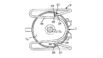
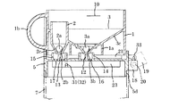
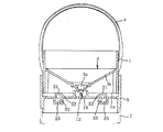
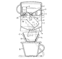
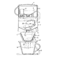
本発明の具体的な実施の形態を図面に基づいて説明すると、図1〜図4において、ドリッパーへの注湯装置は、下端に球体の弁2a、3aによって開閉自在な排湯口2b、3bをそれぞれ備えた蒸らし用貯湯室2と抽出用貯湯室3とを設けている計量容器1と、この計量容器1の上端開口部を開閉する蓋体4を備えた支持台5と、この蓋体4の開閉に連動させて上記計量容器1における蒸らし用貯湯室2と抽出用貯湯室3との排湯口2b、3bを同時に開閉させる弁開閉機構6と、計量容器1の下方に上記支持台5を介して直列状に接続され、その底部7aに上記計量容器1における蒸らし用貯湯室2の排湯口2bから流下する湯を下方に配したドリッパーAに直接注ぐ注湯孔7bを設けている注湯容器7と、この注湯容器7内に配設され、上記抽出用貯湯室3の排湯口3bから流下する湯を一旦受け入れておき、上記蒸らし用貯湯室2からのドリッパーAへの注湯における一定の蒸らし時間後にドリッパーA側に注湯する待機容器8と、スタンド9とから構成されている。   A specific embodiment of the present invention will be described with reference to the drawings. In FIGS. 1 to 4, a pouring device for a dripper is provided with hot water outlets 2b and 3b that can be opened and closed by spherical valves 2a and 3a at the lower end. A measuring container 1 provided with a steaming hot water storage chamber 2 and an extraction hot water storage chamber 3, respectively, a support base 5 including a lid body 4 for opening and closing the upper end opening of the measuring container 1, and the lid body 4. The valve opening / closing mechanism 6 for simultaneously opening and closing the hot water outlets 2b, 3b of the steaming hot water storage chamber 2 and the extraction hot water storage chamber 3 in the measuring container 1 in conjunction with the opening and closing of the measuring container 1, and the support base 5 below the measuring container 1 And a pouring hole 7b for pouring the hot water flowing down from the hot water outlet 2b of the steaming hot water storage chamber 2 in the measuring container 1 directly into the dripper A arranged downward in the bottom portion 7a. Discharged hot water in the extraction hot water storage chamber 3 disposed in the container 7 and the pouring container 7 The hot water flowing down from 3b is once received, and is composed of a stand-by container 8 and a stand 9 for pouring hot water into the dripper A side after a certain steaming time in pouring from the hot water storage chamber 2 to the dripper A. Yes.

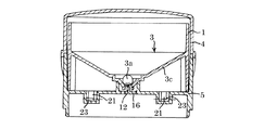
上記計量容器1は長さが短い有底円筒体からなり、その下半部内に、外周縁を全周に亘ってこの計量容器1の内周面に一体に接続させている浅底円錐形状の底部3c(この底部3cは計量容器1の底部を兼備している)を有する上記抽出用貯湯室3が設けられてあり、この抽出用貯湯室3の上端開口部を全面的に開放させていると共にその底部3cの最も深い中心部に上記弁3aによって開閉自在に閉止された排湯口3bを設けている。   The measuring container 1 is formed of a bottomed cylindrical body having a short length, and has a shallow conical shape in which the outer peripheral edge is integrally connected to the inner peripheral surface of the measuring container 1 over the entire circumference in the lower half portion thereof. The extraction hot water storage chamber 3 having a bottom 3c (the bottom 3c also serves as the bottom of the measuring container 1) is provided, and the upper end opening of the extraction hot water storage chamber 3 is fully opened. In addition, a hot water outlet 3b that is opened and closed by the valve 3a is provided at the deepest center of the bottom 3c.

さらに、この抽出用貯湯室3の外周部における前部内に、下端部が先細の円錐形状の底部2cに形成された小径円筒形状の上記蒸らし用貯湯室2が配設されている。この蒸らし用貯湯室2の下端部外周面は抽出用貯湯室3の底部3cにおける前部の外周部に一体に連設されていてその底部2cを抽出用貯湯室3の底部3cの前部から下方に突出させてあり、この円錐形状に形成された底部2cの最も深い中心部に上記弁2aによって開閉自在に閉止された排湯口2bを設けている。なお、下方に向かって開口させている抽出用貯湯室3の排湯口3bの開口端と蒸らし用貯湯室2の排湯口2bの開口端とは同一水平面上に位置させている。   Further, the steaming hot water storage chamber 2 having a small-diameter cylindrical shape having a lower end portion formed in a tapered conical bottom portion 2c is disposed in the front portion of the outer peripheral portion of the extraction hot water storage chamber 3. The outer peripheral surface of the lower end portion of the steaming hot water storage chamber 2 is integrally connected to the outer peripheral portion of the front portion of the bottom portion 3c of the extraction hot water storage chamber 3, and the bottom portion 2c is connected to the front portion of the bottom portion 3c of the hot water storage chamber 3 for extraction. A hot water outlet 2b that is protruded downward and is opened and closed by the valve 2a at the deepest central portion of the bottom 2c formed in the conical shape is provided. The open end of the hot water outlet 3b of the extraction hot water storage chamber 3 and the open end of the hot water outlet 2b of the steaming hot water storage chamber 2 are positioned on the same horizontal plane.

上記計量容器1の上端部内周面にはコーヒーカップBへの一回分の注湯量を示す目盛り10が設けられてあり、この目盛り10よりも下方に上記蒸らし用貯湯室2と抽出用貯湯室3との上端開口部を設けていると共に、蒸らし用貯湯室2の上端開口部よりも抽出用貯湯室3の上端開口部を下方に配置させている。従って、計量容器1内に上記目盛り10まで湯を入れた状態においては、蒸らし用貯湯室2内の湯とこの蒸らし用貯湯室2の上端開口部を湯面まで上方に延長させた仮想円筒内の湯とがコーヒー粉末の蒸らし用の湯として使用され、その他の湯がコーヒー成分の抽出用の湯として使用されるように構成している。   A scale 10 indicating the amount of hot water poured into the coffee cup B is provided on the inner peripheral surface of the upper end of the measuring container 1, and the steaming hot water storage chamber 2 and the extraction hot water storage chamber 3 are located below the scale 10. The upper end opening of the extraction hot water storage chamber 3 is disposed below the upper end opening of the steaming hot water storage chamber 2. Therefore, in the state where hot water is put into the scale 10 in the measuring container 1, the hot water in the steaming hot water storage chamber 2 and the upper end opening of the steaming hot water storage chamber 2 are extended upward to the hot water surface. Is used as hot water for steaming coffee powder, and other hot water is used as hot water for extracting coffee components.

上記蒸らし用貯湯室2の円錐形状の底部2c内と抽出用貯湯室3の浅底円錐形状の底部3c内とにそれぞれ球状に形成された上記弁2a、3aが配設されていて、これらの弁2a、3aの自重によって蒸らし用貯湯室2の底部2cと抽出用貯湯室3の底部3cとに貫設している上記排湯口2b、3bの上端開口部を常態においては閉止してあり、弁2a、3aを上方に突き上げることによって上記排湯口2b、3bの上端開口部を開放させるように構成している。また、抽出用貯湯室3の外底面前後部には、下方に向かって下端が計量容器1の下端に達する位置まで突出した脚壁部1a、1aが設けられている。また、計量容器1の外周部における前面には把手1bが一体に設けられている。   The valves 2a and 3a formed in a spherical shape are disposed in the conical bottom 2c of the steaming hot water storage chamber 2 and the shallow conical bottom 3c of the extraction hot water storage chamber 3, respectively. The upper ends of the hot water outlets 2b and 3b penetrating the bottom 2c of the steaming hot water storage chamber 2 and the bottom 3c of the extraction hot water storage chamber 3 are normally closed by the dead weights of the valves 2a and 3a. The upper ends of the hot water outlets 2b and 3b are opened by pushing the valves 2a and 3a upward. Further, leg wall portions 1a and 1a are provided on the front and rear portions of the extraction hot water storage chamber 3 so that the lower end protrudes downward to reach the lower end of the measuring container 1. A handle 1b is integrally provided on the front surface of the outer peripheral portion of the measuring container 1.

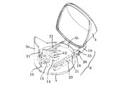
計量容器1の上端開口部を開閉する蓋体4を備えた上記支持台5は、図5〜図8等に示すように、計量容器1の外径よりも僅かに大径の円板形状に形成されてあり、その中心部(中央部)上面に、計量容器1の上記抽出用貯湯室3の排湯口3bの下方に対向させてこの排湯口3bの開口下端側からこの排湯口3bに相対的に挿入して上記弁3aを突き上げ可能なピン12を突設していると共に前部上面に、計量容器1の上記蒸らし用貯湯室2の排湯口2bの下方に対向させてこの排湯口2bの開口下端側からこの排湯口2bに相対的に挿入して上記弁2aを突き上げ可能なピン13を突設している。なお、これらのピン12、13は、それぞれ排湯口2b、3bよりも小径に形成されてあり、その外周面と排湯口2b、3bとの間の隙間を通じて排湯するように構成している。   The support 5 having the lid 4 that opens and closes the upper end opening of the measuring container 1 has a disk shape slightly larger than the outer diameter of the measuring container 1 as shown in FIGS. It is formed, and the upper surface of the central portion (central portion) is opposed to the lower side of the hot water outlet 3b of the extraction hot water storage chamber 3 of the measuring container 1 so as to be relative to the hot water outlet 3b from the lower end side of the hot water outlet 3b. And a pin 12 that can be inserted and pushed up to project the valve 3a, and is disposed on the upper surface of the front portion so as to face the lower side of the hot water outlet 2b of the steaming hot water storage chamber 2 of the measuring container 1. A pin 13 that protrudes from the lower end side of the opening relative to the hot water outlet 2b to push up the valve 2a is provided. These pins 12 and 13 are formed to have a smaller diameter than the hot water outlets 2b and 3b, respectively, and are configured to discharge hot water through a gap between the outer peripheral surface and the hot water outlets 2b and 3b.

また、支持台5の上面中央部と上面前部とに、上記ピン12、13をそれぞれ囲繞した小径筒部14、15を突設してあり、これらの小径筒部14、15によってそれぞれ囲まれた支持台5の中央部と前部とに上下方向に貫通した複数個の湯流下孔16、17が穿設されている。   Further, small-diameter cylindrical portions 14 and 15 surrounding the pins 12 and 13 are respectively provided at the center of the upper surface of the support base 5 and the front surface of the upper surface, and are surrounded by the small-diameter cylindrical portions 14 and 15, respectively. A plurality of hot water flow holes 16, 17 penetrating in the vertical direction are formed in the center portion and the front portion of the support base 5.

さらに、支持台5の後部側における外周面両側部に軸受用突片18、18を突設してあり、これらの突片18、18に計量容器1の上端開口部を開閉する上記蓋体4の後面両側部に突設したアーム片19、19の下端部を軸体20によって回動自在に枢着して蓋体4により計量容器1の開口端を開閉させるように構成していると共に、支持台5の上面両側部には前後方向に長い一定幅を有する直状の凹溝23、23(図9〜図12参照)が左右に一定間隔を存して互いに平行に設けられていて、これらの凹溝23、23内に計量容器1を架設状態に載置させる互いに平行な左右一対の水平リフトバー21、21が配設されている。   Further, bearing protrusions 18, 18 are provided on both sides of the outer peripheral surface on the rear side of the support base 5, and the lid 4 that opens and closes the upper end opening of the measuring container 1 on these protrusions 18, 18. The lower ends of the arm pieces 19, 19 projecting on both sides of the rear surface are pivotally mounted by the shaft body 20 so that the opening end of the measuring container 1 is opened and closed by the lid body 4. On both sides of the upper surface of the support base 5, straight concave grooves 23 and 23 (see FIGS. 9 to 12) having a constant width long in the front-rear direction are provided in parallel to each other with a constant interval on the left and right. A pair of left and right horizontal lift bars 21, 21 parallel to each other for placing the measuring container 1 in an erected state are disposed in the concave grooves 23, 23.

これらの水平リフトバー21、21の前端部は、基端部を凹溝23、23の前端部の両側内壁に支持された支軸32に枢着しているリンク片22、22の先端部に回動自在に枢着されている共に、後端部は、支持台5の後端から後方に向かった開口している凹溝23、23の後端から後方に突出していて、この後端部を上記蓋体4のアーム片19、19における上記軸体20の枢着部から上記リンク片22の長さに略等しい距離を存した中間部に突設している支軸33に回動自在に枢着してあり、蓋体4の開閉操作に連動してこれらの水平リフトバー21、21を同時に上下動させ、互いに平行に保持したまま上記凹溝23、23から出没自在となるように構成している。   The front ends of these horizontal lift bars 21 and 21 are rotated around the distal ends of the link pieces 22 and 22 pivotally attached to the support shafts 32 supported on the inner walls on both sides of the front ends of the concave grooves 23 and 23, respectively. While being pivotally mounted, the rear end portion protrudes rearward from the rear end of the recessed grooves 23, 23 opening rearward from the rear end of the support base 5, and this rear end portion is The arm piece 19, 19 of the lid body 4 is rotatable about a support shaft 33 projecting from a pivoting portion of the shaft body 20 to an intermediate portion having a distance substantially equal to the length of the link piece 22. The horizontal lift bars 21 and 21 are simultaneously moved up and down in conjunction with the opening / closing operation of the lid body 4 so that they can be moved in and out of the concave grooves 23 and 23 while being held parallel to each other. ing.

そして、上記計量容器1と注湯容器7との間に配設された上記支持台5と、この支持台5に枢着されて計量容器1の開口端を開閉する蓋体4と、蓋体4の開閉に連動して上下動する上記水平リフトバー21、21とによって、水平リフトバー21、21上に載置した計量容器1の下動時に上記支持台5に突設しているピン12、13で排湯口2b、3bの弁2a、3aを押し上げて開弁させ、計量容器の上動時に上記支持台5に突設しているピン12、13から排湯口2b、3bを上方に離間させて閉弁させる弁開閉機構6(図5参照)を構成している。   And the said support stand 5 arrange | positioned between the said measurement container 1 and the pouring container 7, the cover body 4 which is pivotally attached to this support stand 5, and opens and closes the opening end of the measurement container 1, and a cover body The pins 12, 13 projecting from the support 5 when the measuring container 1 placed on the horizontal lift bars 21, 21 is moved downward by the horizontal lift bars 21, 21 moving up and down in conjunction with opening and closing of 4. The valve 2a, 3a of the hot water outlets 2b, 3b is pushed up to open the valve, and the hot water outlets 2b, 3b are separated upward from the pins 12, 13 protruding from the support base 5 when the measuring container is moved upward. A valve opening / closing mechanism 6 (see FIG. 5) for closing the valve is configured.

上記支持台5の前半部周縁には周壁5aが突設されていると共に後半部周縁にはこの周壁5aよりも高さが低い周壁5bが突設されていて、これらの周壁5a、5bで囲まれた空間部内に上記計量容器1を挿脱自在に配設するようにして構成していると共に、上記前半部側の周壁5aの前面中央部に計量容器1の把手1bのガイドとなる縦長孔24が上端から下端近傍部に達するまで設けられてあり、この縦長孔24内に上方から把手1bを挿入して計量容器1を前側周壁5a、5bによって囲まれた支持台5上に収納し、その外底面を上記水平リフトバー21、21間上に架設状態となるように載置させるように構成している。さらに、支持台5の外周縁には下方に向かって一定長さの下側周壁部5cが設けられてあり、この下側周壁部の下部に断面L字状の周段部5dを全周に亘って形成している。   A peripheral wall 5a protrudes from the peripheral edge of the front half of the support base 5 and a peripheral wall 5b lower than the peripheral wall 5a protrudes from the peripheral edge of the rear half, and is surrounded by the peripheral walls 5a and 5b. The measuring container 1 is configured to be removably disposed in the space, and a vertically long hole serving as a guide for the handle 1b of the measuring container 1 is formed in the center of the front surface of the peripheral wall 5a on the front half side. 24 is provided from the upper end to the vicinity of the lower end, and the handle 1b is inserted into the vertically long hole 24 from above to accommodate the measuring container 1 on the support base 5 surrounded by the front peripheral walls 5a and 5b. The outer bottom surface is configured to be placed between the horizontal lift bars 21 and 21 so as to be installed. Further, a lower peripheral wall portion 5c having a predetermined length is provided on the outer peripheral edge of the support base 5 downward, and a circumferential step portion 5d having an L-shaped cross section is provided around the entire periphery of the lower peripheral wall portion. It is formed over.

上記注湯容器7内に配設されて、上記抽出用貯湯室3の排湯口3bから流下する湯を一旦受け入れておき、上記蒸らし用貯湯室2からのドリッパーAへの注湯における一定の蒸らし時間後にドリッパーA側に注湯する待機容器8はししおどし(鹿威し)の構造に構成されている。   The hot water which is disposed in the pouring vessel 7 and flows down from the hot water outlet 3b of the extraction hot water storage chamber 3 is once received, and a constant steaming in pouring from the hot water storage chamber 2 to the dripper A is performed. The standby container 8 for pouring water into the dripper A side after time is configured to have a shishidoshi (deering) structure.

具体的には、注湯容器7の底部7aの上面両側部における後側寄り部分に一定高さを有する軸受片25、25が突設されている一方、待機容器8は有底角筒形状に形成され且つ上端開口部が斜めにカットされて抽出用貯湯室3の排湯口3bからの湯受入れ口8aに形成されていると共にこの待機容器8の長さ方向の中間部両側面に軸26、26が突設されてあり、この軸26、26を上記軸受片25、25に回動自在に支承させ、湯を受け入れていない空の状態においては重心を軸26よりも後方側に位置させて上端から下端に向かって斜め後方に傾斜させた状態にして注湯容器7の底部7aに突設した受止突片7cにその底部を受止させている。   Specifically, bearing pieces 25 and 25 having a fixed height project from the rear side portions on both sides of the upper surface of the bottom portion 7a of the pouring vessel 7, while the standby vessel 8 has a bottomed rectangular tube shape. The upper end opening is cut obliquely to form a hot water receiving port 8a from the hot water outlet 3b of the extraction hot water storage chamber 3, and shafts 26 are provided on both side surfaces of the intermediate portion in the lengthwise direction of the standby container 8. 26 is provided so that the shafts 26 and 26 are rotatably supported by the bearing pieces 25 and 25, and the center of gravity is positioned behind the shaft 26 in an empty state where hot water is not received. The bottom portion is received by a receiving protrusion piece 7c that protrudes from the bottom portion 7a of the pouring vessel 7 in a state inclined obliquely rearward from the upper end toward the lower end.

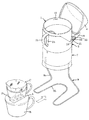
注湯容器7は支持台5とその外周面が同径の円筒形状に形成されていると共に、その底部7aを注湯容器7の下端部内周面に一体に連設している外周縁から中心部(中央部)に向かって緩やかに下方に傾斜させた浅底円錐形状に形成してあり、この底部7aの中心部に上記注湯孔7bを設けている。さらに、注湯容器7の上端部は上記支持台5の下側周壁部5cに形成している周段部5dに嵌脱自在に嵌合させて支持台5の下方に注湯容器7を直列に接続させた係合部7dに形成されている。   The pouring vessel 7 has a support base 5 and its outer peripheral surface formed in a cylindrical shape having the same diameter, and its bottom portion 7a is centered from the outer peripheral edge integrally connected to the inner peripheral surface of the lower end portion of the pouring vessel 7. It is formed in a shallow conical shape that is gently inclined downward toward the center (center), and the pouring hole 7b is provided at the center of the bottom 7a. Further, the upper end portion of the pouring vessel 7 is detachably fitted to the peripheral step portion 5d formed on the lower peripheral wall portion 5c of the support base 5 so that the pouring vessel 7 is connected in series below the support base 5. It is formed in the engaging part 7d connected to.

また、この注湯容器7の底部7aの外底面における両側部には、注湯容器7の下方にコーヒーカップBとドリッパーAを設置可能な空間部を設けるためのスタンド9を接続する取付孔27、27を有する左右一対の筒体部28、28が下方に向かって突設されている。さらに、この筒体部28、28よりも高さ(長さ)の異なる取付孔29、29を有する左右一対の筒体部30、30(図2参照)も突設されていて、スタンド9の設置面からの注湯容器7の配置高さを変更可能に構成している。   In addition, mounting holes 27 for connecting a stand 9 for providing a space where the coffee cup B and the dripper A can be installed below the pouring vessel 7 are provided on both sides of the bottom 7a of the pouring vessel 7 at the bottom. , 27 and a pair of left and right cylindrical body portions 28, 28 project downward. Further, a pair of left and right cylindrical body portions 30 and 30 (see FIG. 2) having mounting holes 29 and 29 having different heights (lengths) than the cylindrical body portions 28 and 28 are also provided so as to protrude from the stand 9. The arrangement height of the pouring container 7 from the installation surface can be changed.

スタンド9は、上端部を上記注湯容器7の底部7aに設けている左右一対の筒体部28、28(30、30)の取付孔27、27(29、29)に差し込むことによって注湯容器7の外底面に接続させるための左右一対の支柱部9a、9aと、これらの支柱部9a、9aの下端から水平方向に屈曲し、互いに平面U字状に連なった設置用座部9bとから形成されている。   The stand 9 is poured by inserting the upper end portion into the mounting holes 27, 27 (29, 29) of the pair of left and right cylindrical body portions 28, 28 (30, 30) provided in the bottom portion 7a of the pouring vessel 7. A pair of left and right support columns 9a, 9a to be connected to the outer bottom surface of the container 7, and an installation seat 9b bent horizontally from the lower ends of these support columns 9a, 9a and connected to each other in a plane U shape; Formed from.

上記のように構成したドリッパーへの注湯装置は、不使用時には図4に示すように、計量容器1やこの計量容器1の蓋体4を設けている支持台5、注湯容器7、スタンド9等は別々にして保管するようにしてあり、使用時にはスタンド9の支柱部9a、9aの上端部を注湯容器7の外底面に突設している左右一対の筒体部28、28(30、30)の取付孔27、27(29、29)に差し込むことによってスタンド9上に注湯容器7を取付けると共に、支持台5の下側周壁部5cの下端部に設けている段周部5dを上記注湯容器7の上端係合部7dに嵌合させることによって注湯容器7上に支持台5を直列状に接続する。なお、注湯容器7内には予め待機容器8が取付けられていると共に支持台5には水平リフトバー21、21及び蓋体4が取付けられている。   As shown in FIG. 4, the pouring device for the dripper constructed as described above has a measuring base 1, a support base 5 provided with a lid 4 of the measuring container 1, a pouring container 7, and a stand as shown in FIG. 4. 9 and the like are stored separately, and when used, a pair of left and right cylindrical body portions 28, 28 (the upper end portions of the support column portions 9a, 9a of the stand 9 project from the outer bottom surface of the pouring vessel 7 ( 30 and 30) are inserted into the mounting holes 27 and 27 (29 and 29) to attach the pouring container 7 on the stand 9, and the stepped peripheral portion provided at the lower end of the lower peripheral wall portion 5c of the support base 5 The support 5 is connected in series on the pouring vessel 7 by fitting 5d to the upper end engaging portion 7d of the pouring vessel 7. A standby container 8 is attached in advance to the pouring container 7 and horizontal lift bars 21 and 21 and a lid 4 are attached to the support base 5.

さらに、蓋体4を後方に傾倒させて支持台5の上端開口部を全面的に開放させた状態にして、この支持台5の周壁5a、5bによって囲まれた空間部内に上方から計量容器1を挿入する。この挿入操作は、計量容器1の把手1bを把持しながら該把手1bを支持台5の前側周壁5aに前面に設けている縦長孔24に上方から挿入しながら行う。従って、計量容器1はその蒸らし用貯湯室2側を前方側に向けた状態にして正確に支持台5上に設置することができる。この計量容器1の挿入時には蓋体4が開放されていてその開放により支持台5の底部両側に設けている水平リフトバー21、21がリンク片22、22の起立によって支持台5の凹溝23、23から上方に突出してあり、計量容器1の脚部1aをこの水平リフトバー21、21上に載置させることによって計量容器1を支持台5上に設置する。   Further, the lid body 4 is tilted rearward so that the upper end opening of the support base 5 is fully opened, and the measuring container 1 is viewed from above in the space surrounded by the peripheral walls 5a and 5b of the support base 5. Insert. This insertion operation is performed while holding the handle 1b of the measuring container 1 and inserting the handle 1b into the longitudinally long hole 24 provided on the front surface of the front peripheral wall 5a of the support base 5 from above. Accordingly, the measuring container 1 can be accurately placed on the support 5 with the steaming hot water storage chamber 2 side facing forward. When the weighing container 1 is inserted, the lid 4 is opened, and the horizontal lift bars 21, 21 provided on both sides of the bottom of the support base 5 by the opening of the weighing container 1 are recessed grooves 23 of the support base 5, The measuring container 1 is placed on the support base 5 by projecting upward from 23 and placing the leg 1 a of the measuring container 1 on the horizontal lift bars 21, 21.

このように、ドリッパーへの注湯装置を組立てたのち、スタンド9によって支持されている注湯容器7の下方に、開口部にドリッパーAを配設したコーヒーカップBを設置する(図13参照)。なお、ドリッパーAとしては、漏斗状に形成されたドリッパー本体a1の底部に抽出孔a2を設けていると共に、底部外周にコーヒーカップBの開口端に載置する円板形状のフランジ部a3を設けてなり、ドリッパー本体a1の内面に沿って濾紙Cを展開、敷設し、この濾紙C内に一回分のコーヒー粉末Dを投入するように構成しているが、このようなドリッパーAに限らず、例えば、図19に示すように、一回分のコーヒー粉末Dを収容した濾紙からなるコーヒーバッグA'の開口端部に、コーヒーカップBの開口縁に架設状態に支持させる支持片Eを設けてなる構造のドリッパーBであってもよい。   In this way, after assembling the pouring device for the dripper, the coffee cup B in which the dripper A is disposed in the opening is installed below the pouring vessel 7 supported by the stand 9 (see FIG. 13). . As the dripper A, an extraction hole a2 is provided at the bottom of a dripper body a1 formed in a funnel shape, and a disc-shaped flange portion a3 that is placed on the open end of the coffee cup B is provided at the outer periphery of the bottom. The filter paper C is developed and laid along the inner surface of the dripper body a1, and the coffee powder D is fed into the filter paper C once. However, the present invention is not limited to such a dripper A, For example, as shown in FIG. 19, a support piece E is provided at the opening end of a coffee bag A ′ made of filter paper containing a single dose of coffee powder D and supported on the opening edge of the coffee cup B in a erected state. A dripper B having a structure may be used.

開口端にドリッパーAを設けたコーヒーカップBを注湯容器7の下方に設置したのち、蓋体4が開放状態の計量容器1内にポット等から湯(熱湯)を目盛り10に達するまで注ぎ入れる(図14、図15参照)。この際、蓋体4の開放によって計量容器1を支持している水平リフトバー21、21が支持台5の底面から上方に上昇していて、計量容器1が持ち上げられている。従って、計量容器1内に設けている蒸らし用貯湯室2と抽出用貯湯室3との排湯口2b、3bが支持台5の中央部上面と前部上面とに突設しているピン12、13からそれぞれ上方に離間してあり、これらの排湯口2b、3bが球体弁からなる弁2a、3aの自重によって閉止されていて、下方に漏れることなく計量容器1内に収容された状態を保持している。   After the coffee cup B provided with the dripper A at the open end is installed below the pouring container 7, hot water (hot water) is poured into the measuring container 1 with the lid 4 open from the pot or the like until the scale 10 is reached. (See Figure 14 and Figure 15). At this time, the horizontal lift bars 21, 21 supporting the weighing container 1 are lifted upward from the bottom surface of the support 5 by opening the lid 4, and the weighing container 1 is lifted. Accordingly, the hot water outlets 2b and 3b of the steaming hot water storage chamber 2 and the extraction hot water storage chamber 3 provided in the measuring container 1 protrude from the center upper surface and the front upper surface of the support base 5, respectively. 13 are spaced apart upward from each other, and the drains 2b and 3b are closed by the dead weight of the valves 2a and 3a made of spherical valves, and kept in the measuring container 1 without leaking downward. doing.

計量容器1内にその目盛り10に達するまで注湯したのち蓋体4を閉止すると、図11、図12、図16に示すようにその閉止操作に連動して水平リフトバー21、21が降下し、これらの水平リフトバー21、21を配設している支持台5の両側凹溝23、23内に没入する。この水平リフトバー21、21の降下によって水平リフトバー21、21上に載置している計量容器1も一体に降下し、この計量容器1内に設けている蒸らし用貯湯室2と抽出用貯湯室3との排湯口2b、3b内に支持台5の中央部上面と前部上面とに突設しているピン12、13が相対的に挿入してこれらのピン12、13の先端で弁2a、3aを突き上げ、排湯口2b、3bを開放させる。   When the lid 4 is closed after pouring in the measuring container 1 until the scale 10 is reached, the horizontal lift bars 21, 21 are lowered in conjunction with the closing operation, as shown in FIGS. The horizontal lift bars 21 and 21 are immersed in the recessed grooves 23 and 23 on both sides of the support 5 on which the horizontal lift bars 21 and 21 are disposed. As the horizontal lift bars 21 and 21 are lowered, the measuring container 1 placed on the horizontal lift bars 21 and 21 is also lowered integrally, and the steaming hot water storage chamber 2 and the extraction hot water storage chamber 3 provided in the measuring container 1. Pins 12 and 13 projecting from the center upper surface and the front upper surface of the support base 5 are relatively inserted into the hot water outlets 2b and 3b, and the valves 2a and 13b are inserted at the tips of these pins 12 and 13, respectively. 3a is pushed up and the hot water outlets 2b and 3b are opened.

そうすると、蒸らし用貯湯室2内と抽出用貯湯室3内の湯が排湯口2b、3bから支持台5におけるピン12、13の周囲に穿設された湯流下孔16、17を通じて注湯容器7内に流出する。この際、蒸らし用貯湯室2内から排湯口2b、湯流下孔16を通じて流出する湯は、直接、注湯容器7の底部7a上に流下する一方、抽出用貯湯室3内から排湯口3b、湯流下孔17を通じて流出する湯は、注湯容器7の底部7a上に流下することなく注湯容器7内に配設している待機容器8内に一旦貯留される。   Then, the hot water in the steaming hot water storage chamber 2 and the extraction hot water storage chamber 3 passes from the hot water outlets 2b and 3b through the hot water flow holes 16 and 17 drilled around the pins 12 and 13 in the support base 5. Flows out. At this time, the hot water flowing out from the steaming hot water storage chamber 2 through the hot water outlet 2b and the hot water lower hole 16 flows down directly onto the bottom 7a of the pouring vessel 7, while the hot water outlet 3b from the hot water storage chamber 3 for extraction, The hot water flowing out through the hot water flow hole 17 is temporarily stored in the standby container 8 disposed in the hot water container 7 without flowing down on the bottom 7 a of the hot water container 7.

計量容器1内に収容している湯が排湯口2b、3bを通じて注湯容器7側に排出されるに従って、計量容器1内の湯面が降下し、抽出用貯湯室3の上端開口部よりもその上端開口部が上方に位置している蒸らし用貯湯室2の開口端まで降下すると、蒸らし用貯湯室2側へは湯が入ることなくこの蒸らし用貯湯室2内の湯が引き続いて注湯容器7の底部7a上に流下してこの底部7aの傾斜上面を伝って底部7aの中心部に設けている注湯孔7bからドリッパーA内に注ぎ込み、ドリッパーAの濾紙C内のコーヒー粉末D全体をこの湯によって一定時間蒸らしてコーヒー粉末Dを膨潤させ、コーヒー成分を抽出し易くする。   As the hot water stored in the measuring container 1 is discharged to the pouring container 7 through the hot water outlets 2b and 3b, the hot water level in the measuring container 1 is lowered and is more than the upper end opening of the hot water storage chamber 3 for extraction. When the upper end opening is lowered to the opening end of the steaming hot water storage chamber 2, the hot water in the steaming hot water storage chamber 2 continues to be poured without entering the steaming hot water storage chamber 2 side. The coffee powder D in the filter paper C of the dripper A is poured into the dripper A through the pouring hole 7b provided in the center of the bottom portion 7a after flowing down on the bottom portion 7a of the container 7 and along the inclined upper surface of the bottom portion 7a. Is steamed with this hot water for a certain period of time to swell the coffee powder D, thereby facilitating extraction of coffee components.

このように、蒸らし用貯湯室2から流出する湯によってコーヒー粉末Dを膨潤させている間に、抽出用貯湯室3から流出する湯を一旦、待機容器8内に受け入れさせ、コーヒー粉末Dの蒸らし時間が完了する際に、待機容器8内に充満した湯によって図17に示すように、この待機容器8の上端開口部が下方に傾動して待機容器8内の湯が注湯容器7の底部7a上に流下し、この底部7aの中心部に設けている上記注湯孔7bからドリッパーA内に注ぎ込んで上記蒸らしによって膨潤したコーヒー粉末Dの成分を抽出し、抽出したコーヒー液を濾紙C、抽出孔a2を通じてコーヒーカップBに収容する。なお、待機容器8はその内部の湯が所定量に達して待機容器8の重心の位置が待機容器8の回動中心である軸26よりも前方に移動し、軸26を支点として前方に向かって斜め下方に傾動して内部の湯を排出し、排出後に元の状態に復帰する。   Thus, while the coffee powder D is swollen by the hot water flowing out from the steaming hot water storage chamber 2, the hot water flowing out from the extraction hot water storage chamber 3 is once received in the standby container 8 to steam the coffee powder D. When the time is completed, as shown in FIG. 17 by the hot water filled in the standby container 8, the upper end opening of the standby container 8 tilts downward so that the hot water in the standby container 8 becomes the bottom of the pouring container 7. The components of the coffee powder D poured into the dripper A through the pouring hole 7b provided in the center of the bottom portion 7a and swollen by the steaming are extracted. The coffee cup B is accommodated through the extraction hole a2. Note that the standby container 8 reaches a predetermined amount of hot water, and the position of the center of gravity of the standby container 8 moves forward from the shaft 26 that is the rotation center of the standby container 8, and moves forward with the shaft 26 as a fulcrum. It tilts diagonally downward to discharge the hot water inside and returns to its original state after the discharge.

蒸らし用貯湯室2側からドリッパーAに注ぎ込まれる上記蒸らし用湯によるコーヒー粉末Dの蒸らし工程は、コーヒー粉末Dを最も良好な状態に膨潤させるに必要な時間だけ行われ、この時間の経過後に上記待機容器8側からドリッパーAに抽出用の湯を注ぎ込むことによってまろやかで香りのよい美味しいコーヒーを抽出することができる。   The steaming step of the coffee powder D by the steaming hot water poured into the dripper A from the steaming hot water storage chamber 2 side is performed only for the time necessary to swell the coffee powder D to the best condition, and after this time has elapsed, By pouring hot water for extraction into the dripper A from the standby container 8 side, it is possible to extract mellow and fragrant delicious coffee.

例えば、計量容器1に注ぐ湯量が略160cc、蒸らし用貯湯室2の排湯口2bからドリッパーA側に注ぐ湯量を略20cc、抽出用貯湯室3の排湯口3bからドリッパーA側に注ぐ湯量を略140cc、蒸らし用貯湯室2側からのドリッパーA側への注湯後、待機容器8側からのドリッパーA側への注湯行う時間差が略15秒となるように構成しておくと、コーヒー成分の良好な抽出を可能にすることができる。   For example, the amount of hot water poured into the measuring container 1 is about 160 cc, the amount of hot water poured into the dripper A side from the hot water outlet 2b of the steaming hot water storage chamber 2 is about 20 cc, and the amount of hot water poured into the dripper A side from the hot water outlet 3b of the hot water storage chamber 3 is extracted. 140 cc, after pouring from the steaming hot water storage chamber 2 side to the dripper A side, the time difference of pouring from the standby container 8 side to the dripper A side is approximately 15 seconds, so that the coffee component Good extraction can be made possible.

なお、以上の実施例においては、蒸らし用貯湯室2と抽出用貯湯室3との排湯口2b、3bを開閉する弁2a、3aとして球体弁を使用しているが、下側からピン12、13により開放可能な平たい弁であってもよく、その他の開閉手段を採用してもよい。   In the above embodiment, a spherical valve is used as the valves 2a and 3a for opening and closing the hot water outlets 2b and 3b of the steaming hot water storage chamber 2 and the extraction hot water storage chamber 3, but the pin 12 from the lower side, It may be a flat valve that can be opened by 13, or other opening / closing means may be employed.

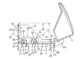
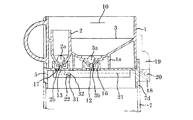
さらに、蒸らし用貯湯室2からドリッパーA側への注湯の開始と同時に抽出用貯湯室3からの注湯をドリッパーA側に行うことなく一旦、待機容器8内に収容しておき、蒸らし用貯湯室2からの注湯によってコーヒー粉末Dが良好に蒸らされた後に、引き続いて待機容器8からドリッパーA側に注湯を行うようにするための待機容器8の作動は、上記のように、「ししおどし」の構造に行っているが、このような手段に限定されることなく、例えば、図20〜図22に示すように、サイフォンの原理を利用した構造を採用してもよい。   Further, simultaneously with the start of pouring from the steaming hot water storage chamber 2 to the dripper A side, the pouring of the hot water from the extraction hot water storage chamber 3 is temporarily stored in the standby container 8 without performing the pouring to the dripper A side. After the coffee powder D is successfully steamed by the pouring from the hot water storage chamber 2, the operation of the standby container 8 for continuously pouring the hot water from the standby container 8 to the dripper A side is as described above. However, the present invention is not limited to such a structure, and for example, as shown in FIGS. 20 to 22, a structure using the principle of siphon may be adopted.

このサイフォンの原理を利用した構造を備えた待機容器8'は、一定深さを有する四角形の箱状に形成されていて、注湯容器7の底部7aの上面両側部における後側寄り部分に突設した一定高さを有する軸受片25’、25’に両外側面の中央部に突設している軸部26' 、26' を回動不能に且つ取り外し可能に支持させてあり、この待機容器8'内に、逆U字形のサイフォン管40が、その下向きに開口した一方の開口端40a を待機容器8'の内底面に近接させた状態で臨ませ、他方の下向きに開口した開口端40b を待機容器8'の底部を水密状態に貫通して注湯容器7の内底面に臨ませた状態にして配設、固定している。なお、上記サイフォン管40の上端屈曲部は、待機容器8'の上端開口部よりも下方に位置している。   The standby container 8 ′ having a structure utilizing the principle of the siphon is formed in a rectangular box shape having a certain depth, and protrudes toward a rear side portion on both sides of the upper surface of the bottom 7a of the pouring container 7. The shafts 26 'and 26' projecting from the center portions of the outer side surfaces of the bearing pieces 25 'and 25' having a fixed height are supported so as not to rotate and to be removable. An inverted U-shaped siphon tube 40 faces into the container 8 'with one open end 40a opened downward facing the inner bottom surface of the standby container 8', and the other open end opened downward 40b is disposed and fixed in such a manner that the bottom of the standby container 8 ′ penetrates into the watertight state and faces the inner bottom surface of the pouring container 7. Note that the upper end bent portion of the siphon tube 40 is located below the upper end opening of the standby container 8 ′.

サイフォン管40を備えた待機容器8'以外の計量容器1や蒸らし用貯湯室2、抽出用貯湯室3、抽出用貯湯室3、蓋体4、支持台5、弁開閉機構6、注湯容器7等の注湯装置を構成している構造は上記実施例と同様であるので、同一部分には同一符号を付して詳細な説明を省略する。   Measuring container 1 other than standby container 8 ′ equipped with siphon tube 40, steaming hot water storage chamber 2, extraction hot water storage chamber 3, extraction hot water storage chamber 3, lid 4, support base 5, valve opening / closing mechanism 6, pouring container Since the structure constituting the pouring device such as 7 is the same as that of the above embodiment, the same parts are denoted by the same reference numerals and detailed description thereof is omitted.

このように構成したので、計量容器1内にその目盛り10に達するまで注湯したのち蓋体4を閉止し、上記実施例と同様に、この閉止によって連動する水平リフトバー21、21の降下によって水平リフトバー21、21上に載置している計量容器1内の蒸らし用貯湯室2と抽出用貯湯室3との排湯口2b、3bを支持台5に突設しているピン12、13によって突き上げ、排湯口2b、3bを開放させる。   Since it is configured in this manner, the lid 4 is closed after pouring in the measuring container 1 until the graduation 10 is reached, and in the same manner as in the above embodiment, the horizontal lift bars 21, 21 that are interlocked by this closing are moved horizontally. The hot water outlets 2b and 3b of the steaming hot water storage chamber 2 and the extraction hot water storage chamber 3 in the measuring container 1 placed on the lift bars 21 and 21 are pushed up by pins 12 and 13 protruding from the support base 5. Then, the hot water outlets 2b and 3b are opened.

そうすると、蒸らし用貯湯室2内と抽出用貯湯室3内の湯が排湯口2b、3bから支持台5におけるピン12、13の周囲に穿設された湯流下孔16、17を通じて注湯容器7内に流出する。この際、蒸らし用貯湯室2内から排湯口2b、湯流下孔16を通じて流出する湯は、直接、注湯容器7の底部7a上に流下する一方、抽出用貯湯室3内から排湯口3b、湯流下孔17を通じて流出する湯は、注湯容器7の底部7a上に流下することなく注湯容器7内に配設している待機容器8'内に収容される。   Then, the hot water in the steaming hot water storage chamber 2 and the extraction hot water storage chamber 3 passes from the hot water outlets 2b and 3b through the hot water flow holes 16 and 17 drilled around the pins 12 and 13 in the support base 5. Flows out. At this time, the hot water flowing out from the steaming hot water storage chamber 2 through the hot water outlet 2b and the hot water lower hole 16 flows down directly onto the bottom 7a of the pouring vessel 7, while the hot water outlet 3b from the hot water storage chamber 3 for extraction, The hot water flowing out through the hot water flow hole 17 is accommodated in the standby container 8 ′ disposed in the hot water container 7 without flowing down onto the bottom 7 a of the hot water container 7.

蒸らし用貯湯室2内から排湯口2b、湯流下孔16を通じて注湯容器7の底部7a上に流下した湯は、この底部7aの傾斜上面を伝って底部7aの中心部に設けている注湯孔7bからドリッパーA内に注ぎ込まれて、ドリッパーAの濾紙C内のコーヒー粉末D全体をこの湯によって蒸らしてコーヒー粉末Dを膨潤させ、コーヒー成分を抽出し易くする。   The hot water flowing from the steaming hot water storage chamber 2 through the hot water outlet 2b and the hot water lower hole 16 onto the bottom portion 7a of the pouring vessel 7 flows along the inclined upper surface of the bottom portion 7a and is poured into the central portion of the bottom portion 7a. It is poured into the dripper A through the holes 7b, and the entire coffee powder D in the filter paper C of the dripper A is steamed with this hot water to swell the coffee powder D, thereby facilitating extraction of coffee components.

このように、蒸らし用貯湯室2から流出する湯によってコーヒー粉末Dを一定時間、膨潤させている間に、抽出用貯湯室3から流出する湯が待機容器8'内に充満し、コーヒー粉末Dの蒸らし時間が完了する際に、待機容器8'の内底面に臨ませている一方の開口端40a
からサイフォン管40内に浸入した湯がサイフォン管40の上端屈曲部の高さまで達して待機容器8'の湯面に作用する大気圧により、待機容器8'内の湯がサイフォン管40内を通じてこのサイフォン管40の他方の開口端40b から注湯容器7の底部7a上に流下し、この底部7aの中心部に設けている上記注湯孔7bからドリッパーA内に注ぎ込んで上記蒸らしによって膨潤したコーヒー粉末Dの成分を抽出し、抽出したコーヒー液を濾紙C、抽出孔a2を通じてコーヒーカップBに収容する。
Thus, while the coffee powder D is swollen for a certain period of time with the hot water flowing out of the steaming hot water storage chamber 2, the hot water flowing out of the extraction hot water storage chamber 3 is filled in the standby container 8 ', and the coffee powder D When the steaming time is completed, one open end 40a facing the inner bottom surface of the standby container 8 ′
The hot water in the siphon tube 40 reaches the height of the upper bent portion of the siphon tube 40 and acts on the hot water surface of the standby vessel 8 ', so that the hot water in the standby vessel 8' passes through the siphon tube 40. The coffee flows down from the other open end 40b of the siphon tube 40 onto the bottom 7a of the pouring vessel 7, poured into the dripper A from the pouring hole 7b provided at the center of the bottom 7a, and swollen by the steaming. The components of the powder D are extracted, and the extracted coffee liquid is stored in the coffee cup B through the filter paper C and the extraction hole a2.

蒸らし用貯湯室2側からドリッパーAに注ぎ込まれる上記蒸らし用湯によるコーヒー粉末Dの蒸らし工程は、上記実施例と同様に、コーヒー粉末Dを最も良好な状態に膨潤させるに必要な時間だけ行われ、この時間の経過後に上記待機容器8'側からドリッパーAに抽出用の湯を注ぎ込むことによってまろやかで香りのよい美味しいコーヒーを抽出することができる。   The steaming step of the coffee powder D by the steaming hot water poured into the dripper A from the steaming hot water storage chamber 2 side is performed for the time necessary to swell the coffee powder D to the best state, as in the above embodiment. After the elapse of this time, by pouring hot water for extraction into the dripper A from the waiting container 8 'side, a mellow and fragrant delicious coffee can be extracted.

1 計量容器
2 蒸らし用貯湯室
3 抽出用貯湯室
2a、3a 弁
2b、3b 排湯口
4 蓋体
5 支持台
6 弁開閉機構
7 注湯容器
8 待機容器
9 スタンド
10 目盛り
12、13 ピン
16、17 湯流下孔
21 水平リフトバー
24 縦長孔
A ドリッパー
B コーヒーカップ
1 Measuring container 2 Hot water storage room for steaming 3 Hot water storage room for extraction
2a, 3a valve
2b, 3b Hot water outlet 4 Lid 5 Support base 6 Valve open / close mechanism 7 Pouring container 8 Standby container 9 Stand
10 scales
12, 13 pins
16, 17
21 Horizontal lift bar
24 Long hole A Dripper B Coffee cup

Claims (8)

下端に弁によって開閉自在な排湯口をそれぞれ設けている蒸らし用貯湯室と抽出用湯室とを有する計量容器と、この計量容器における上記蒸らし用貯湯室と抽出用貯湯室との排湯口に設けている弁を同時に開閉させる弁開閉機構と、計量容器の下方に直列状に接続され、底部に上記蒸らし用注湯室の排湯口から流下する湯を直接ドリッパーに注ぐ注湯孔を設けている注湯容器と、この注湯容器内に配設され、上記抽出用貯湯室の排湯口から流下する湯を一旦受け入れておき、上記蒸らし用貯湯室からのドリッパへの注湯における一定の蒸らし時間後に注湯容器の上記注湯孔を設けている底部上に排出するように構成した待機容器とからなることを特徴とするドリッパへの注湯装置。   A measuring container having a steaming hot water storage chamber and an extraction hot water chamber each provided with a hot water outlet that can be opened and closed by a valve at the lower end, and provided in the hot water outlets of the steaming hot water storage chamber and the extraction hot water storage chamber in the measuring container A valve opening / closing mechanism that opens and closes the valves simultaneously, and a pouring hole that is connected in series below the measuring container and that pours hot water flowing down from the hot water outlet of the steaming pouring chamber directly into the dripper The hot water container and the hot water flowing in from the hot water outlet of the extraction hot water storage chamber are temporarily received and fixed steaming time in the hot water pouring from the hot water storage chamber to the dripper An apparatus for pouring water into a dripper, comprising: a standby container configured to be discharged onto a bottom portion provided with the above-mentioned pouring hole of the pouring container later. 計量容器に一回分の注湯量を示す目盛りが設けられてあり、この目盛りよりも下方に蒸らし用貯湯室と抽出用貯湯室との上端開口部を設けていることを特徴とする請求項1に記載のドリッパーへの注湯装置。   The scale which shows the amount of pouring for one time is provided in the measuring container, The upper end opening part of the hot water storage chamber for steaming and the hot water storage chamber for extraction is provided below this scale, The 1st aspect is characterized by the above-mentioned. A pouring device for the described dripper. 蒸らし用貯湯室の上端開口部よりも抽出用貯湯室の上端開口部を下方に位置させていることを特徴とする請求項1または請求項2に記載のドリッパーへの注湯装置。   3. The apparatus for pouring water into a dripper according to claim 1, wherein the upper end opening of the extraction hot water storage chamber is positioned below the upper end opening of the steaming hot water storage chamber. 計量容器に蓋体を設け、この蓋体の開閉操作に連動して上記弁開閉機構を作動させ、蓋体を開放した際には蒸らし用貯湯室と抽出用貯湯室との排湯口を閉止状態に保持し、閉止させた際には蒸らし用貯湯室と抽出用貯湯室との排湯口を開放状態に保持するように構成していることを特徴とする請求項1に記載のドリッパーへの注湯装置。   A lid is provided on the measuring container, and the valve opening / closing mechanism is operated in conjunction with the opening / closing operation of the lid. When the lid is opened, the hot water outlets for the steaming hot water storage chamber and the extraction hot water storage chamber are closed. 2. The dripper injection according to claim 1, wherein when the water is held and closed, the hot water outlets of the steaming hot water storage chamber and the extraction hot water storage chamber are held open. Hot water equipment. 弁開閉機構は、計量容器と注湯容器との間に配設され、その上面に計量容器の蒸らし用貯湯室と抽出用貯湯室との排湯口に挿脱可能なピンと湯流下孔とを設けている支持台と、この支持台の上面両側部に、計量容器の蓋体の開閉に連動して上下動自在に配設され、上記計量容器を架設状態に載置させる互いに平行な一対の水平リフトバーとからなり、上記蓋体の閉止操作によって計量容器を下動させて上記支持台に突設しているピンで排湯口の弁を押し上げて開弁させるように構成していることを特徴とする請求項1に記載のドリッパへの注湯装置。   The valve opening / closing mechanism is disposed between the measuring container and the pouring container, and has an upper surface provided with a pin and a hot water flow hole that can be inserted into and removed from the hot water outlet of the steaming hot water storage chamber and the extraction hot water storage chamber. And a pair of parallel horizontal plates arranged on both sides of the upper surface of the support base so as to be movable up and down in conjunction with opening and closing of the lid of the measurement container and placing the measurement container in a erected state. It comprises a lift bar, and is configured to open the valve by pushing up the valve of the hot water outlet with a pin protruding from the support base by moving the weighing container downward by closing the lid. The apparatus for pouring water into the dripper according to claim 1. 支持台の前周部に周壁を突設し、この周壁の前面部分に上端から下端近傍部に達する縦長孔を設けてあり、この縦長孔に、計量容器の把手を挿通状態に介入させていることを特徴とする請求項1又は請求項5に記載のドリッパーへの注湯装置。   A peripheral wall is projected from the front peripheral part of the support base, and a vertical hole extending from the upper end to the vicinity of the lower end is provided in the front surface part of the peripheral wall. An apparatus for pouring water into a dripper according to claim 1 or claim 5, wherein: 待機容器はその上端開口部を抽出用貯湯室の下方に向け、且つ傾斜した状態にして回動自在に配設され、一定量以上の湯が溜まると傾動して排湯するししおどしの構造に構成されていることを特徴とする請求項1に記載のドリッパーへの注湯装置。   The standby container is pivotably disposed with its upper end opening directed downwardly from the hot water storage chamber and tilted, and is constructed to have a squeezing structure that tilts and discharges when a certain amount or more of hot water has accumulated. The apparatus for pouring water into the dripper according to claim 1, wherein: 待機容器の内部に逆U字形のサイフォン管が設けられていてこのサイフォン管の下向きに開口した一方の開口端を待機容器の内底面に臨ませてあり、他方の開口端を待機容器の底部を貫通して下方に臨ませていることを特徴とする請求項1に記載のドリッパーへの注湯装置。   An inverted U-shaped siphon tube is provided inside the standby container, and one open end opened downward of the siphon tube faces the inner bottom surface of the standby container, and the other open end faces the bottom of the standby container. The apparatus for pouring water into the dripper according to claim 1, wherein the pouring device penetrates downward.
JP2016024477A 2016-02-12 2016-02-12 Pouring device for dripper Active JP6557159B2 (en)

Priority Applications (1)

Application Number Priority Date Filing Date Title
JP2016024477A JP6557159B2 (en) 2016-02-12 2016-02-12 Pouring device for dripper

Applications Claiming Priority (1)

Application Number Priority Date Filing Date Title
JP2016024477A JP6557159B2 (en) 2016-02-12 2016-02-12 Pouring device for dripper

Publications (2)

Publication Number Publication Date
JP2017140271A true JP2017140271A (en) 2017-08-17
JP6557159B2 JP6557159B2 (en) 2019-08-07

Family

ID=59627635

Family Applications (1)

Application Number Title Priority Date Filing Date
JP2016024477A Active JP6557159B2 (en) 2016-02-12 2016-02-12 Pouring device for dripper

Country Status (1)

Country Link
JP (1) JP6557159B2 (en)

Citations (5)

* Cited by examiner, † Cited by third party
Publication number Priority date Publication date Assignee Title
JPS57107124A (en) * 1980-12-24 1982-07-03 Tokyo Shibaura Electric Co Coffee brewer
JPS58171638U (en) * 1982-05-12 1983-11-16 東名産業株式会社 pouring equipment
JPS6036823U (en) * 1983-08-19 1985-03-14 三洋電機株式会社 coffee maker
JPS6312326U (en) * 1986-07-10 1988-01-27
US6481337B1 (en) * 2002-05-24 2002-11-19 Chuen Lan Guu Controlling mechanism of beverage infusion container

Patent Citations (5)

* Cited by examiner, † Cited by third party
Publication number Priority date Publication date Assignee Title
JPS57107124A (en) * 1980-12-24 1982-07-03 Tokyo Shibaura Electric Co Coffee brewer
JPS58171638U (en) * 1982-05-12 1983-11-16 東名産業株式会社 pouring equipment
JPS6036823U (en) * 1983-08-19 1985-03-14 三洋電機株式会社 coffee maker
JPS6312326U (en) * 1986-07-10 1988-01-27
US6481337B1 (en) * 2002-05-24 2002-11-19 Chuen Lan Guu Controlling mechanism of beverage infusion container

Also Published As

Publication number Publication date
JP6557159B2 (en) 2019-08-07

Similar Documents

Publication Publication Date Title
JP6093383B2 (en) Beverage preparation machine with washable brewing head
AU2015348997B2 (en) Device for processing liquids through steam
JPH0349625Y2 (en)
US20110284574A1 (en) Hot beverage maker with cup-actuated dispenser
US11083323B2 (en) Container for containing a beverage base material, a beverage preparation system including an automatic beverage preparation apparatus and such a container, an automatic beverage preparation apparatus for use in such a beverage preparation system and a method of preparing a beverage using such a beverage preparation system
KR102449928B1 (en) Automated coffee and tea makers and automated pressure brewers
DK158130B (en) APPARATUS FOR COLLECTION AND MEASUREMENT OF BODY LIQUID
CN112353248B (en) Intelligent hand-brewing coffee making equipment and control method, controller and storage medium thereof
WO2020200192A1 (en) Refrigerator and brewing assembly for refrigerator
EP3424377A1 (en) Cleaning management of the steam nozzle for coffee machine
JP6557159B2 (en) Pouring device for dripper
JP2007151672A (en) Beverage extraction apparatus
RU2516862C2 (en) Filtering device for beverages preparation
US20060112832A1 (en) Coffee maker with mechanical coffee level indicator
JP2814400B2 (en) Coffee brewer
US11767211B2 (en) Beverage distribution system with enhanced purge and residue discharge, and process of operation of said system
JP2004215763A (en) Beverage brewer and injection member used for beverage brewing
US20190059637A1 (en) Residual water container for an apparatus for beverage preparation as well as apparatus for beverage preparation
US20230337848A1 (en) Systems and methods for a beverage brewing system
JP2018198861A (en) Device for supplying hot water to coffee extracting tool
JP3231307U (en) Quantitative extraction tool for powder and granular material
JPS6043122B2 (en) coffee boiler
JP3384142B2 (en) Vending machine beverage cooking equipment
KR20230138110A (en) Drip coffee maker
JPS6040224Y2 (en) Injection device for washing machine finishing agents, etc.

Legal Events

Date Code Title Description
A621 Written request for application examination

Free format text: JAPANESE INTERMEDIATE CODE: A621

Effective date: 20180308

A131 Notification of reasons for refusal

Free format text: JAPANESE INTERMEDIATE CODE: A131

Effective date: 20181204

A977 Report on retrieval

Free format text: JAPANESE INTERMEDIATE CODE: A971007

Effective date: 20181130

A521 Request for written amendment filed

Free format text: JAPANESE INTERMEDIATE CODE: A523

Effective date: 20190122

TRDD Decision of grant or rejection written
A01 Written decision to grant a patent or to grant a registration (utility model)

Free format text: JAPANESE INTERMEDIATE CODE: A01

Effective date: 20190625

A61 First payment of annual fees (during grant procedure)

Free format text: JAPANESE INTERMEDIATE CODE: A61

Effective date: 20190711

R150 Certificate of patent or registration of utility model

Ref document number: 6557159

Country of ref document: JP

Free format text: JAPANESE INTERMEDIATE CODE: R150

R250 Receipt of annual fees

Free format text: JAPANESE INTERMEDIATE CODE: R250

R250 Receipt of annual fees

Free format text: JAPANESE INTERMEDIATE CODE: R250