JP2017138564A - Image shake correction apparatus and image pickup apparatus to which the image shake correction apparatus is applied - Google Patents
Image shake correction apparatus and image pickup apparatus to which the image shake correction apparatus is applied Download PDFInfo
- Publication number
- JP2017138564A JP2017138564A JP2016057333A JP2016057333A JP2017138564A JP 2017138564 A JP2017138564 A JP 2017138564A JP 2016057333 A JP2016057333 A JP 2016057333A JP 2016057333 A JP2016057333 A JP 2016057333A JP 2017138564 A JP2017138564 A JP 2017138564A
- Authority
- JP
- Japan
- Prior art keywords
- blur correction
- image blur
- image
- deviation
- control unit
- Prior art date
- Legal status (The legal status is an assumption and is not a legal conclusion. Google has not performed a legal analysis and makes no representation as to the accuracy of the status listed.)
- Granted
Links
Images


Landscapes
- Camera Bodies And Camera Details Or Accessories (AREA)
- Accessories Of Cameras (AREA)
- Adjustment Of Camera Lenses (AREA)
- Studio Devices (AREA)
Abstract
【課題】信頼性の高い像振れ補正装置を提供する。【解決手段】固定枠22と、光学レンズ14aを保持する可動枠14と、固定枠に対し可動枠を光学レンズの光軸に直交する平面内で移動自在に支持する支持部材31と、磁石27x、27yとコイル26x、26yを有し固定枠に対し可動枠を駆動する駆動ユニット25と、駆動ユニットの駆動制御を行う制御部50x,50yと、平面内での可動枠の位置を検出する位置検出部57と、制御部が駆動ユニットを介して可動枠を所定の目標位置へと移動するように駆動制御したとき、位置検出部により検出される可動枠の位置と所定の目標位置との偏差を検出し、当該偏差が第1の許容範囲内にあるか否かに基づき装置が正常に動作しているか否かを判定する判定部59とを具備し、判定部により当該像振れ補正装置20が正常に動作していないと判定された場合に、制御部は当該装置の動作を制限する。【選択図】図6A highly reliable image blur correction apparatus is provided. A fixed frame, a movable frame that holds an optical lens, a support member that supports the movable frame in a plane perpendicular to the optical axis of the optical lens, and a magnet. 27y and coils 26x, 26y, a drive unit 25 for driving the movable frame relative to the fixed frame, control units 50x, 50y for controlling the drive of the drive unit, and a position for detecting the position of the movable frame in the plane Deviation between the position of the movable frame detected by the position detection unit and the predetermined target position when the detection unit 57 and the control unit drive control the movable frame to move to the predetermined target position via the drive unit. And a determination unit 59 for determining whether or not the apparatus is operating normally based on whether or not the deviation is within the first allowable range. The image blur correction apparatus 20 is determined by the determination unit. Is working properly If it is determined that there is no, the control unit restricts the operation of the device. [Selection] Figure 6
Description
この発明は、撮像光学系によって結像される光学像の像振れを補正する機構を備えた像振れ補正装置及びこの像振れ補正装置を適用した撮像装置に関するものである。 The present invention relates to an image shake correction apparatus including a mechanism for correcting an image shake of an optical image formed by an image pickup optical system, and an image pickup apparatus to which the image shake correction apparatus is applied.
従来、撮像光学系により結像された光学像を撮像素子等を用いて順次光電変換し、これにより取得された画像信号を所定の形態の画像データ(静止画像)若しくは映像データ(動画像)として記録媒体に記憶し、また、同取得画像信号を画像表示装置へと伝送して順次表示させ得るように構成した撮像装置が一般に実用化されている。 Conventionally, an optical image formed by an imaging optical system is sequentially photoelectrically converted using an imaging device or the like, and an image signal obtained thereby is converted into image data (still image) or video data (moving image) in a predetermined form. An image pickup apparatus configured to be stored in a recording medium and configured to be able to transmit the acquired image signal to an image display apparatus and sequentially display the image signal is in practical use.
また、近年においては、定点観察や、監視若しくは防犯を目的として、この種の撮像装置を、屋外や室内等に固定して設置し、撮像対象とする領域や空間の状況を常時監視し得るように構成されたカメラシステムが種々普及している。 Also, in recent years, for the purpose of fixed-point observation, monitoring, or crime prevention, this type of imaging device can be fixedly installed outdoors, indoors, etc., so that the situation of the area or space to be imaged can be constantly monitored. Various types of camera systems are widely used.
さらに、この種のカメラシステムにおいては、撮像装置と端末装置及び画像表示装置等を、例えばインターネット等の既存のネットワークに接続した形態のネットワークカメラシステム等が実用化されている。このネットワークカメラシステムでは、上記端末装置を使用者(ユーザ)が操作することによって上記ネットワークを介して上記撮像装置を遠隔操作することができ、また、上記撮像装置によって取得した画像データや映像データを上記ネットワークを介して上記端末装置によって受信し、受信された画像データや映像データに基く画像を上記端末装置に接続した画像表示装置を用いて表示させ確認し得るように構成されている。 Further, in this type of camera system, a network camera system in which an imaging device, a terminal device, an image display device, and the like are connected to an existing network such as the Internet has been put into practical use. In this network camera system, when the user (user) operates the terminal device, the imaging device can be remotely operated via the network, and image data and video data acquired by the imaging device are stored. An image is received by the terminal device via the network, and an image based on the received image data or video data is displayed and confirmed using an image display device connected to the terminal device.
またさらに、上記ネットワークカメラシステム等において適用されるものと同様の形態の撮像装置を、例えば車輌等に固定設置することによって、例えば車輌の後方領域や側方領域等、運転席からは死角となる領域の状況の画像を車輌内部に設置した画像表示装置に表示させたり、車輌運行中の当該車輌の周囲領域を撮像し続けることによって、所定の時点(例えば異常な衝撃を受けた時点(いわゆる事故発生時点)等)を中心とする前後の所定時間の動画像データを記録媒体に記録し、また、取得された前方視野画像等を用いて車線保持機能や緊急停止機能の制御に用いるためのいわゆる車載カメラシステム等についても、種々のものが実用化され一般に普及している。 Still further, when an imaging device having the same form as that applied in the network camera system or the like is fixedly installed in a vehicle or the like, for example, a blind spot is formed from the driver's seat such as a rear region or a side region of the vehicle. By displaying an image of the state of the area on an image display device installed inside the vehicle, or by continuing to image the surrounding area of the vehicle during vehicle operation, a predetermined time (for example, an abnormal impact (so-called accident) So that moving image data for a predetermined time before and after the occurrence point) is recorded on a recording medium and used for controlling the lane keeping function and the emergency stop function using the acquired front view image and the like. Various in-vehicle camera systems have been put into practical use and are widely used.
これらの形態のカメラシステム等に適用される撮像装置は、例えば野外や室内若しくは車輌の内外等において、使用者(ユーザ)の手が容易に届かないような場所に固定設置され、かつそのような固定状態で長時間に亘り連続的な運用がなされることが多い。 An imaging apparatus applied to a camera system or the like in these forms is fixedly installed in a place where a user (user) cannot easily reach, for example, outdoors, indoors, inside or outside a vehicle, and the like. In many cases, continuous operation is performed for a long time in a fixed state.
一方、これらの形態のカメラシステム等に適用される撮像装置においては、撮像動作の実行中に撮像装置が揺れてしまう等の現象に起因して、例えば撮像光学系により結像される光学像が撮像素子の受光面上において不安定となるいわゆる像振れを補正し得るように構成した像振れ補正装置を具備した撮像装置が一般に実用化されている。 On the other hand, in an imaging apparatus applied to a camera system or the like of these forms, for example, an optical image formed by an imaging optical system is generated due to a phenomenon such as the imaging apparatus shaking during execution of an imaging operation. 2. Description of the Related Art In general, an imaging apparatus including an image blur correction apparatus configured to correct so-called image blur that becomes unstable on a light receiving surface of an image sensor has been put into practical use.
この種の像振れ補正装置の形態としては、例えば撮像光学系を構成する一部の光学レンズを撮像光学系の光軸Oに直交する平面内で移動させることによって像振れ補正を行う形態のいわゆるレンズシフト式の光学像振れ補正機構と、例えば撮像素子をその受光面に沿う平面内(撮像光学系の光軸Oに直交する平面内)で移動させることによって像振れ補正を行う形態のいわゆるセンサーシフト式の光学像振れ補正機構とがある。 As a form of this type of image blur correction device, for example, a so-called image blur correction is performed by moving a part of optical lenses constituting the image pickup optical system in a plane orthogonal to the optical axis O of the image pickup optical system. A lens shift type optical image shake correction mechanism and a so-called sensor that performs image shake correction by moving the image sensor in a plane along the light receiving surface (in a plane orthogonal to the optical axis O of the image pickup optical system), for example. There is a shift type optical image shake correction mechanism.
上記ネットワークカメラシステム等における撮像装置は、上述したように、長時間に亘って連続的な運用が行われることから、上記像振れ補正装置なども常に動作し続けることになる。 As described above, since the image pickup apparatus in the network camera system or the like is operated continuously for a long time, the image blur correction apparatus or the like always operates.
従来のネットワークカメラシステム等における撮像装置においては、例えば端末装置側からの遠隔操作を受けて撮像装置の状態、例えば不具合の有無等、機器の異常を検出する異常検出手段を備えたものが、例えば日本国特許第3738682号公報等によって種々提案されている。 In an imaging apparatus in a conventional network camera system or the like, for example, an apparatus including an abnormality detection unit that detects an abnormality of a device such as a state of the imaging apparatus in response to a remote operation from the terminal device side, for example, whether there is a malfunction, Various proposals have been made by Japanese Patent No. 3738682.
上記日本国特許第3738682号公報等によって開示されている機器異常検出システムは、管理対象となる複数のローカル端末と、これらローカル端末の設置施設に敷設され当該ローカル端末の故障を含む異常発生を判定する異常判定装置と、ローカル端末の設置施設とは遠隔な場所に設けられる管理側端末とを具備し、ローカル端末は異常判定装置からの要求に応じて機能して当該ローカル端末の状態を診断すると共に、その診断結果を異常判定装置へ通知する自己診断手段を有し、異常判定装置は管理側端末からの要求を受け取ると、ローカル端末に対し自己診断手段による診断の実行を要求する機能と、ローカル端末から診断結果を受け取って、その診断結果から当該ローカル端末における異常発生やその兆候が検出されると管理側端末に対し異常を報知する機能を具備している。 The apparatus abnormality detection system disclosed in the above Japanese Patent No. 3738682 and the like determines a plurality of local terminals to be managed and occurrence of abnormality including a failure of the local terminals installed in the installation facilities of these local terminals. The abnormality determining device and the local terminal installation facility are provided with a management side terminal provided at a remote location, and the local terminal functions in response to a request from the abnormality determining device to diagnose the state of the local terminal. Along with the self-diagnostic means for notifying the abnormality determination apparatus of the diagnosis result, the abnormality determination apparatus receives a request from the management-side terminal, and requests the local terminal to execute diagnosis by the self-diagnosis means; When the diagnosis result is received from the local terminal and an abnormality occurrence or sign is detected in the local terminal from the diagnosis result, the management side Is a function of notifying the abnormality to the end.
ところが、上記日本国特許第3738682号公報等によって開示されている機器異常検出システムでは、管理側端末からの要求を受けてローカル端末の状態の診断が実行され、異常発生やその兆候が検出されると管理側端末にその旨が報知される構成となっている。したがって、ローカル端末に異常発生等が検出された場合に、そのローカル端末の状態の詳細、例えば故障の種類や故障箇所等について、異常発生報知を受けた後に作業員などが改めて調査するという作業が必要になる。このことから、ローカル端末に故障が発生した場合に迅速に対応することができないという問題点がある。 However, in the apparatus abnormality detection system disclosed by the above Japanese Patent No. 3738682, etc., a diagnosis of the state of the local terminal is executed in response to a request from the management terminal, and the occurrence of an abnormality or its sign is detected. The management side terminal is notified of this. Therefore, when an abnormality or the like is detected in the local terminal, the details of the state of the local terminal, for example, the type of failure or the location of the failure, etc., after the notification of the occurrence of an abnormality is received, the work of the worker etc. to investigate again I need it. For this reason, there is a problem that when a failure occurs in the local terminal, it is not possible to quickly respond.
例えば、ネットワークカメラシステムにおけるローカル端末としての撮像装置を監視カメラ等として運用しているような場合、ローカル端末に不具合が生じて機能が停止するような事態になると、その停止期間中には映像を取得することができない。したがって、不具合等が生じても機能停止に至らないことが望ましい。また、機能停止した場合には、できるだけ迅速な対応が要求される。 For example, when an imaging device as a local terminal in a network camera system is operated as a surveillance camera or the like, if a malfunction occurs in the local terminal and the function stops, an image is displayed during the stop period. I can't get it. Therefore, it is desirable not to stop the function even if a malfunction or the like occurs. In addition, when the function is stopped, the quickest possible response is required.
一般に機器等の不具合や故障等は唐突に訪れるものであって、予測しがたいものである。特に、長時間に亘って連続的な運用が行われる機器では、運用時間が長くなるほど不具合や故障の可能性が高まるという傾向がある。このことを考慮すると、定期的に機器の動作確認ができれば至便である。また、故障が発生したとしても、全ての機能を停止させることなく、故障発生箇所以外の正常な部分における最低限の機能が確保されていれば、継続して運用することも可能である。 In general, malfunctions and breakdowns of equipment and the like occur suddenly and are difficult to predict. In particular, in a device in which continuous operation is performed for a long time, there is a tendency that the possibility of malfunction or failure increases as the operation time increases. In consideration of this, it is convenient if the operation of the device can be confirmed periodically. Even if a failure occurs, it is possible to continue operation without stopping all functions as long as a minimum function in a normal part other than the failure occurrence point is secured.
例えば、上記日本国特許第3738682号公報等によって開示されている手段は、上記レンズシフト式の像振れ補正装置を備えたローカル端末(撮像装置)に対しても適用可能である。その場合において、例えばローカル端末(撮像装置)の像振れ補正用レンズが正規の基準位置からずれた状態になるような故障が生じた場合、そのまま運用すると、その結果、取得される画像の画質は劣化したものになってしまうという問題点がある。このような場合には、最低限の機能として画像取得のための撮像機能を確保しながら、像振れ補正用レンズの基準位置を保持すると共に、像振れ補正機能を停止したとしても、システムの継続運用は可能であり、その結果、取得される画像も良好なものを得られることが期待できる。 For example, the means disclosed in Japanese Patent No. 3738682 and the like can also be applied to a local terminal (imaging device) provided with the lens shift type image blur correction device. In that case, for example, when a malfunction occurs in which the image blur correction lens of the local terminal (imaging device) is shifted from the normal reference position, if it is operated as it is, the image quality of the acquired image is as a result. There is a problem that it becomes deteriorated. In such a case, while maintaining the imaging function for image acquisition as the minimum function, the reference position of the image blur correction lens is maintained, and the system continues even if the image blur correction function is stopped. The operation is possible, and as a result, it is expected that a good image can be obtained.
本発明は、上述した点に鑑みてなされたものであって、その目的とするところは、像振れ補正装置における不具合若しくは故障に至る可能性を事前に的確に把握し得る手段及び動作を限定する手段を備え、信頼性の高いカメラシステムを構築し得る像振れ補正装置及びこの像振れ補正装置を適用した撮像装置を提供することである。 The present invention has been made in view of the above-described points, and an object of the present invention is to limit means and operations capable of accurately grasping in advance the possibility of a malfunction or failure in the image blur correction apparatus. The present invention provides an image shake correction apparatus that includes a unit and can construct a highly reliable camera system, and an imaging apparatus to which the image shake correction apparatus is applied.
上記目的を達成するために、本発明の一態様の像振れ補正装置は、光学レンズ又は撮像素子を保持する可動枠と、上記固定枠に対し上記可動枠を上記光学レンズの光軸に直交する平面内又は上記撮像素子の受光面に沿う平面内で移動自在に支持する支持部材と、磁石とコイルを有し上記固定枠に対し上記可動枠を駆動する駆動ユニットと、上記駆動ユニットの駆動制御を行う制御部と、上記平面内における上記可動枠の位置を検出する位置検出部と、上記制御部が上記駆動ユニットを介して上記可動枠を所定の目標位置へと移動するように駆動制御したとき、上記位置検出部によって検出される上記可動枠の位置と上記所定の目標位置との偏差を検出し、当該偏差が許容範囲内にあるか否かに基づいて当該装置が正常に動作しているか否かを判定する判定部と、を具備している像振れ補正装置において、上記判定部により当該装置が正常に動作していないと判定され場合に、上記制御部は、当該像振れ補正装置の動作を制限する。 In order to achieve the above object, an image shake correction apparatus according to one embodiment of the present invention includes a movable frame that holds an optical lens or an imaging element, and the movable frame is orthogonal to the optical axis of the optical lens with respect to the fixed frame. A support member that is movably supported in a plane or in a plane along the light receiving surface of the image sensor, a drive unit that has a magnet and a coil and drives the movable frame with respect to the fixed frame, and drive control of the drive unit A control unit that performs the control, a position detection unit that detects the position of the movable frame in the plane, and the control unit that drives and controls the movable frame to move to a predetermined target position via the drive unit. When the deviation between the position of the movable frame detected by the position detection unit and the predetermined target position is detected, the apparatus operates normally based on whether the deviation is within an allowable range. Whether or not In the image shake correction apparatus including the determination unit, the control unit restricts the operation of the image shake correction apparatus when the determination unit determines that the apparatus is not operating normally. To do.
また、本発明の一態様の像振れ補正装置を適用した撮像装置は、撮像素子及び撮像光学系を有するカメラユニットと、上記カメラユニットを内部に収納する筐体と、上記カメラユニットの一部を覆い保護するカバー部材と、上記像振れ補正装置とを具備する。 In addition, an imaging device to which the image blur correction device of one embodiment of the present invention is applied includes a camera unit having an imaging element and an imaging optical system, a housing that houses the camera unit therein, and a part of the camera unit. A cover member for covering and protecting the image blur correction apparatus;
本発明によれば、像振れ補正装置における不具合若しくは故障に至る可能性を事前に的確に把握し得る手段及び動作を限定する手段を備え、信頼性の高いカメラシステムを構築し得る像振れ補正装置及びこの像振れ補正装置を適用した撮像装置を提供することができる。 According to the present invention, there is provided an image shake correction apparatus that is capable of constructing a highly reliable camera system, including means capable of accurately grasping in advance the possibility of a malfunction or failure in the image shake correction apparatus and a means for limiting the operation. In addition, it is possible to provide an imaging apparatus to which the image blur correction apparatus is applied.
以下、図示の実施の形態によって本発明を説明する。以下の説明に用いる各図面は模式的に示すものであり、各構成要素を図面上で認識可能な程度の大きさで示すために、各部材の寸法関係や縮尺等を各構成要素毎に異ならせて示している場合がある。したがって、本発明は、これら各図面に記載された構成要素の数量や構成要素の形状や構成要素の大きさの比率や各構成要素の相対的な位置関係等に関し、図示の形態のみに限定されるものではない。 The present invention will be described below with reference to the illustrated embodiments. Each drawing used in the following description is schematically shown. In order to show each component in a size that can be recognized on the drawing, the dimensional relationship and scale of each member are different for each component. May be shown. Accordingly, the present invention is limited only to the illustrated embodiments with respect to the quantity of components, the shape of the components, the size ratio of the components, the relative positional relationship of the components, and the like described in the drawings. It is not something.
なお、図面において示されるX軸は正面から見たときの水平方向の軸を示し、Y軸はX軸に直交する方向であって正面から見たときの垂直方向の軸を示すものとする。また、Z軸は、撮像光学系の光軸Oを基準として、この光軸Oと一致する方向の軸線を示すものとする。 The X axis shown in the drawings indicates a horizontal axis when viewed from the front, and the Y axis indicates a direction orthogonal to the X axis and a vertical axis when viewed from the front. The Z axis indicates an axis line in a direction that coincides with the optical axis O with respect to the optical axis O of the imaging optical system.
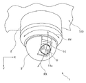
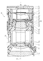
図1〜図13は、本発明の第1の実施形態を示す図である。このうち図1は、本実施形態の撮像装置の外観を概略的に示す外観斜視図である。図2は、図1の撮像装置における主要構成部(カメラユニット)を取り出して拡大して示す要部拡大斜視図である。図3は、図2の符号[3A]で示す面に沿う断面を同図矢印符号[3B]方向から見た縦断面図である。 1 to 13 are diagrams showing a first embodiment of the present invention. Among these, FIG. 1 is an external perspective view schematically showing the external appearance of the imaging apparatus of the present embodiment. FIG. 2 is an enlarged perspective view of the main part of the main component (camera unit) in the imaging apparatus of FIG. FIG. 3 is a longitudinal sectional view of a cross section taken along the plane indicated by reference numeral [3A] in FIG. 2 as viewed from the direction of arrow [3B].
まず、本発明の第1の実施形態の像振れ補正装置を適用した撮像装置の概略構成について、主に図1〜図3を用いて以下に簡単に説明する。 First, a schematic configuration of an imaging apparatus to which the image blur correction apparatus according to the first embodiment of the present invention is applied will be briefly described below mainly using FIGS.
本実施形態の像振れ補正装置を適用した撮像装置1は、例えば屋外や室内等の例えば天井や壁面等若しくは所定の柱又は台座等に対して固定して設置される。この撮像装置1は、設置場所において撮像対象とする領域や空間の状況を常時監視し得るように構成され、例えば定点観察や監視若しくは防犯等を目的とするネットワークカメラシステムに含まれる撮像装置の例示である。
The
撮像装置1は、図1に示すように、筐体2と、カバー部材3と、カメラユニット10等によって主に構成されている。
As shown in FIG. 1, the
筐体2は、例えば略円筒形状からなり、内部にカメラユニット10を収納配置する外装部材である。筐体2は、例えば天井100等に対して固設される。
The
カバー部材3は、例えば略ドーム形状(半球形状)からなり、上記筐体2の内部に収納されるカメラユニット10の一部及び撮像光学系の前面を覆い保護する保護部材である。また、カバー部材3は、カメラユニット10が筐体2の内部で、その撮像領域を変更するために撮像光学系の光軸Oの向く方向を変更する際の移動空間を確保する役目もしている。
The
カメラユニット10は、撮像光学系(図1では一部のみ図示。符号11a参照)及び撮像素子(図1では不図示。図3の符号17a参照)等を有して構成され、撮像機能を備える構成ユニットである。このカメラユニット10は、有線ケーブル又は無線等の通信手段を介して直接に、若しくは不図示のネットワーク等を介して、例えばデスクトップ型やノート型やタブレット型のパーソナルコンピュータ或いはスマートフォン等と呼ばれる携帯型通信用端末装置等の端末装置(不図示)と接続されている。なお、図示は省略しているが、上記端末装置には画像表示装置(不図示)が接続されており、この画像表示装置は、上記カメラユニット10によって取得される画像データや映像データを受けて画像や映像等を表示するほか、上記カメラユニット10を上記端末装置を用いて遠隔操作する際の制御画面(メニュー画面)等を表示することができるものである。
The
上記カメラユニット10は、上述したように、その撮像光学系の光軸Oの向く方向を、上記カバー部材3の内部空間内において変更し得るように構成されている。即ち、カメラユニット10は、図1に示す矢印RYに沿う方向であるパン方向の回動(横旋回であり図1のY軸周りの旋回である。その回動可能範囲は、例えば回転角度約360度)と、同図1に示す矢印RXに沿う方向であるチルト方向の回動(縦旋回であり図1のXY平面に沿う旋回である。その回動可能範囲は、例えば回転角度約90度〜180度程度)とが可能となるように、所定の回動駆動機構(不図示)が設けられている。
As described above, the
なお、カメラユニット10の回動駆動機構については、本発明とは直接関連しない部分であるので、従来一般に実用化されているものと同様のものが適用されているものとして、その図示及び説明は省略する。
Note that the rotation drive mechanism of the
カメラユニット10は、図2、図3に示すように、複数の光学レンズ(11a、12a、13a、14a、15a;図2では一部のみ図示。主に図3参照)によって構成される撮像光学系と、上記複数の光学レンズ(11a、12a、13a、14a、15a)を所定の群毎に保持する複数のレンズ群保持部材(11、12、13、14、15;図2では一部のみ図示。主に図3参照)と、これらのレンズ群保持部材のうちの一部を光軸Oに直交する平面(以下、XY平面という)内で移動させて像振れ補正動作に寄与する像振れ補正装置20(図2では不図示。図3参照)と、上記レンズ群保持部材のうちの他の一部を光軸Oに沿う方向に進退移動させて自動焦点調節(AF;auto focus)動作や変倍(ズーム;zoom)動作に寄与する駆動機構(不図示)と、撮像光学系を通過する撮像光束の光量調整を行う絞り機構18(図2では不図示。図3参照)と、撮像素子17aを搭載し当該撮像素子17aを駆動する撮像基板17(図2では不図示。図3参照)と、上記駆動機構(不図示)や撮像基板17等から延出される複数のフレキシブルプリント基板16等を含む電気部品等によって主に構成されている。
As shown in FIGS. 2 and 3, the
本実施形態において例示するカメラユニット10の撮像光学系は、第1レンズ群11a、第2レンズ群12a、第3レンズ群13a、第4レンズ群14a、第5レンズ群15aの5つのレンズ群によって構成されている。各レンズ群は、第1レンズ群保持部材11、第2レンズ群保持部材12、第3レンズ群保持部材13、第4レンズ群保持部材14、第5レンズ群保持部材15によってそれぞれ保持されている。
The imaging optical system of the
このうち、第4レンズ群保持部材14は、本実施形態の像振れ補正装置20を構成する主要構成部材である本体部材22及び蓋部材21によって挟持された形態となっている。そして、本実施形態の像振れ補正装置20は、後述する像振れ補正駆動ユニット25(図4等参照;符号26y、27yを含む)の作用によって、上記第4レンズ群保持部材14が保持する第4レンズ群14aを、撮像光学系の光軸Oに直交するXY平面内で移動させることによって像振れ補正を行う。つまり、本実施形態の像振れ補正装置20において、上記第4レンズ群保持部材14は、撮像光学系の一部の光学レンズを保持する可動枠である。そして、上記像振れ補正駆動ユニット25は、固定枠(本体部材22)に対し可動枠(第4レンズ群保持部材14)を駆動する駆動ユニットとして機能する(詳細後述)。
Among these, the 4th lens
なお、カメラユニット10の撮像光学系としては、光学倍率が例えば20〜30倍程度の高倍率のズーム光学系(zoom lens)が適用される。また、撮像光学系は、これに限られることはなく、例えば固定焦点タイプの光学系(例えば魚眼レンズ等)を適用してもよいし、可変焦点タイプ(バリフォーカルレンズ(varifocal lens)の光学系を適用してもよい。そして、光学倍率が50倍など、さらに高倍率のズーム光学系(zoom lens)であっても、もちろんよい。
As the imaging optical system of the
カメラユニット10の構成の概略は以上である。カメラユニット10において上述した以外の各種の構成部材、例えばAF動作やズーム動作に寄与する駆動機構(不図示)や上記絞り機構18及びフレキシブルプリント基板16等を含む各種の電気部品等、その他各種の構成部材については、本発明とは直接関連しない部分であるので、従来一般に実用化されているものと同様のものが適用されているものとして、その詳細説明は省略する。
The outline of the configuration of the
次に、本実施形態の像振れ補正装置20の構成を、主に図4〜図6を用いて以下に説明する。
Next, the configuration of the image
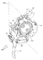
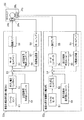
図4は、図2、図3に示すカメラユニットにおける主要構成部であって本実施形態の像振れ補正装置を取り出して示す外観斜視図である。図5は、図4の像振れ補正装置を分解して示す分解斜視図である。図6は、本実施形態の像振れ補正装置における像振れ補正制御部の主要構成要素を示すブロック構成図である。 FIG. 4 is an external perspective view showing the main components of the camera unit shown in FIGS. 2 and 3 and showing the image blur correction apparatus of the present embodiment. FIG. 5 is an exploded perspective view showing the image blur correction apparatus of FIG. 4 in an exploded manner. FIG. 6 is a block diagram showing the main components of the image blur correction control unit in the image blur correction apparatus of this embodiment.
本実施形態の像振れ補正装置20は、撮像光学系を構成する一部の光学レンズを撮像光学系の光軸Oに直交するXY平面内で移動させることによって像振れ補正を行う形態のいわゆるレンズシフト式の光学像振れ補正機構を具備するものである。なお、本実施形態の像振れ補正装置20の基本的な構成は、従来の同形態の像振れ補正装置と略同様である。
The image
本実施形態の像振れ補正装置20は、本体部材22と、蓋部材21と、像振れ補正駆動ユニット25と、撮像光学系を構成する一部の光学レンズ(第4レンズ群14a)と、これを保持する可動枠である第4レンズ群保持部材14等によって主に構成されている。
The image
本体部材22は、上記像振れ補正装置20における基本構成部材であり固定枠である。この本体部材22を基本として各種の構成部材がそれぞれ所定の部位に固定配置されている。本体部材22の略中央部分には、撮像光学系を透過する被写体光束を通過させるための開口22aが形成されている。
The
蓋部材21は、上記本体部材22の一面を覆うように配置され、上記本体部材22と当該蓋部材21との間に配設される各種の構成部材を保護し固定し支持するために設けられる。上記蓋部材21は、本体部材22に対して例えば複数(本実施形態では4本)のビス23を用いて固定されている。そのために、蓋部材21には複数(4箇所)のビス挿通穴21dが形成されている。これに対応させて、上記本体部材22には複数(4箇所)のビス穴22dが形成されている(図5参照)。また、上記蓋部材21は、その略中央部分に撮像光学系を透過する被写体光束を通過させるための開口21aが形成されている。
The
こうして、上記本体部材22と上記蓋部材21とがビス23等によって固定されて組み立てられた状態としたとき、両者(上記本体部材22と上記蓋部材21)の間には、上記第4レンズ群14aを保持する可動枠である第4レンズ群保持部材14が、光軸Oに直交するXY平面内で移動可能に配設されている。
Thus, when the
上記第4レンズ群保持部材14の略中央部分には略円形状の開口部が形成されており、この開口部に略円形状の第4レンズ群14aが固定配置されている。そして、上記第4レンズ群14aは、上記本体部材22の上記開口22aと、上記蓋部材21の上記開口21aとのそれぞれに対向する位置に配設されている。
A substantially circular opening is formed in a substantially central portion of the fourth lens
換言すると、第4レンズ群14aと本体部材22と蓋部材21とは、第4レンズ群14aの光軸Oと、上記開口22aの略中心軸と、上記開口21aの略中心軸との全てが略一致するように配設されている。
In other words, the
上述したように、上記本体部材22に対して上記第4レンズ群14aを保持する上記第4レンズ群保持部材14は、上記撮像光学系の光軸Oに直交するXY平面内で移動し得るように構成された可動枠である。そのために、まず、本体部材22と第4レンズ群保持部材14とは、複数(本実施形態では3本)の緊縮性を有する付勢ばね34を介して連結されている。これら複数の付勢ばね34は、光軸Oと平行な方向に伸縮し得るように、上記本体部材22と上記第4レンズ群保持部材14との間に、両者を引っ張るように架けられている(張架されている)。
As described above, the fourth lens
即ち、第4レンズ群保持部材14の所定の部位に形成された複数(3箇所)のバネ掛け部14c(図5参照)と、これに対応して本体部材22に設けられた同数(3箇所)のバネ掛け部(不図示)との間に、上記付勢ばね34の各端部が架けられている。これにより、可動枠である上記第4レンズ群保持部材14は、固定枠である上記本体部材22に対しては光軸Oに沿う方向に付勢されている。また、この状態において、上記第4レンズ群保持部材14は、光軸Oに直交するXY平面内で移動が可能となる自由度を有している。
That is, a plurality of (three places)
このように、上記本体部材22(固定枠)に対して上記第4レンズ群保持部材14(可動枠)が複数の付勢ばね34によって光軸Oに平行な方向に付勢されつつ連結されている状態において、両者間(上記本体部材22と上記第4レンズ群保持部材14との間)には、セラミックボール31が複数(少なくとも三個)介在している。このセラミックボール31は、上記本体部材22に対する上記第4レンズ群保持部材14の光軸Oに直交するXY平面内での移動を円滑化するために設けられるものである。ここで、セラミックボール31は、上記本体部材22に対し上記第4レンズ群保持部材14を移動可能に支持する支持部材として機能している。なお、本実施形態では、マグネットの影響を避けるためにセラミックボール31を使用しているが、マグネットの影響がない場合には、これに代えて、スチールボール(鋼球)を適用してもよい。
As described above, the fourth lens group holding member 14 (movable frame) is connected to the main body member 22 (fixed frame) while being biased in a direction parallel to the optical axis O by the plurality of biasing springs 34. In this state, a plurality (at least three) of
各セラミックボール31は次のように配設されている。即ち、上記本体部材22の上記開口22aの外周縁部領域に、複数(本実施形態では三箇所)のボール配設部22bが各所定の部位に形成されている。上記ボール配設部22bは、上記セラミックボール31を所定の範囲内で転動自在に収納し収納空間を形成すると共に、上記セラミックボール31の平面内での移動量を制限する支持部材配設部である。上記ボール配設部22bにおいて、その底面部となる部位、即ち上記本体部材22の平面(光軸Oに直交するXY平面)であって、上記セラミックボール31を受ける面には、例えばステンレス鋼などの金属平板部材等を用いて略矩形状に形成されたボール受板32が配設される。そして、上記本体部材22は、上記ボール受板32を囲うよう周縁部から光軸Oに沿う方向に向けて延出する壁面が形成されている(図5等参照)。これにより、上記ボール配設部22bは、上記底面部と上記壁面とによって、上記底面部の対向面を開口とする箱形状を形成している。
Each
一方、上述したように、上記本体部材22に対して上記第4レンズ群保持部材14を正規の所定の位置に重ねるように配設したときに、上記第4レンズ群保持部材14には、上記第4レンズ群14aが配設されている開口部の外周縁部領域であって、上記複数(本実施形態では三箇所)のボール配設部22bに各対向する各部位のそれぞれにボール受部14bが複数(本実施形態では三箇所)形成されている。各ボール受部14bにはそれぞれに、上記ボール受板32と同素材からなる金属平板部材等を用いた略矩形状に形成されたボール受板33が収納される。これら各ボール受板33は、この状態(即ち上記本体部材22と上記第4レンズ群保持部材14とを正規の所定の位置に重ねて配設した状態)としたときに、上記複数のボール配設部22bの各開口をそれぞれ塞ぐように配置される。これにより、このとき上記複数のボール配設部22b内には、上記セラミックボール31がそれぞれ一個ずつ収納された状態となる。このような構成とすることにより、上記セラミックボール31は、ボール配設部22bの内部において上記ボール受板32,33に挟持された状態で転動する。これによって、上記本体部材22(固定枠)に対する上記第4レンズ群保持部材14(可動枠)の光軸Oに直交するXY平面内での移動が円滑化されている。
On the other hand, as described above, when the fourth lens
なお、本実施形態においては、上記ボール配設部22b及び上記ボール受部14bを各3箇所設けた例を示している。この場合において、ボール配設部22b及び上記ボール受部14bは、開口22aの中心軸(即ち光軸Oと一致する仮想軸)を中心として、円周方向に略等間隔に配置されるのが望ましい。本実施形態においては、光軸Oを中心として角度略120度間隔となる各部位に、ボール配設部22b及び上記ボール受部14bを設けた例を示している。
In the present embodiment, an example is shown in which the
また、上記本体部材22においては、上記開口22aの外周縁領域に、例えば像振れ補正駆動ユニット25の一部を構成する部材である一対のコイル(26x、26y)が固定配置される構成としている。
Further, the
ここで、上記一対のコイル(26x、26y)のうち、一方のコイル(以下、X用コイルという)26xは、上記第4レンズ群保持部材14(可動枠)のX軸に沿う方向の移動に寄与する部材であってX軸に沿うように配置されている。また、上記一対のコイル(26x、26y)のうちの他方のコイル(以下、Y用コイルという)26yは、上記第4レンズ群保持部材14(可動枠)のY軸に沿う方向の移動に寄与する部材であってY軸に沿うように配置されている。 Here, of the pair of coils (26x, 26y), one coil (hereinafter referred to as X coil) 26x is used to move the fourth lens group holding member 14 (movable frame) in the direction along the X axis. It is a member that contributes and is arranged along the X-axis. The other coil (hereinafter referred to as Y coil) 26y of the pair of coils (26x, 26y) contributes to the movement of the fourth lens group holding member 14 (movable frame) in the direction along the Y axis. And is arranged along the Y-axis.
これに対応させて、上記第4レンズ群保持部材14には、上記一対のコイル(26x、26y)のそれぞれに対向する各部位に一対の磁石である一対のマグネット27x、27y(図5参照)が固設されている。つまり、各コイル26x、26yのそれぞれに対し、一対のマグネット27x、27yが配置されている。各マグネット27x、27yは、それぞれが二個一組で形成されている。各マグネット27x、27yのそれぞれは、磁極の向きが所定の方向となるように配置されている。
Correspondingly, the fourth lens
ここで、上記一対のマグネット27x、27yのうちの一方のマグネット(以下、X用マグネットという)27xは、上記X用コイル26xと協働して、上記第4レンズ群保持部材14(可動枠)のX軸に沿う方向の移動に寄与する部材である。X用マグネット27xを構成する二個のマグネットはX軸に沿う方向に磁極が反転するように並べて配置されている。また、上記一対のマグネット27x、27yのうちの他方のマグネット(以下、Y用マグネットという)27yは、上記Y用コイル26yと協働して、上記第4レンズ群保持部材14(可動枠)のY軸に沿う方向の移動に寄与する部材である。マグネット27yを構成する二個のマグネットはY軸に沿う方向に磁極が反転するように並べて配置されている。
Here, one magnet (hereinafter referred to as X magnet) 27x of the pair of magnets 27x and 27y cooperates with the
さらに、上記第4レンズ群保持部材14において、上記マグネット27の各近傍には、ホール素子等からなる磁気センサ28x、28y(図5参照)が配設されている。このうち一方の磁気センサ28xは、X軸に沿う方向の磁極変化を検出するX用磁気センサである。また、他方の磁気センサ28yは、Y軸に沿う方向の磁極変化を検出するY用磁気センサである。
Further, in the fourth lens
これらのマグネット27x、27y及び磁気センサ28x、28yは、当該像振れ補正駆動ユニット25の他の一部を構成する部材である。そして、これらマグネット(27x、27y)及び磁気センサ(28x、28y)は、上記第4レンズ群保持部材14の移動し得る平面内(XY平面内)における位置を検出する位置検出部を構成する。なお、位置検出部としては、後述する像振れ補正制御部(50x,50y)のホールアンプ56及び位置検出回路57等も含まれる(図6参照)。
The magnets 27x and 27y and the
このように、像振れ補正駆動ユニット25は、コイル(26x、26y)と、マグネット(27x、27y)と、磁気センサ(28x、28y)等を含んで構成されている。
As described above, the image blur
本実施形態の像振れ補正装置20は、上述した以外にも各種の構成部材が存在するが、それらの構成部材については本発明とは直接関連しないことから、その図示とその説明を省略する。
The image
このように構成された像振れ補正装置20は、図3に示すように、カメラユニット10の一部として所定の位置に固定配置されている。この場合において、像振れ補正装置20は、例えば複数のビス24(本実施形態では3本;図4、図5参照)を用いてカメラユニット10内における所定の固定部分に対して固定されている。
As shown in FIG. 3, the image
次に、本実施形態の像振れ補正装置20における電気的な構成部の主要部となる像振れ補正制御部(50x,50y)の概略構成について、図6を用いて以下に説明する。なお、図6において像振れ補正装置20をISユニットと表記している(ISは Image Stabilizationの意)。
Next, a schematic configuration of the image blur correction control unit (50x, 50y) that is a main part of the electrical configuration unit in the image
本実施形態の像振れ補正装置20における電気的構成部の主要部となり像振れ補正駆動ユニット25の駆動制御を行う制御部である像振れ補正制御部は、X用像振れ補正制御部50xと、Y用像振れ補正制御部50yとを有して構成されている。
The image blur correction control unit, which is a main part of the electrical components in the image
X用像振れ補正制御部50xは、X用磁気センサ28xからの出力を参照しながら、X用コイル26xへの駆動電流を制御することによって、上記第4レンズ群保持部材14(可動枠)のX軸に沿う方向への移動を制御する。Y用像振れ補正制御部50yは、Y用磁気センサ28yからの出力を参照しながら、Y用コイル26yへの駆動電流を制御することによって、上記第4レンズ群保持部材14(可動枠)のY軸に沿う方向への移動を制御する。なお、X用像振れ補正制御部50xとY用像振れ補正制御部50yとは全く同様に構成されている。例えば、像振れ補正制御部(50x、50y)は、パルス波のデューティー比を変化させて変調するパルス幅変調(pulse width modulation;PWM)により駆動電流の制御を行う。
The X image blur
X用像振れ補正制御部50xとY用像振れ補正制御部50yとは、それぞれが、ジャイロセンサ51と、手ブレ補正コントローラ52と、偏差演算器53と、サーボコントローラ54と、駆動アンプ55と、ホールアンプ56と、位置検出回路57と、自己診断用指示値コントローラ58と、自己診断用判定コントローラ59等を有して構成されている。
The X image blur
ジャイロセンサ51は、角速度や角加速度を検出することによって当該像振れ補正装置20が搭載される撮像装置1(カメラユニット10)のぶれ振動(装置ぶれ)を検出する検出センサである。ジャイロセンサ51によるぶれ振動検出結果は、手ブレ補正コントローラ52へと出力される。
The
手ブレ補正コントローラ52は、ジャイロセンサ51からの出力信号に基いて当該ぶれ振動を打ち消すためのぶれ補正値、即ち、像振れ補正装置(図6のISユニット)20をぶれ補正のために駆動する際の駆動量の演算を行う回路部である。手ブレ補正コントローラ52による駆動量演算結果は、偏差演算器53へと出力される。
Based on the output signal from the
また、これと同時に、偏差演算器53は、位置検出回路57からの出力信号を受領する。即ち、像振れ補正装置20の磁気センサ28x、28yからの出力信号が、当該像振れ補正制御部50x,50yのホールアンプ56へと入力されると、これを受けて、当該ホールアンプ56は信号増幅処理を行なう。ホールアンプ56によって増幅された信号は、位置検出回路57へと出力される。位置検出回路57は、これを受けて光軸Oに直交するXY平面内における第4レンズ群保持部材14(第4レンズ群14a)の本体部材22に対する位置を検出する。その検出結果が偏差演算器53へと出力される。このように、ホールアンプ56及び位置検出回路57は位置検出部の一部を構成している。
At the same time, the
偏差演算器53は、手ブレ補正コントローラ52からの出力信号と、位置検出回路27からの出力信号(詳細後述)とに基づいて偏差演算を行って、像振れ補正装置20への駆動信号を生成する回路部である。偏差演算器53による演算結果は、サーボコントローラ54へと出力される。
The
サーボコントローラ54は、偏差演算器53からの出力信号を受けて像振れ補正装置20の駆動制御信号、即ち第4レンズ群保持部材14(第4レンズ群14a)を目標位置(振れ振動を打ち消すための振れ補正位置)へと移動させるための駆動制御信号を生成する演算回路部である。サーボコントローラ54は、例えばマイコン等によって構成される。サーボコントローラ54により生成された駆動制御信号は駆動アンプ55へと出力される。
The
駆動アンプ55は、サーボコントローラ54からの駆動制御信号を受けて、これを増幅する増幅回路である。駆動アンプ55は、例えばPWM駆動回路等によって構成される。駆動アンプ55にて増幅された信号は、上記像振れ補正駆動ユニット25(図5等参照)へと送られて、所定の駆動制御、例えばコイル26x、26yを所定の駆動電流にて駆動する。
The
こうして、像振れ補正装置20が駆動されて(コイル26x、26yに所定の駆動電流が流されて)、第4レンズ群保持部材14(第4レンズ群14a)が、可動平面内で移動する。このときの第4レンズ群保持部材14(第4レンズ群14a)の位置は磁気センサ28x、28yにて検出されて位置検出回路57を介して、その位置情報が再度偏差演算器53へと入力される。そして、偏差演算器53により上記所定の演算がなされて、その演算結果がサーボコントローラ54へと出力される。そして、サーボコントローラ54は、再度像振れ補正装置20の駆動制御信号を生成し、この駆動制御信号に従って上記像振れ補正装置20の像振れ補正駆動ユニット25を駆動制御する。
Thus, the image
このように、像振れ補正装置20は、手ブレ補正コントローラ52による駆動量演算結果と、位置検出回路57によって検出された現在位置の位置検出結果とを比較しつつ、像振れ補正を行うフィードバック制御が行われている。本実施形態における像振れ補正装置20の上述した構成及び制御は、従来一般の像振れ補正装置における構成及び制御と略同様である。
As described above, the image
一方、本実施形態の像振れ補正装置20においては、予め設定されたタイミングで、予め設定された一連の規定動作を実行することによって、当該像振れ補正装置20自身が正常に動作しているか否か、不具合や異常が発生していないか否か、又は故障していないか否か、またさらに、正常に動作している場合においては、その劣化状態の程度が如何ほどか等、装置の状態を確認し判定するための自己診断モードを有している。
On the other hand, in the image
この自己診断モードでの動作を実行するタイミングは、具体的には、例えば毎日規定の時間毎に、又は所定の時間間隔毎(例えば24時間毎や一週間毎等の指定した時間間隔毎)等である。像振れ補正装置20を自己診断モードによって動作させる実行タイミングは、当該像振れ補正装置20を搭載する撮像装置1を制御する端末装置の制御部におけるプログラミングによって制御される。
Specifically, the timing of executing the operation in the self-diagnosis mode is, for example, every predetermined time every day or every predetermined time interval (for example, every 24 hours or every specified time interval such as every week), etc. It is. The execution timing at which the image
また、自己診断モードにおいて予め設定される一連の規定動作としては、例えば像振れ補正装置20を駆動させて、第4レンズ群保持部材14(第4レンズ群14a)を指示した目標位置へと移動させた際に、その目標位置を維持し得るか否か、その目標位置を維持する際の偏差が如何ほどかの確認を行って、当該像振れ補正装置20の状態を判定するといった一連の動作である。
Further, as a series of predetermined operations set in advance in the self-diagnosis mode, for example, the image
そのために、本実施形態の像振れ補正装置20においては、図6に示すように、また上述したように、自己診断用指示値コントローラ58と、自己診断用判定コントローラ59とを有している。
For this purpose, the image
自己診断用指示値コントローラ58は、当該像振れ補正装置20が自己診断モードで動作する際に、偏差演算器53に対して自己診断用指示値を出力する回路部である。ここで、自己診断用指示値は、可動枠を移動させる際の目標位置を表す移動目標値である。
The self-diagnosis
自己診断用判定コントローラ59は、当該像振れ補正装置20が自己診断モードで動作する際に、偏差演算器53からの出力、即ち偏差演算器53による演算結果(偏差)と、上記自己診断用指示値コントローラ58からの指示値データとを受けて、当該像振れ補正装置20の動作状態を判定する判定部として機能する回路部である。
When the image
具体的には、当該撮像装置1(カメラユニット10)が自己診断モードでの動作を開始すると、まず、自己診断用指示値コントローラ58から所定の位置(例えば中心位置)への駆動を指示する指示値が出力される。この指示信号は、偏差演算器53を介してサーボコントローラ54へと出力される。サーボコントローラ54では、指示信号に応じた駆動制御信号を生成し、これに従って像振れ補正駆動ユニット25を駆動制御する。
Specifically, when the imaging apparatus 1 (camera unit 10) starts operation in the self-diagnosis mode, first, an instruction for instructing driving from a self-diagnosis
位置検出回路57は、磁気センサ28x、28yの検出信号に基づいて、第4レンズ群保持部材14(第4レンズ群14a)の位置を検出し、その検出位置情報を偏差演算器53へと出力する。これにより、位置検出回路57は位置検出部の一部を構成している。
The
偏差演算器53では、上記指示値と上記検出位置情報とに基づいて偏差演算を行って、その演算結果を自己診断用判定コントローラ59へと出力する。これを受けた自己診断用判定コントローラ59は、偏差演算器53からの出力と、上記自己診断用指示値コントローラ58からの指示値データとを受けて自己の状態を診断し判定する。その判定結果は、像振れ補正制御部(50x、50y)からカメラユニット10の制御部(不図示)へと出力される。
The
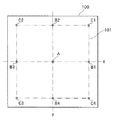
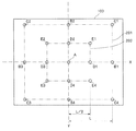
ここで、自己診断用指示値のデータは、例えばX−Y平面上の任意の点を指定するXY座標等である。自己診断用指示値は、具体的には図7に示すようなデータをとる。図7は、本実施形態の像振れ補正装置における自己診断用指示値のデータ(移動目標値)の具体例を示す図である。 Here, the self-diagnosis instruction value data is, for example, XY coordinates for designating an arbitrary point on the XY plane. Specifically, the instruction value for self-diagnosis takes data as shown in FIG. FIG. 7 is a diagram illustrating a specific example of self-diagnosis instruction value data (movement target value) in the image shake correction apparatus of the present embodiment.
図7において、符号100で示す実線で囲われる領域は、光軸Oに直交するXY平面内において、当該像振れ補正装置20の第4レンズ群保持部材14(第4レンズ群14a)が機械的に移動可能な範囲を示している。また、符号101で示す二点鎖線で囲われる領域は、像振れ補正で動作させる際の補正駆動範囲を示している。ここで、補正駆動範囲101は、移動駆動範囲100よりも内側になる。これは、例えば像振れ補正装置20における可動枠等の工作精度による機械的なばらつき等を考慮して、補正駆動範囲101が確実に確保されるようにするためである。
In FIG. 7, a region surrounded by a solid line denoted by
また、符号Aは、例えば第4レンズ群14aの中心点、即ち光軸Oに一致する点を示すものとする。像振れ補正装置20は、これが適用される撮像装置1(カメラユニット10)の起動中には、常に第4レンズ群14aの中心点(光軸O)と符号Aとを略一致させるように駆動制御される。このことから、符号Aで示す位置を基準指定位置というものとする。
The symbol A indicates, for example, the center point of the
符号B1〜B4は、移動駆動範囲100内において、それぞれX軸若しくはY軸上における目標点の例である。この場合において、例えば符号A位置から符号B1位置若しくは符号B3位置へと光軸Oを移動させるには、X用像振れ補正制御部50xを制御する。Y軸は動かないので、Y用像振れ補正制御部50yはその位置を保持するための制御を行う。同様に、例えば符号A位置から符号B2位置若しくは符号B4位置へと光軸Oを移動させるには、Y用像振れ補正制御部50yを制御し、X用像振れ補正制御部50xはその位置を保持するための制御を行う。
Reference numerals B <b> 1 to B <b> 4 are examples of target points on the X axis or Y axis, respectively, within the
符号C1〜C4は、移動駆動範囲100内における略四隅位置に目標点を設定する例である。この場合において、例えば符号A位置から符号C1位置〜C4位置のいずれかの位置に光軸Oを移動させるには、X用像振れ補正制御部50x及びY用像振れ補正制御部50yの双方を制御する必要がある。
Reference numerals C <b> 1 to C <b> 4 are examples in which target points are set at substantially four corner positions in the
自己診断モード時の移動目標点は、中心点から離れた位置を設定する程、またX軸及びY軸双方を駆動させる程、動作は厳しくなる。これは一般的に駆動機構の性能が中心が一番良く、中心から離れる程性能が劣化するためである。したがって、自己診断モードで動作させる際の移動目標点の選択により、診断基準の厳密度を設定できる。 The movement target point in the self-diagnosis mode becomes more severe as the position away from the center point is set and both the X axis and the Y axis are driven. This is because the performance of the drive mechanism is generally best at the center, and the performance deteriorates as the distance from the center increases. Therefore, the strictness of the diagnostic criteria can be set by selecting the movement target point when operating in the self-diagnosis mode.
その他の構成は、従来の像振れ補正装置と略同様である。したがって、上述していない構成については、本発明に直接関連しない部分であるから、その図示及び詳細説明は省略する。 Other configurations are substantially the same as those of the conventional image shake correction apparatus. Therefore, since the configuration not described above is a portion not directly related to the present invention, illustration and detailed description thereof are omitted.
次に、本実施形態の像振れ補正装置において、自己診断モードで動作させる際の作用を図8〜図13を用いて以下に説明する。 Next, the operation of the image blur correction apparatus according to the present embodiment when operated in the self-diagnosis mode will be described below with reference to FIGS.
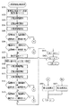
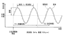
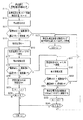
図8、図9、図11は、本実施形態の像振れ補正装置における自己診断モード時の処理シーケンスを示すフローチャートである。このうち、図8は、自己診断モード時の処理シーケンスのメインフローチャートである。図9は、図8の停止精度診断処理(ステップS1)及び駆動電流診断処理(ステップS2)の詳細な処理シーケンスを示すフローチャートである。図11は、図8の正弦波追従精度診断処理(ステップS3)の詳細な処理シーケンスを示すフローチャートである。 8, 9, and 11 are flowcharts showing a processing sequence in the self-diagnosis mode in the image blur correction apparatus of the present embodiment. Among these, FIG. 8 is a main flowchart of a processing sequence in the self-diagnosis mode. FIG. 9 is a flowchart showing a detailed processing sequence of the stop accuracy diagnosis process (step S1) and the drive current diagnosis process (step S2) of FIG. FIG. 11 is a flowchart showing a detailed processing sequence of the sinusoidal tracking accuracy diagnosis process (step S3) of FIG.
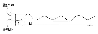
なお、図10、図12、図13は、図9及び図11の各フローチャートで示される各処理シーケンスを説明する説明図である。このうち、図10は、図9の停止精度診断処理(図8のステップS1の処理)の説明図である。図12は、図11の正弦波追従精度診断処理(図8のステップS3の処理)の説明図である。図13は、図12に示す駆動波と実体振動波との偏差の波形を示す図である。 10, 12, and 13 are explanatory diagrams for explaining the processing sequences shown in the flowcharts of FIGS. 9 and 11. Among these, FIG. 10 is an explanatory diagram of the stop accuracy diagnosis process of FIG. 9 (the process of step S1 of FIG. 8). FIG. 12 is an explanatory diagram of the sine wave follow-up accuracy diagnosis process of FIG. 11 (the process of step S3 of FIG. 8). FIG. 13 is a diagram illustrating a waveform of a deviation between the drive wave and the body vibration wave illustrated in FIG.
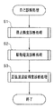
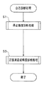
本実施形態の像振れ補正装置20が自己診断モードで動作する際には、図8に示すように、ステップS1の停止精度診断処理と、ステップS2の駆動電流診断処理と、ステップS3の正弦波追従精度診断処理が順次実行される。
When the image
図8のステップ1における停止精度診断処理は、図9に示すように、まず、ステップS11において、像振れ補正制御部(50x、50y)は、第4レンズ群14aの中心点を基準指定位置(図7の符号A)へと移動させる処理を行う。ここで同時に、指定位置を表す変数N=0を設定する。その後、ステップS12の処理に進む。
In the stop accuracy diagnosis process in
即ち、像振れ補正制御部(50x、50y)は、自己診断用指示値コントローラ58から指定位置を表す変数N=0に対応した基準指定位置((x座標,y座標)で示すと(x0,y0)(図7の符号A))を示す指示値を出力させる。この指示値信号は、偏差演算器53を介してサーボコントローラ54へと入力される。サーボコントローラ54は、これを受けて、入力された指示値信号に応じた駆動制御信号を生成し、これに従って像振れ補正装置20の像振れ補正駆動ユニット25を駆動制御する。その後、所定の時間(第1の規定時間T1)の間、第4レンズ群14aが安定するまで待機する。このとき、位置検出回路57は、磁気センサ28x、28yの検出信号に基づいて第4レンズ群14aの位置を検出し、その検出位置情報を偏差演算器53へ入力する。偏差演算器53では、上記指示値と上記検出位置情報とに基づいて偏差演算を行い、その演算結果をサーボコントローラ54へ出力する。サーボコントローラ54は、これを受けて、入力された指示値信号に応じた駆動制御信号を新たに生成して、像振れ補正駆動ユニット25を駆動制御する(以降繰り返し)。
That is, the image blur correction control unit (50x, 50y) indicates the reference designated position ((x coordinate, y coordinate) corresponding to the variable N = 0 representing the designated position from the self-diagnosis
このときの状況が、図10において符号T1で示す待機時間(第1の規定時間)である。図10に示す線図は、磁気センサ28x、28y及び位置検出回路57によって検出される第4レンズ群14aの現在位置の変動を示す図である。図10に示す駆動の初期期間、即ち待機時間T1の間においては、駆動されている第4レンズ群14aの現在位置が目標位置(この場合は基準指定位置A)に向けて変動し、その変動が安定していない状態にあることを示している。そして、待機時間T1が経過すると、第4レンズ群14aは安定状態になる。そこで、図9における次のステップS12の処理に進む。
The situation at this time is the standby time (first specified time) indicated by reference numeral T1 in FIG. The diagram shown in FIG. 10 is a diagram showing fluctuations in the current position of the
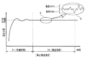
ステップS12において、像振れ補正制御部(50x、50y)は、停止精度測定処理を実行する。この処理は、図10に示す符号T2で示す測定時間(第2の規定時間)に実行される。この測定時間T2の期間中においては、目標位置(この場合は基準指定位置A)と現在位置との変動は、図10に示すように安定しており、両者は一見一致しているように見える。しかしながら、図10の符号Sで示す拡大図に見られるように、実際には微小な変動が見られる。そこで、このステップS12で実行される停止精度測定処理は、この微小変動のうちの最大値(偏差MAX)と最小値(偏差MIN)とを測定する処理である。この処理は、偏差演算器53において、位置検出回路57からの検出位置情報信号(現在位置情報)と上記指示値信号とに基づいて偏差演算を行うことにより求められる。ここで、求められた「偏差MAX」と「偏差MIN」は、自己診断用判定コントローラ59へと出力される。
In step S12, the image blur correction control unit (50x, 50y) executes a stop accuracy measurement process. This process is executed during the measurement time (second specified time) indicated by the symbol T2 shown in FIG. During the measurement time T2, the fluctuation between the target position (in this case, the reference designated position A) and the current position is stable as shown in FIG. 10, and the two seem to match at first glance. . However, as can be seen in the enlarged view indicated by the symbol S in FIG. Therefore, the stop accuracy measurement process executed in step S12 is a process for measuring the maximum value (deviation MAX) and the minimum value (deviation MIN) of the minute fluctuations. This process is obtained by the
次に、図9のステップS13において、像振れ補正制御部(50x、50y)は、上述のステップS12の処理にて求めた「偏差MAX」と「偏差MIN」とについて、所定の規格値±P0との比較を行う。ここで、規格値±P0は、当該像振れ補正装置20が正常に動作しているか否かの診断基準となる規格値である。つまり、規格値P0は、本像振れ補正装置20における正常動作の許容範囲を表すものといえる(以下、規格値について同様)。この規格値データは、例えば自己診断用判定コントローラ59内に予め記憶されているものとする。また、それ以外にも、例えば当該像振れ補正装置20の内部における他の部位に設けられている記憶媒体に予め記憶しておき、当該ステップS13の処理を行う際に、適宜読み出すような形態としてもよい。本実施形態において、具体的には、例えば規格値±P0=±8μmとする。
Next, in step S13 of FIG. 9, the image blur correction control unit (50x, 50y) determines a predetermined standard value ± P0 for “deviation MAX” and “deviation MIN” obtained in the processing of step S12 described above. Compare with. Here, the standard value ± P0 is a standard value serving as a diagnostic criterion for determining whether or not the image
上記ステップS13の処理にて、像振れ補正制御部(50x、50y)は、「偏差MAX > 規格値P0」または「偏差MIN < 規格値−(マイナス)P0」であることが自己診断用判定コントローラ59により確認された場合には、その判定結果をカメラユニット10の制御部(不図示)へと出力する。その後、ステップS25の処理へと進む。なお、偏差MAXと偏差MINで(偏差MAX)−(偏差MIN)を計算し、それに対応した規格P0’と比較しても良い。
In the processing of step S13, the image blur correction control unit (50x, 50y) determines that “deviation MAX> standard value P0” or “deviation MIN <standard value− (minus) P0”. If it is confirmed by 59, the determination result is output to a control unit (not shown) of the
ステップS25において、カメラユニット10の制御部(不図示)は、像振れ補正装置20からの上記判定結果を、上記有線ケーブル又は無線等の通信手段(不図示)、若しくはネットワーク等(不図示)を介して接続される端末装置(不図示)へと伝送する。これを受けた当該端末装置(不図示)は、画像表示装置(不図示)の表示画面上に、「第1注意表示」を表示する処理を実行する。その後、一連の処理を終了し、元の処理に戻る(リターン)。
In step S25, the control unit (not shown) of the
ここで、表示される「第1注意表示」の具体例としては、例えば撮像装置1(のカメラユニット10)の像振れ補正装置20に何らかの異常が発生しており修理若しくはメンテナンスが必要である旨の注意表示、あるいは不具合が生じている、若しくは故障である旨を通知する、若しくは修理や交換時期が近付いていることを告知する警告表示などである。
Here, as a specific example of the “first caution display” displayed, for example, the image
一方、上記ステップS13の処理にて、像振れ補正制御部(50x、50y)は、「偏差MAX > 規格値P0」または「偏差MIN < 規格値−(マイナス)P0」ではないことが自己診断用判定コントローラ59により確認された場合には、次のステップS14の処理へと進む。
On the other hand, in the process of step S13, the image blur correction control unit (50x, 50y) does not satisfy “deviation MAX> standard value P0” or “deviation MIN <standard value− (minus) P0”. If it is confirmed by the
ステップS14において、像振れ補正制御部(50x、50y)は、上述のステップS12の処理にて求めた「偏差MAX」と「偏差MIN」とについて、上記規格値±P0とは異なる所定の規格値±Q0との比較を行う。ここで、規格値±Q0は、当該像振れ補正装置20が正常に動作しているものの許容誤差を緩めた場合の診断基準となる規格値とする。したがって、規格値P0 > 規格値±Q0となるような値が設定される。本実施形態において、具体的には、例えば規格値±Q0=±5μmとする。
In step S14, the image blur correction control unit (50x, 50y) determines a predetermined standard value different from the standard value ± P0 for “deviation MAX” and “deviation MIN” obtained in the process of step S12. Compare with Q0. Here, the standard value ± Q0 is a standard value serving as a diagnostic standard when the image
なお、この規格値±Q0のデータも、例えば自己診断用判定コントローラ59内や、または当該像振れ補正装置20の内部の他の記憶媒体等に予め記憶されており、当該ステップS14の処理を行う際に適宜読み出すようにする。
The data of the standard value ± Q0 is also stored in advance in, for example, the self-
上記ステップS14の処理にて、像振れ補正制御部(50x、50y)は、「偏差MAX > 規格値Q0」または「偏差MIN < 規格値−(マイナス)Q0」であることが自己診断用判定コントローラ59により確認された場合には、その判定結果をカメラユニット10の制御部(不図示)へと出力する。その後、ステップS26の処理へと進む。
In the process of step S14, the image blur correction control unit (50x, 50y) determines that “deviation MAX> standard value Q0” or “deviation MIN <standard value− (minus) Q0”. If it is confirmed by 59, the determination result is output to a control unit (not shown) of the
ステップS26において、カメラユニット10の制御部(不図示)は、像振れ補正装置20からの上記判定結果を、上記有線ケーブル又は無線等の通信手段(不図示)、若しくはネットワーク等(不図示)を介して接続される端末装置(不図示)へと伝送する。これを受けた当該端末装置(不図示)は、画像表示装置(不図示)の表示画面上に、「第2注意表示」を表示する処理を実行する。その後、一連の処理を終了し、元の処理に戻る(リターン)。
In step S26, the control unit (not shown) of the
ここで、表示される「第2注意表示」の具体例としては、例えば撮像装置1(のカメラユニット10)の像振れ補正装置20には現時点で異常は発生していないものの、近い将来の修理若しくはメンテナンスが必要となる旨の注意表示、あるいは近い将来に異常若しくは故障等が発生する可能性を示唆する予告警告表示などである。
Here, as a specific example of the “second caution display” displayed, for example, the image
一方、上記ステップS14の処理にて、像振れ補正制御部(50x、50y)は、「偏差MAX > 規格値Q0」または「偏差MIN < 規格値−(マイナス)Q0」ではないことが自己診断用判定コントローラ59により確認された場合には、次のステップS15の処理へと進む。
On the other hand, in the processing of step S14, the image blur correction control unit (50x, 50y) is for self-diagnosis that “deviation MAX> standard value Q0” or “deviation MIN <standard value− (minus) Q0” is not satisfied. If it is confirmed by the
ステップS15において、像振れ補正制御部(50x、50y)は、指定位置を表す変数N=1に設定する。この場合において、基準指定位置Aから符号B(N)へと移動させるものとすると、目標位置B(N)=B1となる。同様に、基準指定位置Aから符号C(N)へと移動させるものとすると、目標位置C(N)=C1となる。 In step S15, the image blur correction control unit (50x, 50y) sets a variable N = 1 representing the designated position. In this case, if the reference designated position A is moved to the code B (N), the target position B (N) = B1. Similarly, if the reference designated position A is moved to the code C (N), the target position C (N) = C1.
続いて、ステップS16において、像振れ補正制御部(50x、50y)は、第4レンズ群14aの中心点を指定位置を表す変数N=1に対応した指定位置(例えば目標位置を図7の符号B1とする場合には座標(x1,y0)。また、目標位置を図7の符号C1とする場合には座標(x1,y1)へと移動させる処理を行う。この処理は、上述のステップS11の処理と略同様である。その後、ステップS17の処理に進む。
Subsequently, in step S16, the image blur correction control unit (50x, 50y) designates the center point of the
続いて、ステップS17において、像振れ補正制御部(50x、50y)は、停止精度測定処理を実行する。この処理は、上述のステップS12の処理と略同様である。その後、ステップS18の処理に進む。 Subsequently, in step S17, the image blur correction control unit (50x, 50y) executes a stop accuracy measurement process. This process is substantially the same as the process in step S12 described above. Thereafter, the process proceeds to step S18.
ステップS18において、像振れ補正制御部(50x、50y)は、上述のステップS17の処理にて求めた「偏差MAX」と「偏差MIN」とについて、所定の規格値±P1との比較を行う。ここで、規格値±P1は、上記規格値±P0と同様に、当該像振れ補正装置20が正常に動作しているか否かの診断基準となる規格値である。この規格値±P1のデータも、例えば自己診断用判定コントローラ59内や、または当該像振れ補正装置20の内部の他の記憶媒体等に予め記憶されており、当該ステップS18の処理を行う際に適宜読み出すようにする。
In step S18, the image blur correction control unit (50x, 50y) compares the “deviation MAX” and “deviation MIN” obtained in the process of step S17 described above with a predetermined standard value ± P1. Here, the standard value ± P1 is a standard value that serves as a diagnostic criterion for determining whether or not the image
一般に、駆動精度は、移動量が大きくなる程、つまり中心領域から離れた周辺領域へと移動させる程、低下する傾向がある。したがって、停止精度の基準値は、中心領域での駆動精度に比べて、周辺領域への移動の駆動精度は若干低めに設定しても良い。本実施形態においては、例えば基準指定位置Aでの停止精度の規格値±P0=±8μmとした場合に、基準指定位置Aより周辺領域(目標値B1、C1等)へ向けて移動させる際の停止精度の規格値±P1=±10μm等に設定すればよい。この処理は、上述のステップS13の処理と略同様である。 In general, the driving accuracy tends to decrease as the amount of movement increases, that is, as the moving amount moves to a peripheral region away from the central region. Therefore, the reference value for the stop accuracy may be set slightly lower for the drive accuracy of movement to the peripheral region than for the drive accuracy in the central region. In the present embodiment, for example, when the standard value ± P0 = ± 8 μm of the stop accuracy at the reference designated position A is set, when moving from the reference designated position A toward the peripheral region (target values B1, C1, etc.) The stop accuracy standard value ± P1 = ± 10 μm or the like may be set. This process is substantially the same as the process in step S13 described above.
即ち、ステップS18の処理にて、像振れ補正制御部(50x、50y)は、「偏差MAX > 規格値P1」または「偏差MIN < 規格値−(マイナス)P1」であることが自己診断用判定コントローラ59により確認された場合には、その判定結果をカメラユニット10の制御部(不図示)へと出力する。その後、ステップS25の処理へと進む。
That is, in the process of step S18, the image blur correction control unit (50x, 50y) determines that “deviation MAX> standard value P1” or “deviation MIN <standard value− (minus) P1”. When confirmed by the
ステップS25において、カメラユニット10の制御部(不図示)は、像振れ補正装置20からの上記判定結果を端末装置(不図示)へと伝送する。これを受けた当該端末装置(不図示)は、画像表示装置(不図示)の表示画面上に「第1注意表示」を表示する。その後、一連の処理を終了し、元の処理に戻る(リターン)。
In step S25, the control unit (not shown) of the
一方、上記ステップS18の処理にて、像振れ補正制御部(50x、50y)は、「偏差MAX > 規格値P1」または「偏差MIN < 規格値−(マイナス)P1」ではないことが自己診断用判定コントローラ59により確認された場合には、次のステップS19の処理へと進む。
On the other hand, in the process of step S18, the image blur correction control unit (50x, 50y) does not satisfy “deviation MAX> standard value P1” or “deviation MIN <standard value− (minus) P1”. If it is confirmed by the
ステップS19において、像振れ補正制御部(50x、50y)は、上述のステップS17の処理にて求めた「偏差MAX」と「偏差MIN」とについて、上記規格値±P1とは異なる所定の規格値±Q1との比較を行う。ここで、規格値±Q1は、上記規格値±Q0と同様に、当該像振れ補正装置20が正常に動作しているものの許容誤差を緩めた場合の診断基準となる規格値とする(規格値P1 > 規格値Q1)。また、規格値±Q1は周辺部の停止精度の基準値であるので、中心領域の停止精度の基準値である規格値±Q0に比べて若干低めに設定される。本実施形態においては、例えば規格値±Q0=±5μmとした場合に、規格値±Q1=±8μm等に設定すればよい。この処理は、上述のステップS14の処理と略同様である。
In step S19, the image blur correction control unit (50x, 50y) determines a predetermined standard value different from the standard value ± P1 for “deviation MAX” and “deviation MIN” obtained in the process of step S17 described above. Compare with ± Q1. Here, the standard value ± Q1 is a standard value that serves as a diagnostic reference when the image
なお、この規格値±Q1のデータも、例えば自己診断用判定コントローラ59内や、または当該像振れ補正装置20の内部の他の記憶媒体等に予め記憶されており、当該ステップS19の処理を行う際に適宜読み出すようにする。
The data of the standard value ± Q1 is also stored in advance in, for example, the self-
上記ステップS19の処理にて、像振れ補正制御部(50x、50y)は、「偏差MAX > 規格値Q1」または「偏差MIN < 規格値−(マイナス)Q1」であることが自己診断用判定コントローラ59により確認された場合には、その判定結果をカメラユニット10の制御部(不図示)へと出力する。その後、ステップS26の処理へと進む。
In the process of step S19, the image blur correction control unit (50x, 50y) determines that “deviation MAX> standard value Q1” or “deviation MIN <standard value− (minus) Q1”. If it is confirmed by 59, the determination result is output to a control unit (not shown) of the
ステップS26において、カメラユニット10の制御部(不図示)は、像振れ補正装置20からの上記判定結果を端末装置(不図示)へと伝送する。これを受けた当該端末装置(不図示)は、画像表示装置(不図示)の表示画面上に「第2注意表示」を表示する処理を実行する。その後、一連の処理を終了し、元の処理に戻る(リターン)。
In step S26, the control unit (not shown) of the
一方、上記ステップS19の処理にて、像振れ補正制御部(50x、50y)は、「偏差MAX > 規格値Q1」または「偏差MIN < 規格値−(マイナス)Q1」ではないことが自己診断用判定コントローラ59により確認された場合には、次のステップS20の処理へと進む。
On the other hand, in the process of step S19, the image blur correction control unit (50x, 50y) does not satisfy “deviation MAX> standard value Q1” or “deviation MIN <standard value− (minus) Q1”. If it is confirmed by the
ステップS20において、像振れ補正制御部(50x、50y)は、駆動電流測定処理を実行する。この駆動電流測定処理では、例えば駆動アンプ55の出力を確認する等の処理である。具体的には、例えばサーボコントローラ54の駆動デューティー等を検出する。したがって、この場合において、像振れ補正制御部(50x、50y)は駆動電流検出手段として機能する。ここで、駆動電流が大きい程、可動枠の移動量は大きくなることがわかる。その後、ステップS21の処理に進む。
In step S20, the image blur correction control unit (50x, 50y) executes a drive current measurement process. In this drive current measurement process, for example, the output of the
ステップS21において、像振れ補正制御部(50x、50y)は、上述のステップS20の駆動電流測定処理による駆動電流の測定結果について、所定の規格値I11との比較を行う。ここで、規格値I11は、当該像振れ補正装置20が正常に動作しているか否かの診断基準となる規格値である。この規格値I11のデータも、例えば自己診断用判定コントローラ59内や、または当該像振れ補正装置20の内部の他の記憶媒体等に予め記憶されており、当該ステップS20の処理を行う際に適宜読み出すようにする。
In step S21, the image blur correction control unit (50x, 50y) compares the measurement result of the drive current by the drive current measurement process in step S20 described above with a predetermined standard value I11. Here, the standard value I11 is a standard value serving as a diagnostic criterion for determining whether or not the image
上記ステップS21の処理にて、像振れ補正制御部(50x、50y)は、「駆動電流 <規格値I11」であることが確認された場合には、その判定結果をカメラユニット10の制御部(不図示)へと出力する。その後、ステップS25の処理へと進む。 In the process of step S21, when it is confirmed that “drive current <standard value I11”, the image blur correction control unit (50x, 50y) determines the determination result as the control unit ( (Not shown). Thereafter, the process proceeds to step S25.
ステップS25において、カメラユニット10の制御部(不図示)は、像振れ補正装置20からの上記判定結果を端末装置(不図示)へと伝送する。これを受けた当該端末装置(不図示)は、画像表示装置(不図示)の表示画面上に「第1注意表示」を表示する。その後、一連の処理を終了し、元の処理に戻る(リターン)。
In step S25, the control unit (not shown) of the
一方、ステップS21の処理にて、像振れ補正制御部(50x、50y)は、「駆動電流 <規格値I11」ではないことが確認された場合には、その判定結果をカメラユニット10の制御部(不図示)へと出力する。その後、ステップS22の処理へと進む。
On the other hand, in the process of step S21, when it is confirmed that the image blur correction control unit (50x, 50y) does not satisfy “drive current <standard value I11”, the determination result is sent to the control unit of the
ステップS22において、像振れ補正制御部(50x、50y)は、上述のステップS20の処理にて求めた駆動電流の測定結果について、上記規格値I11とは異なる所定の規格値I21との比較を行う。ここで、規格値I21は、当該像振れ補正装置20が正常に動作しているものの許容誤差を緩めた場合の診断基準となる規格値とする(規格値I11 > 規格値I21)。
In step S22, the image blur correction control unit (50x, 50y) compares the measurement result of the drive current obtained in the process of step S20 with a predetermined standard value I21 different from the standard value I11. . Here, the standard value I21 is a standard value that serves as a diagnostic criterion when the image
なお、この規格値I21のデータも、例えば自己診断用判定コントローラ59内や、または当該像振れ補正装置20の内部の他の記憶媒体等に予め記憶されており、当該ステップS22の処理を行う際に適宜読み出すようにする。
The data of the standard value I21 is also stored in advance in, for example, the self-
上記ステップS22の処理にて、像振れ補正制御部(50x、50y)は、「駆動電流 > 規格値I21」であることが確認された場合には、その判定結果をカメラユニット10の制御部(不図示)へと出力する。その後、ステップS26の処理へと進む。 In the process of step S22, when it is confirmed that “drive current> standard value I21”, the image blur correction control unit (50x, 50y) determines the determination result as the control unit ( (Not shown). Thereafter, the process proceeds to step S26.
ステップS26において、カメラユニット10の制御部(不図示)は、像振れ補正装置20からの上記判定結果を端末装置(不図示)へと伝送する。これを受けた当該端末装置(不図示)は、画像表示装置(不図示)の表示画面上に「第2注意表示」を表示する処理を実行する。その後、一連の処理を終了し、元の処理に戻る(リターン)。
In step S26, the control unit (not shown) of the
一方、上記ステップS22の処理にて、像振れ補正制御部(50x、50y)は、「駆動電流 > 規格値I21」ではないことが確認された場合には、次のステップS23の処理へと進む。 On the other hand, in the process of step S22, when it is confirmed that “drive current> standard value I21” is not satisfied, the image blur correction control unit (50x, 50y) proceeds to the process of the next step S23. .
ステップS23において、像振れ補正制御部(50x、50y)は、指定位置の変数Nについてインクリメントし(N+1)、次のステップS24に進む。 In step S23, the image blur correction control unit (50x, 50y) increments the variable N at the designated position (N + 1), and proceeds to the next step S24.
ステップS24において、像振れ補正制御部(50x、50y)は、指定位置の変数N=5であるか否かの確認を行う。ここで、N=5の確認を行うのは、当該自己診断モードにおいては、基準指定位置(図7の符号A)と指定する4つの指定位置(図7の符号B1〜B4若しくは符号C1〜C4)にて精度測定を行うようにするためである。したがって、測定指定位置の数はこれに限られることはない。指定位置を増減する場合には、ステップS24の処理にて変数Nに代入する数値を操作すればよい。 In step S24, the image blur correction controller (50x, 50y) checks whether or not the variable N = 5 at the designated position. Here, N = 5 is confirmed in the self-diagnosis mode in the four designated positions (reference numerals B1 to B4 or reference numerals C1 to C4 in FIG. 7) designated as the reference designated position (reference numeral A in FIG. 7). This is because the accuracy measurement is performed at (). Therefore, the number of measurement designated positions is not limited to this. In order to increase or decrease the designated position, a numerical value to be substituted into the variable N may be manipulated in the process of step S24.
上記ステップS24の処理にて、N=5である場合には、一連の処理を終了し、元の処理に戻る(リターン)。また、N=5が確認されない場合には、ステップS16の処理に戻り、以降の処理を繰り返す。 If N = 5 in the process of step S24, the series of processes is terminated and the process returns to the original process (return). If N = 5 is not confirmed, the process returns to step S16 and the subsequent processes are repeated.
図9の処理シーケンスを終了して図8に戻ると、図8における次のステップS3の正弦波追従精度診断処理が実行される。この正弦波追従精度診断処理の詳細は、図11に示す通りである。 When the processing sequence in FIG. 9 ends and the processing returns to FIG. 8, the sine wave tracking accuracy diagnosis processing in the next step S3 in FIG. 8 is executed. The details of the sine wave tracking accuracy diagnosis process are as shown in FIG.
まず、図11のステップS31において、像振れ補正制御部(50x、50y)は、第4レンズ群14aの中心点を基準指定位置(図7の符号A)へと移動させる処理を行う。ここで同時に、指定位置を表す変数N=0を設定する。このステップS31の処理は、図9のステップS11の処理と同様である。その後、ステップS32の処理に進む。
First, in step S31 in FIG. 11, the image blur correction control unit (50x, 50y) performs a process of moving the center point of the
ステップS32において、像振れ補正制御部(50x、50y)は、自己診断用指示値コントローラ58を制御して正弦波を生成し、これによって、第4レンズ群14aを駆動させる正弦波駆動を開始する。このとき、第4レンズ群14aは、上述のステップS31の処理により、指定された位置(現時点では基準指定位置A)にある。したがって、当該ステップS32において正弦波駆動が開始されると、第4レンズ群14aは、第4レンズ群14aは、指定された位置(現時点では基準指定位置A)を中心として振動する。そして、正弦波駆動を開始した後、所定の時間T1が経過するのを待機する。その後、ステップS33の処理に進む。
In step S32, the image blur correction control unit (50x, 50y) generates a sine wave by controlling the self-diagnosis
なお、上記ステップS32の処理にて、上記自己診断用指示値コントローラ58が駆動正弦波を生成するためには、例えば、予め自身(自己診断用指示値コントローラ58)の内部や若しくは当該像振れ補正装置20の内部の他の記憶媒体等に記憶されたテーブルデータを参照したり、又は当該自己診断用指示値コントローラ58自身が内部演算回路にて三角関数演算を行うことによって実現している。
In order for the self-diagnosis
ここで、図12に示す線図は、磁気センサ28x、28y及び位置検出回路57によって検出される第4レンズ群14aの現在位置の変動を示す図である。そして、図12で示す符号T1は、上記所定の時間T1であって、駆動開始後、測定開始前の待機時間T1である。本処理シーケンスにおいては、図12に示す駆動の初期期間、即ち待機時間T1の間は精度測定を待機し、当該待機時間T1の経過後に正弦波追従精度測定処理(図11のステップS33の処理)を開始する。図12に示すように、正弦波駆動による実体の振動(現在位置の変位)は、供給する正弦波(駆動波)よりも若干遅れて発生している。
Here, the diagram shown in FIG. 12 is a diagram showing a change in the current position of the
ステップS33において、像振れ補正制御部(50x、50y)は、偏差演算器53を制御して正弦波追従精度測定処理を実行する。この測定処理は、位置検出回路57からの検出位置情報信号(実体である第4レンズ群14aの現在位置情報)と、上記自己診断用指示値コントローラ58から出力される駆動用の正弦波(指示値)とに基づいて偏差演算を行うことにより求められる。その結果は、例えば図13に示すようになる。図13は、正弦波駆動を行った際の指示値と実体の現在地との偏差を示す線図である。上記ステップS33の処理にて実行される正弦波追従精度測定処理は、具体的には、図13の線図において示される最大値(偏差MAX)と最小値(偏差MIN)とを求める。ここで、求められた「偏差MAX」と「偏差MIN」は、自己診断用判定コントローラ59へと出力される。なお、当該精度測定処理は、図12の符号T2で示す所定の測定時間で行われる。所定の測定時間(T2)の経過後、ステップS34の処理に進む。
In step S33, the image blur correction control unit (50x, 50y) controls the
ステップS34において、像振れ補正制御部(50x、50y)は、正弦波駆動を停止する。 In step S34, the image blur correction control unit (50x, 50y) stops the sine wave drive.
続いて、ステップS35において、像振れ補正制御部(50x、50y)は、上述のステップS33の処理にて求めた「偏差MAX」と「偏差MIN」とについて、所定の規格値R0との比較を行う。ここで、規格値R0は、当該像振れ補正装置20が正常に動作しているか否かの診断基準となる規格値である。この規格値データは、例えば自己診断用判定コントローラ59内や、または当該像振れ補正装置20の内部の他の記憶媒体等に予め記憶されており、当該ステップS35の処理を行う際に適宜読み出すようにする。
Subsequently, in step S35, the image blur correction control unit (50x, 50y) compares the “deviation MAX” and “deviation MIN” obtained in the processing of step S33 described above with a predetermined standard value R0. Do. Here, the standard value R0 is a standard value serving as a diagnostic criterion for determining whether or not the image
上記ステップS35の処理において、像振れ補正制御部(50x、50y)は、「偏差MAX > 規格値R0」または「偏差MIN < 規格値−(マイナス)R0」であることが自己診断用判定コントローラ59により確認された場合には、その判定結果をカメラユニット10の制御部(不図示)へと出力する。その後、ステップS46の処理へと進む。
In the process of step S35, the image blur correction control unit (50x, 50y) determines that “deviation MAX> standard value R0” or “deviation MIN <standard value− (minus) R0” is satisfied. Is confirmed, the determination result is output to a control unit (not shown) of the
ステップS46において、カメラユニット10の制御部(不図示)は、像振れ補正装置20からの上記判定結果を端末装置(不図示)へと伝送する。これを受けた当該端末装置(不図示)は、画像表示装置(不図示)の表示画面上に、「第1注意表示」を表示する処理を実行する(図9のステップS25の処理と同様)。その後、一連の処理を終了し、元の処理に戻る(リターン)。
In step S46, the control unit (not shown) of the
一方、上記ステップS35の処理にて、像振れ補正制御部(50x、50y)は、「偏差MAX > 規格値R0」または「偏差MIN < 規格値−(マイナス)R0」ではないことが自己診断用判定コントローラ59により確認された場合には、次のステップS36の処理へと進む。
On the other hand, in the processing of step S35, the image blur correction control unit (50x, 50y) is for self-diagnosis that “deviation MAX> standard value R0” or “deviation MIN <standard value− (minus) R0” is not satisfied. If it is confirmed by the
ステップS36において、像振れ補正制御部(50x、50y)は、上述のステップS33の処理にて求めた「偏差MAX」と「偏差MIN」とについて、上記規格値R0とは異なる所定の規格値S0との比較を行う。ここで、規格値S0は、当該像振れ補正装置20が正常に動作しているものの許容誤差を緩めた場合の診断基準となる規格値とする。したがって、規格値R0 > 規格値S0となるような値が設定される。この規格値S0のデータも、例えば自己診断用判定コントローラ59内や、または当該像振れ補正装置20の内部の他の記憶媒体等に予め記憶されており、当該ステップS14の処理を行う際に適宜読み出すようにする。
In step S36, the image blur correction controller (50x, 50y) determines a predetermined standard value S0 that is different from the standard value R0 for the “deviation MAX” and “deviation MIN” obtained in the process of step S33. Compare with. Here, the standard value S0 is a standard value serving as a diagnostic reference when the image
上記ステップS36の処理にて、像振れ補正制御部(50x、50y)は、「偏差MAX > 規格値S0」または「偏差MIN < 規格値−(マイナス)S0」であることが自己診断用判定コントローラ59により確認された場合には、その判定結果をカメラユニット10の制御部(不図示)へと出力する。その後、ステップS47の処理へと進む。
In the process of step S36, the image blur correction controller (50x, 50y) determines that “deviation MAX> standard value S0” or “deviation MIN <standard value− (minus) S0”. If it is confirmed by 59, the determination result is output to a control unit (not shown) of the
ステップS47において、カメラユニット10の制御部(不図示)は、像振れ補正装置20からの上記判定結果を端末装置(不図示)へと伝送する。これを受けた当該端末装置(不図示)は、画像表示装置(不図示)の表示画面上に、「第2注意表示」を表示する処理を実行する(図9のステップS26の処理と同様)。その後、一連の処理を終了し、元の処理に戻る(リターン)。
In step S47, the control unit (not shown) of the
一方、上記ステップS36の処理にて、像振れ補正制御部(50x、50y)は、「偏差MAX > 規格値S0」または「偏差MIN < 規格値−(マイナス)S0」ではないことが自己診断用判定コントローラ59により確認された場合には、次のステップS37の処理へと進む。
On the other hand, in the process of step S36, the image blur correction control unit (50x, 50y) does not satisfy “deviation MAX> standard value S0” or “deviation MIN <standard value− (minus) S0”. If it is confirmed by the
ステップS37において、像振れ補正制御部(50x、50y)は、指定位置を表す変数N=1に設定する。 In step S37, the image blur correction control unit (50x, 50y) sets a variable N = 1 representing the designated position.
続いて、ステップS38において、像振れ補正制御部(50x、50y)は、第4レンズ群14aの中心点を指定位置N(例えば図7の符号B1)へと移動させる処理を行う。この処理は、上述のステップS11,S31の処理と略同様である。その後、ステップS39の処理に進む。
Subsequently, in step S38, the image blur correction control unit (50x, 50y) performs a process of moving the center point of the
ステップS39において、像振れ補正制御部(50x、50y)は、第4レンズ群14aの正弦波駆動を開始し、所定の時間T1が経過するのを待機する。その後、ステップS40の処理に進む。なお、このステップS39の処理は、上述のステップS32の処理と同様である。
In step S39, the image blur correction control unit (50x, 50y) starts sine wave driving of the
ステップS40において、像振れ補正制御部(50x、50y)は、偏差演算器53を制御して正弦波追従精度測定処理を所定の測定時間(図12の符号T2参照)実行する。そして、その所定の測定時間(T2)の経過後、ステップS41の処理に進む。なお、このステップS40の処理は、上述のステップS33の処理と同様である。
In step S40, the image blur correction control unit (50x, 50y) controls the
ステップS41において、像振れ補正制御部(50x、50y)は、正弦波駆動を停止する(上述のステップS34の処理と同じ)。 In step S41, the image blur correction control unit (50x, 50y) stops the sine wave drive (the same as the process in step S34 described above).
続いて、ステップS42において、像振れ補正制御部(50x、50y)は、上述のステップS40の処理にて求めた「偏差MAX」と「偏差MIN」とについて、所定規格値R1との比較を行う。ここで、規格値R1は、当該像振れ補正装置20が正常に動作しているか否かを診断する際の指定位置Nに対応する診断基準の規格値である。この規格値データも、例えば自己診断用判定コントローラ59内や、または当該像振れ補正装置20の内部の他の記憶媒体等に予め記憶されており、当該ステップS42の処理を行う際に適宜読み出すようにする。
Subsequently, in step S42, the image blur correction control unit (50x, 50y) compares the “deviation MAX” and “deviation MIN” obtained in the process of step S40 described above with the predetermined standard value R1. . Here, the standard value R1 is a standard value of a diagnostic standard corresponding to the designated position N when diagnosing whether or not the image
上記ステップS42の処理において、像振れ補正制御部(50x、50y)は、「偏差MAX > 規格値R1」または「偏差MIN < 規格値−(マイナス)R1」であることが自己診断用判定コントローラ59により確認された場合には、その判定結果をカメラユニット10の制御部(不図示)へと出力する。その後、ステップS46の処理へと進む。
In the processing of step S42, the image blur correction control unit (50x, 50y) determines that “deviation MAX> standard value R1” or “deviation MIN <standard value− (minus) R1” is satisfied. Is confirmed, the determination result is output to a control unit (not shown) of the
ステップS46において、カメラユニット10の制御部(不図示)は、像振れ補正装置20からの上記判定結果を端末装置(不図示)へと伝送する。これを受けた当該端末装置(不図示)は、画像表示装置(不図示)の表示画面上に、「第1注意表示」を表示する処理を実行する(図9のステップS25の処理と同様)。その後、一連の処理を終了し、元の処理に戻る(リターン)。
In step S46, the control unit (not shown) of the
一方、上記ステップS42の処理にて、像振れ補正制御部(50x、50y)は、「偏差MAX > 規格値R1」または「偏差MIN < 規格値−(マイナス)R1」ではないことが自己診断用判定コントローラ59により確認された場合には、次のステップS43の処理へと進む。
On the other hand, in the process of step S42, the image blur correction control unit (50x, 50y) does not satisfy “deviation MAX> standard value R1” or “deviation MIN <standard value− (minus) R1”. If it is confirmed by the
ステップS43において、像振れ補正制御部(50x、50y)は、上述のステップS40の処理にて求めた「偏差MAX」と「偏差MIN」とについて、上記規格値R1とは異なる所定の規格値S1との比較を行う。ここで、規格値S1は、当該像振れ補正装置20が正常に動作しているものの許容誤差を緩めた場合の診断基準となる規格値とする。したがって、規格値R1 > 規格値S1となるような値が設定される。この規格値S1のデータも、例えば自己診断用判定コントローラ59内や、または当該像振れ補正装置20の内部の他の記憶媒体等に予め記憶されており、当該ステップS43の処理を行う際に適宜読み出すようにする。
In step S43, the image blur correction control unit (50x, 50y) determines a predetermined standard value S1 that is different from the standard value R1 for the “deviation MAX” and “deviation MIN” obtained in the process of step S40. Compare with. Here, the standard value S1 is a standard value serving as a diagnostic standard when the image
上記ステップS43の処理にて、像振れ補正制御部(50x、50y)は、「偏差MAX > 規格値S1」または「偏差MIN < 規格値−(マイナス)S1」であることが自己診断用判定コントローラ59により確認された場合には、その判定結果をカメラユニット10の制御部(不図示)へと出力する。その後、ステップS47の処理へと進む。
In the process of step S43, the image blur correction controller (50x, 50y) determines that “deviation MAX> standard value S1” or “deviation MIN <standard value− (minus) S1”. If it is confirmed by 59, the determination result is output to a control unit (not shown) of the
ステップS47において、カメラユニット10の制御部(不図示)は、像振れ補正装置20からの上記判定結果を端末装置(不図示)へと伝送する。これを受けた当該端末装置(不図示)は、画像表示装置(不図示)の表示画面上に、「第2注意表示」を表示する処理を実行する(図9のステップS26の処理と同様)。その後、一連の処理を終了し、元の処理に戻る(リターン)。
In step S47, the control unit (not shown) of the
一方、上記ステップS43の処理にて、像振れ補正制御部(50x、50y)は、「偏差MAX > 規格値S1」または「偏差MIN < 規格値−(マイナス)S1」ではないことが自己診断用判定コントローラ59により確認された場合には、次のステップS44の処理へと進む。
On the other hand, in the process of step S43, the image blur correction control unit (50x, 50y) does not satisfy “deviation MAX> standard value S1” or “deviation MIN <standard value− (minus) S1”. If it is confirmed by the
ステップS44において、像振れ補正制御部(50x、50y)は、指定位置を表す変数Nについて、N+1の設定をする。 In step S44, the image blur correction control unit (50x, 50y) sets N + 1 for the variable N representing the designated position.
続いて、ステップS45において、像振れ補正制御部(50x、50y)は、指定位置N=5であるか否かの確認をする。ここで、N=5の確認を行っていることは、正弦波精度測定処理を5点(基準位置に加えて所定の四箇所)で行うためのカウンタとしているためである。 Subsequently, in step S45, the image blur correction controller (50x, 50y) checks whether or not the designated position N = 5. Here, the confirmation of N = 5 is because the counter is used for performing the sine wave accuracy measurement process at five points (predetermined four locations in addition to the reference position).
ここで、N=5であることが確認された場合には、一連の正弦波精度測定による診断処理を終了し、元の処理に戻る(リターン)。 Here, when it is confirmed that N = 5, a series of diagnostic processing by sine wave accuracy measurement is terminated, and the processing returns to the original processing (return).
また、N≠5であることが確認された場合には、上述のステップS38の処理に戻り、以降の処理を繰り返す。 If it is confirmed that N ≠ 5, the process returns to the above-described step S38, and the subsequent processes are repeated.
以上説明したように上記第1の実施形態によれば、第4レンズ群保持部材14(可動枠)に所定の動作、例えば所定の目標位置への移動とその位置を保持する動作や、所定の目標位置へ移動させその位置で正弦波駆動を行わせる動作等を実行して、その実行中の第4レンズ群保持部材14(可動枠)の位置検出を行って得られる位置検出結果が、予め規定された許容範囲内にあるか否かを判定することで、像振れ補正装置20が正常に動作しているか否かを判定する自己診断モードを備えて構成している。
As described above, according to the first embodiment, the fourth lens group holding member 14 (movable frame) has a predetermined operation, for example, a movement to a predetermined target position and an operation for holding the position, The position detection result obtained by performing the operation of moving to the target position and performing the sine wave drive at the position and detecting the position of the fourth lens group holding member 14 (movable frame) being executed is obtained in advance. A self-diagnosis mode for determining whether or not the image
そして、この自己診断モードによる動作を定期的、若しくは任意の時に実行することによって、像振れ補正装置20が正常動作しているか否かを確認することができる。
Then, by executing the operation in the self-diagnosis mode periodically or at any time, it is possible to confirm whether or not the image
また、装置の不具合、故障又は装置の劣化状態等を判定し、修理若しくは交換時期が近付いたことを告知する等によって、不具合が発生する可能性等を事前に的確に把握することができる。したがって、この像振れ補正装置を適用した撮像装置の信頼性の向上に寄与することができ、これを含むカメラシステムにおいて高い信頼性を確保できる。 In addition, it is possible to accurately grasp in advance the possibility of the occurrence of a failure by determining the failure or failure of the device or the deterioration state of the device and notifying that the time for repair or replacement is approaching. Therefore, it is possible to contribute to the improvement of the reliability of the imaging apparatus to which the image blur correction apparatus is applied, and high reliability can be ensured in a camera system including the imaging apparatus.
なお、図9の処理シーケンスにおいては、ステップS14の処理、ステップS19の処理、ステップS22の各処理を省略した形態で構成してもよい。同様に、図11の処理シーケンスにおいて、ステップS36の処理、ステップS43の処理、ステップS22の各処理を省略した形態で構成してもよい。 In addition, in the process sequence of FIG. 9, you may comprise with the form which abbreviate | omitted each process of step S14, the process of step S19, and step S22. Similarly, in the processing sequence of FIG. 11, the processing in step S36, the processing in step S43, and the processing in step S22 may be omitted.
また、本実施形態においては、像振れ補正装置20が自己診断モードで動作する際に、図8に示すステップS1の停止精度診断処理と、ステップS2の駆動電流診断処理と、ステップS3の正弦波追従精度診断処理とが順次実行されるものとして説明しているが、この例に限られることはない。例えば、像振れ補正装置が自己診断モードで動作する際には、停止精度診断処理及び駆動電流診断処理を実行するのみの形態でもよいし、また、正弦波追従精度診断処理を実行させるのみの形態であってもよい。
In this embodiment, when the image
例えば、次に説明する本発明の第2の実施形態は、像振れ補正装置を自己診断モードで動作させる際の制御処理を異ならせた場合の例示である。 For example, the second embodiment of the present invention described below is an example in the case where the control processing when operating the image blur correction apparatus in the self-diagnosis mode is different.
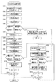
図14〜図17は、本発明の第2の実施形態の要旨を示す図である。このうち、図14は、本発明の第2の実施形態の像振れ補正装置における自己診断用指示値のデータ(移動目標値)を示す図である。図15、図16、図17は、本実施形態の像振れ補正装置における自己診断モード時の処理シーケンスを示すフローチャートである。このうち、図15は、本実施形態の像振れ補正装置における自己診断モード時の処理シーケンスを示すメインフローチャートである。図16は、図15の停止精度診断処理(ステップS1)の詳細な処理シーケンスを示すフローチャートである。図17は、図15の正弦波追従精度診断処理(ステップS3)の詳細な処理シーケンスを示すフローチャートである。 14-17 is a figure which shows the summary of the 2nd Embodiment of this invention. Among these, FIG. 14 is a diagram showing self-diagnosis instruction value data (movement target value) in the image blur correction apparatus according to the second embodiment of the present invention. FIGS. 15, 16, and 17 are flowcharts showing a processing sequence in the self-diagnosis mode in the image blur correction apparatus of the present embodiment. Among these, FIG. 15 is a main flowchart showing a processing sequence in the self-diagnosis mode in the image blur correction apparatus of the present embodiment. FIG. 16 is a flowchart showing a detailed processing sequence of the stop accuracy diagnosis process (step S1) of FIG. FIG. 17 is a flowchart showing a detailed processing sequence of the sinusoidal tracking accuracy diagnostic processing (step S3) of FIG.
本実施形態の像振れ補正装置及びこの像振れ補正装置を適用した撮像装置の基本的な構成は、上述の第1の実施形態と同様である。したがって、構成についての詳細説明は省略するが、以下の説明において各構成部材を示す際には同じ符号を用いるものとする。 The basic configuration of the image shake correction apparatus of the present embodiment and the imaging apparatus to which the image shake correction apparatus is applied is the same as that of the first embodiment described above. Therefore, although the detailed description about a structure is abbreviate | omitted, when showing each structural member in the following description, the same code | symbol shall be used.
また、本実施形態においては、図15に示すように、自己診断モードで動作させる際に、停止精度診断処理(図15のステップS1の処理)と正弦波追従精度診断処理(図15のステップS3の処理)とを実行するように制御されている。さらに、本実施形態においては、自己診断モード時の停止精度診断処理に適用する自己診断用指示値のデータ(移動目標値)は、図14に示すような形態としている。ここで、本実施形態における処理シーケンスにおいても、基本的には上述の実施形態一部の処理が異なるのみであり略同様の処理を示す場合には、同じ処理ステップ符号を用いるものとする。 Further, in the present embodiment, as shown in FIG. 15, when operating in the self-diagnosis mode, the stop accuracy diagnosis process (step S1 in FIG. 15) and the sine wave tracking accuracy diagnosis process (step S3 in FIG. 15). The process is controlled to be executed. Furthermore, in the present embodiment, the self-diagnosis instruction value data (movement target value) applied to the stop accuracy diagnosis processing in the self-diagnosis mode has a form as shown in FIG. Here, also in the processing sequence in the present embodiment, basically only the processing in the above-described embodiment is different, and the same processing step code is used when substantially the same processing is indicated.
即ち、本実施形態における自己診断用指示値のデータは、上述の第1の実施形態(図7)と同様に、例えばX−Y平面上の任意の点を指定するXY座標等である。本実施形態における自己診断用指示値の具体的は、図14に示すようなデータとしている。 That is, the self-diagnosis instruction value data in the present embodiment is, for example, XY coordinates for designating an arbitrary point on the XY plane, as in the first embodiment (FIG. 7). Specifically, the self-diagnosis instruction value in the present embodiment is data as shown in FIG.
図14において、符号100で示す実線で囲われる領域は、光軸Oに直交するXY平面内において、当該像振れ補正装置20の第4レンズ群保持部材14(第4レンズ群14a)が機械的に移動可能な範囲を示している(第1の実施形態の図7と同様)。また、符号201、202で示す二点鎖線で囲われる各領域は、像振れ補正で動作させる際の補正駆動範囲を示している。ここで、符号201の領域を第1補正駆動範囲というものとする。また、符号202の領域を第2補正駆動範囲というものとする。両補正駆動範囲201、202は、いずれも移動駆動範囲100よりも内側に設定されている。このうち、第1補正駆動範囲201は、上述の第1の実施形態における補正駆動範囲101と同様に、移動駆動範囲100よりも直近の内側領域に設定されている。この第1補正駆動範囲201は、像振れ補正装置20における可動枠等の工作精度による機械的なばらつき等を考慮して、第1補正駆動範囲201が確実に確保されるようにするための設定となっている。
In FIG. 14, an area surrounded by a solid line denoted by
また、第2補正移動範囲202は、第1補正移動範囲201に対してより狭い範囲となるように設定されている。例えば、第2補正移動範囲202によって示される枠線の一辺の長さを、第1補正移動範囲201の枠線の一辺の長さの二分の一となるように設定されている(詳細後述)。
Further, the second
図14において、符号Aは、例えば第4レンズ群14aの中心点、即ち光軸Oに一致する点を示す(第1の実施形態の図7と同様)。像振れ補正装置20は、これが適用される撮像装置1(カメラユニット10)の起動中には、常に第4レンズ群14aの中心点(光軸O)と符号Aとを略一致させるように駆動制御される。このことから、符号Aで示す位置を基準指定位置というものとする。この点において、上述の第1の実施形態と同様である。
In FIG. 14, a symbol A indicates, for example, a center point of the
図14において、符号B1〜B4は、移動駆動範囲100内における第1補正移動範囲201の枠線上の目標点の例である。即ち、目標点B1〜B4は、第1補正移動範囲201を示す枠線とX軸及びY軸のそれぞれに直交する交点である。この場合において、例えば符号A位置から符号B1位置若しくは符号B3位置へと光軸Oを移動させるには、X用像振れ補正制御部50xを制御する。Y軸は動かないので、Y用像振れ補正制御部50yはその位置を保持するための制御を行う。同様に、例えば符号A位置から符号B2位置若しくは符号B4位置へと光軸Oを移動させるには、Y用像振れ補正制御部50yを制御し、X用像振れ補正制御部50xはその位置を保持するための制御を行う。
In FIG. 14, reference signs B <b> 1 to B <b> 4 are examples of target points on the frame line of the first
図14において、符号C1〜C4は、移動駆動範囲100内における第1補正移動範囲201の枠線上の略四隅位置における目標点である。この場合において、例えば符号A位置から符号C1位置〜C4位置のいずれかの位置に光軸Oを移動させるには、X用像振れ補正制御部50x及びY用像振れ補正制御部50yの双方を制御する必要がある。
In FIG. 14, reference numerals C <b> 1 to C <b> 4 are target points at substantially four corner positions on the frame line of the first
さらに、図14において、符号D1〜D4は、移動駆動範囲100内における第2補正移動範囲202を示す枠線上の目標点である。即ち、目標点D1〜D4は、第2補正移動範囲202の枠線とX軸及びY軸のそれぞれに直交する交点である。この場合における制御は、符号B1〜B4と略同様である。
Further, in FIG. 14, reference signs D <b> 1 to D <b> 4 are target points on the frame line indicating the second corrected
なお、ここで、第2補正移動範囲202は、上述したように、第1補正移動範囲201よりも狭い範囲となるように設定されている。具体的には、例えば基準指定位置Aと目標点B1との距離を図14に示すように距離=Lとしたとき、基準指定位置Aと目標点D1との距離=L/2となるように設定している。その他の点についても同様である。
Here, as described above, the second
図14において、符号E1〜E4は、上述の符号C1〜C4と同様に、移動駆動範囲100内における第2補正移動範囲202における四隅位置の目標点である。この場合における制御は符号C1〜C4と略同様である。
In FIG. 14, reference symbols E <b> 1 to E <b> 4 are target points at the four corner positions in the second corrected
自己診断モード時の移動目標点は、中心点から離れた位置を設定する程、またX軸及びY軸双方を駆動させる程、動作は厳しくなる。これは一般的に駆動機構の性能が中心が一番良く、中心から離れる程性能が劣化するためである。 The movement target point in the self-diagnosis mode becomes more severe as the position away from the center point is set and both the X axis and the Y axis are driven. This is because the performance of the drive mechanism is generally best at the center, and the performance deteriorates as the distance from the center increases.
その他の構成は、上記第1の実施形態の像振れ補正装置と略同様である。なお、上述していない構成については、本発明に直接関連しない部分であり、上述の第1の実施形態と同様であるから、その図示及び詳細説明は省略する。 Other configurations are substantially the same as those of the image blur correction apparatus of the first embodiment. In addition, about the structure which is not mentioned above, since it is a part which is not directly related to this invention and is the same as that of the above-mentioned 1st Embodiment, the illustration and detailed description are abbreviate | omitted.
次に、本実施形態の像振れ補正装置において、自己診断モードで動作させる際の作用を図14〜図17を用いて以下に説明する。なお、本実施形態においては、上述の第1の実施形態で用いた説明図のうち図10、図12、図13等を援用し、具体的な図示は省略する。 Next, in the image shake correction apparatus of the present embodiment, the operation when operating in the self-diagnosis mode will be described below with reference to FIGS. In the present embodiment, FIG. 10, FIG. 12, FIG. 13 and the like among the explanatory diagrams used in the first embodiment described above are used, and specific illustrations are omitted.
本実施形態の像振れ補正装置20が自己診断モードで動作する際には、図15に示すように、ステップS1の停止精度診断処理と、ステップS3の正弦波追従精度診断処理が順次実行される。つまり、上述の第1の実施形態に比べると、駆動電流診断処理(図8のステップS2)の処理を省いている点で異なる。
When the image
即ち、図15のステップ1における停止精度診断処理の詳細は図16である。図16に示すように、まず、ステップS11において、像振れ補正制御部(50x、50y)は、第4レンズ群14aの中心点を基準指定位置(図7の符号A)へと移動させる処理を行う。ここで同時に、指定位置を表す変数N=0を設定する。その後、ステップS12の処理に進む。
That is, FIG. 16 shows details of the stop accuracy diagnosis process in
即ち、像振れ補正制御部(50x、50y)は、自己診断用指示値コントローラ58から指定位置を表す変数N=0に対応した基準指定位置((x座標,y座標)で示すと(x0,y0)であり図14の符号A)を示す指示値を出力させる。この指示値信号は、偏差演算器53を介してサーボコントローラ54へと入力される。サーボコントローラ54は、これを受けて、入力された指示値信号に応じた駆動制御信号を生成し、これに従って像振れ補正装置20の像振れ補正駆動ユニット25を駆動制御する。その後、所定の時間(第1の規定時間T1;図10参照)の間、第4レンズ群14aが安定するまで待機する。このとき、位置検出回路57は、磁気センサ28x、28yの検出信号に基づいて第4レンズ群14aの位置を検出し、その検出位置情報を偏差演算器53へ入力する。偏差演算器53では、上記指示値と上記検出位置情報とに基づいて偏差演算を行い、その演算結果をサーボコントローラ54へ出力する。サーボコントローラ54は、これを受けて、入力された指示値信号に応じた駆動制御信号を新たに生成して、像振れ補正駆動ユニット25を駆動制御する(以降繰り返し)。
That is, the image blur correction control unit (50x, 50y) indicates the reference designated position ((x coordinate, y coordinate) corresponding to the variable N = 0 representing the designated position from the self-diagnosis
このときの状況が、図10において符号T1で示す待機時間(第1の規定時間)である。図10に示す線図は、磁気センサ28x、28y及び位置検出回路57によって検出される第4レンズ群14aの現在位置の変動を示している。図10に示す駆動の初期期間、即ち待機時間T1の間においては、駆動されている第4レンズ群14aの現在位置が目標位置(この場合は基準指定位置A)に向けて変動し、その変動が安定していない状態にあることを示している。そして、待機時間T1が経過すると、第4レンズ群14aは安定状態になる。そこで、図16の次のステップS12の処理に進む。
The situation at this time is the standby time (first specified time) indicated by reference numeral T1 in FIG. The diagram shown in FIG. 10 shows the change in the current position of the
ステップS12において、像振れ補正制御部(50x、50y)は、停止精度測定処理を実行する。この処理は、図10に示す符号T2で示す測定時間(第2の規定時間)に実行される。この測定時間T2の期間中においては、目標位置(この場合は基準指定位置A)と現在位置との変動は、図10に示すように安定しており、両者は一見一致しているように見える。しかしながら、図10の符号Sで示す拡大図に見られるように、実際には微小な変動が見られる。そこで、このステップS12で実行される停止精度測定処理は、この微小変動のうちの最大値(偏差MAX)と最小値(偏差MIN)とを測定する処理である。この処理は、偏差演算器53において、位置検出回路57からの検出位置情報信号(現在位置情報)と上記指示値信号とに基づいて偏差演算を行うことにより求められる。ここで、求められた「偏差MAX」と「偏差MIN」は、自己診断用判定コントローラ59へと出力される。
In step S12, the image blur correction control unit (50x, 50y) executes a stop accuracy measurement process. This process is executed during the measurement time (second specified time) indicated by the symbol T2 shown in FIG. During the measurement time T2, the fluctuation between the target position (in this case, the reference designated position A) and the current position is stable as shown in FIG. 10, and the two seem to match at first glance. . However, as can be seen in the enlarged view indicated by the symbol S in FIG. Therefore, the stop accuracy measurement process executed in step S12 is a process for measuring the maximum value (deviation MAX) and the minimum value (deviation MIN) of the minute fluctuations. This process is obtained by the
次に、図15のステップS13において、像振れ補正制御部(50x、50y)は、上述のステップS12の処理にて求めた「偏差MAX」と「偏差MIN」とについて、所定の規格値±P0との比較を行う。ここで、規格値±P0は、当該像振れ補正装置20が正常に動作しているか否かの診断基準となる規格値である。この規格値データは、例えば自己診断用判定コントローラ59内に予め記憶されているものとする。また、それ以外にも、例えば当該像振れ補正装置20の内部における他の部位に設けられている記憶媒体に予め記憶しておき、当該ステップS13の処理を行う際に、適宜読み出すような形態としてもよい。本実施形態において、具体的には、例えば規格値±P0=±8μm等とする。
Next, in step S13 of FIG. 15, the image blur correction control unit (50x, 50y) determines a predetermined standard value ± P0 for “deviation MAX” and “deviation MIN” obtained in the processing of step S12 described above. Compare with. Here, the standard value ± P0 is a standard value serving as a diagnostic criterion for determining whether or not the image
上記ステップS13の処理にて、像振れ補正制御部(50x、50y)は、「偏差MAX > 規格値P0」または「偏差MIN < 規格値−(マイナス)P0」であることが自己診断用判定コントローラ59により確認された場合には、その判定結果をカメラユニット10の制御部(不図示)へと出力する。これを受けて、カメラユニット10の制御部(不図示)は、像振れ補正装置20に故障、異常発生等若しくはその兆候があるものと判定する。その後、ステップS27の処理へと進む。なお、偏差MAXと偏差MINで(偏差MAX)−(偏差MIN)を計算し、それに対応した規格P0’と比較しても良い。
In the processing of step S13, the image blur correction control unit (50x, 50y) determines that “deviation MAX> standard value P0” or “deviation MIN <standard value− (minus) P0”. If it is confirmed by 59, the determination result is output to a control unit (not shown) of the
ステップS27において、カメラユニット10の制御部(不図示)は、像振れ補正装置20を制御して、当該像振れ補正装置20の動作を停止させると共に、基準指定位置Aが維持されるように制御する。つまり、第4レンズ群14aの光軸を基準指定位置Aと一致する状態で維持するように静止させる。また、これと同時に、カメラユニット10の制御部(不図示)は、像振れ補正装置20からの上記判定結果を、上記有線ケーブル又は無線等の通信手段(不図示)若しくはネットワーク等(不図示)を介して接続される端末装置(不図示)へと伝送する。これを受けた当該端末装置(不図示)は、画像表示装置(不図示)の表示画面上に、「像振れ補正装置故障表示」を表示する処理等を実行する(フローチャートには不図示)。その後、一連の処理を終了し、元の処理に戻る(リターン)。
In step S <b> 27, the control unit (not shown) of the
上述したように、ステップS13の処理にて、現状の「偏差MAX」と「偏差MIN」とのうちの少なくとも一方が所定の規格値±P0を超えている場合には、像振れ補正装置20に故障、異常発生等若しくはその兆候があるものと判定されて、以降、像振れ補正装置20の動作を停止する。したがって、この場合、像振れ補正動作は実行されなくなるが、その一方で、像振れ補正駆動ユニット25は、第4レンズ群保持部材14を光軸中心である基準指定位置Aにて静止させるための動作制御を実行する。したがって、これにより、カメラユニット10は、画像データの取得動作を継続して行うことができる。つまり、カメラユニット10としての必要最小限の動作は確保されている。しかも、その場合に得られる画像データは、劣化の少ない良好なものとすることができる。なお、偏差が規格値±P0に対して著しく悪い場合には、エラー表示を出して像振れ補正駆動ユニット25の動作をも停止させる制御を行うことが望ましい。
As described above, when at least one of the current “deviation MAX” and “deviation MIN” exceeds the predetermined standard value ± P0 in the process of step S13, the image
一方、上記ステップS13の処理にて、像振れ補正制御部(50x、50y)は、「偏差MAX > 規格値P0」または「偏差MIN < 規格値−(マイナス)P0」ではないことが自己診断用判定コントローラ59により確認された場合には、次のステップS15の処理へと進む。
On the other hand, in the process of step S13, the image blur correction control unit (50x, 50y) does not satisfy “deviation MAX> standard value P0” or “deviation MIN <standard value− (minus) P0”. If it is confirmed by the
ステップS15において、像振れ補正制御部(50x、50y)は、指定位置を表す変数N=1に設定する。この場合において、基準指定位置Aから符号B(N)へと移動させるものとすると、目標位置B(N)=B1となる。同様に、基準指定位置Aから符号C(N)へと移動させるものとすると、目標位置C(N)=C1となる。 In step S15, the image blur correction control unit (50x, 50y) sets a variable N = 1 representing the designated position. In this case, if the reference designated position A is moved to the code B (N), the target position B (N) = B1. Similarly, if the reference designated position A is moved to the code C (N), the target position C (N) = C1.
続いて、ステップS16において、像振れ補正制御部(50x、50y)は、第4レンズ群14aの中心点を指定位置を表す変数N=1に対応した指定位置(例えば目標位置を図14の符号B1とする場合には座標(x1,y0)、また目標位置を図14の符号C1とする場合には座標(x1,y1))へと移動させる処理を行う。この処理は、上述のステップS11の処理と略同様である。その後、ステップS17の処理に進む。
Subsequently, in step S16, the image blur correction control unit (50x, 50y) designates the center point of the
続いて、ステップS17において、像振れ補正制御部(50x、50y)は、停止精度測定処理を実行する。この処理は、上述のステップS12の処理と略同様である。その後、ステップS18の処理に進む。 Subsequently, in step S17, the image blur correction control unit (50x, 50y) executes a stop accuracy measurement process. This process is substantially the same as the process in step S12 described above. Thereafter, the process proceeds to step S18.
ステップS18において、像振れ補正制御部(50x、50y)は、上述のステップS17の処理にて求めた「偏差MAX」と「偏差MIN」とについて、所定の規格値±P1との比較を行う。ここで、規格値±P1は、上記規格値±P0と同様に、当該像振れ補正装置20が正常に動作しているか否かの診断基準となる規格値である。この規格値±P1のデータも、例えば自己診断用判定コントローラ59内や、または当該像振れ補正装置20の内部の他の記憶媒体等に予め記憶されており、当該ステップS18の処理を行う際に適宜読み出すようにする。
In step S18, the image blur correction control unit (50x, 50y) compares the “deviation MAX” and “deviation MIN” obtained in the process of step S17 described above with a predetermined standard value ± P1. Here, the standard value ± P1 is a standard value that serves as a diagnostic criterion for determining whether or not the image
一般に、駆動精度は、移動量が大きくなる程、つまり中心領域から離れた周辺領域へと移動させる程、低下する傾向がある。したがって、停止精度の基準値は、中心領域での駆動精度に比べて、周辺領域への移動の駆動精度は若干低めに、つまり、規格値P1>規格値P0等となるように設定しても良い。本実施形態においては、例えば基準指定位置Aでの停止精度の規格値±P0=±8μmとした場合に、基準指定位置Aより周辺領域(目標値B1、C1等)へ向けて移動させる際の停止精度の規格値±P1=±10μm等に設定する。このステップS18の処理は、上述のステップS13の処理と略同様である。 In general, the driving accuracy tends to decrease as the amount of movement increases, that is, as the moving amount moves to a peripheral region away from the central region. Therefore, the reference value of the stop accuracy may be set so that the drive accuracy of movement to the peripheral region is slightly lower than the drive accuracy in the central region, that is, the standard value P1> the standard value P0. good. In the present embodiment, for example, when the standard value ± P0 = ± 8 μm of the stop accuracy at the reference designated position A is set, when moving from the reference designated position A toward the peripheral region (target values B1, C1, etc.) The standard value of stopping accuracy ± P1 = ± 10 μm or the like is set. The process in step S18 is substantially the same as the process in step S13 described above.
即ち、ステップS18の処理にて、像振れ補正制御部(50x、50y)は、「偏差MAX > 規格値P1」または「偏差MIN < 規格値−(マイナス)P1」であることが自己診断用判定コントローラ59により確認された場合には、ステップS51の処理へと進む。
That is, in the process of step S18, the image blur correction control unit (50x, 50y) determines that “deviation MAX> standard value P1” or “deviation MIN <standard value− (minus) P1”. If it is confirmed by the
即ち、上記ステップS18の処理において、目標点B1又はC1への移動時における「偏差MAX」と「偏差MIN」とのうちの少なくとも一方が所定の規格値±P1を超えている場合には、像振れ補正装置20に故障、異常発生等若しくはその兆候があるものと判定されて、上記ステップS51の処理へと進む。
That is, in the process of step S18, when at least one of “deviation MAX” and “deviation MIN” during movement to the target point B1 or C1 exceeds a predetermined standard value ± P1, It is determined that the
ステップS51においては、さらに、他の目標点、例えば像振れ補正制御部(50x、50y)は、中心領域に近い側の指定位置として、目標点D(N)又はE(N)への移動を試行する。つまり、上記ステップS51においては、像振れ補正制御部(50x、50y)は、第4レンズ群14aの中心点を指定位置変数N=1に対応した指定位置(例えば目標位置を図14の符号D1とする場合には座標(x1/2,y0)、また目標位置を図14の符号E1とする場合には座標(x1/2,y1/2))へと移動させる処理を行う。この処理は、上述のステップS16の処理と略同様である。その後、ステップS52の処理に進む。
In step S51, another target point, for example, the image blur correction control unit (50x, 50y), moves to the target point D (N) or E (N) as the designated position closer to the central region. Try. In other words, in step S51, the image blur correction control unit (50x, 50y) designates the center point of the
続いて、ステップS52において、像振れ補正制御部(50x、50y)は、停止精度測定処理を実行する。この処理は、上述のステップS12、S17の処理と略同様である。その後、ステップS53の処理に進む。 Subsequently, in step S52, the image blur correction control unit (50x, 50y) executes a stop accuracy measurement process. This process is substantially the same as the processes in steps S12 and S17 described above. Thereafter, the process proceeds to step S53.
ステップS53において、像振れ補正制御部(50x、50y)は、上述のステップS52の処理にて求めた「偏差MAX」と「偏差MIN」とについて、所定の規格値±P1との比較を行う。この処理は、上述のステップS13、S18の処理と略同様である。ここで、目標点D(N)又はE(N)への移動時における「偏差MAX」と「偏差MIN」とのうちの少なくとも一方が所定の規格値±P1を超えている場合には、像振れ補正装置20に故障、異常発生等若しくはその兆候があるものと判定されて、上記ステップS27の処理へと進む。
In step S53, the image blur correction control unit (50x, 50y) compares the “deviation MAX” and “deviation MIN” obtained in the processing of step S52 described above with a predetermined standard value ± P1. This process is substantially the same as the processes in steps S13 and S18 described above. Here, when at least one of “deviation MAX” and “deviation MIN” during movement to the target point D (N) or E (N) exceeds a predetermined standard value ± P1, It is determined that the
そして、ステップS27において、カメラユニット10の制御部(不図示)は、像振れ補正装置20を制御して、当該像振れ補正装置20の動作を停止させると共に、基準指定位置Aが維持されるように制御する。つまり、第4レンズ群14aの光軸を基準指定位置Aと一致する状態で維持するように静止させる。また、これと同時に、カメラユニット10の制御部(不図示)は、像振れ補正装置20からの上記判定結果を、上記有線ケーブル又は無線等の通信手段(不図示)若しくはネットワーク等(不図示)を介して接続される端末装置(不図示)へと伝送する。これを受けた当該端末装置(不図示)は、画像表示装置(不図示)の表示画面上に、「像振れ補正装置故障表示」を表示する処理等を実行する(フローチャートには不図示)。その後、一連の処理を終了し、元の処理に戻る(リターン)。
In step S27, the control unit (not shown) of the
一方、上記ステップS53の処理にて、像振れ補正制御部(50x、50y)は、「偏差MAX > 規格値P1」または「偏差MIN < 規格値−(マイナス)P1」ではないことが自己診断用判定コントローラ59により確認された場合には、次のステップS54の処理へと進む。
On the other hand, in the processing of step S53, the image blur correction control unit (50x, 50y) does not satisfy “deviation MAX> standard value P1” or “deviation MIN <standard value− (minus) P1”. If it is confirmed by the
ステップS54において、カメラユニット10の制御部(不図示)は、像振れ補正装置20による像振れ補正動作において行う指定方向の移動は、移動量の少ない領域、即ち第2補正移動範囲202において行うように、振れ補正移動量を制限する。その後、ステップS23の処理に進む。
In step S <b> 54, the control unit (not shown) of the
ステップS23において、像振れ補正制御部(50x、50y)は、指定位置の変数Nについてインクリメントし(N+1)、次のステップS24に進む。 In step S23, the image blur correction control unit (50x, 50y) increments the variable N at the designated position (N + 1), and proceeds to the next step S24.
ステップS24において、像振れ補正制御部(50x、50y)は、指定位置の変数N=5であるか否かの確認を行う。ここで、N=5の確認を行うのは、当該自己診断モードにおいては、基準指定位置(図14の符号A)と指定する4つの指定位置(図14の符号B1〜B4若しくは符号C1〜C4、符号D1〜D4、符号E1〜E4)にて精度測定を行うようにするためである(つまり、4回処理を繰り返すためである)。したがって、測定指定位置の数はこれに限られることはない。指定位置を増減する場合には、ステップS24の処理にて変数Nに代入する数値を増減操作すればよい。 In step S24, the image blur correction controller (50x, 50y) checks whether or not the variable N = 5 at the designated position. Here, N = 5 is confirmed in the self-diagnosis mode in the four designated positions (reference numerals B1 to B4 or reference numerals C1 to C4 in FIG. 14) and the designated reference position (reference numeral A in FIG. 14). , D1 to D4, and E1 to E4) to measure the accuracy (that is, to repeat the process four times). Therefore, the number of measurement designated positions is not limited to this. In order to increase or decrease the designated position, the numerical value assigned to the variable N may be increased or decreased in the process of step S24.
上記ステップS24の処理にて、N=5である場合には、一連の処理を終了し、元の処理に戻る(リターン)。また、N=5が確認されない場合には、ステップS51の処理に戻り、以降の処理を繰り返す。 If N = 5 in the process of step S24, the series of processes is terminated and the process returns to the original process (return). If N = 5 is not confirmed, the process returns to step S51 and the subsequent processes are repeated.
他方、上記ステップS18の処理にて、像振れ補正制御部(50x、50y)は、「偏差MAX > 規格値P1」または「偏差MIN < 規格値−(マイナス)P1」ではないことが自己診断用判定コントローラ59により確認された場合には、次のステップS28の処理へと進む。
On the other hand, in the process of step S18, the image blur correction control unit (50x, 50y) does not satisfy “deviation MAX> standard value P1” or “deviation MIN <standard value− (minus) P1”. If it is confirmed by the
ステップS28において、像振れ補正制御部(50x、50y)は、上述のステップS18の処理による判定結果に基いて、像振れ補正装置20における指定位置方向の移動、即ち基準指定位置Aから目標点B1又はC1への移動には問題がないものと判定する。その後、次のステップS23の処理へと進む。
In step S28, the image blur correction controller (50x, 50y) moves in the designated position direction in the image
ステップS23において、像振れ補正制御部(50x、50y)は、指定位置の変数Nについてインクリメントし(N+1)、次のステップS24に進む。 In step S23, the image blur correction control unit (50x, 50y) increments the variable N at the designated position (N + 1), and proceeds to the next step S24.
ステップS24において、像振れ補正制御部(50x、50y)は、指定位置の変数N=5であるか否かの確認を行う。ここで、N=5の確認を行うのは、当該自己診断モードにおいては、基準指定位置(図7の符号A)と指定する4つの指定位置(図7の符号B1〜B4若しくは符号C1〜C4)にて精度測定を行うようにするためである。したがって、測定指定位置の数はこれに限られることはない。指定位置を増減する場合には、ステップS24の処理にて変数Nに代入する数値を操作すればよい。 In step S24, the image blur correction controller (50x, 50y) checks whether or not the variable N = 5 at the designated position. Here, N = 5 is confirmed in the self-diagnosis mode in the four designated positions (reference numerals B1 to B4 or reference numerals C1 to C4 in FIG. 7) designated as the reference designated position (reference numeral A in FIG. 7). This is because the accuracy measurement is performed at (). Therefore, the number of measurement designated positions is not limited to this. In order to increase or decrease the designated position, a numerical value to be substituted into the variable N may be manipulated in the process of step S24.
上記ステップS24の処理にて、N=5である場合には、一連の処理を終了し、元の処理に戻る(リターン)。また、N=5が確認されない場合には、ステップS16の処理に戻り、以降の処理を繰り返す。 If N = 5 in the process of step S24, the series of processes is terminated and the process returns to the original process (return). If N = 5 is not confirmed, the process returns to step S16 and the subsequent processes are repeated.
こうして図16の処理シーケンスを終了して図15に戻ると、図15における次のステップS3の正弦波追従精度診断処理が実行される。この正弦波追従精度診断処理の詳細は、図17に示す通りである。なお、図17のフローチャートは、上述の第1の実施形態における図11と同様の処理ステップを含む。したがって、図17において、図11と同様の処理ステップには同じ符号を付して説明する。 When the processing sequence in FIG. 16 is completed and the processing returns to FIG. 15, the sine wave tracking accuracy diagnosis processing in the next step S3 in FIG. 15 is executed. The details of the sine wave tracking accuracy diagnosis process are as shown in FIG. Note that the flowchart in FIG. 17 includes the same processing steps as in FIG. 11 in the first embodiment described above. Therefore, in FIG. 17, the same processing steps as those in FIG.
まず、図11のステップS31において、像振れ補正制御部(50x、50y)は、第4レンズ群14aの中心点を基準指定位置(図7の符号A)へと移動させる処理を行う。同時に、指定位置を表す変数N=0を設定する。このステップS31の処理は、図9、図11、図16のステップS11の処理と同様である。その後、ステップS32の処理に進む。
First, in step S31 in FIG. 11, the image blur correction control unit (50x, 50y) performs a process of moving the center point of the
ステップS32において、像振れ補正制御部(50x、50y)は、自己診断用指示値コントローラ58を制御して正弦波を生成し、これによって、第4レンズ群14aを駆動させる正弦波駆動を開始する。このとき、第4レンズ群14aは、上述のステップS31の処理により、指定された位置(現時点では基準指定位置A)にある。したがって、当該ステップS32において正弦波駆動が開始されると、第4レンズ群14aは、第4レンズ群14aは、指定された位置(現時点では基準指定位置A)を中心として振動する。そして、正弦波駆動を開始した後、所定の時間T1(図12参照)が経過するのを待機する。その後、ステップS33の処理に進む。
In step S32, the image blur correction control unit (50x, 50y) generates a sine wave by controlling the self-diagnosis
なお、上記ステップS32の処理にて、上記自己診断用指示値コントローラ58が駆動正弦波を生成するためには、例えば、予め自身(自己診断用指示値コントローラ58)の内部や若しくは当該像振れ補正装置20の内部の他の記憶媒体等に記憶されたテーブルデータを参照したり、又は当該自己診断用指示値コントローラ58自身が内部演算回路にて三角関数演算を行うことによって実現している。
In order for the self-diagnosis
ここで、磁気センサ28x、28y及び位置検出回路57によって検出される第4レンズ群14aの現在位置の変動は、上述した図12と同様である。図12で示す符号T1は、上記所定の時間T1であって、駆動開始後、測定開始前の待機時間T1である。本処理シーケンスにおいては、図12に示す駆動の初期期間、即ち待機時間T1の間は精度測定を待機し、当該待機時間T1の経過後に正弦波追従精度測定処理(図11のステップS33の処理)を開始する。図12に示すように、正弦波駆動による実体の振動(現在位置の変位)は、供給する正弦波(駆動波)よりも若干遅れて発生している。
Here, the change in the current position of the
ステップS33において、像振れ補正制御部(50x、50y)は、偏差演算器53を制御して正弦波追従精度測定処理を実行する。この測定処理は、位置検出回路57からの検出位置情報信号(実体である第4レンズ群14aの現在位置情報)と、上記自己診断用指示値コントローラ58から出力される駆動用の正弦波(指示値)とに基づいて偏差演算を行うことにより求められる。その結果は、例えば図13に示すようになる。図13は、正弦波駆動を行った際の指示値と実体の現在地との偏差を示す線図である。上記ステップS33の処理にて実行される正弦波追従精度測定処理は、具体的には、図13の線図において示される最大値(偏差MAX)と最小値(偏差MIN)とを求める。ここで、求められた「偏差MAX」と「偏差MIN」は、自己診断用判定コントローラ59へと出力される。なお、当該精度測定処理は、図12の符号T2で示す所定の測定時間で行われる。所定の測定時間(T2)の経過後、ステップS34の処理に進む。
In step S33, the image blur correction control unit (50x, 50y) controls the
ステップS34において、像振れ補正制御部(50x、50y)は、正弦波駆動を停止する。 In step S34, the image blur correction control unit (50x, 50y) stops the sine wave drive.
続いて、ステップS35において、像振れ補正制御部(50x、50y)は、上述のステップS33の処理にて求めた「偏差MAX」と「偏差MIN」とについて、所定の規格値±R0との比較を行う。ここで、規格値±R0は、当該像振れ補正装置20が正常に動作しているか否かの診断基準となる規格値である。この規格値データは、例えば自己診断用判定コントローラ59内や、または当該像振れ補正装置20の内部の他の記憶媒体等に予め記憶されており、当該ステップS35の処理を行う際に適宜読み出すようにする。
Subsequently, in step S35, the image blur correction control unit (50x, 50y) compares “deviation MAX” and “deviation MIN” obtained in the processing of step S33 described above with a predetermined standard value ± R0. I do. Here, the standard value ± R0 is a standard value serving as a diagnostic criterion for determining whether or not the image
上記ステップS35の処理において、像振れ補正制御部(50x、50y)は、「偏差MAX > 規格値R0」または「偏差MIN < 規格値−(マイナス)R0」であることが自己診断用判定コントローラ59により確認された場合には、その判定結果をカメラユニット10の制御部(不図示)へと出力する。これを受けて、カメラユニット10の制御部(不図示)は、像振れ補正装置20に故障、異常発生等若しくはその兆候があるものと判定する。その後、ステップS27の処理へと進む。
In the process of step S35, the image blur correction control unit (50x, 50y) determines that “deviation MAX> standard value R0” or “deviation MIN <standard value− (minus) R0” is satisfied. Is confirmed, the determination result is output to a control unit (not shown) of the
そして、ステップS27において、カメラユニット10の制御部(不図示)は、像振れ補正装置20を制御して、当該像振れ補正装置20の動作を停止させると共に、基準指定位置Aが維持されるように制御する。つまり、第4レンズ群14aの光軸を基準指定位置Aと一致する状態で維持するように静止させる。また、これと同時に、カメラユニット10の制御部(不図示)は、像振れ補正装置20からの上記判定結果を、上記有線ケーブル又は無線等の通信手段(不図示)若しくはネットワーク等(不図示)を介して接続される端末装置(不図示)へと伝送する。これを受けた当該端末装置(不図示)は、画像表示装置(不図示)の表示画面上に、「像振れ補正装置故障表示」を表示する処理等を実行する(フローチャートには不図示)。その後、一連の処理を終了し、元の処理に戻る(リターン)。
In step S27, the control unit (not shown) of the
一方、上記ステップS35の処理にて、像振れ補正制御部(50x、50y)は、「偏差MAX > 規格値R0」または「偏差MIN < 規格値−(マイナス)R0」ではないことが自己診断用判定コントローラ59により確認された場合には、次のステップS37の処理へと進む。
On the other hand, in the processing of step S35, the image blur correction control unit (50x, 50y) is for self-diagnosis that “deviation MAX> standard value R0” or “deviation MIN <standard value− (minus) R0” is not satisfied. If it is confirmed by the
ステップS37において、像振れ補正制御部(50x、50y)は、指定位置を表す変数N=1に設定する。この場合において、基準指定位置Aから符号B(N)へと移動させるものとすると、目標位置B(N)=B1となる。同様に、基準指定位置Aから符号C(N)へと移動させるものとすると、目標位置C(N)=C1となる。 In step S37, the image blur correction control unit (50x, 50y) sets a variable N = 1 representing the designated position. In this case, if the reference designated position A is moved to the code B (N), the target position B (N) = B1. Similarly, if the reference designated position A is moved to the code C (N), the target position C (N) = C1.
続いて、ステップS38において、像振れ補正制御部(50x、50y)は、第4レンズ群14aの中心点を指定位置N(例えば図14の符号B1又はC1)へと移動させる処理を行う。
Subsequently, in step S38, the image blur correction control unit (50x, 50y) performs a process of moving the center point of the
ステップS39において、像振れ補正制御部(50x、50y)は、第4レンズ群14aの正弦波駆動を開始し、所定の時間T1が経過するのを待機する。その後、ステップS40の処理に進む。なお、このステップS39の処理は、上述のステップS32の処理と同様である。
In step S39, the image blur correction control unit (50x, 50y) starts sine wave driving of the
ステップS40において、像振れ補正制御部(50x、50y)は、偏差演算器53を制御して正弦波追従精度測定処理を所定の測定時間(図12の符号T2参照)実行する。そして、その所定の測定時間(T2)の経過後、ステップS41の処理に進む。なお、このステップS40の処理は、上述のステップS33の処理と同様である。
In step S40, the image blur correction control unit (50x, 50y) controls the
ステップS41において、像振れ補正制御部(50x、50y)は、正弦波駆動を停止する(上述のステップS34の処理と同じ)。 In step S41, the image blur correction control unit (50x, 50y) stops the sine wave drive (the same as the process in step S34 described above).
続いて、ステップS42において、像振れ補正制御部(50x、50y)は、上述のステップS40の処理にて求めた「偏差MAX」と「偏差MIN」とについて、所定規格値±R1との比較を行う。ここで、規格値±R1は、当該像振れ補正装置20が正常に動作しているか否かを診断する際の指定位置Nに対応する診断基準の規格値である。この規格値データも、例えば自己診断用判定コントローラ59内や、または当該像振れ補正装置20の内部の他の記憶媒体等に予め記憶されており、当該ステップS42の処理を行う際に適宜読み出すようにする。
Subsequently, in step S42, the image blur correction control unit (50x, 50y) compares the “deviation MAX” and “deviation MIN” obtained in the process of step S40 described above with a predetermined standard value ± R1. Do. Here, the standard value ± R1 is a standard value of a diagnostic standard corresponding to the designated position N when diagnosing whether or not the image
上記ステップS42の処理において、像振れ補正制御部(50x、50y)は、「偏差MAX > 規格値R1」または「偏差MIN < 規格値−(マイナス)R1」であることが自己診断用判定コントローラ59により確認された場合には、ステップS55の処理へと進む。即ち、上記ステップS42の処理において、目標点B1又はC1への移動時における「偏差MAX」と「偏差MIN」とのうちの少なくとも一方が所定の規格値±R1を超えている場合には、像振れ補正装置20に故障、異常発生等若しくはその兆候があるものと判定されて、上記ステップS55の処理へと進む。
In the processing of step S42, the image blur correction control unit (50x, 50y) determines that “deviation MAX> standard value R1” or “deviation MIN <standard value− (minus) R1” is satisfied. If it is confirmed by the above, the process proceeds to step S55. That is, in the process of step S42, if at least one of “deviation MAX” and “deviation MIN” during movement to the target point B1 or C1 exceeds a predetermined standard value ± R1, It is determined that the
ステップS55においては、さらに、他の目標点、例えば像振れ補正制御部(50x、50y)は、中心領域に近い側の指定位置として、目標点D(N)又はE(N)への移動を試行する。つまり、上記ステップS55においては、像振れ補正制御部(50x、50y)は、第4レンズ群14aの中心点を指定位置変数N=1に対応した指定位置(例えば目標位置を図14の符号D1とする場合には座標(x1/2,y0)、また目標位置を図14の符号E1とする場合には座標(x1/2,y1/2))へと移動させる処理を行う。この処理は、上述のステップS38の処理と略同様である。その後、ステップS56の処理に進む。
In step S55, another target point, for example, the image blur correction control unit (50x, 50y) moves to the target point D (N) or E (N) as the designated position closer to the central region. Try. In other words, in step S55, the image blur correction control unit (50x, 50y) designates the center point of the
続いて、ステップS56において、像振れ補正制御部(50x、50y)は、正弦波駆動を開始し、正弦波精度測定を行ない、正弦波駆動を停止する一連の動作処理(ステップS32〜S34、ステップS39〜S41と同様の処理)を実行する。その後、ステップS57の処理に進む。 Subsequently, in step S56, the image blur correction control unit (50x, 50y) starts a sine wave drive, performs a sine wave accuracy measurement, and stops a sine wave drive (steps S32 to S34, step). Steps S39 to S41) are executed. Thereafter, the process proceeds to step S57.
ステップS57において、像振れ補正制御部(50x、50y)は、上述のステップS56の処理にて求めた「偏差MAX」と「偏差MIN」とについて、所定の規格値±R1との比較を行う。この処理は、上述のステップS42の処理と略同様である。 In step S57, the image blur correction control unit (50x, 50y) compares the “deviation MAX” and “deviation MIN” obtained in the process of step S56 described above with a predetermined standard value ± R1. This process is substantially the same as the process of step S42 described above.
ここで、目標点D(N)又はE(N)への移動時における「偏差MAX」と「偏差MIN」とのうちの少なくとも一方が所定の規格値±R1を超えている場合には、像振れ補正装置20に故障、異常発生等若しくはその兆候があるものと判定されて、上記ステップS27の処理へと進む。
Here, if at least one of “deviation MAX” and “deviation MIN” during movement to the target point D (N) or E (N) exceeds a predetermined standard value ± R1, It is determined that the
そして、ステップS27において、カメラユニット10の制御部(不図示)は、像振れ補正装置20を制御して、当該像振れ補正装置20の動作を停止させると共に、基準指定位置Aが維持されるように制御する。つまり、第4レンズ群14aの光軸を基準指定位置Aと一致する状態で維持するように静止させる。また、これと同時に、カメラユニット10の制御部(不図示)は、像振れ補正装置20からの上記判定結果を、上記有線ケーブル又は無線等の通信手段(不図示)若しくはネットワーク等(不図示)を介して接続される端末装置(不図示)へと伝送する。これを受けた当該端末装置(不図示)は、画像表示装置(不図示)の表示画面上に、「像振れ補正装置故障表示」を表示する処理等を実行する(フローチャートには不図示)。その後、一連の処理を終了し、元の処理に戻る(リターン)。
In step S27, the control unit (not shown) of the
一方、上記ステップS57の処理にて、像振れ補正制御部(50x、50y)は、「偏差MAX > 規格値R1」または「偏差MIN < 規格値−(マイナス)R1」ではないことが自己診断用判定コントローラ59により確認された場合には、次のステップS58の処理へと進む。
On the other hand, in the process of step S57, the image blur correction control unit (50x, 50y) is for self-diagnosis that “deviation MAX> standard value R1” or “deviation MIN <standard value− (minus) R1” is not satisfied. If it is confirmed by the
ステップS58において、カメラユニット10の制御部(不図示)は、像振れ補正装置20による像振れ補正動作において行う指定方向の移動は、移動量の少ない領域、即ち第2補正移動範囲202において行うように、振れ補正移動量を制限する。その後、ステップS23の処理に進む。
In step S58, the control unit (not shown) of the
ステップS23において、像振れ補正制御部(50x、50y)は、指定位置の変数Nについてインクリメントし(N+1)、次のステップS24に進む。 In step S23, the image blur correction control unit (50x, 50y) increments the variable N at the designated position (N + 1), and proceeds to the next step S24.
ステップS24において、像振れ補正制御部(50x、50y)は、指定位置の変数N=5であるか否かの確認を行う。 In step S24, the image blur correction controller (50x, 50y) checks whether or not the variable N = 5 at the designated position.
上記ステップS24の処理にて、N=5である場合には、一連の処理を終了し、元の処理に戻る(リターン)。また、N=5が確認されない場合には、ステップS55の処理に戻り、以降の処理を繰り返す。 If N = 5 in the process of step S24, the series of processes is terminated and the process returns to the original process (return). If N = 5 is not confirmed, the process returns to step S55 and the subsequent processes are repeated.
他方、上記ステップS42の処理にて、像振れ補正制御部(50x、50y)は、「偏差MAX > 規格値R1」または「偏差MIN < 規格値−(マイナス)R1」ではないことが自己診断用判定コントローラ59により確認された場合には、次のステップS28の処理へと進む。
On the other hand, in the processing of step S42, the image blur correction control unit (50x, 50y) is for self-diagnosis that “deviation MAX> standard value R1” or “deviation MIN <standard value− (minus) R1” is not satisfied. If it is confirmed by the
ステップS28において、像振れ補正制御部(50x、50y)は、上述のステップS42の処理による判定結果に基いて、像振れ補正装置20における指定位置方向の移動、即ち基準指定位置Aから目標点B1又はC1への移動には問題がないものと判定する。その後、次のステップS23の処理へと進む。
In step S28, the image shake correction control unit (50x, 50y) moves in the designated position direction in the image
ステップS23において、像振れ補正制御部(50x、50y)は、指定位置の変数Nについてインクリメントし(N+1)、次のステップS24に進む。 In step S23, the image blur correction control unit (50x, 50y) increments the variable N at the designated position (N + 1), and proceeds to the next step S24.
ステップS24において、像振れ補正制御部(50x、50y)は、指定位置の変数N=5であるか否かの確認を行う。ここで、N=5である場合には、一連の処理を終了し、元の処理に戻る(リターン)。また、N=5が確認されない場合には、ステップS38の処理に戻り、以降の処理を繰り返す。 In step S24, the image blur correction controller (50x, 50y) checks whether or not the variable N = 5 at the designated position. Here, if N = 5, the series of processes is terminated and the process returns to the original process (return). If N = 5 is not confirmed, the process returns to step S38 and the subsequent processes are repeated.
以上説明したように上記第2の実施形態によれば、上述の第1の実施形態と同様の効果を得ることができる。さらに、本実施形態によれば、定期的に自己診断モードで動作させることにより、装置の不具合や故障若しくは装置の劣化状態等を判定し、修理若しくは交換時期が近付いたことを告知することによって、不具合が発生する可能性等を事前に的確に把握することができる。これと同時に、装置の不具合や故障若しくは装置の劣化状態等の判定結果に基づいて、その劣化等の程度に応じて、像振れ補正動作を停止させたり、像振れ補正動作における振れ補正移動量を制限する等の制御を行うことによって、つまり、撮像装置(カメラユニット10)としての必要最小限程度の動作を確保しつつ、劣化の少ない良好な画質の画像データの取得動作を継続して行うことができる。したがって、信頼性の高い像振れ補正装置20を実現でき、これを適用する撮像装置及びカメラシステムの信頼性の向上にも寄与することができる。
As described above, according to the second embodiment, the same effects as those of the first embodiment can be obtained. Furthermore, according to the present embodiment, by periodically operating in the self-diagnosis mode, it is possible to determine a malfunction or failure of the apparatus or a deterioration state of the apparatus, and notify that the time for repair or replacement is approaching. It is possible to accurately grasp in advance the possibility that a defect will occur. At the same time, based on the determination result of the malfunction or failure of the device or the degradation state of the device, the image blur correction operation is stopped or the blur correction movement amount in the image blur correction operation is set according to the degree of the degradation. By performing control such as limiting, that is, continuously obtaining an image data with good image quality with little deterioration while ensuring the necessary minimum operation as the imaging device (camera unit 10). Can do. Therefore, the image
なお、上記各実施形態においては、撮像光学系を構成する一部の光学レンズである第4レンズ群14aを保持する第4レンズ群保持部材14を可動枠とし、この第4レンズ群保持部材14を撮像光学系の光軸Oに直交するXY平面内で移動させることによって像振れ補正を行う形態のいわゆるレンズシフト式の光学像振れ補正機構を備えた像振れ補正装置20を例示している。本発明は、この形態の像振れ補正装置に限られることはない。例えば、撮像素子を保持する保持部材を可動枠とし、この保持部材(可動枠)を撮像素子の受光面に沿う平面内(撮像光学系の光軸Oに直交する平面内)で移動させて像振れ補正を行う形態のいわゆるセンサーシフト式の光学像振れ補正機構を備えた像振れ補正装置に対しても、同様に適用し得る。
In each of the above embodiments, the fourth lens
また、本発明の上記各実施形態においては、撮像機能を有する撮像装置として固定設置型カメラ(監視若しくは防犯カメラ又は車載カメラ等)に適用する場合を説明しているが、これらの例のほかにも、通常一般形態の撮像装置、即ち使用者(ユーザ)が手に持って使用する一般的な形態のカメラ(例えばデジタル一眼レフカメラ等)や携帯型通信用端末装置の小型機器のほか、据え置き型の機器(例えばテレビジョン受信機等)に内蔵される形態のカメラ等に対しても本発明は適用可能である。また、内視鏡や顕微鏡等のような産業用若しくは医療用の光学機器において撮像機能を有するものであっても同様に適用できる。 Further, in each of the above embodiments of the present invention, a case where the present invention is applied to a fixed installation type camera (such as a surveillance or security camera or an in-vehicle camera) as an imaging device having an imaging function has been described. In addition, a general-purpose imaging device, that is, a general-purpose camera (for example, a digital single-lens reflex camera) used by a user (user) to hold in hand, a small device such as a portable communication terminal device, or a stationary device The present invention can also be applied to a camera or the like built in a type device (for example, a television receiver). In addition, even an industrial or medical optical instrument such as an endoscope or a microscope that has an imaging function can be similarly applied.
本発明は、上記各実施形態にそのまま限定されるものではなく、実施段階ではその要旨を逸脱しない範囲で構成要素を変形して具体化できる。また、上記各実施形態に開示されている複数の構成要素の適宜な組み合わせにより、種々の発明を形成できる。例えば、実施形態に示される全構成要素の幾つかの構成要素を削除してもよい。さらに、異なる実施形態にわたる構成要素を適宜組み合わせてもよい。 The present invention is not limited to the above-described embodiments as they are, and can be embodied by modifying the constituent elements without departing from the scope of the invention in the implementation stage. Moreover, various inventions can be formed by appropriately combining a plurality of constituent elements disclosed in the above embodiments. For example, you may delete some components of all the components shown by embodiment. Furthermore, constituent elements over different embodiments may be appropriately combined.
なお、特許請求の範囲、明細書、および図面中の動作フローに関して、便宜上「まず、」、「次に、」等を用いて説明したとしても、この順で実施することが必須であることを意味するものではない。また、これらの動作フローを構成する各ステップは、発明の本質に影響しない部分については、適宜省略も可能であることは言うまでもない。 It should be noted that even if the operation flow in the claims, the description, and the drawings is described using “first,” “next,” etc. for convenience, it is essential to carry out in this order. It doesn't mean. In addition, it goes without saying that the steps constituting these operation flows can be omitted as appropriate for portions that do not affect the essence of the invention.
また、ここで説明した技術のうち、主にフローチャートで説明した制御や機能は、多くがプログラムにより設定可能であり、そのプログラムをコンピュータが読み取り実行することで上述した制御や機能を実現することができる。そのプログラムは、コンピュータプログラム製品として、フレキシブルディスク、CD−ROM等、不揮発性メモリ等の可搬媒体や、ハードディスク、揮発性メモリ等の記憶媒体に、その全体あるいは一部を記録又は記憶することができ、製品出荷時又は可搬媒体或いは通信回線を介して流通又は提供可能である。利用者は、通信ネットワークを介してそのプログラムをダウンロードしてコンピュータにインストールしたり、あるいは記録媒体からコンピュータにインストールすることで、容易に本実施の形態の撮像機器を実現することができる。 Of the technologies described here, many of the controls and functions mainly described in the flowcharts can be set by a program, and the above-described controls and functions can be realized by a computer reading and executing the program. it can. As a computer program product, the program may be recorded or stored in whole or in part on a portable medium such as a non-volatile memory such as a flexible disk or a CD-ROM, or a storage medium such as a hard disk or a volatile memory. It can be distributed or provided at the time of product shipment or via a portable medium or communication line. The user can easily realize the imaging apparatus of the present embodiment by downloading the program via a communication network and installing the program on a computer, or installing the program from a recording medium on the computer.
上述の各実施形態で説明した各処理シーケンスは、その性質に反しない限り、手順の変更を許容し得る。したがって、上述の処理シーケンスに対して、例えば各処理ステップの実行順序を変更したり、複数の処理ステップを同時に実行させたり、一連の処理シーケンスを実行する毎に、各処理ステップの順序が異なるようにしてもよい。即ち、特許請求の範囲、明細書、および図面中の動作フローに関して、便宜上「まず、」、「次に、」等を用いて説明したとしても、この順で実施することが必須であることを意味するものではない。また、これらの動作フローを構成する各ステップは、発明の本質に影響しない部分については、適宜省略も可能であることは言うまでもない。 Each processing sequence described in each of the above-described embodiments can allow a procedure to be changed as long as it does not contradict its nature. Therefore, for each of the above-described processing sequences, for example, the order of the processing steps is changed each time the processing order is changed, the processing steps are executed simultaneously, or a series of processing sequences are executed. It may be. That is, regarding the operation flow in the claims, the specification, and the drawings, even if it is described using “first,” “next,” etc. for convenience, it is essential to carry out in this order. It doesn't mean. In addition, it goes without saying that the steps constituting these operation flows can be omitted as appropriate for portions that do not affect the essence of the invention.
また、ここで説明した技術のうち、主にフローチャートで説明した制御や機能は、多くがソフトウエアプログラムにより設定可能であることが多くあり、そのソフトウエアプログラムをコンピュータが読み取り実行することで上述した制御や機能を実現することができる。そのソフトウエアプログラムは、コンピュータプログラム製品として、予め製品製造過程において上記記憶媒体や記憶部等、具体的には例えばフレキシブルディスクやCD−ROM等や不揮発性メモリ等の可搬媒体やハードディスクや揮発性メモリ等の記憶媒体に、その全体あるいは一部を記憶又は記録されている電子データである。また、これとは別に、製品出荷時又は可搬媒体或いは通信回線を介して流通又は提供が可能なものである。利用者は、製品出荷後であっても、自ら通信ネットワークやインターネット等を介して、それらのソフトウエアプログラムをダウンロードしてコンピュータにインストールしたり、あるいは記憶媒体からコンピュータにインストールすることで、動作可能にすることができ、これによって容易に本実施形態の撮像装置を実現することができる。 Of the technologies described here, many of the controls and functions described mainly in the flowcharts are often settable by a software program. The computer program reads and executes the software program described above. Control and functions can be realized. The software program is a computer program product in advance in the product manufacturing process, such as the above-mentioned storage medium or storage unit, specifically a portable medium such as a flexible disk, CD-ROM, or non-volatile memory, a hard disk, or volatile. Electronic data that is stored or recorded in whole or in part on a storage medium such as a memory. Apart from this, it can be distributed or provided at the time of product shipment or via a portable medium or a communication line. Users can operate by downloading their software programs and installing them on a computer or installing them from a storage medium via a communication network or the Internet even after the product is shipped. As a result, the imaging apparatus of the present embodiment can be easily realized.
なお、本発明は上述した実施形態に限定されるものではなく、発明の主旨を逸脱しない範囲内において種々の変形や応用を実施し得ることが可能であることは勿論である。さらに、上記実施形態には、種々の段階の発明が含まれており、開示される複数の構成要件における適宜な組み合わせによって、種々の発明が抽出され得る。例えば、上記一実施形態に示される全構成要件から幾つかの構成要件が削除されても、発明が解決しようとする課題が解決でき、発明の効果が得られる場合には、この構成要件が削除された構成が発明として抽出され得る。さらに、異なる実施形態にわたる構成要素を適宜組み合わせてもよい。この発明は、添付のクレームによって限定される以外にはそれの特定の実施態様によって制約されない。 Note that the present invention is not limited to the above-described embodiment, and various modifications and applications can of course be implemented without departing from the spirit of the invention. Further, the above embodiments include inventions at various stages, and various inventions can be extracted by appropriately combining a plurality of disclosed constituent elements. For example, even if several constituent requirements are deleted from all the constituent requirements shown in the above-described embodiment, if the problem to be solved by the invention can be solved and the effect of the invention can be obtained, this constituent requirement is deleted. The configured structure can be extracted as an invention. Furthermore, constituent elements over different embodiments may be appropriately combined. The invention is not limited by the specific embodiments thereof, except as limited by the appended claims.
本発明は、撮像機能を有し像振れ補正機構を具備する撮像装置、例えば固定設置型カメラ(監視若しくは防犯カメラ又は車載カメラ等)のほか、通常一般形態の撮像装置であって使用者(ユーザ)が手に持って使用する一般的な形態のカメラ、例えばデジタル一眼レフカメラやコンパクトデジタルカメラ若しくはレンズ型カメラ等や、ビデオカメラ、ムービーカメラのような動画用のカメラ等に対して同様に適用できる。また、携帯電話やスマートフォンなど携帯型通信用端末装置や、電子手帳等の携帯型情報端末(PDA:Personal Digital Assist)等の小型機器のほか、テレビジョン受信機やパーソナルコンピュータ等の据え置き型の機器に内蔵される形態のカメラに対しても本発明は適用可能である。さらに、内視鏡や顕微鏡等のような産業用若しくは医療用の光学機器において撮像機能を有するものであっても同様に適用できる。 The present invention is an image pickup apparatus having an image pickup function and having an image shake correction mechanism, for example, a fixed installation type camera (such as a surveillance or security camera or an in-vehicle camera), and an image pickup apparatus of a general form, and a user (user The same applies to cameras in a general form that are held in hand, such as digital single-lens reflex cameras, compact digital cameras, lens-type cameras, and video cameras such as video cameras and movie cameras. it can. In addition to portable devices such as mobile phones and smartphones, small devices such as personal digital assistants (PDAs) such as electronic notebooks, stationary devices such as television receivers and personal computers The present invention is also applicable to a camera built in the camera. Furthermore, even an industrial or medical optical device such as an endoscope or a microscope that has an imaging function can be similarly applied.
1……撮像装置
2……筐体
3……カバー部材
10……カメラユニット
11……第1レンズ群保持部材
11a……第1レンズ群
12……第2レンズ群保持部材
12a……第2レンズ群
13……第3レンズ群保持部材
13a……第3レンズ群
14……第4レンズ群保持部材
14a……第4レンズ群
14b……ボール受部
14c……バネ掛け部
15……第5レンズ群保持部材
15a……第5レンズ群
16……フレキシブルプリント基板
17……撮像基板
17a……撮像素子
18……絞り機構
20……像振れ補正装置
21……蓋部材
21a……開口
21d……ビス挿通穴
22……本体部材
22a……開口
22b……ボール配設部
22d……ビス穴
23,24……ビス
25……像振れ補正駆動ユニット
26x……X用コイル
26y……Y用コイル
27x……X用マグネット
27y……Y用マグネット
28x……X用磁気センサ
28y……Y用磁気センサ
31……セラミックボール
32,33……ボール受板
50x……X用像振れ補正制御部
50y……Y用像振れ補正制御部
51……ジャイロセンサ
52……手ブレ補正コントローラ
53……偏差演算器
54……サーボコントローラ
55……駆動アンプ
56……ホールアンプ
57……位置検出回路
58……自己診断用指示値コントローラ
59……自己診断用判定コントローラ
T1……待機時間
T2……測定時間
DESCRIPTION OF
Claims (8)
光学レンズ又は撮像素子を保持する可動枠と、
上記固定枠に対し上記可動枠を上記光学レンズの光軸に直交する平面内又は上記撮像素子の受光面に沿う平面内で移動自在に支持する支持部材と、
磁石とコイルを有し上記固定枠に対し上記可動枠を駆動する駆動ユニットと、
上記駆動ユニットの駆動制御を行う制御部と、
上記平面内における上記可動枠の位置を検出する位置検出部と、
上記制御部が上記駆動ユニットを介して上記可動枠を所定の目標位置へと移動するように駆動制御したとき、上記位置検出部によって検出される上記可動枠の位置と上記所定の目標位置との偏差を検出し、当該偏差が許容範囲内にあるか否かに基づいて当該装置が正常に動作しているか否かを判定する判定部と、
を具備している像振れ補正装置において、
上記判定部により当該像振れ補正装置が正常に動作していないと判定された場合に、上記制御部は、当該像振れ補正装置の動作を制限することを特徴とする像振れ補正装置。 A fixed frame,
A movable frame for holding an optical lens or an image sensor;
A support member that supports the movable frame with respect to the fixed frame so as to be movable in a plane perpendicular to the optical axis of the optical lens or in a plane along the light receiving surface of the imaging element;
A drive unit having a magnet and a coil to drive the movable frame relative to the fixed frame;
A control unit that performs drive control of the drive unit;
A position detector that detects the position of the movable frame in the plane;
When the control unit drives and controls the movable frame to move to a predetermined target position via the drive unit, the position of the movable frame detected by the position detection unit and the predetermined target position A determination unit that detects a deviation and determines whether the apparatus is operating normally based on whether the deviation is within an allowable range;
In the image blur correction apparatus comprising:
The image blur correction device, wherein the control unit restricts the operation of the image blur correction device when the determination unit determines that the image blur correction device is not operating normally.
上記位置検出部によって検出される上記可動枠の位置と上記所定の目標位置との偏差の検出を行ない、
上記偏差の最大値と最小値とのそれぞれを予め決められた規定の基準許容値と比較して動作判定を行うことを特徴とする請求項1〜請求項3の何れか一つに記載の像振れ補正装置。 The determination unit includes a second regulation after the first regulation time has elapsed after the control unit starts driving control so as to move the movable frame to a predetermined target position via the driving unit. In time,
Detecting the deviation between the position of the movable frame detected by the position detector and the predetermined target position;
The image according to any one of claims 1 to 3, wherein each of the maximum value and the minimum value of the deviation is compared with a predetermined reference allowable value to perform an operation determination. Shake correction device.
上記カメラユニットを内部に収納する筐体と、
上記カメラユニットの一部を覆い保護するカバー部材と、
請求項1〜請求項7の何れか一項に記載の像振れ補正装置とを具備することを特徴とする撮像装置。 A camera unit having an image sensor and an imaging optical system;
A housing that houses the camera unit;
A cover member that covers and protects a part of the camera unit;
An image pickup apparatus comprising: the image blur correction apparatus according to claim 1.
Priority Applications (2)
| Application Number | Priority Date | Filing Date | Title |
|---|---|---|---|
| US15/366,930 US10123004B2 (en) | 2016-01-28 | 2016-12-01 | Image stabilization apparatus and image pickup apparatus using image stabilization apparatus |
| CN201710057302.6A CN107015416A (en) | 2016-01-28 | 2017-01-24 | As trembling means for correcting and the camera device of means for correcting being trembled using the picture |
Applications Claiming Priority (2)
| Application Number | Priority Date | Filing Date | Title |
|---|---|---|---|
| JP2016014473 | 2016-01-28 | ||
| JP2016014473 | 2016-01-28 |
Publications (2)
| Publication Number | Publication Date |
|---|---|
| JP2017138564A true JP2017138564A (en) | 2017-08-10 |
| JP6716304B2 JP6716304B2 (en) | 2020-07-01 |
Family
ID=59565984
Family Applications (1)
| Application Number | Title | Priority Date | Filing Date |
|---|---|---|---|
| JP2016057333A Active JP6716304B2 (en) | 2016-01-28 | 2016-03-22 | Image blur correction apparatus and image pickup apparatus to which the image blur correction apparatus is applied |
Country Status (1)
| Country | Link |
|---|---|
| JP (1) | JP6716304B2 (en) |
Cited By (2)
| Publication number | Priority date | Publication date | Assignee | Title |
|---|---|---|---|---|
| JP2019133009A (en) * | 2018-01-31 | 2019-08-08 | キヤノン株式会社 | Lens barrel and imaging apparatus |
| JP2022163507A (en) * | 2021-04-14 | 2022-10-26 | 大日本印刷株式会社 | Imaging system and print production system |
Citations (4)
| Publication number | Priority date | Publication date | Assignee | Title |
|---|---|---|---|---|
| JP2005354218A (en) * | 2004-06-08 | 2005-12-22 | Nikon Corp | Blur correction device and camera system |
| JP2009139868A (en) * | 2007-12-10 | 2009-06-25 | Olympus Corp | Imaging device |
| JP2010237251A (en) * | 2009-03-30 | 2010-10-21 | Canon Inc | IMAGING DEVICE AND IMAGING DEVICE CONTROL METHOD |
| JP2013061490A (en) * | 2011-09-13 | 2013-04-04 | Canon Inc | Image blur correction device, imaging apparatus with the same, and control method for image blur correction device |
-
2016
- 2016-03-22 JP JP2016057333A patent/JP6716304B2/en active Active
Patent Citations (4)
| Publication number | Priority date | Publication date | Assignee | Title |
|---|---|---|---|---|
| JP2005354218A (en) * | 2004-06-08 | 2005-12-22 | Nikon Corp | Blur correction device and camera system |
| JP2009139868A (en) * | 2007-12-10 | 2009-06-25 | Olympus Corp | Imaging device |
| JP2010237251A (en) * | 2009-03-30 | 2010-10-21 | Canon Inc | IMAGING DEVICE AND IMAGING DEVICE CONTROL METHOD |
| JP2013061490A (en) * | 2011-09-13 | 2013-04-04 | Canon Inc | Image blur correction device, imaging apparatus with the same, and control method for image blur correction device |
Cited By (2)
| Publication number | Priority date | Publication date | Assignee | Title |
|---|---|---|---|---|
| JP2019133009A (en) * | 2018-01-31 | 2019-08-08 | キヤノン株式会社 | Lens barrel and imaging apparatus |
| JP2022163507A (en) * | 2021-04-14 | 2022-10-26 | 大日本印刷株式会社 | Imaging system and print production system |
Also Published As
| Publication number | Publication date |
|---|---|
| JP6716304B2 (en) | 2020-07-01 |
Similar Documents
| Publication | Publication Date | Title |
|---|---|---|
| US10123004B2 (en) | Image stabilization apparatus and image pickup apparatus using image stabilization apparatus | |
| JP5109450B2 (en) | Blur correction device and optical apparatus | |
| JP5914716B1 (en) | Imaging device | |
| JP4691326B2 (en) | Image blur correction device | |
| JP4483869B2 (en) | Image blur correction device, lens barrel, and imaging device | |
| US20110032615A1 (en) | Lens barrel, method of adjusting lens barrel, method of manufacturing lens barrel and imaging device | |
| JP2002165127A (en) | Image capturing apparatus, shake correction method in image capturing apparatus, and image blur correction apparatus in image capturing apparatus | |
| JP6625413B2 (en) | Image blur correction device and imaging apparatus to which the image blur correction device is applied | |
| TW202001350A (en) | Camera module having stabilization function and electronic device including the camera module | |
| JP6614852B2 (en) | Imaging device | |
| CN102957862A (en) | Image capturing apparatus and control method thereof | |
| US20190313030A1 (en) | Image-capturing system, information processing apparatus, control method of information processing apparatus, and storage medium | |
| JP2008191267A (en) | Image blur correction device, lens barrel, and imaging device | |
| JP6716304B2 (en) | Image blur correction apparatus and image pickup apparatus to which the image blur correction apparatus is applied | |
| CN102202170B (en) | Image pickup lens, image pickup apparatus and lens controlling method | |
| JP2015194671A (en) | Imaging device | |
| JP4468389B2 (en) | Projection display | |
| US9571825B2 (en) | Lens apparatus and method of controlling operation of same | |
| JP2008122532A (en) | Image blur correction device, lens barrel, and imaging device | |
| JP2012220648A (en) | Optical equipment | |
| JP2006178303A (en) | Blurring correction apparatus | |
| JP7208203B2 (en) | Intermediate accessory device, imaging device, imaging system, processing method, and program | |
| JP4681925B2 (en) | Camera with image stabilization function | |
| JP2016080892A (en) | Image blur correction device, focus adjustment device, control unit, and optical apparatus | |
| JP5707801B2 (en) | Imaging apparatus and electronic apparatus |
Legal Events
| Date | Code | Title | Description |
|---|---|---|---|
| A621 | Written request for application examination |
Free format text: JAPANESE INTERMEDIATE CODE: A621 Effective date: 20190221 |
|
| RD02 | Notification of acceptance of power of attorney |
Free format text: JAPANESE INTERMEDIATE CODE: A7422 Effective date: 20190221 |
|
| A977 | Report on retrieval |
Free format text: JAPANESE INTERMEDIATE CODE: A971007 Effective date: 20191218 |
|
| A131 | Notification of reasons for refusal |
Free format text: JAPANESE INTERMEDIATE CODE: A131 Effective date: 20200107 |
|
| A521 | Request for written amendment filed |
Free format text: JAPANESE INTERMEDIATE CODE: A523 Effective date: 20200203 |
|
| TRDD | Decision of grant or rejection written | ||
| A01 | Written decision to grant a patent or to grant a registration (utility model) |
Free format text: JAPANESE INTERMEDIATE CODE: A01 Effective date: 20200512 |
|
| A61 | First payment of annual fees (during grant procedure) |
Free format text: JAPANESE INTERMEDIATE CODE: A61 Effective date: 20200610 |
|
| R151 | Written notification of patent or utility model registration |
Ref document number: 6716304 Country of ref document: JP Free format text: JAPANESE INTERMEDIATE CODE: R151 |
|
| S111 | Request for change of ownership or part of ownership |
Free format text: JAPANESE INTERMEDIATE CODE: R313113 |
|
| R350 | Written notification of registration of transfer |
Free format text: JAPANESE INTERMEDIATE CODE: R350 |
|
| R250 | Receipt of annual fees |
Free format text: JAPANESE INTERMEDIATE CODE: R250 |
|
| R250 | Receipt of annual fees |
Free format text: JAPANESE INTERMEDIATE CODE: R250 |
|
| R250 | Receipt of annual fees |
Free format text: JAPANESE INTERMEDIATE CODE: R250 |