JP2017137633A - Water discharge facility - Google Patents
Water discharge facility Download PDFInfo
- Publication number
- JP2017137633A JP2017137633A JP2016017433A JP2016017433A JP2017137633A JP 2017137633 A JP2017137633 A JP 2017137633A JP 2016017433 A JP2016017433 A JP 2016017433A JP 2016017433 A JP2016017433 A JP 2016017433A JP 2017137633 A JP2017137633 A JP 2017137633A
- Authority
- JP
- Japan
- Prior art keywords
- water
- discharge
- water storage
- intake
- storage section
- Prior art date
- Legal status (The legal status is an assumption and is not a legal conclusion. Google has not performed a legal analysis and makes no representation as to the accuracy of the status listed.)
- Granted
Links
Images


Abstract
Description
本発明は、ダムや堤防等の堤体に設けられ、該堤体よりも下流側に所定量放流することができる放水設備に関する。 The present invention relates to a water discharge facility that is provided in a dam body such as a dam or a dyke and can discharge a predetermined amount downstream from the dam body.
従来から、貯水や利水名との貯めに堰(堤体)を備えたダムが建設されている。このダムは、下流側へ水を安定供給するために、常に所定量放流することができる放流設備が設けられる。この放流設備として、特許文献1の堰が知られている。
Conventionally, dams with dams (dam bodies) have been constructed for storing water and water names. This dam is provided with a discharge facility that can always discharge a predetermined amount in order to stably supply water downstream. As this discharge facility, the weir of
この放流設備を備えた堰100は、例えば、図7(a)〜(c)に示すように、堤体100aによって堰き止められた貯水部Wに配置される一対のフロート101と、該フロート101に連結され且つ取水口103を有する筒状の取水体102と、堰100の放水口105に繋がり、取水体102を上下方向に案内する筒状の接続管路104とを備える(例えば、特許文献1参照)。
As shown in FIGS. 7A to 7C, for example, the
かかる構成の堰によれば、流路の水位の変動によってフロート101の位置が上下することになり、取水体102の位置も同じ距離だけ上下する。したがって、水面に対する取水口103の相対的位置の変動がなく、一定量の放水が水位の変動に関係なく維持される。
According to the weir with such a configuration, the position of the
ところで、前記堰100は、取水体102の取水口103に塵芥が付着すると、取水量が減ってしまうから放流量を維持できなくなるという問題がある。また、この付着した塵芥は、人による除去作業によって除去しなければならないという問題もある。
By the way, the
そこで、本発明は、上記問題に鑑み、取水口に塵芥が付着した場合でも、放流量を維持することができ、しかも、付着した塵芥を容易に除去することができる放水設備を提供することを目的とする。 Therefore, in view of the above problems, the present invention provides a water discharge facility that can maintain a discharge flow rate even when dust is attached to a water intake, and can easily remove the attached dust. Objective.
本発明に係る放水設備は、堤体に設けられ、堤体によって堰き止められた水の一部を貯水する貯水部と、該貯水部に貯水された水を堤体より下流側へ放流する放流路と、を備え、貯水部は、貯水量が貯水可能量を超えた場合に、貯水が堤体から越流するように構成され、放流路は、貯水部の水を取り込むための取水口と、取り込んだ水を堤体の下流側へ放流する放水口と、放水口を開閉可能に構成された蓋と、を備え、蓋は、取水口より取り込んだ水の水圧が所定圧より高い場合には、放水口を開放し、所定圧より低い場合には、放水口を閉塞するよう構成されていることを特徴とする。 A water discharge facility according to the present invention is provided in a bank body and stores a part of the water blocked by the bank body, and a discharge that discharges the water stored in the water storage section downstream from the bank body And the water storage section is configured so that the water storage overflows from the embankment when the amount of stored water exceeds the storage capacity, and the discharge channel is a water intake for taking in the water of the water storage section. A water outlet that discharges the taken-in water to the downstream side of the dam body, and a lid configured to be able to open and close the water outlet, and the lid is provided when the water pressure taken from the water inlet is higher than a predetermined pressure. Is characterized in that it opens the water outlet and closes the water outlet when the pressure is lower than a predetermined pressure.
かかる構成によれば、放流路の放水口を開閉する蓋は、取水口より取り込んだ水の水圧が所定圧より高い場合には、放水口を開放する。したがって、取水口に塵芥が付着していない状態では、取水量が確保されるため、蓋にかかる水圧も所定以上になり、放水口が開放されて放流量が維持される。一方、取水口より取り込んだ水の水圧が所定圧より低い場合には、放水口を蓋が閉塞する。したがって、取水口に塵芥が付着して取水量が減少すると、蓋にかかる水圧が低下して蓋が放水口を閉じてしまう。そうすると、放水口から放流されなくなるため、貯水部に溜まる水が増加する。そして、貯水部において、貯水可能量を超えると、貯水部内の水が堤体を超えて下流側へ放流され(越流が起きる)、放流量が維持される。 According to this configuration, the lid that opens and closes the water discharge port of the discharge channel opens the water discharge port when the water pressure of the water taken in from the water intake port is higher than a predetermined pressure. Therefore, when no dust is attached to the water intake, the amount of water intake is secured, so that the water pressure applied to the lid becomes equal to or higher than the predetermined value, the water outlet is opened, and the discharge flow rate is maintained. On the other hand, when the water pressure taken from the water intake port is lower than the predetermined pressure, the lid closes the water discharge port. Therefore, if dust adheres to the water intake and the amount of water intake decreases, the water pressure applied to the lid decreases and the lid closes the water outlet. If it does so, since it will not be discharged from a water outlet, the water which accumulates in a water storage part will increase. And in a water storage part, if it exceeds the amount which can be stored, the water in a water storage part will be discharged to a downstream side exceeding a bank body (overflow will occur), and a discharge flow rate will be maintained.
ここで、越流が起こると、放流路を介した放流による水の流れとは異なる水の流れが貯水部に生じることになる。取水口に付着している塵芥は、放流路を介した放流による水の流れで取水口に付着した物である。よって、貯水部内の水の流れが放流路を介した放流による水の流れから越流による水の流れに変わることによって、塵芥は越流による水の流れにのって取水口から除去される。そうすると、取水口からの取水量は回復して増加するため、蓋にかかる水圧も回復して増加する。そうすると、蓋は放水口を開放するから放流路からの放流が再開される。 Here, when overflow occurs, a water flow different from the water flow by discharge through the discharge channel is generated in the reservoir. The dust adhering to the water intake is a thing adhering to the water intake by the flow of water by the discharge through the discharge channel. Therefore, when the flow of water in the water storage section changes from the flow of water through discharge through the discharge channel to the flow of water through overflow, the dust is removed from the water intake along the flow of water through overflow. If it does so, since the amount of water intake from a water intake will recover and increase, the water pressure concerning a lid will also recover and increase. Then, since the lid opens the water outlet, the discharge from the discharge channel is resumed.
本発明の一態様として、貯水部は、下流側隔壁と、上流側隔壁とを備え、貯水が下流側隔壁から越流するように構成され、上流側隔壁には、その下端部に堤体の上流側の水を貯水部内へ引き込むための流入口が設けられることが好ましい。 As one aspect of the present invention, the water storage section includes a downstream partition wall and an upstream partition wall, and is configured so that the water overflows from the downstream partition wall. The upstream partition wall has a dam body at its lower end. It is preferable to provide an inlet for drawing upstream water into the water reservoir.
かかる構成によれば、越流が起きている場合の貯水部内の水の流れは、上流側隔壁の下側の流入口から下流側隔壁の上側へ向けた斜め上方の流れとなる。よって、取水口に付着した塵芥を容易に除去することができる。 According to such a configuration, the flow of water in the water storage section when overflow occurs is an obliquely upward flow from the lower inlet of the upstream partition toward the upper side of the downstream partition. Therefore, the dust adhering to the water intake can be easily removed.
本発明の他態様として、前記取水口は、貯水部の内面よりも内部側へ離間して配置されることが好ましい。 As another aspect of the present invention, it is preferable that the water intake port is disposed away from the inner surface of the water storage portion toward the inner side.
かかる構成によれば、取水口は、貯水部の内面よりも内部側へ離間して配置されるから、前記斜め上方への流れに晒される。よって効果的に塵芥を除去できる。 According to such a configuration, the water intake is disposed away from the inner surface of the water storage portion toward the inner side, and thus is exposed to the obliquely upward flow. Therefore, dust can be effectively removed.
本発明の他態様として、前記放流路は、取水口を有して貯水部内に昇降可能に構成された取水体と、貯水部の貯水量に応じて取水体を昇降させるフロートとを備え、上流側隔壁には、その上端部にフロートがそれ以上上昇しないように、該フロートの上昇を規制するプレートが取り付けられていることが好ましい。 As another aspect of the present invention, the discharge channel includes a water intake body that has a water intake and is configured to be movable up and down in the water storage section, and a float that raises and lowers the water intake body in accordance with the amount of water stored in the water storage section. It is preferable that a plate for restricting the float to be lifted is attached to the side partition so that the float does not rise any further.
かかる構成によれば、プレートによって、フロートの上昇が規制されることによって、取水口を貯水部内の所定の高さに位置させることができる。よって、越流時の貯水部内での斜め上方への水流によって効果的に付着した塵芥を除去することができる。 According to such a configuration, the rise of the float is regulated by the plate, so that the water intake can be positioned at a predetermined height in the water reservoir. Therefore, it is possible to remove the dust attached effectively by the water flow obliquely upward in the water storage section at the time of overflow.
以上のように、本発明によれば、取水口に塵芥が付着した場合でも、放流量を維持することができ、しかも、付着した塵芥を容易に除去することができる、という優れた効果を奏する。 As described above, according to the present invention, it is possible to maintain the discharge flow rate even when dust adheres to the water intake, and it is possible to easily remove the adhered dust. .
本発明の一実施形態に係る放水設備について図1〜図6を参照しながら説明する。 A water discharge facility according to an embodiment of the present invention will be described with reference to FIGS.
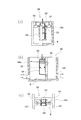
本実施形態に係る放水設備を説明する。該放水設備1は、例えば、図1〜図3に示すように、堤体2に設けられ、堤体2によって堰き止められた水の一部を貯水する貯水部3と、該貯水部3に貯水された水を堤体2より下流側へ放流する放流路4とを備える。
A water discharge facility according to the present embodiment will be described. As shown in FIGS. 1 to 3, for example, the
貯水部3は、貯水量が貯水可能量を超えた場合に、貯水された水が堤体2から越流するように構成される。具体的には、貯水部3は、貯水された水が、後述する堤体2の下流側隔壁20から越流するように構成される。
The
貯水部3は、堤体2の上部に凹部を形成して設けられる。具体的には、水の流れる方向に対して直交方向に設置された堤体2の下流側隔壁20と、該下流側隔壁20の両端部から上流側に向かって延出される(水の流れる方向とは反対方向に向かって延出される)堤体2の一対の側壁21,21と、下流側隔壁20と一対の側壁21,21とで画定される底面の開口を閉塞する堤体2の底壁22と、下流側隔壁20と一対の側壁21,21と底壁22とで画定される上流側の開口の上側部を閉塞する堤体2の上流側隔壁23と、を備える。
The
上流側隔壁23の下端部には、堤体2の上流側の水を貯水部3内へ引き込むための流入口24が設けられる。具体的には、流入口24は、上流側隔壁23の下端部と底壁22の上流側の端部との間に形成される。また、流入口24には、塵芥Xの流入を防止するネット25が取り付けられる。
An
また、上流側隔壁23の上端部には、後述する放流路4のフロート41がそれ以上上昇しないように、該フロート41の上昇を規制するプレート26が取り付けられている。
A
プレート26は、フロート41が出退可能な大きさの貫通孔260が形成される。また、プレート26の上流側端部26aは、上流側隔壁23の上端部の端面に取り付けられる。また、プレート26の下流側端部26bは、一旦、垂直方向(上側)に折り曲げられた後、先端部側が水平方向に折り曲げられる。その結果、該先端部の下面と下流側隔壁20の上端部の端面との間に隙間(越流口)Hが形成される。この隙間Hは、後述する放流本管421の放水口422aが蓋43で閉塞された状態において、取水口401に取り付けられたスクリーン402に付着した塵芥Xを下流側に放流させるためのものである。
The
放流路4は、貯水部3内に昇降可能に構成された取水体40と、貯水部3の貯水量に応じて取水体40を昇降させるフロート41と、貯水部3の水を下流側に放流するための放水口421aを有する放流管路42と、前記放水口421aを開閉可能に構成された蓋43と、を備える。
The
取水体40は、筒状で、後述する放流管路42の接続管420に対して上下動可能に内挿される。また、取水体40は、フロート41の下端に接続される接続部400と、該接続部400から所定の距離をおいて設けられた取水口401と、該取水口401に配置され、取水口401を通って取水体40の内部への塵芥Xの流入を防止するためのスクリーン402と、取水体40の上下動における下限位置を規制する第一規制体403と、取水体40の上下動における上限位置を規制する第二規制体404と、を備える。
The
取水口401は、貯水部3の内面よりも内部側へ離間して配置される。具体的には、フロート41、取水体40、放流管路42等は、下流側隔壁20と上流側隔壁23との間に配置される。
The
フロート41は、下流側隔壁20と、一対の側壁21,21と、底壁22と、上流側隔壁23とで画定される貯水部3内に配置される。また、フロート41は、半球形状で、環状のストッパ410が取り付けられる。このストッパ410は、プレート26の貫通孔260の開口周縁部に当接し、フロート41が貫通孔260から抜け出ることを防止する。
The
放流管路42は、鉛直方向に延び且つ取水体40を上下方向に案内する筒状の接続管420と、該接続管420に一端部が接続され、他端部が放水口421aを有する筒状の放流本管421と、を備える。
The
接続管420の上端開口部の周縁部には、取水体40の第二規制体404に係止する環状の係止部420aが形成される。
An
放流本管421は、一端部が垂直方向に延出されて接続管420に接続され、他端部が水平方向に延出され、貯水部3の水を下流側に放流するための放水口421aが設けられている。
One end of the discharge
蓋43は、放流本管421の放水口421aに対して水圧で開くように構成されている。具体的には、取水口401より取り込んだ水の水圧が所定圧より高い場合は、放水口422aを開放し、所定圧より低い場合は、放水口421aを閉塞するよう構成されている。また、蓋43は、本実施形態では、円板状で、放流本管421の放水口421aの開口周縁部にはパッキンPが装着され、蓋43によって放水口421aは密閉されるように構成される。
The lid | cover 43 is comprised so that it may open with a hydraulic pressure with respect to the
つぎに本実施形態に係る放水設備の使用態様について説明する。まず、図1の状態は、上流側からの水が貯水部3に流入して満水の状態であり、フロート41がプレート26の貫通孔260から突出し、貯水部3の水が取水体40、接続管420を通って放流本管421の放水口421aから放水される。
Next, a usage aspect of the water discharge facility according to the present embodiment will be described. First, the state of FIG. 1 is a state where water from the upstream side flows into the
このとき、プレート26の貫通孔260の周縁部には、フロート41のストッパ410が当接するとともに、第二規制体404が接続管420の上端開口部の係止部420aに係止する。また、取水体40、接続管420、放流本管421を通った水の水圧によって蓋43が押し開けられる。
At this time, the
この状態から、貯水部3の水が減少すると、図4に示すように、貯水部3の水が取水体(接続管420)40、放流本管421の放水口421aから放水される。
When the water in the
このとき、プレート26の貫通孔260からフロート41が退避し、取水体40の第一規制体403が接続管420の上端開口部の係止部420aに当接し、接続管420及び放流本管421を通る水の水圧によって蓋43が押し開けられる。
At this time, the
すなわち、貯水部3の水位が変化しても、貯水部3の水面から取水口401の距離は一定であり、取水口401から一定流量の水(維持流量)が下流側に放水されることになる。
That is, even if the water level of the
つぎに、図5に示すように、取水口401に塵芥Xが付着(堆積)すると、取水口401より取り込んだ水の水圧が所定圧より低くなり、放水口421aを蓋43が閉塞する。そうすると、放水口421aから放流されなくなるため、貯水部3に溜まる水が増加する。そして、貯水部3において、貯水可能量を超えると、貯水部3内の水が堤体2の下流側隔壁20を超えて下流側へ放流され(越流が起きる)、放流量が維持される。
Next, as shown in FIG. 5, when the dust X adheres (deposits) to the
ここで、越流が起こると、放流路4を介した放流による水の流れとは異なる水の流れが貯水部3に生じることになる。すなわち、取水口401に付着している塵芥Xは、放流路4を介した放流による水の流れで取水口401に付着した物である。よって、貯水部3内の水の流れが放流路4を介した放流による水の流れから越流による水の流れに変わることによって、塵芥Xは越流による水の流れにのって取水口401から除去される。そうすると、取水口401からの取水量は回復して増加するため、蓋43にかかる水圧も回復して増加する。そうすると、蓋43は放水口421aを開放するから放流路4からの放流が再開される。
Here, when overflow occurs, a water flow different from the water flow by discharge through the
具体的には、越流が起きている場合の貯水部3内の水の流れは、上流側隔壁23の下側の流入口24から下流側隔壁20の上側へ向けた斜め上方の流れとなる。この斜め上方への流れを受ける位置に取水口401は配置されている。
Specifically, the flow of water in the
すなわち、取水口401は、貯水部3の内面よりも内部側へ離間して配置されるから、前記斜め上方への流れに晒される。よって取水口401に付着した塵芥Xを効果的に除去することができる。
That is, since the
このように、本実施形態に係る放水設備によれば、取水体40の取水口401に付着した塵芥Xを容易に除去することができる。
Thus, according to the water discharge facility according to the present embodiment, the dust X attached to the
なお、本発明は、前記実施形態に限定されるものではなく、本発明の要旨を逸脱しない範囲で種々変更を加え得ることは勿論のことである。 It should be noted that the present invention is not limited to the above-described embodiment, and it is needless to say that various modifications can be made without departing from the gist of the present invention.
例えば、前記実施形態の場合、放流管路42は、貯水部3の底壁22から下方へ形成するようにしたが、これに限らず、下流側隔壁20から下流側へ形成してもよいし、側壁21から側方へ形成してもよい。
For example, in the case of the above-described embodiment, the
また、前記実施形態の場合、取水口401は貯水部3の内面から離間して配置された場合に限らず、貯水部3の内面(例えば、底壁22の面、下流側隔壁20の面、側壁21の面)に設けてもよい。
Moreover, in the case of the said embodiment, the
また、前記実施形態の場合、取水体40は、昇降式にしたが、これに限らず、固定式でもよい。固定式の場合、フロート41は不要である。
Moreover, in the case of the said embodiment, although the
また、前記実施形態の場合、放水口421aを開閉する構成としては、蓋43を自重によって開方向へ回動するように構成し、放水による所定圧以上の水圧で蓋43を開方向へ回動保持する構成にしたが、これに限らず、蓋43を自重によって閉方向へ回動するように構成し、該蓋43を開の状態で保持する保持機構と、放水の水圧を検出する水圧センサと、検出した水圧が所定圧より低い場合に、保持機構の保持を解除する制御部とを備える構成とすることもできる。
Moreover, in the case of the said embodiment, as a structure which opens and closes the
また、前記実施形態の場合、放流本管421の蓋43を水圧のみで開閉するようにしたが、蓋43を閉塞する方向に付勢する弾性部材によって開閉するようにしてもよいし、スライド式であってもよい。
In the above embodiment, the
また、前記実施形態の場合、取水体40は昇降可能に構成したが、上下の軸線周りに回転可能に構成することもできる。この場合、越流時の斜め上方への水流によって回転するから、効果的に除塵できる。
Moreover, in the case of the said embodiment, although the
また、前記実施形態の場合、堤体2の流入口24は、上流側隔壁23の下側に設けたが、これに限らず、上端部や中間部に設けてもよい。また、中間部と下端部の二箇所に設けてもよい。
Moreover, in the case of the said embodiment, although the
また、前記実施形態の場合、貯水部3は、堤体2の上部に凹部を形成して設けたが、これに限らず、堤体2の上流側側面を利用して貯水部を設けてもよい。例えば、上流側側面から上流側に突設された一対の側壁と、該一対の側壁を連結する壁とで、貯水部を構成する。この場合、上部及び底部を開放し、底部開口を流入口とし、該流入口の近傍に取水口を配置し、流入口から上部開口への水流によって塵芥を除去するようにする。
Moreover, in the case of the said embodiment, although the
また、前記実施形態の場合、ダムの堤体を例にとって説明したが、堤防の堤体であってもよい。 In the case of the above embodiment, the dam body is described as an example, but a dam body may be used.
なお、前記実施形態において、「所定の水圧」とは、放流本管421の放水口421aからの放流量が、予め定められた量であるときの放水口421aの付近での水圧を言う。
In the embodiment, the “predetermined water pressure” refers to a water pressure in the vicinity of the
1…放水設備、2…堤体、20…下流側隔壁、21…側壁、22…底壁、23…上流側隔壁、24…流入口、25…ネット、26…プレート、260…貫通孔、3…貯水部、4…放流路、40…取水体、400…接続部、401…取水口、402…スクリーン、403…第一規制体、404…第二規制体、41…フロート、410…ストッパ、42…放流管路、420…接続管、420a…係止部、421…放流本管、421a…放水口、43…蓋、P…パッキン、H…隙間、X…塵芥
DESCRIPTION OF
Claims (4)
貯水部は、貯水量が貯水可能量を超えた場合に、貯水が堤体から越流するように構成され、
放流路は、貯水部の水を取り込むための取水口と、取り込んだ水を堤体の下流側へ放流する放水口と、
放水口を開閉可能に構成された蓋と、を備え、
蓋は、取水口より取り込んだ水の水圧が所定圧より高い場合には、放水口を開放し、所定圧より低い場合には、放水口を閉塞するよう構成されていることを特徴とする放水設備。 A water storage part that is provided in the bank body and stores a part of the water blocked by the bank body, and a discharge channel that discharges the water stored in the water storage part downstream from the bank body,
The water reservoir is configured so that when the amount of stored water exceeds the amount that can be stored, the stored water will overflow the dam body,
The discharge channel includes a water intake port for taking in water from the water reservoir, a water discharge port for discharging the taken water to the downstream side of the dam body,
A lid configured to be able to open and close the water outlet,
The lid is configured to open the water outlet when the water pressure taken from the water inlet is higher than a predetermined pressure, and to close the water outlet when lower than the predetermined pressure. Facility.
上流側隔壁には、その上端部にフロートがそれ以上上昇しないように、該フロートの上昇を規制するプレートが取り付けられていることを特徴とする請求項2又は3に記載の放水設備。 The discharge channel includes a water intake body that has a water intake and is configured to be movable up and down in the water storage section, and a float that raises and lowers the water intake body according to the amount of water stored in the water storage section.
The water discharge facility according to claim 2 or 3, wherein a plate that regulates the rise of the float is attached to the upper end partition so that the float does not rise any further.
Priority Applications (1)
| Application Number | Priority Date | Filing Date | Title |
|---|---|---|---|
| JP2016017433A JP6731177B2 (en) | 2016-02-01 | 2016-02-01 | Water discharge equipment |
Applications Claiming Priority (1)
| Application Number | Priority Date | Filing Date | Title |
|---|---|---|---|
| JP2016017433A JP6731177B2 (en) | 2016-02-01 | 2016-02-01 | Water discharge equipment |
Publications (2)
| Publication Number | Publication Date |
|---|---|
| JP2017137633A true JP2017137633A (en) | 2017-08-10 |
| JP6731177B2 JP6731177B2 (en) | 2020-07-29 |
Family
ID=59566742
Family Applications (1)
| Application Number | Title | Priority Date | Filing Date |
|---|---|---|---|
| JP2016017433A Active JP6731177B2 (en) | 2016-02-01 | 2016-02-01 | Water discharge equipment |
Country Status (1)
| Country | Link |
|---|---|
| JP (1) | JP6731177B2 (en) |
Cited By (2)
| Publication number | Priority date | Publication date | Assignee | Title |
|---|---|---|---|---|
| CN106702972A (en) * | 2017-02-07 | 2017-05-24 | 芜湖市银鸿液压件有限公司 | Hydraulic dam anti-freezing device and use method thereof |
| CN107460854A (en) * | 2017-09-25 | 2017-12-12 | 芜湖市银鸿液压件有限公司 | A kind of road junction lock |
-
2016
- 2016-02-01 JP JP2016017433A patent/JP6731177B2/en active Active
Cited By (2)
| Publication number | Priority date | Publication date | Assignee | Title |
|---|---|---|---|---|
| CN106702972A (en) * | 2017-02-07 | 2017-05-24 | 芜湖市银鸿液压件有限公司 | Hydraulic dam anti-freezing device and use method thereof |
| CN107460854A (en) * | 2017-09-25 | 2017-12-12 | 芜湖市银鸿液压件有限公司 | A kind of road junction lock |
Also Published As
| Publication number | Publication date |
|---|---|
| JP6731177B2 (en) | 2020-07-29 |
Similar Documents
| Publication | Publication Date | Title |
|---|---|---|
| JP6682065B2 (en) | Drainage pipe | |
| JP2017137633A (en) | Water discharge facility | |
| KR102289385B1 (en) | Condensate discharge device | |
| JP4772489B2 (en) | Reactor building | |
| JP3831280B2 (en) | Seal pit for drainage | |
| JP3202897U (en) | Reservoir level adjustment 枡 | |
| JP6564987B2 (en) | Drain trap | |
| JP6333526B2 (en) | Piping unit for temporary toilet installation | |
| JP2009299308A (en) | Back flow preventing structure and drainage facility | |
| KR101400925B1 (en) | Apparatus for discharging sea water for reduce bubble occurrence | |
| KR20150002216U (en) | A backflow preventing scupper | |
| JP5227347B2 (en) | Wave power generator | |
| JP5705797B2 (en) | Water intake restriction device | |
| JP6424040B2 (en) | Float valve | |
| JP6779065B2 (en) | Air valve | |
| JP2004084319A (en) | Lifting gate type water intake device | |
| JP7276735B2 (en) | Drainage device | |
| JP6804223B2 (en) | Backflow prevention device | |
| JP7227638B2 (en) | catch basin | |
| JP2019183861A (en) | Valve opening/closing method in drain water discharge device and drain water discharge device | |
| JP7336164B2 (en) | Water volume adjustment block for catch basin | |
| JP6040354B2 (en) | Drainage equipment | |
| JP2014173249A (en) | Stand-and-lie gate type breakwater | |
| CN205839939U (en) | A kind of Novel drain | |
| US785680A (en) | Flush-tank. |
Legal Events
| Date | Code | Title | Description |
|---|---|---|---|
| A621 | Written request for application examination |
Free format text: JAPANESE INTERMEDIATE CODE: A621 Effective date: 20190124 |
|
| A977 | Report on retrieval |
Free format text: JAPANESE INTERMEDIATE CODE: A971007 Effective date: 20191107 |
|
| A131 | Notification of reasons for refusal |
Free format text: JAPANESE INTERMEDIATE CODE: A131 Effective date: 20191115 |
|
| A521 | Request for written amendment filed |
Free format text: JAPANESE INTERMEDIATE CODE: A523 Effective date: 20200107 |
|
| TRDD | Decision of grant or rejection written | ||
| A01 | Written decision to grant a patent or to grant a registration (utility model) |
Free format text: JAPANESE INTERMEDIATE CODE: A01 Effective date: 20200605 |
|
| A61 | First payment of annual fees (during grant procedure) |
Free format text: JAPANESE INTERMEDIATE CODE: A61 Effective date: 20200618 |
|
| R150 | Certificate of patent or registration of utility model |
Ref document number: 6731177 Country of ref document: JP Free format text: JAPANESE INTERMEDIATE CODE: R150 |