JP2017136889A - Steering device - Google Patents
Steering device Download PDFInfo
- Publication number
- JP2017136889A JP2017136889A JP2016017256A JP2016017256A JP2017136889A JP 2017136889 A JP2017136889 A JP 2017136889A JP 2016017256 A JP2016017256 A JP 2016017256A JP 2016017256 A JP2016017256 A JP 2016017256A JP 2017136889 A JP2017136889 A JP 2017136889A
- Authority
- JP
- Japan
- Prior art keywords
- yoke
- shaft
- angle
- steering
- intermediate shaft
- Prior art date
- Legal status (The legal status is an assumption and is not a legal conclusion. Google has not performed a legal analysis and makes no representation as to the accuracy of the status listed.)
- Pending
Links
- 238000003780 insertion Methods 0.000 claims abstract description 28
- 230000037431 insertion Effects 0.000 claims abstract description 28
- 230000007935 neutral effect Effects 0.000 claims description 22
- 238000003466 welding Methods 0.000 description 11
- 238000010586 diagram Methods 0.000 description 4
- 230000002093 peripheral effect Effects 0.000 description 2
- 230000007423 decrease Effects 0.000 description 1
- 230000000694 effects Effects 0.000 description 1
- 238000002955 isolation Methods 0.000 description 1
- 238000000034 method Methods 0.000 description 1
- 238000012986 modification Methods 0.000 description 1
- 230000004048 modification Effects 0.000 description 1
- 239000007787 solid Substances 0.000 description 1
Images


Classifications
-
- F—MECHANICAL ENGINEERING; LIGHTING; HEATING; WEAPONS; BLASTING
- F16—ENGINEERING ELEMENTS AND UNITS; GENERAL MEASURES FOR PRODUCING AND MAINTAINING EFFECTIVE FUNCTIONING OF MACHINES OR INSTALLATIONS; THERMAL INSULATION IN GENERAL
- F16D—COUPLINGS FOR TRANSMITTING ROTATION; CLUTCHES; BRAKES
- F16D3/00—Yielding couplings, i.e. with means permitting movement between the connected parts during the drive
- F16D3/16—Universal joints in which flexibility is produced by means of pivots or sliding or rolling connecting parts
- F16D3/26—Hooke's joints or other joints with an equivalent intermediate member to which each coupling part is pivotally or slidably connected
- F16D3/38—Hooke's joints or other joints with an equivalent intermediate member to which each coupling part is pivotally or slidably connected with a single intermediate member with trunnions or bearings arranged on two axes perpendicular to one another
- F16D3/382—Hooke's joints or other joints with an equivalent intermediate member to which each coupling part is pivotally or slidably connected with a single intermediate member with trunnions or bearings arranged on two axes perpendicular to one another constructional details of other than the intermediate member
- F16D3/387—Fork construction; Mounting of fork on shaft; Adapting shaft for mounting of fork
-
- B—PERFORMING OPERATIONS; TRANSPORTING
- B62—LAND VEHICLES FOR TRAVELLING OTHERWISE THAN ON RAILS
- B62D—MOTOR VEHICLES; TRAILERS
- B62D1/00—Steering controls, i.e. means for initiating a change of direction of the vehicle
- B62D1/02—Steering controls, i.e. means for initiating a change of direction of the vehicle vehicle-mounted
- B62D1/16—Steering columns
- B62D1/20—Connecting steering column to steering gear
-
- F—MECHANICAL ENGINEERING; LIGHTING; HEATING; WEAPONS; BLASTING
- F16—ENGINEERING ELEMENTS AND UNITS; GENERAL MEASURES FOR PRODUCING AND MAINTAINING EFFECTIVE FUNCTIONING OF MACHINES OR INSTALLATIONS; THERMAL INSULATION IN GENERAL
- F16D—COUPLINGS FOR TRANSMITTING ROTATION; CLUTCHES; BRAKES
- F16D1/00—Couplings for rigidly connecting two coaxial shafts or other movable machine elements
- F16D1/06—Couplings for rigidly connecting two coaxial shafts or other movable machine elements for attachment of a member on a shaft or on a shaft-end
- F16D1/08—Couplings for rigidly connecting two coaxial shafts or other movable machine elements for attachment of a member on a shaft or on a shaft-end with clamping hub; with hub and longitudinal key
- F16D1/0847—Couplings for rigidly connecting two coaxial shafts or other movable machine elements for attachment of a member on a shaft or on a shaft-end with clamping hub; with hub and longitudinal key with radial clamping due to a radial screw
-
- F—MECHANICAL ENGINEERING; LIGHTING; HEATING; WEAPONS; BLASTING
- F16—ENGINEERING ELEMENTS AND UNITS; GENERAL MEASURES FOR PRODUCING AND MAINTAINING EFFECTIVE FUNCTIONING OF MACHINES OR INSTALLATIONS; THERMAL INSULATION IN GENERAL
- F16D—COUPLINGS FOR TRANSMITTING ROTATION; CLUTCHES; BRAKES
- F16D1/00—Couplings for rigidly connecting two coaxial shafts or other movable machine elements
- F16D1/06—Couplings for rigidly connecting two coaxial shafts or other movable machine elements for attachment of a member on a shaft or on a shaft-end
- F16D1/08—Couplings for rigidly connecting two coaxial shafts or other movable machine elements for attachment of a member on a shaft or on a shaft-end with clamping hub; with hub and longitudinal key
- F16D1/0852—Couplings for rigidly connecting two coaxial shafts or other movable machine elements for attachment of a member on a shaft or on a shaft-end with clamping hub; with hub and longitudinal key with radial clamping between the mating surfaces of the hub and shaft
- F16D1/0864—Couplings for rigidly connecting two coaxial shafts or other movable machine elements for attachment of a member on a shaft or on a shaft-end with clamping hub; with hub and longitudinal key with radial clamping between the mating surfaces of the hub and shaft due to tangential loading of the hub, e.g. a split hub
-
- F—MECHANICAL ENGINEERING; LIGHTING; HEATING; WEAPONS; BLASTING
- F16—ENGINEERING ELEMENTS AND UNITS; GENERAL MEASURES FOR PRODUCING AND MAINTAINING EFFECTIVE FUNCTIONING OF MACHINES OR INSTALLATIONS; THERMAL INSULATION IN GENERAL
- F16C—SHAFTS; FLEXIBLE SHAFTS; ELEMENTS OR CRANKSHAFT MECHANISMS; ROTARY BODIES OTHER THAN GEARING ELEMENTS; BEARINGS
- F16C3/00—Shafts; Axles; Cranks; Eccentrics
- F16C3/02—Shafts; Axles
- F16C3/03—Shafts; Axles telescopic
-
- F—MECHANICAL ENGINEERING; LIGHTING; HEATING; WEAPONS; BLASTING
- F16—ENGINEERING ELEMENTS AND UNITS; GENERAL MEASURES FOR PRODUCING AND MAINTAINING EFFECTIVE FUNCTIONING OF MACHINES OR INSTALLATIONS; THERMAL INSULATION IN GENERAL
- F16D—COUPLINGS FOR TRANSMITTING ROTATION; CLUTCHES; BRAKES
- F16D1/00—Couplings for rigidly connecting two coaxial shafts or other movable machine elements
- F16D1/06—Couplings for rigidly connecting two coaxial shafts or other movable machine elements for attachment of a member on a shaft or on a shaft-end
- F16D1/08—Couplings for rigidly connecting two coaxial shafts or other movable machine elements for attachment of a member on a shaft or on a shaft-end with clamping hub; with hub and longitudinal key
- F16D1/0894—Couplings for rigidly connecting two coaxial shafts or other movable machine elements for attachment of a member on a shaft or on a shaft-end with clamping hub; with hub and longitudinal key with other than axial keys, e.g. diametral pins, cotter pins and no other radial clamping
-
- F—MECHANICAL ENGINEERING; LIGHTING; HEATING; WEAPONS; BLASTING
- F16—ENGINEERING ELEMENTS AND UNITS; GENERAL MEASURES FOR PRODUCING AND MAINTAINING EFFECTIVE FUNCTIONING OF MACHINES OR INSTALLATIONS; THERMAL INSULATION IN GENERAL
- F16D—COUPLINGS FOR TRANSMITTING ROTATION; CLUTCHES; BRAKES
- F16D1/00—Couplings for rigidly connecting two coaxial shafts or other movable machine elements
- F16D1/10—Quick-acting couplings in which the parts are connected by simply bringing them together axially
- F16D1/108—Quick-acting couplings in which the parts are connected by simply bringing them together axially having retaining means rotating with the coupling and acting by interengaging parts, i.e. positive coupling
- F16D1/116—Quick-acting couplings in which the parts are connected by simply bringing them together axially having retaining means rotating with the coupling and acting by interengaging parts, i.e. positive coupling the interengaging parts including a continuous or interrupted circumferential groove in the surface of one of the coupling parts
-
- F—MECHANICAL ENGINEERING; LIGHTING; HEATING; WEAPONS; BLASTING
- F16—ENGINEERING ELEMENTS AND UNITS; GENERAL MEASURES FOR PRODUCING AND MAINTAINING EFFECTIVE FUNCTIONING OF MACHINES OR INSTALLATIONS; THERMAL INSULATION IN GENERAL
- F16D—COUPLINGS FOR TRANSMITTING ROTATION; CLUTCHES; BRAKES
- F16D1/00—Couplings for rigidly connecting two coaxial shafts or other movable machine elements
- F16D1/10—Quick-acting couplings in which the parts are connected by simply bringing them together axially
- F16D2001/103—Quick-acting couplings in which the parts are connected by simply bringing them together axially the torque is transmitted via splined connections
-
- F—MECHANICAL ENGINEERING; LIGHTING; HEATING; WEAPONS; BLASTING
- F16—ENGINEERING ELEMENTS AND UNITS; GENERAL MEASURES FOR PRODUCING AND MAINTAINING EFFECTIVE FUNCTIONING OF MACHINES OR INSTALLATIONS; THERMAL INSULATION IN GENERAL
- F16D—COUPLINGS FOR TRANSMITTING ROTATION; CLUTCHES; BRAKES
- F16D2250/00—Manufacturing; Assembly
- F16D2250/0061—Joining
- F16D2250/0076—Welding, brazing
Landscapes
- Engineering & Computer Science (AREA)
- General Engineering & Computer Science (AREA)
- Mechanical Engineering (AREA)
- Chemical & Material Sciences (AREA)
- Combustion & Propulsion (AREA)
- Transportation (AREA)
- Steering Controls (AREA)
- Vehicle Body Suspensions (AREA)
Abstract
Description
この発明は、ステアリング装置に関する。 The present invention relates to a steering device.
ステアリング装置には、一般に、ステアリングホイールが装着可能なステアリングシャフトと、ステアリングギアのピニオン軸とを連結する中間シャフトが備えられている。中間シャフトおよびステアリングシャフトの間と、中間シャフトおよびピニオン軸の間とには、それぞれ、自在継手が介在されている(例えば下記特許文献1参照)。
In general, a steering device includes an intermediate shaft that connects a steering shaft to which a steering wheel can be mounted and a pinion shaft of a steering gear. Universal joints are interposed between the intermediate shaft and the steering shaft and between the intermediate shaft and the pinion shaft, respectively (see, for example,
特許文献1に開示されているように、中間シャフトとピニオン軸との間の自在継手は、ボルトによってピニオン軸と連結される。ステアリング装置を車体に組み付ける際に、このボルトを取り付ける方向が、作業のし易い方向でない場合、自在継手をステアリング装置に組み付ける作業の効率が低下する虞がある。
この発明は、かかる背景のもとでなされたものであり、車体に対する組み付け性が向上されたステアリング装置を提供することを目的とする。
As disclosed in
The present invention has been made under such a background, and an object of the present invention is to provide a steering device with improved assembling performance with respect to a vehicle body.
請求項1に記載の発明は、操舵部材(2)の回転力が一端側から伝達されるインターミディエイトシャフト(4)と、前記インターミディエイトシャフトの一端(4A)に連結された第1自在継手(9;9P)と、前記インターミディエイトシャフトの他端(4B)に連結された第2自在継手(10)と、を含み、前記第1自在継手は、前記インターミディエイトシャフトに連結された第1ヨーク(20;20P)と、前記第1ヨークと対をなす第2ヨーク(30)とを備え、前記第2自在継手は、前記インターミディエイトシャフトに連結された第3ヨーク(50)と、前記第3ヨークと対をなす第4ヨーク(60)と、前記第4ヨークに連結され前記第4ヨークに軸(5)を取り付けるための軸取付部(70)とを備え、前記軸取付部には、軸(5)を締め付けるためのボルト挿通孔(73)が形成されており、前記インターミディエイトシャフトと前記第2ヨークに連結される軸(3)とがなす角度(β)がθ1とされ、軸方向回りの回転方向(S)における前記第1ヨークの軸回り角度(α)がω1とされ、かつ、前記インターミディエイトシャフトと前記第4ヨークに連結される軸(5)とがなす角度(γ)がθ2とされた状態において、前記軸取付部の前記ボルト挿通孔の前記回転方向における軸回り角度(φ)が予め定められた角度ω2になるように、前記回転方向における前記第4ヨークと前記軸取付部との接合角度(ε)が調整されている、ステアリング装置(1;1P)である。 According to the first aspect of the present invention, there is provided an intermediate shaft (4) through which the rotational force of the steering member (2) is transmitted from one end side, and a first universal joint connected to one end (4A) of the intermediate shaft ( 9; 9P) and a second universal joint (10) connected to the other end (4B) of the intermediate shaft, wherein the first universal joint is a first yoke connected to the intermediate shaft. (20; 20P) and a second yoke (30) paired with the first yoke, and the second universal joint includes a third yoke (50) connected to the intermediate shaft, and the second yoke (30). A fourth yoke (60) paired with three yokes, and a shaft attachment portion (70) connected to the fourth yoke and attaching a shaft (5) to the fourth yoke. A bolt insertion hole (73) for tightening the shaft (5) is formed, and an angle (β) formed by the intermediate shaft and the shaft (3) connected to the second yoke is θ1, An axial angle (α) of the first yoke in the rotational direction (S) around the axial direction is ω1, and an angle formed between the intermediate shaft and the axis (5) connected to the fourth yoke ( In the state where γ) is set to θ2, the fourth yoke in the rotation direction so that the angle around the axis (φ) in the rotation direction of the bolt insertion hole of the shaft mounting portion becomes a predetermined angle ω2. And a steering device (1; 1P) in which a joint angle (ε) between the shaft mounting portion and the shaft mounting portion is adjusted.
請求項2に記載の発明は、前記第1ヨークの軸回り角度がω1とされた状態では、前記操舵部材が操舵中立位置にあるときに前記第1ヨークの一対の腕部(21;21P)が上下または左右に配置されることを特徴とする、請求項1に記載のステアリング装置である。
請求項3に記載の発明は、前記第4ヨークと前記軸取付部とは、セレーション嵌合されていることを特徴とする、請求項1または2に記載のステアリング装置である。
According to a second aspect of the present invention, in the state where the angle around the axis of the first yoke is ω1, when the steering member is in the steering neutral position, the pair of arms (21; 21P) of the first yoke The steering apparatus according to
The invention according to claim 3 is the steering apparatus according to
請求項4に記載の発明は、前記第4ヨークと前記軸取付部とは、接合されていることを特徴とする、請求項1〜3の何れか一項に記載のステアリング装置である。
なお、上記において、括弧内の数字等は、後述する実施形態における対応構成要素の参照符号を表すものであるが、これらの参照符号により特許請求の範囲を限定する趣旨ではない。
The invention according to
In addition, in the above, the numbers in parentheses represent reference numerals of corresponding components in the embodiments described later, but the scope of the claims is not limited by these reference numerals.
請求項1に記載の発明によれば、インターミディエイトシャフトと第2ヨークに連結される軸とがなす角度がθ1とされ、軸方向回りの回転方向における第1ヨークの軸回り角度がω1とされ、かつ、インターミディエイトシャフトと第4ヨークに連結される軸とがなす角度がθ2とされた状態において、軸取付部のボルト挿通孔の回転方向における軸回り角度が、ボルト挿通孔へボルトを挿通する作業をし易い角度(予め定められた角度)ω2になるように、第4ヨークと軸取付部との接合角度を調整することができる。そのため、車体に対するステアリング装置の組み付け性を向上させることができる。 According to the first aspect of the present invention, the angle formed by the intermediate shaft and the shaft connected to the second yoke is θ1, and the axis angle of the first yoke in the rotational direction about the axis direction is ω1. In addition, when the angle between the intermediate shaft and the shaft connected to the fourth yoke is θ2, the angle around the axis in the rotation direction of the bolt insertion hole of the shaft mounting portion inserts the bolt into the bolt insertion hole. It is possible to adjust the joint angle between the fourth yoke and the shaft mounting portion so that the angle (predetermined angle) ω2 at which the work is easily performed is obtained. Therefore, it is possible to improve the assembling property of the steering device with respect to the vehicle body.
請求項2に記載の発明によれば、第1ヨークの軸回り角度がω1とされた状態では、操舵部材が操舵中立位置にあるときに第1ヨークの一対の腕部が上下または左右に配置されるので、インターミディエイトシャフトのねじり剛性は、車両の運転者が操舵部材を操舵中立位置から左右のどちらに操舵しても同じように変化する。そのため、車両の運転者は、操舵部材を操舵中立位置から左右のどちらに操舵しても同じ操舵感を受ける。したがって、良好な操舵感を損なうことなく車体に対するステアリング装置の組み付け性を向上させることができる。 According to the second aspect of the present invention, in the state in which the first yoke has a shaft rotation angle of ω1, when the steering member is in the steering neutral position, the pair of arms of the first yoke are arranged vertically or horizontally. Therefore, the torsional rigidity of the intermediate shaft changes in the same manner regardless of whether the driver of the vehicle steers the steering member from the steering neutral position to the left or right. Therefore, the driver of the vehicle receives the same steering feeling regardless of whether the steering member is steered to the left or right from the steering neutral position. Therefore, it is possible to improve the assembling property of the steering device with respect to the vehicle body without impairing a good steering feeling.
請求項3に記載の発明によれば、第4ヨークと軸取付部とはセレーション嵌合されているので、第4ヨークと軸取付部との接合角度を容易に調整することができる。
請求項4に記載の発明によれば、第4ヨークと軸取付部とは、接合されているので、第4ヨークと軸取付部とを強固に固定することができる。
According to the third aspect of the invention, since the fourth yoke and the shaft mounting portion are serrated and fitted, the joint angle between the fourth yoke and the shaft mounting portion can be easily adjusted.
According to the fourth aspect of the invention, since the fourth yoke and the shaft mounting portion are joined, the fourth yoke and the shaft mounting portion can be firmly fixed.
以下では、本発明の実施形態を、添付図面を参照して詳細に説明する。
<第1実施形態>
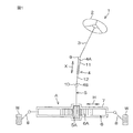
図1は、本発明の第1実施形態に係るステアリング装置1の模式図である。ステアリング装置1は、ステアリングホイール等の操舵部材2が一端に連結された操舵軸3を介して操舵部材2の回転力が一端4A側から伝達されるインターミディエイトシャフト4を含む。インターミディエイトシャフト4は、当該回転力を、転舵輪Wを転舵する転舵機構Aに伝達する。
Hereinafter, embodiments of the present invention will be described in detail with reference to the accompanying drawings.
<First Embodiment>
FIG. 1 is a schematic diagram of a
ステアリング装置1は、インターミディエイトシャフト4の一端4A(操舵部材2側の端)と操舵軸3とに連結された第1自在継手9と、インターミディエイトシャフト4の他端4B(操舵部材2側とは反対側の端)と転舵機構Aのピニオン軸5とに連結された第2自在継手10とをさらに含む。
インターミディエイトシャフト4は、インターミディエイトシャフト4の軸方向Xに伸縮可能であり、例えばスプライン嵌合によって相対移動可能かつ一体回転可能に嵌合された第1軸11および第2軸12を備える。第1軸11には、第1自在継手9が連結されており、第2軸12には、第2自在継手10が連結されている。
The
The
ピニオン軸5には、ピニオン軸5とともに転舵機構Aを構成するラック軸6に形成されたラック6Aと噛み合うピニオン5Aが形成されている。ラック軸6は、車両の左右に水平に延びる左右方向Hに長手の棒状であり、ラックハウジング7に挿通されている。左右方向Hは、車幅方向でもある。左右方向Hにおけるラック軸6の両端のそれぞれには、タイロッド8が連結されている。タイロッド8は、ナックルアーム(図示せず)を介して転舵輪Wに連結されている。
The
図2は、インターミディエイトシャフト4の周辺を示した側面図である。図2では、紙面に対して垂直な方向に左右方向Hを向けて各部材を図示している。
以下では、操舵軸3の中心軸線C1回りの回転方向、インターミディエイトシャフト4の中心軸線C2回りの回転方向およびピニオン軸5の中心軸線C3回りの回転方向を回転方向Sという。回転方向Sは、操舵軸3、インターミディエイトシャフト4およびピニオン軸5の軸方向回りの方向である。
FIG. 2 is a side view showing the periphery of the
Hereinafter, the rotational direction around the central axis C1 of the steering shaft 3, the rotational direction around the central axis C2 of the
図2を参照して、第1自在継手9は、インターミディエイトシャフト4に連結された第1ヨーク20と、第1ヨーク20と対をなす第2ヨーク30と、第1ヨーク20と第2ヨーク30とを相対変位自在に連結する十字軸40とを備える。
第1ヨーク20は、インターミディエイトシャフト4の一端4Aに溶接等により固定されたフランジ部22と、一端4Aから軸方向Xに延び、中心軸線C2を挟んで互いに対向する一対の第1腕部21とを一体に備える。
Referring to FIG. 2, the first universal joint 9 includes a
The
第2ヨーク30は、操舵軸3が挿通された筒状部31と、筒状部31から延設され筒状部31を介して操舵軸3を締め付けるための一対の締付板32とを備える。また、第2ヨーク30は、筒状部31から筒状部31の軸方向Yに延び、回転方向Sにおける一対の第1腕部21の位置から回転方向Sに沿って90°ずれた位置で中心軸線C1を挟んで互いに対向する一対の第2腕部34をさらに備える。筒状部31と一対の締付板32と一対の第2腕部34とは、一体に形成されている。
The
各締付板32には、操舵軸3を締め付けるための締付ボルト36が挿通されている。締付ボルト36によって一対の締付板32が締め付けられ、これにより、操舵軸3が筒状部31内で締め付けられている。
第2自在継手10は、インターミディエイトシャフト4に連結された第3ヨーク50と、第3ヨーク50と対をなす第4ヨーク60と、第4ヨーク60に接合され第4ヨーク60にピニオン軸5を取り付けるための軸取付部70と、第3ヨーク50と第4ヨーク60とを相対変位自在に連結する十字軸80とを備える。第4ヨーク60と軸取付部70とは、セレーション嵌合されており、溶接によって接合されている。
A
The second
第3ヨーク50は、インターミディエイトシャフト4の他端4Bに溶接等により固定されたフランジ部52と、フランジ部52から軸方向Xに延び、中心軸線C2を挟んで互いに対向する一対の第3腕部51とを一体に備える。
第4ヨーク60は、軸取付部70に接合されたフランジ部62と、中心軸C3が延びる方向である軸方向Zにフランジ部62から延び、回転方向Sにおいて一対の第3腕部51の位置に対して90°ずれた位置で互いに対向する一対の第4腕部63とを備える。
The
The
左右方向Hから見た状態でインターミディエイトシャフト4と操舵軸3とがなす角度を角度βとする。角度βは、操舵軸3とインターミディエイトシャフト4とが同軸上に配置され、かつ、操舵軸3とインターミディエイトシャフト4とが軸方向Xに隣接して配置された状態で0°となる角度である。
また、左右方向Hから見た状態でインターミディエイトシャフト4とピニオン軸5とがなす角度を角度γとする。角度γは、インターミディエイトシャフト4とピニオン軸5とが同軸上に配置され、かつ、インターミディエイトシャフト4とピニオン軸5とが軸方向Xに隣接して配置された状態で0°となる角度である。
An angle formed between the
In addition, an angle formed between the
このようなステアリング装置1を車体に組み付ける際には、角度βを仕様等により予め定められた角度θ1とし、角度γを仕様等により予め定められたθ2として、かつ、第1自在継手9および第2自在継手10を回転方向Sにおいて所定の位置に配置した状態で、ピニオン軸5を第2自在継手10の軸取付部70に挿入し、締付ボルト74でピニオン軸5を軸取付部70に取り付けるという作業が行われる。
When assembling such a
そこで、以下では、第2自在継手10とピニオン軸5との連結構造と、回転方向Sにおける第1自在継手9および第2自在継手10の位置とについて詳しく説明する。
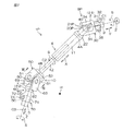
図3は、第2自在継手10の第4ヨーク60および軸取付部70の周辺の分解斜視図である。
図3を参照して、軸取付部70は、ピニオン軸5等の軸に外嵌された筒状部71と、筒状部71から延設され筒状部71を介してピニオン軸5等の軸を締め付けるための一対の締付板72とを単一の部材で一体に備える。
Therefore, in the following, the connection structure between the second
FIG. 3 is an exploded perspective view of the periphery of the
Referring to FIG. 3, the
筒状部71には、一対の締付板72の間で筒状部71の軸方向Zに沿って延びるスリット71Aが形成されている。筒状部71の内周には、ピニオン軸5の端部に形成された雄セレーション5Bとセレーション嵌合する雌セレーション71Bが形成されている。
各締付板72には、ピニオン軸5等の軸を締め付けるためのボルト挿通孔73が形成されている。ボルト挿通孔73には、締付ボルト74が挿通されている。締付ボルト74は、ピニオン軸5の周溝5Cに嵌められている(図2も参照)。締付ボルト74によって、筒状部71からのピニオン軸5の抜け止めが達成されている。締付ボルト74によって一対の締付板72が締め付けられ、これにより、ピニオン軸5が筒状部71内で締め付けられている。
The
Each
筒状部71は、フランジ部62とセレーション嵌合している。筒状部71の外周面において一対の締付板72よりもフランジ部62側の部分には、雄セレーション71Cが形成されている。フランジ部62には、筒状部71が挿通される挿通孔62Aが形成されており、挿通孔62Aの内周面には、雄セレーション71Cとセレーション嵌合する雌セレーション62Bが形成されている。
The
第4ヨーク60と軸取付部70とは、溶接による接合に限られず、かしめまたは摩擦圧接によって接合されていてもよい。かしめは、第4ヨーク60と軸取付部70とをセレーション嵌合させた状態で、第4ヨーク60のフランジ部62または軸取付部70の筒状部71を塑性変形させることによって、フランジ部62と筒状部71とを結合させることで行われる。
The
また、筒状部71とフランジ部62とのセレーション嵌合の長さを調整することで、軸方向における第4ヨーク60および軸取付部70の長さの和(ヨーク長)を調整することができる。第4ヨーク60と軸取付部70とは、ヨーク長を調整した状態で溶接、かしめまたは摩擦圧接によって接合されていてもよい。
図4は、図2のIV−IV線に沿った断面の模式図である。図4では、説明の便宜上、十字軸80の図示を省略している。また、図4では、説明の便宜上、第1ヨーク20の一対の第1腕部21を二点鎖線で図示している。操舵部材2側とは反対側から見て、回転方向Sの時計回り方向をS1方向とし、回転方向Sの反時計回り方向をS2方向とする。以下では、中心軸線C2と交差し水平(左右方向H)に延びる仮想の直線を直線L0とする。
Further, by adjusting the length of serration fitting between the
FIG. 4 is a schematic view of a cross section taken along line IV-IV in FIG. In FIG. 4, illustration of the
中心軸線C2と交差し、一対の第1腕部21が互いに対向する方向に延びる仮想の直線を直線L1とする。直線L1は、直線L0からS1方向に軸回り角度αだけずれている。軸回り角度αは、360°よりも小さい角度で表現される(0°≦α<360°)。
軸回り角度αは、仕様等により予め定められた角度ω1となるように設定されている。本実施形態では、角度ω1は、操舵部材2が操舵中立位置に位置する状態で軸回り角度αが90°または270°になるように設定された角度である。操舵中立位置とは、車両が直進するときの回転方向Sにおける操舵部材2の位置である。一対の第1腕部21は、操舵部材2が操舵中立位置に位置する状態で、上下(左右方向Hに対する直交方向)に並んで配置されている。この状態で、直線L1と直線L0とが直交する。
A virtual straight line that intersects the central axis C2 and extends in a direction in which the pair of
The axis rotation angle α is set to be a predetermined angle ω1 according to specifications and the like. In the present embodiment, the angle ω1 is an angle that is set so that the angle α around the axis is 90 ° or 270 ° in a state where the steering
中心軸線C2と交差し一対の第3腕部51が互いに対向する方向に延びる仮想の直線を直線L3とする。直線L3は、直線L1に対してS1方向に位相角δだけずれた位置である(0°≦δ<360°)。
位相角δは、インターミディエイトシャフト4と操舵軸3とがなす角度βが仕様等によって予め定められた角度θ1とされ、インターミディエイトシャフト4とピニオン軸5とがなす角度γが仕様等によって予め定められたθ2とされた状態で、操舵軸3からの回転力をピニオン軸5に効率良く伝達できる角度θ3に設定される。
A virtual straight line that intersects the central axis C2 and extends in a direction in which the pair of
The phase angle δ is set such that the angle β formed by the
図5は、図2の矢印Vから見た第2自在継手10の周辺の模式図である。図5では、説明の便宜上、ピニオン軸5および第3ヨーク50の図示を省略している。また、図5では、説明の便宜上、一対の第3腕部51が互いに対向する方向に延びる前述の直線L3を図示している。
図5を参照して、中心軸線C3と交差し一対の第4腕部63が互いに対向する方向に延びる仮想の直線を直線L4とする。一対の第4腕部63は、一対の第3腕部51の位置に対して90°ずれた位置で互いに対向するので、直線L4は、直線L3と直交している。
FIG. 5 is a schematic view of the periphery of the second universal joint 10 as viewed from the arrow V in FIG. In FIG. 5, the
Referring to FIG. 5, a virtual straight line that intersects with central axis C3 and extends in a direction in which the pair of
中心軸線C3とボルト挿通孔73の中心軸線CBとに交差する仮想の直線を直線L5とする。締付ボルト74をボルト挿通孔73に挿入する方向であるボルト挿入方向Bは、中心軸線CBに沿っている。直線L0と直線L5との間の角度を、回転方向Sにおけるボルト挿通孔73の軸回り角度φとする。軸回り角度φは、360°よりも小さい角度で表現される(0°≦φ<360°)。
An imaginary straight line that intersects the central axis C3 and the central axis CB of the
回転方向Sにおけるボルト挿通孔73の軸回り角度φは、仕様等により予め定められた角度ω2となるように設定されている。角度ω2は、ボルト挿入方向Bが第2自在継手10に締付ボルト74を挿入する作業がし易くなるように予め定められた角度である。
インターミディエイトシャフト4と操舵軸3とがなす角度βが予め定められた角度θ1とされ、インターミディエイトシャフト4とピニオン軸5とがなす角度γが予め定められた角度θ2とされた状態、すなわち、位相角δが角度θ3とされた状態で、かつ、第1ヨーク20の一対の第1腕部21の軸回り角度αが予め定められたω1とされた状態において、軸取付部70のボルト挿通孔73の回転方向Sにおける軸回り角度φが予め定められた角度ω2になるように、回転方向Sにおける第4ヨーク60と軸取付部70との接合角度εが調整されている(0°≦ε<360°)。接合角度εは、直線L4と直線L5とが成す角度のことである。
The angle φ around the axis of the
An angle β formed between the
第1実施形態によれば、角度βがθ1とされ、軸回り角度αがω1とされ、かつ、角度γがθ2とされた状態において、回転方向Sにおける軸取付部70のボルト挿通孔73の軸回り角度φが、ボルト挿通孔73へ締付ボルト74を挿通する作業をし易い角度ω2になるように、第4ヨーク60と軸取付部70との接合角度εを調整することができる。そのため、車体に対するステアリング装置1の組み付け性を向上させることができる。
According to the first embodiment, in the state where the angle β is θ1, the axis-rotating angle α is ω1, and the angle γ is θ2, the
接合角度εが調整された状態で、ボルト挿通孔73が形成された軸取付部70と一対の第4腕部63とをセレーション嵌合させることで、ボルト挿通孔73の回転方向Sにおける軸回り角度φを角度ω2に設定することができるので、第4ヨーク60と軸取付部70との接合角度εを容易に調整することができる。
また、第4ヨーク60と軸取付部70とは、溶接かしめまたは摩擦圧接等によって接合されているので、第4ヨーク60と軸取付部70とを強固に固定することができる。
With the joint angle ε adjusted, the
Further, since the
また、セレーション嵌合や溶接等によって軸取付部70と第4ヨーク60とが強固に固定されるので、別体で形成された軸取付部70および第4ヨーク60を第2自在継手10に用いた場合であっても、インターミディエイトシャフト4の剛性や強度を維持することができる。
図6は、第1ヨーク20の軸回り角度αとインターミディエイトシャフト4のねじり剛性との関係を示したグラフ図である。図6のグラフ図では、横軸を軸回り角度(°)αとし、縦軸をインターミディエイトシャフト4のねじり剛性(Nm/°)としている。図6では、インターミディエイトシャフト4のねじり剛性の変化は、180°周期であるため、軸回り角度αが180°を超える部分についてのグラフの一部の図示を省略している。0°<α≦180°の範囲では、軸回り角度αが90°であるときインターミディエイトシャフト4のねじり剛性は最も大きく、軸回り角度αが180°であるときインターミディエイトシャフト4のねじり剛性が最も小さい。
Further, since the
FIG. 6 is a graph showing the relationship between the axial angle α of the
軸回り角度αが角度ω1である状態で、操舵部材2が操舵中立位置にあるときに第1ヨーク20の一対の第1腕部21が上下に配置される。つまり、操舵部材2が操舵中立位置にあるときの軸回り角度αは90°である。この場合、インターミディエイトシャフト4のねじり剛性は、操舵部材2が操舵中立位置にあるときに最大であり、操舵部材2を操舵中立位置から左右のどちらに操舵しても同じように減少する。そのため、車両の運転者は、操舵部材2を操舵中立位置から左右のどちらに操舵しても、しっかりとした同じ操舵感を受ける。したがって、良好な操舵感を損なうことなく車体に対するステアリング装置1の組み付け性を向上させることができる。
The pair of
<第2実施形態>
以下では、本発明の第2実施形態に係るステアリング装置1Pについて説明する。図7は、ステアリング装置1Pのインターミディエイトシャフト4の周辺を示した側面図である。図7では、紙面に対して垂直な方向に左右方向Hを向けて各部材を図示している。図8は、図7のVIII−VIII線に沿った断面の模式図である。図7および図8において、上記に説明した部材と同様の部材には、同一の参照符号を付し、その説明を省略する。
Second Embodiment
Below,
図7を参照して、第2実施形態に係るステアリング装置1Pが第1実施形態に係るステアリング装置1(図2参照)と異なるのは、操舵部材2が操舵中立位置にあるときに、第1自在継手9Pの第1ヨーク20Pの一対の第1腕部21Pが、左右方向Hに沿って並んで配置されている点である。
図8を参照して、中心軸線C2と交差し、一対の第1腕部21Pが対向する方向に延びる仮想の直線を直線L1Pとする。直線L1Pは、直線L0からS1方向に軸回り角度αだけずれた位置である。軸回り角度αは、360°よりも小さい角度で表現される(0°≦α<360°)。
Referring to FIG. 7, the
Referring to FIG. 8, a virtual straight line that intersects with central axis C2 and extends in the direction in which the pair of
軸回り角度αは、予め定められた角度ω1となるように設定されている。第2実施形態では、角度ω1は、操舵部材2(図7参照)が操舵中立位置に位置する状態で軸回り角度αが0°または180°になるように設定された角度である。この状態では、直線L1Pは、直線L0と重なっている。
第2実施形態では、回転方向Sにおける第3ヨーク50の一対の第3腕部51が対向する方向に延びる仮想の直線L3は、直線L1Pに対してS2方向に位相角δだけずれた位置である(0°≦δ<360°)。
The axis rotation angle α is set to be a predetermined angle ω1. In the second embodiment, the angle ω1 is an angle that is set so that the axis-rotating angle α is 0 ° or 180 ° in a state where the steering member 2 (see FIG. 7) is located at the steering neutral position. In this state, the straight line L1P overlaps with the straight line L0.
In the second embodiment, the imaginary straight line L3 extending in the direction in which the pair of
第2実施形態では、角度ω1が、操舵部材2が操舵中立位置に位置する状態で軸回り角度αが0°または180°になるように設定されているが、第1実施形態と同様の効果を奏する。すなわち、角度βがθ1とされ、軸回り角度αがω1とされ、かつ、角度γがθ2とされた状態において、回転方向Sにおける軸取付部70のボルト挿通孔73の軸回り角度φが、ボルト挿通孔73へ締付ボルト74を挿通する作業をし易い角度ω2になるように、第4ヨーク60と軸取付部70との接合角度εを調整することができる。そのため、車体に対するステアリング装置1の組み付け性を向上させることができる。
In the second embodiment, the angle ω1 is set so that the angle α around the axis is 0 ° or 180 ° in a state where the steering
また、第2実施形態では、軸回り角度αが角度ω1である状態で、操舵部材2が操舵中立位置あるときに第1ヨーク20の一対の第1腕部21Pが左右に配置される。つまり、操舵部材2が操舵中立位置にあるときの軸回り角度αは0°または180°である。この場合、インターミディエイトシャフト4のねじり剛性は、操舵部材2が操舵中立位置にあるときに最小であり(図6参照)、操舵部材2を操舵中立位置から左右のどちらに操舵しても同じように増加する。そのため、車両の運転者は、操舵部材2を操舵中立位置から左右のどちらに操舵しても、スムーズな同じ操舵感を受ける。したがって、良好な操舵感を損なうことなく車体に対するステアリング装置1の組み付け性を向上させることができる。
In the second embodiment, the pair of
この発明は、以上に説明した実施形態に限定されるものではなく、特許請求の範囲に記載の範囲内において種々の変更が可能である。
例えば、筒状部71に雄セレーション71Cが設けられておらず、フランジ部62に雌セレーション62Bが設けられていない構成であってもよい。この場合、筒状部71およびフランジ部62は、回転方向Sにおけるボルト挿通孔73の軸回り角度φが予め定められた角度ω2になるように接合角度εを調整して治具等によって支持された状態で、接合される。接合の方法としては、溶接やかしめ等が挙げられる。
The present invention is not limited to the embodiment described above, and various modifications can be made within the scope of the claims.
For example, the
また、本実施形態とは異なり、第4ヨーク60は、回転方向Sにおけるボルト挿通孔73の軸回り角度φが角度ω2になるように接合角度εが予め調整された鋳造品であってもよい。
また、角度ω1は、操舵中立位置で一対の第1腕部21,21Pが上下または左右に配置されていなくてもよく、例えば、転舵輪W等から入力される振動の影響を受けにくい角度に設定されていてもよい。この場合、ステアリング装置1における各部材同士のがた詰めの度合いを緩和したり、防振のためにステアリング装置1に設けられているゴム(図示せず)等を削減したりすることができる。
Unlike the present embodiment, the
In addition, the angle ω1 does not have to be a pair of
1;1P…ステアリング装置、2…操舵部材、3…操舵軸、4…インターミディエイトシャフト、4A…一端、4B…他端、5…ピニオン軸、9;9P…第1自在継手、10…第2自在継手、20;20P…第1ヨーク、21;21P…第1腕部、30…第2ヨーク、60…第4ヨーク、70…軸取付部、73…ボルト挿通孔、S…回転方向、α…軸回り角度、β…角度、γ…角度、ε…接合角度、φ…軸回り角度
DESCRIPTION OF
Claims (4)
前記インターミディエイトシャフトの一端に連結された第1自在継手と、
前記インターミディエイトシャフトの他端に連結された第2自在継手と、を含み、
前記第1自在継手は、前記インターミディエイトシャフトに連結された第1ヨークと、前記第1ヨークと対をなす第2ヨークとを備え、
前記第2自在継手は、前記インターミディエイトシャフトに連結された第3ヨークと、前記第3ヨークと対をなす第4ヨークと、前記第4ヨークに接合され前記第4ヨークに軸を取り付けるための軸取付部とを備え、
前記軸取付部には、軸を締め付けるためのボルト挿通孔が形成されており、
前記インターミディエイトシャフトと前記第2ヨークに連結される軸とがなす角度がθ1とされ、軸方向回りの回転方向における前記第1ヨークの軸回り角度がω1とされ、かつ、前記インターミディエイトシャフトと前記第4ヨークに連結される軸とがなす角度がθ2とされた状態において、前記軸取付部の前記ボルト挿通孔の前記回転方向における軸回り角度が予め定められた角度ω2になるように、前記回転方向における前記第4ヨークと前記軸取付部との接合角度が調整されている、ステアリング装置。 An intermediate shaft to which the rotational force of the steering member is transmitted from one end side;
A first universal joint connected to one end of the intermediate shaft;
A second universal joint connected to the other end of the intermediate shaft,
The first universal joint includes a first yoke coupled to the intermediate shaft, and a second yoke paired with the first yoke,
The second universal joint includes a third yoke coupled to the intermediate shaft, a fourth yoke paired with the third yoke, and a shaft joined to the fourth yoke and attached to the fourth yoke. A shaft mounting portion,
The shaft mounting portion has a bolt insertion hole for tightening the shaft,
The angle formed by the intermediate shaft and the shaft connected to the second yoke is θ1, the axial angle of the first yoke in the rotational direction about the axial direction is ω1, and the intermediate shaft In a state where the angle formed by the shaft connected to the fourth yoke is θ2, the angle around the shaft in the rotation direction of the bolt insertion hole of the shaft mounting portion is a predetermined angle ω2. A steering device in which a joint angle between the fourth yoke and the shaft mounting portion in the rotation direction is adjusted.
Priority Applications (5)
| Application Number | Priority Date | Filing Date | Title |
|---|---|---|---|
| JP2016017256A JP2017136889A (en) | 2016-02-01 | 2016-02-01 | Steering device |
| CN201710059788.7A CN107054442A (en) | 2016-02-01 | 2017-01-24 | Transfer |
| US15/414,724 US20170219016A1 (en) | 2016-02-01 | 2017-01-25 | Steering System |
| EP17154035.4A EP3202639B1 (en) | 2016-02-01 | 2017-01-31 | Steering system |
| US16/448,644 US20190309802A1 (en) | 2016-02-01 | 2019-06-21 | Steering system |
Applications Claiming Priority (1)
| Application Number | Priority Date | Filing Date | Title |
|---|---|---|---|
| JP2016017256A JP2017136889A (en) | 2016-02-01 | 2016-02-01 | Steering device |
Publications (2)
| Publication Number | Publication Date |
|---|---|
| JP2017136889A true JP2017136889A (en) | 2017-08-10 |
| JP2017136889A5 JP2017136889A5 (en) | 2019-02-28 |
Family
ID=57956146
Family Applications (1)
| Application Number | Title | Priority Date | Filing Date |
|---|---|---|---|
| JP2016017256A Pending JP2017136889A (en) | 2016-02-01 | 2016-02-01 | Steering device |
Country Status (4)
| Country | Link |
|---|---|
| US (2) | US20170219016A1 (en) |
| EP (1) | EP3202639B1 (en) |
| JP (1) | JP2017136889A (en) |
| CN (1) | CN107054442A (en) |
Families Citing this family (3)
| Publication number | Priority date | Publication date | Assignee | Title |
|---|---|---|---|---|
| CN109533005A (en) * | 2018-11-27 | 2019-03-29 | 南京金龙新能源汽车研究院有限公司 | A kind of steering column band countershaft assembly |
| CN109630555A (en) * | 2018-12-05 | 2019-04-16 | 兰州飞行控制有限责任公司 | A kind of gear-driven assembly |
| JP2022143667A (en) * | 2021-03-18 | 2022-10-03 | 本田技研工業株式会社 | Steering device for vehicles and assembling method of the same |
Citations (10)
| Publication number | Priority date | Publication date | Assignee | Title |
|---|---|---|---|---|
| JPH05286444A (en) * | 1992-04-09 | 1993-11-02 | Mazda Motor Corp | Vehicular steering device and attaching method thereof |
| JPH06270819A (en) * | 1993-01-22 | 1994-09-27 | Toyota Motor Corp | Assembling method for steering shaft and steering mechanism |
| US5366316A (en) * | 1992-06-02 | 1994-11-22 | General Motors Corporation | Intermediate steering shaft assembly and method |
| JPH06321118A (en) * | 1993-05-19 | 1994-11-22 | Toyota Motor Corp | Steering device for automobile |
| DE102005001082A1 (en) * | 2004-12-13 | 2006-06-14 | Rempel Stanztechnik Gmbh & Co.Kg | Method for manufacture of joint component for especially cardan joint entails fitting attachment blank or fastening flange into fork bridge and turning it by angle in relation to pivot axis according to assembly requirements |
| JP2007076531A (en) * | 2005-09-15 | 2007-03-29 | Honda Motor Co Ltd | Vehicular steering device |
| WO2012046492A1 (en) * | 2010-10-06 | 2012-04-12 | 日本精工株式会社 | Design assistance device for steering device and method of assisting steering device design |
| JP2013160370A (en) * | 2012-02-08 | 2013-08-19 | Jtekt Corp | Universal joint and yoke |
| JP2014141992A (en) * | 2013-01-22 | 2014-08-07 | Jtekt Corp | Coupling device for steering device |
| JP2015110988A (en) * | 2013-06-14 | 2015-06-18 | 日本精工株式会社 | Joint-shaft coupling structure |
Family Cites Families (4)
| Publication number | Priority date | Publication date | Assignee | Title |
|---|---|---|---|---|
| JP2534772B2 (en) * | 1989-07-07 | 1996-09-18 | 日本精工株式会社 | Universal joint yoke manufacturing method |
| WO2007092764A1 (en) * | 2006-02-03 | 2007-08-16 | Drivesol Worldwide, Inc. | Assembly aid for a steering column |
| JP2013133898A (en) * | 2011-12-27 | 2013-07-08 | Nsk Ltd | Connecting part between rotary shaft and yoke of universal joint, and method of manufacturing rotary shaft |
| JP2014105773A (en) * | 2012-11-27 | 2014-06-09 | Jtekt Corp | Connecting structure for shaft and universal joint yoke, connecting method and intermediate shaft |
-
2016
- 2016-02-01 JP JP2016017256A patent/JP2017136889A/en active Pending
-
2017
- 2017-01-24 CN CN201710059788.7A patent/CN107054442A/en active Pending
- 2017-01-25 US US15/414,724 patent/US20170219016A1/en not_active Abandoned
- 2017-01-31 EP EP17154035.4A patent/EP3202639B1/en active Active
-
2019
- 2019-06-21 US US16/448,644 patent/US20190309802A1/en not_active Abandoned
Patent Citations (10)
| Publication number | Priority date | Publication date | Assignee | Title |
|---|---|---|---|---|
| JPH05286444A (en) * | 1992-04-09 | 1993-11-02 | Mazda Motor Corp | Vehicular steering device and attaching method thereof |
| US5366316A (en) * | 1992-06-02 | 1994-11-22 | General Motors Corporation | Intermediate steering shaft assembly and method |
| JPH06270819A (en) * | 1993-01-22 | 1994-09-27 | Toyota Motor Corp | Assembling method for steering shaft and steering mechanism |
| JPH06321118A (en) * | 1993-05-19 | 1994-11-22 | Toyota Motor Corp | Steering device for automobile |
| DE102005001082A1 (en) * | 2004-12-13 | 2006-06-14 | Rempel Stanztechnik Gmbh & Co.Kg | Method for manufacture of joint component for especially cardan joint entails fitting attachment blank or fastening flange into fork bridge and turning it by angle in relation to pivot axis according to assembly requirements |
| JP2007076531A (en) * | 2005-09-15 | 2007-03-29 | Honda Motor Co Ltd | Vehicular steering device |
| WO2012046492A1 (en) * | 2010-10-06 | 2012-04-12 | 日本精工株式会社 | Design assistance device for steering device and method of assisting steering device design |
| JP2013160370A (en) * | 2012-02-08 | 2013-08-19 | Jtekt Corp | Universal joint and yoke |
| JP2014141992A (en) * | 2013-01-22 | 2014-08-07 | Jtekt Corp | Coupling device for steering device |
| JP2015110988A (en) * | 2013-06-14 | 2015-06-18 | 日本精工株式会社 | Joint-shaft coupling structure |
Also Published As
| Publication number | Publication date |
|---|---|
| US20190309802A1 (en) | 2019-10-10 |
| CN107054442A (en) | 2017-08-18 |
| EP3202639B1 (en) | 2019-09-18 |
| EP3202639A1 (en) | 2017-08-09 |
| US20170219016A1 (en) | 2017-08-03 |
Similar Documents
| Publication | Publication Date | Title |
|---|---|---|
| US9469332B2 (en) | Coupling structure for coupling shaft to universal joint yoke, coupling method for coupling shaft to universal joint yoke, and intermediate shaft | |
| JP4992982B2 (en) | Shaft coupling structure | |
| US20120142439A1 (en) | Shaft-and-yoke coupling structure and vehicle steering system | |
| US20190309802A1 (en) | Steering system | |
| US6022047A (en) | Universal joint and a yoke therefor for a steering apparatus | |
| WO2004108501A1 (en) | Steering apparatus | |
| JP5273129B2 (en) | Joint and shaft connection structure | |
| JP2008222134A (en) | Steering device | |
| JP2012096681A (en) | Connecting structure of shaft and yoke of universal joint and electric power steering device | |
| JP6673308B2 (en) | Torque transmission shaft for steering | |
| JP7400731B2 (en) | Torque transmission shaft | |
| JP6011858B2 (en) | Telescopic shaft and steering device | |
| JP2017136889A5 (en) | ||
| JP6673309B2 (en) | Torque transmission shaft | |
| JP7119580B2 (en) | Shaft connection structure | |
| JP5293695B2 (en) | Coupling structure of universal joint and shaft for steering device | |
| JP5093284B2 (en) | Cross shaft type universal joint | |
| JP2007255533A (en) | Connection structure of yoke and shaft of universal joint and power steering device | |
| JP2008202742A (en) | Yoke-shaft connection structure and steering device using the same | |
| JP2012076724A (en) | Intermediate shaft and electric power steering device | |
| JP5445660B2 (en) | Steering device | |
| JP2014169732A (en) | Yoke coupling structure of shaft and yoke of universal joint, and vehicle steering device | |
| JP2007232004A (en) | Joint structure of universal joint with shaft | |
| JP2009079677A (en) | Yoke in steering device and coupling structure for rotary shaft | |
| JP2010194547A (en) | Universal joint and method for machining the same |
Legal Events
| Date | Code | Title | Description |
|---|---|---|---|
| A521 | Request for written amendment filed |
Free format text: JAPANESE INTERMEDIATE CODE: A523 Effective date: 20190117 |
|
| A621 | Written request for application examination |
Free format text: JAPANESE INTERMEDIATE CODE: A621 Effective date: 20190117 |
|
| A977 | Report on retrieval |
Free format text: JAPANESE INTERMEDIATE CODE: A971007 Effective date: 20191125 |
|
| A131 | Notification of reasons for refusal |
Free format text: JAPANESE INTERMEDIATE CODE: A131 Effective date: 20191128 |
|
| A02 | Decision of refusal |
Free format text: JAPANESE INTERMEDIATE CODE: A02 Effective date: 20200528 |