JP2017136708A - Method for creating mold - Google Patents
Method for creating mold Download PDFInfo
- Publication number
- JP2017136708A JP2017136708A JP2016017539A JP2016017539A JP2017136708A JP 2017136708 A JP2017136708 A JP 2017136708A JP 2016017539 A JP2016017539 A JP 2016017539A JP 2016017539 A JP2016017539 A JP 2016017539A JP 2017136708 A JP2017136708 A JP 2017136708A
- Authority
- JP
- Japan
- Prior art keywords
- polymer solution
- mold
- stage
- gel
- sol
- Prior art date
- Legal status (The legal status is an assumption and is not a legal conclusion. Google has not performed a legal analysis and makes no representation as to the accuracy of the status listed.)
- Granted
Links
Images


Abstract
Description
本発明は、鋳型の作成方法に関する。 The present invention relates to a method for producing a mold.
ハイドロゲルや生体材料などのもろい材料の三次元構造(成形物という)を、従来の金属やプラスチックからなる鋳型で成形する際、2つの問題点がある。
1つ目の問題点は、オンデマンド性が低い点である。鋳型を形成するために、まず金属やプラスチックの素材を切削などにより加工する工程が必要になる。また成形したいゲルの形状が変わった場合、鋳型を切削加工で新たに製造する必要がある。
2つ目の問題点は、成形物に離型による負荷がかかる点である。即ち、鋳型から成形したゲルを外す場合、鋳型内壁と成形物との間に摩擦が生じ、成形物が破壊される可能性がある。
There are two problems when a three-dimensional structure (referred to as a molded product) of a fragile material such as hydrogel or biomaterial is molded with a conventional mold made of metal or plastic.
The first problem is that the on-demand property is low. In order to form a mold, a process of machining a metal or plastic material by cutting or the like is first required. Further, when the shape of the gel to be molded changes, it is necessary to newly manufacture the mold by cutting.
The second problem is that a load due to mold release is applied to the molded product. That is, when removing the molded gel from the mold, there is a possibility that friction occurs between the inner wall of the mold and the molded product, and the molded product is destroyed.
温度応答性ゾル−ゲル転移材料を積層して成形物を得る方法として、特許文献1(特表2013−542728号公報)に記載された方法が知られている。
しかし、特許文献1に開示された方法では、粘度が高い温度応答性ゾル−ゲル転移材料しか使用できないため、積層によって層の間に段差が生じる。そのため鋳型として用いた場合、成形物に段差が転写される。したがって、特許文献1に開示された方法で鋳型を作成することはできない。
As a method for obtaining a molded product by laminating a temperature-responsive sol-gel transition material, a method described in Patent Document 1 (Japanese Patent Publication No. 2013-542728) is known.
However, in the method disclosed in
本発明は、前記従来の課題に鑑みてなされたものであって、その目的は、温度応答性ゾル−ゲル材料を用いて、オンデマンドに形成でき、離型時の負荷が小さく、かつ寸法精度の高い鋳型を作成することである。 The present invention has been made in view of the above-described conventional problems, and its purpose is to use a temperature-responsive sol-gel material, which can be formed on demand, with a small load at the time of mold release, and dimensional accuracy. Is to make a high mold.
本発明は、ゾル−ゲル転移温度より低い温度でゾル化し、ゾル−ゲル転移温度より高い温度でゲル化するゾル−ゲル転移温度を有する高分子溶液を用い、前記高分子溶液が濡れ広がらない所定の接触角となる基材でできたステージ上で、前記ステージもしくは雰囲気がゾル−ゲル転移温度より高い温度環境下で形成される鋳型の作成方法であって、ゾル−ゲル転移温度より低い温度に保持した高分子溶液を液滴吐出機構により前記ステージに吐出する工程と、前記ステージに吐出された前記高分子溶液をゾル−ゲル転移温度より高い温度に維持してゲル化する工程と、前記液滴吐出機構と前記ステージとを相対移動させて、前記相対移動の軌跡の形状のゲルの層をステージ上に形成する工程と、前記液滴吐出機構でゲルの層の上にさらに高分子溶液を吐出する工程と、を有し、ゲルを積層造形することを特徴とする鋳型の作成方法である。 The present invention uses a polymer solution having a sol-gel transition temperature that is solated at a temperature lower than the sol-gel transition temperature and gels at a temperature higher than the sol-gel transition temperature, and the polymer solution does not wet and spread. The mold is formed on a stage made of a substrate having a contact angle of 5 ° C. under a temperature environment in which the stage or atmosphere is higher than the sol-gel transition temperature, and the temperature is lower than the sol-gel transition temperature. A step of discharging the retained polymer solution to the stage by a droplet discharge mechanism, a step of gelling the polymer solution discharged to the stage while maintaining the temperature at a temperature higher than a sol-gel transition temperature, and the liquid A step of relatively moving the droplet discharge mechanism and the stage so as to form a gel layer on the stage in the shape of the locus of the relative movement; It includes a step of discharging the solution, and that is a template creation method characterized by lamination molding a gel.
本発明によれば、温度応答性ゾル−ゲル材料を用いて、オンデマンドに形成でき、離型時の負荷が小さく、かつ寸法精度の高い鋳型を提供することができる。 According to the present invention, it is possible to provide a mold that can be formed on demand using a temperature-responsive sol-gel material, has a small load during mold release, and has high dimensional accuracy.
本発明の実施形態を、添付図面を参照して説明する。
本実施形態に係る鋳型の作成方法は、鋳型に用いるゾル−ゲル転移材料のゾル−ゲル転移温度が、後述する積層造形装置を用いる空間の室温より高い場合、室温より低い場合で異なる。
鋳型を造形する装置周辺の室温としては、一般に常温の範囲が20±15℃であるとして、常温が用いられる。後述する積層造形装置を用いる室温は15℃から25℃程度が好ましい。
ここでは、積層造形装置を用いる室温を20℃とする。
Embodiments of the present invention will be described with reference to the accompanying drawings.
The method for producing a mold according to the present embodiment differs depending on whether the sol-gel transition temperature of the sol-gel transition material used for the mold is higher than the room temperature of the space using the layered manufacturing apparatus described later or lower than the room temperature.
As the room temperature around the apparatus for forming the mold, it is generally assumed that the room temperature range is 20 ± 15 ° C. The room temperature using the additive manufacturing apparatus described later is preferably about 15 to 25 ° C.
Here, the room temperature using the additive manufacturing apparatus is set to 20 ° C.
第1の実施形態
図1は、本発明の第1の実施形態にかかる鋳型の作成方法を実施する積層造形装置を概略的に示す図である。
積層造形装置1は、高分子溶液を吐出する液滴吐出機構10、吐出された高分子溶液を着弾させるステージ20、液滴吐出機構10の液滴吐出手段12とステージ20とを相対移動させる駆動部30、吐出された高分子溶液をステージ20上で加熱してゲル化させる加熱機構22、吐出前の高分子溶液を冷却する吐出溶液冷却手段(ここでは、例えばペルチェ冷却装置)32、などを備える。
First Embodiment FIG. 1 is a diagram schematically showing an additive manufacturing apparatus that performs a mold making method according to a first embodiment of the present invention.
The
液滴吐出機構10には、空圧式ディスペンサ、インクジェット、シリンジポンプなどが挙げられるが、これに限定するものではない。ここでは、空圧式ディスペンサ35を用いた場合について説明する。この場合、液滴吐出手段12は、例えばシリンジが用いられる。
ステージ20は、上面が平らな形状(ほぼ平らな形状も含む)である。
ステージ20の材質は、高分子溶液が濡れ広がらない、接触角が90°以上となる基材を用いることが好ましい。基材としては、とくにプラスチック基材、もしくは撥液処理を施した金属または撥液処理を施したガラス基材が望ましい。プラスチック基材としては特にPET(ポリエチレンテレフタレート)、ポリイミド、PTFE(ポリテトラフルオロエチレン)などが挙げられる。ただし、これらに限定するものではない。
Examples of the
The
As the material of the
加熱機構22は、ステージ20を加熱するヒーターであり、ステージ20上面の温度を高分子溶液のゾル−ゲル転移温度以上に保持することが出来る。加熱機構22は伝導性のヒーター、熱交換器などが挙げられるがこれに限定するものではない。
駆動部30は、液滴吐出手段12とステージ20の少なくとも一方を動かして、液滴吐出手段12とステージ20とを三次元方向に相対移動させるものであり、モーター、空圧シリンダなどが挙げられるが、これに限定されない。
吐出溶液冷却手段32は、液滴吐出手段12の高分子溶液をゾル−ゲル転移温度より低い温度に冷却してゾル化させる手段である。構成はペルチェ素子、氷、冷媒、熱交換器などが挙げられるが、これに限定されない。
用いる高分子溶液のゾル−ゲル転移温度が室温より高い場合は、吐出溶液冷却手段32を省略してもよい。また、用いる高分子溶液のゾル−ゲル転移温度が室温より低い場合は加熱機構22を省略してもよい。
The
The
The discharge solution cooling means 32 is a means for cooling the polymer solution of the droplet discharge means 12 to a temperature lower than the sol-gel transition temperature to form a sol. Examples of the configuration include, but are not limited to, a Peltier element, ice, a refrigerant, a heat exchanger, and the like.
When the sol-gel transition temperature of the polymer solution to be used is higher than room temperature, the discharge solution cooling means 32 may be omitted. Further, when the sol-gel transition temperature of the polymer solution to be used is lower than room temperature, the
次に、吐出する高分子溶液について説明する。
本実施形態では、鋳型40(図2)を形成する材料として、ゾル−ゲル転移温度より低い温度でゾル化し、且つ、ゾル−ゲル転移温度より高い温度でゲル化するゾル−ゲル転移温度を有する高分子溶液を用いる。
ゾル−ゲル転移温度を有する高分子の例として、特許文献2(特許第5019851号公報)に示された8−arms PEG−block−PLLA−cholesterol・コンジュゲイトや、特許文献3(特許第5264103号公報)に示されるPoly[(Glc−Asp)−r−DL−LA]−g−PEG、非特許文献1に示されたPLGA‐PEG‐PLGA、Pluronic(登録商標) F127の名称で市販されているポロキサマー407がある。ただしこれらに限定されない。
Next, the polymer solution to be discharged will be described.
In the present embodiment, the material forming the mold 40 (FIG. 2) has a sol-gel transition temperature that is solated at a temperature lower than the sol-gel transition temperature and gelled at a temperature higher than the sol-gel transition temperature. A polymer solution is used.
Examples of polymers having a sol-gel transition temperature include 8-arms PEG-block-PLLA-cholesterol conjugate disclosed in Patent Document 2 (Patent No. 5019851) and Patent Document 3 (Patent No. 5264103). Poly [(Glc-Asp) -r-DL-LA] -g-PEG shown in Japanese Patent Publication), PLGA-PEG-PLGA shown in Non-Patent
ここでは、ゾル−ゲル転移温度を有する高分子として、ポロキサマー407が望ましい。
ポロキサマー407(以下、ポロキサマーという)はドラッグデリバリーシステムの用途で研究開発されてきた実例があり、入手性がよい。
高分子溶液の粘度は、低いほど鋳型40の寸法精度が高くなり、吐出時の粘度は500mPa・s以下の値が望ましく、とくに150mPa・sより小さい値が望ましい。
Here, poloxamer 407 is desirable as a polymer having a sol-gel transition temperature.
Poloxamer 407 (hereinafter referred to as poloxamer) has an example that has been researched and developed for use in a drug delivery system, and is readily available.
The lower the viscosity of the polymer solution is, the higher the dimensional accuracy of the
高分子溶液の吐出時の粘度が500mPa・s以下であれば鋳型40の精度が向上するが、高分子溶液の流動性が高く、基材上に濡れ広がって層を形成することが困難である。そのため高分子溶液が濡れ広がらない、接触角が90°以上の基材が必要となる。
また、150mPa・s以下であればさらに精度が向上するが、高分子溶液の流動性がさらに高くなる。鋳型40を造形する際の高分子溶液の流動する量を安定させるため、雰囲気の温度を一定にする工夫が必要となる。
粘度が高い高分子溶液、とくに吐出時の粘度が500mPa・sより大きい場合、吐出されてからほぼ流動せずにゲル化するため、基材に対する濡れ広がりは顕著ではない。ただし、次に説明する積層による層42(図3)間の段差が問題となるため、鋳型40の材料としては望ましくない。
If the viscosity at the time of discharging the polymer solution is 500 mPa · s or less, the accuracy of the
Moreover, if it is 150 mPa * s or less, a precision will improve further, but the fluidity | liquidity of a polymer solution will become still higher. In order to stabilize the flowing amount of the polymer solution when modeling the
In the case of a polymer solution having a high viscosity, particularly when the viscosity at the time of ejection is greater than 500 mPa · s, gelation occurs almost without flowing after ejection, so that wetting and spreading to the substrate is not remarkable. However, a step difference between the layers 42 (FIG. 3) due to stacking described below is a problem, and is not desirable as a material of the
粘度が高い高分子溶液では、吐出されてからゲル化するまでの間形状を保持しているため、吐出直後の曲率を保ったままゲル化する。そのため、内壁に積層による層42間の段差が残る。
また、粘度が高い高分子溶液を吐出する方法として、主にディスペンサ35が用いられるが、ディスペンサ35で高粘度の液を吐出する場合、低粘度の液と比べて小滴を吐出し難いため吐出量が多くなる。そのため、吐出する線の幅が同じ場合に、低粘度の高分子溶液を用いた場合と比べて液の高さが高くなる傾向があり、積層物の側面の曲率が大きくなるため凹凸も大きくなる。
そのため、成形物に段差が転写されないようにするためには、用いる高分子溶液の粘度は500mPa・s以下、特に150mPa・s以下が望ましい。
In a polymer solution having a high viscosity, since the shape is maintained from when it is discharged until it gels, it gels while maintaining the curvature immediately after discharge. Therefore, a step between the
In addition, as a method of discharging a polymer solution having a high viscosity, a
Therefore, in order to prevent the step from being transferred to the molded product, the viscosity of the polymer solution to be used is preferably 500 mPa · s or less, particularly 150 mPa · s or less.
次に、ゲルの積層物(三次元造形物)の造形方法について説明する。
ゾル状態の高分子溶液を入れた液滴吐出手段12を用意する。また、高分子溶液が濡れ広がらない基材からなるステージ20を、高分子溶液のゾル−ゲル転移温度以上に保持する。その上で以下の各工程を実行する。即ち、
工程1.液滴吐出機構10を用いて、液滴吐出手段12からゾル状態の高分子溶液を吐出する。
工程2.吐出された高分子溶液をステージ20上でゾル−ゲル転移温度以上に保持し、ゲル化する。
工程3.駆動部30を用いて液滴吐出手段12とステージ20とを水平方向に相対移動させる。
Next, a method for forming a gel laminate (three-dimensional structure) will be described.
A droplet discharge means 12 containing a sol polymer solution is prepared. Further, the
Step 2. The discharged polymer solution is held on the
Step 3. Using the
工程4.相対移動の軌跡の形状のゲルの層をステージ20上に形成する。
液滴吐出機構と前記ステージとを相対移動させ、前記相対移動の軌跡の形状のゲルの層をステージ上に形成する工程。
工程5.駆動部30を動かしながら、形成されたゲルの層の上に高分子溶液をさらに吐出し、ゲルの層を重ねる。ゲルの層を形成する際、層の外周の内側において高分子溶液を吐出しない領域を確保することにより、ゲルが形成されない部分を含む層を形成する。
工程5を繰り返すことにより、高分子溶液のゲルの層を重ねる操作を繰り返し、空洞構造を含むゲルの成形物を形成する。
Step 4. A gel layer in the shape of a relative movement locus is formed on the
A step of relatively moving a droplet discharge mechanism and the stage to form a gel layer in the shape of the locus of relative movement on the stage;
Step 5. While moving the
By repeating the step 5, the operation of overlapping the gel layers of the polymer solution is repeated to form a gel molding including a cavity structure.
吐出された高分子溶液は、ゲル化するまでの間は流動性を保つ。そのため、工程5においてゲルの層の上から更に高分子溶液を吐出する際に、吐出された高分子溶液はゲルの層における凹凸の凹部や、ゲルの層の周辺部の縁に流れ込んでからゲル化する。
検討の結果、層間の段差を埋めるために適したゲル化時間は1秒から1分程度が望ましいことが判明した。
The discharged polymer solution maintains fluidity until gelation. Therefore, when the polymer solution is further discharged from the top of the gel layer in step 5, the discharged polymer solution flows into the concave / convex concave portions of the gel layer or the edge of the peripheral portion of the gel layer and then the gel. Turn into.
As a result of the examination, it was found that the gelation time suitable for filling the steps between the layers is preferably about 1 second to 1 minute.
次に、高分子溶液を吐出してからゲル化し、再度上から高分子溶液を吐出するまでの時間について説明する。
本実施形態では、高分子溶液は吐出されてから流動化するに要する時間をおいてゲル化する。上述のように、層間の凹凸を埋めるために適したゲル化時間は1秒から1分程度が望ましい。つまり、吐出された高分子溶液がゲル化する前に上から再度吐出すると、ゲルの層の形状が崩れる場合がある。そのため、同一地点に高分子溶液を上から吐出する場合は、下層がゲル化する時間だけ間を空けることが望ましい。検討の結果、同一地点に吐出するための時間間隔は短くとも5秒が望ましい。ただし、装置動作にかかる時間の都合上、上記の時間が必然的に発生する場合がある。この場合は、積層する際に明示的に待ち時間を作らなくてよい。
以上の方法により、ゾル−ゲル転移温度を持つゲルによる鋳型40を作成する。
Next, a description will be given of the time from when the polymer solution is discharged to gelation, and again from the top until the polymer solution is discharged.
In the present embodiment, the polymer solution gels after a time required for fluidization after being discharged. As described above, the gelation time suitable for filling the unevenness between the layers is preferably about 1 second to 1 minute. That is, if the discharged polymer solution is discharged again from above before gelation, the shape of the gel layer may collapse. For this reason, when the polymer solution is discharged from above onto the same point, it is desirable to leave time for the lower layer to gel. As a result of the examination, the time interval for discharging to the same point is preferably at least 5 seconds. However, the above time may inevitably occur due to the time required for the operation of the apparatus. In this case, it is not necessary to explicitly create a waiting time when stacking.
By the above method, the casting
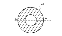
次に、円筒形の鋳型40を作成した場合を例に採って鋳型40の形状を説明する。
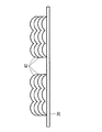
図2は鋳型40の上面図である。図3は鋳型40を図2中のA−Bの線で切り取った断面図であり、この状態では積層による層42間の段差形状は取り除かれており、鋳型40として用いることが出来る。図4は、図3と同様の図であるが、ここでは図3の場合よりも高粘度の高分子溶液を用いて作成した鋳型40の断面図である。
ここで、作成した鋳型40の段差の評価方法について説明する。
作成した鋳型40の段差は、例えば、以下の工程1から4の方法で算出する。即ち、
工程1.作成した鋳型40の側面にガラススケールを当て、鋳型40に対して水平方向からデジタルカメラで写真を撮影する。
工程2.撮影した写真をコンピュータで解析し、鋳型40側面に積層によって生じる段差の凹部の深さの画素数を計測する。
工程3.撮影した写真中のガラススケールの1mmに相当する画素数と、凹部の深さの画素数を比較し、凹部の深さを計算する。
工程4.工程2から3を繰り返して10箇所の凹部の深さを計算し、その平均値を算出する。
Next, the shape of the
FIG. 2 is a top view of the
Here, a method for evaluating the level difference of the created
The level difference of the created
Step 2. The photograph taken is analyzed by a computer, and the number of pixels at the depth of the concave portion of the step formed by the lamination on the side surface of the
Step 3. The number of pixels corresponding to 1 mm of the glass scale in the photograph taken is compared with the number of pixels of the depth of the recess, and the depth of the recess is calculated.
Step 4. Steps 2 to 3 are repeated to calculate the depth of the 10 recesses, and the average value is calculated.
(具体例1)
吐出時の粘度を400mPa・sに調整したポロキサマー407水溶液を用いて、接触角が110°であるPET基材に対し、空圧ディスペンサ35で内径18mm、外径23mm、高さ17mmの円筒形の鋳型40を積層造形した。
その結果、積層によって生じる層42間の段差の凹部の深さが0.38mmの鋳型40を作成できた。
(Specific example 1)
Using a poloxamer 407 aqueous solution whose viscosity at the time of ejection was adjusted to 400 mPa · s, a cylindrical substrate having an inner diameter of 18 mm, an outer diameter of 23 mm, and a height of 17 mm was applied to a PET substrate having a contact angle of 110 ° by a
As a result, a
次に、高分子溶液が濡れ広がる基材と濡れ広がらない基材による、高分子溶液の吐出結果を示す。
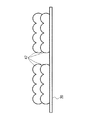
図5は、高分子溶液が濡れ広がらない、接触角が110°であるPET基材上に高分子溶液を吐出して幅1cm、長さ10cmの線Lを描画した様子を示す図である。また、図6は、同じ吐出条件において、高分子溶液が濡れ広がるステージ20の基材上に高分子溶液を吐出して線を描画した様子を示す図である。高分子溶液が濡れ広がる基材として、ここではステンレスを用いた。接触角は40°であった。
高分子溶液を濡れ広がる基材に吐出した場合、高分子溶液は、描画した線Lの形に比例せずに不規則に濡れ広がる。そのため、鋳型40を積層造形しようとした際に、一層目のゲルの層42を形成することができない。そのため、高分子溶液が濡れ広がる基材を用いると鋳型40を形成することはできない。
PET基材およびステンレス基材上で同じ吐出条件で高分子溶液を吐出したところ、PET基材上では1.0mm幅で形成できた線が、ステンレス基材上では、太い部分では幅が3.2mmであった。
Next, the discharge result of the polymer solution by the base material in which the polymer solution spreads and the base material in which the polymer solution does not spread will be shown.
FIG. 5 is a diagram showing a state in which a line L having a width of 1 cm and a length of 10 cm is drawn by discharging the polymer solution onto a PET base material having a contact angle of 110 ° where the polymer solution is not wetted and spread. FIG. 6 is a diagram illustrating a state in which a line is drawn by discharging the polymer solution onto the base material of the
When the polymer solution is discharged onto the substrate spreading wet, the polymer solution spreads irregularly without being proportional to the shape of the drawn line L. Therefore, the
When the polymer solution was discharged on the PET base material and the stainless steel base material under the same discharge conditions, a line that could be formed with a width of 1.0 mm on the PET base material had a width of 3. It was 2 mm.
次に、吐出時の粘度が500mPa・sより大きい高分子溶液を用いて造形した場合について説明する。
(具体例2)
ここでは、吐出時の粘度が1500mPa・sのポロキサマー407水溶液を、前述の400mPa・s時と同様の実験系で内径18mm、外径23mm、高さ17mmの円筒形のゲル積層物を造形した。
その結果、積層によって生じる層42間の段差の凹部の深さが1.5mmのゲル積層物になった。
Next, the case where it shape | molds using the polymer solution with the viscosity at the time of discharge larger than 500 mPa * s is demonstrated.
(Specific example 2)
Here, a cylindrical gel laminate having an inner diameter of 18 mm, an outer diameter of 23 mm, and a height of 17 mm was modeled from an aqueous poloxamer 407 solution having a viscosity at the time of ejection of 1500 mPa · s in the same experimental system as that at 400 mPa · s.
As a result, a gel laminate was obtained in which the depth of the concave portion of the step between the
(具体例3)
吐出時の粘度が900mPa・sのポロキサマー407水溶液を、前述の400mPa・s時と同様の実験系で内径18mm、外径23mm、高さ17mmの円筒形のゲル積層物を造形した。
その結果、積層によって生じる層間の段差の凹部の深さが1.2mmの造形物になった。
本出願人の検討によれば、積層によって生じる層42間の段差が成形物に転写されるのを防止するには、高分子溶液の粘度が500mPa・s以下が望ましく、また、その高分子溶液でゲルの層を形成するためには、ステージ20用に高分子溶液が濡れ広がらない基材を選択することが必須条件であることが分かった。
(Specific example 3)
A poloxamer 407 aqueous solution having a viscosity at the time of discharge of 900 mPa · s was formed into a cylindrical gel laminate having an inner diameter of 18 mm, an outer diameter of 23 mm, and a height of 17 mm in the same experimental system as that at 400 mPa · s.
As a result, the depth of the recessed portion of the step between the layers generated by the lamination became a shaped article having a thickness of 1.2 mm.
According to the study by the present applicant, in order to prevent the step between the
第2の実施形態
図1に示す積層造形装置1を用いて、ステージ20をPTFE基材にして鋳型40を造形した。
(具体例)
即ち、第1の実施形態と同様の吐出条件、粘度400mPa・sで内径18mm、外径23mm、高さ17mmの円筒形の鋳型40を積層造形した。
その結果、接触角が130°であり、積層によって生じる層間の段差の凹部の深さが0.38mmの鋳型40を作成できた。
また、PTFE基材では、接触角がPETと比べて大きく、1層目の土台を微細に造形することが出来た。
PET基材とPTFE基材において、同じ吐出条件で一本の線を描画したところ、PET基材上で1.0mm幅であり、PTFE基材上では0.91mmであった。
以上より、PTFE基材では1層目の土台を微細に形成できることが分かった。
Second Embodiment Using the
(Concrete example)
That is, a
As a result, a
Further, the PTFE base material has a larger contact angle than that of PET, and the first layer base could be finely shaped.
When a single line was drawn on the PET substrate and the PTFE substrate under the same discharge conditions, the width was 1.0 mm on the PET substrate and 0.91 mm on the PTFE substrate.
From the above, it was found that the base of the first layer can be formed finely in the PTFE base material.
第3の実施形態
高分子材料は、低粘度であるほど寸法精度を向上できるが、吐出後に流動しやすく、流動の量が寸法精度に影響する。
吐出された高分子溶液をゲル化するための加熱手段としてステージ20を加熱する場合、下層部と比べて上層部の温度が低くなり易い。そのため積層を続けて積層物(三次元構造物)が高くなった場合、上層部ほど、高分子溶液を吐出してからゲル化するまでの時間が長くなる、つまり1層分積層するための時間が長くなる問題がある。この場合、高分子溶液が流動する量も多くなる。
Third Embodiment As the polymer material has a lower viscosity, the dimensional accuracy can be improved, but it tends to flow after ejection, and the amount of flow affects the dimensional accuracy.
When the
そこで、1層分積層するための時間を一定化させ、流動する量を安定させるため、加熱機構22として次に示す恒温槽50を用いた積層造形装置1で鋳型40を作成することが好適である。
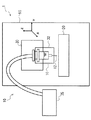
図7は、本発明の第3の実施形態にかかる鋳型の作成方法を実施する積層造形装置1を概略的に示す図である。
本実施形態では、雰囲気をゾル−ゲル転移温度より高い温度環境にする恒温槽50を用いる。
積層造形装置1は、高分子溶液を吐出する液滴吐出機構10、吐出された高分子溶液を着弾させるステージ20、液滴吐出機構10の液滴吐出手段12とステージ20とを相対移動させる駆動部30、吐出前の高分子溶液を冷却する吐出溶液冷却手段32、恒温槽50、などを備える。
恒温槽50は、内部空間の温度を一定に保持する装置である。恒温槽50の設定温度を高分子溶液のゾル−ゲル転移温度以上に設定し、保持する。
Therefore, in order to stabilize the time for laminating one layer and stabilize the flowing amount, it is preferable to create the
FIG. 7 is a diagram schematically showing an
In the present embodiment, a
The
The
液滴吐出機構10、ステージ20、駆動部30、吐出溶液冷却手段32は第1の実施形態と同様であるが、本実施形態では、少なくともステージ20、駆動部30、吐出溶液冷却手段32、液滴吐出機構10の液滴吐出手段12が恒温槽50の内部に収容されている。
ゲルの成形物を形成する手段は第1の実施形態と同様である。
即ち、吐出溶液冷却手段32で冷却された高分子溶液をステージ20上に吐出する。ステージ20及び恒温槽50内の空間温度がゾル−ゲル転移温度より高い温度のため、吐出された高分子溶液がゲル化する。
The
The means for forming the gel molding is the same as in the first embodiment.
That is, the polymer solution cooled by the discharge solution cooling means 32 is discharged onto the
本実施形態では、恒温槽50を用い造形物を加熱するため、積層時に上層部の温度が低くなる問題がなく、高く積層を続けても1層分の積層に掛かる待ち時間を一定にできる。
(具体例)
粘度150mPa・sのポロキサマー407水溶液を用いて、ディスペンサ35でPTFE基材上に内径18mm、外径23mm、高さ17mmの円筒形の鋳型40を積層造形した結果、積層によって生じる層間の段差の凹部の深さが0.27mmの鋳型40を作成できた。
In the present embodiment, since the shaped object is heated using the
(Concrete example)
Using an aqueous solution of poloxamer 407 having a viscosity of 150 mPa · s, a concave part of a step between layers generated by lamination as a result of laminating a
以上、本発明の実施形態について説明したが、その効果を以下にまとめて記載する。即ち、本実施形態において、
(1)鋳型を、高分子溶液が濡れ広がらないステージ上で形成するため、土台が安定し、鋳型の寸法精度が高くなる。
(2)高分子溶液の粘度が500mPa・s以下であることにより、流動性が高まり、鋳型の平滑性が高まる。
As mentioned above, although embodiment of this invention was described, the effect is summarized and described below. That is, in this embodiment,
(1) Since the mold is formed on a stage where the polymer solution is not wetted and spread, the foundation is stable and the dimensional accuracy of the mold is increased.
(2) When the viscosity of the polymer solution is 500 mPa · s or less, the fluidity is enhanced and the smoothness of the mold is enhanced.
(3)ステージの基材として、プラスチック、もしくは撥液処理したガラス、撥液処理した金属およびそれらの組み合わせの基材を用いるため、高分子溶液がステージで濡れ広がらなくなり、土台が安定し、鋳型の寸法精度が高くなる。
(4)高分子溶液をステージ上に吐出した後、同一地点に上から高分子溶液を吐出するまでの時間間隔を5秒以上空けることにより、下層の高分子溶液がゲル化してから吐出することで、ゲルの層を上方向に積層造形することができる。
(5)恒温槽内部の温度分布が一定な環境で鋳型を積層造形することにより、積層の高さによらず吐出した高分子溶液のゲル化時間が一定になり、形成した鋳型の寸法精度が向上する。
(3) Since the base material for the stage is plastic, liquid-repellent-treated glass, liquid-repellent-treated metal, or a combination thereof, the polymer solution does not spread on the stage, the base is stable, the mold Dimensional accuracy increases.
(4) Discharge after the polymer solution in the lower layer has gelled by leaving a time interval of 5 seconds or more after discharging the polymer solution on the stage until discharging the polymer solution from above to the same point. Thus, the gel layer can be layered in the upward direction.
(5) By mold-molding the mold in an environment where the temperature distribution inside the thermostatic chamber is constant, the gelation time of the discharged polymer solution is constant regardless of the height of the stack, and the dimensional accuracy of the formed mold is improved. improves.
1・・・積層造形装置、10・・・液滴吐出機構、12・・・液滴吐出手段、20・・・ステージ、22・・・加熱機構(ヒーター)、30・・・駆動部、32・・・吐出溶液冷却手段、35・・・ディスペンサ、40・・・鋳型、42・・・層、50・・・恒温槽。
DESCRIPTION OF
Claims (6)
ゾル−ゲル転移温度より低い温度に保持した高分子溶液を液滴吐出機構により前記ステージに吐出する工程と、
前記ステージに吐出された前記高分子溶液をゾル−ゲル転移温度より高い温度に維持してゲル化する工程と、
前記液滴吐出機構と前記ステージとを相対移動させて、前記相対移動の軌跡の形状のゲルの層をステージ上に形成する工程と、
前記液滴吐出機構でゲルの層の上にさらに高分子溶液を吐出する工程と、を有し、ゲルを積層造形することを特徴とする鋳型の作成方法。 Using a polymer solution having a sol-gel transition temperature that is solated at a temperature lower than the sol-gel transition temperature and gelled at a temperature higher than the sol-gel transition temperature, a predetermined contact angle at which the polymer solution does not wet and spread On a stage made of a base material to be formed, the stage or atmosphere is formed in a temperature environment higher than the sol-gel transition temperature.
A step of discharging a polymer solution held at a temperature lower than the sol-gel transition temperature onto the stage by a droplet discharge mechanism;
Maintaining the polymer solution discharged to the stage at a temperature higher than the sol-gel transition temperature and gelling;
Relatively moving the droplet discharge mechanism and the stage to form a gel layer on the stage in the shape of the locus of relative movement;
And a step of further discharging a polymer solution onto the gel layer by the droplet discharge mechanism, wherein the gel is layered and formed.
前記高分子溶液を前記ステージに吐出する工程において吐出される高分子溶液の粘度は、500mPa・sより小さいことを特徴とする鋳型の作成方法。 In the manufacturing method of the casting_mold | template described in Claim 1,
A method for producing a mold, wherein the viscosity of the polymer solution discharged in the step of discharging the polymer solution to the stage is less than 500 mPa · s.
前記基材の表面は、プラスチック、もしくは撥液処理したガラス、撥液処理した金属、及びそれらの組み合わせからなることを特徴とする鋳型の作成方法。 In the manufacturing method of the casting_mold | template described in Claim 1,
A method for producing a mold, wherein the surface of the substrate is made of plastic or glass subjected to a liquid repellent treatment, a metal subjected to a liquid repellent treatment, and a combination thereof.
前記相対移動の軌跡の形状のゲルの層をステージ上に形成する工程において、高分子溶液を前記ステージ上に吐出した後、同一地点に上から高分子溶液を吐出するまでの時間間隔は5秒以上であることを特徴とする鋳型の作成方法。 In the manufacturing method of the casting_mold | template described in Claim 1,
In the step of forming the gel layer having the shape of the locus of relative movement on the stage, the time interval from the time when the polymer solution is discharged onto the stage to the time when the polymer solution is discharged from above onto the same point is 5 seconds. A method for producing a mold characterized by the above.
前記各工程は、恒温槽の中で行われることを特徴とする鋳型の作成方法。 In the manufacturing method of the casting_mold | template described in Claim 1,
Each of the above steps is performed in a thermostatic chamber.
前記所定の接触角は、90°以上であることを特徴とする鋳型の作成方法。 In the manufacturing method of the casting_mold | template described in Claim 1,
The predetermined contact angle is 90 ° or more.
Priority Applications (1)
| Application Number | Priority Date | Filing Date | Title |
|---|---|---|---|
| JP2016017539A JP6733194B2 (en) | 2016-02-01 | 2016-02-01 | How to make a mold |
Applications Claiming Priority (1)
| Application Number | Priority Date | Filing Date | Title |
|---|---|---|---|
| JP2016017539A JP6733194B2 (en) | 2016-02-01 | 2016-02-01 | How to make a mold |
Publications (2)
| Publication Number | Publication Date |
|---|---|
| JP2017136708A true JP2017136708A (en) | 2017-08-10 |
| JP6733194B2 JP6733194B2 (en) | 2020-07-29 |
Family
ID=59565256
Family Applications (1)
| Application Number | Title | Priority Date | Filing Date |
|---|---|---|---|
| JP2016017539A Active JP6733194B2 (en) | 2016-02-01 | 2016-02-01 | How to make a mold |
Country Status (1)
| Country | Link |
|---|---|
| JP (1) | JP6733194B2 (en) |
Cited By (1)
| Publication number | Priority date | Publication date | Assignee | Title |
|---|---|---|---|---|
| JP2017226207A (en) * | 2016-06-15 | 2017-12-28 | 株式会社リコー | Cast, cast forming method and casting method |
Citations (3)
| Publication number | Priority date | Publication date | Assignee | Title |
|---|---|---|---|---|
| JP2003011237A (en) * | 2001-07-03 | 2003-01-15 | Kuraray Co Ltd | Method for producing three-dimensional shaped article |
| WO2015049834A1 (en) * | 2013-10-03 | 2015-04-09 | コニカミノルタ株式会社 | Three-dimensional shaping device and three-dimensional shaping method |
| JP2017136829A (en) * | 2016-02-01 | 2017-08-10 | 株式会社リコー | Method for creating mold, mold creation device, and method for molding model material |
-
2016
- 2016-02-01 JP JP2016017539A patent/JP6733194B2/en active Active
Patent Citations (3)
| Publication number | Priority date | Publication date | Assignee | Title |
|---|---|---|---|---|
| JP2003011237A (en) * | 2001-07-03 | 2003-01-15 | Kuraray Co Ltd | Method for producing three-dimensional shaped article |
| WO2015049834A1 (en) * | 2013-10-03 | 2015-04-09 | コニカミノルタ株式会社 | Three-dimensional shaping device and three-dimensional shaping method |
| JP2017136829A (en) * | 2016-02-01 | 2017-08-10 | 株式会社リコー | Method for creating mold, mold creation device, and method for molding model material |
Cited By (1)
| Publication number | Priority date | Publication date | Assignee | Title |
|---|---|---|---|---|
| JP2017226207A (en) * | 2016-06-15 | 2017-12-28 | 株式会社リコー | Cast, cast forming method and casting method |
Also Published As
| Publication number | Publication date |
|---|---|
| JP6733194B2 (en) | 2020-07-29 |
Similar Documents
| Publication | Publication Date | Title |
|---|---|---|
| US11097532B2 (en) | Method for making mold, method for molding model material, and mold making apparatus | |
| US20200269320A1 (en) | Molding method and apparatus, particularly applicable to metal and/or ceramics | |
| Udofia et al. | A guiding framework for microextrusion additive manufacturing | |
| JP2016104555A (en) | Selective zone temperature control built plate | |
| US20180015670A1 (en) | Process for forming polymeric parts under vacuum conditions | |
| KR20160091329A (en) | 3d printing method using slip | |
| JP2017503678A5 (en) | ||
| JP5669908B2 (en) | Manufacturing method for forming a three-dimensional object with less warpage by using a cooling method | |
| US11097491B1 (en) | Mask-based partition preheating device and partition preheating method thereof | |
| CN104626592B (en) | The former and its forming method of a kind of three-dimensional model | |
| CN107283819B (en) | A kind of 3D printing equipment and Method of printing towards high molecular weight silicon rubber | |
| WO2017040188A1 (en) | Additive manufacturing products and processes | |
| KR102520064B1 (en) | Additive Manufacturing with Selective Liquid Cooling | |
| JP7191959B2 (en) | Apparatus for additive manufacturing of three-dimensional objects | |
| US20210206104A1 (en) | Build unit for three-dimensional printer | |
| JP2013022964A (en) | Apparatus and method for manufacturing three-dimensional object in layers, polymer powder and mold | |
| Bayram et al. | Biofabrication of gelatin tissue scaffolds with uniform pore size via microbubble assembly | |
| CN105345984A (en) | High molecular material surface with T-shaped microstructure and preparation method and application thereof | |
| JP2017136708A (en) | Method for creating mold | |
| JP6874349B2 (en) | Mold making method, mold making device, and model material molding method | |
| JP6524845B2 (en) | Three-dimensional modeling device | |
| US10894354B2 (en) | SLA additive manufacturing using frozen supports of non-SLA material | |
| JP2017160471A (en) | Method of producing three-dimensional modeled product, apparatus for producing three-dimensional modeled product, and three-dimensional modeled product | |
| JP2005261286A (en) | Apparatus for producing food and method for producing food | |
| US10414088B2 (en) | Platform structure for use in low-temperature manufacturing of scaffold for use in tissue engineering and method of low-temperature manufacturing scaffold for use in tissue engineering |
Legal Events
| Date | Code | Title | Description |
|---|---|---|---|
| A621 | Written request for application examination |
Free format text: JAPANESE INTERMEDIATE CODE: A621 Effective date: 20190109 |
|
| A131 | Notification of reasons for refusal |
Free format text: JAPANESE INTERMEDIATE CODE: A132 Effective date: 20200128 |
|
| A521 | Request for written amendment filed |
Free format text: JAPANESE INTERMEDIATE CODE: A523 Effective date: 20200327 |
|
| TRDD | Decision of grant or rejection written | ||
| A01 | Written decision to grant a patent or to grant a registration (utility model) |
Free format text: JAPANESE INTERMEDIATE CODE: A01 Effective date: 20200609 |
|
| A61 | First payment of annual fees (during grant procedure) |
Free format text: JAPANESE INTERMEDIATE CODE: A61 Effective date: 20200622 |
|
| R151 | Written notification of patent or utility model registration |
Ref document number: 6733194 Country of ref document: JP Free format text: JAPANESE INTERMEDIATE CODE: R151 |