JP6524845B2 - Three-dimensional modeling device - Google Patents
Three-dimensional modeling device Download PDFInfo
- Publication number
- JP6524845B2 JP6524845B2 JP2015152965A JP2015152965A JP6524845B2 JP 6524845 B2 JP6524845 B2 JP 6524845B2 JP 2015152965 A JP2015152965 A JP 2015152965A JP 2015152965 A JP2015152965 A JP 2015152965A JP 6524845 B2 JP6524845 B2 JP 6524845B2
- Authority
- JP
- Japan
- Prior art keywords
- modeling
- dimensional
- layer
- support
- curing material
- Prior art date
- Legal status (The legal status is an assumption and is not a legal conclusion. Google has not performed a legal analysis and makes no representation as to the accuracy of the status listed.)
- Expired - Fee Related
Links
Images


Description
本発明は立体造形装置に関する。 The present invention relates to a three-dimensional modeling apparatus.
立体造形物(三次元造形物)を造形する立体造形装置(三次元造形装置)として、例えば積層造形法で造形するものが知られている。これは、層状造形物(以下、「造形層」ともいう。)を積層して立体造形物を造形する。 As a three-dimensional modeling apparatus (three-dimensional modeling apparatus) that models a three-dimensional model (three-dimensional model), for example, one that models by a layered modeling method is known. This forms a three-dimensional object by laminating a layered object (hereinafter, also referred to as "the forming layer").
従来、溶融状態にある未硬化樹脂を、容器内の水や油などの冷却液(硬化液)中にヘッドから吐出して、未硬化樹脂を冷却固化することで立体造形物を造形するものが知られている(特許文献1)。 Conventionally, a three-dimensional object is formed by discharging an uncured resin in a molten state from a head into a cooling liquid (curing liquid) such as water or oil in a container to cool and solidify the uncured resin. It is known (patent document 1).
ところで、容器内に溜められた硬化液の表面に未硬化樹脂を吐出するようにした場合、硬化液の液面が揺れ易く、未硬化樹脂の着弾位置精度が低下して立体造形物の精度が低下し、あるいは、揺れた液面が安定するまでに造形を待たなければならず、造形に無駄な時間がかかるという課題がある。 By the way, when non-hardened resin is discharged on the surface of the hardening liquid stored in the container, the liquid level of the hardening liquid tends to shake, the landing position accuracy of the unhardened resin decreases, and the accuracy of the three-dimensional object There is a problem that it is necessary to wait for shaping until the liquid level which is lowered or shaken becomes stable, and it takes time for shaping.
本発明は上記の課題に鑑みてなされたものであり、立体造形物の精度を向上することを目的とする。 This invention is made in view of said subject, and it aims at improving the precision of a three-dimensional model.
上記の課題を解決するため、本発明の請求項1に係る立体造形装置は、
層状造形物を積層して立体造形物を造形する立体造形装置であって、
液状の硬化材層を形成し、前記硬化材層に対して造形材を供給し、前記硬化材層の前記硬化材で前記造形材が固化された前記層状造形物を形成する手段を備え、
前記液状の硬化材が収容された造形槽内で、
前記立体造形物が造形される造形ステージを下降させて、前記造形ステージの表面又は前記層状造形物の表面を前記液状の硬化材内に浸漬した後、
造形ステージを上昇させて、前記造形ステージの表面又は前記層状造形物の表面を前記液状の硬化材内から出し、前記造形ステージの表面又は前記層状造形物の表面に薄膜状の前記硬化材層を形成する
構成とした。
In order to solve said subject, the three-dimensional model | molding apparatus which concerns on Claim 1 of this invention is
It is a three-dimensional shaping apparatus which forms a three-dimensional shaped object by laminating a layered shaped object,
A means for forming a liquid curing material layer, supplying a modeling material to the curing material layer, and forming the layered shaped object in which the modeling material is solidified with the curing material of the curing material layer;
In the shaping tank in which the liquid curing material is contained,
After lowering the forming stage on which the three-dimensional object is formed and immersing the surface of the forming stage or the surface of the layered object in the liquid curing material,
The shaping stage is raised to bring out the surface of the shaping stage or the surface of the layered shaped article from the inside of the liquid curing material, and the thin film-like curing material layer is formed on the surface of the shaping stage or the surface of the layered shaped article It was set as the structure to form .
本発明によれば、立体造形物の精度を向上することができる。 According to the present invention, the accuracy of a three-dimensional object can be improved.
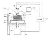
以下、本発明の実施の形態について添付図面を参照して説明する。本発明の第1実施形態について図1を参照して説明する。図1は同実施形態に係る立体造形装置の模式的説明図である。 Hereinafter, embodiments of the present invention will be described with reference to the attached drawings. A first embodiment of the present invention will be described with reference to FIG. FIG. 1 is a schematic explanatory view of a three-dimensional modeling apparatus according to the same embodiment.
この立体造形装置は、立体造形物108が造形される造形槽101を備えている。造形槽101内には、立体造形物(積層造形物)108が造形される造形ステージ104が昇降可能に配置されている。造形ステージ104は、造形槽101外に配置されたアクチュエータ103により昇降される。
The three-dimensional shaping apparatus includes a
造形槽101の上方には、硬化材供給手段113と、造形材供給手段106と、サポート材供給手段112とが配置されている。
Above the
硬化材供給手段113は、液状の硬化材(硬化剤を含む。)102を滴下して供給する手段である。造形材供給手段106は、硬化材102で固化される造形材(造形剤を含む。)107を吐出して供給する。サポート材供給手段112は、硬化材102で固化されるサポート材(サポート剤を含む。)110を吐出して供給する手段である。
The curing material supply means 113 is a means for dropping and supplying a liquid curing material (including a curing agent) 102. The modeling material supply means 106 discharges and supplies the modeling material (including the modeling agent) 107 solidified by the
硬化材供給手段113によって造形ステージ104の表面、あるいは、既存の造形層108aの表面に液状の硬化材102を滴下して供給することで、液状の硬化材102が造形ステージ104の表面、あるいは、既存の造形層108aの表面で濡れ広がって薄膜化した硬化材層102aが形成される。
The
つまり、硬化材供給手段113は、液状の硬化材を供給する手段を構成している。 That is, the curing material supply means 113 constitutes a means for supplying a liquid curing material.
造形材供給手段106によって硬化材層102aの所要の位置に造形材107を吐出することで、造形材107が硬化材層102aの硬化材102によって固化されて、層状造形物である造形層108aが形成される。
By discharging the
つまり、造形材供給手段106は、液状の硬化材層に対して造形材を供給する手段を構成している。なお、本実施形態では、硬化材102(造形材層102a)の温度は造形材107の凝固点よりも低く、造形材107が硬化材層102aに着弾することで硬化材102によって冷却固化され、造形層108aが形成される。
That is, the modeling material supply means 106 constitutes a means for supplying the modeling material to the liquid curing material layer. In the present embodiment, the temperature of the curing material 102 (the
サポート材供給手段112によって硬化材層102aの所要の位置にサポート材110を吐出することで、サポート材110が硬化材層102aの硬化材102によって固化されて、層状のサポート層111aが形成される。
By discharging the
つまり、サポート材供給手段112は、硬化材層に対してサポート材を供給する手段を構成している。なお、本実施形態では、硬化材102(造形材層102a)の温度はサポート材110の凝固点よりも低く、サポート材110が硬化材層102aに着弾することで硬化材102によって冷却固化され、サポート層111aが形成される。
That is, the support material supply means 112 constitutes a means for supplying the support material to the curing material layer. In the present embodiment, the temperature of the curing material 102 (the
本実施形態では、サポート材供給手段112によってサポート材110を供給してサポート層111aを形成し、このサポート層111aで造形層108aのオーバーハング部を支えるサポート部111、又は、造形する立体造形物108を包括して支えるサポート部111を形成する。
In the present embodiment, the
ここで、硬化材供給手段113、造形材供給手段106及びサポート材供給手段112は、造形槽101の造形ステージ104の表面に沿う方向に配置された駆動軸部材121に保持されている。
Here, the curing material supply means 113, the modeling material supply means 106, and the support material supply means 112 are held by the
そして、駆動軸部材121がアクチュエータ105によって回転駆動されることで、硬化材供給手段113、造形材供給手段106及びサポート材供給手段112が造形ステージ104の表面に沿って往復移動される。なお、硬化材供給手段113、造形材供給手段106及びサポート材供給手段112の移動走査機構はこれに限られない。
Then, as the
アクチュエータ103による造形ステージ104の昇降、アクチュエータ105による硬化材供給手段113、造形材供給手段106及びサポート材供給手段112の往復移動、硬化材供給手段113による硬化材102の供給制御、造形材供給手段106による造形材107の供給制御、サポート材供給手段112によるサポート材110の供給制御などは制御装置109によって行われる。
Up and down movement of the forming
また、硬化材供給手段113は、造形材供給手段106及びサポート材供給手段112を挟んで両側に配置されている。 Moreover, the hardening material supply means 113 is arrange | positioned on both sides on both sides of the modeling material supply means 106 and the support material supply means 112. As shown in FIG.
これにより、造形材供給手段106がいずれの方向に移動するときでも、造形材供給手段106による造形材107の供給に先立って硬化材102を供給することができる。
Thus, the hardening
なお、硬化材供給手段113は、ディスペンサを一列に並べたもの、液体吐出ヘッドなどで構成することができる。また、硬化材102を供給する筆状の先端部を造形層108aに接触させながら硬化材102を表面に塗布する機構とすることもできる。
In addition, the hardening material supply means 113 can be comprised by what arranged the dispenser in 1 row, a liquid discharge head, etc. FIG. Alternatively, the brush-like tip for supplying the
また、造形材供給手段106及びサポート材供給手段112は、液体吐出ヘッドやディスペンサで構成することができる。また、液体吐出ヘッドを使用する場合、同じヘッドに配置されている異なるノズル列をそれぞれ造形材供給手段106、サポート材供給手段112として使用することができる。 In addition, the modeling material supply means 106 and the support material supply means 112 can be configured by a liquid discharge head or a dispenser. Moreover, when using a liquid discharge head, the different nozzle row arrange | positioned at the same head can be used as the modeling material supply means 106 and the support material supply means 112, respectively.
ここで、硬化材102は、造形材107を冷却固化して硬化させる性質を持ち、且つ、硬化材102によって硬化した造形材107は相変化によって軟化する性質を持っている。好ましくは、硬化材102は造形材107を造形材107の凝固点以下の温度に冷却して凝固させる凝固材であり、硬化材102によって凝固した造形材107は温度上昇によって軟化する。
Here, the
硬化材102としては、凝固点が造形材107の凝固点よりも低くなるように濃度を調節し、造形材107の凝固点よりも温度を低く、かつ、硬化材102の凝固点よりも温度を高く制御した液体、例えば、冷却したグリセリン水溶液を使用できる。また、硬化材102としては、沸点が造形材107の凝固点よりも温度の低い液体、例えば液体窒素を使用することができる。また、造形材107の凝固点よりも温度が低い気体、例えば冷却用炭酸ガスを使用することができる。
A liquid in which the concentration is adjusted so that the solidification point is lower than the solidification point of the shaping
言い換えれば、立体造形物の融点又はガラス転移点が温度T[℃]であるとき、温度Tが造形環境又は立体造形物の使用環境温度よりも低い温度であり、硬化材は、温度T以下に冷却した凝固点が温度Tより低い物質、又は、沸点が温度T以下の物質である。 In other words, when the melting point or glass transition temperature of the three-dimensional object is the temperature T [° C.], the temperature T is lower than the use environment temperature of the forming environment or the three-dimensional object, and the curing material is at the temperature T or lower It is a substance whose cooled freezing point is lower than the temperature T or a substance whose boiling point is lower than the temperature T.
サポート材110は、硬化材102によって冷却固化される性質を有し、立体造形物108から分離可能な物性のものを使用する。例えば、立体造形物108が水やアルコール等に溶けない部材であれば、サポート材110は水やアルコール等に溶ける部材、物理的な力を加えることで分離可能な離型材を含んだ部材を使用する。
The
サポート材110は、造形層108aないし立体造形物108の融点又はガラス転移点の温度よりも融点が低い部材を使用することができる。これにより、サポート材110の融点温度で加熱することで、サポート層111aのみを容易に除去することができる。
As the
例えば、サポート材110として水又は水を主成分とする液体を使用することで、数℃の加熱を加えることによってサポート層111aを溶融除去することができる。
For example, by using water or a liquid containing water as the main component as the
次に、この立体造形装置による造形動作について説明する。 Next, the modeling operation by this three-dimensional modeling apparatus will be described.
この装置で造形を行うときには、硬化材供給手段113によって造形ステージ104の表面に硬化材102を滴下し、造形ステージ104の表面に硬化材102が濡れ広がった薄膜状の硬化材層102aを形成する。
When modeling is performed with this apparatus, the curing
そして、造形材供給手段106及びサポート材供給手段112を移動させて、硬化材層102aの所要の位置に造形材107又はサポート材110を吐出して供給する。
And the modeling material supply means 106 and the support material supply means 112 are moved, and the
硬化材層102aの所望の位置に吐出されて着弾した造形材107は、硬化材102によって即時に凝固する(冷却固化される)ことで、目的形状の造形層108aが形成される。同じく、硬化材層102aの所望の位置に吐出されて着弾したサポート材110は、硬化材102によって即時に凝固する(冷却固化される)ことで、目的形状のサポート層111aが形成される。
The shaping
これにより、造形ステージ104の表面に、1層目の造形層108aとサポート層111aが形成される。
As a result, the
その後、1層目の造形層108a及びサポート層111aの表面上に硬化材供給手段113によって硬化材102を滴下して、1層目の造形層108a及びサポート層111aの表面に硬化材層102aを形成する。
Thereafter, the curing
そして、1層目と同様に、造形材供給手段106及びサポート材供給手段112を移動させて、硬化材層102aの所要の位置に造形材107又はサポート材110を吐出して供給し、2層目の造形層108a及びサポート層111aを形成する。
Then, similarly to the first layer, the modeling material supply means 106 and the support material supply means 112 are moved to discharge and supply the
この動作を繰り返して、造形ステージ104上に造形層108aが積層された立体造形物108を造形するとともに、サポート層111aが積層されたサポート部111を形成する。
While repeating this operation, the three-
造形層108aを形成する造形データは、造形する立体造形物108をスライスしたスライスデータとして制御装置109に与えられ、制御装置109が造形データに従って造形材供給手段106の位置及び供給(吐出)を制御することで、造形データに従った造形層108aが形成される。
The formation data forming the
サポート層111aを形成するための造形データも、造形層108aの造形データと同様にスライスデータとして与えられ、制御装置109がサポート材供給手段112の位置及び供給を制御することサポート層111aが形成される。
The modeling data for forming the
このように、液状の硬化材層を形成し、この液状の硬化材層に硬化材で固化される造形材を供給して層状造形物を形成することで、高精度の立体造形物を形成することができる。 In this manner, a liquid hardening material layer is formed, and a modeling material solidified with the hardening material is supplied to the liquid hardening material layer to form a layered object, thereby forming a three-dimensional object with high accuracy. be able to.
また、硬化材層を形成して、当該硬化材層に造形材を吐出(供給)することで、硬化材の沸点が造形材の温度以下である場合(急激な沸騰が起こる条件)であっても、硬化材層の厚み(液膜の厚み)が薄いので、急激な沸騰が起こらない。この点でも、層状造形物の精度が高くなり、高精度の立体造形物を形成することができる。 In addition, when the curing material layer is formed and the modeling material is discharged (supplied) to the curing material layer, the boiling point of the curing material is equal to or lower than the temperature of the modeling material (a condition in which rapid boiling occurs) Also, since the thickness of the hardening material layer (the thickness of the liquid film) is thin, rapid boiling does not occur. Also in this respect, the accuracy of the layered object can be enhanced, and a three-dimensional object with high accuracy can be formed.
次に、本発明の第2実施形態について図2を参照して説明する。図2は同実施形態に係る立体造形装置の模式的説明図である。 Next, a second embodiment of the present invention will be described with reference to FIG. FIG. 2 is a schematic explanatory view of the three-dimensional modeling apparatus according to the embodiment.
本実施形態では、造形ステージ104には、硬化材層102aに振動を付与する手段である超音波振動子122を備えている。超音波振動子122は制御装置109によって駆動される。超音波振動子122を駆動することで、造形ステージ104を介して硬化材層102aに振動を与えることができる
In the present embodiment, the
超音波振動子122を動作させて、造形ステージ104上の硬化材層102aに超音波振動を付与することで、硬化材層102a中に微細な気泡を発生させる。
The
これにより、硬化材層102aに過熱が起こりにくく、沸点が低い硬化材102に造形材107が着弾したときに、急激な沸騰を起こりにくくすることができる。
Thus, when the
次に、本発明の第3実施形態について図3を参照して説明する。図3は同実施形態に係る立体造形装置の模式的説明図である。 Next, a third embodiment of the present invention will be described with reference to FIG. FIG. 3 is a schematic explanatory view of the three-dimensional modeling apparatus according to the embodiment.
本実施形態では、造形材供給手段106及びサポート材供給手段112は、前記第1実施形態と同様に駆動軸部材121に保持されている。
In the present embodiment, the modeling material supply means 106 and the support material supply means 112 are held by the
一方、硬化材供給手段113は、造形槽101の造形ステージ104の表面に沿う方向に配置された駆動軸部材123に保持され、駆動軸部材123がアクチュエータ115によって回転駆動されることで往復移動される。アクチュエータ115は制御装置109によって駆動制御される。つまり、硬化材供給手段113は、造形材供給手段106及びサポート材供給手段112とは独立して移動させることができる。
On the other hand, the hardening material supply means 113 is held by the
この装置では、アクチュエータ115を駆動制御して硬化材供給手段113を所要の位置に移動させ、硬化材供給手段113によって造形ステージ104の表面、あるいは、造形層108a及びサポート層111aの表面上に硬化材102を滴下させて硬化材層112aを形成する。
In this apparatus, the
そして、アクチュエータ105を駆動制御して造形材供給手段106及びサポート材供給手段112を所要の位置に移動させ、造形材供給手段106及びサポート材供給手段112によって造形ステージ104表面上、又は、造形層108a及びサポート層111aの表面の硬化材層112aに対して造形材107及びサポート材110を供給する。
Then, the
例えば、硬化材供給手段113のホームポジションを図3の左端とし、造形材供給手段106及びサポート材供給手段112のホームポジションを図3の右端とする。硬化材供給手段113を右、左と往復させた後に、造形材供給手段106及びサポート材供給手段112を左、右と往復させる。 For example, the home position of the curing material supply means 113 is the left end of FIG. 3, and the home positions of the forming material supply means 106 and the support material supply means 112 are the right end of FIG. After reciprocating the curing material supply means 113 to the right and left, the shaping material supply means 106 and the support material supply means 112 are reciprocated to the left and right.
硬化材層102aの所望の位置に供給入された造形材107は、硬化材102によって即時に凝固する(冷却固化される)ことで、目的形状の造形層108aが形成される。同じく、硬化材層102aの所望の位置に供給されたサポート材110は、硬化材102によって即時に凝固する(冷却固化される)ことで、目的形状のサポート層111aが形成される。
The shaping
次に、本発明の第4実施形態について図4を参照して説明する。図4は同実施形態に係る立体造形装置の模式的説明図である。 Next, a fourth embodiment of the present invention will be described with reference to FIG. FIG. 4 is a schematic explanatory view of the three-dimensional modeling apparatus according to the embodiment.
本実施形態では、造形ステージ104は造形槽101に固定配置されている。
In the present embodiment, the
一方、アクチュエータ105は、上下方向に配置された駆動軸部材124に保持され、駆動軸部材124がアクチュエータ116で回転駆動されることで昇降(高さ方向に移動)される。アクチュエータ105が昇降することで、造形材供給手段106及びサポート材供給手段112は造形ステージ104に対して昇降する。
On the other hand, the
また、アクチュエータ105には、硬化材102を造形層108aの表面に沿う方向から供給する硬化材供給手段113を取り付けている。これにより、アクチュエータ105の昇降によって硬化材供給手段113も造形材供給手段106及びサポート材供給手段112に連動して昇降する。
Further, the
また、硬化材102を造形層108aの表面に沿う方向から供給することで、硬化材102は造形ステージ104の表面、又は、造形層108a及びサポート層111aの表面に層状化(薄膜化)され易い。
Also, by supplying the curing
この装置で造形を行うときには、アクチュエータ115を駆動制御して硬化材供給手段113を所要の位置に移動させ、硬化材供給手段113によって造形ステージ104表面上(1層目)、又は、造形層108a及びサポート層111aの表面上(2層目以降)に硬化材102を供給する。
When modeling is performed with this apparatus, the
そして、造形ステージ104の表面上、又は、造形層108a及びサポート層111aの表面上の硬化材層102aに対して、造形材供給手段106及びサポート材供給手段112によって造形材107及びサポート材110を吐出して供給する。
Then, with respect to the curing
硬化材層102aの所望の位置に着弾した造形材107は、硬化材102によって即時に凝固する(冷却固化される)ことで、目的形状の造形層108aが形成される。同じく、硬化材層102aの所望の位置に注入されたサポート材110は、硬化材102によって即時に凝固する(冷却固化される)ことで、目的形状のサポート層111aが形成される。
The shaping
そして、目的とする造形層108a及びサポート層111aを形成した後、アクチュエータ116を駆動して、造形ステージ104に対して、造形層一層分、硬化材供給手段113、造形材供給手段106、サポート材供給手段112を上昇させる。
Then, after forming the
その後、硬化材102の供給、造形材107の供給、サポート材110の供給を行って次層の造形層108a及びサポート層111aの造形を繰り返すことで、立体造形物108及びサポート部111が造形される。
Thereafter, the three-
次に、本発明の第5実施形態について図5を参照して説明する。図5は同実施形態に係る立体造形装置の模式的説明図である。 Next, a fifth embodiment of the present invention will be described with reference to FIG. FIG. 5 is a schematic explanatory view of the three-dimensional modeling apparatus according to the embodiment.
本実施形態では、硬化材供給手段113は、造形槽101の上部に固定配置され、硬化材102を造形層108aの表面に沿う方向から供給する。硬化材102を造形層108aの表面に沿う方向から供給することで、硬化材102は造形ステージ104の表面、又は、造形層108aの表面を流れて硬化材層102aが形成される。
In the present embodiment, the curing material supply means 113 is fixedly disposed on the top of the
一方、前記第1実施形態と同様に、造形ステージ104は昇降可能に配置され、造形材供給手段106及びサポート材供給手段112は造形ステージ104の表面に沿う方向に移動可能に配置されている。
On the other hand, as in the first embodiment, the
この装置で造形を行うときには、造形ステージ104を、造形ステージ104の表面に硬化材供給手段113から一層の硬化材層102aを形成する硬化材102が供給される位置まで上昇させる。そして、硬化材供給手段113から造形ステージ104の表面に硬化材102を供給して硬化材層102aを形成する。
When modeling is performed with this apparatus, the
その後、造形材供給手段106及びサポート材供給手段112を移動させて、硬化材層102aに対して造形材107及びサポート材110を吐出して供給する。
Thereafter, the modeling material supply means 106 and the support material supply means 112 are moved to discharge and supply the
硬化材層102aの所望の位置に吐出された造形材107は、硬化材102によって即時に凝固する(冷却固化される)ことで、目的形状の造形層108aが形成される。同じく、硬化材層102aの所望の位置に吐出されたサポート材110は、硬化材102によって即時に凝固する(冷却固化される)ことで、目的形状のサポート層111aが形成される。
The shaping
1層目の造形層108a及びサポート層111aを形成した後、造形ステージ104を一層分下降させ、1層目の造形層108a及びサポート層111aの表面上に硬化材供給手段113によって硬化材102を供給し、硬化材層102aを形成する。
After forming the
造形材供給手段106及びサポート材供給手段112を移動させて、硬化材層102aに対して造形材107及びサポート材110を吐出して供給し、2層目の造形層108a及びサポート層111aを形成する。以後同様の動作を繰り返して立体造形物108及びサポート部111を造形する。
The modeling material supply means 106 and the support material supply means 112 are moved to discharge and supply the
このように、硬化材を供給する手段が移動しないことで、簡単な機構とすることができる。 As described above, since the means for supplying the curing material does not move, a simple mechanism can be achieved.
次に、本発明の第6実施形態について図6を参照して説明する。図6は同実施形態に係る立体造形装置の模式的説明図である。 Next, a sixth embodiment of the present invention will be described with reference to FIG. FIG. 6 is a schematic explanatory view of the three-dimensional modeling apparatus according to the embodiment.
本実施形態では、硬化材として冷気102Aを使用している。硬化材供給手段113Aから冷気102Aを噴き出すことで、造形層108aから離れた位置からでも、冷気を、既存の造形層108a及サポート層111aの表面を供給して硬化材層102aを形成することができる。つまり、前記第5実施形態よりも硬化材供給手段113が造形層108aの形成領域から離間して配置されている。
In the present embodiment,
なお、その他の造形工程などは第5実施形態と同様である。 In addition, the other modeling process etc. are the same as that of 5th Embodiment.
これにより、硬化材供給手段113が移動しないことで、簡単な機構とすることができ、硬化材供給手段113を造形層108aの形成領域から離間できることで、造形材供給手段106、サポート材供給手段112の往復動作を阻害することがなくなり、設計自由度が向上する。
As a result, since the curing material supply means 113 does not move, a simple mechanism can be obtained, and the curing material supply means 113 can be separated from the formation region of the
次に、上記各実施形態におけるサポート部の作用について図7及び図8を参照して説明する。図7は実施形態におけるサポート部の作用説明に供する説明図、図8は他のサポート部の説明に供する説明図である、 Next, the operation of the support portion in each of the above-described embodiments will be described with reference to FIGS. 7 and 8. FIG. 7 is an explanatory view for explaining the operation of the support portion in the embodiment, and FIG. 8 is an explanatory view for explaining another support portion.
図7に示すように、上記各実施形態では、立体造形物108を構成する造形層108aとともにサポート層111aを形成している。つまり、造形層108aのオーバーハング部602の下側、側面部603や上面部604も含めて、各造形層108a毎にサポート層111aを形成することで、立体造形物108を包括するサポート部111を形成している。
As shown in FIG. 7, in each of the above-described embodiments, the
なお、この場合のサポート材は、造形層108aが結合することができる温度でも原型を保つ材料とする。立体造形物108を造形層108aが結合することができる温度に御し、造形層108aが結合した後、サポート部111を除去する。
Note that the support material in this case is a material that maintains the original even at a temperature at which the
これに対して、サポート部111としては、図8に示すように、造形層108aのオーバーハング部602の下側にのみサポート層111aを形成する構成とすることもできる。
On the other hand, as the
ここで、造形材が、硬化温度が高い場合や、細胞などの場合、一定の温度以上でないと結合しないため、常温に戻したときに支えが無い部分の形状が崩れてしまうことになる。この場合、図7に示す各実施形態で説明した包括的なサポート部111を形成することで、低温では結合しない材料で立体造形物108を造形した場合でも、サポート部111で支えられた状態で結合させながら常温に戻すことができる。
Here, in the case where the molding material has a high curing temperature or cells, it does not bond unless it is at a certain temperature or higher, so that the shape of the portion without support will collapse when returned to normal temperature. In this case, by forming the
次に、立体造形物の解凍方法について説明する。 Next, a method of thawing a three-dimensional object will be described.
造形した立体造形物108の解凍や結合、及びサポート部(層)の除去は、重力方向上側から徐々に、自然解凍又は加熱制御しながら行うことが好ましい。
It is preferable that thawing and bonding of the three-
これにより、低温では結合しない材料でも結合しながらサポート部(層)を除去でき、結合していない部分はサポート部が造形物を支えるので、形状を安定させた状態を長時間保持しながら立体造形物の解凍や結合を行うことができる。 Thereby, even if the material does not bond at low temperature, the support portion (layer) can be removed while bonding, and since the support portion supports the shaped object in the non-bonded portion, three-dimensional modeling while maintaining the shape stable for a long time You can thaw or combine things.
次に、本発明の第7実施形態について図9を参照して説明する。図9は同実施形態に係る立体造形装置の模式的説明図である。 Next, a seventh embodiment of the present invention will be described with reference to FIG. FIG. 9 is a schematic explanatory view of a three-dimensional modeling apparatus according to the embodiment.
造形槽101の上方には、温度制御された温風や赤外線など熱源を発生させ、立体造形物108を加熱する加熱手段である温調器118が配置されている。
Above the
造形ステージ104は、アクチュエータ103で昇降可能であり、硬化材102中に浸漬された立体造形物108を上昇させることができる。この造形ステージ104とアクチュエータ103で立体造形物108を上昇させる手段を構成している。
The
本実施形態では、立体造形物108及びサポート部111を徐々に上昇させながら、加熱手段である温調器118で加熱して、立体造形物108及びサポート部111を解凍ないし結合する。
In the present embodiment, while the three-
つまり、温調器118で立体造形物108及びサポート部111の上部が解凍又は結合した後、アクチュエータ103によって造形ステージ104をさらに上昇させ、まだ解凍又は結合していない部分を加熱して解凍又は結合させる。この動作を繰り返すことにより、立体造形物108及びサポート部111の全体を解凍又は結合させる。
That is, after the top of the three-
このように、造形した立体造形物を上部から下部に向かって順に解凍又は結合していくことで、途中で支えを失うことなく、立体造形物を解凍又は結合させることができる。これに対し、立体造形物108及びサポート部111全体を同時に加熱すると、解凍又は結合が表面から進行して、支えを失うことで、立体造形物108の形状が崩れてしまうことになる。
Thus, the three-dimensional object can be thawed or attached without losing its support by thawing or combining the formed three-dimensional object sequentially from the top to the bottom. On the other hand, if the three-
なお、立体造形物の形状が積層方向と直交する方向の幅が広くなったり狭くなったりする形状である場合には、解凍又は結合に要する時間(解凍又は結合の速度)が部位によって異なる。そこで、幅広の部位を加熱して解凍又は結合させる場合には、幅狭の部位を加熱して解凍又は結合させる場合よりも、造形ステージを上昇させる速度を遅く、又は、造形ステージを上昇させるまでの待ち時間を長くする。 In the case where the three-dimensional object has a shape in which the width in the direction orthogonal to the stacking direction is wide or narrow, the time required for thawing or bonding (the speed of thawing or bonding) differs depending on the part. Therefore, in the case of heating and thawing or bonding a wide area, the speed of raising the modeling stage is slower than in the case of heating and thawing or bonding of narrow areas, or until the modeling stage is raised. To increase the waiting time of
このように、解凍又は結合に要する時間に合わせて造形ステージの上昇速度又はタイミングを制御することが好ましい。造形ステージの上昇速度又は上昇させるまでの待ち時間は、スライスデータの面積や詰まり具合から算出することができる。 Thus, it is preferable to control the rising speed or timing of the shaping stage in accordance with the time required for thawing or bonding. The rising speed of the forming stage or the waiting time until the rising can be calculated from the area of the slice data and the degree of clogging.
次に、本発明の第8実施形態について図10を参照して説明する。図10は同実施形態に係る立体造形装置の模式的説明図である。 Next, an eighth embodiment of the present invention will be described with reference to FIG. FIG. 10 is a schematic explanatory view of a three-dimensional modeling apparatus according to the embodiment.
本実施形態は、前記第1実施形態におけるサポート材を供給するサポート材供給手段112を備えていない例である。 The present embodiment is an example in which the support material supply means 112 for supplying the support material in the first embodiment is not provided.
つまり、造形する立体造形物108が、積層方向において、上側の造形層108aが下側の造形層108bにすべて含まれる形状であるときには、サポート材によるサポート部を形成しないでも当該立体造形物108の造形を行うことができる。
That is, when the three-
次に、本発明の第9実施形態について図11を参照して説明する。図11は同実施形態に係る立体造形装置の模式的説明図である。 Next, a ninth embodiment of the present invention will be described with reference to FIG. FIG. 11 is a schematic explanatory view of the three-dimensional modeling apparatus according to the embodiment.
本実施形態では、造形槽101の上方には、造形材供給手段206と、サポート材供給手段212と、硬化材供給手段213とが配置されている。
In the present embodiment, above the
造形材供給手段206は、液状の造形材(造形剤を含む。)207を吐出して供給する。硬化材供給手段213は、液状の造形材207を固化させる液状の硬化材(硬化剤を含む。)202を吐出して供給する手段である。サポート材供給手段212は、硬化材202で固化されるサポート材(サポート剤を含む。)210を吐出して供給する手段である。
The modeling
造形材供給手段206によって造形ステージ104の表面、あるいは、既存の造形層108aの表面に液状の造形材207を滴下して供給することで、液状の造形材207が造形ステージ104の表面、あるいは、既存の造形層108aの表面で濡れ広がって薄膜状の造形材層207aが形成される。つまり、造形材供給手段206は、液状の造形材を供給する手段を構成している。
The
硬化材供給手段213によって造形材層207aの所要の位置に硬化材202を吐出することで、造形材層207aの造形材207が硬化材202によって固化されて、層状造形物である造形層108aが形成される。つまり、硬化材供給手段213は、造形材層に対して硬化材を供給する手段を構成している。
By discharging the curing
サポート材供給手段212によって造形材層207aの所要の位置にサポート材210を吐出することで、サポート材210が造形材層207aの造形材207を固化させて、層状のサポート層211aが形成される。つまり、サポート材供給手段212は、造形材層に対してサポート材を供給する手段を構成している。
By discharging the
本実施形態では、造形材層207aの所要の位置に硬化材202を吐出して、造形材層207aの造形材207を固化させることで、目的形状の造形層108aを形成することを繰り返して、立体造形物108を形成(造形)する。また、造形材層207aの所要の位置にサポート材210を吐出して、造形材層207aの造形材207を固化させることで、目的形状のサポート層111aを形成することを繰り返して、サポート部111を形成(造形)する。
In the present embodiment, the hardening
次に、本発明の第10実施形態について図12ないし図14を参照して説明する。図12ないし図14は同実施形態に係る立体造形装置における硬化材層の形成工程の説明に供する模式的説明図である。 Next, a tenth embodiment of the present invention will be described with reference to FIG. 12 to FIG. FIG. 12 to FIG. 14 are schematic explanatory views provided for explaining the forming process of the curing material layer in the three-dimensional modeling apparatus according to the embodiment.
本実施形態では、造形槽101内に液状の硬化材102が収容されている。造形槽101内には、立体造形物108が造形される造形ステージ104が昇降可能に配置されている。造形ステージ104は、造形槽101外に配置されたアクチュエータ103により昇降される。造形ステージ104上で造形層103を積層造形する。
In the present embodiment, a
本実施形態における硬化材層102aの形成工程について説明すると、造形層108a及びサポート層111aの表面に硬化材102が無い、若しくは、少ない図12に示す状態から造形ステージ104を下降させる。
The process of forming the curing
そして、図13に示すように、造形層108a及びサポート層111aの表面を液状の硬化材102内に浸漬する。その後、図14に示すように、造形ステージ104を上昇させて造形層108a及びサポート層111aの表面が硬化材102内から出した状態にする。これにより、造形層108a及びサポート層111aの表面には薄膜状の硬化材層102aが形成される。
Then, as shown in FIG. 13, the surfaces of the
そこで、この硬化材層102aに造形材107及びサポート材110を吐出して、造形層108a及びサポート層111aを形成する。なお、初期状態では、上述したと同様の工程で、造形ステージ104の表面に硬化材層102aを形成する。
Then, the forming
なお、造形槽101内に液状の造形材107を収容して本実施形態と同様な動作を行うことで、造形層108a及びサポート層111aの表面に液状の造形材層107aを形成して、前記第9実施形態と同様な造形を行うことができる。
The
上記各実施形態において、液状の造形材としては、未硬化液状樹脂、例えばユリア樹脂、エポキシ樹脂などを使用できる。これに対する硬化材としては、例えば、酸無水物やアミン類あるいはこの混合液などを使用できる。また、液状の造形材としては、例えば、水、ゼラチン水溶液、ゲル材料など、硬化材としては、冷却したグリセリン水溶液、液体窒素などを使用できる。 In each of the above-described embodiments, an uncured liquid resin such as urea resin or epoxy resin can be used as the liquid modeling material. As a curing material for this, for example, acid anhydrides, amines or a mixture thereof can be used. In addition, as a liquid modeling material, for example, water, an aqueous solution of gelatin, a gel material, etc., and as a hardening material, a cooled aqueous solution of glycerol, liquid nitrogen, etc. can be used.
101 造形槽
102 硬化材
102a 硬化材層
104 造形ステージ
106 造形材供給手段
107 造形材
108 立体造形物
108a 造形層(層状造形物)
110 サポート材
111a サポート層
111 サポート部
112 サポート材供給手段
113 硬化材供給手段
202 硬化材
206 造形材供給手段
207 造形材
207a 造形材層
210 サポート材
212 サポート材供給手段
213 硬化材供給手段
DESCRIPTION OF
DESCRIPTION OF
Claims (9)
液状の硬化材層を形成し、前記硬化材層に対して造形材を供給し、前記硬化材層の前記硬化材で前記造形材が固化された前記層状造形物を形成する手段を備え、
前記液状の硬化材が収容された造形槽内で、
前記立体造形物が造形される造形ステージを下降させて、前記造形ステージの表面又は前記層状造形物の表面を前記液状の硬化材内に浸漬した後、
造形ステージを上昇させて、前記造形ステージの表面又は前記層状造形物の表面を前記液状の硬化材内から出し、前記造形ステージの表面又は前記層状造形物の表面に薄膜状の前記硬化材層を形成する
ことを特徴とする立体造形装置。 It is a three-dimensional shaping apparatus which forms a three-dimensional shaped object by laminating a layered shaped object,
A means for forming a liquid curing material layer, supplying a modeling material to the curing material layer, and forming the layered shaped object in which the modeling material is solidified with the curing material of the curing material layer;
In the shaping tank in which the liquid curing material is contained,
After lowering the forming stage on which the three-dimensional object is formed and immersing the surface of the forming stage or the surface of the layered object in the liquid curing material,
The shaping stage is raised to bring out the surface of the shaping stage or the surface of the layered shaped article from the inside of the liquid curing material, and the thin film-like curing material layer is formed on the surface of the shaping stage or the surface of the layered shaped article A three-dimensional shaping apparatus characterized by forming .
液状の硬化材層を形成し、前記硬化材層に対して造形材を供給し、前記硬化材層の前記硬化材で前記造形材が固化された前記層状造形物を形成する手段と、
前記液状の硬化材層に対してサポート材を供給する手段と、を備え、
前記硬化材層の前記硬化材で前記サポート材が固化された層状のサポート層を形成し、
前記サポート層で、前記層状造形物のオーバーハング部を支えるサポート部、又は、造形する立体造形物を包括して支えるサポート部を形成する
ことを特徴とする立体造形装置。 It is a three-dimensional shaping apparatus which forms a three-dimensional shaped object by laminating a layered shaped object,
A means for forming a liquid curing material layer, supplying a forming material to the curing material layer, and forming the layered shaped object in which the forming material is solidified with the curing material of the curing material layer;
And means for supplying a support material to the cured material layer of the liquid,
Forming a layered support layer in which the support material is solidified with the curing material of the curing material layer;
The Support layer, support portions for supporting the overhanging portion of the layered shaped article, or, you and forming a support portion for supporting a comprehensive a shaped three-dimensionally shaped object standing body modeling apparatus.
液状の硬化材層を形成し、前記硬化材層に対して造形材を供給し、前記硬化材層の前記硬化材で前記造形材が固化された前記層状造形物を形成する手段と、
造形された前記立体造形物を上方から加熱して前記立体造形物を解凍する手段と、を備えている
ことを特徴とする立体造形装置。 It is a three-dimensional shaping apparatus which forms a three-dimensional shaped object by laminating a layered shaped object,
A means for forming a liquid curing material layer, supplying a forming material to the curing material layer, and forming the layered shaped object in which the forming material is solidified with the curing material of the curing material layer;
The shaped the three-dimensional object and means for decompressing said three-dimensional object is heated from above, standing body modeling apparatus you characterized by comprising a.
ことを特徴とする請求項1に記載の立体造形装置。The three-dimensional model | molding apparatus of Claim 1 characterized by the above-mentioned.
前記硬化材層の前記硬化材で前記サポート材が固化された層状のサポート層を形成し、
前記サポート層で、前記層状造形物のオーバーハング部を支えるサポート部、又は、造形する立体造形物を包括して支えるサポート部を形成する
ことを特徴とする請求項1、3及び4のいずれかに記載の立体造形装置。 Means for supplying a support material to the liquid curing material layer,
Forming a layered support layer in which the support material is solidified with the curing material of the curing material layer;
The support part which supports the overhanging part of the layered model, or the support section which includes and supports the three-dimensional model to be formed is formed by the support layer . The three-dimensional modeling apparatus described in.
ことを特徴とする請求項1、2、4及び5のいずれかに記載の立体造形装置。 The three-dimensional shaping apparatus according to any one of claims 1 , 2, 4 and 5 , further comprising means for heating the formed three-dimensional shaped article from above and thawing the three-dimensional shaped article.
前記温度Tは造形環境又は立体造形物の使用環境温度よりも低い温度であり、
前記硬化材は、温度T以下に冷却した凝固点が温度Tより低い物質、又は、沸点が温度T以下の物質である
ことを特徴とする請求項1ないし6のいずれかに記載の立体造形装置。 When the melting point or the glass transition point of the three-dimensional object is the temperature T [° C.],
The temperature T is a temperature lower than the use environment temperature of the shaping environment or the three-dimensional object,
The three-dimensional shaping apparatus according to any one of claims 1 to 6, wherein the curing material is a substance whose solidification point cooled to a temperature T or lower is lower than the temperature T or a boiling point is a temperature T or lower.
前記立体造形物を上昇させる手段と、
前記立体造形物を加熱する加熱手段と、を備え、
前記上昇させる手段で前記立体造形物を徐々に上昇させながら前記加熱手段で加熱して、前記立体造形物を解凍する
ことを特徴とする立体造形装置。 It is a three-dimensional shaping apparatus which supplies the above-mentioned modeling material to a hardening material which cools and solidifies a modeling material, forms a layered modeling thing, laminates the above-mentioned layered modeling thing, and models a three-dimensional modeling article,
A means for raising the three-dimensional object;
And heating means for heating the three-dimensional object.
A three-dimensional modeling apparatus characterized in that the three-dimensional object is heated by the heating means while gradually raising the three-dimensional object by the means for raising.
ことを特徴とする請求項8に記載の立体造形装置。 The three-dimensional shaping apparatus according to claim 8, wherein the speed at which the three-dimensional article is lifted is changed according to the speed at which the three-dimensional article is thawed or bonded.
Priority Applications (1)
| Application Number | Priority Date | Filing Date | Title |
|---|---|---|---|
| JP2015152965A JP6524845B2 (en) | 2015-07-31 | 2015-07-31 | Three-dimensional modeling device |
Applications Claiming Priority (1)
| Application Number | Priority Date | Filing Date | Title |
|---|---|---|---|
| JP2015152965A JP6524845B2 (en) | 2015-07-31 | 2015-07-31 | Three-dimensional modeling device |
Publications (2)
| Publication Number | Publication Date |
|---|---|
| JP2017030253A JP2017030253A (en) | 2017-02-09 |
| JP6524845B2 true JP6524845B2 (en) | 2019-06-05 |
Family
ID=57985289
Family Applications (1)
| Application Number | Title | Priority Date | Filing Date |
|---|---|---|---|
| JP2015152965A Expired - Fee Related JP6524845B2 (en) | 2015-07-31 | 2015-07-31 | Three-dimensional modeling device |
Country Status (1)
| Country | Link |
|---|---|
| JP (1) | JP6524845B2 (en) |
Families Citing this family (2)
| Publication number | Priority date | Publication date | Assignee | Title |
|---|---|---|---|---|
| JP7013959B2 (en) * | 2017-03-30 | 2022-02-01 | 株式会社リコー | Manufacturing method of 3D model, 3D model, liquid set, and 3D model |
| EP3797904A1 (en) * | 2019-09-27 | 2021-03-31 | Flender GmbH | Additive layer manufacturing method with hardening |
Family Cites Families (10)
| Publication number | Priority date | Publication date | Assignee | Title |
|---|---|---|---|---|
| JP2699563B2 (en) * | 1989-07-25 | 1998-01-19 | ブラザー工業株式会社 | 3D molding equipment |
| JPH0462037A (en) * | 1990-06-26 | 1992-02-27 | Mitsubishi Heavy Ind Ltd | Simplified three-dimensional model producing device |
| JPH0820073A (en) * | 1994-07-05 | 1996-01-23 | Ricoh Co Ltd | Method and apparatus for generating three-dimensional shape |
| JPH0911337A (en) * | 1995-06-28 | 1997-01-14 | Masuko Seisakusho:Kk | Three-dimensional model forming method and apparatus therefor |
| DE19948591A1 (en) * | 1999-10-08 | 2001-04-19 | Generis Gmbh | Rapid prototyping method and device |
| US20050012247A1 (en) * | 2003-07-18 | 2005-01-20 | Laura Kramer | Systems and methods for using multi-part curable materials |
| US20050014005A1 (en) * | 2003-07-18 | 2005-01-20 | Laura Kramer | Ink-jettable reactive polymer systems for free-form fabrication of solid three-dimensional objects |
| DE102004025374A1 (en) * | 2004-05-24 | 2006-02-09 | Technische Universität Berlin | Method and device for producing a three-dimensional article |
| WO2009139395A1 (en) * | 2008-05-15 | 2009-11-19 | 富士フイルム株式会社 | Process for producing three-dimensional shaped object, material for three-dimensional shaping, and three-dimensional shaped object |
| DE102013109162A1 (en) * | 2013-08-23 | 2015-02-26 | Fit Fruth Innovative Technologien Gmbh | Device for producing three-dimensional objects |
-
2015
- 2015-07-31 JP JP2015152965A patent/JP6524845B2/en not_active Expired - Fee Related
Also Published As
| Publication number | Publication date |
|---|---|
| JP2017030253A (en) | 2017-02-09 |
Similar Documents
| Publication | Publication Date | Title |
|---|---|---|
| EP3362266B1 (en) | Apparatus and method for cryogenic 3d printing | |
| KR101526827B1 (en) | 3d printing apparatus and constructing method of steel frame concrete structure using the same | |
| JP3618313B2 (en) | Solid free form manufacturing method | |
| WO2015145844A1 (en) | Laser powder lamination shaping device, laser powder lamination shaping method, and 3d lamination shaping device | |
| JP6825293B2 (en) | Composition for manufacturing 3D model and manufacturing method of 3D model | |
| US11203065B2 (en) | Method for manufacturing three-dimensional shaped object | |
| JP6482006B2 (en) | 3D modeling equipment | |
| JP6524845B2 (en) | Three-dimensional modeling device | |
| KR20120139750A (en) | Preform and method for manufacturing the same | |
| CN106827508B (en) | Method for producing three-dimensional shaped object and apparatus for producing three-dimensional shaped object | |
| JPWO2015190168A1 (en) | 3D modeling apparatus and 3D modeling method | |
| JP2018079652A (en) | Resin molding apparatus and resin molding method | |
| WO2019040732A1 (en) | Additive manufacturing by selective liquid cooling | |
| US10894354B2 (en) | SLA additive manufacturing using frozen supports of non-SLA material | |
| JP2017136712A (en) | Method for manufacturing three-dimensional molded object, apparatus for manufacturing three-dimensional molded object and three-dimensional molded object | |
| JP6643643B2 (en) | Manufacturing method of three-dimensional shaped object | |
| JP2017170742A (en) | Manufacturing method of three-dimensional object using additive manufacturing | |
| JP6874349B2 (en) | Mold making method, mold making device, and model material molding method | |
| WO2018003798A1 (en) | Method for manufacturing three-dimensionally shaped molding | |
| JP2019018526A (en) | Three-dimensional object forming apparatus and three-dimensional object forming method | |
| JP6004269B2 (en) | 3D modeling method and 3D modeling apparatus | |
| CN105500978A (en) | 3D (three-dimensional) ice sculpture printer based on fused deposition modeling | |
| Kamble et al. | Sub-zero additive manufacturing: a review of peculiarities and applications of additive manufacturing at temperatures below 0° C | |
| WO2017154971A1 (en) | Three-dimensional molded object production method | |
| JP6643644B2 (en) | Manufacturing method of three-dimensional shaped object |
Legal Events
| Date | Code | Title | Description |
|---|---|---|---|
| A621 | Written request for application examination |
Free format text: JAPANESE INTERMEDIATE CODE: A621 Effective date: 20180214 |
|
| A977 | Report on retrieval |
Free format text: JAPANESE INTERMEDIATE CODE: A971007 Effective date: 20181227 |
|
| A131 | Notification of reasons for refusal |
Free format text: JAPANESE INTERMEDIATE CODE: A131 Effective date: 20190115 |
|
| A521 | Request for written amendment filed |
Free format text: JAPANESE INTERMEDIATE CODE: A523 Effective date: 20190306 |
|
| TRDD | Decision of grant or rejection written | ||
| A01 | Written decision to grant a patent or to grant a registration (utility model) |
Free format text: JAPANESE INTERMEDIATE CODE: A01 Effective date: 20190409 |
|
| A61 | First payment of annual fees (during grant procedure) |
Free format text: JAPANESE INTERMEDIATE CODE: A61 Effective date: 20190422 |
|
| R151 | Written notification of patent or utility model registration |
Ref document number: 6524845 Country of ref document: JP Free format text: JAPANESE INTERMEDIATE CODE: R151 |
|
| LAPS | Cancellation because of no payment of annual fees |