JP2017136102A - Cooking equipment - Google Patents
Cooking equipment Download PDFInfo
- Publication number
- JP2017136102A JP2017136102A JP2016016902A JP2016016902A JP2017136102A JP 2017136102 A JP2017136102 A JP 2017136102A JP 2016016902 A JP2016016902 A JP 2016016902A JP 2016016902 A JP2016016902 A JP 2016016902A JP 2017136102 A JP2017136102 A JP 2017136102A
- Authority
- JP
- Japan
- Prior art keywords
- time
- input
- clock
- built
- current
- Prior art date
- Legal status (The legal status is an assumption and is not a legal conclusion. Google has not performed a legal analysis and makes no representation as to the accuracy of the status listed.)
- Granted
Links
Images


Landscapes
- Devices For Warming Or Keeping Food Or Tableware Hot (AREA)
Abstract
Description
本発明は、調理機器に関する。 The present invention relates to a cooking appliance.
従来、食品を調理する調理機器として、例えば、特許文献1に記載のものが知られている。特許文献1には、調理機器として、冷凍装置及びヒータを備える冷温蔵装置が開示されており、この冷温蔵装置は、内蔵時計(タイマ)によって、冷凍装置やヒータの運転を制御することが可能な構成となっている。 Conventionally, as a cooking device for cooking food, for example, a device described in Patent Document 1 is known. Patent Document 1 discloses a refrigeration apparatus including a refrigeration apparatus and a heater as cooking equipment, and this refrigeration apparatus can control the operation of the refrigeration apparatus and the heater by a built-in clock (timer). It has become a structure.
上記のような内蔵時計による制御を正確に行うためには、内蔵時計の時刻が正しく設定されている必要がある。このため、内蔵時計の誤差を考慮して、定期的に正しい時刻を入力し、内蔵時計の時刻設定を行うことが求められる。ここで、時刻設定の頻度が少ないと、内蔵時計の誤差は蓄積して大きくなる事態が懸念され、時刻設定の頻度が多いと、時刻設定を行う作業者の負担が増えてしまう。また、内蔵時計の誤差を小さくする手段としては、内蔵時計を構成する部品(発振子など)をより高精度の部品にしたり、外部信号を受信して自動的に誤差を修正する構成(電波時計など)を用いたりすることが考えられるが、このような手段では、部品のコストが高くなることが懸念される。 In order to accurately control the internal clock as described above, the time of the internal clock needs to be set correctly. For this reason, it is required to input the correct time periodically and set the time of the internal clock in consideration of the error of the internal clock. Here, if the frequency of time setting is low, there is a concern that the error of the built-in clock accumulates and becomes large. If the frequency of time setting is high, the burden on the operator who sets the time increases. In addition, as a means to reduce the error of the built-in clock, the components that make up the built-in clock (such as an oscillator) can be made more accurate, or the external clock can be received to automatically correct the error (radio clock) Etc.), but there is a concern that the cost of parts is increased by such means.
本発明は上記のような事情に基づいて完成されたものであって、内蔵時計の誤差を小さくすることが可能な調理機器を提供することを目的とする。 This invention is completed based on the above situations, Comprising: It aims at providing the cooking appliance which can make the error of a built-in timepiece small.
上記課題を解決するために、本発明は、内蔵時計を備える調理機器であって、前記内蔵時計の時刻設定を行うことが可能な制御部を備え、前記制御部は、予め設定された設定時刻に対して、前記内蔵時計の誤差に基づいて設定された補正値を加算又は減算することで、補正時刻を算出する補正時刻算出処理と、前記内蔵時計の現在時刻が前記補正時刻となった時点で前記内蔵時計の現在時刻を前記設定時刻に変更する時刻変更処理と、を実行することに特徴を有する。上記構成によれば、設定時刻に補正値を加算(又は減算)して算出された補正時刻になった時点で、内蔵時計の現在時刻が設定時刻に変更される。これにより、内蔵時計の現在時刻は、補正値の分だけ補正される。このように、本発明では、内蔵時計の時刻補正を定期的に行うことができ、内蔵時計の誤差を小さくすることができる。 In order to solve the above-mentioned problem, the present invention is a cooking appliance provided with a built-in clock, and includes a control unit capable of setting the time of the built-in clock, and the control unit has a preset set time. In contrast, a correction time calculation process for calculating a correction time by adding or subtracting a correction value set based on the error of the internal clock, and a time when the current time of the internal clock becomes the correction time. And a time change process for changing the current time of the built-in clock to the set time. According to the above configuration, the current time of the built-in clock is changed to the set time when the correction time calculated by adding (or subtracting) the correction value to the set time is reached. As a result, the current time of the built-in clock is corrected by the correction value. As described above, according to the present invention, the time correction of the built-in clock can be performed periodically, and the error of the built-in clock can be reduced.
また、時刻を入力することが可能な入力部と、前記入力部によって入力された時刻である入力時刻と、前記入力時刻が入力された時点の前記内蔵時計の現在時刻と、をそれぞれ記憶する記憶部と、を備え、前記制御部は、前記入力時刻に基づいて前記内蔵時計の現在時刻を変更する入力時刻変更処理を実行するものとされ、前回の前記入力時刻変更処理において前記入力部によって入力された前記入力時刻を第1入力時刻とし、今回の前記入力時刻変更処理において前記入力部によって入力された前記入力時刻を第2入力時刻とし、前記第1入力時刻が入力された時点の前記内蔵時計の現在時刻を第1現在時刻とし、前記第2入力時刻が入力された時点の前記内蔵時計の現在時刻を第2現在時刻とした場合において、さらに、前記制御部は、前記今回の前記入力時刻変更処理の後に、前記第2入力時刻と前記第2現在時刻の差、及び前記第2現在時刻と前記第1現在時刻の差に基づいて、前記補正値を算出する補正値算出処理を実行するものとすることができる。 Further, an input unit capable of inputting a time, an input time that is a time input by the input unit, and a memory that stores the current time of the built-in clock when the input time is input, respectively. And the control unit executes an input time changing process for changing the current time of the built-in clock based on the input time, and is input by the input unit in the previous input time changing process. The input time that has been input is the first input time, the input time input by the input unit in the current input time change process is the second input time, and the built-in time when the first input time is input In the case where the current time of the clock is the first current time and the current time of the built-in clock when the second input time is input is the second current time, the control unit further includes: The correction for calculating the correction value based on the difference between the second input time and the second current time and the difference between the second current time and the first current time after the current input time changing process. The value calculation process can be executed.
上記構成によれば、入力時刻に基づいて内蔵時計の時刻を変更することができる。これにより、作業者は、入力部を用いて正確な時刻を入力することで、内蔵時計の現在時刻を正しい時刻に補正することができる。そして、「第2現在時刻と第1現在時刻の差」は、前回入力時刻変更処理が行われてからの経過期間(例えば経過日数)である。また、作業者によって入力された入力時刻は、正確な時刻であると考えることができるから「第2入力時刻と第2現在時刻の差」は、前回入力時刻変更処理を行ってから生じた内蔵時計の誤差であると考えることができる。このため、制御部は、内蔵時計の誤差と、経過期間に基づいて、補正値を算出することができる。このように、上記構成では、作業者が入力部による時刻補正を少なくとも2回行うことで、補正値を算出することができる。つまり、作業者が補正値を算出し、入力する必要がなく、好適である。 According to the above configuration, the time of the built-in clock can be changed based on the input time. Thus, the operator can correct the current time of the built-in clock to the correct time by inputting an accurate time using the input unit. The “difference between the second current time and the first current time” is an elapsed period (for example, the number of days elapsed) since the previous input time change process was performed. In addition, since the input time input by the operator can be considered to be an accurate time, the “difference between the second input time and the second current time” is a built-in that has occurred after the previous input time change process. It can be considered as a clock error. For this reason, the control unit can calculate the correction value based on the error of the internal clock and the elapsed period. Thus, in the above configuration, the correction value can be calculated by the operator performing the time correction by the input unit at least twice. That is, it is preferable that the operator does not need to calculate and input a correction value.
また、第1内蔵時計を備える他の調理機器と通信を行うことが可能な通信部を備え、前記制御部は、前記内蔵時計の現在時刻が予め設定された配信時刻となった時点で、前記通信部を介して、前記他の調理機器に前記第1内蔵時計の時刻設定に係る情報を配信する配信処理を行うものとすることができる。本発明によれば、内蔵時計の時刻補正を定期的に行うことができるから、より正確な時刻に他の調理機器に情報を配信することができる。これにより、他の調理機器においても、より正確な時刻で動作を行うことができる。なお、ここで言う「時刻設定に係る情報」とは、時分などを示す数値情報の他、他の調理機器に時刻補正を実行させるための指令情報も含まれる。 In addition, the communication unit includes a communication unit capable of communicating with other cooking appliances including the first built-in clock, and the control unit is configured such that when the current time of the built-in clock becomes a preset delivery time, A delivery process for delivering information related to the time setting of the first built-in clock to the other cooking appliance via the communication unit may be performed. According to the present invention, since the time correction of the built-in clock can be performed periodically, information can be distributed to other cooking appliances at a more accurate time. Thereby, also in other cooking appliances, operation can be performed at a more accurate time. The “information relating to time setting” referred to here includes instruction information for causing other cooking appliances to execute time correction in addition to numerical information indicating hours and minutes.
本発明によれば、内蔵時計の誤差を小さくすることが可能な調理機器を提供することができる。 ADVANTAGE OF THE INVENTION According to this invention, the cooking appliance which can make the error of a built-in timepiece small can be provided.
<実施形態1>
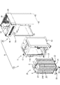
本発明の実施形態1を図1から図4によって説明する。本実施形態では、調理機器として、冷温蔵装置9を例示する。冷温蔵装置9は、図1に示すように、トレイXを収納するカート10と、同カート10を出し入れ可能に格納するステーション30と、を備えている。なお、このような冷温蔵装置9は再加熱カートと呼ばれる。カート10は、断熱箱からなるカート本体11と、トレイXを収納するフレームカート20とから構成されている。カート本体11は前後両面が開口され、その開口部11Aにはそれぞれ観音開き式の断熱扉12が装着されている。また、カート本体11の底面にはキャスタ13が設けられている。
<Embodiment 1>
A first embodiment of the present invention will be described with reference to FIGS. In this embodiment, the
フレームカート20は、キャスタ22を設けた底板21の左右の側縁から金属製のフレーム23が立ち上げられた構造であって、上記したカート本体11内に前面側から出し入れ可能となっている。フレームカート20の左右方向の略中央部分には、前後方向全域に亘って仕切壁24が設けられている。仕切壁24は断熱性の高い複数の単位仕切壁24Aを積み上げた形状であって、トレイXは、前後両面から、上下の単位仕切壁24Aの間を貫通しつつ複数段に亘って収納されるようになっている。フレームカート20がカート本体11内に収納した状態では、図2に示すように、カート本体11の内部が仕切壁24によって左右に仕切られ、例えば、仕切壁24の左側に温蔵室25Hが、右側に冷蔵室25Cが形成されるようになっている。
The
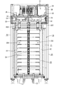
ステーション30は、正面が開口された略箱形をなし、その開口を通してカート10が出し入れ可能となっている。図2に示すように、ステーション30の天井部には、第1熱交換室31と第2熱交換室32とが左右に並んで区画形成され、温蔵室25Hの上方に配される左側の第1熱交換室31には、冷却部である冷却器33、加熱部であるヒータ34が設けられている。一方、冷蔵室25Cの上方に配される右側の第2熱交換室32には、冷却部である冷却器33のみが設けられている。両熱交換室31,32には循環ファン35がそれぞれ設けられている。両冷却器33は、ステーション30の機械室36に装備された圧縮機38等を含む冷凍装置37と並列接続されている。
The
カート10がステーション30内に格納された状態では、第1熱交換室31と温蔵室25Hの間において空気を循環可能とする第1空気循環路41が形成され、第2熱交換室32と冷蔵室25Cの間において空気を循環可能とする第2空気循環路42が形成される。第1空気循環路41によって、温蔵室25Hの天井側から温蔵室25H内の空気を引いて第1熱交換室31に送り、この空気を熱交換した後、温蔵室25Hの側面から温蔵室25H内に送ることが可能となっている。また、第2空気循環路42によって、冷蔵室25Cの天井側から冷蔵室25C内の空気を引いて第2熱交換室32に送り、この空気を熱交換した後、冷蔵室25Cの側面から冷蔵室25C内に送ることが可能となっている。
In the state where the
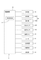
次に、冷温蔵装置9の電気的構成について説明する。図3に示すように、冷温蔵装置9は、制御部50を備えている。制御部50には、記憶部56、表示部54A、操作部54B、温度センサ43H、温度センサ43C、2つの循環ファン35、ヒータ34、冷凍装置37(より具体的には圧縮機38など)、内蔵時計57、通信部59が電気的に接続されている。制御部50は、例えば、CPUを主体に構成されており、記憶部56は、例えば、ROMやRAMなどによって構成されている。制御部50は、記憶部56に記憶されたコンピュータプログラムを実行することで、制御部50に接続された各機器を制御することが可能となっている。なお、制御部50は、例えば、機械室36内に配置された電装箱26(図1参照)内に収容されているが、これに限定されない。
Next, an electrical configuration of the
また、表示部54A及び操作部54Bは、図1に示すタッチパネル54によって構成されている。作業者は、タッチパネル54に表示されるスイッチを操作することで、冷温蔵装置9の運転や各種設定を行うことができる。通信部59は、他の冷温蔵装置9との通信を行うためのハードウェアインタフェースであり、通信ネットワークを介して他の冷温蔵装置9と接続される。内蔵時計57は、時刻を計時するものとされる。また、制御部50は、内蔵時計57の時刻設定(詳しくは後述)に係る処理を行う時刻設定部51を備えており、記憶部56には、時刻設定部51が処理を実行するためのコンピュータプログラムが記憶されている。
The
次に、本実施形態の冷温蔵装置9の使用形態の一例を説明する。まず、調理等の準備をした温食と冷食とをトレイXに分けて盛り付けて、各トレイXをフレームカート20に収納し、フレームカート20をカート本体11に収納してカート10を構成する(盛付け工程)。次にカート10がステーション30内に入れられ、運転スイッチがオンされると、冷蔵モードが実行される。
Next, an example of the usage pattern of the
冷蔵モードでは、両熱交換室31,32において冷却器33が作動状態とされ、温蔵室25Hと冷蔵室25Cには共に冷気が循環供給されることで、トレイXに載せられた温食と冷食が共に冷蔵保存(チルド保存)される。この冷蔵モードでは、温蔵室25H及び冷蔵室25Cの各庫内温度が各温度センサ43H,43Cで検知される。各温度センサ43H,43Cによって検知された温度は、設定温度と比較され、その比較結果に基づいて、制御部50が冷凍装置37の開閉弁の開閉切替や、圧縮機38のオンオフ切替を行うことで、各室25H,25Cに対応した各熱交換室31,32の冷却器33の作動、又は非作動が制御され、温蔵室25Hと冷蔵室25Cの庫内温度がほぼ設定温度に維持されるようになっている。
In the refrigeration mode, the cooler 33 is activated in both the
そして、冷温蔵装置9に内蔵された内蔵時計57の現在時刻が、予め設定された所定時刻となったら、再加熱モードに切り替わる。なお、このような所定時刻は、例えば、食品を配膳する配膳時刻から加熱時間などを逆算することで決定される。再加熱モードにおいては、第1熱交換室31では、冷却器33が非作動とされ、ヒータ34の作動に切り替わる一方、第2熱交換室32では、引き続き冷却器33が作動された状態が維持される。これにより、温蔵室25H内には暖気が循環されて温食が再加熱される一方、冷蔵室25Cには引き続き冷気が循環供給されてチルド保存される。
Then, when the current time of the built-in
所定時間が経過して配膳時刻となったら、再加熱モードが終了し、併せて運転スイッチがオフとなる。その後、カート10がステーション30から引き出され、トレイXが取り出されて配膳に供されるようになっている。なお、配膳が終了すると、フレームカート20のみが配膳場所に残され、下膳時に用いられる。上述したように、冷温蔵装置9においては、内蔵時計57によって計時された現在時刻に基づいて制御を行う。このため、内蔵時計57の現在時刻を定期的に正しい時刻に設定することが求められる。
When the predetermined time elapses and the serving time is reached, the reheating mode is finished and the operation switch is turned off. Thereafter, the
次に、内蔵時計57の時刻設定について説明する。本実施形態では、1日のうち予め設定された設定時刻を基準として内蔵時計57の時刻設定を行う構成となっている。つまり、本実施形態では、1日に1回の時刻設定を毎日行う。なお、設定時刻としては、冷温蔵装置9を動作させる機会が少ない時間帯で設定することが好ましく、例えば、深夜帯で設定することが好ましい。
Next, the time setting of the built-in
まず、時刻設定に用いるパラメータである補正値について説明する。本実施形態では、補正値は、1日に生じる内蔵時計57の誤差に相当する値である。なお、内蔵時計57の誤差は、内蔵時計57を構成する部品の精度や経年劣化、及び設置環境(温度など)に起因して生じる。作業者は、例えば、次の(1)式によって補正値を算出する。
First, correction values that are parameters used for time setting will be described. In the present embodiment, the correction value is a value corresponding to an error of the
補正値=(所定日数N1経過後の内蔵時計57の誤差E1)/(所定日数N1)・・・(1)
Correction value = (error E1 of
上記誤差E1は、例えば、タッチパネル54を用いて作業者が内蔵時計57を正確な時刻に設定した後、所定日数N1だけ経過させ、その後、実際の時刻(例えば時報や電波時計などによって求めた正確な時刻)と、内蔵時計57が示す現在時刻との差を求めることで算出することができる。なお、所定日数N1は例えば30日(一か月)で設定されるが、これに限定されない。また、以下の説明では、内蔵時計57の時刻が実際の時刻より遅れている場合には、補正値を正の値とし、内蔵時計57の時刻が実際の時刻より進んでいる場合には、補正値を負の値として説明する。例えば、30日で内蔵時計57が180秒遅れる場合、E1=180、N1=30であるから、補正値は「6(秒/日)」である。
The error E1 is, for example, the time set by the operator using the
設定時刻及び補正値は、作業者がタッチパネル54(操作部54B)を操作することで設定することができ、設定された設定時刻及び補正値は、記憶部56に記憶されている。また、記憶部56において、記憶容量の制約などから、符号のない変数として補正値を扱う必要がある場合には、負の補正値については、変数の使用領域のうち、正の補正値に割り当てられている領域外の数に変換して処理を行えばよい。なお、本実施形態では、設定時刻は、例えば、時間単位及び分単位で設定することができる。
The set time and the correction value can be set by the operator operating the touch panel 54 (
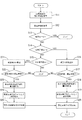
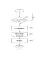
次に、時刻設定部51における時刻設定の処理について、図4のフローチャートを用いて説明を行う。図4に示すように、冷温蔵装置9の電源がオンされると、時刻設定部51は、内蔵時計57の現在時刻を取得し(ステップS11)、記憶部56に記憶されている設定時刻を取得する(ステップS12)。次に、時刻設定部51は、記憶部56に記憶されている補正値を参照し、補正値が0以外である場合(ステップS13が「NO」)には、補正値が、設定可能範囲内の値であるか否かを判断すると共に、正の値であるか負の値であるかを判断する(ステップS14及びステップS15)。また、補正値が0である場合(ステップS13が「YES」)には、ステップS11の処理に戻る。
Next, the time setting process in the
なお、補正値の設定可能範囲は、内蔵時計57に生じ得る誤差に基づいて設定される。例えば、内蔵時計57の誤差が、30日で−380秒〜+90秒の範囲で起こり得る場合には、1日に最大で12.6秒の誤差が想定される。この場合、補正値の設定可能範囲は、例えば、−13秒〜+13秒で設定される。なお、上述の誤差範囲の場合、内蔵時計57の30日の誤差の上限は90秒であるため、補正値の設定可能範囲の上限を例えば+3秒(=90/30)としてもよい。
The settable range of the correction value is set based on an error that may occur in the built-in
補正値が正の値である場合(ステップS14が「YES」)には、時刻設定部51は、設定時刻に補正値を減算することで、補正時刻を算出する(ステップS16、補正時刻算出処理)。例えば、設定時刻が「1時35分00秒」であり、補正値が「6秒」である場合には、補正時刻は「1時34分54秒」となる。続いて、内蔵時計57の現在時刻が補正時刻になる(ステップS17が「YES」)と、時刻設定部51は、記憶部56に記憶されている内蔵時計57の現在時刻を設定時刻に書き換える(ステップS18)。なお、記憶部56は、例えば、時刻設定に用いるメモリ領域(第1メモリ)と、内蔵時計57が現在時刻として参照する数値が記憶されるメモリ領域(第2メモリ)とを備えている。ステップS18では、例えば、第1メモリに記憶されている現在時刻の値を設定時刻の値に書き換える処理を行う。
When the correction value is a positive value (“YES” in step S14), the
続いて、時刻設定部51は、記憶部56に記憶されている設定反映フラグをオン(設定反映フラグ=1)にして、第1メモリに書き込まれた設定時刻を第2メモリに書き込む処理を行う。これにより、内蔵時計57の時刻設定が反映される(ステップS19)。これ以降、内蔵時計57は、記憶部56(第2メモリ)に書き込まれた設定時刻を基準として計時を行う。つまり、ステップS18及びS19は、内蔵時計57の現在時刻を設定時刻に変更する時刻変更処理の一例である。
Subsequently, the
次に、時刻設定部51は、所定時間待機した後、設定反映フラグを反転させることでオフ(設定反映フラグ=0)にする(ステップS20)。これにより、次回の時刻設定が可能な状態となる。なお、ステップS20の処理は、所定の条件(例えば設定可能範囲外の時刻が入力される等)を満たすことで設定反映フラグを反転させるプログラムを用いて行ってもよい。
Next, after waiting for a predetermined time, the
ここで、ステップS16〜S19の処理について、具体的な数値を例示して説明する。例えば、補正値が「6秒」である場合には、内蔵時計57は、実際の時刻よりも「6秒」遅れていることになる。補正値が「6秒」で、設定時刻が「1時35分00秒」である場合には、補正時刻は「1時34分54秒」となる。このため、内蔵時計57の現在時刻が「1時34分54秒」になると、時刻設定部51は、内蔵時計57の現在時刻を「1時34分54秒」から「1時35分00秒」に変更する処理を行う。これにより、内蔵時計57の「6秒」の遅れが補正され、内蔵時計57の現在時刻が正確な時刻となる。
Here, the processing of steps S16 to S19 will be described by exemplifying specific numerical values. For example, when the correction value is “6 seconds”, the built-in
また、補正値が負の値、且つ設定可能範囲内の値である場合(ステップS15が「YES」)には、時刻設定部51は、設定時刻に補正値の絶対値を加算することで、補正時刻を算出する(ステップS21、補正時刻算出処理)。例えば、設定時刻が「1時35分00秒」であり、補正値が「−4秒」である場合には、補正時刻は「1時35分04秒」となる。続いて、内蔵時計57の現在時刻が補正時刻になる(ステップS22が「YES」)と、時刻設定部51は、記憶部56の第1メモリに記憶されている内蔵時計57の現在時刻を設定時刻に書き換える(ステップS23)。
In addition, when the correction value is a negative value and a value within the settable range (step S15 is “YES”), the
続いて、時刻設定部51は、設定反映フラグをオン(設定反映フラグ=1)にして、第1メモリに書き込まれた設定時刻を第2メモリに書き込む処理を行う。これにより、内蔵時計57の時刻設定が反映される(ステップS24)。これ以降、内蔵時計57は、記憶部56に書き込まれた設定時刻を基準として計時を行う。つまり、ステップS23及びS24は、内蔵時計57の現在時刻を設定時刻に変更する時刻変更処理の一例である。
Subsequently, the
続いて、時刻設定部51は、所定の待機時間だけ待機し(ステップS25)、その後、設定反映フラグをオフ(設定反映フラグ=0)にする(ステップS20)。これにより、次回の時刻設定が可能な状態となる。
Subsequently, the
ここで、ステップS21〜S24の処理について、具体的な数値を例示して説明する。例えば、補正値が「−4秒」である場合には、内蔵時計57は、実際の時刻よりも「4秒」進んでいることになる。補正値が「−4秒」で、設定時刻が「1時35分00秒」である場合には、補正時刻は「1時35分04秒」となる。このため、内蔵時計57の現在時刻が「1時35分04秒」になると、時刻設定部51は、内蔵時計57の現在時刻を「1時35分04秒」から「1時35分00秒」に変更する処理を行う。これにより、「4秒」の進みが補正され、内蔵時計57の現在時刻が正確な時刻となる。
Here, the processing of steps S21 to S24 will be described by exemplifying specific numerical values. For example, when the correction value is “−4 seconds”, the built-in
なお、補正値が負の値である場合には、ステップS23,S24の処理によって、内蔵時計57の現在時刻が補正値の秒数だけ遡ることになる。このため、ステップS25において、所定の待機時間だけ待機させた後、次の処理(ひいては次回のステップS11の処理)に移るようにしている。この待機時間は、補正値の設定可能範囲の下限値(本実施形態では、−13秒)の絶対値よりも大きい値(例えば30秒)で設定される。これにより、S22〜24の処理が同じ現在時刻(例えば「1時35分04秒」)で、繰り返し行われる事態を防止することができる。
If the correction value is a negative value, the current time of the built-in
なお、本実施形態において、内蔵時計57の現在時刻を設定時刻に書き換える処理は、例えば、次のように行う。例えば、現在時刻(=補正時刻)が「1時34分54秒」で、設定時刻が「1時35分」である場合には、現在時刻に6秒を加算するのではなく、現在時刻に1分を加算すると共に、現在時刻の秒(54秒)を0秒にリセットする処理を行う。また、例えば、現在時刻が「1時35分4秒」で、設定時刻が「1時35分」である場合には、現在時刻の秒(4秒)を0秒にリセットする処理を行う。このようにすれば、時刻を秒単位で加減算するためのプログラムを実装することなく、秒単位の補正を行うことができる。
In the present embodiment, the process of rewriting the current time of the built-in
次に、本実施形態の効果について説明する。本実施形態によれば、補正値に基づいて算出された補正時刻になった時点で、内蔵時計57の現在時刻が設定時刻に変更される。これにより、内蔵時計57の現在時刻は、補正値の分だけ補正される。このように、本実施形態では、内蔵時計57の時刻設定(時刻補正)を一日一回確実に行うことができ、内蔵時計57の誤差を小さくすることができる。言い換えると、作業者が行う時刻設定の頻度を少なくすることができる。なお、本実施形態では、補正値の単位を秒単位で設定可能な構成となっており、内蔵時計57の誤差を1秒単位で補正することができる。つまり、一日で生じる内蔵時計57の誤差を、±1秒未満に抑えることができるので、30日間で生じる誤差を±30秒未満に抑えることができる。
Next, the effect of this embodiment will be described. According to the present embodiment, when the correction time calculated based on the correction value is reached, the current time of the built-in
また、本実施形態では、所定期間に生じる内蔵時計57の誤差を所定期間で割った値を補正値とし、一日毎にその補正値だけ補正を行う。このようにすれば、所定期間(例えば一か月)毎に内蔵時計57の補正を行う構成と比べて、一回の補正量が少なくて済む。このため、冷温蔵装置9を使用する使用者は、内蔵時計57の時刻が補正されたことを認識し難い。この結果、使用者は違和感なく、冷温蔵装置9を使用することができる。また、使用者が手動で内蔵時計57の時刻補正を行う場合には、補正の作業を忘れてしまう事態も懸念されるが、本実施形態では、自動的に補正が行われるので、このような事態を防止することができる。
In the present embodiment, a value obtained by dividing the error of the
<実施形態2>
次に、本発明の実施形態2を図5及び図6によって説明する。本実施形態では、時刻設定部51が補正値を用いて内蔵時計57の時刻設定を行う点については、上記実施形態と同一であるが、補正値を算出する処理を行う点が相違する。なお、上記実施形態と同一部分には、同一符号を付して重複する説明を省略する。上記実施形態で説明したように、冷温蔵装置9においては、作業者は、タッチパネル54に表示されるスイッチを操作することで、冷温蔵装置9の各種設定を行うことができる。
<Embodiment 2>
Next, a second embodiment of the present invention will be described with reference to FIGS. This embodiment is the same as the above embodiment in that the
各種設定の一つとして、作業者は、タッチパネル54(操作部54B、入力部の一例)を操作することで、例えば時報などで求めた正確な時刻(例えば時間及び分)を入力し、内蔵時計57の現在時刻を変更することができる。なお、以下の説明では、内蔵時計57の現在時刻をタッチパネル54によって入力された時刻に変更することを手動時刻設定と呼び、上記実施形態で説明した補正値を用いた時刻設定(自動時刻設定)と区別するものとする。
As one of various settings, the operator operates the touch panel 54 (an
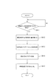
本実施形態では、作業者によって入力された時刻及び内蔵時計57の現在時刻を利用して、補正値を算出する処理を行う構成となっている。次に、作業者によって時刻が入力された際の時刻設定部51の処理について、図5のフローチャートを用いて説明を行う。図5に示すように、タッチパネル54によって時刻が入力される(ステップS111が「YES」)と、時刻設定部51は、入力された時刻(以下、入力時刻)と、その時点の内蔵時計57の現在時刻を記憶部56に記憶する(ステップS112)。なお、入力時刻には、例えば、時分に係る情報が含まれており、内蔵時計57の現在時刻には、例えば、年月日及び時分秒に係る情報が含まれているが、これに限定されない。
In the present embodiment, the correction value is calculated using the time input by the operator and the current time of the built-in
次に、時刻設定部51は、内蔵時計57の現在時刻を入力時刻に変更する(ステップS113、入力時刻変更処理)。より具体的には、現在時刻の時分を入力時刻の時分に変更する。これにより、手動時刻設定が完了する。なお、内蔵時計57の誤差は時間が経過すると累積されて大きくなっていくことが一般的であるから、作業者は、手動時刻設定を定期的に行うことが好ましい。時刻設定部51は、手動時刻設定が行われる毎に、入力された入力時刻と、その入力時刻が入力された時点の内蔵時計57の現在時刻とを対応付けて記憶部56に記憶する。
Next, the
次に、手動時刻設定の際に記憶した入力時刻及び現在時刻を用いた補正値の算出処理について、図6のフローチャートを用いて説明を行う。図6に示すように、2回目以降の手動時刻設定が完了すると(ステップS211が「YES」)、時刻設定部51は、前回の手動時刻設定時において記憶された内蔵時計57の現在時刻D1を取得する(ステップS212)。より詳しくは、現在時刻D1(第1現在時刻)は、「前回の入力時刻変更処理における入力時刻(第1入力時刻)が入力された時点の内蔵時計57の現在時刻」である。
Next, correction value calculation processing using the input time and the current time stored at the time of manual time setting will be described with reference to the flowchart of FIG. As shown in FIG. 6, when the second and subsequent manual time settings are completed (step S211 is “YES”), the
また、時刻設定部51は、今回行われた(より正確には直前に行われた)手動時刻設定において記憶された入力時刻H2及び内蔵時計57の現在時刻D2を取得する(ステップS213)。つまり、入力時刻H2(第2入力時刻)は、今回の入力時刻変更処理においてタッチパネル54によって入力された入力時刻であり、現在時刻D2(第2現在時刻)は、入力時刻H2が入力された時点の内蔵時計57の現在時刻である。なお、現在時刻D2は、入力時刻H2に変更される前の現在時刻である。
In addition, the
続いて、時刻設定部51は、以下の(2)式によって補正値を算出する(ステップS214、補正値算出処理)。算出された補正値は、記憶部56に記憶され、補正値を用いた時刻設定の際に用いられる。
補正値=(H2−D2B)/(D2A−D1A)・・・(2)
Subsequently, the
Correction value = (H2-D2B) / (D2A-D1A) (2)
ここで、(2)式におけるD1Aは、現在時刻D1のうち年月日に係る値である。また、D2Aは、現在時刻D2のうち年月日に係る値である。つまり、(2)式の(D2A−D1A)は、前回手動時刻設定を行ってからの期間(日数)である。なお、(D2A−D1A)は、「第2現在時刻と第1現在時刻の差」の一例である。そして、D2Bは、現在時刻D2のうち、時分に係る値である。 Here, D1A in the equation (2) is a value related to the date of the current time D1. D2A is a value related to the date of the current time D2. That is, (D2A-D1A) in equation (2) is the period (number of days) since the previous manual time setting. (D2A−D1A) is an example of “difference between the second current time and the first current time”. D2B is a value related to the hour and minute in the current time D2.
ここで、作業者によって入力された入力時刻H1,H2は、実際の時刻に基づいた正確な時刻と考えることができる。そして、内蔵時計57の現在時刻は、前回の手動時刻設定において、正しい時刻(入力時刻H1)に補正されている。このため、(2)式の(H2−D2B)は、実際の時刻と内蔵時計57の現在時刻との差である。言い換えると(H2−D2B)は、前回手動時刻設定を行ってから(D2A−D1A)の期間に生じた内蔵時計57の誤差である。なお、(H2−D2B)は、「第2入力時刻と第2現在時刻の差」の一例である。
Here, the input times H1 and H2 input by the operator can be considered as accurate times based on the actual time. The current time of the built-in
また、本実施形態では、補正値は「1日に生じる内蔵時計57の誤差に相当する値」として設定され、その単位は、例えば(秒/日)である。このため、時刻設定部51では、年月日に係る情報である「D2A−D1A」を「日数」に変換し、時分に係る情報である「H2−D2B」を「秒」に変換して、補正値を算出する。なお、補正値の単位は、(秒/日)に限定されず適宜変更可能であるが、一般的に一日で生じる内蔵時計57の誤差は秒単位であることが多いから、秒を基準として補正値を設定することが好ましい。
In the present embodiment, the correction value is set as “a value corresponding to the error of the built-in
ここで、ステップS214の補正値算出処理について以下の具体的な数値を例示して説明する。
現在時刻D1=「2015年12月1日8時14分00秒」
D1A=「2015年12月1日」
現在時刻D2=「2015年12月31日13時07分00秒」
D2A=「2015年12月31日」
D2B=「13時07分」
入力時刻H2=「13時10分」
上述した値の時、(H2−D2B)=3分=180秒であり、(D2A−D1A)=30日となる。このため、補正値(秒/日)=180/30=6と算出される。
Here, the correction value calculation processing in step S214 will be described with reference to the following specific numerical values.
Current time D1 = “December 1, 2015 8:14:00”
D1A = “December 1, 2015”
Current time D2 = “December 31, 2015 13:07:00”
D2A = “December 31, 2015”
D2B = "13:07"
Input time H2 = "13:10"
At the above-described value, (H2-D2B) = 3 minutes = 180 seconds, and (D2A-D1A) = 30 days. Therefore, the correction value (second / day) = 180/30 = 6 is calculated.
本実施形態によれば、タッチパネル54によって入力された時刻に基づいて内蔵時計57の時刻を変更することができる。これにより、冷温蔵装置9の作業者は、タッチパネル54を用いて正確な時刻を入力することで、内蔵時計57の現在時刻を正しい時刻に補正することができる。そして、本実施形態では、作業者が手動時刻設定を少なくとも2回(前回及び今回)行うことで、制御部50は、内蔵時計57の誤差(式2のH2−D2B)と、経過期間(式2のD2A−D1A)に基づいて、補正値を算出することができる。このような構成とすれば、作業者が補正値を算出して入力する必要がなく、好適である。
According to the present embodiment, the time of the built-in
<実施形態3>
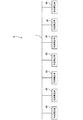
次に、本発明の実施形態3を図7から図9によって説明する。本実施形態では、図7に示すように、複数台の冷温蔵装置9(図7において符号9A〜9Nを付す)によって、冷温蔵装置システム5が構成されている。各冷温蔵装置9は、プロトコル変換装置(図示せず)及び、各冷温蔵装置9が備える通信部59(図3参照)を介してLAN(Local Area Network)などの通信ネットワーク7に接続されている。各冷温蔵装置9は通信ネットワーク7を介して、互いに通信を行うことが可能な構成となっている。通信部59は、他の冷温蔵装置9とのデータの送受信を制御することが可能な構成となっており、通信ネットワーク7としてLANを用いる場合、例えば、LANコントローラなどによって構成されている。また、通信ネットワーク7は、LANに限定されず適宜変更可能である。
<Embodiment 3>
Next, a third embodiment of the present invention will be described with reference to FIGS. In the present embodiment, as shown in FIG. 7, a refrigeration /
本実施形態では、複数の冷温蔵装置9のうち、親機として設定された冷温蔵装置9(以下、符号9A)からのデータ配信によって、子機として設定された他の冷温蔵装置9(以下、符号9B〜9N、他の調理機器)の時刻設定を一括して行うことが可能な構成となっている。まず、親機として設定された冷温蔵装置9Aにおける処理について、図8のフローチャートを用いて説明を行う。図8に示すように、冷温蔵装置9Aの制御部50は、冷温蔵装置9Aの内蔵時計57の現在時刻を取得し(ステップS311)、この現在時刻と記憶部56に記憶されている配信時刻とが一致するか否かを判定する(ステップS312)。
In the present embodiment, among the plurality of refrigeration /
この配信時刻は、親機から子機へのデータ配信が行われる時刻であり、タッチパネル54などによって入力することで適宜設定可能である。なお、配信時刻は、冷温蔵装置9を動作する機会が少ない時間帯で設定することが好ましく、例えば、深夜帯で設定することが好ましい。また補正値による内蔵時計57の時刻設定(上記実施形態1参照)を行った直後であれば、内蔵時計57の時刻の誤差は比較的少ない。このため、配信時刻は、設定時刻よりも少し後の時刻で設定することが好ましい。例えば、補正値による時刻設定の設定時刻が「1時35分00秒」である場合、配信時刻をそれ以降に設定することが好ましく、例えば「2時00分00秒」で設定される。そして、この配信時刻は、冷温蔵装置システム5を構成する冷温蔵装置9A〜9Nの記憶部56に共通の値が記憶されている。
This distribution time is a time at which data distribution from the parent device to the child device is performed, and can be appropriately set by inputting through the
図8に示すように、現在時刻が配信時刻と一致する場合(ステップS312が「YES」)には、制御部50は、通信部59(図3参照)を介して、子機である他の冷温蔵装置9B〜9Nに一括して時刻設定フラグ(時刻設定フラグ=1)を配信する(ステップS313、配信処理)。この時刻設定フラグは、親機が配信時刻になったことを子機に伝える情報である。
As shown in FIG. 8, when the current time coincides with the distribution time (“YES” in step S312), the
次に、子機として設定された冷温蔵装置9B〜9Nにおける処理について、図9のフローチャートを用いて説明を行う。なお、以下の説明では、冷温蔵装置9B〜9Nのうち、例えば冷温蔵装置9Bにおける処理を例示するが、冷温蔵装置9C〜9Nについても同じ処理が実行される。図9に示すように、冷温蔵装置9Bの制御部50(時刻設定部51)は、冷温蔵装置9Aから配信された時刻設定フラグを受信する(ステップS411が「YES」)と、冷温蔵装置9Bの内蔵時計57(他の調理機器の第1内蔵時計)の現在時刻を記憶部56に記憶されている配信時刻(例えば2時00分00秒)に書き換える(ステップS412)。つまり、時刻設定フラグは、親機(冷温蔵装置9A)から、子機(冷温蔵装置9B〜9N)に配信される「第1内蔵時計の時刻設定に係る情報」の一例である。
Next, processing in the
続いて、制御部50は、記憶部56に記憶されている設定反映フラグをオン(設定反映フラグ=1)にすることで内蔵時計57の時刻設定を反映させる(ステップS413)。つまり、ステップS412及びS413は、内蔵時計57の現在時刻を配信時刻に変更する変更処理である。その後、制御部50は、設定反映フラグを反転させることでオフ(設定反映フラグ=0)にし(ステップS414)、次回の時刻設定を可能な状態とした後、時刻設定フラグを取り消す(時刻設定フラグ=0、ステップS415)。
Subsequently, the
本実施形態によれば、親機である冷温蔵装置9Aが配信時刻になった時点で子機である冷温蔵装置9B〜9Nの内蔵時計57の現在時刻が配信時刻に変更される。これにより、冷温蔵装置9A〜9Nの現在時刻を同期させることができる。そして、本実施形態の冷温蔵装置9Aは、上記実施形態で説明したように、補正値を用いることで内蔵時計57の時刻補正を定期的に行うことができるから、より正確な時刻に他の冷温蔵装置9B〜9Nに時刻設定に係る情報を配信することができる。このため、他の冷温蔵装置9B〜9Nにおいても、より正確な時刻で動作を行うことができる。なお、本実施形態では、冷温蔵装置9Aから冷温蔵装置9B〜9Nに対して、時刻設定フラグを配信する構成を例示したが、これに限定されない。例えば、冷温蔵装置9Aから冷温蔵装置9B〜9Nに対して配信時刻(時刻の数値情報)を配信する構成としてもよい。しかしながら、時刻設定フラグを配信する構成とすれば、通信に係るデータ量をより少なくすることができ、好適である。
According to the present embodiment, the current time of the built-in
<他の実施形態>
本発明は上記記述及び図面によって説明した実施形態に限定されるものではなく、例えば次のような実施形態も本発明の技術的範囲に含まれる。
(1)上記実施形態では、内蔵時計を備える調理機器として冷温蔵装置9を例示したが、これに限定されない。調理機器としては、内蔵時計の時刻に基づいて動作するものを例示することができ、例えば、オーブン、炊飯器、冷蔵庫などを例示することができる。
(2)上記実施形態では、入力部として、タッチパネル54を例示したが、これに限定されない。入力部は、時刻を入力可能な構成のものであればよく、機械式の入力ボタンなどを例示することも可能である。また、通信部59を介して制御部50と接続可能なコンピュータを備えていてもよく、そのコンピュータから時刻を入力する構成としてもよい。つまり、コンピュータを入力部として用いてもよい。
(3)上記実施形態では、補正値を1日で生じる内蔵時計57の誤差とし、1日1回補正値を用いて内蔵時計57の時刻補正を行う構成を例示したが、補正を行う頻度は、これに限定されない。例えば、2日に1回補正値を用いて内蔵時計57の時刻補正を行ってもよく、その場合には、補正値を2日で生じる内蔵時計57の誤差として設定すればよい。
<Other embodiments>
The present invention is not limited to the embodiments described with reference to the above description and drawings. For example, the following embodiments are also included in the technical scope of the present invention.
(1) In the above embodiment, the
(2) In the above embodiment, the
(3) In the above embodiment, the configuration in which the correction value is an error of the
9…冷温蔵装置(調理機器)、9B…冷温蔵装置(他の調理機器)、50…制御部、54…タッチパネル(入力部)、56…記憶部、57…内蔵時計(内蔵時計、又は他の調理機器が備える第1内蔵時計)、59…通信部、D1…現在時刻(第1現在時刻)、D2…現在時刻(第2現在時刻)、H2…入力時刻(第2入力時刻)
DESCRIPTION OF
Claims (3)
前記内蔵時計の時刻設定を行うことが可能な制御部を備え、
前記制御部は、
予め設定された設定時刻に対して、前記内蔵時計の誤差に基づいて設定された補正値を加算又は減算することで、補正時刻を算出する補正時刻算出処理と、
前記内蔵時計の現在時刻が前記補正時刻となった時点で前記内蔵時計の現在時刻を前記設定時刻に変更する時刻変更処理と、を実行する調理機器。 A cooking device with a built-in clock,
A control unit capable of setting the time of the built-in clock;
The controller is
A correction time calculation process for calculating a correction time by adding or subtracting a correction value set based on an error of the built-in clock with respect to a preset setting time;
A cooking device that performs a time change process of changing the current time of the internal clock to the set time when the current time of the internal clock becomes the correction time.
前記入力部によって入力された時刻である入力時刻と、前記入力時刻が入力された時点の前記内蔵時計の現在時刻と、をそれぞれ記憶する記憶部と、を備え、
前記制御部は、
前記入力時刻に基づいて前記内蔵時計の現在時刻を変更する入力時刻変更処理を実行するものとされ、
前回の前記入力時刻変更処理において前記入力部によって入力された前記入力時刻を第1入力時刻とし、
今回の前記入力時刻変更処理において前記入力部によって入力された前記入力時刻を第2入力時刻とし、
前記第1入力時刻が入力された時点の前記内蔵時計の現在時刻を第1現在時刻とし、
前記第2入力時刻が入力された時点の前記内蔵時計の現在時刻を第2現在時刻とした場合において、
さらに、前記制御部は、前記今回の前記入力時刻変更処理の後に、
前記第2入力時刻と前記第2現在時刻の差、及び前記第2現在時刻と前記第1現在時刻の差に基づいて、前記補正値を算出する補正値算出処理を実行する請求項1に記載の調理機器。 An input unit capable of inputting time; and
A storage unit that stores an input time that is a time input by the input unit and a current time of the built-in clock at the time when the input time is input;
The controller is
An input time changing process for changing the current time of the internal clock based on the input time is executed,
The input time input by the input unit in the previous input time change process is the first input time,
The input time input by the input unit in the current input time change process is the second input time,
The current time of the built-in clock at the time when the first input time is input is defined as a first current time,
When the current time of the internal clock at the time when the second input time is input is the second current time,
Further, the control unit, after the current input time change process,
The correction value calculation process for calculating the correction value is executed based on a difference between the second input time and the second current time and a difference between the second current time and the first current time. Cooking equipment.
前記制御部は、
前記内蔵時計の現在時刻が予め設定された配信時刻となった時点で、前記通信部を介して、前記他の調理機器に前記第1内蔵時計の時刻設定に係る情報を配信する配信処理を行う請求項1又は請求項2に記載の調理機器。 A communication unit capable of communicating with other cooking appliances including the first built-in clock;
The controller is
When the current time of the built-in clock becomes a preset delivery time, a delivery process is performed for delivering information relating to the time setting of the first built-in clock to the other cooking appliance via the communication unit. The cooking appliance according to claim 1 or claim 2.
Priority Applications (1)
| Application Number | Priority Date | Filing Date | Title |
|---|---|---|---|
| JP2016016902A JP6815081B2 (en) | 2016-02-01 | 2016-02-01 | Cooking equipment |
Applications Claiming Priority (1)
| Application Number | Priority Date | Filing Date | Title |
|---|---|---|---|
| JP2016016902A JP6815081B2 (en) | 2016-02-01 | 2016-02-01 | Cooking equipment |
Publications (2)
| Publication Number | Publication Date |
|---|---|
| JP2017136102A true JP2017136102A (en) | 2017-08-10 |
| JP6815081B2 JP6815081B2 (en) | 2021-01-20 |
Family
ID=59564428
Family Applications (1)
| Application Number | Title | Priority Date | Filing Date |
|---|---|---|---|
| JP2016016902A Active JP6815081B2 (en) | 2016-02-01 | 2016-02-01 | Cooking equipment |
Country Status (1)
| Country | Link |
|---|---|
| JP (1) | JP6815081B2 (en) |
Citations (6)
| Publication number | Priority date | Publication date | Assignee | Title |
|---|---|---|---|---|
| JPS56116199A (en) * | 1980-02-18 | 1981-09-11 | Mitsubishi Electric Corp | Remoteecontrolling controller |
| JP2002008079A (en) * | 2000-06-19 | 2002-01-11 | Max Co Ltd | Time recorder |
| JP2003167079A (en) * | 2001-11-30 | 2003-06-13 | Rhythm Watch Co Ltd | Automatic correcting clock |
| JP2003240884A (en) * | 2002-02-21 | 2003-08-27 | Nec Access Technica Ltd | Electronic clock device, time correction method and time correction program for electronic clock device |
| JP2005067171A (en) * | 2003-08-28 | 2005-03-17 | Sato Corp | Electronics |
| JP2011043310A (en) * | 2009-08-24 | 2011-03-03 | Hoshizaki Electric Co Ltd | Cold and hot storage device for food |
-
2016
- 2016-02-01 JP JP2016016902A patent/JP6815081B2/en active Active
Patent Citations (6)
| Publication number | Priority date | Publication date | Assignee | Title |
|---|---|---|---|---|
| JPS56116199A (en) * | 1980-02-18 | 1981-09-11 | Mitsubishi Electric Corp | Remoteecontrolling controller |
| JP2002008079A (en) * | 2000-06-19 | 2002-01-11 | Max Co Ltd | Time recorder |
| JP2003167079A (en) * | 2001-11-30 | 2003-06-13 | Rhythm Watch Co Ltd | Automatic correcting clock |
| JP2003240884A (en) * | 2002-02-21 | 2003-08-27 | Nec Access Technica Ltd | Electronic clock device, time correction method and time correction program for electronic clock device |
| JP2005067171A (en) * | 2003-08-28 | 2005-03-17 | Sato Corp | Electronics |
| JP2011043310A (en) * | 2009-08-24 | 2011-03-03 | Hoshizaki Electric Co Ltd | Cold and hot storage device for food |
Also Published As
| Publication number | Publication date |
|---|---|
| JP6815081B2 (en) | 2021-01-20 |
Similar Documents
| Publication | Publication Date | Title |
|---|---|---|
| JP6080655B2 (en) | refrigerator | |
| JP6168790B2 (en) | Cooking system and application program for cooking system | |
| JP6939412B2 (en) | Refrigerator system | |
| US10142820B2 (en) | Consumer appliance with a detachable tablet | |
| JP2014163541A (en) | Heat cooking system and application program for heat cooking system | |
| US9328956B2 (en) | Refrigerator control system and method | |
| JP2020148368A (en) | Shop air conditioning system | |
| JP2005328859A (en) | Temperature management device of cold/hot storage food delivery vehicle | |
| JP6618171B2 (en) | Refrigeration equipment | |
| JP2017136102A (en) | Cooking equipment | |
| JP6315805B2 (en) | Refrigeration equipment | |
| JP2006094902A (en) | Meal serving system | |
| JP6564262B2 (en) | Cooking equipment | |
| JP6502773B2 (en) | Cold storage device | |
| JP2012229884A (en) | Cooling storehouse | |
| JP6909703B2 (en) | Cooking equipment | |
| JP7133342B2 (en) | storage | |
| JP7493844B1 (en) | Steam heating type hot/cold storage and its operating method | |
| JP4549141B2 (en) | Catering equipment | |
| JP2004065498A (en) | Serving cart | |
| JP6292574B2 (en) | Refrigeration equipment | |
| JP2015161472A (en) | Cool temperature storage device | |
| US20260063303A1 (en) | Temporary non-observing state for a domestic appliance | |
| JP2016223722A (en) | Storage | |
| JP4471512B2 (en) | Heating control device for food cart |
Legal Events
| Date | Code | Title | Description |
|---|---|---|---|
| A621 | Written request for application examination |
Free format text: JAPANESE INTERMEDIATE CODE: A621 Effective date: 20190117 |
|
| A131 | Notification of reasons for refusal |
Free format text: JAPANESE INTERMEDIATE CODE: A131 Effective date: 20191212 |
|
| A977 | Report on retrieval |
Free format text: JAPANESE INTERMEDIATE CODE: A971007 Effective date: 20191213 |
|
| A521 | Request for written amendment filed |
Free format text: JAPANESE INTERMEDIATE CODE: A523 Effective date: 20200124 |
|
| A131 | Notification of reasons for refusal |
Free format text: JAPANESE INTERMEDIATE CODE: A131 Effective date: 20200602 |
|
| A521 | Request for written amendment filed |
Free format text: JAPANESE INTERMEDIATE CODE: A523 Effective date: 20200722 |
|
| TRDD | Decision of grant or rejection written | ||
| A01 | Written decision to grant a patent or to grant a registration (utility model) |
Free format text: JAPANESE INTERMEDIATE CODE: A01 Effective date: 20201215 |
|
| A61 | First payment of annual fees (during grant procedure) |
Free format text: JAPANESE INTERMEDIATE CODE: A61 Effective date: 20201222 |
|
| R150 | Certificate of patent or registration of utility model |
Ref document number: 6815081 Country of ref document: JP Free format text: JAPANESE INTERMEDIATE CODE: R150 |