JP2017134697A - Moving body moving on floor face - Google Patents
Moving body moving on floor face Download PDFInfo
- Publication number
- JP2017134697A JP2017134697A JP2016015036A JP2016015036A JP2017134697A JP 2017134697 A JP2017134697 A JP 2017134697A JP 2016015036 A JP2016015036 A JP 2016015036A JP 2016015036 A JP2016015036 A JP 2016015036A JP 2017134697 A JP2017134697 A JP 2017134697A
- Authority
- JP
- Japan
- Prior art keywords
- light
- light emitting
- emitting element
- distance measuring
- measuring sensor
- Prior art date
- Legal status (The legal status is an assumption and is not a legal conclusion. Google has not performed a legal analysis and makes no representation as to the accuracy of the status listed.)
- Granted
Links
- 239000000758 substrate Substances 0.000 claims description 16
- 238000005259 measurement Methods 0.000 abstract description 3
- 238000001514 detection method Methods 0.000 description 39
- 239000000428 dust Substances 0.000 description 23
- 238000010586 diagram Methods 0.000 description 19
- 230000000052 comparative effect Effects 0.000 description 6
- 230000000694 effects Effects 0.000 description 3
- 238000005192 partition Methods 0.000 description 3
- 238000013459 approach Methods 0.000 description 2
- 125000002066 L-histidyl group Chemical group [H]N1C([H])=NC(C([H])([H])[C@](C(=O)[*])([H])N([H])[H])=C1[H] 0.000 description 1
- 239000012141 concentrate Substances 0.000 description 1
- 230000007423 decrease Effects 0.000 description 1
- 239000011521 glass Substances 0.000 description 1
- 238000005286 illumination Methods 0.000 description 1
- 238000009434 installation Methods 0.000 description 1
- 239000011347 resin Substances 0.000 description 1
- 229920005989 resin Polymers 0.000 description 1
- 239000002023 wood Substances 0.000 description 1
Images


Abstract
Description
本発明は、床面を移動する移動体に関する。 The present invention relates to a moving body that moves on a floor surface.
自律的に移動する移動体として、例えば、室内の床面を掃除する自律走行型掃除機が知られている。自律走行型掃除機は、付近の障害物の有無や、障害物との距離を感知するセンサを備えている場合がある。特許文献1は、赤外線を放出する発光素子52、この赤外線が直進するように収束させる投光レンズ、赤外線を収束する受光レンズ、及び受光レンズで収束した赤外線が結像する受光素子55を備え、発光素子52が受光素子55より上側に位置する位置感知装置51を開示している(0023,図3等)。位置感知装置51は、斜め下向きに取付けられている。
As a mobile body that moves autonomously, for example, an autonomously traveling vacuum cleaner that cleans the floor surface of a room is known. The autonomously traveling vacuum cleaner may include a sensor that senses the presence or absence of a nearby obstacle and the distance to the obstacle.
特許文献1の構成では、赤外線が床面に反射した場合に、付近に障害物等が存在するとセンサが誤検出することを抑制すべく、例えば誤信号処理を行うことが望まれる(0040−0045等)。障害物検知のためにこのような処理が望まれることになると、センサが何らかの信号を検出した後、実際に移動体をどのように駆動させるか決定するまでに幾らかの時間が必要となる。このため、移動体の速度を抑えたり、より高性能な演算器を導入する等する必要がある。
In the configuration of
また、自律走行型掃除機が移動する床面には、例えば姿見等、光を鏡面反射する物体が設置されていることがある。鏡面反射は拡散反射に比して光の反射角度範囲が小さいため、センサが発した赤外線等の光が当たったとしても、センサの受光素子に入射(反射)し難い。このため、鏡面反射を生じる障害物をより確実に検知可能な構成が望まれる。 In addition, an object that specularly reflects light, such as a figure, may be installed on the floor surface on which the autonomous traveling cleaner moves. Since the specular reflection has a smaller light reflection angle range than the diffuse reflection, it is difficult to be incident (reflected) on the light receiving element of the sensor even if it is exposed to light such as infrared rays emitted from the sensor. For this reason, the structure which can detect the obstruction which produces specular reflection more reliably is desired.
上記事情に鑑みてなされた第1の本発明は、発光素子と、受光素子と、を筐体内に配したセンサを備え、床面を移動する移動体であって、前記発光素子が前記受光素子より下側に位置するように、前記センサが取付けられ、当該移動体が床面に設置された際、前記発光素子の主方向が水平又は上向きであることを特徴とする。 A first aspect of the present invention made in view of the above circumstances is a moving body that includes a sensor in which a light emitting element and a light receiving element are arranged in a housing and moves on a floor surface, and the light emitting element is the light receiving element. When the sensor is mounted so as to be positioned further downward and the movable body is installed on a floor surface, the main direction of the light emitting element is horizontal or upward.
また、上記事情に鑑みてなされた第2の本発明は、発光素子と、受光素子と、を筐体内に配したセンサを備え、床面を移動する移動体であって、前記発光素子と前記受光素子とが略同じ高さに位置するように、前記センサが取付けられ、前記発光素子の主方向は、当該移動体が床面に設置された際、水平又は下向きであることを特徴とする。 In addition, the second aspect of the present invention made in view of the above circumstances is a moving body that includes a sensor in which a light emitting element and a light receiving element are arranged in a housing, and moves on a floor surface. The sensor is mounted so that the light receiving element is positioned at substantially the same height, and the main direction of the light emitting element is horizontal or downward when the movable body is installed on the floor surface. .
本発明に依れば、障害物検知をより確実に行うことが可能な床面を移動する移動体を提供できる。 ADVANTAGE OF THE INVENTION According to this invention, the moving body which moves the floor surface which can perform an obstacle detection more reliably can be provided.
以下、本発明の実施形態について、添付の図面を参照しつつ詳細に説明する。同様の構成要素には同様の符号を付し、また、同様の説明は繰り返さない。
本発明の各種の構成要素は、必ずしも個々に独立した存在である必要はなく、複数の構成要素が一個の部材として形成されていること、一つの構成要素が複数の部材で形成されていること、或る構成要素が他の構成要素の一部であること、或る構成要素の一部と他の構成要素の一部とが重複していること、等を許容する。
Hereinafter, embodiments of the present invention will be described in detail with reference to the accompanying drawings. Similar components are denoted by the same reference numerals, and the same description will not be repeated.
The various components of the present invention do not necessarily have to be independent of each other. A plurality of components are formed as a single member, and a single component is formed of a plurality of members. It is allowed that a certain component is a part of another component, a part of a certain component overlaps a part of another component, and the like.
[実施形態1]
本実施形態は、障害物を検知可能で床面を移動する移動体の一例として、センサを搭載し、駆動輪によって床面に沿って移動する自律走行型掃除機Sを挙げて説明する。移動体は、必ずしも駆動輪によって移動することが必須ではなく、例えば、クローラ、一足若しくは二足以上の足による歩行、又は、例えば床面付近の飛行、によって移動する移動体でも良い。
[Embodiment 1]
In the present embodiment, as an example of a moving body that can detect an obstacle and moves on the floor surface, an autonomous traveling type vacuum cleaner S that is mounted with a sensor and moves along the floor surface by drive wheels will be described. The moving body is not necessarily moved by the drive wheel, and may be a moving body that moves by, for example, a crawler, walking with one or more feet, or flying near the floor, for example.
<自律走行型掃除機S>
(概要)
図1は本実施形態に係る自律走行型掃除機Sを左前方から見た斜視図、図2は自律走行型掃除機Sの下面図、図3は図1のA−A断面図、図4は自律走行型掃除機Sの上側ケース1uを外した内部構成を示す斜視図である。なお、図4は、集塵ケース12を外した状態を示している。
<Autonomous vacuum cleaner S>
(Overview)
1 is a perspective view of the autonomous traveling cleaner S according to the present embodiment as viewed from the left front side, FIG. 2 is a bottom view of the autonomous traveling cleaner S, and FIG. 3 is a cross-sectional view taken along line AA in FIG. FIG. 3 is a perspective view showing the internal configuration of the autonomous traveling cleaner S with the
自律走行型掃除機Sは、外殻を構成するケース1(上側ケース1u、下側ケース1s)を有し、その内部に各種のセンサを備えている。自律走行型掃除機Sは、下側ケース1s側に設けられた駆動輪2,3が床面Yに接地し、車輪ユニット20,30が駆動輪2,3を回転させることで、前後方向に移動可能である。自律走行型掃除機Sが進行する向きのうち、サイドブラシ7を設けた側を前方とする。また、鉛直上向きを上方、駆動輪2,3が対向する方向であって駆動輪2側を左方、駆動輪3側を右方とする。すなわち図1等に示すように前後、上下、左右方向を定義する。
The autonomously traveling vacuum cleaner S has a case 1 (
自律走行型掃除機Sは、下ケース1s側に、一対の駆動輪2,3の他、補助輪4、回転ブラシ5、サイドブラシ7、床面用測距センサ16を備えている。自律走行型掃除機Sは、モータにより回転力を受けて回転する駆動輪2,3の他、従動する補助輪4により自律的に移動する。自律走行型掃除機Sは、駆動輪2,3の回転速度を互いに異なる値にしたり、回転の向きを同じ又は逆にしたりすることで、前進、後進、左右旋回、超信地旋回等が可能である。
The autonomous traveling cleaner S includes a pair of driving
自律走行型掃除機Sは、上側ケース1u及び下側ケース1sの間、すなわち側面に、前方用測距センサ8を備えている。前方用測距センサ8は、自律走行型掃除機Sの前側に1つ又は2つ以上設けることができる。本実施形態の自律走行型掃除機Sは、前方用測距センサ8として、正面側に存在する障害物の有無又は障害物までの距離を検知する正面測距センサ8a、側面側に存在する障害物の有無又は障害物までの距離を検知する側方測距センサ8b,8c、正面側及び側面側の間、すなわち斜前方に存在する障害物の有無又は障害物までの距離を検知する斜前方測距センサ8d,8eを有する。これら前方用測距センサ8は、例えば赤外線や可視光といった光を利用してセンシングを行うことができる。光は、自律走行型掃除機Sの前方側面に設けられた窓6を介してケース1内外を通過できる。前方用測距センサ8の詳細は後述する。なお、窓6は、自律走行型掃除機Sの側面のバンパ1bに設けられている。
The autonomously traveling cleaner S includes a front
床面用測距センサ16は、床面までの距離を計測する赤外線を用いた測距センサにすることができ、下ケース1sの下面に、下側を向く状態で1つ以上設けることができる。本実施形態の自律走行型掃除機Sは、下ケース1sの下面の前後左右それぞれに、床面用測距センサ16a,16b,16c,16dを有している。床面用測距センサ16が例えば30mm程度以上の段差を検知した場合、制御装置10は駆動輪2,3を制御して自律走行型掃除機Sを後退等させることができる。このように床面用測距センサ16によって階段等の大きな段差を検知することで、自律走行型掃除機Sの落下を抑制できる。
The
(集塵)
図3等に示すように、自律走行型掃除機Sは、下ケース1s側に回転ブラシ5及びサイドブラシ7を備え、また、ケース1内部に充電池9、制御装置10(制御基板)、吸引ファン11、及び集塵ケース12を備えている。
(Dust collection)
As shown in FIG. 3 and the like, the autonomously traveling cleaner S includes a
充電池9からの電力は、前方用測距センサ8、バンパセンサ15、床面用測距センサ16、制御装置10、駆動輪2,3や各種ブラシ5,7を駆動するモータ、及び吸引ファン11等に供給される。
The electric power from the
回転ブラシ5は、床面Yに存在する塵埃を掻込み、ケース1内の集塵ケース12に向かって送り込むことができる。サイドブラシ7は、床面Yに存在する塵埃を後方に向かって弾き飛ばすことができる。回転ブラシ5は、サイドブラシ7より後方に位置しており、サイドブラシ7が弾き飛ばした塵埃を掻き込みやすい。
The
集塵ケース12は、回転ブラシ5の上方に位置する吸口14に繋がる吸込み口12iを有している。また、集塵ケース12は、吸込み口12iとは別の開口を有しており、ここには集塵フィルタ13が取り付けられている。集塵フィルタ13は、塵埃が集塵ケース12内から漏れることを抑制する。
The
吸引ファン11は、上ケース1uと下ケース1sの間で、前後方向及び左右方向について自律走行型掃除機Sの中心付近に配置されている。吸引ファン11が駆動すると、床面Yから吸口14を介して空気を集塵ケース12内に吸い込み、排気口1s5から外部に排出する流れを生成できる。空気とともに塵埃が集塵ケース12内に送り込まれ、塵埃は、集塵フィルタ13を通過できずに集塵ケース内に貯留される。空気は、吸口14から下流側に向かって順に、吸込み口12i、集塵ケース12、集塵フィルタ13、吸引ファン11、図2等に例示する排気口1s5を流れる。排気口1s5は、前後方向について吸引ファン11の範囲内、左右方向について駆動輪2,3の内側に設けることができる。これにより、吸引ファン11から排気口1s5までの流路を短くできる。なお、吸口14は、床面上の塵埃を掻き込む回転ブラシ5の上方後側に設けられている。回転ブラシ5は、回転ブラシモータ5mから回転力を受ける。
The
(障害物衝突の検知)
自律走行型掃除機Sの側面のうち、前方側はバンパ1bであり、後方に可動である。バンパ1bは、左右一対のバンパばね(図示省略)によって外向きに付勢されている。自律走行型掃除機Sが後方に力を受けてバンパ1bが後方に移動すると、バンパセンサ15がこれを検知する。バンパセンサ15としては、例えばフォトカプラを用いることができる。バンパ1bに障害物が接触した場合、バンパ1bの後退でセンサ光が遮られる。この変化に応じた検知信号が制御装置10に出力される。
なお、自律走行型掃除機Sは、制御装置10により統括的に制御される。
(Detection of obstacle collision)
Among the side surfaces of the autonomously traveling cleaner S, the front side is a
In addition, the autonomously traveling vacuum cleaner S is comprehensively controlled by the
(床面用測距センサ16)
下ケース1sの駆動輪2,3の前方には、床面用測距センサ16b,16cが設けられている。また、下ケース1sの補助輪4の前方、回転ブラシ5の後方にも、それぞれ床面用測距センサ16a,16dが設けられている。床面用測距センサ16は、自身の下方の所定距離内に物(例えば床面Y)が存在するか否かを検知する。これは、床面用測距センサ16b,16cを例示して説明すると、床面用測距センサ16b,16cの発光素子18に赤外線を出射させ、物で反射した赤外線を床面用測距センサ16b,16cの受光素子17が検出するか否かで判定できる。
(Floor distance measuring sensor 16)
In front of the
床面用測距センサ16としては、後述する前方用測距センサ8と同じセンサを用いることができる。床面用測距センサ16の発光素子18は、受光素子17に比して、自律走行型掃除機Sの外側に設置されている。発光素子18を外側にすることにより、自律走行型掃除機Sの進行方向に段差がある場合、発光された光は、比較的早く物の外延より外側に到達することになるため、受光素子17に入射しなくなる。このため、床面の段差等を早期に検出することができる。特に、車輪2,3の前方に設けた床面用測距センサ16b,16cの発光素子18は、自律走行型掃除機Sの前進時に床面Yの段差等を早期に検出するためにも、受光素子17に比して、前側に設けることが望ましい。
As the floor
また、段差をより早く検出するために、床面用測距センサ16の発光素子の投光方向は、真下方向に比して、自律走行型掃除機S本体の外側に向かう斜め下方に設定されている。これら床面用測距センサ16の発光素子18の位置と投光方向は、本体が小さく、駆動輪2,3と床面用測距センサ16との距離が短い場合に特に有効である。
Further, in order to detect the step earlier, the light projecting direction of the light emitting element of the floor
(前方用測距センサ8)
前方用測距センサ8は、赤外線や可視光といった光を用いて障害物までの距離を計測する測距センサである。本実施形態の前方用測距センサ8は上述のように、本体正面に設けられた正面測距センサ8a、側方測距センサとして左側面に設けられた左側面測距センサ8b及び右側面に設けられた右側面測距センサ8c、斜前方測距センサとして正面測距センサ8a及び左側面測距センサ8bの間に設けられた斜左方測距センサ8d並びに正面測距センサ8a及び右側面測距センサ8cの間に設けられた斜右方測距センサ8eの計5個を有している。
(Forward distance measuring sensor 8)
The front
これらは本体表面の窓6から内側に所定距離、例えば5〜15mmの位置に設けることができる。本実施形態の前方用測距センサ8は、障害物からの光、例えば赤外線の反射光を感知するものであるため、障害物が前方用測距センサ8に近すぎると反射光を受光しにくいため、窓6から5〜15mmの内側に設置させている。なお、窓6は、光、例えば赤外線を透過させる樹脂又はガラスで形成できる。前方用測距センサ8が発する光としては、紫外線やレーザーでもよい。
These can be provided at a predetermined distance, for example, a position of 5 to 15 mm, from the
正面測距センサ8a、左側面測距センサ8b、及び右側面測距センサ8cは、例えば、位置検出素子を用いた測距センサにできる。斜左方測距センサ8d及び斜右方測距センサ8eは、例えば、フォトトランジスタを用いた測距センサにできる。これは、位置検出素子がフォトトランジスタに比して高価であることに鑑み、比較的用いられ易い正面測距センサ8a、左側面測距センサ8b、及び右側面測距センサ8cに位置検出素子を用い、それ以外の斜左方測距センサ8d及び斜右方測距センサ8eにフォトトランジスタを用いるようにしたためである。
The front
位置検出素子は、光が当たる位置によって出力を変えることができる受光面を備えており、これにより光源までの距離を測定できる。以下説明する態様で測距センサを自律駆動型掃除機Sに設けることで、姿見等、鏡面反射する面58sを備える障害物58の検知を効果的に行うことができる。以下では、障害物58として、鏡面反射が主となる面58sを一方に、拡散反射が主となる面58dをこの反対側に備える障害物(姿見)58の検知について説明する。
The position detection element is provided with a light receiving surface whose output can be changed depending on the position where light hits, whereby the distance to the light source can be measured. By providing the distance measuring sensor in the autonomously driven vacuum cleaner S in the manner described below, it is possible to effectively detect the
(位置検出素子を用いた測距センサの構造と動作原理)
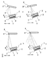
図5a−図5dは、本実施形態に係る位置検出素子53を用いた測距センサ8を採用した自律走行型掃除機Sにより姿見58の検知を試みる場面を示した図である。図5a,図5bは、姿見58の鏡面反射を生じる側の面58sが位置検出素子53を用いた測距センサ8に対向している場合を示す図、図5c,図5dは、姿見58の拡散反射を生じる側の面58dが位置検出素子53を用いた測距センサ8に対向している場合を示す図である。何れも発光素子52からの光を破線で、障害物58で反射した反射光を二点破線で、示してある。
(Structure and operating principle of distance sensor using position detector)
FIGS. 5a to 5d are views showing scenes in which an autonomous traveling type vacuum cleaner S employing the
障害物としては、一面側が鏡張りで形成されていて鏡面反射し、他面側が例えば木材で形成されていて拡散反射をする姿見58等を想定できる。姿見58は、人が自身の全身を映して確認するために用いられるのが通常であるから、床面Yに対して略垂直又は鏡面反射をする面58sが上向きになるように設置されるのが通常である。すなわち姿見58は、図5a,5cのように床面Yに対して略垂直に設けられる場合も、図5b,5dのように床面Yに対して鏡面反射を生じる側の面58sが上向きになるように設けられる場合もある。本実施形態によれば、このどちらの態様で姿見58が設置されていても、効果的にその存在を検知できる。
As the obstacle, it is possible to envisage a figure 58 or the like in which one surface side is formed with a mirror and is specularly reflected, and the other surface side is formed with, for example, wood and diffusely reflects. Since the figure 58 is usually used for a person to view and confirm his / her whole body, the figure 58 is installed so that the
位置検出素子53を用いた測距センサ8は、発光素子52及び位置検出素子53を備えた基板51、及び受光レンズ55をセンサ筺体50の内部に有している。受光レンズ55により、測距センサ8及び障害物58の位置関係に応じた位置検出素子53の場所に、反射光が入射する。
The
発光素子52は、光を発することができる。位置検出素子53は、位置検出素子53の受光面のどの位置に発光素子52が発する光の波長を持つ光が照射されたかを区別して出力できる。発光素子52としては、例えば赤外線LEDを用いることができるが、可視光や紫外線、レーザを発するLED等を用いても良い。
The
センサ筺体50は、基板51の面と垂直な方向に立設した面を基板50周囲に有しており、また、発光素子52及び位置検出素子53の間に、同じように基板51の面と垂直な方向に立設した仕切部材56を有している。仕切部材56により、発光素子52が発した光が直接位置検出素子53に入射しないようにできる。
The
位置検出素子53の前方には受光レンズ55が設けられている。受光レンズ55を介して位置検出素子53の反対側から受光レンズ55に近づく光は、受光レンズ55によって直線状に収束して、位置検出素子53に照射される。よって、発光素子52が発した光が障害物57表面で反射すると、その反射光が受光レンズ55によって直線状に収束する。この光は、位置検出素子53の受光面に照射される。受光面のどの位置に照射されるかは、センサ筺体50及び障害物58の位置関係に応じて決定する。測距センサ8の出力を利用して、自律走行型掃除機Sは、自身又は前方用測距センサ8から障害物58までの距離を測定できる。
A
(位置検出素子を用いた測距センサ8の発光素子52及び受光素子53の関係)
本実施形態の測距センサ8は、発光素子52が位置検出素子53より下側、すなわち、位置検出素子53が発光素子52より上側になるように自律走行型掃除機Sに取付けられているため、姿見のような障害物58の検知をより確実に行うことができる。以下、詳細を説明する。
(Relationship between the light emitting
The
まず、自律走行型掃除機Sが、姿見58の鏡面反射側の面58sに近づく場合(図5a,図5b)を説明する。
First, the case where the autonomously traveling cleaner S approaches the
例えば図5aのように鏡面反射側の面58sが略鉛直の場合、発光素子52が斜め上前方に発した光による反射光は斜め上方向に反射し、発光素子52より上方に位置する受光レンズ55に入射される。図5bのように鏡面反射側の面が上向きの場合も同様に受光レンズ55に入射されるが、この場合は特に、発光素子52が前方に発した光による反射光も受光レンズ55に入射されやすい。
For example, when the specular
また、図5c,図5dのように拡散反射側の面58dについては、鏡面反射よりも反射する範囲が広いため検知がより容易であるから、やはり姿見58を検知できる。
Further, as shown in FIGS. 5c and 5d, the
この際、発光素子52が下側、受光素子53が上側であるため、発光素子52が斜め下前方に発した光が床面Yで反射しても、受光素子53にまで入射する可能性が比較的小さい。また、本実施形態では、発光素子52及び受光素子53の上下位置の関係をこのように設定しているため、後述するように、測距センサ8を下向きではなく、水平又は上向きにすることが好ましい。この場合、床面Yに発光素子52が発した光がさらに到達し難いため、誤検知を抑制できる。すなわち、床面Yによる反射光で障害物の存在を誤検知する可能性を低減できる。そして、発光素子52としては、任意の方向に略同じ強さの光を発するものでもよいが、或る方向(以下、この方向を主方向と呼ぶ。)への強さが最も高く、その方向から離れるにつれて光の強さが低くなるものを用いるのが好ましい。本実施形態では、発光素子52として、基板51に垂直な方向が主方向となるように設けられた素子を用いている。すなわち、主方向である基板51に垂直な方向に発する光が最も強く、その主方向からずれるに従って比較的光が弱くなるように発するものを用いている。このような発光素子52としては、公知のLED等を用いることで実現できる。通常、LED等の主方向は、本実施形態の発光素子52のように表面中央、すなわち基板51に取付けたときに基板51に垂直な方向が主方向であるが、上述のように、その他の方向が主方向となるLED等を作成して用いても良い。なお、必ずしも発光素子52は直接基板51に取付けられている必要はない。この場合は、発光素子52の主方向が後述するように水平又は上向きになるように固定されていればよい。
At this time, since the
(位置検出素子を用いた測距センサ8の取付方向)
位置検出素子を用いた測距センサ8は、発光素子52の主方向が床面Yに対して水平又は上方を向くように、自律走行型掃除機Sに取付けられている。すなわち、本実施形態においては、基板51が水平又は上方を向くように測距センサ8が取付けられている。これにより、発光素子52が発した光が床面Yに反射して受光素子53に入射することで生じる誤検知を抑制できる。
(Mounting direction of the
The
すなわち、測距センサ8は、発光素子52の主方向が床面に対して0°(水平)に取付けられても良いが、例えば、床面に対して略垂直の姿見58の検知の容易さの観点、また、床面Yの誤検知可能性の低減の観点から、上向きに取付けられる方が好ましい。上向き角度は、水平な床面Yに対して1°以上にすることができるが、5°以上や10°以上が好ましく、15°以上がさらに好ましい。上向き角度の上限は、姿見58が通常置かれる角度(5°〜15°)を考慮すると、25°以下が好ましい。
In other words, the
なお、移動体としては、床面Yに対する測距センサ8の距離が略一定に保たれるものが好ましい。そのような移動体であれば、適切な測距センサ8の設置角度を容易に定めることができるからである。すなわち、移動体は、例えば、駆動輪2,3やクローラ等、床面Yの形状に沿って移動するものが好ましい。
In addition, as a moving body, the thing by which the distance of the ranging
また、センサ筐体50としては、本実施形態のように測距センサ8を独立した部材とする形状でもよいし、移動体としての自立駆動型掃除機Sのケース1等に凹部を設けたスペースとしてもよい。
In addition, the
[実施形態2]
本実施形態の構成は、以下の点を除き、実施形態1と同様にできる。
図6a−図6dは、本実施形態に係る位置検出素子53を用いた測距センサ8を採用した自律走行型掃除機Sにより姿見58の検知を試みる場面を示した図である。図6a,図6bは姿見58の鏡面反射を生じる側の面58sが位置検出素子53を用いた測距センサ8に対向している場合を示す図、図6c,図6dは姿見58の拡散反射を生じる側の面58dが位置検出素子53を用いた測距センサ8に対向している場合を示す図である。何れも発光素子52からの光を破線で、障害物58で反射した反射光を二点破線で、示してある。
[Embodiment 2]
The configuration of the present embodiment can be the same as that of the first embodiment except for the following points.
6a to 6d are diagrams showing a scene in which an autonomous traveling type vacuum cleaner S employing the
本実施形態では、発光素子52の前方に投光レンズ54が設けられている。発光素子52が発した光は、投光レンズ54によって直線状に収束して、センサ筐体50の外に進行する。これにより、発光素子52が発した光が斜め下前方に進んで床面Yに反射する可能性を低減できる。本実施形態においては、発光素子52が発した光が収束していることから、鏡面反射を生じる側の面58sを効果的に検知するには、測距センサ8を水平ではなく上向きに取付けることが好ましい。
In the present embodiment, a
[比較例]
図7は、比較例としての測距センサ80を自律走行型掃除機Sに取付けた場合に姿見58の検知を試みる場面を示した図である。図7a,図7bは、姿見58の鏡面反射を生じる側の面58sが測距センサ80に対向している場合を示している。図7c,図7dは、姿見58の拡散反射を生じる側の面58dが測距センサ80に対向している場合を示している。
[Comparative example]
FIG. 7 is a diagram illustrating a scene in which the detection of the
比較例における測距センサ80は、発光素子520が上側、受光素子530が下側に位置するように自律駆動型掃除機Sに取付けられている。このため、床面Yで反射した光が受光素子53に入射しやすく、誤検知が生じやすい。
The
また、上述のように姿見58は、鏡面反射の側の面58sが略垂直又は上向きになるように設置されるのが通常である。すると比較例の場合、少なくとも鏡面反射の側の面58sに近づいたとき(図7a,7b)は、発光素子520が発した光が受光素子530に入射し難い。これは特に、測距センサ8を上向きに取付けた場合に顕著である。したがって、姿見58の検知を行い難い。投光レンズ540を設けない場合も同様である。
Further, as described above, the
[実施形態3]
本実施形態の構成は、以下の点を除き、実施形態1又は2と同様にできる。
図8a,図8bは、自律走行型掃除機Sに取り付けられた本実施形態の測距センサ8を用いた場合に姿見58の鏡面反射側の面58sの検知を試みる場面を示した図である。図8aは姿見58が床面Yに対して略垂直である場合を、図8bは上向きである場合を示している。
[Embodiment 3]
The configuration of this embodiment can be the same as that of
FIGS. 8a and 8b are diagrams showing a scene in which the detection of the
本実施形態の発光素子52は、センサ筐体50に対して傾斜して取り付けられている。より具体的には、受光素子53及び受光レンズ55の側を向く方向に傾斜して取り付けられている。なお、投光レンズ54は発光素子52の傾斜角と略同一角で傾斜して設けられている。
The
このように測距センサ8を構成すると、センサ筐体50を斜めにして自律駆動型掃除機Sに取り付けずとも、実施形態1又は2と同様の効果を奏することができるため、ケース1への部材配置に際してデッドスペースを生じさせにくい。
If the
また、自律走行型掃除機Sに対して下向きに測距センサ8を取付けた場合であっても、発光素子52が床面に対して水平又は上向きであれば同様の効果を奏することができる。発光素子52の床面に対する角度は、水平(0°)でも良いが、例えば、床面に対して略垂直の姿見58の検知の容易さの観点から、上向きに取付けられる方が好ましい。上向き角度は、床面に対して1°以上にすることができるが、5°以上や10°以上が好ましく、15°以上がさらに好ましい。上向き角度の上限は、姿見58が通常置かれる角度(5°〜15°)を考慮すると、25°以下が好ましい。
Further, even when the
なお、発光素子52のみを傾斜して取り付けているため、測距センサ8自体を水平向きに取付けることができる。このため、受光レンズ55の角度を発光素子52に比して、より水平に近い角度にすることができる。。これにより、照明等からの外光が受光レンズ正面から入射されにくなり、測定値への影響を小さくすることができる。この場合の受光レンズ55及び受光素子53の角度は、それぞれ発光素子52よりも水平に近ければ特に制限されないが、床面Yの誤検知のおそれを低減する観点から、下向きではなく水平又は上向きであることが好ましい。
In addition, since only the
なお、本実施例では発光素子52を基板51に対して傾斜して取り付けているが、基板51自体を傾斜させ、発光素子52は基板51に略垂直に配置しても構わない。また、センサ8からの発光の主方向を傾斜させるために、投光レンズ54を調整しても構わない。また、発光素子52の光をセンサ8内で鏡面反射させ、投光方向を変えても構わない。これらのようにセンサ8からの発光の主方向を傾斜させた光の方向は配光分布を測定する、もしくはフォトダイオード等により出力が高くなる方向を計測することによる確認できる。
In the present embodiment, the
また、移動体として、例えばケース1が略円形の自律走行型掃除機Sを採用する場合、比較的左側面や右側面に部品が集中し易い。このため、部品のレイアウトの観点からは、本実施形態の測距センサ8は、左側面測距センサ8b又は右側面測距センサ8cとして採用するとさらに好ましい。
For example, when the autonomous traveling cleaner S having a substantially
[実施形態4]
本実施形態の構成は、以下の点を除き、実施形態1と同様にできる。
図9は本実施形態の測距センサ8の斜視図、図10a,図10bは、自律走行型掃除機Sに取り付けられた本実施形態の前方用測距センサ8を用いた場合に、床面に対して上向きに設けられた姿見58の鏡面反射側の面58sの検知を試みる場面を示した図である。図10aは側面図、図10bは上面図である。
[Embodiment 4]
The configuration of the present embodiment can be the same as that of the first embodiment except for the following points.
FIG. 9 is a perspective view of the
本実施形態の測距センサ8はフォトトランジスタにより、例えば赤外線を感知する。略直方体のセンサ筐体50にセンサ基板51が内蔵されている。センサ基板51には発光素子52と受光素子としてのフォトトランジスタ73が水平方向に並んで設けられている。また、仕切り部材56が発光素子52とフォトトランジスタ73の間に設けられている。
The
本実施形態の測距センサ8は、発光素子52及び受光素子73が水平方向に並んでいるため、鏡面反射側の面58sに対して略垂直に発光することが好ましい。したがって、測距センサ8は、発光素子52の主方向が水平又は下向きに取付けられることが好ましい。
In the
発光素子52の前方には投光レンズが設けられておらず、発光素子52の光は幅広い角度に進む。これにより、障害物が鏡面反射する場合でも、発光素子52の光が広範囲に投光されているため、フォトトランジスタ53に光が入射し易くなる。受光レンズは設けても良いし設けなくても良い。発光素子52の光は、水平方向が最も強く、水平方向からずれるに従って比較的光が弱くなるように発するものを用いると好ましい。これにより、床面に反射した光がフォトトランジスタ73に入射しても、その強度が小さいため、誤検知するおそれを低減できる。なお、実施形態1と同様、等方性の光源、すなわち主方向がない又は前方向が主方向と解釈できる光源を用いても良い。
A light projection lens is not provided in front of the
測距センサ8は、自律走行型掃除機Sに対して、発光素子52とフォトトランジスタ73とが略同じ高さに位置するように取付けられている。また、発光素子52の主方向は床面側、すなわち斜め下方に向いている。このようにすることで、上向きに傾斜して設置されている姿見の鏡面に対して略垂直に投光できる。このため、反射光は、発光素子52と略同じ高さに位置するフォトトランジスタ73に向かって反射する。姿見が床面に対して略垂直の場合は、発光素子52が幅広い角度に投光することから、やはり受光素子73に反射光が入射できる。
The
受光素子73が発光素子53と略同じ高さであるため、床面Yでの反射による誤検知の可能性も比較例に比して低減できる。
Since the
よって、本実施形態によっても実施形態1と同様の効果を奏することができる。なお、測距センサ8は、水平でも良いが、例えば、1°以上、25°以下の範囲で下向きに傾斜させると好ましい。また、受光素子73はフォトトランジスタでなく、フォトダイオードでもよい。
Therefore, the present embodiment can provide the same effects as those of the first embodiment. The
なお、実施形態3と同様にして、筐体50に対して発光素子52が下向きとなるように傾斜させても良い。また、実施形態1と同様にして、位置検出素子53を用いた測距センサ8を採用し、発光素子52及び受光素子53が略同一高さになるよう取付けても良い
Note that the
1 ケース
2,3 駆動輪
4 補助輪
5 回転ブラシ
6 窓
7 サイドブラシ
8 前方用測距センサ
9 充電池
11 吸引ファン
12 集塵ケース
14 吸口
15 バンパセンサ
16 床面用測距センサ
52 赤外線LED(発光素子)
53 位置検出素子(受光素子)
54 投光レンズ
55 受光レンズ
58 鏡面反射が主となる面及び拡散反射が主となる面を有する障害物
58s 鏡面反射が主となる面
58d 拡散反射が主となる面
73 フォトトランジスタ(受光素子)
S 自律走行型掃除機
DESCRIPTION OF
53 Position detection element (light receiving element)
54
S autonomous running type vacuum cleaner
Claims (6)
前記発光素子が前記受光素子より下側に位置するように、前記センサが取付けられ、
当該移動体が床面に設置された際、前記発光素子の主方向が水平又は上向きであることを特徴とする移動体。 A moving body that includes a sensor in which a light emitting element and a light receiving element are arranged in a housing and moves on a floor surface,
The sensor is attached so that the light emitting element is located below the light receiving element,
A moving body characterized in that when the moving body is installed on a floor surface, the main direction of the light emitting element is horizontal or upward.
前記発光素子の前方に投光レンズを有することを特徴とする請求項1に記載の移動体。 When the moving body is installed on the floor, the main direction of the light emitting element is upward by 1 ° or more,
The moving body according to claim 1, further comprising a light projecting lens in front of the light emitting element.
前記受光素子又は前記受光素子前方に設けられた受光レンズは、前記発光素子の向く方向に比して、水平な向きに取付けられていることを特徴とする請求項1又は2に記載の移動体。 The light emitting element is attached in a direction that is substantially perpendicular to the substrate to which the light emitting element is attached and is inclined in a direction facing the light receiving element,
The moving body according to claim 1 or 2, wherein the light receiving element or a light receiving lens provided in front of the light receiving element is attached in a horizontal direction as compared to a direction in which the light emitting element faces. .
前記発光素子と前記受光素子とが略同じ高さに位置するように、前記センサが取付けられ、
前記発光素子の主方向は、当該移動体が床面に設置された際、水平又は下向きであることを特徴とする移動体。 A moving body that includes a sensor in which a light emitting element and a light receiving element are arranged in a housing and moves on a floor surface,
The sensor is attached so that the light emitting element and the light receiving element are located at substantially the same height,
The moving body characterized in that a main direction of the light emitting element is horizontal or downward when the moving body is installed on a floor surface.
Priority Applications (1)
| Application Number | Priority Date | Filing Date | Title |
|---|---|---|---|
| JP2016015036A JP6626723B2 (en) | 2016-01-29 | 2016-01-29 | A moving object that moves on the floor |
Applications Claiming Priority (1)
| Application Number | Priority Date | Filing Date | Title |
|---|---|---|---|
| JP2016015036A JP6626723B2 (en) | 2016-01-29 | 2016-01-29 | A moving object that moves on the floor |
Publications (2)
| Publication Number | Publication Date |
|---|---|
| JP2017134697A true JP2017134697A (en) | 2017-08-03 |
| JP6626723B2 JP6626723B2 (en) | 2019-12-25 |
Family
ID=59502683
Family Applications (1)
| Application Number | Title | Priority Date | Filing Date |
|---|---|---|---|
| JP2016015036A Active JP6626723B2 (en) | 2016-01-29 | 2016-01-29 | A moving object that moves on the floor |
Country Status (1)
| Country | Link |
|---|---|
| JP (1) | JP6626723B2 (en) |
Cited By (1)
| Publication number | Priority date | Publication date | Assignee | Title |
|---|---|---|---|---|
| JP2022517569A (en) * | 2019-01-04 | 2022-03-09 | 云鯨智能科技(東莞)有限公司 | Mobile robot |
Citations (3)
| Publication number | Priority date | Publication date | Assignee | Title |
|---|---|---|---|---|
| JP2003280737A (en) * | 2002-03-25 | 2003-10-02 | Matsushita Electric Ind Co Ltd | Movable device |
| JP2007193538A (en) * | 2006-01-18 | 2007-08-02 | Sharp Corp | Self-running traveling object |
| JP2014013551A (en) * | 2012-07-05 | 2014-01-23 | Sharp Corp | Self-propelled apparatus |
-
2016
- 2016-01-29 JP JP2016015036A patent/JP6626723B2/en active Active
Patent Citations (3)
| Publication number | Priority date | Publication date | Assignee | Title |
|---|---|---|---|---|
| JP2003280737A (en) * | 2002-03-25 | 2003-10-02 | Matsushita Electric Ind Co Ltd | Movable device |
| JP2007193538A (en) * | 2006-01-18 | 2007-08-02 | Sharp Corp | Self-running traveling object |
| JP2014013551A (en) * | 2012-07-05 | 2014-01-23 | Sharp Corp | Self-propelled apparatus |
Cited By (1)
| Publication number | Priority date | Publication date | Assignee | Title |
|---|---|---|---|---|
| JP2022517569A (en) * | 2019-01-04 | 2022-03-09 | 云鯨智能科技(東莞)有限公司 | Mobile robot |
Also Published As
| Publication number | Publication date |
|---|---|
| JP6626723B2 (en) | 2019-12-25 |
Similar Documents
| Publication | Publication Date | Title |
|---|---|---|
| US11846937B2 (en) | Autonomous cleaner | |
| JP5138895B2 (en) | Traveling robot position sensing device and robot cleaner provided with the same | |
| US11103115B2 (en) | Sensor module and robot cleaner having the same | |
| US11547263B2 (en) | Autonomous cleaner | |
| JP4268911B2 (en) | Self-propelled vacuum cleaner | |
| US10362916B2 (en) | Autonomous cleaner | |
| US10420448B2 (en) | Autonomous cleaner | |
| US8525975B2 (en) | Detector device and mobile robot having the same | |
| US20170336798A1 (en) | Autonomous cleaner | |
| US10342405B2 (en) | Autonomous cleaner | |
| US10524628B2 (en) | Autonomous cleaner | |
| US8306662B2 (en) | Position detection device for mobile robot and robot cleaner including the same | |
| JP2007193538A (en) | Self-running traveling object | |
| KR20080093768A (en) | Position sensing device of traveling robot and robot cleaner using the same | |
| US10463221B2 (en) | Autonomous cleaner | |
| JP6626723B2 (en) | A moving object that moves on the floor | |
| JP2018153375A (en) | Electric apparatus, autonomous traveling vacuum cleaner as electric apparatus and system including electric apparatus and base | |
| KR20220021980A (en) | Cleaning robot and controlling method thereof | |
| KR20020080900A (en) | Obstacle detecting apparatus of robot cleaner and method therefor | |
| KR102045002B1 (en) | Robot cleaner | |
| JP2003280737A (en) | Movable device | |
| TWI671053B (en) | Detecting system of autonomous robot | |
| KR20220003780A (en) | Charging Device For Robot Cleaner and Controlling Method of Robot Cleaner using the same |
Legal Events
| Date | Code | Title | Description |
|---|---|---|---|
| A521 | Request for written amendment filed |
Free format text: JAPANESE INTERMEDIATE CODE: A523 Effective date: 20160201 |
|
| RD04 | Notification of resignation of power of attorney |
Free format text: JAPANESE INTERMEDIATE CODE: A7424 Effective date: 20170120 |
|
| RD04 | Notification of resignation of power of attorney |
Free format text: JAPANESE INTERMEDIATE CODE: A7424 Effective date: 20170126 |
|
| A621 | Written request for application examination |
Free format text: JAPANESE INTERMEDIATE CODE: A621 Effective date: 20180214 |
|
| A521 | Request for written amendment filed |
Free format text: JAPANESE INTERMEDIATE CODE: A523 Effective date: 20180215 |
|
| A977 | Report on retrieval |
Free format text: JAPANESE INTERMEDIATE CODE: A971007 Effective date: 20181225 |
|
| A131 | Notification of reasons for refusal |
Free format text: JAPANESE INTERMEDIATE CODE: A131 Effective date: 20190108 |
|
| A521 | Request for written amendment filed |
Free format text: JAPANESE INTERMEDIATE CODE: A523 Effective date: 20190220 |
|
| A131 | Notification of reasons for refusal |
Free format text: JAPANESE INTERMEDIATE CODE: A131 Effective date: 20190611 |
|
| A521 | Request for written amendment filed |
Free format text: JAPANESE INTERMEDIATE CODE: A523 Effective date: 20190805 |
|
| TRDD | Decision of grant or rejection written | ||
| A01 | Written decision to grant a patent or to grant a registration (utility model) |
Free format text: JAPANESE INTERMEDIATE CODE: A01 Effective date: 20191105 |
|
| A61 | First payment of annual fees (during grant procedure) |
Free format text: JAPANESE INTERMEDIATE CODE: A61 Effective date: 20191202 |
|
| R150 | Certificate of patent or registration of utility model |
Ref document number: 6626723 Country of ref document: JP Free format text: JAPANESE INTERMEDIATE CODE: R150 |