JP2017133732A - Heat source machine - Google Patents
Heat source machine Download PDFInfo
- Publication number
- JP2017133732A JP2017133732A JP2016012562A JP2016012562A JP2017133732A JP 2017133732 A JP2017133732 A JP 2017133732A JP 2016012562 A JP2016012562 A JP 2016012562A JP 2016012562 A JP2016012562 A JP 2016012562A JP 2017133732 A JP2017133732 A JP 2017133732A
- Authority
- JP
- Japan
- Prior art keywords
- combustion
- temperature sensor
- temperature
- heat source
- control unit
- Prior art date
- Legal status (The legal status is an assumption and is not a legal conclusion. Google has not performed a legal analysis and makes no representation as to the accuracy of the status listed.)
- Pending
Links
Images


Abstract
Description
本発明は、熱源機に関し、特に缶石詰まり検知用サーミスタなどの所定の温度センサの故障や取付不良などの異常を報知する機能を有するものに関する。 The present invention relates to a heat source device, and more particularly to a device having a function of notifying a malfunction of a predetermined temperature sensor such as a clogging clogging detection thermistor or an abnormality such as a mounting failure.
本願出願人は、例えば、下記の特許文献1に、缶石詰まり検知用サーミスタを備えた給湯装置(熱源機)を開示している。この缶石詰まり検知用サーミスタは、例えば熱交換器近傍で燃焼缶体の背面に取り付けられる。熱交換器配管内の缶石の付着量が多いほど給湯流量が低減して燃焼缶体の温度が上昇していくため、缶石詰まり検知用サーミスタの検知温度に基づいて缶石が詰まっているか否かをマイコン(制御部)により判定することができる。
The applicant of the present application discloses, for example, a hot water supply device (heat source device) including a thermistor for detecting clogging of scale stone in
上記缶石詰まり検知用サーミスタは高温に曝されるためオープン故障の可能性が比較的高くなるが、オープン故障時には缶体温度が上昇しても低温であるとマイコンが誤検知してしまい、缶石詰まりを正常に検出できなくなる。 The above-mentioned clogging clogging thermistor is exposed to high temperatures, so the possibility of an open failure is relatively high. However, even if the can body temperature rises at the time of an open failure, the microcomputer will falsely detect that the can temperature is low. Stone clogging cannot be detected normally.
そのため、缶石詰まり検知用サーミスタが缶体温度の上昇を正常に検出できるか否かを判定する処理を所定のタイミング毎に行うことが好ましい。例えば、燃焼中は缶体温度は必ず上昇してサーミスタの抵抗値は小さくなっていくが、オープン故障時には缶体温度が上昇しても絶縁状態となってマイコンによる検出温度としては低温となる。したがって、燃焼開始時および燃焼継続1時間毎に缶石詰まり検知用サーミスタの検出温度が正常範囲、すなわち高温になっているか否かを所定の異常基準値(例えば35℃)との比較により判定し、異常基準値未満であると連続して判定された異常回数が所定回数(例えば10回)に達すると缶石詰まり検知用サーミスタの異常であるものと判断して、缶石詰まり検知用サーミスタ異常を示す所定のエラー報知を行うとともに燃焼動作を禁止するよう構成することができる。ここで異常回数が所定回数に達するまでエラー報知を行わないのは、缶石詰まり検知用サーミスタは缶石の詰まりを直接的に検出するものではなく、缶石詰まりによって上昇する缶体温度に基づいて間接的に検出するものであり、缶体温度は外気温や給水温度その他の要因の影響をも受けるため、複数回の缶体温度の異常検出によって缶石詰まりであると判定することで、誤判定を防止するためである。 For this reason, it is preferable to perform a process for determining whether or not the canister clogging detection thermistor can normally detect the increase in the can body temperature at every predetermined timing. For example, during combustion, the temperature of the can increases without fail and the resistance value of the thermistor decreases. However, even if the temperature of the can increases, the insulation becomes inactive and the temperature detected by the microcomputer is low. Therefore, at the start of combustion and every hour of continuous combustion, it is determined by comparison with a predetermined abnormality reference value (for example, 35 ° C.) whether the detected temperature of the scale clogging detection thermistor is in the normal range, that is, high temperature. When the number of abnormalities continuously determined to be less than the abnormal reference value reaches a predetermined number (for example, 10 times), it is determined that the thermite clogging detection thermistor is abnormal, and the clogging clogging detection thermistor abnormality is detected. It is possible to perform a predetermined error notification indicating that the combustion operation is prohibited. Here, the error notification is not performed until the number of abnormalities reaches a predetermined number of times. The thermistor for detecting clogging of stones does not directly detect clogging of stones, but is based on the temperature of the body rising due to clogging of stones. Because the can body temperature is also affected by the outside air temperature, the water supply temperature and other factors, by determining that the can body is clogged by detecting the abnormality of the can body temperature multiple times, This is to prevent erroneous determination.
缶石詰まり検知用サーミスタ異常のエラー報知がなされた場合には、メンテナンスマンによって缶石詰まり検知用サーミスタの交換作業を行うところ、交換した缶石詰まり検知用サーミスタの初期不良や、缶石詰まり検知用サーミスタの施工不良等によって交換後の缶石詰まり検知用サーミスタが缶体温度の上昇を正常に検出できない場合がある。 When an error notification for the detection of clogged clogging thermistors is given, a maintenance man replaces the thermistor for clogging clogged clogging detection. The thermistor for detecting clogging of scales after replacement may not be able to normally detect an increase in the temperature of the can body due to a defective construction of the thermistor for use.
この場合、初期不良や施工不良による上記エラー報知がなされるのは異常基準値未満であるとの判定回数が所定回数に達した後であり、例えば1時間毎に10回連続して判定された場合にエラー報知を行うよう構成されている場合には10時間という長い時間を要する。 In this case, the error notification due to the initial failure or the construction failure is made after the predetermined number of times that the error is less than the abnormality reference value has been reached, for example, 10 times continuously determined every hour. In such a case, a long time of 10 hours is required when the error notification is configured.
したがって、メンテナンスマンによる缶石詰まり検知用サーミスタの交換作業後、すぐに缶石詰まり検知用サーミスタの初期不良や施工不良を気付くことができず、後日あらためてメンテマンスマンが修理に出向く必要があるという問題がある。 Therefore, after the maintenance man replaces the clogging clogging thermistor, the initial clogging of the clogging clogging detection thermistor and the installation failure cannot be noticed immediately, and the maintenance man must return to repair at a later date. There is.
そこで、本発明は、缶石詰まり検知用サーミスタなどの所定の温度センサの検知温度が正常範囲外であるとの判定が複数回行われた場合に当該温度センサの異常であると判断する制御部を備える熱源機において、温度センサの交換後に迅速に当該温度センサが異常であるか否かを判断できるようにすることを目的とする。 Accordingly, the present invention provides a control unit that determines that the temperature sensor is abnormal when the detection temperature of a predetermined temperature sensor such as a clogging clogging detection thermistor is determined to be outside the normal range a plurality of times. An object of the present invention is to quickly determine whether or not the temperature sensor is abnormal after the temperature sensor is replaced.
上記目的を達成するために、本発明は、次の技術的手段を講じた。 In order to achieve the above object, the present invention takes the following technical means.
すなわち、本発明は、所定部位の温度を検出する温度センサと、記憶手段を有する制御部とを備え、該制御部は、前記温度センサの検出温度が正常範囲外であるか否かを所定のタイミング毎に判定するとともに正常範囲外であるとの異常判定カウント数が2以上の所定回数に達すると所定のエラー報知を行う熱源機において、前記制御部は、前記異常判定カウント数が前記所定回数に達すると前記温度センサの異常である旨の異常情報を前記記憶手段に記憶するよう構成されているとともに、前記記憶手段に前記異常情報が記憶されているときは前記所定回数よりも少ない前記異常判定カウント数で前記エラー報知を行うよう構成されていることを特徴とするものである(請求項1)。 That is, the present invention includes a temperature sensor that detects the temperature of a predetermined part and a control unit having a storage unit, and the control unit determines whether or not the temperature detected by the temperature sensor is outside a normal range. In the heat source machine that performs a predetermined error notification when the abnormality determination count number that is determined at each timing and is outside the normal range reaches a predetermined number of 2 or more, the control unit is configured so that the abnormality determination count number is the predetermined number of times. Is configured to store in the storage means abnormality information indicating that the temperature sensor is abnormal, and when the abnormality information is stored in the storage means, the abnormality is less than the predetermined number of times. The error notification is performed based on the determination count number (Claim 1).
かかる本発明の熱源機によれば、電源再投入などによるリセット後、記憶手段に異常情報が記憶されていなければ、正常範囲外であるとの異常判定カウント数が通常通り所定回数に達するまでエラー報知を行わない。しかし、前回運転時に異常判定カウント数が所定回数に達することにより記憶手段に異常情報が記憶されている場合には、リセット後に所定回数よりも少ない異常判定カウント数(例えば1回)でエラー報知が行われる。したがって、温度センサの交換等のメンテナンス後に、所定回数よりも少ない異常判定カウント数(例えば1回)でエラー報知が行われ、交換された新しい温度センサの初期不良や施工不良を速やかに検知できる。 According to such a heat source device of the present invention, after the reset by turning on the power again or the like, if no abnormality information is stored in the storage means, the error determination count number of being out of the normal range will be an error until it reaches a predetermined number as usual. Do not broadcast. However, when the abnormality information is stored in the storage means when the abnormality determination count reaches a predetermined number during the previous operation, an error notification is issued with an abnormality determination count less than the predetermined number after reset (for example, once). Done. Therefore, after maintenance such as replacement of the temperature sensor, error notification is performed with an abnormality determination count number (for example, once) smaller than a predetermined number of times, and an initial failure or a construction failure of the replaced new temperature sensor can be detected quickly.
なお、所定のタイミングは、例えば所定時間毎(1時間毎など)であってもよいし、燃焼動作開始毎であってもよいし、燃焼開始時及び燃焼動作継続1時間毎であってもよいし、その他適宜のものであってよい。 Note that the predetermined timing may be, for example, every predetermined time (such as every hour), every time the combustion operation is started, or every hour when the combustion is started and when the combustion operation is continued. However, other appropriate ones may be used.
また、異常判定カウント数は、RAMやCPU内部レジスタなどの揮発性メモリに記憶保持しておくことができ、この場合、制御部の電源を遮断する操作、例えば電源コンセントを電源プラグから抜く操作や電源スイッチのオフ操作によって異常判定カウント数を初期化できる。勿論、異常判定カウント数を初期化するためのリセットスイッチを設けておいてもよいし、リセットスイッチの操作によって制御部が異常判定カウント数の初期化処理を行うのであればEEPROMなどの書き換え可能不揮発性メモリに異常判定カウント数を記憶保持しておくことも可能である。 In addition, the abnormality determination count number can be stored in a volatile memory such as a RAM or a CPU internal register. In this case, an operation for shutting off the power of the control unit, for example, an operation for unplugging the power outlet from the power plug, The abnormality determination count can be initialized by turning off the power switch. Of course, a reset switch for initializing the abnormality determination count number may be provided, and if the control unit initializes the abnormality determination count number by operating the reset switch, a rewritable nonvolatile memory such as an EEPROM is provided. It is also possible to store the abnormality determination count number in the memory.
また、記憶手段は、EEPROMなどの書き換え可能不揮発性メモリであることが好ましいが、電池などでバックアップするのであればRAMなどの揮発性メモリを用いることも可能である。また、リセットスイッチの操作により異常判定カウント数の初期化処理を行う場合であって、電源遮断によって前記異常情報が消去されることを許容する設計であるならばバックアップ電源無しで揮発性メモリを前記記憶手段として用いることも可能である。 The storage means is preferably a rewritable nonvolatile memory such as an EEPROM, but a volatile memory such as a RAM may be used as long as it is backed up by a battery or the like. In addition, if the abnormality determination count number is initialized by operating the reset switch, and the design allows the abnormality information to be erased by turning off the power, the volatile memory can be stored without a backup power source. It can also be used as storage means.
また、異常情報は、判定カウント数とは別の情報(例えば異常時は1、正常時は0となるフラグなど)として記憶手段に記憶することもできるが、所定回数以上の判定カウント数そのものを前記「異常情報」として記憶手段に記憶することもできる。すなわち、書き換え可能不揮発性メモリに判定カウント数を記憶しておき、該判定カウント数が所定回数以上となったときが「前記記憶手段に前記異常情報が記憶されているとき」であってよい。この場合でも、電源遮断によって判定カウント数の記憶は消去されないので、温度センサ交換後の初回電源投入時の初回燃焼動作時の最初の温度センサの検出温度の判定において正常範囲外であれば前回運転時からの異常判定の累計回数が所定回数に達しているため、今回の電源投入後の判定カウント数が1回で即座にエラー報知が行われる。 In addition, the abnormality information can be stored in the storage means as information different from the determination count number (for example, a flag that is 1 at the time of abnormality and 0 at the time of normality). It can also be stored in the storage means as the “abnormal information”. That is, the determination count number may be stored in the rewritable nonvolatile memory, and the time when the determination count number is equal to or greater than a predetermined number may be “when the abnormality information is stored in the storage unit”. Even in this case, since the memory of the judgment count number is not erased due to the power shutoff, if it is outside the normal range in the judgment of the detected temperature of the first temperature sensor at the first combustion operation at the first power on after the temperature sensor replacement, the previous operation is performed. Since the cumulative number of times of abnormality determination from the time has reached a predetermined number, the error notification is immediately performed when the determination count after the current power-on is one.
上記本発明の熱源機において、前記制御部は、前記所定のタイミングで前記温度センサの検出温度が正常範囲内であると判定したとき前記異常情報を前記記憶手段から消去するものであってよい(請求項2)。これによれば、交換された新しい温度センサの初期不良や施工不良があった場合には速やかにエラー報知を行う制御構成としつつも、温度センサの検出温度が正常範囲内で判定したときは異常情報を記憶手段から消去することによって、正常範囲外であるとの異常判定カウント数が連続して所定回数に達するまでエラー報知を行わないようにすることができる。 In the heat source apparatus of the present invention, the control unit may delete the abnormality information from the storage unit when it is determined that the temperature detected by the temperature sensor is within a normal range at the predetermined timing ( Claim 2). According to this, when there is an initial failure or construction failure of a new temperature sensor that has been replaced, a control configuration that promptly notifies an error, but an abnormality occurs when the temperature detected by the temperature sensor is determined within the normal range. By erasing the information from the storage means, it is possible to prevent the error notification from being performed until the abnormality determination count number that is out of the normal range continuously reaches a predetermined number.
また、前記制御部は、前記記憶手段に前記異常情報が記憶されているときは1回の異常判定カウント数で前記エラー報知を行うよう構成することが好ましく(請求項3)、これによれば、交換された新しい温度センサの初期不良や施工不良をより迅速に検知できる。 Further, it is preferable that the control unit is configured to perform the error notification with one abnormality determination count when the abnormality information is stored in the storage means (claim 3). The initial failure and construction failure of the replaced new temperature sensor can be detected more quickly.
前記制御部は、前記所定のタイミングで前記温度センサの検出温度が正常範囲内であると判定したときに前記異常判定カウント数を初期化するよう構成することが好ましい(請求項4)。これによれば、所定のタイミングでの前記温度センサの検出温度が正常範囲外であるとの異常判定が連続して所定回数なされた場合にのみエラー報知を行わせることができ、様々な外因によって温度センサが異常である旨のエラー報知が誤って行われてしまうことを回避できる。 Preferably, the controller is configured to initialize the abnormality determination count when it is determined that the temperature detected by the temperature sensor is within a normal range at the predetermined timing. According to this, error notification can be performed only when the abnormality determination that the detected temperature of the temperature sensor at a predetermined timing is outside the normal range is made a predetermined number of times continuously, due to various external factors. It is possible to avoid erroneous notification that the temperature sensor is abnormal.
上記熱源機は、前記制御部によって燃焼動作制御される燃焼部をさらに備えることができる。この場合、前記温度センサは、前記燃焼部の燃焼動作により温度変化する所定部位の温度を検出するものであり、前記制御部は、前記燃焼部の燃焼動作中に前記所定のタイミングでの判定を行うとともに、燃焼動作中の前記温度センサの検出温度が前記燃焼部の非燃焼動作時の温度範囲内であれば正常範囲外であると判定するよう構成できる(請求項5)。これによれば、燃焼動作によって正常であれば必ず温度上昇する部位の温度が燃焼動作していないときの温度範囲内(例えば35度未満)のままであれば正常範囲外であると判定することで、より的確かつ確実に温度センサの異常を検知できる。 The heat source device may further include a combustion unit whose combustion operation is controlled by the control unit. In this case, the temperature sensor detects the temperature of a predetermined portion that changes in temperature by the combustion operation of the combustion section, and the control section performs the determination at the predetermined timing during the combustion operation of the combustion section. In addition, if the temperature detected by the temperature sensor during the combustion operation is within the temperature range during the non-combustion operation of the combustion section, it can be determined that it is outside the normal range. According to this, if the temperature of the part where the temperature rises without fail when the combustion operation is normal remains within the temperature range when the combustion operation is not performed (for example, less than 35 degrees), it is determined that it is out of the normal range. Thus, the abnormality of the temperature sensor can be detected more accurately and reliably.
また、上記熱源機は、前記制御部によって燃焼動作制御される燃焼部と、該燃焼部が発生する燃焼ガスによって配管内の通水を熱交換加熱する熱交換器と、該熱交換器及び前記燃焼部を収容する燃焼缶体とをさらに備えることができる。この場合、前記温度センサは缶石詰まり検知用サーミスタであり、前記熱交換器の配管は上下方向複数段構成とされるとともに下段側から上段側に向けて通水されるよう構成され、前記缶石詰まり検知用サーミスタは、最下段の配管の下流側端部近傍の側方で前記燃焼缶体の外側面に取り付けられているものとすることができる(請求項6)。これによれば、缶石詰まりによって最も温度上昇する部位の温度に基づいて温度センサ(缶石詰まり検知用サーミスタ)の異常を判定することとなるため、外因の影響を極小化してより的確かつ確実に温度センサの異常を検知できる。 In addition, the heat source machine includes a combustion unit whose combustion operation is controlled by the control unit, a heat exchanger that heat-exchanges and heats water in a pipe using combustion gas generated by the combustion unit, the heat exchanger, and the heat exchanger A combustion can body that houses the combustion section may be further provided. In this case, the temperature sensor is a thermite clogging detection thermistor, and the pipe of the heat exchanger is configured to have a plurality of stages in the vertical direction and configured to pass water from the lower stage side to the upper stage side. The stone clogging detection thermistor may be attached to the outer surface of the combustion can body on the side near the downstream end of the lowermost pipe (Claim 6). According to this, since the abnormality of the temperature sensor (thermistor for detecting clogging of scale stone) is judged based on the temperature of the part where the temperature rises most due to clogging of scale stone, the influence of external factors is minimized and more accurate and reliable. It is possible to detect abnormalities in the temperature sensor.
以上説明したように、本発明によれば、温度センサのメンテナンス後に迅速に当該温度センサが異常であるか否かを判断できるようにしつつ、通常時には所定回数以上の異常判定カウント数に達するまでエラー報知を行わないことで誤報知を低減できる。 As described above, according to the present invention, it is possible to quickly determine whether or not the temperature sensor is abnormal after maintenance of the temperature sensor, and at the normal time, the error is detected until the abnormality determination count number reaches a predetermined number or more. Misreporting can be reduced by not performing reporting.
以下、本発明の実施形態を図面に基づいて説明する。 Hereinafter, embodiments of the present invention will be described with reference to the drawings.
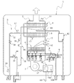
図1は、本発明の一実施形態に係る熱源機としての潜熱回収型高効率給湯装置を示しており、該給湯装置は、ハウジング1内に内蔵された燃焼缶体2及び給湯回路3を備えている。缶体2内部には、燃焼ガスを生成する燃焼部4と、該燃焼部4の上方に配置された一次熱交換器5と、該一次熱交換器5のさらに上方に配置された二次熱交換器6(凝縮熱交換器)とが設けられている。なお、燃焼部4に対して燃焼用空気を供給する送風ファン7が燃焼部4の下方に配設されている。
FIG. 1 shows a latent heat recovery type high-efficiency hot water supply apparatus as a heat source apparatus according to an embodiment of the present invention. The hot water supply apparatus includes a combustion can
燃焼部4は、図示例では4つの燃焼領域に区分されており、各燃焼領域はそれぞれ複数本のバーナによって形成されている。各バーナは、図2にも示すように長孔状の炎口を有し、該炎口は前後方向に延設されている。各燃焼領域には、燃料ガス供給源側から燃焼用燃料として燃料ガスを供給するガス供給管8が接続されている。このガス供給管8には、燃料ガス供給源側から順に、元栓としての元ガス電磁弁9と、ガス供給量を調整するガス比例弁10とが設けられている。このガス比例弁10の下流側でガス供給管8が各燃焼領域毎に分岐されている。各燃焼領域に対応して第1〜第4の能力切替弁SV1〜SV4が個別に設けられており、各能力切替弁SV1〜SV4を開閉することによって各燃焼領域への燃料ガスの供給を個別に制御可能となっている。各燃焼領域に供給された燃料ガスは、各バーナ毎に設けられたガス通路を介して各バーナに供給され、バーナ内で燃料ガスと燃焼用空気が混合され、該混合ガスが燃焼することによって燃焼ガスが生成される。
The
これにより、図2に示すように、4つの能力切替弁SV1〜SV4の選択的開閉制御によって燃焼部4の燃焼領域の大きさを複数の能力段数(図示例では、第1の燃焼領域のみを燃焼させる1段、第2の燃焼領域のみを燃焼させる2段、第1及び第2の燃焼領域を燃焼させる3段、第1〜第3の燃焼領域を燃焼させる4段、第1及び第4の燃焼領域を燃焼させる5段、並びに、第1〜第4のすべての燃焼領域を燃焼させる6段、の計6段階。なお、図2において、各段数を示す数字を四角囲みで表記している。)に切替制御可能に構成されているとともに、ガス比例弁10の開度制御により各能力段数における燃料ガスの供給量を調整することによって、各能力段数毎に燃焼熱量(給湯号数)を所定範囲で変更制御可能に構成されている。隣接する段数の下段側の能力段数の大燃焼側の燃焼熱量と上段側の能力段数の小燃焼側の燃焼熱量とはオーバーラップされ、これにより燃焼部4全体の燃焼熱量を、第1の燃焼領域のみをバーナの最小燃焼能力で燃焼させる最小燃焼熱量(例えば給湯号数換算で3号)から、第1〜第4の燃焼領域のすべてを最大燃焼能力で燃焼させる最大燃焼熱量(例えば給湯号数換算で24号)まで、連続的に変更調整可能としている。
As a result, as shown in FIG. 2, the size of the combustion region of the
一次熱交換器5は、燃焼部4で生じる燃焼ガスの顕熱を回収するものであり、二次熱交換器6は、一次熱交換器5において回収しきれなかった燃焼ガスの熱エネルギー、すなわち潜熱を回収して一次熱交換器5での加熱前に湯水を予熱するためのものである。
The primary heat exchanger 5 recovers the sensible heat of the combustion gas generated in the
一次熱交換器5は、図2に示すように、通水配管5aと、該通水配管5aの表面に設けられた多数のプレートフィン5bとを備えている。通水配管5aは、前後方向に並設された複数の直管部Cを蛇行状に接続してなる下段部と、該下段部の上方で同じく前後方向に並設された複数の直管部Cを蛇行状に接続してなる上段部とから上下2段構成となされており、下段部の下流側端部と上段部の上流側端部とが接続されている。各直管部Cは左右方向に延設されており、各プレートフィン5bにはすべての直管部Cが貫通接続されている。多数のプレートフィン5bは左右方向にわずかに間隔を開けつつ整列配置されており、これら多数のプレートフィン5bの背面側側縁は、燃焼缶体2の背面側側板2aに当接され、好ましくは溶接固定されている。
As shown in FIG. 2, the primary heat exchanger 5 includes a
この燃焼缶体2の背面側側板2aの外側面には、取付台座12を介して缶石詰まり検知用サーミスタ13が着脱自在に取付固定されている。特に、本実施形態では、図1及び図2に示すように、一次熱交換器5の通水配管5aの下段部の背面側であって、通水配管5aの下段部の通水下流側端部近傍にサーミスタ13が設けられている。さらに、本実施形態では、燃焼部4の第2の燃焼領域(第2の能力切替弁SV2に対応する領域)の上方にサーミスタ13を設けている。これは、実際の給湯動作において第2の燃焼領域が最も使用頻度の高い燃焼領域であり、燃焼動作中に燃焼部4から最も大きな熱量を受けている頻度が最も高いためである。
A scale
給湯回路3は、給水接続口から給水を受けた水道水等を二次熱交換器6に入水させる入水路31と、二次熱交換器6及び一次熱交換器5で熱交換加熱された湯を出湯させる出湯路32と、入水路31から分岐して出湯路32に冷水を供給するバイパス路33とを備えている。バイパス路33にはバイパス流量制御弁34が設けられ、バイパス路33を介したバイパス流量を調節することによって出湯湯温を制御可能となっている。バイパス路33への分岐部よりも下流側で入水路31には缶体流量センサ35と、入水温度センサ(入水サーミスタ)36とが設けられている。バイパス路33との合流部よりも上流側で出湯路32には、出湯温度センサ(缶体サーミスタ)37と、缶体流量制御弁38とが設けられている。また、バイパス路33との合流部よりも下流側で出湯路32には出湯温度センサ(出湯サーミスタ)39が設けられている。
The hot
なお、缶体2の排気口近傍には排気温度センサ(排気サーミスタ)14が設けられている。また、燃焼部4の上方には点火プラグ15及びフレームロッド(立消え安全装置)16とが燃焼缶体2に設けられている。また、ハウジング1内には雰囲気温度センサ17が適宜の箇所に設けられている。また、二次熱交換器6の下方には凝縮水をドレンとして回収するドレン回収トレイ61が設けられ、回収されたドレンは中和装置62によって中和された後に排水される。
An exhaust temperature sensor (exhaust thermistor) 14 is provided in the vicinity of the exhaust port of the
上記送風ファン7、能力切替弁SV1〜SV4、元ガス電磁弁9、ガス比例弁10、バイパス流量制御弁34及び缶体流量制御弁38などの各制御対象は、ハウジング1内に設けられた制御部18によって制御される。制御部18は、給湯運転中、上記各センサ14,17,35,36,37,39からそれぞれの検出値を取得し、これら検出値と要求される給湯能力とに基づいて要求燃焼熱量を決定し、要求燃焼熱量が得られるように燃焼部4の能力段数及び比例弁10の開度を制御するとともに、要求される給湯湯温が得られるように缶体流量制御弁38及びバイパス流量制御弁34の開度を制御する。
Control objects such as the
制御部18は、制御中枢としてのマイクロプロセッサ18aと、EEPROMなどの書き換え可能不揮発性メモリ18b(記憶手段)とを備えている。なお、RAMやROMを別途備えていてもよい。
The
本実施形態の制御部18は、給湯運転中(燃焼動作中)若しくは給湯運転直後(燃焼終了直後)の缶石詰まり検知用サーミスタ13が検出する缶体温度(検出温度)に基づいて一次熱交換器5の通水配管5a内における缶石の詰まりを検出する処理を行うように構成されている。かかる缶石詰まり検出処理は適宜のものであってよく、例えば上記特許文献1に開示したように給湯運転停止後のサーミスタ13の検出温度上昇に基づいて缶石詰まりの診断を行うこともできるし、給湯運転中に他の異常が検出されないにもかかわらずサーミスタ13の検出温度が所定の閾値を超えた場合に缶石詰まりであると診断することもできるし、その他適宜の方法により缶石詰まりの診断を行うことができる。
The
本実施形態における特徴は、缶石詰まり検知用サーミスタ13が正常に缶体温度を検出できる状態であるか否かを判定することによって缶石詰まり検知用サーミスタ13の故障乃至施工不良などの異常判定を行う点である。
The feature of the present embodiment is that the determination of whether or not the clogging
以下、かかる本実施形態の特徴的構成について説明すると、制御部18のマイクロプロセッサ18aは、給湯運転中(燃焼動作制御中)、缶石詰まり検知用サーミスタ13の検出温度が例えば35度未満(正常範囲外)であるか否かの判定処理(温度センサ診断)を、燃焼部4の燃焼動作開始直後、並びに、燃焼動作継続1時間毎に実施するよう構成されている。また、制御部18のEEPROM18bには、缶石詰まり検知用サーミスタ13のオープン故障や施工不良などの温度センサ異常であると判定された場合に、当該センサ異常情報が記憶されるように構成されている。
Hereinafter, the characteristic configuration of the present embodiment will be described. In the
図3はかかる処理のフローチャートの一例を示し、電源コンセント19を電源プラグ(図示せず)に接続することにより制御部18の電源が投入されると、異常回数カウンタ(異常判定カウント数)を初期化してRAMなどの記憶手段に記憶して(ステップS1)、運転開始操作がなされるなどの燃焼開始条件が成立するまで待機する(ステップS2)。なお、異常回数カウンタを揮発性メモリに記憶する場合、電源断により記憶された情報は消去されて初期化されるため、上記ステップS1における初期化処理は必ずしも必要ではないが、誤動作防止のためにステップS1の初期化処理を行っておくことが好ましい。
FIG. 3 shows an example of a flowchart of such processing. When the power supply of the
燃焼開始条件が成立すると、制御部18は、元ガス電磁弁9、ガス比例弁10、能力切替弁SV1〜SV4を開弁動作させるとともに点火プラグ15を作動させて燃焼部4の燃焼動作を開始し(ステップS3)、要求給湯号数及び要求給湯湯温に応じてガス比例弁10、能力切替弁SV1〜SV4、バイパス流量制御弁34及び缶体流量制御弁38の開度を制御する。
When the combustion start condition is satisfied, the
燃焼動作が開始した直後であって、ある程度燃焼缶体2の缶体温度が上昇していると推定される時間が経過した後(例えば燃焼開始から30秒後)、缶石詰まり検知用サーミスタ13の温度センサ診断処理を行う(ステップS4)。
Immediately after the start of the combustion operation and after a time estimated that the can body temperature of the combustion can
次に、運転終了操作がなされるなどの所定の燃焼終了条件が成立すると、元ガス電磁弁9、ガス比例弁10、能力切替弁SV1〜SV4を閉弁動作させるなどの所定の燃焼終了処理を行い(ステップS7)、上記ステップS2に戻る。
Next, when a predetermined combustion end condition such as an operation end operation is established, a predetermined combustion end process such as closing the original gas solenoid valve 9, the gas
前回の温度センサ診断時点から燃焼動作が継続して1時間経過すると(ステップS6)、再度ステップS4に戻ることにより、本実施形態では燃焼継続1時間毎に缶石詰まり検知用サーミスタ13の温度センサ診断処理を行うように構成している。
When the combustion operation continues for one hour from the previous temperature sensor diagnosis time (step S6), the process returns to step S4 again. In this embodiment, the temperature sensor of the clogging
図4は上記温度センサ診断処理のフローチャートの一例を示している。診断処理が開始すると、まず、制御部18は、缶石詰まり検知用サーミスタ13(温度センサ)の検知温度Tを取得する(ステップS8)。なお、かかる検知温度Tの取得時に、燃焼部4の第2の能力切替弁SV2(缶石詰まり検知用サーミスタ13が設けられた位置に対応する能力切替弁)が閉じている場合は、検知温度Tの取得処理前に一時的に第2の能力切替弁SV2を開いて第2の燃焼領域を燃焼させることもできる。
FIG. 4 shows an example of a flowchart of the temperature sensor diagnostic process. When the diagnostic process starts, first, the
次に、検知温度Tが正常範囲外(異常値)であるか否かを判定する(ステップS9)。かかる判定条件は適宜であって良いが、例えば、検知温度Tが35℃未満(燃焼部4が燃焼していないときの温度範囲内)である場合に正常範囲外であると判定し、35℃以上(燃焼部4が燃焼していないときの温度範囲外)であれば正常範囲内であると判定させることができる。
Next, it is determined whether or not the detected temperature T is outside the normal range (abnormal value) (step S9). Such determination conditions may be appropriate. For example, when the detected temperature T is less than 35 ° C. (within the temperature range when the
ステップS9において検知温度Tが正常範囲内であると判定されれば、異常判定カウント数(異常回数)を初期化するとともに(ステップS10)、EEPROM18bからセンサ異常情報を消去して(ステップS11)、温度センサ診断を終了してリターンする。このように検知温度Tが正常範囲内であると判定される毎に異常判定カウント数及びセンサ異常情報をクリアすることにより、連続して所定回数の温度センサ診断において検知温度Tが異常であると判定された場合にのみ缶石詰まり検知用サーミスタ13の異常であると判定させることができ、様々な外因による誤判定を防止できる。
If it is determined in step S9 that the detected temperature T is within the normal range, the abnormality determination count number (number of abnormalities) is initialized (step S10), and the sensor abnormality information is erased from the
ステップS9において検知温度Tが正常範囲外(異常値)であると判定されると、異常判定カウント数(異常回数)をインクリメントするとともに(ステップS12)、EEPROM18bに故障情報が記憶されているか否かを判定し(ステップS13)、故障情報が記憶されていなければ、次に、異常判定カウント数(異常回数)が所定回数(例えば10回)以上であるか否かを判定し(ステップS14)、所定回数未満であれば温度センサ診断を終了してリターンする。所定回数以上であればEEPROM18bにセンサ異常情報を記憶して(ステップS15)、缶石詰まり検知用サーミスタ13の異常である旨を画面表示や警報音等の適宜の報知手段によって報知し(ステップS16)、燃焼動作を停止させて異常終了する。
When it is determined in step S9 that the detected temperature T is outside the normal range (abnormal value), the abnormality determination count number (abnormal number) is incremented (step S12), and whether or not failure information is stored in the
また、上記ステップS13においてEEPROM18bに故障情報が記憶されていれば、上記ステップS14及びS15をスキップして、即座に異常報知処理(ステップS16)を行うように制御構成している。
Further, if failure information is stored in the
異常終了後は運転開始操作が行えないように制御構成しておくことが好ましいが、電源を一旦遮断して再度電源投入することによって上記異常報知がリセットされるとともに、運転開始操作を受け付けることができるよう制御構成することができる。 It is preferable to configure the control so that the operation start operation cannot be performed after the abnormal end. However, the abnormality notification is reset and the operation start operation can be accepted by turning the power off and turning it on again. It can be configured to control.
かかる再起動後は、異常判定カウント数は初期化されるが、上記故障情報はEEPROM18bに記憶させているため初期化されない。したがって、上記異常報知がなされたことに対応してメンテナンスマンが缶石詰まり検知用サーミスタ13の交換作業を行った後は、電源を再投入するという簡単な操作によって異常報知状態を解除して、運転操作開始可能な状態とすることができる。さらに、本実施形態によれば、異常報知がなされた後にサーミスタ13を交換して電源再投入したときに、サーミスタ13の初期不良や施工不良によって缶体温度を正しく取得できない場合には、燃焼開始直後の温度センサ診断において検知温度Tが異常値であると1回判定されれば、EEPROM18bに故障情報が記憶されているために即座に異常報知がなされ(ステップS16)、メンテナンスマンが交換作業後にサーミスタ13が正常であるか否かを迅速に確認できる。
After such restart, the abnormality determination count is initialized, but the failure information is not initialized because it is stored in the
なお、本発明は上記実施形態に限定されるものではなく、適宜設計変更できる。例えば、上記実施形態では熱源機として給湯装置を例示したが、暖房用熱媒を循環加熱する熱源機やその他適宜の熱源機に適用することができる。 In addition, this invention is not limited to the said embodiment, A design change can be carried out suitably. For example, although the hot water supply device is exemplified as the heat source device in the above embodiment, the present invention can be applied to a heat source device that circulates and heats a heating heat medium and other appropriate heat source devices.
また、上記実施形態では異常判定カウント数はRAMなどの揮発性メモリに記憶し、温度センサ故障情報をEEPROMなどの書き換え可能不揮発性メモリに記憶する例を示したが、異常判定カウント数を書き換え可能不揮発性メモリに記憶して、上記ステップS1,S11,S13及びS15を削除することによっても、異常報知がなされて温度センサの交換作業後の最初の燃焼開始時に温度センサの検知温度Tが異常値であれば即座に異常報知させることができる。 In the above embodiment, the abnormality determination count number is stored in a volatile memory such as a RAM, and the temperature sensor failure information is stored in a rewritable nonvolatile memory such as an EEPROM. However, the abnormality determination count number can be rewritten. By storing in the non-volatile memory and deleting steps S1, S11, S13, and S15, the temperature sensor sensed temperature T is an abnormal value at the start of the first combustion after the temperature sensor replacement operation is performed. If so, it is possible to immediately notify the abnormality.
また、上記実施形態では缶石詰まり検知用サーミスタの異常判定を行ったが、雰囲気温度センサ17など、外因の影響を受けやすい適宜の温度センサの異常判定に本発明を適用できる。
In the above embodiment, the abnormality determination of the clogging clogging detection thermistor is performed. However, the present invention can be applied to abnormality determination of an appropriate temperature sensor such as the
また、温度センサの検出値が正常範囲内であるか異常値であるかの判定(ステップS9)において、1つの検出値のみに基づいて判定するのではなく、例えば所定時間間隔(数ナノ秒〜数分間隔)で取得した複数の検出値の平均値や、複数の温度センサの検出値の平均値に基づいて判定する等、適宜のノイズ処理を行うことができる。 Further, in determining whether the detection value of the temperature sensor is within the normal range or the abnormal value (step S9), it is not determined based on only one detection value, for example, a predetermined time interval (several nanoseconds to several nanoseconds) Appropriate noise processing, such as determination based on the average value of a plurality of detection values acquired at intervals of several minutes) or the average value of detection values of a plurality of temperature sensors, can be performed.
2 燃焼缶体
4 燃焼部
5 熱交換器(一次熱交換器)
5a 通水配管
13 缶石詰まり検知用サーミスタ(温度センサ)
18 制御部
18b EEPROM(記憶手段)
2 Combustion can
18
Claims (6)
前記制御部は、前記異常判定カウント数が前記所定回数に達すると前記温度センサの異常である旨の異常情報を前記記憶手段に記憶するよう構成されているとともに、前記記憶手段に前記異常情報が記憶されているときは前記所定回数よりも少ない前記異常判定カウント数で前記エラー報知を行うよう構成されていることを特徴とする熱源機。 A temperature sensor that detects a temperature of a predetermined part; and a control unit that includes a storage unit. The control unit determines whether or not the temperature detected by the temperature sensor is out of a normal range at a predetermined timing and is normal In the heat source machine that performs a predetermined error notification when the abnormality determination count number that is out of range reaches a predetermined number of times of 2 or more,
The control unit is configured to store abnormality information indicating that the temperature sensor is abnormal in the storage unit when the abnormality determination count reaches the predetermined number, and the abnormality information is stored in the storage unit. When stored, the heat source unit is configured to perform the error notification with the abnormality determination count less than the predetermined number of times.
Priority Applications (1)
| Application Number | Priority Date | Filing Date | Title |
|---|---|---|---|
| JP2016012562A JP2017133732A (en) | 2016-01-26 | 2016-01-26 | Heat source machine |
Applications Claiming Priority (1)
| Application Number | Priority Date | Filing Date | Title |
|---|---|---|---|
| JP2016012562A JP2017133732A (en) | 2016-01-26 | 2016-01-26 | Heat source machine |
Publications (1)
| Publication Number | Publication Date |
|---|---|
| JP2017133732A true JP2017133732A (en) | 2017-08-03 |
Family
ID=59504213
Family Applications (1)
| Application Number | Title | Priority Date | Filing Date |
|---|---|---|---|
| JP2016012562A Pending JP2017133732A (en) | 2016-01-26 | 2016-01-26 | Heat source machine |
Country Status (1)
| Country | Link |
|---|---|
| JP (1) | JP2017133732A (en) |
Cited By (2)
| Publication number | Priority date | Publication date | Assignee | Title |
|---|---|---|---|---|
| JP2019066212A (en) * | 2017-09-29 | 2019-04-25 | オムロン株式会社 | State determination unit, detection device, state determination method, and state determination program |
| JP2019113340A (en) * | 2017-12-21 | 2019-07-11 | 株式会社ノーリツ | Hot water dispenser |
-
2016
- 2016-01-26 JP JP2016012562A patent/JP2017133732A/en active Pending
Cited By (2)
| Publication number | Priority date | Publication date | Assignee | Title |
|---|---|---|---|---|
| JP2019066212A (en) * | 2017-09-29 | 2019-04-25 | オムロン株式会社 | State determination unit, detection device, state determination method, and state determination program |
| JP2019113340A (en) * | 2017-12-21 | 2019-07-11 | 株式会社ノーリツ | Hot water dispenser |
Similar Documents
| Publication | Publication Date | Title |
|---|---|---|
| KR100186678B1 (en) | Combustion device | |
| JP5852458B2 (en) | Combined combustion device | |
| JP2017133732A (en) | Heat source machine | |
| JP4620017B2 (en) | Water heater | |
| JP6101180B2 (en) | Water heater | |
| JP5746646B2 (en) | Combined combustion device | |
| JP6874311B2 (en) | Hot water equipment | |
| JP2007255769A (en) | Abnormality detecting device for water heater | |
| KR101592265B1 (en) | Driving device and method a non-condensing of a boiler condensing | |
| KR20150137571A (en) | Driving method a non-condensing of a boiler condensing | |
| JP2004191003A (en) | Fan-forced heater | |
| JP5127795B2 (en) | Combustion equipment | |
| JP2616437B2 (en) | Water heater drainage plug leak detector | |
| JP4925066B2 (en) | Water heater | |
| JP6670145B2 (en) | Consolidated hot water supply system | |
| JP3941544B2 (en) | Freezing prevention control method of heat source machine | |
| JP3476594B2 (en) | Water heater | |
| KR20070033682A (en) | Anomaly Detection Method of Three-way Valve in Boiler | |
| KR100551194B1 (en) | Controlling system for rewarding a interruption of electric power of boiler | |
| JP2018013300A (en) | Water heater | |
| JP3841045B2 (en) | Combustion device | |
| JP3403862B2 (en) | Gas water heater | |
| JP3936788B2 (en) | Water heater | |
| JP2012047422A (en) | Hot water storage system | |
| KR950009122B1 (en) | Boiler safety operation method |
Legal Events
| Date | Code | Title | Description |
|---|---|---|---|
| RD03 | Notification of appointment of power of attorney |
Free format text: JAPANESE INTERMEDIATE CODE: A7423 Effective date: 20170727 |