JP2017133388A - Control device - Google Patents
Control device Download PDFInfo
- Publication number
- JP2017133388A JP2017133388A JP2016012331A JP2016012331A JP2017133388A JP 2017133388 A JP2017133388 A JP 2017133388A JP 2016012331 A JP2016012331 A JP 2016012331A JP 2016012331 A JP2016012331 A JP 2016012331A JP 2017133388 A JP2017133388 A JP 2017133388A
- Authority
- JP
- Japan
- Prior art keywords
- engine
- internal combustion
- combustion engine
- potential side
- signal
- Prior art date
- Legal status (The legal status is an assumption and is not a legal conclusion. Google has not performed a legal analysis and makes no representation as to the accuracy of the status listed.)
- Pending
Links
Images


Classifications
-
- F—MECHANICAL ENGINEERING; LIGHTING; HEATING; WEAPONS; BLASTING
- F02—COMBUSTION ENGINES; HOT-GAS OR COMBUSTION-PRODUCT ENGINE PLANTS
- F02D—CONTROLLING COMBUSTION ENGINES
- F02D41/00—Electrical control of supply of combustible mixture or its constituents
- F02D41/02—Circuit arrangements for generating control signals
- F02D41/04—Introducing corrections for particular operating conditions
- F02D41/042—Introducing corrections for particular operating conditions for stopping the engine
-
- F—MECHANICAL ENGINEERING; LIGHTING; HEATING; WEAPONS; BLASTING
- F02—COMBUSTION ENGINES; HOT-GAS OR COMBUSTION-PRODUCT ENGINE PLANTS
- F02D—CONTROLLING COMBUSTION ENGINES
- F02D29/00—Controlling engines, such controlling being peculiar to the devices driven thereby, the devices being other than parts or accessories essential to engine operation, e.g. controlling of engines by signals external thereto
- F02D29/02—Controlling engines, such controlling being peculiar to the devices driven thereby, the devices being other than parts or accessories essential to engine operation, e.g. controlling of engines by signals external thereto peculiar to engines driving vehicles; peculiar to engines driving variable pitch propellers
-
- F—MECHANICAL ENGINEERING; LIGHTING; HEATING; WEAPONS; BLASTING
- F02—COMBUSTION ENGINES; HOT-GAS OR COMBUSTION-PRODUCT ENGINE PLANTS
- F02N—STARTING OF COMBUSTION ENGINES; STARTING AIDS FOR SUCH ENGINES, NOT OTHERWISE PROVIDED FOR
- F02N11/00—Starting of engines by means of electric motors
- F02N11/08—Circuits or control means specially adapted for starting of engines
- F02N11/0814—Circuits or control means specially adapted for starting of engines comprising means for controlling automatic idle-start-stop
- F02N11/0818—Conditions for starting or stopping the engine or for deactivating the idle-start-stop mode
-
- F—MECHANICAL ENGINEERING; LIGHTING; HEATING; WEAPONS; BLASTING
- F02—COMBUSTION ENGINES; HOT-GAS OR COMBUSTION-PRODUCT ENGINE PLANTS
- F02D—CONTROLLING COMBUSTION ENGINES
- F02D41/00—Electrical control of supply of combustible mixture or its constituents
- F02D41/02—Circuit arrangements for generating control signals
- F02D41/04—Introducing corrections for particular operating conditions
- F02D41/06—Introducing corrections for particular operating conditions for engine starting or warming up
- F02D41/062—Introducing corrections for particular operating conditions for engine starting or warming up for starting
- F02D41/065—Introducing corrections for particular operating conditions for engine starting or warming up for starting at hot start or restart
-
- F—MECHANICAL ENGINEERING; LIGHTING; HEATING; WEAPONS; BLASTING
- F02—COMBUSTION ENGINES; HOT-GAS OR COMBUSTION-PRODUCT ENGINE PLANTS
- F02N—STARTING OF COMBUSTION ENGINES; STARTING AIDS FOR SUCH ENGINES, NOT OTHERWISE PROVIDED FOR
- F02N11/00—Starting of engines by means of electric motors
- F02N11/08—Circuits or control means specially adapted for starting of engines
- F02N11/0851—Circuits or control means specially adapted for starting of engines characterised by means for controlling the engagement or disengagement between engine and starter, e.g. meshing of pinion and engine gear
-
- F—MECHANICAL ENGINEERING; LIGHTING; HEATING; WEAPONS; BLASTING
- F02—COMBUSTION ENGINES; HOT-GAS OR COMBUSTION-PRODUCT ENGINE PLANTS
- F02N—STARTING OF COMBUSTION ENGINES; STARTING AIDS FOR SUCH ENGINES, NOT OTHERWISE PROVIDED FOR
- F02N11/00—Starting of engines by means of electric motors
- F02N11/08—Circuits or control means specially adapted for starting of engines
- F02N11/0862—Circuits or control means specially adapted for starting of engines characterised by the electrical power supply means, e.g. battery
-
- F—MECHANICAL ENGINEERING; LIGHTING; HEATING; WEAPONS; BLASTING
- F02—COMBUSTION ENGINES; HOT-GAS OR COMBUSTION-PRODUCT ENGINE PLANTS
- F02N—STARTING OF COMBUSTION ENGINES; STARTING AIDS FOR SUCH ENGINES, NOT OTHERWISE PROVIDED FOR
- F02N11/00—Starting of engines by means of electric motors
- F02N11/08—Circuits or control means specially adapted for starting of engines
- F02N11/0803—Circuits or control means specially adapted for starting of engines characterised by means for initiating engine start or stop
-
- F—MECHANICAL ENGINEERING; LIGHTING; HEATING; WEAPONS; BLASTING
- F02—COMBUSTION ENGINES; HOT-GAS OR COMBUSTION-PRODUCT ENGINE PLANTS
- F02N—STARTING OF COMBUSTION ENGINES; STARTING AIDS FOR SUCH ENGINES, NOT OTHERWISE PROVIDED FOR
- F02N11/00—Starting of engines by means of electric motors
- F02N11/08—Circuits or control means specially adapted for starting of engines
- F02N11/087—Details of the switching means in starting circuits, e.g. relays or electronic switches
-
- F—MECHANICAL ENGINEERING; LIGHTING; HEATING; WEAPONS; BLASTING
- F02—COMBUSTION ENGINES; HOT-GAS OR COMBUSTION-PRODUCT ENGINE PLANTS
- F02N—STARTING OF COMBUSTION ENGINES; STARTING AIDS FOR SUCH ENGINES, NOT OTHERWISE PROVIDED FOR
- F02N15/00—Other power-operated starting apparatus; Component parts, details, or accessories, not provided for in, or of interest apart from groups F02N5/00 - F02N13/00
- F02N15/02—Gearing between starting-engines and started engines; Engagement or disengagement thereof
- F02N15/04—Gearing between starting-engines and started engines; Engagement or disengagement thereof the gearing including disengaging toothed gears
- F02N15/06—Gearing between starting-engines and started engines; Engagement or disengagement thereof the gearing including disengaging toothed gears the toothed gears being moved by axial displacement
- F02N15/067—Gearing between starting-engines and started engines; Engagement or disengagement thereof the gearing including disengaging toothed gears the toothed gears being moved by axial displacement the starter comprising an electro-magnetically actuated lever
-
- F—MECHANICAL ENGINEERING; LIGHTING; HEATING; WEAPONS; BLASTING
- F02—COMBUSTION ENGINES; HOT-GAS OR COMBUSTION-PRODUCT ENGINE PLANTS
- F02N—STARTING OF COMBUSTION ENGINES; STARTING AIDS FOR SUCH ENGINES, NOT OTHERWISE PROVIDED FOR
- F02N2200/00—Parameters used for control of starting apparatus
- F02N2200/02—Parameters used for control of starting apparatus said parameters being related to the engine
- F02N2200/022—Engine speed
-
- F—MECHANICAL ENGINEERING; LIGHTING; HEATING; WEAPONS; BLASTING
- F02—COMBUSTION ENGINES; HOT-GAS OR COMBUSTION-PRODUCT ENGINE PLANTS
- F02N—STARTING OF COMBUSTION ENGINES; STARTING AIDS FOR SUCH ENGINES, NOT OTHERWISE PROVIDED FOR
- F02N2300/00—Control related aspects of engine starting
- F02N2300/20—Control related aspects of engine starting characterised by the control method
- F02N2300/2011—Control involving a delay; Control involving a waiting period before engine stop or engine start
-
- F—MECHANICAL ENGINEERING; LIGHTING; HEATING; WEAPONS; BLASTING
- F02—COMBUSTION ENGINES; HOT-GAS OR COMBUSTION-PRODUCT ENGINE PLANTS
- F02N—STARTING OF COMBUSTION ENGINES; STARTING AIDS FOR SUCH ENGINES, NOT OTHERWISE PROVIDED FOR
- F02N2300/00—Control related aspects of engine starting
- F02N2300/30—Control related aspects of engine starting characterised by the use of digital means
- F02N2300/302—Control related aspects of engine starting characterised by the use of digital means using data communication
- F02N2300/304—Control related aspects of engine starting characterised by the use of digital means using data communication with other systems inside the vehicle
-
- Y—GENERAL TAGGING OF NEW TECHNOLOGICAL DEVELOPMENTS; GENERAL TAGGING OF CROSS-SECTIONAL TECHNOLOGIES SPANNING OVER SEVERAL SECTIONS OF THE IPC; TECHNICAL SUBJECTS COVERED BY FORMER USPC CROSS-REFERENCE ART COLLECTIONS [XRACs] AND DIGESTS
- Y02—TECHNOLOGIES OR APPLICATIONS FOR MITIGATION OR ADAPTATION AGAINST CLIMATE CHANGE
- Y02T—CLIMATE CHANGE MITIGATION TECHNOLOGIES RELATED TO TRANSPORTATION
- Y02T10/00—Road transport of goods or passengers
- Y02T10/10—Internal combustion engine [ICE] based vehicles
- Y02T10/40—Engine management systems
Abstract
Description
本発明は、制御装置に関し、特に車両の内燃機関を制御する制御装置に関する。 The present invention relates to a control device, and more particularly to a control device that controls an internal combustion engine of a vehicle.
従来、内燃機関の停止の条件である自動停止条件が成立したとき、内燃機関を停止させる、いわゆるアイドルストップ機能を備えた制御装置が知られている。特許文献1の制御装置では、車両の停車状態を検出し、かつ、自動停止条件が成立したとき、車両停車中に内燃機関を自動で停止させる停車中自動停止処理を実施し、燃費の向上を図っている。また、車両の減速状態を検出し、かつ、自動停止条件が成立したとき、車両減速中に内燃機関を自動で停止させる減速中自動停止処理を実施し、さらなる燃費の向上を図っている。なお、内燃機関を自動で停止させた後、内燃機関の始動の条件である自動始動条件が成立したとき、内燃機関を自動で始動させる自動始動処理を実施する。
2. Description of the Related Art Conventionally, there has been known a control device having a so-called idle stop function that stops an internal combustion engine when an automatic stop condition that is a stop condition of the internal combustion engine is satisfied. In the control device of
ところで、特許文献1の制御装置では、車両が走行を開始してから少なくとも停車中自動停止処理を経験するまで、減速中自動停止処理の実施を禁止している。これにより、減速中自動停止処理を含む自動停止処理が正常に実施されるか否かを停車中に確認している。また、減速中自動停止処理が正常に実施されないことによる予期せぬ不具合を回避しようとしている。
By the way, in the control apparatus of
また、特許文献1の制御装置では、最初の停車中自動停止処理後の自動始動処理が正常に実施された場合、減速中自動停止処理の実施を許可している。これにより、自動始動処理が正常に実施されるか否かを停車中に確認している。また、減速中に自動始動処理が正常に実施されないことによる予期せぬ不具合を回避しようとしている。
Moreover, in the control apparatus of
特許文献1の制御装置では、車両が走行を開始してから少なくとも停車中自動停止処理を経験するまで、減速中自動停止処理の実施を禁止しているため、最初の停車中自動停止処理を経験するまでは、減速中自動停止処理を実施できる機会があっても、減速中自動停止処理を実施することができない。そのため、さらなる燃費向上を達成できないおそれがある。
In the control device of
本発明は、上述の問題に鑑みてなされたものであり、その目的は、内燃機関を自動で始動できるか否かを車両の初回始動時に確認しつつ、内燃機関を自動で停止させる機会を増大可能な制御装置を提供することにある。 The present invention has been made in view of the above-described problems, and an object thereof is to increase an opportunity to automatically stop the internal combustion engine while confirming whether or not the internal combustion engine can be automatically started at the first start of the vehicle. It is to provide a possible control device.
本発明は、内燃機関(2)、運転者による内燃機関の初回の始動意思を検出し前記初回の始動意思に対応する信号である初回始動意思信号を出力可能な初回始動意思検出部(21、25)、および、通電により駆動し内燃機関の駆動軸(3)を回転させ内燃機関を始動させることが可能な始動デバイス(30)を備える車両(1)に設けられ、内燃機関を制御する制御装置(10)であって、自動停止制御部(71)と始動制御部(72、92)と始動完了判定部(73、93)と自動停止許可部(74、94)とを備える。
自動停止制御部は、内燃機関の停止の条件である自動停止条件が成立したとき、内燃機関を制御することにより内燃機関を自動で停止させることが可能である。
The present invention is directed to an internal combustion engine (2), an initial start intention detection unit (21, capable of detecting an initial start intention of the internal combustion engine by a driver and outputting an initial start intention signal which is a signal corresponding to the initial start intention. 25) and a control for controlling the internal combustion engine provided in the vehicle (1) provided with a start device (30) that can be driven by energization and rotate the drive shaft (3) of the internal combustion engine to start the internal combustion engine. The device (10) includes an automatic stop control unit (71), a start control unit (72, 92), a start completion determination unit (73, 93), and an automatic stop permission unit (74, 94).
The automatic stop control unit can automatically stop the internal combustion engine by controlling the internal combustion engine when an automatic stop condition that is a stop condition of the internal combustion engine is satisfied.
始動制御部は、初回始動意思検出部から初回始動意思信号を受信したとき、および、内燃機関の始動の条件である自動始動条件が成立したとき、始動デバイスへの通電を制御し、始動デバイスを駆動することにより内燃機関を始動させることが可能である。
始動完了判定部は、内燃機関の始動が完了したか否かを判定可能である。
The start control unit controls energization to the start device when the initial start intention signal is received from the initial start intention detection unit, and when an automatic start condition that is a start condition of the internal combustion engine is satisfied. It is possible to start the internal combustion engine by driving.
The start completion determination unit can determine whether or not the internal combustion engine has been started.
自動停止許可部は、始動制御部が初回始動意思検出部から初回始動意思信号を受信し内燃機関を始動させるとき、始動完了判定部により「内燃機関の始動が完了した」と判定した場合、自動停止制御部による内燃機関の停止を許可する。 When the start control unit receives the initial start intention signal from the initial start intention detection unit and starts the internal combustion engine when the start control unit determines that the start of the internal combustion engine has been completed, Permits the stop of the internal combustion engine by the stop control unit.
このように、本発明では、内燃機関の初回の始動時、すなわち、車両の停車中に、始動制御部による内燃機関の始動が可能か否かを確認することができる。そして、始動制御部による内燃機関の始動が可能であることを確認した場合、自動停止制御部による内燃機関の停止を許可する。そのため、車両の走行開始後、例えば車両が停車状態になる前に惰性走行状態や減速状態になり、かつ、自動停止条件が成立した場合、自動停止制御部により内燃機関を停止させることができる。これにより、上述の従来技術による制御装置と比べ、内燃機関を自動で停止させる機会を増大させることができる。したがって、さらなる燃費の向上を図ることができる。
なお、本発明における「初回の始動」とは、キーオフ状態から初めて始動することを意味する。
Thus, according to the present invention, it is possible to confirm whether or not the internal combustion engine can be started by the start control unit when the internal combustion engine is started for the first time, that is, while the vehicle is stopped. When it is confirmed that the internal combustion engine can be started by the start control unit, the automatic stop control unit is allowed to stop the internal combustion engine. Therefore, after the vehicle starts running, for example, when the vehicle is in an inertia running state or a deceleration state before the vehicle is stopped, and the automatic stop condition is satisfied, the internal combustion engine can be stopped by the automatic stop control unit. As a result, the opportunity to automatically stop the internal combustion engine can be increased as compared with the control device according to the above-described prior art. Therefore, further improvement in fuel consumption can be achieved.
The “first start” in the present invention means starting for the first time from the key-off state.
以下、本発明の複数の実施形態を図に基づいて説明する。なお、複数の実施形態において、実質的に同一の構成部位には同一の符号を付し、説明を省略する。
(第1実施形態)
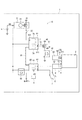
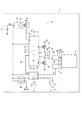
本発明の第1実施形態による制御装置、および、これを適用した車両を図1に示す。
車両1は、内燃機関としてのエンジン2、バッテリ5、および、制御装置10等を備えている。
Hereinafter, a plurality of embodiments of the present invention will be described with reference to the drawings. Note that, in a plurality of embodiments, substantially the same components are denoted by the same reference numerals, and description thereof is omitted.
(First embodiment)
FIG. 1 shows a control device according to a first embodiment of the present invention and a vehicle to which the control device is applied.
The
エンジン2は、例えばガソリンを燃料として駆動する4気筒のガソリンエンジンである。エンジン2は、駆動軸3からトルクを出力する。駆動軸3からのトルクにより、図示しない車輪が回転し、車両1が走行する。駆動軸3には、駆動軸3とともに回転可能なリングギア4が設けられている。
バッテリ5は、例えば鉛蓄電池であり、車両1に設けられた各種機器等に電力を供給する。
The
The
制御装置10は、プッシュスタータ21、インヒビタスイッチ23、スタータ30、リレー40、リレー41、高電位側ドライバ51、アイドルストップECU70、エンジンECU80等を備えている。
The
制御装置10は、車両1の各部に設けられたセンサからの信号等に基づき、エンジン2を制御可能である。特に、本実施形態による制御装置10は、エンジン2の停止の条件である自動停止条件が成立したとき、エンジン2を自動で停止させる、いわゆるアイドルストップ機能を備えている。
バッテリ5の高電位側端子+BBは、プッシュスタータ21、リレー40、アイドルストップECU70、エンジンECU80に接続されている。
The
The high potential side terminal + BB of the
アイドルストップECU70およびエンジンECU80は、それぞれ、CPU、ROM、RAM、I/O等を有する小型のコンピュータであり、車両1の各部に設けられたセンサからの信号等に基づき、ROMまたはRAMに格納されたプログラムに従い演算を行い、車両1のエンジン2の作動を制御する。アイドルストップECU70およびエンジンECU80は、ROMまたはRAMである半導体メモリ等、非遷移的実体的記録媒体に格納されたプログラムを実行する。このプログラムが実行されることで、プログラムに対応する方法が実行される。
The
本実施形態では、アイドルストップECU70は、筐体61に収容されており、入力部601および出力部611等を有している。エンジンECU80は、筐体62に収容されている。ここで、筐体61、62は、それぞれ、特許請求の範囲における「第1筐体」、「第2筐体」に対応している。
アイドルストップECU70とエンジンECU80とは、信号線65により接続されている。信号線65には、例えばCAN(Controller Area Network)規格に準じた信号が流れる。
In the present embodiment, the
The
リレー40は、例えばメカリレーであり、コイルおよび可動接点を有している。エンジンECU80は、イグニッション電圧が印加され起動すると、リレー40のコイルに通電する。リレー40は、コイルに通電されることにより可動接点がオン(通電)状態になり、バッテリ5の高電位側端子+BBから、制御装置10の各部位の高電位側端子+Bへの通電を許容する。
The
プッシュスタータ21は、ボタン22を有している。プッシュスタータ21は、一方側が高電位側端子+Bに接続し、他方側がアイドルストップECU70の入力部601に接続している。インヒビタスイッチ23は、プッシュスタータ21とアイドルストップECU70との間に設けられている。インヒビタスイッチ23は、所定条件のとき、例えば車両1のセレクタレバーがPまたはNポジションにあるときに限りオン状態となり、プッシュスタータ21とアイドルストップECU70との間の信号の伝送を許容する。インヒビタスイッチ23は、例えばセレクタレバーがPまたはN以外のポジションにあるときオフ状態となり、プッシュスタータ21とアイドルストップECU70との間の信号の伝送を遮断する。ここで、プッシュスタータ21は、特許請求の範囲における「初回始動意思検出部」に対応している。また、インヒビタスイッチ23は、特許請求の範囲における「信号伝送許容部」に対応している。
The
例えばセレクタレバーがPポジションで停車中の車両1において、運転者がエンジン2を始動させるため、ボタン22を押下すると、高電位側端子+Bからプッシュスタータ21およびインヒビタスイッチ23を経由してアイドルストップECU70の入力部601にバッテリ電圧(本実施形態では、例えば12V)が印加される。すなわち、プッシュスタータ21は、運転者によるエンジン2の初回の始動意思を検出し、前記初回の始動意思に対応する信号である「初回始動信号」をアイドルストップECU70に伝送する。
図2に示すように、スタータ30は、モータ31、ピニオンギア32、通電部33、押し出し部材34、ソレノイド35等を有している。スタータ30は、エンジン2のリングギア4の近傍に設けられる。
モータ31は、例えばブラシ付きモータであって、モータ軸311を有している。モータ31は、通電されると、モータ軸311からトルクを出力する。
ピニオンギア32は、モータ軸311の軸方向に相対移動可能、かつ、モータ軸311と一体に回転可能に設けられている。
通電部33には、バッテリ5の高電位側端子+BBが接続され、バッテリ電圧が印加されている。
押し出し部材34は、ピニオンギア32の通電部33側に設けられている。
For example, in the
As shown in FIG. 2, the
The
The
The
The pushing
ソレノイド35は、コア351、コイル352を有している。コア351は、押し出し部材34に接するように押し出し部材34の通電部33側に設けられている。ソレノイド35は、コイル352に通電されると、コア351が通電部33側に移動する。コア351が通電部33側に移動すると、押し出し部材34が回動し、ピニオンギア32は、リングギア4に噛み合うよう、リングギア4に向けて押し出される。コア351がさらに通電部33側に移動すると、コア351は、通電部33に当接する。コア351が通電部33に当接すると、モータ31に通電される。モータ31に通電されると、モータ軸311からトルクが出力され、リングギア4に噛み合っているピニオンギア32が回転する。これにより、駆動軸3が回転する。このとき、エンジンECU80は、図示しない燃料噴射弁からエンジン2に燃料が噴射供給されるよう燃料噴射弁の作動を制御する。その結果、エンジン2が始動する。ここで、スタータ30は、特許請求の範囲における「始動デバイス」に対応している。
リレー41は、リレー40と同様、メカリレーである。リレー41は、可動接点の高電位側端子+Bとは反対側がスタータ30のソレノイド35のコイル352に接続している。
高電位側ドライバ51は、リレー41に対し高電位側に設けられている。高電位側ドライバ51は、例えばp−MOS等のスイッチング素子である。
The
The
The high
高電位側ドライバ51は、ソースが高電位側端子+Bに接続し、ドレインがリレー41のコイルに接続し、ゲートがアイドルストップECU70の出力部611に接続している。なお、リレー41のコイルの高電位側ドライバ51とは反対側は、グランドに接続されている。出力部611から高電位側ドライバ51にON信号が出力されると、高電位側ドライバ51はオン状態となり、電流が高電位側端子+Bから高電位側ドライバ51およびリレー41を経由してグランドに流れる。すなわち、リレー41のコイルに通電される。リレー41は、通電されると、高電位側端子+Bとソレノイド35との間の通電を許容する。これにより、コア351が通電部33側に移動し、ピニオンギア32がリングギア4に噛み合うとともに、モータ31が回転し、駆動軸3が回転する。その結果、エンジン2が始動する。以下、アイドルストップECU70から出力部611を経由して高電位側ドライバ51に対し出力される信号を、適宜、「始動用信号」とよぶ。
エンジンECU80には、アクセルペダル6およびブレーキペダル7が接続されている。
The high
An accelerator pedal 6 and a
アクセルペダル6は、車両1の運転者により踏み込まれ、踏み込み量に対応する信号をエンジンECU80に伝送する。エンジンECU80は、アクセルペダル6からの信号に基づき、アクセルペダル6の踏み込みの有無(ON、OFF)、および、アクセルペダル6の踏み込み量を検知することができる。エンジンECU80は、検知したアクセルペダル6の踏み込み量等に基づき、図示しないスロットルバルブの開度や燃料噴射弁からの燃料の噴射量等を制御し、エンジン2の作動を制御する。一般に、アクセルペダル6の踏み込み量が大きいとき、車両1は加速する。
The accelerator pedal 6 is depressed by the driver of the
ブレーキペダル7は、車両1の運転者により踏み込まれ、踏み込み量に対応する信号をエンジンECU80に伝送する。エンジンECU80は、ブレーキペダル7からの信号に基づき、ブレーキペダル7の踏み込みの有無(ON、OFF)、および、ブレーキペダル7の踏み込み量を検知することができる。ブレーキペダル7が踏み込まれると、図示しないパッドが車輪に押し付けられ、車輪の回転が減速する。これにより、車両1は減速する。
The
エンジン2には、クランク角センサ8が設けられている。クランク角センサ8は、リングギア4の回転に対応する信号をエンジンECU80に伝送する。エンジンECU80は、クランク角センサ8からの信号に基づき、駆動軸3の回転数、すなわち、エンジン2の回転数を検知することができる。
The
車両1の車輪の近傍には、車速センサ9が設けられている。車速センサ9は、車輪の回転に対応する信号をエンジンECU80に伝送する。エンジンECU80は、車速センサ9からの信号に基づき、車両1の車速を検知することができる。
アイドルストップECU70は、概念的な機能部として、自動停止制御部71、始動制御部72、始動完了判定部73、自動停止許可部74を備えている。
エンジンECU80は、概念的な機能部として、車両状態判定部81、持続運転判定部82を備えている。
ここで、本発明における「持続運転」とは、燃料の燃焼現象で発生するエネルギーのみでエンジン2が回転し続けることを意味する。
A vehicle speed sensor 9 is provided in the vicinity of the wheel of the
The
The
Here, “sustained operation” in the present invention means that the
車両状態判定部81は、車速センサ9からの信号に基づき、車両1が加速状態、惰性走行状態、減速状態、停車状態のいずれの状態であるかを判定可能である。車両状態判定部81は、判定した結果に対応する信号を、信号線65を経由してアイドルストップECU70の自動停止制御部71に伝送する。
Based on a signal from the vehicle speed sensor 9, the vehicle
持続運転判定部82は、クランク角センサ8からの信号に基づき、エンジン2が持続運転している状態である持続運転状態か否かを判定する。具体的には、持続運転判定部82は、クランク角センサ8からの信号に基づき、エンジン2の回転数が所定の回転数を超えたと判断したとき、「エンジン2は持続運転状態である」と判定する。持続運転判定部82は、判定した結果に対応する信号を、信号線65を経由してアイドルストップECU70の始動完了判定部73に伝送する。
Based on the signal from the
自動停止制御部71は、車両状態判定部81により車両1が惰性走行状態、減速状態または停車状態のいずれかの状態であると判定し、かつ、エンジン2の停止の条件である自動停止条件が成立したとき、エンジン2を制御することによりエンジン2を自動で停止させることが可能である。ここで、「惰性走行状態」とは、車両1が惰性で略一定の速度で走行している状態、すなわち、コースティング走行状態のことである。また、「減速状態」とは、車両1の車速が徐々に低下している状態のことである。また、「停車状態」とは、車両1が停車している状態、すなわち、車両1の車速がゼロの状態のことである。
The automatic
例えば、自動停止制御部71は、車両状態判定部81により車両1が惰性走行状態であると判定し、かつ、「車両1の車速が50km/h以上で、かつ、アクセルペダル6の踏み込みが解除されている(OFF)とき」、自動停止条件が成立したと判定し、判定した結果に対応する信号を、信号線65を経由してエンジンECU80に伝送する。エンジンECU80は、アイドルストップECU70からの信号に基づき、燃料噴射弁からの燃料の噴射を停止する。これにより、エンジン2が自動で停止する。なお、本実施形態では、このとき、エンジンECU80は、エンジン2とトランスミッションとの接続を解除する。これにより、惰性走行時のエンジン2に対する回転抵抗を低減し、さらなる燃費向上を図ることができる。
For example, the automatic
また、例えば、自動停止制御部71は、車両状態判定部81により車両1が減速状態または停車状態であると判定し、かつ、「車両1の車速が10km/h以下で、かつ、ブレーキペダル7が踏み込まれている(ON)とき」、自動停止条件が成立したと判定し、判定した結果に対応する信号を、信号線65を経由してエンジンECU80に伝送する。これにより、エンジン2が自動で停止する。
Further, for example, the automatic
始動制御部72は、プッシュスタータ21から「初回始動意思信号」を受信したとき、および、エンジン2の始動の条件である自動始動条件が成立したとき、スタータ30への通電を制御し、スタータ30を駆動することによりエンジン2を始動させることが可能である。
The
例えば、セレクタレバーがPポジションで停車中の車両1において、運転者がエンジン2を始動させるため、ボタン22を押下すると、プッシュスタータ21は、「初回始動意思信号(ON)」をアイドルストップECU70の始動制御部72に伝送する。始動制御部72は、プッシュスタータ21からの信号に基づき、出力部611から高電位側ドライバ51に対し「始動用信号(ON)」を出力する。これにより、高電位側ドライバ51がオン状態になり、スタータ30に通電され、スタータ30が駆動し、エンジン2が始動する。このときのエンジン2の始動は、初回の始動である。
For example, in the
このように、始動制御部72は、プッシュスタータ21から「初回始動意思信号(ON)」を受信したとき、スタータ30への通電を制御し、スタータ30を駆動することによりエンジン2を始動させることが可能である。
As described above, when the
また、例えば、車両1が惰性走行状態または減速状態のときに自動停止制御部71によりエンジン2が自動で停止された後、車両1が走行している状態で「アクセルペダル6が踏み込まれた(OFF→ON)とき」または「ブレーキペダル7の踏み込みが解除された(ON→OFF)とき」、始動制御部72は、自動始動条件が成立したと判定し、出力部611から高電位側ドライバ51に対し「始動用信号」を出力する。これにより、スタータ30が駆動し、エンジン2が自動で始動する。
Further, for example, after the
また、例えば、車両1が惰性走行状態、減速状態または停車状態のときに自動停止制御部71によりエンジン2が自動で停止された後、車両1が停車している状態で「ブレーキペダル7の踏み込みが解除された(ON→OFF)とき」、始動制御部72は、自動始動条件が成立したと判定し、出力部611から高電位側ドライバ51に対し「始動用信号」を出力する。これにより、スタータ30が駆動し、エンジン2が自動で始動する。
このように、始動制御部72は、自動始動条件が成立したとき、スタータ30への通電を制御し、スタータ30を駆動することによりエンジン2を自動で始動させることが可能である。
Further, for example, when the
In this way, the
始動完了判定部73は、エンジン2の始動が完了したか否かを判定可能である。上述のように、持続運転判定部82は、エンジン2の回転数が所定の回転数を超えたと判断し、「エンジン2は持続運転状態である」と判定したとき、判定した結果に対応する信号を、信号線65を経由してアイドルストップECU70の始動完了判定部73に伝送する。始動完了判定部73は、持続運転判定部82からの信号に基づき、エンジン2の始動が完了したか否かを判定する。すなわち、始動完了判定部73は、持続運転判定部82により「エンジン2は持続運転状態である」と判定したとき、「エンジン2の始動が完了した」と判定する。ここで、「エンジン2の始動が完了した」とは、エンジン2が完爆したことを意味する。
The start
自動停止許可部74は、始動制御部72がプッシュスタータ21から「初回始動意思信号」を受信しエンジン2を始動させるとき、始動完了判定部73により「エンジン2の始動が完了した」と判定した場合、以後、自動停止制御部71によるエンジン2の停止を許可する。一方、自動停止許可部74は、始動制御部72がプッシュスタータ21から「初回始動意思信号」を受信しエンジン2を始動させるとき、始動完了判定部73により「エンジン2の始動が完了した」と判定されなかった場合、以後、自動停止制御部71によるエンジン2の停止を禁止する。これにより、「始動制御部72が上手く作動しない状態のときに、自動停止制御部71によりエンジン2が自動で停止され、その後の始動制御部72によるエンジン2の自動始動が失敗するといった事態」を防ぐことができる。
When the
本実施形態では、始動制御部72は、エンジン2を始動させるとき、始動完了判定部73により「エンジン2の始動が完了した」と判定した場合、高電位側ドライバ51への「始動用信号(ON)」の出力を停止することにより、スタータ30への通電を停止する。これにより、エンジン2完爆後のスタータ30による電力消費を止めることができる。
In the present embodiment, when starting the
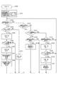
次に、本実施形態の制御装置10によるエンジン2の制御について、図3に基づき説明する。
制御装置10は、図3に示す一連の処理S100を実行することにより、エンジン2を制御する。S100は、エンジンECU80およびアイドルストップECU70にイグニッション電圧が印加されエンジンECU80およびアイドルストップECU70が起動すると、開始される。
Next, control of the
The
S101では、アイドルストップECU70は、各種フラグをリセットする。
具体的には、エンジン2の初回の始動が完了しているか否かを示す初回始動完了フラグF0に0を設定する。なお、F0は、F0=0のとき、「エンジン2の初回の始動は完了していないこと」を示し、F0=1のとき、「エンジン2の初回の始動は完了していること」を示す。
In S101, the
Specifically, the initial start completion flag F0 indicating whether the initial start of the
また、自動停止制御部71によりエンジン2が自動で停止しているか否かを示す自動停止中フラグF1に0を設定する。なお、F1は、F1=0のとき、「エンジン2は自動停止制御部71により自動で停止していないこと」を示し、F1=1のとき、「エンジン2は自動停止制御部71により自動で停止していること」を示す。
Further, the automatic
また、自動停止制御部71によるエンジン2の停止を禁止するか否かを示す自動停止禁止フラグF2に1を設定する。なお、F2は、F2=0のとき、「自動停止制御部71によるエンジン2の停止を禁止しない、すなわち、許可すること」を示し、F2=1のとき、「自動停止制御部71によるエンジン2の停止を禁止すること」を示す。
S101の後、処理はS102へ移行する。
Further, 1 is set to the automatic stop prohibition flag F2 indicating whether or not the stop of the
After S101, the process proceeds to S102.
S102では、アイドルストップECU70は、エンジン2の初回の始動が完了しているか否かを判断する。具体的には、F0の値に基づき判断する。F0=0で「エンジン2の初回の始動は完了していない」と判断した場合(S102:NO)、処理はS103へ移行する。一方、F0=1で「エンジン2の初回の始動は完了している」と判断した場合(S102:YES)、処理はS110へ移行する。
In S102, the
S103では、アイドルストップECU70は、運転者によりボタン22が押下されスタートスイッチがオンされたか否かを判断する。具体的には、始動制御部72がプッシュスタータ21から「初回始動意思信号(ON)」を受信したか否かを判断する。「初回始動意思信号」を受信したと判断した場合(S103:YES)、処理はS104へ移行する。一方、「初回始動意思信号」を受信していないと判断した場合(S103:NO)、処理はS111へ移行する。
In S103, the
S104では、アイドルストップECU70は、スタータ30をオンにする。具体的には、始動制御部72は、出力部611から高電位側ドライバ51に対し「始動用信号(ON)」を出力し、スタータ30を駆動させる。S104の後、処理はS105へ移行する。
In S104, the
S105では、アイドルストップECU70は、エンジン2の回転数が所定の回転数、すなわち、完爆時の回転数を超えたか否かを判断する。具体的には、アイドルストップECU70は、エンジンECU80の持続運転判定部82からの信号に基づき、エンジン2の回転数が所定の回転数を超えたか否かを判断する。エンジン2の回転数は所定の回転数を超えたと判断した場合(S105:YES)、処理はS106へ移行する。一方、エンジン2の回転数は所定の回転数を超えていないと判断した場合(S105:NO)、処理はS102へ戻る。
In S105, the
S106では、アイドルストップECU70は、スタータ30をオフにする。具体的には、始動制御部72は、出力部611から高電位側ドライバ51への「始動用信号(ON)」の出力を停止(OFF)し、スタータ30の駆動を停止させる。S106の後、処理はS107へ移行する。
In S106, the
S107では、アイドルストップECU70は、エンジン2の初回の始動が完了しているか否かを示す初回始動完了フラグF0に1を設定する。S107の後、処理はS108へ移行する。
S108では、アイドルストップECU70は、自動停止制御部71によるエンジン2の停止を禁止するか否かを示す自動停止禁止フラグF2に0を設定する。これにより、F2は、「自動停止制御部71によるエンジン2の停止を禁止しない、すなわち、許可すること」を示す。S108の後、処理はS102へ戻る。
In S107, the
In S108, the
S110では、アイドルストップECU70は、自動停止制御部71によるエンジン2の停止が禁止されているか否かを判断する。具体的には、F2の値に基づき判断する。F2=1で「自動停止制御部71によるエンジン2の停止が禁止されている」と判断した場合(S110:YES)、処理はS102へ戻る。一方、F2=0で「自動停止制御部71によるエンジン2の停止は禁止されていない」と判断した場合(S110:NO)、処理はS121へ移行する。
S111では、アイドルストップECU70は、スタータ30をオフにする。具体的には、始動制御部72は、出力部611から高電位側ドライバ51への「始動用信号(ON)」の出力を停止(OFF)し、スタータ30の駆動を停止した状態にする。S111の後、処理はS102へ戻る。
In S110, the
In S111, the
S121では、アイドルストップECU70は、自動停止制御部71によりエンジン2が自動で停止しているか否かを判断する。具体的には、F1の値に基づき判断する。F1=0で「エンジン2は自動停止制御部71により自動で停止していない」と判断した場合(S121:NO)、処理はS122へ移行する。一方、F1=1で「エンジン2は自動停止制御部71により自動で停止している」と判断した場合(S121:YES)、処理はS131へ移行する。
In S121, the
S122では、アイドルストップECU70の自動停止制御部71は、自動停止条件が成立したか否かを判断する。自動停止条件が成立したと判断した場合(S122:YES)、処理はS123へ移行する。なお、この場合、自動停止制御部71は、エンジンECU80を経由してエンジン2を自動で停止させる。一方、自動停止条件は成立していないと判断した場合(S122:NO)、処理はS102へ戻る。
S123では、アイドルストップECU70は、自動停止制御部71によりエンジン2が自動で停止しているか否かを示すフラグF1に1を設定する。S123の後、処理はS102へ戻る。
In S122, the automatic
In S123, the
S131では、アイドルストップECU70の始動制御部72は、自動始動条件が成立したか否かを判断する。自動始動条件が成立したと判断した場合(S131:YES)、処理はS132へ移行する。一方、自動始動条件は成立していないと判断した場合(S131:NO)、処理はS102へ戻る。
In S131, the
S132では、アイドルストップECU70は、スタータ30をオンにする。具体的には、始動制御部72は、出力部611から高電位側ドライバ51に対し「始動用信号(ON)」を出力し、スタータ30を駆動させる。S132の後、処理はS133へ移行する。
In S132, the
S133では、アイドルストップECU70は、エンジン2の回転数が所定の回転数、すなわち、完爆時の回転数を超えたか否かを判断する。具体的には、アイドルストップECU70は、エンジンECU80の持続運転判定部82からの信号に基づき、エンジン2の回転数が所定の回転数を超えたか否かを判断する。エンジン2の回転数は所定の回転数を超えたと判断した場合(S133:YES)、処理はS134へ移行する。一方、エンジン2の回転数は所定の回転数を超えていないと判断した場合(S133:NO)、処理はS102へ戻る。
In S133, the
S134では、アイドルストップECU70は、スタータ30をオフにする。具体的には、始動制御部72は、出力部611から高電位側ドライバ51への「始動用信号(ON)」の出力を停止(OFF)し、スタータ30の駆動を停止させる。S134の後、処理はS135へ移行する。
S135では、アイドルストップECU70は、自動停止制御部71によりエンジン2が自動で停止しているか否かを示すフラグF1に0を設定する。S135の後、処理はS102へ戻る。
このように、処理S100は、エンジンECU80およびアイドルストップECU70が起動すると開始され、エンジンECU80およびアイドルストップECU70が停止するまで実行が継続される。
In S134, the
In S135, the
Thus, the process S100 is started when the
次に、本実施形態の制御装置10によるエンジン2の制御の例を、図4、5、6に基づき説明する。
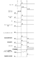
1つ目の例を図4に示す。
時刻t1で、運転者がプッシュスタータ21のボタン22を押下すると、アクセサリ電源がオンになる。
時刻t2で、運転者がプッシュスタータ21のボタン22を押下すると、イグニッション電源がオンになる。これにより、エンジンECU80およびアイドルストップECU70が起動し、高電位側端子+Bにバッテリ電圧が印加される。
Next, an example of control of the
A first example is shown in FIG.
When the driver presses the
When the driver presses the
時刻t3の前に運転者がブレーキペダル7を踏み込み(OFF→ON)、時刻t3で運転者がプッシュスタータ21のボタン22を押下すると、プッシュスタータ21から「初回始動意思信号(ON)」が始動制御部72に伝送される。これにより、始動制御部72から高電位側ドライバ51に対し「始動用信号(ON)」が出力される。その結果、高電位側ドライバ51がオン状態になり、スタータ30に通電され、スタータ30が駆動(ON)する。
Before the time t3, the driver depresses the brake pedal 7 (OFF → ON), and when the driver presses the
エンジン2の回転数が上昇し、時刻t4でエンジン2の回転数が所定の回転数を超えると、持続運転判定部82は、「エンジン2は持続運転状態である(OK)」と判定する。そのため、始動完了判定部73は、「エンジン2の始動が完了した」と判定する。これにより、アイドルストップECU70への「初回始動意思信号(ON)」の伝送が停止し(OFF)、高電位側ドライバ51への「始動用信号(ON)」の出力が停止する。その結果、スタータ30の駆動が停止(OFF)する。
When the rotational speed of the
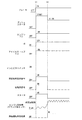
2つ目の例を図5に示す。
時刻t1で、運転者がプッシュスタータ21のボタン22を押下すると、アクセサリ電源がオンになる。
時刻t2の前に運転者がブレーキペダル7を踏み込み(OFF→ON)、時刻t2で運転者がプッシュスタータ21のボタン22を押下すると、イグニッション電源がオンになり、エンジンECU80およびアイドルストップECU70が起動し、高電位側端子+Bにバッテリ電圧が印加される。また、プッシュスタータ21から「初回始動意思信号(ON)」が始動制御部72に伝送される。これにより、始動制御部72から高電位側ドライバ51に対し「始動用信号(ON)」が出力される。その結果、高電位側ドライバ51がオン状態になり、スタータ30に通電され、スタータ30が駆動する。
A second example is shown in FIG.
When the driver presses the
Before the time t2, the driver depresses the brake pedal 7 (OFF → ON). When the driver presses the
エンジン2の回転数が上昇し、時刻t3でエンジン2の回転数が所定の回転数を超えると、持続運転判定部82は、「エンジン2は持続運転状態である(OK)」と判定する。そのため、始動完了判定部73は、「エンジン2の始動が完了した」と判定する。これにより、アイドルストップECU70への「初回始動意思信号(ON)」の伝送が停止し(OFF)、高電位側ドライバ51への「始動用信号(ON)」の出力が停止する。その結果、スタータ30の駆動が停止する。
When the rotational speed of the
3つ目の例を図6に示す。
時刻t1の前に運転者がブレーキペダル7を踏み込み(OFF→ON)、時刻t1で運転者がプッシュスタータ21のボタン22を押下すると、イグニッション電源がオンになり、エンジンECU80およびアイドルストップECU70が起動し、高電位側端子+Bにバッテリ電圧が印加される。また、プッシュスタータ21から「初回始動意思信号(ON)」が始動制御部72に伝送される。これにより、始動制御部72から高電位側ドライバ51に対し「始動用信号(ON)」が出力される。その結果、高電位側ドライバ51がオン状態になり、スタータ30に通電され、スタータ30が駆動する。
A third example is shown in FIG.
Before the time t1, the driver depresses the brake pedal 7 (OFF → ON). When the driver presses the
エンジン2の回転数が上昇し、時刻t2でエンジン2の回転数が所定の回転数を超えると、持続運転判定部82は、「エンジン2は持続運転状態である(OK)」と判定する。そのため、始動完了判定部73は、「エンジン2の始動が完了した」と判定する。これにより、アイドルストップECU70への「初回始動意思信号(ON)」の伝送が停止し(OFF)、高電位側ドライバ51への「始動用信号(ON)」の出力が停止する。その結果、スタータ30の駆動が停止する。
When the rotational speed of the
以上説明したように、(1)本実施形態は、エンジン2、運転者によるエンジン2の初回の始動意思を検出し前記初回の始動意思に対応する信号である初回始動意思信号を出力可能なプッシュスタータ21、および、通電により駆動しエンジン2の駆動軸3を回転させエンジン2を始動させることが可能なスタータ30を備える車両1に設けられ、エンジン2を制御する制御装置10であって、自動停止制御部71と始動制御部72と始動完了判定部73と自動停止許可部74とを備える。
自動停止制御部71は、エンジン2の停止の条件である自動停止条件が成立したとき、エンジン2を制御することによりエンジン2を自動で停止させることが可能である。
As described above, (1) this embodiment is a push capable of detecting an initial start intention of the
The automatic
始動制御部72は、プッシュスタータ21から初回始動意思信号を受信したとき、または、エンジン2の始動の条件である自動始動条件が成立したとき、スタータ30への通電を制御し、スタータ30を駆動することによりエンジン2を始動させることが可能である。
始動完了判定部73は、エンジン2の始動が完了したか否かを判定可能である。
The
The start
自動停止許可部74は、始動制御部72がプッシュスタータ21から初回始動意思信号を受信しエンジン2を始動させるとき、始動完了判定部73により「エンジン2の始動が完了した」と判定した場合、自動停止制御部71によるエンジン2の停止を許可する。
When the
このように、本実施形態では、エンジン2の初回の始動時、すなわち、車両1の停車中に、始動制御部72によるエンジン2の始動が可能か否かを確認することができる。そして、始動制御部72によるエンジン2の始動が可能であることを確認した場合、自動停止制御部71によるエンジン2の停止を許可する。そのため、車両1の走行開始後、例えば車両1が停車状態になる前に惰性走行状態や減速状態になり、かつ、自動停止条件が成立した場合、自動停止制御部71によりエンジン2を停止させることができる。これにより、上述の従来技術による制御装置と比べ、エンジン2を自動で停止させる機会を増大させることができる。したがって、さらなる燃費の向上を図ることができる。
Thus, in the present embodiment, it is possible to confirm whether or not the
また、(2)本実施形態は、車両1の状態を判定可能な車両状態判定部81をさらに備えている。自動停止制御部71は、車両状態判定部81により車両1が惰性走行状態、減速状態または停車状態のいずれかの状態であると判定し、かつ、自動停止条件が成立したとき、エンジン2を停止させることが可能である。このように、本実施形態では、車両1が惰性走行状態または減速状態のときでも、自動停止制御部71によりエンジン2を停止させることができる。
Moreover, (2) this embodiment is further provided with the vehicle
また、(3)本実施形態は、エンジン2が持続運転している状態である持続運転状態か否かを判定する持続運転判定部82をさらに備えている。始動完了判定部73は、持続運転判定部82により「エンジン2は持続運転状態である」と判定したとき、「エンジン2の始動が完了した」と判定する。
また、(4)本実施形態では、持続運転判定部82は、エンジン2の回転数が所定の回転数を超えたと判断したとき、「エンジン2は持続運転状態である」と判定する。
In addition, (3) the present embodiment further includes a continuous
Further, (4) in the present embodiment, the continuous
また、(5)本実施形態は、少なくとも始動完了判定部73を収容する筐体61、少なくとも持続運転判定部82を収容する筐体62、および、始動完了判定部73と持続運転判定部82とを接続し信号が流れる信号線65をさらに備えている。持続運転判定部82は、判定した結果に対応する信号を、信号線65を経由して始動完了判定部73に伝送する。このように、アイドルストップECU70側の筐体61に持続運転判定部82を設けなくても、アイドルストップECU70は、信号線65を経由して持続運転判定部82による判定結果を知ることができる。したがって、アイドルストップECU70を小型化できる。
(5) In the present embodiment, the
また、(6)本実施形態では、始動制御部72は、エンジン2を始動させるとき、始動完了判定部73により「エンジン2の始動が完了した」と判定した場合、スタータ30への通電を停止する。これにより、エンジン2完爆後のスタータ30による電力消費を止めることができる。したがって、スタータ30による電力消費を抑えることができる。
(6) In the present embodiment, when starting the
また、(8)本実施形態は、プッシュスタータ21と始動制御部72との間に設けられ、所定条件のときに限りプッシュスタータ21と始動制御部72との間の信号の伝送を許容するインヒビタスイッチ23をさらに備えている。
また、(9)本実施形態は、初回始動意思検出部としてのプッシュスタータ21をさらに備えている。プッシュスタータ21は、運転者が押下可能なボタン22を有している。
(8) In the present embodiment, an inhibitor is provided between the
Further, (9) the present embodiment further includes a
(第2実施形態)
本発明の第2実施形態による制御装置10を図7に示す。第2実施形態は、初回始動意思検出部が第1実施形態と異なる。
第2実施形態では、制御装置10は、初回始動意思検出部として、キースタータ25を備えている。
キースタータ25は、穴部26、端子251、ACC接点252、IG接点253、START接点254を有している。
(Second Embodiment)
FIG. 7 shows a
In the second embodiment, the
The
穴部26には、キー27を差し込み可能である。穴部26は、キー27を差し込んだ状態で回転させると回転可能である。端子251は、穴部26と一体に回転可能に設けられている。端子251の一端は、バッテリ5の高電位側端子+BBに接続している。
A key 27 can be inserted into the
ACC接点252、IG接点253およびSTART接点254は、それぞれ、回転する端子251の他端に接触可能な位置に設けられている。ACC接点252は、アクセサリ電源の高電位側に接続している。IG接点253は、イグニッション電源の高電位側に接続している。START接点254は、インヒビタスイッチ23に接続している。
The
端子251の他端は、ACC接点252とIG接点253と、または、IG接点253とSTART接点254とを接続可能な程度の長さに形成されている。これにより、運転者が穴部26にキー27を差し込み回転させると、端子251の他端は、最初、ACC接点252のみに接触する。これにより、アクセサリ電源がオンになる。キー27をさらに回転させると、端子251の他端は、IG接点253およびACC接点252に接触した状態となる。これにより、アクセサリ電源およびイグニッション電源がオンになる。キー27をさらに回転させると、端子251の他端は、ACC接点252から離れ、START接点254およびIG接点253に接触した状態となる。これにより、アクセサリ電源がオフになるとともに、イグニッション電源はオンのままで、インヒビタスイッチ23にバッテリ電圧が印加される。ここで、運転者がキー27から手を放すと、図示しない付勢部材により穴部26および端子251が逆向きに回転する。これにより、端子251の他端は、ACC接点252とIG接点253とを接続した状態となる。
The other end of the terminal 251 is formed to such a length that the
本実施形態では、例えばセレクタレバーがPポジションで停車中の車両1において、運転者がエンジン2を始動させるため、穴部26にキー27を差し込み、キー27をSTART位置まで回転させると、高電位側端子+Bからキースタータ25およびインヒビタスイッチ23を経由してアイドルストップECU70の入力部601にバッテリ電圧が印加される。すなわち、キースタータ25は、運転者によるエンジン2の初回の始動意思を検出し、「初回始動意思信号」をアイドルストップECU70に伝送する。
In the present embodiment, for example, in the
また、本実施形態では、始動制御部72は、少なくとも運転者がキー27をSTART位置に留めている間、すなわち、キースタータ25から「初回始動意思信号」を受信している間、スタータ30への通電を継続する。
上述した点以外の点は、第1実施形態と同様である。
Further, in the present embodiment, the
Points other than those described above are the same as in the first embodiment.
以上説明したように、(10)本実施形態は、初回始動意思検出部としてのキースタータ25をさらに備えている。キースタータ25は、キー27を差し込み可能な穴部26を有している。
また、(7)始動制御部72は、少なくともキースタータ25から「初回始動意思信号」を受信している間、スタータ30への通電を継続する。そのため、「運転者がキー27をSTART位置に留めているにもかかわらずスタータ30が停止する」という違和感の発生を低減することができる。
As described above, (10) the present embodiment further includes the
(7) The
(第3実施形態)
本発明の第3実施形態による制御装置10を図8に示す。第3実施形態は、制御装置10を構成する部材数が多い点等で第1実施形態と異なる。
第3実施形態では、制御装置10は、低電位側ドライバ52をさらに備えている。
(Third embodiment)
A
In the third embodiment, the
低電位側ドライバ52は、例えばn−MOS等のスイッチング素子である。低電位側ドライバ52は、リレー41に対し低電位側に設けられている。低電位側ドライバ52は、ドレインがリレー41のコイルに接続し、ソースがグランドに接続し、ゲートがアイドルストップECU70の出力部612に接続している。
The low
本実施形態では、始動制御部72は、プッシュスタータ21から「初回始動意思信号(ON)」を受信したとき、または、自動始動条件が成立したとき、出力部611から高電位側ドライバ51に対し「始動用信号(ON)」を出力するとともに、出力部612から低電位側ドライバ52に対し「始動用信号(ON)」を出力する。これにより、高電位側ドライバ51および低電位側ドライバ52がオン状態となり、電流が高電位側端子+Bから高電位側ドライバ51、リレー41および低電位側ドライバ52を経由してグランドに流れる。その結果、スタータ30が駆動し、エンジン2が始動する。
上述した点以外の点は、第1実施形態と同様である。
In the present embodiment, the
Points other than those described above are the same as in the first embodiment.
以上説明したように、(11)本実施形態は、リレー41、高電位側ドライバ51および低電位側ドライバ52を備えている。リレー41は、通電されることによりスタータ30への通電を許容し、通電が停止されることによりスタータ30への通電を遮断可能である。高電位側ドライバ51は、リレー41に対し高電位側に設けられ、信号の入力により、高電位側からリレー41への通電を許容または遮断可能である。低電位側ドライバ52は、リレー41に対し低電位側に設けられ、信号の入力により、リレー41から低電位側への通電を許容または遮断可能である。
As described above, (11) the present embodiment includes the
上記構成により、例えばハーネスの噛み込み等により高電位側ドライバ51または低電位側ドライバ52の一方がオン固着した状態になったとしても、他方に対し信号を出力することにより、リレー41の通電の制御を継続することができる。そのため、制御装置10の信頼性を向上することができる。
With the above configuration, even if one of the high
(第4実施形態)
本発明の第4実施形態による制御装置10を図9に示す。第4実施形態は、制御装置10を構成する部材数が多い点等で第1実施形態と異なる。
第4実施形態では、制御装置10は、バイパス始動部としてのバイパスドライバ55をさらに備えている。
(Fourth embodiment)
A
In the fourth embodiment, the
バイパスドライバ55は、例えばn−MOS等のスイッチング素子である。バイパスドライバ55は、ゲートにON信号が入力されていないとき、ドレインとソースとの間を電気的に接続し、ゲートにON信号が入力されているとき、ドレインとソースとの間を電気的に遮断する。すなわち、バイパスドライバ55は、ノーマリーONタイプのスイッチング素子である。 The bypass driver 55 is a switching element such as an n-MOS, for example. The bypass driver 55 electrically connects the drain and the source when the ON signal is not input to the gate, and electrically connects the drain and the source when the ON signal is input to the gate. Cut off. That is, the bypass driver 55 is a normally ON type switching element.
バイパスドライバ55は、始動制御部72をバイパスするようプッシュスタータ21とスタータ30との間に設けられている。具体的には、バイパスドライバ55は、ドレインがインヒビタスイッチ23と入力部601との間に接続し、ソースが高電位側ドライバ51のゲートと出力部611との間に接続し、ゲートがアイドルストップECU70の出力部631に接続している。
The bypass driver 55 is provided between the
本実施形態では、アイドルストップECU70は、イグニッション電圧が印加されることにより起動すると、始動制御部72が正常なときは、始動制御部72から出力部631を経由してバイパスドライバ55に対しON信号を出力し続ける。これにより、バイパスドライバ55はオフ状態となる。このとき、プッシュスタータ21から「初回始動意思信号(ON)」が出力されると、当該信号は、入力部601を経由して始動制御部72に入力される。これにより、始動制御部72は、出力部611を経由して高電位側ドライバ51に対し「始動用信号(ON)」を出力する。その結果、リレー41に通電され、スタータ30が駆動し、エンジン2が始動する。
In this embodiment, the
一方、始動制御部72が異常なときは、始動制御部72から出力部631を経由してバイパスドライバ55に対しON信号は出力されない。そのため、バイパスドライバ55はオン状態となる。このとき、プッシュスタータ21から「初回始動意思信号(ON)」が出力されると、当該信号が入力部601を経由して始動制御部72に入力されるものの、始動制御部72は異常のため、高電位側ドライバ51に対する「始動用信号(ON)」は出力されない。一方、プッシュスタータ21から出力された「初回始動意思信号(ON)」は、オン状態のバイパスドライバ55を経由して高電位側ドライバ51のゲートに入力される。これにより、リレー41に通電され、スタータ30が駆動し、エンジン2が始動する。
On the other hand, when the
このように、バイパスドライバ55は、始動制御部72をバイパスするようプッシュスタータ21とスタータ30との間に設けられ、プッシュスタータ21から「初回始動意思信号(ON)」を受信したとき、スタータ30への通電を許容し、スタータ30を駆動することによりエンジン2を始動させることが可能である。また、制御装置10は、始動制御部72が正常なとき、バイパスドライバ55によるエンジン2の始動を禁止し、始動制御部72が異常なとき、バイパスドライバ55によるエンジン2の始動を許容する。
また、自動停止許可部74は、バイパスドライバ55によりエンジン2が始動した場合、すなわち、始動制御部72が異常なとき、自動停止制御部71によるエンジン2の停止を禁止する。
As described above, the bypass driver 55 is provided between the
Further, the automatic
また、本実施形態では、アイドルストップECU70は、入力部621を有している。入力部621は、高電位側ドライバ51のドレインとリレー41のコイルとの間に接続している。そのため、高電位側ドライバ51がオン状態になると、バッテリ電圧が入力部621に印加される。以下、入力部621に印加される電圧を、適宜、モニタ信号とよぶ。
In the present embodiment, the
アイドルストップECU70は、例えば、高電位側ドライバ51に対し「始動用信号(ON)」を出力していないにもかかわらず入力部621に「モニタ信号(ON)」が入力された場合、「バイパスドライバ55がオフ状態になっておらず、高電位側ドライバ51に対し始動用信号を出力する前に、プッシュスタータ21からの初回始動意思信号がバイパスドライバ55を経由して高電位側ドライバ51に入力されたこと」を検知することができる。その後、出力部611から「始動用信号(ON)」が出力され、スタータ30の駆動によりエンジン2が始動できた場合、制御装置10は、「始動制御部72は正常である」と判断し、自動停止制御部71によるエンジン2の停止を許容する。一方、出力部611から「始動用信号(ON)」が出力されず、バイパスドライバ55によりエンジン2が始動した場合、制御装置10は、「始動制御部72は異常である」と判断し、自動停止制御部71によるエンジン2の停止を禁止する。
For example, when the “monitor signal (ON)” is input to the
次に、本実施形態の制御装置10によるエンジン2の制御の一例を、図10に基づき説明する。
時刻t1で、運転者がプッシュスタータ21のボタン22を押下すると、アクセサリ電源がオンになる。
Next, an example of control of the
When the driver presses the
時刻t2で、運転者がプッシュスタータ21のボタン22を押下すると、イグニッション電源がオンになる。これにより、エンジンECU80およびアイドルストップECU70が起動し、高電位側端子+Bにバッテリ電圧が印加される。また、アイドルストップECU70は、始動制御部72から出力部631を経由してバイパスドライバ55に対しON信号を出力する。これにより、バイパスドライバ55はオフ状態となる。そのため、バイパスドライバ55によるエンジン2の始動は禁止された状態となる。
When the driver presses the
時刻t3の前に運転者がブレーキペダル7を踏み込み(OFF→ON)、時刻t3で運転者がプッシュスタータ21のボタン22を押下すると、プッシュスタータ21から「初回始動意思信号(ON)」が始動制御部72に伝送される。これにより、始動制御部72から高電位側ドライバ51に対し「始動用信号(ON)」が出力される。その結果、高電位側ドライバ51がオン状態になり、スタータ30に通電され、スタータ30が駆動(ON)する。また、このとき、入力部621には、「モニタ信号(ON)」が入力される。
Before the time t3, the driver depresses the brake pedal 7 (OFF → ON), and when the driver presses the
エンジン2の回転数が上昇し、時刻t4でエンジン2の回転数が所定の回転数を超えると、持続運転判定部82は、「エンジン2は持続運転状態である(OK)」と判定する。そのため、始動完了判定部73は、「エンジン2の始動が完了した」と判定する。これにより、アイドルストップECU70への「初回始動意思信号(ON)」の伝送が停止し(OFF)、高電位側ドライバ51への「始動用信号(ON)」の出力が停止する。その結果、スタータ30の駆動が停止(OFF)する。なお、このとき、入力部621への「モニタ信号」の入力は停止(OFF)する。
When the rotational speed of the
以上説明したように、(15)本実施形態は、バイパスドライバ55をさらに備えている。バイパスドライバ55は、始動制御部72をバイパスするようプッシュスタータ21とスタータ30との間に設けられ、プッシュスタータ21から「初回始動意思信号(ON)」を受信したとき、スタータ30への通電を許容し、スタータ30を駆動することによりエンジン2を始動させることが可能である。また、制御装置10は、始動制御部72が正常なとき、バイパスドライバ55によるエンジン2の始動を禁止し、始動制御部72が異常なとき、バイパスドライバ55によるエンジン2の始動を許容する。これにより、始動制御部72が正常なときは始動制御部72によるエンジン2の初回始動を実施し、始動制御部72が異常なときでも、バイパスドライバ55によりエンジン2の初回始動を実施することができる。よって、制御装置10によるエンジン2の初回始動の信頼性を向上することができる。
As described above, (15) the present embodiment further includes the bypass driver 55. The bypass driver 55 is provided between the
また、(16)本実施形態では、自動停止許可部74は、バイパスドライバ55によりエンジン2が始動した場合、すなわち、始動制御部72が異常なとき、自動停止制御部71によるエンジン2の停止を禁止する。これにより、「自動停止制御部71によるエンジン2の停止後、始動制御部72によるエンジン2の自動始動ができなくなる」といった事態を回避することができる。
(16) In this embodiment, the automatic
(第5実施形態)
本発明の第5実施形態による制御装置10を図11に示す。第5実施形態は、制御装置10を構成する部材数が多い点等で第3、4実施形態と異なる。
第5実施形態では、制御装置10は、低電位側ドライバ52、および、バイパス始動部としてのバイパスドライバ56をさらに備えている。
低電位側ドライバ52は、第3実施形態で説明したものと同様のため、説明を省略する。
バイパスドライバ56は、バイパスドライバ55と同様、例えばn−MOS等のノーマリーONタイプのスイッチング素子である。
(Fifth embodiment)
A
In the fifth embodiment, the
Since the low
Similar to the bypass driver 55, the
バイパスドライバ56は、始動制御部72をバイパスするようプッシュスタータ21とスタータ30との間に設けられている。具体的には、バイパスドライバ56は、ドレインがインヒビタスイッチ23と入力部601との間に接続し、ソースが低電位側ドライバ52のゲートと出力部612との間に接続し、ゲートがアイドルストップECU70の出力部632に接続している。
The
本実施形態では、アイドルストップECU70は、イグニッション電圧が印加されることにより起動すると、始動制御部72が正常なときは、始動制御部72から出力部631、632を経由してバイパスドライバ55、56に対しON信号を出力し続ける。これにより、バイパスドライバ55、56はオフ状態となる。このとき、プッシュスタータ21から「初回始動意思信号(ON)」が出力されると、当該信号は、入力部601を経由して始動制御部72に入力される。これにより、始動制御部72は、出力部611、612を経由して高電位側ドライバ51、低電位側ドライバ52に対し「始動用信号(ON)」を出力する。その結果、リレー41に通電され、スタータ30が駆動し、エンジン2が始動する。
In the present embodiment, when the
一方、始動制御部72が異常なときは、始動制御部72から出力部631、632を経由してバイパスドライバ55、56に対しON信号は出力されない。そのため、バイパスドライバ55、56はオン状態となる。このとき、プッシュスタータ21から「初回始動意思信号(ON)」が出力されると、当該信号が入力部601を経由して始動制御部72に入力されるものの、始動制御部72は異常のため、高電位側ドライバ51、低電位側ドライバ52に対する「始動用信号(ON)」は出力されない。一方、プッシュスタータ21から出力された「初回始動意思信号(ON)」は、オン状態のバイパスドライバ55、56を経由して高電位側ドライバ51、低電位側ドライバ52のゲートに入力される。これにより、リレー41に通電され、スタータ30が駆動し、エンジン2が始動する。
On the other hand, when the
このように、バイパスドライバ55、56は、始動制御部72をバイパスするようプッシュスタータ21とスタータ30との間に設けられ、プッシュスタータ21から「初回始動意思信号(ON)」を受信したとき、スタータ30への通電を許容し、スタータ30を駆動することによりエンジン2を始動させることが可能である。また、制御装置10は、始動制御部72が正常なとき、バイパスドライバ55、56によるエンジン2の始動を禁止し、始動制御部72が異常なとき、バイパスドライバ55、56によるエンジン2の始動を許容する。
また、自動停止許可部74は、バイパスドライバ55、56によりエンジン2が始動した場合、すなわち、始動制御部72が異常なとき、自動停止制御部71によるエンジン2の停止を禁止する。
上述した点以外の点は、第3、4実施形態と同様である。
In this manner, the
Further, the automatic
Points other than those described above are the same as in the third and fourth embodiments.
以上説明したように、本実施形態では、リレー41に対し高電位側ドライバ51および低電位側ドライバ52を設け、高電位側ドライバ51に対しバイパスドライバ55を接続し、低電位側ドライバ52に対してもバイパスドライバ56を接続している。これにより、第3実施形態および第4実施形態と同様の効果を奏することができる。
As described above, in the present embodiment, the high
(第6実施形態)
本発明の第6実施形態による制御装置10を図12に示す。第6実施形態は、制御装置10を構成する部材数が多い点やスタータ30の構成等が第3実施形態と異なる。
第6実施形態では、第3実施形態のリレー41、低電位側ドライバ52に代えて、リレー42、43、低電位側ドライバ53、54を備えている。
(Sixth embodiment)
A
In the sixth embodiment, relays 42 and 43 and low
リレー42、43は、リレー41と同様、メカリレーである。リレー42は、コイルの一端が高電位側ドライバ51のドレインに接続し、可動接点の高電位側端子+Bとは反対側がスタータ30に接続している。リレー43は、リレー42と同様、コイルの一端が高電位側ドライバ51のドレインに接続し、可動接点の高電位側端子+Bとは反対側がスタータ30に接続している。
Similar to the
低電位側ドライバ53、54は、低電位側ドライバ52と同様、n−MOS等のスイッチング素子である。低電位側ドライバ53は、ドレインがリレー42のコイルに接続し、ソースがグランドに接続し、ゲートがアイドルストップECU70の出力部613に接続している。低電位側ドライバ54は、ドレインがリレー43のコイルに接続し、ソースがグランドに接続し、ゲートがアイドルストップECU70の出力部614に接続している。
図13に示すように、本実施形態では、スタータ30は、第3実施形態のソレノイド35に代えて、ソレノイド36、37を備えている。
The low-
As shown in FIG. 13, in the present embodiment, the
ソレノイド36は、コア361、コイル362を有している。コア361は、通電部33に当接可能な位置に設けられている。コイル362は、リレー42の可動接点に接続している。レノイド36は、コイル362に通電されると、コア361が通電部33側に移動する。コア361が通電部33に当接すると、モータ31に通電される。モータ31に通電されると、モータ軸311からトルクが出力される。このように、ソレノイド36は、通電されることによりモータ31への通電を許容する。ここで、ソレノイド36は、特許請求の範囲における「モータ通電許容部」に対応している。
The
ソレノイド37は、コア371、コイル372を有している。コア371は、押し出し部材34に接するように押し出し部材34のコア361側に設けられている。コイル372は、リレー43の可動接点に接続している。レノイド37は、コイル372に通電されると、コア371がコア361側に移動する。コア371がコア361側に移動すると、押し出し部材34が回動し、ピニオンギア32は、リングギア4に噛み合うよう、リングギア4に向けて押し出される。このように、ソレノイド37は、通電されることにより駆動軸3に設けられたリングギア4にピニオンギア32が噛み合うようリングギア4に向けてピニオンギア32を押し出すことが可能である。ここで、ソレノイド37は、特許請求の範囲における「押し出し部」に対応している。
The
本実施形態では、スタータ30は2つのソレノイド(36、37)を備えており、ソレノイド36、37への通電を制御することにより、モータ31への通電と、ピニオンギア32の押し出しとを独立して制御することができる。例えば始動制御部72がモータ31への通電を行う場合、出力部611、613から高電位側ドライバ51、低電位側ドライバ53に対し「始動用信号(ON)」を出力すればよい。また、例えば始動制御部72がピニオンギア32の押し出しを行う場合、出力部611、614から高電位側ドライバ51、低電位側ドライバ54に対し「始動用信号(ON)」を出力すればよい。
In the present embodiment, the
また、例えば、自動停止制御部71によりエンジン2が自動停止したものの駆動軸3の回転中に自動始動条件が成立した場合、始動制御部72は、ソレノイド36のコイル362に通電しモータ31を回転させピニオンギア32の回転数をリングギア4の回転数に略一致させた後、ソレノイド37のコイル372に通電しピニオンギア32を押し出しリングギア4に噛み合わせ、エンジン2を始動させることが可能である。
In addition, for example, when the
また、例えば、車両1が停車しているとき、すなわち、駆動軸3の回転が停止しているときに自動始動条件が成立した場合、始動制御部72は、ソレノイド37のコイル372に通電しピニオンギア32を押し出しリングギア4に噛み合わせた後、ソレノイド36のコイル362に通電しモータ31を回転させ、エンジン2を始動させることが可能である。
Further, for example, when the
このように、本実施形態のスタータ30は、駆動軸3が回転しているときでも、ピニオンギア32をリングギア4に円滑に噛み合わせることができる。
As described above, the
以上説明したように、(12)本実施形態では、スタータ30は、モータ31、モータ31の回転により回転するピニオンギア32、通電されることによりモータ31への通電を許容するソレノイド36、および、通電されることにより駆動軸3に設けられたリングギア4にピニオンギア32が噛み合うようリングギア4に向けてピニオンギア32を押し出すことが可能なソレノイド37を有している。
As described above, (12) in the present embodiment, the
また、(13)本実施形態は、リレー42、43、高電位側ドライバ51、低電位側ドライバ53、54を備えている。リレー42、43は、通電されることによりスタータ30への通電を許容し、通電が停止されることによりスタータ30への通電を遮断可能である。高電位側ドライバ51は、リレー42、43に対し高電位側に設けられ、信号の入力により、高電位側からリレー42、43への通電を許容または遮断可能である。低電位側ドライバ53、54は、リレー42、43に対し低電位側に設けられ、信号の入力により、リレー42、43から低電位側への通電を許容または遮断可能である。
リレー42、43は、ソレノイド36およびソレノイド37のそれぞれに対し1つずつ設けられている。
高電位側ドライバ51は、リレー42、43に対し高電位側に共通で1つ設けられている。
低電位側ドライバ53、54は、リレー42、43に対し低電位側にそれぞれ1つずつ設けられている。
(13) This embodiment includes
One
One high
One low
上記構成により、本実施形態では、スタータ30のソレノイド36、37への通電を制御することにより、モータ31への通電と、ピニオンギア32の押し出しとを独立して制御することができる。そのため、本実施形態のスタータ30は、駆動軸3が回転しているときでも、ピニオンギア32をリングギア4に円滑に噛み合わせることができる。これにより、車両1が惰性走行状態や減速状態等、完全に停車していない状態であっても、自動始動条件が成立した場合、エンジン2を円滑に始動させることができる。
With the above configuration, in the present embodiment, the energization to the
(第7実施形態)
本発明の第7実施形態による制御装置10を図14に示す。第7実施形態は、制御装置10を構成する部材数が少ない点等で第1実施形態と異なる。
(Seventh embodiment)
FIG. 14 shows a
第7実施形態では、アイドルストップECU70およびエンジンECU80は、共通の筐体63に収容されている。また、第1実施形態で示した信号線65は省略されている。また、アイドルストップECU70およびエンジンECU80は、共通のCPU、ROM、RAM等を有している。これにより、ECU(筐体)の数を低減することができる。
上述した点以外の点は、第1実施形態と同様である。
第7実施形態では、第1実施形態と比べ、ECU(筐体)の数を低減することができる。そのため、制御装置10のコストを低減できるとともに、車両1への搭載性を向上できる。
In the seventh embodiment, the
Points other than those described above are the same as in the first embodiment.
In the seventh embodiment, compared to the first embodiment, the number of ECUs (housings) can be reduced. Therefore, the cost of the
(第8実施形態)
本発明の第8実施形態による制御装置10を図15に示す。第8実施形態は、初回始動意思検出部が第7実施形態と異なる。
第8実施形態は、初回始動意思検出部として、プッシュスタータ21に代えて、第2実施形態で示したキースタータ25を備えている。
上述した点以外の点は、第7実施形態と同様である。
本実施形態では、第2、7実施形態と同様の効果を奏することができる。
(Eighth embodiment)
FIG. 15 shows a
The eighth embodiment includes the
Points other than those described above are the same as in the seventh embodiment.
In this embodiment, the same effects as those of the second and seventh embodiments can be obtained.
(第9実施形態)
本発明の第9実施形態による制御装置10を図16に示す。第9実施形態は、制御装置10を構成する部材数が少ない点等で第3実施形態と異なる。
(Ninth embodiment)
A
第9実施形態では、アイドルストップECU70およびエンジンECU80は、共通の筐体63に収容されている。また、第3実施形態で示した信号線65は省略されている。また、アイドルストップECU70およびエンジンECU80は、共通のCPU、ROM、RAM等を有している。これにより、ECU(筐体)の数を低減することができる。
上述した点以外の点は、第3実施形態と同様である。
第9実施形態では、第3実施形態と比べ、ECU(筐体)の数を低減することができる。そのため、制御装置10のコストを低減できるとともに、車両1への搭載性を向上できる。
In the ninth embodiment, the
Points other than those described above are the same as in the third embodiment.
In the ninth embodiment, the number of ECUs (housings) can be reduced as compared with the third embodiment. Therefore, the cost of the
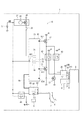
(第10実施形態)
本発明の第10実施形態による制御装置10を図17に示す。第10実施形態は、制御装置10を構成する部材数が多い点等で第1実施形態と異なる。
第10実施形態では、制御装置10は、ECU90、高電位側ドライバ57をさらに備えている。
ECU90は、アイドルストップECU70と構成がほぼ同様の電子制御ユニットである。ECU90は、概念的な機能部として、始動制御部92、始動完了判定部93、自動停止許可部94を備えている。
(10th Embodiment)
A
In the tenth embodiment, the
The
始動制御部92、始動完了判定部93、自動停止許可部94は、それぞれ、構成上および機能上、アイドルストップECU70の始動制御部72、始動完了判定部73、自動停止許可部74と同様のため、説明を省略する。このように、本実施形態では、構成および機能が略同じECUを2つ(70、90)備えている。
始動制御部92は、アイドルストップECU70が異常でエンジン2の初回始動ができない場合、アイドルストップECU70に代わって、エンジン2を初回始動させる。自動停止許可部94は、アイドルストップECU70が異常でエンジン2の初回始動ができず、ECU90により初回始動した場合、アイドルストップECU70の自動停止制御部71によるエンジン2の停止を禁止する。このように、始動制御部92および自動停止許可部94は、アイドルストップECU70の異常時に機能する、バックアップ用の機能部である。
ECU90は、筐体64に収容されており、入力部602、出力部615、入力部623を有している。ここで、筐体64は、特許請求の範囲における「第1筐体」に対応している。
The
When the
The
高電位側ドライバ57は、高電位側ドライバ51と同様、例えばp−MOS等のスイッチング素子であり、ソースが高電位側端子+Bに接続し、ドレインがリレー41のコイルに接続し、ゲートがECU90の出力部615に接続している。
アイドルストップECU70の入力部621、および、ECU90の入力部623は、それぞれ、高電位側ドライバ51とリレー41との間に接続している。
ECU90の入力部602は、インヒビタスイッチ23に接続している。
また、信号線65は、アイドルストップECU70とECU90とエンジンECU80とを相互に接続している。
Similarly to the high
The
An
Further, the
本実施形態では、通常、第1実施形態と同様、アイドルストップECU70によりスタータ30およびエンジン2を制御する。この場合、ECU90は、機能せず、出力部615から高電位側ドライバ57に対し「始動用信号」は出力されない。
In the present embodiment, the
一方、例えば、プッシュスタータ21から「初回始動意思信号(ON)」がECU90の入力部602に入力されたにもかかわらず、入力部623に「モニタ信号(ON)」が入力されなかった場合、ECU90は、「アイドルストップECU70に異常が生じている」と判断し、アイドルストップECU70に代わってエンジン2を初回始動させる。
On the other hand, for example, when the “initial start intention signal (ON)” is input from the
このように、本実施形態では、例えば故障等によりアイドルストップECU70に異常が生じても、ECU90によりエンジン2の初回の始動を行うことができる。よって、制御装置10によるエンジン2の初回始動の信頼性を向上することができる。
As described above, in this embodiment, even if an abnormality occurs in the
(他の実施形態)
上述の複数の実施形態は、構成上の阻害要因がない限り、どのように組み合わせてもよい。例えば、第2実施形態と第6実施形態とを組み合わせ、初回始動意思検出部としてキースタータ25を採用し、始動デバイスとして、2つのソレノイド(36、37)を備えるスタータ30を採用するといった具合である。
(Other embodiments)
The above-described embodiments may be combined in any way as long as there are no structural obstruction factors. For example, the second embodiment and the sixth embodiment are combined, the
また、上述の第1〜6実施形態では、第1筐体としての筐体61に自動停止制御部71、始動制御部72、始動完了判定部73、自動停止許可部74を収容し、第2筐体としての筐体62に車両状態判定部81、持続運転判定部82を収容する例を示した。これに対し、本発明の他の実施形態では、機能部としての自動停止制御部71、始動制御部72、始動完了判定部73、自動停止許可部74、車両状態判定部81、持続運転判定部82は、筐体61、62のそれぞれに、どのように振り分けて収容してもよい。各機能部間の信号の送受信は、筐体61と筐体62とを接続する信号線65を用いて行うことができる。また、信号線65には、CAN規格に準じた信号に限らず、他の規格等に準じた信号が流れることとしてもよい。
In the first to sixth embodiments described above, the automatic
また、上述の第10実施形態では、通常、アイドルストップECU70によりスタータ30およびエンジン2を制御しエンジン2の初回始動および自動停止後の再始動等を行い、アイドルストップECU70に異常が生じた場合、ECU90によりエンジン2の初回始動のみを行う例を示した。これに対し、本発明の他の実施形態では、ECU90は、アイドルストップECU70の自動停止制御部71と同様の構成および機能の「自動停止制御部」をさらに有していてもよい。この構成の場合、通常、アイドルストップECU70によりスタータ30およびエンジン2を制御しエンジン2の初回始動および自動停止後の再始動等を行い、アイドルストップECU70に異常が生じた場合、アイドルストップECU70に代わって、ECU90によりエンジン2の初回始動および自動停止後の再始動等を行うことが可能である。また、この構成の場合、通常、ECU90によりスタータ30およびエンジン2を制御しエンジン2の初回始動および自動停止後の再始動等を行い、ECU90に異常が生じた場合、アイドルストップECU70によるスタータ30およびエンジン2の制御に切り替えることとしてもよい。つまり、この構成では、アイドルストップECU70、ECU90は、どちらをメインで使用してもよい。また、アイドルストップECU70、ECU90は、互いに機能を分担しつつスタータ30およびエンジン2を同時に制御してもよい。
Further, in the tenth embodiment described above, when the
また、上述の実施形態では、車両状態判定部81が、車速センサ9からの信号に基づき、車両1が加速状態、惰性走行状態、減速状態、停車状態のいずれの状態であるかを判定する例を示した。これに対し、本発明の他の実施形態では、車両状態判定部81は、例えば車両1の加速度を検出可能な加速度センサ等からの信号に基づき、車両1の状態を判定してもよい。
In the above-described embodiment, the vehicle
また、上述の実施形態では、制御装置10が、車両状態判定部81および持続運転判定部82を含むエンジンECU80を備える例を示した。これに対し、本発明の他の実施形態では、制御装置10は、車両状態判定部81および持続運転判定部82を備えないこととしてもよい。この場合、制御装置10は、例えば車速センサ9からの信号に基づき車両1の状態を判定でき、例えばクランク角センサ8からの信号に基づき「エンジン2が持続運転状態であるか否か」および「エンジン2の始動が完了したか否か」を判定可能である。
Moreover, in the above-mentioned embodiment, the
また、上述の実施形態では、車両1が惰性走行状態のとき、エンジンECU80が、エンジン2とトランスミッションとの接続を解除する例を示した。これに対し、本発明の他の実施形態では、車両1が惰性走行状態のとき、エンジンECU80は、エンジン2とトランスミッションとの接続を解除しないこととしてもよい。
Further, in the above-described embodiment, the example in which the
また、本発明の他の実施形態では、エンジン2の停止の条件である自動停止条件、および、エンジン2の始動の条件である自動始動条件は、アクセルペダル6またはブレーキペダル7の踏み込み量、ならびに、クランク角センサ8、車速センサ9、または、その他のセンサからの信号等に基づき、適宜、設定することができる。
また、上述の実施形態では、始動デバイスとしてスタータ(30)を用いる例を示した。これに対し、本発明の他の実施形態では、始動デバイスは、エンジンの始動に特化したスタータに限らず、例えば、力行によるエンジンの始動および回生による発電が可能なISG(インテグレーテッドスタータジェネレータ)、あるいは、ハイブリッド車等に搭載され力行によるエンジンの始動および車輪の駆動ならびに回生による発電が可能なMG(モータジェネレータ)等であってもよい。
In another embodiment of the present invention, the automatic stop condition, which is a condition for stopping the
Moreover, in the above-mentioned embodiment, the example which uses a starter (30) as a starting device was shown. On the other hand, in another embodiment of the present invention, the starting device is not limited to a starter specialized for starting the engine, but for example, an ISG (Integrated Starter Generator) capable of starting the engine by power running and generating electricity by regeneration. Alternatively, it may be an MG (Motor Generator) or the like that is mounted on a hybrid vehicle or the like and can start an engine and drive wheels by power running and generate electricity by regeneration.
また、本発明の他の実施形態では、制御装置10が実行する機能の一部または全部を、1つあるいは複数のIC等によりハードウェア的に構成してもよい。制御装置10が提供する機能は、実体的なメモリ装置に記録されたソフトウェアおよびそれを実行するコンピュータ、ソフトウェアのみ、ハードウェアのみ、あるいは、それらの組み合わせによって提供することができる。例えば、制御装置10がハードウェアである電子回路によって提供される場合、それは多数の論理回路を含むデジタル回路またはアナログ回路によって提供することができる。
このように、本発明は、上述の実施形態に限定されるものではなく、その要旨を逸脱しない範囲で種々の形態に適用可能である。
In another embodiment of the present invention, part or all of the functions executed by the
Thus, the present invention is not limited to the above-described embodiments, and can be applied to various forms without departing from the gist thereof.
1 車両、2 エンジン(内燃機関)、3 駆動軸、21 プッシュスタータ(初回始動意思検出部)、25 キースタータ(初回始動意思検出部)、30 スタータ(始動デバイス)、10 制御装置、71 自動停止制御部、72、92 始動制御部、73、93 始動完了判定部、74、94 自動停止許可部 1 vehicle, 2 engine (internal combustion engine), 3 drive shaft, 21 push starter (initial start intention detection unit), 25 key starter (initial start intention detection unit), 30 starter (start device), 10 control device, 71 automatic stop Control unit, 72, 92 Start control unit, 73, 93 Start completion determination unit, 74, 94 Automatic stop permission unit
Claims (16)
前記内燃機関の停止の条件である自動停止条件が成立したとき、前記内燃機関を制御することにより前記内燃機関を自動で停止させることが可能な自動停止制御部(71)と、
前記初回始動意思検出部から前記初回始動意思信号を受信したとき、および、前記内燃機関の始動の条件である自動始動条件が成立したとき、前記始動デバイスへの通電を制御し、前記始動デバイスを駆動することにより前記内燃機関を始動させることが可能な始動制御部(72、92)と、
前記内燃機関の始動が完了したか否かを判定可能な始動完了判定部(73、93)と、
前記始動制御部が前記初回始動意思検出部から前記初回始動意思信号を受信し前記内燃機関を始動させるとき、前記始動完了判定部により「前記内燃機関の始動が完了した」と判定した場合、前記自動停止制御部による前記内燃機関の停止を許可する自動停止許可部(74、94)と、
を備える制御装置。 An internal combustion engine (2), an initial start intention detector (21, 25) capable of detecting an initial start intention of the internal combustion engine by a driver and outputting an initial start intention signal which is a signal corresponding to the initial start intention; And a control for controlling the internal combustion engine provided in the vehicle (1) including a start device (30) that is driven by energization to rotate the drive shaft (3) of the internal combustion engine and start the internal combustion engine. A device (10) comprising:
An automatic stop control unit (71) capable of automatically stopping the internal combustion engine by controlling the internal combustion engine when an automatic stop condition, which is a condition for stopping the internal combustion engine, is established;
When receiving the initial start intention signal from the initial start intention detection unit and when an automatic start condition that is a condition for starting the internal combustion engine is established, the energization to the start device is controlled, and the start device is A start control unit (72, 92) capable of starting the internal combustion engine by driving;
A start completion determination unit (73, 93) capable of determining whether or not the start of the internal combustion engine is completed;
When the start control unit receives the initial start intention signal from the initial start intention detection unit and starts the internal combustion engine, when the start completion determination unit determines that the start of the internal combustion engine is completed, An automatic stop permission unit (74, 94) for permitting the automatic stop control unit to stop the internal combustion engine;
A control device comprising:
前記自動停止制御部は、前記車両状態判定部により前記車両が惰性走行状態、減速状態または停車状態のいずれかの状態であると判定し、かつ、前記自動停止条件が成立したとき、前記内燃機関を停止させることが可能である請求項1に記載の制御装置。 A vehicle state determination unit (81) capable of determining the state of the vehicle;
The automatic stop control unit determines that the vehicle state determination unit determines that the vehicle is in an inertia running state, a deceleration state, or a stopped state, and the internal combustion engine is satisfied when the automatic stop condition is satisfied. The control device according to claim 1, wherein the control device can be stopped.
前記始動完了判定部は、前記持続運転判定部により「前記内燃機関は持続運転状態である」と判定したとき、「前記内燃機関の始動が完了した」と判定する請求項1または2に記載の制御装置。 A continuous operation determination unit (82) for determining whether or not the internal combustion engine is in a continuous operation state in which the internal combustion engine is in a continuous operation;
3. The start completion determination unit according to claim 1, wherein when the continuous operation determination unit determines that the internal combustion engine is in a continuous operation state, the start completion determination unit determines that the start of the internal combustion engine has been completed. Control device.
少なくとも前記持続運転判定部を収容する第2筐体(62)と、
前記始動完了判定部と前記持続運転判定部とを接続し、信号が流れる信号線(65)と、をさらに備え、
前記持続運転判定部は、判定した結果に対応する信号を、前記信号線を経由して前記始動完了判定部に伝送する請求項3または4に記載の制御装置。 A first housing (61, 64) that houses at least the start completion determination unit;
A second housing (62) for accommodating at least the continuous operation determination unit;
The start completion determination unit and the continuous operation determination unit are connected, and further includes a signal line (65) through which a signal flows,
The control device according to claim 3 or 4, wherein the continuous operation determination unit transmits a signal corresponding to the determined result to the start completion determination unit via the signal line.
前記初回始動意思検出部は、運転者が押下可能なボタン(22)を有するプッシュスタータ(21)である請求項1〜8のいずれか一項に記載の制御装置。 Further comprising the initial start intention detection unit,
The control device according to any one of claims 1 to 8, wherein the initial start intention detection unit is a push starter (21) having a button (22) that can be pressed by a driver.
前記初回始動意思検出部は、キー(27)を差し込み可能な穴部(26)を有するキースタータ(25)である請求項1〜8のいずれか一項に記載の制御装置。 Further comprising the initial start intention detection unit,
The control device according to any one of claims 1 to 8, wherein the initial start intention detection unit is a key starter (25) having a hole (26) into which a key (27) can be inserted.
前記リレーに対し高電位側に設けられ、信号の入力により、高電位側から前記リレーへの通電を許容または遮断可能な高電位側ドライバ(51)と、
前記リレーに対し低電位側に設けられ、信号の入力により、前記リレーから低電位側への通電を許容または遮断可能な低電位側ドライバ(52、53、54)と、
をさらに備える請求項1〜10のいずれか一項に記載の制御装置。 Relays (41, 42, 43) that allow energization to the starting device by being energized, and cut off energization to the starting device by being de-energized;
A high potential side driver (51) provided on the high potential side with respect to the relay and capable of allowing or interrupting energization of the relay from the high potential side by input of a signal;
A low potential side driver (52, 53, 54) provided on the low potential side with respect to the relay and capable of allowing or interrupting energization from the relay to the low potential side by input of a signal;
The control device according to any one of claims 1 to 10, further comprising:
前記始動デバイスは、モータ(31)、前記モータの回転により回転するピニオンギア(32)、通電されることにより前記モータへの通電を許容するモータ通電許容部(36)、および、通電されることにより前記駆動軸に設けられたリングギア(4)に前記ピニオンギアが噛み合うよう前記リングギアに向けて前記ピニオンギアを押し出すことが可能な押し出し部(37)を有する請求項1〜11のいずれか一項に記載の制御装置。 Further comprising the starting device;
The starting device includes a motor (31), a pinion gear (32) that is rotated by the rotation of the motor, a motor energization allowing part (36) that allows energization of the motor when energized, and an energization 12. A push-out portion (37) capable of pushing out the pinion gear toward the ring gear so that the pinion gear meshes with a ring gear (4) provided on the drive shaft. The control device according to one item.
前記リレーに対し高電位側に設けられ、信号の入力により、高電位側から前記リレーへの通電を許容または遮断可能な高電位側ドライバ(51)と、
前記リレーに対し低電位側に設けられ、信号の入力により、前記リレーから低電位側への通電を許容または遮断可能な低電位側ドライバ(53、54)と、をさらに備え、
前記リレーは、前記モータ通電許容部および前記押し出し部のそれぞれに対し1つずつ、計2つ設けられ、
前記高電位側ドライバは、2つの前記リレーに対し高電位側に共通で1つ設けられ、
前記低電位側ドライバは、2つの前記リレーに対し低電位側にそれぞれ1つずつ、計2つ設けられている請求項12に記載の制御装置。 Relays (42, 43) that allow energization to the starting device by being energized, and cut off energization to the starting device by being de-energized;
A high potential side driver (51) provided on the high potential side with respect to the relay and capable of allowing or interrupting energization of the relay from the high potential side by input of a signal;
A low-potential-side driver (53, 54) provided on the low-potential side with respect to the relay and capable of allowing or interrupting energization from the relay to the low-potential side by input of a signal;
Two relays are provided, one for each of the motor energization allowing portion and the pushing portion,
The high potential side driver is provided in common on the high potential side for the two relays,
The control device according to claim 12, wherein a total of two low potential side drivers are provided on the low potential side with respect to the two relays.
前記始動制御部が正常なとき、前記バイパス始動部による前記内燃機関の始動を禁止し、
前記始動制御部が異常なとき、前記バイパス始動部による前記内燃機関の始動を許容する請求項1〜14のいずれか一項に記載の制御装置。 Provided between the initial start intention detection unit and the start device so as to bypass the start control unit, and when the initial start intention signal is received from the initial start intention detection unit, energization to the start device is permitted. And further comprising a bypass starter (55, 56) capable of starting the internal combustion engine by driving the starter device,
When the start control unit is normal, prohibiting the start of the internal combustion engine by the bypass start unit,
The control device according to any one of claims 1 to 14, wherein when the start control unit is abnormal, the internal combustion engine is allowed to start by the bypass start unit.
Priority Applications (4)
| Application Number | Priority Date | Filing Date | Title |
|---|---|---|---|
| JP2016012331A JP2017133388A (en) | 2016-01-26 | 2016-01-26 | Control device |
| DE102017101252.4A DE102017101252A1 (en) | 2016-01-26 | 2017-01-24 | Engine control device |
| CN201710061075.4A CN106996338A (en) | 2016-01-26 | 2017-01-25 | Device for controlling engine |
| US15/416,070 US9995230B2 (en) | 2016-01-26 | 2017-01-26 | Engine control device |
Applications Claiming Priority (1)
| Application Number | Priority Date | Filing Date | Title |
|---|---|---|---|
| JP2016012331A JP2017133388A (en) | 2016-01-26 | 2016-01-26 | Control device |
Publications (1)
| Publication Number | Publication Date |
|---|---|
| JP2017133388A true JP2017133388A (en) | 2017-08-03 |
Family
ID=59295478
Family Applications (1)
| Application Number | Title | Priority Date | Filing Date |
|---|---|---|---|
| JP2016012331A Pending JP2017133388A (en) | 2016-01-26 | 2016-01-26 | Control device |
Country Status (4)
| Country | Link |
|---|---|
| US (1) | US9995230B2 (en) |
| JP (1) | JP2017133388A (en) |
| CN (1) | CN106996338A (en) |
| DE (1) | DE102017101252A1 (en) |
Families Citing this family (2)
| Publication number | Priority date | Publication date | Assignee | Title |
|---|---|---|---|---|
| WO2021199074A1 (en) * | 2020-03-31 | 2021-10-07 | Tvs Motor Company Limited | An engine management system for a vehicle |
| DE102020130075A1 (en) | 2020-11-13 | 2022-05-19 | Volkswagen Aktiengesellschaft | Tank system for motor vehicles |
Citations (7)
| Publication number | Priority date | Publication date | Assignee | Title |
|---|---|---|---|---|
| JPH02227557A (en) * | 1989-02-28 | 1990-09-10 | Suzuki Motor Co Ltd | Automatic starting device for automobile |
| JP2005036795A (en) * | 2003-06-27 | 2005-02-10 | Toyota Motor Corp | On-vehicle engine starting control device |
| JP2005264929A (en) * | 2004-02-18 | 2005-09-29 | Yamaha Motor Co Ltd | Straddling type vehicle, engine control equipment, and idle stop release method |
| JP2005330813A (en) * | 2004-05-18 | 2005-12-02 | Denso Corp | Engine automatic stopping restarting device |
| JP2006321268A (en) * | 2005-05-17 | 2006-11-30 | Fujitsu Ten Ltd | Economic running control method and economic running controlling device |
| JP2010144653A (en) * | 2008-12-19 | 2010-07-01 | Denso Corp | Electronic control device |
| JP2012225332A (en) * | 2011-04-22 | 2012-11-15 | Denso Corp | Failure detecting device of starter control device |
Family Cites Families (6)
| Publication number | Priority date | Publication date | Assignee | Title |
|---|---|---|---|---|
| JPS569826B2 (en) | 1972-12-21 | 1981-03-04 | ||
| FR2709790B1 (en) * | 1993-09-09 | 1995-11-17 | Renault | Method for supplying fuel to an internal combustion engine and engine for implementing it. |
| TWI341362B (en) * | 2004-02-18 | 2011-05-01 | Yamaha Motor Co Ltd | Saddle type vehicle, and engine controlling apparatus and idle stop canceling method for the saddle type vehicle |
| JP5496157B2 (en) * | 2011-08-23 | 2014-05-21 | 日立オートモティブシステムズ株式会社 | Engine control device |
| JP5609826B2 (en) | 2011-09-06 | 2014-10-22 | 三菱自動車工業株式会社 | Vehicle control device |
| JP2014009628A (en) | 2012-06-29 | 2014-01-20 | Suzuki Motor Corp | Idling stop control device of vehicle |
-
2016
- 2016-01-26 JP JP2016012331A patent/JP2017133388A/en active Pending
-
2017
- 2017-01-24 DE DE102017101252.4A patent/DE102017101252A1/en not_active Withdrawn
- 2017-01-25 CN CN201710061075.4A patent/CN106996338A/en active Pending
- 2017-01-26 US US15/416,070 patent/US9995230B2/en active Active
Patent Citations (7)
| Publication number | Priority date | Publication date | Assignee | Title |
|---|---|---|---|---|
| JPH02227557A (en) * | 1989-02-28 | 1990-09-10 | Suzuki Motor Co Ltd | Automatic starting device for automobile |
| JP2005036795A (en) * | 2003-06-27 | 2005-02-10 | Toyota Motor Corp | On-vehicle engine starting control device |
| JP2005264929A (en) * | 2004-02-18 | 2005-09-29 | Yamaha Motor Co Ltd | Straddling type vehicle, engine control equipment, and idle stop release method |
| JP2005330813A (en) * | 2004-05-18 | 2005-12-02 | Denso Corp | Engine automatic stopping restarting device |
| JP2006321268A (en) * | 2005-05-17 | 2006-11-30 | Fujitsu Ten Ltd | Economic running control method and economic running controlling device |
| JP2010144653A (en) * | 2008-12-19 | 2010-07-01 | Denso Corp | Electronic control device |
| JP2012225332A (en) * | 2011-04-22 | 2012-11-15 | Denso Corp | Failure detecting device of starter control device |
Also Published As
| Publication number | Publication date |
|---|---|
| DE102017101252A1 (en) | 2017-07-27 |
| CN106996338A (en) | 2017-08-01 |
| US20170211494A1 (en) | 2017-07-27 |
| US9995230B2 (en) | 2018-06-12 |
Similar Documents
| Publication | Publication Date | Title |
|---|---|---|
| US7665438B2 (en) | Starter device for an internal combustion engine having separate engaging process and starting process | |
| JP3760840B2 (en) | Automatic engine stop / restart system for vehicles | |
| US6494809B1 (en) | Engine control apparatus and engine control method | |
| JP2006322332A (en) | Failure detection method for starter drive circuit and economical running control device | |
| JP5413518B2 (en) | Vehicle travel control device | |
| JP2010229882A (en) | Vehicle control device and idling stop system | |
| US20120216768A1 (en) | Starter control apparatus | |
| JP2015093553A (en) | Vehicular control apparatus | |
| JP2006327217A (en) | Program for vehicle control and electronic control device for vehicle | |
| JP2017133388A (en) | Control device | |
| JP2006257900A (en) | Starter of internal combustion engine | |
| CN103221669A (en) | Control device and control method for engine, engine start device, and vehicle | |
| JP2001289084A (en) | Motor vehicle with transmission controlled by electronic transmission unit | |
| JP7438622B2 (en) | Vehicle control device | |
| JP5406666B2 (en) | Voltage control apparatus and idling stop function invalidating method | |
| JP5737406B2 (en) | VEHICLE CONTROL DEVICE, VEHICLE, AND METHOD FOR CONTROLLING VEHICLE | |
| JP2016120800A (en) | Vehicle control device | |
| JP4569580B2 (en) | Vehicle and control method thereof | |
| KR20200026615A (en) | Method for ISG Restart Control Based On Over-current Protection and Manual Transmission ISG System Thereof | |
| JP4186633B2 (en) | Automobile and control method thereof | |
| JP2014144712A (en) | Vehicle and control method of vehicle | |
| JP6007816B2 (en) | Vehicle control device | |
| JP2019203422A (en) | Engine start controller | |
| JP5951342B2 (en) | Vehicle control device | |
| JP2017160805A (en) | Engine starting device |
Legal Events
| Date | Code | Title | Description |
|---|---|---|---|
| A621 | Written request for application examination |
Free format text: JAPANESE INTERMEDIATE CODE: A621 Effective date: 20180413 |
|
| A977 | Report on retrieval |
Free format text: JAPANESE INTERMEDIATE CODE: A971007 Effective date: 20190123 |
|
| A131 | Notification of reasons for refusal |
Free format text: JAPANESE INTERMEDIATE CODE: A131 Effective date: 20190129 |
|
| A521 | Request for written amendment filed |
Free format text: JAPANESE INTERMEDIATE CODE: A523 Effective date: 20190328 |
|
| A02 | Decision of refusal |
Free format text: JAPANESE INTERMEDIATE CODE: A02 Effective date: 20190423 |