JP2017128308A - Control system for vehicle - Google Patents
Control system for vehicle Download PDFInfo
- Publication number
- JP2017128308A JP2017128308A JP2016010889A JP2016010889A JP2017128308A JP 2017128308 A JP2017128308 A JP 2017128308A JP 2016010889 A JP2016010889 A JP 2016010889A JP 2016010889 A JP2016010889 A JP 2016010889A JP 2017128308 A JP2017128308 A JP 2017128308A
- Authority
- JP
- Japan
- Prior art keywords
- program
- electronic control
- control unit
- vehicle
- ecu
- Prior art date
- Legal status (The legal status is an assumption and is not a legal conclusion. Google has not performed a legal analysis and makes no representation as to the accuracy of the status listed.)
- Granted
Links
- 238000012545 processing Methods 0.000 claims abstract description 86
- 230000008859 change Effects 0.000 claims description 31
- 230000004044 response Effects 0.000 claims description 8
- 230000006870 function Effects 0.000 description 65
- 238000000034 method Methods 0.000 description 35
- 230000005540 biological transmission Effects 0.000 description 28
- 230000008569 process Effects 0.000 description 27
- 238000004891 communication Methods 0.000 description 22
- 238000007726 management method Methods 0.000 description 21
- 230000006399 behavior Effects 0.000 description 19
- 230000007246 mechanism Effects 0.000 description 13
- 230000005856 abnormality Effects 0.000 description 12
- 230000033001 locomotion Effects 0.000 description 12
- 230000001172 regenerating effect Effects 0.000 description 12
- 238000001514 detection method Methods 0.000 description 11
- 238000012508 change request Methods 0.000 description 7
- 230000001133 acceleration Effects 0.000 description 6
- 239000000446 fuel Substances 0.000 description 5
- 238000002347 injection Methods 0.000 description 5
- 239000007924 injection Substances 0.000 description 5
- 238000006243 chemical reaction Methods 0.000 description 3
- 239000002131 composite material Substances 0.000 description 3
- 238000010586 diagram Methods 0.000 description 2
- 230000002093 peripheral effect Effects 0.000 description 2
- 238000013468 resource allocation Methods 0.000 description 2
- 230000001360 synchronised effect Effects 0.000 description 2
- 238000013519 translation Methods 0.000 description 2
- 238000012795 verification Methods 0.000 description 2
- 230000002159 abnormal effect Effects 0.000 description 1
- 238000007664 blowing Methods 0.000 description 1
- 150000001875 compounds Chemical class 0.000 description 1
- 238000003745 diagnosis Methods 0.000 description 1
- 239000012530 fluid Substances 0.000 description 1
- 238000004519 manufacturing process Methods 0.000 description 1
- 239000000203 mixture Substances 0.000 description 1
- 238000012986 modification Methods 0.000 description 1
- 230000004048 modification Effects 0.000 description 1
- 238000012544 monitoring process Methods 0.000 description 1
- 230000000737 periodic effect Effects 0.000 description 1
- 238000012805 post-processing Methods 0.000 description 1
- 239000000725 suspension Substances 0.000 description 1
Images


Classifications
-
- G—PHYSICS
- G06—COMPUTING; CALCULATING OR COUNTING
- G06F—ELECTRIC DIGITAL DATA PROCESSING
- G06F9/00—Arrangements for program control, e.g. control units
- G06F9/06—Arrangements for program control, e.g. control units using stored programs, i.e. using an internal store of processing equipment to receive or retain programs
- G06F9/44—Arrangements for executing specific programs
- G06F9/455—Emulation; Interpretation; Software simulation, e.g. virtualisation or emulation of application or operating system execution engines
Abstract
Description
本発明は、車両に搭載された車載機器を制御するために、第1の電子制御装置と第2の電子制御装置とが連携した処理を行う車両用制御システムに関する。 The present invention relates to a vehicle control system that performs processing in which a first electronic control device and a second electronic control device cooperate in order to control an in-vehicle device mounted on a vehicle.
例えば、特許文献1には、階層的に配置された複数の制御ユニットから構成される車載電子機器制御システムについて記載されている。この車載電子機器制御システムは、例えば、リヤデフォッガーとデフロスターとの動作制御に適用される。車載電子機器制御システムは、リヤデフォッガーの基本制御系の制御ユニットECU11と、その上位に位置付けられる自動化拡張機能系の制御ユニットECU21とを有する。また、車載電子機器制御システムは、デフロスターの基本制御系の制御ユニットECU12と、その上位に位置する自動化拡張機能系の制御ユニットECU22とを有する。さらに、車載電子機器制御システムは、リヤデフォッガーの自動化拡張機能系の制御ユニットECU21及びデフロスターの自動化拡張機能系の制御ユニットECU22の上位に位置付けられる、連携制御ユニットECU31を有している。 For example, Patent Document 1 describes an in-vehicle electronic device control system including a plurality of control units arranged hierarchically. This on-vehicle electronic device control system is applied to, for example, operation control of a rear defogger and a defroster. The in-vehicle electronic device control system includes a control unit ECU 11 of a basic control system of a rear defogger and a control unit ECU 21 of an automated extended function system positioned above it. The in-vehicle electronic device control system includes a control unit ECU 12 of a basic control system of a defroster and a control unit ECU 22 of an automation extended function system positioned above it. Furthermore, vehicle electronic device control system is positioned on top of the control unit ECU 22 of the automated extension system of the control unit ECU 21 and defroster automated extension system of the rear defogger, and a cooperative control unit ECU 31.
このような構成において、リヤデフスイッチがオン操作されると、基本制御系の制御ユニットECU11がリヤデフォッガーに通電制御する。このとき、自動化拡張機能系の制御ユニットECU21は、リヤデフォッガーの動作継続時間をタイマー計測し、タイムアップしたときに、リヤデフォッガーをオートオフする自動制御を行う。 In such a configuration, when the rear differential switch is turned on, the control unit ECU 11 of the basic control system controls the energization of the rear defogger. At this time, the control unit ECU 21 of the automation extension function system measures the operation continuation time of the rear defogger by a timer, and performs automatic control for automatically turning off the rear defogger when the time is up.
また、フロントデフスイッチがオン操作されると、基本制御系の制御ユニットECU21が、エアコンの吹出しモードとして、デフロスターを選択する。そして、自動化拡張機能系の制御ユニットECU22は、外気温センサが検出する外気温と、ユーザによるフロントデフスイッチの操作履歴を記録し、窓曇り条件を累積学習する。自動化拡張機能系の制御ユニットECU22は、次回、検出された外気温が窓曇り条件を充足した場合、フロントデフスイッチが操作されずとも、デフロスターをオートオンする自動制御を行う。 When the front differential switch is turned on, the control unit ECU 21 of the basic control system selects the defroster as the air-conditioner blowing mode. Then, the control unit ECU 22 of the automated extended function system records the outside air temperature detected by the outside air temperature sensor and the operation history of the front differential switch by the user, and cumulatively learns the window fogging condition. When the detected outside air temperature satisfies the window fogging condition next time, the control unit ECU 22 of the automated extended function system performs automatic control to automatically turn on the defroster without operating the front differential switch.
さらに、連携制御ユニットECU31は、リヤデフォッガーとデフロスターとの動作履歴を記録し、連携動作学習を行う。例えば、デフロスターの動作時に、リヤデフォッガーが一定頻度以上で同時に動作する学習結果となっている場合、デフロスターが動作開始したときに、連携制御ユニットECU31は、リヤデフォッガーの自動化拡張機能系の制御ユニットECU21に対し、リヤデフォッガーをオートオンする指令を出力する。 Further, the cooperation control unit ECU 31 records the operation history of the rear defogger and the defroster, and performs the cooperation operation learning. For example, when the operation of the defroster is a learning result in which the rear defogger operates simultaneously with a certain frequency or more, when the defroster starts the operation, the cooperative control unit ECU 31 controls the control unit of the automated extended function system of the rear defogger. A command to automatically turn on the rear defogger is output to the ECU 21 .
上述した特許文献1に記載された車載電子機器制御システムのように、制御システムが複数の電子制御装置(制御ユニット)により構成され、各電子制御装置によって連携した制御が行われることがある。このような連携した制御を行うために、例えば、予め電子制御装置間でやり取りされる信号や処理手順などを厳密に定め、それに応じた連携処理用アプリケーションプログラムを作成したとする。この場合、制御システムが、いわゆる専用品となってしまい、例えば車両のグレードや車種に応じた低機能から高機能までのバリエーションに対応したり、電子制御装置を構成するハードウエアの変更に対応したりすることが困難になってしまう。 Like the vehicle-mounted electronic device control system described in Patent Document 1 described above, the control system may be configured by a plurality of electronic control devices (control units), and coordinated control may be performed by each electronic control device. In order to perform such coordinated control, for example, it is assumed that signals and processing procedures exchanged between electronic control devices are determined in advance, and an application program for cooperative processing corresponding thereto is created. In this case, the control system becomes a so-called dedicated product, for example, corresponding to variations from low function to high function according to the grade and model of the vehicle, or to changing hardware constituting the electronic control device. It becomes difficult to do.
そこで、第1の電子制御装置と第2の電子制御装置とが連携した処理を行う場合に、連携処理用アプリケーションの他に、それら連携処理用アプリケーションプログラムを協調して実行させるためのベーシックソフトウエアとしての役割を果たすOSプログラムを、第1及び第2の電子制御装置にそれぞれ設けることが考えられる。 Therefore, in the case where the first electronic control device and the second electronic control device perform cooperative processing, in addition to the cooperative processing application, basic software for cooperatively executing the cooperative processing application program It is conceivable to provide the first and second electronic control devices with OS programs that serve as
例えば、OSプログラムが、各電子制御装置間の通信データの検証、データの変換、同期メカニズム、リソースの配分等をサポートすることにより、第1及び第2の電子制御装置における連携処理用アプリケーションプログラムは、それぞれの制御機能に特化して作成することができ、制御機能の追加、変更などにも容易に対応可能となる。また、各OSプログラムが、各電子制御装置のハードウエアを抽象化することができるので、この点においても、連携処理用アプリケーションの汎用性を高めることができる。 For example, the OS program supports verification of communication data between each electronic control device, data conversion, synchronization mechanism, resource allocation, etc., so that the application program for cooperative processing in the first and second electronic control devices is Therefore, it can be created specifically for each control function, and the addition and change of the control function can be easily handled. Further, since each OS program can abstract the hardware of each electronic control device, the versatility of the cooperation processing application can be enhanced in this respect as well.
ただし、第1及び第2の電子制御装置による連携処理をサポートするOSプログラムを、第1及び第2の電子制御装置にそれぞれ設ける場合、それらのOSプログラムは、定められた役割分担の下に協調して動作する必要がある。しかしながら、その役割分担が常に一定であるとすると、例えば、用いられる電子制御装置の能力の相違などに起因して、必ずしもそれぞれの電子制御装置の能力に見合った役割とはならず、連携処理のサポートを効率的に行いえない虞がある。 However, when OS programs that support cooperative processing by the first and second electronic control devices are provided in the first and second electronic control devices, respectively, the OS programs are coordinated under a defined role assignment. Need to work. However, assuming that the division of roles is always constant, for example, due to differences in the capabilities of the electronic control devices used, the roles do not necessarily correspond to the capabilities of the respective electronic control devices. There is a possibility that support cannot be performed efficiently.
本発明は、上述した点に鑑みてなされたものであり、第1の電子制御装置及び第2の電子制御装置にそれぞれ設けられたOSプログラムにより、第1の電子制御装置と第2の電子制御装置との連携処理を効率的にサポートすることが可能な車両用制御システムを提供することを目的とする。 The present invention has been made in view of the above-described points, and the first electronic control device and the second electronic control are executed by OS programs respectively provided in the first electronic control device and the second electronic control device. It is an object of the present invention to provide a vehicle control system that can efficiently support cooperation processing with an apparatus.
上記目的を達成するために、本発明による車両用制御システムは、
車両に搭載された車載機器(31〜33)を制御するために、第1の電子制御装置(40)と第2の電子制御装置(60、70、80)とが連携した処理を行うものであって、
第1の電子制御装置と第2の電子制御装置とは、それぞれ、連携処理を行うための連携処理用アプリケーションプログラム(41a、61a、71a、81a)を有するとともに、それら連携処理用アプリケーションプログラムを協調して実行させるためのベーシックソフトウエアとしての役割を果たす、所定の役割分担の下に協調して動作する第1OSプログラム(41b)と第2OSプログラム(61b、71b、81b)とをそれぞれ有しており、
第2の電子制御装置が保有する第2OSプログラムは、分担する役割が異なる複数の中から選定されたものであり、
第1の電子制御装置が保有する第1OSプログラムは、分担する役割を変更可能に構成され、それにより、分担する役割が異なる複数の中のいずれの第2OSプログラムとも協調した動作を行うことが可能であって、
第1の電子制御装置は、
第2の電子制御装置から、第2OSプログラムが分担する役割についての情報を取得する取得部(S100)と、
取得部により取得した、第2OSプログラムが分担する役割を示す情報に基づき、当該第2OSプログラムと協調して動作することができるように、第1OSプログラムの分担する役割を決定する決定部(S120)と、を備える。
In order to achieve the above object, a vehicle control system according to the present invention comprises:
In order to control the in-vehicle devices (31 to 33) mounted on the vehicle, the first electronic control device (40) and the second electronic control device (60, 70, 80) perform a coordinated process. There,
Each of the first electronic control device and the second electronic control device has a cooperative processing application program (41a, 61a, 71a, 81a) for performing the cooperative processing, and cooperates with the cooperative processing application program. Each having a first OS program (41b) and a second OS program (61b, 71b, 81b) that operate in a coordinated manner under a predetermined division of roles. And
The second OS program possessed by the second electronic control device is selected from a plurality of roles that are shared,
The first OS program held by the first electronic control unit is configured so that the roles to be shared can be changed, and thereby, it is possible to perform an operation in cooperation with any of the second OS programs in a plurality of roles to be shared. Because
The first electronic control unit
An acquisition unit (S100) for acquiring information about a role shared by the second OS program from the second electronic control unit;
A determination unit that determines a role shared by the first OS program based on information acquired by the acquisition unit and indicating a role shared by the second OS program so that the second OS program can operate in cooperation with the second OS program (S120). And comprising.
このように、本発明による車両用制御システムによれば、第1の電子制御装置が保有する第1OSプログラムは、第2OSプログラムが分担する役割についての情報を取得し、その第2OSプログラムが分担する役割を示す情報に基づき、当該第2OSプログラムと協調して動作することができるように、第1OSプログラムの分担する役割を決定する。従って、例えば、第2の電子制御装置の能力に起因して第2OSプログラムの役割分担が変動しても、その役割分担の変動に応じて、第1OSプログラムが、第2OSプログラムと協調して動作することができるように、自動的に、分担する役割を変化させることができる。その結果、第1の電子制御装置及び第2の電子制御装置に設けられたOSプログラムにより、第1の電子制御装置と第2の電子制御装置との連携処理を効率的にサポートすることが可能になる。 Thus, according to the vehicle control system of the present invention, the first OS program held by the first electronic control unit acquires information about the role shared by the second OS program, and the second OS program shares the second OS program. Based on the information indicating the role, the role to be shared by the first OS program is determined so that it can operate in cooperation with the second OS program. Therefore, for example, even if the role assignment of the second OS program varies due to the capability of the second electronic control unit, the first OS program operates in cooperation with the second OS program according to the change in the role assignment. The role to share can be changed automatically so that it can be done. As a result, the OS program provided in the first electronic control device and the second electronic control device can efficiently support the cooperation processing between the first electronic control device and the second electronic control device. become.
上記括弧内の参照番号は、本発明の理解を容易にすべく、後述する実施形態における具体的な構成との対応関係の一例を示すものにすぎず、なんら本発明の範囲を制限することを意図したものではない。 The reference numerals in the parentheses merely show an example of a correspondence relationship with a specific configuration in an embodiment described later in order to facilitate understanding of the present invention, and are intended to limit the scope of the present invention. Not intended.
また、上述した特徴以外の、特許請求の範囲の各請求項に記載した技術的特徴に関しては、後述する実施形態の説明及び添付図面から明らかになる。 Further, the technical features described in the claims of the claims other than the features described above will become apparent from the description of embodiments and the accompanying drawings described later.
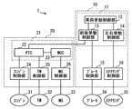
以下、本発明の実施形態に係る車両用制御システムについて、図面を参照しつつ説明する。本実施形態に係る車両用制御システム1は、例えば、図1に示すように、走行駆動源として、エンジン31と電動モータ(モータジェネレータ)33とを有するハイブリッド車両に適用され、このハイブリッド車両に搭載された各種の車載機器31〜35を制御するために用いられる。しかしながら、本実施形態に係る車両用制御システム1は、ハイブリッド車両における車載機器31〜35を制御に適用されることに限られる訳ではなく、エンジンのみを有する通常の車両や、電動モータのみを有する電動車両の車載機器の制御に適用されても良い。
Hereinafter, a vehicle control system according to an embodiment of the present invention will be described with reference to the drawings. For example, as shown in FIG. 1, the vehicle control system 1 according to the present embodiment is applied to a hybrid vehicle having an
図1は、上述したハイブリッド車両における複数の車載機器31〜35を制御するために、車両用制御システム1が有する各種機能の一例を機能ブロック図として表したものである。ただし、図1には、車両用制御システム1が有する機能の全てが示されている訳ではない。これは、説明の便宜のため、図1には、本実施形態に係る車両用制御システム1の構成の一例しか示していないためである。
FIG. 1 is a functional block diagram illustrating an example of various functions of the vehicle control system 1 in order to control the plurality of in-
図1において、車両用制御システム1は、車載機器としてのエンジン31,トランスミッション(TM)32、モータジェネレータ(MG)33、ブレーキ装置34、及びステアリング装置35などを制御するための機能を有する。しかしながら、上述したように、車両用制御システム1は、さらに、例えば、サスペンション、高圧バッテリ、エアコン装置などのその他の車載機器を制御するための機能を有していても良い。
In FIG. 1, the vehicle control system 1 has a function for controlling an
図1に示すように、車両用制御システム1は、各種の車載機器31〜35を制御するための機能が予め複数の論理ブロック(機能ブロック)12〜16、22〜26に区分けされ、それら複数の論理ブロック12〜16、22〜26間の連結関係を規定することによって構成されている。すなわち、車両用制御システム1における各種の車載機器31〜35を制御するための論理構造が、論理ブロック12〜16、22〜26と、それら論理ブロック12〜16、22〜26間の連結関係によって規定されている。そして、車両用制御システム1は、複数の論理ブロック12〜16、22〜26が、規定された連結関係に従って連携して動作することにより、各種の車載機器31〜35を制御する。
As shown in FIG. 1, in the vehicle control system 1, functions for controlling various in-
なお、図1には示していないが、各論理ブロック12〜16、22〜26は、少なくとも1つ、通常は多数の制御ブロックを有している。各論理ブロック12〜16、22〜26は、それら多数の制御ブロックにおける演算処理を適宜組み合わせることにより、それぞれの機能(役割)を発揮する。
Although not shown in FIG. 1, each of the
例えば、論理ブロックとしてのエンジン制御部24は、エンジン31の運転状態を検出すべく、各種のセンサからのセンサ信号を入力して、論理ブロック内で取り扱うことができる信号に変換する制御ブロックを有する。また、センサ信号から把握されるエンジン31の運転状態から現状の発生トルクを算出する制御ブロックを有する。さらに、上位の論理ブロック(パワートレインコーディネータ(PTC)22)から指示された指令トルクと現状の発生トルクとに差異がある場合に、その差異をなくすための目標とするエンジン運転状態を算出する制御ブロックを有する。また、目標エンジン運転状態を達成するためのスロットルバルブ開度、燃料噴射量と燃料噴射時期、及び点火時期を算出する制御ブロックを有する。ただし、これらは単なる例示であって、エンジン制御部24は、その機能を発揮するために必要な、その他の演算処理を行う制御ブロックを有する場合もあり得る。また、例示された制御ブロックを含め、エンジン制御部24内の制御ブロックは、適宜、統合されたり、逆に、細分化されたりすることが可能なものである。
For example, the
車両用制御システム1は、実際には、各論理ブロック12〜16、22〜26を、プログラムやデータベースなどの制御アプリケーションとして、複数の電子制御装置に振り分けて実装することにより具現化される。この場合、複数の電子制御装置は、論理ブロック12〜16、22〜26の連結関係を維持できるように、個別の通信線を介して接続されたり、各電子制御装置が共通のネットワークに接続され、連結関係に従う所望の電子制御装置同士が通信可能に構成されたりする。なお、必ずしも各論理ブロック12〜16、22〜26をそれぞれ別個の電子制御装置に実装する必要はなく、幾つかの論理ブロックを共通の電子制御装置に実装しても良い。 The vehicle control system 1 is actually realized by distributing and mounting each of the logic blocks 12 to 16 and 22 to 26 as a control application such as a program or a database on a plurality of electronic control devices. In this case, the plurality of electronic control devices are connected via individual communication lines, or each electronic control device is connected to a common network so that the connection relationship of the logic blocks 12 to 16 and 22 to 26 can be maintained. The desired electronic control devices according to the connection relationship may be configured to communicate with each other. Note that it is not always necessary to mount each of the logic blocks 12 to 16 and 22 to 26 on separate electronic control devices, and some logic blocks may be mounted on a common electronic control device.
本実施形態に係る車両用制御システム1は、複数の車載機器31〜35の機能に応じて予め複数のドメインに区分けされている。別の表現をすれば、各論理ブロック12〜16、22〜26が果たすべき機能のまとまりに応じて、予め複数のドメイン10、20に区分けされている。
The vehicle control system 1 according to the present embodiment is divided into a plurality of domains in advance according to the functions of the plurality of in-
複数の車載機器31〜35は、いずれかのドメイン10、20に割り振られる。そして、割り振られたドメイン10、20に属するドメイン制御部11、21が、各車載機器31〜35の制御目標値を算出して、車載機器31〜35の制御を司る車載機器制御部15、16、24〜26へ出力したりする。なお、図1に示すように、各ドメイン制御部11、21は、少なくとも1つの論理ブロックから構成される。
The plurality of in-
具体的には、図1に示す例では、制御システム1は、運動ドメイン10とエネルギードメイン20とに区分けされている。そして、運動ドメイン10には、前後方向及び横方向における車両の挙動を制御する機能を担う運動ドメイン制御部11が設けられている。また、エネルギードメイン20には、車両を加速させたり、減速させたり、あるいは速度を一定に保つように、車両の動力を制御する機能を担うエネルギードメイン制御部21が設けられている。
Specifically, in the example illustrated in FIG. 1, the control system 1 is divided into a
また、本実施形態に係る車両用制御システム1では、図1に示すように、各ドメイン制御部11、21の下に、対応するドメイン制御部11、21からの指令(制御目標値)に従い、各車載機器31〜35の動作状態を制御する車載機器制御部15、16、24〜26が設けられている。これら車載機器制御部15、16、24〜26は、各車載機器31〜35の動作状態をドメイン制御部11、21からの制御目標値に近づけるための制御信号を生成し、各車載機器31〜35に出力する。
Moreover, in the vehicle control system 1 according to the present embodiment, as shown in FIG. 1, under each
具体的には、図1に示す例では、運動ドメイン制御部11の下に、ブレーキ装置34を制御するブレーキ制御部15及びステアリング装置35を制御するステアリング制御部16が設けられている。また、エネルギードメイン制御部21の下に、エンジン31を制御するエンジン制御部24、トランスミッション32を制御するトランスミッション(TM)制御部25、及びモータジェネレータ33を制御するMG制御部26が設けられている。
Specifically, in the example illustrated in FIG. 1, a
なお、モータジェネレータ33は、車両の減速時などに回生エネルギーを発生する。MG制御部26の上位の論理ブロックであるモータジェネレータコーディネータ(MGC)23は、その回生エネルギーの生成も管理する。このエネルギーは、インバータによってDC変換され、図示しない高圧バッテリに蓄電される。
The
ここで、図1に論理ブロック12〜16、22〜26として例示した、車両用制御システム1が有する各種の機能について詳しく説明する。 Here, various functions of the vehicle control system 1 exemplified as the logic blocks 12 to 16 and 22 to 26 in FIG. 1 will be described in detail.
車両用制御システム1には、各論理ブロック12〜16、22〜26が与えられた機能を発揮するために必要な各種の情報が入力される。例えば、図示しない各種のセンサによって、ハイブリッド車両の運転のため、運転者によって操作される各種の操作部(アクセルペダル、ブレーキペダル、シフトレバー、ステアリングホイールなど)の操作が検出され、その操作検出信号が車両用制御システム1に入力される。また、車両の走行状態(例えば、速度、加速度、ヨーレートなど)や、各種の車載機器31〜35の動作状態(例えば、エンジン温度、エンジン回転数、トランスミッション変速比、インバータ温度、モータ回転数、ブレーキ油圧、操舵角など)を検出するセンサからの動作検出信号も、車両用制御システム1に入力される。
The vehicle control system 1 receives various types of information necessary for the
上述した各種の信号は、車両用制御システム1の各ドメイン制御部11、21や車載機器制御部15、16、24〜26に与えられる。
The various signals described above are given to the
例えば、運動ドメイン制御部11には、運転者による各種の操作部の操作を示す操作検出信号、及び車両の走行状態を検出するセンサからの動作検出信号が入力される。そして、運動ドメイン制御部11は、原則として、車両が運転者による操作部の操作に応じた挙動を示すように、ブレーキ装置34及びステアリング装置35の制御目標値を算出する。具体的には、車両挙動制御部12が、車両の挙動を安定させつつ、運転者の操作に対応するように車両の挙動を制御すべく、前後挙動制御部13に対して前後方向の目標加速度(目標減速度)を与えるとともに、左右挙動制御部14に対して左右方向の目標加速度を与える。前後挙動制御部13は、与えられた前後方向の目標加速度(目標減速度)を実現すべく、エネルギードメイン制御部21のパワートレインコーディネータ(PTC)22に対して目標駆動トルク(加速トルク又は制動トルク)を出力するとともに、ブレーキ制御部15に対して、ブレーキ装置34の制御目標値である目標制動トルクを出力する。また、左右挙動制御部14は、与えられた左右方向の目標加速度を実現すべく、ステアリング制御部16に対して、ステアリング装置35の制御目標値である目標アシストトルクを出力する。
For example, the motion
なお、例えば、運動ドメイン制御部11に、車両の走行車線を区画する白線の認識情報や、先行車両や障害物の情報など、車両の外部環境に関する情報を与えるようにしてもよい。これにより、運動ドメイン制御部11において、例えば、白線によって区画される走行車線を逸脱しないように、ステアリング装置35のアシスト力を調整する(レーンキープアシスト)ように制御目標値を算出することが可能となる。また、運動ドメイン制御部11にて、例えば、先行車両や障害物との衝突を避けるように、ブレーキ装置34やステアリング装置35の制御目標値を算出することが可能となる。
For example, the motion
また、エネルギードメイン制御部21には、例えば、図示しない高圧バッテリの電圧や電流を検出するセンサ信号や、車両の走行状態を示すセンサ信号などが入力される。エネルギードメイン制御部21のMGC23は、それらのセンサ信号に基づいて、高圧バッテリの蓄電量を算出する。さらに、MGC23は、主として、高圧バッテリの蓄電量に基づいて、モータジェネレータ33が発生可能な最大MGトルクを算出して、PTC22に与える。PTC22は、運動ドメイン制御部11から与えられた目標駆動トルク(加速トルク)を最も効率良く実現するために、モータジェネレータ33が発生可能な最大MGトルクや、センサ信号に基づく車両の走行状態を考慮しつつ、エンジン31が発生すべき目標エンジントルク、トランスミッション32が実現すべき目標変速比、及びモータジェネレータ33が発生すべき目標MGトルクを算出する。算出された目標エンジントルク、目標変速比、及び目標MGトルクは、それぞれ、制御目標値として、エンジン制御部24、TM制御部25、及びMGC23に与えられる。また、TM制御部25に対しては、クラッチの動作に関する制御目標値(クラッチの接続開始時期や、クラッチの接続完了までの時間など)も与えられても良い。
In addition, for example, a sensor signal for detecting a voltage or current of a high voltage battery (not shown), a sensor signal indicating a running state of the vehicle, or the like is input to the energy
さらに、エネルギードメイン制御部21のMGC23は、車両の減速時等において、主として、高圧バッテリの蓄電量に基づいてモータジェネレータ33が発生可能な回生電力量を算出する。この回生電力量に対応する回生制動トルクに関する情報は、MGC23から、PTC22を介して運動ドメイン制御部11の前後挙動制御部13に与えられる。
Further, the
前後挙動制御部13は、車両挙動制御部12から目標減速度が与えられた場合、その目標減速度を実現するための目標制動トルクを算出する。そして、モータジェネレータ33が回生制動トルクを発生可能である場合には、極力、その回生制動トルクを活用するように、ブレーキ装置34による目標制動トルクと、回生ブレーキによる目標回生制動トルクとを定める。この目標回生制動トルクは、制御目標値として、PTC22を介して、エネルギードメイン制御部21のMGC23に与えられる。
When the target deceleration is given from the vehicle
ブレーキ制御部15は、前後挙動制御部13から与えられたブレーキ装置34の制御目標値である目標制動トルクに従い、ブレーキ装置34を制御する。より具体的には、ブレーキ制御部15は、ブレーキ装置34が目標制動トルクを発生するようにブレーキフルード圧を制御するための制御信号を出力する。また、ステアリング制御部16も、ステアリング装置35が左右挙動制御部14から与えられた目標アシストトルクを発生するように制御信号を出力して、ステアリング装置35におけるアシストトルクを制御する。
The
エンジン制御部24は、PTC22から与えられた目標エンジントルクを実現するための制御信号をエンジン31に出力する。より詳細には、エンジン制御部24は、エンジン31の運転状態を検出する各種のセンサ(回転数、温度、空気流量等)からのセンサ信号を入力する。そして、センサ信号から把握されるエンジンの運転状態から現状の発生トルクを算出する。エンジン制御部24は、現状の発生トルクを目標エンジントルクに近づけるためのエンジン運転状態を算出し、その算出したエンジン運転状態を達成するための燃料噴射量と燃料噴射時期、及び点火時期を求め、これらに応じた噴射制御信号及び点火制御信号をエンジン31に出力する。
The
TM制御部25も、PTC22から目標変速比が与えられ、この与えられた目標変速比を実現するための制御信号をトランスミッション32に出力する。また、TM制御部25は、トランスミッション32において変速比を変更する場合、クラッチの動作に関する制御目標値に従って、クラッチの動作を制御するための制御信号も出力する。
The
MG制御部26は、MGC23から目標MGトルクが与えられた場合には、その目標MGトルクを発生させるように、モータジェネレータ33のインバータへ制御信号を出力する。一方、MG制御部26は、MGC23から目標回生制動トルクが与えられた場合には、その目標回生制動トルクに相当する制動力をモータジェネレータ33が車軸に対して付与するように、モータジェネレータ33のインバータへ制御信号を出力する。
When the target MG torque is given from the
上述したように、車両用制御システム1を構成する各論理ブロック12〜16、22〜26は、複数の論理ブロック12〜16、22〜26により連携した制御処理を行うことで、各車載機器31〜35を制御する。例えば、PTC22は、運動ドメイン10における前後挙動制御部13と協調したドメイン間連携制御、及び、MGC23、エンジン制御部24、並びにTM制御部25と協調したドメイン内連携制御を実行する。
As described above, each of the
ここで、上述した車両用制御システム1において、各論理ブロック12〜16、22〜26が実装される電子制御装置間でやり取りされる信号や処理手順などを厳密に定め、それに応じた連携処理用アプリケーションプログラムを作成することも可能である。しかしながら、この場合、車両用制御システム1が、いわゆる専用品となってしまい、例えば車両のグレードや車種に応じた低機能から高機能までのバリエーションに対応したり、電子制御装置を構成するハードウエアの変更に対応したりすることが困難になってしまう。
Here, in the vehicle control system 1 described above, signals and processing procedures that are exchanged between the electronic control devices on which the
そこで、各論理ブロック12〜16、22〜26が実装される複数の電子制御装置が連携した処理を行う場合に、連携処理用アプリケーションの他に、それら連携処理用アプリケーションプログラムを協調して実行させるためのベーシックソフトウエアとしての役割を果たすOSプログラムを、各電子制御装置に設けることが考えられる。
Therefore, when a plurality of electronic control devices in which the
例えば、OSプログラムが、各電子制御装置間における通信データの検証、データの変換、同期メカニズム、リソースの配分等をサポートすることにより、各電子制御装置における連携処理用アプリケーションプログラムは、それぞれの制御機能に特化して作成することができ、制御機能の追加、変更などにも容易に対応可能となる。また、各OSプログラムが、各電子制御装置のハードウエアを抽象化することができるので、この点においても、連携処理用アプリケーションの汎用性を高めることができるようになる。 For example, the OS program supports verification of communication data between each electronic control device, data conversion, synchronization mechanism, resource allocation, etc., so that the application program for cooperative processing in each electronic control device has its control function It is possible to specialize and create control functions, and can easily cope with addition and change of control functions. In addition, since each OS program can abstract the hardware of each electronic control device, the versatility of the cooperation processing application can be enhanced in this respect as well.
ただし、各電子制御装置による連携処理をサポートするOSプログラムを、各電子制御装置にそれぞれ設ける場合、それらのOSプログラムは、定められた役割分担の下に協調して動作する必要がある。しかしながら、その役割分担が常に一定であるとすると、例えば、用いられる電子制御装置の能力の相違に起因して、必ずしもそれぞれの電子制御装置の能力に見合った役割とはならず、連携処理のサポートを効率的に行いえない虞がある。 However, when an OS program that supports cooperative processing by each electronic control device is provided in each electronic control device, these OS programs need to operate in a coordinated manner under a defined role assignment. However, if the division of roles is always constant, for example, due to differences in the capabilities of the electronic control devices used, the roles do not necessarily match the capabilities of each electronic control device, and support for cooperative processing May not be performed efficiently.
そこで、本実施形態に係る車両用制御システム1では、各電子制御装置による連携処理をサポートするOSプログラムの役割を変更可能に構成した。具体的には、連携した処理を行う少なくとも2つの電子制御装置において、一方をマスターECU、他方をスレーブECUとした場合に、まず、マスターECUが保有する第1OSプログラムは、スレーブECUが保有する第2OSプログラムが分担する役割についての情報を取得する。そして、第1OSプログラムは、第2OSプログラムが分担する役割を示す情報に基づき、当該第2OSプログラムと協調して動作することができるように、第1OSプログラムの分担する役割を決定する。従って、例えば、スレーブECUの能力に起因して第2OSプログラムの役割分担が変動しても、その役割分担の変動に応じて、第1OSプログラムが、第2OSプログラムと協調して動作することができるように、自動的に、分担する役割を変化させることができる。その結果、マスターECU及びスレーブECUに設けられた各OSプログラムにより、マスターECUとスレーブECUとの連携処理を効率的にサポートすることが可能になる。 Therefore, the vehicle control system 1 according to the present embodiment is configured to be able to change the role of the OS program that supports cooperation processing by each electronic control device. Specifically, in at least two electronic control devices that perform linked processing, when one is a master ECU and the other is a slave ECU, first, the first OS program that the master ECU has is the first OS program that the slave ECU has. Information on the roles shared by the 2OS program is acquired. Then, the first OS program determines the role shared by the first OS program based on the information indicating the role shared by the second OS program so that the first OS program can operate in cooperation with the second OS program. Therefore, for example, even if the role assignment of the second OS program varies due to the ability of the slave ECU, the first OS program can operate in cooperation with the second OS program according to the change in the role assignment. As described above, the shared role can be automatically changed. As a result, each OS program provided in the master ECU and the slave ECU can efficiently support the cooperation processing between the master ECU and the slave ECU.
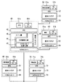
まず、図2を参照して、各電子制御装置にOSプログラムを設ける場合の構成の一例を説明するとともに、OSプログラムが連携処理をサポートするために実施する処理内容などの具体例を説明する。 First, with reference to FIG. 2, an example of a configuration in the case where an OS program is provided in each electronic control device will be described, and a specific example of processing contents that the OS program implements to support cooperation processing will be described.
図2は、エネルギードメイン制御部21のPTC22が、電子制御装置40にPTCアプリケーション41aとして実装され、その電子制御装置40にアプリケーションの1つとしてOSプログラム41bを設けた場合の構成を示している。なお、図2には、PTC22と直接的に通信を行って連携処理を実行する論理ブロック(前後挙動制御部13、MGC23、エンジン制御部24、TM制御部25)として機能するアプリケーション51a、61a、71a、81aをそれぞれ実装した電子制御装置50、60、70、80の構成も示している。これら電子制御装置50、60、70、80においても、アプリケーションの1つとして、それぞれOSプログラム51b、61b、71b、81bが設けられている。
FIG. 2 shows a configuration in which the
なお、PTCアプリケーション41a、前後挙動制御アプリケーション51a、MGCアプリケーション61b、TM制御アプリケーション71a、EMS制御アプリケーション81aが、それぞれ連携処理用アプリケーションに相当する。
Note that the
また、図2には、各電子制御装置40、50、60、70、80が、それぞれ1つのOSプログラム41b、51b、61b、71b、81bを有するように示されているが、各電子制御装置40、50、60、70、80は、通信相手毎に、異なるOSプログラムを有する。通信相手が異なることにより、連携処理をサポートするために提供すべきサービス内容も異なるためである。例えば、PTCアプリケーション41aが実装された電子制御装置40は、上位のドメイン制御部である前後挙動制御部13としての電子制御装置50との連携処理をサポートするためのOSプログラム、同じエネルギードメイン制御部21に属するMGC23としての電子制御装置60との連携処理をサポートするためのOSプログラム、下位の機器制御部であるTM制御部25としての電子制御装置70との連携処理をサポートするためのOSプログラム、及びエンジン制御部24としての電子制御装置80との連携処理をサポートするためのOSプログラムをそれぞれ有している。
2 shows that each
ただし、PTC22としての電子制御装置40は、機器制御部に分類されるTM制御部25、エンジン制御部24がそれぞれ実装された電子制御装置70及び電子制御装置80との連携処理をサポートするためのOSプログラムを共通化しても良い。この場合、電子制御装置70及び電子制御装置80のOSプログラムの役割や動作条件が相違していてもそれらの相違を包含するデータやサービスを提供するように、電子制御装置40のOSプログラムを設定することで、OSプログラムを共通化することができる。
However, the
そして、原則として、上位の電子制御装置がマスターECUとなり、下位の電子制御装置がスレーブECUとなる。なお、同位の電子制御装置の場合、いずれか一方がマスターECUとなり、他方がスレーブECUとなる。 In principle, the upper electronic control device becomes the master ECU, and the lower electronic control device becomes the slave ECU. In the case of the same electronic control device, either one is a master ECU and the other is a slave ECU.
電子制御装置40〜80は、それぞれ、メモリを有しており、図2に示す構造のソフトウエアを、それぞれのメモリに記憶している。各電子制御装置40〜80は、図2に示すように、いわゆるAUTOSAR(AUTomotive Open System ARchitecture)に準拠するソフトウエア構造を有している。そこで、PTCアプリケーション41aを実装した電子制御装置40を代表例として、各電子制御装置40〜80のソフトウエア構造について説明する。
Each of the
電子制御装置40では、図2に示すように、ハードウエアであるマイクロコントローラ47に対して、ソフトウエアが搭載され、そのソフトウエアは、大きくは、基本ソフトウエア43〜46、ランタイム環境(RTE)42、及び、アプリケーション層に含まれるアプリケーションソフトウエアに分けられる。その中で、PTCアプリケーション41aは、アプリケーション層に実装され、このPTCアプリケーション41aが実行されることにより、電子制御装置40は、PTC22としての機能を発揮する。PTCアプリケーション41aは、実際には、PTC22としての各種の機能ごとに、複数のサブアプリケーションに分割されている。また、OSプログラム41bも、一つのアプリケーションソフトウエアとして、アプリケーション層に実装されている。
In the
基本ソフトウエア43〜46は、マイクロコントローラ抽象化層43、ECU抽象化層44、サービス層45に階層化され、階層が高くなるほど、抽象化度合が強くなり、各種のハードウエアから独立するようになっている。また、基本ソフトウエア43〜46は、複合ドライバ46を含んでいる。
The
マイクロコントローラ抽象化層43は、基本ソフトウエア43〜46の最下層に位置し、マイクロコントローラドライバ、メモリドライバ、通信ドライバ、I/Oドライバなどを有する。このマイクロコントローラ抽象化層43は、マイクロコントローラ47のハードウエア構成に依存する部分である。しかし、このマイクロコントローラ抽象化層43によって、マイクロコントローラ47とその周辺機器とが抽象化されるため、これより上位の階層は、マイクロコントローラ47及び周辺機器から独立することになる。なお、マイクロコントローラ抽象化層43は、通信ドライバとして、複数の種類の通信ドライバ(例えば、CAN(登録商標)ドライバ、LINドライバ、FlexRay(登録商標)ドライバなど)を有している。そして、電子制御装置40は、例えば、通信相手の電子制御装置がドメイン内か、ドメイン外かなどにより、異なる通信ドライバ、すなわち異なる通信ネットワークを使用して通信を行う。
The
ECU抽象化層44は、マイクロコントローラ抽象化層43の上位に位置している。このECU抽象化層44は、電子制御装置40の基本コンポーネントを抽象化することにより、上位のソフトウエア層を、電子制御装置40のハードウエアから独立させるものである。このECU抽象化層44は、搭載機器抽象化、メモリハードウエア抽象化、通信ハードウエア抽象化、I/Oハードウエア抽象化などを含む。
The
サービス層45は、その一部が、ECU抽象化層44の上位に位置し、アプリケーションのための基本的なサービスを提供するためのものである。具体的には、サービス層45は、OS、車両ネットワークの通信と管理、メモリサービス、診断サービス、ECU状態管理などのサービスを提供する。このサービス層45は、大部分がハードウエアから独立している。
A part of the
複合ドライバ46は、複雑なセンサやアクチュエータを操作するための特殊な機能やタイミング要求を満たすような、他のレイヤにはない複雑な機能が必要な場合に使用されるものである。この複合ドライバ47は、例えば、燃料を噴射するインジェクタを駆動制御する場合などに使用される。
The
そして、RTE42は、上述した各層からなる基本ソフトウエア43〜46の上位に位置し、アプリケーション層に含まれる各種のアプリケーション41a、41bが、電子制御装置40に依存しないようにするためのものである。そのため、RTE42は、アプリケーション41a、41b間の通信や、アプリケーション41a、41bと基本ソフトウエア43〜46との通信を提供する。
The
このように、AUTOSARに準拠したソフトウエア構造を採用することで、アプリケーション41a、41bは、マイクロコントローラ47や電子制御装置40のハードウエアに依存せずに済むので、アプリケーション41a、41bの再利用性を高めることができる。
As described above, by adopting the software structure conforming to AUTOSAR, the
次に、OSプログラム41bについて、詳しく説明する。図2に示すように、OSプログラム41bは、アプリケーションソフトの1つとして具現化される。このOSプログラム41bは、PTCアプリケーション41bの各サブアプリケーションが、他の電子制御装置50〜80と連携した処理を行う際に、その連携処理をサポートするための各種のサービスを提供する。なお、図2に示す例では、現状のAUTOSARに準拠した基本ソフトウエアを前提とし、ECU間連携を実現するOSプログラムは、アプリケーションソフトとして、RTEを介し基本ソフトウエアと結合されている。しかし、OSプログラムは、アプリケーションソフトとして具現化する以外に、基本ソフトウエア内に組み入れることも可能である。
Next, the
図3に、OSプログラム41bが提供するサービスの一覧の例を示す。なお、図3においては、OSプログラム41bにより提供される各種のサービスを、DVFB(Domain Virtual Function Bus)、ドメインシステムOS(Domain System OS)、ドメインシステム抽象化(Domain System Abstraction)の3つの階層に分類して示している。OSプログラム41bは、図3に示すサービスの一部を提供するものであっても良いし、逆に、図3に示すサービスは一例であって、図3に示すサービス以外のサービスをも含むものであっても良い。
FIG. 3 shows an example of a list of services provided by the
DVFBに分類されるドメイン外内抽象化(Domain External-Internal Abstraction)サービスは、例えば、マスターECUからスレーブECUに、連携処理を行うためのデータ(制御目標データやセンサ検出データなど)が送信される場合に、マスターECUとドメインECUにおいて実行されるOSプログラムの各サービスの処理順を設定したり、そのサービスが実行される時間に関する整合を図ったりするものである。また、DVFBに分類される意味解釈ゲートウェイ(Semantic Gateway)サービスは、ドメイン外内にてデータが異なる場合に、対応するデータに翻訳するものである。 In the domain external-internal abstraction service classified as DVFB, for example, data (control target data, sensor detection data, and the like) is transmitted from the master ECU to the slave ECU. In this case, the processing order of each service of the OS program executed in the master ECU and the domain ECU is set, or the time for executing the service is matched. The semantic interpretation gateway (Semantic Gateway) service classified as DVFB translates data into corresponding data when the data is different inside and outside the domain.
ドメインシステムOSに分類されるリソース調停(Resource Arbitration)サービスは、例えば、マスターECUとスレーブECUとが同じ電子制御装置に実装され、メモリやコアなどのリソースを共用する場合に、そのリソースの配分や調整を行うものである。システムモード(System Mode)サービスは、マスターECUにおける制御モードと、スレーブECUにおける制御モードとが整合した制御モードとなるように、モード管理を行うものである。イベント管理(Event Manager)サービスは、例えばマスターECUとスレーブECUとで同期した処理を行わせるトリガとなるイベントの生成と配信を行うものである。スケジューラ(Scheduler)サービスは、マスターECUでの連携処理のスケジュールに基づいて、スレーブECUでの連携処理のスケジュールを定めるものである。同期メカニズム(Synchronized Mechanism)サービスは、イベントもしくは時間での制御の同期を図るためのものである。クロック(Clock)サービスは、マスターECUとスレーブECUとで共通の時刻を生成するとともに、必要に応じて、データにタイムスタンプを行うものである。セキュリティ(Security)サービスは、例えばIDデータに基づいて正規の通信相手を認証したり、パリティチェックなどにより通信データの正常性を確認したりするためのものである。診断(Diagnostic)サービスは、例えば、マスターECU及びスレーブECUの異常診断を行うとともに、必要に応じてフェールセーフ処理を実行するものである。安全機能メカニズム(Safety function Mechanism)サービスは、異常が重大である場合に、マスターECUとスレーブECUとの連携機能を停止するものである。 A resource arbitration service classified as a domain system OS is, for example, when a master ECU and a slave ECU are mounted on the same electronic control unit and share resources such as a memory and a core. Make adjustments. The system mode service performs mode management so that the control mode in the master ECU and the control mode in the slave ECU are matched. The event management (Event Manager) service generates and distributes an event serving as a trigger for performing processing synchronized between a master ECU and a slave ECU, for example. The scheduler service determines the schedule for the cooperation process in the slave ECU based on the schedule for the cooperation process in the master ECU. The synchronized mechanism service is intended to synchronize control by event or time. The clock service generates a common time between the master ECU and the slave ECU, and time stamps the data as necessary. The security service is for authenticating a regular communication partner based on ID data, for example, and confirming the normality of communication data by parity check or the like. The diagnostic service performs, for example, an abnormality diagnosis of the master ECU and the slave ECU and performs fail-safe processing as necessary. The safety function mechanism service stops the cooperation function between the master ECU and the slave ECU when the abnormality is serious.
ドメインシステム抽象化に分類される機能分散抽象化(Function Distribution Abstraction)サービスは、上述した各種のサービスを実現する上で、マスター側の第1OSプログラムと、スレーブ側の第2OSプログラムとの役割分担の管理を行うものである。つまり、本実施形態では、マスター側の第1OSプログラムとスレーブ側の第2OSプログラムとが協調して動作することにより、上述した各種のサービスを実現する。その際、本実施形態では、マスター側の第1OSプログラムとスレーブ側の第2OSプログラムとの役割を変更可能に構成している。そのため、マスター側の第1OSプログラムとスレーブ側の第2OSプログラムとが、それぞれ、どのような役割を担っているかを管理することが必要となる。支配抽象化(Ownership Abstraction)サービスは、マスター側の第1OSプログラムとスレーブ側の第2OSプログラムとによる、制御対象機器やセンサ機器などに対する制御責任の分担の管理を行うものである。なお、制御責任とは、制御対象機器に対して制御信号を出力したり、センサ機器からの検出信号の受信処理を行ったり、制御対象機器やセンサ機器が正常に動作しているか監視したりする役割を担っていることをいう。 The function distribution abstraction service, which is classified as domain system abstraction, distributes the roles of the first OS program on the master side and the second OS program on the slave side in realizing the various services described above. It is for management. That is, in the present embodiment, the above-described various services are realized by the cooperation of the first OS program on the master side and the second OS program on the slave side. In this case, in the present embodiment, the roles of the first OS program on the master side and the second OS program on the slave side can be changed. Therefore, it is necessary to manage what role the first OS program on the master side and the second OS program on the slave side each play. The Ownership Abstraction service manages the sharing of control responsibilities for controlled devices, sensor devices, etc., by the first OS program on the master side and the second OS program on the slave side. The responsibility for control is to output a control signal to the device to be controlled, receive a detection signal from the sensor device, or monitor whether the device to be controlled or the sensor device is operating normally. It means that you have a role.
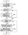
次に、図4及び図5のフローチャートを参照しつつ、マスター側の第1OSプログラムとスレーブ側の第2OSプログラムとが協調して動作可能とするための、設定方法について説明する。なお、第1OSプログラム及び第2OSプログラムの設定は、車両の製造ラインにおいて、車両用制御システムが構築された段階で実施される。また、機能向上のために、マスターECUやスレーブECUのアプリケーションソフトウエアが更新された場合にも実施される。 Next, a setting method for enabling the master side first OS program and the slave side second OS program to operate in cooperation with each other will be described with reference to the flowcharts of FIGS. 4 and 5. Note that the settings of the first OS program and the second OS program are performed at the stage where the vehicle control system is constructed in the vehicle production line. Moreover, it is implemented also when the application software of the master ECU and the slave ECU is updated to improve the function.
図4のフローチャートは、マスター側の第1OSプログラムによって実行される処理を示し、図5のフローチャートは、スレーブ側の第2OSプログラムによって実行される処理を示している。 The flowchart in FIG. 4 shows processing executed by the first OS program on the master side, and the flowchart in FIG. 5 shows processing executed by the second OS program on the slave side.
まず、図4のフローチャートのステップS100では、スレーブECUから、スレーブECUが保有する第2OSプログラムが分担する役割情報を取得する。この役割情報として、マスターECUは、上述した各種サービスに関して、スレーブECUの第2OSプログラムが担う役割を示す情報をそれぞれ取得しても良いし、第2OSプログラムに、予め、各種サービスに関する第2OSプログラムの役割の組み合わせを一義的に示す役割パターン情報を保有させておき、その役割パターン情報を取得しても良い。 First, in step S100 of the flowchart of FIG. 4, role information shared by the second OS program owned by the slave ECU is acquired from the slave ECU. As the role information, the master ECU may acquire information indicating the roles played by the second OS program of the slave ECU with respect to the various services described above, or the second OS program may store in advance the second OS program related to the various services. Role pattern information that uniquely indicates a combination of roles may be held, and the role pattern information may be acquired.
このように、スレーブECUが保有する第2OSプログラムは、上述した各種サービスに関して、第2OSプログラムが分担する役割が異なる複数のパターンの中から選定されたものである。このため、車両用制御システムの構成や、スレーブECUの能力などに応じて、第2OSプログラムの役割を適切に設定することが可能になる。 As described above, the second OS program held by the slave ECU is selected from a plurality of patterns having different roles shared by the second OS program with respect to the various services described above. Therefore, it is possible to appropriately set the role of the second OS program according to the configuration of the vehicle control system, the capability of the slave ECU, and the like.
続くステップS110では、取得した第2OSプログラムの各種サービスに関する役割が、マスターECUにおける第1OSプログラムの現状の役割と整合しているか否かを判定する。すなわち、マスターECUの第1OSプログラムは、平均的な第2OSプログラムの役割に対応するように、予め設定されている。ステップS110では、このような第1OSプログラムの基本設定で、既に第2OSプログラムの役割に整合しているか否かを判定する。このようにすれば、続くステップS120での第1OSプログラムの変更量を抑えることが可能になる。ただし、第1OSプログラムを事前に設定せずに、取得した第2OSプログラムに対応するように、すべてのサービス項目について、設定するようにしても良い。その場合、ステップS110の処理は省略可能である。 In a succeeding step S110, it is determined whether or not the roles related to various services of the acquired second OS program are consistent with the current roles of the first OS program in the master ECU. That is, the first OS program of the master ECU is set in advance so as to correspond to the role of the average second OS program. In step S110, it is determined whether or not the basic setting of the first OS program already matches the role of the second OS program. In this way, it is possible to suppress the amount of change of the first OS program in the subsequent step S120. However, all service items may be set so as to correspond to the acquired second OS program without setting the first OS program in advance. In that case, the process of step S110 can be omitted.
ステップS120では、各種サービスに関する第2OSプログラムの役割と整合するように、第1OSプログラムの役割を変更する。この際、第2OSプログラムの役割と整合していないサービス項目に関してのみ、第1OSプログラムの役割を変更すれば良いので、第1OSプログラムの変更処理を簡便に行うことができる。 In step S120, the role of the first OS program is changed so as to be consistent with the role of the second OS program related to various services. At this time, it is only necessary to change the role of the first OS program for service items that are not consistent with the role of the second OS program, so that the change process of the first OS program can be easily performed.
ここで、第1OSプログラムと第2OSプログラムとの役割が、各サービス項目に関して、どのように変化するかに関して、典型例を2例ほど示す。 Here, two typical examples will be shown as to how the roles of the first OS program and the second OS program change with respect to each service item.
図6は、マスターECUの第1OSプログラムの役割を軽くし、スレーブECUにおける第2OSプログラムの役割を重くした例を示している。 FIG. 6 shows an example in which the role of the first OS program in the master ECU is reduced and the role of the second OS program in the slave ECU is increased.
この場合、ドメイン外内抽象化サービスについて、マスターECUの第1OSプログラムは、スレーブECUの第2OSプログラムによる各サービスの処理順処理時間の設定には関与せず、スレーブECUの第2OSプログラムが、当該第2OSプログラムによるサービスの処理順や処理時間の設定を行う。また、意味解釈ゲートウェイサービスに関しては、マスターECUから送信されるデータの意味翻訳を、第2OSプログラムにおいて実行する。 In this case, for the intra-domain abstraction service, the first OS program of the master ECU is not involved in setting the processing order processing time of each service by the second OS program of the slave ECU, and the second OS program of the slave ECU The processing order and processing time of services by the second OS program are set. Further, regarding the semantic interpretation gateway service, semantic translation of data transmitted from the master ECU is executed in the second OS program.
リソース調停サービスに関しては、マスターECUにおける連携処理を優先して実行するために、第1OSプログラムが、その連携処理のためのリソースを確保する処理を行うが、残りリソースの利用調整は、第2OSプログラムにおいて行う。システムモードサービスに関しては、第1OSプログラムが連携処理のモードを生成し、第2OSプログラムは、その連携処理モードを受信し、対応するローカルモードへの変換を行い、スレーブECUの制御モードを、変換したローカルモードに設定する。 Regarding the resource arbitration service, in order to preferentially execute the cooperation process in the master ECU, the first OS program performs a process of securing resources for the cooperation process. To do. Regarding the system mode service, the first OS program generates the mode of the cooperative processing, and the second OS program receives the cooperative processing mode, performs conversion to the corresponding local mode, and converts the control mode of the slave ECU. Set to local mode.
イベント管理サービスに関しては、第1OSプログラムは、連携処理に用いる連携イベントを生成するとともに、スレーブECUに配信する。そして、第2OSプログラムは、配信された連携イベントを、スレーブECUにおいて取り扱うことが可能なローカルイベントに変換する。スケジューラサービスに関しては、第1OSプログラムが連携処理のスケジュールを生成し、第2OSプログラムが、その連携処理スケジュールをスレーブECUにおけるローカルスケジュールに変換する。同期メカニズムサービスに関しては、第1OSプログラムが、同期手段として、所定のイベントによる同期指示を選択した場合、その所定のイベントによる同期を実現するための実現機能を第2OSプログラムが選択する。例えば、第2OSプログラムは、イベント管理サービスがローカルイベントを生成している場合には、そのローカルイベントを同期手段として選択する。 Regarding the event management service, the first OS program generates a cooperation event used for the cooperation processing and distributes it to the slave ECU. Then, the second OS program converts the distributed cooperation event into a local event that can be handled by the slave ECU. Regarding the scheduler service, the first OS program generates a schedule for the cooperation process, and the second OS program converts the cooperation process schedule into a local schedule in the slave ECU. Regarding the synchronization mechanism service, when the first OS program selects a synchronization instruction based on a predetermined event as a synchronization means, the second OS program selects an implementation function for realizing synchronization based on the predetermined event. For example, when the event management service generates a local event, the second OS program selects the local event as a synchronization unit.
クロックサービスに関しては、第1OSプログラムが連携時刻を生成し、第2OSプログラムが、その連携時刻をスレーブECUにおけるローカル時刻に変換する。セキュリティサービスに関しては、第1OSプログラムが、マスターECUの通信相手の認証と、受信データの正常性の確認を行い、第2OSプログラムが、スレーブECUの通信相手の認証と、受信データの正常性の確認を行う。診断サービスに関しては、第1OSプログラムが、マスターECUにおける連携処理の異常検知と、異常時のフェールセーフ処理を行い、第2OSプログラムが、スレーブECUにおける連携処理の異常検知と、異常時のフェールセーフ処理を行う。安全機能メカニズムサービスに関しては、第1OSプログラムが、マスターECUにおける連携機能の停止を司り、第2OSプログラムが、スレーブECUにおけるローカル機能の停止を司る。 Regarding the clock service, the first OS program generates a cooperation time, and the second OS program converts the cooperation time into a local time in the slave ECU. Regarding the security service, the first OS program authenticates the communication partner of the master ECU and confirms the normality of the received data, and the second OS program authenticates the communication partner of the slave ECU and confirms the normality of the received data. I do. Regarding the diagnostic service, the first OS program performs the abnormality detection of the cooperation process in the master ECU and the fail-safe process at the time of abnormality, and the second OS program detects the abnormality of the cooperation process in the slave ECU and the fail-safe process at the time of abnormality. I do. Regarding the safety function mechanism service, the first OS program controls the stop of the cooperation function in the master ECU, and the second OS program controls the stop of the local function in the slave ECU.
機能分散抽象化サービスに関しては、マスターECUの第1OSプログラムは、マスター−スレーブ間の機能分担の管理に関与せず、スレーブECUの第2OSプログラムが、その機能分担の管理を行う。同様に、支配抽象化サービスについても、マスターECUの第1OSプログラムは、責任分担管理に関与せず、スレーブECUの第2OSプログラムが、その責任分担の管理を行う。 Regarding the function distribution abstraction service, the first OS program of the master ECU is not involved in the management of the function sharing between the master and the slave, and the second OS program of the slave ECU manages the function sharing. Similarly, for the control abstraction service, the first OS program of the master ECU does not participate in responsibility sharing management, and the second OS program of the slave ECU manages the responsibility sharing.
一方、図7は、マスターECUの第1OSプログラムの役割を重くし、スレーブECUにおける第2OSプログラムの役割を軽くした例を示している。 On the other hand, FIG. 7 shows an example in which the role of the first OS program of the master ECU is increased and the role of the second OS program in the slave ECU is reduced.
この場合、ドメイン外内抽象化サービスについて、マスターECUの第1OSプログラムは、スレーブECUの第2OSプログラムによる各サービスの処理順、処理時間の設定を行い、その設定内容を示すデータを送信する。スレーブECUの第2OSプログラムは、設定内容を示すデータを受信し、その受信されたデータに従って、各種のサービスを実行する。また、意味解釈ゲートウェイサービスに関しては、マスターECUの第1OSプログラムが、データの意味翻訳を行うとともに、翻訳されたデータをスレーブECUに送信する。スレーブECUの第2OSプログラムは、翻訳されたデータを受信し、処理に使用する。 In this case, for the intra-domain abstraction service, the first OS program of the master ECU sets the processing order and processing time of each service by the second OS program of the slave ECU, and transmits data indicating the setting contents. The second OS program of the slave ECU receives the data indicating the setting contents, and executes various services according to the received data. As for the semantic interpretation gateway service, the first OS program of the master ECU performs semantic translation of data and transmits the translated data to the slave ECU. The second OS program of the slave ECU receives the translated data and uses it for processing.
リソース調停サービスに関しては、第1OSプログラムが、マスターECUによる連携処理のためのリソースを確保する処理、さらに、残りリソースの配分処理も行う。第2OSプログラムは、配分されたリソースを使用するように、リソース管理を行う。システムモードサービスに関しては、第1OSプログラムが連携処理のモードを生成し、さらに、その連携イベントを対応するローカルモードに変換して、スレーブECUに送信する。第2OSプログラムは、変換されたローカルモードを受信し、スレーブECUの制御モードを、受信したローカルモードに設定する。 Regarding the resource arbitration service, the first OS program performs processing for securing resources for cooperation processing by the master ECU, and also performs processing for allocating remaining resources. The second OS program performs resource management so as to use the allocated resources. With respect to the system mode service, the first OS program generates a mode of cooperation processing, further converts the cooperation event into a corresponding local mode, and transmits it to the slave ECU. The second OS program receives the converted local mode, and sets the control mode of the slave ECU to the received local mode.
イベント管理サービスに関しては、第1OSプログラムは、連携処理に用いる連携イベントを生成するとともに、その連携イベントを、スレーブECUにおいて取り扱うことが可能なローカルイベントに変換する。第2OSプログラムは、ローカルイベントを受信し、そのローカルイベントに基づく処理が行われるようにする。スケジューラサービスに関しては、第1OSプログラムが連携処理のスケジュールを生成し、さらに、その連携処理スケジュールをスレーブECUにおけるローカルスケジュールに変換して、送信する。第2OSプログラムは、ローカルスケジュールを受信し、そのローカルスケジュールに基づくスケジュール管理を行う。同期メカニズムサービスに関しては、第1OSプログラムが、連携処理における同期手段に対応するローカル同期手段を選定して、送信する。第2OSプログラムは、受信したローカル同期手段を受信し、以降の処理に使用する。 With respect to the event management service, the first OS program generates a cooperation event used for the cooperation processing, and converts the cooperation event into a local event that can be handled by the slave ECU. The second OS program receives a local event and performs processing based on the local event. As for the scheduler service, the first OS program generates a schedule for the cooperation process, and further converts the cooperation process schedule into a local schedule in the slave ECU and transmits it. The second OS program receives the local schedule and performs schedule management based on the local schedule. As for the synchronization mechanism service, the first OS program selects and transmits a local synchronization unit corresponding to the synchronization unit in the cooperation process. The second OS program receives the received local synchronization means and uses it for the subsequent processing.
クロックサービスに関しては、第1OSプログラムが連携時刻を生成し、さらに、その連携時刻をスレーブECUにおけるローカル時刻に変換して送信する。第2OSプログラムは、ローカル時刻を受信し、処理に使用する。セキュリティサービスに関しては、第1OSプログラムが、マスターECU及びスレーブECUについて一括して管理する。例えば、第1OSプログラムが、マスターECU及びスレーブECUの通信相手の認証を行ったり、マスター−スレーブ間で送受信されるデータの正常性の確認を行ったりする。この場合、第2OSプログラムは、セキュリティサービスは扱わない。診断サービスに関しては、第1OSプログラムが、マスターECUにおける連携処理の異常検知と、異常時のフェールセーフ処理を行うとともに、異常検知結果をスレーブECUに通知する。第2OSプログラムは、その異常検知通知を受信する。安全機能メカニズムサービスに関しては、第1OSプログラムが、マスターECUにおける連携機能の停止を司るとともに、必要時にローカル機能の停止を指示する。第2OSプログラムは、第1OSプログラムからのローカル機能の停止指示に従い、スレーブECUにおけるローカル機能を停止させる。 Regarding the clock service, the first OS program generates a cooperation time, and further converts the cooperation time into a local time in the slave ECU and transmits it. The second OS program receives the local time and uses it for processing. Regarding the security service, the first OS program collectively manages the master ECU and the slave ECU. For example, the first OS program authenticates communication partners of the master ECU and the slave ECU, and checks the normality of data transmitted and received between the master and slave. In this case, the second OS program does not handle the security service. Regarding the diagnostic service, the first OS program performs the abnormality detection of the cooperation process in the master ECU and the fail-safe process at the time of abnormality, and notifies the slave ECU of the abnormality detection result. The second OS program receives the abnormality detection notification. Regarding the safety function mechanism service, the first OS program controls the stop of the cooperation function in the master ECU and instructs the stop of the local function when necessary. The second OS program stops the local function in the slave ECU according to the local function stop instruction from the first OS program.
機能分散抽象化サービスに関しては、マスターECUの第1OSプログラムが、マスター−スレーブ間の機能分担の管理を行い、スレーブECUの第2OSプログラムは、その機能分担の管理に関与しない。同様に、支配抽象化サービスについても、マスターECUの第1OSプログラムが、責任分担管理を行い、スレーブECUの第2OSプログラムは、その責任分担の管理に関与しない。 Regarding the function distribution abstraction service, the first OS program of the master ECU manages the function sharing between the master and the slave, and the second OS program of the slave ECU does not participate in the management of the function sharing. Similarly, for the control abstraction service, the first OS program of the master ECU performs responsibility sharing management, and the second OS program of the slave ECU does not participate in management of the responsibility sharing.
以上、第1OSプログラムと第2OSプログラムとの役割分担例を説明したが、この役割分担は、上述した2例以外に、マスターECUでの連携処理の処理応答と、スレーブECUでのローカル処理での処理応答との違い、マスターECU及びスレーブECUの能力など種々の要因によって、各サービス毎に役割分担が変化しえるため、様々なバリエーションが考えられる。 The role sharing example between the first OS program and the second OS program has been described above. This role sharing is not limited to the above-described two examples, but in the processing response of the cooperative processing in the master ECU and the local processing in the slave ECU. Since the role assignment can be changed for each service due to various factors such as the difference from the processing response and the capabilities of the master ECU and the slave ECU, various variations are conceivable.
再び、図4のフローチャートに戻って、説明を続ける。ステップS120までの処理により、第1OSプログラムと第2OSプログラムとが協調して連携処理をサポートできるように、第1OSプログラムが設定される。しかし、場合によっては、マスター側からスレーブ側に伝達される情報の種類を変更したり、マスター側における動作条件を修正したりといった微調整を行うことで、第1OSプログラムと第2OSプログラムとが協調した処理をより円滑に行いうる場合がある。 Returning again to the flowchart of FIG. 4, the description will be continued. By the processing up to step S120, the first OS program is set so that the first OS program and the second OS program can support the cooperative processing in cooperation. However, in some cases, the first OS program and the second OS program are coordinated by making fine adjustments such as changing the type of information transmitted from the master side to the slave side or correcting the operating conditions on the master side. In some cases, the processing can be performed more smoothly.
そのため、図4のフローチャートのステップS130では、第2OSプログラムへの伝達情報の変更が必要であるか否かを判定する。そして、伝達情報の変更が必要と判定した場合には、ステップS140において、第2OSプログラムへの伝達情報の変更内容を通知する。さらに、ステップS150において、ステップS140での通知内容に応じた伝達情報の変更を、第1OSプログラムに反映させる。 Therefore, in step S130 of the flowchart of FIG. 4, it is determined whether or not the transmission information to the second OS program needs to be changed. If it is determined that the transmission information needs to be changed, the change contents of the transmission information to the second OS program are notified in step S140. Furthermore, in step S150, the change of the transmission information corresponding to the notification content in step S140 is reflected in the first OS program.
マスターECUの第1OSプログラムが、第2OSプログラムへの伝達情報の変更が必要と判定するいくつかの例を、図8を参照して説明する。 Several examples in which the first OS program of the master ECU determines that the transmission information to the second OS program needs to be changed will be described with reference to FIG.
図8に示すように、伝達情報の変更が必要となる可能性がある対象サービスは、システムモードサービス、イベント管理サービス、スケジューラサービス、安全機能メカニズムサービスなど、いくつか考えられる。 As shown in FIG. 8, there are several possible target services that may need to be changed in transmission information, such as a system mode service, an event management service, a scheduler service, and a safety function mechanism service.
例えば、システムモードサービスの場合、スレーブECUにおけるアプリケーションソフトのバージョンアップなどによりスレーブECUが変更された場合、マスターECUの連携処理モードに紐づくローカルモードが変化することが予測される。この場合には、マスターECUの第1OSプログラムからローカルモードそのものの伝達に代えて、対応するモードの目的(起動、通常制御、停止など)を伝達するように変更する。これにより、スレーブECUの第2OSプログラムは、連携制御モードに対応する適切なモードを選択することが可能になる。 For example, in the case of a system mode service, when the slave ECU is changed due to version upgrade of application software in the slave ECU, it is predicted that the local mode associated with the cooperation processing mode of the master ECU will change. In this case, instead of transmitting the local mode itself from the first OS program of the master ECU, a change is made to transmit the purpose of the corresponding mode (start, normal control, stop, etc.). Thereby, the second OS program of the slave ECU can select an appropriate mode corresponding to the cooperation control mode.
また、イベント管理サービスの場合も、システムモードサービスの場合と同様に、スレーブECUが変更された場合、マスターECUの連携イベントに対応するローカルイベントが変化することが予測される。従って、この場合も、マスターECUの第1OSプログラムからローカルイベントそのものの伝達に代えて、対応するイベントの目的(割込、定期、異常検知など)を伝達するように変更する。これにより、スレーブECUの第2OSプログラムは、連携イベントに対応する適切なローカルイベントを生成することが可能になる。 In the event management service, as in the case of the system mode service, it is predicted that the local event corresponding to the cooperation event of the master ECU will change when the slave ECU is changed. Accordingly, in this case as well, instead of transmitting the local event itself from the first OS program of the master ECU, the corresponding event purpose (interrupt, periodic, abnormality detection, etc.) is changed. Thereby, the second OS program of the slave ECU can generate an appropriate local event corresponding to the cooperation event.
さらに、スケジューラサービスの場合も、システムモードサービスの場合と同様に、スレーブECUが変更された場合、マスターECUの連携スケジュールに対応するローカルスケジュールが変化することが予測される。従って、この場合も、マスターECUの第1OSプログラムからローカルスケジュールそのものの伝達に代えて、対応するスケジュールの目的(XXの後処理など)を伝達するように変更する。これにより、スレーブECUの第2OSプログラムは、連携スケジュールに対応する適切なローカルスケジュールを生成することが可能になる。 Further, in the case of the scheduler service, as in the case of the system mode service, when the slave ECU is changed, it is predicted that the local schedule corresponding to the cooperation schedule of the master ECU changes. Accordingly, in this case as well, instead of transmitting the local schedule itself from the first OS program of the master ECU, a change is made to transmit the purpose of the corresponding schedule (such as post-processing of XX). Thereby, the second OS program of the slave ECU can generate an appropriate local schedule corresponding to the cooperation schedule.
また、安全機能メカニズムサービスの場合、マスター側がスレーブ側の停止指示を行う場合であって、スレーブ側が、マスター側とは独立した機能も備えている場合には、マスター側から停止指示を与えてしまうと、スレーブ側の状況を無視することになる可能性がある。そのため、マスターECUの第1OSプログラムは、スレーブの停止指示を目的で伝達する(制御終了、異常時停止など)。これにより、スレーブECUの第2OSプログラムは、自身の処理状況を踏まえ、その停止目的に応じた対処を取ることが可能になる。 In the case of the safety function mechanism service, if the master side issues a stop instruction on the slave side and the slave side also has a function independent of the master side, the stop instruction is given from the master side. If this happens, the situation on the slave side may be ignored. Therefore, the first OS program of the master ECU transmits a slave stop instruction for the purpose (control end, stop in case of abnormality, etc.). Thus, the second OS program of the slave ECU can take measures according to the purpose of the stop based on its own processing status.
図4のフローチャートのステップS160では、スレーブECUの第2OSプログラムからの変更要求を受けたか否かを判定する。変更要求を受けたと判定した場合には、ステップS170に進み、スレーブECUの第2OSプログラムからの変更要求に応じて、第1OSプログラムの動作条件の修正を行う。 In step S160 in the flowchart of FIG. 4, it is determined whether a change request from the second OS program of the slave ECU has been received. If it is determined that the change request has been received, the process proceeds to step S170, and the operating conditions of the first OS program are corrected in response to the change request from the second OS program of the slave ECU.
マスターECUの第1OSプログラムが、スレーブECUの第2OSプログラムから動作条件の変更要求を受けるいくつかの例を、図9を参照して説明する。 Several examples in which the first OS program of the master ECU receives an operation condition change request from the second OS program of the slave ECU will be described with reference to FIG.
図9に示すように、動作条件の変更が必要となる可能性がある対象サービスは、ドメイン外内抽象化サービス、リソース調停サービス、同期メカニズムサービス、機能分散抽象化サービス、支配抽象化サービス、安全機能メカニズムサービスなど、いくつか考えられる。 As shown in FIG. 9, the target services that may need to be changed in the operating conditions are the domain internal / external abstraction service, resource arbitration service, synchronization mechanism service, function distribution abstraction service, control abstraction service, safety Several functional mechanism services are possible.
例えば、マスターECUに対して複数のスレーブECUがあり、それら複数のスレーブECUによる制御の応答時間に差があり、スレーブ側の個別の調整では、複数のスレーブECUによる制御の応答時間の差に対応することができない場合など、スレーブ側の処理時間の整合が困難になることがありえる。このような場合、ドメイン内外抽象化サービスに関して、スレーブ側からマスター側に、データ通知タイミングの変更を要求する。例えば、マスターECUが、PTC22が実装された電子制御装置40であり、スレーブECUが、MGC23が実装された電子制御装置60及びエンジン制御部24が実装された電子制御装置80である場合を想定する。この場合、MGC23が実装された電子制御装置60のOSプログラム61b(第2OSプログラム)、もしくはエンジン制御部24が実装された電子制御装置80のOSプログラム81b(第2OSプログラム)は、PTC22が実装された電子制御装置40のOSプログラム41b(第1OSプログラム)に対して、エンジン制御部24が実装された電子制御装置80に対するよりも十分に遅くMGC23が実装された電子制御装置60に制御目標値(目標モータトルク)を通知するように要求する。これにより、エンジン31とモータジェネレータ33との応答時間の差を吸収することができ、エンジン31とモータジェネレータ33とにより、目標通りの駆動トルクを発生させることが可能となる。
For example, there are a plurality of slave ECUs with respect to the master ECU, and there is a difference in response time of control by the plurality of slave ECUs, and individual adjustment on the slave side corresponds to a difference in response time of control by the plurality of slave ECUs It may be difficult to align the processing time on the slave side, such as when it is not possible. In such a case, regarding the domain internal / external abstraction service, the slave side requests the master side to change the data notification timing. For example, it is assumed that the master ECU is the
また、スレーブECUが制御責任を負う制御対象機器やセンサ機器がある場合、スレーブECUが扱うデータの中で、それら制御対象機器やセンサ機器の異常状態の監視のためのデータと、その他のデータとでは安全要求が異なる場合がある。そのような場合には、リソース調停サービスに関して、スレーブ側からマスター側に、例えば共用メモリにおいて、スレーブECUで使用するデータの安全別にメモリ領域を確保するように要求する。これにより、安全要求に見合ったデータの取り扱いを行うことが容易になる。 In addition, when there is a control target device or sensor device for which the slave ECU is responsible for control, among the data handled by the slave ECU, data for monitoring the abnormal state of the control target device or sensor device, other data, Then safety requirements may be different. In such a case, regarding the resource arbitration service, a request is made from the slave side to the master side to secure a memory area according to safety of data used in the slave ECU, for example, in the shared memory. This makes it easy to handle data that meets safety requirements.
また、同期メカニズムサービスに関して、スレーブ側で、同期を実現するための実現機能を選択することができない場合に、同期指示を出す条件をスレーブ側から指定しても良い。 In addition, regarding the synchronization mechanism service, when the realization function for realizing the synchronization cannot be selected on the slave side, a condition for issuing the synchronization instruction may be designated from the slave side.
さらに、複数のスレーブがある場合に、マスター−スレーブ間の機能分担管理、責任分担管理を行うのに都合が良いのはマスター側であるため、そのような状況では、機能分散抽象化サービス及び支配抽象化サービスに関して、スレーブ側からマスター側に、機能分担管理、責任分担管理を行うよう要求しても良い。 Furthermore, when there are multiple slaves, it is convenient for the master side to perform function sharing management and responsibility sharing management between master and slave. Regarding the abstraction service, the slave side may request the master side to perform function sharing management and responsibility sharing management.
また、複数のスレーブがある場合、各スレーブでどのような手順で停止処理を行うのが適切であるか不明である状況では、安全機能サービスに関して、スレーブ側からマスター側に、各スレーブでのローカルの機能停止処理手順やその条件などを通知するよう要求しても良い。 Also, when there are multiple slaves, in situations where it is unclear what procedure is appropriate for each slave to perform stop processing, the local function of each slave is transferred from the slave side to the master side for safety function services. It may be requested to notify the function stop processing procedure and its conditions.
図5のフローチャートは、上述したように、スレーブ側の第2OSプログラムによって実行される処理を示しており、ステップS200では、マスターECUに対して、スレーブECUが保有する第2OSプログラムが分担する役割情報を提供する。 As described above, the flowchart of FIG. 5 shows processing executed by the second OS program on the slave side. In step S200, role information shared by the second OS program held by the slave ECU is assigned to the master ECU. I will provide a.
続くステップS210では、マスターECUから、伝達情報の変更要求があったか否かを判定する。変更要求ありと判定した場合には、ステップS220に進み、マスターECUからの変更要求に応じて、第2OSプログラムが取得する情報を変更する。さらに、必要に応じて、変更後の情報の処理手順を定めておく。 In subsequent step S210, it is determined whether or not there is a request for changing the transmission information from the master ECU. If it is determined that there is a change request, the process proceeds to step S220, and the information acquired by the second OS program is changed in response to the change request from the master ECU. Furthermore, a processing procedure for information after the change is determined as necessary.
そして、ステップS230では、マスターECUの第1OSプログラムの動作条件の変更が必要であるか否かを判定する。動作条件の変更が必要であると判定した場合には、ステップS240において、マスターECUに対して、第1OSプログラムの動作条件の変更依頼を行う。そして、ステップS250において、依頼した第1OSプログラムの動作条件の変更内容を、第2OSプログラムに反映させるよう、第2プログラムを修正する。 In step S230, it is determined whether or not the operating condition of the first OS program of the master ECU needs to be changed. If it is determined that the operating condition needs to be changed, in step S240, the master ECU is requested to change the operating condition of the first OS program. In step S250, the second program is modified so that the requested change in the operating condition of the first OS program is reflected in the second OS program.
以上、本発明の好ましい実施形態について説明したが、本発明は、上述した実施形態になんら制限されることなく、本発明の主旨を逸脱しない範囲において、種々変形して実施することが可能である。 The preferred embodiments of the present invention have been described above. However, the present invention is not limited to the above-described embodiments, and various modifications can be made without departing from the spirit of the present invention. .
例えば、上述した実施形態では、マスターECUに対して複数のスレーブECUがあり、スレーブ側の個別の調整では、スレーブ側の処理時間の整合が困難な場合、ドメイン内外抽象化サービスに関して、スレーブ側からマスター側に、データ通知タイミングの変更を要求した。しかしながら、スレーブECU同士が通信可能に構成されている場合には、スレーブECUの第2OSプログラム同士の通信によって、スレーブ側の処理時間の整合を図っても良い。例えば、一方のスレーブECUの第2OSプログラムによる処理手順や処理時間の情報に基づいて、他方のスレーブECUの第2OSプログラムにおける、処理手順や処理時間を相互に整合するように調整する。このように、スレーブECU同士が協調すれば、互いの処理の時間整合等も容易に図ることが可能になる。 For example, in the above-described embodiment, there are a plurality of slave ECUs with respect to the master ECU, and in the individual adjustment on the slave side, it is difficult to align the processing time on the slave side. Requested the master to change the data notification timing. However, when the slave ECUs are configured to be able to communicate with each other, the processing time on the slave side may be matched by communication between the second OS programs of the slave ECUs. For example, the processing procedure and processing time in the second OS program of the other slave ECU are adjusted based on the information on the processing procedure and processing time of the second OS program of one slave ECU. As described above, when the slave ECUs cooperate with each other, it is possible to easily achieve time alignment of the processes.
1 制御システム、11 運動ドメイン制御部、12 車両挙動制御部、13 前後挙動制御部、14 左右挙動制御部、15 ブレーキ制御部、16 ステアリング制御部、21 エネルギードメイン制御部、22 パワートレインコーディネータ、23 モータジェネレータコーディネータ、24 エンジン制御部、25 TM制御部、26 MG制御部、31 エンジン、32 トランスミッション、33 モータジェネレータ、34 ブレーキ装置、35 ステアリング装置、40 電子制御装置、41a PTCアプリケーション、41b OSプログラム、42 RTE、43 マイクロコントローラ抽象化層、44 ECU抽象化層、45 サービス層、46 複合ドライバ、47 マイクロコントローラ DESCRIPTION OF SYMBOLS 1 Control system, 11 Motion domain control part, 12 Vehicle behavior control part, 13 Front-rear behavior control part, 14 Left-right behavior control part, 15 Brake control part, 16 Steering control part, 21 Energy domain control part, 22 Powertrain coordinator, 23 Motor generator coordinator, 24 engine control unit, 25 TM control unit, 26 MG control unit, 31 engine, 32 transmission, 33 motor generator, 34 brake device, 35 steering device, 40 electronic control unit, 41a PTC application, 41b OS program, 42 RTE, 43 Microcontroller abstraction layer, 44 ECU abstraction layer, 45 Service layer, 46 Compound driver, 47 Microcontroller
Claims (6)
前記第1の電子制御装置と前記第2の電子制御装置とは、それぞれ、連携処理を行うための連携処理用アプリケーションプログラム(41a、61a、71a、81a)を有するとともに、それら連携処理用アプリケーションプログラムを協調して実行させるためのベーシックソフトウエアとしての役割を果たす、所定の役割分担の下に協調して動作する第1OSプログラム(41b)と第2OSプログラム(61b、71b、81b)とをそれぞれ有しており、
前記第2の電子制御装置が保有する第2OSプログラムは、分担する役割が異なる複数の中から選定されたものであり、
前記第1の電子制御装置が保有する第1OSプログラムは、分担する役割を変更可能に構成され、それにより、分担する役割が異なる複数の中のいずれの第2OSプログラムとも協調した動作を行うことが可能であって、
前記第1の電子制御装置は、
前記第2の電子制御装置から、前記第2OSプログラムが分担する役割についての情報を取得する取得部(S100)と、
前記取得部により取得した、前記第2OSプログラムが分担する役割を示す情報に基づき、当該第2OSプログラムと協調して動作することができるように、第1OSプログラムの分担する役割を決定する決定部(S120)と、を備える車両用制御システム。 In order to control the in-vehicle devices (31 to 33) mounted on the vehicle, the first electronic control device (40) and the second electronic control device (60, 70, 80) perform processing in cooperation with each other. A control system,
The first electronic control device and the second electronic control device each have a cooperation processing application program (41a, 61a, 71a, 81a) for performing cooperation processing, and these cooperation processing application programs. Each having a first OS program (41b) and a second OS program (61b, 71b, 81b) that operate in a coordinated manner under a predetermined division of roles. And
The second OS program possessed by the second electronic control device is selected from a plurality of different roles to be shared,
The first OS program possessed by the first electronic control unit is configured to be able to change the role to be shared, thereby performing a coordinated operation with any of the second OS programs in a plurality of roles to be shared. Is possible,
The first electronic control unit includes:
An acquisition unit (S100) for acquiring information about a role shared by the second OS program from the second electronic control unit;
A determination unit (determining a role shared by the first OS program based on information obtained by the acquisition unit and indicating a role shared by the second OS program so as to be able to operate in cooperation with the second OS program) S120), a vehicle control system.
前記第1の電子制御装置は、
前記第2の電子制御装置に対して、特定の項目に関して伝達する情報の変更を通知する変更通知部(S140)と、
前記変更通知部の変更指示に対応するように、前記特定の項目に関して前記第1OSプログラムが伝達する情報を変更する変更部(S150)と、を有する請求項1に記載の車両用制御システム。 There are a plurality of items as roles of the operating system, and the first OS program and the second OS program each have a division of roles for the plurality of items,
The first electronic control unit includes:
A change notification unit (S140) for notifying the second electronic control device of a change in information to be transmitted regarding a specific item;
The vehicle control system according to claim 1, further comprising: a change unit (S150) that changes information transmitted by the first OS program regarding the specific item so as to correspond to a change instruction of the change notification unit.
前記第2の電子制御装置は、
前記第1の電子制御装置に対して、特定の項目の動作条件の変更要求を行う変更指示部(S240)を有し、
前記第1の電子制御装置は、前記変更指示部からの変更指示に応じて、前記特定の項目の前記第1OSプログラムの動作条件を変更する動作条件変更部(S170)を有する請求項1に記載の車両用制御システム。 There are a plurality of items as roles of the operating system, and the first OS program and the second OS program each have a division of roles for the plurality of items,
The second electronic control unit is
A change instructing unit (S240) for making a request for changing the operating condition of a specific item to the first electronic control unit;
The first electronic control unit includes an operation condition changing unit (S170) that changes an operation condition of the first OS program of the specific item in response to a change instruction from the change instruction unit. Vehicle control system.
前記第1の電子制御装置は、前記ドメイン制御部が実装されたものであり、
前記第2の電子制御装置は、前記機器制御部が実装されたものである請求項1乃至3のいずれかに記載の車両用制御システム。 The vehicle control system is divided into a plurality of device control units (24 to 26) for controlling a plurality of in-vehicle devices and a domain control unit (21 to 23) that controls the plurality of device control units. And
The first electronic control device is implemented with the domain control unit,
The vehicle control system according to any one of claims 1 to 3, wherein the second electronic control device includes the device control unit.
前記ドメイン制御部は、少なくとも2つの電子制御装置により構成され、
前記第1の電子制御装置及び前記第2の電子制御装置は、前記ドメイン制御部を構成する少なくとも2つの電子制御装置である請求項1乃至3のいずれかに記載の車両用制御システム。 The vehicle control system is divided into a plurality of device control units (24 to 26) for controlling a plurality of in-vehicle devices and a domain control unit (21 to 23) that controls the plurality of device control units. And
The domain control unit is composed of at least two electronic control devices,
4. The vehicle control system according to claim 1, wherein the first electronic control device and the second electronic control device are at least two electronic control devices constituting the domain control unit. 5.
さらに、前記ドメイン制御部の上位に位置付けられ、当該ドメイン制御部に対して制御指示を行う上位制御部(13)を備え、
前記第1の電子制御装置は、前記上位制御部が実装されたものであり、
前記第2の電子制御装置は、前記ドメイン制御部が実装されたものである請求項1乃至3のいずれかに記載の車両用制御システム。 The vehicle control system is divided into a plurality of device control units (24 to 26) for controlling a plurality of in-vehicle devices and a domain control unit (21 to 23) that controls the plurality of device control units. And
Furthermore, it is positioned above the domain control unit, and includes a higher level control unit (13) for giving a control instruction to the domain control unit,
The first electronic control device is one in which the host control unit is mounted,
The vehicle control system according to any one of claims 1 to 3, wherein the second electronic control device includes the domain control unit.
Priority Applications (2)
| Application Number | Priority Date | Filing Date | Title |
|---|---|---|---|
| JP2016010889A JP6504065B2 (en) | 2016-01-22 | 2016-01-22 | Vehicle control system |
| DE102017200286.7A DE102017200286A1 (en) | 2016-01-22 | 2017-01-10 | VEHICLE CONTROL SYSTEM |
Applications Claiming Priority (1)
| Application Number | Priority Date | Filing Date | Title |
|---|---|---|---|
| JP2016010889A JP6504065B2 (en) | 2016-01-22 | 2016-01-22 | Vehicle control system |
Publications (2)
| Publication Number | Publication Date |
|---|---|
| JP2017128308A true JP2017128308A (en) | 2017-07-27 |
| JP6504065B2 JP6504065B2 (en) | 2019-04-24 |
Family
ID=59296106
Family Applications (1)
| Application Number | Title | Priority Date | Filing Date |
|---|---|---|---|
| JP2016010889A Active JP6504065B2 (en) | 2016-01-22 | 2016-01-22 | Vehicle control system |
Country Status (2)
| Country | Link |
|---|---|
| JP (1) | JP6504065B2 (en) |
| DE (1) | DE102017200286A1 (en) |
Cited By (6)
| Publication number | Priority date | Publication date | Assignee | Title |
|---|---|---|---|---|
| WO2019155966A1 (en) * | 2018-02-08 | 2019-08-15 | 日立オートモティブシステムズ株式会社 | Computer program product and computation device |
| WO2021010224A1 (en) * | 2019-07-12 | 2021-01-21 | 日立オートモティブシステムズ株式会社 | Security processing device |
| JP2021103484A (en) * | 2019-12-25 | 2021-07-15 | 株式会社デンソー | Control system for vehicles and vehicle control device |
| US11347892B2 (en) * | 2019-11-27 | 2022-05-31 | AO Kaspersky Lab | System and method for access control in electronic control units of vehicles |
| US20220245266A1 (en) * | 2019-11-27 | 2022-08-04 | AO Kaspersky Lab | System and method for providing a security policy |
| WO2023281784A1 (en) * | 2021-07-05 | 2023-01-12 | 日立Astemo株式会社 | Electronic control device and in-vehicle system |
Citations (7)
| Publication number | Priority date | Publication date | Assignee | Title |
|---|---|---|---|---|
| JP2000257501A (en) * | 1999-03-10 | 2000-09-19 | Denso Corp | Controller for automobile |
| US20020099484A1 (en) * | 2000-06-20 | 2002-07-25 | Hitachi, Ltd. | Vehicle travel control apparatus |
| JP2006142994A (en) * | 2004-11-19 | 2006-06-08 | Denso Corp | Network system for vehicle and electronic control device |
| JP2008301600A (en) * | 2007-05-30 | 2008-12-11 | Sanyo Electric Co Ltd | Decentralized control system of electric vehicle |
| JP2009056817A (en) * | 2007-08-29 | 2009-03-19 | Denso Corp | In-vehicle electronic equipment control system |
| JP2009129083A (en) * | 2007-11-21 | 2009-06-11 | Denso Corp | Vehicle control device and vehicle control system using the same |
| JP2012218621A (en) * | 2011-04-12 | 2012-11-12 | Denso Corp | On-board electronic control apparatus |
-
2016
- 2016-01-22 JP JP2016010889A patent/JP6504065B2/en active Active
-
2017
- 2017-01-10 DE DE102017200286.7A patent/DE102017200286A1/en active Pending
Patent Citations (7)
| Publication number | Priority date | Publication date | Assignee | Title |
|---|---|---|---|---|
| JP2000257501A (en) * | 1999-03-10 | 2000-09-19 | Denso Corp | Controller for automobile |
| US20020099484A1 (en) * | 2000-06-20 | 2002-07-25 | Hitachi, Ltd. | Vehicle travel control apparatus |
| JP2006142994A (en) * | 2004-11-19 | 2006-06-08 | Denso Corp | Network system for vehicle and electronic control device |
| JP2008301600A (en) * | 2007-05-30 | 2008-12-11 | Sanyo Electric Co Ltd | Decentralized control system of electric vehicle |
| JP2009056817A (en) * | 2007-08-29 | 2009-03-19 | Denso Corp | In-vehicle electronic equipment control system |
| JP2009129083A (en) * | 2007-11-21 | 2009-06-11 | Denso Corp | Vehicle control device and vehicle control system using the same |
| JP2012218621A (en) * | 2011-04-12 | 2012-11-12 | Denso Corp | On-board electronic control apparatus |
Cited By (11)
| Publication number | Priority date | Publication date | Assignee | Title |
|---|---|---|---|---|
| WO2019155966A1 (en) * | 2018-02-08 | 2019-08-15 | 日立オートモティブシステムズ株式会社 | Computer program product and computation device |
| JP2019139453A (en) * | 2018-02-08 | 2019-08-22 | 日立オートモティブシステムズ株式会社 | Hypervisor, and arithmetic unit |
| WO2021010224A1 (en) * | 2019-07-12 | 2021-01-21 | 日立オートモティブシステムズ株式会社 | Security processing device |
| JPWO2021010224A1 (en) * | 2019-07-12 | 2021-01-21 | ||
| JP7177272B2 (en) | 2019-07-12 | 2022-11-22 | 日立Astemo株式会社 | Security processor |
| US11347892B2 (en) * | 2019-11-27 | 2022-05-31 | AO Kaspersky Lab | System and method for access control in electronic control units of vehicles |
| US20220245266A1 (en) * | 2019-11-27 | 2022-08-04 | AO Kaspersky Lab | System and method for providing a security policy |
| US11640481B2 (en) * | 2019-11-27 | 2023-05-02 | AO Kaspersky Lab | System and method for providing a security policy |
| JP2021103484A (en) * | 2019-12-25 | 2021-07-15 | 株式会社デンソー | Control system for vehicles and vehicle control device |
| JP7310597B2 (en) | 2019-12-25 | 2023-07-19 | 株式会社デンソー | Vehicle control system and vehicle control device |
| WO2023281784A1 (en) * | 2021-07-05 | 2023-01-12 | 日立Astemo株式会社 | Electronic control device and in-vehicle system |
Also Published As
| Publication number | Publication date |
|---|---|
| JP6504065B2 (en) | 2019-04-24 |
| DE102017200286A1 (en) | 2017-07-27 |
Similar Documents
| Publication | Publication Date | Title |
|---|---|---|
| JP6504065B2 (en) | Vehicle control system | |
| JP4059194B2 (en) | Integrated control system for vehicles | |
| US8442699B2 (en) | Vehicle integrated control system | |
| Fijalkowski | Automotive mechatronics: operational and practical issues: volume I | |
| JP4225025B2 (en) | Integrated vehicle control system | |
| US20070142987A1 (en) | Vehicle integrated control system | |
| WO2004000598A1 (en) | Vehicle control information transmission structure, vehicle control device using the transmission structure, and vehicle control simulator using the transmission structure | |
| JP6583182B2 (en) | Vehicle control system | |
| JP6477430B2 (en) | Electronic control unit | |
| JP2007253792A (en) | Software system of vehicular electronic control device, and its design method | |
| JP6848392B2 (en) | Vehicle control system | |
| CN113895448B (en) | Cooperative interaction control architecture among domain controllers and control method thereof | |
| JP2009137582A (en) | Integrated control system for vehicle | |
| JP2017105362A (en) | Control system | |
| CN108657087A (en) | the chassis control system of vehicle | |
| US11780500B2 (en) | Control device, manager, method, non-transitory storage medium, and vehicle | |
| JP7396429B2 (en) | Control device, braking/driving force control system, method, and program | |
| JP2016215690A (en) | Control system | |
| JP6582697B2 (en) | Control system | |
| JP6406082B2 (en) | Control system | |
| CN219687244U (en) | Controller and vehicle | |
| WO2022259655A1 (en) | Vehicle control device and vehicle control system | |
| Yoshimura et al. | Cost-Effective and Fault Tolerant Vehicle Control Architecture for X-by-Wire Systems (Part 1: Architecture Design Based on the Concept of Autonomous Decentralized Systems) | |
| Isermann | Automotive Control | |
| Pan-Ngum | Alternative vehicle electronic architecture for individual wheel control |
Legal Events
| Date | Code | Title | Description |
|---|---|---|---|
| A621 | Written request for application examination |
Free format text: JAPANESE INTERMEDIATE CODE: A621 Effective date: 20180413 |
|
| A977 | Report on retrieval |
Free format text: JAPANESE INTERMEDIATE CODE: A971007 Effective date: 20190214 |
|
| TRDD | Decision of grant or rejection written | ||
| A01 | Written decision to grant a patent or to grant a registration (utility model) |
Free format text: JAPANESE INTERMEDIATE CODE: A01 Effective date: 20190226 |
|
| A61 | First payment of annual fees (during grant procedure) |
Free format text: JAPANESE INTERMEDIATE CODE: A61 Effective date: 20190311 |
|
| R151 | Written notification of patent or utility model registration |
Ref document number: 6504065 Country of ref document: JP Free format text: JAPANESE INTERMEDIATE CODE: R151 |
|
| R250 | Receipt of annual fees |
Free format text: JAPANESE INTERMEDIATE CODE: R250 |
|
| R250 | Receipt of annual fees |
Free format text: JAPANESE INTERMEDIATE CODE: R250 |
|
| R250 | Receipt of annual fees |
Free format text: JAPANESE INTERMEDIATE CODE: R250 |