JP2017124710A - Control device - Google Patents

Control device Download PDF

Info

Publication number
JP2017124710A
JP2017124710A JP2016004501A JP2016004501A JP2017124710A JP 2017124710 A JP2017124710 A JP 2017124710A JP 2016004501 A JP2016004501 A JP 2016004501A JP 2016004501 A JP2016004501 A JP 2016004501A JP 2017124710 A JP2017124710 A JP 2017124710A
Authority
JP
Japan
Prior art keywords
ignition
unit
energization
microcomputer
steering
Prior art date
Legal status (The legal status is an assumption and is not a legal conclusion. Google has not performed a legal analysis and makes no representation as to the accuracy of the status listed.)
Pending
Application number
JP2016004501A
Other languages
Japanese (ja)
Inventor
祐志 藤田
Yushi Fujita
祐志 藤田
俊介 中浦
Shunsuke Nakaura
俊介 中浦
Current Assignee (The listed assignees may be inaccurate. Google has not performed a legal analysis and makes no representation or warranty as to the accuracy of the list.)
JTEKT Corp
Original Assignee
JTEKT Corp
Priority date (The priority date is an assumption and is not a legal conclusion. Google has not performed a legal analysis and makes no representation as to the accuracy of the date listed.)
Filing date
Publication date
Application filed by JTEKT Corp filed Critical JTEKT Corp
Priority to JP2016004501A priority Critical patent/JP2017124710A/en
Publication of JP2017124710A publication Critical patent/JP2017124710A/en
Pending legal-status Critical Current

Links

Images

Abstract

PROBLEM TO BE SOLVED: To suppress deterioration of a battery.SOLUTION: A steering ECU 10 comprises: an electric conduction part 30 which intermittently controls electric conduction to an angle sensor 25 in such a manner that the electric conduction part performs an intermittent action when an ignition 14 for performing changeover between electric conduction and blockage of electric power from a battery 13 is switched off; and a microcomputer 20 which executes processing when the ignition 14 is so switched on as to indicate electric conduction. The microcomputer 20 is so configured as to determine abnormality of the intermittent action of the electric conduction part 30 on the basis of an off time which is calculated on the basis of a clock counter Ct inputted from a navigation which can be operated even when the ignition 14 is switched off.SELECTED DRAWING: Figure 2

Description

本発明は、制御装置に関する。   The present invention relates to a control device.

車両では、例えば、モータやステアリングシャフト等の回転体の回転角度を検出して様々な制御が実施されている。モータの回転角度を検出してモータの制御を実行するモータ制御装置として特許文献1がある。   In a vehicle, for example, various controls are performed by detecting a rotation angle of a rotating body such as a motor or a steering shaft. Patent Document 1 discloses a motor control device that detects the rotation angle of a motor and executes control of the motor.

特許文献1には、イグニッションがオフ時においてもモータの回転角度を間欠的に検出するようにしたモータ制御装置が開示されている。例えば、モータ制御装置は、イグニッションがオフ時、モータの回転角度を検出するための演算周期をモータ回転速度に応じて変化させるようにしている。特に、イグニッションがオフ時には、モータ回転速度が小さい場合、上記演算周期を長くして、バッテリの電力消費を低減させるようにしている。   Patent Document 1 discloses a motor control device that intermittently detects the rotation angle of a motor even when the ignition is off. For example, when the ignition is off, the motor control device changes the calculation cycle for detecting the rotation angle of the motor according to the motor rotation speed. In particular, when the ignition is off and the motor rotation speed is low, the calculation cycle is lengthened to reduce the power consumption of the battery.

特許第5389101号公報Japanese Patent No. 5389101

上記モータ制御装置では、イグニッションがオフ時、モータの回転角度を間欠的に検出するものの故障により間欠的でなく常時動作する異常を生じたり、他の原因で上記演算周期が長くならず電力消費を低減させることができなくなる異常を生じたりする場合がある。ただし、上記特許文献1のモータ制御装置では、上記異常を生じることの想定がなく、上記異常を生じていたとしても検出することができず、バッテリの劣化を招いてしまう。   In the motor control device described above, when the ignition is off, the rotation angle of the motor is intermittently detected, but an abnormality that causes the motor to operate constantly rather than intermittently occurs due to a failure. An abnormality that cannot be reduced may occur. However, in the motor control device of Patent Document 1, there is no assumption that the abnormality will occur, and even if the abnormality occurs, it cannot be detected, leading to deterioration of the battery.

本発明は、このような実情に鑑みてなされたものであり、その目的は、バッテリの劣化を抑制できる制御装置を提供することにある。   This invention is made | formed in view of such a situation, The objective is to provide the control apparatus which can suppress deterioration of a battery.

上記課題を解決する制御装置は、バッテリからの電力の通電及び遮断を切り替えるイグニッションが遮断を示すオフ時に間欠動作することによって通電を間欠的に制御する通電部と、イグニッションが通電を示すオン時に処理を実行する制御部と、を備えている。そして、制御部は、イグニッションがオフ時でも動作可能な外部装置から入力される信号に基づき算出されるイグニッションがオフされてからオンされるまでの期間であるオフ時間に基づき通電部の間欠動作の異常を判定する判定部を有するようにしている。   The control device that solves the above problems includes an energization unit that intermittently controls energization by intermittently operating when the ignition that switches between energization and decoupling of power from the battery indicates deactivation, and a process that is performed when the ignition indicates energization. And a control unit that executes Then, the control unit performs intermittent operation of the energization unit based on an off time, which is a period from when the ignition is turned off to when it is turned on, which is calculated based on a signal input from an external device operable even when the ignition is off. A determination unit for determining abnormality is provided.

上記構成によれば、通電部の間欠動作の異常を判定するためにイグニッションがオフ時、オフされてからオンされるまでの期間である実際にオフされていたオフ時間を用いるようにしている。ここで、オフ時間を用いるようにすればイグニッションがオフの間の別のパラメータと組み合わせることによって、通電部の間欠動作の異常を判定することができるようになる。これにより、イグニッションがオフ時、通電部の間欠動作の異常を好適に検出することができるようになり、バッテリの劣化を途中で止められるようになる。したがって、バッテリの劣化を抑制することができる。   According to the above configuration, when the ignition is off, the off-time that is actually off, which is the period from when the ignition is off to when it is on, is used to determine the abnormality of the intermittent operation of the energization unit. Here, when the off time is used, it is possible to determine the abnormality of the intermittent operation of the energization unit by combining with another parameter while the ignition is off. As a result, when the ignition is off, it is possible to suitably detect an abnormality in the intermittent operation of the energization unit, and it is possible to stop the deterioration of the battery halfway. Therefore, deterioration of the battery can be suppressed.

なお、通電部の間欠動作の異常を判定するためにオフ時間と組み合わせて用いるパラメータとして、例えば、イグニッションがオフ時に通電部が間欠動作によって起動した起動回数を用いることができる。   In addition, as a parameter used in combination with the off time in order to determine the abnormality of the intermittent operation of the energization unit, for example, the number of times the energization unit is activated by the intermittent operation when the ignition is off can be used.

すなわち、上記制御装置は、イグニッションがオフ時に通電部が間欠動作によって起動した起動回数を計数する起動回数計数部をさらに備え、判定部は、オフ時間の間に起動回数計数部によって計数される起動回数に基づき通電部の間欠動作の異常を判定することができる。   That is, the control device further includes an activation number counting unit that counts the number of activations in which the energization unit is activated by the intermittent operation when the ignition is off, and the determination unit is activated by the activation number counting unit during the off time. Abnormality of intermittent operation of the energization unit can be determined based on the number of times.

上記構成によれば、オフ時間に対して起動回数が著しく多い場合、通電部の動作が想定していた間欠動作と比較して短周期であって、常時動作に近いと言うことができる。この場合、通電部の動作が想定していた間欠動作での電力消費と比較して消費量が大きいこととなり、通電部の間欠動作に異常が生じている可能性がある。したがって、イグニッションがオフ時、通電部の間欠動作に異常が生じていることによって電力消費が大きくなってしまっても、これを好適に検出することができ、バッテリの劣化を抑制することができる。   According to the above configuration, when the number of activations is extremely large with respect to the off-time, it can be said that the operation of the energization unit has a short cycle compared to the intermittent operation assumed and is close to the normal operation. In this case, the amount of consumption is larger than the power consumption in the intermittent operation that the operation of the energization unit is supposed to be, and there is a possibility that an abnormality has occurred in the intermittent operation of the energization unit. Therefore, when the ignition is off, even if the power consumption increases due to an abnormality in the intermittent operation of the energization unit, this can be detected appropriately, and the deterioration of the battery can be suppressed.

具体的に、判定部は、オフ時間の間に起動回数計数部によって計数される起動回数に基づき算出される判定値が予め定めた正常範囲を逸脱しているか否かに基づき通電部の間欠動作が異常である旨を判定することが望ましい。   Specifically, the determination unit determines whether the determination value calculated based on the number of activations counted by the activation number counting unit during the off time is out of a predetermined normal range. It is desirable to determine that is abnormal.

上記構成によれば、正常範囲を変更するだけで、通電部の間欠動作の正常又は異常の範囲を容易に変更することができるようになる。すなわち、制御装置の搭載先の仕様に応じた異常を好適に検出することができる。   According to the above configuration, it is possible to easily change the normal or abnormal range of the intermittent operation of the energization unit simply by changing the normal range. That is, it is possible to preferably detect an abnormality according to the specification of the mounting destination of the control device.

また、上記制御装置において、判定部によって通電部の間欠動作が異常である旨が判定された場合に、その旨を記録する異常判定記録部をさらに備えていることが望ましい。
上記構成によれば、通電部の間欠動作が異常である旨が判定された場合、例えば、自動車整備場等へ車両が持ち込まれることで、適切な点検、整備を受けることができるようになる。これにより、通電部の間欠動作が異常であることでバッテリの劣化が進んでしまう状況からの脱出を促進することができる。
Moreover, in the said control apparatus, when the determination part determines that the intermittent operation | movement of an electricity supply part is abnormal, it is desirable to further provide the abnormality determination recording part which records that.
According to the above configuration, when it is determined that the intermittent operation of the energization unit is abnormal, for example, when the vehicle is brought into an automobile maintenance shop or the like, appropriate inspection and maintenance can be received. Thereby, escape from the situation where deterioration of a battery progresses because intermittent operation of an energization part is abnormal can be promoted.

また、上記制御装置は、バッテリからの電力が通電されることに基づき回転体の回転に応じて変化する物理量を検出する検出部をさらに備え、通電部は、イグニッションがオフ時、検出部に対する通電を間欠的に実行し、制御部は、イグニッションがオン時、検出部の検出結果に基づき回転体の回転角度を算出し、当該算出した回転角度を用いた制御を実行するものであることが望ましい。   The control device further includes a detection unit that detects a physical quantity that changes in accordance with rotation of the rotating body based on energization of power from the battery, and the energization unit energizes the detection unit when the ignition is off. Preferably, the control unit is configured to calculate the rotation angle of the rotating body based on the detection result of the detection unit and perform control using the calculated rotation angle when the ignition is on. .

上記構成によれば、イグニッションがオフ時において、回転体の回転角度を間欠的に検出するようにする場合、バッテリの電力消費を低減させることができるようになる。これにより、バッテリの劣化が抑制されるので、イグニッションがオフ時において、より好適に回転体の回転角度を検出することができるようになり、回転体の回転角度に関する情報の信頼性を高めることができるようになる。したがって、回転体の回転角度を用いた制御を実行する場合、その制御の信頼性を高めることができる。   According to the above configuration, when the rotation angle of the rotating body is intermittently detected when the ignition is off, the power consumption of the battery can be reduced. Thereby, since deterioration of the battery is suppressed, the rotation angle of the rotating body can be detected more suitably when the ignition is off, and the reliability of information related to the rotation angle of the rotating body can be improved. become able to. Therefore, when the control using the rotation angle of the rotating body is executed, the reliability of the control can be improved.

本発明によれば、バッテリの劣化を抑制することができる。   According to the present invention, battery deterioration can be suppressed.

操舵装置についてその概略を示す図。The figure which shows the outline about a steering device. 操舵装置における操舵ECUについてその電気的構成を示すブロック図。The block diagram which shows the electric structure about steering ECU in a steering apparatus. 操舵装置についてイグニッションがオフ時において実行される処理の流れを示すシーケンスチャート。The sequence chart which shows the flow of the process performed when an ignition is OFF about a steering device. (a)は異常を判定する際の方法を説明する図、(b),(c)はイグニッションがオフ時において通電部が動作する場合の態様を説明する図。(A) is a figure explaining the method at the time of determining abnormality, (b), (c) is a figure explaining the aspect in case an electricity supply part operate | moves when an ignition is OFF.

以下、制御装置の一実施形態を説明する。
図1に示すように、車両Aには、ユーザーのステアリング操作によらずに後述する操舵機構4に対して動力を付与するように構成されている操舵装置1が搭載されている。
Hereinafter, an embodiment of the control device will be described.
As shown in FIG. 1, the vehicle A is equipped with a steering device 1 configured to apply power to a steering mechanism 4 to be described later without depending on the steering operation of the user.

操舵機構4は、ユーザーにより操作されるステアリングホイール2と、ステアリングホイール2と固定されるステアリングシャフト6とを備えている。ステアリングシャフト6の下端部は、ラックアンドピニオン機構7を介してラックシャフト8に連結されている。ステアリングシャフト6の回転運動は、ラックアンドピニオン機構7を介してラックシャフト8の軸方向の往復直線運動に変換される。この往復直線運動がラックシャフト8の両端にそれぞれ連結されたタイロッド9を介して左右の転舵輪3にそれぞれ伝達されることにより、これら転舵輪3の転舵角が変更される。   The steering mechanism 4 includes a steering wheel 2 operated by a user and a steering shaft 6 fixed to the steering wheel 2. A lower end portion of the steering shaft 6 is connected to the rack shaft 8 via a rack and pinion mechanism 7. The rotational motion of the steering shaft 6 is converted into a reciprocating linear motion in the axial direction of the rack shaft 8 via the rack and pinion mechanism 7. The reciprocating linear motion is transmitted to the left and right steered wheels 3 via tie rods 9 respectively connected to both ends of the rack shaft 8, whereby the steered angles of the steered wheels 3 are changed.

ステアリングホイール2と固定されたステアリングシャフト6の途中には、モータ5が図示しない減速機を介して連結されている。モータ5は、ステアリングシャフト6(操舵機構4)に動力として付与する操舵力の発生源である。モータ5には、モータ5の動作を制御する操舵ECU10が接続されている。なお、操舵ECU10は制御装置の一例である。   In the middle of the steering shaft 6 fixed to the steering wheel 2, a motor 5 is connected via a reduction gear (not shown). The motor 5 is a source of steering force applied as power to the steering shaft 6 (steering mechanism 4). A steering ECU 10 that controls the operation of the motor 5 is connected to the motor 5. The steering ECU 10 is an example of a control device.

操舵ECU10には、車載される上位ECU11が接続されている。操舵ECU10及び上位ECU11には、車載されるカーナビゲーション(以下、「ナビ」という)12がそれぞれ接続されている。ナビ12は、GPSを用いた時間を示すクロックカウンタCtを操舵ECU10に対して出力する。また、ナビ12は、GPSを用いた車両Aの位置や車速等の車両情報θconを上位ECU11に対して出力する。なお、操舵ECU10には、後述の角度センサ25が内蔵されている。角度センサ25は、モータ5の回転軸の回転に応じて変化する磁気を検出することによって、モータ5の回転軸の回転角度である相対回転角度θを検出する。   The steering ECU 10 is connected to a host ECU 11 mounted on the vehicle. A car navigation system (hereinafter referred to as “navigation”) 12 that is mounted on the vehicle is connected to the steering ECU 10 and the host ECU 11. The navigation 12 outputs a clock counter Ct indicating the time using the GPS to the steering ECU 10. In addition, the navigation 12 outputs vehicle information θcon such as the position of the vehicle A using the GPS and the vehicle speed to the host ECU 11. The steering ECU 10 includes an angle sensor 25 described later. The angle sensor 25 detects a relative rotation angle θ that is a rotation angle of the rotation shaft of the motor 5 by detecting magnetism that changes according to the rotation of the rotation shaft of the motor 5.

上位ECU11は、ユーザーのステアリング操作とは独立してステアリングシャフト6に操舵力を付与し、車両の走行状態に応じてステアリングホイール2の回転角度である操舵角度を自動的に変化させる自動操舵の制御を操舵ECU10に対して指示するものである。本実施形態では、自動操舵として、例えば、横滑り防止装置(ビークル・スタビリティ・コントロール)を実現させる。   The host ECU 11 applies a steering force to the steering shaft 6 independently of the steering operation of the user, and automatically controls the steering to change the steering angle, which is the rotation angle of the steering wheel 2, in accordance with the traveling state of the vehicle. To the steering ECU 10. In the present embodiment, for example, a skid prevention device (vehicle stability control) is realized as the automatic steering.

上位ECU11は、車両情報θconに基づき生成する自動操舵の制御に用いる角度指令値θ*を操舵ECU10に対して出力する。なお、車両情報θconは、ナビ12のGPSや車速の他、車載センサ(カメラ、距離センサ、ヨーレートセンサ、レーザー等)や車路間通信により認識される車両の周辺環境を含む車両の走行状態を示す各種情報である。また、操舵ECU10には、車両Aに搭載されるバッテリ13が接続されている。バッテリ13は、上位ECU11やナビ12にも接続されている。また、操舵ECU10には、トルクセンサTrが接続されている。トルクセンサTrは、ユーザーによるステアリング操作によりステアリングシャフト6に生じる操舵トルクτを検出する。   The host ECU 11 outputs to the steering ECU 10 an angle command value θ * used for automatic steering control generated based on the vehicle information θcon. Note that the vehicle information θcon indicates the running state of the vehicle including the surrounding environment of the vehicle recognized by vehicle-mounted sensors (camera, distance sensor, yaw rate sensor, laser, etc.) and inter-road communication in addition to the GPS and vehicle speed of the navigation 12. It is various information to show. A battery 13 mounted on the vehicle A is connected to the steering ECU 10. The battery 13 is also connected to the host ECU 11 and the navigation 12. In addition, a torque sensor Tr is connected to the steering ECU 10. The torque sensor Tr detects a steering torque τ generated in the steering shaft 6 by a steering operation by the user.

なお、操舵ECU10には、図示しない切替スイッチが接続されている。切替スイッチは、ユーザーにより操作され、操舵ECU10が自動操舵の制御を実行する自動操舵モードを設定するか否かの切り替えを指示するものである。本実施形態において、操舵ECU10は、自動操舵モードの設定が指示される間、ステアリング操作を補助するEPS制御を実行し、横滑り防止装置の作動が必要な状況で自動操舵に関わる自動操舵制御を実行する。また、操舵ECU10は、自動操舵モードの設定が指示されない間(設定しないことが指示される間)、ステアリング操作を補助するEPS制御を実行し、自動操舵制御を実行しない。   Note that a changeover switch (not shown) is connected to the steering ECU 10. The changeover switch is operated by a user and instructs to change whether or not the steering ECU 10 sets an automatic steering mode in which automatic steering control is executed. In this embodiment, the steering ECU 10 executes EPS control for assisting the steering operation while the setting of the automatic steering mode is instructed, and executes automatic steering control related to automatic steering in a situation where the operation of the skid prevention device is necessary. To do. Further, the steering ECU 10 executes the EPS control for assisting the steering operation and does not execute the automatic steering control while the setting of the automatic steering mode is not instructed (while the setting is not instructed).

次に、操舵装置1の電気的構成について説明する。
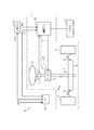
図2に示すように、操舵ECU10は、マイコン20と、カウンタ回路21と、電源回路22と、ダイアグ23と、通信インターフェース(以下、「I/F」という)24と、角度センサ25とを備えている。なお、マイコン20は制御部及び判定部の一例である。また、ダイアグ23は異常判定記録部の一例である。また、角度センサ25は検出部の一例である。
Next, the electrical configuration of the steering device 1 will be described.
As shown in FIG. 2, the steering ECU 10 includes a microcomputer 20, a counter circuit 21, a power supply circuit 22, a diagnosis 23, a communication interface (hereinafter referred to as “I / F”) 24, and an angle sensor 25. ing. The microcomputer 20 is an example of a control unit and a determination unit. The diagnosis 23 is an example of an abnormality determination recording unit. The angle sensor 25 is an example of a detection unit.

マイコン20は、マイクロプロセッシングユニット等からなり、モータ5への駆動電力の供給を制御する。モータ5への駆動電力の電力源は、バッテリ13の電力である。マイコン20には、電子回路やフリップフロップ等を組み合わせた論理回路をパッケージ化されて構成されるカウンタ回路21が接続されている。なお、カウンタ回路21は、所謂、ASIC(application specific integrated circuit)である。また、マイコン20には、バッテリ13から供給される電力である供給電圧を降圧して定電圧を供給する電源回路22が接続されている。バッテリ13と電源回路22との間には、バッテリ13からの電力の通電(オン)及び遮断(オフ)を切り替えるイグニッション14が設けられている。マイコン20には、イグニッション14がオンされるとIGオン信号が入力される。これにより、マイコン20は、EPS制御や自動操舵制御等の各種処理を実行することができるように起動する。また、マイコン20には、イグニッション14がオフされるとIGオフ信号が入力される。これにより、マイコン20は、EPS制御や自動操舵制御等の各種処理を中断又は終了して停止する。また、マイコン20は、IGオン信号及びIGオフ信号が入力されると、これら信号をカウンタ回路21に対して出力する。   The microcomputer 20 includes a microprocessing unit and the like, and controls the supply of driving power to the motor 5. A power source for driving power to the motor 5 is power of the battery 13. The microcomputer 20 is connected to a counter circuit 21 configured by packaging a logic circuit combining an electronic circuit, a flip-flop, and the like. The counter circuit 21 is a so-called ASIC (application specific integrated circuit). The microcomputer 20 is connected to a power supply circuit 22 that steps down a supply voltage that is power supplied from the battery 13 and supplies a constant voltage. An ignition 14 is provided between the battery 13 and the power supply circuit 22 for switching between energization (on) and interruption (off) of power from the battery 13. When the ignition 14 is turned on, an IG on signal is input to the microcomputer 20. Thereby, the microcomputer 20 is activated so that various processes such as EPS control and automatic steering control can be executed. Further, the IG OFF signal is input to the microcomputer 20 when the ignition 14 is turned OFF. Thereby, the microcomputer 20 interrupts or ends various processes such as EPS control and automatic steering control and stops. Further, when the IG on signal and the IG off signal are input, the microcomputer 20 outputs these signals to the counter circuit 21.

また、マイコン20には、操舵ECU10内において異常が生じた場合にその旨を記録するダイアグ23が接続されている。マイコン20は、操舵ECU10内において異常が生じた場合にその旨を示す異常信号Sdをダイアグ23に対して出力する。ダイアグ23には、車両の走行状態に関わる各種情報をユーザーに報知する報知部が集約されたインストルメントパネル15が接続されている。インストルメントパネル15では、ダイアグ23に操舵ECU10内において異常が生じた旨が記録されている場合、その旨が対応するランプ等の報知器を点灯や点滅させる等してユーザー(運転者)に報知される。また、ダイアグ23は、操舵ECU10内において異常が生じた旨を記録している場合、その旨を示す信号を操舵ECU10に接続される図示しない診断ツールに対して出力する。   The microcomputer 20 is connected to a diagnosis 23 for recording when an abnormality occurs in the steering ECU 10. When an abnormality occurs in the steering ECU 10, the microcomputer 20 outputs an abnormality signal Sd indicating that fact to the diagnosis 23. Connected to the diagnosis 23 is an instrument panel 15 in which a notification unit for notifying the user of various information related to the running state of the vehicle is integrated. In the instrument panel 15, when the fact that an abnormality has occurred in the steering ECU 10 is recorded in the diagnosis 23, the fact is notified to the user (driver) by turning on or blinking a corresponding indicator such as a lamp. Is done. When the diagnosis 23 records that an abnormality has occurred in the steering ECU 10, the diagnosis 23 outputs a signal indicating that fact to a diagnostic tool (not shown) connected to the steering ECU 10.

また、マイコン20には、I/F24が接続されている。I/F24には、操舵ECU10の外部、すなわち上位ECU11やナビ12から角度指令値θ*やクロックカウンタCtが入力される。角度指令値θ*やクロックカウンタCtは、I/F24を介してマイコン20に入力される。なお、ナビ12は外部装置の一例である。   In addition, an I / F 24 is connected to the microcomputer 20. An angle command value θ * and a clock counter Ct are input to the I / F 24 from the outside of the steering ECU 10, that is, from the host ECU 11 and the navigation 12. The angle command value θ * and the clock counter Ct are input to the microcomputer 20 via the I / F 24. The navigation 12 is an example of an external device.

カウンタ回路21には、バッテリ13が直結されている。すなわち、カウンタ回路21には、イグニッション14のオン及びオフに関係なく、バッテリ13から電力が常時供給されるようになっている。また、カウンタ回路21には、角度センサ25が接続されている。角度センサ25は、マイコン20にも接続されている。角度センサ25としては、MRセンサが採用されている。MRセンサは、相対回転角度θに応じてsinθ及びcosθの2つのアナログ信号を生成する。   A battery 13 is directly connected to the counter circuit 21. That is, the counter circuit 21 is always supplied with power from the battery 13 regardless of whether the ignition 14 is on or off. An angle sensor 25 is connected to the counter circuit 21. The angle sensor 25 is also connected to the microcomputer 20. An MR sensor is employed as the angle sensor 25. The MR sensor generates two analog signals of sin θ and cos θ according to the relative rotation angle θ.

次に、操舵ECU10の機能について、マイコン20及びカウンタ回路21の機能を中心に説明する。
まずマイコン20について詳しく説明する。
Next, the functions of the steering ECU 10 will be described focusing on the functions of the microcomputer 20 and the counter circuit 21.
First, the microcomputer 20 will be described in detail.

図2に示すように、上位ECU11は、車両情報θconに基づき横滑り防止装置の作動が必要な状況であることを判断する場合、同じく車両情報θconに基づき車両の挙動を制御する上で最適な角度指令値θ*を生成する目標操舵角演算を所定周期毎に実行する。そして、上位ECU11は、生成した角度指令値θ*をI/F24を介して操舵ECU10のマイコン20に所定周期毎に出力する。角度指令値θ*に基づいては、マイコン20がモータ5の動作を制御してモータ駆動させる。   As shown in FIG. 2, when the host ECU 11 determines that the operation of the skid prevention device is necessary based on the vehicle information θcon, the optimal angle for controlling the behavior of the vehicle based on the vehicle information θcon. The target steering angle calculation for generating the command value θ * is executed at predetermined intervals. Then, the host ECU 11 outputs the generated angle command value θ * to the microcomputer 20 of the steering ECU 10 at predetermined intervals via the I / F 24. Based on the angle command value θ *, the microcomputer 20 controls the operation of the motor 5 to drive the motor.

具体的に、マイコン20は、角度指令値θ*が上位ECU11から入力される毎に当該角度指令値θ*に基づきモータ5に出力させるべきモータトルクを示す操舵力(自動操舵トルク)の目標値として自動操舵トルク指令値を生成する自動操舵トルク演算を実行する。なお、自動操舵トルク指令値は、モータ5に供給する電流値を示している。   Specifically, the microcomputer 20 sets the target value of the steering force (automatic steering torque) indicating the motor torque to be output to the motor 5 based on the angle command value θ * every time the angle command value θ * is input from the host ECU 11. The automatic steering torque calculation for generating the automatic steering torque command value is executed. The automatic steering torque command value indicates a current value supplied to the motor 5.

自動操舵トルク演算において、マイコン20は、ステアリングシャフト6の多回転(実際)の回転角度(以下、「ステアリング絶対回転角度」という)が角度指令値θ*と一致するように自動操舵トルク指令値を生成する。   In the automatic steering torque calculation, the microcomputer 20 sets the automatic steering torque command value so that the multiple rotation (actual) rotation angle of the steering shaft 6 (hereinafter referred to as “steering absolute rotation angle”) matches the angle command value θ *. Generate.

マイコン20は、角度センサ25から取得される2つのアナログ信号からアークタンジェントを求めることにより相対回転角度θを算出する。また、マイコン20は、カウンタ回路21を通じて検出されるモータ5の回転軸の回転数である回転カウンタ値Crに基づきモータ5の回転軸の多回転(実際)の回転角度(以下、「モータ絶対回転角度」という)を検出する。回転カウンタ値Crは、モータ5の回転軸の基準位置に対してどちらの回転方向に1週(360°)単位で何週したかを示すものである。この場合、相対回転角度θに対して、「360°」に回転カウンタ値Crを乗算した値を加算することによって、モータ5の回転軸の回転方向とともにモータ絶対回転角度が得られる。そして、マイコン20は、モータ絶対回転角度を、モータ5とステアリングシャフト6との間に介在される減速機の減速比を考慮してステアリング絶対回転角度に換算する。   The microcomputer 20 calculates the relative rotation angle θ by obtaining the arc tangent from the two analog signals acquired from the angle sensor 25. Further, the microcomputer 20 uses the rotation counter value Cr, which is the number of rotations of the rotating shaft of the motor 5 detected through the counter circuit 21, to determine the rotation angle of the rotating shaft of the motor 5 (actual) (hereinafter referred to as “motor absolute rotation”). Angle)). The rotation counter value Cr indicates the number of weeks in one week (360 °) in which rotation direction with respect to the reference position of the rotation axis of the motor 5. In this case, by adding a value obtained by multiplying the rotation counter value Cr by “360 °” to the relative rotation angle θ, the motor absolute rotation angle is obtained together with the rotation direction of the rotation shaft of the motor 5. The microcomputer 20 converts the motor absolute rotation angle into the steering absolute rotation angle in consideration of the reduction ratio of the reduction gear interposed between the motor 5 and the steering shaft 6.

また、トルクセンサTrは、操舵トルクτをマイコン20に所定周期毎に出力する。操舵トルクτに基づいては、マイコン20がモータ5の動作を制御してモータ駆動させる。
具体的に、マイコン20は、操舵トルクτがトルクセンサTrから入力される毎に当該操舵トルクτに基づきモータ5に出力させるべきモータトルクを示す操舵力(アシストトルク)の目標値としてトルク指令値を生成するアシストトルク演算を実行する。なお、トルク指令値は、モータ5に供給する電流値を示している。
Further, the torque sensor Tr outputs the steering torque τ to the microcomputer 20 at predetermined intervals. Based on the steering torque τ, the microcomputer 20 controls the operation of the motor 5 to drive the motor.
Specifically, each time the steering torque τ is input from the torque sensor Tr, the microcomputer 20 uses a torque command value as a target value of the steering force (assist torque) indicating the motor torque to be output to the motor 5 based on the steering torque τ. Assist torque calculation for generating The torque command value indicates the current value supplied to the motor 5.

マイコン20は、自動操舵トルク指令値とトルク指令値とを用いて、これら自動操舵トルク指令値とトルク指令値とを合算したモータトルクを出力させるように、モータ5のモータ駆動を制御する。なお、マイコン20は、自動操舵制御の必要がない場合、自動操舵トルク指令値として零(ゼロ)を生成する。また、マイコン20は、EPS制御の必要がない場合、トルク指令値Tτ*として零(ゼロ)を生成する。これにより、ユーザーのステアリング操作が補助されるとともに、ステアリングシャフト6の回転速度及び回転角度(絶対回転角度)が制御される。   The microcomputer 20 controls the motor drive of the motor 5 using the automatic steering torque command value and the torque command value so as to output a motor torque obtained by adding the automatic steering torque command value and the torque command value. The microcomputer 20 generates zero as the automatic steering torque command value when automatic steering control is not necessary. Further, the microcomputer 20 generates zero as the torque command value Tτ * when there is no need for EPS control. Thereby, the steering operation of the user is assisted, and the rotation speed and rotation angle (absolute rotation angle) of the steering shaft 6 are controlled.

次に、カウンタ回路21について説明する。
図2に示すように、カウンタ回路21は、通電部30と、起動カウンタ31と、回転カウンタ32と、通信インターフェース(以下、「I/F」という)33とを備えている。なお、起動カウンタ31は起動回数計数部の一例である。
Next, the counter circuit 21 will be described.
As shown in FIG. 2, the counter circuit 21 includes an energization unit 30, a start counter 31, a rotation counter 32, and a communication interface (hereinafter referred to as “I / F”) 33. The activation counter 31 is an example of an activation number counting unit.

通電部30は、当該通電部30に接続されている角度センサ25への駆動電力の供給、すなわち通電を制御するトランジスタ等を組み合わせたスイッチ回路である。通電部30は、バッテリ13に直結されており、通電部30が起動している場合、イグニッション14のオン及びオフに関係なく、角度センサ25へ駆動電力を供給することができるようになっている。角度センサ25は、通電部30から通電があった場合に2つのアナログ信号をマイコン20及びカウンタ回路21に対して出力する。   The energization unit 30 is a switch circuit in which a driving power is supplied to the angle sensor 25 connected to the energization unit 30, that is, a transistor or the like that controls energization is combined. The energization unit 30 is directly connected to the battery 13, and can supply drive power to the angle sensor 25 regardless of whether the ignition 14 is on or off when the energization unit 30 is activated. . The angle sensor 25 outputs two analog signals to the microcomputer 20 and the counter circuit 21 when energized from the energization unit 30.

通電部30には、起動カウンタ31が接続されている。起動カウンタ31は、通電部30が起動した回数として起動カウンタ値Cmの計数とともに記憶をするフリップフロップ等を組み合わせた論理回路である。起動カウンタ値Cmは、イグニッション14がオフ時における通電部30が起動した回数を示すものであり、イグニッション14がオフ時に通電部30が起動する毎に1加算(+1)されるようにして更新される。なお、通電部30の起動は、角度センサ25と通電部30との間に電圧センサ等の検出部を設ける等して、当該検出部における通電の有無により検出される。そして、起動カウンタ31は、所定のタイミングで起動カウンタ値CmをI/F33に対して出力する。   An activation counter 31 is connected to the energization unit 30. The activation counter 31 is a logic circuit that combines a flip-flop or the like that stores the activation counter value Cm as the number of activations of the energization unit 30. The activation counter value Cm indicates the number of times the energization unit 30 is activated when the ignition 14 is off, and is updated so that 1 is added (+1) every time the energization unit 30 is activated when the ignition 14 is off. The The activation of the energization unit 30 is detected by the presence or absence of energization in the detection unit by providing a detection unit such as a voltage sensor between the angle sensor 25 and the energization unit 30. Then, the activation counter 31 outputs the activation counter value Cm to the I / F 33 at a predetermined timing.

また、回転カウンタ32は、角度センサ25が出力した2つのアナログ信号に基づき回転カウンタ値Crの計数とともに記憶をするフリップフロップ等を組み合わせた論理回路である。回転カウンタ値Crは、モータ5の回転軸の基準位置に対して、例えば、時計周りと反対方向に1週する毎に1加算(+1)され、時計周り方向に1週する毎に1減算(−1)されるようにして更新される。回転カウンタ値Crは、モータ5の回転軸の基準位置を第1象限と第4象限の境界と定める場合、第1象限から第4象限への変化が検出されると1加算され、第4象限から第1象限への変化が検出されると1減算される。そして、回転カウンタ32は、角度センサ25から2つのアナログ信号が入力される毎に回転カウンタ値CrをI/F33に対して出力する。   The rotation counter 32 is a logic circuit that combines a flip-flop and the like for storing together with the count of the rotation counter value Cr based on the two analog signals output from the angle sensor 25. For example, the rotation counter value Cr is incremented by 1 (+1) every week in the direction opposite to the clockwise direction with respect to the reference position of the rotation axis of the motor 5, and is subtracted by 1 every week in the clockwise direction ( -1) Updated as described above. The rotation counter value Cr is incremented by 1 when a change from the first quadrant to the fourth quadrant is detected when the reference position of the rotation axis of the motor 5 is defined as the boundary between the first quadrant and the fourth quadrant. When a change from 1 to the first quadrant is detected, 1 is subtracted. The rotation counter 32 outputs a rotation counter value Cr to the I / F 33 every time two analog signals are input from the angle sensor 25.

通電部30、起動カウンタ31、及び回転カウンタ32には、I/F33が接続されている。すなわち、起動カウンタ31から入力される起動カウンタ値Cmは、I/F33を介してマイコン20に対して出力される。回転カウンタ32から入力される回転カウンタ値Crは、I/F33を介してマイコン20に対して出力される。また、I/F33には、マイコン20から角度センサ25の2つのアナログ信号の取得を要求する角度要求信号Srが入力される。角度要求信号Srは、I/F33を介して通電部30に対して出力される。通電部30は、マイコン20から角度要求信号Srが入力されると、角度センサ25への通電を実行する。   An I / F 33 is connected to the energization unit 30, the start counter 31, and the rotation counter 32. That is, the activation counter value Cm input from the activation counter 31 is output to the microcomputer 20 via the I / F 33. The rotation counter value Cr input from the rotation counter 32 is output to the microcomputer 20 via the I / F 33. Further, an angle request signal Sr for requesting acquisition of two analog signals from the angle sensor 25 is input from the microcomputer 20 to the I / F 33. The angle request signal Sr is output to the energization unit 30 via the I / F 33. The energization unit 30 energizes the angle sensor 25 when the angle request signal Sr is input from the microcomputer 20.

本実施形態では、マイコン20が停止中であるイグニッション14がオフ時にステアリングホイール2(ステアリングシャフト6)が回転してしまったとしても、次にマイコン20が起動されるイグニッション14のオン時にステアリングホイール2についてステアリング絶対回転角度を算出することができるように構成されている。そのため、カウンタ回路21は、イグニッション14がオフ時であっても起動して所定の処理を実行することが可能に構成されている。この構成には、マイコン20、通電部30、起動カウンタ31、及び回転カウンタ32の機能が関わっている。   In the present embodiment, even if the steering wheel 2 (steering shaft 6) rotates when the ignition 14 in which the microcomputer 20 is stopped is turned off, the steering wheel 2 is turned on when the ignition 14 is activated next. It is comprised so that a steering absolute rotation angle can be calculated about. Therefore, the counter circuit 21 is configured to be able to start and execute a predetermined process even when the ignition 14 is off. In this configuration, functions of the microcomputer 20, the energization unit 30, the activation counter 31, and the rotation counter 32 are related.

以下、イグニッション14のオン及びオフに関わって、マイコン20、通電部30、起動カウンタ31、及び回転カウンタ32が実行する処理の流れについて説明する。
図3に示すように、マイコン20は、イグニッション14がオフに切り替えられたか否か(IGオフ?)を判定する(S10)。S10にて、マイコン20は、IGオフ信号が入力されたか否かを判定している。マイコン20は、IGオフ信号が入力されたことを判定しない場合(S10:NO)、S10の処理に戻りイグニッション14がオフに切り替えられた否かを判定する。
Hereinafter, a flow of processing executed by the microcomputer 20, the energization unit 30, the activation counter 31, and the rotation counter 32 in relation to turning on and off the ignition 14 will be described.
As shown in FIG. 3, the microcomputer 20 determines whether or not the ignition 14 is switched off (IG off?) (S10). In S10, the microcomputer 20 determines whether or not an IG off signal is input. If the microcomputer 20 does not determine that the IG off signal has been input (S10: NO), the microcomputer 20 returns to the process of S10 and determines whether or not the ignition 14 is switched off.

一方、マイコン20は、IGオフ信号が入力されたことを判定する場合(S10:YES)、I/F24を介してその時の時間情報としてナビ12からクロックカウンタCtを取得する(S20)。S20にて、マイコン20は、ナビ12から取得したクロックカウンタCtをオフ時クロックカウンタとして所定の記憶領域に記憶する。なお、オフ時クロックカウンタは、次にマイコン20が起動されるイグニッション14のオン時まで記憶保持される。   On the other hand, when determining that the IG off signal has been input (S10: YES), the microcomputer 20 acquires the clock counter Ct from the navigation 12 as time information at that time via the I / F 24 (S20). In S20, the microcomputer 20 stores the clock counter Ct acquired from the navigation 12 in a predetermined storage area as an off-time clock counter. The off-time clock counter is stored and held until the ignition 14 when the microcomputer 20 is next started is turned on.

続いて、マイコン20は、イグニッション14がオンに切り替えられたか否か(IGオン?)を判定する(S30)。S30にて、マイコン20は、IGオン信号が入力されたか否かを判定している。マイコン20は、IGオン信号が入力されたことを判定しない場合(S30:NO)、S30の処理に戻りイグニッション14がオンに切り替えられた否かを判定する。   Subsequently, the microcomputer 20 determines whether or not the ignition 14 is switched on (IG on?) (S30). In S30, the microcomputer 20 determines whether or not an IG ON signal is input. If the microcomputer 20 does not determine that the IG ON signal has been input (S30: NO), the microcomputer 20 returns to the process of S30 and determines whether or not the ignition 14 is switched on.

ここで、マイコン20によってイグニッション14がオンに切り替えられたことが判定される(S30:YES)までの間について説明する。
S20にて、マイコン20は、IGオフ信号をカウンタ回路21、すなわちI/F33を介して通電部30及び起動カウンタ31に対して出力もする。通電部30は、マイコン20からIGオフ信号が入力されると、マイコン20からの角度要求信号Srの有無に関係なく、予め定めた周期で起動して角度センサ25への通電を実行する間欠動作を開始する。通電部30の間欠動作によっては、角度センサ25に間欠的に通電が実行されるようになり、角度センサ25から回転カウンタ32に対して間欠的に2つのアナログ信号が入力されるようになる。そして、回転カウンタ32は、角度センサ25から間欠的に入力される2つのアナログ信号に基づき、回転カウンタ値Crの更新を実行する。また、起動カウンタ31は、マイコン20からIGオフ信号が入力されると、起動カウンタ値Cmのカウントを開始する。この場合、起動カウンタ31は、例えば、起動カウンタ値Cmを零(ゼロ)に初期化する等して、起動カウンタ値Cmを計数できる準備処理を実行する。
Here, a period until it is determined that the ignition 14 is switched on by the microcomputer 20 (S30: YES) will be described.
In S20, the microcomputer 20 also outputs an IG off signal to the energization unit 30 and the activation counter 31 via the counter circuit 21, that is, the I / F 33. When the IG OFF signal is input from the microcomputer 20, the energization unit 30 is activated at a predetermined cycle to perform energization to the angle sensor 25 regardless of the presence or absence of the angle request signal Sr from the microcomputer 20. To start. Depending on the intermittent operation of the energization unit 30, the angle sensor 25 is energized intermittently, and two analog signals are intermittently input from the angle sensor 25 to the rotation counter 32. Then, the rotation counter 32 updates the rotation counter value Cr based on the two analog signals intermittently input from the angle sensor 25. The activation counter 31 starts counting the activation counter value Cm when an IG off signal is input from the microcomputer 20. In this case, the activation counter 31 executes a preparation process that can count the activation counter value Cm, for example, by initializing the activation counter value Cm to zero (zero).

S20の処理を経てイグニッション14がオフとなった後、通電部30は、イグニッション14がオフ時の1回目の起動において角度センサ25への通電を実行する(S21)。この場合、起動カウンタ31は、S21における通電部30の起動を検出し、起動カウンタ値Cmを1加算(カウンタ+1)して更新する(S22)。S22にて、起動カウンタ31は、起動カウンタ値Cmに「1」を示す情報を記憶している。起動カウンタ値Cmが「1」を示す情報は、イグニッション14がオフ時に通電部30が1回起動したことを示している。   After the ignition 14 is turned off through the processing of S20, the energization unit 30 energizes the angle sensor 25 at the first activation when the ignition 14 is off (S21). In this case, the activation counter 31 detects activation of the energization unit 30 in S21, and updates the activation counter value Cm by adding 1 (counter + 1) (S22). In S22, the activation counter 31 stores information indicating “1” as the activation counter value Cm. Information indicating that the activation counter value Cm is “1” indicates that the energization unit 30 is activated once when the ignition 14 is off.

続いて、通電部30は、時間を空けてイグニッション14がオフ時の2回目の起動において角度センサ25への通電を実行する(S23)。この場合、起動カウンタ31は、S23における通電部30の起動を検出し、起動カウンタ値Cmを1加算(カウンタ+1)して更新する(S24)。S24にて、起動カウンタ31は、起動カウンタ値Cmに「2」を示す情報を記憶している。起動カウンタ値Cmが「2」を示す情報は、イグニッション14がオフ時に通電部30が2回起動したことを示している。   Subsequently, the energization unit 30 energizes the angle sensor 25 in the second activation when the ignition 14 is off after a time interval (S23). In this case, the activation counter 31 detects activation of the energization unit 30 in S23, and updates the activation counter value Cm by adding 1 (counter + 1) (S24). In S24, the activation counter 31 stores information indicating “2” as the activation counter value Cm. The information indicating that the activation counter value Cm is “2” indicates that the energization unit 30 has been activated twice when the ignition 14 is off.

その後、通電部30は、イグニッション14がオフ時の間、間欠的に起動して角度センサ25への通電を繰り返し実行する。また、起動カウンタ31は、通電部30が間欠的に起動する毎に起動カウンタ値Cmの更新を繰り返し実行する。また、この間においては、回転カウンタ32によって回転カウンタ値Crの更新が実行されている。   Thereafter, the energization unit 30 is activated intermittently while the ignition 14 is off, and repeatedly energizes the angle sensor 25. The activation counter 31 repeatedly updates the activation counter value Cm every time the energization unit 30 is activated intermittently. During this time, the rotation counter value Cr is updated by the rotation counter 32.

そして、マイコン20は、IGオン信号が入力されたことを判定する場合(S30:YES)、I/F24を介してその時の時間情報としてナビ12からクロックカウンタCtを取得する(S40)。S40にて、マイコン20は、ナビ12から取得したクロックカウンタCtをオン時クロックカウンタとして所定の記憶領域に記憶する。   If the microcomputer 20 determines that the IG ON signal has been input (S30: YES), the microcomputer 20 acquires the clock counter Ct from the navigation 12 through the I / F 24 as time information at that time (S40). In S40, the microcomputer 20 stores the clock counter Ct acquired from the navigation 12 in a predetermined storage area as an on-time clock counter.

S30にて、マイコン20は、IGオン信号をカウンタ回路21、すなわちI/F33を介して通電部30及び起動カウンタ31に対して出力もする。通電部30は、マイコン20からIGオン信号が入力されると、上記間欠動作を終了する。その後、通電部30によっては、マイコン20からの角度要求信号Srが入力される場合に角度センサ25に通電が実行されるようになる。また、起動カウンタ31は、マイコン20からIGオン信号が入力されると、起動カウンタ値Cmのカウントを終了する。この場合、起動カウンタ31は、その時の起動カウンタ値CmをI/F33を介してマイコン20に対して出力する。   In S30, the microcomputer 20 also outputs an IG ON signal to the energizing unit 30 and the activation counter 31 via the counter circuit 21, that is, the I / F 33. When the IG ON signal is input from the microcomputer 20, the energization unit 30 ends the intermittent operation. Thereafter, depending on the energization unit 30, the angle sensor 25 is energized when the angle request signal Sr from the microcomputer 20 is input. Further, the activation counter 31 ends the counting of the activation counter value Cm when the IG ON signal is input from the microcomputer 20. In this case, the activation counter 31 outputs the activation counter value Cm at that time to the microcomputer 20 via the I / F 33.

マイコン20は、起動カウンタ31から起動カウンタ値Cmを取得し(S50)、イグニッション14がオフされてからオンされるまでの期間である実際にオフされていたオフ時間と、イグニッション14が実際にオフされていた間に通電部30が起動した起動回数とから判定値を算出する(S60)。S60にて、マイコン20は、S20で取得して記憶したオフ時クロックカウンタと、S40で取得して記憶したオン時クロックカウンタとの差分からイグニッション14が実際にオフされていたオフ時間を算出する。そして、S60にて、マイコン20は、S50で取得した起動カウンタ値をイグニッション14がオフされていた間に通電部30が起動した起動回数とし、起動回数でオフ時間を除算することによって判定値を算出する。判定値は、イグニッション14がオフされていた間において推定される通電部30の動作の周期を示している。   The microcomputer 20 acquires the activation counter value Cm from the activation counter 31 (S50), and the off time that is the period from when the ignition 14 is turned off to when it is turned on, and when the ignition 14 is actually off. A determination value is calculated from the number of times the energization unit 30 has been activated while the current is being performed (S60). In S60, the microcomputer 20 calculates the off time during which the ignition 14 is actually turned off from the difference between the off-time clock counter acquired and stored in S20 and the on-time clock counter acquired and stored in S40. . In S60, the microcomputer 20 sets the activation counter value acquired in S50 as the number of activations that the energization unit 30 has activated while the ignition 14 is off, and divides the off time by the number of activations to determine the determination value. calculate. The determination value indicates the cycle of the operation of the energization unit 30 estimated while the ignition 14 is off.

図4(a)に示すように、マイコン20は、S60で算出した判定値を用いて、通電部30の間欠操舵が異常であるか否かを判定する(S70)。S70にて、マイコン20は、予め定められた上限閾値α及び下限閾値βの間の正常範囲に、S60で算出した判定値が含まれるか否かを判定する。マイコン20は、正常範囲に判定値が含まれている場合、通電部30の間欠動作が異常でなく正常であることを判定する。一方、マイコン20は、正常範囲に判定値が含まれていない(上限閾値αよりも判定値が大きい又は下限閾値βよりも判定値が小さい)場合、通電部30の間欠動作が異常であることを判定する。   As shown to Fig.4 (a), the microcomputer 20 determines whether the intermittent steering of the electricity supply part 30 is abnormal using the determination value calculated by S60 (S70). In S70, the microcomputer 20 determines whether or not the determination value calculated in S60 is included in the normal range between the predetermined upper limit threshold α and lower limit threshold β. When the determination value is included in the normal range, the microcomputer 20 determines that the intermittent operation of the energization unit 30 is normal and not abnormal. On the other hand, when the microcomputer 20 does not include the determination value in the normal range (the determination value is larger than the upper limit threshold α or the determination value is smaller than the lower limit threshold β), the intermittent operation of the energization unit 30 is abnormal. Determine.

なお、上限閾値α及び下限閾値βの間の正常範囲は、間欠動作によって通電部30が動作する周期が考慮され、バッテリ13の電力消費を低減させることができるとして経験的に求められる値(範囲)が設定される。特に上限閾値αは、回転カウンタ32によってモータ5の回転軸の1回転がカウントされない、回転カウンタ値Crの読み飛ばしが生じないとして経験的に求められる値が設定される。   Note that the normal range between the upper threshold value α and the lower threshold value β is a value (range) that is empirically obtained by considering the cycle in which the energization unit 30 operates by intermittent operation and can reduce the power consumption of the battery 13. ) Is set. In particular, the upper threshold value α is set to a value empirically determined that one rotation of the rotation shaft of the motor 5 is not counted by the rotation counter 32 and that the rotation counter value Cr is not skipped.

本実施形態の判定値は、大きい値であるほどイグニッション14がオフされていた間において推定される通電部30の動作する周期が長いことを示し、上限閾値αよりも大きければ回転カウンタ値Crの読み飛ばしが生じる可能性があることを推定することができる。また、本実施形態の判定値は、小さい値であるほどイグニッション14がオフされていた間において推定される通電部30の動作する周期が短いことを示し、下限閾値βよりも小さければバッテリ13の電力消費を低減させることができなくなっていることを推定することができる。これらの場合、通電部30の間欠動作が異常であることを推定することができる。   The determination value of the present embodiment indicates that the larger the value is, the longer the operation period of the energization unit 30 estimated while the ignition 14 is off, and the rotation counter value Cr is greater than the upper limit threshold α. It can be estimated that skipping may occur. Moreover, the determination value of the present embodiment indicates that the smaller the value is, the shorter the operating period of the energization unit 30 estimated while the ignition 14 is turned off. If the determination value is smaller than the lower limit threshold β, the battery 13 It can be estimated that power consumption cannot be reduced. In these cases, it can be estimated that the intermittent operation of the energization unit 30 is abnormal.

S70にて、マイコン20は、通電部30の間欠動作が異常でなく正常であることを判定する場合(S70:NO)、S10の処理に戻りイグニッション14がオフに切り替えられた否かを判定する。一方、マイコン20は、通電部30の間欠動作が異常であることを判定する場合(S70:YES)、例えばイグニッション14がオフ時の通電部30の動作を制限する、イグニッション14がオンされた直後については自動操舵制御の実行を制限する等のフェイルセーフ制御を実行する。この場合、マイコン20は、通電部30の間欠動作が異常であることを示す異常信号Sdをダイアグ23に対して出力する。   In S70, when the microcomputer 20 determines that the intermittent operation of the energizing unit 30 is not abnormal but normal (S70: NO), the microcomputer 20 returns to the process of S10 and determines whether or not the ignition 14 is switched off. . On the other hand, when the microcomputer 20 determines that the intermittent operation of the energization unit 30 is abnormal (S70: YES), for example, immediately after the ignition 14 is turned on, which restricts the operation of the energization unit 30 when the ignition 14 is off. For the above, fail-safe control such as limiting the execution of automatic steering control is executed. In this case, the microcomputer 20 outputs an abnormality signal Sd indicating that the intermittent operation of the energization unit 30 is abnormal to the diagnosis 23.

以上に説明した本実施形態によれば、以下に示す作用及び効果を奏する。
(1)マイコン20は、イグニッション14がオフ時でも動作可能なナビ12から入力されるクロックカウンタCtに基づきイグニッション14がオフ時、実際にオフされていたオフ時間を算出するようにしている。そして、マイコン20は、通電部30の間欠動作の異常を判定するためにオフ時間と組み合わせて用いるパラメータとして、イグニッション14がオフ時に通電部30が間欠動作によって起動した起動回数を用いるようにしている。
According to the present embodiment described above, the following operations and effects are achieved.
(1) The microcomputer 20 calculates an off time that is actually off when the ignition 14 is off based on the clock counter Ct input from the navigation 12 that can operate even when the ignition 14 is off. Then, the microcomputer 20 uses, as a parameter used in combination with the off time in order to determine an abnormality of the intermittent operation of the energization unit 30, the number of times that the energization unit 30 is activated by the intermittent operation when the ignition 14 is off. .

例えば、図4(b)に示すように、オフ時間Taに対して起動回数が著しく多い場合、通電部30の動作が想定していた間欠動作と比較して短周期であって、常時動作に近いと言うことができる。これは、判定値が下限閾値βよりも小さい例である。この場合、通電部30の動作が想定していた間欠動作での電力消費と比較して消費量が大きいこととなり、通電部30の間欠動作に異常が生じている可能性がある。   For example, as shown in FIG. 4 (b), when the number of activations is remarkably large with respect to the off time Ta, the operation of the energization unit 30 has a short cycle compared to the assumed intermittent operation, and the operation is always performed. It can be said that it is close. This is an example in which the determination value is smaller than the lower limit threshold β. In this case, the amount of consumption is large compared to the power consumption in the intermittent operation that the operation of the energization unit 30 is supposed to be, and there is a possibility that the intermittent operation of the energization unit 30 is abnormal.

本実施形態のマイコン20は、上記例示の状況をS60で算出する判定値を用いて好適に検出することができる。したがって、イグニッション14がオフ時、通電部30の間欠動作に異常が生じていることによって電力消費が大きくなってしまっても、これを好適に検出することができ、バッテリ13の劣化を抑制することができる。   The microcomputer 20 of the present embodiment can suitably detect the above-described exemplary situation using the determination value calculated in S60. Accordingly, when the ignition 14 is off, even if the power consumption increases due to an abnormality in the intermittent operation of the energization unit 30, this can be suitably detected and the deterioration of the battery 13 is suppressed. Can do.

また、図4(c)に示すように、オフ時間Taに対して起動回数が著しく少ない場合、通電部30の動作が想定していた間欠動作と比較して長周期であって、動作間隔が大きすぎると言うことができる。これは、判定値が上限閾値αよりも大きい例である。この場合、通電部30の動作が想定していた間欠動作と比較して長いこととなり、回転カウンタ値Crの読み飛ばしが生じる可能性がある。本実施形態のマイコン20は、イグニッション14がオフ時、回転カウンタ値Crの読み飛ばしが生じる可能性があっても、これを好適に検出することができ、モータ5の回転軸の回転角度に関する情報の信頼性を高めることができる。   In addition, as shown in FIG. 4C, when the number of times of activation is remarkably small with respect to the off time Ta, the operation of the energization unit 30 is longer than the intermittent operation assumed, and the operation interval is long. It can be said that it is too big. This is an example in which the determination value is larger than the upper threshold value α. In this case, the operation of the energization unit 30 is longer than the intermittent operation assumed, and there is a possibility that the rotation counter value Cr is skipped. The microcomputer 20 of the present embodiment can suitably detect even if there is a possibility that the rotation counter value Cr is skipped when the ignition 14 is off, and information on the rotation angle of the rotation shaft of the motor 5. Can improve the reliability.

(2)マイコン20は、S60で算出した判定値を用いて、通電部30の間欠動作が異常であるか否かを判定する(S70)。この場合、正常範囲を規定する上限閾値α及び下限閾値βを変更するだけで、通電部30の間欠動作の正常又は異常の範囲を容易に変更することができるようになる。すなわち、操舵ECU10の搭載先の仕様に応じた異常を好適に検出することができる。   (2) The microcomputer 20 determines whether the intermittent operation of the energization unit 30 is abnormal using the determination value calculated in S60 (S70). In this case, it is possible to easily change the normal or abnormal range of the intermittent operation of the energization unit 30 only by changing the upper limit threshold α and the lower limit threshold β that define the normal range. That is, it is possible to suitably detect an abnormality according to the specification of the mounting destination of the steering ECU 10.

(3)マイコン20によって通電部30の間欠動作が異常である旨が判定された場合、その旨がダイアグ23によって記録されているため、例えば、自動車整備場等へ車両が持ち込まれることで、適切な点検、整備を受けることができるようになる。これにより、通電部30の間欠動作が異常であることでバッテリ13の劣化が進んでしまう状況からの脱出を促進することができる。   (3) When it is determined by the microcomputer 20 that the intermittent operation of the energization unit 30 is abnormal, the fact is recorded by the diagnosis 23. Will be able to receive proper inspection and maintenance. Thereby, escape from the situation where deterioration of the battery 13 progresses because the intermittent operation of the energization unit 30 is abnormal can be promoted.

(4)本実施形態によれば、イグニッション14がオフ時において、モータ5の回転軸の回転角度を間欠的に検出するようにする場合、バッテリの電力消費を低減させることができるようになる。これにより、バッテリ13の劣化が抑制されるので、イグニッション14がオフ時において、より好適にモータ5の回転軸の回転角度を検出することができるようになり、モータ5の回転軸の回転角度に関する情報の信頼性を高めることができるようになる。したがって、モータ5の回転軸の回転角度を用いて自動操舵制御を実行する場合、その制御の信頼性を高めることができる。   (4) According to the present embodiment, when the rotation angle of the rotating shaft of the motor 5 is intermittently detected when the ignition 14 is off, the power consumption of the battery can be reduced. Thereby, since the deterioration of the battery 13 is suppressed, the rotation angle of the rotation shaft of the motor 5 can be detected more suitably when the ignition 14 is off. It becomes possible to improve the reliability of information. Therefore, when automatic steering control is executed using the rotation angle of the rotation shaft of the motor 5, the reliability of the control can be improved.

なお、上記実施形態は、これを適宜変更した以下の形態にて実施することもできる。
・操舵ECU10は、ダイアグ23を備えていなくてもよい。例えば、ダイアグ23は、車両A側に備えられていてもよい。この場合、マイコン20は、車両A側に備えられているダイアグ23に対して異常信号Sdを出力可能に構成されていればよい。また、操舵ECU10がダイアグ23を備えていなくても、通電部30の間欠動作が異常の場合、その旨がユーザーに対して報知されるように構成されていればよい。
In addition, the said embodiment can also be implemented with the following forms which changed this suitably.
The steering ECU 10 may not include the diagnosis 23. For example, the diagnosis 23 may be provided on the vehicle A side. In this case, the microcomputer 20 only needs to be configured to output the abnormality signal Sd to the diagnosis 23 provided on the vehicle A side. Further, even if the steering ECU 10 does not include the diagnosis 23, it may be configured so that the user is notified when the intermittent operation of the energization unit 30 is abnormal.

・マイコン20は、オフ時間と起動回数に対する通電部30の間欠動作に異常があるか否かの関係を予め把握していることで、オフ時間と起動回数とから通電部30の間欠動作に異常があるか否かを判定することができるように構成されていてもよい。   The microcomputer 20 knows in advance whether there is an abnormality in the intermittent operation of the energizing unit 30 with respect to the off time and the number of activations, so that the intermittent operation of the energizing unit 30 is abnormal from the off time and the number of activations. It may be configured to be able to determine whether or not there is.

・マイコン20は、通電部30の間欠動作に異常があるか否かを判定するための情報として、少なくとも下限閾値βを設定しればよく、上限閾値αを設定していなくてもよい。すなわち、S70にて、マイコン20は、判定値が下限閾値β以上の場合、通電部30の間欠動作が正常であることを判定する。一方、マイコン20は、判定値が下限閾値βよりも小さい場合、通電部30の間欠動作が異常であることを判定する。   The microcomputer 20 may set at least the lower limit threshold β as information for determining whether or not the intermittent operation of the energization unit 30 is abnormal, and may not set the upper limit threshold α. That is, in S70, the microcomputer 20 determines that the intermittent operation of the energization unit 30 is normal when the determination value is equal to or greater than the lower limit threshold β. On the other hand, when the determination value is smaller than the lower limit threshold β, the microcomputer 20 determines that the intermittent operation of the energization unit 30 is abnormal.

・通電部30の間欠動作の異常を判定するためにオフ時間と組み合わせて用いるパラメータとして、バッテリ13の電力消費量を用いるようにしてもよい。この場合、S20及びS40にて、マイコン20は、クロックカウンタCtを取得する替わりにその時のバッテリ13の残量を取得するように構成すればよい。そして、マイコン20は、オフ時間とバッテリ13の電力消費量とに基づき通電部30の間欠動作の異常を判定するようにすればよい。本変形例では、例えば、オフ時間の間もバッテリ13の電力消費量に基づき算出される判定値を用いるようにしてもよい。   The power consumption of the battery 13 may be used as a parameter used in combination with the off time in order to determine an abnormality in the intermittent operation of the energization unit 30. In this case, in S20 and S40, the microcomputer 20 may be configured to acquire the remaining amount of the battery 13 at that time instead of acquiring the clock counter Ct. Then, the microcomputer 20 may determine the abnormality of the intermittent operation of the energization unit 30 based on the off time and the power consumption of the battery 13. In this modification, for example, a determination value calculated based on the power consumption of the battery 13 may be used even during the off time.

・オフ時間を算出するための情報は、イグニッション14がオフ時に動作している外部装置であれば、他の装置に変更してもよい。例えば、ユーザーが携帯機を持っていることで車両Aのドアやトランクの施錠及び開錠や内燃機関(エンジン)の始動等を行えるようにするための車載機(又は携帯機)、盗難防止装置(所謂、イモビライザー)、車載の時計(電波時計)等であってもよい。   The information for calculating the off time may be changed to another device as long as it is an external device operating when the ignition 14 is off. For example, an in-vehicle device (or a portable device), an anti-theft device for enabling the user to lock and unlock the door and trunk of the vehicle A, start an internal combustion engine (engine), etc. by holding the portable device (A so-called immobilizer), an on-vehicle clock (radio clock), and the like may be used.

・オフ時間を算出するための情報は、他の装置でオフ時間を用いているECUや外部装置があれば、当該ECUや外部装置から取得されるようにしてもよい。
・角度センサ25は、操舵ECU10の外部に設けられていてもよい。
The information for calculating the off time may be acquired from the ECU or the external device if there is an ECU or an external device using the off time in another device.
The angle sensor 25 may be provided outside the steering ECU 10.

・カウンタ回路21に備えられる通電部30と、起動カウンタ31と、回転カウンタ32とは、パッケージ化されていなくてもよく、それぞれ別個に設けられていてもよい。また、カウンタ回路21は、マイクロプロセッシングユニット等からなるマイコンによって実現してもよい。   The energization unit 30, the activation counter 31, and the rotation counter 32 included in the counter circuit 21 may not be packaged and may be provided separately. The counter circuit 21 may be realized by a microcomputer including a microprocessing unit.

・通電部30の間欠動作が異常の場合、その旨がユーザーに対して報知されるように構成されていなくてもよい。
・モータ5の回転軸の回転角度を用いた制御として、例えば、EPS制御におけるハンドル戻し制御や、アシストトルクの各種補償を採用するようにしてもよい。
When the intermittent operation of the energization unit 30 is abnormal, it may not be configured to notify the user to that effect.
As the control using the rotation angle of the rotation shaft of the motor 5, for example, steering wheel return control in EPS control or various assist torque compensations may be employed.

・本実施形態は、モータ5の回転軸の回転角度を検出して制御を実行する操舵ECU10に限らず、イグニッション14がオフ時に周期的に動作する対象を有するECUに対して適用することもできる。   The present embodiment is not limited to the steering ECU 10 that detects the rotation angle of the rotating shaft of the motor 5 and executes control, but can also be applied to an ECU having an object that operates periodically when the ignition 14 is off. .

・角度センサ25としてMRセンサを用いたが、ホールセンサを用いてもよく、レゾルバを用いてもよい。
・角度センサ25では、ステアリングシャフト6の回転角度を検出するようにしたり、ラックアンドピニオン機構7におけるピニオンシャフトの回転角度を検出したりするようにしてもよい。
-Although the MR sensor was used as the angle sensor 25, a Hall sensor may be used and a resolver may be used.
The angle sensor 25 may detect the rotation angle of the steering shaft 6 or detect the rotation angle of the pinion shaft in the rack and pinion mechanism 7.

10…操舵ECU、12…ナビ、13…バッテリ、14…イグニッション、20…マイコン、21…カウンタ回路、23…ダイアグ、25…角度センサ、30…通電部、31…起動カウンタ。   DESCRIPTION OF SYMBOLS 10 ... Steering ECU, 12 ... Navi, 13 ... Battery, 14 ... Ignition, 20 ... Microcomputer, 21 ... Counter circuit, 23 ... Diag, 25 ... Angle sensor, 30 ... Current supply part, 31 ... Start-up counter

Claims (5)

バッテリからの電力の通電及び遮断を切り替えるイグニッションが前記遮断を示すオフ時に間欠動作することによって通電を間欠的に制御する通電部と、
前記イグニッションが前記通電を示すオン時に処理を実行する制御部と、を備え、
前記制御部は、前記イグニッションがオフ時でも動作可能な外部装置から入力される信号に基づき算出される前記イグニッションがオフされてからオンされるまでの期間であるオフ時間に基づき前記通電部の間欠動作の異常を判定する判定部を有している制御装置。
An energization unit that intermittently controls energization by intermittently operating when an ignition that switches between energization and interruption of electric power from the battery indicates the interruption; and
A control unit that executes processing when the ignition is turned on to indicate the energization, and
The control unit is configured to perform intermittent operation of the energization unit based on an off time that is a period from when the ignition is turned off to when the ignition is turned on, which is calculated based on a signal input from an external device operable even when the ignition is off. The control apparatus which has the determination part which determines abnormality of operation | movement.
前記イグニッションがオフ時に前記通電部が間欠動作によって起動した起動回数を計数する起動回数計数部をさらに備え、
前記判定部は、前記オフ時間の間に前記起動回数計数部によって計数される前記起動回数に基づき前記通電部の間欠動作の異常を判定する請求項1に記載の制御装置。
An activation number counting unit that counts the number of activations of the energization unit activated by intermittent operation when the ignition is off;
The control device according to claim 1, wherein the determination unit determines an abnormality in intermittent operation of the energization unit based on the number of activations counted by the activation number counting unit during the off time.
前記判定部は、前記オフ時間の間に前記起動回数計数部によって計数される前記起動回数に基づき算出される判定値が予め定めた正常範囲を逸脱しているか否かに基づき前記通電部の間欠動作が異常である旨を判定する請求項2に記載の制御装置。   The determination unit determines whether the determination value calculated based on the number of activations counted by the activation number counting unit during the off time is out of a predetermined normal range. The control device according to claim 2, wherein it is determined that the operation is abnormal. 前記判定部によって前記通電部の間欠動作が異常である旨が判定された場合に、その旨を記録する異常判定記録部をさらに備えている請求項1〜請求項3のうちいずれか一項に記載の制御装置。   The abnormality determination recording part which records that when the determination part determines that the intermittent operation | movement of the said electricity supply part is abnormal is further provided in any one of Claims 1-3. The control device described. バッテリからの電力が通電されることに基づき回転体の回転に応じて変化する物理量を検出する検出部をさらに備え、
前記通電部は、前記イグニッションがオフ時、前記検出部に対する通電を間欠的に実行し、
前記制御部は、前記イグニッションがオン時、前記検出部の検出結果に基づき前記回転体の回転角度を算出し、当該算出した回転角度を用いた制御を実行するものである請求項1〜請求項4のうちいずれか一項に記載の制御装置。
A detection unit that detects a physical quantity that changes in accordance with rotation of the rotating body based on energization of power from the battery;
The energization unit intermittently energizes the detection unit when the ignition is off,
The said control part calculates the rotation angle of the said rotary body based on the detection result of the said detection part when the said ignition is ON, and performs control using the calculated rotation angle. 4. The control device according to claim 1.
JP2016004501A 2016-01-13 2016-01-13 Control device Pending JP2017124710A (en)

Priority Applications (1)

Application Number Priority Date Filing Date Title
JP2016004501A JP2017124710A (en) 2016-01-13 2016-01-13 Control device

Applications Claiming Priority (1)

Application Number Priority Date Filing Date Title
JP2016004501A JP2017124710A (en) 2016-01-13 2016-01-13 Control device

Publications (1)

Publication Number Publication Date
JP2017124710A true JP2017124710A (en) 2017-07-20

Family

ID=59363640

Family Applications (1)

Application Number Title Priority Date Filing Date
JP2016004501A Pending JP2017124710A (en) 2016-01-13 2016-01-13 Control device

Country Status (1)

Country Link
JP (1) JP2017124710A (en)

Cited By (6)

* Cited by examiner, † Cited by third party
Publication number Priority date Publication date Assignee Title
JP2019196971A (en) * 2018-05-09 2019-11-14 株式会社ジェイテクト Angle computation device
JP2019203749A (en) * 2018-05-22 2019-11-28 株式会社ジェイテクト Angle computing device
EP3628570A1 (en) 2018-09-28 2020-04-01 Jtekt Corporation Rotation detection device
CN111344213A (en) * 2017-11-17 2020-06-26 三菱电机株式会社 Rotation detecting device
JP2020201136A (en) * 2019-06-11 2020-12-17 ファナック株式会社 Position detection device
CN113169699A (en) * 2019-02-20 2021-07-23 株式会社日立高新技术 Control system and automatic analyzer equipped with the same

Cited By (10)

* Cited by examiner, † Cited by third party
Publication number Priority date Publication date Assignee Title
CN111344213A (en) * 2017-11-17 2020-06-26 三菱电机株式会社 Rotation detecting device
CN111344213B (en) * 2017-11-17 2023-10-27 三菱电机株式会社 Rotation detection device
JP2019196971A (en) * 2018-05-09 2019-11-14 株式会社ジェイテクト Angle computation device
JP2019203749A (en) * 2018-05-22 2019-11-28 株式会社ジェイテクト Angle computing device
JP7225567B2 (en) 2018-05-22 2023-02-21 株式会社ジェイテクト angle calculator
EP3628570A1 (en) 2018-09-28 2020-04-01 Jtekt Corporation Rotation detection device
US11352048B2 (en) 2018-09-28 2022-06-07 Jtekt Corporation Rotation detection device
CN113169699A (en) * 2019-02-20 2021-07-23 株式会社日立高新技术 Control system and automatic analyzer equipped with the same
JP2020201136A (en) * 2019-06-11 2020-12-17 ファナック株式会社 Position detection device
JP7324060B2 (en) 2019-06-11 2023-08-09 ファナック株式会社 Position detector

Similar Documents

Publication Publication Date Title
JP2017124710A (en) Control device
US9623900B2 (en) Vehicle steering device, failure determination method for vehicle steering device, and control method for steering motor
JP4875724B2 (en) vehicle
US8967321B2 (en) Electric power steering apparatus
JP5339094B2 (en) Electric power steering device
JP2017196991A (en) Steering control device
JP4139157B2 (en) Vehicle steering control system
JP4027339B2 (en) Electric power steering device
EP3789270B1 (en) Control circuit and motor control device
JP6885171B2 (en) Vehicle control device
JP2019196971A (en) Angle computation device
JP2018008652A (en) Steering device
JP5867287B2 (en) Steering angle detection device for vehicle and electric power steering device
JP2009143427A (en) Steering device
JP7458144B2 (en) Angle Calculation Device
JP2012103090A (en) Angle sensor and electric power steering device
JP7225567B2 (en) angle calculator
JP2014172513A (en) Electric power steering device
JP2010256131A (en) Midpoint learning method of vehicle behavior sensor and vehicle behavior detection system
JP2006143102A (en) Steering system for vehicle
JP2015143048A (en) vehicle control device
JP2015047878A (en) Electric power steering device
JP2014189115A (en) Steering angle detection device
JP2010260430A (en) Method for correcting reference point of sensor
JP2017024430A (en) Vehicular control device and motor control unit