本発明は、パチンコ機に代表される遊技機に関するものである。
The present invention relates to a gaming machine represented by a pachinko machine.
従来より、左、中、右の特別図柄を変動表示させて、遊技の当否判定結果を報知する遊技機において、特別図柄を変動表示した後に、確定停止するまでの間、仮停止させて、それぞれの図柄を揺れ変動させて、変動終了直前まで、さらに変動表示が継続するかのような期待感を強く遊技者に抱かせて遊技への期待感を持続させるように構成した遊技機が提案されている。
Conventionally, in the gaming machine that displays the left, middle, and right special symbols in a variable manner and notifies the game success / failure determination result, after the special symbols are variably displayed, it is temporarily stopped until the final stop, A game machine that is configured to maintain the expectation of the game by causing the player to have a strong sense of expectation as if the display of fluctuation continues further until just before the end of the fluctuation is proposed. ing.
特開2002−153640号公報JP 2002-153640 A
この種のパチンコ機において、揺れ変動させて表示させることにより、変動終了時の停止態様にばらつきが発生してしまい、変動停止時に遊技者に違和感を感じさせる不具合があった。
In this type of pachinko machine, there is a problem that the display of the swinging variation causes variations in the stop mode at the end of the variation, causing the player to feel uncomfortable when the variation is stopped.
本発明は、上記例示した問題点等を解決するためになされたものであり、遊技者に遊技における違和感を与えることを軽減する遊技機を提供すること。
The present invention has been made in order to solve the above-described problems and the like, and provides a gaming machine that alleviates the player from feeling uncomfortable in the game.
この目的を達成するために請求項1記載の遊技機は、抽選条件の成立に基づいて、遊技の当否判定を実行する当否判定手段と、その当否判定手段による当否判定結果を識別可能な識別情報を表示可能な表示手段とその表示手段に表示される前記識別情報を所定の設定時間が設定され、前記識別情報を一定周期で規則的な動的表示態様を繰り返して仮停止していることを示す仮停止表示態様で表示させる前記設定時間を含む仮停止期間が設定された動的表示態様で動的表示させた後に、前記当否判定結果を示す前記識別情報で表示させる表示制御手段と、を有し、前記設定時間が経過したことに基づいて、その設定時間が経過したことを前記表示制御手段に対して通知する時間管理手段と、前記時間管理手段より前記設定時間が経過したことが通知されたことに基づいて、前記仮停止表示態様の所定タイミングで表示される特定表示態様と近似する確定停止表示態様で前記識別情報を停止表示させる確定停止手段と、前記時間管理手段により前記設定時間の経過が通知されたときに、前記識別情報の仮停止表示態様が前記特定表示態様で無い場合に、前記確定停止手段による停止表示を前記特定表示態様で前記識別情報が表示されるまでの間、遅延させる遅延手段と、を有するものである。
In order to achieve this object, the gaming machine according to claim 1 is configured to identify whether or not the game is successful by determining whether or not the game is successful based on the establishment of the lottery condition, and the identification information that can identify the result of the determination by the success / failure determining means. A predetermined setting time is set for the identification information displayed on the display means and the identification information displayed on the display means, and the identification information is temporarily stopped by repeating a regular dynamic display mode at a constant cycle. Display control means for displaying the identification information indicating the determination result after dynamic display in a dynamic display mode in which a temporary stop period including the set time to be displayed is displayed in the temporary stop display mode. And a time management means for notifying the display control means that the set time has elapsed based on the set time elapses, and that the set time has elapsed from the time management means. Based on what is known, the stoppage for displaying the identification information in a fixed stop display mode similar to the specific display mode displayed at a predetermined timing of the temporary stop display mode, and the setting by the time management unit When the passage of time is notified, if the temporary stop display mode of the identification information is not the specific display mode, the stop display by the fixed stop unit is displayed until the identification information is displayed in the specific display mode. And a delay means for delaying.
請求項2記載の遊技機は、請求項1に記載の遊技機において、前記動的表示態様は、前記設定時間の経過に対応して前記特定停止表示態様で表示されるように予め設定されているものである。
The gaming machine according to claim 2 is the gaming machine according to claim 1, wherein the dynamic display mode is preset to be displayed in the specific stop display mode corresponding to the lapse of the set time. It is what.
請求項3記載の遊技機は、請求項1または2に記載の遊技機において、前記遅延手段により遅延される遅延時間は、前記仮停止表示態様の1周期以下で設定されるものである。
The gaming machine according to claim 3 is the gaming machine according to claim 1 or 2, wherein the delay time delayed by the delay means is set within one cycle of the temporary stop display mode.
請求項4記載の遊技機は、抽選条件の成立に基づいて、遊技の当否判定を実行する当否判定手段と、その当否判定手段による当否判定結果を識別可能な識別情報を表示可能な表示手段とその表示手段に表示される前記識別情報を所定の設定時間が設定され、前記識別情報を一定周期で規則的な動的表示態様を繰り返して仮停止していることを示す仮停止表示態様で表示させる前記設定時間を含む仮停止期間が設定された動的表示態様で動的表示させた後に、前記当否判定結果を示す確定停止表示態様で表示させる表示制御手段と、を有し、前記動的表示態様に設定された設定時間に対応する設定表示態様が表示されたことを通知する表示管理手段と、前記設定時間が経過したことに基づいて、その設定時間が経過したことを前記表示制御手段に対して通知する時間管理手段と、その時間管理手段より前記設定時間が経過したことが通知され、前記表示管理手段により前記設定表示態様が表示されたことが通知されたことに基づいて、前記仮停止表示態様で表示されている前記識別情報を前記確定停止表示態様で停止表示させる確定停止手段と、を有するものである。
The gaming machine according to claim 4 is a determination unit for determining whether or not the game is successful based on the establishment of the lottery condition, and a display unit capable of displaying identification information that can identify the result of the determination by the determination unit. The identification information displayed on the display means is displayed in a temporary stop display mode indicating that a predetermined set time is set and the identification information is temporarily stopped by repeating a regular dynamic display mode at a constant period. Display control means for performing dynamic display in a dynamic display mode in which a temporary stop period including the set time to be set is set, and then displaying in a fixed stop display mode indicating the success / failure determination result. Display management means for notifying that a setting display mode corresponding to the set time set in the display mode has been displayed, and the display control means indicating that the set time has elapsed based on the elapse of the set time A time management means for notification to the time management means, and the time management means notifies that the set time has elapsed, and the display management means notifies that the setting display mode is displayed. A confirmation stop means for stopping and displaying the identification information displayed in the stop display mode in the fixed stop display mode.
請求項5記載の遊技機は、請求項4に記載の遊技機において、前記確定停止手段は、前記時間管理手段より前記設定時間の経過が通知されてから所定時間が経過しても前記表示管理手段からの通知が無い場合には、強制的に前記識別情報を前記確定停止表示態様で停止表示させるものである。
The gaming machine according to claim 5 is the gaming machine according to claim 4, wherein the fixed stop means is configured to manage the display even if a predetermined time has elapsed after the elapse of the set time is notified from the time management means. When there is no notification from the means, the identification information is forcibly stopped and displayed in the fixed stop display mode.
請求項1記載の遊技機によれば、抽選条件の成立に基づいて、遊技の当否判定を実行する当否判定手段による当否判定結果を識別可能な識別情報が表示手段に表示される。その表示手段に表示される識別情報を所定の設定時間が設定され、識別情報を一定周期で規則的な動的表示態様を繰り返して仮停止していることを示す仮停止表示態様で表示させる設定時間を含む仮停止期間が設定された動的表示態様で動的表示させた後に、当否判定結果を示す識別情報で表示制御手段により表示される。
According to the gaming machine of the first aspect, based on the establishment of the lottery condition, the identification information that can identify the result of the determination by the determination unit for determining whether or not the game is correct is displayed on the display unit. A setting for displaying the identification information displayed on the display means in a temporary stop display mode in which a predetermined set time is set and the identification information is temporarily stopped by repeating a regular dynamic display mode at a constant cycle. After dynamic display is performed in a dynamic display mode in which a temporary stop period including time is set, the display control unit displays the identification information indicating the result of the determination.
設定時間が経過したことに基づいて、その設定時間が経過したことを表示制御手段に対して時間管理手段により通知される。時間管理手段より設定時間が経過したことが通知されたことに基づいて、仮停止表示態様の所定タイミングで表示される特定表示態様と近似する確定停止表示態様で確定停止手段により確定停止させる。時間管理手段により設定時間の経過が通知されたときに、識別情報の仮停止表示態様が特定表示態様で無い場合に、確定停止手段による停止表示を特定表示態様で識別情報が表示されるまでの間、遅延手段により遅延される。
Based on the elapse of the set time, the time management means notifies the display control means that the set time has elapsed. Based on the notification that the set time has passed from the time management means, the fixed stop means makes a fixed stop in the fixed stop display mode that approximates the specific display mode displayed at the predetermined timing of the temporary stop display mode. When the lapse of the set time is notified by the time management means, when the temporary stop display mode of the identification information is not the specific display mode, the stop display by the fixed stop unit is displayed until the identification information is displayed in the specific display mode. Meanwhile, it is delayed by the delay means.
これにより、識別情報を確定停止表示態様で表示させた場合に、表示態様が大きく変化する不具合を抑制できる。よって、遊技者に遊技における違和感を与えることを軽減することができるという効果がある。
Thereby, when the identification information is displayed in the fixed stop display mode, it is possible to suppress a problem that the display mode greatly changes. Therefore, there is an effect that it is possible to reduce giving the player a sense of incongruity in the game.
請求項2記載の遊技機によれば、請求項1記載の遊技機の奏する効果に加え、動的表示態様は、設定時間の経過に対応して特定停止表示態様で表示されるように予め設定されているので、設定時間が経過したタイミングで確定停止される場合に、スムーズに識別情報
を確定停止表示態様で停止させて、効率良く遊技の処理を実行できるという効果がある。
According to the gaming machine according to claim 2, in addition to the effect of the gaming machine according to claim 1, the dynamic display mode is set in advance so as to be displayed in the specific stop display mode corresponding to the elapse of the set time. Therefore, when the set time has elapsed, the identification information can be smoothly stopped in the fixed stop display mode to efficiently execute the game process.
請求項3記載の遊技機によれば、請求項1または2記載の遊技機の奏する効果に加え、遅延手段により遅延される遅延時間は、前記仮停止表示態様の1周期以下で設定されるので、遅延時間をより短くすることが可能となり、設定時間より大きく遅延されてしまう不具合を抑制できるという効果がある。
According to the gaming machine according to claim 3, in addition to the effect achieved by the gaming machine according to claim 1 or 2, the delay time delayed by the delay means is set within one cycle of the temporary stop display mode. Thus, the delay time can be further shortened, and there is an effect that it is possible to suppress a problem that the delay time is longer than the set time.
請求項4記載の遊技機によれば、抽選条件の成立に基づいて、遊技の当否判定を実行する当否判定手段による当否判定結果を識別可能な識別情報が表示手段に表示される。その表示手段に表示される識別情報を所定の設定時間が設定され、識別情報を一定周期で規則的な動的表示態様を繰り返して仮停止していることを示す仮停止表示態様で表示させる前記設定時間を含む仮停止期間が設定された動的表示態様で動的表示させた後に、当否判定結果を示す識別情報で表示制御手段により表示される。
According to the gaming machine of the fourth aspect, based on the establishment of the lottery condition, the identification information that can identify the result of the determination by the determination unit for determining whether or not the game is correct is displayed on the display unit. The identification information displayed on the display means is displayed in a temporary stop display mode in which a predetermined set time is set and the identification information is temporarily stopped by repeating a regular dynamic display mode at a constant period. After dynamic display in the dynamic display mode in which the temporary stop period including the set time is set, the display control unit displays the identification information indicating the determination result.
動的表示態様に設定された設定時間に対応する設定表示態様が表示されたことが表示管理手段により通知される。設定時間が経過したことに基づいて、その設定時間が経過したことが前記表示制御手段に対して時間管理手段により通知される。その時間管理手段より設定時間が通知され、表示管理手段により設定表示態様が表示されたことが通知されたことに基づいて、仮停止表示態様で表示されている識別情報を確定停止表示態様で確定停止手段により確定停止させる。
The display management means notifies that the setting display mode corresponding to the set time set in the dynamic display mode is displayed. Based on the elapse of the set time, the time management means notifies the display control means that the set time has elapsed. The set time is notified from the time management means, and the identification information displayed in the temporary stop display form is confirmed in the fixed stop display form based on the notification that the setting display form is displayed by the display management means. A fixed stop is made by the stopping means.
これにより、識別情報を確定停止表示態様で表示させた場合に、表示態様が大きく変化する不具合を抑制できる。よって、遊技者に遊技における違和感を与えることを軽減することができるという効果がある。
Thereby, when the identification information is displayed in the fixed stop display mode, it is possible to suppress a problem that the display mode greatly changes. Therefore, there is an effect that it is possible to reduce giving the player a sense of incongruity in the game.
請求項5記載の遊技機によれば、請求項4記載の遊技機の奏する効果に加え、次の効果を奏する。即ち、確定停止手段は、時間管理手段より設定時間の経過が通知されてから所定時間が経過しても表示管理手段からの通知が無い場合には、強制的に識別情報を確定停止表示態様で確定停止手段により停止表示される。
According to the gaming machine of the fifth aspect, in addition to the effect produced by the gaming machine according to the fourth aspect, the following effect is produced. In other words, the confirmation stop means forcibly identifies the identification information in the confirmation stop display mode when there is no notification from the display management means even after a predetermined time has passed since the time management means is notified of the passage of the set time. The stop display is made by the fixed stop means.
これにより、設定時間を大きく超過しても識別情報が確定停止されない不具合を抑制できる。よって、識別情報が確定停止されず、遊技者を混乱させる不具合を抑制できるという効果がある。
Accordingly, it is possible to suppress a problem that the identification information is not fixedly stopped even if the set time is greatly exceeded. Therefore, the identification information is not confirmed and stopped, and there is an effect that it is possible to suppress problems that confuse the player.
第1実施形態におけるパチンコ機の正面図である。It is a front view of the pachinko machine in a 1st embodiment.
第1実施形態におけるパチンコ機の遊技盤の正面図である。It is a front view of the game board of the pachinko machine in the first embodiment.
第1実施形態におけるパチンコ機の背面図である。It is a rear view of the pachinko machine in a 1st embodiment.
(a)は、第1実施形態における表示画面の領域区分設定と有効ライン設定とを模式的に示した図あり、(b)は、第1実施形態における実際の表示画面を例示した図である。(A) is the figure which showed typically the area division setting and effective line setting of the display screen in 1st Embodiment, (b) is the figure which illustrated the actual display screen in 1st Embodiment. .
(a)〜(i)は、第1実施形態における特別図柄の変動停止時の揺れ変動の流れを模式的に示した模式図である。(A)-(i) is the schematic diagram which showed typically the flow of the fluctuation fluctuation | variation at the time of the fluctuation | variation stop of the special symbol in 1st Embodiment.
(a)〜(i)は、第1実施形態における特別図柄の変動停止時の揺れ変動についての流れを詳細に示した模式図である。(A)-(i) is the schematic diagram which showed in detail the flow about the fluctuation | variation at the time of the fluctuation | variation stop of the special symbol in 1st Embodiment.
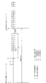
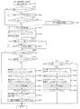
第1実施形態における特別図柄の変動パターンのタイミングチャートを示した図である。It is the figure which showed the timing chart of the fluctuation pattern of the special symbol in 1st Embodiment.
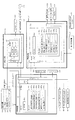
第1実施形態におけるパチンコ機の電気的構成を示すブロック図である。It is a block diagram which shows the electrical structure of the pachinko machine in 1st Embodiment.
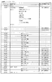
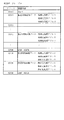
第1実施形態における各種カウンタの概要を示す図である。It is a figure which shows the outline | summary of the various counters in 1st Embodiment.
(a)は、第1実施形態における第1当たり種別カウンタC2と特別図柄における大当たり種別との対応関係を模式的に示した模式図であり、(b)は、第1実施形態における第2当たり乱数カウンタC4と普通図柄における当たりとの対応関係を模式的に示した模式図である。(A) is the schematic diagram which showed typically the correspondence of the 1st hit type counter C2 in 1st Embodiment and the jackpot type in a special symbol, (b) is 2nd hit in 1st Embodiment. It is the schematic diagram which showed typically the correspondence of the random number counter C4 and the hit in a normal symbol.
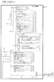
第1実施形態における表示制御装置の電気的構成を示すブロック図である。It is a block diagram which shows the electric constitution of the display control apparatus in 1st Embodiment.
第1実施形態における変動表示データテーブルの一例を模式的に示した模式図である。It is the schematic diagram which showed typically an example of the fluctuation | variation display data table in 1st Embodiment.
第1実施形態における転送データテーブルの一例を模式的に示した模式図である。It is the schematic diagram which showed typically an example of the transfer data table in 1st Embodiment.
第1実施形態における描画リストの一例を模式的に示した模式図である。It is the schematic diagram which showed typically an example of the drawing list | wrist in 1st Embodiment.
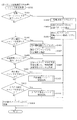
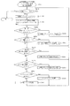
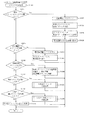
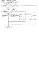
第1実施形態における主制御装置内のMPUにより実行されるタイマ割込処理を示すフローチャートである。It is a flowchart which shows the timer interruption process performed by MPU in the main controller in 1st Embodiment.
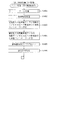
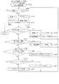
第1実施形態における主制御装置内のMPUにより実行される特別図柄変動処理を示すフローチャートである。It is a flowchart which shows the special symbol fluctuation | variation process performed by MPU in the main controller in 1st Embodiment.
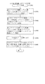
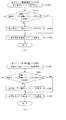
第1実施形態における主制御装置内のMPUにより実行される特別図柄変動開始処理を示したフローチャートである。It is the flowchart which showed the special symbol change start process performed by MPU in the main controller in 1st Embodiment.
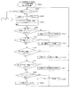
第1実施形態における主制御装置内のMPUにより実行される始動入賞処理を示すフローチャートである。It is a flowchart which shows the start winning process performed by MPU in the main controller in 1st Embodiment.
第1実施形態における主制御装置内のMPUにより実行される普通図柄変動処理を示すフローチャートである。It is a flowchart which shows the normal symbol fluctuation | variation process performed by MPU in the main controller in 1st Embodiment.
第1実施形態における主制御装置内のMPUにより実行されるスルーゲート通過処理を示すフローチャートである。It is a flowchart which shows the through gate passage process performed by MPU in the main controller in 1st Embodiment.
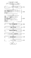
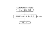
第1実施形態における主制御装置内のMPUにより実行されるNMI割込処理を示すフローチャートである。It is a flowchart which shows the NMI interruption process performed by MPU in the main controller in 1st Embodiment.
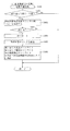
第1実施形態における主制御装置内のMPUにより実行される立ち上げ処理を示すフローチャートである。It is a flowchart which shows the starting process performed by MPU in the main controller in 1st Embodiment.
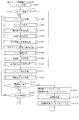
第1実施形態における主制御装置内のMPUにより実行されるメイン処理を示すフローチャートである。It is a flowchart which shows the main process performed by MPU in the main controller in 1st Embodiment.
第1実施形態における音声ランプ制御装置内のMPUにより実行される立ち上げ処理を示したフローチャートである。It is the flowchart which showed the starting process performed by MPU in the audio | voice lamp control apparatus in 1st Embodiment.
第1実施形態における音声ランプ制御装置内のMPUにより実行されるメイン処理を示したフローチャートである。It is the flowchart which showed the main process performed by MPU in the audio | voice lamp control apparatus in 1st Embodiment.
第1実施形態における音声ランプ制御装置内のMPUにより実行されるコマンド判定処理を示したフローチャートである。It is the flowchart which showed the command determination process performed by MPU in the audio | voice lamp control apparatus in 1st Embodiment.
(a)は、第1実施形態における音声ランプ制御処置内のMPUにより実行される外れ確定コマンド受信処理を示したフローチャートであり、(b)は、第1実施形態における音声ランプ制御装置内のMPUにより実行される大当たり確定コマンド受信処理を示したフローチャートである。(A) is the flowchart which showed the deviation confirmation command reception process performed by MPU in the audio | voice lamp control treatment in 1st Embodiment, (b) is MPU in the audio | voice lamp control apparatus in 1st Embodiment. 5 is a flowchart showing a jackpot confirmation command reception process executed by.
第1実施形態における音声ランプ制御装置内のMPUにより実行される変動表示設定処理を示したフローチャートである。It is the flowchart which showed the fluctuation | variation display setting process performed by MPU in the audio | voice lamp control apparatus in 1st Embodiment.
第1実施形態における表示制御装置内のMPUにより実行されるメイン処理を示したフローチャートである。It is the flowchart which showed the main process performed by MPU in the display control apparatus in 1st Embodiment.
第1実施形態における表示制御装置内のMPUにより実行されるブート処理を示すフローチャートである。It is a flowchart which shows the boot process performed by MPU in the display control apparatus in 1st Embodiment.
(a)は、第1実施形態における表示制御装置内のMPUにより実行されるコマンド割込処理を示したフローチャートであり、(b)は、第1実施形態における表示制御装置内のMPUにより実行されるV割込処理を示したフローチャートである。(A) is the flowchart which showed the command interruption process performed by MPU in the display control apparatus in 1st Embodiment, (b) is performed by MPU in the display control apparatus in 1st Embodiment. It is the flowchart which shows the V interruption processing.
第1実施形態における表示制御装置内のMPUにより実行されるコマンド判定処理を示したフローチャートである。It is the flowchart which showed the command determination process performed by MPU in the display control apparatus in 1st Embodiment.
(a)は、第1実施形態における表示制御装置内のMPUにより実行される変動パターンコマンド処理を示したフローチャートであり、(b)は、第1実施形態における表示制御装置内のMPUにより実行される停止種別コマンド処理を示したフローチャートである。(A) is the flowchart which showed the change pattern command process performed by MPU in the display control apparatus in 1st Embodiment, (b) is performed by MPU in the display control apparatus in 1st Embodiment. 5 is a flowchart showing stop type command processing.
第1実施形態における表示制御装置内のMPUにより実行されるエラーコマンド処理を示したフローチャートである。It is the flowchart which showed the error command process performed by MPU in the display control apparatus in 1st Embodiment.
第1実施形態における表示制御装置内のMPUにより実行される表示設定処理を示したフローチャートである。It is the flowchart which showed the display setting process performed by MPU in the display control apparatus in 1st Embodiment.
第1実施形態における表示制御装置内のMPUにより実行される警告画像設定処理を示したフローチャートである。It is the flowchart which showed the warning image setting process performed by MPU in the display control apparatus in 1st Embodiment.
第1実施形態における表示制御装置内のMPUにより実行されるポインタ更新処理を示したフローチャートである。It is the flowchart which showed the pointer update process performed by MPU in the display control apparatus in 1st Embodiment.
(a)は、第1実施形態における表示制御装置内のMPUにより実行される転送設定処理を示したフローチャートであり、(b)は、第1実施形態における表示制御装置内のMPUにより実行される常駐画像転送設定処理を示したフローチャートである。(A) is the flowchart which showed the transfer setting process performed by MPU in the display control apparatus in 1st Embodiment, (b) is performed by MPU in the display control apparatus in 1st Embodiment. It is the flowchart which showed the resident image transfer setting process.
第1実施形態における表示制御装置内のMPUにより実行される通常画像転送設定処理を示したフローチャートである。It is the flowchart which showed the normal image transfer setting process performed by MPU in the display control apparatus in 1st Embodiment.
第1実施形態における表示制御装置内のMPUにより実行される描画処理を示したフローチャートである。It is the flowchart which showed the drawing process performed by MPU in the display control apparatus in 1st Embodiment.
(a)は、第2実施形態における表示画面の領域区分設定と有効ライン設定とを模式的に示した図あり、(b)は、第2実施形態における実際の表示画面を例示した図である。(A) is the figure which showed typically the area division setting and effective line setting of the display screen in 2nd Embodiment, (b) is the figure which illustrated the actual display screen in 2nd Embodiment. .
(a)〜(i)は、第2実施形態における特別図柄の変動停止時の揺れ変動の流れを模式的に示した模式図である。(A)-(i) is the schematic diagram which showed typically the flow of the fluctuation fluctuation | variation at the time of the fluctuation | variation stop of the special symbol in 2nd Embodiment.
第2実施形態における特別図柄の変動パターンのタイミングチャートを示した図である。It is the figure which showed the timing chart of the fluctuation pattern of the special symbol in 2nd Embodiment.
第2実施形態におけるパチンコ機の電気的構成を示すブロック図である。It is a block diagram which shows the electrical structure of the pachinko machine in 2nd Embodiment.
第2実施形態における表示制御装置の電気的構成を示すブロック図である。It is a block diagram which shows the electric constitution of the display control apparatus in 2nd Embodiment.
第2実施形態における変動表示データテーブルの一例を模式的に示した模式図である。It is the schematic diagram which showed typically an example of the fluctuation | variation display data table in 2nd Embodiment.
第2実施形態における転送データテーブルの一例を模式的に示した模式図である。It is the schematic diagram which showed typically an example of the transfer data table in 2nd Embodiment.
第2実施形態における主制御装置内のMPUにより実行される特別図柄変動処理を示すフローチャートである。It is a flowchart which shows the special symbol fluctuation | variation process performed by MPU in the main controller in 2nd Embodiment.
第2実施形態における主制御装置内のMPUにより実行される第4確定コマンド送信処理を示すフローチャートである。It is a flowchart which shows the 4th confirmation command transmission process performed by MPU in the main controller in 2nd Embodiment.
第2実施形態における主制御装置内のMPUにより実行される特別図柄変動開始処理を示したフローチャートである。It is the flowchart which showed the special symbol change start process performed by MPU in the main controller in 2nd Embodiment.
第2実施形態における音声ランプ制御装置内のMPUにより実行されるコマンド判定処理を示したフローチャートである。It is the flowchart which showed the command determination process performed by MPU in the audio lamp control apparatus in 2nd Embodiment.
(a)は、第2実施形態における音声ランプ制御処置内のMPUにより実行される外れ確定コマンド受信処理を示したフローチャートであり、(b)は、第2実施形態における音声ランプ制御装置内のMPUにより実行される大当たり確定コマンド受信処理を示したフローチャートである。(A) is the flowchart which showed the deviation confirmation command reception process performed by MPU in the audio | voice lamp control treatment in 2nd Embodiment, (b) is MPU in the audio | voice lamp control apparatus in 2nd Embodiment. 5 is a flowchart showing a jackpot confirmation command reception process executed by.
(a)は、第2実施形態における音声ランプ制御処置内のMPUにより実行される外れ第4確定コマンド受信処理を示したフローチャートであり、(b)は、第2実施形態における音声ランプ制御装置内のMPUにより実行される大当たり第4確定コマンド受信処理を示したフローチャートである。(A) is the flowchart which showed the 4th definite command reception process performed by MPU in the audio | voice lamp control treatment in 2nd Embodiment, (b) is the inside of the audio | voice lamp control apparatus in 2nd Embodiment. It is the flowchart which showed the jackpot 4th definite command reception process performed by MPU of.
第2実施形態における表示制御装置内のMPUにより実行されるコマンド判定処理を示したフローチャートである。It is the flowchart which showed the command determination process performed by MPU in the display control apparatus in 2nd Embodiment.
第2実施形態における表示制御装置内のMPUにより実行される変動パターンコマンド処理を示したフローチャートである。It is the flowchart which showed the fluctuation pattern command process performed by MPU in the display control apparatus in 2nd Embodiment.
第2実施形態における表示制御装置内のMPUにより実行されるポインタ更新処理を示したフローチャートである。It is the flowchart which showed the pointer update process performed by MPU in the display control apparatus in 2nd Embodiment.
第3実施形態における変動表示データテーブルの一例を模式的に示した模式図である。It is the schematic diagram which showed typically an example of the fluctuation | variation display data table in 3rd Embodiment.
第3実施形態における転送データテーブルの一例を模式的に示した模式図である。It is the schematic diagram which showed typically an example of the transfer data table in 3rd Embodiment.
第3実施形態における主制御装置内のMPUにより実行される特別図柄変動処理を示すフローチャートである。It is a flowchart which shows the special symbol fluctuation | variation process performed by MPU in the main controller in 3rd Embodiment.
第3実施形態における音声ランプ制御装置内のMPUにより実行されるコマンド判定処理を示したフローチャートである。It is the flowchart which showed the command determination process performed by MPU in the audio lamp control apparatus in 3rd Embodiment.
(a)は、第3実施形態における音声ランプ制御処置内のMPUにより実行される外れ第4確定コマンド受信処理を示したフローチャートであり、(b)は、第3実施形態における音声ランプ制御装置内のMPUにより実行される大当たり第4確定コマンド受信処理を示したフローチャートである。(A) is the flowchart which showed the 4th definite command reception process performed by MPU in the audio | voice lamp control treatment in 3rd Embodiment, (b) is the inside of the audio | voice lamp control apparatus in 3rd Embodiment. It is the flowchart which showed the jackpot 4th definite command reception process performed by MPU of.
第3実施形態における表示制御装置内のMPUにより実行されるコマンド判定処理を示したフローチャートである。It is the flowchart which showed the command determination process performed by MPU in the display control apparatus in 3rd Embodiment.
第4実施形態におけるパチンコ機の遊技盤の正面図である。It is a front view of the game board of the pachinko machine in 4th Embodiment.
第4実施形態におけるパチンコ機の電気的構成を示すブロック図である。It is a block diagram which shows the electric constitution of the pachinko machine in 4th Embodiment.
第4実施形態における表示制御装置の電気的構成を示すブロック図である。It is a block diagram which shows the electric constitution of the display control apparatus in 4th Embodiment.
第4実施形態における音声ランプ制御装置内のMPUにより実行されるメイン処理を示したフローチャートである。It is the flowchart which showed the main process performed by MPU in the audio | voice lamp control apparatus in 4th Embodiment.
第4実施形態における音声ランプ制御装置内のMPUにより実行されるコマンド判定処理を示したフローチャートである。It is the flowchart which showed the command determination process performed by MPU in the audio lamp control apparatus in 4th Embodiment.
(a)は、第4実施形態における音声ランプ制御処置内のMPUにより実行される外れ確定コマンド受信処理を示したフローチャートであり、(b)は、第4実施形態における音声ランプ制御装置内のMPUにより実行される大当たり確定コマンド受信処理を示したフローチャートである。(A) is the flowchart which showed the deviation confirmation command reception process performed by MPU in the audio | voice lamp control treatment in 4th Embodiment, (b) is MPU in the audio | voice lamp control apparatus in 4th Embodiment. 5 is a flowchart showing a jackpot confirmation command reception process executed by.
第4実施形態における音声ランプ制御装置内のMPUにより実行される表示コマンド判定処理を示したフローチャートである。It is the flowchart which showed the display command determination process performed by MPU in the audio lamp control apparatus in 4th Embodiment.
(a)は、第4実施形態における音声ランプ制御処置内のMPUにより実行される外れ第4確定コマンド受信処理を示したフローチャートであり、(b)は、第4実施形態における音声ランプ制御装置内のMPUにより実行される大当たり第4確定コマンド受信処理を示したフローチャートである。(A) is the flowchart which showed the deviating 4th definite command reception process performed by MPU in the audio | voice lamp control treatment in 4th Embodiment, (b) is in the audio | voice lamp control apparatus in 4th Embodiment. It is the flowchart which showed the jackpot 4th definite command reception process performed by MPU of.
第4実施形態における表示制御装置内のMPUにより実行されるコマンド判定処理を示したフローチャートである。It is the flowchart which showed the command determination process performed by MPU in the display control apparatus in 4th Embodiment.
(a)は、第4実施形態における表示制御装置内のMPUにより実行される表示用外れ確定コマンド受信処理を示したフローチャートであり、(b)は、第4実施形態における表示制御装置内のMPUにより実行される表示用大当たり確定コマンド受信処理を示したフローチャートである。(A) is the flowchart which showed the display removal confirmation command reception process performed by MPU in the display control apparatus in 4th Embodiment, (b) is MPU in the display control apparatus in 4th Embodiment. 5 is a flowchart showing a display jackpot confirmation command reception process executed by.
(a)は、第4実施形態における表示制御装置内のMPUにより実行される表示用エラー報知1コマンド処理を示したフローチャートであり、(b)は、第4実施形態における表示制御装置内のMPUにより実行される表示用エラー報知3コマンド受信処理を示したフローチャートである。(A) is the flowchart which showed the error notification 1 command process for a display performed by MPU in the display control apparatus in 4th Embodiment, (b) is MPU in the display control apparatus in 4th Embodiment. 5 is a flowchart showing a display error notification 3 command reception process executed by.
第5実施形態における第3図柄の変動パターンのタイミングチャートを示した図である。It is the figure which showed the timing chart of the variation pattern of the 3rd pattern in 5th Embodiment.
第5実施形態における変動表示データテーブルの一例を模式的に示した模式図である。It is the schematic diagram which showed typically an example of the fluctuation | variation display data table in 5th Embodiment.
第5実施形態における転送データテーブルの一例を模式的に示した模式図である。It is the schematic diagram which showed typically an example of the transfer data table in 5th Embodiment.
第5実施形態における表示制御装置内のMPUにより実行される表示設定処理を示したフローチャートである。It is the flowchart which showed the display setting process performed by MPU in the display control apparatus in 5th Embodiment.
第6実施形態におけるパチンコ機の電気的構成を示すブロック図である。It is a block diagram which shows the electric constitution of the pachinko machine in 6th Embodiment.
第6実施形態における表示制御装置の電気的構成を示すブロック図である。It is a block diagram which shows the electric constitution of the display control apparatus in 6th Embodiment.
第6実施形態における音声ランプ制御装置内のMPUにより実行されるメイン処理を示したフローチャートである。It is the flowchart which showed the main process performed by MPU in the audio lamp control apparatus in 6th Embodiment.
第6実施形態における音声ランプ制御装置内のMPUにより実行される図柄確定処理を示したフローチャートである。It is the flowchart which showed the symbol determination process performed by MPU in the audio | voice lamp control apparatus in 6th Embodiment.
第6実施形態における音声ランプ制御装置内のMPUにより実行されるコマンド判定処理を示したフローチャートである。It is the flowchart which showed the command determination process performed by MPU in the audio lamp control apparatus in 6th Embodiment.
第6実施形態における音声ランプ制御装置内のMPUにより実行される表示コマンド判定処理を示したフローチャートである。It is the flowchart which showed the display command determination process performed by MPU in the audio lamp control apparatus in 6th Embodiment.
第6実施形態における表示制御装置内のMPUにより実行されるコマンド判定処理を示したフローチャートである。It is the flowchart which showed the command determination process performed by MPU in the display control apparatus in 6th Embodiment.
第6実施形態における表示制御装置内のMPUにより実行される表示設定処理を示したフローチャートである。It is the flowchart which showed the display setting process performed by MPU in the display control apparatus in 6th Embodiment.
第6実施形態における表示制御装置内のMPUにより実行されるポインタ更新処理を示したフローチャートである。It is the flowchart which showed the pointer update process performed by MPU in the display control apparatus in 6th Embodiment.
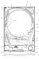
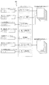
以下、本発明の第1の実施形態について、添付図面を参照して説明する。図1は、第1の実施形態におけるパチンコ機10の正面図であり、図2はパチンコ機10の遊技盤13の正面図であり、図3はパチンコ機10の背面図である。
DESCRIPTION OF EXEMPLARY EMBODIMENTS Hereinafter, a first embodiment of the invention will be described with reference to the accompanying drawings. FIG. 1 is a front view of a pachinko machine 10 according to the first embodiment, FIG. 2 is a front view of a game board 13 of the pachinko machine 10, and FIG. 3 is a rear view of the pachinko machine 10.
パチンコ機10は、図1に示すように、略矩形状に組み合わせた木枠により外殻が形成される外枠11と、その外枠11と略同一の外形形状に形成され外枠11に対して開閉可能に支持された内枠12とを備えている。外枠11には、内枠12を支持するために正面視(図1参照)左側の上下2カ所に金属製のヒンジ18が取り付けられ、そのヒンジ18が設けられた側を開閉の軸として内枠12が正面手前側へ開閉可能に支持されている。
As shown in FIG. 1, the pachinko machine 10 includes an outer frame 11 having an outer shell formed of a wooden frame combined in a substantially rectangular shape, and an outer frame 11 having substantially the same outer shape as the outer frame 11. And an inner frame 12 supported to be openable and closable. In order to support the inner frame 12, metal hinges 18 are attached to the outer frame 11 at two upper and lower portions on the left side when viewed from the front (see FIG. 1). The frame 12 is supported so as to be openable and closable to the front front side.
内枠12には、多数の釘や入賞口63,64等を有する遊技盤13(図2参照)が裏面側から着脱可能に装着される。この遊技盤13の前面を球が流下することにより弾球遊技が行われる。なお、内枠12には、球を遊技盤13の前面領域に発射する球発射ユニット112a(図8参照)やその球発射ユニット112aから発射された球を遊技盤13の前面領域まで誘導する発射レール(図示せず)等が取り付けられている。
A game board 13 (see FIG. 2) having a large number of nails, winning holes 63, 64 and the like is detachably mounted on the inner frame 12 from the back side. A ball ball game is performed when the ball flows down the front surface of the game board 13. The inner frame 12 has a ball launch unit 112a (see FIG. 8) that launches a ball to the front area of the game board 13 and a launch that guides the ball launched from the ball launch unit 112a to the front area of the game board 13. A rail (not shown) or the like is attached.
内枠12の前面側には、その前面上側を覆う前面枠14と、その下側を覆う下皿ユニット15とが設けられている。前面枠14及び下皿ユニット15を支持するために正面視(図1参照)左側の上下2カ所に金属製のヒンジ19が取り付けられ、そのヒンジ19が設けられた側を開閉の軸として前面枠14及び下皿ユニット15が正面手前側へ開閉可能に支持されている。なお、内枠12の施錠と前面枠14の施錠とは、シリンダ錠20の鍵穴21に専用の鍵を差し込んで所定の操作を行うことでそれぞれ解除される。
On the front side of the inner frame 12, a front frame 14 that covers the upper side of the front surface and a lower dish unit 15 that covers the lower side of the front frame 14 are provided. In order to support the front frame 14 and the lower dish unit 15, metal hinges 19 are attached to two upper and lower portions on the left side when viewed from the front (see FIG. 1), and the side on which the hinges 19 are provided is used as an opening / closing axis. 14 and the lower pan unit 15 are supported so as to be openable and closable toward the front front side. The locking of the inner frame 12 and the locking of the front frame 14 are respectively released by inserting a dedicated key into the key hole 21 of the cylinder lock 20 and performing a predetermined operation.
前面枠14は、装飾用の樹脂部品や電気部品等を組み付けたものであり、その略中央部には略楕円形状に開口形成された窓部14cが設けられている。前面枠14の裏面側には2枚の板ガラスを有するガラスユニット16が配設され、そのガラスユニット16を介して遊技盤13の前面がパチンコ機10の正面側に視認可能となっている。
The front frame 14 is assembled with decorative resin parts, electrical parts, and the like, and a window part 14c that is formed in an approximately elliptical shape is provided at a substantially central part thereof. A glass unit 16 having two plate glasses is disposed on the back side of the front frame 14, and the front surface of the game board 13 can be seen on the front side of the pachinko machine 10 through the glass unit 16.
前面枠14には、球を貯留する上皿17が前方へ張り出して上面を開放した略箱状に形成されており、この上皿17に賞球や貸出球などが排出される。上皿17の底面は正面視(図1参照)右側に下降傾斜して形成され、その傾斜により上皿17に投入された球が球発射ユニット112aへと案内される。また、上皿17の上面には、枠ボタン22が設けられている。この枠ボタン22は、例えば、後述する第3図柄表示装置81(図2参照)で表示される演出の背景を変更したり、スーパーリーチの演出内容を変更したりする場合などに、遊技者により操作される。
On the front frame 14, an upper plate 17 that stores balls is formed in a substantially box shape that protrudes forward and the upper surface is opened, and prize balls and rental balls are discharged to the upper plate 17. The bottom surface of the upper plate 17 is formed to be inclined downward to the right when viewed from the front (see FIG. 1), and the sphere thrown into the upper plate 17 is guided to the ball launch unit 112a by the inclination. A frame button 22 is provided on the upper surface of the upper plate 17. The frame button 22 is used by the player when, for example, the background of the effect displayed on the third symbol display device 81 (see FIG. 2) described later is changed or the content of the effect of super reach is changed. Operated.
一方、第3図柄表示装置81には、ノーマルリーチ演出が開始された場合に、ノーマルリーチからスーパーリーチに発展させるときは、ノーマルリーチ中にスーパーリーチの演出態様の選択画面が表示されるように構成されており、その選択画面が表示されている間に、枠ボタン22が遊技者に操作されると、スーパーリーチ時の演出内容が変更される。
On the other hand, the 3rd symbol display device 81 is configured to display a selection screen for a super reach effect mode during normal reach when the normal reach effect is started and the normal reach is developed to the super reach. When the frame button 22 is operated by the player while the selection screen is displayed, the contents of the effect at the time of super reach are changed.
前面枠14には、その周囲(例えばコーナー部分)に各種ランプ等の発光手段が設けられている。これら発光手段は、大当たり時や所定のリーチ時等における遊技状態の変化に応じて、点灯又は点滅することにより発光態様が変更制御され、遊技中の演出効果を高める役割を果たす。窓部14cの周縁には、LED等の発光手段を内蔵した電飾部29〜33が設けられている。パチンコ機10においては、これら電飾部29〜33が大当たりランプ等の演出ランプとして機能し、大当たり時やリーチ演出時等には内蔵するLEDの点灯や点滅によって各電飾部29〜33が点灯または点滅して、大当たり中である旨、或いは大当たり一歩手前のリーチ中である旨が報知される。また、前面枠14の正面視(図1参照)左上部には、LED等の発光手段が内蔵され賞球の払い出し中とエラー発生時とを表示可能な表示ランプ34が設けられている。
The front frame 14 is provided with light emitting means such as various lamps around it (for example, a corner portion). These light-emitting means play a role of enhancing the effect of the game during the game by changing or controlling the light-emitting mode by turning on or flashing according to the change in the gaming state at the time of big hit or predetermined reach. On the peripheral edge of the window portion 14c, there are provided electric decoration portions 29 to 33 incorporating light emitting means such as LEDs. In the pachinko machine 10, these lighting parts 29 to 33 function as effect lamps such as jackpot lamps, and the lighting parts 29 to 33 are turned on by lighting or blinking of the built-in LEDs at the time of jackpot or reach effects. Alternatively, it flashes to notify that the jackpot is being hit or that the reach is one step before the jackpot. Further, in the upper left part of the front frame 14 as viewed from the front (see FIG. 1), there is provided a display lamp 34 which has built-in light emitting means such as LEDs and can display the payout of a prize ball and when an error occurs.
また、右側の電飾部32下側には、前面枠14の裏面側を視認できるように裏面側より透明樹脂を取り付けて小窓35が形成され、遊技盤13前面の貼着スペースK1(図2参照)に貼付される証紙等はパチンコ機10の前面から視認可能とされている。また、パチンコ機10においては、より煌びやかさを醸し出すために、電飾部29〜33の周りの領域にクロムメッキを施したABS樹脂製のメッキ部材36が取り付けられている。
In addition, a small window 35 is formed by attaching a transparent resin from the back side so that the back side of the front frame 14 can be visually recognized, on the lower side of the right illumination part 32, and a sticking space K1 on the front side of the game board 13 (FIG. 2) is visible from the front surface of the pachinko machine 10. In addition, in the pachinko machine 10, a plated member 36 made of ABS resin that is chrome-plated is attached to an area around the electric decoration parts 29 to 33 in order to bring out more gorgeousness.
窓部14cの下方には、貸球操作部40が配設されている。貸球操作部40には、度数表示部41と、球貸しボタン42と、返却ボタン43とが設けられている。パチンコ機10の側方に配置されるカードユニット(球貸しユニット)(図示せず)に紙幣やカード等を投入した状態で貸球操作部40が操作されると、その操作に応じて球の貸出が行われる。具体的には、度数表示部41はカード等の残額情報が表示される領域であり、内蔵されたLEDが点灯して残額情報として残額が数字で表示される。球貸しボタン42は、カード等(記録媒体)に記録された情報に基づいて貸出球を得るために操作されるものであり、カード等に残額が存在する限りにおいて貸出球が上皿17に供給される。返却ボタン43は、カードユニットに挿入されたカード等の返却を求める際に操作される。なお、カードユニットを介さずに球貸し装置等から上皿17に球が直接貸し出されるパチンコ機、いわゆる現金機では貸球操作部40が不要となるが、この場合には、貸球操作部40の設置部分に飾りシール等を付加して部品構成は共通のものとしても良い。カードユニットを用いたパチンコ機と現金機との共通化を図ることができる。
A ball rental operation unit 40 is disposed below the window 14c. The ball lending operation unit 40 is provided with a frequency display unit 41, a ball lending button 42, and a return button 43. When the ball lending operation unit 40 is operated in a state where a bill or a card is inserted into a card unit (ball lending unit) (not shown) arranged on the side of the pachinko machine 10, Loans are made. Specifically, the frequency display unit 41 is an area in which the remaining amount information such as a card is displayed, and the built-in LED is lit to display the remaining amount as the remaining amount information. The ball lending button 42 is operated to obtain a lending ball based on information recorded on a card or the like (recording medium), and the lending ball is supplied to the upper plate 17 as long as there is a remaining amount on the card or the like. Is done. The return button 43 is operated when requesting the return of a card or the like inserted into the card unit. In addition, in a pachinko machine in which a ball is lent directly to the upper plate 17 from a ball lending device or the like without using a card unit, a so-called cash machine does not require the ball lending operation unit 40. In this case, the ball lending operation unit 40 It is also possible to add a decorative seal or the like to the installation portion of the parts so that the component configuration is common. A pachinko machine using a card unit and a cash machine can be shared.
上皿17の下側に位置する下皿ユニット15には、その中央部に上皿17に貯留しきれなかった球を貯留するための下皿50が上面を開放した略箱状に形成されている。下皿50の右側には、球を遊技盤13の前面へ打ち込むために遊技者によって操作される操作ハンドル51が配設され、かかる操作ハンドル51の内部には球発射ユニット112aの駆動を許可するためのタッチセンサ51aと、押下操作している期間中には球の発射を停止する押しボタン式の打ち止めスイッチ51bと、操作ハンドル51の回動操作量を電気抵抗の変化により検出する可変抵抗器(図示せず)とが内蔵されている。操作ハンドル51が遊技者によって右回りに回転操作されると、タッチセンサ51aがオンされると共に可変抵抗器の抵抗値が操作量に対応して変化し、操作ハンドル51の回動操作量に応じて変化する可変抵抗器の抵抗値に対応した強さで球が発射され、これにより遊技者の操作に対応した飛び量で遊技盤13の前面へ球が打ち込まれる。また、操作ハンドル51が遊技者により操作されていない状態においては、タッチセンサ51aおよび打ち止めスイッチ51bがオフとなっている。
In the lower plate unit 15 located on the lower side of the upper plate 17, a lower plate 50 for storing a ball that could not be stored in the upper plate 17 is formed in a substantially box shape having an open upper surface. Yes. On the right side of the lower plate 50, an operation handle 51 that is operated by a player to drive a ball into the front surface of the game board 13 is disposed, and the operation of the ball launching unit 112a is permitted inside the operation handle 51. Touch sensor 51a, a push button-type stop switch 51b for stopping the launch of the ball during the pressing operation, and a variable resistor for detecting the amount of rotation of the operating handle 51 by a change in electric resistance (Not shown). When the operation handle 51 is rotated clockwise by the player, the touch sensor 51a is turned on, and the resistance value of the variable resistor changes corresponding to the operation amount, and according to the rotation operation amount of the operation handle 51. Thus, the ball is launched with a strength corresponding to the resistance value of the variable resistor, and the ball is driven into the front surface of the game board 13 with a jump amount corresponding to the player's operation. Further, when the operation handle 51 is not operated by the player, the touch sensor 51a and the stop switch 51b are off.
下皿50の正面下方部には、下皿50に貯留された球を下方へ排出する際に操作するための球抜きレバー52が設けられている。この球抜きレバー52は、常時、右方向に付勢されており、その付勢に抗して左方向へスライドさせることにより、下皿50の底面に形成された底面口が開口して、その底面口から球が自然落下して排出される。かかる球抜きレバー52の操作は、通常、下皿50の下方に下皿50から排出された球を受け取る箱(一般に「千両箱」と称される)を置いた状態で行われる。下皿50の右方には、上述したように操作ハンドル51が配設され、下皿50の左方には灰皿53が取り付けられている。
In the lower part of the front of the lower plate 50, a ball removal lever 52 is provided for operating when the balls stored in the lower plate 50 are discharged downward. The ball removal lever 52 is always urged in the right direction. By sliding the ball release lever 52 in the left direction against the urge, the bottom opening formed in the bottom surface of the lower plate 50 is opened. A ball naturally falls from the bottom opening and is discharged. The operation of the ball removal lever 52 is normally performed in a state where a box (generally referred to as “a thousand box”) for receiving the balls discharged from the lower plate 50 is placed below the lower plate 50. As described above, the operation handle 51 is disposed on the right side of the lower plate 50, and the ashtray 53 is attached on the left side of the lower plate 50.
図2に示すように、遊技盤13は、正面視略正方形状に切削加工した木製のベース板60に、球案内用の多数の釘や風車およびレール61,62、一般入賞口63、第1入球口64、可変入賞装置65、可変表示装置ユニット80等を組み付けて構成され、その周縁部が内枠12の裏面側に取り付けられる。一般入賞口63、第1入球口64、可変入賞装置65、可変表示装置ユニット80は、ルータ加工によってベース板60に形成された貫通穴に配設され、遊技盤13の前面側から木ネジ等により固定されている。また、遊技盤13の前面中央部分は、前面枠14の窓部14c(図1参照)を通じて内枠12の前面側から視認することができる。以下に、主に図2を参照して、遊技盤13の構成について説明する。
As shown in FIG. 2, the game board 13 includes a wooden base plate 60 cut into a substantially square shape when viewed from the front, a large number of ball nails, windmills and rails 61 and 62, a general winning opening 63, The ball entrance 64, the variable winning device 65, the variable display device unit 80, and the like are assembled, and the peripheral edge thereof is attached to the back side of the inner frame 12. The general winning port 63, the first winning port 64, the variable winning device 65, and the variable display device unit 80 are arranged in a through hole formed in the base plate 60 by router processing, and the wood screw is provided from the front side of the game board 13. It is fixed by etc. Further, the front center portion of the game board 13 can be viewed from the front side of the inner frame 12 through the window portion 14c of the front frame 14 (see FIG. 1). The configuration of the game board 13 will be described below mainly with reference to FIG.
遊技盤13の前面には、帯状の金属板を略円弧状に屈曲加工して形成した外レール62が植立され、その外レール62の内側位置には外レール62と同様に帯状の金属板で形成した円弧状の内レール61が植立される。この内レール61と外レール62とにより遊技盤13の前面外周が囲まれ、遊技盤13とガラスユニット16(図1参照)とにより前後が囲まれることにより、遊技盤13の前面には、球の挙動により遊技が行われる遊技領域が形成される。遊技領域は、遊技盤13の前面であって2本のレール61,62と円弧部材70とにより区画して形成される略円形状の領域(入賞口等が配設され、発射された球が流下する領域)である。
An outer rail 62 formed by bending a strip-shaped metal plate into a substantially arc shape is planted on the front surface of the game board 13, and the strip-shaped metal plate is located on the inner side of the outer rail 62 in the same manner as the outer rail 62. The arc-shaped inner rail 61 formed by the above is planted. The inner rail 61 and the outer rail 62 surround the outer periphery of the front surface of the game board 13, and the game board 13 and the glass unit 16 (see FIG. 1) surround the front and rear. A game area in which a game is played is formed by the behavior of. The game area is a front surface of the game board 13 and is a substantially circular area formed by dividing the two rails 61 and 62 and the arc member 70 (a winning hole or the like is provided, Area).
2本のレール61,62は、球発射ユニット112a(図6参照)から発射された球を遊技盤13上部へ案内するために設けられたものである。内レール61の先端部分(図2の左上部)には戻り球防止部材68が取り付けられ、一旦、遊技盤13の上部へ案内された球が再度球案内通路内に戻ってしまうといった事態が防止される。外レール62の先端部(図2の右上部)には、球の最大飛翔部分に対応する位置に返しゴム69が取り付けられ、所定以上の勢いで発射された球は、返しゴム69に当たって、勢いが減衰されつつ中央部側へ跳ね返される。また、内レール61の右下側の先端部と外レール62の右上側の先端部との間には、レール間を繋ぐ円弧を内面側に設けて形成された樹脂製の円弧部材70がベース板60に打ち込んで固定されている。
The two rails 61 and 62 are provided to guide the ball fired from the ball launch unit 112a (see FIG. 6) to the upper part of the game board 13. A return ball preventing member 68 is attached to the front end portion of the inner rail 61 (upper left portion in FIG. 2) to prevent the ball once guided to the upper portion of the game board 13 from returning to the ball guide path again. Is done. A return rubber 69 is attached to the tip of the outer rail 62 (upper right part in FIG. 2) at a position corresponding to the maximum flying portion of the sphere, and the ball launched at a predetermined momentum or more hits the return rubber 69 and gains momentum. Is bounced back to the center while being attenuated. A resin arc member 70 formed by providing an arc connecting the rails on the inner surface side between the lower right end of the inner rail 61 and the upper right end of the outer rail 62 is a base. The plate 60 is driven and fixed.
本パチンコ機10では、球が第1入球口64へ入球した場合に特別図柄(第1図柄)の抽選が行われ、球が第2入球口67を通過した場合に普通図柄(第2図柄)の抽選が行われる。第1入球口64への入球に対して行われる特別図柄の抽選では、特別図柄の大当たりか否かの当否判定が行われると共に、特別図柄の大当たりと判定された場合にはその大当たり種別の判定も行われる。特別図柄の大当たりになると、パチンコ機10が特別遊技状態へ移行すると共に、通常時には閉鎖されている特定入賞口65aが所定時間(例えば、30秒経過するまで、或いは、球が10個入賞するまで)開放され、その開放が5回(5ラウンド)繰り返される。その結果、その特定入賞口65aに多量の球が入賞するので、通常時より多量の賞球の払い出しが行われる。特別図柄の大当たり種別としては、「大当たりA」、「大当たりB」の2種類が設けられており、特別遊技状態の終了後には大当たり終了後の付加価値として、これらの大当たり種別に応じた遊技上の価値(遊技価値)が遊技者に付与される。
In the pachinko machine 10, when a ball enters the first entrance 64, a special symbol (first design) is drawn, and when the ball passes the second entrance 67, a normal symbol (first 2 designs) will be drawn. In the special symbol lottery performed for the entrance to the first entrance 64, whether or not the special symbol is a big hit is determined, and if it is determined that the special symbol is a big hit, Is also determined. When a special symbol wins, the pachinko machine 10 shifts to a special game state, and the special winning opening 65a that is normally closed is until a predetermined time (for example, 30 seconds elapses or 10 balls are won). ) Is released, and the opening is repeated 5 times (5 rounds). As a result, a large amount of balls are awarded to the specific winning opening 65a, so that a larger amount of prize balls are paid out than usual. There are two types of special symbol jackpot types: “Big Jack A” and “Big Jack B”. After the special gaming state is over, the added value after the jackpot is over, according to these jackpot types Value (game value) is given to the player.
また、特別図柄(第1図柄)の抽選が行われると、第1図柄表示装置37において特別図柄の変動表示が開始されて、所定時間(例えば、11秒〜60秒など)が経過した後に、抽選結果を示す特別図柄が停止表示される。第1図柄表示装置37において変動表示が行われている間に球が第1入球口64へ入球すると、その入球回数は最大4回まで保留され、その保留球数が第1図柄表示装置37により示されると共に、第3図柄表示装置81においても示される。第1図柄表示装置37において変動表示が終了した場合に、第1入球口64についての保留球数が残っていれば、次の特別図柄の抽選が行われると共に、その抽選に応じた変動表示が開始される。尚、パチンコ機10が特別遊技状態へ移行すると開閉される特別入賞口65aは、第1入球口64の直ぐ下に設けられている。よって、特別遊技状態中は、遊技者が特別入賞口65aに入賞させようとして球を打つので、第1入球口64にも球が多く入球する。従って、殆どの場合、パチンコ機10が特別遊技状態に移行している間に、第1入球口64についての保留球数は最大(4回)になる。
In addition, when the special symbol (the first symbol) is drawn, after the special symbol variable display is started on the first symbol display device 37 and a predetermined time (for example, 11 seconds to 60 seconds) has elapsed, A special symbol indicating the lottery result is stopped and displayed. When a ball enters the first entrance 64 while the variable display is being performed on the first symbol display device 37, the number of times the ball is held is held up to four times, and the number of balls held is indicated by the first symbol display. It is shown by the device 37 and also in the third symbol display device 81. When the variable display is completed in the first symbol display device 37, if the number of reserved balls for the first entrance 64 remains, the next special symbol is drawn and the variable display corresponding to the lottery is performed. Is started. Note that a special winning opening 65a that is opened and closed when the pachinko machine 10 is shifted to the special gaming state is provided immediately below the first entrance 64. Therefore, during the special gaming state, the player hits a ball in an attempt to win the special winning opening 65a, so that many balls enter the first winning opening 64. Therefore, in most cases, while the pachinko machine 10 is in the special game state, the number of reserved balls for the first entrance 64 is maximum (four times).
一方、第2入球口67における球の通過に対して行われる普通図柄の抽選では、普通図柄の当たりか否かの当否判定が行われる。普通図柄の当たりになると、所定時間(例えば、0.2秒または1秒)だけ第1入球口64に付随する電動役物が開放され、第1入球口64へ球が入球し易い状態になる。つまり、普通図柄の当たりになると、球が第1入球口64へ入球し易くなり、その結果、特別図柄の抽選が行われ易くなる。
On the other hand, in the normal symbol lottery performed for the passage of the ball at the second entrance 67, whether or not the normal symbol is hit is determined. When hitting the normal symbol, the electric accessory attached to the first entrance 64 is released for a predetermined time (for example, 0.2 seconds or 1 second), and the ball easily enters the first entrance 64. It becomes a state. That is, when a normal symbol is hit, it becomes easy for a ball to enter the first entrance 64, and as a result, a special symbol is easily drawn.
また、普通図柄(第2図柄)の抽選が行われると、第2図柄表示装置83において普通図柄の変動表示が開始されて、所定時間(例えば、3秒や30秒など)が経過した後に、抽選結果を示す普通図柄が停止表示される。第2図柄表示装置83において変動表示が行われている間に球が第2入球口67を通過すると、その通過回数は最大4回まで保留され、その保留球数が第1図柄表示装置37により表示されると共に、第2図柄保留ランプ84においても示される。第2図柄表示装置83において変動表示が終了した場合に、第2入球口67についての保留球数が残っていれば、次の普通図柄の抽選が行われると共に、その抽選に応じた変動表示が開始される。
In addition, when the normal symbol (the second symbol) is drawn, the normal symbol variation display is started on the second symbol display device 83, and after a predetermined time (for example, 3 seconds or 30 seconds) has elapsed, A normal symbol indicating the lottery result is stopped and displayed. When the ball passes through the second entrance 67 while the fluctuation display is being performed on the second symbol display device 83, the number of passages is held up to four times, and the number of balls held is the first symbol display device 37. And is also shown in the second symbol holding lamp 84. When the variable display is finished in the second symbol display device 83, if the number of reserved balls for the second entrance 67 remains, the next normal symbol lottery is performed and the variable display corresponding to the lottery is performed. Is started.
上述したように、特別図柄の大当たり種別としては、「大当たりA」、「大当たりB」の2種類が設けられている。
As described above, there are two types of special jackpot types, “Big Jack A” and “Big Jack B”.
「大当たりA」、「大当たりB」になるといずれも、ラウンド数が16ラウンドの特別遊技状態(16R大当たり)となる。また、「大当たりA」、「大当たりB」では、上述した付加価値に加えて更に付与される大当たり終了後の付加価値がそれぞれ相違する。具体的には、「大当たりA」は、大当たり終了後から次に、特別図柄の大当たりとなるまで特別図柄の高確率状態となり、さらに普通図柄の当たり確率がアップし、「大当たりB」は、大当たり終了後から特別図柄の抽選が100回終了するまでの間は普通図柄の当たり確率がアップする。
In both cases of “big hit A” and “big hit B”, a special gaming state (16R big hit) with 16 rounds is set. In addition, in addition to the above-mentioned added value, the added value after the end of the jackpot is different between “jackpot A” and “jackpot B”. Specifically, “Big jackpot A” will be in a high probability state of the special symbol from the end of the big jackpot until the next big jackpot of the special symbol, the hit probability of the normal symbol will increase, and “Big jackpot B” From the end of the period until the special symbol lottery ends 100 times, the probability of hitting the normal symbol increases.
ここで、「特別図柄の高確率状態」とは、特別図柄の大当たり確率がアップした状態、いわゆる特別図柄の確率状態(特別図柄の確変中)をいい、換言すれば、特別遊技状態(16R大当たり)へ移行し易い遊技の状態のことである。対して、「特別図柄の高確率状態」でない場合を「特別図柄の低確率状態」といい、これは特別図柄の確変状態よりも大当たり確率が低い状態、即ち、特別図柄の大当たり確率が通常の状態(特別図柄の通常状態)のことを示す。また、「普通図柄の時短状態」(普通図柄の時短中)とは、普通図柄の当たり確率がアップして、第1入球口64へ球が入球し易い遊技の状態のことをいう。対して、「普通図柄の時短状態」でない時を「普通図柄の通常状態」といい、これは普通図柄の当たり確率が通常の状態、即ち、時短中よりも当たり確率が低い状態のことを示す。 以後、特別図柄の大当たり終了後からパチンコ機10が特別図柄の高確率状態になっている期間のことを特別図柄の確変期間と称す
上述したように、本実施形態における特別図柄の大当たりでは、大当たりの種別に関わらず大当たり時のラウンド数と、特別図柄の確変期間とを共通とし、その大当たりの種別に応じて「普通図柄の時短状態」となる期間を変えている。これに対して、大当たりの種別に応じてラウンド数を変えても良いし、大当たりの種別の一部のみラウンド数を変えても良い。また、例えば、大当たりの種別に応じて「普通図柄の時短状態」となる期間を変える代わりに、第1入球口64に付随する電動役物(図示せず)を開放する時間や、1回の普通図柄の当たりで電動役物を開放する回数を変更するものとしても良い。また、本実施形態では、大当たり終了後に、「特別図柄の高確率状態」および「普通図柄の時短状態」となるが、「特別図柄の高確率状態」が終了した後に、「普通図柄の時短状態」となるように構成しても良い。
Here, the “high probability state of the special symbol” means a state where the special symbol jackpot probability is increased, that is, a so-called special symbol probability state (during special symbol change), in other words, the special gaming state (16R jackpot) ) Is a game state that is easy to shift to. On the other hand, a case that is not a “high probability state of a special symbol” is called a “low probability state of a special symbol”, which has a lower probability of jackpot than the probability variation state of a special symbol, that is, the jackpot probability of a special symbol is normal. Indicates the state (normal state of special symbol). The “normal symbol time-short state” (ordinary symbol time-short state) means a game state in which the probability of hitting the normal symbol increases and the ball easily enters the first entrance 64. On the other hand, when it is not “normal symbol short-time state”, it is called “normal symbol normal state”, which indicates that the normal symbol hit probability is normal, that is, the hit probability is lower than during short-time. . Hereinafter, the period in which the pachinko machine 10 is in a high probability state of the special symbol after the special symbol jackpot ends is referred to as a special symbol probability change period. As described above, in the special symbol jackpot in this embodiment, the jackpot Regardless of the type of jackpot, the number of rounds at the time of jackpot and the probability change period of the special symbol are made common, and the period in which “the short state of the normal symbol” is changed according to the jackpot type. On the other hand, the number of rounds may be changed according to the type of jackpot, or the number of rounds may be changed only for a part of the jackpot type. Also, for example, instead of changing the period when the “normal symbol time-short state” is changed according to the type of jackpot, the time for opening the electric accessory (not shown) associated with the first entrance 64 or once It is good also as what changes the frequency | count of opening an electrically-driven accessory in the hit of a normal symbol. Further, in this embodiment, after the jackpot ends, the “special symbol high probability state” and the “normal symbol short-time state”, but after the “special symbol high-probability state”, the “normal symbol short-time state” You may comprise so that it may become.
また、特別図柄の大当たりになって、「普通図柄の通常状態」から「普通図柄の時短状態」へ移行すると、その状態は、その特別図柄の大当たり終了後から特別図柄の抽選が所定回数(本実施形態では、100回)終了するまで継続される。一方、特別図柄の大当たりになった後、所定回数分の特別図柄の抽選が終了するまでに、新たな特別図柄の大当たりにならないと、「普通図柄の通常状態」に戻る。
In addition, when a special symbol jackpot is reached and a transition is made from the “normal symbol normal state” to the “normal symbol short-time state”, the special symbol lottery will start after the special symbol jackpot ends. In the embodiment, it is continued until 100). On the other hand, after the special symbol jackpot is reached, if the special symbol jackpot is not reached by the end of the special symbol lottery for a predetermined number of times, the state returns to the “normal state of the normal symbol”.
遊技領域の正面視右側上部(図2の右側上部)には、発光手段である複数の発光ダイオード(以下、「LED」と略す。)37aと7セグメント表示器37bとが設けられた第1図柄表示装置37が配設されている。第1図柄表示装置37は、後述する主制御装置110で行われる各制御に応じた表示がなされるものであり、主にパチンコ機10の遊技状態の表示が行われる。複数のLED37aは、第1入球口64への入球(始動入賞)に伴って行われる特別図柄の抽選が実行中であるか否かを点灯状態により示すことによって変動表示を行ったり、変動終了後の停止図柄として、その特別図柄の抽選結果に応じた特別図柄(第1図柄)を点灯状態により示したり、第1入球口64に入球された球のうち変動が未実行である球(保留球)の数である保留球数を点灯状態により示すものである。
A first pattern provided with a plurality of light emitting diodes (hereinafter abbreviated as “LEDs”) 37a and a 7-segment display 37b as light emitting means on the upper right portion (right upper portion in FIG. 2) of the game area when viewed from the front. A display device 37 is provided. The first symbol display device 37 displays information corresponding to each control performed by the main control device 110 described later, and mainly displays the gaming state of the pachinko machine 10. The plurality of LEDs 37a perform a variable display by indicating whether or not a special symbol lottery performed in accordance with a ball entering the first ball slot 64 (start winning prize) is being executed or not. As a stopped symbol after the end, a special symbol (first symbol) corresponding to the lottery result of the special symbol is indicated by a lighting state, or variation is not executed among the balls that have entered the first entrance 64. The number of reserved balls, which is the number of balls (reserved balls), is indicated by the lighting state.
この第1図柄表示装置37において特別図柄(第1図柄)の変動表示が行われている間に球が第1入球口64へ入球した場合、その入球回数は最大4回まで保留され、その保留球数は第1図柄表示装置37により示されると共に、第3図柄表示装置81においても示される。なお、本実施形態においては、第1入球口64への入球は、最大4回まで保留されるように構成したが、最大保留回数は4回に限定されるものでなく、3回以下、又は、5回以上の回数(例えば、8回)に設定しても良い。
If a ball enters the first entrance 64 while the special symbol (the first symbol) is being displayed on the first symbol display device 37, the number of times that the ball has entered is suspended up to four times. The number of reserved balls is indicated by the first symbol display device 37 and also by the third symbol display device 81. In the present embodiment, the entrance to the first entrance 64 is configured to be suspended up to 4 times, but the maximum number of suspensions is not limited to 4 times, but 3 times or less. Alternatively, the number may be set to 5 times or more (for example, 8 times).
7セグメント表示器37bは、大当たり中のラウンド数やエラー表示を行うものである。なお、LED37aは、それぞれのLEDの発光色(例えば、赤、緑、青)が異なるよう構成され、その発光色の組み合わせにより、少ないLEDでパチンコ機10の各種遊技状態(特別図柄の高確率状態や、普通図柄の時短中など)を表示することができる。また、LED37aには、変動終了後の停止図柄として特別図柄の抽選結果が大当たりであるか否かが示されるだけでなく、大当たりである場合はその大当たり種別(大当たりA、大当たりB)に応じた特別図柄(第1図柄)が示される。
The 7-segment display 37b displays the number of rounds that are a big hit and an error display. Note that the LEDs 37a are configured so that the emission colors (for example, red, green, and blue) of the respective LEDs are different, and depending on the combination of the emission colors, various gaming states of the pachinko machine 10 (high probability states of special symbols) And normal symbols, etc.). In addition, the LED 37a not only indicates whether or not the lottery result of the special symbol is a big hit as a stop symbol after the end of the fluctuation, but if it is a big hit, it corresponds to the big hit type (big hit A, big hit B) A special symbol (first symbol) is shown.
また、遊技領域には、球が入賞することにより5個から15個の球が賞球として払い出される複数の一般入賞口63が配設されている。また、遊技領域の中央部分には、可変表示装置ユニット80が配設されている。可変表示装置ユニット80には、液晶ディスプレイ(以下単に「表示装置」と略す。)で構成された第3図柄表示装置81と、LEDで構成された第2図柄表示装置83とが設けられている。この可変表示装置ユニット80には、第3図柄表示装置81の外周を囲むようにして、センターフレーム86が配設されている。
The game area is provided with a plurality of general winning openings 63 through which 5 to 15 balls are paid out as winning balls when the balls win. In addition, a variable display device unit 80 is disposed in the central portion of the game area. The variable display device unit 80 is provided with a third symbol display device 81 composed of a liquid crystal display (hereinafter simply referred to as “display device”) and a second symbol display device 83 composed of LEDs. . The variable display device unit 80 is provided with a center frame 86 so as to surround the outer periphery of the third symbol display device 81.
第3図柄表示装置81は、第1図柄表示装置37の表示に応じた装飾的な表示を行うものである。例えば、第1入球口64へ球が入球(始動入賞)すると、それをトリガとして、第1図柄表示装置37において特別図柄(第1図柄)の変動表示が実行される。更に、第3図柄表示装置81では、その特別図柄の変動表示に同期して、その特別図柄の変動表示に対応する第3図柄の変動表示が行われる。
The third symbol display device 81 performs a decorative display according to the display of the first symbol display device 37. For example, when a ball enters the first entrance 64 (start winning prize), a special symbol (first symbol) is displayed on the first symbol display device 37 as a trigger. Further, in the third symbol display device 81, the variation display of the third symbol corresponding to the variation display of the special symbol is performed in synchronization with the variation display of the special symbol.
第3図柄表示装置81は、8インチサイズの大型の液晶ディスプレイで構成されるものであり、後述する表示制御装置114によって表示内容が制御されることにより、例えば左、中及び右の3つの図柄列が表示される。各図柄列は複数の図柄によって構成され、これらの図柄が図柄列毎に縦スクロールして第3図柄表示装置81の表示画面上にて第3図柄が可変表示されるようになっている。本実施形態では、主制御装置110の制御に伴った遊技状態の表示が第1図柄表示装置37で行われるのに対して、第3図柄表示装置81はその第1図柄表示装置37の表示に応じた装飾的な表示が行われる。なお、表示装置に代えて、例えば、リール等を用いて第3図柄表示装置81を構成するようにしても良い。
The third symbol display device 81 is composed of a large liquid crystal display of 8 inch size, and the display contents are controlled by a display control device 114 described later, for example, three symbols of left, middle and right A column is displayed. Each symbol row is composed of a plurality of symbols, and these symbols are vertically scrolled for each symbol row so that the third symbol is variably displayed on the display screen of the third symbol display device 81. In the present embodiment, the display of the gaming state accompanying the control of the main control device 110 is performed on the first symbol display device 37, whereas the third symbol display device 81 displays on the first symbol display device 37. Corresponding decorative display is performed. Instead of the display device, for example, the third symbol display device 81 may be configured using a reel or the like.
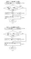
ここで、図4を参照して、第3図柄表示装置81の表示内容について説明する。図4は、第3図柄表示装置81の表示画面を説明するための図面であり、図4(a)は、表示画面の領域区分設定と有効ライン設定とを模式的に示した図であり、図4(b)は、実際の表示画面を例示した図である。
Here, with reference to FIG. 4, the display content of the 3rd symbol display apparatus 81 is demonstrated. FIG. 4 is a diagram for explaining a display screen of the third symbol display device 81, and FIG. 4 (a) is a diagram schematically showing area division setting and effective line setting of the display screen, FIG. 4B is a diagram illustrating an actual display screen.
第3図柄は、「0」から「9」の数字で構成された10種類の主図柄により構成されている。各主図柄は、木箱よりなる後方図柄の上に「0」から「9」の数字を付して構成されている。
The third symbol is composed of ten types of main symbols composed of numbers from “0” to “9”. Each main symbol is configured by attaching numbers “0” to “9” on a rear symbol made of a wooden box.
また、本実施形態のパチンコ機10においては、後述する主制御装置110(図8参照)により行われる特別図柄の抽選結果が大当たりであった場合に、同一の主図柄が揃う変動表示が行われ、その変動表示が終わった後に大当たりが発生するよう構成されている。一方、特別図柄の抽選結果が外れであった場合は、同一の主図柄が揃わない変動表示が行われる。
Further, in the pachinko machine 10 of the present embodiment, when the lottery result of the special symbol performed by the main controller 110 (see FIG. 8) described later is a big hit, the variable display in which the same main symbols are aligned is performed. The jackpot is configured to occur after the change display is finished. On the other hand, when the lottery result of the special symbol is out of place, the variable display in which the same main symbols are not arranged is performed.
例えば、特別図柄の抽選結果が「大当たりA」であれば、奇数番号である「1,3,5,7,9」が付加された主図柄が揃う変動表示が行われる。また、「大当たりB」であれば、偶数番号である「0,2、4,6,8」が付加された主図柄が揃う変動表示が行われる。一方、特別図柄の抽選結果が外れであれば、同一番号の主図柄が揃わない変動表示が行われる。
For example, if the lottery result of the special symbol is “Large A”, a variable display is performed in which the main symbols to which “1, 3, 5, 7, 9”, which is an odd number, are added are aligned. Further, if “big hit B”, the variable display is performed in which the main symbols to which the even numbers “0, 2, 4, 6, 8” are added are aligned. On the other hand, if the lottery result of the special symbol is off, the variable display in which the main symbols of the same number are not aligned is performed.
図4(a)に示すように、第3図柄表示装置81の表示画面は、大きくは上下に2分割され、上側の3/4が第3図柄を変動表示する主表示領域Dm、それ以外の下側の1/4が保留球数などを表示する副表示領域Dsとなっている。
As shown in FIG. 4 (a), the display screen of the 3rd symbol display device 81 is roughly divided into two vertically and the upper 3/4 is the main display area Dm for displaying the 3rd symbol variably, The lower ¼ is a sub display area Ds for displaying the number of reserved balls and the like.
主表示領域Dmは、左・中・右の3つの表示領域Dm1〜Dm3に区分けされており、その3つの表示領域Dm1〜Dm3に、それぞれ3つの図柄列Z1,Z2,Z3が表示される。各図柄列Z1〜Z3には、上述した第3図柄が規定の順序で表示される。即ち、各図柄列Z1〜Z3には、数字の昇順または降順に主図柄が配列され、各図柄列Z1〜Z3毎に周期性をもって上から下へとスクロールして変動表示が行われる。特に、左図柄列Z1においては主図柄の数字が降順に現れるように配列され、中図柄列Z2及び右図柄列Z3においては主図柄の数字が昇順に現れるように配列されている。
The main display area Dm is divided into three display areas Dm1 to Dm3 of left, middle, and right, and three symbol rows Z1, Z2, and Z3 are displayed in the three display areas Dm1 to Dm3, respectively. In each symbol row Z1 to Z3, the above-described third symbols are displayed in a prescribed order. That is, in each symbol row Z1 to Z3, main symbols are arranged in ascending order or descending order of numbers, and each symbol row Z1 to Z3 is scrolled from the top to the bottom with periodicity to perform variable display. In particular, the left symbol row Z1 is arranged so that the numbers of the main symbols appear in descending order, and the middle symbol row Z2 and the right symbol row Z3 are arranged so that the numbers of the main symbols appear in ascending order.
また、主表示領域Dmには、各図柄列Z1〜Z3毎に上・中・下の3段に第3図柄が表示される。この主表示領域Dmの中段部が有効ラインL1として設定されており、毎回の遊技に際して、左図柄列Z1→右図柄列Z3→中図柄列Z2の順に、有効ラインL1上に第3図柄が停止表示される。その第3図柄の停止時に有効ラインL1上に大当たり図柄の組合せ(本実施形態では、同一の主図柄の組合せ)で揃えば大当たりとして大当たり動画が表示される。
In the main display area Dm, the third symbols are displayed in the upper, middle, and lower three rows for each symbol row Z1 to Z3. The middle part of the main display area Dm is set as the active line L1, and in each game, the third symbol stops on the active line L1 in the order of the left symbol row Z1, the right symbol row Z3, and the middle symbol row Z2. Is displayed. If the combination of jackpot symbols (the same main symbol combination in this embodiment) is arranged on the effective line L1 when the third symbol is stopped, a jackpot moving image is displayed as a jackpot.
一方、副表示領域Dsは、主表示領域Dmよりも下方に横長に設けられている。このうち、副表示領域Dsは、第1入球口64に入球された球のうち変動が未実行である球(保留球)の数である保留球数を表示する領域である。
On the other hand, the sub display area Ds is provided horizontally long below the main display area Dm. Among these, the sub display area Ds is an area for displaying the number of reserved balls, which is the number of spheres that have not been changed (reserved spheres) among the balls that have entered the first entrance 64.
実際の表示画面では、図4(b)に示すように、主表示領域Dmに第3図柄の主図柄が合計3個表示される。
On the actual display screen, as shown in FIG. 4B, a total of three main symbols of the third symbol are displayed in the main display area Dm.
一方、第3図柄表示装置81(第1図柄表示装置37)にて変動表示が行われている間に球が第1入球口64へ入球した場合、その入球回数は最大4回まで保留され、その保留球数は第1図柄表示装置37により示されると共に、副表示領域Dsにおいても示される。副表示領域Dsには、保留球数1球につき1つの保留球数図柄が表示され、その保留球数図柄の表示数に応じて、保留球数が表示される。即ち、副表示領域Ds1に1つの保留球数図柄が表示されている場合は、保留球数が1球であることを示し、4つの保留球数図柄が表示されている場合は、保留球数が4球であることを示す。また、副表示領域Dsに保留球数図柄が表示されていない場合は、保留球数が0球である、即ち、保留球が存在しないことを示す。
On the other hand, when a ball enters the first entrance 64 while the variable display is performed on the 3rd symbol display device 81 (1st symbol display device 37), the number of entrances is up to 4 times. The number of balls held is indicated by the first symbol display device 37 and also in the sub display area Ds. In the sub display area Ds, one reserved ball number symbol is displayed per one reserved ball number, and the number of reserved balls is displayed in accordance with the number of displayed retained ball number symbols. That is, when one reserved ball number symbol is displayed in the sub display area Ds1, it indicates that the number of reserved balls is one, and when four reserved ball number symbols are displayed, the number of reserved balls is Indicates four balls. In addition, when the number of reserved balls is not displayed in the sub display area Ds, it indicates that the number of reserved balls is 0, that is, there is no reserved ball.
なお、本実施形態においては、第1入球口64への入球は、最大4回まで保留されるように構成したが、最大保留球数は4回に限定されるものでなく、3回以下、又は、5回以上の回数(例えば、8回)に設定しても良い。また、副表示領域Dsにおける保留球数図柄の表示に代えて、保留球数を第3図柄表示装置81の一部に数字で、或いは、4つに区画された領域を保留球数分だけ異なる態様(例えば、色や点灯パターン)にして表示するようにしても良い。また、第1図柄表示装置37により保留球数が示されるので、第3図柄表示装置81に保留球数を表示させないものとしてもよい。更に、可変表示装置ユニット80に、保留球数を示す保留ランプを最大保留数分の4つ設け、点灯状態の保留ランプの数に応じて、保留球数を表示するものとしてもよい。
In the present embodiment, the ball entering the first ball inlet 64 is configured to be held up to four times, but the maximum number of balls to be held is not limited to four times, but three times. You may set below or 5 times (for example, 8 times). Further, instead of displaying the reserved ball number symbol in the sub-display area Ds, the reserved ball number is different in a part of the third symbol display device 81, or the four divided areas are different by the number of reserved balls. You may make it display in a mode (for example, a color and a lighting pattern). Further, since the number of reserved balls is indicated by the first symbol display device 37, the number of reserved balls may not be displayed on the third symbol display device 81. Furthermore, the variable display device unit 80 may be provided with four hold lamps indicating the number of held balls, corresponding to the maximum number of held balls, and the number of held balls may be displayed according to the number of held lamps that are lit.
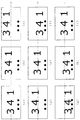
次に、図5を参照して、主表示領域Dmで表示される第3図柄の停止時に行われる揺れ変動についての詳細な変動の流れについて示した図である。第3図柄が変動表示(動的表示)される場合に、停止表示される前に第3図柄が仮停止していることを示す揺らして変動表示させる揺れ変動について示した図である。予め定められた変動態様が表示された後に、後述する主制御装置110から出力される確定コマンドを受信するまで間に仮停止していることを示す揺れ変動が表示される。
Next, with reference to FIG. 5, it is the figure shown about the flow of the detailed fluctuation | variation about the fluctuation fluctuation | variation performed at the time of the stop of the 3rd symbol displayed on the main display area Dm. When the 3rd symbol is displayed in a variable manner (dynamic display), it is a diagram showing the swinging fluctuation that is displayed in a swinging manner to indicate that the 3rd symbol is temporarily stopped before being stopped and displayed. After a predetermined variation mode is displayed, a fluctuation variation indicating that the vehicle is temporarily stopped until a confirmation command output from the main control device 110 described later is received is displayed.
図5(a)〜(i)は、後述する表示制御装置114のワークRAM233のデータテーブル格納エリア233aに記憶されている変動表示データテーブルに設定されている20ms毎の表示画像をそれぞれ示している。図5(a),(e),(i)は、特別図柄が主表示領域Dmの中央位置に表示される揺れセンターを示している。また、図5(b),(d)は、第3図柄が主表示領域Dmの中央位置L1から揺れ変動の最上昇位置までの中間位置に表示された揺れ上昇中間を示している。図5(c)は揺れ変動において第3図柄が最も上昇して表示される最上昇位置に表示された揺れ上昇を示している。図5(f),(h)は、主表示領域Dmの中央位置L1と揺れ変動において最も下降して表示される最下降位置との中間位置に特別図柄が表示された揺れ下降中間を示している。図5(g)は、揺れ変動において第3図柄が最も下降して表示される最下降位置に表示された揺れ下降を示す図である。
FIGS. 5A to 5I respectively show display images every 20 ms set in the variable display data table stored in the data table storage area 233a of the work RAM 233 of the display control device 114 described later. . FIGS. 5A, 5E, and 5I show the shaking center where the special symbol is displayed at the center position of the main display area Dm. 5 (b) and 5 (d) show the middle of the sway rise in which the third symbol is displayed at the middle position from the center position L1 of the main display area Dm to the highest rise position of the sway fluctuation. FIG.5 (c) has shown the rock | fluctuation raise displayed on the highest raise position where the 3rd symbol raises most and is displayed in fluctuation | variation of a fluctuation | variation. FIGS. 5 (f) and 5 (h) show a swing-down middle where a special symbol is displayed at an intermediate position between the center position L1 of the main display area Dm and the lowest-falling position displayed in the swing fluctuation. Yes. FIG. 5 (g) is a diagram showing the swing descent displayed at the lowest position where the third symbol is displayed with the lowest drop in the fluctuation of the swing.
図5(a)は、変動表示データテーブルのアドレス02E7Hで指定される描画内容(表示内容)に対応した図である。同様に図5(b)は、アドレス02E8H、図5(c)は、アドレス02E9H、図5(d)は、アドレス02EAH、図5(e)は、アドレス02EBH、図5(f)は、アドレス02ECH、図5(g)は、アドレス02EDH、図5(h)は、アドレス02EEH、図5(i)は、アドレス02EFHにそれぞれ対応した描画内容を示した図である。詳細は後述するが図5(a)〜(i)までの描画内容が20msずつそれぞれ順に表示されることで、第3図柄が揺れて変動表示される揺れ変動の1周期が表示される構成となっている。
FIG. 5A is a diagram corresponding to the drawing content (display content) specified by the address 02E7H of the variable display data table. Similarly, FIG. 5B shows an address 02E8H, FIG. 5C shows an address 02E9H, FIG. 5D shows an address 02EAH, FIG. 5E shows an address 02EBH, and FIG. 5F shows an address. FIG. 5E shows the contents of drawing corresponding to the address 02EDH, FIG. 5H shows the drawing contents corresponding to the address 02EEH, and FIG. 5I shows the drawing contents corresponding to the address 02EFH. Although the details will be described later, the drawing contents of FIGS. 5A to 5I are displayed in order of 20 ms each, so that one cycle of the fluctuation fluctuation in which the third symbol is changed and displayed is displayed. It has become.
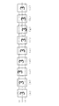
また、図6は、第3図柄の1つの揺れを詳細に示した図である。図6(a)〜図6(i)は、図5(a)〜(i)と同様に変動表示データテーブルで設定される揺れ変動における特別図柄の揺れを順に示した図である。図6に示すように、主表示領域Dmの中央位置L1を中心に、上下に移動表示されて上下に揺れて変動表示される。
FIG. 6 is a diagram showing in detail one shaking of the third symbol. 6 (a) to 6 (i) are diagrams sequentially illustrating the shaking of the special symbol in the shaking fluctuation set in the fluctuation display data table as in FIGS. 5 (a) to (i). As shown in FIG. 6, the display is moved up and down around the center position L1 of the main display area Dm, and the display is fluctuated up and down.
主制御装置110では、第1入球口64へ球が入球(始動入賞)すると、それをトリガとして、特別図柄の抽選が行われ、その後、第1図柄表示装置37において特別図柄(第1図柄)の変動表示が実行される。更に、主制御装置110から音声ランプ制御装置113へ変動パターンコマンドおよび停止種別コマンドが送信され、その結果、第3図柄表示装置81では、第1図柄表示装置37の変動表示に応じて第3図柄の変動表示が行われる。
In the main controller 110, when a ball enters the first entrance 64 (start winning prize), a special symbol lottery is performed using the ball as a trigger, and then a special symbol (first symbol) is displayed on the first symbol display device 37. Variation display of symbols is executed. Further, the variation pattern command and the stop type command are transmitted from the main control device 110 to the sound lamp control device 113. As a result, the third symbol display device 81 causes the third symbol in accordance with the variation display of the first symbol display device 37. Is displayed.
第3図柄表示装置81において第3図柄の変動表示が行われる場合には、まず、第3図柄の高速変動表示が開始され、その後、予め定められた時間(例えば、10秒〜60秒など)が経過すると、第3図柄の中速変動表示へ切り替わり、更に、第3図柄の低速変動表示へ切り替わる。ここで、特別図柄の抽選結果が大当たりである場合には、同一番号の主図柄(第3図柄)が揃う仮停止表示が行われて揺れ変動が実行された後に、主制御装置110から出力される大当たり確定コマンドを受信したことに基づいて変動演出が終了し、続けて、大当たり演出が開始される。一方、特別図柄の抽選結果が外れである場合には、同一番号の主図柄(第3図柄)が揃わない仮停止表示が行われて、仮停止していることを示す揺れ変動表示が実行されて、主制御装置110から出力される外れ確定コマンドを受信したことに基づいて変動演出が終了し、保留されている始動入賞があれば、次の特別図柄の抽選が行われると共に、次の変動演出が開始される。
When the 3rd symbol variation display is performed on the 3rd symbol display device 81, first, the 3rd symbol's high-speed variation display is started, and then a predetermined time (for example, 10 seconds to 60 seconds). When elapses, the display switches to the medium symbol variation display of the third symbol, and further switches to the low symbol variation display of the third symbol. Here, when the lottery result of the special symbol is a big hit, the temporary stop display in which the main symbols of the same number (the third symbol) are aligned is performed and the fluctuation fluctuation is executed, and then output from the main controller 110. On the basis of receiving the jackpot confirmation command, the variation effect ends, and then the jackpot effect is started. On the other hand, when the lottery result of the special symbol is out of place, the temporary stop display in which the main symbols of the same number (the third symbol) are not aligned is performed, and the fluctuation variation display indicating that the temporary stop is performed is executed. Then, if the variation effect ends based on the reception of the deviation confirmation command output from the main controller 110 and there is a pending start prize, the next special symbol will be drawn and the next variation will be performed. Production begins.
図7を参照して、第3図柄の変動パターンの一例として抽選結果が外れの場合に表示される外れ変動パターンの表示態様の流れについて説明する。図7は、第3図柄を変動表示させる外れ変動パターンの流れを示すタイミングチャートである。詳細については、後述するが、主制御装置110が出力する変動パターンコマンドを音声ランプ制御装置113が受信すると、表示制御装置114に対して表示用変動パターンコマンドが出力され、表示制御装置114のMPU231により受信した表示用変動パターンコマンドが示す表示内容が格納された表示用データテーブルが設定され、第3図柄表示装置81に第3図柄の変動表示が開始される。図7に示すように、第3図柄の変動表示が開始されると所定時間後(予め選択された変動パターンに設定されている時間)Z1tに第3図柄のうち、左図柄が主図柄表示領域Dmの中央位置L1に仮停止表示されて揺れ変動表示される。次に、Z3tにおいて右図柄が主図柄表示領域Dmの中央位置L1に仮停止表示されて揺れ変動表示される。その後、Z2tにおいて中図柄が主図柄表示領域Dmの中央位置L1に仮停止表示されて、揺れ変動表示される。その後、第3図柄(左図柄、右図柄、中図柄)は、揺れ変動表示が繰り返し行われる。揺れ変動が図5(a)〜(i)に示すように一連の流れで実行されて、図5(h)に示すように揺れ下降中間の表示を経て揺れセンターで表示された後、変動時間の終了までの200msの間、揺れセンターの表示で揺れ変動が停止表示され、表示用外れ確定コマンドを変動時間終了時に受信した場合には、そのまま確定停止表示の処理が実行される。ここで、確定停止表示の処理につていは、詳細を後述するが、揺れ変動で表示されている第3図柄と同一の図柄が揺れセンター(図5(i))と同一に主表示領域Dmの中心位置L1に第3図柄が表示される確定表示図柄と切替えて表示される。一方、表示用外れ確定コマンドを受信しない場合には、再び揺れ変動が再開され、表示用外れ確定コマンドを受信すると揺れ変動が確定停止表示される。この場合も、上述したのと同様に、揺れセンター(図5(i))で表示されるのと同様の図柄に切り替えて第3図柄の確定図柄として停止表示される。
With reference to FIG. 7, the flow of the display mode of the deviation variation pattern displayed when the lottery result is deviation will be described as an example of the variation pattern of the third symbol. FIG. 7 is a timing chart showing the flow of a deviation variation pattern in which the third symbol is variably displayed. Although details will be described later, when the sound lamp control device 113 receives the variation pattern command output from the main control device 110, the display variation pattern command is output to the display control device 114, and the MPU 231 of the display control device 114 is output. The display data table storing the display content indicated by the display variation pattern command received by the above is set, and the variation display of the third symbol is started on the third symbol display device 81. As shown in FIG. 7, when the variation display of the third symbol is started, the left symbol of the third symbol is the main symbol display area after a predetermined time (the time set in the variation pattern selected in advance) Z1t. A temporary stop display is displayed at the center position L1 of Dm, and the fluctuation is displayed. Next, at Z3t, the right symbol is temporarily stopped at the center position L1 of the main symbol display area Dm, and the fluctuation is displayed. Thereafter, at Z2t, the middle symbol is temporarily stopped and displayed at the center position L1 of the main symbol display area Dm, and the fluctuation is displayed. After that, for the third symbol (left symbol, right symbol, middle symbol), the fluctuation variation display is repeatedly performed. As shown in FIGS. 5 (a) to 5 (i), the fluctuation of the fluctuation is executed in a series of steps, and is displayed at the fluctuation center through the middle of the movement as shown in FIG. 5 (h). During the 200 ms until the end of, the fluctuation fluctuation is stopped and displayed on the display of the fluctuation center, and when the display detachment confirmation command is received at the end of the fluctuation time, the confirmation stop display process is executed as it is. Here, the details of the fixed stop display process will be described later. However, the same symbol as the third symbol displayed by the fluctuation fluctuation is the same as the fluctuation center (FIG. 5 (i)), and the main display area Dm. Is switched to a fixed display symbol in which the third symbol is displayed at the center position L1. On the other hand, if the display deviation confirmation command is not received, the shaking fluctuation is resumed, and when the display deviation confirmation command is received, the fluctuation fluctuation is confirmed and stopped. In this case as well, as described above, the symbol is switched to the same symbol as that displayed at the shaking center (FIG. 5 (i)) and stopped and displayed as the fixed symbol of the third symbol.
正常な状態であれば、変動時間の終了時点で、表示用外れ確定コマンドを受信するので、揺れ変動が実行され、一連の揺れセンターまでの揺れ変動がされた後に、200msの間、揺れセンター(図5(i))の表示がされている状態で、その揺れセンター(図5(i))と同様の第3図柄を確定図柄として切り替えて表示することで停止表示される。これにより、揺れ変動をしている状態から図5(a)〜(i)に示すように1周期の揺れ変動が終了したタイミングである揺れセンター(図5(i))に示すように第3図柄を主図柄表示領域Dmの中央位置L1で自然な揺れ変動で変動表示させた状態から、確定表示で切り替えられる揺れセンター(図5(i))で表示されている図柄の同様の第3図柄の表示態様で切替えて表示することで確定停止させることができる。よって、第3図柄を一連(1周期)の揺れ変動である揺れ下降中間の表示を経てから揺れセンターの表示がされた状態から同じ第3図柄の表示態様で切り替えて確定停止表示させることができ、揺れ変動の最後と確定表示させる図柄とを一致させて、違和感なく停止させることができる。また、表示制御装置114での計時と、主制御装置110の計時にズレが生じて、表示制御装置114が計時する変動時間の終了時間よりも早く表示用外れ確定コマンドまたは表示用大当たり確定コマンドを受信した場合にも、200msの範囲であれば、通常通りきれいに一定の表示で第3図柄を停止表示させることができる。
In the normal state, since the display deviation confirmation command is received at the end of the fluctuation time, the fluctuation fluctuation is executed, and after the fluctuation fluctuation to a series of fluctuation centers is performed, the fluctuation center ( In the state shown in FIG. 5 (i), the display is stopped by switching the third symbol similar to that of the shaking center (FIG. 5 (i)) as the confirmed symbol. As a result, as shown in FIG. 5 (a) to (i), the third fluctuation center (FIG. 5 (i)) is the timing at which one cycle of fluctuation fluctuation is completed. A third symbol similar to the symbol displayed at the shaking center (Fig. 5 (i)) that can be switched by the fixed display from the state in which the symbol is variably displayed at the central position L1 of the main symbol display area Dm. It is possible to confirm and stop by switching and displaying in the display mode. Therefore, the 3rd symbol can be switched to the same 3rd symbol display mode from the state in which the center of shaking is displayed after passing through a series of fluctuations (one period) of fluctuation fluctuation, and can be confirmed and stopped. Thus, it is possible to make the end of the fluctuation of fluctuation coincide with the symbol to be confirmed and stop without a sense of discomfort. In addition, a time difference between the time measured by the display control device 114 and the time measured by the main control device 110 occurs, and a display detachment confirmation command or a display jackpot confirmation command is issued earlier than the end time of the variable time counted by the display control device 114. Even when received, within the range of 200 ms, the third symbol can be stopped and displayed with a constant display as usual.
なお、第3図柄表示装置81で表示される第3図柄は、第1図柄表示装置37で表示される第1図柄と同期して変動表示される図柄であり、第1図柄が変動停止されるタイミングに合わせて、第3図柄も主制御装置110から出力される外れ確定コマンドまたは大当たり確定コマンドに基づいて変動停止される。第1図柄は主制御装置110により変動表示の制御が直接されるが、第3図柄は、主制御装置110から出力される各種制御信号に基づいて表示制御装置114により制御されるものである。主制御装置110と音声ランプ制御装置113(表示制御装置114)とは、主制御装置110から音声ランプ制御装置113に対してコマンドを送信する一方向通信の構成となっている。そのため、主制御装置110は、第3図柄表示装置81で第3図柄がどのような状態で表示されているか(例えば、揺れ変動中の揺れセンターの表示であるか、揺れ下降の表示であるか等)を判別することはできない構成であり、主制御装置110のMPU201が管理する計時時間により特別図柄の変動時間の終了時間となると、一方的に第3図柄の停止を指示する外れ確定コマンドまたは大当たり確定コマンドを音声ランプ制御装置113に対して出力する構成である。
The 3rd symbol displayed on the 3rd symbol display device 81 is a symbol that is variably displayed in synchronization with the 1st symbol displayed on the 1st symbol display device 37, and the 1st symbol is variably stopped. In accordance with the timing, the third symbol is also variably stopped based on the come-off confirmation command or jackpot confirmation command output from the main controller 110. The first symbol is directly controlled by the main controller 110, while the third symbol is controlled by the display controller 114 based on various control signals output from the main controller 110. The main control device 110 and the sound lamp control device 113 (display control device 114) have a one-way communication configuration in which a command is transmitted from the main control device 110 to the sound lamp control device 113. For this reason, the main controller 110 displays in what state the 3rd symbol is displayed on the 3rd symbol display device 81 (for example, whether it is a display of a shaking center during fluctuation fluctuation, or a display of a descent of shaking) Etc.), and when the end time of the special symbol variation time is reached by the time measured by the MPU 201 of the main controller 110, a detachment confirmation command that unidirectionally instructs the stop of the third symbol or The jackpot confirmation command is output to the sound lamp control device 113.
そして、音声ランプ制御装置113は主制御装置110から外れ確定コマンドまたは大当たり確定コマンドを受信すると、表示制御装置114に対して一方的に第3図柄の停止を指示する表示用外れ確定コマンドまたは表示用大当たり確定コマンドを出力する。よって、第3図柄が揺れ変動されている場合に、揺れ下降の表示で表示用外れ確定コマンドまたは表示用大当たり確定コマンドを受信した場合には、揺れ下降中間を経ずに、揺れセンターの表示で停止表示されて確定される。そのような場合には、揺れ下降中間の表示を経ずに突然、揺れセンターと同一の表示がされるので、図柄の停止表示が不安定で見にくいものとなってしまう。
When the sound lamp control device 113 receives the detachment confirmation command or jackpot confirmation command from the main control device 110, the display detachment confirmation command or display unidirectionally instructs the display control device 114 to stop the third symbol. The jackpot confirmation command is output. Therefore, when the 3rd pattern is fluctuating, and if a display out-of-display confirmation command or display jackpot confirmation command is received on the display of the swing down, the display of the center of swing is displayed without going through the middle of the swing down. The display is stopped and confirmed. In such a case, the same display as that of the center of the swing is suddenly displayed without passing the display of the middle of the swinging down, so that the stop display of the symbol becomes unstable and difficult to see.
しかしながら、本実施形態では、変動時間が終了するまえの200ms前までに、揺れ変動が揺れセンター(図5(i))まで一連の流れで表示された後、その揺れセンターの表示で200ms表示が維持(停止表示)されるように構成した。このように構成することで、変動時間終了時に正常であれば受信することとなる表示用外れ確定コマンドまたは表示用大当たり確定コマンドを受信した場合に、揺れセンターの位置でそのまま停止表示させることができ、第3図柄の変動を毎回同じ揺れ変動の位置(一連の揺れ変動後の揺れセンターの表示)できれいに停止表示させることができる。よって、揺れ変動が毎回、一連の揺れ変動で表示されて、実際は200msの間、揺れセンターの位置で停止しているものの、遊技者から見れば極めて、短時間の間であるので、一連の揺れ変動後にそのまま停止表示しているように見せることができる。従って、一連の揺れ変動後に毎回、きれいに第3図柄を停止させることができる。その結果、毎回、同じタイミングで第3図柄が停止表示しているように遊技者に見せることができ、遊技者が違和感を持つことなく第3図柄の変動表示を見ることができる。
However, in this embodiment, after the fluctuation time is displayed 200 ms before the end of the fluctuation time, the fluctuation fluctuation is displayed in a series of flow to the fluctuation center (FIG. 5 (i)), and then the display of the fluctuation center is displayed for 200 ms. It was configured to be maintained (stop display). With this configuration, when a display outage confirmation command or display jackpot confirmation command that is received if normal at the end of the fluctuation time is received, it can be stopped and displayed as it is at the position of the shaking center. The variation of the 3rd pattern can be stopped and displayed neatly at the same position of fluctuation fluctuation (display of the fluctuation center after a series of fluctuation fluctuations) every time. Therefore, each time the fluctuation is displayed as a series of fluctuations, and actually stopped at the position of the shaking center for 200 ms, but it is a very short time from the player's point of view. After the change, it can appear as if it is stopped. Therefore, the third symbol can be stopped cleanly every time after a series of fluctuations. As a result, it is possible to show the player as if the third symbol is stopped and displayed at the same timing every time, and the player can see the variation display of the third symbol without feeling uncomfortable.
さらに、第3図柄は、第1図柄が停止されるタイミングで同期して停止表示されるのが好ましく、変動時間中に第3図柄を演出上停止表示させる場合には、仮停止であることを示す揺れ変動させることで遊技者に変動時間中であり、仮停止であることを報知している。ここで、本実施形態の構成のように、変動時間終了間際の200msの間、特別図柄を停止表示させるように構成したが、200msは遊技者から見れば極めて短時間であり、実際は停止表示しているように感じる程度ではなく、しかも、変動時間終了時に表示用外れ確定コマンドまたは表示用大当たり確定コマンドを受信しない場合には、再び、揺れ変動をするように構成してあることから、200msの間、停止表示させても、第1図柄と同期せずに第3図柄のみが停止したようには遊技者には見えず、遊技者を混乱させることを防止できる。また、何かの不具合で表示用外れ確定コマンドまたは表示用大当たり確定コマンドの受信が遅れた場合にも、揺れ変動が再開されるので、第3図柄のみが停止表示してしまう不具合を防止できる。また、揺れ変動の一連の流れは、図5(a)〜(i)までがそれぞれ20msずつ表示される。揺れ変動の一連の流れは、図5(a)が示す揺れセンターの表示がされてから図5(i)が示す揺れセンターの表示が開始されるまでを所要時間とすると、160msとなる。本実施形態における揺れセンターの表示で停止表示する時間を200msとすることで、揺れ変動に必要な所要時間よりも長い時間以上であり、2周期分の揺れ変動よりも短い時間で設定することで、変動時間内の揺れ変動を丁度、一連の揺れ変動が終了した時点の揺れセンターで200msの間、停止表示することが容易に設定できる。また、一時停止させる(200msの間)時間が長くなりすぎて、遊技者に停止しているように見えてしまうのを防止できる。
Furthermore, it is preferable that the 3rd symbol is stopped and displayed in synchronization with the timing when the 1st symbol is stopped. When the 3rd symbol is stopped and displayed for production during the fluctuation time, the 3rd symbol is temporarily stopped. By changing the shaking shown, the player is informed that the time is changing and is a temporary stop. Here, as in the configuration of the present embodiment, the special symbol is stopped and displayed for 200 ms just before the end of the variable time, but 200 ms is extremely short from the player's point of view, and is actually stopped and displayed. In addition, when the display out-of-display confirmation command or the display jackpot confirmation command is not received at the end of the fluctuation time, it is configured so that the fluctuation fluctuates again. Even if the display is stopped for a while, it is not visible to the player as if only the third symbol is stopped without synchronizing with the first symbol, and it is possible to prevent the player from being confused. In addition, even when reception of the display detachment confirmation command or the display jackpot confirmation command is delayed due to some malfunction, the fluctuation of the shake is resumed, so that the problem that only the third symbol is stopped and displayed can be prevented. In addition, as for a series of fluctuations of shaking fluctuation, FIGS. 5A to 5I are displayed for 20 ms each. A series of fluctuations of the fluctuation is 160 ms, assuming that the period from the display of the fluctuation center shown in FIG. 5A to the start of the display of the fluctuation center shown in FIG. By setting the stop display time in the display of the shake center in this embodiment to 200 ms, it is set to a time longer than the time required for the shake fluctuation and shorter than the fluctuation fluctuation for two cycles. In addition, it is possible to easily set the shaking fluctuation within the fluctuation time to be stopped and displayed for 200 ms at the shaking center at the end of the series of shaking fluctuations. In addition, it can be prevented that the player pauses (for 200 ms) for a long time and appears to be stopped by the player.
なお、本実施形態では、変動時間の終了までの200msを揺れセンターの表示で停止表示する構成としたが、変動時間の終了までの残り100msから200msの間、揺れセンターで停止表示することで、変動時間終了後の100msまで停止表示させる構成としてもよい。このように構成することで、表示制御装置114で計時される変動時間と主制御装置110で計時される変動時間にズレが生じて、表示制御装置114で計時する変動時間の終了後に確定コマンドが主制御装置110より出力された場合にも、100msの間であれば、揺れ変動が再開される前であるので、揺れセンターの表示のまま変動停止(確定停止)させることができる。また、その場合にも、一時停止させている時間は200ms以内であるので、遊技者には変動時間終了まえに変動停止したかを判別することが困難であり、第1図柄の変動停止と同期して変動停止したように見せることができる。
In the present embodiment, 200 ms until the end of the fluctuation time is stopped and displayed with the display of the shaking center. However, the remaining 100 ms until the end of the fluctuation time is stopped and displayed at the shaking center for 200 ms. The display may be stopped until 100 ms after the end of the fluctuation time. With this configuration, there is a difference between the variation time measured by the display control device 114 and the variation time measured by the main control device 110, and the confirmation command is issued after the variation time measured by the display control device 114 ends. Even when it is output from the main controller 110, if it is within 100 ms, it is before the fluctuation fluctuation is resumed, so that the fluctuation can be stopped (definite stop) with the display of the fluctuation center. Also in this case, since the pause time is within 200 ms, it is difficult for the player to determine whether or not the fluctuation stop before the end of the fluctuation time. It can appear as if the change stopped.
大当たり演出は、ラウンド演出が行われる期間と、エンディング演出が行われる期間との3つの期間に分けられる。ラウンド演出は、これから開始されるラウンド数を遊技者に報知するための演出である。また、エンディング演出は、特別遊技状態の終了を遊技者に報知すると共に、大当たり終了後に遊技者に付与される遊技価値(普通図柄の時短期間)を遊技者に報知する(時短期間表示を行う)、または、保留されている特別図柄の抽選において抽選結果が大当たりとなることを遊技者に報知する(確定演出表示を行う)ための演出である。尚、エンディング演出において、遊技価値(普通図柄の時短期間)が遊技者に報知されることを「時短期間表示」が行われると称し、保留されている特別図柄の抽選において抽選結果が大当たりとなることが遊技者に報知されることを「確定演出表示」が行われると称す。
The jackpot effect is divided into three periods, a period in which a round effect is performed and a period in which an ending effect is performed. The round effect is an effect for notifying the player of the number of rounds to be started. In addition, the ending effect notifies the player of the end of the special gaming state, and also notifies the player of the game value (ordinary symbol time period) given to the player after the jackpot ends (displays the time period). Or, it is an effect for notifying the player that a lottery result will be a big hit in a special symbol lottery that is on hold (to perform a definite effect display). In the ending effect, the fact that the game value (ordinary symbol short time period) is notified to the player is referred to as “short time period display”, and the lottery result becomes a big hit in the special symbol lottery that is on hold. This is referred to as “confirmed effect display” being performed.
図2に戻って、説明を続ける。第2図柄表示装置83は、球が第2入球口67を通過することに伴って行われる普通図柄の抽選が実行中であるか否かを点灯状態により示すことによって変動表示を行ったり、変動終了後の停止図柄として、その普通図柄の抽選結果に応じた普通図柄(第2図柄)を点灯状態により示すものである。
Returning to FIG. 2, the description will be continued. The second symbol display device 83 performs a variable display by indicating, by a lighting state, whether or not a normal symbol lottery performed as the ball passes through the second entrance 67, As a stop symbol after the end of the change, a normal symbol (second symbol) corresponding to the lottery result of the normal symbol is indicated by a lighting state.
より具体的には、第2図柄表示装置83では、球が第2入球口67を通過する毎に、第2図柄としての「○」の図柄と「×」の図柄とを交互に点灯させる変動表示が行われる。パチンコ機10は、第2図柄表示装置83における変動表示が所定図柄(本実施形態においては「○」の図柄)で停止すると、第1入球口64に付随する電動役物が所定時間だけ作動状態となり(開放される)、その結果、第1入球口64に球が入り易い状態となるように構成されている。球が第2入球口67を通過した通過回数は最大4回まで保留され、その保留球数が上述した第1図柄表示装置37により表示されると共に第2図柄保留ランプ84においても点灯表示される。第2図柄保留ランプ84は、最大保留数分の4つ設けられ、第3図柄表示装置81の下方に左右対称に配設されている。
More specifically, in the second symbol display device 83, every time the ball passes through the second entrance 67, the symbol “◯” and the symbol “x” as the second symbol are alternately lit. Fluctuation display is performed. In the pachinko machine 10, when the variable display on the second symbol display device 83 stops at a predetermined symbol (in this embodiment, a symbol “◯”), the electric accessory attached to the first entrance 64 is activated for a predetermined time. As a result, it is configured such that a ball easily enters the first entrance 64. The number of times the ball has passed through the second entrance 67 is held up to a maximum of 4 times, and the number of held balls is displayed on the first symbol display device 37 and also lit on the second symbol holding lamp 84. The Four second symbol holding lamps 84 are provided corresponding to the maximum number of holdings, and are arranged symmetrically below the third symbol display device 81.
なお、普通図柄(第2図柄)の変動表示は、本実施形態のように、第2図柄表示装置83において複数のランプの点灯と非点灯を切り換えることにより行うものの他、第1図柄表示装置37及び第3図柄表示装置81の一部を使用して行うようにしても良い。同様に、第2図柄保留ランプ84の点灯を第3図柄表示装置81の一部で行うようにしても良い。また、第2入球口67における球の通過は、第1入球口64と同様に、最大保留球数は4回に限定されるものでなく、3回以下、又は、5回以上の回数(例えば、8回)に設定しても良い。また、第1図柄表示装置37により保留球数が示されるので、第2図柄保留ランプ84により点灯表示を行わないものとしても良い。
The normal symbol (second symbol) variable display is performed by switching on and off of a plurality of lamps in the second symbol display device 83 as in the present embodiment, as well as the first symbol display device 37. Alternatively, a part of the third symbol display device 81 may be used. Similarly, the second symbol holding lamp 84 may be turned on by a part of the third symbol display device 81. In addition, the passage of the sphere at the second entrance 67 is not limited to 4 times as in the case of the 1st entrance 64, but is limited to 3 times or less, or 5 times or more. (For example, 8 times) may be set. Further, since the number of reserved balls is indicated by the first symbol display device 37, the second symbol reservation lamp 84 may not perform lighting display.
可変表示装置ユニット80の下方には、球が入球し得る第1入球口64が配設されている。この第1入球口64へ球が入球すると遊技盤13の裏面側に設けられる第1入球口スイッチ(図示せず)がオンとなり、その第1入球口スイッチのオンに起因して主制御装置110で特別図柄の抽選がなされ、その抽選結果に応じた表示が第1図柄表示装置37のLED37aで示される。また、第1入球口64は、球が入球すると5個の球が賞球として払い出される入賞口の1つにもなっている。
Below the variable display device unit 80, a first entrance 64 into which a sphere can enter is disposed. When a ball enters the first entrance 64, a first entrance switch (not shown) provided on the back side of the game board 13 is turned on, and the first entrance switch is turned on. The main controller 110 draws a special symbol, and a display corresponding to the lottery result is indicated by the LED 37 a of the first symbol display device 37. The first entrance 64 is also one of the entrances through which 5 balls are paid out as prize balls when a ball enters.
第1入球口64の下方には可変入賞装置65が配設されており、その略中央部分に横長矩形状の特定入賞口(大開放口)65aが設けられている。パチンコ機10においては、主制御装置110で行われる特別図柄の抽選が大当たりとなると、所定時間(変動時間)が経過した後に、大当たりの停止図柄となるよう第1図柄表示装置37のLED37aを点灯させると共に、その大当たりに対応した第3図柄の停止図柄を第3図柄表示装置81に表示させて、大当たりの発生が示される。その後、通常時より多量の賞球の払い出しが行われる特別遊技状態(5ラウンドの大当たり)に遊技状態が遷移する。この特別遊技状態として、通常時には閉鎖されている特定入賞口65aが、所定時間(例えば、30秒経過するまで、或いは、球が10個入賞するまで)開放される。
A variable winning device 65 is disposed below the first ball opening 64, and a horizontally-long rectangular specific winning port (large opening) 65a is provided at a substantially central portion thereof. In the pachinko machine 10, when the special symbol lottery performed in the main controller 110 is a big win, the LED 37a of the first symbol display device 37 is turned on after a predetermined time (fluctuation time) has elapsed so as to become a big hit stop symbol. In addition, a stop symbol of the third symbol corresponding to the jackpot is displayed on the third symbol display device 81 to indicate the occurrence of the jackpot. Thereafter, the game state transitions to a special game state (a big hit of 5 rounds) in which a larger amount of prize balls are paid out than usual. In this special gaming state, the special winning opening 65a that is normally closed is opened for a predetermined time (for example, until 30 seconds have elapsed or ten balls have been won).
この特定入賞口65aは、所定時間が経過すると閉鎖され、その閉鎖後、再度、その特定入賞口65aが所定時間開放される。この特定入賞口65aの開閉動作は、5回(5ラウンド)繰り返し可能にされている。この開閉動作が行われている状態が、遊技者にとって有利な特別遊技状態の一形態であり、遊技者には、遊技上の価値(遊技価値)の付与として通常時より多量の賞球の払い出しが行われる。
The specific winning opening 65a is closed when a predetermined time elapses, and after the closing, the specific winning opening 65a is opened again for a predetermined time. The opening / closing operation of the specific winning opening 65a can be repeated five times (five rounds). The state in which the opening / closing operation is performed is one form of a special gaming state that is advantageous to the player. Is done.
可変入賞装置65は、具体的には、特定入賞口65aを覆う横長矩形状の開閉板と、その開閉板の下辺を軸として前方側に開閉駆動するための大開放口ソレノイド(図示せず)とを備えている。特定入賞口65aは、通常時は、球が入賞できないか又は入賞し難い閉状態になっている。大当たりの際には大開放口ソレノイドを駆動して開閉板を前面下側に傾倒し、球が特定入賞口65aに入賞しやすい開状態を一時的に形成し、その開状態と通常時の閉状態との状態を交互に繰り返すように作動する。
Specifically, the variable winning device 65 includes a horizontally long rectangular opening / closing plate that covers the specific winning opening 65a, and a large opening solenoid (not shown) for opening and closing forward with the lower side of the opening / closing plate as an axis. And. The special winning opening 65a is normally closed so that the ball cannot win or is difficult to win. In the case of a big hit, the large opening opening solenoid is driven to tilt the opening / closing plate to the lower front side to temporarily form an open state in which the ball is likely to win the specific winning opening 65a. It operates to repeat the state and the state alternately.
なお、上記した形態に特別遊技状態は限定されるものではない。特定入賞口65aとは別に開閉される大開放口を遊技領域に設け、第1図柄表示装置37において大当たりに対応したLED37aが点灯した場合に、特定入賞口65aが所定時間開放され、その特定入賞口65aの開放中に、球が特定入賞口65a内へ入賞することを契機として特定入賞口65aとは別に設けられた大開放口が所定時間、所定回数開放される遊技状態を特別遊技状態として形成するようにしても良い。
Note that the special gaming state is not limited to the above-described form. When the game area is provided with a large opening that is opened and closed separately from the specific winning opening 65a, and the LED 37a corresponding to the jackpot is turned on in the first symbol display device 37, the specific winning opening 65a is opened for a predetermined time, and the specific winning opening A special gaming state is defined as a game state in which a large opening provided separately from the specific winning port 65a is opened for a predetermined time and a predetermined number of times when the ball 65 is opened into the specific winning port 65a. You may make it form.
遊技盤13の下側における左右の隅部には、証紙や識別ラベル等を貼着するための貼着スペースK1,K2が設けられ、貼着スペースK1に貼られた証紙等は、前面枠14の小窓35(図1参照)を通じて視認することができる。
Adhesive spaces K1 and K2 for adhering certificate stamps, identification labels, and the like are provided at the left and right corners on the lower side of the game board 13. It can be visually recognized through the small window 35 (see FIG. 1).
更に、遊技盤13には、アウト口66が設けられている。いずれの入賞口63,64,65aにも入球しなかった球はアウト口66を通って図示しない球排出路へと案内される。遊技盤13には、球の落下方向を適宜分散、調整等するために多数の釘が植設されているとともに、風車等の各種部材(役物)が配設されている。
Further, the game board 13 is provided with an out port 66. A ball that has not entered any of the winning openings 63, 64, 65a is guided through an out port 66 to a ball discharge path (not shown). A number of nails are planted on the game board 13 in order to appropriately disperse and adjust the falling direction of the ball, and various members (instruments) such as a windmill are arranged.
図3に示すように、パチンコ機10の背面側には、制御基板ユニット90,91と、裏パックユニット94とが主に備えられている。制御基板ユニット90は、主基板(主制御装置110)と音声ランプ制御基板(音声ランプ制御装置113)と表示制御基板(表示制御装置114)とが搭載されてユニット化されている。制御基板ユニット91は、払出制御基板(払出制御装置111)と発射制御基板(発射制御装置112)と電源基板(電源装置115)とカードユニット接続基板116とが搭載されてユニット化されている。
As shown in FIG. 3, control board units 90 and 91 and a back pack unit 94 are mainly provided on the back side of the pachinko machine 10. The control board unit 90 is unitized by mounting a main board (main control apparatus 110), an audio lamp control board (audio lamp control apparatus 113), and a display control board (display control apparatus 114). The control board unit 91 is unitized by mounting a payout control board (payout control apparatus 111), a firing control board (launching control apparatus 112), a power supply board (power supply apparatus 115), and a card unit connection board 116.
裏パックユニット94は、保護カバー部を形成する裏パック92と払出ユニット93とがユニット化されている。また、各制御基板には、各制御を司る1チップマイコンとしてのMPU、各種機器との連絡をとるポート、各種抽選の際に用いられる乱数発生器、時間計数や同期を図る場合などに使用されるクロックパルス発生回路等が、必要に応じて搭載されている。
The back pack unit 94 includes a back pack 92 and a dispensing unit 93 that form a protective cover. In addition, each control board is used for MPU as a one-chip microcomputer that controls each control, a port for communicating with various devices, a random number generator used for various lotteries, time counting and synchronization. A clock pulse generation circuit or the like is mounted as necessary.
なお、主制御装置110、音声ランプ制御装置113及び表示制御装置114、払出制御装置111及び発射制御装置112、電源装置115、カードユニット接続基板116は、それぞれ基板ボックス100〜104に収納されている。基板ボックス100〜104は、ボックスベースと該ボックスベースの開口部を覆うボックスカバーとを備えており、そのボックスベースとボックスカバーとが互いに連結されて、各制御装置や各基板が収納される。
The main control device 110, the sound lamp control device 113 and the display control device 114, the payout control device 111 and the firing control device 112, the power supply device 115, and the card unit connection board 116 are housed in the board boxes 100 to 104, respectively. . The board boxes 100 to 104 include a box base and a box cover that covers the opening of the box base. The box base and the box cover are connected to each other, and each control device and each board are accommodated.
また、基板ボックス100(主制御装置110)及び基板ボックス102(払出制御装置111及び発射制御装置112)は、ボックスベースとボックスカバーとを封印ユニット(図示せず)によって開封不能に連結(かしめ構造による連結)している。また、ボックスベースとボックスカバーとの連結部には、ボックスベースとボックスカバーとに亘って封印シール(図示せず)が貼着されている。この封印シールは、脆性な素材で構成されており、基板ボックス100,102を開封するために封印シールを剥がそうとしたり、基板ボックス100,102を無理に開封しようとすると、ボックスベース側とボックスカバー側とに切断される。よって、封印ユニット又は封印シールを確認することで、基板ボックス100,102が開封されたかどうかを知ることができる。
Further, the substrate box 100 (main control device 110) and the substrate box 102 (dispensing control device 111 and launch control device 112) connect the box base and the box cover so that they cannot be opened by a sealing unit (not shown) (caulking structure). Consolidated). In addition, a seal (not shown) is attached to the connecting portion between the box base and the box cover so as to cover the box base and the box cover. This seal seal is made of a brittle material. If the seal is to be peeled off in order to open the substrate boxes 100, 102, or if the substrate boxes 100, 102 are forcibly opened, the box base side and the box cover are removed. Cut to the side. Therefore, it is possible to know whether or not the substrate boxes 100 and 102 have been opened by checking the sealing unit or the sealing seal.
払出ユニット93は、裏パックユニット94の最上部に位置して上方に開口したタンク130と、タンク130の下方に連結され下流側に向けて緩やかに傾斜するタンクレール131と、タンクレール131の下流側に縦向きに連結されるケースレール132と、ケースレール132の最下流部に設けられ、払出モータ216(図6参照)の所定の電気的構成により球の払出を行う払出装置133とを備えている。タンク130には、遊技ホールの島設備から供給される球が逐次補給され、払出装置133により必要個数の球の払い出しが適宜行われる。タンクレール131には、当該タンクレール131に振動を付加するためのバイブレータ134が取り付けられている。
The payout unit 93 includes a tank 130 that is located at the top of the back pack unit 94 and opens upward, a tank rail 131 that is connected to the lower side of the tank 130 and is gently inclined toward the downstream side, and downstream of the tank rail 131. A case rail 132 that is vertically connected to the side, and a payout device 133 that is provided at the most downstream portion of the case rail 132 and that pays out a ball by a predetermined electrical configuration of the payout motor 216 (see FIG. 6). ing. Balls supplied from the island facilities of the game hall are sequentially replenished to the tank 130, and a required number of balls are paid out by the payout device 133 as appropriate. A vibrator 134 for applying vibration to the tank rail 131 is attached to the tank rail 131.
また、払出制御装置111には状態復帰スイッチ120が設けられ、発射制御装置112には可変抵抗器の操作つまみ121が設けられ、電源装置115にはRAM消去スイッチ122が設けられている。状態復帰スイッチ120は、例えば、払出モータ216(図6参照)部の球詰まり等、払出エラーの発生時に球詰まりを解消(正常状態への復帰)するために操作される。操作つまみ121は、発射ソレノイドの発射力を調整するために操作される。RAM消去スイッチ122は、パチンコ機10を初期状態に戻したい場合に電源投入時に操作される。
The payout control device 111 is provided with a state return switch 120, the firing control device 112 is provided with a variable resistor operation knob 121, and the power supply device 115 is provided with a RAM erase switch 122. The state return switch 120 is operated, for example, to eliminate ball clogging (return to a normal state) when a payout error occurs, such as ball clogging in the payout motor 216 (see FIG. 6). The operation knob 121 is operated to adjust the firing force of the firing solenoid. The RAM erase switch 122 is operated when the power is turned on to return the pachinko machine 10 to the initial state.
次に、図8を参照して、本パチンコ機10の電気的構成について説明する。図8は、パチンコ機10の電気的構成を示すブロック図である。
Next, the electrical configuration of the pachinko machine 10 will be described with reference to FIG. FIG. 8 is a block diagram showing an electrical configuration of the pachinko machine 10.
主制御装置110には、演算装置である1チップマイコンとしてのMPU201が搭載されている。MPU201には、該MPU201により実行される各種の制御プログラムや固定値データを記憶したROM202と、そのROM202内に記憶される制御プログラムの実行に際して各種のデータ等を一時的に記憶するためのメモリであるRAM203と、そのほか、割込回路やタイマ回路、データ送受信回路などの各種回路が内蔵されている。なお、払出制御装置111や音声ランプ制御装置113などのサブ制御装置に対して動作を指示するために、主制御装置110から該サブ制御装置へ各種のコマンドがデータ送受信回路によって送信されるが、かかるコマンドは、主制御装置110からサブ制御装置へ一方向にのみ送信される。
The main controller 110 is equipped with an MPU 201 as a one-chip microcomputer that is an arithmetic unit. The MPU 201 includes a ROM 202 that stores various control programs executed by the MPU 201 and fixed value data, and a memory that temporarily stores various data when the control program stored in the ROM 202 is executed. A certain RAM 203 and various other circuits such as an interrupt circuit, a timer circuit, and a data transmission / reception circuit are incorporated. Various commands are transmitted from the main control device 110 to the sub control device by the data transmission / reception circuit in order to instruct the sub control device such as the payout control device 111 and the sound lamp control device 113 to operate. Such a command is transmitted from the main controller 110 to the sub controller only in one direction.
主制御装置110では、特別図柄の抽選、普通図柄の抽選、第1図柄表示装置37における表示の設定、第2図柄表示装置83における表示の設定、および、第3図柄表示装置81における表示の設定といったパチンコ機10の主要な処理を実行する。そして、RAM203には、これらの処理を制御するための各種カウンタが設けられている。ここで、図9を参照して、主制御装置110のRAM203内に設けられるカウンタ等について説明する。これらのカウンタ等は、特別図柄の抽選、普通図柄の抽選、第1図柄表示装置37における表示の設定、第2図柄表示装置83における表示の設定、および、第3図柄表示装置81における表示の設定などを行うために、主制御装置110のMPU201で使用される。
In main controller 110, special symbol lottery, normal symbol lottery, display setting on first symbol display device 37, display setting on second symbol display device 83, and display setting on third symbol display device 81 The main processing of the pachinko machine 10 is executed. The RAM 203 is provided with various counters for controlling these processes. Here, a counter and the like provided in the RAM 203 of the main controller 110 will be described with reference to FIG. These counters, etc., are a special symbol lottery, a normal symbol lottery, a display setting on the first symbol display device 37, a display setting on the second symbol display device 83, and a display setting on the third symbol display device 81. For example, the MPU 201 of the main control device 110 is used.
特別図柄の抽選や、第1図柄表示装置37および第3図柄表示装置81の表示の設定には、特別図柄の抽選に使用する第1当たり乱数カウンタC1と、特別図柄の大当たり種別を選択するために使用する第1当たり種別カウンタC2と、特別図柄における外れの停止種別を選択するために使用する停止種別選択カウンタC3と、第1当たり乱数カウンタC1の初期値設定に使用する第1初期値乱数カウンタCINI1と、変動パターン選択に使用する変動種別カウンタCS1とが用いられる。また、普通図柄の抽選には、第2当たり乱数カウンタC4が用いられ、第2当たり乱数カウンタC4の初期値設定には第2初期値乱数カウンタCINI2が用いられる。これら各カウンタは、更新の都度、前回値に1が加算され、最大値に達した後0に戻るループカウンタとなっている。
In order to select a special symbol lottery and the first symbol random number counter C1 used for the special symbol lottery and the special symbol lottery for setting the display of the first symbol display device 37 and the third symbol display device 81 The first per-type counter C2 used for the selection, the stop-type selection counter C3 used for selecting the out-of-service stop type in the special symbol, and the first initial value random number used for setting the initial value of the first per-random number counter C1 A counter CINI1 and a variation type counter CS1 used for variation pattern selection are used. In addition, the second random number counter C4 is used for lottery of normal symbols, and the second initial random number counter CINI2 is used for setting the initial value of the second random number counter C4. Each of these counters is a loop counter that adds 1 to the previous value every time it is updated and returns to 0 after reaching the maximum value.
各カウンタは、例えば、タイマ割込処理(図15参照)の実行間隔である2ミリ秒間隔で更新され、また、一部のカウンタは、メイン処理(図23参照)の中で不定期に更新されて、その更新値がRAM203の所定領域に設定されたカウンタ用バッファに適宜格納される。RAM203には、1つの実行エリアと4つの保留エリア(保留第1〜第4エリア)とからなる特別図柄保留球格納エリア203aが設けられており、これらの各エリアには、第1入球口64への入球タイミングに合わせて、第1当たり乱数カウンタC1、第1当たり種別カウンタC2及び停止種別選択カウンタC3の各値がそれぞれ格納される。また、RAM203には、1つの実行エリアと4つの保留エリア(保留第1〜第4エリア)とからなる普通図柄保留球格納エリア203bが設けられており、これらの各エリアには、球が左右何れかの第2入球口(スルーゲート)67を通過したタイミングに合わせて、第2当たり乱数カウンタC4の値が格納される。
Each counter is updated, for example, at an interval of 2 milliseconds, which is the execution interval of the timer interrupt process (see FIG. 15), and some counters are updated irregularly in the main process (see FIG. 23). Then, the updated value is appropriately stored in a counter buffer set in a predetermined area of the RAM 203. The RAM 203 is provided with a special symbol reservation ball storage area 203a including one execution area and four reservation areas (holding first to fourth areas), and each of these areas has a first entrance slot. Each value of the first hit random number counter C1, the first hit type counter C2, and the stop type selection counter C3 is stored in accordance with the timing of entering the ball 64. In addition, the RAM 203 is provided with a normal symbol holding ball storage area 203b composed of one execution area and four holding areas (holding first to fourth areas). The value of the second random number counter C4 is stored in accordance with the timing of passing through any of the second entrances (through gates) 67.
各カウンタについて詳しく説明する。第1当たり乱数カウンタC1は、所定の範囲(例えば、0〜299)内で順に1ずつ加算され、最大値(例えば、0〜299の値を取り得るカウンタの場合は299)に達した後0に戻る構成となっている。特に、第1当たり乱数カウンタC1が1周した場合、その時点の第1初期値乱数カウンタCINI1の値が当該第1当たり乱数カウンタC1の初期値として読み込まれる。
Each counter will be described in detail. The first per-random number counter C1 is incremented by 1 within a predetermined range (for example, 0 to 299) and reaches 0 after reaching the maximum value (for example, 299 for a counter that can take a value of 0 to 299). It is the composition which returns to. In particular, when the first random number counter C1 makes one round, the value of the first initial value random number counter CINI1 at that time is read as the initial value of the first random number counter C1.
また、第1初期値乱数カウンタCINI1は、第1当たり乱数カウンタC1と同一範囲で更新されるループカウンタとして構成される。即ち、例えば、第1当たり乱数カウンタC1が0〜299の値を取り得るループカウンタである場合には、第1初期値乱数カウンタCINI1もまた、0〜299の範囲のループカウンタである。この第1初期値乱数カウンタCINI1は、タイマ割込処理(図15参照)の実行毎に1回更新されると共に、メイン処理(図23参照)の残余時間内で繰り返し更新される。
The first initial value random number counter CINI1 is configured as a loop counter that is updated in the same range as the first random number counter C1. That is, for example, when the first random number counter C1 is a loop counter that can take a value of 0 to 299, the first initial value random number counter CINI1 is also a loop counter in the range of 0 to 299. The first initial value random number counter CINI1 is updated once every execution of the timer interrupt process (see FIG. 15) and is repeatedly updated within the remaining time of the main process (see FIG. 23).
第1当たり乱数カウンタC1の値は、例えば定期的に(本実施形態ではタイマ割込処理毎に1回)更新され、球が第1入球口64に入賞したタイミングでRAM203の特別図柄保留球格納エリア203aに格納される。そして、特別図柄の大当たりとなる乱数の値は、主制御装置110のROM202に格納される特別図柄大当たり乱数テーブル(図示せず)によって設定されており、第1当たり乱数カウンタC1の値が、特別図柄大当たり乱数テーブルによって設定された大当たりとなる乱数の値と一致する場合に、特別図柄の大当たりと判定する。また、この特別図柄大当たり乱数テーブルは、特別図柄の低確率時(特別図柄の低確率状態である期間)用と、その低確率時より特別図柄の大当たりとなる確率の高い高確率時(特別図柄の高確率状態である期間)用との2種類に分けられ、それぞれに含まれる大当たりとなる乱数の個数が異なって設定されている。このように、大当たりとなる乱数の個数を異ならせることにより、特別図柄の低確率時と特別図柄の高確率時とで、大当たりとなる確率が変更される。尚、特別図柄の高確率時用の特別図柄大当たり乱数テーブル(図示せず)と、特別図柄の低確率時用の特別図柄大当たり乱数テーブル(図示せず)とは、主制御装置110のROM202内に設けられている。
The value of the first random number counter C1 is updated, for example, periodically (in this embodiment, once for each timer interrupt process), and the special symbol holding ball in the RAM 203 at the timing when the ball wins the first entrance 64. It is stored in the storage area 203a. The random number value that is a special symbol jackpot is set by a special symbol jackpot random number table (not shown) stored in the ROM 202 of the main controller 110, and the value of the first random number counter C1 is the special symbol jackpot random number table C1. When it matches with the value of the random number that becomes the jackpot set by the symbol jackpot random number table, it is determined that the jackpot of the special symbol. In addition, this special symbol jackpot random number table is used for special symbols at low probability (period when the special symbol is in a low probability state), and at high probability (special symbols) that have a higher probability of winning a special symbol than that low probability. The period of a high probability state) is divided into two types, and the number of random numbers that are jackpots included in each is set differently. In this way, by changing the number of random numbers that are jackpots, the probability of jackpots is changed between when the special symbol has a low probability and when the special symbol has a high probability. A special symbol jackpot random number table (not shown) for a special symbol with a high probability and a special symbol jackpot random number table (not shown) for a special symbol with a low probability are stored in the ROM 202 of the main controller 110. Is provided.
第1当たり種別カウンタC2は、特別図柄の大当たりとなった場合に、第1図柄表示装置37の表示態様を決定するものであり、所定の範囲(例えば、0〜99)内で順に1ずつ加算され、最大値(例えば、0〜99の値を取り得るカウンタの場合は99)に達した後0に戻る構成となっている。第1当たり種別カウンタC2の値は、例えば、定期的に(本実施形態ではタイマ割込処理毎に1回)更新され、球が第1入球口64に入賞したタイミングでRAM203の特別図柄保留球格納エリア203aに格納される。
The first hit type counter C2 determines the display mode of the first symbol display device 37 when the special symbol is a big hit, and increments one by one within a predetermined range (for example, 0 to 99). Then, after reaching the maximum value (for example, 99 in the case of a counter that can take a value of 0 to 99), it returns to 0. The value of the first hit type counter C2 is updated, for example, periodically (in this embodiment, once for each timer interrupt process), and the special symbol holding in the RAM 203 is held at the timing when the ball wins the first entrance 64. It is stored in the sphere storage area 203a.
ここで、特別図柄保留球格納エリア203aに格納された第1当たり乱数カウンタC1の値が、特別図柄の大当たりとなる乱数でなければ、即ち、特別図柄の外れとなる乱数であれば、第1図柄表示装置37に表示される停止図柄に対応した表示態様は、特別図柄の外れ時のものとなる。
Here, if the value of the first per-random number counter C1 stored in the special symbol reserved ball storage area 203a is not a random number that is a big hit of the special symbol, that is, if it is a random number that is out of the special symbol, the first The display mode corresponding to the stop symbol displayed on the symbol display device 37 is the one when the special symbol is off.
一方で、特別図柄保留球格納エリア203aに格納された第1当たり乱数カウンタC1の値が、特別図柄の大当たりとなる乱数であれば、第1図柄表示装置37に表示される停止図柄に対応した表示態様は、特別図柄の大当たり時のものとなる。この場合、その大当たり時の具体的な表示態様は、同じ特別図柄保留球格納エリア203aに格納されている第1当たり種別カウンタC2の値が示す表示態様となる。
On the other hand, if the value of the first per-random number counter C1 stored in the special symbol holding ball storage area 203a is a random number that is a big hit of the special symbol, it corresponds to the stop symbol displayed on the first symbol display device 37. The display mode is that of the special symbol jackpot. In this case, the specific display mode at the time of the big hit is the display mode indicated by the value of the first hit type counter C2 stored in the same special symbol reserved ball storage area 203a.
本実施形態のパチンコ機10における第1当たり乱数カウンタC1は、0〜299の範囲の2バイトのループカウンタとして構成されている。この第1当たり乱数カウンタC1において、特別図柄の低確率時に、特別図柄の大当たりとなる乱数値は3個あり、その乱数値である「7,107,282」は、低確率時用の特別図柄大当たり乱数テーブルに格納されている。このように特別図柄の低確率時には、乱数値の総数が300ある中で、大当たりとなる乱数値の総数が3なので、特別図柄の大当たりとなる確率は、「1/100」となる。
The first random number counter C1 in the pachinko machine 10 of the present embodiment is configured as a 2-byte loop counter in the range of 0 to 299. In the first per random number counter C1, there are three random numbers that are big hits of the special symbol when the special symbol has a low probability, and the random value “7, 107, 282” is a special symbol for the low probability. Stored in the jackpot random number table. Thus, when the special symbol has a low probability, the total number of random numbers that are jackpots is 3 among the total number of random number values, and therefore, the probability that the special symbol is jackpot is “1/100”.
一方で、特別図柄の高確率時に、特別図柄の大当たりとなる乱数値は30個あり、その値である「4,11,28,38,45,52,64,78,83,99,106,112,122,134,140,151,168,176,183,197,207,218,222,231,249,256,263,270,285,299」は、高確率時用の特別図柄大当たり乱数テーブルに格納されている。このように特別図柄の高確率時には、乱数値の総数が300ある中で、大当たりとなる乱数値の総数が30なので、特別図柄の大当たりとなる確率は、「1/10」となる。
On the other hand, when there is a high probability of a special symbol, there are 30 random numbers that are jackpots of the special symbol, which are “4, 11, 28, 38, 45, 52, 64, 78, 83, 99, 106, 112, 122, 134, 140, 151, 168, 176, 183, 197, 207, 218, 222, 231, 249, 256, 263, 270, 285, 299 "is a special symbol jackpot random number table for high probability. Stored in In this way, when the special symbol has a high probability, the total number of random numbers that are jackpots is 30 among the total number of random number values, so the probability that the special symbol jackpot is “1/10”.
尚、本実施形態では、低確率時用の特別図柄大当たり乱数テーブルに格納されている大当たりとなる乱数値と、高確率時用の特別図柄大当たり乱数テーブルに格納されている大当たりとなる乱数値とで、重複した値とならないように、それぞれの大当たりとなる乱数値を設定している。ここで、大当たりとなる乱数値としてパチンコ機10の状況にかかわらず常に用いられる値が存在すれば、その乱数値が外部より入力されて、不正に大当たりを引き当てられやすくなるおそれがある。これに対して、本実施形態のように、状況に応じて(即ち、パチンコ機10が特別図柄の高確率状態か、特別図柄の低確率状態かに応じて)、大当たりとなる乱数値を変えることで、特別図柄の大当たりとなる乱数値が予測され難くすることができるので、不正に対する抑制を図ることができる。
In this embodiment, the random number value that is a jackpot stored in the special symbol jackpot random number table for the low probability time, and the random number value that is the jackpot stored in the special symbol jackpot random number table for the high probability time In order to avoid duplicate values, random numbers for each jackpot are set. Here, if there is a value that is always used as a jackpot random value regardless of the situation of the pachinko machine 10, the random value may be input from the outside, and the jackpot may be easily illegally assigned. On the other hand, as in this embodiment, depending on the situation (that is, depending on whether the pachinko machine 10 is in a high probability state of a special symbol or a low probability state of a special symbol), the random number value that is a jackpot is changed. As a result, it is possible to make it difficult to predict a random value that is a big hit of a special symbol, and thus it is possible to suppress fraud.
また、本実施形態のパチンコ機10における第1当たり種別カウンタC2の値は、0〜99の範囲のループカウンタとして構成されている。そして、図10(a)に示すように、この第1当たり種別カウンタC2において、乱数値が「0〜59」であった場合の大当たり種別は、「大当たりA」となる。また、値が「60〜99」であった場合の大当たり種別は、「大当たりB」となる。
Further, the value of the first hit type counter C2 in the pachinko machine 10 of the present embodiment is configured as a loop counter in the range of 0-99. Then, as shown in FIG. 10A, in the first hit type counter C2, the big hit type when the random number value is “0 to 59” is “big hit A”. The jackpot type when the value is “60 to 99” is “jackpot B”.
このように、本実施形態のパチンコ機10は、第1当たり種別カウンタC2が示す乱数の値によって、2種類の当たり種別(大当たりA、大当たりB)が決定されるように構成されている。尚、第1当たり種別カウンタC2の値(乱数値)から、特別図柄の大当たり種別を決定するための乱数値は、特別図柄大当たり種別テーブル(図示せず)により設定されており、このテーブルは、主制御装置110のROM202内に設けられている。
As described above, the pachinko machine 10 of the present embodiment is configured such that two types of hit types (big hit A and big hit B) are determined based on the random number value indicated by the first hit type counter C2. The random value for determining the special symbol jackpot type from the value (random number value) of the first hit type counter C2 is set by a special symbol jackpot type table (not shown). It is provided in the ROM 202 of the main controller 110.
停止種別選択カウンタC3は、例えば0〜99の範囲内で順に1ずつ加算され、最大値(つまり99)に達した後0に戻る構成となっている。本実施形態では、停止種別選択カウンタC3によって、第3図柄表示装置81で表示される外れ時の停止種別が選択され、リーチが発生した後、最終停止図柄がリーチ図柄の前後に1つだけずれて停止する「前後外れリーチ」(例えば98,99)と、同じくリーチ発生した後、最終停止図柄がリーチ図柄の前後以外で停止する「前後外れ以外リーチ」(例えば90〜97の範囲)と、リーチ発生しない「完全外れ」(例えば0〜89の範囲)との3つの停止(演出)パターンが選択される。停止種別選択カウンタC3の値は、例えば定期的に(本実施形態ではタイマ割込処理毎に1回)更新され、球が第1入球口64に入賞したタイミングでRAM203の特別図柄保留球格納エリア203aに格納される。
For example, the stop type selection counter C3 is incremented by 1 within a range of 0 to 99, for example, and reaches a maximum value (that is, 99) and then returns to 0. In the present embodiment, the stop type at the time of release displayed on the third symbol display device 81 is selected by the stop type selection counter C3, and after reach occurs, the final stop symbol is shifted by one before and after the reach symbol. “Rear out of front / rear” (for example, 98, 99), and “reach other than front / rear out of reach” (for example, in the range of 90 to 97) where the final stop symbol stops other than before and after the reach symbol after the occurrence of reach. Three stop (rendering) patterns are selected that are “completely out” (for example, a range of 0 to 89) that does not cause reach. The value of the stop type selection counter C3 is updated, for example, periodically (in this embodiment, once for each timer interrupt process), and the special symbol holding ball is stored in the RAM 203 at the timing when the ball wins the first entrance 64. It is stored in the area 203a.
尚、停止種別選択カウンタC3の値(乱数値)から、特別図柄の停止種別を決定するための乱数値は、停止種別選択テーブル(図示せず)により設定されており、このテーブルは、主制御装置110のROM202内に設けられている。また、本実施形態ではこのテーブルを、特別図柄の高確率時用と、特別図柄の低確率時用とに分けており、テーブルに応じて、外れの停止種別ごとに設定される乱数値の範囲を変えている。これは、パチンコ機10が特別図柄の高確率状態であるか、特別図柄の低確率状態であるか等に応じて、停止種別の選択比率を変更するためである。
The random value for determining the stop type of the special symbol from the value (random number value) of the stop type selection counter C3 is set by a stop type selection table (not shown). It is provided in the ROM 202 of the device 110. In this embodiment, this table is divided into a special symbol for high probability and a special symbol for low probability, and a random value range set for each outage stop type according to the table. Is changing. This is because the selection ratio of the stop type is changed depending on whether the pachinko machine 10 is in a special symbol high probability state or a special symbol low probability state.
例えば、高確率状態では、大当たりが発生し易いため必要以上にリーチ演出が選択されないように、「完全外れ」の停止種別に対応した乱数値の範囲が0〜89と広い高確率時用のテーブルが選択され、「完全外れ」が選択され易くなる。このテーブルは、「前後外れリーチ」が98,99と狭くなると共に「前後外れ以外リーチ」も90〜97と狭くなり、「前後外れリーチ」や「前後外れ以外リーチ」が選択され難くなる。また、低確率状態であれば、第1入球口64への球の入球時間を確保するために「完全外れ」の停止種別に対応した乱数値の範囲が0〜79と狭い低確率時用のテーブルが選択され、「完全外れ」が選択され難くなる。
For example, in a high-probability state, a table for a high-probability time with a wide range of random values from 0 to 89 corresponding to the stop type “completely out” is selected so that a reach effect is not selected more than necessary because a big hit is likely to occur. Is selected, and “completely off” is easily selected. In this table, the “front / rear detachment reach” is narrowed to 98,99, and the “reach other than front / rear detachment” is also narrowed to 90 to 97, making it difficult to select “rearward / rearward detachment reach” and “reach other than front / rear detachment”. In the low probability state, the random value range corresponding to the stop type “completely off” is 0 to 79 and the probability is low so as to secure the time for entering the ball into the first entrance 64. Table is selected, and “completely out” is difficult to select.
この停止種別選択テーブルは、「前後外れ以外リーチ」の停止種別に対応した乱数値の範囲が80〜97と広くなり、「前後外れ以外リーチ」が選択され易くなっている。よって、低確率状態では、演出時間の長いリーチ表示を多く行うことできるので、第1入球口64への球の入球時間を確保でき、第3図柄表示装置81による変動表示が継続して行われ易くなる。尚、後者のテーブルにおいても、「前後外れリーチ」の停止種別に対応した乱数値の範囲は98,99に設定される。
In this stop type selection table, the range of random values corresponding to the stop type of “reach other than front / rear out” is widened to 80 to 97, and “reach other than front / rear out” is easily selected. Therefore, in the low probability state, it is possible to perform a lot of reach display with a long production time, so it is possible to secure the time for entering the ball into the first entrance 64 and the variable display by the third symbol display device 81 is continued. It becomes easy to be done. In the latter table as well, the range of random values corresponding to the stop type of “front / rear out of reach” is set to 98,99.
変動種別カウンタCS1は、例えば0〜198の範囲内で順に1ずつ加算され、最大値(つまり198)に達した後0に戻る構成となっている。変動種別カウンタCS1によって、いわゆるノーマルリーチ、スーパーリーチ等の大まかな表示態様が決定される。表示態様の決定は、具体的には、図柄変動の変動時間の決定である。変動種別カウンタCS1により決定された変動時間に基づいて、音声ランプ制御装置113や表示制御装置114により第3図柄表示装置81で表示される第3図柄のリーチ種別や細かな図柄変動態様が決定される。変動種別カウンタCS1の値は、後述するメイン処理(図23参照)が1回実行される毎に1回更新され、当該メイン処理内の残余時間内でも繰り返し更新される。尚、変動種別カウンタCS1の値(乱数値)から、図柄変動の変動時間を一つ決定する乱数値を格納した変動パターンテーブル(図示せず)は、主制御装置110のROM202内に設けられている。
The variation type counter CS1 is, for example, incremented by 1 within a range of 0 to 198, and returns to 0 after reaching the maximum value (that is, 198). Rough display modes such as so-called normal reach and super reach are determined by the variation type counter CS1. Specifically, the display mode is determined by determining the variation time of the symbol variation. Based on the fluctuation time determined by the fluctuation type counter CS1, the voice lamp control device 113 and the display control device 114 determine the reach type of the third symbol displayed on the third symbol display device 81 and the detailed symbol variation mode. The The value of the variation type counter CS1 is updated once every time a main process (see FIG. 23) described later is executed once, and is repeatedly updated even within the remaining time in the main process. A fluctuation pattern table (not shown) that stores a random value for determining one fluctuation time of symbol fluctuation from the value of the fluctuation type counter CS1 (random number value) is provided in the ROM 202 of the main controller 110. Yes.
変動パターンテーブルには、例えば、外れ用の変動パターンとして、「外れ(長時間用)」、「外れ(短時間用)」、「外れノーマルリーチ」各種、「外れスーパーリーチ」各種、「外れスペシャルリーチ」各種が規定されている。そして、変動パターンテーブルに規定された各種変動パターンから、予測された抽選結果や、予測された停止種別(大当たりの場合には大当たり種別)に応じて変動パターンが選定される。
In the variation pattern table, for example, as a variation pattern for detachment, various types of “out (for long time)”, “out (for short time)”, “out normal reach”, “out super reach”, “out special reach” "Various types are prescribed. Then, a variation pattern is selected from the various variation patterns defined in the variation pattern table according to the predicted lottery result and the predicted stop type (a jackpot type in the case of a jackpot).
第2当たり乱数カウンタC4は、例えば0〜239の範囲内で順に1ずつ加算され、最大値(つまり239)に達した後0に戻るループカウンタとして構成されている。また、第2当たり乱数カウンタC4が1周した場合、その時点の第2初期値乱数カウンタCINI2の値が当該第2当たり乱数カウンタC4の初期値として読み込まれる。第2当たり乱数カウンタC4の値は、本実施形態ではタイマ割込処理毎に、例えば定期的に更新され、球が左右何れかの第2入球口(スルーゲート)67を通過したことが検知された時に取得され、RAM203の普通図柄保留球格納エリア203bに格納される。
The second random number counter C4 is configured as a loop counter that is incremented one by one within a range of, for example, 0 to 239 and returns to 0 after reaching the maximum value (that is, 239). Further, when the second random number counter C4 makes one round, the value of the second initial value random number counter CINI2 at that time is read as the initial value of the second random number counter C4. In this embodiment, the value of the second per-random number counter C4 is periodically updated, for example, every timer interrupt process, and it is detected that the ball has passed through either the left or right second entrance (through gate) 67. And is stored in the normal symbol holding ball storage area 203b of the RAM 203.
そして、普通図柄の当たりとなる乱数の値は、主制御装置のROM202に格納される普通図柄当たり乱数テーブル(図示せず)によって設定されており、第2当たり乱数カウンタC4の値が、普通図柄当たり乱数テーブルによって設定された当たりとなる乱数の値と一致する場合に、普通図柄の当たりと判定する。また、この普通図柄当たり乱数テーブルは、普通図柄の低確率時(普通図柄の通常状態である期間)用と、その低確率時より普通図柄の当たりとなる確率の高い高確率時(普通図柄の時短状態である期間)用との2種類に分けられ、それぞれに含まれる大当たりとなる乱数の個数が異なって設定されている。このように、当たりとなる乱数の個数を異ならせることにより、普通図柄の低確率時と普通図柄の高確率時とで、当たりとなる確率が変更される。
The value of the random number that becomes the normal symbol is set by a random number table (not shown) per normal symbol stored in the ROM 202 of the main controller, and the value of the second random number counter C4 is the normal symbol value. When the winning random number value set by the winning random number table coincides with the winning random number table, it is determined that the normal symbol is hit. In addition, this random number table per normal symbol is used for low probability of a normal symbol (period in which the normal symbol is in a normal state), and at a high probability that the normal symbol is more likely to hit than the low probability (normal symbol of the normal symbol) The number of random numbers that are jackpots included in each is set differently. In this way, by changing the number of random numbers to be won, the probability of winning is changed between the low probability of the normal symbol and the high probability of the normal symbol.
図10(b)に示すように、普通図柄の低確率時に、普通図柄の当たりとなる乱数値は24個あり、その範囲は「5〜28」となっている。これら乱数値は、低確率時用の普通図柄当たり乱数テーブルに格納されている。このように普通図柄の低確率時には、乱数値の総数が240ある中で、大当たりとなる乱数値の総数が24なので、特別図柄の大当たりとなる確率は、「1/10」となる。
As shown in FIG. 10 (b), there are 24 random numbers that are hit by the normal symbol when the normal symbol has a low probability, and the range is “5-28”. These random values are stored in a random table per normal symbol for low probability. Thus, when the probability of a normal symbol is low, the total number of random numbers that are jackpots is 24 among the total number of random number values, and therefore the probability of jacking a special symbol is “1/10”.
パチンコ機10が普通図柄の低確率時である場合に、球が第2入球口67を通過すると、第2当たり乱数カウンタC4の値が取得されると共に、第2図柄表示装置83において普通図柄の変動表示が30秒間実行される。そして、取得された第2当たり乱数カウンタC4の値が「5〜28」の範囲であれば当選と判定されて、第2図柄表示装置83における変動表示が終了した後に、停止図柄(第2図柄)として「○」の図柄が点灯表示されると共に、第1入球口64が「0.2秒間×1回」だけ開放される。尚、本実施形態では、パチンコ機10が普通図柄の低確率時である場合に、普通図柄の当たりとなったら第1入球口64が「0.2秒間×1回」だけ開放されるが、開放時間や回数は任意に設定すれば良い。例えば、「0.5秒間×2回」開放しても良い。
When the pachinko machine 10 has a low probability of a normal symbol, when the ball passes through the second entrance 67, the value of the second random number counter C4 is acquired and the normal symbol is displayed in the second symbol display device 83. Is displayed for 30 seconds. Then, if the value of the acquired second random number counter C4 is in the range of “5 to 28”, it is determined that the winning symbol is selected, and after the variable display on the second symbol display device 83 ends, the stop symbol (second symbol) ), The symbol “◯” is lit and displayed, and the first entrance 64 is opened for “0.2 seconds × 1 time”. In the present embodiment, when the pachinko machine 10 is at a low probability of a normal symbol, the first entrance 64 is opened for “0.2 seconds × one time” when the normal symbol is hit. The opening time and the number of times may be set arbitrarily. For example, “0.5 seconds × 2 times” may be opened.
一方で、普通図柄の高確率時に、普通図柄の大当たりとなる乱数値は200個あり、その範囲は「5〜204」となっている。これらの乱数値は、高確率時用の普通図柄当たり乱数テーブルに格納されている。このように特別図柄の低確率時には、乱数値の総数が240ある中で、大当たりとなる乱数値の総数が200なので、特別図柄の大当たりとなる確率は、「1/1.2」となる。
On the other hand, when there is a high probability of a normal symbol, there are 200 random values that are jackpots of the normal symbol, and the range is “5-204”. These random number values are stored in a random table per symbol for high probability. Thus, when the special symbol has a low probability, the total number of random numbers that are jackpots is 200 among the total number of random number values, and therefore, the probability that the special symbol is jackpot is “1 / 1.2”.
パチンコ機10が普通図柄の高確率時である場合に、球が第2入球口67を通過すると、第2当たり乱数カウンタC4の値が取得されると共に、第2図柄表示装置83において普通図柄の変動表示が3秒間実行される。そして、取得された第2当たり乱数カウンタC4の値が「5〜204」の範囲であれば当選と判定されて、第2図柄表示装置83における変動表示が終了した後に、停止図柄(第2図柄)として「○」の図柄が点灯表示されると共に、第1入球口64が「1秒間×2回」開放される。このように、普通図柄の高確率時には、普通図柄の低確率時と比較して、変動表示の時間が「30秒→3秒」と非常に短くなり、更に、第1入球口64の解放期間が「0.2秒×1回→1秒間×2回」と非常に長くなるので、第1入球口64へ球が入球し易い状態となる。尚、第2当たり乱数カウンタC4の値(乱数値)から、普通図柄の当たりか否かを判定する乱数値を格納したテーブル(図示せず)は、ROM202内に設けられている。尚、本実施形態では、パチンコ機10が普通図柄の高確率時である場合に、普通図柄の当たりとなったら第1入球口64が「1秒間×2回」だけ開放されるが、開放時間や回数は任意に設定すれば良い。例えば、「3秒間×3回」開放しても良い。
When the pachinko machine 10 has a high probability of a normal symbol, when the ball passes the second entrance 67, the value of the second random number counter C4 is acquired and the normal symbol is displayed in the second symbol display device 83. Is displayed for 3 seconds. Then, if the acquired value of the second random number counter C4 is in the range of “5 to 204”, it is determined that the winning symbol is selected, and after the variable display on the second symbol display device 83 ends, the stop symbol (second symbol) ), The symbol “◯” is lit and displayed, and the first entrance 64 is opened “for 1 second × 2 times”. As described above, when the normal symbol has a high probability, the variation display time becomes very short, “30 seconds → 3 seconds”, compared to the normal symbol having a low probability, and further, the first entrance 64 is released. Since the period becomes very long as “0.2 seconds × 1 time → 1 second × 2 times”, it becomes easy for the ball to enter the first entrance 64. Note that a table (not shown) storing random number values for determining whether or not a normal symbol is hit from the value (random number value) of the second hit random number counter C4 is provided in the ROM 202. In the present embodiment, when the pachinko machine 10 has a high probability of a normal symbol, the first entrance 64 is opened only “one second × two times” when the normal symbol is hit. What is necessary is just to set time and frequency | count arbitrarily. For example, “3 seconds × 3 times” may be opened.
第2初期値乱数カウンタCINI2は、第2当たり乱数カウンタC4と同一範囲で更新されるループカウンタとして構成され(値=0〜239)、タイマ割込処理(図15参照)毎に1回更新されると共に、メイン処理(図23参照)の残余時間内で繰り返し更新される。
The second initial value random number counter CINI2 is configured as a loop counter that is updated in the same range as the second random number counter C4 (value = 0 to 239), and is updated once every timer interrupt process (see FIG. 15). And repeatedly updated within the remaining time of the main process (see FIG. 23).
このように、RAM203には種々のカウンタ等が設けられており、主制御装置110では、このカウンタ等の値に応じて大当たり抽選や第1図柄表示装置37および第3図柄表示装置81における表示の設定、第2図柄表示装置83における表示結果の抽選といったパチンコ機10の主要な処理を実行することができる。
As described above, the RAM 203 is provided with various counters and the like, and the main control device 110 performs the big win lottery and the display in the first symbol display device 37 and the third symbol display device 81 according to the value of the counter and the like. The main processing of the pachinko machine 10 such as setting and lottery of the display result on the second symbol display device 83 can be executed.
図8に戻り、説明を続ける。RAM203は、図9に図示した各種カウンタのほか、MPU201の内部レジスタの内容やMPU201により実行される制御プログラムの戻り先番地などが記憶されるスタックエリアと、各種のフラグおよびカウンタ、I/O等の値が記憶される作業エリア(作業領域)とを有している。
Returning to FIG. 8, the description will be continued. In addition to the various counters illustrated in FIG. 9, the RAM 203 stores a stack area for storing the contents of the internal registers of the MPU 201 and the return address of a control program executed by the MPU 201, various flags and counters, I / O, and the like There is a work area (work area) in which the value is stored.
なお、RAM203は、パチンコ機10の電源の遮断後においても電源装置115からバックアップ電圧が供給されてデータを保持(バックアップ)できる構成となっており、RAM203に記憶されるデータは、すべてバックアップされる。
Note that the RAM 203 is configured so that the backup voltage is supplied from the power supply device 115 and the data can be retained (backed up) even after the power of the pachinko machine 10 is shut off, and all data stored in the RAM 203 is backed up. .
停電などの発生により電源が遮断されると、その電源遮断時(停電発生時を含む。以下同様)のスタックポインタや、各レジスタの値がRAM203に記憶される。一方、電源投入時(停電解消による電源投入を含む。以下同様)には、RAM203に記憶される情報に基づいて、パチンコ機10の状態が電源遮断前の状態に復帰される。RAM203への書き込みはメイン処理(図23参照)によって電源遮断時に実行され、RAM203に書き込まれた各値の復帰は電源投入時の立ち上げ処理(図22参照)において実行される。なお、MPU201のNMI端子(ノンマスカブル割込端子)には、停電等の発生による電源遮断時に、停電監視回路252からの停電信号SG1が入力されるように構成されており、その停電信号SG1がMPU201へ入力されると、停電時処理としてのNMI割込処理(図21参照)が即座に実行される。
When the power is shut down due to the occurrence of a power failure or the like, the stack pointer and the value of each register when the power is shut off (including when the power failure occurs, the same applies hereinafter) are stored in the RAM 203. On the other hand, at the time of power-on (including power-on due to power failure cancellation, the same applies hereinafter), the state of the pachinko machine 10 is restored to the state before power-off based on information stored in the RAM 203. Writing to the RAM 203 is executed when the power is shut off by the main process (see FIG. 23), and restoration of each value written in the RAM 203 is executed in a startup process (see FIG. 22) when the power is turned on. Note that the power failure signal SG1 from the power failure monitoring circuit 252 is input to the NMI terminal (non-maskable interrupt terminal) of the MPU 201 when the power is interrupted due to the occurrence of a power failure or the like. Is input immediately, the NMI interrupt process (see FIG. 21) as a power failure process is immediately executed.
また、RAM203は、図8に示すように、特別図柄保留球格納エリア203aと、普通図柄保留球格納エリア203bと、特別図柄保留球数カウンタ203cと、普通図柄保留球数カウンタ203dと、時短中カウンタ203eと、その他記憶エリア203zと、を有している。
As shown in FIG. 8, the RAM 203 has a special symbol reserved ball storage area 203a, a normal symbol reserved ball storage area 203b, a special symbol reserved ball number counter 203c, a normal symbol reserved ball number counter 203d, It has a counter 203e and other storage area 203z.
特別図柄保留球格納エリア203aは、1つの実行エリアと、4つの保留エリア(保留第1エリア〜保留第4エリア)とを有しており、これらの各エリアには、第1当たり乱数カウンタC1、第1当たり種別カウンタC2、及び停止種別選択カウンタC3の各値がそれぞれ格納される。
The special symbol holding ball storage area 203a has one execution area and four holding areas (holding first area to holding fourth area). Each of these areas has a first per-random number counter C1. Each value of the first hit type counter C2 and the stop type selection counter C3 is stored.
より具体的には、球が第1入球口64へ入賞(始動入賞)したタイミングで、各カウンタC1〜C3の各値が取得され、その取得されたデータが、4つの保留エリア(保留第1エリア〜保留第4エリア)の空いているエリアの中で、エリア番号(第1〜第4)の小さいエリアから順番に記憶される。つまり、エリア番号の小さいエリアほど、時間的に古い入賞に対応するデータが記憶され、保留第1エリアには、時間的に最も古い入賞に対応するデータが記憶される。尚、4つの保留エリアの全てにデータが記憶されている場合には、新たに何も記憶されない。
More specifically, each value of each of the counters C1 to C3 is acquired at the timing when the ball wins the first entrance 64 (start winning), and the acquired data is stored in four holding areas (holding first). Among the vacant areas (1 area to reserved 4th area), the areas are stored in order from the area with the smallest area number (1st to 4th). That is, as the area number is smaller, the data corresponding to the winning that is older in time is stored, and the data corresponding to the winning that is older in time is stored in the first reserved area. If data is stored in all four reserved areas, nothing is newly stored.
その後、主制御装置110において、特別図柄の抽選が行われる場合には、特別図柄保留球格納エリア203aの保留第1エリアに記憶されている各カウンタC1〜C3の各値が、実行エリアへシフトされ(移動させられ)、その実行エリアに記憶された各カウンタC1〜C3の各値に基づいて、特別図柄の抽選などの判定が行われる。
Thereafter, when the special control lottery is performed in the main controller 110, the values of the counters C1 to C3 stored in the holding first area of the special symbol holding ball storage area 203a are shifted to the execution area. Then, based on the values of the counters C1 to C3 stored in the execution area, a determination such as lottery of a special symbol is performed.
尚、保留第1エリアから実行エリアへデータをシフトすると、保留第1エリアが空き状態となる。そこで、他の保留エリア(保留第2エリア〜保留第4エリア)に記憶されている入賞のデータを、エリア番号の1小さい保留エリア(保留第1エリア〜保留第3エリア)に詰めるシフト処理が行われる。本実施形態では、特別図柄保留球格納エリア203aにおいて、入賞のデータが記憶されている保留エリア(第2保留エリア〜第4保留エリア)についてのみデータのシフトが行われる。
Note that when the data is shifted from the reserved first area to the execution area, the reserved first area becomes empty. Therefore, a shift process is performed in which winning data stored in other reserved areas (holding second area to holding fourth area) is packed into a holding area having a smaller area number (holding first area to holding third area). Done. In the present embodiment, in the special symbol reserved ball storage area 203a, data is shifted only for the reserved areas (second reserved area to fourth reserved area) where winning data is stored.
普通図柄保留球格納エリア203bは、特別図柄保留球格納エリア203aと同様に、1つの実行エリアと、4つの保留エリア(保留第1エリア〜保留第4エリア)とを有している。これらの各エリアには、第2当たり乱数カウンタC4が格納される。
Similarly to the special symbol reserved ball storage area 203a, the normal symbol reserved ball storage area 203b has one execution area and four reserved areas (holding first area to holding fourth area). In each of these areas, a second random number counter C4 is stored.
より具体的には、球が左右何れかの第2入球口67を通過したタイミングで、カウンタC4の値が取得され、その取得されたデータが、4つの保留エリア(保留第1エリア〜保留第4エリア)の空いているエリアの中で、エリア番号(第1〜第4)の小さいエリアから順番に記憶される。つまり、特別図柄保留球格納エリア203aと同様に、入賞した順序が保持されつつ、入賞に対応するデータが格納される。尚、4つの保留エリアの全てにデータが記憶されている場合には、新たに何も記憶されない。
More specifically, the value of the counter C4 is acquired at the timing when the ball passes through the left or right second entrance 67, and the acquired data is stored in four reservation areas (holding first area to holding). Among the vacant areas of the (fourth area), the areas are stored in order from the area with the smallest area number (first to fourth). That is, as with the special symbol reserved ball storage area 203a, the data corresponding to the winning is stored while the winning order is maintained. If data is stored in all four reserved areas, nothing is newly stored.
その後、主制御装置110において、普通図柄の当たりの抽選が行われる場合には、普通図柄保留球格納エリア203bの保留第1エリアに記憶されているカウンタC4の値が、実行エリアへシフトされ(移動させられ)、その実行エリアに記憶されたカウンタC4の値に基づいて、普通図柄の当たりの抽選などの判定が行われる。
Thereafter, when the main controller 110 performs a lottery for a normal symbol, the value of the counter C4 stored in the holding first area of the normal symbol holding ball storage area 203b is shifted to the execution area ( Based on the value of the counter C4 stored in the execution area, a determination such as lottery for a normal symbol is performed.
尚、保留第1エリアから実行エリアへデータをシフトすると、保留第1エリアが空き状態となるので、特別図柄保留球格納エリア203aの場合と同様に、他の保留エリアに記憶されている入賞のデータを、エリア番号の1小さい保留エリアに詰めるシフト処理が行われる。また、データのシフトも、入賞のデータが記憶されている保留エリアについてのみ行われる。
When the data is shifted from the reserved first area to the execution area, the reserved first area becomes empty, and as in the case of the special symbol reserved ball storage area 203a, the prizes stored in the other reserved areas are stored. A shift process is performed in which data is packed into a reserved area with an area number smaller by one. The data is also shifted only for the reserved area where the winning data is stored.
特別図柄保留球数カウンタ203cは、第1入球口64への入球(始動入賞)に基づいて第1図柄表示装置37で行われる特別図柄(第1図柄)の変動表示(第3図柄表示装置81で行われる変動表示)の保留球数(待機回数)を最大4回まで計数するカウンタである。この特別図柄保留球数カウンタ203cは、初期値がゼロに設定されており、第1入球口64へ球が入球して変動表示の保留球数が増加する毎に、最大値4まで1加算される(図18のS404参照)。一方、特別図柄保留球数カウンタ203cは、新たに特別図柄の変動表示が実行される毎に、1減算される(図16のS205参照)。
The special symbol reserved ball number counter 203c is a variation display (third symbol display) of the special symbol (first symbol) performed by the first symbol display device 37 on the basis of the entrance to the first entrance 64 (start winning prize). It is a counter that counts the number of reserved balls (number of waiting times) of the variable display performed by the device 81 up to four times. This special symbol reserved ball number counter 203c is set to an initial value of zero, and every time a ball enters the first entrance 64 and the number of held balls in the variable display increases, the maximum value 4 is increased to 1. Addition is performed (see S404 in FIG. 18). On the other hand, the special symbol reserved ball number counter 203c is decremented by 1 every time the special symbol variation display is newly executed (see S205 in FIG. 16).
この特別図柄保留球数カウンタ203cの値(特別図柄における変動表示の保留回数N)は、保留球数コマンドによって音声ランプ制御装置113に通知される(図16のS206、図18のS405参照)。保留球数コマンドは、特別図柄保留球数カウンタ203cの値が変更される度に、主制御装置110から音声ランプ制御装置113に対して送信されるコマンドである。
The value of the special symbol hold ball number counter 203c (the number N of the variable display hold in the special symbol) is notified to the voice lamp control device 113 by the hold ball number command (see S206 in FIG. 16 and S405 in FIG. 18). The reserved ball number command is a command transmitted from the main control device 110 to the sound lamp control device 113 every time the value of the special symbol reserved ball number counter 203c is changed.
音声ランプ制御装置113は、特別図柄保留球数カウンタ203cの値が変更される度に、主制御装置110より送信される保留球数コマンドによって、主制御装置110に保留された変動表示の保留球数そのものの値を取得することができる。これにより、音声ランプ制御装置113の特別図柄保留球数カウンタ223aによって管理される変動表示の保留球数が、ノイズ等の影響によって、主制御装置110に保留された実際の変動表示の保留球数からずれてしまった場合であっても、次に受信する保留球数コマンドによって、そのずれを修正することができる。
The voice lamp control device 113 uses the hold ball number command transmitted from the main control device 110 every time the value of the special symbol hold ball number counter 203c is changed, and the variable display hold ball held in the main control device 110. You can get the value of the number itself. As a result, the number of held balls for variable display managed by the special symbol held ball number counter 223a of the sound lamp control device 113 is the number of held balls for actual variable display held in the main controller 110 due to the influence of noise or the like. Even if it is deviated from, the deviation can be corrected by the next number of reserved balls command received.
尚、音声ランプ制御装置113は、保留球数コマンドに基づいて保留球数を管理し、保留球数が変化する度に表示制御装置114に対して、保留球数を通知するための表示用保留球数コマンドを送信する。表示制御装置114は、この表示用保留球数コマンドによって通知された保留球数を基に、第3図柄表示装置81の副表示領域Dsに保留球数図柄を表示する。
The voice lamp control device 113 manages the number of held balls based on the number of held balls command, and each time the number of held balls changes, the display hold for notifying the display control device 114 of the number of held balls. Send the ball number command. The display control device 114 displays the number of reserved balls in the sub-display area Ds of the third symbol display device 81 based on the number of reserved balls notified by the display reserved ball number command.
普通図柄保留球数カウンタ203dは、第2入球口67における球の通過に基づいて第2図柄表示装置83で行われる普通図柄(第2図柄)の変動表示の保留球数(待機回数)を最大4回まで計数するカウンタである。この普通図柄保留球数カウンタ203dは、初期値がゼロに設定されており、球が第2入球口67を通過して変動表示の保留球数が増加する毎に、最大値4まで1加算される(図20のS704参照)。一方、普通図柄保留球数カウンタ203dは、新たに普通図柄(第2図柄)の変動表示が実行される毎に、1減算される(図19のS605参照)。
The normal symbol reserved ball number counter 203d displays the number of held balls (the number of waiting times) of the variable symbol display of the normal symbol (second symbol) performed by the second symbol display device 83 based on the passage of the ball at the second entrance 67. It is a counter that counts up to four times. The normal symbol reserved ball number counter 203d has an initial value set to zero. Each time the ball passes through the second entrance 67 and the number of held balls for variable display increases, 1 is added to the maximum value of 4. (See S704 in FIG. 20). On the other hand, the normal symbol reserved ball number counter 203d is decremented by 1 every time the variation display of the normal symbol (second symbol) is newly executed (see S605 in FIG. 19).
球が左右何れかの第2入球口67を通過した場合に、この普通図柄保留球数カウンタ203dの値(普通図柄における変動表示の保留回数M)が4未満であれば、第2当たり乱数カウンタC4の値が取得され、その取得されたデータが、普通図柄保留球格納エリア203bに記憶される(図20のS705)。一方、球が左右何れかの第2入球口67を通過した場合に、この普通図柄保留球数カウンタ203dの値が4であれば、普通図柄保留球格納エリア203bには新たに何も記憶されない(図20のS703:No)。
If the value of the normal symbol reserved ball number counter 203d (the number M of the variable display hold in the normal symbol) is less than 4 when the ball passes through the left or right second entrance 67, a random number per second The value of the counter C4 is acquired, and the acquired data is stored in the normal symbol reserved ball storage area 203b (S705 in FIG. 20). On the other hand, if the value of the normal symbol reserved ball number counter 203d is 4 when the ball passes through the left or right second entrance 67, nothing is newly stored in the normal symbol reserved ball storage area 203b. It is not performed (S703 of FIG. 20: No).
時短中カウンタ203eは、パチンコ機10が普通図柄の時短状態であるか否かを示すカウンタであり、時短中カウンタ203eの値が1以上であれば、パチンコ機10が普通図柄の時短状態であることを示し、時短中カウンタ203eの値が0であれば、パチンコ機10が普通図柄の通常状態であることを示す。この時短中カウンタ203eは、初期値がゼロに設定されており、主制御装置110において特別図柄の抽選が行われ、特別図柄の大当たりBと判定される度に、その大当たりに応じた値(本実施形態では、100)が設定される。即ち、特別図柄の大当たりになった場合には、時短中カウンタ203eの値が幾つであるかに関わらず、大当たりBに応じた値が新たに設定される。
The hour / minute counter 203e is a counter that indicates whether or not the pachinko machine 10 is in the normal symbol hour / short state. If the hour / hour counter 203e is 1 or more, the pachinko machine 10 is in the normal symbol hour / short state. If the value of the hour / minute counter 203e is 0, it indicates that the pachinko machine 10 is in the normal state of the normal symbol. At this time, the initial value of the short / medium counter 203e is set to zero, and each time a special symbol lottery is performed in the main controller 110 and it is determined that the special symbol jackpot B, the value corresponding to the jackpot (this book In the embodiment, 100) is set. That is, when the special symbol is a big hit, a value corresponding to the big hit B is newly set regardless of the number of the hour / medium counter 203e.
具体的には、大当たり種別が「大当たりB」であると判定されると、時短中カウンタ203eは100に設定される(図16のS214参照)。その後、時短中カウンタ203eの値が0になるまで、特別図柄の変動演出が終了する毎に1が減算される(図16のS218)。
Specifically, when it is determined that the jackpot type is “big jackpot B”, the hour / minute counter 203e is set to 100 (see S214 in FIG. 16). Thereafter, 1 is subtracted every time the special symbol variation effect is finished until the value of the hour / short counter 203e becomes 0 (S218 in FIG. 16).
普通図柄の当たりの抽選が行われる場合には、時短中カウンタ203eの値が参照され、その値が1以上であれば、高確率時用の普通図柄当たり乱数テーブルに基づいて、普通図柄の抽選が行われる一方、時短中カウンタ203eの値が0であれば、低確率時用の普通図柄当たり乱数テーブルに基づいて、普通図柄の抽選が行われる(図19のS610,S611参照)。
When the normal symbol winning lottery is performed, the value of the hour / minute counter 203e is referred to. On the other hand, if the value of the hour / medium counter 203e is 0, the normal symbol lottery is performed based on the random number table per normal symbol for low probability (see S610 and S611 in FIG. 19).
パチンコ機10が特別図柄の確変状態である場合に特別図柄の抽選(当否判定)が行われる場合には、特別図柄保留球格納エリア203aの実行エリアに格納される第1当たり乱数カウンタC1の値と、高確率時用の特別図柄大当たり乱数テーブルに格納されている30の乱数値とが比較され、互いの値が一致する場合に特別図柄の大当たりと判定される。
When the special symbol lottery (win / no decision) is performed when the pachinko machine 10 is in the special symbol probability changing state, the value of the first random number counter C1 stored in the execution area of the special symbol holding ball storage area 203a Are compared with the 30 random numbers stored in the special symbol jackpot random number table for high probability, and when the values match each other, it is determined that the special symbol jackpot.
よって、MPU201は、実行エリアの第1当たり乱数カウンタC1の値を、高確率時用の特別図柄大当たり乱数テーブルに格納されている30の乱数値と1つ1つと比較することによって当否判定を行うことになるので、一致する値が見つからなければ、その処理にかかる時間が長いものとなる。また、一致する値が見つからず、特別図柄の抽選(当否判定)の結果が外れになると、外れ時の停止種別を決定する処理として、停止種別選択カウンタC3の値を、停止種別選択テーブルに格納されている乱数値と比較する処理が行われるので、更に処理に時間を要する。より具体的には、停止種別選択カウンタC3の値を、リーチが発生した後、最終停止図柄がリーチ図柄の前後に1つだけずれて停止する「前後外れリーチ」となる乱数値や、同じくリーチ発生した後、最終停止図柄がリーチ図柄の前後以外で停止する「前後外れ以外リーチ」となる乱数値や、リーチ発生しない「完全外れ」となる乱数値と比較する処理が行われる。
Therefore, the MPU 201 makes a pass / fail judgment by comparing the value of the first hit random number counter C1 in the execution area with each of the 30 random number values stored in the special symbol jackpot random number table for high probability one by one. Therefore, if a matching value is not found, the processing takes a long time. Further, if a matching value is not found and the result of the special symbol lottery (decision of success / failure) is lost, the value of the stop type selection counter C3 is stored in the stop type selection table as a process for determining the stop type at the time of disconnection. Since the process of comparing with the random number value being performed is performed, the process further takes time. More specifically, the value of the stop type selection counter C3 is set to a random number value that becomes a “rear and forward outreach” in which the final stop symbol is shifted by one before and after the reach symbol after the reach has occurred, After the occurrence, a process is performed to compare the random number value that becomes “reach other than front / rear out” that stops when the final stop symbol is not before or after the reach symbol, or the random value that becomes “completely out” without reach.
更に、主制御装置110に設けられているMPU201は、パチンコ機10の試験を容易にするために、通常、8ビットのMPUを用いているが、この8ビットのMPUを用いて、2バイトのカウンタである第1当たり乱数カウンタC1の値を比較するには、多くの処理時間を要する。
Further, the MPU 201 provided in the main controller 110 normally uses an 8-bit MPU to facilitate the test of the pachinko machine 10, but using this 8-bit MPU, a 2-byte MPU is used. It takes a lot of processing time to compare the values of the first random number counter C1 which is a counter.
また、本実施形態では、第1入球口64への球の入賞を3回のタイマ割込処理にわたって検出している。具体的には、1のタイマ割込処理(1回目のタイマ割込処理)で第1入球口64に対応して設けられた第1入球口スイッチ(図示せず)がオフであることを検出した後、続くタイマ割込処理(2回目のタイマ割込処理)で第1入球口スイッチがオンであることを検出し、さらに続くタイマ割込処理(3回目のタイマ割込処理)で第1入球口スイッチがオンであることを検出した場合に、第1入球口64に球の入賞があったことを検出する。これにより、ノイズの影響によって第1入球口スイッチの出力が変動した場合に、球の入賞の誤検出を防ぐことができるようになっている。このように、第1入球口64への球の入賞を3回のタイマ割込処理にわたって検出するので、あるタイマ割込処理で第1入球口64への入賞が検出された場合、次のタイマ割込処理では絶対に第1入球口64への入賞は検出されない。よって、繰り返し実行されるタイマ割込処理のうち、実行順序が連続する2つのタイマ割込処理において共に、始動入賞が検出されることはない。
In the present embodiment, the winning of a ball to the first entrance 64 is detected over three timer interruption processes. Specifically, a first entrance switch (not shown) provided in correspondence with the first entrance 64 in one timer interrupt process (first timer interrupt process) is off. Is detected, it is detected in the subsequent timer interrupt process (second timer interrupt process) that the first entrance switch is ON, and further timer interrupt process (third timer interrupt process) When it is detected that the first entrance switch is turned on, it is detected that there is a ball winning at the first entrance 64. Thereby, when the output of the first entrance switch fluctuates due to the influence of noise, it is possible to prevent erroneous detection of the winning of the ball. Thus, since the winning of the ball to the first entrance 64 is detected over three timer interruption processes, if the winning to the first entrance 64 is detected in a certain timer interruption process, In the timer interruption process, no winning at the first entrance 64 is detected. Therefore, the start winning is not detected in both of the timer interrupt processes that are repeatedly executed in two timer interrupt processes in which the execution order is continuous.
主制御装置110のMPU201には、アドレスバス及びデータバスで構成されるバスライン204を介して入出力ポート205が接続されている。入出力ポート205には、払出制御装置111、音声ランプ制御装置113、第1図柄表示装置37、第2図柄表示装置83、第2図柄保留ランプ84、特定入賞口65aの開閉板の下辺を軸として前方側に開閉駆動するための大開放口ソレノイドや電動役物を駆動するためのソレノイドなどからなるソレノイド209が接続され、MPU201は、入出力ポート205を介してこれらに対し各種コマンドや制御信号を送信する。
An input / output port 205 is connected to the MPU 201 of the main control device 110 via a bus line 204 constituted by an address bus and a data bus. The input / output port 205 has a payout control device 111, an audio lamp control device 113, a first symbol display device 37, a second symbol display device 83, a second symbol hold lamp 84, and a lower side of the opening / closing plate of the specific winning opening 65a. A solenoid 209 made up of a large opening solenoid for opening and closing the front side and a solenoid for driving an electric accessory is connected to the MPU 201 via the input / output port 205. Send.
また、入出力ポート205には、図示しないスイッチ群やセンサ群などからなる各種スイッチ208や、電源装置115に設けられた後述のRAM消去スイッチ回路253が接続され、MPU201は各種スイッチ208から出力される信号や、RAM消去スイッチ回路253より出力されるRAM消去信号SG2に基づいて各種処理を実行する。
The input / output port 205 is connected to various switches 208 including a switch group and a sensor group (not shown) and a RAM erasure switch circuit 253 described later provided in the power supply device 115, and the MPU 201 is output from the various switches 208. And various processes are executed based on the RAM erase signal SG2 output from the RAM erase switch circuit 253.
払出制御装置111は、払出モータ216を駆動させて賞球や貸出球の払出制御を行うものである。演算装置であるMPU211は、そのMPU211により実行される制御プログラムや固定値データ等を記憶したROM212と、ワークメモリ等として使用されるRAM213とを有している。
The payout control device 111 drives the payout motor 216 to perform payout control of prize balls and rental balls. The MPU 211, which is an arithmetic unit, includes a ROM 212 that stores a control program executed by the MPU 211, fixed value data, and the like, and a RAM 213 that is used as a work memory or the like.
払出制御装置111のRAM213は、主制御装置110のRAM203と同様に、MPU211の内部レジスタの内容やMPU211により実行される制御プログラムの戻り先番地などが記憶されるスタックエリアと、各種のフラグおよびカウンタ、I/O等の値が記憶される作業エリア(作業領域)とを有している。RAM213は、パチンコ機10の電源の遮断後においても電源装置115からバックアップ電圧が供給されてデータを保持(バックアップ)できる構成となっており、RAM213に記憶されるデータは、すべてバックアップされる。なお、主制御装置110のMPU201と同様、MPU211のNMI端子にも、停電等の発生による電源遮断時に停電監視回路252から停電信号SG1が入力されるように構成されており、その停電信号SG1がMPU211へ入力されると、停電時処理としてのNMI割込処理(図21参照)が即座に実行される。
The RAM 213 of the payout control device 111, like the RAM 203 of the main control device 110, has a stack area for storing the contents of the internal registers of the MPU 211, the return address of the control program executed by the MPU 211, and various flags and counters. And a work area (work area) in which values such as I / O are stored. The RAM 213 is configured to be able to retain (backup) data by being supplied with a backup voltage from the power supply device 115 even after the power of the pachinko machine 10 is cut off, and all data stored in the RAM 213 is backed up. As with the MPU 201 of the main controller 110, the power failure signal SG1 is also input to the NMI terminal of the MPU 211 from the power failure monitoring circuit 252 when the power is interrupted due to the occurrence of a power failure or the like. When input to the MPU 211, an NMI interrupt process (see FIG. 21) as a power failure process is immediately executed.
払出制御装置111のMPU211には、アドレスバス及びデータバスで構成されるバスライン214を介して入出力ポート215が接続されている。入出力ポート215には、主制御装置110や払出モータ216、発射制御装置112などがそれぞれ接続されている。また、図示はしないが、払出制御装置111には、払い出された賞球を検出するための賞球検出スイッチが接続されている。なお、該賞球検出スイッチは、払出制御装置111に接続されるが、主制御装置110には接続されていない。
An input / output port 215 is connected to the MPU 211 of the payout control device 111 via a bus line 214 composed of an address bus and a data bus. The main control device 110, the payout motor 216, the firing control device 112, and the like are connected to the input / output port 215, respectively. Although not shown, the payout control device 111 is connected to a prize ball detection switch for detecting a prize ball that has been paid out. The prize ball detection switch is connected to the payout control device 111 but is not connected to the main control device 110.
発射制御装置112は、主制御装置110により球の発射の指示がなされた場合に、操作ハンドル51の回転操作量に応じた球の打ち出し強さとなるよう球発射ユニット112aを制御するものである。球発射ユニット112aは、図示しない発射ソレノイドおよび電磁石を備えており、その発射ソレノイドおよび電磁石は、所定条件が整っている場合に駆動が許可される。具体的には、遊技者が操作ハンドル51に触れていることをタッチセンサ51aにより検出し、球の発射を停止させるための打ち止めスイッチ51bがオフ(操作されていないこと)を条件に、操作ハンドル51の回動量に対応して発射ソレノイドが励磁され、操作ハンドル51の操作量に応じた強さで球が発射される。
The launch control device 112 controls the ball launch unit 112a so that the launch strength of the ball according to the rotational operation amount of the operation handle 51 is obtained when the main control device 110 gives an instruction to launch a ball. The ball launching unit 112a includes a launching solenoid and an electromagnet (not shown), and the firing solenoid and the electromagnet are permitted to be driven when predetermined conditions are met. Specifically, the operation handle 51 is detected on the condition that the touch sensor 51a detects that the player is touching the operation handle 51 and the stop switch 51b for stopping the ball firing is turned off (not operated). The firing solenoid is excited in accordance with the amount of rotation 51, and a ball is launched with a strength corresponding to the amount of operation of the operation handle 51.
音声ランプ制御装置113は、音声出力装置(図示しないスピーカなど)226における音声の出力、ランプ表示装置(電飾部29〜33、表示ランプ34など)227における点灯および消灯の出力、変動演出(変動表示)や連続予告演出といった表示制御装置114で行われる第3図柄表示装置81の表示態様の設定などを制御するものである。演算装置であるMPU221は、そのMPU221により実行される制御プログラムや固定値データ等を記憶したROM222と、ワークメモリ等として使用されるRAM223とを有している。
The sound lamp control device 113 outputs sound in a sound output device (such as a speaker (not shown)) 226, outputs lighting and extinguishing in a lamp display device (lighting units 29 to 33, display lamp 34, etc.) 227, and fluctuating effects (fluctuation). Display) and the setting of the display mode of the third symbol display device 81 performed by the display control device 114 such as a continuous notice effect. The MPU 221 that is an arithmetic unit includes a ROM 222 that stores a control program executed by the MPU 221, fixed value data, and the like, and a RAM 223 that is used as a work memory or the like.
音声ランプ制御装置113のMPU221には、アドレスバス及びデータバスで構成されるバスライン224を介して入出力ポート225が接続されている。入出力ポート225には、主制御装置110、表示制御装置114、音声出力装置226、ランプ表示装置227、枠ボタン22などがそれぞれ接続されている。
An input / output port 225 is connected to the MPU 221 of the sound lamp control device 113 via a bus line 224 including an address bus and a data bus. Main controller 110, display controller 114, audio output device 226, lamp display device 227, frame button 22 and the like are connected to input / output port 225, respectively.
音声ランプ制御装置113は、枠ボタン22からの入力を監視し、遊技者によって枠ボタン22が操作された場合は、第3図柄表示装置81で表示されるステージを変更したり、スーパーリーチ時の演出内容を変更したりするように、音声出力装置226、ランプ表示装置227を制御し、また、表示制御装置114へ指示する。ステージが変更される場合は、変更後のステージに応じた背面画像を第3図柄表示装置81に表示させるべく、変更後のステージに関する情報を含めた背面画像変更コマンドを表示制御装置114へ送信する。ここで、背面画像とは、第3図柄表示装置81に表示させる主要な画像である第3図柄の背面側に表示される画像のことである。
The voice lamp control device 113 monitors the input from the frame button 22, and when the player operates the frame button 22, the stage displayed on the third symbol display device 81 is changed, or the super-reach is performed. The audio output device 226 and the lamp display device 227 are controlled so as to change the effect contents, and the display control device 114 is instructed. When the stage is changed, a rear image change command including information about the changed stage is transmitted to the display control device 114 so that the rear image corresponding to the changed stage is displayed on the third symbol display device 81. . Here, the back image is an image displayed on the back side of the third symbol, which is a main image displayed on the third symbol display device 81.
音声ランプ制御装置113は、主制御装置110からのコマンドや、音声ランプ制御装置113に接続された各種装置等の状況に応じてエラーを判定し、そのエラーの種別を含めてエラーコマンドを表示制御装置114へ送信する。表示制御装置114では、受信したエラーコマンドによって示されるエラー種別(例えば、振動エラー)に応じたエラーメッセージ画像を第3図柄表示装置81に遅滞無く表示させる制御が行われる。
The sound lamp control device 113 determines an error according to the command from the main control device 110 or the status of various devices connected to the sound lamp control device 113, and displays and controls the error command including the type of the error. To device 114. The display control device 114 performs control to display an error message image corresponding to an error type (for example, vibration error) indicated by the received error command on the third symbol display device 81 without delay.
音声ランプ制御装置113のRAM223には、特別図柄保留球数カウンタ223aと、変動開始フラグ223bと、停止種別選択フラグ223cと、変動パターン格納エリア223dとが少なくとも設けられている。
The RAM 223 of the sound lamp control device 113 is provided with at least a special symbol reserved ball number counter 223a, a fluctuation start flag 223b, a stop type selection flag 223c, and a fluctuation pattern storage area 223d.
特別図柄保留球数カウンタ223aは、主制御装置110の特別図柄保留球数カウンタ203cと同様に、第1図柄表示装置37(および第3図柄表示装置81)で行われる変動演出(変動表示)であって、主制御装置110において保留されている変動演出の保留球数(待機回数)を最大4回まで計数するカウンタである。
The special symbol reserved ball number counter 223a is a variation effect (variable display) performed by the first symbol display device 37 (and the third symbol display device 81), like the special symbol reserved ball number counter 203c of the main controller 110. Thus, the counter is a counter that counts up to four times the number of balls to be held (the number of standby times) of the fluctuating effects held in the main controller 110.
上述したように、音声ランプ制御装置113は、主制御装置110に直接アクセスして、主制御装置110のRAM203に格納されている特別図柄保留球数カウンタ203cの値を取得することができない。よって、音声ランプ制御装置113では、主制御装置110から送信される保留球数コマンドに基づいて保留球数をカウントし、特別図柄保留球数カウンタ223aにて、その保留球数を管理するようになっている。
As described above, the sound lamp control device 113 cannot directly access the main control device 110 to obtain the value of the special symbol reserved ball number counter 203c stored in the RAM 203 of the main control device 110. Therefore, the sound lamp control device 113 counts the number of held balls based on the number of held balls command transmitted from the main control device 110, and manages the number of held balls by the special symbol reserved ball number counter 223a. It has become.
具体的には、主制御装置110では、第1入球口64への入球によって変動表示の保留球数が加算された場合、又は、主制御装置110において特別図柄における変動表示が実行されて保留球数が減算された場合に、加算後または減算後の特別図柄保留球数カウンタ203cの値を示す保留球数コマンドを、音声ランプ制御装置113へ送信する。
Specifically, in the main controller 110, when the number of held balls for variation display is added by entering the first entrance 64, or in the main controller 110, variation display in a special symbol is executed. When the number of reserved balls is subtracted, a reserved ball number command indicating the value of the special symbol reserved ball number counter 203c after addition or after subtraction is transmitted to the voice lamp control device 113.
音声ランプ制御装置113は、主制御装置110より送信される保留球数コマンドを受信すると、その保留球数コマンドから、主制御装置110の特別図柄保留球数カウンタ203cの値を取得して、特別図柄保留球数カウンタ223aに格納する(図26のS1408参照)。このように、音声ランプ制御装置113では、主制御装置110より送信される保留球数コマンドに従って、特別図柄保留球数カウンタ223aの値を更新するので、主制御装置110の特別図柄保留球数カウンタ203cと同期させながら、その値を更新することができる。
When the voice lamp control device 113 receives the reserved ball number command transmitted from the main control device 110, the voice lamp control device 113 acquires the value of the special symbol reserved ball number counter 203c of the main control device 110 from the reserved ball number command, Stored in the symbol holding ball number counter 223a (see S1408 in FIG. 26). In this way, the voice lamp control device 113 updates the value of the special symbol reserved ball number counter 223a in accordance with the reserved ball number command transmitted from the main control device 110. Therefore, the special symbol reserved ball number counter of the main control device 110 is updated. The value can be updated while synchronizing with 203c.
特別図柄保留球数カウンタ223aの値は、第3図柄表示装置81における保留球数図柄の表示に用いられる。即ち、音声ランプ制御装置113は、保留球数コマンドの受信に応じて、そのコマンドにより示される保留球数を特別図柄保留球数カウンタ223aに格納すると共に、格納後の特別図柄保留球数カウンタ223aの値を表示制御装置114に通知するべく、表示用保留球数コマンドを表示制御装置114に対して送信する。
The value of the special symbol reserved ball number counter 223a is used to display the reserved ball number symbol on the third symbol display device 81. That is, in response to the reception of the reserved ball number command, the voice lamp control device 113 stores the reserved ball number indicated by the command in the special symbol reserved ball number counter 223a, and the stored special symbol reserved ball number counter 223a. In order to notify the display controller 114 of this value, a display reserved ball number command is transmitted to the display controller 114.
表示制御装置114では、この表示用保留球数コマンドを受信すると、そのコマンドにより示される保留球数の値、即ち、音声ランプ制御装置113の特別図柄保留球数カウンタ223aの値分の保留球数図柄を第3図柄表示装置81の副表示領域Dsに表示するように、画像の描画を制御する。上述したように、特別図柄保留球数カウンタ223aは、主制御装置110の特別図柄保留球数カウンタ203aと同期しながら、その値が変更される。従って、第3図柄表示装置81の副表示領域Dsに表示される保留球数図柄の数も、主制御装置110の特別図柄保留球数カウンタ203aの値に同期させながら、変化させることができる。よって、第3図柄表示装置81には、変動表示が保留されている保留球の数を正確に表示させることができる。
When the display control device 114 receives this display reserved ball number command, the number of reserved balls corresponding to the value of the reserved ball number indicated by the command, that is, the value of the special symbol reserved ball number counter 223a of the voice lamp control device 113. The drawing of the image is controlled so that the symbol is displayed in the sub display area Ds of the third symbol display device 81. As described above, the value of the special symbol reserved ball number counter 223a is changed in synchronization with the special symbol reserved ball number counter 203a of the main controller 110. Therefore, the number of reserved ball numbers displayed in the sub-display area Ds of the third symbol display device 81 can also be changed in synchronization with the value of the special symbol reserved ball number counter 203a of the main controller 110. Therefore, the third symbol display device 81 can accurately display the number of held balls whose variation display is held.
変動開始フラグ223bは、主制御装置110から送信される変動パターンコマンドを受信した場合にオンされ(図26のS1402参照)、第3図柄表示装置81における変動表示の設定がなされるときにオフされる(図28のS1702参照)。変動開始フラグ223bがオンになると、受信した変動パターンコマンドから抽出された変動パターンに基づいて、表示用変動パターンコマンドが設定される。
The variation start flag 223b is turned on when a variation pattern command transmitted from the main control device 110 is received (see S1402 in FIG. 26), and is turned off when variation display is set in the third symbol display device 81. (See S1702 in FIG. 28). When the fluctuation start flag 223b is turned on, the display fluctuation pattern command is set based on the fluctuation pattern extracted from the received fluctuation pattern command.
ここで設定された表示用変動パターンコマンドは、RAM223に設けられたコマンド送信用のリングバッファに記憶され、MPU221により実行されるメイン処理(図25参照)のコマンド出力処理(S1302)の中で、表示制御装置114に向けて送信される。表示制御装置114では、この表示用変動パターンコマンドを受信することによって、この表示用変動パターンコマンドによって示される変動パターンで、第3図柄表示装置81において第3図柄の変動表示が行われるように、その変動演出の表示制御が開始される。
The display variation pattern command set here is stored in a command transmission ring buffer provided in the RAM 223, and in the command output process (S1302) of the main process (see FIG. 25) executed by the MPU 221. It is transmitted toward the display control device 114. The display control device 114 receives the display variation pattern command so that the third symbol display device 81 performs the variation display of the third symbol with the variation pattern indicated by the display variation pattern command. Display control of the variation effect is started.
停止種別選択フラグ223cは、主制御装置110から送信される停止種別コマンドを受信した場合にオンされ(図26のS1405参照)、第3図柄表示装置81における停止種別の設定がなされるときにオフされる(図28のS1707参照)。停止種別選択フラグ223cがオンになると、受信した停止種別コマンドから抽出された停止種別(大当たりの場合には大当たり種別)をそのまま設定される。
The stop type selection flag 223c is turned on when a stop type command transmitted from the main controller 110 is received (see S1405 in FIG. 26), and is turned off when the stop type is set in the third symbol display device 81. (See S1707 in FIG. 28). When the stop type selection flag 223c is turned on, the stop type extracted from the received stop type command (a jackpot type in the case of a jackpot) is set as it is.
RAM223は、その他記憶エリア223zとして、主制御装置110より受信したコマンドを、そのコマンドに対応した処理が行われるまで一時的に記憶するコマンド記憶領域などを有している。なお、コマンド記憶領域はリングバッファで構成され、FIFO(First In First Out)方式によってデータの読み書きが行われる。音声ランプ処理装置113のコマンド判定処理(図26参照)が実行されると、コマンド記憶領域に記憶された未処理のコマンドのうち、最初に格納されたコマンドが読み出され、コマンド判定処理によって、そのコマンドが解析されて、そのコマンドに応じた処理が行われる。
The RAM 223 has, as the other storage area 223z, a command storage area for temporarily storing a command received from the main controller 110 until processing corresponding to the command is performed. Note that the command storage area includes a ring buffer, and data is read and written by a FIFO (First In First Out) method. When the command determination process (see FIG. 26) of the sound lamp processing device 113 is executed, the first stored command is read out of the unprocessed commands stored in the command storage area. The command is analyzed and processing corresponding to the command is performed.
表示制御装置114は、音声ランプ制御装置113及び第3図柄表示装置81が接続され、音声ランプ制御装置113より受信したコマンドに基づいて、第3図柄表示装置81における第3図柄の変動表示(変動演出)を制御するものである。この表示制御装置114の詳細については、図11を参照して後述する。
The display control device 114 is connected to the voice lamp control device 113 and the third symbol display device 81, and based on a command received from the voice lamp control device 113, the third symbol display device 81 displays the variation of the third symbol (variation). Control). Details of the display control device 114 will be described later with reference to FIG.
電源装置115は、パチンコ機10の各部に電源を供給するための電源部251と、停電等による電源遮断を監視する停電監視回路252と、RAM消去スイッチ122(図3参照)が設けられたRAM消去スイッチ回路253とを有している。電源部251は、図示しない電源経路を通じて、各制御装置110〜114等に対して各々に必要な動作電圧を供給する装置である。その概要としては、電源部251は、外部より供給される交流24ボルトの電圧を取り込み、各種スイッチ208などの各種スイッチや、ソレノイド209などのソレノイド、モータ等を駆動するための12ボルトの電圧、ロジック用の5ボルトの電圧、RAMバックアップ用のバックアップ電圧などを生成し、これら12ボルトの電圧、5ボルトの電圧及びバックアップ電圧を各制御装置110〜114等に対して必要な電圧を供給する。
The power supply device 115 includes a power supply unit 251 for supplying power to each unit of the pachinko machine 10, a power failure monitoring circuit 252 for monitoring power interruption due to a power failure, and a RAM deletion switch 122 (see FIG. 3). And an erasing switch circuit 253. The power supply unit 251 is a device that supplies a necessary operating voltage to each of the control devices 110 to 114 through a power supply path (not shown). As its outline, the power supply unit 251 takes in the voltage of AC 24 volts supplied from the outside, and drives various switches such as various switches 208, solenoids such as the solenoid 209, motors, etc. A 5 volt voltage for logic, a backup voltage for RAM backup, and the like are generated, and the 12 volt voltage, the 5 volt voltage, and the backup voltage are supplied to the control devices 110 to 114 as necessary voltages.
停電監視回路252は、停電等の発生による電源遮断時に、主制御装置110のMPU201及び払出制御装置111のMPU211の各NMI端子へ停電信号SG1を出力するための回路である。停電監視回路252は、電源部251から出力される最大電圧である直流安定24ボルトの電圧を監視し、この電圧が22ボルト未満になった場合に停電(電源断、電源遮断)の発生と判断して、停電信号SG1を主制御装置110及び払出制御装置111へ出力する。停電信号SG1の出力によって、主制御装置110及び払出制御装置111は、停電の発生を認識し、NMI割込処理を実行する。なお、電源部251は、直流安定24ボルトの電圧が22ボルト未満になった後においても、NMI割込処理の実行に充分な時間の間、制御系の駆動電圧である5ボルトの電圧の出力を正常値に維持するように構成されている。よって、主制御装置110及び払出制御装置111は、NMI割込処理(図24参照)を正常に実行し完了することができる。
The power failure monitoring circuit 252 is a circuit for outputting a power failure signal SG1 to each NMI terminal of the MPU 201 of the main control device 110 and the MPU 211 of the payout control device 111 when the power is cut off due to the occurrence of a power failure or the like. The power failure monitoring circuit 252 monitors the DC stable voltage of 24 volts, which is the maximum voltage output from the power supply unit 251, and determines that a power failure (power interruption, power interruption) occurs when this voltage falls below 22 volts. Then, the power failure signal SG1 is output to the main controller 110 and the payout controller 111. By the output of the power failure signal SG1, the main controller 110 and the payout controller 111 recognize the occurrence of the power failure and execute the NMI interrupt process. Note that the power supply unit 251 outputs a voltage of 5 volts, which is a drive voltage of the control system, for a time sufficient to execute the NMI interrupt processing even after the DC stable voltage of 24 volts becomes less than 22 volts. Is maintained at a normal value. Therefore, main controller 110 and payout controller 111 can normally execute and complete the NMI interrupt process (see FIG. 24).
RAM消去スイッチ回路253は、RAM消去スイッチ122(図3参照)が押下された場合に、主制御装置110へ、バックアップデータをクリアさせるためのRAM消去信号SG2を出力するための回路である。主制御装置110は、パチンコ機10の電源投入時に、RAM消去信号SG2を入力した場合に、バックアップデータをクリアすると共に、払出制御装置111においてバックアップデータをクリアさせるための払出初期化コマンドを払出制御装置111に対して送信する。
The RAM erase switch circuit 253 is a circuit for outputting a RAM erase signal SG2 for clearing backup data to the main controller 110 when the RAM erase switch 122 (see FIG. 3) is pressed. When the RAM erase signal SG2 is input when the pachinko machine 10 is powered on, the main control device 110 clears the backup data, and the payout control device 111 issues a payout initialization command for clearing the backup data. Transmit to device 111.
次に、図11を参照して、表示制御装置114の電気的構成について説明する。図11は、表示制御装置114の電気的構成を示すブロック図である。表示制御装置114は、MPU231と、ワークRAM233と、キャラクタROM234と、常駐用ビデオRAM235と、通常用ビデオRAM236と、画像コントローラ237と、入力ポート238と、出力ポート239と、バスライン240,241とを有している。
Next, the electrical configuration of the display control device 114 will be described with reference to FIG. FIG. 11 is a block diagram showing an electrical configuration of the display control device 114. The display control device 114 includes an MPU 231, a work RAM 233, a character ROM 234, a resident video RAM 235, a normal video RAM 236, an image controller 237, an input port 238, an output port 239, and bus lines 240 and 241. have.
入力ポート238の入力側には音声ランプ制御装置113の出力側が接続され、入力ポート238の出力側には、MPU231、ワークRAM233、キャラクタROM234、画像コントローラ237がバスライン240を介して接続されている。画像コントローラ237には、常駐用ビデオRAM235及び通常用ビデオRAM236が接続されると共に、バスライン241を介して出力ポート239が接続されている。また、出力ポート239の出力側には、第3図柄表示装置81が接続されている。
The input side of the input port 238 is connected to the output side of the sound lamp control device 113, and the output side of the input port 238 is connected to the MPU 231, work RAM 233, character ROM 234, and image controller 237 via the bus line 240. . A resident video RAM 235 and a normal video RAM 236 are connected to the image controller 237, and an output port 239 is connected via a bus line 241. A third symbol display device 81 is connected to the output side of the output port 239.
なお、パチンコ機10は、特別図柄の大当たりとなる抽選確率や、1回の特別図柄の大当たりで払い出される賞球数が異なる別機種であっても、第3図柄表示装置81で表示される図柄構成が全く同じ仕様の機種があるので、表示制御装置114は共通部品化されコスト低減が図られている。
It should be noted that the pachinko machine 10 is a symbol displayed on the third symbol display device 81 even if it is a different model that has different lottery probabilities for special symbol jackpots or different number of prize balls to be paid out for one special symbol jackpot. Since there are models having the same specifications, the display control device 114 is made a common part to reduce costs.
以下では、先にMPU231、キャラクタROM234、画像コントローラ237、常駐用ビデオRAM235、通常用ビデオRAM236について説明し、次いで、ワークRAM233について説明する。
In the following, the MPU 231, the character ROM 234, the image controller 237, the resident video RAM 235, and the normal video RAM 236 will be described first, and then the work RAM 233 will be described.
まず、MPU231は、主制御装置110の変動パターンコマンドに基づく音声ランプ制御装置113から出力された表示用変動パターンコマンドに基づいて、第3図柄表示装置81の表示内容を制御するものである。MPU231は、命令ポインタ231aを内蔵しており、命令ポインタ231aで示されるアドレスに格納された命令コードを読み出してフェッチし、その命令コードに従って各種処理を実行する。MPU231には、電源投入(停電からの復電を含む。以下、同じ。)直後に、電源装置115からシステムリセットがかけられるようになっており、そのシステムリセットが解除されると、命令ポインタ231aは、MPU231のハードウェアによって自動的に「0000H」に設定される。そして、命令コードがフェッチされる度に、命令ポインタ231aは、その値が1ずつ加算される。また、MPU231が命令ポインタの設定命令を実行した場合は、その設定命令により指示されたポインタの値が命令ポインタ231aにセットされる。
First, the MPU 231 controls the display content of the third symbol display device 81 based on the display variation pattern command output from the sound lamp control device 113 based on the variation pattern command of the main control device 110. The MPU 231 has a built-in instruction pointer 231a, reads and fetches the instruction code stored at the address indicated by the instruction pointer 231a, and executes various processes according to the instruction code. The MPU 231 is configured to receive a system reset from the power supply device 115 immediately after power-on (including power recovery from a power failure; the same applies hereinafter). When the system reset is released, the instruction pointer 231a Is automatically set to “0000H” by the hardware of the MPU 231. Each time the instruction code is fetched, the value of the instruction pointer 231a is incremented by one. When the MPU 231 executes an instruction pointer setting instruction, the pointer value designated by the setting instruction is set in the instruction pointer 231a.
なお、詳細については後述するが、本実施形態において、MPU231によって実行される制御プログラムや、その制御プログラムで使用される各種の固定値データは、従来の遊技機のように専用のプログラムROMを設けて記憶させるのではなく、第3図柄表示装置81に表示させる画像のデータを記憶させるために設けられたキャラクタROM234に記憶させている。
Although details will be described later, in this embodiment, the control program executed by the MPU 231 and various fixed value data used in the control program are provided with a dedicated program ROM as in a conventional gaming machine. Is stored in a character ROM 234 provided for storing image data to be displayed on the third symbol display device 81.
詳細については後述するが、キャラクタROM234は、小面積で大容量化を図ることが可能なNAND型フラッシュメモリ234aによって構成されている。これにより、画像データだけでなく制御プログラム等を十分に記憶させておくことができる。そして、キャラクタROM234に制御プログラム等を記憶させておけば、制御プログラム等を記憶する専用のプログラムROMを設ける必要がない。よって、表示制御装置114における部品点数を削減することができ、製造コストを削減できるほか、部品数増加による故障発生率の増加を抑制することができる。
As will be described in detail later, the character ROM 234 is configured by a NAND flash memory 234a capable of increasing the capacity with a small area. As a result, not only image data but also a control program or the like can be sufficiently stored. If a control program or the like is stored in the character ROM 234, there is no need to provide a dedicated program ROM for storing the control program or the like. Therefore, the number of parts in the display control device 114 can be reduced, the manufacturing cost can be reduced, and an increase in failure occurrence rate due to an increase in the number of parts can be suppressed.
一方で、NAND型フラッシュメモリは、特にランダムアクセスを行う場合において読み出し速度が遅くなるという問題点がある。例えば、複数のページに連続して並んだデータの読み出しを行う場合において、2ページ目以降のデータは高速読み出しが可能であるが、最初の1ページ目のデータの読み出しには、アドレスが指定されてからデータが出力されるまでに大きな時間を要する。また、連続していないデータを読み出す場合は、そのデータを読み出す度に大きな時間を要する。このように、NAND型フラッシュメモリは、その読み出しに係る速度が遅いため、MPU231が直接キャラクタROM234から制御プログラムを読み出して各種処理を実行するように構成すると、制御プログラムを構成する命令の読み出しに時間がかかる場合が発生し、MPU231として高性能のプロセッサを用いても、表示制御装置114の処理性能を悪化させてしまうおそれがある。
On the other hand, the NAND flash memory has a problem that the reading speed becomes slow particularly when random access is performed. For example, in the case of reading data continuously arranged on a plurality of pages, the data on the second and subsequent pages can be read at high speed, but an address is specified for reading the data on the first page. It takes a long time for the data to be output. Further, when reading non-continuous data, a long time is required every time the data is read. As described above, since the NAND flash memory is slow in reading, if the MPU 231 directly reads the control program from the character ROM 234 and executes various processes, it takes time to read the instructions constituting the control program. May occur, and even if a high-performance processor is used as the MPU 231, the processing performance of the display control device 114 may be deteriorated.
そこで、本実施形態では、MPU231のシステムリセットが解除されると、まず、キャラクタROM234のNAND型フラッシュメモリ234aに記憶されている制御プログラムを、各種データの一時記憶用に設けたワークRAM233に転送して格納する。そして、MPU231はワークRAM233に格納された制御プログラムに従って、各種処理を実行する。ワークRAM233は、後述するようにDRAM(Dynamic RAM)によって構成され、高速でデータの読み書きが行われるので、MPU231は遅滞なく制御プログラムを構成する命令の読み出しを行うことができる。よって、表示制御装置114において高い処理性能を保つことができ、第3図柄表示装置81を用いて、多様化、複雑化させた演出を容易に実行することができる。
Therefore, in this embodiment, when the system reset of the MPU 231 is released, first, the control program stored in the NAND flash memory 234a of the character ROM 234 is transferred to the work RAM 233 provided for temporary storage of various data. Store. Then, the MPU 231 executes various processes according to the control program stored in the work RAM 233. As will be described later, the work RAM 233 is configured by a DRAM (Dynamic RAM), and data is read and written at high speed. Therefore, the MPU 231 can read instructions constituting the control program without delay. Therefore, it is possible to maintain high processing performance in the display control device 114, and it is possible to easily execute diversified and complicated effects using the third symbol display device 81.
キャラクタROM234は、MPU231において実行される制御プログラムや、第3図柄表示装置81に表示される画像のデータを記憶したメモリであり、MPU231とバスライン240を介して接続されている。MPU231は、バスライン240を介してシステムリセット解除後にキャラクタROM234に直接アクセスし、そのキャラクタROM234の後述する第2プログラム記憶エリア234a1に記憶された制御プログラムを、ワークRAM233のプログラム格納エリア233aへ転送する。また、バスライン240には画像コントローラ237も接続されており、画像コントローラ237はキャラクタROM234の後述するキャラクタ記憶エリア234a2に格納された画像データを、画像コントローラ237に接続されている常駐用ビデオRAM235や通常用ビデオRAM236へ転送する。
The character ROM 234 is a memory that stores a control program executed in the MPU 231 and image data displayed on the third symbol display device 81, and is connected to the MPU 231 via the bus line 240. The MPU 231 directly accesses the character ROM 234 via the bus line 240 after canceling the system reset, and transfers the control program stored in a second program storage area 234a1 (to be described later) of the character ROM 234 to the program storage area 233a of the work RAM 233. An image controller 237 is also connected to the bus line 240, and the image controller 237 converts image data stored in a character storage area 234a2 (to be described later) of the character ROM 234 into a resident video RAM 235 connected to the image controller 237, Transfer to normal video RAM 236.
このキャラクタROM234は、NAND型フラッシュメモリ234a、ROMコントローラ234b、バッファRAM234c、NOR型ROM234dをモジュール化して構成されている。
The character ROM 234 is configured by modularizing a NAND flash memory 234a, a ROM controller 234b, a buffer RAM 234c, and a NOR ROM 234d.
NAND型フラッシュメモリ234aは、キャラクタROM234におけるメインの記憶部として設けられる不揮発性のメモリであり、MPU231によって実行される制御プログラムの大部分や第3図柄表示装置81を駆動させるための固定値データを記憶する第2プログラム記憶エリア234a1と、第3図柄表示装置81に表示させる画像(キャラクタ等)のデータを格納するキャラクタ記憶エリア234a2とを少なくとも有している。
The NAND flash memory 234a is a non-volatile memory provided as a main storage unit in the character ROM 234. Most of the control program executed by the MPU 231 and fixed value data for driving the third symbol display device 81 are stored in the NAND flash memory 234a. It has at least a second program storage area 234a1 for storing, and a character storage area 234a2 for storing data of an image (such as a character) to be displayed on the third symbol display device 81.
ここで、NAND型フラッシュメモリは、小さな面積で大きな記憶容量が得られる特徴を有しており、キャラクタROM234を容易に大容量化することができる。これにより、本パチンコ機において、例えば2ギガバイトの容量を持つNAND型フラッシュメモリ234aを用いることにより、第3図柄表示装置81に表示させる画像として、多くの画像をキャラクタ記憶エリア234a2に記憶させることができる。よって、遊技者の興趣をより高めるために、第3図柄表示装置81に表示される画像を多様化、複雑化することができる。
Here, the NAND flash memory has a feature that a large storage capacity can be obtained with a small area, and the capacity of the character ROM 234 can be easily increased. Thus, in this pachinko machine, for example, by using the NAND flash memory 234a having a capacity of 2 gigabytes, many images can be stored in the character storage area 234a2 as images to be displayed on the third symbol display device 81. it can. Therefore, in order to further enhance the interest of the player, the image displayed on the third symbol display device 81 can be diversified and complicated.
また、NAND型フラッシュメモリ234aは、多くの画像データをキャラクタ記憶エリア234a2に記憶させた状態で、更に、制御プログラムや固定値データも第2プログラム記憶エリア234a1に記憶させることができる。このように、制御プログラムや固定値データを、従来の遊技機のように専用のプログラムROMを設けて記憶させることなく、第3図柄表示装置81に表示させる画像のデータを記憶させるために設けられたキャラクタROM234に記憶させることができるので、表示制御装置114における部品点数を削減することができ、製造コストを削減できるほか、部品数増加による故障発生率の増加を抑制することができる。
In addition, the NAND flash memory 234a can store a control program and fixed value data in the second program storage area 234a1 in a state where a lot of image data is stored in the character storage area 234a2. Thus, the control program and fixed value data are provided for storing the image data to be displayed on the third symbol display device 81 without storing the dedicated program ROM as in the conventional gaming machine. Since it can be stored in the character ROM 234, the number of parts in the display control device 114 can be reduced, the manufacturing cost can be reduced, and an increase in failure occurrence rate due to an increase in the number of parts can be suppressed.
ROMコントローラ234bは、キャラクタROM234の動作を制御するためのコントローラであり、例えば、バスライン240を介してMPU231や画像コントローラ237から伝達されたアドレスに基づいて、NAND型フラッシュメモリ234a等から該当するデータを読み出し、バスライン240を介してMPU231又は画像コントローラ237へ出力する。
The ROM controller 234b is a controller for controlling the operation of the character ROM 234. For example, based on the address transmitted from the MPU 231 or the image controller 237 via the bus line 240, the corresponding data from the NAND flash memory 234a or the like. Are output to the MPU 231 or the image controller 237 via the bus line 240.
ここで、NAND型フラッシュメモリ234aは、その性質上、データの書き込み時にエラービット(誤ったデータが書き込まれたビット)が比較的多く発生したり、データを書き込むことができない不良データブロックが発生したりする。そこで、ROMコントローラ234bは、NAND型フラッシュメモリ234aから読み出したデータに対して公知の誤り訂正を施し、また、不良データブロックを避けてNAND型フラッシュメモリ234aへのデータの読み書きが行われるように公知のデータアドレスの変換を実行する。
Here, because of the nature of the NAND flash memory 234a, a relatively large number of error bits (bits in which erroneous data has been written) are generated when data is written, or defective data blocks in which data cannot be written are generated. Or Therefore, the ROM controller 234b performs known error correction on the data read from the NAND flash memory 234a, and is known so that data is read from and written to the NAND flash memory 234a while avoiding a defective data block. Performs data address conversion.
このROMコントローラ234bにより、エラービットを含むNAND型フラッシュメモリ234aから読み出されたデータに対して誤り訂正が行われるので、キャラクタROM234としてNAND型フラッシュメモリ234aを用いたとしても、誤ったデータに基づいてMPU231が処理を行ったり、画像コントローラ237が各種画像を生成したりすることを抑制することができる。
Since the ROM controller 234b performs error correction on the data read from the NAND flash memory 234a including the error bit, even if the NAND flash memory 234a is used as the character ROM 234, it is based on the erroneous data. Thus, it is possible to prevent the MPU 231 from performing processing and the image controller 237 from generating various images.
また、ROMコントローラ234bによってNAND型フラッシュメモリ234aの不良データブロックが解析され、その不良データブロックへのアクセスが回避されるので、MPU231や画像コントローラ237は、個々のNAND型フラッシュメモリ234aで異なる不良データブロックのアドレス位置を考慮することなく、キャラクタROM234へのアクセスを容易に行うことができる。よって、キャラクタROM234にNAND型フラッシュメモリ234aを用いても、キャラクタROM234へのアクセス制御が複雑化することを抑制することができる。
In addition, since the ROM controller 234b analyzes the defective data block of the NAND flash memory 234a and avoids access to the defective data block, the MPU 231 and the image controller 237 have different defective data in each NAND flash memory 234a. The character ROM 234 can be easily accessed without considering the block address position. Therefore, even if the NAND flash memory 234a is used for the character ROM 234, it is possible to prevent the access control to the character ROM 234 from becoming complicated.
バッファRAM234cは、NAND型フラッシュメモリ234aから読み出したデータを一時的に記憶するバッファとして用いられるメモリである。MPU231や画像コントローラ237からバスライン240を介してキャラクタROM234に割り振られたアドレスが指定されると、ROMコントローラ234bは、その指定されたアドレスに対応するデータを含む1ページ分(例えば、2キロバイト)のデータがバッファRAM234cにセットされているか否かを判断する。そして、セットされていなければ、その指定されたアドレスに対応するデータを含む1ページ分(例えば、2キロバイト)のデータをNAND型フラッシュメモリ234a(またはNOR型ROM234d)より読み出してバッファRAM234cに一旦セットする。そして、ROMコントローラ234bは、公知の誤り訂正処理を施した上で、指定されたアドレスに対応するデータを、バスライン240を介してMPU231や画像コントローラ237に出力する。
The buffer RAM 234c is a memory used as a buffer for temporarily storing data read from the NAND flash memory 234a. When an address assigned to the character ROM 234 is designated from the MPU 231 or the image controller 237 via the bus line 240, the ROM controller 234b is for one page including data corresponding to the designated address (for example, 2 kilobytes). It is determined whether or not the data is set in the buffer RAM 234c. If not set, data for one page (for example, 2 kilobytes) including data corresponding to the designated address is read from the NAND flash memory 234a (or NOR ROM 234d) and temporarily set in the buffer RAM 234c. To do. Then, the ROM controller 234b performs known error correction processing, and then outputs data corresponding to the designated address to the MPU 231 and the image controller 237 via the bus line 240.
このバッファRAM234cは、2バンクで構成されており、1バンク当たりNAND型フラッシュメモリ234aの1ページ分のデータがセットできるようになっている。これにより、ROMコントローラ234bは、例えば、一方のバンクにデータをセットした状態のまま他方のバンクを使用して、NAND型フラッシュメモリ234aのデータを外部に出力したり、MPU231や画像コントローラ237より指定されたアドレスに対応するデータを含む1ページ分のデータをNAND型フラッシュメモリ234aから一方のバンクに転送してセットする処理と、MPU231や画像コントローラ237によって指定されたアドレスに対応するデータを他方のバンクから読み出してMPU231や画像コントローラ237に対して出力する処理とを、並列して処理したりすることができる。よって、キャラクタROM234の読み出しにおける応答性を向上させることができる。
The buffer RAM 234c is composed of two banks, and data for one page of the NAND flash memory 234a can be set per bank. Thereby, for example, the ROM controller 234b outputs the data of the NAND flash memory 234a to the outside using the other bank while the data is set in one bank, or is designated by the MPU 231 or the image controller 237. One page of data including the data corresponding to the designated address is transferred from the NAND flash memory 234a to one bank and set, and the data corresponding to the address designated by the MPU 231 or the image controller 237 is set to the other The process of reading from the bank and outputting to the MPU 231 or the image controller 237 can be performed in parallel. Therefore, the responsiveness in reading out the character ROM 234 can be improved.
NOR型ROM234dは、キャラクタROM234におけるサブの記憶部として設けられる不揮発性のメモリであり、NAND型フラッシュメモリ234aを補完することを目的にそのNAND型フラッシュメモリ234aよりも極めて小容量(例えば、2キロバイト)に構成されている。このNOR型ROM234dには、キャラクタROM234に記憶される制御プログラムのうち、NAND型フラッシュメモリ234aの第2プログラム記憶エリア234a1に記憶されていないプログラム、具体的には、MPU231においてシステムリセット解除後に最初に実行されるブートプログラムの一部を格納する第1プログラム記憶エリア234d1が少なくとも設けられている。
The NOR ROM 234d is a non-volatile memory provided as a sub storage unit in the character ROM 234, and has an extremely small capacity (for example, 2 kilobytes) than the NAND flash memory 234a for the purpose of complementing the NAND flash memory 234a. ). In the NOR type ROM 234d, among the control programs stored in the character ROM 234, a program that is not stored in the second program storage area 234a1 of the NAND flash memory 234a, specifically, first after the system reset is released in the MPU 231. At least a first program storage area 234d1 for storing a part of the boot program to be executed is provided.
ブートプログラムは、第3図柄表示装置81に対する各種制御が実行可能となるように表示制御装置114を起動するための制御プログラムであり、システムリセット解除後にMPU231が先ずこのブートプログラムを実行する。これにより、表示制御装置114において各種制御が実行可能に状態とすることができる。第1プログラム記憶エリア234d1は、このブートプログラムのうち、バッファRAM234cの1バンク分(即ち、NAND型フラッシュメモリ234aの1ページ分)の容量の範囲で、システムリセット解除後にMPU231によって最初に処理すべき命令から所定数の命令(例えば、1ページの容量が2キロバイトであれば、1024ワード(1ワード=2バイト)分の命令)を格納する。なお、第1プログラム記憶エリア234d1に格納されるブートプログラムの命令数は、バッファRAM234cの1バンク分の容量以下に収まっていればよく、表示制御装置114の仕様に合わせて適宜設定されるものであってもよい。
The boot program is a control program for activating the display control device 114 so that various controls on the third symbol display device 81 can be executed. The MPU 231 first executes this boot program after the system reset is released. As a result, the display control device 114 can be in a state where various controls can be executed. The first program storage area 234d1 should be processed first by the MPU 231 after releasing the system reset within the capacity range of one bank of the buffer RAM 234c (that is, one page of the NAND flash memory 234a) in the boot program. A predetermined number of instructions (for example, instructions for 1024 words (1 word = 2 bytes) if the capacity of one page is 2 kilobytes) are stored. The number of boot program instructions stored in the first program storage area 234d1 only needs to be less than or equal to the capacity of one bank of the buffer RAM 234c, and is appropriately set according to the specifications of the display control device 114. There may be.
MPU231は、システムリセットが解除されると、ハードウェアによって命令ポインタ231aの値を「0000H」に設定すると共に、バスライン240に対して命令ポインタ231aにて示されるアドレス「0000H」を指定するように構成されている。一方、キャラクタROM234のROMコントローラ234bは、バスライン240にアドレス「0000H」が指定されたことを検知すると、NOR型ROM234dの第1プログラム記憶エリア234d1に記憶されたブートプログラムをバッファRAM234cの一方のバンクにセットして、対応するデータ(命令コード)をMPU231へ出力する。
When the system reset is released, the MPU 231 sets the value of the instruction pointer 231a to “0000H” by hardware and designates the address “0000H” indicated by the instruction pointer 231a for the bus line 240. It is configured. On the other hand, when the ROM controller 234b of the character ROM 234 detects that the address "0000H" is designated on the bus line 240, the boot program stored in the first program storage area 234d1 of the NOR ROM 234d is transferred to one bank of the buffer RAM 234c. The corresponding data (instruction code) is output to the MPU 231.
MPU231は、キャラクタROM234から受け取った命令コードをフェッチすると、そのフェッチした命令コードに従って各種処理を実行するとともに、命令ポインタ231aを1だけ加算し、命令ポインタ231aにて示されるアドレスをバスライン240に対して指定する。そして、キャラクタROM234のROMコントローラ234bは、バスライン240によって指定されたアドレスがNOR型ROM234dに記憶されたプログラムを指し示すアドレスである間、先にNOR型ROM234dからバッファRAM234cにセットされたプログラムの中から、対応するアドレスの命令コードをバッファRAM234cより読み出して、MPU231に対して出力する。
When the MPU 231 fetches the instruction code received from the character ROM 234, the MPU 231 executes various processes according to the fetched instruction code, adds 1 to the instruction pointer 231a, and sends the address indicated by the instruction pointer 231a to the bus line 240. Specify. Then, the ROM controller 234b of the character ROM 234 reads from the programs previously set in the buffer RAM 234c from the NOR ROM 234d while the address specified by the bus line 240 is an address indicating the program stored in the NOR ROM 234d. The instruction code of the corresponding address is read from the buffer RAM 234c and output to the MPU 231.
ここで、本実施形態において、制御プログラムを全てNAND型フラッシュメモリ234aに格納するのではなく、ブートプログラムのうち、システムリセット解除後にMPU231によって最初に処理すべき命令から所定数の命令をNOR型ROM234dに格納するのは、次の理由による。即ち、NAND型フラッシュメモリ234aは、上述したように、最初の1ページ目のデータの読み出しにおいて、アドレスを指定してからデータが出力されるまでに大きな時間を要する、というNAND型フラッシュメモリ特有の問題がある。
In this embodiment, instead of storing all the control programs in the NAND flash memory 234a, a predetermined number of instructions from the first instruction to be processed by the MPU 231 after canceling the system reset in the boot program are obtained from the NOR ROM 234d. The reason for storing is in the following reason. In other words, as described above, the NAND flash memory 234a is unique to the NAND flash memory in that it takes a long time for data to be output after the address is specified when reading the first page of data. There's a problem.
このようなNAND型フラッシュメモリ234aに対して制御プログラムを全て格納すると、システムリセット解除後にMPU231が最初に実行すべき命令コードをフェッチするためにMPU231からバスライン240を介してアドレス「0000H」が指定された場合、キャラクタROM234はアドレス「0000H」に対応するデータ(命令コード)を含む1ページ分のデータをNAND型フラッシュメモリ234aから読み出してバッファRAM234cにセットしなければならい。そして、NAND型フラッシュメモリ234aの性質上、その読み出しからバッファRAM234cへのセットに多大な時間を要することになるので、MPU231は、アドレス「0000H」を指定してからアドレス「0000H」に対応する命令コードを受け取るまでに多くの待ち時間を消費する。よって、MPU231の起動にかかる時間が長くなるので、結果として、表示制御装置114における第3図柄表示装置81の制御が即座に開始されないおそれがあるという問題点が生じる。
When all the control programs are stored in the NAND flash memory 234a, the address “0000H” is designated from the MPU 231 via the bus line 240 in order to fetch the instruction code to be executed first by the MPU 231 after the system reset is released. In this case, the character ROM 234 must read out data for one page including data (instruction code) corresponding to the address “0000H” from the NAND flash memory 234a and set it in the buffer RAM 234c. Then, because of the nature of the NAND flash memory 234a, it takes a lot of time from reading to setting to the buffer RAM 234c. It takes a lot of waiting time to receive the code. Therefore, since the time required for starting the MPU 231 becomes longer, as a result, there is a problem that the control of the third symbol display device 81 in the display control device 114 may not be started immediately.
これに対し、NOR型ROMは高速にデータを読み出すことが可能なメモリであるので、ブートプログラムのうち、システムリセット解除後にMPU231によって最初に処理すべき命令から所定数の命令をNOR型ROM234dに格納することによって、システムリセット解除後にMPU231からバスライン240を介してアドレス「0000H」が指定されると、キャラクタROM234は即座にNOR型ROM234dの第1プログラム記憶エリア234d1に記憶されたブートプログラムをバッファRAM234cにセットして、対応するデータ(命令コード)をMPU231へ出力することができる。よって、MPU231は、アドレス「0000H」を指定してから短い時間でアドレス「0000H」に対応する命令コードを受け取ることができ、MPU231の起動を短時間で行うことができる。従って、読み出し速度の遅いNAND型フラッシュメモリ234aで構成されたキャラクタROM234に制御プログラムを格納しても、表示制御装置114における第3図柄表示装置81の制御を即座に開始することができる。
On the other hand, since the NOR-type ROM is a memory that can read data at high speed, a predetermined number of instructions from the first instruction to be processed by the MPU 231 after the system reset is released is stored in the NOR-type ROM 234d in the boot program. Thus, when the address “0000H” is designated from the MPU 231 via the bus line 240 after the system reset is released, the character ROM 234 immediately loads the boot program stored in the first program storage area 234d1 of the NOR-type ROM 234d into the buffer RAM 234c. The corresponding data (instruction code) can be output to the MPU 231. Therefore, the MPU 231 can receive the instruction code corresponding to the address “0000H” in a short time after designating the address “0000H”, and can activate the MPU 231 in a short time. Therefore, even if the control program is stored in the character ROM 234 constituted by the NAND flash memory 234a having a low reading speed, the control of the third symbol display device 81 in the display control device 114 can be started immediately.
さて、ブートプログラムは、NAND型フラッシュメモリ234aの第2プログラム記憶エリア234a1に記憶されている制御プログラム、即ち、NOR型ROM234dの第1プログラム記憶エリア234d1に記憶されているブートプログラムを除く制御プログラムや、その制御プログラムで用いられる固定値データ(例えば、後述する表示データテーブル、転送データテーブルなど)を、所定量(例えば、NAND型フラッシュメモリ234aの1ページ分の容量)ずつワークRAM233のプログラム格納エリア233aやデータテーブル格納エリア233bへ転送するようにプログラミングされている。そして、MPU231は、まず、システムリセット解除後に第1プログラム記憶エリア234d1から読み出したブートプログラムに従って、第2プログラム記憶エリア234a1に記憶されている制御プログラムを、第1プログラム記憶エリア234d1のブートプログラムがセットされているバッファRAM234cのバンクとは異なるバンクを使用しながら、所定量だけプログラム格納エリア233aに転送し、格納する。
The boot program is a control program other than the control program stored in the second program storage area 234a1 of the NAND flash memory 234a, that is, the boot program stored in the first program storage area 234d1 of the NOR ROM 234d. The program storage area of the work RAM 233 stores fixed value data (for example, a display data table, a transfer data table, etc. described later) used in the control program by a predetermined amount (for example, the capacity of one page of the NAND flash memory 234a). It is programmed to transfer to 233a and data table storage area 233b. Then, the MPU 231 first sets the control program stored in the second program storage area 234a1 according to the boot program read from the first program storage area 234d1 after the system reset is released, in the first program storage area 234d1. While using a bank different from the buffer RAM 234c, a predetermined amount is transferred and stored in the program storage area 233a.
ここで、第1プログラム記憶エリア234d1に記憶されているブートプログラムは、上述したように、バッファRAM234cの1バンク分に相当する容量で構成されているので、内部バスのアドレスが「0000H」に指定されたことを受けて第1プログラム記憶エリア234d1のブートプログラムがバッファRAM234cにセットされる場合、そのブートプログラムはバッファRAM234cの一方のバンクにのみセットされる。よって、第1プログラム記憶エリア234d1のブートプログラムに従って、第2プログラム記憶エリア234a1に記憶されている制御プログラムをプログラム格納エリア233aに転送する場合は、バッファRAM234cの一方のバンクにセットされた第1プログラム記憶エリア234d1のブートプログラムを残したまま、他方のバンクを使用してその転送処理を実行することができる。従って、その転送処理後に、第1プログラム記憶エリア234d1のブートプログラムを再度バッファRAM234cにセットし直すといった処理が不要であるので、ブート処理に係る時間を短くすることができる。
Here, since the boot program stored in the first program storage area 234d1 has a capacity corresponding to one bank of the buffer RAM 234c as described above, the address of the internal bus is designated as “0000H”. In response to this, when the boot program in the first program storage area 234d1 is set in the buffer RAM 234c, the boot program is set only in one bank of the buffer RAM 234c. Therefore, when the control program stored in the second program storage area 234a1 is transferred to the program storage area 233a in accordance with the boot program in the first program storage area 234d1, the first program set in one bank of the buffer RAM 234c The transfer process can be executed using the other bank while leaving the boot program in the storage area 234d1. Therefore, it is not necessary to set the boot program in the first program storage area 234d1 again in the buffer RAM 234c after the transfer process, so that the time related to the boot process can be shortened.
第1プログラム記憶エリア234d1に記憶されているブートプログラムは、第2プログラム記憶エリア234a1に記憶されている制御プログラムを所定量だけプログラム格納エリア233aに転送すると、命令ポインタ231aをプログラム格納エリア233a内の第1の所定番地に設定するようにプログラミングされている。これにより、システムリセット解除後、MPU231によって第2プログラム記憶エリア234a1に記憶されている制御プログラムが所定量だけプログラム格納エリア233aに転送されると、命令ポインタ231aがプログラム格納エリア233aの第1の所定番地に設定される。
When the boot program stored in the first program storage area 234d1 transfers a predetermined amount of the control program stored in the second program storage area 234a1 to the program storage area 233a, the instruction pointer 231a is transferred to the program storage area 233a. It is programmed to set to the first predetermined address. Thus, after the system reset is released, when the MPU 231 transfers the control program stored in the second program storage area 234a1 by a predetermined amount to the program storage area 233a, the instruction pointer 231a is transferred to the first predetermined storage area 233a. Set to the address.
よって、第2プログラム記憶エリア234a1に記憶されている制御プログラムのうち所定量のプログラムがプログラム格納エリア233aに格納されると、MPU231は、そのプログラム格納エリア233aに格納された制御プログラムを読み出して、各種処理を実行することができる。即ち、MPU231は、第2プログラム記憶エリア234a1を有するNAND型フラッシュメモリ234aから制御プログラムを読み出して命令フェッチするのではなく、プログラム格納エリア233aを有するワークRAM233に転送された制御プログラムを読み出して命令フェッチし、各種処理を実行することになる。後述するように、ワークRAM233はDRAMによって構成されるため、高速に読み出し動作が行われる。よって、制御プログラムの殆どを読み出し速度の遅いNAND型フラッシュメモリ234aに記憶させた場合であっても、MPU231は高速に命令をフェッチし、その命令に対する処理を実行することができる。
Therefore, when a predetermined amount of programs stored in the second program storage area 234a1 is stored in the program storage area 233a, the MPU 231 reads out the control program stored in the program storage area 233a, Various processes can be executed. That is, the MPU 231 reads the control program transferred to the work RAM 233 having the program storage area 233a and fetches the instruction instead of reading the control program from the NAND flash memory 234a having the second program storage area 234a1. Then, various processes are executed. As will be described later, since the work RAM 233 is composed of a DRAM, a read operation is performed at high speed. Therefore, even when most of the control program is stored in the NAND flash memory 234a having a low reading speed, the MPU 231 can fetch an instruction at a high speed and execute processing for the instruction.
ここで、第2プログラム記憶エリア234a1に記憶されている制御プログラムには、第1プログラム記憶エリア234d1に記憶されていない残りのブートプログラムが含まれている。一方、第1プログラム記憶エリア234d1に記憶されているブートプログラムは、ワークRAM233のプログラム格納エリア233aに所定量だけ第2プログラム記憶エリア234a1から転送される制御プログラムの中に、その残りのブートプログラムが含まれるようにプログラミングされていると共に、プログラム格納エリア233aに格納されたその残りのブートプログラムの先頭アドレスを第1の所定番地として命令ポインタ231aを設定するようにプログラミングされている。
Here, the control program stored in the second program storage area 234a1 includes the remaining boot programs that are not stored in the first program storage area 234d1. On the other hand, the boot program stored in the first program storage area 234d1 is the control program transferred from the second program storage area 234a1 by a predetermined amount to the program storage area 233a of the work RAM 233. It is programmed to be included, and programmed to set the instruction pointer 231a with the first address of the remaining boot program stored in the program storage area 233a as the first predetermined address.
これにより、MPU231は、第1プログラム記憶エリア234d1に記憶されているブートプログラムによって、第2プログラム記憶エリア234a1に記憶されている制御プログラムを所定量だけプログラム格納エリア233aに転送した後、その転送した制御プログラムに含まれる残りのブートプログラムを実行する。
Thereby, the MPU 231 transfers the control program stored in the second program storage area 234a1 by a predetermined amount to the program storage area 233a by the boot program stored in the first program storage area 234d1, and then transfers the control program. The remaining boot program included in the control program is executed.
この残りのブートプログラムでは、プログラム格納エリア233aに転送されていない残りの制御プログラムやその制御プログラムで用いられる固定値データ(例えば、後述する表示データテーブル、転送データテーブルなど)を全て第2プログラム記憶エリア234a1から所定量ずつプログラム格納エリア233a又はデータテーブル格納エリア233bに転送する処理を実行する。また、ブートプログラムの最後で、命令ポインタ231aをプログラム格納エリア233a内の第2の所定番地に設定する。具体的には、この第2の所定番地として、プログラム格納エリア233aに格納された、ブートプログラムによるブート処理(図29のS1801参照)の終了後に実行される初期化処理(図29のS1802参照)に対応するプログラムの先頭アドレスを設定する。
In this remaining boot program, the remaining control program that has not been transferred to the program storage area 233a and fixed value data (for example, a display data table and a transfer data table described later) that are used in the control program are all stored in the second program. A process of transferring a predetermined amount from the area 234a1 to the program storage area 233a or the data table storage area 233b is executed. At the end of the boot program, the instruction pointer 231a is set to a second predetermined address in the program storage area 233a. Specifically, an initialization process (see S1802 in FIG. 29) executed after the end of the boot process (see S1801 in FIG. 29) stored in the program storage area 233a as the second predetermined address. Set the start address of the program corresponding to.
MPU231は、この残りのブートプログラムを実行することによって、第2プログラム記憶エリア234a1に記憶されている制御プログラムや固定値データが全てプログラム格納エリア233a又はデータテーブル格納エリア233bに転送される。そして、ブートプログラムがMPU231により最後まで実行されると、命令ポインタ231aが第2の所定番地に設定され、以後、MPU231は、NAND型フラッシュメモリ234aを参照することなく、プログラム格納エリア233aに転送された制御プログラムを用いて各種処理を実行する。
By executing the remaining boot program, the MPU 231 transfers all the control programs and fixed value data stored in the second program storage area 234a1 to the program storage area 233a or the data table storage area 233b. When the boot program is executed to the end by the MPU 231, the instruction pointer 231a is set to the second predetermined address. Thereafter, the MPU 231 is transferred to the program storage area 233a without referring to the NAND flash memory 234a. Various processes are executed using the control program.
よって、制御プログラムの殆どを読み出し速度の遅いNAND型フラッシュメモリ234aによって構成されるキャラクタROM234に記憶させた場合であっても、システムリセット解除後にその制御プログラムをワークRAM233のプログラム格納エリア233aに転送することで、MPU231は、読み出し速度が高速なDRAMによって構成されるワークRAMから制御プログラムを読み出して各種制御を行うことができる。従って、表示制御装置114において高い処理性能を保つことができ、第3図柄表示装置81を用いて、多様化、複雑化させた演出を容易に実行することができる。
Therefore, even when most of the control program is stored in the character ROM 234 constituted by the NAND flash memory 234a having a slow reading speed, the control program is transferred to the program storage area 233a of the work RAM 233 after the system reset is released. Thus, the MPU 231 can read out the control program from the work RAM constituted by the DRAM having a high reading speed and perform various controls. Accordingly, high processing performance can be maintained in the display control device 114, and the diversified and complicated effects can be easily executed using the third symbol display device 81.
また、上述したように、NOR型ROM234dにブートプログラムを全て格納せずに、システムリセット解除後にMPU231によって最初に処理すべき命令から所定数の命令を格納しておき、残りのブートプログラムについては、NAND型フラッシュメモリ234aの第2プログラム記憶エリア234a1に記憶させても、第2プログラム記憶エリア234a1に記憶されている制御プログラムを確実にプログラム格納エリア233aに転送することができる。よって、キャラクタROM234は、極めて小容量のNOR型ROM234dを追加するだけで、MPU231の起動を短時間で行うことができるようになるので、その短時間化に伴うキャラクタROM234のコスト増加を抑制することができる。
Further, as described above, a predetermined number of instructions are stored from the first instruction to be processed by the MPU 231 after the system reset is released without storing the entire boot program in the NOR-type ROM 234d. Even if the program is stored in the second program storage area 234a1 of the NAND flash memory 234a, the control program stored in the second program storage area 234a1 can be reliably transferred to the program storage area 233a. Therefore, the character ROM 234 can start up the MPU 231 in a short time only by adding an extremely small-capacity NOR-type ROM 234d, thereby suppressing an increase in the cost of the character ROM 234 due to the shortening of the time. Can do.
画像コントローラ237は、画像を描画し、その描画した画像を所定のタイミングで第3図柄表示装置81に表示させるデジタル信号プロセッサ(DSP)である。画像コントローラ237は、MPU231から送信される後述の描画リスト(図14参照)に基づき1フレーム分の画像を描画して、後述する第1フレームバッファ236bおよび第2フレームバッファ236cのいずれか一方のフレームバッファに描画した画像を展開すると共に、他方のフレームバッファにおいて先に展開された1フレーム分の画像情報を第3図柄表示装置81へ出力することによって、第3図柄表示装置81に画像を表示させる。画像コントローラ237は、この1フレーム分の画像の描画処理と1フレーム分の画像の表示処理とを、第3図柄表示装置81における1フレーム分の画像表示時間(本実施形態では、20ミリ秒)の中で並列処理する。
The image controller 237 is a digital signal processor (DSP) that draws an image and displays the drawn image on the third symbol display device 81 at a predetermined timing. The image controller 237 draws an image for one frame based on a drawing list (see FIG. 14), which will be described later, transmitted from the MPU 231, and either one of the first frame buffer 236b and the second frame buffer 236c, which will be described later. The image drawn in the buffer is developed, and the image information for one frame previously developed in the other frame buffer is output to the third symbol display device 81 to display the image on the third symbol display device 81. . The image controller 237 performs the image drawing process for one frame and the image display process for one frame on the image display time for one frame on the third symbol display device 81 (20 milliseconds in this embodiment). Parallel processing in
画像コントローラ237は、1フレーム分の画像の描画処理が完了する20ミリ秒毎に、MPU231に対して垂直同期割込信号(以下、「V割込信号」と称す)を送信する。MPU231は、このV割込信号を検出する度に、V割込処理(図31(b)参照)を実行し、画像コントローラ237に対して、次の1フレーム分の画像の描画を指示する。この指示により、画像コントローラ237は、次の1フレーム分の画像の描画処理を実行すると共に、先に描画によって展開された画像を第3図柄表示装置81に表示させる処理を実行する。
The image controller 237 transmits a vertical synchronization interrupt signal (hereinafter referred to as a “V interrupt signal”) to the MPU 231 every 20 milliseconds when drawing processing of an image for one frame is completed. Each time the MPU 231 detects this V-interrupt signal, it executes a V-interrupt process (see FIG. 31B) and instructs the image controller 237 to draw an image for the next one frame. In response to this instruction, the image controller 237 executes a drawing process for the image for the next one frame, and also executes a process for causing the third symbol display device 81 to display the image previously developed by the drawing.
このように、MPU231は、画像コントローラ237からのV割込信号に伴ってV割込処理を実行し、画像コントローラ237に対して描画指示を行うので、画像コントローラ237は、画像の描画処理および表示処理間隔(20ミリ秒)毎に、画像の描画指示をMPU231より受け取ることができる。よって、画像コントローラ237では、画像の描画処理や表示処理が終了していない段階で、次の画像の描画指示を受け取ることがないので、画像の描画途中で新たな画像の描画を開始したり、表示中の画像情報が格納されているフレームバッファに、新たな描画指示に伴って画像が展開されたりすることを防止することができる。
As described above, the MPU 231 executes the V interrupt process in accordance with the V interrupt signal from the image controller 237 and gives a drawing instruction to the image controller 237. Therefore, the image controller 237 performs the image drawing process and display. An image drawing instruction can be received from the MPU 231 every processing interval (20 milliseconds). Therefore, the image controller 237 does not receive an instruction to draw the next image when the image drawing process or the display process is not finished, so that drawing of a new image is started in the middle of drawing the image, It is possible to prevent the image from being developed in response to a new drawing instruction in the frame buffer in which the image information being displayed is stored.
画像コントローラ237は、また、MPU231からの転送指示や、描画リストに含まれる転送データ情報に基づいて、画像データをキャラクタROM234から常駐用ビデオRAM235や通常用ビデオRAM236に転送する処理も実行する。
The image controller 237 also executes processing for transferring image data from the character ROM 234 to the resident video RAM 235 and the normal video RAM 236 based on the transfer instruction from the MPU 231 and the transfer data information included in the drawing list.
尚、画像の描画は、常駐用ビデオRAM235および通常用ビデオRAM236に格納された画像データを用いて行われる。即ち、描画の際に必要となる画像データは、その描画が行われる前に、MPU231からの指示に基づき、キャラクタROM234から常駐用ビデオRAM235または通常用ビデオRAM236へ転送される。
The image drawing is performed using image data stored in the resident video RAM 235 and the normal video RAM 236. That is, the image data required for drawing is transferred from the character ROM 234 to the resident video RAM 235 or the normal video RAM 236 based on an instruction from the MPU 231 before the drawing is performed.
ここで、NAND型フラッシュメモリは、ROMの大容量化を容易にする一方、読み出し速度がその他のROM(マスクROMやEEPROMなど)と比して遅い。これに対し、表示制御装置114では、MPU231が、キャラクタROM234に格納されている画像データのうち一部の画像データを電源投入後に常駐用ビデオRAM235に転送するように、画像コントローラ237に対して指示するよう構成されている。そして、後述するように、常駐用ビデオRAM235に格納された画像データは、上書きされることなく常駐されるように制御される。
Here, the NAND flash memory facilitates an increase in the capacity of the ROM, while the reading speed is slower than other ROMs (mask ROM, EEPROM, etc.). On the other hand, in the display control device 114, the MPU 231 instructs the image controller 237 to transfer a part of the image data stored in the character ROM 234 to the resident video RAM 235 after the power is turned on. It is configured to As will be described later, the image data stored in the resident video RAM 235 is controlled to be resident without being overwritten.
これにより、電源が投入されてから常駐用ビデオRAM235に常駐すべき画像データの転送が終了した後は、常駐用ビデオRAM235に常駐された画像データを使用しながら、画像コントローラ237にて画像の描画処理を行うことができる。よって、描画処理に使用する画像データが常駐用ビデオRAM235に常駐されていれば、画像描画時に読み出し速度の遅いNAND型フラッシュメモリ234aで構成されたキャラクタROM234から対応する画像データを読み出す必要がないため、その読み出しにかかる時間を省略でき、画像の描画を即座に行って第3図柄表示装置81に描画した画像を表示することができる。
Thus, after the transfer of the image data to be resident in the resident video RAM 235 after the power is turned on, the image controller 237 draws an image while using the image data resident in the resident video RAM 235. Processing can be performed. Therefore, if the image data used for the drawing process is resident in the resident video RAM 235, it is not necessary to read out the corresponding image data from the character ROM 234 constituted by the NAND flash memory 234a having a low reading speed during image drawing. The time required for the readout can be omitted, and the image drawn can be immediately displayed and the image drawn on the third symbol display device 81 can be displayed.
特に、常駐用ビデオRAM235には、頻繁に表示される画像の画像データや、主制御装置110または表示制御装置114によって表示が決定された後、即座に表示すべき画像の画像データを常駐させるので、キャラクタROM234をNAND型フラッシュメモリ234aで構成しても、第3図柄表示装置81に何らかの画像を表示させるまでの応答性を高く保つことができる。
In particular, the resident video RAM 235 resident image data of frequently displayed images or image data of images to be displayed immediately after the display is determined by the main control device 110 or the display control device 114. Even if the character ROM 234 is composed of the NAND flash memory 234a, the responsiveness until a certain image is displayed on the third symbol display device 81 can be kept high.
また、表示制御装置114は、常駐用ビデオRAM235に非常駐の画像データを用いて画像の描画を行う場合は、その描画が行われる前に、キャラクタROM234から通常用ビデオRAM236に対して描画に必要な画像データを転送するように、MPU231が画像コントローラ237に対して指示するよう構成されている。後述するように、通常用ビデオRAM236に転送された画像データは、画像の描画に用いられた後、上書きによって削除される可能性はあるものの、画像描画時には、読み出し速度の遅いNAND型フラッシュメモリ234aで構成されたキャラクタROM234から対応する画像データを読み出す必要がなく、その読み出しにかかる時間を省略できるので、画像の描画を即座に行って第3図柄表示装置81に描画した画像を表示することができる。
Further, when the image is drawn using the non-resident image data in the resident video RAM 235, the display control device 114 is necessary for drawing from the character ROM 234 to the normal video RAM 236 before the drawing is performed. The MPU 231 is configured to instruct the image controller 237 to transfer the image data. As will be described later, the image data transferred to the normal video RAM 236 may be deleted by overwriting after being used for image drawing, but at the time of image drawing, the NAND flash memory 234a having a low reading speed is used. Therefore, it is not necessary to read out the corresponding image data from the character ROM 234 configured as described above, and the time required for the reading can be omitted. Therefore, it is possible to immediately draw the image and display the drawn image on the third symbol display device 81. it can.
また、通常用ビデオRAM236にも画像データを格納することによって、全ての画像データを常駐用ビデオRAM235に常駐させておく必要がないため、大容量の常駐用ビデオRAM235を用意する必要がない。よって、常駐用ビデオRAM235を設けたことによるコスト増大を抑えることができる。
Further, by storing the image data in the normal video RAM 236, it is not necessary to make all the image data resident in the resident video RAM 235. Therefore, it is not necessary to prepare a large capacity resident video RAM 235. Therefore, an increase in cost due to the provision of the resident video RAM 235 can be suppressed.
画像コントローラ237は、NAND型フラッシュメモリ234aの1ブロック分の容量である132キロバイトのSRAMによって構成されたバッファRAM237aを有している。
The image controller 237 has a buffer RAM 237a configured by an SRAM of 132 kilobytes that is a capacity of one block of the NAND flash memory 234a.
MPU231が、転送指示や描画リストの転送データ情報によって画像コントローラ237に対して行う画像データの転送指示には、転送すべき画像データが格納されているキャラクタROM234の先頭アドレス(格納元先頭アドレス)と最終アドレス(格納元最終アドレス)、転送先の情報(常駐用ビデオRAM235及び通常用ビデオRAM236のいずれに転送するかを示す情報)、及び転送先(常駐用ビデオRAM235又は通常用ビデオRAM236)の先頭アドレスが含まれる。なお、格納元最終アドレスに代えて、転送すべき画像データのデータサイズを含めてもよい。
In the image data transfer instruction that the MPU 231 performs to the image controller 237 according to the transfer instruction or the transfer data information of the drawing list, the start address (storage source start address) of the character ROM 234 storing the image data to be transferred is used. Final address (storage source final address), transfer destination information (information indicating whether to transfer to resident video RAM 235 or normal video RAM 236), and start of transfer destination (resident video RAM 235 or normal video RAM 236) An address is included. Note that the data size of the image data to be transferred may be included instead of the storage source final address.
画像コントローラ237は、この転送指示の各種情報に従って、キャラクタROM234の所定アドレスから1ブロック分のデータを読み出して一旦バッファRAM237aに格納し、常駐用ビデオRAM235または通常用ビデオRAM236の未使用時に、バッファRAM237aに格納された画像データを常駐RAM235または通常用ビデオRAM236に転送する。そして、転送指示により示された格納元先頭アドレスから格納元最終アドレスに格納された画像データが全て転送されるまで、その処理を繰り返し実行する。
The image controller 237 reads data for one block from a predetermined address of the character ROM 234 according to the various information of the transfer instruction, temporarily stores the data in the buffer RAM 237a, and the buffer RAM 237a when the resident video RAM 235 or the normal video RAM 236 is not used. Is transferred to the resident RAM 235 or the normal video RAM 236. The process is repeatedly executed until all the image data stored in the storage source end address indicated by the transfer instruction is transferred.
これにより、キャラクタROM234から時間をかけて読み出された画像データを一旦そのバッファRAM237aに格納し、その後、その画像データをバッファRAM237aから常駐用ビデオRAM235又は通常用ビデオRAM236へ短時間で転送することができる。よって、キャラクタROM234から画像データが常駐用ビデオRAM235又は通常用ビデオRAM236へ転送される間に、常駐用ビデオRAM235又は通常用ビデオRAM236が、その画像データの転送で長時間占有されるのを防止することができる。従って、画像データの転送により常駐用ビデオRAM235や通常用ビデオRAM236が占有されることで、画像の描画処理にそれらのビデオRAM235,236が使用できず、結果として必要な時間までに画像の描画や、第3図柄表示装置81への表示が間に合わないことを防止することができる。
Thus, the image data read from the character ROM 234 over time is temporarily stored in the buffer RAM 237a, and then the image data is transferred from the buffer RAM 237a to the resident video RAM 235 or the normal video RAM 236 in a short time. Can do. Therefore, while the image data is transferred from the character ROM 234 to the resident video RAM 235 or the normal video RAM 236, the resident video RAM 235 or the normal video RAM 236 is prevented from being occupied for a long time by the transfer of the image data. be able to. Therefore, since the resident video RAM 235 and the normal video RAM 236 are occupied by the transfer of the image data, the video RAMs 235 and 236 cannot be used for the image drawing process. It is possible to prevent the display on the third symbol display device 81 from being in time.
また、バッファRAM234cから常駐用ビデオRAM235又は通常用ビデオRAM236への画像データへの転送は、画像コントローラ237によって行われるので、常駐用ビデオRAM235及び通常用ビデオRAM236が画像の描画処理や第3図柄表示装置81への表示処理に未使用である期間を容易に判定することができ、処理の単純化を図ることができる。
In addition, since the image controller 237 transfers image data from the buffer RAM 234c to the resident video RAM 235 or the normal video RAM 236, the resident video RAM 235 and the normal video RAM 236 perform image drawing processing and third symbol display. The period that is not used for the display process on the device 81 can be easily determined, and the process can be simplified.
常駐用ビデオRAM235は、キャラクタROM234より転送された画像データが、電源投入中、上書きされることがなく保持され続けるように用いられ、電源投入時主画像エリア235a、背面画像エリア235c、キャラクタ図柄エリア235e、エラーメッセージ画像エリア235fが設けられているほか、電源投入時変動画像エリア235b、第3図柄エリア235dが少なくとも設けられている。
The resident video RAM 235 is used so that the image data transferred from the character ROM 234 is kept overwritten without being overwritten during power-on, and the main image area 235a, the back image area 235c, and the character symbol area when the power is turned on. 235e and an error message image area 235f, at least a power-on variation image area 235b and a third symbol area 235d are provided.
電源投入時主画像エリア235aは、電源が投入されてから常駐用ビデオRAM235に常駐すべき全ての画像データが格納されるまでの間に第3図柄表示装置81に表示する電源投入時主画像に対応するデータを格納する領域である。また、電源投入時変動画像エリア235bは、第3図柄表示装置81に電源投入時主画像が表示されている間に遊技者によって遊技が開始され、第1入球口64への入球が検出された場合に、主制御装置110において行われた抽選結果を変動演出によって表示する電源投入時変動画像に対応する画像データを格納する領域である。
The power-on main image area 235a is a power-on main image displayed on the third symbol display device 81 from when the power is turned on until all image data to be resident in the resident video RAM 235 is stored. This area stores the corresponding data. Further, in the power-on variation image area 235b, a game is started by the player while the main image at power-on is displayed on the 3rd symbol display device 81, and the entrance to the first entrance 64 is detected. In this case, the image data corresponding to the power-on variation image that displays the lottery result performed in the main controller 110 by the variation effect is stored.
MPU231は、電源部251から電源供給が開始されたときに、キャラクタROM234から電源投入時主画像および電源投入時変動画像に対応する画像データを電源投入時主画像エリア235aへ転送するように、画像コントローラ237へ転送指示を送信する(図29のS1803,S1804参照)。
When the power supply from the power supply unit 251 is started, the MPU 231 transfers the image data corresponding to the power-on main image and the power-on variation image from the character ROM 234 to the power-on main image area 235a. A transfer instruction is transmitted to the controller 237 (see S1803 and S1804 in FIG. 29).
電源投入時変動画像について説明する。表示制御装置114が電源投入直後において、常駐用ビデオRAM235に対して格納すべき画像データをキャラクタROM234から転送している間に、第3図柄表示装置81にて表示される電源投入時画像を説明する説明図である。
The fluctuation image at power-on will be described. The power-on image displayed on the third symbol display device 81 while the image data to be stored in the resident video RAM 235 is being transferred from the character ROM 234 immediately after the display control device 114 is turned on. It is explanatory drawing to do.
表示制御装置114は、電源投入直後に、キャラクタROM234から電源投入時主画像および電源投入時変動画像に対応する画像データを、電源投入時主画像エリア235aおよび電源投入時変動画像エリア235bへ転送すると、続いて、常駐用ビデオRAM235に格納すべき残りの画像データを、キャラクタROM234から常駐用ビデオRAM235に対して転送する。この残りの画像データの転送が行われている間、表示制御装置114は、先に電源投入時主画像エリア235aに格納された画像データを用いて、電源投入時主画像(図示せず)を第3図柄表示装置81に表示させる。
The display control device 114 transfers the image data corresponding to the power-on main image and the power-on variation image from the character ROM 234 to the power-on main image area 235a and the power-on variation image area 235b immediately after the power is turned on. Subsequently, the remaining image data to be stored in the resident video RAM 235 is transferred from the character ROM 234 to the resident video RAM 235. While the remaining image data is being transferred, the display control device 114 uses the image data previously stored in the power-on main image area 235a to display a power-on main image (not shown). It is displayed on the third symbol display device 81.
このとき、変動開始の指示コマンドである主制御装置110からの変動パターンコマンドに基づき音声ランプ制御装置113から送信される表示用変動パターンコマンドを受信すると、表示制御装置114は、電源投入時主画像の表示画面上に、画面に向かって右下の位置に「○」図柄の電源投入時変動画像と、「○」図柄と同位置に「×」図柄の電源投入時変動画像とを、変動期間中、交互に繰り返して表示する。
At this time, when the display variation pattern command transmitted from the sound lamp control device 113 is received based on the variation pattern command from the main control device 110 that is a variation start instruction command, the display control device 114 displays the power-on main image. On the display screen of, the fluctuation image at power-on of the “○” symbol at the lower right position toward the screen and the fluctuation image at power-on of the “×” symbol at the same position as the “○” symbol. It is displayed repeatedly alternately.
MPU231は、常駐用ビデオRAM235に常駐すべき全ての画像データが常駐用ビデオRAM235に対して転送されるまで、画像コントローラ237に対し、電源投入時主画像エリア235aに格納された画像データを用いて電源投入時主画像の描画を行うよう指示する。これにより、残りの常駐すべき画像データが常駐用ビデオRAM235に転送されている間、遊技者やホール関係者は、第3図柄表示装置81に表示された電源投入時主画像を確認することができる。よって、表示制御装置114は、電源投入時主画像を第3図柄表示装置81に表示させている間に、時間をかけて残りの常駐すべき画像データをキャラクタROM234から常駐用ビデオRAM235に転送することができる。また、遊技者等は、電源投入時主画像が第3図柄表示装置81に表示されている間、何らかの処理が行われていることを認識できるので、残りの常駐用ビデオRAM235に常駐すべき画像データが、キャラクタROM234から常駐用ビデオRAM235に転送されるまでの間、動作が停止していないか、といった不安を持つことなく、常駐用ビデオRAM235への画像データの転送が完了するまで待機することができる。
The MPU 231 uses the image data stored in the main image area 235a when the power is turned on to the image controller 237 until all the image data to be resident in the resident video RAM 235 is transferred to the resident video RAM 235. Instructs to draw main image when power is turned on. Thus, while the remaining image data to be resident is transferred to the resident video RAM 235, the player or the hall related person can confirm the main image at the time of power-on displayed on the third symbol display device 81. it can. Therefore, the display control device 114 transfers the remaining image data to be resident over time from the character ROM 234 to the resident video RAM 235 while displaying the main image when the power is turned on on the third symbol display device 81. be able to. Further, since the player or the like can recognize that some processing is being performed while the main image at the time of power-on is displayed on the third symbol display device 81, the image to be resident in the remaining resident video RAM 235. Wait until the transfer of image data to the resident video RAM 235 is completed without worrying about whether the operation has stopped until the data is transferred from the character ROM 234 to the resident video RAM 235. Can do.
また、製造時の工場等における動作チェックにおいても、電源投入時主画像がすぐに第3図柄表示装置81に表示されることによって、第3図柄表示装置81が電源投入によって問題なく動作が開始されていることをすぐに確認することができ、更に、キャラクタROM234に読み出し速度の遅いNAND型フラッシュメモリ234aを用いることにより動作チェックの効率が悪化することを抑制できる。
Also, in the operation check at the factory or the like at the time of manufacture, the main image at power-on is immediately displayed on the third symbol display device 81, so that the third symbol display device 81 starts operating without any problem when the power is turned on. In addition, it is possible to suppress the deterioration of the efficiency of the operation check by using the NAND flash memory 234a having a low reading speed as the character ROM 234.
また、電源投入時主画像が第3図柄表示装置81に表示されている間に遊技者が遊技を開始し、第1入口球64に入球が検出された場合は、電源投入時変動画像エリア235bに常駐された電源投入時変動画像に対応する画像データを用いて電源投入時変動画像が描画されるように、MPU231から画像コントローラ237に対して指示される。これにより、電源投入時変動画像を用いて簡単な変動演出を行うことができる。よって、遊技者は、電源投入時主画像が第3図柄表示装置81に表示されている間であっても、その簡単な変動演出によって確実に抽選が行われたことを確認することができる。
In addition, when the player starts playing while the main image at the time of power-on is displayed on the third symbol display device 81 and a ball is detected in the first entrance ball 64, the fluctuation image area at the time of power-on The MPU 231 instructs the image controller 237 to draw a power-on variation image using image data corresponding to the power-on variation image resident in 235b. Thereby, a simple variation effect can be performed using the variation image at power-on. Therefore, the player can confirm that the lottery is surely performed by the simple variation effect even while the main image is displayed on the third symbol display device 81 when the power is turned on.
また、電源投入時主画像が第3図柄表示装置81に表示される段階で、すでに電源投入時変動演出画像に対応する画像データが電源投入時変動画像エリア235bに常駐されているので、電源投入時主画像が第3図柄表示装置81に表示されている間に第1入口球64に入球が検出された場合は、対応する変動演出を第3図柄表示装置81に即座に表示させることができる。
Further, when the main image at power-on is displayed on the third symbol display device 81, the image data corresponding to the varying effect image at power-on is already resident in the power-on varying image area 235b. When a ball is detected in the first entrance sphere 64 while the hour main image is displayed on the third symbol display device 81, the corresponding variation effect can be immediately displayed on the third symbol display device 81. it can.
図11に戻って、説明を続ける。背面画像エリア235cは、第3図柄表示装置81に表示される背面画像に対応する画像データを格納する領域である。
Returning to FIG. 11, the description will be continued. The back image area 235c is an area for storing image data corresponding to the back image displayed on the third symbol display device 81.
また、第3図柄エリア235dには、「0」から「9」の数字が主図柄として常駐される。これらの画像データは、一の変動演出が停止してから所定時間経過しても、始動入賞に伴う次の変動演出が開始されない場合に、第3図柄表示装置81に表示されるデモ演出に用いられる。これにより、デモ演出が第3図柄表示装置81に表示されると、そのデモ演出において、第3図柄として主図柄が表示される。
In the third symbol area 235d, numbers “0” to “9” are resident as main symbols. These image data are used for the demonstration effect displayed on the 3rd symbol display device 81 when the next variation effect accompanying the start prize is not started even after a predetermined time has elapsed since the one variation effect was stopped. It is done. Thus, when the demonstration effect is displayed on the third symbol display device 81, the main symbol is displayed as the third symbol in the demonstration effect.
キャラクタ図柄エリア235eは、第3図柄表示装置81に表示される各種演出で使用されるキャラクタ図柄に対応する画像データを格納する領域である。本パチンコ機10では、「少年」をはじめとする様々なキャラクタが各種演出にあわせて表示されるようになっており、これらに対応するデータがキャラクタ図柄エリア235eに常駐されることにより、表示制御装置114は、音声ランプ制御装置113より受信したコマンドの内容に基づいてキャラクタ図柄を変更する場合、キャラクタROM234から対応の画像データを新たに読み出すのではなく、常駐用ビデオRAM235のキャラクタ図柄エリア235eに予め常駐されている画像データを読み出すことによって、画像コントローラ237にて所定の画像を描画できるようになっている。これにより、キャラクタROM234から対応の画像データを読み出す必要がないので、キャラクタROM234に読み出し速度の遅いNAND型フラッシュメモリ234aを用いても、キャラクタ図柄を即座に変更することができる。
The character symbol area 235e is an area for storing image data corresponding to character symbols used in various effects displayed on the third symbol display device 81. In the pachinko machine 10, various characters such as “boy” are displayed in accordance with various effects, and data corresponding to these characters is displayed in the character design area 235e, so that display control is performed. When the device 114 changes the character design based on the content of the command received from the audio lamp control device 113, the device 114 does not newly read the corresponding image data from the character ROM 234, but reads it into the character design area 235e of the resident video RAM 235. A predetermined image can be drawn by the image controller 237 by reading the image data resident in advance. Thereby, since it is not necessary to read the corresponding image data from the character ROM 234, even if the NAND flash memory 234a having a low reading speed is used for the character ROM 234, the character design can be changed immediately.
エラーメッセージ画象エリア235fは、パチンコ機10内にエラーが発生した場合に表示されるエラーメッセージに対応する画像データを格納する領域である。本パチンコ機10では、例えば、遊技盤13の裏面に取り付けられた振動センサ(図示せず)の出力から、音声ランプ制御装置113によって振動を検出すると、音声ランプ制御装置113は振動エラーの発生をエラーコマンドによって表示制御装置114に通知する。また、音声ランプ制御装置113により、その他のエラーの発生が検出された場合にも、音声ランプ制御装置113は、エラーコマンドによって、そのエラーの発生をそのエラー種別と共に表示制御装置114へ通知する。表示制御装置114では、エラーコマンドを受信すると、その受信したエラーに対応するエラーメッセージを第3図柄表示装置81に表示させるように構成されている。
The error message image area 235f is an area for storing image data corresponding to an error message displayed when an error occurs in the pachinko machine 10. In the pachinko machine 10, for example, when the sound lamp control device 113 detects vibration from the output of a vibration sensor (not shown) attached to the back surface of the game board 13, the sound lamp control device 113 generates a vibration error. The display controller 114 is notified by an error command. Further, when the occurrence of other errors is detected by the sound lamp control device 113, the sound lamp control device 113 notifies the display control device 114 of the occurrence of the error together with the error type by an error command. When receiving an error command, the display control device 114 is configured to display an error message corresponding to the received error on the third symbol display device 81.
ここで、エラーメッセージは、遊技者の不正防止やエラーに対する遊技者の保護の観点から、エラーの発生とほぼ同時に表示されることが求められる。本パチンコ機10では、エラーメッセージ画像エリア235fに、各種エラーメッセージに対応する画像データが予め常駐されているので、表示制御装置114は、受信したエラーコマンドに基づいて、常駐用ビデオRAM235のエラーメッセージ画象エリア235fに予め常駐されている画像データを読み出すことによって、画像コントローラ237にて各エラーメッセージ画像を即座に描画できるようになっている。これにより、キャラクタROM234から逐次エラーメッセージに対応する画像データを読み出す必要がないので、キャラクタROM234に読み出し速度の遅いNAND型フラッシュメモリ234aを用いても、エラーコマンドを受信してから対応するエラーメッセージを即座に表示させることができる。
Here, the error message is required to be displayed almost simultaneously with the occurrence of the error from the viewpoint of preventing the player's fraud and protecting the player against the error. In the pachinko machine 10, since the image data corresponding to various error messages is resident in the error message image area 235f in advance, the display control device 114 performs the error message of the resident video RAM 235 based on the received error command. By reading out image data resident in the image area 235f in advance, each error message image can be immediately drawn by the image controller 237. This eliminates the need to sequentially read out image data corresponding to the error message from the character ROM 234. Therefore, even if the NAND flash memory 234a having a low reading speed is used as the character ROM 234, the corresponding error message is received after the error command is received. It can be displayed immediately.
通常用ビデオRAM236は、データが随時上書きされ更新されるように用いられるもので、画像格納エリア236a、第1フレームバッファ236b、第2フレームバッファ236cが少なくとも設けられている。
The normal video RAM 236 is used so that data is overwritten and updated as needed, and is provided with at least an image storage area 236a, a first frame buffer 236b, and a second frame buffer 236c.
画像格納エリア236aは、第3図柄表示装置81に表示させる画像の描画に必要な画像データのうち、常駐用ビデオRAM235に常駐されていない画像データを格納するためのエリアである。画像格納エリア236aは、複数のサブエリアに分割されており、各サブエリア毎に、そのサブエリアに格納される画像データの種別が予め定められている。
The image storage area 236a is an area for storing image data that is not resident in the resident video RAM 235 among image data necessary for drawing an image to be displayed on the third symbol display device 81. The image storage area 236a is divided into a plurality of subareas, and the type of image data stored in each subarea is predetermined for each subarea.
MPU231は、常駐用ビデオRAM235に常駐されていない画像データのうち、その後の画像の描画で必要となる画像データを、キャラクタROM234から通常用ビデオRAM236の画像格納エリア236aに設けられたサブエリアのうち、その画像データの種別を格納すべき所定のサブエリアに転送するように、画像コントローラ237に対して指示をする。これにより画像コントローラ237は、MPU231により指示された画像データをキャラクタROM234から読み出し、バッファRAM237aを介して、画像格納エリア236aの指定された所定のサブエリアにその読み出した画像データを転送する。
The MPU 231 transmits image data required for subsequent image drawing out of the image data not resident in the resident video RAM 235 from the sub-areas provided in the image storage area 236a of the normal video RAM 236 from the character ROM 234. The image controller 237 is instructed to transfer the type of the image data to a predetermined sub-area to be stored. As a result, the image controller 237 reads the image data instructed by the MPU 231 from the character ROM 234, and transfers the read image data to a specified sub-area designated in the image storage area 236a via the buffer RAM 237a.
尚、画像データの転送指示は、MPU231が画像コントローラ237に対して画像の描画を指示する後述の描画リストの中に、転送データ情報を含めることによって行われる。これにより、MPU231は、画像の描画指示と、画像データの転送指示とを、描画リストを画像コントローラ237に送信するだけで行うことができるので、処理負荷を低減することができる。
The image data transfer instruction is performed by including transfer data information in a drawing list (to be described later) in which the MPU 231 instructs the image controller 237 to draw an image. As a result, the MPU 231 can perform an image drawing instruction and an image data transfer instruction simply by transmitting the drawing list to the image controller 237, thereby reducing the processing load.
第1フレームバッファ236bおよび第2フレームバッファ236cは、第3図柄表示装置81に表示すべき画像を展開するためのバッファである。画像コントローラ237は、MPU231からの指示に従って描画した1フレーム分の画像を、第1フレームバッファ236bおよび第2フレームバッファ236cのいずれか一方のフレームバッファに書き込むことによって、そのフレームバッファに1フレーム分の画像を展開すると共に、その一方のフレームバッファに画像を展開している間、他方のフレームバッファから先に展開された1フレーム分の画像情報を読み出し、駆動信号と共に第3図柄表示装置81に対してその画像情報を送信することによって、第3図柄表示装置81に、その1フレーム分の画像を表示させる処理を実行する。
The first frame buffer 236b and the second frame buffer 236c are buffers for expanding an image to be displayed on the third symbol display device 81. The image controller 237 writes an image for one frame drawn in accordance with an instruction from the MPU 231 into one of the frame buffers of the first frame buffer 236b and the second frame buffer 236c. While the image is developed and the image is developed in one of the frame buffers, the image information of one frame previously developed from the other frame buffer is read, and the third symbol display device 81 is read together with the drive signal. By transmitting the image information, the third symbol display device 81 executes a process for displaying the image for one frame.
このように、フレームバッファとして、第1フレームバッファ236bおよび第2フレームバッファ236cの2つを設けることによって、画像コントローラ237は、一方のフレームバッファに描画した1フレーム分の画像を展開しながら、同時に、他方のフレームバッファから先に展開された1フレーム分の画像を読み出して、第3図柄表示装置81にその読み出した1フレーム分の画像を表示させることができる。
As described above, by providing the first frame buffer 236b and the second frame buffer 236c as the frame buffers, the image controller 237 can simultaneously develop an image for one frame drawn in one of the frame buffers. The first frame image developed from the other frame buffer can be read out, and the read one frame image can be displayed on the third symbol display device 81.
そして、1フレーム分の画像を展開するフレームバッファと、第3図柄表示装置81に画像を表示させるために1フレーム分の画像情報が読み出されるフレームバッファとは、1フレーム分の画像の描画処理が完了する20ミリ秒毎に、MPU231によって、それぞれ第1フレームバッファ236bおよび第2フレームバッファ236cのいずれかが交互に入れ替えて指定される。
A frame buffer for developing an image for one frame and a frame buffer for reading out image information for one frame for displaying an image on the third symbol display device 81 include an image drawing process for one frame. Every 20 milliseconds to be completed, the MPU 231 designates one of the first frame buffer 236b and the second frame buffer 236c alternately.
即ち、あるタイミングで、1フレーム分の画像を展開するフレームバッファとして第1フレームバッファ236bが指定され、1フレーム分の画像情報が読み出されるフレームバッファとして第2フレームバッファ236cが指定されて、画像の描画処理および表示処理が実行されると、1フレーム分の画像の描画処理が完了する20ミリ秒後に、1フレーム分の画像を展開するフレームバッファとして第2フレームバッファ236cが指定され、1フレーム分の画像情報が読み出されるフレームバッファとして第1フレームバッファ236bが指定される。これにより、先に第1フレームバッファ236bに展開された画像の画像情報が読み出されて第3図柄表示装置81に表示させることができると同時に、第2フレームバッファ236cに新たな画像が展開される。
That is, at a certain timing, the first frame buffer 236b is designated as a frame buffer for developing an image for one frame, the second frame buffer 236c is designated as a frame buffer for reading image information for one frame, and When the drawing process and the display process are executed, the second frame buffer 236c is designated as a frame buffer for developing the image for one frame after 20 milliseconds after the drawing process for the image for one frame is completed. The first frame buffer 236b is designated as a frame buffer from which the image information is read out. Thereby, the image information of the image previously developed in the first frame buffer 236b can be read out and displayed on the third symbol display device 81, and at the same time, a new image is developed in the second frame buffer 236c. The
そして、更に次の20ミリ秒後には、1フレーム分の画像を展開するフレームバッファとして第1フレームバッファ236bが指定され、1フレーム分の画像情報が読み出されるフレームバッファとして第2フレームバッファ236cが指定される。これにより、先に第2フレームバッファ236cに展開された画像の画像情報が読み出されて第3図柄表示装置81に表示させることができると同時に、第1フレームバッファ236bに新たな画像が展開される。以後、1フレーム分の画像を展開するフレームバッファと、1フレーム分の画像情報が読み出されるフレームバッファとを、20ミリ秒毎に、それぞれ第1フレームバッファ236bおよび第2フレームバッファ236cのいずれかを交互に入れ替えて指定することによって、1フレーム分の画像の描画処理を行いながら、1フレーム分の画像の表示処理を20ミリ秒単位で連続的に行わせることができる。
Further, after the next 20 milliseconds, the first frame buffer 236b is designated as a frame buffer for developing an image for one frame, and the second frame buffer 236c is designated as a frame buffer from which image information for one frame is read. Is done. As a result, the image information of the image previously developed in the second frame buffer 236c can be read and displayed on the third symbol display device 81, and at the same time, a new image is developed in the first frame buffer 236b. The Thereafter, a frame buffer that expands an image for one frame and a frame buffer from which image information for one frame is read out are changed to either the first frame buffer 236b or the second frame buffer 236c every 20 milliseconds. By alternately alternating and designating, it is possible to continuously display an image for one frame in units of 20 milliseconds while drawing an image for one frame.
ワークRAM233は、キャラクタROM234に記憶された制御プログラムや固定値データを格納したり、MPU231による各種制御プログラムの実行時に使用されるワークデータやフラグを一時的に記憶するためのメモリであり、DRAMによって構成される。このワークRAM233は、プログラム格納エリア233a、データテーブル格納エリア233b、簡易画像表示フラグ233c、表示データテーブルバッファ233d、転送データテーブルバッファ233e、ポインタ233f、描画リストエリア233g、計時カウンタ233h、格納画像データ判別フラグ233i、描画対象バッファフラグ233jを少なくとも有している。
The work RAM 233 is a memory for storing a control program and fixed value data stored in the character ROM 234, and temporarily storing work data and flags used when executing various control programs by the MPU 231. Composed. The work RAM 233 includes a program storage area 233a, a data table storage area 233b, a simple image display flag 233c, a display data table buffer 233d, a transfer data table buffer 233e, a pointer 233f, a drawing list area 233g, a time counter 233h, and stored image data discrimination. It has at least a flag 233i and a drawing target buffer flag 233j.
プログラム格納エリア233aは、MPU231によって実行される制御プログラムを格納するためのエリアである。MPU231は、システムリセットが解除されると、キャラクタROM234から制御プログラムを読み出してワークRAM233へ転送し、このプログラム格納エリア233aに格納する。そして、全ての制御プログラムをプログラム格納エリア233aに格納すると、以後、MPU231はプログラム格納エリア233aに格納された制御プログラムを用いて各種制御を実行する。上述したように、ワークRAM233はDRAMによって構成されるため、高速に読み出し動作が行われる。よって、制御プログラムを読み出し速度の遅いNAND型フラッシュメモリ234aによって構成されるキャラクタROM234に記憶させた場合であっても、表示制御装置114において高い処理性能を保つことができ、第3図柄表示装置81を用いて、多様化、複雑化させた演出を容易に実行することができる。
The program storage area 233a is an area for storing a control program executed by the MPU 231. When the system reset is released, the MPU 231 reads the control program from the character ROM 234, transfers it to the work RAM 233, and stores it in this program storage area 233a. When all the control programs are stored in the program storage area 233a, the MPU 231 executes various controls using the control program stored in the program storage area 233a. As described above, since the work RAM 233 is constituted by a DRAM, a read operation is performed at high speed. Therefore, even when the control program is stored in the character ROM 234 constituted by the NAND flash memory 234a having a slow reading speed, the display control device 114 can maintain high processing performance, and the third symbol display device 81 Can be used to easily perform diversified and complicated effects.
データテーブル格納エリア233bは、主制御装置110からのコマンドに基づき表示させる一の演出に対し、時間経過に伴い第3図柄表示装置81に表示すべき表示内容を記載した表示データテーブルと、表示データテーブルにより表示される一の演出において使用される画像データのうち常駐用ビデオRAM235に常駐されていない画像データの転送データ情報ならびに転送タイミングを規定した転送データテーブルとが格納される領域である。
The data table storage area 233b includes a display data table describing display contents to be displayed on the third symbol display device 81 over time for one effect to be displayed based on a command from the main control device 110, and display data. This is an area for storing transfer data information of image data that is not resident in the resident video RAM 235 and transfer data table that defines transfer timing among image data used in one effect displayed by the table.
これらのデータテーブルは、通常、キャラクタROM234のNAND型フラッシュメモリ234aに設けられた第2プログラム記憶エリア434に固定値データの一種として記憶されており、システムリセット解除後にMPU231によって実行されるブートプログラムに従って、これらのデータテーブルがキャラクタROM234からワークRAM233へ転送され、このデータテーブル格納エリア233bに格納される。そして、全てのデータテーブルがデータテーブル格納エリア233bに格納されると、以後、MPU231は、データテーブル格納エリア233bに格納されたデータテーブルを用いて第3図柄表示装置81の表示を制御する。上述したように、ワークRAM233はDRAMによって構成されるため、高速に読み出し動作が行われる。よって、各種データテーブルを読み出し速度の遅いNAND型フラッシュメモリ234aによって構成されるキャラクタROM234に記憶させた場合であっても、表示制御装置114において高い処理性能を保つことができ、第3図柄表示装置81を用いて、多様化、複雑化させた演出を容易に実行することができる。
These data tables are normally stored as a kind of fixed value data in the second program storage area 434 provided in the NAND flash memory 234a of the character ROM 234, and are in accordance with a boot program executed by the MPU 231 after the system reset is released. These data tables are transferred from the character ROM 234 to the work RAM 233 and stored in the data table storage area 233b. When all the data tables are stored in the data table storage area 233b, the MPU 231 thereafter controls the display of the third symbol display device 81 using the data table stored in the data table storage area 233b. As described above, since the work RAM 233 is constituted by a DRAM, a read operation is performed at high speed. Therefore, even when various data tables are stored in the character ROM 234 constituted by the NAND flash memory 234a having a low reading speed, the display control device 114 can maintain high processing performance, and the third symbol display device Using 81, it is possible to easily execute diversified and complicated effects.
ここで、各種データテーブルの詳細について説明する。まず、表示データテーブルは、主制御装置110からのコマンドに基づいて第3図柄表示装置81に表示される各演出の演出態様毎に1つずつ用意されるもので、例えば、変動演出、デモ演出に対応する表示データテーブルが用意されている。
Here, details of various data tables will be described. First, the display data table is prepared for each effect mode of each effect displayed on the third symbol display device 81 based on a command from the main control device 110. A display data table corresponding to is prepared.
変動演出は、音声ランプ制御装置113からの表示用変動パターンコマンドを受信した場合に、第3図柄表示装置81おいて開始される演出である。尚、表示用変動パターンコマンドが受信される場合には、変動演出の停止種別を示す表示用停止種別コマンドも受信される。例えば、変動演出が開始された場合に、その変動演出の停止種別が外れであれば、外れを示す停止図柄が最終的に停止表示される一方、その変動演出の停止種別が大当たりA、大当たりBのいずれかであれば、それぞれの大当たり示す停止図柄が最終的に停止表示される。遊技者は、この変動演出における停止図柄を視認することで大当たり種別を認識でき、大当たり種別に応じて付与される遊技価値を容易に判断することができる。
The variation effect is an effect that is started in the third symbol display device 81 when a display variation pattern command is received from the sound lamp control device 113. When a display variation pattern command is received, a display stop type command indicating a variation effect stop type is also received. For example, when a variation effect is started, if the stop type of the variation effect is out, the stop symbol indicating the outage is finally stopped and displayed, while the stop type of the variation effect is a jackpot A, a jackpot B If it is any of these, the stop symbol which shows each jackpot will be stop-displayed finally. The player can recognize the jackpot type by visually recognizing the stop symbol in this variation effect, and can easily determine the game value given according to the jackpot type.
デモ演出は、上述したように、一の変動演出が停止してから所定時間経過しても、始動入賞に伴う次の変動演出が開始されない場合に、第3図柄表示装置81に表示される演出であり、「0」から「9」の数字で構成された主図柄が第3図柄が停止表示されると共に、背面画像のみが変化する。第3図柄表示装置81にデモ演出が表示されていれば、遊技者やホール関係者が、当該パチンコ機10において遊技が行われていないことを認識することができる。
As described above, the demonstration effect is an effect displayed on the third symbol display device 81 when the next variation effect associated with the start winning prize is not started even after a predetermined time has elapsed since the one variation effect was stopped. The third symbol of the main symbol composed of the numbers “0” to “9” is stopped and displayed, and only the back image is changed. If a demonstration effect is displayed on the third symbol display device 81, a player or a hall-related person can recognize that no game is being played in the pachinko machine 10.
データテーブル格納エリア233bには、変動表示演出およびデモ演出に対応する表示データテーブルをそれぞれ1つずつ格納する。また、変動演出用の表示データテーブルである変動表示データテーブルは、設定される変動演出パターンが32パターンあれば、1変動演出パターンに1テーブル、合計で32テーブルが用意される。
In the data table storage area 233b, one display data table corresponding to each of the variable display effect and the demonstration effect is stored. Further, the variation display data table, which is a display data table for variation effects, has 32 tables in total for one variation effect pattern, if there are 32 variable effect patterns to be set.
ここで、図12を参照して、表示データテーブルの詳細について説明する。図12は、表示データテーブルのうち、変動表示データテーブルの一例を模式的に示した模式図である。表示データテーブルは、第3図柄表示装置81において1フレーム分の画像が表示される時間(本実施形態では、20ミリ秒)を1単位として表したアドレスに対応させて、その時間に表示すべき1フレーム分の画像の内容(描画内容)を詳細に規定したものである。
Here, the details of the display data table will be described with reference to FIG. FIG. 12 is a schematic diagram schematically showing an example of the variable display data table in the display data table. The display data table should be displayed at the time corresponding to the address in which the time for displaying an image for one frame on the third symbol display device 81 (in this embodiment, 20 milliseconds) is represented as one unit. The content (drawing content) of an image for one frame is defined in detail.
描画内容には、1フレーム分の画像を構成する表示物であるスプライト毎に、そのスプライトの種別を規定すると共に、そのスプライトの種別に応じて、表示位置座標、拡大率、回転角度、半透明値、αブレンディング情報、色情報、フィルタ指定情報といった、スプライトを第3図柄表示装置81に描画させるための描画情報が規定されている。
The drawing content specifies the type of sprite for each sprite that is a display object constituting an image for one frame, and the display position coordinates, magnification, rotation angle, and translucency according to the type of sprite. Drawing information for drawing the sprite on the third symbol display device 81, such as value, α blending information, color information, and filter designation information, is defined.
スプライトの種別は、表示すべきスプライトを特定するための情報である。表示位置座標は、そのスプライトを表示すべき第3図柄表示装置81上の座標を特定するための情報である。拡大率は、そのスプライトに対して予め設定された標準的な表示サイズに対する拡大率を指定するための情報で、その拡大率に従って表示されるスプライトの大きさが特定される。尚、拡大率が100%より大きい場合は、そのスプライトが標準的な大きさよりも拡大されて表示され、拡大率が100%未満の場合は、そのスプライトが標準的な大きさもよりも縮小されて表示される。
The type of sprite is information for specifying the sprite to be displayed. The display position coordinates are information for specifying coordinates on the third symbol display device 81 on which the sprite is to be displayed. The enlargement ratio is information for designating an enlargement ratio with respect to a standard display size preset for the sprite, and the size of the sprite displayed according to the enlargement ratio is specified. If the enlargement ratio is larger than 100%, the sprite is displayed in an enlarged size than the standard size. If the enlargement ratio is less than 100%, the sprite is reduced in size than the standard size. Is displayed.
回転角度は、スプライトを回転させて表示させる場合の回転角度を特定するための情報である。半透明値は、スプライト全体の透明度を特定するためのものであり、半透明値が高いほど、スプライトの背面側に表示される画像が透けて見えるように画像が表示される。αブレンディング情報は、他のスプライトとの重ね合わせ処理を行う場合に用いられる既知のαブレンディング係数を特定するための情報である。色情報は、表示すべきスプライトの色調を指定するための情報である。そして、フィルタ指定情報は、指定されたスプライトを描画する場合に、そのスプライトに対して施すべき画像フィルタを指定するための情報である。
The rotation angle is information for specifying the rotation angle when the sprite is rotated and displayed. The translucency value is for specifying the transparency of the entire sprite. The higher the translucency value, the more the image is displayed so that the image displayed on the back side of the sprite can be seen through. The α blending information is information for specifying a known α blending coefficient used when performing superimposition processing with other sprites. The color information is information for designating the color tone of the sprite to be displayed. The filter designation information is information for designating an image filter to be applied to the sprite when the designated sprite is drawn.
変動表示データテーブルでは、各アドレスに対応して規定される1フレーム分の描画内容として、1つの背面画像、9個の第3図柄(図柄1,図柄2,・・・)、その画像において光の差し込みなどを表現するエフェクト、少年画像や文字などの各種演出に用いられるキャラクタといった各スプライトに対する描画情報が、アドレス毎に規定されている。尚、エフェクトやキャラクタに関する情報は、そのフレームに表示すべき内容に合わせて、1つ又は複数規定される。
In the variable display data table, as a drawing content for one frame defined corresponding to each address, one back image, nine third symbols (symbol 1, symbol 2,...), Light in the image. Drawing information for each sprite, such as an effect that expresses the insertion of characters, characters used for various effects such as boy images and characters, is defined for each address. Note that one or more pieces of information regarding effects and characters are defined according to the contents to be displayed in the frame.
ここで、背面画像は、表示位置は第3図柄表示装置81の画面全体に固定され、拡大率、回転角度、半透明値、αブレンディング情報、色情報およびフィルタ指定情報は、時間経過に対して一定とされるので、変動表示データテーブルでは、背面画像の種別を特定するための情報である背面種別のみが規定されている。この背面種別は、遊技者によって選択されているステージ(「街中ステージ」、「空ステージ」、「島ステージ」のいずれか)に対応する背面A〜Cのいずれかを表示させるか、背面A〜Cとは異なる背面画像を表示させるかを特定する情報が記載されている。また、背面種別は、背面A〜Cとは異なる背面画像を表示させることを特定する場合、どの背面画像を表示させるかを特定する情報も合わせて記載されている。
Here, the display position of the back image is fixed to the entire screen of the third symbol display device 81, and the enlargement ratio, rotation angle, translucency value, α blending information, color information, and filter designation information Since it is constant, only the back surface type, which is information for specifying the back image type, is defined in the variable display data table. This back surface type indicates whether to display any of the back surfaces A to C corresponding to the stage selected by the player (any one of the “city stage”, “empty stage”, and “island stage”), or the back surface A to C. Information specifying whether to display a back image different from C is described. The back surface type also includes information specifying which back image to display when specifying that a back image different from the back surfaces A to C is displayed.
MPU231は、この背面種別によって、背面A〜Cのいずれかを表示させることが特定される場合は、背面A〜Cのうち遊技者によって指定されたステージに対応する背面画像を描画対象として特定し、また、そのフレームに対して表示すべき背面画像の範囲を時間経過に合わせて特定する。一方、背面A〜Cとは異なる背面画像を表示させることが特定される場合は、背面種別から表示させるべき背面画像を特定する。
When the MPU 231 specifies that any one of the back surfaces A to C is displayed according to the back surface type, the MPU 231 specifies the back image corresponding to the stage designated by the player among the back surfaces A to C as the drawing target. In addition, the range of the rear image to be displayed with respect to the frame is specified as time elapses. On the other hand, when it is specified to display a back image different from the back surfaces A to C, the back image to be displayed is specified from the back surface type.
尚、本実施形態では、表示データテーブルにおいて、背面画像の描画内容として背面種別のみを規定する場合について説明するが、これに代えて、背面種別と、その背面種別に対応する背面画像のどの範囲を表示すべきかを示す位置情報とを規定するようにしてもよい。この位置情報は、例えば、初期位置に対応する範囲の背面画像が表示されてからの経過時間を示す情報であってもよい。この場合、MPU231は、そのフレームに対して表示すべき背面画像の範囲を、位置情報により示される初期位置に対応する範囲の背面画像が表示されてからの経過時間に基づいて特定する。
In this embodiment, the case where only the back surface type is specified as the rendering content of the back image in the display data table will be described, but instead, the back surface type and which range of the back image corresponding to the back surface type is described. Position information indicating whether or not should be displayed may be defined. This position information may be, for example, information indicating the elapsed time since the rear image in the range corresponding to the initial position is displayed. In this case, the MPU 231 specifies the range of the rear image to be displayed for the frame based on the elapsed time after the rear image in the range corresponding to the initial position indicated by the position information is displayed.
また、位置情報は、この表示データテーブルに基づく画像の描画(もしくは、第3図柄表示装置81の表示)が開始されてからの経過時間を示す情報であってもよい。この場合、MPU231は、そのフレームに対して表示すべき背面画像の範囲を、表示用データベースに基づき画像の描画(もしくは、第3図柄表示装置81の表示)が開始された段階で表示されていた背面画像の位置と、位置情報により示される該画像の描画(もしくは、第3図柄表示装置81の表示)が開始されてからの経過時間とに基づいて特定する。
Further, the position information may be information indicating an elapsed time from the start of image drawing (or display on the third symbol display device 81) based on the display data table. In this case, the MPU 231 was displaying the range of the rear image to be displayed for the frame at the stage when drawing of the image (or display on the third symbol display device 81) was started based on the display database. The position is specified based on the position of the back image and the elapsed time since the drawing of the image indicated by the position information (or display on the third symbol display device 81) is started.
更に、位置情報は、背面種別に応じて、初期位置に対応する範囲の背面画像が表示されてからの経過時間を示す情報および表示データテーブルに基づく画像の描画(もしくは、第3図柄表示装置81の表示)が開始されてからの経過時間を示す情報のいずれかを示すものであってもよいし、背面種別および位置情報とともに、その位置情報の種別情報(例えば、初期位置に対応する範囲の背面画像が表示されてからの経過時間を示す情報であるか、表示用データベースに基づく画像の描画(もしくは、第3図柄表示装置81の表示)が開始されてからの経過時間を示す情報であるかを示す情報)を、背面画像の描画内容として規定してもよい。その他、位置情報は、経過時間を示す情報ではなく、表示すべき背面画像の範囲が格納されたアドレスを示す情報であってもよい。
Further, the position information includes information indicating the elapsed time since the rear image in the range corresponding to the initial position is displayed and the drawing of the image based on the display data table (or the third symbol display device 81 according to the rear surface type). May indicate any of the information indicating the elapsed time from the start of display, and the type information of the position information (for example, the range of the range corresponding to the initial position) This is information indicating the elapsed time since the rear image was displayed, or information indicating the elapsed time since the drawing of the image based on the display database (or display on the third symbol display device 81) was started. May be defined as the drawing content of the back image. In addition, the position information may not be information indicating the elapsed time but may be information indicating an address in which the range of the back image to be displayed is stored.
第3図柄(図柄1,図柄2,・・・)は、表示すべき第3図柄を特定するための図柄種別情報として、図柄種別オフセット情報が記載されている。このオフセット情報は、各第3図柄に付された数字の差分を表す情報である。第3図柄の種別を直接特定するのではなく、オフセット情報を特定するのは、変動演出における第3図柄の表示は、1つ前に行われた変動演出の停止図柄および今回行われる変動演出の停止図柄に応じて変わるためであり、変動が開始されてから所定時間経過するまでの図柄オフセット情報では、1つ前に行われた変動演出の停止図柄からのオフセット情報を記載する。これにより、1つ前の変動演出における停止図柄から変動演出が開始される。
In the third symbol (symbol 1, symbol 2,...), Symbol type offset information is described as symbol type information for specifying the third symbol to be displayed. This offset information is information representing the difference between the numbers assigned to the third symbols. Instead of directly specifying the type of the third symbol, the offset information is specified because the display of the third symbol in the variation effect is the stop symbol of the variation effect performed one time before and the variation effect performed this time. This is because it changes depending on the stop symbol, and in the symbol offset information from when the change is started until a predetermined time elapses, the offset information from the stop symbol of the change effect performed immediately before is described. Thereby, the variation effect is started from the stop symbol in the previous variation effect.
一方、変動が開始されてから所定時間経過後は、音声ランプ制御装置113を介して主制御装置110より受信した停止種別コマンド(表示用停止種別コマンド)に応じて設定される停止図柄からのオフセット情報を記載する。これにより、変動演出を、主制御装置110より指定された停止種別に応じた停止図柄で停止させることができる。
On the other hand, after a lapse of a predetermined time from the start of the fluctuation, an offset from the stop symbol set according to the stop type command (display stop type command) received from the main control device 110 via the sound lamp control device 113. Enter information. Thereby, the variation effect can be stopped with the stop symbol corresponding to the stop type specified by the main control device 110.
なお、各第3図柄には固有の数字が付されているので、1つ前の変動演出における変動図柄や、主制御装置110より指定された停止種別に応じた停止図柄を、その第3図柄に付された数字で管理し、また、オフセット情報を、各第3図柄に付された数字の差分で表すことにより、そのオフセット情報から容易に表示すべき第3図柄を特定することができる。
In addition, since a unique number is attached to each 3rd symbol, the 3rd symbol is displayed as a variation symbol in the previous variation effect or a stop symbol corresponding to the stop type specified by the main controller 110. It is possible to identify the third symbol to be displayed easily from the offset information by managing the offset information with the number attached to the symbol and expressing the offset information by the difference between the digits attached to each third symbol.
また、図柄オフセット情報において、1つ前に行われた変動演出の停止図柄のオフセット情報から今回行われている変動演出の停止図柄のオフセット情報に切り替えられる所定時間は、第3図柄が高速に変動表示されている時間となるように設定されている。第3図柄が高速に変動表示されている間は、その第3図柄が遊技者に視認不能な状態であるので、その間に、図柄オフセット情報を1つ前に行われた変動演出の停止図柄のオフセット情報から今回行われている変動演出の停止図柄のオフセット情報に切り替えることによって、第3図柄の数字の連続性が途切れても、その数字の連続性の途切れを遊技者に認識させないようにすることができる。
Also, in the symbol offset information, the third symbol fluctuates at a high speed for a predetermined time during which the offset information of the stop symbol of the variation effect performed immediately before is changed to the offset information of the stop symbol of the variation effect currently performed. It is set to be the displayed time. While the third symbol is variably displayed at a high speed, the third symbol is invisible to the player, and during that time, the symbol of the change effect that was performed immediately before the symbol offset information is displayed. By switching from the offset information to the offset information of the stop symbol of the variation effect being performed this time, even if the continuity of the number 3 symbol is interrupted, the player will not recognize the disconnection of the number continuity be able to.
表示データテーブルの先頭アドレスである「0000H」には、データテーブルの開始を示す「Start」情報が記載され、表示データテーブルの最終アドレス(図12の例では、「02F0H」)には、第3図柄の揺れ変動を繰り返し実行することを指示するための「LOOP」情報が記載されている。そして、「Start」情報が記載されたアドレス「0000H」と「LOOP」情報が記載されたアドレスとの間の各アドレスに対して、その表示データテーブルで規定すべき演出態様に対応させた描画内容が記載されている。このように、変動表示データテーブルでは、アドレス02E6Hまでが予め設定されている変動時間となるように設定されており、そこで表示用外れ確定コマンドまたは表示用大当たり確定コマンドを受信すると、図柄が図5(a)または図5(i)に示すように主表示領域Dmの中心位置L1で停止表示されるように構成されている。また、変動時間が終了した後でも、不具合等で表示用外れ確定コマンドまたは表示用大当たり確定コマンドが受信できない場合にも、揺れ変動表示がアドレス02E7Hから順に実行されて、02F0Hの「LOOP」情報まで更新されると、指定されたアドレスである02E7Hに戻り繰り返し実行されることにより揺れ変動が繰り返し表示される。なお、表示用外れ確定コマンドまたは表示用大当たり確定コマンドが受信できないまま新たな第3図柄の変動開始を示す表示用変動パターンコマンドを受信した場合には、そのコマンドを受信したことに基づいて、第3図柄が停止表示された後に新たな第3図柄の変動パターンに対応する変動表示データテーブルに基づく変動表示が開始される。
“Start” information indicating the start of the data table is described in “0000H” which is the top address of the display data table, and the third address is displayed in the last address of the display data table (“02F0H” in the example of FIG. 12). “LOOP” information for instructing to repeatedly execute the fluctuation of the symbol is described. Then, for each address between the address “0000H” in which the “Start” information is described and the address in which the “LOOP” information is described, the rendering content corresponding to the rendering mode to be specified in the display data table Is described. In this way, in the variation display data table, the time until the address 02E6H is set to be the variation time set in advance, and when a display detachment confirmation command or a display jackpot confirmation command is received there, the symbol is as shown in FIG. As shown in FIG. 5A or FIG. 5I, the display is stopped at the center position L1 of the main display area Dm. Also, even after the fluctuation time has ended, even when the display losing confirmation command or the display jackpot confirmation command cannot be received due to a malfunction or the like, the shaking fluctuation display is executed in order from the address 02E7H to the “LOOP” information of 02F0H. When updated, the fluctuation is repeatedly displayed by returning to the designated address 02E7H and being repeatedly executed. In addition, when a display variation pattern command indicating the start of variation of the third symbol 3 is received without receiving the display detachment confirmation command or the display jackpot confirmation command, the first change is received based on the reception of the command. After the three symbols are stopped and displayed, the variation display based on the variation display data table corresponding to the variation pattern of the new third symbol is started.
MPU231は、主制御装置110からのコマンド等に基づき音声ランプ制御装置113から送信されるコマンド(例えば、表示用変動パターンコマンド)等に応じて、使用する表示データテーブルを選定し、その選定した表示データテーブルをデータテーブル格納エリア233bから読み出して、表示データテーブルバッファ233dに格納すると共に、ポインタ233fを初期化する。そして、1フレーム分の描画処理が完了する度にポインタ233fを1加算し、表示データテーブルバッファ233dに格納された表示データテーブルにおいて、ポインタ233fが示すアドレスに規定された描画内容に基づき、次に描画すべき画像内容を特定して後述する描画リスト(図14参照)を作成する。この描画リストを画像コントローラ237に送信することで、その画像の描画指示を行う。これにより、ポインタ233fの更新に従って、表示データテーブルで規定された順に描画内容が特定されるので、その表示データテーブルで規定された通りの画像が第3図柄表示装置81に表示される。
The MPU 231 selects a display data table to be used in accordance with a command (for example, display variation pattern command) transmitted from the sound lamp control device 113 based on a command from the main control device 110, and the selected display. The data table is read from the data table storage area 233b, stored in the display data table buffer 233d, and the pointer 233f is initialized. Each time drawing processing for one frame is completed, the pointer 233f is incremented by one. In the display data table stored in the display data table buffer 233d, based on the drawing contents specified by the address indicated by the pointer 233f, The image content to be drawn is specified, and a drawing list (see FIG. 14) described later is created. By sending this drawing list to the image controller 237, a drawing instruction for the image is given. As a result, the drawing contents are specified in the order defined in the display data table according to the update of the pointer 233f, so that the image as defined in the display data table is displayed on the third symbol display device 81.
このように、本パチンコ機10では、表示制御装置114において、主制御装置110からのコマンド等に基づき音声ランプ制御装置113から送信されるコマンド(例えば、表示用変動パターンコマンド)等に応じて、MPU231により実行すべきプログラムを変更するのではなく、表示データテーブルを表示データテーブルバッファ233dに適宜置き換えるという単純な操作だけで、第3図柄表示装置81に表示すべき演出画像を変更することができる。
As described above, in the pachinko machine 10, in the display control device 114, according to a command (for example, a display variation pattern command) transmitted from the sound lamp control device 113 based on a command from the main control device 110 or the like, The effect image to be displayed on the third symbol display device 81 can be changed by simply replacing the display data table with the display data table buffer 233d as appropriate, instead of changing the program to be executed by the MPU 231. .
ここで、従来のパチンコ機のように、第3図柄表示装置81に表示させる演出画像を変更する度にMPU231で実行されるプログラムを起動するように構成した場合、演出画像の多種多様化に伴って複雑かつ膨大化するプログラムの起動や実行の処理に多大な負荷がかかるため、表示制御装置114における処理能力が制限となって、制御可能な演出画像の多様化に限界が生じてしまうおそれがあった。これに対し、本パチンコ機10では、表示データテーブルを表示データテーブルバッファ233dに適宜置き換えるという単純な操作だけで、第3図柄表示装置81に表示すべき演出画像を変更することができるので、表示制御装置114の処理能力に関係なく、多種態様な演出画像を第3図柄表示81に表示させることができる。
Here, when the program executed by the MPU 231 is activated every time the effect image displayed on the third symbol display device 81 is changed as in the conventional pachinko machine, the effect image is diversified. Since a large load is required for starting up and executing a complicated and enormous program, the processing capability of the display control device 114 is limited, and there is a possibility that the diversification of controllable effect images may be limited. there were. On the other hand, in the pachinko machine 10, the effect image to be displayed on the third symbol display device 81 can be changed by a simple operation of appropriately replacing the display data table with the display data table buffer 233d. Regardless of the processing capability of the control device 114, various types of effect images can be displayed on the third symbol display 81.
また、このように各演出態様に対応して表示データテーブルを用意し、表示すべき演出態様に応じた表示データテーブルバッファを設定して、その設定されたデータテーブルに従い、1フレームずつ描画リストを作成することができるのは、パチンコ機10では、始動入賞に基づいて行われる抽選の結果に基づいて、予め第3図柄表示装置81に表示させる演出が決定されるためである。これに対し、パチンコ機といった遊技機を除くゲーム機などでは、ユーザの操作に基づいてその場その場で表示内容が変わるため、表示内容を予測することができず、よって、上述したような各演出態様に対応する表示データテーブルを持たせることはできない。このように、各演出態様に対応して表示データテーブルを用意し、表示すべき演出態様に応じた表示データテーブルバッファを設定して、その設定されたデータテーブルに従い、1フレームずつ描画リストを作成する構成は、パチンコ機10が、始動入賞に基づいて行われる抽選の結果に基づき予め第3図柄表示装置81に表示させる演出態様を決定する構成であることに基づいて初めて実現できるものである。
Also, in this way, a display data table is prepared corresponding to each effect mode, a display data table buffer corresponding to the effect mode to be displayed is set, and a drawing list is displayed frame by frame according to the set data table. The reason that the pachinko machine 10 can create is that an effect to be displayed on the third symbol display device 81 in advance is determined based on the result of the lottery performed based on the start winning prize. On the other hand, in game machines other than gaming machines such as pachinko machines, the display contents change on the spot based on the user's operation, so the display contents cannot be predicted. It is not possible to have a display data table corresponding to the effect mode. In this way, a display data table is prepared corresponding to each effect mode, a display data table buffer is set according to the effect mode to be displayed, and a drawing list is created frame by frame according to the set data table. The configuration to be realized can be realized for the first time based on the fact that the pachinko machine 10 is a configuration that determines in advance the presentation mode to be displayed on the third symbol display device 81 based on the result of the lottery performed based on the start winning.
次いで、図13を参照して、転送データテーブルの詳細について説明する。図13は、転送データテーブルの一例を模式的に示した模式図である。転送データテーブルは、各演出毎に用意された表示データテーブルに対応して用意されるもので、上述したように、表示データテーブルで規定されている演出において使用されるスプライトの画像データのうち、常駐用ビデオRAM235に常駐されていない画像データをキャラクタROM234から通常用ビデオRAM236の画像格納エリア236aに転送するための転送データ情報ならびにその転送タイミングが規定されている。
Next, details of the transfer data table will be described with reference to FIG. FIG. 13 is a schematic diagram schematically showing an example of the transfer data table. The transfer data table is prepared corresponding to the display data table prepared for each effect, and as described above, among the sprite image data used in the effect specified in the display data table, Transfer data information and transfer timing for transferring image data not resident in the resident video RAM 235 from the character ROM 234 to the image storage area 236a of the normal video RAM 236 are defined.
尚、表示データテーブルに規定された演出において使用されるスプライトの画像データが、全て常駐用ビデオRAM235に格納されていれば、その表示データテーブルに対応する転送データテーブルは用意されていない。これにより、データテーブル格納エリア233bの容量増大を抑制することができる。
If all the sprite image data used in the production defined in the display data table is stored in the resident video RAM 235, a transfer data table corresponding to the display data table is not prepared. Thereby, an increase in the capacity of the data table storage area 233b can be suppressed.
転送データテーブルは、表示データテーブルにおいて規定されるアドレスに対応させて、そのアドレスで示される時間に転送を開始すべきスプライトの画像データ(以下、「転送対象画像データ」と称す)の転送データ情報が記載されている(図13のアドレス「0001H」及び「0097H」が該当)。ここで、表示データテーブルに従って所定のスプライトの描画が開始されるまでに、その所定のスプライトに対応する画像データが画像格納エリア236aに格納されるように、その転送対象画像データの転送開始タイミングが設定されており、転送データテーブルでは、その転送開始タイミングに対応するアドレスに対応させて、転送対象画像データの転送データ情報が規定される。
The transfer data table corresponds to an address specified in the display data table, and transfer data information of sprite image data (hereinafter referred to as “transfer target image data”) to be transferred at the time indicated by the address. (Addresses “0001H” and “0097H” in FIG. 13 correspond). Here, the transfer start timing of the transfer target image data is set so that the image data corresponding to the predetermined sprite is stored in the image storage area 236a before the drawing of the predetermined sprite is started according to the display data table. In the transfer data table, the transfer data information of the transfer target image data is defined in correspondence with the address corresponding to the transfer start timing.
一方、表示データテーブルにおいて規定されるアドレスで示される時間に、転送を開始すべき転送対象画像データが存在しない場合は、そのアドレスに対応して転送を開始すべき転送対象画像データが存在しないことを意味するNullデータが規定される(図13のアドレス「0002H」が該当)。
On the other hand, if there is no transfer target image data to start transfer at the time indicated by the address specified in the display data table, there is no transfer target image data to start transfer corresponding to the address. Is defined (corresponding to the address “0002H” in FIG. 13).
転送データ情報としては、その転送対象画像データが格納されているキャラクタROM234の先頭アドレス(格納元先頭アドレス)と最終アドレス(格納元最終アドレス)、及び、転送先(通常用ビデオRAM236)の先頭アドレスが含まれる。
As the transfer data information, the start address (storage source start address) and the end address (storage source end address) of the character ROM 234 storing the transfer target image data, and the start address of the transfer destination (normal video RAM 236) are stored. Is included.
尚、転送データテーブルの先頭アドレスである「0000H」には、表示データテーブルと同様に、データテーブルの開始を示す「Start」情報が記載され、転送データテーブルの最終アドレス(図13の例では、「02F0H」)には、データテーブルのアドレス02E7Hに戻って処理を繰り返すことを示す「LOOP」情報が記載されている。そして、「Start」情報が記載されたアドレス「0000H」と「LOOP」情報が記載されたアドレスとの間の各アドレスに対して、その転送データテーブルで規定すべき転送対象画像データの転送データ情報が記載されている。
Note that “0000H”, which is the head address of the transfer data table, describes “Start” information indicating the start of the data table, similarly to the display data table, and the final address of the transfer data table (in the example of FIG. 13, “02F0H”) describes “LOOP” information indicating that the processing is repeated after returning to the address 02E7H of the data table. For each address between the address “0000H” in which “Start” information is described and the address in which “LOOP” information is described, transfer data information of transfer target image data to be defined in the transfer data table Is described.
MPU231は、主制御装置110からのコマンド等に基づき音声ランプ制御装置113から送信されるコマンド(例えば、表示用変動パターンコマンド)等に応じて、使用する表示データテーブルを選定すると、その表示データテーブルに対応する転送データテーブルが存在する場合は、その転送データテーブルをデータテーブル格納エリア233bから読み出して、後述するワークRAM233の転送データテーブルバッファ233eに格納する。そして、ポインタ233fの更新毎に、表示データテーブルバッファ233dに格納された表示データテーブルから、ポインタ233fが示すアドレスに規定された描画内容を特定して、後述する描画リスト(図14参照)を作成すると共に、転送データテーブルバッファ233eに格納された転送データテーブルから、その時点において転送を開始すべき所定のスプライトの画像データの転送データ情報を取得して、その転送データ情報を作成した描画リストに追加する。
When the MPU 231 selects a display data table to be used in accordance with a command (for example, display variation pattern command) transmitted from the sound lamp control device 113 based on a command from the main control device 110, the display data table is displayed. If there is a transfer data table corresponding to, the transfer data table is read from the data table storage area 233b and stored in a transfer data table buffer 233e of the work RAM 233 described later. Then, every time the pointer 233f is updated, the drawing contents specified at the address indicated by the pointer 233f are specified from the display data table stored in the display data table buffer 233d, and a drawing list (see FIG. 14) described later is created. In addition, transfer data information of image data of a predetermined sprite to be transferred at that time is acquired from the transfer data table stored in the transfer data table buffer 233e, and the transfer data information is created in the created drawing list. to add.
例えば、図13の例では、ポインタ233fが「0001H」や「0097H」となった場合に、MPU231は、転送データテーブルの当該アドレスに規定された転送データ情報を、表示データテーブルに基づいて作成した描画リストに追加して、その追加後の描画リストを画像コントローラ237へ送信する。一方、ポインタ233fが「0002H」である場合、転送データテーブルのアドレス「0002H」には、Nullデータが規定されているので、転送を開始すべき転送対象画像データが存在しないと判断し、生成した描画リストに転送データ情報を追加せずに、描画リストを画像コントローラ237へ送信する。
For example, in the example of FIG. 13, when the pointer 233 f is “0001H” or “0097H”, the MPU 231 creates transfer data information defined for the address in the transfer data table based on the display data table. In addition to the drawing list, the drawing list after the addition is transmitted to the image controller 237. On the other hand, when the pointer 233f is “0002H”, Null data is defined in the address “0002H” of the transfer data table, so it is determined that there is no transfer target image data to start transfer, and is generated. The drawing list is transmitted to the image controller 237 without adding the transfer data information to the drawing list.
そして、画像コントローラ237は、MPU231より受信した描画リストに転送データ情報が記載されていた場合、その転送データ情報に従って、転送対象画像データを、キャラクタROM234から画像格納エリア236aの所定のサブエリアに転送する処理を実行する。
When the transfer data information is described in the drawing list received from the MPU 231, the image controller 237 transfers the transfer target image data from the character ROM 234 to a predetermined sub-area of the image storage area 236a according to the transfer data information. Execute the process.
ここで、上述したように、表示データテーブルに従って所定のスプライトの描画が開始されるまでに、その所定のスプライトに対応する画像データが画像格納エリア236aに格納されるように、転送データテーブルでは、転送対象画像データの転送データ情報が所定のアドレスに対して規定されているので、この転送データテーブルに規定された転送データ情報に従って、画像データをキャラクタROM234から画像格納エリア236aに転送することにより、表示データテーブルに従って所定のスプライトを描画する場合に、そのスプライトの描画に必要な常駐用ビデオRAM235に常駐されていない画像データを、必ず画像格納エリア236aに格納させておくことができる。そして、その画像格納エリア236aに格納された画像データを用いて、表示データテーブルに基づき、所定のスプライトの描画を行うことができる。
Here, as described above, in the transfer data table, the image data corresponding to the predetermined sprite is stored in the image storage area 236a by the time the drawing of the predetermined sprite is started according to the display data table. Since the transfer data information of the transfer target image data is defined for a predetermined address, the image data is transferred from the character ROM 234 to the image storage area 236a in accordance with the transfer data information specified in the transfer data table. When a predetermined sprite is drawn according to the display data table, image data that is not resident in the resident video RAM 235 necessary for drawing the sprite can always be stored in the image storage area 236a. Then, it is possible to draw a predetermined sprite based on the display data table using the image data stored in the image storage area 236a.
これにより、読み出し速度の遅いNAND型フラッシュメモリ234aによってキャラクタROM234を構成しても、遅滞なく表示に必要な画像を予めキャラクタROM234から読み出し、通常用ビデオRAM236へ転送しておくことができるので、表示データテーブルで指定された各スプライトの画像を描画しながら、対応する演出を第3図柄表示装置81に表示させることができる。また、転送データテーブルの記載によって、常駐用ビデオRAM235に非常駐の画像データだけを容易に且つ確実にキャラクタROM234から通常用ビデオRAM236へ転送することができる。
As a result, even if the character ROM 234 is configured by the NAND flash memory 234a having a low reading speed, an image necessary for display can be read in advance from the character ROM 234 without delay and transferred to the normal video RAM 236. A corresponding effect can be displayed on the third symbol display device 81 while drawing an image of each sprite designated in the data table. Further, by describing the transfer data table, only image data that is not resident in the resident video RAM 235 can be easily and reliably transferred from the character ROM 234 to the normal video RAM 236.
また、本パチンコ機10では、表示制御装置114において、主制御装置110からのコマンド等に基づき音声ランプ制御装置113から送信されるコマンド(例えば、表示用変動パターンコマンド)等に応じて、表示データテーブルを表示データテーブルバッファ233dに設定するのに合わせて、その表示データテーブルに対応する転送データテーブルが転送データテーブルバッファ233eに設定されるので、その表示データテーブルで用いられるスプライトの画像データを、所望のタイミングで確実にキャラクタROM234から通常用ビデオRAM236へ転送することができる。
Further, in the pachinko machine 10, the display control device 114 displays data according to a command (for example, a display variation pattern command) transmitted from the sound lamp control device 113 based on a command from the main control device 110 or the like. As the table is set in the display data table buffer 233d, the transfer data table corresponding to the display data table is set in the transfer data table buffer 233e, so that the sprite image data used in the display data table is The character ROM 234 can be reliably transferred to the normal video RAM 236 at a desired timing.
また、転送データテーブル(図13参照)では、スプライトに対応する画像データ毎にキャラクタROM234から通常用ビデオRAM236へ画像データが転送されるように、その転送データ情報を規定する。これにより、その画像データの転送をスプライト毎に管理し、また、制御することができるので、その転送に係る処理を容易に行うことができる。そして、スプライト単位でキャラクタROM234から通常用ビデオRAM236への画像データの転送を制御することにより、その処理を容易にしつつ、詳細に画像データの転送を制御できる。よって、転送にかかる負荷の増大を効率よく抑制することができる。
In the transfer data table (see FIG. 13), the transfer data information is defined so that the image data is transferred from the character ROM 234 to the normal video RAM 236 for each image data corresponding to the sprite. As a result, the transfer of the image data can be managed and controlled for each sprite, so that the processing related to the transfer can be easily performed. By controlling the transfer of image data from the character ROM 234 to the normal video RAM 236 in sprite units, it is possible to control the transfer of image data in detail while facilitating the processing. Therefore, it is possible to efficiently suppress an increase in load on transfer.
また、転送データテーブルは、表示データテーブルと同様のデータ構造を有し、表示データテーブルにおいて規定されるアドレスに対応させて、そのアドレスで示される時間に転送を開始すべき転送対象画像データの転送データ情報が規定されているので、表示データテーブルバッファ233dに設定された表示データテーブルに基づいて所定のスプライトの画像データが用いられる前に、確実にその画像データが通常用ビデオRAM236へ格納されるように、転送開始のタイミングを指示することができるので、読み出し速度の遅いNAND型フラッシュメモリ234aによってキャラクタROM234を構成しても、多種多様な演出画像を容易に第3図柄表示装置81に表示させることができる。
The transfer data table has a data structure similar to that of the display data table, and transfers image data to be transferred that should start transfer at the time indicated by the address corresponding to the address defined in the display data table. Since the data information is defined, the image data is surely stored in the normal video RAM 236 before the image data of the predetermined sprite is used based on the display data table set in the display data table buffer 233d. As described above, since the transfer start timing can be instructed, a variety of effect images can be easily displayed on the third symbol display device 81 even if the character ROM 234 is constituted by the NAND flash memory 234a having a low reading speed. be able to.
簡易画像表示フラグ233cは、第3図柄表示装置81に、電源投入時画像(電源投入時主画像および電源投入時変動画像)を表示するか否かを示すフラグである。この簡易画像表示フラグ233cは、電源投入時主画像および電源投入時変動画像に対応する画像データが常駐用ビデオRAMの電源投入時主画像エリア235a又は電源投入時変動画像エリア235bに転送された後に、MPU231により実行されるメイン処理(図29参照)の中でオンに設定される(図29のS1805参照)。そして、画像転送処理の常駐画像転送処理によって、全ての常駐対象画像データが常駐用ビデオRAM235に格納された段階で、第3図柄表示装置81に電源投入時画像以外の画像を表示させるために、オフに設定される(図38(b)のS3405参照)。
The simple image display flag 233c is a flag indicating whether or not to display the power-on image (power-on main image and power-on variation image) on the third symbol display device 81. The simple image display flag 233c is displayed after image data corresponding to the power-on main image and the power-on variation image is transferred to the power-on main image area 235a or the power-on variation image area 235b of the resident video RAM. The main processing (see FIG. 29) executed by the MPU 231 is set to ON (see S1805 in FIG. 29). Then, when all the resident target image data is stored in the resident video RAM 235 by the resident image transfer process of the image transfer process, in order to display an image other than the power-on image on the third symbol display device 81, It is set to off (see S3405 in FIG. 38B).
この簡易画像表示フラグ233cは、画像コントローラ237から送信されるV割込信号を検出する毎にMPU231によって実行されるV割込処理の中で参照され(図31(b)のS2101参照)、簡易画像表示フラグ233cがオンである場合は、電源投入時画像が第3図柄表示装置81に表示されるように、簡易コマンド判定処理(図31(b)のS2108参照)および簡易表示設定処理(図31(b)のS2109参照)が実行される。一方、簡易画像表示フラグ233cがオフである場合は、主制御装置110からのコマンド等に基づき音声ランプ制御装置113から送信されるコマンドに応じて、種々の画像が表示されるように、コマンド判定処理(図32〜図34参照)および表示設定処理(図35〜図37参照)が実行される。
The simple image display flag 233c is referred to in the V interrupt process executed by the MPU 231 every time a V interrupt signal transmitted from the image controller 237 is detected (see S2101 in FIG. 31B). When the image display flag 233c is on, a simple command determination process (see S2108 in FIG. 31B) and a simple display setting process (see FIG. 31B) so that the power-on image is displayed on the third symbol display device 81. 31 (b) S2109) is executed. On the other hand, when the simple image display flag 233c is OFF, the command determination is performed so that various images are displayed according to the command transmitted from the sound lamp control device 113 based on the command from the main control device 110 or the like. Processing (see FIGS. 32 to 34) and display setting processing (see FIGS. 35 to 37) are executed.
また、簡易画像表示フラグ233cは、V割込処理の中でMPU231により実行される転送設定処理の中で参照され(図38(a)のS3301参照)、簡易画像表示フラグ233cがオンである場合は、常駐用ビデオRAM235に格納されていない常駐対象画像データが存在するため、常駐対象画像データをキャラクタROM234から常駐用ビデオRAM235へ転送する常駐画像転送設定処理(図38(b)参照)を実行し、簡易画像表示フラグ233cがオフである場合は、描画処理に必要な画像データをキャラクタROM234から通常用ビデオRAM236へ転送する通常画像転送設定処理(図39参照)を実行する。
The simple image display flag 233c is referred to in the transfer setting process executed by the MPU 231 in the V interrupt process (see S3301 in FIG. 38A), and the simple image display flag 233c is on. Since there is resident target image data that is not stored in the resident video RAM 235, a resident image transfer setting process (see FIG. 38B) for transferring the resident target image data from the character ROM 234 to the resident video RAM 235 is executed. If the simple image display flag 233c is off, a normal image transfer setting process (see FIG. 39) for transferring image data necessary for the drawing process from the character ROM 234 to the normal video RAM 236 is executed.
表示データテーブルバッファ233dは、主制御装置110からのコマンド等に基づき音声ランプ制御装置113から送信されるコマンド等に応じて第3図柄表示装置81に表示させる演出態様に対応する表示データテーブルを格納するためのバッファである。MPU231は、その音声ランプ制御装置113から送信されるコマンド等に基づいて、第3図柄表示装置81に表示させる演出態様を判断し、その演出態様に対応する表示データテーブルをデータテーブル格納エリア233bから選定して、その選定された表示データテーブルを表示データテーブルバッファ233dに格納する。そして、MPU231は、ポインタ233fを1ずつ加算しながら、表示データテーブルバッファ233dに格納された表示データテーブルにおいてそのポインタ233fで示されるアドレスに規定された描画内容に基づき、1フレーム毎に画像コントローラ237に対する画像描画の指示内容を記載した後述の描画リスト(図14参照)を生成する。これにより、第3図柄表示装置81には、表示データテーブルバッファ233dに格納された表示データテーブルに対応する演出が表示される。
The display data table buffer 233d stores a display data table corresponding to an effect mode to be displayed on the third symbol display device 81 according to a command transmitted from the sound lamp control device 113 based on a command from the main control device 110 or the like. It is a buffer to do. The MPU 231 determines an effect mode to be displayed on the third symbol display device 81 based on a command transmitted from the sound lamp control device 113, and displays a display data table corresponding to the effect mode from the data table storage area 233b. After selecting, the selected display data table is stored in the display data table buffer 233d. Then, the MPU 231 increments the pointer 233f one by one, and the image controller 237 for each frame based on the drawing contents defined at the address indicated by the pointer 233f in the display data table stored in the display data table buffer 233d. A drawing list (see FIG. 14), which describes the contents of image drawing instructions for, is generated. As a result, the third symbol display device 81 displays an effect corresponding to the display data table stored in the display data table buffer 233d.
MPU231は、ポインタ233fを1ずつ加算しながら、表示データテーブルバッファ233dに格納された表示データテーブルにおいてそのポインタ233fで示されるアドレスに規定された描画内容に基づき、1フレーム毎に画像コントローラ237に対する画像描画の指示内容を記載した後述の描画リスト(図14参照)を生成する。これにより、第3図柄表示装置81には、表示データテーブルに対応する演出が表示される。
The MPU 231 increments the pointer 233f one by one, and based on the drawing contents defined at the address indicated by the pointer 233f in the display data table stored in the display data table buffer 233d, the image to the image controller 237 is displayed frame by frame. A drawing list (see FIG. 14), which will be described later, describing the drawing instruction content is generated. Thereby, the 3rd symbol display device 81 displays the effect corresponding to the display data table.
転送データテーブルバッファ233eは、主制御装置110からのコマンド等に基づき音声ランプ制御装置113から送信されるコマンド等に応じて、表示データテーブルバッファ233dに格納された表示データテーブルに対応する転送データテーブルを格納するためのバッファである。MPU231は、表示データテーブルバッファ233dに表示データテーブルを格納するのに合わせて、その表示データテーブルに対応する転送データテーブルをデータテーブル格納エリア233bから選定して、その選定された転送データテーブルを転送データテーブルバッファ233eに格納する。尚、表示データテーブルバッファ233dに格納される表示データテーブルにおいて用いられるスプライトの画像データが全て常駐用ビデオRAM235に格納されている場合は、その表示データテーブルに対応する転送データテーブルが用意されていないので、MPU231は、転送データテーブルバッファ233eに転送対象画像データが存在しないことを意味するNullデータを書き込むことで、その内容をクリアする。
The transfer data table buffer 233e is a transfer data table corresponding to the display data table stored in the display data table buffer 233d in accordance with a command transmitted from the sound lamp control device 113 based on a command from the main control device 110 or the like. Is a buffer for storing. The MPU 231 selects a transfer data table corresponding to the display data table from the data table storage area 233b in accordance with storing the display data table in the display data table buffer 233d, and transfers the selected transfer data table. Store in the data table buffer 233e. When all the sprite image data used in the display data table stored in the display data table buffer 233d is stored in the resident video RAM 235, a transfer data table corresponding to the display data table is not prepared. Therefore, the MPU 231 clears the contents by writing Null data indicating that there is no transfer target image data in the transfer data table buffer 233e.
そして、MPU231は、ポインタ233fを1ずつ加算しながら、転送データテーブルバッファ233eに格納された転送データテーブルにおいてそのポインタ233fで示されるアドレスに規定された転送対象画像データの転送データ情報が規定されていれば(即ち、Nullデータが記載されていなければ)、1フレーム毎に生成される画像コントローラ237に対する画像描画の指示内容を記載した後述の描画リスト(図14参照)に、その転送データ情報を追加する。
Then, the MPU 231 defines transfer data information of image data to be transferred specified by the address indicated by the pointer 233f in the transfer data table stored in the transfer data table buffer 233e while adding the pointer 233f one by one. If this is the case (that is, if Null data is not described), the transfer data information is stored in a drawing list (see FIG. 14), which will be described later, describing the image drawing instruction contents for the image controller 237 generated for each frame. to add.
これにより、画像コントローラ237は、MPU231より受信した描画リストに転送データ情報が記載されていた場合、その転送データ情報に従って、転送対象画像データを、キャラクタROM234から画像格納エリア236aの所定のサブエリアに転送する処理を実行する。ここで、上述したように、表示データテーブルに従って所定のスプライトの描画が開始されるまでに、その所定のスプライトに対応する画像データが画像格納エリア236aに格納されるように、転送データテーブルでは、転送対象画像データの転送データ情報が所定のアドレスに対して規定されている。よって、この転送データテーブルに規定された転送データ情報に従って、画像データをキャラクタROM234から画像格納エリア236aに転送することにより、表示データテーブルに従って所定のスプライトを描画する場合に、そのスプライトの描画に必要な常駐用ビデオRAM235に常駐されていない画像データを、必ず画像格納エリア236aに格納させておくことができる。
Thereby, when the transfer data information is described in the drawing list received from the MPU 231, the image controller 237 transfers the transfer target image data from the character ROM 234 to a predetermined sub-area of the image storage area 236a according to the transfer data information. Execute the transfer process. Here, as described above, in the transfer data table, the image data corresponding to the predetermined sprite is stored in the image storage area 236a by the time the drawing of the predetermined sprite is started according to the display data table. Transfer data information of transfer target image data is defined for a predetermined address. Therefore, when image data is transferred from the character ROM 234 to the image storage area 236a according to the transfer data information defined in the transfer data table, a predetermined sprite is drawn according to the display data table, which is necessary for drawing the sprite. The image data that is not resident in the resident video RAM 235 can always be stored in the image storage area 236a.
これにより、読み出し速度の遅いNAND型フラッシュメモリ234aによってキャラクタROM234を構成しても、遅滞なく表示に必要な画像を予めキャラクタROM234から読み出し、通常用ビデオRAM236へ転送しておくことができるので、表示データテーブルで指定された各スプライトの画像を描画しながら、対応する演出を第3図柄表示装置81に表示させることができる。また、転送データテーブルの記載によって、常駐用ビデオRAM235に非常駐の画像データだけを容易に且つ確実にキャラクタROM234から通常用ビデオRAM236へ転送することができる。
As a result, even if the character ROM 234 is configured by the NAND flash memory 234a having a low reading speed, an image necessary for display can be read in advance from the character ROM 234 without delay and transferred to the normal video RAM 236. A corresponding effect can be displayed on the third symbol display device 81 while drawing an image of each sprite designated in the data table. Further, by describing the transfer data table, only image data that is not resident in the resident video RAM 235 can be easily and reliably transferred from the character ROM 234 to the normal video RAM 236.
ポインタ233fは、表示データテーブルバッファ233dおよび転送データテーブルバッファ233eの各バッファにそれぞれ格納された表示データテーブルおよび転送データテーブルから、対応する描画内容もしくは転送対象画像データの転送データ情報を取得すべきアドレスを指定するためのものである。MPU231は、表示データテーブルバッファ233dに表示データテーブルが格納されるのに合わせて、ポインタ233fを一旦0に初期化する。そして、画像コントローラ237から1フレーム分の画像の描画処理が完了する20ミリ秒ごとに送信されるV割込信号に基づいてMPU231により実行されるV割込処理の表示設定処理(図31(b)のS2103参照)の中で、ポインタ更新処理(図37のS3005参照)が実行され、ポインタ233fの値が1ずつ加算される。
The pointer 233f is an address at which transfer data information of the corresponding drawing contents or transfer target image data is to be acquired from the display data table and the transfer data table respectively stored in the display data table buffer 233d and the transfer data table buffer 233e. It is for designating. The MPU 231 once initializes the pointer 233f to 0 as the display data table is stored in the display data table buffer 233d. Then, the display setting process of the V-interrupt process executed by the MPU 231 based on the V-interrupt signal transmitted every 20 milliseconds when the image rendering process for one frame is completed from the image controller 237 (FIG. 31B). ) (See S2103)), pointer update processing (see S3005 in FIG. 37) is executed, and the value of the pointer 233f is incremented by one.
MPU231は、このようなポインタ233fの更新が行われる毎に、表示データテーブルバッファ233dに格納された表示データテーブルから、ポインタ233fが示すアドレスに規定された描画内容を特定して、後述する描画リスト(図14参照)を作成すると共に、転送データテーブルバッファ233eに格納された転送データテーブルから、その時点において転送を開始すべき所定のスプライトの画像データの転送データ情報を取得して、その転送データ情報を作成した描画リストに追加する。
Each time the pointer 233f is updated, the MPU 231 specifies the drawing content specified by the address indicated by the pointer 233f from the display data table stored in the display data table buffer 233d, and a drawing list to be described later (See FIG. 14), and from the transfer data table stored in the transfer data table buffer 233e, the transfer data information of the image data of the predetermined sprite to be transferred at that time is acquired, and the transfer data Add information to the created drawing list.
これにより、表示データテーブルバッファ233dに格納された表示データテーブルに対応する演出が第3図柄表示装置81に表示される。よって、表示データテーブルバッファ233dに格納する表示データテーブルを変更するだけで、容易に第3図柄表示装置81に表示させる演出を変更することができる。従って、表示制御装置341の処理能力に関わらず、多種多様な演出を表示させることができる。
Thereby, the effect corresponding to the display data table stored in the display data table buffer 233d is displayed on the third symbol display device 81. Therefore, the effect displayed on the third symbol display device 81 can be easily changed simply by changing the display data table stored in the display data table buffer 233d. Therefore, a variety of effects can be displayed regardless of the processing capability of the display control device 341.
また、転送データテーブルバッファ233eに格納された転送データテーブルが格納されている場合は、その転送データテーブルに基づいて、対応する表示データテーブルによって所定のスプライトの描画が開始されるまでに、そのスプライトの描画で用いられる常駐用ビデオRAM235に常駐されていない画像データを、必ず画像格納エリア236aに格納させておくことができる。これにより、読み出し速度の遅いNAND型フラッシュメモリ234aによってキャラクタROM234を構成しても、遅滞なく表示に必要な画像を予めキャラクタROM234から読み出し、通常用ビデオRAM236へ転送しておくことができるので、表示データテーブルで指定された各スプライトの画像を描画しながら、対応する演出を第3図柄表示装置81に表示させることができる。また、転送データテーブルの記載によって、常駐用ビデオRAM235に非常駐の画像データだけを容易に且つ確実にキャラクタROM234から通常用ビデオRAM236へ転送することができる。
Further, when the transfer data table stored in the transfer data table buffer 233e is stored, the sprite is displayed before drawing of a predetermined sprite is started by the corresponding display data table based on the transfer data table. The image data that is not resident in the resident video RAM 235 that is used in the above drawing can always be stored in the image storage area 236a. As a result, even if the character ROM 234 is configured by the NAND flash memory 234a having a low reading speed, an image necessary for display can be read in advance from the character ROM 234 without delay and transferred to the normal video RAM 236. A corresponding effect can be displayed on the third symbol display device 81 while drawing an image of each sprite designated in the data table. Further, by describing the transfer data table, only image data that is not resident in the resident video RAM 235 can be easily and reliably transferred from the character ROM 234 to the normal video RAM 236.
描画リストエリア233gは、表示データテーブルバッファ233dに格納された表示データテーブル、及び、転送データテーブルバッファ233eに格納された転送データテーブルに基づいて生成される、1フレーム分の画像の描画を画像コントローラ237に指示する描画リストを格納するためのエリアである。
The drawing list area 233g is an image controller for drawing an image for one frame generated based on the display data table stored in the display data table buffer 233d and the transfer data table stored in the transfer data table buffer 233e. This is an area for storing a drawing list instructed to 237.
ここで、図14を参照して、描画リストの詳細について説明する。図14は、描画リストの内容を模式的に示した模式図である。描画リストは、画像コントローラ237に対して、1フレーム分の画像の描画を指示する指示表であり、図14に示すように、1フレームの画像で使用する背面画像、第3図柄(図柄1,図柄2,・・・)、エフェクト(エフェクト1,エフェクト2,・・・)、キャラクタ(キャラクタ1,キャラクタ2,・・・,保留球数図柄1,保留球数図柄2,・・・,エラー図柄)といった各スプライト毎に、そのスプライトの詳細な描画情報(詳細情報)を記述したものである。また、描画リストには、画像コントローラ237に対して所定の画像データをキャラクタROM234から通常用ビデオRAM236へ転送させるための転送データ情報もあわせて記述される。
Here, the details of the drawing list will be described with reference to FIG. FIG. 14 is a schematic diagram schematically showing the contents of the drawing list. The drawing list is an instruction table for instructing the image controller 237 to draw an image for one frame. As shown in FIG. 14, the back image used for the image of one frame, the third symbol (symbol 1, symbol 1). Symbol (Effect 1, Effect 2,...), Character (Character 1, Character 2,..., Reserved ball number symbol 1, Reserved ball number symbol 2,..., Error For each sprite (design), detailed drawing information (detailed information) of the sprite is described. In the drawing list, transfer data information for causing the image controller 237 to transfer predetermined image data from the character ROM 234 to the normal video RAM 236 is also described.
各スプライトの詳細な描画情報(詳細情報)には、対応するスプライト(表示物)の画像データが格納されているRAM種別(常駐用ビデオRAM235か、通常用ビデオRAM236か)を示す情報と、そのアドレスとが記述されており、画像コントローラ237は、そのRAM種別およびアドレスによって指定されるメモリ領域から、当該スプライトの画像データを取得する。また、その詳細な描画情報(詳細情報)には、表示位置座標、拡大率、回転角度、半透明値、αブレンディング情報、色情報およびフィルタ指定情報が含まれており、画像コントローラ237は、各種ビデオRAMより読み出した当該スプライトの画像データにより生成される標準的な画像に対し、拡大率に応じて拡大縮小処理を施し、回転角度に応じて回転処理を施し、半透明値に応じて半透明化処理を施し、αブレンディング情報に応じて他のスプライトとの合成処理を施し、色情報に応じて色調補正処理を施し、フィルタ指定情報に応じてその情報により指定された方法でフィルタリング処理を施した上で、表示位置座標に示される表示位置に各種処理を施して得られた画像を描画する。そして、描画した画像は、画像コントローラ237によって、描画対象バッファフラグ233jで指定される第1フレームバッファ236b又は第2フレームバッファ236cのいずれかに展開される。
Detailed drawing information (detailed information) of each sprite includes information indicating the RAM type (resident video RAM 235 or normal video RAM 236) in which the image data of the corresponding sprite (display object) is stored, The image controller 237 acquires the image data of the sprite from the memory area specified by the RAM type and the address. Further, the detailed drawing information (detailed information) includes display position coordinates, enlargement ratio, rotation angle, translucency value, α blending information, color information, and filter designation information. The standard image generated from the image data of the sprite read from the video RAM is subjected to enlargement / reduction processing according to the enlargement ratio, rotation processing according to the rotation angle, and translucency according to the translucency value According to the α blending information, synthesis processing with other sprites, color tone correction processing according to the color information, and filtering processing according to the method specified by the information according to the filter specification information. After that, an image obtained by performing various processes on the display position indicated by the display position coordinates is drawn. The drawn image is developed by the image controller 237 into either the first frame buffer 236b or the second frame buffer 236c specified by the drawing target buffer flag 233j.
MPU231は、表示データテーブルバッファ233dに格納された表示データテーブルにおいて、ポインタ233fによって示されるアドレスに規定された描画内容と、その他の描画すべき画像の内容(例えば、保留球数図柄を表示する保留画像や、エラーの発生を通知する警告画像など)とに基づき、1フレーム分の画像の描画に用いられる全スプライトに対する詳細な描画情報(詳細情報)を生成すると共に、その詳細情報をスプライト毎に並び替えることによって描画リストを作成する。
In the display data table stored in the display data table buffer 233d, the MPU 231 displays the drawing contents specified at the address indicated by the pointer 233f and the contents of the other image to be drawn (for example, the holding ball number symbol for displaying the holding ball number symbol). Generate detailed drawing information (detailed information) for all sprites used to draw an image for one frame based on images and warning images that notify the occurrence of errors. Create a drawing list by rearranging.
ここで、各スプライトの詳細情報のうち、スプライト(表示物)のデータの格納RAM種別とアドレスとは、表示データテーブルに規定されるスプライト種別や、その他の画像の内容から特定されるスプライト種別に応じて生成される。即ち、スプライト毎に、そのスプライトの画像データが格納される常駐用ビデオRAM235のエリア、又は、通常用ビデオRAM236の画像格納エリア236aのサブエリアが固定されているので、MPU231は、スプライト種別に応じて、そのスプライトの画像データが格納されている格納RAM種別とアドレスとを即座に特定し、それらの情報を描画リストの詳細情報に容易に含めることができる。
Here, among the detailed information of each sprite, the storage RAM type and address of the data of the sprite (display object) are the sprite type specified in the display data table and the sprite type specified from the contents of other images. Is generated accordingly. That is, for each sprite, the area of the resident video RAM 235 in which the image data of the sprite is stored or the sub area of the image storage area 236a of the normal video RAM 236 is fixed. Thus, it is possible to immediately specify the storage RAM type and address in which the image data of the sprite is stored, and easily include such information in the detailed information of the drawing list.
また、MPU231は、各スプライトの詳細情報のうち、その他の情報(表示位置座標、拡大率、回転角度、半透明値、αブレンディング情報、色情報およびフィルタ指定情報)について、表示データテーブルに規定されるそれらの情報をそのままコピーする。
In addition, the MPU 231 defines other information (display position coordinates, enlargement ratio, rotation angle, translucent value, α blending information, color information, and filter designation information) among the detailed information of each sprite in the display data table. Copy the information as it is.
また、MPU231は、描画リストを生成するにあたり、1フレーム分の画像の中で、最も背面側に配置すべきスプライトから前面側に配置すべきスプライト順に並び替えて、それぞれのスプライトに対する詳細な描画情報(詳細情報)を記述する。即ち、描画リストでは、一番最初に背面画像に対応する詳細情報が記述され、次いで、第3図柄(図柄1,図柄2,・・・)、エフェクト(エフェクト1,エフェクト2,・・・)、キャラクタ(キャラクタ1,キャラクタ2,・・・,保留球数図柄1,保留球数図柄2,・・・,エラー図柄)の順に、それぞれのスプライトに対応する詳細情報が記述される。
Further, when generating the drawing list, the MPU 231 rearranges the order of the sprites to be arranged on the back side from the sprites to be arranged on the front side in the image for one frame, and displays detailed drawing information for each sprite. Describe (detailed information). That is, in the drawing list, detailed information corresponding to the back image is described first, then the third symbol (symbol 1, symbol 2,...), Effect (effect 1, effect 2,...) Detailed information corresponding to each sprite is described in the order of characters (character 1, character 2,..., Retained ball number design 1, retained ball number design 2,..., Error design).
画像コントローラ237では、描画リストに記述された順番に従って、各スプライトの描画処理を実行し、フレームバッファにその描画されたスプライトを上書きによって展開していく。従って、描画リストによって生成した1フレーム分の画像において、最初に描画したスプライトが最も背面側に配置させ、最後に描画したスプライトが最も前面側に配置させることができるのである。
The image controller 237 executes drawing processing of each sprite according to the order described in the drawing list, and develops the drawn sprite in the frame buffer by overwriting. Therefore, in the image for one frame generated by the drawing list, the sprite drawn first can be arranged on the most back side, and the sprite drawn last can be arranged on the most front side.
また、MPU231は、転送データテーブルバッファ233eに格納された転送データテーブルにおいて、ポインタ233fによって示されるアドレスに転送データ情報が記載されている場合、その転送データ情報(転送対象画像データが格納されたキャラクタROM234における格納元先頭アドレスおよび格納元最終アドレスと、その転送対象画像データを格納すべき画像格納エリア236aに設けられたサブエリアの格納先先頭アドレス)を、描画リストの最後に追加する。画像コントローラ237は、描画リストにこの転送データ情報が含まれていれば、その転送データ情報に基づいて、キャラクタROM234の所定の領域(格納元先頭アドレスおよび格納元最終アドレスによって示される領域)から画像データを読み出して、通常用ビデオRAM236の画像格納エリア236aに設けられた所定のサブエリア(格納先アドレス)に、転送対象となる画像データを転送する。
In addition, when the transfer data information is described at the address indicated by the pointer 233f in the transfer data table stored in the transfer data table buffer 233e, the MPU 231 transfers the transfer data information (the character storing the transfer target image data). The storage source head address and the storage source last address in the ROM 234, and the storage destination head address of the sub area provided in the image storage area 236a in which the transfer target image data is to be stored are added to the end of the drawing list. If the transfer data information is included in the drawing list, the image controller 237 reads an image from a predetermined area (area indicated by the storage source start address and the storage source final address) of the character ROM 234 based on the transfer data information. The data is read, and the image data to be transferred is transferred to a predetermined sub-area (storage destination address) provided in the image storage area 236a of the normal video RAM 236.
計時カウンタ233hは、表示データテーブルバッファ233dに格納された表示データテーブルにより第3図柄表示装置81にて表示される演出の演出時間をカウントするカウンタである。MPU231は、表示データテーブルバッファ233dに一の表示データテーブルを格納するのに合わせて、その表示データテーブルに基づいて表示される演出の演出時間を示す時間データを設定する。この時間データは、演出時間を第3図柄表示装置81における1フレーム分の画像表示時間(本実施形態では、20ミリ秒)で割った値である。
The time counter 233h is a counter that counts the effect time of the effect displayed on the third symbol display device 81 by the display data table stored in the display data table buffer 233d. The MPU 231 sets time data indicating the production effect time displayed based on the display data table in accordance with storing one display data table in the display data table buffer 233d. This time data is a value obtained by dividing the effect time by the image display time for one frame in the third symbol display device 81 (in this embodiment, 20 milliseconds).
そして、1フレーム分の画像の描画処理および表示処理が完了する20ミリ秒毎に画像コントローラ237から送信されるV割込信号に基づいて、MPU231により実行されるV割込処理(図31(b)参照)の表示設定処理が実行されて、計時カウンタが1以下になる(即ち、計時カウンタが1になる)までは、計時カウンタ233hが1ずつ減算される(図35のS3007参照)。その結果、計時カウンタ233hの値が0以下となった場合、MPU231は、表示データテーブルバッファ233dに格納された表示データテーブルにより表示される演出が終了したことを判断し、演出終了に合わせて行うべき種々の処理を実行する。
Then, based on the V interrupt signal transmitted from the image controller 237 every 20 milliseconds when the image drawing process and display process for one frame are completed, the V interrupt process executed by the MPU 231 (FIG. 31B). )) Is set, and the time counter 233h is decremented by 1 (see S3007 in FIG. 35) until the time counter becomes 1 or less (that is, the time counter becomes 1). As a result, when the value of the time counter 233h becomes 0 or less, the MPU 231 determines that the effect displayed by the display data table stored in the display data table buffer 233d is ended, and performs it in accordance with the end of the effect. Various processes to be performed are executed.
格納画像データ判別フラグ233iは、対応する画像データが常駐用ビデオRAM235に常駐されない全てのスプライトに対して、それぞれ、そのスプライトに対応する画像データが通常用ビデオRAM236の画像格納エリア236aに格納されているか否かを表す格納状態を示すフラグである。
The stored image data discrimination flag 233i is stored in the image storage area 236a of the normal video RAM 236 for each sprite for which the corresponding image data is not resident in the resident video RAM 235, respectively. It is a flag indicating a storage state indicating whether or not there is.
この格納画像データ判別フラグ233iは、電源投入時にメイン処理の中でMPU231により実行される初期設定処理(図29のS1802参照)によって生成される。ここで生成される格納画像データ判別フラグ233iは、全てのスプライトに対する格納状態が、画像格納エリア236aに格納されていないことを示す「オフ」に設定される。
The stored image data determination flag 233i is generated by an initial setting process (see S1802 in FIG. 29) executed by the MPU 231 during the main process when the power is turned on. The stored image data determination flag 233i generated here is set to “off” indicating that the storage state for all sprites is not stored in the image storage area 236a.
そして、格納画像データ判別フラグ233iの更新は、MPU231により実行される通常画像転送設定処理(図39参照)の中で、一のスプライトに対応する転送対象画像データの転送指示を設定した場合に行われる。この更新では、転送指示が設定された一のスプライトに対応する格納状態を、対応する画像データが画像格納エリア236aに格納されていることを示す「オン」に設定する。また、その一のスプライトと同じ画像格納エリア236aのサブエリアに格納されることになっているその他のスプライトの画像データは、一のスプライトの画像データが格納されることによって必ず未格納状態となるので、その他のスプライトに対応する格納状態を「オフ」に設定する。
The stored image data determination flag 233i is updated when a transfer instruction of transfer target image data corresponding to one sprite is set in the normal image transfer setting process (see FIG. 39) executed by the MPU 231. Is called. In this update, the storage state corresponding to one sprite in which the transfer instruction is set is set to “ON” indicating that the corresponding image data is stored in the image storage area 236a. Further, the image data of other sprites that are to be stored in the same subarea of the image storage area 236a as that one sprite are always in an unstored state by storing the image data of one sprite. Therefore, the storage state corresponding to other sprites is set to “off”.
描画対象バッファフラグ233jは、2つのフレームバッファ(第1フレームバッファ236bおよび第2フレームバッファ236c)の中から、画像コントローラ237によって描画された画像を展開するフレームバッファ(以下、「描画対象バッファ」と称す)を指定するためのフラグで、描画対象バッファフラグ233jが0である場合は描画対象バッファとして第1フレームバッファ236bを指定し、1である場合は第2フレームバッファ236cを指定する。そして、この指定された描画対象バッファの情報は、描画リストと共に画像コントローラ237に送信される(図40のS3602参照)。
The drawing target buffer flag 233j is a frame buffer that develops an image drawn by the image controller 237 from the two frame buffers (first frame buffer 236b and second frame buffer 236c). When the drawing target buffer flag 233j is 0, the first frame buffer 236b is specified as the drawing target buffer, and when the drawing target buffer flag 233j is 1, the second frame buffer 236c is specified. Then, the information on the designated drawing target buffer is transmitted to the image controller 237 together with the drawing list (see S3602 in FIG. 40).
これにより、画像コントローラ237は、描画リストに基づいて描画した画像を、指定された描画対象バッファ上に展開する描画処理を実行する。また、画像コントローラ237は、描画処理と同時並列的に、描画対象バッファとは異なるフレームバッファから先に展開済みの描画画像情報を読み出し、駆動信号と共に第3図柄表示装置81に対して、その画像情報を転送することで、第3図柄表示装置81に画像を表示させる表示処理を実行する。
As a result, the image controller 237 executes a drawing process for developing an image drawn based on the drawing list on the designated drawing target buffer. Further, the image controller 237 reads out previously developed drawing image information from a frame buffer different from the drawing target buffer in parallel with the drawing processing, and outputs the image to the third symbol display device 81 together with the drive signal. By transferring the information, a display process for displaying an image on the third symbol display device 81 is executed.
描画対象バッファフラグ233jは、描画対象バッファ情報が描画リストと共に画像コントローラ237に対して送信されるのに合わせて、更新される。この更新は、描画対象バッファフラグ233jの値を反転させることにより、即ち、その値が「0」であった場合は「1」に、「1」であった場合は「0」に設定することによって行われる。これにより、描画対象バッファは、描画リストが送信される度に、第1フレームバッファ236bと第2フレームバッファ236cとの間で交互に設定される。また、描画リストの送信は、1フレーム分の画像の描画処理および表示処理が完了する20ミリ秒毎に画像コントローラ237から送信されるV割込信号に基づいて、MPU231により実行されるV割込処理(図31(b)参照)の描画処理が実行される度に、行われる(図40のS3602参照)。
The drawing target buffer flag 233j is updated when the drawing target buffer information is transmitted to the image controller 237 together with the drawing list. This update is performed by inverting the value of the rendering target buffer flag 233j, that is, when the value is “0”, it is set to “1”, and when it is “1”, it is set to “0”. Is done by. As a result, the drawing target buffer is alternately set between the first frame buffer 236b and the second frame buffer 236c every time the drawing list is transmitted. The drawing list is transmitted by a V interrupt executed by the MPU 231 based on a V interrupt signal transmitted from the image controller 237 every 20 milliseconds when the drawing process and the display process for one frame are completed. This is performed every time the drawing process of the process (see FIG. 31B) is executed (see S3602 in FIG. 40).
即ち、あるタイミングで、1フレーム分の画像を展開するフレームバッファとして第1フレームバッファ236bが指定され、1フレーム分の画像情報が読み出されるフレームバッファとして第2フレームバッファ236cが指定されて、画像の描画処理および表示処理が実行されると、1フレーム分の画像の描画処理が完了する20ミリ秒後に、1フレーム分の画像を展開するフレームバッファとして第2フレームバッファ236cが指定され、1フレーム分の画像情報が読み出されるフレームバッファとして第1フレームバッファ236bが指定される。これにより、先に第1フレームバッファ236bに展開された画像の画像情報が読み出されて第3図柄表示装置81に表示させることができると同時に、第2フレームバッファ236cに新たな画像が展開される。
That is, at a certain timing, the first frame buffer 236b is designated as a frame buffer for developing an image for one frame, the second frame buffer 236c is designated as a frame buffer for reading image information for one frame, and When the drawing process and the display process are executed, the second frame buffer 236c is designated as a frame buffer for developing the image for one frame after 20 milliseconds after the drawing process for the image for one frame is completed. The first frame buffer 236b is designated as a frame buffer from which the image information is read out. Thereby, the image information of the image previously developed in the first frame buffer 236b can be read out and displayed on the third symbol display device 81, and at the same time, a new image is developed in the second frame buffer 236c. The
そして、更に次の20ミリ秒後には、1フレーム分の画像を展開するフレームバッファとして第1フレームバッファ236bが指定され、1フレーム分の画像情報が読み出されるフレームバッファとして第2フレームバッファ236cが指定される。これにより、先に第2フレームバッファ236cに展開された画像の画像情報が読み出されて第3図柄表示装置81に表示させることができると同時に、第1フレームバッファ236bに新たな画像が展開される。以後、1フレーム分の画像を展開するフレームバッファと、1フレーム分の画像情報が読み出されるフレームバッファとを、20ミリ秒毎に、それぞれ第1フレームバッファ236bおよび第2フレームバッファ236cのいずれかを交互に入れ替えて指定することによって、1フレーム分の画像の描画処理を行いながら、1フレーム分の画像の表示処理を20ミリ秒単位で連続的に行わせることができる。
Further, after the next 20 milliseconds, the first frame buffer 236b is designated as a frame buffer for developing an image for one frame, and the second frame buffer 236c is designated as a frame buffer from which image information for one frame is read. Is done. As a result, the image information of the image previously developed in the second frame buffer 236c can be read and displayed on the third symbol display device 81, and at the same time, a new image is developed in the first frame buffer 236b. The Thereafter, a frame buffer that expands an image for one frame and a frame buffer from which image information for one frame is read out are changed to either the first frame buffer 236b or the second frame buffer 236c every 20 milliseconds. By alternately alternating and designating, it is possible to continuously display an image for one frame in units of 20 milliseconds while drawing an image for one frame.
次に、図15から図23のフローチャートを参照して、主制御装置110内のMPU201により実行される各制御処理を説明する。かかるMPU201の処理としては大別して、電源投入に伴い起動される立ち上げ処理と、その立ち上げ処理後に実行されるメイン処理と、定期的に(本実施形態では2m秒間隔で)起動されるタイマ割込処理と、NMI端子への停電信号SG1の入力により起動されるNMI割込処理とがあり、説明の便宜上、はじめにタイマ割込処理とNMI割込処理とを説明し、その後、立ち上げ処理とメイン処理とを説明する。
Next, each control process executed by the MPU 201 in the main controller 110 will be described with reference to the flowcharts of FIGS. 15 to 23. The processing of the MPU 201 is roughly divided into a startup process that is started when the power is turned on, a main process that is executed after the startup process, and a timer that is periodically started (at intervals of 2 milliseconds in the present embodiment). There are an interrupt process and an NMI interrupt process activated by the input of the power failure signal SG1 to the NMI terminal. For convenience of explanation, the timer interrupt process and the NMI interrupt process are described first, and then the startup process And the main process will be described.
図15は、主制御装置110内のMPU201により実行されるタイマ割込処理を示すフローチャートである。タイマ割込処理は、例えば2ミリ秒毎に実行される定期処理である。タイマ割込処理では、まず各種入賞スイッチの読み込み処理を実行する(S101)。即ち、主制御装置110に接続されている各種スイッチの状態を読み込むと共に、当該スイッチの状態を判定して検出情報(入賞検知情報)を保存する。
FIG. 15 is a flowchart showing a timer interrupt process executed by the MPU 201 in the main controller 110. The timer interruption process is a periodic process executed every 2 milliseconds, for example. In the timer interruption process, first, reading process of various winning switches is executed (S101). That is, the state of various switches connected to the main controller 110 is read, and the state of the switch is determined and the detection information (winning detection information) is stored.
次に、第1初期値乱数カウンタCINI1と第2初期値乱数カウンタCINI2の更新を実行する(S102)。具体的には、第1初期値乱数カウンタCINI1を1加算すると共に、そのカウンタ値が最大値(本実施形態では299)に達した際、0にクリアする。そして、第1初期値乱数カウンタCINI1の更新値を、RAM203の該当するバッファ領域に格納する。同様に、第2初期値乱数カウンタCINI2を1加算すると共に、そのカウンタ値が最大値(本実施形態では239)に達した際、0にクリアし、その第2初期値乱数カウンタCINI2の更新値をRAM203の該当するバッファ領域に格納する。
Next, the first initial value random number counter CINI1 and the second initial value random number counter CINI2 are updated (S102). Specifically, the first initial value random number counter CINI1 is incremented by 1 and cleared to 0 when the counter value reaches the maximum value (299 in this embodiment). Then, the updated value of the first initial value random number counter CINI 1 is stored in the corresponding buffer area of the RAM 203. Similarly, 1 is added to the second initial value random number counter CINI2, and when the counter value reaches the maximum value (239 in this embodiment), it is cleared to 0, and the updated value of the second initial value random number counter CINI2 Is stored in the corresponding buffer area of the RAM 203.
更に、第1当たり乱数カウンタC1、第1当たり種別カウンタC2、停止種別選択カウンタC3及び第2当たり乱数カウンタC4の更新を実行する(S103)。具体的には、第1当たり乱数カウンタC1、第1当たり種別カウンタC2、停止種別選択カウンタC3及び第2当たり乱数カウンタC4をそれぞれ1加算すると共に、それらのカウンタ値が最大値(本実施形態ではそれぞれ、299,99,99,239)に達した際、それぞれ0にクリアする。そして、各カウンタC1〜C4の更新値を、RAM203の該当するバッファ領域に格納する。
Further, the first hit random number counter C1, the first hit type counter C2, the stop type selection counter C3, and the second hit random number counter C4 are updated (S103). Specifically, 1 is added to each of the first per-random number counter C1, the first per-type counter C2, the stop type selection counter C3, and the second per-random number counter C4, and these counter values are the maximum values (in this embodiment, When it reaches 299, 99, 99, 239), it is cleared to 0. Then, the updated values of the counters C1 to C4 are stored in the corresponding buffer area of the RAM 203.
次に、第1図柄表示装置37において表示を行うための処理であると共に、第3図柄表示装置81による第3図柄の変動パターンなどを設定する特別図柄変動処理を実行し(S104)、次いで、第1入球口64への入賞(始動入賞)に伴う始動入賞処理を実行する(S105)。尚、特別図柄変動処理、始動入賞処理の詳細は、図16〜図18を参照して後述する。
Next, a special symbol variation process for setting a variation pattern of the third symbol by the third symbol display device 81 is executed (S104). A start winning process associated with winning (start winning) at the first entrance 64 is executed (S105). Details of the special symbol variation process and the start winning process will be described later with reference to FIGS.
始動入賞処理(S105)を実行した後は、第2図柄表示装置83において表示を行うための処理である普通図柄変動処理を実行し(S106)、第2入球口67における球の通過に伴うスルーゲート通過処理を実行する(S107)。尚、普通図柄変動処理、及び、スルーゲート通過処理の詳細は、図20を参照して後述する。スルーゲート通過処理(S107)を実行した後は、発射制御処理を実行し(S108)、更に、定期的に実行すべきその他の処理を実行して(S109)、タイマ割込処理を終了する。なお、発射制御処理は、遊技者が操作ハンドル51に触れていることをタッチセンサ51aにより検出し、且つ、発射を停止させるための打ち止めスイッチ51bが操作されていないことを条件に、球の発射のオン/オフを決定する処理である。主制御装置110は、球の発射がオンである場合に、発射制御装置112に対して球の発射指示をする。
After the start winning process (S105) is executed, a normal symbol variation process, which is a process for displaying on the second symbol display device 83, is executed (S106), and the ball passes through the second entrance 67. Through-gate passage processing is executed (S107). The details of the normal symbol variation process and the through gate passing process will be described later with reference to FIG. After the through gate passing process (S107) is executed, the firing control process is executed (S108), and other processes that should be executed periodically are executed (S109), and the timer interrupt process is terminated. In the launch control process, the ball is fired on the condition that the touch sensor 51a detects that the player is touching the operation handle 51 and the stop switch 51b for stopping the firing is not operated. Is a process for determining ON / OFF of. The main controller 110 instructs the launch controller 112 to launch a sphere when the launch of the sphere is on.
次に、図16を参照して、主制御装置110内のMPU201により実行される特別図柄変動処理(S104)について説明する。図16は、この特別図柄変動処理(S104)を示すフローチャートである。この特別図柄変動処理(S104)は、タイマ割込処理(図15参照)の中で実行され、第1図柄表示装置37において行う特別図柄(第1図柄)の変動表示や、第3図柄表示装置81において行う第3図柄の変動表示などを制御するための処理である。
Next, the special symbol variation process (S104) executed by the MPU 201 in the main controller 110 will be described with reference to FIG. FIG. 16 is a flowchart showing this special symbol variation process (S104). This special symbol variation process (S104) is executed in the timer interrupt process (see FIG. 15), and the special symbol (first symbol) variation display performed by the first symbol display device 37 or the third symbol display device. This is a process for controlling the variation display of the third symbol, etc. performed in 81.
この特別図柄変動処理では、まず、今現在が、特別図柄の大当たり中であるか否かを判定する(S201)。特別図柄の大当たり中としては、第1図柄表示装置37及び第3図柄表示装置81において特別図柄の大当たり(特別図柄の大当たり遊技中も含む)を示す表示がなされている最中と、特別図柄の大当たり遊技終了後の所定時間の最中とが含まれる。判定の結果、特別図柄の大当たり中であれば(S201:Yes)、そのまま本処理を終了する。
In this special symbol variation process, first, it is determined whether or not the present symbol is a special symbol jackpot (S201). During the special symbol jackpot, the special symbol jackpot (including the special symbol jackpot game) is being displayed on the first symbol display device 37 and the third symbol display device 81, and the special symbol jackpot Includes during a predetermined time after the end of the jackpot game. As a result of the determination, if the special symbol is a big hit (S201: Yes), this processing is terminated as it is.
特別図柄の大当たり中でなければ(S201:No)、第1図柄表示装置37の表示態様が変動中であるか否かを判定し(S202)、第1図柄表示装置37の表示態様が変動中でなければ(S202:No)、特別図柄保留球数カウンタ203cの値(特別図柄における変動表示の保留回数N)を取得する(S203)。次に、特別図柄保留球数カウンタ203cの値(N)が0よりも大きいか否かを判別し(S204)、特別図柄保留球数カウンタ203cの値(N)が0であれば(S204:No)、そのまま本処理を終了する。
If the special symbol is not big hit (S201: No), it is determined whether or not the display mode of the first symbol display device 37 is changing (S202), and the display mode of the first symbol display device 37 is changing. If not (S202: No), the value of the special symbol reserved ball number counter 203c (the number N of the variable display hold in the special symbol) is acquired (S203). Next, it is determined whether or not the value (N) of the special symbol reserved ball number counter 203c is greater than 0 (S204), and if the value (N) of the special symbol reserved ball number counter 203c is 0 (S204: No), this process is terminated as it is.
一方、特別図柄保留球数カウンタ203cの値(N)が0でなければ(S204:Yes)、特別図柄保留球数カウンタ203cの値(N)を1減算し(S205)、演算により変更された特別図柄保留球数カウンタ203cの値を示す保留球数コマンドを設定する(S206)。ここで設定された保留球数コマンドは、RAM203に設けられたコマンド送信用のリングバッファに記憶され、MPU201により実行される後述のメイン処理(図26参照)の外部出力処理(S1001)の中で、音声ランプ制御装置113に向けて送信される。音声ランプ制御装置113は、保留球数コマンドを受信すると、その保留球数コマンドから特別図柄保留球数カウンタ203cの値を抽出し、抽出した値をRAM223の特別図柄保留球数カウンタ223aに格納する。
On the other hand, if the value (N) of the special symbol reserved ball number counter 203c is not 0 (S204: Yes), the value (N) of the special symbol reserved ball number counter 203c is decremented by 1 (S205) and is changed by calculation. A reserved ball number command indicating the value of the special symbol reserved ball number counter 203c is set (S206). The reserved ball number command set here is stored in a ring buffer for command transmission provided in the RAM 203, and in an external output process (S1001) of a main process (see FIG. 26) described later executed by the MPU 201. And sent to the sound lamp control device 113. When the voice lamp control device 113 receives the reserved ball number command, it extracts the value of the special symbol reserved ball number counter 203c from the reserved ball number command, and stores the extracted value in the special symbol reserved ball number counter 223a of the RAM 223. .
S206の処理により保留球数コマンドを設定した後は、特別図柄保留球格納エリア203aに格納されたデータをシフトする(S207)。S207の処理では、特別図柄保留球格納エリア203aの保留第1エリア〜保留第4エリアに格納されているデータを、実行エリア側に順にシフトさせる処理を行う。より具体的には、保留第1エリア→実行エリア、保留第2エリア→保留第1エリア、保留第3エリア→保留第2エリア、保留第4エリア→保留第3エリアといった具合に各エリア内のデータをシフトする。データをシフトした後は、第1図柄表示装置37において変動表示を開始するための特別図柄変動開始処理を実行する(S208)。なお、特別図柄変動開始処理については、図17を参照して後述する。
After setting the reserved ball number command by the process of S206, the data stored in the special symbol reserved ball storage area 203a is shifted (S207). In the process of S207, a process of sequentially shifting data stored in the reserved first area to the reserved fourth area of the special symbol reserved ball storage area 203a to the execution area side is performed. More specifically, the holding area 1 → the execution area, the holding area 2 → the holding area 1, the holding area 3 → the holding area 2, the holding area 4 → the holding area 3, etc. Shift data. After the data is shifted, a special symbol variation start process for starting variation display on the first symbol display device 37 is executed (S208). The special symbol variation start process will be described later with reference to FIG.
S202の処理において、第1図柄表示装置37の表示態様が変動中であれば(S202:Yes)、第1図柄表示装置37において実行している変動表示の変動時間が経過したか否かを判別する(S209)。第1図柄表示装置37において実行される変動表示の変動時間は、変動種別カウンタCS1により選択された変動パターンに応じて決められており(変動パターンコマンドに応じて決められており)、この変動時間が経過していなければ(S209:No)、本処理を終了する。
In the process of S202, if the display mode of the first symbol display device 37 is changing (S202: Yes), it is determined whether or not the change time of the variable display executed in the first symbol display device 37 has elapsed. (S209). The variation time of the variation display executed in the first symbol display device 37 is determined according to the variation pattern selected by the variation type counter CS1 (determined according to the variation pattern command), and this variation time. If it has not elapsed (S209: No), this processing is terminated.
一方、S209の処理において、実行している変動表示の変動時間が経過していれば(S209:Yes)、第1図柄表示装置37の停止図柄に対応した表示態様を設定する(S210)。停止図柄の設定は、図17を参照して後述する特別図柄変動開始処理(S208)によって予め行われる。この特別図柄変動開始処理が実行されると、特別図柄保留球格納エリア203aの実行エリアに格納された各種カウンタの値に基づいて、特別図柄の抽選が行われる。より具体的には、第1当たり乱数カウンタC1の値に応じて特別図柄の大当たりか否かが決定されると共に、特別図柄の大当たりである場合には、第1当たり種別カウンタC2の値に応じて大当たりAとなるか、大当たりBとなるかが決定される。
On the other hand, in the process of S209, if the variation time of the variation display being executed has elapsed (S209: Yes), the display mode corresponding to the stop symbol of the first symbol display device 37 is set (S210). The setting of the stop symbol is performed in advance by a special symbol variation start process (S208) described later with reference to FIG. When this special symbol variation start process is executed, a special symbol lottery is performed based on the values of various counters stored in the execution area of the special symbol holding ball storage area 203a. More specifically, whether or not the special symbol is a big hit is determined according to the value of the first random number counter C1. The jackpot A or the jackpot B is determined.
尚、本実施形態では、大当たりAになる場合には、第1図柄表示装置37において青色のLEDを点灯させ、大当たりBになる場合には赤色のLEDをを点灯させる。また、外れである場合には赤色のLEDと緑色のLEDとを点灯させる。なお、各LEDの表示は、次の変動表示が開始される場合に点灯が解除されるが、変動の停止後数秒間のみ点灯させるものとしても良い。
In the present embodiment, when the big hit A is reached, the blue LED is turned on in the first symbol display device 37, and when the big hit B is reached, the red LED is turned on. Further, when it is off, the red LED and the green LED are turned on. In addition, although the lighting of each LED is released when the next fluctuation display is started, it may be turned on only for a few seconds after the fluctuation stops.
S210の処理が終了した後は、第1図柄表示装置37において実行中の変動表示が開始されたときに、特別図柄変動開始処理によって行われた特別図柄の抽選結果(今回の抽選結果)が、特別図柄の大当たりであるかを判定する(S211)。今回の抽選結果が特別図柄の大当たりであれば(S211:Yes)、2種類ある特別図柄の大当たり(大当たりA、大当たりB)のうち、大当たり種別が何であるかを判定し(S212)、大当たり種別が大当たりAであれば、16ラウンドの当たりであり大当たり遊技後に、特別図柄の大当たりの判定を高確率で実行する確変を設定する(S213)。また、大当たり種別が大当たりBであれば、時短中カウンタ203eに100を設定する(S214)。そして、特別図柄の大当たりの開始を設定する(S215)。次に、音声ランプ制御装置113に対して第3図柄表示装置81で変動表示されている第3図柄を停止表示(確定停止表示)させることを指示する大当たり確定コマンドを設定し(S216)、本処理を終了する。
After the process of S210 is completed, when the variation display being executed in the first symbol display device 37 is started, the lottery result (the current lottery result) of the special symbol performed by the special symbol variation start process is as follows. It is determined whether the special symbol is a big hit (S211). If the lottery result this time is a special symbol jackpot (S211: Yes), it is determined what type of jackpot type out of two types of special symbol jackpots (jackpot A, jackpot B) (S212), and the jackpot type Is a jackpot A, it is a hit of 16 rounds, and after the jackpot game, a probability change is set to execute the jackpot determination of the special symbol with high probability (S213). If the jackpot type is jackpot B, 100 is set in the hour / minute counter 203e (S214). Then, the start of the jackpot of the special symbol is set (S215). Next, a jackpot confirmation command is set to instruct the voice lamp control device 113 to stop display (determination stop display) of the third symbol variably displayed on the third symbol display device 81 (S216). The process ends.
S211の処理において、今回の抽選結果が特別図柄の外れであれば(S211:No)、時短中カウンタ203eの値が1以上であるかを判定し(S217)、時短中カウンタ203eの値が1以上であれば(S217:Yes)、時短中カウンタ203eの値を1減算して(S218)、本処理を終了する。一方、時短中カウンタ203eの値が0であれば(S217:No)、S218の処理をスキップして、S219の処理を実行する。S219の処理では、音声ランプ制御装置113に対して第3図柄表示装置81において変動表示されている第3図柄を停止表示(確定停止)することを指示する外れ確定コマンドを設定し(S219)、本処理を終了する。
In the process of S211, if the current lottery result is out of the special symbol (S211: No), it is determined whether or not the value of the hour / minute counter 203e is 1 or more (S217), and the value of the hour / minute counter 203e is 1. If it is above (S217: Yes), 1 is subtracted from the value of the hour / minute counter 203e (S218), and this processing is terminated. On the other hand, if the value of the hour / middle counter 203e is 0 (S217: No), the process of S218 is skipped and the process of S219 is executed. In the process of S219, a release confirmation command is set for instructing the voice lamp control device 113 to stop display (determination stop) the third symbol that is variably displayed on the third symbol display device 81 (S219). This process ends.
次に、図17を参照して、主制御装置110内のMPU201により実行される特別図柄変動開始処理(S208)について説明する。図17は、特別図柄変動開始処理(S208)を示したフローチャートである。この特別図柄変動開始処理(S208)は、タイマ割込処理(図15参照)の特別図柄変動処理(図16参照)の中で実行される処理であり、特別図柄保留球格納エリア203aの実行エリアに格納された各種カウンタの値に基づいて、「特別図柄の大当たり」又は「特別図柄の外れ」の抽選(当否判定)を行うと共に、第1図柄表示装置37および第3図柄表示装置81で行われる変動演出の演出パターン(変動演出パターン)を決定するための処理である。
Next, the special symbol variation start process (S208) executed by the MPU 201 in the main controller 110 will be described with reference to FIG. FIG. 17 is a flowchart showing the special symbol variation start process (S208). This special symbol change start process (S208) is a process executed in the special symbol change process (see FIG. 16) of the timer interrupt process (see FIG. 15), and is an execution area of the special symbol reservation ball storage area 203a. Based on the values of the various counters stored in, a lottery (decision of success / failure) of “special symbol jackpot” or “exclusion of special symbol” is performed and the first symbol display device 37 and the third symbol display device 81 This is a process for determining the effect pattern (variation effect pattern) of the changed effect.
特別図柄変動開始処理では、まず、特別図柄保留球格納エリア203aの実行エリアに格納されている第1当たり乱数カウンタC1、第1当たり種別カウンタC2、及び、停止種別選択カウンタC3の各値を取得する(S301)。
In the special symbol variation start process, first, each value of the first per-random number counter C1, the first per-type counter C2, and the stop type selection counter C3 stored in the execution area of the special symbol holding ball storage area 203a is acquired. (S301).
次に、現在の遊技状態が、高確率遊技状態(確変遊技状態中)であるかを判定する(S302)。ここでは、図示しない、確変フラグがオンに設定されているかを判別して実行される。なお、この確変フラグは、大当たりAが設定されるときにオンに設定され、大当たりBが設定された場合に、オフに設定される。
Next, it is determined whether the current gaming state is a high-probability gaming state (in the probability variation gaming state) (S302). Here, it is determined whether or not a probability variation flag (not shown) is set to ON. The probability variation flag is set to ON when the jackpot A is set, and is set to OFF when the jackpot B is set.
高確率遊技状態中である場合は(S302:Yes)、パチンコ機10が特別図柄の確変状態であるので、S301の処理で取得した第1当たり乱数カウンタC1の値と、高確率時用の特別図柄大当たり乱数テーブルとに基づいて、特別図柄の大当たりか否かの抽選結果を取得する(S303)。具体的には、第1当たり乱数カウンタC1の値を、高確率時用の特別図柄大当たり乱数テーブルに格納されている30の乱数値と1つ1つ比較する。上述したように、特別図柄の大当たりとなる乱数値としては、「4,11,28,38,45,52,64,78,83,99,106,112,122,134,140,151,168,176,183,197,207,218,222,231,249,256,263,270,285,299」の30個が設定されており、第1当たり乱数カウンタC1の値と、これらの当たりとなる乱数値とが一致する場合に、特別図柄の大当たりであると判定する。特別図柄の抽選結果を取得したら、S305の処理へ移行する。
When the high probability game state is in progress (S302: Yes), since the pachinko machine 10 is in a special symbol probabilistic state, the value of the first per-random number counter C1 acquired in the process of S301 and the special for high probability Based on the symbol jackpot random number table, a lottery result indicating whether or not the special symbol is jackpot is acquired (S303). Specifically, the value of the first random number counter C1 is compared with 30 random numbers stored in the special symbol jackpot random number table for high probability one by one. As described above, as random numbers that are big hits of special symbols, "4, 11, 28, 38, 45, 52, 64, 78, 83, 99, 106, 112, 122, 134, 140, 151, 168" , 176, 183, 197, 207, 218, 222, 231, 249, 256, 263, 270, 285, 299 ”are set, and the value of the first random number counter C1 and If the random number value matches, it is determined that the special symbol is a big hit. If the lottery result of the special symbol is acquired, the process proceeds to S305.
一方、S302の処理において、低確率遊技状態(通常遊技状態)であると判別された場合には(S302:No)、パチンコ機10が特別図柄の通常状態であるので、S301の処理で取得した第1当たり乱数カウンタC1の値と、低確率時用の特別図柄大当たり乱数テーブルとに基づいて、特別図柄の大当たりか否かの抽選結果を取得する(S304)。具体的には、第1当たり乱数カウンタC1の値を、低確率時用の特別図柄大当たり乱数テーブルに格納されている3の乱数値と1つ1つ比較する。特別図柄の大当たりとなる乱数値としては、「7,107,282」の3個が設定されており、第1当たり乱数カウンタC1の値と、これらの当たりとなる乱数値とが一致する場合に、特別図柄の大当たりであると判定する。特別図柄の抽選結果を取得したら、S305の処理へ移行する。
On the other hand, if it is determined in the process of S302 that the game state is the low probability game state (normal game state) (S302: No), since the pachinko machine 10 is in the normal state of the special symbol, it is acquired in the process of S301. Based on the value of the first random number counter C1 and the special symbol jackpot random number table for low probability, a lottery result indicating whether or not the special symbol is jackpot is acquired (S304). Specifically, the value of the first random number counter C1 is compared one by one with the three random number values stored in the special symbol jackpot random number table for low probability. Three random numbers “7, 107, 282” are set as special symbol jackpots, and when the value of the first random number counter C1 matches the random number value that hits them. It is determined that it is a big hit of the special symbol. If the lottery result of the special symbol is acquired, the process proceeds to S305.
そして、S303またはS304の処理によって取得した特別図柄の抽選結果が、特別図柄の大当たりであるかを判定し(S305)、特別図柄の大当たりであると判定された場合には(S305:Yes)、S301の処理で取得した第1当たり種別カウンタC2の値に基づいて、大当たり時の表示態様を設定する(S306)。より具体的には、S301の処理で取得した第1当たり種別カウンタC2の値と、特別図柄大当たり種別テーブルに格納されている乱数値とを比較し、2種類ある特別図柄の大当たり(大当たりA、大当たりB)のうち、大当たり種別が何であるかを判定する。上述したように、第1当たり種別カウンタC2の値が「0〜59」の範囲にあれば、大当たりA(16R大当たり、特別図柄の確変を設定)であると判定し、「60〜99」の範囲にあれば、大当たりB(16R大当たり、普通図柄の時短期間100回)であると判定する(図10(a)参照)。
Then, it is determined whether the lottery result of the special symbol acquired by the process of S303 or S304 is a special symbol jackpot (S305). If it is determined that the special symbol is a big jackpot (S305: Yes), Based on the value of the first hit type counter C2 acquired in the process of S301, the display mode for the big hit is set (S306). More specifically, the value of the first hit type counter C2 acquired in the process of S301 is compared with the random number value stored in the special symbol jackpot type table, and two types of special symbol jackpots (jackpot A, Among jackpots B), it is determined what kind of jackpot. As described above, if the value of the first hit type counter C2 is in the range of “0 to 59”, it is determined that the jackpot A (16R jackpot, special symbol probability change) is set, and “60 to 99”. If it is within the range, it is determined that the jackpot is B (16R jackpot, normal symbol time-short period 100 times) (see FIG. 10A).
このS306の処理では、判定された大当たり種別(大当たりA、大当たりB)に応じて、第1図柄表示装置37の表示態様(LED37aの点灯状態)が設定される。また、大当たり種別に対応した停止図柄を、第3図柄表示装置81において停止表示させるべく、大当たり種別(大当たりA、大当たりB)が停止種別として設定される。
In the process of S306, the display mode (the lighting state of the LED 37a) of the first symbol display device 37 is set according to the determined jackpot type (big hit A, big hit B). Further, in order to stop and display the stop symbol corresponding to the jackpot type on the third symbol display device 81, the jackpot type (big hit A, jackpot B) is set as the stop type.
次に、大当たり時の変動パターンを決定する(S307)。S307の処理で変動パターンが設定されると、第1図柄表示装置37における変動演出の変動時間(表示時間)が設定されると共に、第3図柄表示装置81において大当たり図柄で停止するまでの第3図柄の変動時間が決定される。このとき、RAM203のカウンタ用バッファに格納されている変動種別カウンタCS1の値を確認し、変動種別カウンタCS1の値に基づいてノーマルリーチ、スーパーリーチ等の図柄変動の変動時間を決定する。なお、変動種別カウンタCS1の数値と変動時間との関係は、テーブル等により予め規定されている。
Next, a variation pattern at the time of jackpot is determined (S307). When the variation pattern is set in the process of S307, the variation time (display time) of the variation effect in the first symbol display device 37 is set, and the third symbol display device 81 is stopped until the big hit symbol is stopped. The variation time of the symbol is determined. At this time, the value of the variation type counter CS1 stored in the counter buffer of the RAM 203 is confirmed, and the variation time of symbol variation such as normal reach and super reach is determined based on the value of the variation type counter CS1. The relationship between the value of the variation type counter CS1 and the variation time is defined in advance by a table or the like.
S305の処理において、特別図柄の外れである判定された場合には(S305:No)、外れ時の表示態様を設定する(S308)。S308の処理では、第1図柄表示装置37の表示態様を外れ図柄に対応した表示態様に設定すると共に、特別図柄保留球格納エリア203aの実行エリアに格納されている停止種別選択カウンタC3の値に基づいて、第3図柄表示装置81において表示させる停止種別として、前後外れリーチであるか、前後外れ以外リーチであるか、完全外れであるかを設定する。
In the process of S305, when it is determined that the special symbol is out (S305: No), the display mode at the time of removal is set (S308). In the process of S308, the display mode of the first symbol display device 37 is set to a display mode corresponding to the off symbol, and the value of the stop type selection counter C3 stored in the execution area of the special symbol holding ball storage area 203a is set. Based on this, as the stop type to be displayed on the third symbol display device 81, it is set whether it is front / rear out of reach, reach other than front / rear out, or complete out.
ここでは、パチンコ機10が特別図柄の確変状態であれば、S301の処理で取得した停止種別選択カウンタC3の値と、高確率時用の停止種別選択テーブルに格納されている乱数値とを比較して、停止種別を設定する。具体的には、停止種別選択カウンタC3の値が「0〜89」の範囲にあれば、完全外れを設定し、「90〜97」の範囲にあれば前後外れ以外リーチを設定し、「98,99」であれば前後外れリーチを設定する。一方、パチンコ機10が特別図柄の通常状態であれば、停止種別選択カウンタC3の値と、低確率時用の停止種別選択テーブルに格納されている乱数値とを比較して、停止種別を設定する。具体的には、停止種別選択カウンタC3の値が「0〜79」の範囲にあれば、完全外れを設定し、「80〜97」の範囲にあれば前後外れ以外リーチを設定し、「98,99」であれば前後外れリーチを設定する。
Here, if the pachinko machine 10 is in the special symbol probability changing state, the value of the stop type selection counter C3 acquired in the process of S301 is compared with the random number value stored in the stop type selection table for high probability. Then, set the stop type. Specifically, if the value of the stop type selection counter C3 is in the range of “0 to 89”, complete outage is set, and if it is in the range of “90 to 97”, reach other than out of front and back is set. , 99 ”, the front / rear reach is set. On the other hand, if the pachinko machine 10 is in the normal state of the special symbol, the stop type is set by comparing the value of the stop type selection counter C3 with the random value stored in the stop type selection table for low probability. To do. Specifically, if the value of the stop type selection counter C3 is in the range of “0 to 79”, complete outage is set, and if it is in the range of “80 to 97”, reach other than out of front and back is set. , 99 ”, the front / rear reach is set.
次に、外れ時の変動パターンを決定する(S309)。ここでは、第1図柄表示装置37の表示時間が設定されると共に、第3図柄表示装置81において外れ図柄で停止するまでの第3図柄の変動時間が決定される。このとき、S307の処理と同様に、RAM203のカウンタ用バッファに格納されている変動種別カウンタCS1の値を確認し、変動種別カウンタCS1の値に基づいてノーマルリーチ、スーパーリーチ等の図柄変動の変動時間を決定する。
Next, the fluctuation pattern at the time of deviation is determined (S309). Here, the display time of the first symbol display device 37 is set, and the variation time of the third symbol until the third symbol display device 81 stops at the off symbol is determined. At this time, similarly to the processing of S307, the value of the fluctuation type counter CS1 stored in the counter buffer of the RAM 203 is confirmed, and the fluctuation time of symbol fluctuation such as normal reach and super reach is determined based on the value of the fluctuation type counter CS1. To decide.
S307の処理またはS309の処理が終わると、次に、S307の処理またはS309の処理で決定した変動パターンを表示制御装置114へ通知するための変動パターンコマンドを設定する(S310)。次いで、S306又はS308の処理で設定された停止種別を表示制御装置114へ通知するための停止種別コマンドを設定する(S311)。これらの変動パターンコマンドおよび停止種別コマンドは、RAM203に設けられたコマンド送信用のリングバッファに記憶され、メイン処理(図23)のS1001の処理で、これらのコマンドが音声ランプ制御装置113に送信される。音声ランプ制御装置113は、停止種別コマンドをそのまま表示制御装置114へ送信する。S312の処理が終わると、特別図柄変動処理へ戻る。
When the processing of S307 or the processing of S309 is completed, a variation pattern command for notifying the display control apparatus 114 of the variation pattern determined by the processing of S307 or the processing of S309 is set (S310). Next, a stop type command for notifying the display control device 114 of the stop type set in the process of S306 or S308 is set (S311). These fluctuation pattern commands and stop type commands are stored in a command transmission ring buffer provided in the RAM 203, and these commands are transmitted to the sound lamp control device 113 in the processing of S1001 of the main processing (FIG. 23). The The sound lamp control device 113 transmits the stop type command to the display control device 114 as it is. When the process of S312 ends, the process returns to the special symbol variation process.
次に、図18のフローチャートを参照して、主制御装置110内のMPU201により実行される始動入賞処理(S105)を説明する。図18は、この始動入賞処理(S105)を示すフローチャートである。この始動入賞処理(S105)は、タイマ割込処理(図15参照)の中で実行され、第1入球口64への入賞(始動入賞)の有無を判断し、始動入賞があった場合に、各種乱数カウンタが示す値の保留処理と、その保留された各種乱数カウンタが示す値から、特別図柄における抽選結果の先読みを実行するための処理である。
Next, the start winning process (S105) executed by the MPU 201 in the main controller 110 will be described with reference to the flowchart of FIG. FIG. 18 is a flowchart showing the start winning process (S105). This start winning process (S105) is executed in the timer interruption process (see FIG. 15), and it is determined whether or not there is a winning (start winning) at the first entrance 64 and there is a start winning. This is a process for holding a value indicated by various random number counters and prefetching a lottery result in a special symbol from the values indicated by the various random number counters held.
始動入賞処理(S105)が実行されると、まず、球が第1入球口64に入賞(始動入賞)したか否かを判定する(S401)。ここでは、第1入球口64への入球を3回のタイマ割込処理にわたって検出する。そして、球が第1入球口64に入賞したと判別されると(S401:Yes)、特別図柄保留球数カウンタ203cの値(特別図柄における変動表示の保留回数N)を取得する(S402)。そして、特別図柄保留球数カウンタ203cの値(N)が上限値(本実施形態では4)未満であるか否かを判定する(S403)。
When the start winning process (S105) is executed, first, it is determined whether or not the ball has won a prize (start winning) at the first entrance 64 (S401). Here, the entrance to the first entrance 64 is detected over three timer interruption processes. When it is determined that the ball has won the first entrance 64 (S401: Yes), the value of the special symbol reservation ball number counter 203c (the number N of the variable display hold in the special symbol) is acquired (S402). . Then, it is determined whether or not the value (N) of the special symbol reserved ball number counter 203c is less than the upper limit value (4 in the present embodiment) (S403).
そして、第1入球口64への入賞がないか(S401:No)、或いは、第1入球口64への入賞があっても特別図柄保留球数カウンタ203cの値(N)が4未満でなければ(S403:No)、S415の処理へ移行する。一方、第1入球口64への入賞があり(S401:Yes)、且つ、特別図柄保留球数カウンタ203cの値(N)が4未満であれば(S403:Yes)、特別図柄保留球数カウンタ203cの値(N)を1加算する(S404)。そして、演算により変更された特別図柄保留球数カウンタ203cの値を示す保留球数コマンドを設定する(S405)。
And, there is no winning at the first entrance 64 (S401: No), or even if there is a winning at the first entrance 64, the value (N) of the special symbol reserved ball counter 203c is less than 4. If not (S403: No), the process proceeds to S415. On the other hand, if there is a winning at the first entrance 64 (S401: Yes) and the value (N) of the special symbol reservation ball number counter 203c is less than 4 (S403: Yes), the number of special symbol reservation balls The value (N) of the counter 203c is incremented by 1 (S404). Then, a reserved ball number command indicating the value of the special symbol reserved ball number counter 203c changed by the calculation is set (S405).
ここで設定された保留球数コマンドは、RAM203に設けられたコマンド送信用のリングバッファに記憶され、MPU201により実行される後述のメイン処理(図23参照)の外部出力処理(S1001)の中で、音声ランプ制御装置113に向けて送信される。音声ランプ制御装置113は、保留球数コマンドを受信すると、その保留球数コマンドから特別図柄保留球数カウンタ203cの値を抽出し、抽出した値をRAM223の特別図柄保留球数カウンタ223aに格納する。
The reserved ball number command set here is stored in a command transmission ring buffer provided in the RAM 203, and in an external output process (S1001) of a main process (see FIG. 23) described later executed by the MPU 201. And sent to the sound lamp control device 113. When the voice lamp control device 113 receives the reserved ball number command, it extracts the value of the special symbol reserved ball number counter 203c from the reserved ball number command, and stores the extracted value in the special symbol reserved ball number counter 223a of the RAM 223. .
S405の処理により保留球数コマンドを設定した後は、上述したタイマ割込処理のS103で更新した第1当たり乱数カウンタC1、第1当たり種別カウンタC2及び停止種別選択カウンタC3の各値を、RAM203の特別図柄保留球格納エリア203aの空き保留エリア(保留第1エリア〜保留第4エリア)のうち最初のエリアに格納する(S406)。尚、S406の処理では、特別図柄保留球カウンタ203cの値を参照し、その値が0であれば、保留第1エリアを最初のエリアとする。同様に、その値が1であれば保留第2エリアを、その値が2であれば保留第3エリアを、その値が3であれば保留第4エリアを、それぞれ最初のエリアとする。
After setting the pending ball number command by the process of S405, the values of the first per-random number counter C1, the first per-type counter C2, and the stop type selection counter C3 updated in S103 of the timer interrupt process described above are stored in the RAM 203. Is stored in the first area among the empty reserved areas (holding first area to holding fourth area) of the special symbol holding ball storage area 203a (S406). In the process of S406, the value of the special symbol reserved ball counter 203c is referred to. If the value is 0, the reserved first area is set as the first area. Similarly, if the value is 1, the reserved second area is set as the first area, if the value is 2, the reserved third area is set as the first area, and if the value is 3, the reserved fourth area is set as the first area.
次に、図19を参照して、主制御装置110内のMPU201により実行される普通図柄変動処理(S106)について説明する。図19は、この普通図柄変動処理(S106)を示すフローチャートである。この普通図柄変動処理(S106)は、タイマ割込処理(図15参照)の中で実行され、第2図柄表示装置83において行う第2図柄の変動表示や、第1入球口64に付随する電動役物の開放時間などを制御するための処理である。
Next, the normal symbol variation process (S106) executed by the MPU 201 in the main controller 110 will be described with reference to FIG. FIG. 19 is a flowchart showing this normal symbol variation processing (S106). This normal symbol variation process (S106) is executed in the timer interrupt process (see FIG. 15), and is associated with the second symbol variation display performed by the second symbol display device 83 and the first entrance 64. This is a process for controlling the opening time of the electric accessory.
この普通図柄変動処理では、まず、今現在が、普通図柄(第2図柄)の当たり中であるか否かを判定する(S601)。普通図柄(第2図柄)の当たり中としては、第2図柄表示装置83において当たりを示す表示がなされている最中と、第1入球口64に付随する電動役物の開閉制御がなされている最中とが含まれる。判定の結果、普通図柄(第2図柄)の当たり中であれば(S601:Yes)、そのまま本処理を終了する。
In this normal symbol variation process, first, it is determined whether or not the present symbol is being hit by a normal symbol (second symbol) (S601). As a normal symbol (second symbol) hitting, while the second symbol display device 83 is showing the winning indication, and the opening and closing control of the electric accessory associated with the first entrance 64 is performed. Is included. As a result of the determination, if the normal symbol (second symbol) is being hit (S601: Yes), this processing is terminated as it is.
一方、普通図柄(第2図柄)の当たり中でなければ(S601:No)、第2図柄表示装置83の表示態様が変動中であるか否かを判定し(S602)、第2図柄表示装置83の表示態様が変動中でなければ(S602:No)、普通図柄保留球数カウンタ203dの値(普通図柄における変動表示の保留回数M)を取得する(S603)。次に、普通図柄保留球数カウンタ203dの値(M)が0よりも大きいか否かを判別し(S604)、普通図柄保留球数カウンタ203dの値(M)が0であれば(S604:No)、そのまま本処理を終了する。一方、普通図柄保留球数カウンタ203dの値(M)が0でなければ(S604:Yes)、普通図柄保留球数カウンタ203dの値(M)を1減算する(S605)。
On the other hand, if the normal symbol (second symbol) is not hit (S601: No), it is determined whether the display mode of the second symbol display device 83 is changing (S602), and the second symbol display device is determined. If the display mode of 83 is not changing (S602: No), the value of the normal symbol reserved ball number counter 203d (the number M of the variable display hold in the normal symbol) is acquired (S603). Next, it is determined whether or not the value (M) of the normal symbol reserved ball number counter 203d is larger than 0 (S604), and if the value (M) of the normal symbol reserved ball number counter 203d is 0 (S604: No), this process is terminated as it is. On the other hand, if the value (M) of the normal symbol reserved ball number counter 203d is not 0 (S604: Yes), the value (M) of the normal symbol reserved ball number counter 203d is decremented by 1 (S605).
次に、普通図柄保留球格納エリア203bに格納されたデータをシフトする(S606)。S606の処理では、普通図柄保留球格納エリア203bの保留第1エリア〜保留第4エリアに格納されているデータを、実行エリア側に順にシフトさせる処理を行う。より具体的には、保留第1エリア→実行エリア、保留第2エリア→保留第1エリア、保留第3エリア→保留第2エリア、保留第4エリア→保留第3エリアといった具合に各エリア内のデータをシフトする。データをシフトした後は、普通図柄保留球格納エリア203bの実行エリアに格納されている第2当たり乱数カウンタC4の値を取得する(S607)。
Next, the data stored in the normal symbol reserved ball storage area 203b is shifted (S606). In the process of S606, the data stored in the reserved first area to the reserved fourth area of the normal symbol reserved ball storage area 203b is sequentially shifted to the execution area side. More specifically, the holding area 1 → the execution area, the holding area 2 → the holding area 1, the holding area 3 → the holding area 2, the holding area 4 → the holding area 3, etc. Shift data. After shifting the data, the value of the second per-random number counter C4 stored in the execution area of the normal symbol reserved ball storage area 203b is acquired (S607).
次に、RAM203の時短中カウンタ203eの値が1以上であるかを判定する(S608)。尚、時短中カウンタ203eは、パチンコ機10が普通図柄の時短状態であるか否かを示すカウンタであり、時短中カウンタ203eの値が1以上であれば、パチンコ機10が普通図柄の時短状態であることを示し、時短中カウンタ203eの値が0であれば、パチンコ機10が普通図柄の通常状態であることを示す。
Next, it is determined whether or not the value of the hour / minute counter 203e in the RAM 203 is 1 or more (S608). The hour / short counter 203e is a counter that indicates whether or not the pachinko machine 10 is in a normal symbol time-short state. If the value of the hour / minute counter 203e is 0, it indicates that the pachinko machine 10 is in the normal state of the normal symbol.
時短中カウンタ203eの値が1以上である場合は(S608:Yes)、今現在が、特別図柄の大当たり中であるか否かを判定する(S609)。特別図柄の大当たり中としては、第1図柄表示装置37及び第3図柄表示装置81において特別図柄の大当たり(特別図柄の大当たり遊技中も含む)を示す表示がなされている最中と、特別図柄の大当たり遊技終了後の所定時間の最中とが含まれる。判定の結果、特別図柄の大当たり中であれば(S609:Yes)、S611の処理に移行する。本実施形態では、特別図柄の大当たり中は、普通図柄の抽選が当たりとなりにくくなるように構成されている。これは、特別図柄の大当たり中(即ち、特別遊技状態中)は、遊技者が特別入賞口65aに入賞させようとして球を打つので、第1入球口64に付随する電動役物が開放されて、特別入賞口65aに入賞させようとした球が、第1入球口64に入ることをできるだけ抑制するためである。尚、特別入賞口65aは、第1入球口64の直ぐ下に設けられているので、特別図柄の大当たり中に第1入球口64に球が入ることを抑制していても、第1入球口64には球が多く入球する。その結果、殆どの場合、パチンコ機10が特別遊技状態に移行している間に、第1入球口64についての保留球数は最大(4回)になる。
When the value of the hour / minute counter 203e is 1 or more (S608: Yes), it is determined whether or not the present symbol is a big hit of the special symbol (S609). During the special symbol jackpot, the special symbol jackpot (including the special symbol jackpot game) is being displayed on the first symbol display device 37 and the third symbol display device 81, and the special symbol jackpot Includes during a predetermined time after the end of the jackpot game. As a result of the determination, if the special symbol is a big hit (S609: Yes), the process proceeds to S611. In the present embodiment, the special symbol lottery is difficult to win during the special symbol jackpot. This is because during the big hit of the special symbol (that is, during the special game state), the player hits the ball in an attempt to win the special winning opening 65a, so that the electric accessory attached to the first inlet 64 is released. This is to prevent the balls that are going to win the special winning opening 65a from entering the first winning opening 64 as much as possible. In addition, since the special winning opening 65a is provided immediately below the first winning opening 64, the first winning opening 65a is not limited to the first winning opening even if the ball is prevented from entering the first winning opening 64 during the big hit of the special symbol. A lot of balls enter the entrance 64. As a result, in most cases, while the pachinko machine 10 is transitioning to the special game state, the number of reserved balls for the first entrance 64 becomes maximum (four times).
S609の処理において、特別図柄の大当たり中でなければ(S609:No)、パチンコ機10が特別図柄の大当たり中でなくて、パチンコ機10が普通図柄の時短状態であるので、S607の処理で取得した第2当たり乱数カウンタC4の値と、高確率時用の普通図柄当たり乱数テーブルと基づいて、普通図柄の当たりか否かの抽選結果を取得する(S610)。具体的には、第2当たり乱数カウンタC4の値と、高確率時用の普通図柄当たり乱数テーブルに格納されている乱数値と比較する。上述したように、第2当たり種別カウンタC4の値が「5〜204」の範囲にあれば、普通図柄の当たりであると判定し、「0〜4,205〜239」の範囲にあれば、普通図柄の外れであると判定する(図8(b)参照)。
In the process of S609, if the special symbol jackpot is not being hit (S609: No), the pachinko machine 10 is not hitting the special symbol and the pachinko machine 10 is in a short time state of a normal symbol, so it is acquired in the process of S607. Based on the value of the second random number counter C4 and the random number table per normal symbol for high probability, a lottery result indicating whether or not the normal symbol is hit is acquired (S610). Specifically, the value of the second random number counter C4 is compared with the random number value stored in the random number table per ordinary symbol for high probability. As described above, if the value of the second hit type counter C4 is in the range of “5-204”, it is determined that it is a normal symbol hit, and if it is in the range of “0-4, 205-239”, It is determined that it is out of the normal symbol (see FIG. 8B).
S608の処理において、時短中カウンタ203eの値が0である場合は(S608:No)、S611の処理へ移行する。S611の処理では、パチンコ機10が特別図柄の大当たり中であるか、又は、パチンコ機10が普通図柄の通常状態であるので、S607の処理で取得した第2当たり乱数カウンタC4の値と、低確率時用の普通図柄当たり乱数テーブルとに基づいて、普通図柄の当たりか否かの抽選結果を取得する(S611)。具体的には、第2当たり乱数カウンタC4の値と、低確率時用の普通図柄当たり乱数テーブルに格納されている乱数値と比較する。上述したように、第2当たり種別カウンタC4の値が「5〜28」の範囲にあれば、普通図柄の当たりであると判定し、「0〜4,29〜239」の範囲にあれば、普通図柄の外れであると判定する(図10(b)参照)。
In the process of S608, when the value of the time reduction counter 203e is 0 (S608: No), the process proceeds to S611. In the process of S611, since the pachinko machine 10 is in the big hit of the special symbol or the pachinko machine 10 is in the normal state of the normal symbol, the value of the second per-random number counter C4 acquired in the process of S607 is low. Based on the random number table per normal symbol for probability, a lottery result indicating whether or not the normal symbol is hit is acquired (S611). Specifically, the value of the second random number counter C4 is compared with the random number value stored in the random number table per normal symbol for low probability. As described above, if the value of the second hit type counter C4 is in the range of “5-28”, it is determined that it is a normal symbol hit, and if it is in the range of “0-4, 29-239”, It is determined that the symbol is out of the normal pattern (see FIG. 10B).
次に、S610またはS611の処理によって取得した普通図柄の抽選結果が、普通図柄の当たりであるかを判定し(S612)、普通図柄の当たりであると判定された場合には(S612:Yes)、当たり時の表示態様を設定する(S613)。このS613の処理では、第2図柄表示装置83における変動表示が終了した後に、停止図柄(第2図柄)として「○」の図柄が点灯表示されるように設定する。
Next, it is determined whether the normal symbol lottery result acquired by the processing of S610 or S611 is a normal symbol win (S612). If it is determined that the normal symbol wins (S612: Yes) The display mode for winning is set (S613). In the process of S613, after the variable display on the second symbol display device 83 is completed, the symbol “◯” is set to be lit and displayed as the stop symbol (second symbol).
そして、時短中カウンタ203eの値が1以上であるかを判定し(S614)、時短中カウンタ203eの値が1以上であれば(S614:Yes)、今現在が、特別図柄の大当たり中であるか否かを判定する(S615)。判定の結果、特別図柄の大当たり中であれば(S615:Yes)、S617の処理に移行する。本実施形態では、特別図柄の大当たり中は、球が第1入球口64に入ることをできるだけ抑制するために、普通図柄の当たりになった場合でも、普通図柄の外れとなった場合と同様に、電動役物の開放回数および開放時間が設定される。
Then, it is determined whether the value of the hour / minute counter 203e is 1 or more (S614). If the value of the hour / hour counter 203e is 1 or more (S614: Yes), the present symbol is a big hit of the special symbol. Is determined (S615). As a result of the determination, if the special symbol is a big hit (S615: Yes), the process proceeds to S617. In the present embodiment, during the big hit of the special symbol, in order to suppress the sphere from entering the first entrance 64 as much as possible, even when it hits the normal symbol, it is the same as when the normal symbol is off In addition, the number of opening times and the opening time of the electric accessory are set.
S615の処理において、特別図柄の大当たり中でなければ(S615:No)、パチンコ機10が特別図柄の大当たり中でなくて、パチンコ機10が普通図柄の時短状態であるので、第1入球口64に付随する電動役物の開放期間を1秒間に設定すると共に、その開放回数を2回に設定し(S616)、S619の処理へ移行する。S614の処理において、時短中カウンタ203eの値が0である場合は(S614:No)、S617の処理へ移行する。S617の処理では、パチンコ機10が特別図柄の大当たり中であるか、又は、パチンコ機10が普通図柄の通常状態であるので、第1入球口64に付随する電動役物の開放期間を0.2秒間に設定すると共に、その開放回数を1回に設定し(S617)、S619の処理へ移行する。
In the process of S615, if the special symbol is not in a big hit (S615: No), the pachinko machine 10 is not in the big hit of the special symbol and the pachinko machine 10 is in the short time state of the normal symbol, so the first entrance The opening period of the electric accessory attached to 64 is set to 1 second, the number of times of opening is set to 2 (S616), and the process proceeds to S619. In the process of S614, when the value of the hour / minute counter 203e is 0 (S614: No), the process proceeds to S617. In the process of S617, since the pachinko machine 10 is in the big hit of the special symbol or the pachinko machine 10 is in the normal state of the normal symbol, the opening period of the electric accessory attached to the first entrance 64 is set to 0. In addition to setting for 2 seconds, the number of times of opening is set to 1 (S617), and the process proceeds to S619.
S612の処理において、普通図柄の外れであると判定された場合には(S612:No)、外れ時の表示態様を設定する(S618)。このS618の処理では、第2図柄表示装置83における変動表示が終了した後に、停止図柄(第2図柄)として「×」の図柄が点灯表示されるように設定する。外れ時の表示態様の設定が終了したら、S619の処理へ移行する。
In the process of S612, when it is determined that the symbol is out of the normal symbol (S612: No), the display mode at the time of disconnection is set (S618). In the process of S618, after the variable display on the second symbol display device 83 is finished, the symbol “x” is set to be lit and displayed as the stop symbol (second symbol). When the setting of the display mode at the time of removal is completed, the process proceeds to S619.
S619の処理では、時短中カウンタ203eの値が1以上であるかを判定し(S619)、時短中カウンタ203eの値が1以上であれば(S619:Yes)、第2図柄表示装置83における変動表示の変動時間を3秒間に設定して(S620)、本処理を終了する。一方、時短中カウンタ203eの値が0であれば(S619:No)、第2図柄表示装置83における変動表示の変動時間を30秒間に設定して(S621)、本処理を終了する。このように、特別図柄の大当たり中を除き、普通図柄の高確率時には、普通図柄の低確率時と比較して、変動表示の時間が「30秒→3秒」と非常に短くなり、更に、第1入球口64の解放期間が「0.2秒×1回→1秒間×2回」と非常に長くなるので、第1入球口64へ球が入球し易い状態となる。
In the process of S619, it is determined whether or not the value of the hour / minute counter 203e is 1 or more (S619). The display variation time is set to 3 seconds (S620), and this process is terminated. On the other hand, if the value of the hour / minute counter 203e is 0 (S619: No), the variation display variation time in the second symbol display device 83 is set to 30 seconds (S621), and this processing is terminated. In this way, except for the big hit of the special symbol, when the probability of the normal symbol is high, the time of the variable display becomes “30 seconds → 3 seconds” as compared with the case of the low probability of the normal symbol, and further, Since the release period of the first entrance 64 becomes very long as “0.2 seconds × 1 time → 1 second × 2 times”, it becomes easy for the ball to enter the first entrance 64.
S602の処理において、第2図柄表示装置83の表示態様が変動中であれば(S602:Yes)、第2図柄表示装置83において実行している変動表示の変動時間が経過したか否かを判別する(S622)。尚、ここでの変動時間は、第2図柄表示装置83において変動表示が開始される前に、S620の処理またはS621の処理によって予め設定された時間である。
In the process of S602, if the display mode of the second symbol display device 83 is changing (S602: Yes), it is determined whether or not the change time of the variable display executed in the second symbol display device 83 has elapsed. (S622). Here, the variation time is a time set in advance by the process of S620 or the process of S621 before the variable display is started on the second symbol display device 83.
S622の処理において、変動時間が経過していなければ(S622:No)、本処理を終了する。一方、S622の処理において、実行している変動表示の変動時間が経過していれば(S622:Yes)、第2図柄表示装置83の停止表示を設定する(S623)。S623の処理では、普通図柄の抽選が当たりとなって、S613の処理により表示態様が設定されていれば、第2図柄としての「○」図柄が、第2図柄表示装置83にいおいて停止表示(点灯表示)されるように設定される。一方、普通図柄の抽選が外れとなって、S618の処理により表示態様が設定されていれば、第2図柄としての「×」図柄が、第2図柄表示装置83にいおいて停止表示(点灯表示)されるように設定される。S623の処理により、停止表示が設定されると、次にメイン処理(図23参照)の第2図柄表示更新処理(S1007参照)が実行された場合に、第2図柄表示装置83における変動表示が終了し、S613の処理またはS618の処理で設定された表示態様で、停止図柄(第2図柄)が第2図柄表示装置83に停止表示(点灯表示)される。
If the variation time has not elapsed in the process of S622 (S622: No), this process ends. On the other hand, if the variation time of the variation display being executed has elapsed in the process of S622 (S622: Yes), the stop display of the second symbol display device 83 is set (S623). In the process of S623, if the normal symbol lottery is won and the display mode is set by the process of S613, the symbol “◯” as the second symbol is stopped in the second symbol display device 83. It is set to be displayed (lighted display). On the other hand, if the normal symbol lottery is lost and the display mode is set by the processing of S618, the “x” symbol as the second symbol is displayed on the second symbol display device 83 as a stop display (lights on). Display). When the stop display is set by the process of S623, when the second symbol display update process (see S1007) of the main process (see FIG. 23) is executed next, the variable display on the second symbol display device 83 is displayed. The stop symbol (second symbol) is stopped and displayed on the second symbol display device 83 (lit display) in the display mode set in the processing of S613 or S618.
次に、第2図柄表示装置83において実行中の変動表示が開始されたときに、普通図柄変動処理によって行われた普通図柄の抽選結果(今回の抽選結果)が、普通図柄の当たりであるかを判定する(S624)。今回の抽選結果が普通図柄の当たりであれば(S624:Yes)、第1入球口64に付随する電動役物の開閉制御開始を設定し(S625)、本処理を終了する。S625の処理によって、電動役物の開閉制御開始が設定されると、次にメイン処理(図23参照)の電動役物開閉処理(S1005参照)が実行された場合に、電動役物の開閉制御が開始され、S616の処理またはS617の処理で設定された開放時間および開放回数が終了するまで電動役物の開閉制御が継続される。一方、S624の処理において、今回の抽選結果が普通図柄の外れであれば(S624:No)、S625の処理をスキップして、本処理を終了する。
Next, whether or not the normal symbol lottery result (the current lottery result) performed by the normal symbol variation process is the normal symbol hit when the variation display being executed in the second symbol display device 83 is started. Is determined (S624). If the current lottery result is a normal symbol (S624: Yes), the opening / closing control start of the electric accessory attached to the first entrance 64 is set (S625), and this process is terminated. When the opening / closing control start of the electric accessory is set by the processing of S625, when the electric accessory opening / closing process (see S1005) of the main process (see FIG. 23) is executed next, the opening / closing control of the electric accessory is executed. Is started, and the opening / closing control of the electric accessory is continued until the opening time and the number of opening times set in the process of S616 or the process of S617 are completed. On the other hand, in the process of S624, if the current lottery result is out of the normal symbol (S624: No), the process of S625 is skipped and the process is terminated.
次に、図20のフローチャートを参照して、主制御装置110内のMPU201により実行されるスルーゲート通過処理(S107)を説明する。図20は、このスルーゲート通過処理(S107)を示すフローチャートである。このスルーゲート通過処理(S107)は、タイマ割込処理(図15参照)の中で実行され、第2入球口67における球の通過の有無を判断し、球の通過があった場合に、第2当たり乱数カウンタC4が示す値を取得し保留するための処理である。
Next, the through-gate passing process (S107) executed by the MPU 201 in the main controller 110 will be described with reference to the flowchart of FIG. FIG. 20 is a flowchart showing the through gate passing process (S107). This through-gate passing process (S107) is executed in the timer interrupt process (see FIG. 15), and it is determined whether or not a sphere has passed through the second entrance 67. This is a process for acquiring and holding the value indicated by the second random number counter C4.
スルーゲート通過処理(S107)では、まず、球が第2入球口67を通過したか否かを判定する(S701)。ここでは、第2入球口67における球の通過を3回のタイマ割込処理にわたって検出する。そして、球が第2入球口67を通過したと判定されると(S701:Yes)、普通図柄保留球数カウンタ203dの値(普通図柄における変動表示の保留回数M)を取得する(S702)。そして、普通図柄保留球数カウンタ203dの値(M)が上限値(本実施形態では4)未満であるか否かを判定する(S703)。
In the through gate passing process (S107), first, it is determined whether or not the ball has passed through the second entrance 67 (S701). Here, the passage of the ball at the second entrance 67 is detected over three timer interruption processes. If it is determined that the ball has passed through the second entrance 67 (S701: Yes), the value of the normal symbol reserved ball number counter 203d (the number M of the variable display hold in the normal symbol) is acquired (S702). . Then, it is determined whether or not the value (M) of the normal symbol reserved ball number counter 203d is less than the upper limit value (4 in the present embodiment) (S703).
球が第2入球口67を通過していないか(S701:No)、或いは、球が第2入球口67を通過していても普通図柄保留球数カウンタ203dの値(M)が4未満でなければ(S703:No)、本処理を終了する。一方、球が第2入球口67を通過し(S701:Yes)、且つ、普通図柄保留球数カウンタ203dの値(M)が4未満であれば(S703:Yes)、普通図柄保留球数カウンタ203dの値(M)を1加算する(S704)。そして、上述したタイマ割込処理のS103で更新した第2当たり乱数カウンタC4の値を、RAM203の普通図柄保留球格納エリア203bの空き保留エリア(保留第1エリア〜保留第4エリア)のうち最初のエリアに格納して(S705)、本処理を終了する。尚、S705の処理では、普通図柄保留球カウンタ203dの値を参照し、その値が0であれば、保留第1エリアを最初のエリアとする。同様に、その値が1であれば保留第2エリアを、その値が2であれば保留第3エリアを、その値が3であれば保留第4エリアを、それぞれ最初のエリアとする。
Whether the ball has not passed through the second entrance 67 (S701: No), or even if the ball has passed through the second entrance 67, the value (M) of the normal symbol holding ball counter 203d is 4. If not less than this (S703: No), this processing is terminated. On the other hand, if the ball passes through the second entrance 67 (S701: Yes) and the value (M) of the normal symbol reserved ball number counter 203d is less than 4 (S703: Yes), the number of normal symbol reserved balls The value (M) of the counter 203d is incremented by 1 (S704). Then, the value of the second random number counter C4 updated in S103 of the timer interruption process described above is used as the first of the free reserved areas (holding first area to holding fourth area) of the normal symbol holding ball storage area 203b of the RAM 203. (S705), and this process ends. In the process of S705, the value of the normal symbol reserved ball counter 203d is referred to. If the value is 0, the reserved first area is set as the first area. Similarly, if the value is 1, the reserved second area is set as the first area, if the value is 2, the reserved third area is set as the first area, and if the value is 3, the reserved fourth area is set as the first area.
図21は、主制御装置110内のMPU201により実行されるNMI割込処理を示すフローチャートである。NMI割込処理は、停電の発生等によるパチンコ機10の電源遮断時に、主制御装置110のMPU201により実行される処理である。このNMI割込処理により、電源断の発生情報がRAM203に記憶される。即ち、停電の発生等によりパチンコ機10の電源が遮断されると、停電信号SG1が停電監視回路252から主制御装置110内のMPU201のNMI端子に出力される。すると、MPU201は、実行中の制御を中断してNMI割込処理を開始し、電源断の発生情報の設定として、電源断の発生情報をRAM203に記憶し(S801)、NMI割込処理を終了する。
FIG. 21 is a flowchart showing an NMI interrupt process executed by the MPU 201 in the main controller 110. The NMI interruption process is a process executed by the MPU 201 of the main controller 110 when the power of the pachinko machine 10 is shut down due to the occurrence of a power failure or the like. By this NMI interrupt processing, the information on the occurrence of power interruption is stored in the RAM 203. That is, when the power of the pachinko machine 10 is cut off due to the occurrence of a power failure or the like, the power failure signal SG1 is output from the power failure monitoring circuit 252 to the NMI terminal of the MPU 201 in the main controller 110. Then, the MPU 201 interrupts the control being executed and starts the NMI interrupt process, stores the power-off occurrence information in the RAM 203 as a setting of the power-off occurrence information (S801), and ends the NMI interrupt process. To do.
なお、上記のNMI割込処理は、払出発射制御装置111でも同様に実行され、かかるNMI割込処理により、電源断の発生情報がRAM213に記憶される。即ち、停電の発生等によりパチンコ機10の電源が遮断されると、停電信号SG1が停電監視回路252から払出制御装置111内のMPU211のNMI端子に出力され、MPU211は実行中の制御を中断して、NMI割込処理を開始するのである。
The above NMI interrupt process is executed in the same manner in the payout and emission control device 111, and information on the occurrence of power interruption is stored in the RAM 213 by the NMI interrupt process. That is, when the power of the pachinko machine 10 is cut off due to the occurrence of a power failure or the like, the power failure signal SG1 is output from the power failure monitoring circuit 252 to the NMI terminal of the MPU 211 in the payout control device 111, and the MPU 211 interrupts the control being executed. Thus, the NMI interrupt process is started.
次に、図22を参照して、主制御装置110に電源が投入された場合に主制御装置110内のMPU201により実行される立ち上げ処理について説明する。図22は、この立ち上げ処理を示すフローチャートである。この立ち上げ処理は電源投入時のリセットにより起動される。立ち上げ処理では、まず、電源投入に伴う初期設定処理を実行する(S901)。例えば、スタックポインタに予め決められた所定値を設定する。次いで、サブ側の制御装置(音声ランプ制御装置113、払出制御装置111等の周辺制御装置)が動作可能な状態になるのを待つために、ウエイト処理(本実施形態では1秒)を実行する(S902)。そして、RAM203のアクセスを許可する(S903)。
Next, a startup process executed by the MPU 201 in the main control device 110 when the main control device 110 is powered on will be described with reference to FIG. FIG. 22 is a flowchart showing this start-up process. This start-up process is activated by a reset at power-on. In the start-up process, first, an initial setting process associated with power-on is executed (S901). For example, a predetermined value set in advance for the stack pointer is set. Next, a wait process (1 second in this embodiment) is executed in order to wait for the sub-side control device (peripheral control devices such as the sound lamp control device 113 and the payout control device 111) to be operable. (S902). Then, access to the RAM 203 is permitted (S903).
その後は、電源装置115に設けたRAM消去スイッチ122(図3参照)がオンされているか否かを判別し(S904)、オンされていれば(S904:Yes)、処理をS912へ移行する。一方、RAM消去スイッチ122がオンされていなければ(S904:No)、更にRAM203に電源断の発生情報が記憶されているか否かを判別し(S905)、記憶されていなければ(S905:No)、前回の電源遮断時の処理が正常に終了しなかった可能性があるので、この場合も、処理をS912へ移行する。
Thereafter, it is determined whether or not the RAM erase switch 122 (see FIG. 3) provided in the power supply device 115 is turned on (S904). If it is turned on (S904: Yes), the process proceeds to S912. On the other hand, if the RAM erasure switch 122 is not turned on (S904: No), it is further determined whether or not the information on occurrence of power interruption is stored in the RAM 203 (S905), and if not stored (S905: No). Since there is a possibility that the process at the time of the previous power-off was not completed normally, the process proceeds to S912 also in this case.
RAM203に電源断の発生情報が記憶されていれば(S905:Yes)、RAM判定値を算出し(S906)、算出したRAM判定値が正常でなければ(S907:No)、即ち、算出したRAM判定値が電源遮断時に保存したRAM判定値と一致しなければ、バックアップされたデータは破壊されているので、かかる場合にも処理をS912へ移行する。なお、図23のS1014の処理で後述する通り、RAM判定値は、例えばRAM203の作業領域アドレスにおけるチェックサム値である。このRAM判定値に代えて、RAM203の所定のエリアに書き込まれたキーワードが正しく保存されているか否かによりバックアップの有効性を判断するようにしても良い。
If the power failure occurrence information is stored in the RAM 203 (S905: Yes), the RAM determination value is calculated (S906). If the calculated RAM determination value is not normal (S907: No), that is, the calculated RAM If the determination value does not match the RAM determination value stored at the time of power-off, the backed up data has been destroyed. In such a case as well, the process proceeds to S912. Note that the RAM determination value is, for example, a checksum value at the work area address of the RAM 203, as will be described later in the processing of S1014 in FIG. Instead of the RAM determination value, the validity of the backup may be determined based on whether or not the keyword written in a predetermined area of the RAM 203 is correctly stored.
S912の処理では、サブ側の制御装置(周辺制御装置)となる払出制御装置111を初期化するために払出初期化コマンドを送信する(S912)。払出制御装置111は、この払出初期化コマンドを受信すると、RAM213のスタックエリア以外のエリア(作業領域)をクリアし、初期値を設定して、遊技球の払い出し制御を開始可能な状態となる。主制御装置110は、払出初期化コマンドの送信後は、RAM203の初期化処理(S913,S914)を実行する。
In the process of S912, a payout initialization command is transmitted in order to initialize the payout control device 111 as the sub-side control device (peripheral control device) (S912). Upon receiving this payout initialization command, the payout control device 111 clears an area (work area) other than the stack area of the RAM 213, sets an initial value, and enters a state in which game ball payout control can be started. After transmitting the payout initialization command, main controller 110 executes initialization processing (S913, S914) of RAM 203.
上述したように、本パチンコ機10では、例えばホールの営業開始時など、電源投入時にRAMデータを初期化する場合にはRAM消去スイッチ122を押しながら電源が投入される。従って、立ち上げ処理の実行時にRAM消去スイッチ122が押されていれば、RAMの初期化処理(S913,S914)を実行する。また、電源断の発生情報が設定されていない場合や、RAM判定値(チェックサム値等)によりバックアップの異常が確認された場合も同様に、RAM203の初期化処理(S913,S914)を実行する。RAMの初期化処理(S913,S914)では、RAM203の使用領域を0クリアし(S913)、その後、RAM203の初期値を設定する(S914)。RAM203の初期化処理の実行後は、S910の処理へ移行する。
As described above, in the pachinko machine 10, when RAM data is initialized when the power is turned on, for example, when the hall starts business, the power is turned on while the RAM erase switch 122 is pressed. Therefore, if the RAM erase switch 122 is pressed during the start-up process, the RAM initialization process (S913, S914) is executed. Similarly, initialization processing (S913, S914) of the RAM 203 is executed even when the information on occurrence of power interruption is not set or when a backup abnormality is confirmed by the RAM determination value (checksum value or the like). . In the RAM initialization process (S913, S914), the used area of the RAM 203 is cleared to 0 (S913), and then the initial value of the RAM 203 is set (S914). After the initialization process of the RAM 203 is executed, the process proceeds to S910.
一方、RAM消去スイッチ122がオンされておらず(S904:No)、電源断の発生情報が記憶されており(S905:Yes)、更にRAM判定値(チェックサム値等)が正常であれば(S907:Yes)、RAM203にバックアップされたデータを保持したまま、電源断の発生情報をクリアする(S908)。次に、サブ側の制御装置(周辺制御装置)を駆動電源遮断時の遊技状態に復帰させるための復電時の払出復帰コマンドを送信し(S909)、S910の処理へ移行する。払出制御装置111は、この払出復帰コマンドを受信すると、RAM213に記憶されたデータを保持したまま、遊技球の払い出し制御を開始可能な状態となる。
On the other hand, if the RAM erase switch 122 is not turned on (S904: No), the information on occurrence of power interruption is stored (S905: Yes), and the RAM judgment value (checksum value etc.) is normal ( (S907: Yes), the power-off occurrence information is cleared while the backed up data is held in the RAM 203 (S908). Next, a payout return command at the time of power recovery for returning the sub-side control device (peripheral control device) to the gaming state when the drive power supply is cut off is transmitted (S909), and the process proceeds to S910. When the payout control device 111 receives this payout return command, the payout control device 111 is in a state where the payout control of the game ball can be started while holding the data stored in the RAM 213.
S910の処理では、演出許可コマンドを音声ランプ制御装置113へ送信し、音声ランプ制御装置113および表示制御装置114に対して各種演出の実行を許可する。次いで、割込みを許可して(S911)、後述するメイン処理に移行する。
In the process of S910, an effect permission command is transmitted to the sound lamp control device 113, and the sound lamp control device 113 and the display control device 114 are permitted to execute various effects. Next, an interrupt is permitted (S911), and the process proceeds to a main process described later.
次に、図23を参照して、上記した立ち上げ処理後に主制御装置110内のMPU201により実行されるメイン処理について説明する。図23は、このメイン処理を示すフローチャートである。このメイン処理では遊技の主要な処理が実行される。その概要として、4m秒周期の定期処理としてS1001〜S1007の各処理が実行され、その残余時間でS1010,S1011のカウンタ更新処理が実行される構成となっている。
Next, with reference to FIG. 23, the main process executed by the MPU 201 in the main controller 110 after the above-described startup process will be described. FIG. 23 is a flowchart showing this main process. In this main process, the main process of the game is executed. As its outline, each process of S1001 to S1007 is executed as a periodic process with a period of 4 milliseconds, and the counter update process of S1010 and S1011 is executed in the remaining time.
メイン処理においては、まず、タイマ割込処理(図15参照)の実行中に、RAM203に設けられたコマンド送信用のリングバッファに記憶されたコマンド等の出力データをサブ側の各制御装置(周辺制御装置)に送信する外部出力処理を実行する(S1001)。具体的には、タイマ割込処理(図15参照)におけるS101のスイッチ読み込み処理で検出した入賞検知情報の有無を判別し、入賞検知情報があれば払出制御装置111に対して獲得球数に対応する賞球コマンドを送信する。また、特別図柄変動処理(図16参照)や始動入賞処理(図18参照)で設定された保留球数コマンドを音声ランプ制御装置113に送信する。更に、この外部出力処理により、第3図柄表示装置81による第3図柄の変動表示に必要な変動パターンコマンド、停止種別コマンド等を音声ランプ制御装置113に送信する。また、大当たり制御処理(S1004)で設定されたラウンド数コマンド、エンディングコマンドを音声ランプ制御装置113へ送信する。加えて、球の発射を行う場合には、発射制御装置112へ球発射信号を送信する。
In the main processing, first, during execution of the timer interrupt processing (see FIG. 15), output data such as commands stored in the command transmission ring buffer provided in the RAM 203 is transferred to each control device (peripheral). External output processing to be transmitted to the control device is executed (S1001). Specifically, the presence / absence of winning detection information detected in the switch reading processing of S101 in the timer interruption processing (see FIG. 15) is determined, and if there is winning detection information, the payout control device 111 corresponds to the number of balls acquired. Send a prize ball command. Further, the reserved ball number command set in the special symbol variation process (see FIG. 16) or the start winning process (see FIG. 18) is transmitted to the voice lamp control device 113. Further, by this external output processing, a variation pattern command, a stop type command, and the like necessary for the third symbol variation display by the third symbol display device 81 are transmitted to the sound lamp control device 113. In addition, the round number command and the ending command set in the jackpot control process (S1004) are transmitted to the sound lamp control device 113. In addition, when launching a sphere, a sphere launch signal is transmitted to the launch controller 112.
次に、変動種別カウンタCS1の値を更新する(S1002)。具体的には、変動種別カウンタCS1を1加算すると共に、そのカウンタ値が最大値(本実施形態では198)に達した際、0にクリアする。そして、変動種別カウンタCS1の更新値を、RAM203の該当するバッファ領域に格納する。
Next, the value of the variation type counter CS1 is updated (S1002). Specifically, the variation type counter CS1 is incremented by 1 and cleared to 0 when the counter value reaches the maximum value (198 in this embodiment). Then, the update value of the variation type counter CS 1 is stored in the corresponding buffer area of the RAM 203.
変動種別カウンタCS1の更新が終わると、払出制御装置111より受信した賞球計数信号や払出異常信号を読み込み(S1003)、次いで、特別図柄の大当たり状態である場合に、大当たり演出の実行や、可変入賞装置65の特定入賞口(大開放口)65aを開放又は閉鎖するための大当たり制御処理を実行する(S1004)。大当たり制御処理では、大当たり状態のラウンド毎に特定入賞口65aを開放し、特定入賞口65aの最大開放時間が経過したか、又は特定入賞口65aに球が規定数入賞したかを判定する。そして、これら何れかの条件が成立すると特定入賞口65aを閉鎖する。この特定入賞口65aの開放と閉鎖とを所定ラウンド数繰り返し実行する。尚、本実施形態では、大当たり制御処理(S1004)をメイン処理において実行しているが、タイマ割込処理において実行しても良い。
When the update of the variation type counter CS1 is completed, the winning ball counting signal and the payout abnormality signal received from the payout control device 111 are read (S1003). A jackpot control process for opening or closing the specific winning opening (large opening) 65a of the winning device 65 is executed (S1004). In the jackpot control process, the specific winning opening 65a is opened for each round of the big hit state, and it is determined whether the maximum opening time of the specific winning opening 65a has elapsed or whether a specified number of balls have won the specific winning opening 65a. When any of these conditions is met, the specific winning opening 65a is closed. The opening and closing of the specific winning opening 65a is repeated for a predetermined number of rounds. In the present embodiment, the jackpot control process (S1004) is executed in the main process, but may be executed in the timer interrupt process.
次に、第1入球口64に付随する電動役物の開閉制御を行う電動役物開閉処理を実行する(S1005)。電動役物開閉処理では、普通図柄変動処理(図19参照)のS625の処理によって電動役物の開閉制御開始が設定された場合に、電動役物の開閉制御を開始する。尚、この電動役物の開閉制御は、普通図柄変動処理におけるS616の処理またはS617の処理で設定された開放時間および開放回数が終了するまで継続される。
Next, an electric accessory opening / closing process for performing opening / closing control of the electric accessory associated with the first entrance 64 is executed (S1005). In the electric accessory opening / closing process, when the opening / closing control start of the electric accessory is set by the process of S625 of the normal symbol variation process (see FIG. 19), the opening / closing control of the electric accessory is started. The opening / closing control of the electric accessory is continued until the opening time and the number of opening times set in the processing of S616 or the processing of S617 in the normal symbol variation processing are completed.
次に、第1図柄表示装置37の表示を更新する第1図柄表示更新処理を実行する(S1006)。第1図柄表示更新処理では、特別図柄変動開始処理(図17参照)のS308の処理またはS310の処理によって変動パターンが設定された場合に、その変動パターンに応じた変動表示を、第1図柄表示装置37において開始する。本実施形態では、第1図柄表示装置37のLED37aの内、変動が開始されてから変動時間が経過するまでは、例えば、現在点灯しているLEDが赤であれば、その赤のLEDを消灯すると共に緑のLEDを点灯させ、緑のLEDが点灯していれば、その緑のLEDを消灯すると共に青のLEDを点灯させ、青のLEDが点灯していれば、その青のLEDを消灯すると共に赤のLEDを点灯させる。
Next, the 1st symbol display update process which updates the display of the 1st symbol display apparatus 37 is performed (S1006). In the first symbol display update process, when the variation pattern is set by the process of S308 or the process of S310 of the special symbol variation start process (see FIG. 17), the variation display corresponding to the variation pattern is displayed as the first symbol display. Begin at device 37. In the present embodiment, among the LEDs 37a of the first symbol display device 37, until the fluctuation time elapses after the fluctuation starts, for example, if the currently lit LED is red, the red LED is turned off. The green LED is turned on, and if the green LED is lit, the green LED is turned off and the blue LED is turned on. If the blue LED is lit, the blue LED is turned off. And turn on the red LED.
なお、メイン処理は4ミリ秒毎に実行されるが、そのメイン処理の実行毎にLEDの点灯色を変更すると、LEDの点灯色の変化を遊技者が確認することができない。そこで、遊技者がLEDの点灯色の変化を確認することができるように、メイン処理が実行される毎にカウンタ(図示せず)を1カウントし、そのカウンタが100に達した場合に、LEDの点灯色の変更を行う。即ち、0.4s毎にLEDの点灯色の変更を行う。尚、カウンタの値は、LEDの点灯色が変更されたら、0にリセットされる。
The main process is executed every 4 milliseconds, but if the LED lighting color is changed every time the main process is executed, the player cannot confirm the change in the LED lighting color. Therefore, a counter (not shown) is counted once every time the main process is executed so that the player can confirm the change in the lighting color of the LED. Change the lighting color of. That is, the lighting color of the LED is changed every 0.4 s. The counter value is reset to 0 when the lighting color of the LED is changed.
また、第1図柄表示更新処理では、特別図柄変動開始処理(図17参照)のS308の処理またはS310の処理によって設定された変動パターンに対応する変動時間が終了した場合に、第1図柄表示装置37において実行されている変動表示を終了し、特別図柄変動開始処理(図17参照)のS307の処理またはS309の処理によって設定された表示態様で、停止図柄(第1図柄)を第1図柄表示装置37に停止表示(点灯表示)する。
In the first symbol display update process, when the variation time corresponding to the variation pattern set by the process of S308 of the special symbol variation start process (see FIG. 17) or the process of S310 ends, the first symbol display device The variation display being executed in 37 is ended, and the stop symbol (first symbol) is displayed as the first symbol in the display mode set by the processing of S307 or the processing of S309 of the special symbol variation start processing (see FIG. 17). The device 37 is stopped (lighted).
次に、第2図柄表示装置83の表示を更新する第2図柄表示更新処理を実行する(S1007)。第2図柄表示更新処理では、普通図柄変動処理(図19参照)のS620の処理またはS621の処理によって第2図柄の変動時間が設定された場合に、第2図柄表示装置83において変動表示を開始する。これにより、第2図柄表示装置83では、第2図柄としての「○」の図柄と「×」の図柄とを交互に点灯させる変動表示が行われる。また、第2図柄表示更新処理では、普通図柄変動処理(図19参照)のS623の処理によって第2図柄表示装置83の停止表示が設定された場合に、第2図柄表示装置83において実行されている変動表示を終了し、普通図柄変動開始処理(図19参照)のS613の処理またはS618の処理によって設定された表示態様で、停止図柄(第2図柄)を第2図柄表示装置83に停止表示(点灯表示)する。
Next, a second symbol display update process for updating the display of the second symbol display device 83 is executed (S1007). In the second symbol display update process, when the variation time of the second symbol is set by the processing of S620 of the normal symbol variation processing (see FIG. 19) or the processing of S621, the variation display is started on the second symbol display device 83. To do. Thereby, in the 2nd symbol display apparatus 83, the variable display which turns on the symbol of "(circle)" and the symbol of "x" as a 2nd symbol alternately is performed. Further, in the second symbol display update process, when the stop display of the second symbol display device 83 is set by the processing of S623 of the normal symbol variation processing (see FIG. 19), the second symbol display device 83 executes the symbol display update processing. The display of the stop symbol (second symbol) is stopped and displayed on the second symbol display device 83 in the display mode set in S613 or S618 of the normal symbol variation start process (see FIG. 19). (Lights up).
その後は、RAM203に電源断の発生情報が記憶されているか否かを判別し(S1008)、RAM203に電源断の発生情報が記憶されていなければ(S1008:No)、停電監視回路252から停電信号SG1は出力されておらず、電源は遮断されていない。よって、かかる場合には、次のメイン処理の実行タイミングに至ったか否か、即ち今回のメイン処理の開始から所定時間(本実施形態では4m秒)が経過したか否かを判別し(S1009)、既に所定時間が経過していれば(S1009:Yes)、処理をS1001へ移行し、上述したS1001以降の各処理を繰り返し実行する。
Thereafter, it is determined whether or not occurrence information of power interruption is stored in the RAM 203 (S1008). If no occurrence information of power interruption is stored in the RAM 203 (S1008: No), a power failure signal is output from the power failure monitoring circuit 252. SG1 is not output and the power supply is not shut off. Therefore, in such a case, it is determined whether or not the execution timing of the next main process has been reached, that is, whether or not a predetermined time (4 ms in the present embodiment) has elapsed since the start of the current main process (S1009). If the predetermined time has already elapsed (S1009: Yes), the process proceeds to S1001, and the processes after S1001 described above are repeatedly executed.
一方、今回のメイン処理の開始から未だ所定時間が経過していなければ(S1009:No)、所定時間に至るまで間、即ち、次のメイン処理の実行タイミングに至るまでの残余時間内において、第1初期値乱数カウンタCINI1、第2初期値乱数カウンタCINI2及び変動種別カウンタCS1の更新を繰り返し実行する(S1010,S1011)。
On the other hand, if the predetermined time has not yet elapsed since the start of the current main process (S1009: No), the first time is reached until the predetermined time, that is, within the remaining time until the next main process execution timing. The initial value random number counter CINI1, the second initial value random number counter CINI2, and the variation type counter CS1 are repeatedly updated (S1010, S1011).
まず、第1初期値乱数カウンタCINI1と第2初期値乱数カウンタCINI2との更新を実行する(S1010)。具体的には、第1初期値乱数カウンタCINI1と第2初期値乱数カウンタCINI2を1加算すると共に、そのカウンタ値が最大値(本実施形態では299、239)に達した際、0にクリアする。そして、第1初期値乱数カウンタCINI1と第2初期値乱数カウンタCINI2の更新値を、RAM203の該当するバッファ領域にそれぞれ格納する。次に、変動種別カウンタCS1の更新を、S1002の処理と同一の方法によって実行する(S1011)。
First, the first initial value random number counter CINI1 and the second initial value random number counter CINI2 are updated (S1010). Specifically, the first initial value random number counter CINI1 and the second initial value random number counter CINI2 are incremented by 1 and cleared to 0 when the counter value reaches the maximum value (299, 239 in the present embodiment). . Then, the updated values of the first initial value random number counter CINI1 and the second initial value random number counter CINI2 are stored in the corresponding buffer areas of the RAM 203, respectively. Next, the variation type counter CS1 is updated by the same method as the processing of S1002 (S1011).
ここで、S1001〜S1007の各処理の実行時間は遊技の状態に応じて変化するため、次のメイン処理の実行タイミングに至るまでの残余時間は一定でなく変動する。故に、かかる残余時間を使用して第1初期値乱数カウンタCINI1と第2初期値乱数カウンタCINI2の更新を繰り返し実行することにより、第1初期値乱数カウンタCINI1と第2初期値乱数カウンタCINI2(即ち、第1当たり乱数カウンタC1の初期値、第2当たり乱数カウンタC4の初期値)をランダムに更新することができ、同様に変動種別カウンタCS1についてもランダムに更新することができる。
Here, since the execution time of each process of S1001 to S1007 changes according to the state of the game, the remaining time until the next main process execution timing is not constant but varies. Therefore, by repeatedly performing the update of the first initial value random number counter CINI1 and the second initial value random number counter CINI2 using the remaining time, the first initial value random number counter CINI1 and the second initial value random number counter CINI2 (that is, , The initial value of the first random number counter C1 and the initial value of the second random number counter C4) can be updated at random. Similarly, the variation type counter CS1 can be updated at random.
また、S1008の処理において、RAM203に電源断の発生情報が記憶されていれば(S1008:Yes)、停電の発生または電源のオフにより電源が遮断され、停電監視回路252から停電信号SG1が出力された結果、図21のNMI割込処理が実行されたということなので、S1012以降の電源遮断時の処理が実行される。まず、各割込処理の発生を禁止し(S1012)、電源が遮断されたことを示す電源断コマンドを他の制御装置(払出制御装置111や音声ランプ制御装置113等の周辺制御装置)に対して送信する(S1013)。そして、RAM判定値を算出して、その値を保存し(S1014)、RAM203のアクセスを禁止して(S1015)、電源が完全に遮断して処理が実行できなくなるまで無限ループを継続する。ここで、RAM判定値は、例えば、RAM203のバックアップされるスタックエリア及び作業エリアにおけるチェックサム値である。
In the processing of S1008, if the occurrence information of the power supply interruption is stored in the RAM 203 (S1008: Yes), the power supply is shut down due to the occurrence of a power outage or the power off, and the power outage monitoring circuit 252 outputs the power outage signal SG1. As a result, since the NMI interrupt process of FIG. 21 has been executed, the power-off process after S1012 is executed. First, the generation of each interrupt process is prohibited (S1012), and a power-off command indicating that the power has been cut off is sent to other control devices (peripheral control devices such as the payout control device 111 and the sound lamp control device 113). (S1013). Then, the RAM determination value is calculated and stored (S1014), access to the RAM 203 is prohibited (S1015), and the infinite loop is continued until the power supply is completely shut down and the process cannot be executed. Here, the RAM determination value is, for example, a checksum value in the stack area and work area to be backed up in the RAM 203.
なお、S1008の処理は、S1001〜S1007で行われる遊技の状態変化に対応した一連の処理の終了時、又は、残余時間内に行われるS1010とS1011の処理の1サイクルの終了時となるタイミングで実行されている。よって、主制御装置110のメイン処理において、各設定が終わったタイミングで電源断の発生情報を確認しているので、電源遮断の状態から復帰する場合には、立ち上げ処理の終了後、処理をS1001の処理から開始することができる。即ち、立ち上げ処理において初期化された場合と同様に、処理をS1001の処理から開始することができる。よって、電源遮断時の処理において、MPU201が使用している各レジスタの内容をスタックエリアへ退避したり、スタックポインタの値を保存しなくても、初期設定の処理(S901)において、スタックポインタが所定値(初期値)に設定されることで、S1001の処理から開始することができる。従って、主制御装置110の制御負担を軽減することができると共に、主制御装置110が誤動作したり暴走することなく正確な制御を行うことができる。
Note that the processing of S1008 is performed at the timing when the series of processing corresponding to the game state change performed in S1001 to S1007 ends, or at the end of one cycle of the processing of S1010 and S1011 performed within the remaining time. It is running. Therefore, in the main process of the main controller 110, the occurrence information of the power supply interruption is confirmed at the timing when each setting is completed. Therefore, when returning from the power interruption state, the process is performed after the start-up process is completed. The process can be started from S1001. That is, the process can be started from the process of S1001 as in the case where the initialization is performed in the startup process. Therefore, in the process at the time of power shutdown, the contents of each register used by the MPU 201 are not saved in the stack area or the value of the stack pointer is not saved. In the initial setting process (S901), the stack pointer By setting to a predetermined value (initial value), it is possible to start from the processing of S1001. Therefore, it is possible to reduce the control burden on the main control device 110 and to perform accurate control without causing the main control device 110 to malfunction or run away.
次に、図24から図28を参照して、音声ランプ制御装置113内のMPU221により実行される各制御処理を説明する。かかるMPU221の処理としては大別して、電源投入に伴い起動される立ち上げ処理と、その立ち上げ処理後に実行されるメイン処理とがある。
Next, with reference to FIGS. 24 to 28, each control process executed by the MPU 221 in the sound lamp control device 113 will be described. The processing of the MPU 221 is roughly classified into a startup process that is started when the power is turned on, and a main process that is executed after the startup process.
まず、図24を参照して、音声ランプ制御装置113内のMPU221により実行される立ち上げ処理を説明する。図24は、この立ち上げ処理を示したフローチャートである。この立ち上げ処理は電源投入時に起動される。
First, a startup process executed by the MPU 221 in the sound lamp control device 113 will be described with reference to FIG. FIG. 24 is a flowchart showing this start-up process. This startup process is started when the power is turned on.
立ち上げ処理が実行されると、まず、電源投入に伴う初期設定処理を実行する(S1201)。具体的には、スタックポインタに予め決められた所定値を設定する。その後、電源断処理中フラグがオンしているか否かによって、今回の立ち上げ処理が瞬間的な電圧降下(瞬間的な停電、所謂「瞬停」)によって、S1318の電源断処理(図25参照)の実行途中に開始されたものであるか否かが判断される(S1202)。図25を参照して後述する通り、音声ランプ制御装置113は、主制御装置110から電源断コマンドを受信すると(図25のS1315参照)、S1318の電源断処理を実行する。かかる電源断処理の実行前に、電源断処理中フラグがオンされ、該電源断処理の終了後に、電源断処理中フラグはオフされる。よって、S1318の電源断処理が実行途中であるか否かは、電源断処理中フラグの状態によって判断できる。
When the start-up process is executed, first, an initial setting process associated with power-on is executed (S1201). Specifically, a predetermined value set in advance for the stack pointer is set. Thereafter, depending on whether or not the power-off process flag is turned on, the power-on process in S1318 is performed in this startup process due to an instantaneous voltage drop (momentary power failure, so-called “instantaneous power failure”) (see FIG. 25). ) Is determined during execution (S1202). As will be described later with reference to FIG. 25, when the sound lamp control device 113 receives a power-off command from the main control device 110 (see S1315 in FIG. 25), it executes a power-off process in S1318. The power-off process flag is turned on before the power-off process is executed, and the power-off process flag is turned off after the power-off process ends. Therefore, whether or not the power-off process in S1318 is in the middle of execution can be determined by the state of the power-off process flag.
電源断処理中フラグがオフであれば(S1202:No)、今回の立ち上げ処理は、電源が完全に遮断された後に開始されたか、瞬間的な停電が生じた後であってS1318の電源断処理の実行を完了した後に開始されたか、或いは、ノイズなどによって音声ランプ制御装置113のMPU221にのみリセットがかかって(主制御装置110からの電源断コマンドを受信することなく)開始されたものである。よって、これらの場合には、RAM223のデータが破壊されているか否かを確認する(S1203)。
If the power-off process flag is off (S1202: No), the current start-up process is started after the power supply is completely shut off, or after a momentary power failure occurs and the power-off process at S1318 is performed. It was started after the execution of the process was completed, or started only after the MPU 221 of the sound lamp control device 113 was reset due to noise or the like (without receiving a power-off command from the main control device 110). is there. Therefore, in these cases, it is confirmed whether or not the data in the RAM 223 is destroyed (S1203).
RAM223のデータ破壊の確認は、次のように行われる。即ち、RAM223の特定の領域には、S1206の処理によって「55AAh」のキーワードとしてのデータが書き込まれている。よって、その特定領域に記憶されるデータをチェックし、該データが「55AAh」であればRAM223のデータ破壊は無く、逆に「55AAh」でなければRAM223のデータ破壊を確認することができる。RAM223のデータ破壊が確認されれば(S1203:Yes)、S1204へ移行して、RAM223の初期化を開始する。一方、RAM223のデータ破壊が確認されなければ(S1203:No)、S1208へ移行する。
Confirmation of data destruction of the RAM 223 is performed as follows. That is, data as a keyword “55AAh” is written in a specific area of the RAM 223 by the process of S1206. Therefore, the data stored in the specific area is checked, and if the data is “55AAh”, there is no data destruction in the RAM 223. Conversely, if the data is not “55AAh”, the data destruction in the RAM 223 can be confirmed. If data destruction of the RAM 223 is confirmed (S1203: Yes), the process proceeds to S1204, and initialization of the RAM 223 is started. On the other hand, if data destruction of the RAM 223 is not confirmed (S1203: No), the process proceeds to S1208.
なお、今回の立ち上げ処理が、電源が完全に遮断された後に開始された場合には、RAM223の特定領域に「55AAh」のキーワードは記憶されていないので(電源断によってRAM223の記憶は喪失するから)、RAM223のデータ破壊と判断され(S1203:Yes)、S1204へ移行する。一方、今回の立ち上げ処理が、瞬間的な停電が生じた後であってS1318の電源断処理の実行を完了した後に開始されたか、或いは、ノイズなどによって音声ランプ制御装置113のMPU221にのみリセットがかかって開始された場合には、RAM223の特定領域には「55AAh」のキーワードが記憶されているので、RAM223のデータは正常と判断されて(S1203:No)、S1208へ移行する。
If the current start-up process is started after the power supply is completely shut down, the keyword “55AAh” is not stored in the specific area of the RAM 223 (the memory in the RAM 223 is lost due to the power-off). ), It is determined that the data in the RAM 223 is destroyed (S1203: Yes), and the process proceeds to S1204. On the other hand, this start-up process was started after an instantaneous power failure and after completing the power-off process in S1318, or is reset only to the MPU 221 of the sound lamp control device 113 due to noise or the like. When the process starts, since the keyword “55AAh” is stored in the specific area of the RAM 223, it is determined that the data in the RAM 223 is normal (S1203: No), and the process proceeds to S1208.
電源断処理中フラグがオンであれば(S1202:Yes)、今回の立ち上げ処理は、瞬間的な停電が生じた後であって、S1318の電源断処理の実行途中に、音声ランプ制御装置113のMPU221にリセットがかかって開始されたものである。かかる場合は電源断処理の実行途中なので、RAM223の記憶状態は必ずしも正しくない。よって、かかる場合には制御を継続することはできないので、処理をS1204へ移行して、RAM223の初期化を開始する。
If the power-off process flag is on (S1202: Yes), the startup process this time is after an instantaneous power failure has occurred and during the execution of the power-off process in S1318, the sound lamp control device 113. The MPU 221 is started after being reset. In such a case, since the power-off process is being executed, the storage state of the RAM 223 is not necessarily correct. Therefore, since control cannot be continued in such a case, the process proceeds to S1204 and initialization of the RAM 223 is started.
S1204の処理では、RAM223の全範囲の記憶領域をチェックする(S1204)。チェック方法としては、まず、1バイト毎に「0FFh」を書き込み、それを1バイト毎に読み出して「0FFh」であるか否かを確認し、「0FFh」であれば正常と判別する。かかる1バイト毎の書き込み及び確認を、「0FFh」に次いで、「55h」、「0AAh」、「00h」の順に行う。このRAM223の読み書きチェックにより、RAM223のすべての記憶領域が0クリアされる。
In the process of S1204, the entire storage area of the RAM 223 is checked (S1204). As a check method, first, “0FFh” is written for each byte, and it is read for each byte to check whether it is “0FFh”. If “0FFh”, it is determined as normal. The writing and checking for each byte are performed in the order of “55h”, “0AAh”, and “00h” after “0FFh”. This RAM 223 read / write check clears all storage areas of the RAM 223 to zero.
RAM223のすべての記憶領域について、読み書きチェックが正常と判別されれば(S1205:Yes)、RAM223の特定領域に「55AAh」のキーワードを書き込んで、RAM破壊チェックデータを設定する(S1206)。この特定領域に書き込まれた「55AAh」のキーワードを確認することにより、RAM223にデータ破壊があるか否かがチェックされる。一方、RAM223のいずれかの記憶領域で読み書きチェックの異常が検出されれば(S1205:No)、RAM223の異常を報知して(S1207)、電源が遮断されるまで無限ループする。RAM223の異常は、表示ランプ34により報知される。なお、音声出力装置226により音声を出力してRAM223の異常報知を行うようにしても良いし、表示制御装置114にエラーコマンドを送信して、第3図柄表示装置81にエラーメッセージを表示させるようにしてもよい。
If it is determined that the read / write check is normal for all the storage areas of the RAM 223 (S1205: Yes), the keyword “55AAh” is written in the specific area of the RAM 223 and the RAM destruction check data is set (S1206). By checking the keyword “55AAh” written in this specific area, it is checked whether or not there is data corruption in the RAM 223. On the other hand, if an abnormality in the reading / writing check is detected in any storage area of the RAM 223 (S1205: No), the abnormality of the RAM 223 is notified (S1207), and an infinite loop is performed until the power is shut off. The abnormality of the RAM 223 is notified by the display lamp 34. The sound output device 226 may output a sound to notify the abnormality of the RAM 223, or an error command may be transmitted to the display control device 114 to display an error message on the third symbol display device 81. It may be.
S1208の処理では、電源断フラグがオンされているか否かを判別する(S1208)。電源断フラグはS1318の電源断処理の実行時にオンされる(図25のS1317参照)。つまり、電源断フラグは、S1318の電源断処理が実行される前にオンされるので、電源断フラグがオンされた状態でS1208の処理に至るのは、今回の立ち上げ処理が、瞬間的な停電が生じた後であってS1318の電源断処理の実行を完了した状態で開始された場合である。従って、かかる場合には(S1208:Yes)、音声ランプ制御装置113の各処理を初期化するためにRAMの作業エリアをクリアし(S1209)、RAM223の初期値を設定した後(S1210)、割込み許可を設定して(S1211)、メイン処理へ移行する。なお、RAM223の作業エリアとしては、主制御装置110から受信したコマンド等を記憶する領域以外の領域をいう。
In the processing of S1208, it is determined whether or not the power-off flag is turned on (S1208). The power-off flag is turned on when the power-off process in S1318 is executed (see S1317 in FIG. 25). In other words, since the power-off flag is turned on before the power-off process in S1318 is executed, the current start-up process is instantaneous because the power-off flag is turned on to reach the process in S1208. This is a case where the process is started after a power failure has occurred and the execution of the power-off process in S1318 is completed. Therefore, in such a case (S1208: Yes), the RAM work area is cleared to initialize each process of the sound lamp control device 113 (S1209), the initial value of the RAM 223 is set (S1210), and an interrupt is performed. The permission is set (S1211), and the process proceeds to the main process. Note that the work area of the RAM 223 is an area other than an area for storing commands received from the main control device 110.
一方、電源断フラグがオフされた状態でS1208の処理に至るのは、今回の立ち上げ処理が、例えば電源が完全に遮断された後に開始されたためにS1204からS1206の処理を経由してS1208の処理へ至ったか、或いは、ノイズなどによって音声ランプ制御装置113のMPU221にのみリセットがかかって(主制御装置110からの電源断コマンドを受信することなく)開始された場合である。よって、かかる場合には(S1208:No)、RAM223の作業領域のクリア処理であるS1209をスキップして、処理をS1210へ移行し、RAM223の初期値を設定した後(S1210)、割込み許可を設定して(S1211)、メイン処理へ移行する。
On the other hand, when the power-off flag is turned off, the process of S1208 is reached because the current start-up process is started after, for example, the power supply is completely shut down. This is a case where the processing has been reached, or the MPU 221 of the sound lamp control device 113 is reset only (without receiving a power-off command from the main control device 110) due to noise or the like. Therefore, in such a case (S1208: No), S1209 which is the process of clearing the work area of the RAM 223 is skipped, the process proceeds to S1210, the initial value of the RAM 223 is set (S1210), and the interrupt permission is set. In step S1211, the process proceeds to the main process.
なお、S1209のクリア処理をスキップするのは、S1204からS1206の処理を経由してS1208の処理へ至った場合には、S1204の処理によって、既にRAM223のすべての記憶領域はクリアされているし、ノイズなどによって音声ランプ制御装置113のMPU221にのみリセットがかかって、立ち上げ処理が開始された場合には、RAM223の作業領域のデータをクリアせず保存しておくことにより、音声ランプ制御装置113の制御を継続できるからである。
The reason for skipping the clear process in S1209 is that when the process from S1204 to S1208 is reached via the process in S1206, all the storage areas of the RAM 223 have already been cleared by the process in S1204. When only the MPU 221 of the sound lamp control device 113 is reset due to noise or the like and the start-up process is started, the data in the work area of the RAM 223 is stored without being cleared, so that the sound lamp control device 113 is saved. This is because the control can be continued.
次に、図25を参照して、音声ランプ制御装置113の立ち上げ処理後に音声ランプ制御装置113内のMPU221により実行されるメイン処理について説明する。図25は、このメイン処理を示したフローチャートである。メイン処理が実行されると、まず、メイン処理が開始されてから、又は、今回のS1301の処理が実行されてから1m秒以上が経過したか否かが判別され(S1301)、1m秒以上経過していなければ(S1301:No)、S1302〜S1310の処理を行わずにS1311の処理へ移行する。S1301の処理で、1m秒経過したか否かを判別するのは、S1302〜S1310が主に表示(演出)に関する処理であり、短い周期(1m秒以内)で編集する必要がないのに対して、S1311の変動表示設定処理や、S1312のコマンド判定処理や、S1313およびS1314のカウンタ値を更新する処理を短い周期で実行する方が好ましいからである。S1312の処理が短い周期で実行されることにより、主制御装置110から送信されるコマンドの受信洩れを防止でき、S1311の処理が短い周期で実行されることにより、コマンド判定処理によって受信されたコマンドに基づき、変動演出に関する設定を遅滞なく行うことができる。
Next, a main process executed by the MPU 221 in the sound lamp control device 113 after the start-up process of the sound lamp control device 113 will be described with reference to FIG. FIG. 25 is a flowchart showing this main process. When the main process is executed, it is first determined whether or not 1 msec or more has elapsed since the main process was started or since the current processing of S1301 was executed (S1301). If not (S1301: No), the process proceeds to S1311 without performing the processes in S1302 to S1310. In S1301, it is determined whether or not 1 msec has passed. S1302 to S1310 are mainly processes related to display (production), whereas it is not necessary to edit in a short cycle (within 1 msec). This is because it is preferable to execute the variable display setting process of S1311, the command determination process of S1312, and the process of updating the counter values of S1313 and S1314 in a short cycle. By executing the processing of S1312 in a short cycle, it is possible to prevent the reception of a command transmitted from the main controller 110 from being missed. By executing the processing of S1311 in a short cycle, the command received by the command determination processing Based on the above, it is possible to make a setting related to the changing effect without delay.
S1301の処理で1m秒以上経過していれば(S1301:Yes)、まず、S1303〜S1312の処理によって設定された、表示制御装置114に対する各種コマンドを、表示制御装置114に対して送信する(S1302)。次いで、表示ランプ34の点灯態様の設定や後述するS1308の処理で編集されるランプの点灯態様となるよう各ランプの出力を設定し(S1303)、その後電源投入報知処理を実行する(S1304)。電源投入報知処理は、電源が投入された場合に所定の時間(例えば30秒)電源が投入されたことを知らせる報知を行うものであり、その報知は音声出力装置226やランプ表示装置227により行われる。また、第3図柄表示装置81の画面において電源が供給されたことを報知するようコマンドを表示制御装置114に送信するものとしても良い。なお、電源投入時でなければ、電源投入報知処理による報知は行わずにS1305の処理へ移行する。
If 1 msec or more has elapsed in the process of S1301 (S1301: Yes), first, various commands for the display control apparatus 114 set by the processes of S1303 to S1312 are transmitted to the display control apparatus 114 (S1302). ). Next, the setting of the lighting mode of the display lamp 34 and the lighting mode of the lamp edited in the processing of S1308 described later are set (S1303), and then the power-on notification process is executed (S1304). In the power-on notification process, when the power is turned on, a notification is given to notify that the power is turned on for a predetermined time (for example, 30 seconds). The notification is performed by the audio output device 226 or the lamp display device 227. Is called. Moreover, it is good also as what transmits a command to the display control apparatus 114 to alert | report that power was supplied on the screen of the 3rd symbol display apparatus 81. FIG. If the power is not turned on, the process proceeds to S1305 without performing the notification by the power-on notification process.
S1305の処理では客待ち演出処理が実行され、その後、保留個数表示更新処理が実行される(S1306)。客待ち演出処理では、パチンコ機10が遊技者により遊技されない時間が所定時間経過した場合に、第3図柄表示装置81の表示をタイトル画面に切り替える設定などが行われ、その設定がコマンドとして表示制御装置114に送信される。保留個数表示更新処理では、特別図柄保留球数カウンタ223aの値に応じて保留ランプ(図示せず)を点灯させる処理が行われる。
In the process of S1305, a waiting-for-waiting effect process is executed, and then a hold number display update process is executed (S1306). In the customer waiting effect process, when a predetermined period of time elapses when the pachinko machine 10 is not played by the player, setting for switching the display of the third symbol display device 81 to the title screen is performed, and the setting is displayed as a command. Sent to device 114. In the number-of-holds display update process, a process for turning on a hold lamp (not shown) according to the value of the special symbol number-of-balls counter 223a is performed.
その後、枠ボタン入力監視・演出処理が実行される(S1307)。この枠ボタン入力監視・演出処理では、演出効果を高めるために遊技者に操作される枠ボタン22が押されたか否かの入力を監視し、枠ボタン22の入力が確認された場合に対応した演出を行うよう設定する処理である。この処理では、枠ボタン22の遊技者による操作が検出されると、表示制御装置114に対して枠ボタン22が操作されたことを通知する枠ボタン操作コマンドを設定する。
Thereafter, frame button input monitoring / effect processing is executed (S1307). This frame button input monitoring / production process monitors the input of whether or not the frame button 22 operated by the player has been pressed to enhance the production effect, and corresponds to the case where the input of the frame button 22 is confirmed. This is a process for setting to produce an effect. In this process, when an operation by the player on the frame button 22 is detected, a frame button operation command for notifying the display control device 114 that the frame button 22 has been operated is set.
また、変動演出が未実行の期間や、高速変動期間中に枠ボタン22が押された場合は、ステージを変更する処理を行い、表示制御装置114に対する背面画像変更コマンドを設定する。この背面画像変更コマンドに、変更後のステージに対応する背面画像の種別に関する情報を含めることにより、表示制御装置114において、第3図柄表示装置81に表示される背面画像を、ステージに応じた画像に変更する処理が行われる。また、変動表示開始時に予告キャラが出現した場合に枠ボタン22を押すことで今回の変動による大当たりの期待値を表示したり、リーチ演出中に枠ボタン22を押すことで大当たりへの期待感を持てる演出に変更したり、枠ボタン22を複数のリーチ演出のうち1のリーチ演出を選択するための決定ボタンとしても良い。なお、枠ボタン22が配設されていない場合には、S1307の処理は省略される。
Also, when the frame button 22 is pressed during a period in which the change effect is not executed or during the high-speed change period, a process for changing the stage is performed, and a rear image change command for the display control device 114 is set. By including information on the type of the back image corresponding to the stage after the change in the back image change command, the display control device 114 displays the back image displayed on the third symbol display device 81 as an image corresponding to the stage. Processing to change to is performed. In addition, when a notice character appears at the start of fluctuation display, the expected value of the jackpot due to the current fluctuation is displayed by pressing the frame button 22, or the expectation for the jackpot is displayed by pressing the frame button 22 during reach production. It is good also as a decision button for changing to the production | presentation which can have, or selecting the reach | reduction effect of the frame button 22 among several reach productions. If the frame button 22 is not provided, the process of S1307 is omitted.
枠ボタン入力監視・演出処理が終わると、ランプ編集処理を実行し(S1308)、その後音編集・出力処理を実行する(S1309)。ランプ編集処理では、第3図柄表示装置81で行われる表示に対応するよう電飾部29〜33の点灯パターンなどが設定される。音編集・出力処理では、第3図柄表示装置81で行われる表示に対応するよう音声出力装置226の出力パターンなどが設定され、その設定に応じて音声出力装置226から音が出力される。
When the frame button input monitoring / production process ends, the lamp editing process is executed (S1308), and then the sound editing / output process is executed (S1309). In the lamp editing process, lighting patterns and the like of the illumination units 29 to 33 are set so as to correspond to the display performed on the third symbol display device 81. In the sound editing / output process, an output pattern of the sound output device 226 is set so as to correspond to the display performed on the third symbol display device 81, and sound is output from the sound output device 226 according to the setting.
S1309の処理後、液晶演出実行管理処理が実行され(S1310)、S1311の処理へ移行する。液晶演出実行管理処理では、主制御装置110から送信される変動パターンコマンドに基づいて第3図柄表示装置81で行われる変動表示に要する時間と同期した時間が設定される。この液晶演出実行監視処理で設定された時間に基づいてS1308のランプ編集処理が実行される。なお、S1309の音編集・出力処理も第3図柄表示装置81で行われる変動表示に要する時間と同期した時間で実行される。
After the process of S1309, a liquid crystal effect execution management process is executed (S1310), and the process proceeds to S1311. In the liquid crystal effect execution management process, a time synchronized with the time required for the variable display performed by the third symbol display device 81 is set based on the variable pattern command transmitted from the main controller 110. The lamp editing process of S1308 is executed based on the time set in the liquid crystal effect execution monitoring process. Note that the sound editing / output process of S1309 is also executed in a time synchronized with the time required for the variable display performed in the third symbol display device 81.
S1311の処理では、主制御装置110より受信したコマンドに応じた処理を行うコマンド判定処理を行う(S1311)。このコマンド判定処理の詳細については、図26を参照して後述する。
In the process of S1311, a command determination process for performing a process according to the command received from the main control device 110 is performed (S1311). Details of this command determination processing will be described later with reference to FIG.
コマンド判定処理(S1311)の次には、変動表示設定処理が実行される(S1312)。変動表示設定処理では、第3図柄表示装置81において変動演出を実行させるために、主制御装置110より受信した変動パターンコマンドに基づいて表示用変動パターンコマンドが生成されて設定される。その結果、そのコマンドが表示制御装置114に送信される。尚、この変動表示設定処理の詳細については、図28を参照して後述する。
Following the command determination process (S1311), a variable display setting process is executed (S1312). In the variation display setting process, a variation pattern command for display is generated and set based on the variation pattern command received from the main control device 110 in order to cause the third symbol display device 81 to execute a variation effect. As a result, the command is transmitted to the display control device 114. Details of this variation display setting process will be described later with reference to FIG.
S1312の処理が終わると、ワークRAM233に電源断の発生情報が記憶されているか否かを判別する(S1315)。電源断の発生情報は、主制御装置110から電源断コマンドを受信した場合に記憶される。S1315の処理で電源断の発生情報が記憶されていれば(S1315:Yes)、電源断フラグ及び電源断処理中フラグを共にオンして(S1317)、電源断処理を実行する(S1318)。電源断処理の実行後は、電源断処理中フラグをオフし(S1319)、その後、処理を、無限ループする。電源断処理では、割込処理の発生を禁止すると共に、各出力ポートをオフして、音声出力装置226およびランプ表示装置227からの出力をオフする。また、電源断の発生情報の記憶も消去する。
When the processing of S1312 is completed, it is determined whether or not the information on occurrence of power interruption is stored in the work RAM 233 (S1315). The information on the occurrence of power-off is stored when a power-off command is received from the main controller 110. If power failure occurrence information is stored in the processing of S1315 (S1315: Yes), both the power shutdown flag and the power shutdown flag are turned on (S1317), and the power shutdown processing is executed (S1318). After execution of the power-off process, the power-off process flag is turned off (S1319), and then the process is looped infinitely. In the power-off process, the generation of the interrupt process is prohibited and each output port is turned off to turn off the output from the audio output device 226 and the lamp display device 227. In addition, the storage of information on occurrence of power interruption is also deleted.
一方、S1315の処理で電源断の発生情報が記憶されていなければ(S1315:No)、RAM223に記憶されるキーワードに基づき、RAM223が破壊されているか否かが判別され(S1316)、RAM223が破壊されていなければ(S1316:No)、S1301の処理へ戻り、繰り返しメイン処理が実行される。一方、RAM223が破壊されていれば(S1316:Yes)、以降の処理の実行を停止させるために、処理を無限ループする。ここで、RAM破壊と判別されて無限ループするとメイン処理が実行されないので、その後、第3図柄表示装置81による表示が変化しない。よって、遊技者は、異常が発生したことを知ることができるので、ホールの店員などを呼びパチンコ機10の修復などを頼むことができる。また、RAM223が破壊されていると確認された場合に、音声出力装置226やランプ表示装置227によりRAM破壊の報知を行うものとしても良い。
On the other hand, if the information on occurrence of power interruption is not stored in the process of S1315 (S1315: No), it is determined whether or not the RAM 223 is destroyed based on the keyword stored in the RAM 223 (S1316), and the RAM 223 is destroyed. If not (S1316: No), the process returns to S1301, and the main process is repeatedly executed. On the other hand, if the RAM 223 is destroyed (S1316: Yes), the processing is looped infinitely in order to stop the subsequent processing. Here, if it is determined that the RAM is destroyed and an infinite loop is performed, the main process is not executed, and thereafter, the display by the third symbol display device 81 does not change. Therefore, since the player can know that an abnormality has occurred, he can call a hall clerk or the like and request repair of the pachinko machine 10 or the like. Further, when it is confirmed that the RAM 223 is destroyed, the sound output device 226 or the lamp display device 227 may notify the RAM destruction.
次に、図26を参照して、音声ランプ制御装置113内のMPU221により実行されるコマンド判定処理(S1311)について説明する。図26は、このコマンド判定処理(S1311)を示したフローチャートである。このコマンド判定処理(S1311)は、音声ランプ制御装置113内のMPU221により実行されるメイン処理(図25参照)の中で実行され、上述したように、主制御装置110から受信したコマンドを判定する。
Next, a command determination process (S1311) executed by the MPU 221 in the sound lamp control device 113 will be described with reference to FIG. FIG. 26 is a flowchart showing the command determination process (S1311). This command determination processing (S1311) is executed in the main processing (see FIG. 25) executed by the MPU 221 in the sound lamp control device 113, and determines the command received from the main control device 110 as described above. .
コマンド判定処理(S1311)では、まず、RAM223に設けられたコマンド記憶領域から、未処理のコマンドのうち主制御装置110より受信した最初のコマンドを読み出し、解析して、主制御装置110より変動パターンコマンドを受信したか否かを判定する(S1401)。変動パターンコマンドを受信した場合には(S1401:Yes)、RAM223に設けられた変動開始フラグ223bをオンし(S1402)、また、受信した変動パターンコマンドから変動パターン種別を抽出して(S1403)、受信した変動パターンコマンドに基づく変動パターン種別を変動パターン格納エリア223dに格納して(S1404)、メイン処理に戻る。ここで抽出された変動パターン種別は、RAM223に記憶され、後述の変動表示設定処理(図28参照)が実行される場合に参照される。そして、表示制御装置114に対して変動演出の開始とその変動パターン種別を通知する表示用変動パターンコマンドを設定するために用いられる。
In the command determination process (S 1311), first, the first command received from the main control device 110 among unprocessed commands is read from the command storage area provided in the RAM 223, analyzed, and the fluctuation pattern from the main control device 110. It is determined whether a command has been received (S1401). When the variation pattern command is received (S1401: Yes), the variation start flag 223b provided in the RAM 223 is turned on (S1402), and the variation pattern type is extracted from the received variation pattern command (S1403). The variation pattern type based on the received variation pattern command is stored in the variation pattern storage area 223d (S1404), and the process returns to the main process. The variation pattern type extracted here is stored in the RAM 223 and is referred to when a variation display setting process (see FIG. 28) described later is executed. Then, it is used to set a display variation pattern command for notifying the display control device 114 of the start of the variation effect and its variation pattern type.
一方、変動パターンコマンドを受信していない場合には(S1401:No)、次いで、主制御装置110より停止種別コマンドを受信したか否かを判定する(S1405)。そして、停止種別コマンドを受信した場合には(S1405:Yes)、RAM223の停止種別選択フラグ223cをオンに設定し(S1406)、受信した停止種別コマンドから停止種別を抽出して(S1407)、メイン処理に戻る。ここで抽出された停止種別は、RAM223に記憶され、後述の変動表示設定処理(図28参照)が実行される場合に参照される。そして、表示制御装置114に対して変動演出の停止種別を通知する表示用停止種別コマンドを設定するために用いられる。
On the other hand, if the variation pattern command has not been received (S1401: No), it is then determined whether a stop type command has been received from the main control device 110 (S1405). When the stop type command is received (S1405: Yes), the stop type selection flag 223c of the RAM 223 is set to ON (S1406), and the stop type is extracted from the received stop type command (S1407). Return to processing. The stop type extracted here is stored in the RAM 223 and is referred to when a later-described variable display setting process (see FIG. 28) is executed. Then, it is used to set a display stop type command for notifying the display control device 114 of the stop type of the variation effect.
一方、停止種別コマンドを受信していない場合には(S1405:No)、次いで、主制御装置110より保留球数コマンドを受信したか否かを判定する(S1408)。そして、保留球数コマンドを受信した場合には(S1408:Yes)、受信した保留球数コマンドに含まれている値、即ち、主制御装置110の特別図柄保留球数カウンタ203cの値(特別図柄における変動表示の保留回数N)を抽出し、これを音声ランプ制御装置113の特別図柄保留球数カウンタ223aに格納する(S1409)。また、S1409の処理では、更新された特別図柄保留球数カウンタ223aの値を表示制御装置114へ通知するための表示用保留球数コマンドを設定する。S1409の処理の終了後は、メイン処理に戻る。
On the other hand, if a stop type command has not been received (S1405: No), it is then determined whether or not a reserved ball number command has been received from the main control device 110 (S1408). Then, when the reserved ball number command is received (S1408: Yes), the value included in the received held ball number command, that is, the value of the special symbol reserved ball number counter 203c of the main controller 110 (special symbol). Is extracted and stored in the special symbol reservation ball number counter 223a of the voice lamp control device 113 (S1409). In the processing of S1409, a display reserved ball number command for notifying the display control device 114 of the updated value of the special symbol reserved ball number counter 223a is set. After the process of S1409 is completed, the process returns to the main process.
ここで、保留球数コマンドは、球が第1入球口64に入賞(始動入賞)したとき、又は、特別図柄の抽選が行われたときに主制御装置110から送信されるので、始動入賞が検出される毎に、又は、特別図柄の抽選が行われる毎に、S1409の処理によって音声ランプ制御装置113の特別図柄保留球数カウンタ223aの値を主制御装置110の特別図柄保留球数カウンタ203cの値に合わせることができる。よって、ノイズなどの影響により、音声ランプ制御装置113の特別図柄保留球数カウンタ223aの値が主制御装置110の特別図柄保留球数カウンタ203cの値とずれても、始動入賞の検出時や特別図柄の抽選時に、音声ランプ制御装置113の特別図柄保留球数カウンタ223aの値を修正し、主制御装置110の特別図柄保留球数カウンタ203cの値に合わせることができる。尚、S1408の処理が実行されると、更新された特別図柄保留球数カウンタ223aの値を表示制御装置114へ通知するための表示用保留球数コマンドが設定される。これにより、表示制御装置114では、保留球数に応じた保留球数図柄が第3図柄表示装置81に表示される。
Here, since the number-of-holding balls command is sent from the main controller 110 when the ball wins the first entrance 64 (start winning) or when a special symbol lottery is performed, the starting win is received. Is detected, or every time a special symbol is drawn, the value of the special symbol reserved ball number counter 223a of the voice lamp control device 113 is changed to the value of the special symbol reserved ball number counter of the main control device 110 by the process of S1409. It can be adjusted to the value of 203c. Therefore, even if the value of the special symbol reserved ball number counter 223a of the sound lamp control device 113 deviates from the value of the special symbol reserved ball number counter 203c of the main control device 110 due to the influence of noise or the like, At the time of symbol lottery, the value of the special symbol reserved ball number counter 223a of the sound lamp control device 113 can be corrected to match the value of the special symbol reserved ball number counter 203c of the main control device 110. When the processing of S1408 is executed, a display reserved ball number command for notifying the display controller 114 of the updated value of the special symbol reserved ball number counter 223a is set. Thereby, in the display control device 114, the number of reserved balls corresponding to the number of reserved balls is displayed on the third symbol display device 81.
S1408の処理において、保留球数コマンドを受信していない場合には(S1407:No)、次いで、主制御装置110より外れ確定コマンドを受信したか判定する(S1410)。主制御装置110より外れ確定コマンドを受信した場合には(S1410:Yes)、外れ確定コマンド受信処理を実行する(S1411)。外れ確定コマンド受信処理(S1411)については、図27(a)を参照して、詳細を後述するが、変動パターン格納エリア223dに格納されている変動パターンが示す当否判定と受信した外れ確定コマンドが示す外れの当否判定と一致するかの判定を実行して、一致しない場合には、第3図柄表示装置81に当否判定が一致しないことを示すエラーコード(例えば、H01等)を表示させる処理が実行される。
In the processing of S1408, if the pending ball number command has not been received (S1407: No), it is then determined whether a detachment confirmation command has been received from the main controller 110 (S1410). When a detachment confirmation command is received from the main control device 110 (S1410: Yes), a detachment confirmation command reception process is executed (S1411). The details of the detachment confirmation command reception process (S1411) will be described later with reference to FIG. 27A. However, the determination of success / failure indicated by the variation pattern stored in the variation pattern storage area 223d and the received detachment confirmation command are as follows. A process of executing a determination as to whether or not it matches the determination of whether or not the result is wrong and displaying an error code (for example, H01 or the like) indicating that the determination of correctness / incorrectness does not match on the third symbol display device 81 is performed. Executed.
一方、S1410の処理において、外れ確定コマンドを受信していない場合には(S1410:No)、主制御装置110より出力された大当たり確定コマンドを受信しているか判定する(S1412)。大当たり確定コマンドを受信した場合には(S1412:No)、大当たり確定コマンド受信処理が実行される(S1413)。大当たり確定コマンド受信処理(S1413)については、図27(b)を参照して、詳細について後述するが、音声ランプ制御装置113のMPU221のRAM223における変動パターン格納エリア223dに格納されている変動パターンが示す当否判定の結果と受信した大当たり確定コマンドが示す当たりの当否判定結果とが一致するか判別して、一致しない場合には、第3図柄表示装置81に一致しないことを示すエラーコード(例えば、A01等)を表示させる処理が実行される。
On the other hand, in the process of S1410, when the disconnection confirmation command is not received (S1410: No), it is determined whether the jackpot confirmation command output from the main controller 110 is received (S1412). When the jackpot confirmation command is received (S1412: No), the jackpot confirmation command reception process is executed (S1413). The jackpot confirmation command reception process (S1413) will be described in detail later with reference to FIG. 27B. However, the variation pattern stored in the variation pattern storage area 223d in the RAM 223 of the MPU 221 of the sound lamp control device 113 is not changed. It is determined whether or not the hit determination result shown matches the hit determination result shown by the received jackpot confirmation command, and if they do not match, an error code indicating that they do not match the third symbol display device 81 (for example, A01 is displayed.
このように、第3図柄の停止表示(確定停止)時に、確定コマンドが示す当否判定と受信している当否判定との照合を実行することで、主制御装置110と音声ランプ制御装置113との通信状態を確認することができる。主制御装置110で出力した変動パターンコマンドは、外れの変動パターンであっても、ノイズ等の影響により、音声ランプ制御装置113が当たりの変動パターンと判別して、当たりを第3図柄で報知した場合でも、確定コマンドにより当否判定が一致しないために、エラーコードが表示されるので、大当たり遊技が開始されなかったとしても、遊技店側がエラーコードを確認して遊技者に不具合の内容を詳細に説明することができる。よって、遊技者が遊技に不信感を持ってしまうことを抑制できる。
In this way, at the time of the stop display (determination stop) of the third symbol, by comparing the validity determination indicated by the confirmation command with the received validity determination, the main control device 110 and the sound lamp control device 113 are compared. The communication state can be confirmed. Even if the fluctuation pattern command output by the main controller 110 is a deviation fluctuation pattern, the voice lamp control device 113 determines that the fluctuation pattern is a hit fluctuation pattern due to the influence of noise or the like, and the hit is notified with the third symbol. Even in this case, the error code is displayed because the determination of success / failure does not match with the confirmation command, so even if the jackpot game is not started, the game store confirms the error code and details the contents of the defect to the player. Can be explained. Therefore, it can suppress that a player has distrust in a game.
また、本実施形態では、エラーコードを表示してエラー報知を行ったが、それに限らず、確定コマンドで送信された当否判定に基づいて、当否判定を報知し直すように構成してもよい。また、当否判定だけでなく、停止種別の情報等も確定コマンドに付加することにより、大当たり種別等の照合等も実行して、報知や内容の補正等を実行するように構成してもよい。
In the present embodiment, error notification is performed by displaying an error code. However, the present invention is not limited to this, and it may be configured to notify the determination of success / failure based on the determination of success / failure transmitted by the confirmation command. Further, not only the determination of success / failure, but also information such as a stop type may be added to the confirmation command so that collation of the jackpot type or the like is also executed, and notification or content correction may be executed.
大当たり確定コマンドを受信していない場合には(S1412:No)、その他のコマンドを受信したか否かを判定し、その受信したコマンドに応じた処理を実行して(S1418)、メイン処理に戻る。例えば、その他のコマンドが、音声ランプ制御装置113で用いるコマンドであればそのコマンドに対応した処理を行い、処理結果をRAM223に記憶し、表示制御装置114で用いるコマンドであればそのコマンドを表示制御装置114に送信するように、コマンドの設定を行う。
If the jackpot confirmation command has not been received (S1412: No), it is determined whether or not another command has been received, the process corresponding to the received command is executed (S1418), and the process returns to the main process. . For example, if the other command is a command used in the sound lamp control device 113, the processing corresponding to the command is performed, the processing result is stored in the RAM 223, and if the command is used in the display control device 114, the command is displayed. The command is set to be transmitted to the device 114.
次に、図27(a)を参照して、音声ランプ制御装置113内のMPU221により実行される外れ確定コマンド受信処理(S1411)について説明する。図27(a)は、外れ確定コマンド受信処理(S1411)を示したフローチャートである。この外れ確定コマンド受信処理(S1411)は、音声ランプ制御装置113内のMPU221により実行されるコマンド判定処理の中で実行されるもので(図26のS1411参照)、上述したように、主制御装置110が出力した外れ確定コマンドを受信した場合に、受信している変動パターンが示す当否判定と外れ確定コマンドが示す外れの当否判定とが一致するかの照合が実行される。
Next, with reference to FIG. 27A, the detachment confirmation command reception process (S1411) executed by the MPU 221 in the sound lamp control device 113 will be described. FIG. 27A is a flowchart showing the detachment confirmation command reception process (S1411). This deviation confirmation command reception process (S1411) is executed in the command determination process executed by the MPU 221 in the sound lamp control apparatus 113 (see S1411 in FIG. 26), and as described above, the main control apparatus When the deviation confirmation command output by 110 is received, collation is performed to determine whether the determination of whether or not the fluctuation pattern being received matches the determination of whether or not the deviation is determined by the deviation confirmation command.
この外れ確定コマンド受信処理(S1411)では、まず、音声ランプ制御装置113のMPU221のRAM223における変動パターン格納エリア223dに記憶されている変動パターンは外れの変動パターンであるか判定する(S1501)。変動パターン格納エリア223dに格納されている変動パターンが当たりの変動パターンである(即ち、照合結果が一致しない)場合には(S1501:No)、表示制御装置114に対して、第3図柄表示装置81に外れ確定コマンドを受信して一致しなかったことを示すエラーコード(例えば、H01等)を表示することを指示する表示用エラー報知コマンドが設定(生成)される(S1502)。その後、S1503の処理を実行する。
In this deviation confirmation command reception process (S1411), first, it is determined whether or not the fluctuation pattern stored in the fluctuation pattern storage area 223d in the RAM 223 of the MPU 221 of the sound lamp control device 113 is a deviation fluctuation pattern (S1501). When the variation pattern stored in the variation pattern storage area 223d is a winning variation pattern (that is, the collation result does not match) (S1501: No), the third symbol display device is displayed with respect to the display control device 114. A display error notification command for instructing to display an error code (for example, H01) indicating that the confirmation command has been received and has not been matched is set (generated) (S1502). Thereafter, the process of S1503 is executed.
一方、変動パターン格納エリア223dに記憶されている変動パターンが外れの変動パターンである(即ち、照合結果が一致する)場合には(S1501:Yes)、S1502の処理をスキップしてS1503の処理を実行する。S1503の処理では、表示制御装置114に対して第3図柄表示装置81で変動表示中の第3図柄を停止表示(確定停止表示)させることを指示する表示用外れ確定コマンドが設定(生成)される(S1503)。
On the other hand, when the variation pattern stored in the variation pattern storage area 223d is an out-of-sequence variation pattern (that is, the collation result matches) (S1501: Yes), the processing of S1502 is skipped and the processing of S1503 is performed. Run. In the process of S1503, a display detachment confirmation command is set (generated) for instructing the display control device 114 to stop display (determination stop display) of the third symbol that is variably displayed on the third symbol display device 81. (S1503).
次に、図27(b)を参照して、音声ランプ制御装置113内のMPU221により実行される大当たり確定コマンド受信処理(S1413)について説明する。図27(b)は、大当たり確定コマンド受信処理(S1413)を示したフローチャートである。この大当たり確定コマンド受信処理(S1413)は、音声ランプ制御装置113内のMPU221により実行されるコマンド判定処理の中で実行されるもので(図26のS1413参照)、上述したように、主制御装置110より大当たり確定コマンドを受信した場合に、受信している変動パターンが示す当否判定と大当たり確定コマンドが示す当たりの当否判定とが一致するかの照合が実行される。
Next, with reference to FIG. 27B, the jackpot confirmation command reception process (S1413) executed by the MPU 221 in the sound lamp control device 113 will be described. FIG. 27B is a flowchart showing the jackpot confirmation command reception process (S1413). This jackpot confirmation command reception process (S1413) is executed in the command determination process executed by the MPU 221 in the sound lamp control device 113 (see S1413 in FIG. 26). As described above, the main control device When a jackpot confirmation command is received from 110, a collation is performed to determine whether the winning / failing determination indicated by the received variation pattern matches the winning / non-winning determination indicated by the jackpot confirmation command.
この大当たり確定コマンド受信処理(S1413)では、まず、音声ランプ制御装置113のMPU221のRAM223における変動パターン格納エリア223dに記憶されている変動パターンは当たりの変動パターンであるか判定する(S1601)。変動パターン格納エリア223dに格納されている変動パターンが外れの変動パターンである(即ち、照合結果が一致しない)場合には(S1601:No)、表示制御装置114に対して、第3図柄表示装置81に大当たり確定コマンドを受信して一致しなかったことを示すエラーコード(例えば、A01等)を表示することを指示する表示用エラー報知コマンドが設定(生成)される(S1602)。その後、S1603の処理を実行する。
In the jackpot confirmation command reception process (S1413), first, it is determined whether or not the variation pattern stored in the variation pattern storage area 223d in the RAM 223 of the MPU 221 of the sound lamp control device 113 is a winning variation pattern (S1601). If the variation pattern stored in the variation pattern storage area 223d is an out-of-sequence variation pattern (ie, the collation result does not match) (S1601: No), the third symbol display device is displayed with respect to the display control device 114. A display error notification command is set (generated) instructing to display an error code (for example, A01) indicating that the jackpot confirmation command is not received and matched in 81 (S1602). Thereafter, the process of S1603 is executed.
一方、変動パターン格納エリア223dに記憶されている変動パターンが当たりの変動パターンである(即ち、照合結果が一致する)場合には(S1601:Yes)、S1602の処理をスキップしてS1603の処理を実行する。S1603の処理では、表示制御装置114に対して第3図柄表示装置81で変動表示中の第3図柄を停止表示(確定停止表示)させることを指示する表示用大当たり確定コマンドが設定(生成)される(S1603)。
On the other hand, when the variation pattern stored in the variation pattern storage area 223d is the winning variation pattern (that is, the collation results match) (S1601: Yes), the processing of S1602 is skipped and the processing of S1603 is performed. Run. In the processing of S1603, a display jackpot confirmation command is set (generated) for instructing the display control device 114 to stop display (decision stop display) the third symbol that is being variably displayed on the third symbol display device 81. (S1603).
このように、主制御装置110が出力する確定コマンドにも当否判定をそれぞれ付加するように構成したので、変動停止時に、音声ランプ制御装置113が受信している当否判定の照合を行うことができる。よって、主制御装置110のMPU201が判定している当否判定が当たりの変動パターンであっても、ノイズ等の影響により音声ランプ制御装置113では外れの変動パターンコマンドとして受信しており、外れの報知を第3図柄で報知して、その後、大当たり遊技が開始されたとしても、遊技店側の店員がエラーコードを確認して、不具合の内容等を詳細に遊技者に説明することができる。また、エラーコードが表示されることで、ぶら下げ基板等により音声ランプ制御装置113に対して不正な信号等が送信されている場合にも、早期に発見することができる。
As described above, since it is configured to add the determination of validity to the confirmation command output from the main controller 110, the validity determination received by the sound lamp control device 113 can be collated when the fluctuation is stopped. . Therefore, even if the determination of success / failure determined by the MPU 201 of the main control device 110 is a winning variation pattern, the sound lamp control device 113 receives the variation pattern command as a deviation due to the influence of noise, etc. Even if the jackpot game is started thereafter, the store clerk on the game store side can confirm the error code and explain the contents of the defect to the player in detail. In addition, since the error code is displayed, even when an illegal signal or the like is transmitted to the sound lamp control device 113 by the hanging board or the like, it can be detected early.
なお、本実施形態では、エラーコードを表示してエラーを報知する構成としたが、それに限らず、例えば、実際は当たりの当否判定であるにも関わらず、ノイズ等の影響により、外れの変動パターンに基づく第3図柄の変動表示がされた場合にも、大当たり確定コマンドを受信することで、第3図柄表示装置81に再抽選中等の表示をして、大当たりを示す第3図柄報知態様に切り替えて、内容を合わせるように演出の補正を実行するように構成してもよい。このように構成することで、より正確な当否判定を遊技者に報知することができ、遊技者に遊技に対して不信感等を持つことを抑制できる。
In the present embodiment, the error code is displayed and the error is notified. However, the present invention is not limited to this. For example, although it is actually a win / no-go determination, the fluctuation pattern of deviation due to the influence of noise or the like. Even when the 3rd symbol variation display based on the is received, by receiving the jackpot confirmation command, the 3rd symbol display device 81 displays that the lottery is being redrawn, etc., and switches to the 3rd symbol notification mode indicating the jackpot Then, it may be configured such that the effect is corrected so as to match the contents. By configuring in this way, it is possible to notify the player of a more accurate determination of success / failure, and it is possible to suppress the player from having distrust in the game.
次に、図28を参照して、音声ランプ制御装置113内のMPU221により実行される変動表示設定処理(S1312)について説明する。図28は、この変動表示設定処理(S1312)を示したフローチャートである。この変動表示設定処理(S1312)は、音声ランプ制御装置113内のMPU221により実行されるメイン処理(図25参照)の中で実行され、第3図柄表示装置81において変動演出を実行させるために、主制御装置110より受信した変動パターンコマンドに基づいて表示用変動パターンコマンドを生成し設定する。
Next, with reference to FIG. 28, the variable display setting process (S1312) executed by the MPU 221 in the sound lamp control device 113 will be described. FIG. 28 is a flowchart showing the change display setting process (S1312). This variable display setting process (S1312) is executed in the main process (see FIG. 25) executed by the MPU 221 in the sound lamp control device 113, and in order to execute a variable effect in the third symbol display device 81, A display variation pattern command is generated and set based on the variation pattern command received from main controller 110.
変動表示設定処理では、まず、RAM223に設けられた変動開始フラグ223bがオンか否かを判別する(S1701)。そして、変動開始フラグ223bがオンではない(即ち、オフである)と判別された場合(S1701:No)、主制御装置110より変動パターンコマンドを受信していない状態であるので、S1706の処理へ移行する。一方、変動開始フラグ223bがオンであると判別された場合(S1701:Yes)、変動開始フラグ223bをオフし(S1702)、次いで、コマンド判定処理(図26参照)のS1403の処理において、変動パターンコマンドから抽出した変動演出における変動パターン種別を、RAM223より取得する(S1703)。
In the variation display setting process, first, it is determined whether or not the variation start flag 223b provided in the RAM 223 is ON (S1701). If it is determined that the fluctuation start flag 223b is not on (that is, it is off) (S1701: No), the fluctuation pattern command is not received from the main controller 110, so the process proceeds to S1706. Transition. On the other hand, if it is determined that the fluctuation start flag 223b is on (S1701: Yes), the fluctuation start flag 223b is turned off (S1702), and then the fluctuation pattern is determined in the process of S1403 of the command determination process (see FIG. 26). The variation pattern type in the variation effect extracted from the command is acquired from the RAM 223 (S1703).
そして、取得した変動パターン種別に基づいて、表示制御装置114へ通知するための表示用変動パターンコマンドを生成して、そのコマンドを表示制御装置114へ送信するために設定する(S1704)。表示制御装置114では、この表示用変動パターンコマンドを受信することによって、この表示用変動パターンコマンドによって示される変動パターンで、第3図柄表示装置81において第3図柄の変動表示が行われるように、その変動演出の表示制御が開始される。
Then, based on the obtained variation pattern type, a variation pattern command for display for notification to the display control device 114 is generated, and the command is set for transmission to the display control device 114 (S1704). The display control device 114 receives the display variation pattern command so that the third symbol display device 81 performs the variation display of the third symbol with the variation pattern indicated by the display variation pattern command. Display control of the variation effect is started.
次に、RAM233に設けられた停止種別選択フラグ223cがオンか否かを判別する(S1705)。そして、停止種別選択フラグ223cがオンではない(即ち、オフである)と判別された場合(S1705:No)、主制御装置110より停止種別コマンドを受信していない状態であるので、この変動表示設定処理を終了し、メイン処理に戻る。一方、停止種別選択フラグ223cがオンであると判別された場合(S1705:Yes)、停止種別選択フラグ223cをオフし(S1706)、次いで、コマンド判定処理(図26参照)のS1405の処理において、停止種別コマンドから抽出された変動演出における停止種別を、RAM223より取得する(S1707)。
Next, it is determined whether or not the stop type selection flag 223c provided in the RAM 233 is on (S1705). If it is determined that the stop type selection flag 223c is not on (that is, it is off) (S1705: No), the stop type command has not been received from the main control device 110, so this change display. The setting process ends, and the process returns to the main process. On the other hand, when it is determined that the stop type selection flag 223c is on (S1705: Yes), the stop type selection flag 223c is turned off (S1706), and then in the process of S1405 of the command determination process (see FIG. 26), The stop type in the variation effect extracted from the stop type command is acquired from the RAM 223 (S1707).
主制御装置110からの停止種別コマンドによって指示された停止種別をそのまま、第3図柄表示装置81における変動演出の停止種別として設定し(S1708)、S1709の処理へ移行する。S1709の処理では、設定された停止種別に基づいて、表示制御装置114へ通知するための表示用停止種別コマンドを生成して、そのコマンドを表示制御装置114へ送信するために設定する(S1709)。
The stop type instructed by the stop type command from the main control device 110 is set as it is as the stop type of the variation effect in the third symbol display device 81 (S1708), and the process proceeds to S1709. In the processing of S1709, based on the set stop type, a display stop type command for notification to the display control device 114 is generated, and the command is set for transmission to the display control device 114 (S1709). .
次に、図29から図40を参照して、表示制御装置114のMPU231により実行される各制御について説明する。かかるMPU231の処理としては大別して、電源投入後から繰り返し実行されるメイン処理と、音声ランプ制御装置113よりコマンドを受信した場合に実行されるコマンド割込処理と、画像コントローラ237より1フレーム分の画像の描画処理が完了する20ミリ秒毎に送信されるV割込信号をMPU231が検出した場合に実行されるV割込処理とがある。MPU231は、通常、メイン処理を実行し、コマンドの受信やV割込信号の検出に合わせて、コマンド割込処理やV割込処理を実行する。尚、コマンドの受信とV割込信号の検出とが同時に行われた場合は、コマンド受信処理を優先的に実行する。これにより、音声ランプ制御装置113より受信したコマンドの内容を素早く反映して、V割込処理を実行させることができる。
Next, each control executed by the MPU 231 of the display control device 114 will be described with reference to FIGS. 29 to 40. The MPU 231 is roughly divided into a main process that is repeatedly executed after the power is turned on, a command interrupt process that is executed when a command is received from the sound lamp control device 113, and one frame worth from the image controller 237. There is a V-interrupt process executed when the MPU 231 detects a V-interrupt signal transmitted every 20 milliseconds when the image drawing process is completed. The MPU 231 normally executes main processing, and executes command interrupt processing and V interrupt processing in accordance with reception of a command and detection of a V interrupt signal. If command reception and V interrupt signal detection are performed at the same time, command reception processing is preferentially executed. As a result, the contents of the command received from the voice lamp control device 113 can be quickly reflected to execute the V interrupt process.
まず、図29を参照して、表示制御装置114内のMPU231により実行されるメイン処理について説明する。図29は、このメイン処理を示したフローチャートである。メイン処理は、電源投入時の初期化処理を実行するものである。
First, a main process executed by the MPU 231 in the display control apparatus 114 will be described with reference to FIG. FIG. 29 is a flowchart showing this main process. The main process executes an initialization process when the power is turned on.
このメイン処理の起動は、具体的には、以下の流れに従って行われる。電源回路115から表示制御装置114に対して電源が投入され、システムリセットが解除されると、MPU231は、そのハードウェア構成によって、MPU231内に設けられた命令ポインタ231aを「0000H」に設定すると共に、命令ポインタ231aにて示されるアドレス「0000H」をバスライン240に対して指定する。キャラクタROM234のROMコントローラ234bは、バスライン240に指定されたアドレスが「0000H」であることを検知すると、NOR型ROM234dの第1プログラム記憶エリア234d1に記憶されたブートプログラムをバッファRAM234cにセットして、対応するデータ(命令コード)をMPU231へ出力する。そして、MPU231は、キャラクタROM234から受け取った命令コードをフェッチし、そのフェッチした命令に応じた処理の実行を開始することで、メイン処理を起動する。
Specifically, the main process is activated according to the following flow. When power is turned on from the power supply circuit 115 to the display control device 114 and the system reset is released, the MPU 231 sets the instruction pointer 231a provided in the MPU 231 to “0000H” according to its hardware configuration. The address “0000H” indicated by the instruction pointer 231a is designated for the bus line 240. When the ROM controller 234b of the character ROM 234 detects that the address specified on the bus line 240 is “0000H”, it sets the boot program stored in the first program storage area 234d1 of the NOR ROM 234d in the buffer RAM 234c. The corresponding data (instruction code) is output to the MPU 231. Then, the MPU 231 fetches the instruction code received from the character ROM 234, and starts the main process by starting execution of the process according to the fetched instruction.
ここで、仮にシステムリセット解除後にMPU231によって最初に処理されるブートプログラムを全てNAND型フラッシュメモリ234aに記憶させた場合、キャラクタROM234は、バスライン240に指定されたアドレスが「0000H」であることを検知すると、アドレス「0000H」に対応するデータ(命令コード)を含む1ページ分のデータをNAND型フラッシュメモリ234aから読み出してバッファRAM234cにセットしなければならない。そして、NAND型フラッシュメモリ234aの性質上、その読み出しからバッファRAM234cへのセットに多大な時間を要するので、MPU231は、アドレス「0000H」を指定してからアドレス「0000H」に対応する命令コードを受け取るまでに多くの待ち時間を消費することとなる。よって、MPU231の起動にかかる時間が長くなるので、結果として、表示制御装置114における第3図柄表示装置81の制御が即座に開始されないおそれがあるという問題点が生じる。
Here, if all the boot programs processed first by the MPU 231 after the system reset is released are stored in the NAND flash memory 234a, the character ROM 234 confirms that the address specified on the bus line 240 is “0000H”. Upon detection, one page of data including data (instruction code) corresponding to the address “0000H” must be read from the NAND flash memory 234a and set in the buffer RAM 234c. Then, because of the nature of the NAND flash memory 234a, it takes a long time to set it from the reading to the buffer RAM 234c. Therefore, the MPU 231 receives the instruction code corresponding to the address “0000H” after designating the address “0000H”. A lot of waiting time will be consumed. Therefore, since the time required for starting the MPU 231 becomes longer, as a result, there is a problem that the control of the third symbol display device 81 in the display control device 114 may not be started immediately.
これに対し、本実施形態のように、ブートプログラムのうち、システムリセット解除後にMPU231によって最初に処理すべき命令から所定数の命令がNOR型ROM234dに格納されることにより、NOR型ROMは高速にデータを読み出すことが可能なメモリであるため、システムリセット解除後にMPU231からバスライン240を介してアドレス「0000H」が指定されると、キャラクタROM234は即座にNOR型ROM234dの第1プログラム記憶エリア234d1に記憶されたブートプログラムをバッファRAM234cにセットして、対応するデータ(命令コード)をMPU231へ出力することができる。よって、MPU231は、アドレス「0000H」を指定してから短い時間でアドレス「0000H」に対応する命令コードを受け取ることができるので、MPU231においてメイン処理の起動を短時間で行うことができる。従って、読み出し速度の遅いNAND型フラッシュメモリ234aで構成されたキャラクタROM234に制御プログラムを格納しても、表示制御装置114における第3図柄表示装置81の制御を即座に開始することができる。
On the other hand, as in this embodiment, a predetermined number of instructions from the first instruction to be processed by the MPU 231 after the system reset is released is stored in the NOR ROM 234d in the boot program. Since the memory can read data, when the address “0000H” is designated from the MPU 231 via the bus line 240 after the system reset is released, the character ROM 234 is immediately stored in the first program storage area 234d1 of the NOR ROM 234d. The stored boot program can be set in the buffer RAM 234 c and the corresponding data (instruction code) can be output to the MPU 231. Therefore, since the MPU 231 can receive the instruction code corresponding to the address “0000H” in a short time after designating the address “0000H”, the MPU 231 can start the main process in a short time. Therefore, even if the control program is stored in the character ROM 234 constituted by the NAND flash memory 234a having a low reading speed, the control of the third symbol display device 81 in the display control device 114 can be started immediately.
以上のようにしてメイン処理が実行されると、まず、ブートプログラムによって実行されるブート処理を実行し(S1801)、第3図柄表示装置81に対する各種制御が実行可能となるように表示制御装置114を起動する。
When the main processing is executed as described above, first, the boot processing executed by the boot program is executed (S1801), and the display control device 114 is configured so that various controls on the third symbol display device 81 can be executed. Start up.
ここで、図30を参照して、ブート処理(S1801)について説明する。図30は、表示制御装置114のMPU231において、メイン処理の中で実行されるブート処理(S1801)を示すフローチャートである。
Here, the boot process (S1801) will be described with reference to FIG. FIG. 30 is a flowchart showing a boot process (S1801) executed in the main process in the MPU 231 of the display control apparatus 114.
上述したように、本実施形態では、MPU231によって実行される制御プログラムや固定値データは、従来の遊技機のように専用のプログラムROMを設けて記憶させるのではなく、第3図柄表示装置81に表示させる画像のデータを記憶させるために設けられたキャラクタROM234に記憶させている。そしてキャラクタROM234は、小面積で大容量化を図ることが可能なNAND型フラッシュメモリ234aによって構成されているため、画像データだけでなく制御プログラム等を十分に記憶させておくことができる一方、制御プログラム等を記憶する専用のプログラムROMを設ける必要がない。よって、表示制御装置114における部品点数を削減することができ、製造コストを削減できるほか、部品数増加による故障発生率の増加を抑制することができる。
As described above, in the present embodiment, the control program and fixed value data executed by the MPU 231 are stored in the third symbol display device 81 instead of providing and storing a dedicated program ROM as in the conventional gaming machine. It is stored in a character ROM 234 provided for storing image data to be displayed. The character ROM 234 is composed of a NAND flash memory 234a capable of increasing the capacity with a small area, so that not only image data but also a control program or the like can be sufficiently stored. There is no need to provide a dedicated program ROM for storing programs and the like. Therefore, the number of parts in the display control device 114 can be reduced, the manufacturing cost can be reduced, and an increase in failure occurrence rate due to an increase in the number of parts can be suppressed.
一方、NAND型フラッシュメモリは、特にランダムアクセスを行う場合において読み出し速度が遅いため、MPU231がNAND型フラッシュメモリ234aに格納された制御プログラムや固定値データを直接読み出して処理していては、MPU231として高性能のプロセッサを用いても、表示制御装置114の処理性能を悪化させてしまうおそれがある。そこで、本ブート処理では、NAND型フラッシュメモリ234aの第2プログラム記憶エリア234a1に記憶されている制御プログラム及び固定値データを、DRAMによって構成されるワークRAM233に設けられたプログラム格納エリア233aやデータテーブル格納エリア233bへ転送し格納する処理を実行する。
On the other hand, the NAND type flash memory has a low reading speed especially when random access is performed. Even if a high-performance processor is used, the processing performance of the display control device 114 may be deteriorated. Therefore, in this boot process, the control program and fixed value data stored in the second program storage area 234a1 of the NAND flash memory 234a are transferred to the program storage area 233a or data table provided in the work RAM 233 constituted by DRAM. The process of transferring to the storage area 233b and storing it is executed.
具体的には、まず、上述のMPU231及びキャラクタROM234のハードウェアによる動作に基づき、システムリセット解除後にNOR型ROM234dの第1プログラム記憶エリア234d1より読み出されバッファRAM234cにセットされたブートプログラムに従って、第2プログラム記憶エリア234a1に記憶されている制御プログラムのうち、所定量だけプログラム格納エリア233aへ転送する(S1901)。ここで転送される所定量の制御プログラムには、第1プログラム記憶エリア234d1に記憶されていない残りのブートプログラムが含まれる。
Specifically, first, based on the above-described hardware operations of the MPU 231 and the character ROM 234, the first program storage area 234d1 of the NOR-type ROM 234d after the system reset is released is read according to the boot program set in the buffer RAM 234c. Among the control programs stored in the two program storage area 234a1, a predetermined amount is transferred to the program storage area 233a (S1901). The predetermined amount of control program transferred here includes the remaining boot programs that are not stored in the first program storage area 234d1.
そして、命令ポインタ231aをプログラム格納エリア233aの第1の所定番地、即ち、プログラム格納エリア233aに格納されたその残りのブートプログラムの先頭アドレスを設定する(S1902)。これにより、MPU231は、S1901の処理によってプログラム格納エリア233aに転送され格納された制御プログラムに含まれる残りのブートプログラムの実行を開始する。
Then, the instruction pointer 231a is set to the first predetermined address of the program storage area 233a, that is, the head address of the remaining boot program stored in the program storage area 233a (S1902). Accordingly, the MPU 231 starts executing the remaining boot program included in the control program transferred to and stored in the program storage area 233a by the process of S1901.
また、S1902の処理により命令ポインタ231aをプログラム格納エリア233aの所定番地に設定することで、MPU231は、そのワークRAM233のプログラム格納エリア233aに格納された制御プログラムを読み出しながら、各種処理を実行することになる。即ち、MPU231は、第2プログラム記憶エリア234a1を有するNAND型フラッシュメモリ234aから制御プログラムを読み出して命令フェッチするのではなく、プログラム格納エリア233aを有するワークRAM233に転送された制御プログラムを読み出して命令フェッチし、各種処理を実行する。上述したように、ワークRAM233はDRAMによって構成されるため、高速に読み出し動作が行われる。よって、制御プログラムを読み出し速度の遅いNAND型フラッシュメモリ234aによって構成されるキャラクタROM234に記憶させた場合であっても、MPU231は高速に命令をフェッチし、その命令に対する処理を実行することができる。
In addition, by setting the instruction pointer 231a to a predetermined address in the program storage area 233a by the process of S1902, the MPU 231 executes various processes while reading the control program stored in the program storage area 233a of the work RAM 233. become. That is, the MPU 231 reads the control program transferred to the work RAM 233 having the program storage area 233a and fetches the instruction instead of reading the control program from the NAND flash memory 234a having the second program storage area 234a1. Then, various processes are executed. As described above, since the work RAM 233 is constituted by a DRAM, a read operation is performed at high speed. Therefore, even when the control program is stored in the character ROM 234 constituted by the NAND flash memory 234a having a low reading speed, the MPU 231 can fetch an instruction at high speed and execute processing for the instruction.
S1902の処理により命令ポインタ231aが設定されると、続いて、その設定された命令ポインタ231aによって実行が開始される残りのブートプログラムに従って、NAND型フラッシュメモリ234aの第2プログラム記憶エリア234a1に記憶されている制御プログラムのうちプログラム格納エリア233aに未転送である残りの制御プログラムと固定値データとを、所定量ずつプログラム格納エリア233a又はデータテーブル格納エリア233bへ転送する(S1903)。具体的には、制御プログラムおよび一部の固定データを、ワークRAM233のプログラム格納エリア233aに格納し、また、固定値データのうち上述の各種データテーブル(表示データテーブル、転送データテーブル)をデータテーブル格納エリア233bに転送する。
When the instruction pointer 231a is set by the processing of S1902, it is subsequently stored in the second program storage area 234a1 of the NAND flash memory 234a according to the remaining boot program that is started to be executed by the set instruction pointer 231a. The remaining control programs and fixed value data that have not been transferred to the program storage area 233a are transferred to the program storage area 233a or the data table storage area 233b by a predetermined amount (S1903). Specifically, the control program and some fixed data are stored in the program storage area 233a of the work RAM 233, and the above-described various data tables (display data table, transfer data table) among the fixed value data are stored in the data table. Transfer to the storage area 233b.
そして、ブート処理に必要なその他の処理を実行(S1904)した後、命令ポインタ231aをプログラム格納エリア233aの第2の所定番地、即ち、このブート処理(図29のS1801参照)の終了後に実行すべき初期化処理(図29のS1802参照)に対応するプログラムの先頭アドレスを設定することで(S1905)、ブートプログラムの実行を終え、本ブート処理を終了する。
Then, after executing other processes necessary for the boot process (S1904), the instruction pointer 231a is executed after the second predetermined address in the program storage area 233a, that is, after the end of the boot process (see S1801 in FIG. 29). By setting the start address of the program corresponding to the power initialization process (see S1802 in FIG. 29) (S1905), the boot program is finished and the boot process is terminated.
このように、ブート処理(S1801)が実行されることによって、NAND型フラッシュメモリ234aの第2プログラム記憶エリア234a1に記憶されている制御プログラム及び固定値データは、全てDRAMによって構成されたワークRAM233のプログラム格納エリア233a及びデータテーブル格納エリア233bに転送され、格納される。そして、ブート処理の終了時に、命令ポインタ231aが上述の第2の所定番地に設定され、以後、MPU231は、NAND型フラッシュメモリ234aを参照することなく、プログラム格納エリア233aに転送された制御プログラムを用いて各種処理を実行する。
As described above, by executing the boot process (S1801), the control program and the fixed value data stored in the second program storage area 234a1 of the NAND flash memory 234a are all stored in the work RAM 233 configured by DRAM. The program storage area 233a and the data table storage area 233b are transferred and stored. At the end of the boot process, the instruction pointer 231a is set to the second predetermined address described above. Thereafter, the MPU 231 reads the control program transferred to the program storage area 233a without referring to the NAND flash memory 234a. To execute various processes.
よって、制御プログラムを読み出し速度の遅いNAND型フラッシュメモリ234aによって構成されるキャラクタROM234に記憶させた場合であっても、システムリセット解除後にその制御プログラムや固定値データをワークRAM233のプログラム格納エリア233a及びデータテーブル格納エリア233bに転送することで、MPU231は、読み出し速度が高速なDRAMによって構成されるワークRAMから制御プログラムや固定値データを読み出して各種制御を行うことができるので、表示制御装置114において高い処理性能を保つことができ、補助演出部を用いて、多様化、複雑化させた演出を容易に実行することができる。
Therefore, even when the control program is stored in the character ROM 234 constituted by the NAND flash memory 234a having a low reading speed, the control program and fixed value data are stored in the program storage area 233a of the work RAM 233 By transferring the data to the data table storage area 233b, the MPU 231 can read out a control program and fixed value data from a work RAM constituted by a DRAM having a high reading speed and perform various controls. High processing performance can be maintained, and diversified and complicated effects can be easily executed using the auxiliary effect section.
一方、NOR型ROM234dにブートプログラムを全て格納せずに、システムリセット解除後にMPU231によって最初に処理すべき命令から所定数の命令を格納しておき、残りのブートプログラムについては、NAND型フラッシュメモリ234aの第2プログラム記憶エリア234a1に記憶させても、第2プログラム記憶エリア234a1に記憶されている制御プログラムを確実にプログラム格納エリア233aに転送することができる。よって、キャラクタROM234は、極めて小容量のNOR型ROM234dを追加するだけで、MPU231の起動を短時間で行うことができるようになるので、その短時間化に伴うキャラクタROM234のコスト増加を抑制することができる。
On the other hand, not all boot programs are stored in the NOR-type ROM 234d, but a predetermined number of instructions are stored from the instruction to be processed first by the MPU 231 after the system reset is released, and the remaining boot programs are stored in the NAND-type flash memory 234a. Even if it is stored in the second program storage area 234a1, the control program stored in the second program storage area 234a1 can be reliably transferred to the program storage area 233a. Therefore, the character ROM 234 can start up the MPU 231 in a short time only by adding an extremely small-capacity NOR-type ROM 234d, thereby suppressing an increase in the cost of the character ROM 234 due to the shortening of the time. Can do.
尚、図30に示すブート処理では、S1901の処理によってプログラム格納エリア233aに転送される所定量の制御プログラムに、第1プログラム記憶エリア234d1に記憶されていない残りのブートプログラムが全て含まれるように構成されているが、必ずしもこれに限られるものではなく、S1901の処理によってプログラム格納エリア233aに転送される所定量の制御プログラムは、S1902の処理に続いて処理すべきブート処理を実行するブートプログラムの一部としてもよい。ここで転送されるブートプログラムは、残りのブートプログラムを全て含む制御プログラムを所定量だけプログラム格納エリア233aに転送し、更に、これによりプログラム格納エリア233aに格納されたブートプログラムの先頭アドレスを命令ポインタ231aに設定する処理を実行するものであってもよい。そして、プログラム格納エリア233aに格納された残り全てのブートプログラムによって、S1903〜S1905の処理を実行するようにしてもよい。
In the boot process shown in FIG. 30, the predetermined amount of control program transferred to the program storage area 233a by the process of S1901 includes all remaining boot programs not stored in the first program storage area 234d1. Although it is configured, the present invention is not necessarily limited to this. The predetermined amount of control program transferred to the program storage area 233a by the process of S1901 is a boot program that executes a boot process to be processed following the process of S1902 It may be part of The boot program transferred here transfers a predetermined amount of the control program including the remaining boot programs to the program storage area 233a, and further, the start address of the boot program stored in the program storage area 233a is set as an instruction pointer. The process set to 231a may be performed. Then, the processing of S1903 to S1905 may be executed by all the remaining boot programs stored in the program storage area 233a.
また、S1901の処理によって転送されるブートプログラムは、残りのブートプログラムの一部を更に所定量だけプログラム格納エリア233aに転送し、続いて、これによりプログラム格納エリア233aに格納されたブートプログラムの先頭アドレスを命令ポインタ231aに設定する処理を実行するものであってもよい。また、この処理によってプログラム格納エリア233aに格納された一部のブートプログラムは、更に残りのブートプログラムの一部を所定量だけプログラム格納エリア233aに転送し、続いて、これによりプログラム格納エリア233aに格納されたブートプログラムの先頭アドレスを命令ポインタ231aに設定する処理を実行するものであってもよい。そして、残りのブートプログラムの一部を所定量だけプログラム格納エリア233aに転送し、続いて、これによりプログラム格納エリア233aに格納されたブートプログラムの先頭アドレスを命令ポインタ231aに設定する処理を、S1901及びS1902の処理を含めて複数回繰り返した後、S1903〜S1905の処理を実行するようにしてもよい。
In addition, the boot program transferred by the process of S1901 further transfers a part of the remaining boot program by a predetermined amount to the program storage area 233a, and subsequently, the head of the boot program stored in the program storage area 233a. Processing for setting an address in the instruction pointer 231a may be executed. In addition, a part of the boot program stored in the program storage area 233a by this processing further transfers a part of the remaining boot program to the program storage area 233a by a predetermined amount, and subsequently to the program storage area 233a. Processing for setting the head address of the stored boot program in the instruction pointer 231a may be executed. Then, a part of the remaining boot program is transferred to the program storage area 233a by a predetermined amount, and then the process of setting the start address of the boot program stored in the program storage area 233a in the instruction pointer 231a is performed in S1901. The processing of S1903 to S1905 may be executed after repeating a plurality of times including the processing of S1902.
これにより、ブートプログラムのプログラムサイズが大きく、第1プログラム記憶エリア234d1に記憶されていない残りのブートプログラムが一度にプログラム格納エリア233aへ転送できなくても、MPU231はプログラム格納エリア233aに既に格納されたブートプログラムを使用して、所定量ずつプログラム格納エリア233aに転送することができる。
Thus, even if the boot program has a large program size and the remaining boot programs not stored in the first program storage area 234d1 cannot be transferred to the program storage area 233a at a time, the MPU 231 is already stored in the program storage area 233a. The boot program can be transferred to the program storage area 233a by a predetermined amount.
また、本実施形態では、第1プログラム記憶エリア234d1に、ブートプログラムのうち、システムリセット解除時にまずMPU231によって実行されるブートプログラムの一部を記憶させる場合について説明したが、全てのブートプログラムを第1プログラム記憶エリア234d1に記憶させてもよい。この場合、MPU231は、ブート処理を開始すると、S1901及びS1902の処理を行わずに、S1903〜S1905の処理を実行してもよい。これにより、ブートプログラムをプログラム格納エリア233aへ転送する処理が不要となるので、キャラクタROM234かプログラム格納エリア233aへのプログラムの転送処理回数が減るため、ブート処理の処理時間を減らすことができる。よって、ブート処理後に可能となるMPU231における補助演出部の制御の開始をより早く行うことができる。
In the present embodiment, a case has been described in which a part of the boot program executed by the MPU 231 is first stored in the first program storage area 234d1 when the system reset is canceled. One program storage area 234d1 may be stored. In this case, when starting the boot process, the MPU 231 may execute the processes of S1903 to S1905 without performing the processes of S1901 and S1902. This eliminates the need to transfer the boot program to the program storage area 233a, thereby reducing the number of times the program is transferred to the character ROM 234 or the program storage area 233a, thereby reducing the boot processing time. Therefore, the control of the auxiliary effect section in the MPU 231 that can be performed after the boot process can be started earlier.
ここで、図29の説明に戻る。ブート処理を終了すると、次いで、ワークRAM233のプログラム格納エリア233aに転送され格納された制御プログラムに従って、初期設定処理を実行する(S1802)。具体的には、スタックポインタの値をMPU231内に設定すると共に、MPU231内のレジスタ群や、I/O装置等に対する各種の設定などを行う。また、ワークRAM233、常駐用ビデオRAM235、通常用ビデオRAM236の記憶をクリアする処理などが行われる。更に、ワークRAM233に各種フラグを設け、それぞれのフラグに初期値を設定する。尚、各フラグの初期値として、特に明示した場合を除き、「オフ」又は「0」が設定される。
Returning to the description of FIG. When the boot process is completed, an initial setting process is executed in accordance with the control program transferred and stored in the program storage area 233a of the work RAM 233 (S1802). Specifically, the value of the stack pointer is set in the MPU 231 and various settings for the register group in the MPU 231 and the I / O device are performed. Further, processing for clearing the storage of the work RAM 233, the resident video RAM 235, and the normal video RAM 236 is performed. Further, various flags are provided in the work RAM 233, and initial values are set for the respective flags. Note that “off” or “0” is set as the initial value of each flag unless otherwise specified.
更に、初期設定処理では、画像コントローラ237の初期設定を行った後、第3図柄表示装置81に特定の色の画像が画面全体に表示されるように、画像コントローラ237に対して、画像の描画および表示処理の実行を指示する。これにより、電源投入直後において、第3図柄表示装置81には、まず、特定の色の画像が画面全体に表示される。ここで、電源投入直後に第3図柄表示装置81の画面全体に表示される画像の色が、パチンコ機の機種に応じて異なる色となるように設定されている。これにより、製造時の工場等における動作チェックにおいて、電源投入直後に、その機種に応じた色の画像が第3図柄表示装置81に表示されるか否かを検査することで、パチンコ機10が正常に起動開始できるか否かを簡易かつ即座に判断することができる。
Further, in the initial setting process, after the initial setting of the image controller 237, the image controller 237 draws an image so that an image of a specific color is displayed on the entire screen on the third symbol display device 81. And instructing execution of display processing. Thus, immediately after the power is turned on, an image of a specific color is first displayed on the entire screen on the third symbol display device 81. Here, the color of the image displayed on the entire screen of the third symbol display device 81 immediately after the power is turned on is set to be different depending on the model of the pachinko machine. Thereby, in the operation check at the factory or the like at the time of manufacture, immediately after turning on the power, the pachinko machine 10 is checked by checking whether an image of a color corresponding to the model is displayed on the third symbol display device 81. It is possible to easily and immediately determine whether or not the start can be normally started.
次いで、電源投入時主画像に対応する画像データを常駐用ビデオRAM235の電源投入時主画像エリア235aへ転送するように、画像コントローラ237に対して転送指示を送信する(S1803)。この転送指示には、電源投入時主画像に対応する画像データが格納されているキャラクタROM234の先頭アドレスおよび最終アドレスと、転送先の情報(ここでは、常駐用ビデオRAM235)と、転送先である電源投入時主画像エリア235aの先頭アドレスとが含まれており、画像コントローラ237は、この転送指示に従って、電源投入時主画像に対応する画像データがキャラクタROM234から常駐用ビデオRAM235の電源投入時主画像エリア235aに転送される。
Next, a transfer instruction is transmitted to the image controller 237 so that the image data corresponding to the main image at power-on is transferred to the main image area 235a at power-on of the resident video RAM 235 (S1803). This transfer instruction includes the start address and end address of the character ROM 234 storing image data corresponding to the main image when the power is turned on, transfer destination information (here, the resident video RAM 235), and the transfer destination. In accordance with this transfer instruction, the image data corresponding to the power-on main image is transferred from the character ROM 234 to the resident video RAM 235 in accordance with the transfer instruction. It is transferred to the image area 235a.
そして、転送指示により示された画像データの転送が全て完了すると、画像コントローラ237は、MPU231に対して転送終了を示す転送終了信号を送信する。MPU231はこの転送終了信号を受信することにより、転送指示で指定した画像データの転送が終了したことを把握することができる。なお、画像コントローラ237は、転送指示により示された画像データの転送を全て完了した場合、画像コントローラ237の内部に設けられたレジスタまたは内蔵メモリの一部領域に、転送終了を示す転送終了情報を書き込むようにしてもよい。そして、MPU231は随時このレジスタまたは内蔵メモリの一部領域の情報を読み出し、画像コントローラ237による転送終了情報の書き込みを検出することによって、転送指示で指定した画像データの転送が終了したことを把握するようにしてもよい。
When the transfer of the image data indicated by the transfer instruction is completed, the image controller 237 transmits a transfer end signal indicating the transfer end to the MPU 231. By receiving this transfer end signal, the MPU 231 can recognize that the transfer of the image data designated by the transfer instruction has ended. When the image controller 237 completes the transfer of the image data indicated by the transfer instruction, transfer end information indicating the end of transfer is stored in a register or a partial area of the built-in memory provided in the image controller 237. You may make it write. The MPU 231 reads information in this register or a partial area of the built-in memory as needed, and detects that transfer of the image data designated by the transfer instruction has been completed by detecting writing of transfer end information by the image controller 237. You may do it.
電源投入時主画像エリア235aに転送された画像データは、電源が遮断されるまで上書きされないように保持される。S1803の処理により画像コントローラ237に対して送信された転送指示に基づき、電源投入時主画像に対応する画像データの電源投入時主画像エリア235aへの転送が終了すると、次いで、電源投入時変動画像に対応する画像データを常駐用ビデオRAM235の電源投入時変動画像エリア235bへ転送するように、画像コントローラに対して転送指示を送信する(S1804)。この転送指示には、電源投入時変動画像に対応する画像データが格納されているキャラクタROM234の先頭アドレスと、その画像データのデータサイズと、転送先の情報(ここでは、常駐用ビデオRAM235)と、転送先である電源投入時変動画像エリア235bの先頭アドレスとが含まれており、画像コントローラは、この転送指示に従って、電源投入時変動画像に対応する画像データがキャラクタROM234から常駐用ビデオRAM235の電源投入時変動画像エリア235bに転送される。そして、電源投入時変動画像エリア235bに転送された画像データは、電源が遮断されるまで上書きされないように保持される。
The image data transferred to the main image area 235a when the power is turned on is held so as not to be overwritten until the power is turned off. When the transfer of the image data corresponding to the power-on main image to the power-on main image area 235a is completed based on the transfer instruction transmitted to the image controller 237 in the process of S1803, the power-on variation image is then displayed. A transfer instruction is transmitted to the image controller so that the image data corresponding to is transferred to the power-on variation image area 235b of the resident video RAM 235 (S1804). In this transfer instruction, the head address of the character ROM 234 storing the image data corresponding to the power-on variation image, the data size of the image data, transfer destination information (here, the resident video RAM 235), , The start address of the power-on variation image area 235b as the transfer destination is included, and the image controller receives image data corresponding to the power-on variation image from the character ROM 234 in the resident video RAM 235 in accordance with the transfer instruction. The image is transferred to the fluctuation image area 235b at power-on. The image data transferred to the power-on variation image area 235b is held so as not to be overwritten until the power is turned off.
S1804の処理により画像コントローラ237に対して送信された転送指示に基づき、電源投入時変動画像に対応する画像データの電源投入時変動画像エリア235bへの転送が終了すると、次いで、簡易画像表示フラグ233cをオンする(S1805)。これにより、簡易画像表示フラグ233cがオンの間は、後述する転送設定処理(図38(a)参照)において、常駐用ビデオRAM235に常駐すべき全ての画像データをキャラクタROM234から常駐用ビデオRAM235へ転送するように画像コントローラ237へ転送を指示する常駐画像転送設定処理が実行される(図38(a)のS3302参照)。
When the transfer of the image data corresponding to the power-on variation image to the power-on variation image area 235b is completed based on the transfer instruction transmitted to the image controller 237 in the process of S1804, then, the simple image display flag 233c. Is turned on (S1805). Thus, while the simple image display flag 233c is on, all image data that should be resident in the resident video RAM 235 is transferred from the character ROM 234 to the resident video RAM 235 in a transfer setting process (see FIG. 38A) described later. Resident image transfer setting processing for instructing transfer to the image controller 237 so as to transfer is executed (see S3302 in FIG. 38A).
また、簡易画像表示フラグ233cは、この常駐画像転送設定処理による画像コントローラ237への転送指示に基づき、常駐用ビデオRAM235に常駐すべき全ての画像データのキャラクタROM234から常駐用ビデオRAM235への転送が終了するまでの間、オンに維持される。これにより、その間は、V割込処理(図31(b)参照)において、図11に示す電源投入時画像(電源投入時主画像や電源投入時変動画像)が描画されるように、簡易コマンド判定処理(図31(b)のS2108参照)および簡易表示設定処理(図31(b)のS2109参照)が実行される。
The simple image display flag 233c is used to transfer all image data to be resident in the resident video RAM 235 from the character ROM 234 to the resident video RAM 235 based on a transfer instruction to the image controller 237 by the resident image transfer setting process. It remains on until it is finished. Thus, during this time, in the V interrupt process (see FIG. 31B), the simple command is drawn so that the power-on image (power-on main image and power-on fluctuation image) shown in FIG. 11 is drawn. Determination processing (see S2108 in FIG. 31B) and simple display setting processing (see S2109 in FIG. 31B) are executed.
上述したように、本パチンコ機10では、キャラクタROM234にNAND型フラッシュメモリ234aを用いているため、その読み出し速度が遅いことに起因して、常駐用ビデオRAM235に格納すべき全ての画像データが、キャラクタROM234から常駐用ビデオRAM235に転送されるまでに多くの時間を要する。そこで、本メイン処理のように、電源が投入された後、まず先に電源投入時主画像および電源投入時変動画像をキャラクタROM234から常駐用ビデオRAM235へ転送し、電源投入時主画像を第3図柄表示装置81に表示することで、残りの常駐すべき画像データが常駐用ビデオRAM235に転送されている間、遊技者やホール関係者は、第3図柄表示装置81に表示された電源投入時主画像を確認することができる。よって、表示制御装置114は、電源投入時主画像を第3図柄表示装置114に表示させている間に、時間をかけて残りの常駐すべき画像データをキャラクタROM234から常駐用ビデオRAM235に転送することができる。一方、遊技者等は、電源投入時主画像が第3図柄表示装置81に表示されている間、何らかの初期化処理が行われていることを認識できるので、残りの常駐用ビデオRAM235に常駐すべき画像データがキャラクタROM234から常駐用ビデオRAM235に転送されるまでの間、動作が停止していないか、といった不安を持つことなく、初期化が完了するまで待機することができる。
As described above, since the pachinko machine 10 uses the NAND flash memory 234a for the character ROM 234, all the image data to be stored in the resident video RAM 235 is caused by the slow reading speed. It takes a lot of time to be transferred from the character ROM 234 to the resident video RAM 235. Therefore, as in the main processing, after the power is turned on, the power-on main image and the power-on fluctuation image are first transferred from the character ROM 234 to the resident video RAM 235, and the power-on main image is transferred to the third image. By displaying on the symbol display device 81, while the remaining image data to be resident is transferred to the resident video RAM 235, the player or the hall-related person can turn on the power displayed on the third symbol display device 81. The main image can be confirmed. Therefore, the display control device 114 transfers the remaining image data to be resident from the character ROM 234 to the resident video RAM 235 while displaying the main image at power-on on the third symbol display device 114. be able to. On the other hand, the player or the like can recognize that some initialization processing is being performed while the main image is displayed on the third symbol display device 81 when the power is turned on, so that the player resides in the remaining resident video RAM 235. Until the image data to be transferred is transferred from the character ROM 234 to the resident video RAM 235, it is possible to wait until the initialization is completed without worrying about whether the operation has stopped.
また、製造時の工場等における動作チェックにおいても、電源投入時主画像がすぐに第3図柄表示装置81に表示されることによって、第3図柄表示装置81が電源投入によって問題なく動作が開始されていることをすぐに確認することができ、キャラクタROM234に読み出し速度の遅いNAND型フラッシュメモリ234aを用いることにより動作チェックの効率が悪化することを抑制できる。
Also in the operation check at the factory or the like at the time of manufacturing, the main image at the time of turning on the power is immediately displayed on the third symbol display device 81, so that the third symbol display device 81 starts operating without any problem when the power is turned on. The use of the NAND flash memory 234a having a slow reading speed as the character ROM 234 can suppress the deterioration of the operation check efficiency.
また、パチンコ機10の表示制御装置114では、電源投入後に電源投入時主画像とあわせて電源投入時変動画像もキャラクタROM234から常駐用ビデオRAM235へ転送するので、電源投入時主画像が第3図柄表示装置81に表示されている間に遊技者が遊技を開始したことにより、第1入球口64へ入球(始動入賞)があり、変動演出の開始指示が主制御装置110より音声ランプ制御装置113を介してあった場合、即ち、表示用変動パターンコマンドを受信した場合は、電源投入時変動画像をその変動演出期間中に即座に表示させ、簡単な変動演出を行うことができる。よって、遊技者は、電源投入時主画像が第3図柄表示装置81に表示されている間であっても、その簡単な変動演出によって確実に抽選が行われたことを確認することができる。
In the display control device 114 of the pachinko machine 10, the power-on variation image is transferred from the character ROM 234 to the resident video RAM 235 together with the power-on main image after the power is turned on. When the player starts playing while being displayed on the display device 81, the player enters the first entrance 64 (start winning), and the main control device 110 instructs the start of the variation effect by controlling the sound lamp. When the display 113 is used, that is, when a display variation pattern command is received, the variation image at power-on can be displayed immediately during the variation effect period, and a simple variation effect can be performed. Therefore, the player can confirm that the lottery is surely performed by the simple variation effect even while the main image is displayed on the third symbol display device 81 when the power is turned on.
また、上述したように、残りの常駐すべき画像データがキャラクタROM234から常駐用ビデオRAM235に転送されている間は、第3図柄表示装置81に電源投入時主画像が表示され続けるが、キャラクタROM234は読み出し速度の遅いNAND型フラッシュメモリ234aによって構成されているので、その転送に時間がかかるので、電源投入後、電源投入時主画像が表示され続ける時間も長くなる。しかしながら、本パチンコ機10では、電源投入後に常駐用ビデオRAM235に転送された電源投入時変動画像を用いて簡易的な変動演出を行うことができるので、電源が投入された直後、例えば、停電復帰直後などにおいて、電源投入時主画像が表示されている間であっても、遊技者に安心して遊技を行わせることができる。
As described above, while the remaining image data to be resident is transferred from the character ROM 234 to the resident video RAM 235, the main image is continuously displayed on the third symbol display device 81, but the character ROM 234 is displayed. Is constituted by the NAND flash memory 234a having a low reading speed, and therefore, it takes time to transfer the data. Therefore, after the power is turned on, the time during which the main image is displayed when the power is turned on also becomes longer. However, since the pachinko machine 10 can perform a simple variation effect using the power-on variation image transferred to the resident video RAM 235 after the power is turned on, immediately after the power is turned on, for example, after power failure Even immediately after the main image is displayed when the power is turned on, the player can play the game with peace of mind.
S1805の処理の後、割込許可を設定し(S1806)、以後、メイン処理は電源が切断されるまで、無限ループ処理を実行する。これにより、S1806の処理によって割込許可が設定されて以降、コマンドの受信およびV割込信号の検出に従って、コマンド割込処理およびV割込処理を実行する。
After the processing of S1805, interrupt permission is set (S1806). Thereafter, the main processing executes infinite loop processing until the power is turned off. Thereby, after the interrupt permission is set by the process of S1806, the command interrupt process and the V interrupt process are executed according to the command reception and the detection of the V interrupt signal.
次いで、図31(a)を参照して、表示制御装置114のMPU231で実行されるコマンド割込処理について説明する。図31(a)は、そのコマンド割込処理を示すフローチャートである。上述したように、音声ランプ制御装置113からコマンドを受信すると、MPU231によってコマンド割込処理が実行される。
Next, a command interrupt process executed by the MPU 231 of the display control device 114 will be described with reference to FIG. FIG. 31A is a flowchart showing the command interrupt process. As described above, when a command is received from the sound lamp control device 113, the MPU 231 executes a command interrupt process.
このコマンド割込処理では、受信したコマンドデータを抽出し、ワークRAM233に設けられたコマンドバッファ領域に、その抽出したコマンドデータを順次格納して(S2001)、終了する。このコマンド割込処理によってコマンドバッファ領域に格納された各種コマンドは、後述するV割込処理のコマンド判定処理または簡易コマンド判定処理によって読み出され、そのコマンドに応じた処理が行われる。
In this command interruption process, the received command data is extracted, the extracted command data is sequentially stored in the command buffer area provided in the work RAM 233 (S2001), and the process is terminated. Various commands stored in the command buffer area by the command interrupt process are read by a command determination process or a simple command determination process of a V interrupt process described later, and a process corresponding to the command is performed.
次いで、図31(b)を参照して、表示制御装置114のMPU231で実行されるV割込処理について説明する。図31(b)は、そのV割込処理を示すフローチャートである。このV割込処理では、コマンド割込処理によってコマンドバッファ領域に格納されたコマンドに対応する各種処理を実行すると共に、第3図柄表示装置81に表示させる画像を特定した上で、その画像の描画リスト(図14参照)を作成し、その描画リストを画像コントローラ237に送信することで、画像コントローラ237に対し、その画像の描画処理および表示処理の実行を指示するものである。
Next, with reference to FIG. 31B, a V interrupt process executed by the MPU 231 of the display control apparatus 114 will be described. FIG. 31B is a flowchart showing the V interrupt processing. In this V interrupt process, various processes corresponding to the command stored in the command buffer area by the command interrupt process are executed, and an image to be displayed on the third symbol display device 81 is specified, and then the image is drawn. A list (see FIG. 14) is created, and the drawing list is transmitted to the image controller 237, thereby instructing the image controller 237 to execute drawing processing and display processing of the image.
上述したように、このV割込処理は、画像コントローラ237からのV割込信号が検出されることによって実行が開始される。このV割込信号は、画像コントローラ237において、1フレーム分の画像の描画処理が完了する20ミリ秒毎に生成され、MPU231に対して送信される信号である。よって、このV割込信号に同期させてV割込処理を実行することにより、画像コントローラ237に対して描画指示が、1フレーム分の画像の描画処理が完了する20ミリ秒毎に行われることになる。よって、画像コントローラ237では、画像の描画処理や表示処理が終了していない段階で、次の画像の描画指示を受け取ることがないので、画像の描画途中で新たな画像の描画を開始したり、表示中の画像情報が格納されているフレームバッファに、新たな描画指示に伴って画像が展開されたりすることを防止することができる。
As described above, the execution of this V interrupt process is started when the V interrupt signal from the image controller 237 is detected. This V-interrupt signal is a signal that is generated every 20 milliseconds when image rendering processing for one frame is completed in the image controller 237 and transmitted to the MPU 231. Therefore, by executing the V interrupt process in synchronization with the V interrupt signal, a drawing instruction is issued to the image controller 237 every 20 milliseconds when the image drawing process for one frame is completed. become. Therefore, the image controller 237 does not receive an instruction to draw the next image when the image drawing process or the display process is not finished, so that drawing of a new image is started in the middle of drawing the image, It is possible to prevent the image from being developed in response to a new drawing instruction in the frame buffer in which the image information being displayed is stored.
ここでは、まず、V割込処理のフローの概略について説明し、次いで、各処理の詳細について他の図面を参照して説明する。このV割込処理では、図31(b)に示すように、まず、簡易画像表示フラグ233cがオンであるか否かを判別し(S2101)、簡易画像表示フラグ233cがオンではない、即ち、オフであれば(S2101:No)、常駐用ビデオRAM235に常駐すべき全ての画像データの転送が完了していることを意味するので、電源投入時画像ではなく、通常の演出画像を第3図柄表示装置81に表示させるべく、コマンド判定処理(S2102)を実行し、次いで、表示設定処理(S2103)を実行する。
Here, the outline of the flow of the V interrupt process will be described first, and then the details of each process will be described with reference to other drawings. In this V interrupt process, as shown in FIG. 31B, first, it is determined whether or not the simple image display flag 233c is on (S2101), and the simple image display flag 233c is not on. If it is off (S2101: No), it means that the transfer of all the image data that should be resident in the resident video RAM 235 has been completed. In order to display on the display device 81, a command determination process (S2102) is executed, and then a display setting process (S2103) is executed.
コマンド判定処理(S2102)では、コマンド割込処理によってコマンドバッファ領域に格納された音声ランプ制御装置113からのコマンドの内容を解析し、そのコマンドに応じた処理を実行すると共に、表示用デモコマンドや表示用変動パターンコマンドが格納されていた場合は、デモ用表示データテーブル又は変動パターン種別に応じた変動表示データテーブルを表示データテーブルバッファ233dに設定すると共に、設定された表示データテーブルに対応する転送データテーブルを転送データテーブルバッファ233eに設定する。
In the command determination process (S2102), the content of the command from the voice lamp control device 113 stored in the command buffer area by the command interrupt process is analyzed, and the process according to the command is executed. When the display variation pattern command is stored, a display data table for demonstration or a variation display data table corresponding to the variation pattern type is set in the display data table buffer 233d, and transfer corresponding to the set display data table is performed. The data table is set in the transfer data table buffer 233e.
このコマンド判定処理では、その時点でコマンドバッファ領域に格納されている全てのコマンドを解析して、処理を実行する。これは、コマンド判定処理が、V割込処理の実行される20ミリ秒間隔で行われるため、その20ミリ秒の間に複数のコマンドがコマンドバッファ領域に格納されている可能性が高いためである。特に、主制御装置110において、変動演出の開始が決定された場合、表示用変動パターンコマンドや表示用停止種別コマンドなどが同時にコマンドバッファ領域に格納されている可能性が高い。従って、これらのコマンドを一度に解析して実行することによって、主制御装置110や音声ランプ制御装置113によって選定された変動演出の態様や停止種別を素早く把握し、その態様に応じた演出画像を第3図柄表示装置81に表示させるように、画像の描画を制御することができる。尚、このコマンド判定処理(S2102)の詳細については、図32〜図34を参照して後述する。
In this command determination process, all commands stored in the command buffer area at that time are analyzed and the process is executed. This is because the command determination process is performed at intervals of 20 milliseconds when the V interrupt process is executed, and it is highly likely that a plurality of commands are stored in the command buffer area during the 20 milliseconds. is there. In particular, when the main control device 110 determines the start of a variation effect, there is a high possibility that a display variation pattern command, a display stop type command, and the like are simultaneously stored in the command buffer area. Therefore, by analyzing and executing these commands at once, the variation effect mode and stop type selected by the main control device 110 and the sound lamp control device 113 can be quickly grasped, and an effect image corresponding to the mode can be obtained. Drawing of an image can be controlled so as to be displayed on the third symbol display device 81. Details of the command determination process (S2102) will be described later with reference to FIGS.
表示設定処理(S2103)では、コマンド判定処理(S2102)などによって表示データテーブルバッファ233dに設定された表示データテーブルの内容に基づき、第3図柄表示装置81において次に表示すべき1フレーム分の画像の内容を具体的に特定する。また、処理の状況などに応じて、第3図柄表示装置81に表示すべき演出態様を決定し、その決定した演出態様に対応する表示データテーブルを表示データテーブルバッファ233dに設定する。尚、この表示設定処理の詳細については、図35〜図37を参照して後述する。
In the display setting process (S2103), based on the contents of the display data table set in the display data table buffer 233d by the command determination process (S2102) or the like, an image for one frame to be displayed next on the third symbol display device 81 is displayed. The contents of are specifically identified. Further, an effect mode to be displayed on the third symbol display device 81 is determined according to the processing status and the like, and a display data table corresponding to the determined effect mode is set in the display data table buffer 233d. Details of the display setting process will be described later with reference to FIGS.
表示設定処理が実行された後、次いで、タスク処理を実行する(S2104)。このタスク処理では、表示設定処理(S2103)もしくは簡易表示設定処理(S2109)によって特定された、第3図柄表示装置81に表示すべき次の1フレーム分の画像の内容に基づき、その画像を構成するスプライト(表示物)の種別を特定すると共に、各スプライト毎に、表示座標位置や拡大率、回転角度といった描画に必要な各種パラメータを決定する。
After the display setting process is executed, a task process is then executed (S2104). In this task process, the image is constructed based on the content of the next one frame image to be displayed on the third symbol display device 81 specified by the display setting process (S2103) or the simple display setting process (S2109). In addition to specifying the type of sprite (display object) to be performed, various parameters necessary for drawing such as a display coordinate position, an enlargement ratio, and a rotation angle are determined for each sprite.
次に、転送設定処理を実行する(S2105)。この転送設定処理では、簡易画像表示フラグ233cがオンである間は、画像コントローラ237に対して、常駐用ビデオRAM235に常駐すべき画像データをキャラクタROM234から常駐用ビデオRAM235の所定エリアへ転送させる転送指示を設定する。また、簡易画像表示フラグ233cがオフである間は、転送データテーブルバッファ233eに設定される転送データテーブルの転送データ情報に基づき、画像コントローラ237に対して、所定の画像データをキャラクタROM234から通常用ビデオRAM236の画像格納エリア236aの所定サブエリアへ転送させる転送指示を設定すると共に、音声ランプ制御装置113から連続予告コマンドや背面画像変更コマンドを受信した場合にも、画像コントローラ237に対して、連続予告演出で使用する連続予告画像の画像データや変更後の背面画像の画像データをキャラクタROM234から通常用ビデオRAM236の画像格納エリア236aの所定サブエリアへ転送させる転送指示を設定する。尚、転送設定処理の詳細については、図38および図39を参照して後述する。
Next, a transfer setting process is executed (S2105). In this transfer setting process, while the simple image display flag 233c is on, the image controller 237 transfers image data to be resident in the resident video RAM 235 from the character ROM 234 to a predetermined area of the resident video RAM 235. Set instructions. In addition, while the simple image display flag 233c is off, predetermined image data is transmitted from the character ROM 234 to the normal controller for the image controller 237 based on the transfer data information in the transfer data table set in the transfer data table buffer 233e. In addition to setting a transfer instruction to be transferred to a predetermined sub-area of the image storage area 236a of the video RAM 236 and receiving a continuous notice command or a back image change command from the audio lamp control device 113, the image controller 237 is continuously connected. A transfer instruction is set to transfer the image data of the continuous notice image used in the notice effect and the image data of the rear image after the change from the character ROM 234 to a predetermined sub-area of the image storage area 236a of the normal video RAM 236. Details of the transfer setting process will be described later with reference to FIGS. 38 and 39.
次いで、描画処理を実行する(S2106)。この描画処理では、タスク処理(S2104)で決定された、1フレームを構成する各種スプライトの種別やそれぞれのスプライトの描画に必要なパラメータと、転送設定処理(S2105)により設定された転送指示とから、図14に示す描画リストを生成し、描画対象バッファ情報と共に、その描画リストを画像コントローラ237に対して送信する。これにより、画像コントローラ237では、描画リストに従って、画像の描画処理を実行する。尚、描画処理の詳細については、図40を参照して後述する。
Next, a drawing process is executed (S2106). In this drawing process, the types of sprites constituting one frame determined in the task process (S2104), parameters necessary for drawing each sprite, and the transfer instruction set in the transfer setting process (S2105) are used. 14 is generated, and the drawing list is transmitted to the image controller 237 together with the drawing target buffer information. Thereby, the image controller 237 executes image drawing processing according to the drawing list. Details of the drawing process will be described later with reference to FIG.
次いで、表示制御装置114に設けられた各種カウンタの更新処理を実行する(S2107)。そして、V割込処理を終了する。S2107の処理によって更新されるカウンタとしては、例えば、停止図柄を決定するための停止図柄カウンタ(図示せず)がある。この停止図柄カウンタの値は、ワークRAM233に格納され、V割込処理が実行される度に、更新処理が行われる。そして、コマンド判定処理において、表示用停止種別コマンドの受信が検出されると、表示用停止種別コマンドにより示される停止種別(大当たりA、大当たりB、前後外れリーチ、前後外れ以外リーチ、完全外れ)に対応する停止種別テーブルと停止種別カウンタとが比較され、第3図柄表示装置81に表示される変動演出後の停止図柄が最終的に設定される。
Next, update processing of various counters provided in the display control device 114 is executed (S2107). Then, the V interrupt process ends. As a counter updated by the process of S2107, for example, there is a stop symbol counter (not shown) for determining a stop symbol. The value of the stop symbol counter is stored in the work RAM 233, and an update process is performed each time the V interrupt process is executed. When reception of the display stop type command is detected in the command determination process, the stop type indicated by the display stop type command (big hit A, big hit B, front / rear outreach, reach other than front / rear out, complete out) The corresponding stop type table and the stop type counter are compared, and the stop symbol after the changing effect displayed on the third symbol display device 81 is finally set.
一方、S2101の処理において、簡易画像表示フラグ233cがオンであると判別されると(S2101:Yes)、常駐用ビデオRAM235に常駐すべき全ての画像データの転送が完了していないことを意味するので、電源投入時画像を第3図柄表示装置81に表示させるべく、簡易コマンド判定処理(S2108)を実行し、次いで、簡易表示設定処理(S2109)を実行して、S2104の処理へ移行する。
On the other hand, if it is determined in the processing of S2101 that the simple image display flag 233c is on (S2101: Yes), this means that transfer of all image data that should be resident in the resident video RAM 235 has not been completed. Therefore, in order to display the power-on image on the third symbol display device 81, the simple command determination process (S2108) is executed, then the simple display setting process (S2109) is executed, and the process proceeds to S2104.
次に、図32〜図34を参照して、表示制御装置114のMPU231で実行されるV割込処理の一処理である上述のコマンド判定処理(S2102)の詳細について説明する。まず、図32は、このコマンド判定処理を示すフローチャートである。
Next, the details of the above-described command determination process (S2102), which is one process of the V interrupt process executed by the MPU 231 of the display control apparatus 114, will be described with reference to FIGS. FIG. 32 is a flowchart showing the command determination process.
このコマンド判定処理(S2102)では、図32に示すように、まず、コマンドバッファ領域に未処理の新規コマンドがあるか否かを判別し(S2201)、未処理の新規コマンドがなければ(S2201:No)、コマンド判定処理を終了してV割込処理に戻る。一方、未処理の新規コマンドがあれば(S2201:Yes)、オン状態で新規コマンドを処理したことを表示設定処理(S2103)に通知する新規コマンドフラグをオンに設定し(S2202)、次いで、コマンドバッファ領域に格納されている未処理のコマンドすべてについて、そのコマンドの種別を解析する(S2203)。
In this command determination process (S2102), as shown in FIG. 32, first, it is determined whether or not there is an unprocessed new command in the command buffer area (S2201). If there is no unprocessed new command (S2201: No), the command determination process is terminated and the process returns to the V interrupt process. On the other hand, if there is an unprocessed new command (S2201: Yes), the new command flag for notifying the display setting process (S2103) that the new command has been processed in the ON state is set to ON (S2202), and then the command For all unprocessed commands stored in the buffer area, the command type is analyzed (S2203).
そして、未処理のコマンドの中に、まず、表示用変動パターンコマンドがあるか否かを判別し(S2204)、表示用変動パターンコマンドがあれば(S2204:Yes)、変動パターンコマンド処理を実行して(S2205)、S2201の処理へ戻る。
In the unprocessed command, first, it is determined whether or not there is a display variation pattern command (S2204). If there is a display variation pattern command (S2204: Yes), the variation pattern command processing is executed. (S2205), the process returns to S2201.
ここで、図33(a)を参照して、変動パターンコマンド処理(S2205)の詳細について説明する。図33(a)は、変動パターンコマンド処理を示すフローチャートである。この変動パターンコマンド処理は、音声ランプ制御装置114より受信した表示用変動パターンコマンドに対応する処理を実行するものである。
Here, with reference to FIG. 33A, details of the variation pattern command processing (S2205) will be described. FIG. 33A is a flowchart showing the variation pattern command processing. This variation pattern command process executes a process corresponding to the display variation pattern command received from the sound lamp control device 114.
変動パターンコマンド処理では、まず、表示用変動パターンコマンドによって示される変動演出パターンに対応した変動表示データテーブルを決定し、その決定した変動表示データテーブルをデータテーブル格納エリア233bから読み出して、表示データテーブルバッファ233dに設定する(S2301)。
In the variation pattern command processing, first, a variation display data table corresponding to the variation effect pattern indicated by the display variation pattern command is determined, the determined variation display data table is read from the data table storage area 233b, and the display data table is displayed. It is set in the buffer 233d (S2301).
ここで、主制御装置110において変動の開始の判断は、必ず数秒以上離れて行われるので、20ミリ秒以内に2以上の表示用変動パターンコマンドを受信することはなく、したがって、コマンド判定処理を実行する場合に、コマンドバッファ領域に2以上の表示用変動パターンコマンドが格納されている場合はあり得ないが、ノイズ等の影響によってコマンドの一部が変化し、別のコマンドが誤って表示用変動パターンコマンドとして解釈されるおそれもあり得る。S2301の処理では、このような場合に備え、2以上の表示用変動パターンコマンドがコマンドバッファ領域に格納されていると判断される場合は、変動時間が最も短い変動パターンに対応する変動表示データテーブルを表示データテーブルバッファ233dに設定する。
Here, since the determination of the start of fluctuation is always performed several seconds or more in the main controller 110, two or more display fluctuation pattern commands are not received within 20 milliseconds. When executing, it is impossible that two or more display variation pattern commands are stored in the command buffer area, but part of the command changes due to the influence of noise etc., and another command is displayed incorrectly. It may be interpreted as a variation pattern command. In the processing of S2301, in preparation for such a case, if it is determined that two or more display variation pattern commands are stored in the command buffer area, the variation display data table corresponding to the variation pattern with the shortest variation time. Is set in the display data table buffer 233d.
仮に、変動時間の長い変動パターンに対応する変動表示データテーブルを表示データテーブルバッファ233dに設定してしまうと、実際には、設定した表示データテーブルよりも短い変動時間を有する変動演出が主制御装置110によって指示されていた場合に、設定された変動表示データテーブルに従った変動演出を第3図柄表示装置81に表示させている最中に主制御装置110から次の表示用変動パターンコマンドを受信することとなり、別の変動表示が急に開始されてしまうので、遊技者に対して違和感を持たせるおそれがあった。
If a change display data table corresponding to a change pattern with a long change time is set in the display data table buffer 233d, a change effect having a change time shorter than the set display data table is actually generated by the main control device. 110, the next display variation pattern command is received from the main control device 110 while the variation effect according to the set variation display data table is being displayed on the third symbol display device 81. As a result, another change display is suddenly started, which may cause the player to feel uncomfortable.
これに対し、本実施形態のように、変動時間が最も短い変動パターンに対応する変動表示データテーブルを表示データテーブルバッファ233dに設定することで、実際には、設定した表示データテーブルよりも長い変動時間を有する変動演出が主制御装置110によって指示されていた場合であっても、後述するように、表示データテーブルバッファ233dに従った変動演出が終了したのち、主制御装置110から次の表示用パターンコマンドを受信するまでの間、デモ演出が表示されるように、表示設定処理によって、第3図柄表示装置81の表示が制御されるので、遊技者は違和感なく第3図柄表示装置81における第3図柄の変動を見続けることができる。
On the other hand, as shown in the present embodiment, by setting the display data table buffer 233d with the display data table buffer 233d corresponding to the change pattern with the shortest change time, the change is actually longer than the set display data table. Even when the variable effect having time is instructed by the main controller 110, as will be described later, after the variable effect according to the display data table buffer 233d is completed, the main controller 110 performs the next display. Since the display setting process controls the display of the 3rd symbol display device 81 so that the demonstration effect is displayed until the pattern command is received, the player can feel the 3rd symbol display device 81 without any discomfort. You can continue to see changes in the three symbols.
次いで、S2301で設定された表示データテーブルに対応する転送データテーブルを決定してデータテーブル格納エリア233bから読み出し、それを転送データテーブルバッファ233eに設定する(S2302)。そして、各変動パターンに対応する変動表示データテーブル毎に設けられたデータテーブル判別フラグのうち、S2301の処理によって設定された変動表示データテーブルに対応するデータテーブル判別フラグをオンすると共に、その他の変動表示データテーブルに対応するデータテーブル判別フラグをオフに設定する(S2303)。表示設定処理では、S2303の処理によって設定されるデータテーブル判別フラグを参照することによって、表示データテーブルバッファ233dに設定された変動表示データテーブルが、どの変動パターンに対応するものであるかを容易に判断することができる。
Next, a transfer data table corresponding to the display data table set in S2301 is determined and read from the data table storage area 233b, and set in the transfer data table buffer 233e (S2302). Then, among the data table determination flags provided for each variation display data table corresponding to each variation pattern, the data table determination flag corresponding to the variation display data table set by the processing of S2301 is turned on, and other variations The data table discrimination flag corresponding to the display data table is set to OFF (S2303). In the display setting process, by referring to the data table determination flag set by the process of S2303, it is easy to determine which fluctuation pattern the fluctuation display data table set in the display data table buffer 233d corresponds to. Judgment can be made.
次いで、S2301の処理によって表示データテーブルバッファ233dに設定された変動表示データテーブルに対応する変動パターンの変動時間を基に、その変動時間を表す時間データを計時カウンタ233hに設定し(S2304)、ポインタ233fを0に初期化する(S2305)。そして、デモ表示フラグおよび確定表示フラグをいずれもオフに設定して(S2306)、変動パターンコマンドを終了し、コマンド判定処理に戻る。
Next, based on the variation time of the variation pattern corresponding to the variation display data table set in the display data table buffer 233d by the processing of S2301, time data representing the variation time is set in the time counter 233h (S2304), and the pointer 233f is initialized to 0 (S2305). Then, both the demonstration display flag and the confirmed display flag are set to OFF (S2306), the variation pattern command is terminated, and the process returns to the command determination process.
この変動パターンコマンド処理が実行されることにより、表示設定処理では、S2305の処理によって初期化されたポインタ233fを更新しながら、S2301の処理によって表示データテーブルバッファ233dに設定された変動表示データテーブルから、ポインタ233fに示されるアドレスに規定された描画内容を抽出し、第3図柄表示装置81において次に表示すべき1フレーム分の画像の内容を特定すると同時に、S2302の処理によって転送データテーブルバッファ233eに設定された転送データテーブルから、ポインタ233fに示されるアドレスに規定された転送データ情報を抽出し、設定された変動表示データテーブルにおいて必要なスプライトの画像データが、予めキャラクタROM234から通常用ビデオRAM236の画像格納エリア236aに転送されるように、画像コントローラ237を制御する。
By executing this variation pattern command process, in the display setting process, the pointer 233f initialized by the process of S2305 is updated, while the change display data table set in the display data table buffer 233d by the process of S2301 is updated. The drawing contents specified by the address indicated by the pointer 233f are extracted, the contents of the image for one frame to be displayed next on the third symbol display device 81 are specified, and at the same time, the transfer data table buffer 233e is processed by the process of S2302. The transfer data information defined at the address indicated by the pointer 233f is extracted from the transfer data table set in (2), and the image data of the sprite required in the set variable display data table is previously stored in the normal video R from the character ROM 234. To be transferred to the image storage area 236a of M236, to control the image controller 237.
また、表示設定処理では、S2304の処理によって時間データが設定された計時カウンタ233hを用いて、変動表示データテーブルで規定された変動演出の時間を計時し、変動表示データテーブルにおける変動演出が終了すると判断された場合、主制御装置110からの表示用停止種別コマンドに応じた停止図柄を第3図柄表示装置81に表示するように、その停止表示の設定を制御する。ここで、計時カウンタ233hは、1まで減算処理されると、その後は、表示用外れ確定コマンドまたは表示用大当たり確定コマンドを受信するまでは、計時カウンタ233hが0に更新(設定)されることはない。よって、表示用外れ確定コマンドまたは表示用大当たり確定コマンドを受信することで、確定表示フラグがオンに設定されて第3図柄が停止表示(確定停止表示)される。
In the display setting process, the time of the variation effect defined in the variation display data table is measured using the time counter 233h in which the time data is set by the process of S2304, and the variation effect in the variation display data table is completed. If it is determined, the stop display setting is controlled so that the stop symbol corresponding to the display stop type command from the main control device 110 is displayed on the third symbol display device 81. Here, if the time counter 233h is subtracted to 1, then the time counter 233h is updated (set) to 0 until a display outage confirmation command or a display jackpot confirmation command is received. Absent. Therefore, by receiving the display removal confirmation command or the display jackpot confirmation command, the confirmation display flag is set to ON and the third symbol is stopped and displayed (determined stop display).
図32の説明に戻る。S2204の処理において、表示用変動パターンコマンドがないと判別されると(S2204:No)、次いで、未処理のコマンドの中に、表示用停止種別コマンドがあるか否かを判別し(S2206)、表示用変動種別コマンドがあれば(S2206:Yes)、停止種別コマンド処理を実行して(S2207)、S2201の処理へ戻る。
Returning to the description of FIG. If it is determined that there is no display variation pattern command in the process of S2204 (S2204: No), it is then determined whether or not there is a display stop type command among the unprocessed commands (S2206). If there is a display variation type command (S2206: Yes), stop type command processing is executed (S2207), and the processing returns to S2201.
ここで、図33(b)を参照して、停止種別コマンド処理(S2207)の詳細について説明する。図33(b)は、停止種別コマンド処理を示すフローチャートである。この停止種別コマンド処理は、音声ランプ制御装置114より受信した表示用変動種別コマンドに対応する処理を実行するものである。
Here, the details of the stop type command process (S2207) will be described with reference to FIG. FIG. 33B is a flowchart showing stop type command processing. This stop type command process executes a process corresponding to the display variation type command received from the sound lamp control device 114.
停止種別コマンド処理では、まず、表示用停止種別コマンドによって示される停止種別情報(大当たりA、大当たりB、前後外れリーチ、前後外れ以外リーチ、完全外れのいずれか)に対応する停止種別テーブルを決定し(S2401)、その停止種別テーブルと、V割込処理(図31(b)参照)が実行されるたびに更新される停止種別カウンタの値とを比較して、第3図柄表示装置81に表示される変動演出後の停止図柄を最終的に設定する(S2402)。
In the stop type command process, first, the stop type table corresponding to the stop type information (one of big hit A, big hit B, front / rear outreach, reach other than front / rear out, or complete out) indicated by the display stop type command is determined. (S2401), the stop type table is compared with the value of the stop type counter updated each time the V-interrupt process (see FIG. 31B) is executed, and displayed on the third symbol display device 81. The stop symbol after the fluctuating effect is finally set (S2402).
そして、各停止図柄毎に設けられた停止図柄判別フラグのうち、S2402の処理によって設定された停止図柄に対応する停止図柄判別フラグをオンすると共に、その他の停止図柄に対応する停止図柄判別フラグをオフに設定する(S2403)。
Then, among the stop symbol determination flags provided for each stop symbol, the stop symbol determination flag corresponding to the stop symbol set by the processing of S2402 is turned on, and the stop symbol determination flags corresponding to other stop symbols are set. It is set to off (S2403).
ここで、上述したように、変動表示データテーブルでは、そのデータテーブルに基づく変動が開始されてから所定時間経過後において、第3図柄表示装置81に表示すべき第3図柄を特定する種別情報として、S2402の処理によって設定された停止図柄からのオフセット情報(図柄オフセット情報)が記載されている。上述のタスク処理(S2104)では、変動が開始されてから所定時間が経過した後、S2403によって設定された停止図柄判別フラグからS2402の処理によって設定された停止図柄を特定すると共に、その特定した停止図柄に対して表示設定処理により取得された図柄オフセット情報を加算することによって、実際に表示すべき第3図柄を特定する。そして、この特定された第3図柄に対応する画像データが格納されたアドレスを特定する。尚、第3図柄に対応する画像データは、上述したように、常駐用ビデオRAM235の第3図柄エリア235dに格納されている。
Here, as described above, in the variation display data table, as the type information for specifying the third symbol to be displayed on the third symbol display device 81 after a predetermined time has elapsed since the variation based on the data table was started. , Offset information (symbol offset information) from the stop symbol set by the process of S2402 is described. In the task process (S2104) described above, after a predetermined time has elapsed since the change was started, the stop symbol set by the process of S2402 is specified from the stop symbol determination flag set in S2403, and the specified stop By adding the symbol offset information acquired by the display setting process to the symbol, the third symbol to be actually displayed is specified. Then, the address at which the image data corresponding to the specified third symbol is stored is specified. Note that the image data corresponding to the third symbol is stored in the third symbol area 235d of the resident video RAM 235 as described above.
上述したように、本実施形態では、キャラクタROM234を、読み出し速度の遅いNAND型フラッシュメモリ234aで構成しているが、第3図柄表示装置81において描画が行われる前に、キャラクタROM234から通常用ビデオRAM236に対して描画に必要な画像データを転送することができる。よって、キャラクタROM234をNAND型フラッシュメモリ234aで構成しても、第3図柄表示装置81における描画の応答性を高く保つことができる。
As described above, in this embodiment, the character ROM 234 is configured by the NAND flash memory 234a having a slow reading speed. Image data necessary for drawing can be transferred to the RAM 236. Therefore, even if the character ROM 234 is constituted by the NAND flash memory 234a, the drawing responsiveness in the third symbol display device 81 can be kept high.
尚、主制御装置110において変動の開始の判断は、必ず数秒以上離れて行われるので、20ミリ秒以内に2以上の表示用停止種別コマンドを受信することはなく、したがって、コマンド判定処理を実行する場合に、コマンドバッファ領域に2以上の表示用停止種別コマンドが格納されている場合はあり得ないが、ノイズ等の影響によってコマンドの一部が変化し、別のコマンドが誤って表示用停止種別コマンドとして解釈されるおそれもあり得る。S2401の処理では、このような場合に備え、2以上の表示用停止種別コマンドがコマンドバッファ領域に格納されていると判断される場合は、停止種別が完全外れであると仮定して、停止種別テーブルを決定する。これにより、完全外れに対応する停止図柄がS2402の処理によって設定される。
In addition, since the determination of the start of fluctuation is always performed several seconds or more in the main controller 110, two or more display stop type commands are not received within 20 milliseconds, so the command determination process is executed. If there are two or more display stop type commands stored in the command buffer area, part of the command will change due to the influence of noise, etc., and another command will stop display for mistakenly. It may be interpreted as a type command. In the process of S2401, in preparation for such a case, if it is determined that two or more display stop type commands are stored in the command buffer area, it is assumed that the stop type is completely out of order, and the stop type Determine the table. As a result, a stop symbol corresponding to complete detachment is set by the processing of S2402.
仮に、「特別図柄の大当たり」に対応する停止図柄が設定されてしまうと、実際には、「特別図柄の外れ」であった場合であっても、第3図柄表示装置81には「特別図柄の大当たり」に対応する停止図柄が表示されることとなり、遊技者にパチンコ機10が「特別図柄の大当たり」となったと勘違いさせてしまい、パチンコ機10の信頼性を低下させるおそれがあった。これに対し、本実施形態のように、完全外れに対応する停止図柄が設定されることで、実際には、「特別図柄の大当たり」であれば、第3図柄表示装置81に完全外れの停止図柄が表示されても、パチンコ機10が「特別図柄の大当たり」になるので、遊技者を喜ばせることができる。
If the stop symbol corresponding to the “special symbol jackpot” is set, the third symbol display device 81 actually displays “special symbol” even if it is a “special symbol detachment”. The stop symbol corresponding to “Large Bonus” will be displayed, which may cause the player to misunderstand that the pachinko machine 10 has become a “special symbol jackpot”, possibly reducing the reliability of the pachinko machine 10. On the other hand, as in the present embodiment, by setting a stop symbol corresponding to complete detachment, in actuality, if it is a “special symbol jackpot”, the third symbol display device 81 stops completely detachment. Even if the symbol is displayed, the pachinko machine 10 becomes a “special symbol jackpot”, so that the player can be pleased.
図32に戻り、説明を続ける。S2206の処理において、表示用停止種別コマンドがないと判別されると(S2206:No)、次いで、未処理のコマンドの中に、表示用外れ確定コマンドを受信しているか判定する(S2208)。表示用外れ確定コマンドを受信している場合には(S2208)、計時カウンタ233hの値を0に設定する(S2209)。S2208の処理において、表示用停止種別コマンドがないと判別されると(S2208:No)、次いで、未処理のコマンドの中に、表示用大当たり確定コマンドを受信しているか判定する(S2210)。表示用大当たり確定コマンドを受信している場合には(S2210:Yes)、計時カウンタ233hの値を0に設定する(S2211)。
Returning to FIG. 32, the description will be continued. If it is determined in the process of S2206 that there is no display stop type command (S2206: No), it is then determined whether an unprocessed command for display has been received (S2208). When the display detachment confirmation command is received (S2208), the value of the time counter 233h is set to 0 (S2209). If it is determined in the process of S2208 that there is no display stop type command (S2208: No), it is then determined whether a display jackpot confirmation command is received among the unprocessed commands (S2210). When the display jackpot confirmation command is received (S2210: Yes), the value of the time counter 233h is set to 0 (S2211).
このように、表示用外れ確定コマンドまたは表示用大当たり確定コマンドを受信すると表示制御装置114のワークRAM233の計時カウンタ233hの値が0に設定される。計時カウンタ233hの値が0に設定されると、後述する表示設定処理(図35、S2103)の処理において、確定表示フラグがオンに設定されて、第3図柄表示装置81で変動表示されている第3図柄が確定停止表示の処理が実行される。よって、表示用外れ確定コマンドまたは表示用大当たり確定コマンドを表示制御装置114が受信したことに基づいて、第3図柄の停止表示をすることができる。
As described above, when the display detachment confirmation command or the display jackpot confirmation command is received, the value of the time counter 233h of the work RAM 233 of the display control device 114 is set to zero. When the value of the time counter 233h is set to 0, the final display flag is set to ON in the display setting process (FIG. 35, S2103), which will be described later, and the display is variably displayed on the third symbol display device 81. The third symbol is confirmed and stopped. Therefore, the display of the third symbol can be stopped based on the fact that the display control device 114 has received the display detachment confirmation command or the display jackpot confirmation command.
S2210の処理において、表示用大当たり確定コマンドがないと判別されると(S2210:No)、次いで、未処理のコマンドの中に、エラーコマンドがあるか否かを判別し(S2212)、エラーコマンドがあれば(S2212:Yes)、エラーコマンド処理を実行して(S2213)、S2201の処理へ戻る。
If it is determined in the processing of S2210 that there is no display jackpot confirmation command (S2210: No), then it is determined whether there is an error command among the unprocessed commands (S2212), and the error command is If there is (S2212: Yes), error command processing is executed (S2213), and the processing returns to S2201.
ここで、図34を参照して、エラーコマンド処理(S2213)の詳細について説明する。図34は、エラーコマンド処理を示すフローチャートである。このエラーコマンド処理は、音声ランプ制御装置114より受信したエラーコマンドに対応する処理を実行するものである。
Here, the details of the error command process (S2213) will be described with reference to FIG. FIG. 34 is a flowchart showing error command processing. This error command processing is to execute processing corresponding to the error command received from the sound lamp control device 114.
エラーコマンド処理では、まず、オン状態でエラーが発生していることを示すエラー発生フラグをオンに設定する(S2501)。そして、エラー種別毎に設けられたエラー判別フラグのうち、エラーコマンドによって示されるエラー種別に対応するエラー判別フラグをオンすると共に、その他のエラー判別フラグをオフに設定して(S2502)、エラーコマンド処理を終了し、コマンド判定処理に戻る。
In the error command process, first, an error occurrence flag indicating that an error has occurred in the ON state is set to ON (S2501). Then, among the error determination flags provided for each error type, the error determination flag corresponding to the error type indicated by the error command is turned on, and the other error determination flags are set to OFF (S2502). The process ends, and the process returns to the command determination process.
表示設定処理(図35、S2103)では、S2501の処理によって設定されたエラー発生フラグに基づいて、エラーの発生を検出すると、S2502の処理によって設定されたエラー判別フラグから発生したエラー種別を判断し、そのエラー種別に対応する警告画像を第3図柄表示装置81に表示させるように処理を実行する。
In the display setting process (FIG. 35, S2103), when the occurrence of an error is detected based on the error occurrence flag set by the process of S2501, the error type generated from the error determination flag set by the process of S2502 is determined. Then, the processing is executed so that the warning image corresponding to the error type is displayed on the third symbol display device 81.
尚、2以上のエラーコマンドがコマンドバッファ領域に格納されていると判断される場合、S2502に処理では、それぞれのエラーコマンドによって示される全てのエラー種別に対応するエラー判別フラグをオンに設定する。これにより、全てのエラー種別に対応する警告画像が第3図柄表示装置81に表示されるので、遊技者やホール関係者が、エラーの発生状況を正しく把握することができる。ここで、エラー種別の例としては、音声ランプ制御装置113のMPU221が実行する外れ確定コマンド受信処理(図27(a)、S1411)または大当たり確定コマンド受信処理(図27(b)、S1413)においてそれぞれ設定される表示用エラー報知コマンドを受信するとそれに対応したエラー判別フラグがオンに設定されて、それに対応する警告画像(エラーコード)が第3図柄表示装置81に表示される。
If it is determined that two or more error commands are stored in the command buffer area, in step S2502, the error determination flags corresponding to all error types indicated by the respective error commands are set to ON. As a result, warning images corresponding to all error types are displayed on the third symbol display device 81, so that a player or a hall-related person can correctly grasp the error occurrence status. Here, as an example of the error type, in the outlier confirmation command reception processing (FIGS. 27A and S1411) or the jackpot confirmation command reception processing (FIGS. 27B and S1413) executed by the MPU 221 of the sound lamp control device 113. When each display error notification command set is received, the corresponding error determination flag is set to ON, and a corresponding warning image (error code) is displayed on the third symbol display device 81.
ここで、図32の説明に戻る。S2212の処理において、エラーコマンドがないと判別されると(S2212:No)、次いで、その他の未処理のコマンドに対応する処理を実行し(S2214)、S2201の処理へ戻る。
Now, the description returns to FIG. If it is determined that there is no error command in the process of S2212 (S2212: No), the process corresponding to the other unprocessed command is executed (S2214), and the process returns to S2201.
各コマンドの処理が実行された後に再び実行されるS2201の処理では、再度、コマンドバッファ領域に未処理の新規コマンドがあるか否かを判別し、未処理の新規コマンドがあれば(S2201:Yes)、再びS2202〜S2214の処理を実行する。そして、コマンドバッファ領域に未処理の新規コマンドがなくなるまで、S2201〜S2214の処理が繰り返し実行され、S2201の処理で、コマンドバッファ領域に未処理の新規コマンドがないと判別されると、このコマンド判定処理を終了する。
In the processing of S2201 executed again after the processing of each command is executed, it is determined again whether or not there is an unprocessed new command in the command buffer area, and if there is an unprocessed new command (S2201: Yes). ), The processing of S2202 to S2214 is executed again. Then, the processing of S2201 to S2214 is repeatedly executed until there is no unprocessed new command in the command buffer area, and if it is determined in S2201 that there is no unprocessed new command, this command determination The process ends.
尚、V割込処理(図31(b)参照)において簡易画像表示フラグ233cがオンの場合に実行される簡易コマンド判定処理(S2109)も、コマンド判定処理と同様の処理が行われる。ただし、簡易コマンド判定処理では、コマンドバッファ領域に格納されている未処理のコマンドから、電源投入時画像を表示するのに必要なコマンド、即ち、表示用変動パターンコマンドおよび表示用停止種別コマンドだけを抽出して、それぞれのコマンドに対応する処理である、変動パターンコマンド処理(図33(a)参照)および停止種別コマンド処理(図33(b)参照)を実行すると共に、その他のコマンドについては、そのコマンドに対応する処理を実行せずに破棄する処理を行う。
Note that the simple command determination process (S2109) executed when the simple image display flag 233c is on in the V interrupt process (see FIG. 31B) is the same as the command determination process. However, in the simple command determination process, only the commands necessary for displaying the power-on image from the unprocessed commands stored in the command buffer area, that is, the display variation pattern command and the display stop type command are displayed. Extraction is performed to execute the variation pattern command processing (see FIG. 33 (a)) and stop type command processing (see FIG. 33 (b)), which are processing corresponding to each command. The process corresponding to the command is discarded without executing the process.
ここで、この場合に実行される、変動パターンコマンド処理(図33(a)参照)では、S2301の処理で、電源投入時変動画像の表示に対応した表示データテーブルバッファが表示データテーブルバッファ233dに設定され、また、その場合に必要となる電源投入時主画像および電源投入時変動画像の画像データは常駐用ビデオRAM235の電源投入時主動画像エリア235aおよび電源投入時変動動画像エリア235bに格納されているので、S2302の処理では、転送データテーブルバッファ233bにはNullデータを書き込み、その内容をクリアする処理が行われる。
Here, in the variation pattern command processing (see FIG. 33A) executed in this case, the display data table buffer corresponding to the display of the variation image at power-on is displayed in the display data table buffer 233d in S2301. The image data of the power-on main image and the power-on variation image that are set and required in that case are stored in the power-on main moving image area 235a and the power-on variation moving image area 235b of the resident video RAM 235. Therefore, in the process of S2302, Null data is written in the transfer data table buffer 233b and the content is cleared.
次いで、図35〜図37を参照して、表示制御装置114のMPU231で実行されるV割込処理の一処理である上述の表示設定処理(S2103)の詳細について説明する。図35は、この表示設定処理を示すフローチャートである。
Next, with reference to FIGS. 35 to 37, the details of the above-described display setting process (S2103), which is one process of the V interrupt process executed by the MPU 231 of the display control apparatus 114, will be described. FIG. 35 is a flowchart showing this display setting process.
この表示設定処理では、図35に示すように、新規コマンドフラグがオンであるか否かを判別し(S3001)、新規コマンドフラグがオンではない、即ち、オフであれば(S3001:No)、先に実行されるコマンド判定処理おいて新規コマンドが処理されていないと判断して、S3002〜S3004の処理をスキップし、S3005の処理へ移行する。一方、新規フラグがオンであれば(S3001:Yes)、先に実行されるコマンド判定処理おいて新規コマンドが処理されたと判断し、新規コマンドフラグをオフに設定した後(S3002)、S3003〜S3004の処理によって、新規コマンドに対応する処理を実行する。
In this display setting process, as shown in FIG. 35, it is determined whether or not the new command flag is on (S3001). If the new command flag is not on, that is, if it is off (S3001: No), In the command determination process executed first, it is determined that a new command has not been processed, the process of S3002 to S3004 is skipped, and the process proceeds to S3005. On the other hand, if the new flag is on (S3001: Yes), it is determined that a new command has been processed in the command determination process executed first, and after setting the new command flag to off (S3002), S3003 to S3004. By this process, the process corresponding to the new command is executed.
S3003の処理では、エラー発生フラグがオンであるか否かを判別する(S3003)。そして、エラー発生フラグがオンであれば(S3003:Yes)、警告画像設定処理を実行する(S3004)。
In the process of S3003, it is determined whether or not the error occurrence flag is on (S3003). If the error occurrence flag is on (S3003: Yes), a warning image setting process is executed (S3004).
ここで、図36を参照して、警告画像設定処理の詳細について説明する。図36は、警告画像設定処理を示すフローチャートである。この処理は、発生したエラーに対応する警告画像を第3図柄表示装置81に表示させる画像データを展開するための処理で、まず、エラー判別フラグを参照し、オンが設定された全てのエラー判別フラグに対応したエラーの警告画像を第3図柄表示装置81に表示させる警告画像データを展開する(S3101)。
Here, the details of the warning image setting process will be described with reference to FIG. FIG. 36 is a flowchart showing the warning image setting process. This process is a process for developing image data that causes the third symbol display device 81 to display a warning image corresponding to the error that has occurred. First, an error determination flag is referred to, and all error determinations that are set to ON are performed. The warning image data for displaying the warning image of the error corresponding to the flag on the third symbol display device 81 is developed (S3101).
タスク処理では、この展開された警告画像データを元に、その警告画像を構成するスプライト(表示物)の種別を特定すると共に、各スプライト毎に、表示座標位置や拡大率、回転角度といった描画に必要な各種パラメータを決定する。
In the task processing, the type of sprite (display object) constituting the warning image is specified based on the developed warning image data, and the display coordinate position, the enlargement ratio, and the rotation angle are drawn for each sprite. Determine the various parameters required.
そして、警告画像設定処理では、S3101の処理の後、エラー発生フラグをオフに設定して(S3102)、表示設定処理に戻る。
In the warning image setting process, after the process of S3101, the error occurrence flag is set to OFF (S3102), and the process returns to the display setting process.
ここで、図35の説明に戻る。警告画像設定処理(S3004)の後、又は、S3003の処理において、エラー発生フラグがオンではない、即ち、オフであると判別されると(S3003:No)、次いで、S3005の処理へ移行する。
Now, the description returns to FIG. After the warning image setting process (S3004) or in the process of S3003, if it is determined that the error occurrence flag is not on, that is, is off (S3003: No), the process proceeds to S3005.
S3005では、ポインタ更新処理を実行する(S3005)。ここで、図37を参照して、ポインタ更新処理の詳細について説明する。図37は、ポインタ更新処理を示すフローチャートである。このポインタ更新処理は、表示データテーブルバッファ233dおよび転送データテーブルバッファ233eの各バッファにそれぞれ格納された表示データテーブルおよび転送データテーブルから、対応する描画内容もしくは転送対象画像データの転送データ情報を取得すべきアドレスを指定するポインタ233fの更新を行う処理である。
In S3005, pointer update processing is executed (S3005). Here, the details of the pointer update processing will be described with reference to FIG. FIG. 37 is a flowchart showing the pointer update process. This pointer update processing acquires the corresponding drawing content or transfer data information of the transfer target image data from the display data table and transfer data table respectively stored in the display data table buffer 233d and transfer data table buffer 233e. This is a process for updating the pointer 233f for designating the power address.
このポインタ更新処理では、まず、ポインタ233fに1を加算する(S3201)。即ち、ポインタ233fは、原則、V割込処理が実行される度に1だけ加算されるように更新処理が行われる。また、上述したように、各種データテーブルは、アドレス「0000H」には、Start情報が記載されており、それぞれのデータの実体はアドレス「0001H」以降に規定されているところ、表示データテーブルが表示データテーブルバッファ233dに格納されるのに合わせてポインタ233fの値が0に初期化された場合は、このポインタ更新処理によってその値が1に更新されるので、アドレス「0001H」から順に、それぞれのデータテーブルから実体的なデータを読み出すことができる。
In this pointer update process, first, 1 is added to the pointer 233f (S3201). That is, the update process is performed so that the pointer 233f is incremented by 1 every time the V interrupt process is executed. Further, as described above, in the various data tables, the start information is described in the address “0000H”, and the substance of each data is specified after the address “0001H”. When the value of the pointer 233f is initialized to 0 as it is stored in the data table buffer 233d, the value is updated to 1 by this pointer update processing. Substantial data can be read from the data table.
S3201の処理によって、ポインタ233fの値を更新した後、次いで、表示データテーブルバッファ233dに設定された表示データテーブルにおいて、その更新後のポインタ233fで示されるアドレスのデータがEnd情報であるか否かを判別する(S3202)。その結果、End情報であれば(S3202:Yes)、表示データテーブルバッファ233dに設定された表示データテーブルにおいて、その実体データが記載されたアドレスを過ぎてポインタ233fが更新されたことを意味する。なお、図12に示す変動表示データテーブルのように、最後尾のアドレスが「LOOP」情報で設定されているような場合には、S3202の処理ではNoと判定される。
After updating the value of the pointer 233f by the processing of S3201, next, in the display data table set in the display data table buffer 233d, whether or not the data at the address indicated by the updated pointer 233f is End information. Is discriminated (S3202). As a result, if it is End information (S3202: Yes), it means that in the display data table set in the display data table buffer 233d, the pointer 233f has been updated past the address where the entity data is described. In the case where the last address is set by “LOOP” information as in the variable display data table shown in FIG. 12, it is determined No in the process of S3202.
そこで、表示データテーブルバッファ233dに格納されている変動表示データテーブルがデモ用表示データテーブルであるか否かを判別して(S3203)、デモ用表示データテーブルであれば(S3203:Yes)、表示データテーブルバッファ233dに設定されているデモ用表示データテーブルの演出時間に対応する時間データを計時カウンタ233hに設定し(S3204)、ポインタ233fを1に設定して初期化し(S3205)、本処理を終了し、表示設定処理に戻る。これにより、表示設定処理では、デモ用表示データテーブルの先頭から順に描画内容を展開することができるので、第3図柄表示装置81には、デモ演出を繰り返し表示させることができる。
Therefore, it is determined whether or not the variable display data table stored in the display data table buffer 233d is a demonstration display data table (S3203). If the display data table is a demonstration display data table (S3203: Yes), display is performed. The time data corresponding to the presentation time in the demonstration display data table set in the data table buffer 233d is set in the time counter 233h (S3204), the pointer 233f is set to 1 and initialized (S3205), and this processing is performed. End and return to the display setting process. Thereby, in the display setting process, the drawing contents can be developed in order from the top of the demonstration display data table, so that the demonstration effect can be repeatedly displayed on the third symbol display device 81.
一方、S3203の処理において、表示データテーブルバッファ233dに格納されている表示データテーブルがデモ用表示データテーブルでないと判別された場合は(S3203:No)、ポインタ233fの値を1だけ減算して(S3206)、本処理を終了し、表示設定処理に戻る。これにより、表示設定処理では、表示データテーブルバッファ233dにデモ用表示データテーブル以外の表示データテーブル、例えば、変動表示データテーブルが設定されている場合は、End情報が記載された1つ前のアドレスの描画内容が常に展開されるので、第3図柄表示装置81には、その表示データテーブルで規定される最後の画像を停止させた状態で表示させることができる。一方、S3202の処理において、更新後のポインタ233fで示されるアドレスのデータがEnd情報でなければ(S3202:No)、本処理を終了し、表示設定処理に戻る。
On the other hand, in the process of S3203, when it is determined that the display data table stored in the display data table buffer 233d is not the display data table for demonstration (S3203: No), the value of the pointer 233f is subtracted by 1 ( In step S3206, the process ends, and the process returns to the display setting process. As a result, in the display setting process, when a display data table other than the display data table for demonstration, for example, a variable display data table is set in the display data table buffer 233d, the previous address in which End information is described. Since the drawing contents of the above are always developed, the third image display device 81 can display the last image defined by the display data table in a stopped state. On the other hand, in the process of S3202, if the data at the address indicated by the updated pointer 233f is not End information (S3202: No), this process is terminated and the process returns to the display setting process.
ここで、図35に戻り説明を続ける。ポインタ更新処理の後、表示データテーブルバッファ233dに設定されている表示データテーブルから、ポインタ更新処理によって更新されたポインタ233fで示されるアドレスの描画内容を展開する(S3006)。タスク処理では、先に展開された警告画像などと共に、S3006の処理で展開された描画内容を元に、画像を構成するスプライト(表示物)の種別を特定すると共に、各スプライト毎に、表示座標位置や拡大率、回転角度といった描画に必要な各種パラメータを決定する。
Here, returning to FIG. 35, the description will be continued. After the pointer update process, the drawing contents at the address indicated by the pointer 233f updated by the pointer update process are expanded from the display data table set in the display data table buffer 233d (S3006). In the task processing, the type of sprite (display object) constituting the image is specified based on the drawing image developed in the processing of S3006 together with the previously developed warning image and the display coordinates for each sprite. Various parameters necessary for drawing such as position, magnification, and rotation angle are determined.
次いで、計時カウンタ233hの値が1より大きい値であるか判定する(S3007)。計時カウンタ233hの値が1より大きい値であると判別された場合には(S3007:Yes)、計時カウンタ233hの値を1減算する(S3008)。一方、計時カウンタ233hの値が1以下である場合には(S3007:No)、S3008の処理をスキップしてS3009の処理が実行される。
Next, it is determined whether the value of the time counter 233h is greater than 1 (S3007). If it is determined that the value of the time counter 233h is greater than 1 (S3007: Yes), the value of the time counter 233h is decremented by 1 (S3008). On the other hand, when the value of the time counter 233h is 1 or less (S3007: No), the process of S3009 is executed by skipping the process of S3008.
S3009の処理では、計時カウンタ233hの値が0以下であるか否かを判別する(S3009)。そして、計時カウンタ233hの値が1以上である場合は(S3009:No)、そのまま表示設定処理を終了してV割込処理に戻る。一方、計時カウンタ233hの値が0以下である場合は(S3009:Yes)、表示データテーブルバッファ233dに設定されている表示データテーブルに対応する演出の演出時間が経過して、主制御装置110が外れ確定コマンドまたは大当たり確定コマンドを音声ランプ制御装置113に対して出力して、表示制御装置114に対して、音声ランプ制御装置113が表示用外れ確定コマンドまたは表示用当たり確定コマンドを出力して表示制御装置114がそのコマンドを受信したことを意味する。このとき、表示データテーブルバッファ233dに変動表示データテーブルが設定されている場合は、その変動表示を終了すると共に停止表示を行うタイミングであるので、確定表示フラグがオンであるか否かを確認する(S3010)。
In the process of S3009, it is determined whether or not the value of the time counter 233h is 0 or less (S3009). If the value of the time counter 233h is 1 or more (S3009: No), the display setting process is terminated and the process returns to the V interrupt process. On the other hand, when the value of the time counter 233h is 0 or less (S3009: Yes), the production control time corresponding to the display data table set in the display data table buffer 233d has elapsed, and the main controller 110 An outage confirmation command or a jackpot confirmation command is output to the sound lamp control device 113, and the sound lamp control device 113 outputs a display outage confirmation command or a display hit confirmation command to the display control device 114 for display. This means that the control device 114 has received the command. At this time, if the variable display data table is set in the display data table buffer 233d, it is the timing for ending the variable display and performing the stop display, so it is confirmed whether or not the fixed display flag is on. (S3010).
その結果、確定表示フラグがオフであれば(S3010:No)、まだ確定表示の演出を行っておらず、確定表示の演出を行うタイミングなので、まず、確定表示データテーブルを表示データテーブルバッファ233dに設定し(S3011)、次いで、転送データテーブルバッファ233eにNullデータを書き込むことで、その内容をクリアする(S3012)。そして、確定表示データテーブルの演出時間に対応する時間データを計時カウンタ233hに設定し(S3013)、更に、ポインタ233fの値を0に初期化する(S3014)。そして、オン状態で確定表示演出中であることを示す確定表示フラグをオンに設定した後(S3015)、停止図柄判別フラグの内容をそのままワークRAM233に設けられた前回停止図柄判別フラグにコピーして(S3016)、V割込処理に戻る。
As a result, if the confirmed display flag is off (S3010: No), the confirmed display data table is not stored in the display data table buffer 233d. Then, the contents are cleared by writing Null data into the transfer data table buffer 233e (S3012). Then, time data corresponding to the effect time in the final display data table is set in the time counter 233h (S3013), and the value of the pointer 233f is initialized to 0 (S3014). Then, after the confirmation display flag indicating that the confirmation display effect is being performed in the ON state is set to ON (S3015), the content of the stop symbol determination flag is directly copied to the previous stop symbol determination flag provided in the work RAM 233. (S3016), the process returns to the V interrupt process.
これにより、表示データテーブルバッファ233dに変動表示データテーブルが設定されている場合などにおいて、その演出の終了に合わせて、変動演出における停止図柄の確定表示演出が第3図柄表示装置81に表示されるように、その描画内容を設定することができる。また、表示データテーブルバッファ233bに設定される表示データテーブルを確定表示データテーブルに変更するだけで、容易に、第3図柄表示装置81に表示させる演出を確定表示演出に変更することができる。そして、従来のように、別のプログラムを起動させることによって表示内容を変更する場合と比較して、プログラムが複雑かつ肥大化することなく、よって、MPU231に多大な負荷がかかることがないので、表示制御装置114の処理能力に関係なく、多種態様な演出画像を第3図柄表示81に表示させることができる。
As a result, when the variable display data table is set in the display data table buffer 233d, the fixed symbol display effect of the stop symbol in the variable effect is displayed on the third symbol display device 81 in accordance with the end of the effect. Thus, the drawing content can be set. Moreover, the effect displayed on the 3rd symbol display apparatus 81 can be easily changed into a fixed display effect only by changing the display data table set to the display data table buffer 233b to a fixed display data table. And, compared with the case where the display contents are changed by starting another program as in the prior art, the program does not become complicated and bloated. Regardless of the processing capability of the display control device 114, various types of effect images can be displayed on the third symbol display 81.
なお、確定表示データテーブルに設定される停止図柄の確定表示演出は、第3図柄表示装置81で揺れ変動表示して仮停止表示されている第3図柄と同一の図柄で図5(i)に示すような主表示領域Dmの中心位置L1に第3図柄が表示された揺れセンターと同一の図柄が設定される。なお、この確定表示データテーブルが設定されるタイミングは、通常であれば、変動時間の終了時間と略同一であり、図7に示すように図5(i)の揺れセンターの位置で第3図柄表示装置81に第3図柄が200msの間、仮停止している状態から確定表示データテーブルで設定される揺れセンター(図5(i))と同一の表示に切替えられる。
In addition, the fixed display effect of the stop symbol set in the fixed display data table is the same symbol as the third symbol displayed in a temporary stop display by the fluctuation display of the third symbol display device 81 in FIG. 5 (i). The same symbol as the shaking center where the third symbol is displayed is set at the center position L1 of the main display area Dm as shown. It should be noted that the timing at which this fixed display data table is set is normally substantially the same as the end time of the fluctuation time, and as shown in FIG. 7, the third symbol is located at the position of the swing center in FIG. The display device 81 is switched from the temporarily stopped state for the third symbol for 200 ms to the same display as the shaking center (FIG. 5 (i)) set in the fixed display data table.
これにより、第3図柄表示装置81で表示される第3図柄の変動態様は、図5(a)〜(i)に示すような一連の揺れ変動を複数回、繰り返した後、図5(i)の1周期の揺れ変動が終了したタイミングで第3図柄が確定停止表示するように遊技者に見せることができる。また、表示制御装置114で変動表示データテーブルからの画像情報の転送が間に合わず、20ms毎での更新が正常にされないで、更新前の画像が2コマまたは複数コマ連続で表示される不具合(表示制御の処理落ち)が発生した場合には、変動表示データテーブルで設定されている変動終了時に表示される描画内容が転送されるよりも前に表示用外れ確定コマンドまたは表示用大当たり確定コマンドを受信することとなるが、200msの間、揺れ変動を揺れ周期の終了したタイミングで表示される揺れセンター(図5(i))を連続して表示(停止表示)させているので、その範囲内のズレであれば、通常時と同様に揺れセンター(図5(i))の表示から確定表示データテーブルで設定される揺れセンター(図5(i))と同じ第3図柄の確定表示に切替えることができる。よって、揺れ変動での最終表示と確定表示される表示内容が一致するので、遊技者に違和感を与えることを抑制できる。従って、毎回同様の表示態様で、第3図柄を揺れ変動を経て、主制御装置110が確定コマンドを出力するタイミングに基づいて確定停止させることができる。
As a result, the variation pattern of the third symbol displayed on the third symbol display device 81 repeats a series of fluctuation variations as shown in FIGS. ) Can be shown to the player so that the third symbol is displayed in a definite stop at the timing when the fluctuation fluctuation of one cycle is completed. In addition, the display control device 114 cannot transfer the image information from the variable display data table in time, the update every 20 ms is not normally performed, and the image before the update is displayed continuously in two frames or a plurality of frames (display) When the control processing is lost), the display outage confirmation command or display jackpot confirmation command is received before the drawing contents displayed at the end of the fluctuation set in the fluctuation display data table are transferred. However, for 200 ms, the fluctuation center (FIG. 5 (i)) displayed at the timing when the fluctuation period ends is continuously displayed (stop display) for 200 ms. If there is a discrepancy, the third display is the same as the center (Fig. 5 (i)) set in the fixed display data table from the display of the shaking center (Fig. 5 (i)) as in the normal case. It can be switched to confirm display of the handle. Therefore, since the final display in the fluctuation fluctuation and the display content that is confirmed and displayed match, it is possible to suppress the player from feeling uncomfortable. Therefore, in the same display mode every time, the third symbol can be confirmed and stopped based on the timing at which the main control device 110 outputs a confirmation command through the fluctuation fluctuation.
尚、S3016の処理によって設定された前回停止図柄判別フラグは、次に行われる変動演出において第3図柄表示装置81に表示すべき第3図柄を特定するために用いられる。即ち、上述したように、変動演出における第3図柄の表示は、1つ前に行われた変動演出の停止図柄に応じて変わるためであり、変動表示データテーブルでは、そのデータテーブルに基づく変動が開始されてから所定時間経過するまでは、1つ前に行われた変動演出の停止図柄からの図柄オフセット情報が記載されている。タスク処理(S2104)では、変動が開始されてから所定時間が経過するまで、S3016によって設定された前回停止図柄判別フラグから、1つ前に行われた変動演出の停止図柄を特定すると共に、その特定した停止図柄に対して表示設定処理により取得された図柄オフセット情報を加算することによって、実際に表示すべき第3図柄を特定する。これにより、1つ前の変動演出における停止図柄から変動演出が開始される。
The previous stop symbol determination flag set by the process of S3016 is used to specify the third symbol to be displayed on the third symbol display device 81 in the next variation effect. That is, as described above, the display of the third symbol in the variation effect changes depending on the stop symbol of the variation effect performed one time before. In the variation display data table, the variation based on the data table is changed. The symbol offset information from the stop symbol of the fluctuating effect performed one time before is described until a predetermined time elapses from the start. In the task process (S2104), until the predetermined time has elapsed since the change was started, the previous stop pattern determination flag set in S3016 is specified and the stop effect of the change effect performed immediately before is specified. The third symbol to be actually displayed is specified by adding the symbol offset information acquired by the display setting process to the specified stop symbol. Thereby, the variation effect is started from the stop symbol in the previous variation effect.
一方、S3009の処理において、確定表示フラグがオンではなくオフであれば(S3009:No)、デモ表示フラグがオンであるか否かを判別する(S3017)。そして、デモ表示フラグがオフであれば(S3017:Yes)、確定表示演出の終了に伴って計時カウンタ233hの値が0以下になったことを意味するので、デモ用表示データテーブルを表示データテーブルバッファ233dに設定し(S3018)、次いで、転送データテーブルバッファ233eにNullデータを書き込むことで、その内容をクリアする(S3019)。そして、デモ表示データテーブルの演出時間に対応する時間データを計時カウンタ233hに設定する(S3020)。そして、ポインタ233fを0に初期化し(S3021)、オン状態でデモ演出中であることを示すデモ表示フラグをオンに設定して(S3022)、本処理を終了し、V割込処理に戻る。
On the other hand, in the process of S3009, if the confirmation display flag is not on but off (S3009: No), it is determined whether or not the demonstration display flag is on (S3017). If the demo display flag is off (S3017: Yes), it means that the value of the time counter 233h has become 0 or less with the end of the final display effect, so the display data table for demonstration is displayed as the display data table. The buffer 233d is set (S3018), and then the null data is written to the transfer data table buffer 233e to clear the contents (S3019). Then, time data corresponding to the production time in the demonstration display data table is set in the time counter 233h (S3020). Then, the pointer 233f is initialized to 0 (S3021), the demonstration display flag indicating that the demonstration effect is being performed in the ON state is set to ON (S3022), this process is terminated, and the process returns to the V interrupt process.
これにより、確定表示演出が終了した後に、次の変動演出開始を示す表示用変動パターンコマンドを受信しなかった場合には、自動的に、第3図柄表示装置81にデモ演出が表示されるように、その描画内容を設定することができる。
Thus, when the display variation pattern command indicating the start of the next variation effect is not received after the final display effect is finished, the demonstration effect is automatically displayed on the third symbol display device 81. The drawing content can be set.
S3017の処理において、デモ表示フラグがオンであれば(S3017:Yes)、確定表示演出が終了した後にデモ演出が行われ、そのデモ演出が終了したことを意味するので、そのまま表示設定処理を終了し、V割込処理に戻る。そして、この場合、次回のV割込処理の中で実行されるポインタ更新処理によって、上述したように、再びデモ演出が開始されるように、各種設定が行われるので、音声ランプ制御装置113より新たな表示用変動パターンコマンドを受信するまでは、デモ演出を繰り返し第3図柄表示装置81に表示させることができる。
In the process of S3017, if the demonstration display flag is on (S3017: Yes), it means that the demonstration effect is performed after the final display effect is finished, and the demonstration effect is finished, so the display setting process is finished as it is. Then, the process returns to the V interrupt process. In this case, as described above, various settings are made so that the demonstration effect is started again by the pointer update process executed in the next V interrupt process. The demonstration effect can be repeatedly displayed on the third symbol display device 81 until a new display variation pattern command is received.
尚、V割込処理(図31(b)参照)において簡易画像表示フラグ233cがオンの場合に実行される簡易表示設定処理(S2109)でも、表示設定処理と同様の処理が行われる。ただし、簡易表示設定処理では、電源投入時変動画像による変動演出の演出時間が終了した後、所定時間、表示用停止種別コマンドに基づいて設定された停止図柄に応じた電源投入時変動画像の一方の画像を停止表示させることを規定した表示データテーブルを、表示データテーブルバッファ233dに設定する処理が行われる。
In the V interrupt process (see FIG. 31B), the same process as the display setting process is also performed in the simple display setting process (S2109) executed when the simple image display flag 233c is on. However, in the simple display setting process, after the effect time of the variation effect by the power-on variation image ends, one of the power-on variation images corresponding to the stop symbol set based on the display stop type command for a predetermined time. A process of setting a display data table that stipulates to stop displaying the image in the display data table buffer 233d is performed.
次いで、図38及び図39を参照して、表示制御装置114のMPU231で実行されるV割込処理の一処理である上述の転送設定処理(S2105)の詳細について説明する。まず、図38(a)は、この転送設定処理を示すフローチャートである。
Next, with reference to FIGS. 38 and 39, the details of the above-described transfer setting process (S2105), which is one process of the V interrupt process executed by the MPU 231 of the display control apparatus 114, will be described. First, FIG. 38A is a flowchart showing this transfer setting process.
この転送設定処理では、まず、簡易画像表示フラグ233cがオンか否かを判別する(S3301)。そして、簡易画像表示フラグ233cがオンであれば、(S3301:Yes)、常駐用ビデオRAM235に常駐すべき全ての画像データがキャラクタROM234から常駐用ビデオRAM235に転送されていないので、常駐画像転送設定処理を実行して(S3302)、転送設定処理を終了し、V割込処理へ戻る。これにより、画像コントローラ237に対して、常駐用ビデオRAM235に常駐すべき画像データをキャラクタROM234から常駐用ビデオRAM235へ転送させるための転送指示が設定される。なお、常駐画像転送設定処理の詳細については、図38(b)を参照して後述する。
In this transfer setting process, first, it is determined whether or not the simple image display flag 233c is on (S3301). If the simple image display flag 233c is on (S3301: Yes), all image data that should be resident in the resident video RAM 235 has not been transferred from the character ROM 234 to the resident video RAM 235. The process is executed (S3302), the transfer setting process is terminated, and the process returns to the V interrupt process. Thereby, a transfer instruction for transferring the image data to be resident in the resident video RAM 235 from the character ROM 234 to the resident video RAM 235 is set to the image controller 237. Details of the resident image transfer setting process will be described later with reference to FIG.
一方、S3301の処理の結果、簡易画像表示フラグ233cがオンではない、即ち、オフであれば、(S3301:No)、常駐用ビデオRAM235に常駐すべき全ての画像データがキャラクタROM234から常駐用ビデオRAM235に転送されている。この場合は、通常画像転送設定処理を実行し(S3303)、転送設定処理を終了して、V割込処理へ戻る。これにより、以後のキャラクタROM234からの画像データの転送は、通常用ビデオRAM236に対して行われるように転送指示が設定される。なお、通常画像転送設定処理の詳細については、図39を参照して後述する。
On the other hand, if the simple image display flag 233c is not on as a result of the processing of S3301, that is, if it is off (S3301: No), all the image data that should be resident in the resident video RAM 235 is transferred from the character ROM 234 to the resident video. It is transferred to the RAM 235. In this case, the normal image transfer setting process is executed (S3303), the transfer setting process is terminated, and the process returns to the V interrupt process. Thus, the transfer instruction is set so that the subsequent transfer of the image data from the character ROM 234 is performed to the normal video RAM 236. Details of the normal image transfer setting process will be described later with reference to FIG.
次いで、図38(b)を参照して、表示制御装置114のMPU231で実行される転送設定処理(S2105)の一処理である常駐画像転送設定処理(S3302)について説明する。図38(b)は、この常駐画像転送設定処理(S3302)を示すフローチャートである。
Next, a resident image transfer setting process (S3302), which is a process of the transfer setting process (S2105) executed by the MPU 231 of the display control apparatus 114, will be described with reference to FIG. FIG. 38B is a flowchart showing the resident image transfer setting process (S3302).
この常駐画像転送設定処理では、まず、画像コントローラ237に対して、未転送の画像データの転送指示をしているか否かを判別し(S3401)、転送指示を送信していれば(S3401:Yes)、更に、その転送指示に基づき画像コントローラ237により行われる画像データの転送処理が終了したか否かを判別する(S3402)。このS3402の処理では、画像コントローラ237に対して画像データの転送指示を行った後、画像コントローラ237から、転送処理の終了を示す転送終了信号を受信した場合に、転送処理が終了したと判断する。そして、S3402の処理により、転送処理が終了していないと判別される場合(S3402:No)、画像コントローラ237において画像の転送処理が継続して行われているので、この常駐画像転送設定処理を終了する。一方、転送処理が終了したと判別される場合(S3402:Yes)、S3403の処理へ移行する。また、S3401の処理の結果、画像コントローラ237に対して、未転送の画像データの転送指示を送信していない場合も(S3401:No)、S3403の処理へ移行する。
In this resident image transfer setting process, first, it is determined whether or not an instruction to transfer untransferred image data is issued to the image controller 237 (S3401), and if a transfer instruction is transmitted (S3401: Yes). Further, based on the transfer instruction, it is determined whether or not the image data transfer process performed by the image controller 237 has ended (S3402). In the process of S3402, when an image data transfer instruction is given to the image controller 237 and a transfer end signal indicating the end of the transfer process is received from the image controller 237, it is determined that the transfer process has ended. . If it is determined in S3402 that the transfer process has not been completed (S3402: No), the image controller 237 continues the image transfer process. finish. On the other hand, when it is determined that the transfer process has been completed (S3402: Yes), the process proceeds to S3403. Also, as a result of the process of S3401, when the transfer instruction of untransferred image data is not transmitted to the image controller 237 (S3401: No), the process proceeds to S3403.
S3403の処理では、常駐用ビデオRAM235に常駐すべき全ての常駐対象画像データを転送したか否かを判別し(S3403)、未転送の常駐対象画像データがあれば(S3403:No)、その未転送の常駐対象画像データをキャラクタROM234から常駐用ビデオRAM235へ転送するように、画像コントローラ237に対する転送指示を設定し(S3404)、常駐画像転送設定処理を終了する。
In the process of S3403, it is determined whether or not all the resident target image data to be resident in the resident video RAM 235 has been transferred (S3403). A transfer instruction to the image controller 237 is set so that the image data to be transferred resides from the character ROM 234 to the resident video RAM 235 (S3404), and the resident image transfer setting process ends.
これにより、描画処理において画像コントローラ237に対して送信される描画リストに、未転送の常駐対象画像データに関する転送データ情報が含められることになり、画像コントローラ237は、その描画リストに記載された転送データ情報を基に、常駐対象画像データをキャラクタROM234から常駐用ビデオRAM236へ転送することができる。尚、転送データ情報には、常駐対象画像データが格納されているキャラクタROM234の先頭アドレスと最終アドレス、転送先の情報(この場合は、常駐用ビデオRAM235)、及び転送先(ここで転送される常駐対象画像データを格納すべき常駐用ビデオRAM235に設けられたエリア)の先頭アドレスが含められる。画像コントローラ237は、この転送データ情報に基づいて画像転送処理を実行し、転送処理で指定された画像データをキャラクタROM234から読み出して一旦バッファRAM237aに格納した後、常駐用ビデオRAM236の未使用期間中に、常駐用ビデオRAM236の指定されたアドレスに転送する。そして、転送が完了すると、MPU231に対して、転送終了信号を送信する。
As a result, transfer data information relating to untransferred resident object image data is included in the drawing list transmitted to the image controller 237 in the drawing process, and the image controller 237 transfers the transfer described in the drawing list. Based on the data information, the resident target image data can be transferred from the character ROM 234 to the resident video RAM 236. The transfer data information includes the head address and final address of the character ROM 234 storing the resident target image data, transfer destination information (in this case, the resident video RAM 235), and transfer destination (transferred here). The head address of an area provided in the resident video RAM 235 in which the resident target image data is to be stored is included. The image controller 237 executes image transfer processing based on this transfer data information, reads the image data specified by the transfer processing from the character ROM 234, temporarily stores it in the buffer RAM 237a, and then during the unused period of the resident video RAM 236. To the designated address of the resident video RAM 236. When the transfer is completed, a transfer end signal is transmitted to the MPU 231.
S3403の処理の結果、全ての常駐対象画像データが転送されていれば(S3403:Yes)、簡易画像表示フラグ233cをオフに設定して(S3405)、常駐画像転送設定処理を終了する。これにより、V割込処理(図31(b)参照)において、簡易コマンド判定処理(図31(b)のS2108参照)および簡易表示設定処理(図31(b)のS2109参照)ではなく、コマンド判定処理(図37〜図41参照)および表示設定処理(図35〜図44参照)が実行されるので、通常時の画像の描画が設定されることになり、第3図柄表示装置81には通常時の画像が表示される。また、以後のキャラクタROM234からの画像データの転送は、通常画像転送設定処理(図39参照)により、通常用ビデオRAM236に対して行われる(図38(a)のS3301:No参照)。
If all the resident target image data has been transferred as a result of the process of S3403 (S3403: Yes), the simple image display flag 233c is set to OFF (S3405), and the resident image transfer setting process is terminated. Thus, in the V interrupt process (see FIG. 31B), the command is not the simple command determination process (see S2108 in FIG. 31B) and the simple display setting process (see S2109 in FIG. 31B). Since the determination process (see FIGS. 37 to 41) and the display setting process (see FIGS. 35 to 44) are executed, normal image drawing is set, and the third symbol display device 81 has The normal image is displayed. The subsequent transfer of the image data from the character ROM 234 is performed to the normal video RAM 236 by the normal image transfer setting process (see FIG. 39) (see S3301: No in FIG. 38A).
MPU231は、この常駐画像転送設定処理を実行することにより、既にメイン処理の中で転送されている電源投入時主画像および電源投入時変動画像を除く、常駐用ビデオRAM235に常駐すべき全ての常駐対象画像データをキャラクタROM234から常駐用ビデオRAM235に対して転送することができる。そして、MPU231は、常駐用ビデオRAM235に転送された画像データを、電源投入中、上書きすることなく保持され続けるよう制御する。これにより、常駐画像転送設定処理によって常駐用ビデオRAM235に転送された画像データは、電源投入中、常駐用ビデオRAM235に常駐されることになる。
By executing this resident image transfer setting process, the MPU 231 removes all the resident images to be resident in the resident video RAM 235 excluding the power-on main image and the power-on variation image that have already been transferred in the main process. The target image data can be transferred from the character ROM 234 to the resident video RAM 235. Then, the MPU 231 performs control so that the image data transferred to the resident video RAM 235 is held without being overwritten while the power is turned on. Thus, the image data transferred to the resident video RAM 235 by the resident image transfer setting process is resident in the resident video RAM 235 while the power is turned on.
よって、常駐用ビデオRAM235に常駐すべき全ての画像データが常駐用ビデオRAM235に転送された後、表示制御装置114は、この常駐用ビデオRAM235に常駐された画像データを使用しながら、画像コントローラ237にて画像の描画処理を行うことができる。これにより、描画処理に使用する画像データが常駐用ビデオRAM235に常駐されていれば、画像描画時に読み出し速度の遅いNAND型フラッシュメモリ234aで構成されたキャラクタROM234から対応する画像データを読み出す必要がないため、その読み出しにかかる時間を省略でき、画像の描画を即座に行って第3図柄表示装置81に描画した画像を表示することができる。
Therefore, after all image data to be resident in the resident video RAM 235 is transferred to the resident video RAM 235, the display controller 114 uses the image data resident in the resident video RAM 235 while using the image controller 237. The image drawing process can be performed at. As a result, if the image data used for the drawing process is resident in the resident video RAM 235, it is not necessary to read out the corresponding image data from the character ROM 234 configured by the NAND flash memory 234a having a low reading speed during image drawing. Therefore, the time required for the reading can be omitted, and the drawn image can be displayed immediately on the third symbol display device 81 by drawing the image.
特に、常駐用ビデオRAM235には、背面画像や、第3図柄、キャラクタ図柄、エラーメッセージといった、頻繁に表示される画像の画像データや、主制御装置110、音声ランプ制御装置113や表示制御装置114などによって表示が決定された後、即座に表示すべき画像の画像データを常駐させるので、キャラクタROM234をNAND型フラッシュメモリ234aで構成しても、遊技者によって任意のタイミングで行われる種々の操作から、第3図柄表示装置81に何らかの画像を表示させるまでの応答性を高く保つことができる。
In particular, in the resident video RAM 235, image data of frequently displayed images such as a back image, a third symbol, a character symbol, and an error message, the main controller 110, the sound lamp controller 113, and the display controller 114 are displayed. Since the image data of the image to be displayed is made resident immediately after the display is determined by, for example, even if the character ROM 234 is configured by the NAND flash memory 234a, the player can perform various operations performed at an arbitrary timing. The responsiveness until some image is displayed on the third symbol display device 81 can be kept high.
次いで、図39を参照して、表示制御装置114のMPU231で実行される転送設定処理(S2105)の一処理である通常画像転送設定処理(S3303)について説明する。図39は、この通常画像転送設定処理(S3303)を示すフローチャートである。
Next, a normal image transfer setting process (S3303), which is a process of the transfer setting process (S2105) executed by the MPU 231 of the display control apparatus 114, will be described with reference to FIG. FIG. 39 is a flowchart showing the normal image transfer setting process (S3303).
この通常画像転送設定処理では、まず、転送データテーブルバッファ233eに設定されている転送データテーブルから、先に実行された表示設定処理(S2103)のポインタ更新処理(S3005)によって更新されたポインタ233fで示されるアドレスに記載された情報を取得する(S3501)。そして、取得した情報が転送データ情報であるか否かを判別し(S3502)、転送データ情報であれば(S3502:Yes)、その転送データ情報から、転送対象画像データが格納されているキャラクタROM234の先頭アドレス(格納元先頭アドレス)と最終アドレス(格納元最終アドレス)、及び、転送先(通常用ビデオRAM236)の先頭アドレスを抽出して、ワークRAM233に設けられた転送データバッファに格納し(S3503)、更に、ワークRAM233に設けられ、オン状態で転送開始すべき画像データが存在することを示す転送開始フラグをオンに設定して(S3504)、S3505の処理へ移行する。
In this normal image transfer setting process, first, from the transfer data table set in the transfer data table buffer 233e, the pointer 233f updated by the pointer update process (S3005) of the display setting process (S2103) executed earlier is used. Information described in the indicated address is acquired (S3501). Then, it is determined whether or not the acquired information is transfer data information (S3502). If it is transfer data information (S3502: Yes), the character ROM 234 in which the transfer target image data is stored from the transfer data information. Start address (storage source start address), final address (storage source final address), and transfer destination (normal video RAM 236) start address are extracted and stored in a transfer data buffer provided in the work RAM 233 ( In step S3503), a transfer start flag provided in the work RAM 233 and indicating that there is image data to be transferred in the on state is set to on (S3504), and the process proceeds to step S3505.
また、S3502の処理において、取得した情報が転送データ情報ではなく、Nullデータであれば(S3502:No)、S3503及びS3504の処理をスキップして、S3505の処理へ移行する。S3505の処理では、画像コントローラ237に対して、前回行われた画像データの転送が終了した後に、新たに画像データの転送指示を設定したか否かを判別し(S3505)、転送指示を設定していれば(S3505:Yes)、更に、その転送指示に基づき画像コントローラ237により行われる画像データの転送が終了したか否かを判別する(S3506)。
In the process of S3502, if the acquired information is not transfer data information but Null data (S3502: No), the processes of S3503 and S3504 are skipped, and the process proceeds to S3505. In the processing of S3505, it is determined whether or not a new image data transfer instruction has been set for the image controller 237 after the previous transfer of image data has been completed (S3505), and the transfer instruction is set. If so (S3505: Yes), it is further determined whether or not the image data transfer performed by the image controller 237 has been completed based on the transfer instruction (S3506).
このS3506の処理では、画像コントローラ237に対して画像データの転送指示を設定した後、画像コントローラ237から、転送処理の終了を示す転送終了信号を受信した場合に、転送処理が終了したと判断する。そして、S3506の処理により、転送処理が終了していないと判別される場合(S3506:No)、画像コントローラ237において画像の転送処理が継続して行われているので、この通常画像転送設定処理を終了する。一方、転送処理が終了したと判別される場合(S3506:Yes)、S3507の処理へ移行する。また、S3505の処理の結果、前回の転送処理の終了後に、画像コントローラ237に対して画像データの転送指示を設定していない場合も(S3505:No)、S3507の処理へ移行する。
In the process of S3506, when an image data transfer instruction is set to the image controller 237 and a transfer end signal indicating the end of the transfer process is received from the image controller 237, it is determined that the transfer process has ended. . If it is determined in S3506 that the transfer process has not ended (S3506: No), the image controller 237 continues the image transfer process. finish. On the other hand, if it is determined that the transfer process has been completed (S3506: Yes), the process proceeds to S3507. Also, as a result of the process of S3505, even if the image data transfer instruction is not set for the image controller 237 after the end of the previous transfer process (S3505: No), the process proceeds to S3507.
S3507の処理では、転送開始フラグがオンか否かを判別し(S3507)、転送開始フラグがオンであれば(S3507:Yes)、転送開始すべき画像データが存在しているので、転送開始フラグをオフにし(S3508)、S3503の処理によって転送データバッファに格納した各種情報によって示されるスプライトの画像データを転送対象画像データに設定した上で、S3509の処理へ移行する。S3509の処理では、転送対象画像データが通常用ビデオRAM236に既に格納されているか否かを判別する(S3509)。このS3509の処理における判別では、格納画像データ判別フラグ233iを参照することによって行われる。即ち、転送対象画像データとされたスプライトに対応する格納状態を格納画像データ判別フラグ233iより読み出して、その格納状態が「オン」であれば、転送対象となったスプライトの画像データが通常用ビデオRAM236に格納されていると判断し、格納状態が「オフ」であれば、転送対象となったスプライトの画像データが通常用ビデオRAM236に格納されていないと判断する。
In the process of S3507, it is determined whether or not the transfer start flag is on (S3507). If the transfer start flag is on (S3507: Yes), there is image data to be transferred, so the transfer start flag is present. Is turned off (S3508), the image data of the sprite indicated by the various information stored in the transfer data buffer by the process of S3503 is set as the transfer target image data, and the process proceeds to S3509. In the process of S3509, it is determined whether the transfer target image data is already stored in the normal video RAM 236 (S3509). The determination in the processing of S3509 is performed by referring to the stored image data determination flag 233i. That is, when the storage state corresponding to the sprite that is the transfer target image data is read from the stored image data determination flag 233i and the storage state is “ON”, the image data of the sprite that is the transfer target is the normal video. If it is determined that the image is stored in the RAM 236 and the storage state is “OFF”, it is determined that the image data of the sprite to be transferred is not stored in the normal video RAM 236.
そして、S3509の処理の結果、転送対象画像データが通常用ビデオRAM236に格納されていれば(S3509:Yes)、キャラクタROM234から通常用ビデオRAM236に対して、その画像データを転送する必要がないので、そのまま通常画像転送設定処理を終了する。これにより、無駄に画像データがキャラクタROM234から通常用ビデオRAM236に対して転送されるのを抑制することができ、表示制御装置114の各部における処理負担の軽減や、バスライン240におけるトラフィックの軽減を図ることができる。
If the transfer target image data is stored in the normal video RAM 236 as a result of the processing in S3509 (S3509: Yes), it is not necessary to transfer the image data from the character ROM 234 to the normal video RAM 236. Then, the normal image transfer setting process is finished as it is. Thereby, it is possible to suppress unnecessary transfer of image data from the character ROM 234 to the normal video RAM 236, thereby reducing the processing load on each part of the display control device 114 and reducing the traffic on the bus line 240. Can be planned.
一方、S3509の処理の結果、転送対象画像データが通常用ビデオRAM236に格納されていなければ(S3509:Yes)、その転送対象画像データの転送指示を設定する(S3510)。これにより、描画処理において画像コントローラ237に対して送信される描画リストに、転送対象画像データの転送データ情報が含められることになり、画像コントローラ237は、その描画リストに記載された転送データ情報を基に、転送対象画像の画像データをキャラクタROM234から通常用ビデオRAM236へ転送することができる。尚、転送データ情報には、転送対象画像の画像データが格納されているキャラクタROM234の先頭アドレスと最終アドレス、転送先の情報(この場合は、通常用ビデオRAM236)、及び転送先(ここで転送される転送対象画像の画像データを格納すべき通常用ビデオRAM236の画像格納エリア236aに設けられたサブエリア)の先頭アドレスが含められる。画像コントローラ237は、この転送データ情報に基づいて画像転送処理を実行し、転送処理で指定された画像データをキャラクタROM234から読み出して、指定されたビデオRAM(ここでは、通常用ビデオRAM236)の指定されたアドレスに転送する。そして、転送が完了すると、MPU231に対して、転送終了信号を送信する。
On the other hand, if the transfer target image data is not stored in the normal video RAM 236 as a result of the processing of S3509 (S3509: Yes), a transfer instruction for the transfer target image data is set (S3510). Thereby, the transfer data information of the transfer target image data is included in the drawing list transmitted to the image controller 237 in the drawing process, and the image controller 237 stores the transfer data information described in the drawing list. Based on this, the image data of the transfer target image can be transferred from the character ROM 234 to the normal video RAM 236. The transfer data information includes the start address and end address of the character ROM 234 storing the image data of the transfer target image, transfer destination information (in this case, the normal video RAM 236), and transfer destination (transfer here). The start address of the sub area provided in the image storage area 236a of the normal video RAM 236 to store the image data of the transfer target image is included. The image controller 237 executes an image transfer process based on the transfer data information, reads the image data specified by the transfer process from the character ROM 234, and specifies the specified video RAM (here, the normal video RAM 236). To the specified address. When the transfer is completed, a transfer end signal is transmitted to the MPU 231.
S3510の処理の後、格納画像データ判別フラグ233iを更新し(S3511)、この通常用転送設定処理を終了する。格納画像データ判別フラグ233iの更新は、上述したように、転送対象画像データとなったスプライトに対応する格納状態を「オン」に設定し、また、その一のスプライトと同じ画像格納エリア236aのサブエリアに格納されることになっているその他のスプライトに対応する格納状態を「オフ」に設定することによって行われる。
After the process of S3510, the stored image data discrimination flag 233i is updated (S3511), and this normal transfer setting process is terminated. As described above, the stored image data determination flag 233i is updated by setting the storage state corresponding to the sprite that has become the transfer target image data to “on” and substituting the same image storage area 236a as that one sprite. This is done by setting the storage state corresponding to the other sprites to be stored in the area to “off”.
このように、この通常用画像転送処理を実行することによって、先に実行されたコマンド判定処理の中で、表示用停止種別コマンドに対応する処理が実行され、その結果、表示用停止種別コマンドによって示される停止種別情報が大当たりの停止種別であると判別された場合は、各種演出において使用する画像データを遅滞なくキャラクタROM234から通常用ビデオRAM236に転送させることができる。また、先に実行されたコマンド判定処理の中で背面画像変更コマンドの受信に基づいて背面画像の変更が行われた場合は、その背面画像で用いられる画像データのうち、常駐用ビデオRAM235の背面画像エリア235cに格納されていない画像データを、遅滞なく、キャラクタROM234から通常用ビデオRAM236に転送させることができる。
As described above, by executing the normal image transfer process, the process corresponding to the display stop type command is executed in the command determination process executed earlier, and as a result, the display stop type command is used. When it is determined that the stop type information shown is a jackpot stop type, the image data used in various effects can be transferred from the character ROM 234 to the normal video RAM 236 without delay. Further, when the rear image is changed based on the reception of the rear image change command in the command determination process executed earlier, the rear surface of the resident video RAM 235 among the image data used in the rear image. Image data not stored in the image area 235c can be transferred from the character ROM 234 to the normal video RAM 236 without delay.
また、本実施形態では、主制御装置110からのコマンド等に基づき音声ランプ制御装置113から送信されるコマンド(例えば、表示用変動パターンコマンド)等に応じて、表示データテーブルが表示データテーブルバッファ233dに設定されるのに合わせて、その表示データテーブルに対応する転送データテーブルが転送データテーブルバッファ233eに設定される。そして、MPU231は、通常画像転送設定処理を実行することにより、転送データテーブルバッファ233eに設定された転送データテーブルのポインタ233fで示されるエリアに記載されている転送データ情報に従って、画像コントローラ237に対し転送対象画像データの転送指示を設定するので、表示データテーブルバッファ233dに設定された表示データテーブルで用いられるスプライトの画像データを、所望のタイミングで確実にキャラクタROM234から通常用ビデオRAM236へ転送することができる。
In the present embodiment, the display data table is displayed in the display data table buffer 233d according to a command (for example, a display variation pattern command) transmitted from the sound lamp control device 113 based on a command from the main control device 110 or the like. As a result, the transfer data table corresponding to the display data table is set in the transfer data table buffer 233e. Then, the MPU 231 executes the normal image transfer setting process to the image controller 237 according to the transfer data information described in the area indicated by the pointer 233f of the transfer data table set in the transfer data table buffer 233e. Since the transfer instruction of the transfer target image data is set, the sprite image data used in the display data table set in the display data table buffer 233d is surely transferred from the character ROM 234 to the normal video RAM 236 at a desired timing. Can do.
ここで、表示データテーブルに従って所定のスプライトの描画が開始されるまでに、その所定のスプライトに対応する画像データが画像格納エリア236aに格納されるように、転送データテーブルでは、転送対象画像データの転送データ情報が所定のアドレスに対して規定されているので、この転送データテーブルに規定された転送データ情報に従って、画像データをキャラクタROM234から画像格納エリア236aに転送することにより、表示データテーブルに従って所定のスプライトを描画する場合に、そのスプライトの描画に必要な常駐用ビデオRAM235に常駐されていない画像データを、必ず画像格納エリア236aに格納させておくことができる。
In the transfer data table, the image data corresponding to the predetermined sprite is stored in the image storage area 236a by the time the drawing of the predetermined sprite is started according to the display data table. Since the transfer data information is specified for a predetermined address, the image data is transferred from the character ROM 234 to the image storage area 236a in accordance with the transfer data information specified in the transfer data table, so that the transfer data information is determined in accordance with the display data table. When drawing a sprite, image data that is not resident in the resident video RAM 235 necessary for drawing the sprite can always be stored in the image storage area 236a.
これにより、読み出し速度の遅いNAND型フラッシュメモリ234aによってキャラクタROM234を構成しても、遅滞なく表示に必要な画像を予めキャラクタROM234から読み出し、通常用ビデオRAM236へ転送しておくことができるので、表示データテーブルで指定された各スプライトの画像を描画しながら、対応する演出を第3図柄表示装置81に表示させることができる。また、転送データテーブルの記載によって、常駐用ビデオRAM235に非常駐の画像データだけを容易に且つ確実にキャラクタROM234から通常用ビデオRAM236へ転送することができる。
As a result, even if the character ROM 234 is configured by the NAND flash memory 234a having a low reading speed, an image necessary for display can be read in advance from the character ROM 234 without delay and transferred to the normal video RAM 236. A corresponding effect can be displayed on the third symbol display device 81 while drawing an image of each sprite designated in the data table. Further, by describing the transfer data table, only image data that is not resident in the resident video RAM 235 can be easily and reliably transferred from the character ROM 234 to the normal video RAM 236.
また、転送データテーブルでは、スプライトに対応する画像データ毎にキャラクタROM234から通常用ビデオRAM236へ画像データが転送されるように、その転送データ情報を規定する。これにより、その画像データの転送をスプライト毎に管理し、また、制御することができるので、その転送に係る処理を容易に行うことができる。そして、スプライト単位でキャラクタROM234から通常用ビデオRAM236への画像データの転送を制御することにより、その処理を容易にしつつ、詳細に画像データの転送を制御できる。よって、転送にかかる負荷の増大を効率よく抑制することができる。
In the transfer data table, the transfer data information is defined so that the image data is transferred from the character ROM 234 to the normal video RAM 236 for each image data corresponding to the sprite. As a result, the transfer of the image data can be managed and controlled for each sprite, so that the processing related to the transfer can be easily performed. By controlling the transfer of image data from the character ROM 234 to the normal video RAM 236 in sprite units, it is possible to control the transfer of image data in detail while facilitating the processing. Therefore, it is possible to efficiently suppress an increase in load on transfer.
次いで、図40を参照して、表示制御装置114のMPU231で実行されるV割込処理の一処理である上述の描画処理(S2106)の詳細について説明する。図40は、この描画処理を示すフローチャートである。
Next, with reference to FIG. 40, the details of the above-described drawing process (S2106), which is one process of the V interrupt process executed by the MPU 231 of the display control apparatus 114, will be described. FIG. 40 is a flowchart showing this drawing process.
描画処理では、タスク処理(S2104)で決定された1フレームを構成する各種スプライトの種別ならびにそれぞれのスプライトの描画に必要なパラメータ(表示位置座標、拡大率、回転角度、半透明値、αブレンディング情報、色情報、フィルタ指定情報)、及び、転送設定処理(S2105)により設定された転送指示から、図14に示す描画リストを生成する(S3601)。即ち、S3601の処理では、タスク処理(S2104)で決定された1フレームを構成する各種スプライトの種別から、各スプライト毎に、そのスプライトの画像データが格納されている格納RAM種別とアドレスとを特定し、その特定された格納RAM種別とアドレスとに対して、タスク処理で決定されたそのスプライトに必要なパラメータを対応付ける。そして、各スプライトを、1フレーム分の画像の中で最も背面側に配置すべきスプライトから前面側に配置すべきスプライト順に並び替えた上で、その並び替え後のスプライト順に、それぞれのスプライトに対する詳細な描画情報(詳細情報)として、スプライトの画像データが格納されている格納RAM種別ならびにアドレスおよびそのスプライトの描画に必要なパラメータを記述することで、描画リストを生成する。また、転送設定処理(S2105)により転送指示が設定された場合は、その描画リストの末尾に、転送データ情報として、転送対象画像データが格納されているキャラクタROM234の先頭アドレス(格納元先頭アドレス)と最終アドレス(格納元最終アドレス)、及び、転送先(通常用ビデオRAM236)の先頭アドレスを追記する。
In the drawing process, various sprite types constituting one frame determined in the task process (S2104) and parameters necessary for drawing each sprite (display position coordinates, enlargement ratio, rotation angle, translucency value, α blending information) , Color information, filter designation information) and the transfer instruction set by the transfer setting process (S2105), the drawing list shown in FIG. 14 is generated (S3601). In other words, in the process of S3601, the type of storage RAM storing the image data of the sprite and the address are specified for each sprite from the type of various sprites constituting one frame determined in the task process (S2104). Then, the parameters necessary for the sprite determined by the task processing are associated with the specified storage RAM type and address. Then, after rearranging each sprite in the order of the sprite that should be placed on the front side from the sprite that should be placed on the back side in the image for one frame, the details for each sprite in the order of the sprite after the rearrangement As a drawing information (detailed information), a drawing list is generated by describing a storage RAM type and address where sprite image data is stored, and parameters necessary for drawing the sprite. When a transfer instruction is set by the transfer setting process (S2105), the leading address (storage source leading address) of the character ROM 234 storing the transfer target image data as the transfer data information at the end of the drawing list. And the final address (storage source final address) and the start address of the transfer destination (normal video RAM 236) are added.
尚、上述したように、スプライト毎に、そのスプライトの画像データが格納される常駐用ビデオRAM235のエリア、又は、通常用ビデオRAM236の画像格納エリア236aのサブエリアが固定されているので、MPU231は、スプライト種別に応じて、そのスプライトの画像データが格納されている格納RAM種別とアドレスとを即座に特定し、それらの情報を描画リストの詳細情報に容易に含めることができる。
As described above, since the area of the resident video RAM 235 in which the image data of the sprite is stored or the sub area of the image storage area 236a of the normal video RAM 236 is fixed for each sprite, the MPU 231 Depending on the sprite type, the storage RAM type and address in which image data of the sprite is stored can be immediately specified, and such information can be easily included in the detailed information of the drawing list.
描画リストを生成すると、その生成した描画リストと、描画対象バッファフラグ233jによって特定される描画対象バッファ情報とを画像コントローラへ送信する(S3602)。ここでは、描画対象バッファフラグ233jが0である場合は、描画対象バッファ情報として第1フレームバッファ236bに描画された画像を展開するよう指示する情報を含め、描画対象バッファフラグ233jが1である場合は、描画対象バッファ情報として第2フレームバッファ236cに描画された画像を展開するよう指示する情報を含める。
When the drawing list is generated, the generated drawing list and the drawing target buffer information specified by the drawing target buffer flag 233j are transmitted to the image controller (S3602). Here, when the drawing target buffer flag 233j is 0, the drawing target buffer flag 233j is 1 including the information to instruct to expand the image drawn in the first frame buffer 236b as the drawing target buffer information. Includes information instructing to expand the image drawn in the second frame buffer 236c as drawing target buffer information.
画像コントローラ237は、MPU231より受信した描画リストに基づいて、その描画リストの先頭に記述されたスプライトから順に画像を描画し、それを描画対象バッファ情報によって指示されたフレームバッファに上書きによって展開する。これにより、描画リストによって生成された1フレーム分の画像において、最初に描画したスプライトが最も背面側に配置させ、最後に描画したスプライトが最も前面側に配置させることができる。
Based on the drawing list received from the MPU 231, the image controller 237 draws images sequentially from the sprite described at the top of the drawing list, and develops the image by overwriting the frame buffer designated by the drawing target buffer information. Thereby, in the image for one frame generated by the drawing list, the sprite drawn first can be arranged on the most back side, and the sprite drawn last can be arranged on the most front side.
また、描画リストに転送データ情報が含まれている場合は、その転送データ情報から、転送対象画像データが格納されているキャラクタROM234の先頭アドレス(格納元先頭アドレス)と最終アドレス(格納元最終アドレス)、及び、転送先(通常用ビデオRAM236)の先頭アドレスを抽出し、その格納元先頭アドレスから格納元最終アドレスまでに格納された画像データを順にキャラクタROM234から読み出してバッファRAM237aに一時的に格納した後、通常用ビデオRAM236が未使用状態にあるときを見計らって、バッファRAM237aに格納した画像データを通常用ビデオRAM236の転送先先頭アドレスによって示されるエリアに順次転送する。そして、この通常用ビデオRAM236に格納された画像データは、その後にMPU231より送信される描画リストに基づいて使用され、描画リストに従った画像の描画が行われる。
Further, when transfer data information is included in the drawing list, the start address (storage source start address) and the final address (storage source final address) of the character ROM 234 storing the transfer target image data are determined from the transfer data information. ) And the destination address of the transfer destination (normal video RAM 236) are extracted, and the image data stored from the source address to the end address of the storage source are sequentially read from the character ROM 234 and temporarily stored in the buffer RAM 237a. After that, the image data stored in the buffer RAM 237a is sequentially transferred to the area indicated by the transfer destination head address of the normal video RAM 236 in anticipation of the normal video RAM 236 being in an unused state. Then, the image data stored in the normal video RAM 236 is used based on a drawing list transmitted from the MPU 231 thereafter, and an image is drawn according to the drawing list.
尚、画像コントローラ237は、描画対象バッファ情報によって指示されたフレームバッファとは異なるフレームバッファから、先に展開された画像の画像情報を読み出して、駆動信号と共にその画像情報を第3図柄表示装置81に送信する。これにより、第3図柄表示装置81に対して、フレームバッファに展開した画像を表示させることができる。また、一方のフレームバッファに描画した画像を展開しながら、一方のフレームバッファから展開した画像を第3図柄表示81に表示させることができ、描画処理と表示処理とを同時並列的に処理することができる。
The image controller 237 reads the image information of the previously developed image from a frame buffer different from the frame buffer instructed by the drawing target buffer information, and outputs the image information together with the drive signal to the third symbol display device 81. Send to. As a result, the developed image in the frame buffer can be displayed on the third symbol display device 81. Further, while developing the image drawn in one frame buffer, the image developed from one frame buffer can be displayed on the third symbol display 81, and the drawing process and the display process are processed simultaneously in parallel. Can do.
描画処理は、S3602の処理の後、描画対象バッファフラグ233jを更新する(S3603)。そして、描画処理を終了して、V割込処理に戻る。描画対象バッファフラグ233jの更新は、その値を反転させることにより、即ち、値が「0」であった場合は「1」に、「1」であった場合は「0」に設定することによって行われる。これにより、描画対象バッファは、描画リストが送信される度に、第1フレームバッファ236bと第2フレームバッファ236cとの間で交互に設定される。
In the drawing process, after the process of S3602, the drawing target buffer flag 233j is updated (S3603). Then, the drawing process ends, and the process returns to the V interrupt process. The drawing target buffer flag 233j is updated by inverting the value, that is, by setting the value to “1” when the value is “0” and setting it to “0” when the value is “1”. Done. As a result, the drawing target buffer is alternately set between the first frame buffer 236b and the second frame buffer 236c every time the drawing list is transmitted.
ここで、描画リストの送信は、1フレーム分の画像の描画処理および表示処理が完了する20ミリ秒毎に画像コントローラ237から送信されるV割込信号に基づいて、MPU231により実行されるV割込処理(図31(b)参照)の描画処理が実行される度に、行われることになる。これにより、あるタイミングで、1フレーム分の画像を展開するフレームバッファとして第1フレームバッファ236bが指定され、1フレーム分の画像情報が読み出されるフレームバッファとして第2フレームバッファ236cが指定されて、画像の描画処理および表示処理が実行されると、1フレーム分の画像の描画処理が完了する20ミリ秒後に、1フレーム分の画像を展開するフレームバッファとして第2フレームバッファ236cが指定され、1フレーム分の画像情報が読み出されるフレームバッファとして第1フレームバッファ236bが指定される。よって、先に第1フレームバッファ236bに展開された画像の画像情報が読み出されて第3図柄表示装置81に表示させることができると同時に、第2フレームバッファ236cに新たな画像が展開される。
Here, the drawing list is transmitted based on the V interrupt signal executed by the MPU 231 based on the V interrupt signal transmitted from the image controller 237 every 20 milliseconds when the drawing process and the display process for one frame are completed. This is performed every time the drawing process of the embedding process (see FIG. 31B) is executed. Thus, at a certain timing, the first frame buffer 236b is designated as a frame buffer for developing an image for one frame, and the second frame buffer 236c is designated as a frame buffer for reading out image information for one frame. When the drawing process and the display process are executed, the second frame buffer 236c is designated as a frame buffer for developing the image for one frame after 20 milliseconds after the drawing process for one frame is completed. The first frame buffer 236b is designated as a frame buffer from which image information for the remaining minutes is read out. Therefore, the image information of the image previously developed in the first frame buffer 236b can be read and displayed on the third symbol display device 81, and at the same time, a new image is developed in the second frame buffer 236c. .
そして、更に次の20ミリ秒後には、1フレーム分の画像を展開するフレームバッファとして第1フレームバッファ236bが指定され、1フレーム分の画像情報が読み出されるフレームバッファとして第2フレームバッファ236cが指定される。よって、先に第2フレームバッファ236cに展開された画像の画像情報が読み出されて第3図柄表示装置81に表示させることができると同時に、第1フレームバッファ236bに新たな画像が展開される。以後、1フレーム分の画像を展開するフレームバッファと、1フレーム分の画像情報が読み出されるフレームバッファとを、20ミリ秒毎に、それぞれ第1フレームバッファ236bおよび第2フレームバッファ236cのいずれかを交互に指定することによって、1フレーム分の画像の描画処理を行いながら、1フレーム分の画像の表示処理を20ミリ秒単位で連続的に行わせることができる。
Further, after the next 20 milliseconds, the first frame buffer 236b is designated as a frame buffer for developing an image for one frame, and the second frame buffer 236c is designated as a frame buffer from which image information for one frame is read. Is done. Therefore, the image information of the image previously developed in the second frame buffer 236c can be read and displayed on the third symbol display device 81, and at the same time, a new image is developed in the first frame buffer 236b. . Thereafter, a frame buffer that expands an image for one frame and a frame buffer from which image information for one frame is read out are changed to either the first frame buffer 236b or the second frame buffer 236c every 20 milliseconds. By alternately designating, it is possible to continuously display the image for one frame in units of 20 milliseconds while drawing the image for one frame.
このように、第1実施形態におけるパチンコ機10では、表示制御装置114における変動表示データテーブルにおいて、各変動パターンに対応した変動時間で第3図柄表示装置81に表示される第3図柄の変動表示態様(動的表示態様)が設定されている。第3図柄の変動表示態様では、変動表示データテーブルにおいて、第3図柄が表示用外れ確定コマンドまたは表示用大当たり確定停止コマンドで第3図柄の確定図柄で確定停止表示されるまでの間、第3図柄を仮停止させていることを報知する図5に示すような揺れ変動が実行される。そして、複数回の揺れ変動が実行された後、揺れ変動の1周期が終了するタイミングで表示されう揺れセンター(図5(i))の状態で第3図柄が表示されてから変動時間終了までの200msの間、揺れセンター(図5(i))の表示が繰り返し表示(停止表示)されて、変動終了時間となるとそのまま、揺れセンター(図5(i))と同一の第3図柄の確定表示態様に切替え表示されて確定停止される。このとき、実際は、20ms間隔で表示が切り替えられて、揺れ変動していた第3図柄が200msの間、停止表示した後に確定停止表示していることとなるが、遊技者からは極めて短時間の停止であるので、揺れ変動の1周期が終了したタイミングで停止表示したように見える。よって、揺れ変動での最終画像と確定表示される第3図柄とを一致させることができ、違和感なく第3図柄を停止させることができる。また、遊技者からは、毎変動同じ停止態様で第3図柄が停止しているように見えるため、違和感なく遊技を行うことができる。また、表示制御装置114において処理落ちの不具合が発生した場合にも、200msの待機時間内の処理落ちであれば、第3図柄を揺れセンターの位置で停止させたまま、確定表示と切り替えることが可能であり、揺れ変動の最終表示と確定表示の表示態様とを一致させることができる。
Thus, in the pachinko machine 10 according to the first embodiment, in the variation display data table in the display control device 114, the variation display of the third symbol displayed on the third symbol display device 81 with the variation time corresponding to each variation pattern. A mode (dynamic display mode) is set. In the variation display mode of the third symbol, the third symbol is displayed in the variation display data table until the third symbol is displayed in a fixed stop state with the fixed symbol of the third symbol by the display detachment confirmation command or the display jackpot confirmation stop command. Fluctuation fluctuation as shown in FIG. 5 for notifying that the symbol is temporarily stopped is executed. Then, after multiple fluctuations are executed, from the time when the third symbol is displayed in the state of the vibration center (FIG. 5 (i)) displayed at the timing when one cycle of the fluctuations ends, until the end of the fluctuation time The display of the shaking center (FIG. 5 (i)) is repeatedly displayed (stopped display) for 200 ms, and when the fluctuation end time is reached, the same third symbol as the shaking center (FIG. 5 (i)) is confirmed. The display mode is switched to the display mode and stopped. At this time, the display is actually switched at an interval of 20 ms, and the 3rd symbol that has fluctuated is displayed for a fixed stop after being stopped for 200 ms. Since it is a stop, it seems that the stop display is made at the timing when one cycle of the fluctuation of the fluctuation ends. Therefore, it is possible to match the final image with fluctuation fluctuation and the third symbol that is confirmed and displayed, and it is possible to stop the third symbol without a sense of incongruity. In addition, since it seems to the player that the third symbol is stopped in the same stop mode for every variation, it is possible to play the game without a sense of incongruity. In addition, even when a processing failure occurs in the display control device 114, if the processing fails within the waiting time of 200 ms, the 3rd pattern can be switched to the fixed display while being stopped at the position of the shaking center. This is possible, and the final display of the fluctuation fluctuation and the display mode of the final display can be matched.
また、本実施形態では、何らかの不具合により、表示用外れ確定コマンドまたは表示用大当たり確定コマンドを変動時間終了のタイミングで受信できない場合には、再び、揺れ変動が再開される構成としたので、第3図柄のみが第1図柄と同期せずに停止してしまうという不具合を抑制できる。
Further, in the present embodiment, when the display loss confirmation command or the display jackpot confirmation command cannot be received at the timing of the end of the fluctuation time due to some trouble, the fluctuation variation is resumed. A problem that only the symbol stops without synchronizing with the first symbol can be suppressed.
また、本実施形態では、200msの間、揺れ変動の1周期が終わったタイミングでの表示で停止させるように構成したが、それに限らず、遊技者に停止していると感じられない範囲で設定してもよい。さらに、変動時間の終了時間を越えて、一定期間停止表示させるように構成してもよい。このように構成することで、主制御装置110の計時と表示制御装置114での計時にズレが生じて、表示制御装置114が計時する変動時間が経過した後で主制御装置110が確定コマンドを出力した場合にも、揺れ変動の最終表示と確定表示の表示態様とを一致させることができる。よって、第3図柄の停止表示を同じ表示態様で確定停止させて違和感なく停止させることができる。
Further, in this embodiment, the display is stopped at the timing when one cycle of the fluctuation of fluctuation ends for 200 ms. However, the present invention is not limited to this, and the setting is made in a range where the player does not feel that it has stopped. May be. Furthermore, it may be configured to stop display for a certain period beyond the end time of the fluctuation time. By configuring in this way, there is a time lag between the time measured by the main control device 110 and the time measured by the display control device 114, and the main control device 110 issues a confirmation command after the fluctuation time counted by the display control device 114 has elapsed. Even in the case of output, the final display of fluctuation fluctuation and the display mode of the final display can be matched. Therefore, the stop display of the 3rd symbol can be confirmed and stopped in the same display mode and stopped without a sense of incongruity.
なお、本実施形態では、変動時間の終了時間までの200ms間、揺れセンターの表示態様で停止表示させるように構成したが、それに限らず、揺れ変動での変動表示よりもより揺れセンターの表示態様に近似する(近い)表示態様で表示するように切替えて表示するように構成してもよい。具体的には、揺れ幅を揺れ変動時よりも小さくして第3図柄を表示するように構成してもよい。また、揺れセンターの位置で図柄の大きさを若干変更するように表示させてもよい。このように構成することで、200msの間も、第3図柄を動的表示させることができ、第1図柄と第3図柄との変動表示時間をより同期させることができる。
In the present embodiment, the display is stopped and displayed in the display mode of the shaking center for 200 ms until the end time of the changing time. The display mode may be switched so that the display mode is close (close) to the display mode. Specifically, the third pattern may be displayed with the fluctuation width smaller than the fluctuation of the fluctuation. Moreover, you may display so that the magnitude | size of a pattern may be changed a little at the position of a shaking center. By configuring in this way, the third symbol can be dynamically displayed for 200 ms, and the variable display time of the first symbol and the third symbol can be further synchronized.
次に、図41〜図56を参照して、第2実施形態におけるパチンコ機10について説明する。上述の第1実施形態におけるパチンコ機10では、第3図柄の揺れ変動において、変動時間終了までの200msの間、1周期の揺れ変動が終了したタイミングの揺れセンターで第3図柄を表示した状態で停止表示させておき、変動時間終了時に受信する表示用外れ確定コマンドまたは表示用大当たり確定コマンドに基づいて、停止表示されている第3図柄と同一の揺れセンターで第3図柄の確定表示態様と切り替えて表示する場合について説明した。
Next, the pachinko machine 10 according to the second embodiment will be described with reference to FIGS. In the pachinko machine 10 according to the first embodiment described above, in the fluctuation variation of the third symbol, the third symbol is displayed at the fluctuation center at the timing when the fluctuation variation of one cycle is completed for 200 ms until the end of the fluctuation time. Switch to the fixed display mode of the 3rd symbol at the same center as the 3rd symbol that is stopped and displayed based on the display losing confirmation command or the display jackpot confirmation command received at the end of the variable time. The case where it is displayed is explained.
これに対し、本第2実施形態におけるパチンコ機10では、第3図柄表示装置81に第1図柄および第3図柄と同期して点滅して変動表示する第4図柄を設定する。第4図柄を設定して、主制御装置110が変動時間終了時に第3図柄を確定停止させるための確定コマンドを送信し、さらにそれから200ms後に第4図柄を確定停止させるための第4図柄専用の第4確定コマンドを送信することで、第3図柄の揺れ変動をきっちりと停止させた後に、第4図柄を停止させる点で第1実施形態におけるパチンコ機10と相違する。
On the other hand, in the pachinko machine 10 according to the second embodiment, the third symbol display device 81 is set with the first symbol and the fourth symbol that blinks and synchronizes with the first symbol and the third symbol. When the 4th symbol is set, the main control device 110 transmits a confirmation command for confirming and stopping the 3rd symbol at the end of the variable time, and then 200ms later, the 4th symbol only for confirming and stopping the 4th symbol It is different from the pachinko machine 10 in the first embodiment in that the fourth symbol is stopped after the fluctuation of the third symbol is stopped exactly by transmitting the fourth confirmation command.
その他の構成や、主制御装置110のMPU201によって実行されるその他の処理、払出制御装置111のMPU211によって実行される各種処理、音声ランプ制御装置113のMPU221によって実行される各種処理、及び表示制御装置114のMPU231によって実行される各種処理については、第1実施形態におけるパチンコ機10と同一である。以下、第1実施形態と同一の要素には同一の符号を付し、その説明を省略する。
Other configurations, other processes executed by the MPU 201 of the main controller 110, various processes executed by the MPU 211 of the payout controller 111, various processes executed by the MPU 221 of the sound lamp controller 113, and the display controller Various processes executed by the MPU 231 of 114 are the same as those of the pachinko machine 10 in the first embodiment. Hereinafter, the same elements as those of the first embodiment are denoted by the same reference numerals, and the description thereof is omitted.
図41を参照して、第2実施形態における第3図柄表示装置81の表示内容について説明する。図41は、第2実施形態における第3図柄表示装置81の表示画面を説明するための図面であり、図41(a)は、第2実施形態における表示画面の領域区分設定と有効ライン設定とを模式的に示した図であり、図41(b)は、第2実施形態における実際の表示画面を例示した図である。
With reference to FIG. 41, the display content of the 3rd symbol display apparatus 81 in 2nd Embodiment is demonstrated. FIG. 41 is a diagram for explaining a display screen of the third symbol display device 81 in the second embodiment, and FIG. 41 (a) shows an area division setting and an effective line setting of the display screen in the second embodiment. FIG. 41B is a diagram illustrating an actual display screen in the second embodiment.
図41(a)に示すように、第2実施形態における第3図柄表示装置81の表示画面では、第1実施形態に対して、副表示領域Dsの左側に構成された左表示領域Ds1に保留球数図柄が表示され、副表示領域Dsの右側領域に構成された右表示領域Ds2に第4図柄が表示される。左表示領域に表示される保留球数図柄については、第1実施形態と同様の構成であるので、詳細な説明は省略する。
As shown in FIG. 41 (a), the display screen of the third symbol display device 81 in the second embodiment is reserved in the left display area Ds1 configured on the left side of the sub display area Ds with respect to the first embodiment. The number of balls symbol is displayed, and the fourth symbol is displayed in the right display area Ds2 configured in the right area of the sub display area Ds. Since the number of reserved balls displayed in the left display area is the same as that of the first embodiment, detailed description thereof is omitted.
左表示領域Ds2に表示される第4図柄は、主制御装置110が第1図柄表示装置37で点灯させる第1図柄と同期して、表示制御装置114に変動表示される図柄である。即ち、第3図柄とも同期して変動制御するものである。
The fourth symbol displayed in the left display area Ds2 is a symbol that is variably displayed on the display control device 114 in synchronization with the first symbol that the main control device 110 lights on the first symbol display device 37. That is, fluctuation control is performed in synchronization with the third symbol.
第4図柄は、図41(c)に示すように点灯(aa)と消灯(bb)とを20ms毎に繰り返して表示されることで、変動表示していることを示す。なお、第4図柄が消灯した状態であっても、第4図柄の輪郭を示す長方形の細い線は表示されている。図柄第4図柄の役割としては、第1図柄と同期して、第1図柄の変動開始と変動停止を明確に遊技者に報知する為のものである。これにより、第3図柄を変動パターンの演出態様の中で、一定期間の間、消してしまう演出を行っても、変動が継続していることを第4図柄の点滅表示態様により、遊技者は明確に判別することができる。また、第3図柄を揺れ変動させている場合にも、第4図柄が点滅表示していることで、遊技者は、第3図柄が仮停止している状態であることを明確に判別できる。また、第4図柄の点滅表示態様が消灯して停止表示されることにより、特別図柄(第1図柄)の変動表示されて、第3図柄で当否判定の結果が報知されている状態であることを遊技者は容易に認識できる。
As shown in FIG. 41 (c), the fourth symbol indicates that the display is fluctuating by repeatedly turning on (aa) and turning off (bb) every 20 ms. Even when the 4th symbol is turned off, a thin rectangular line indicating the outline of the 4th symbol is displayed. The role of the symbol 4 symbol is to clearly notify the player of the start and stop of variation of the symbol 1 in synchronization with the symbol 1. As a result, even if an effect of erasing the third symbol in the variation pattern effect mode for a certain period of time is performed, the player continues to indicate that the variation continues by the flashing display mode of the fourth symbol. It can be clearly identified. In addition, even when the third symbol is shaken and changed, the player can clearly determine that the third symbol is temporarily stopped by blinking the fourth symbol. Also, the blinking display mode of the 4th symbol is extinguished and displayed in a stopped state so that the special symbol (the 1st symbol) is variably displayed, and the result of the determination of success / failure is notified in the 3rd symbol. Can be easily recognized by the player.
また、図42(b)に示すように、第4図柄は、いかなるときも遊技者に視認出来るように最上面のレイヤーで表示されるように構成されている。また、第3図柄は、演出により背景に一部または全部が隠れたり、第3図柄表示装置81の前面側に駆動して表示領域に重なるような駆動物が配置される遊技機では、駆動物により遊技者から見えなくなる場合もある。よって、第3図柄が演出により遊技者から見えない場合にも、第4図柄により変動表示中であるのか、停止表示中であるのかを識別することができ、遊技者が混乱してしまうのを防止できる。
Further, as shown in FIG. 42 (b), the fourth symbol is configured to be displayed in the uppermost layer so that it can be visually recognized by the player at any time. In addition, in the gaming machine in which a part of the third symbol is hidden in the background due to the effect, or a driving object that is driven to the front side of the third symbol display device 81 and overlaps the display area is arranged, May be invisible to the player. Therefore, even if the 3rd symbol is not visible to the player due to the production, it can be identified whether the 4th symbol is variably displayed or stopped, and the player is confused. Can be prevented.
なお、後述するが、主制御装置110は、第3図柄を確定停止表示させるための専用の確定コマンド(外れ確定コマンドまたは大当たり確定コマンド)と第4図柄を確定停止させるための専用の確定コマンド(外れ第4確定コマンドまたは大当たり第4確定コマンド)をそれぞれ生成して個別に出力する。第4図柄の確定コマンドを第3図柄の確定コマンドよりも200ms遅延させて主制御装置110は出力することで、第3図柄を停止表示させた後に、第4図柄を停止表示させることができる。これにより、第3図柄と第4図柄とを共通の確定コマンドで確定停止表示させることで、第4図柄の方が第3図柄よりもあとで第4図柄が停止してしまうように遊技者に見えてしまい、図柄の確定停止期間が短くなってしまい、図柄の確定停止が分かり難くなってしまうのを防止できる。よって、第4図柄を第3図柄よりも200ms後で確定停止させることで、第3図柄の停止をよりはっきりと遊技者に認識させることができる。なお、第4図柄を第3図柄よりも200msの間、止めても、200msは遊技者にとっては極めて短時間であるので、第3図柄と第4図柄とは、遊技者の見た目では、同時に停止表示しているように見える。このように、遅延させる時間は、遊技者が同時に停止しているように見える範囲で設定するのが好ましい。
As will be described later, the main control device 110 has a dedicated confirmation command (outgoing confirmation command or jackpot confirmation command) for displaying the third symbol in a fixed stop state and a dedicated confirmation command for finalizing and stopping the fourth symbol ( A fourth definite command or a fourth definite command) is generated and output individually. The main control device 110 outputs the confirmed command of the 4th symbol with a delay of 200 ms from the confirmed command of the 3rd symbol, so that the 4th symbol can be stopped and displayed after the 3rd symbol is stopped and displayed. As a result, the 3rd symbol and the 4th symbol are confirmed and stopped with a common confirmed command, so that the 4th symbol is stopped after the 3rd symbol so that the 4th symbol is stopped. It is possible to prevent the symbol fixed stop period from being shortened and the symbol fixed stop being difficult to understand. Therefore, by stopping the fourth symbol 200 ms after the third symbol, the player can recognize the stop of the third symbol more clearly. Note that even if the 4th symbol is stopped for 200ms from the 3rd symbol, the 200ms is extremely short for the player, so the 3rd and 4th symbols are stopped at the same time in the player's appearance. Looks like they are displaying. Thus, it is preferable to set the delay time within a range where the player seems to stop simultaneously.
図43は、第2実施形態における第3図柄表示装置81で表示される外れの変動パターンに対応する第3図柄と第4図柄との変動におけるタイミングチャートである。第2実施形態では、第1実施形態に対して、第3図柄は変動時間の終了まで繰り返し揺れ変動が実行される点と第4図柄の変動表示が付け加えられている点とで相違する。その他の点については、第1実施形態と同一である。
FIG. 43 is a timing chart of the variation between the third symbol and the fourth symbol corresponding to the deviation variation pattern displayed on the third symbol display device 81 in the second embodiment. The second embodiment differs from the first embodiment in that the third symbol is repeatedly subjected to fluctuation variation until the end of the variation time and the fourth symbol variation display is added. About another point, it is the same as 1st Embodiment.
図43に示すように、第4図柄は、主制御装置110が音声ランプ制御装置113に対して出力する表示用変動パターンコマンドに基づいて、音声ランプ制御装置113が表示制御装置114に出力する表示用変動パターンコマンドを受信したことに基づいて、点灯表示(aa)と点滅表示(bb)とを20ms毎に繰り返して変動表示を開始する。第3図柄の3つの図柄が仮停止して図42(a)〜(i)に示すように、揺れ変動が実行されている場合にも、第4図柄は揺れ変動が実行される前と同様に、20ms毎に点灯、消灯を繰り返して変動表示が実行される。表示用外れ確定コマンドを受信したことに基づいて、第3図柄は確定停止表示されるが、第4図柄はその後、200msの間、変動表示を継続して、表示用第4外れ確定コマンドを受信すると、消灯表示の確定表示で停止表示される。このように、構成することで、第3図柄は、揺れセンターの位置で第3図柄が揺れ変動の最終表示と同一の確定表示態様で一致して停止表示された後、200ms後に第4図柄が表示用第4外れ確定コマンドにより停止表示されるので、第3図柄の確定停止期間を内部上設けることができる。また、遊技者からは、200msは極めて短時間であるので、第3図柄と第4図柄とは、同時に確定停止しているように見えるので、遊技者に違和感等を与えたり、第3図柄と第4図柄との変動が同じ変動時間でないように感じてしまう不具合を抑制できる。
As shown in FIG. 43, the fourth symbol is a display that the sound lamp control device 113 outputs to the display control device 114 based on the display variation pattern command that the main control device 110 outputs to the sound lamp control device 113. Based on the reception of the fluctuation pattern command, the lighting display (aa) and the blinking display (bb) are repeated every 20 ms to start the fluctuation display. As shown in FIGS. 42 (a) to (i), when the three symbols of the third symbol are temporarily stopped, the fourth symbol is the same as before the fluctuation variation is executed. In addition, the variable display is executed by repeatedly turning on and off every 20 ms. Based on the reception of the display detachment confirmation command, the 3rd symbol is displayed in a fixed stop state, but the 4th symbol is then continuously displayed for 200 ms, and the display 4th detachment confirmation command is received. Then, the display is stopped with the confirmation display of the off display. By configuring in this way, the third symbol is displayed in the same manner as the final display of the fluctuation fluctuation in the same fixed display mode at the position of the shaking center, and then the fourth symbol is displayed 200 ms later. Since the display is stopped by the display fourth detachment confirmation command, the confirmation stop period of the third symbol can be provided internally. In addition, from the player, since 200 ms is an extremely short time, the 3rd and 4th symbols seem to be confirmed and stopped at the same time. The malfunction which feels that the fluctuation | variation with a 4th pattern is not the same fluctuation | variation time can be suppressed.
また、第3図柄は、揺れ変動をさせて仮停止させるため、確定停止表示させる場合に、揺れ変動の最終表示態様と確定表示態様が異なる(例えば、揺れ変動の最終表示態様は、揺れ下降の位置での表示であり、確定表示態様は、揺れセンターの位置での表示である)場合には、図柄が確定停止時に変動するように見えてしまい、その後変動するのか遊技者に疑念を抱かせてしまう虞があるが、そのような場合にも、200msの短時間空けてから第4図柄を停止表示させることで、第3図柄の停止期間を設けることができ、第3図柄をより確実に停止表示させることができ、第3図柄と第4図柄とが同時に停止しているように遊技者に見せることができる。
In addition, since the 3rd pattern is temporarily stopped by causing fluctuations to swing, when the final stop display is performed, the final display mode of the fluctuations is different from the final display mode (for example, the final display mode of the fluctuations is the lowering of the swing. (The display is a display at the position, and the fixed display mode is the display at the position of the shaking center). However, even in such a case, by stopping and displaying the 4th symbol after a short time of 200 ms, it is possible to provide a stop period for the 3rd symbol, and to ensure that the 3rd symbol is more reliably displayed. The display can be stopped, and it can be shown to the player as if the third symbol and the fourth symbol are stopped simultaneously.
次に、図44を参照して、第2実施形態における本パチンコ機10の電気的構成について説明する。図44は、第2実施形態におけるパチンコ機10の電気的構成を示すブロック図である。
Next, the electrical configuration of the pachinko machine 10 according to the second embodiment will be described with reference to FIG. FIG. 44 is a block diagram showing an electrical configuration of the pachinko machine 10 in the second embodiment.
第2実施形態では、第1実施形態におけるパチンコ機10の電気的構成(図8参照)に対して、主制御装置110のMPU201のRAM203に第4確定タイマ203fが追加されている。第4確定タイマ203fは、第4図柄を確定停止表示させることを音声ランプ制御装置113に対して指示するための確定コマンドである大当たり第4確定コマンドまたは外れ第4確定コマンドを第3図柄を確定停止表示させてから200msの間、遅延させるためにその遅延時間を計時するためのカウンタである。第4確定タイマ203fは、RAMが初期化された状態では、初期値である0に設定されており、主制御装置110のMPU201が実行する特別図柄変動処理(図48、S104)のS240の処理において、大当たり確定コマンドまたは外れ確定コマンドが設定されると100が設定される。この第4確定タイマ203fは、主制御装置110のMPU201が実行するタイマ割込処理(図15)の一処理である特別図柄変動処理(図48、S104)内の一処理である第4確定コマンド送信処理(図49、S230)のS231の処理において、1ずつ減算される。この第4確定コマンド装置処理(図49、S230)は、第4確定タイマ203fが1以上であれば、タイマ割込処理(図15)の実行処理間隔であり2ms毎に実行されるので、2ms毎に1減算されることとなる。即ち、第4確定タイマ203fに100が設定されると第4確定タイマ203fが0となるまでに200msが経過することとなる。この第4確定タイマ203fが0となることに基づいて、第4図柄の確定停止表示を音声ランプ制御装置113に対して指示するための大当たり第4確定コマンドまたは外れ第4確定コマンドが設定される。
In the second embodiment, a fourth confirmation timer 203f is added to the RAM 203 of the MPU 201 of the main control device 110, compared to the electrical configuration of the pachinko machine 10 in the first embodiment (see FIG. 8). The fourth confirmation timer 203f confirms the third symbol by the big hit fourth confirmation command or the losing fourth confirmation command, which is a confirmation command for instructing the sound lamp control device 113 to display the fourth symbol to be confirmed and stopped. It is a counter for measuring the delay time to delay for 200 ms after the stop display. The fourth fixed timer 203f is set to 0, which is an initial value when the RAM is initialized, and the process of S240 of the special symbol variation process (FIG. 48, S104) executed by the MPU 201 of the main controller 110. , 100 is set when the jackpot confirmation command or the losing confirmation command is set. The fourth confirmation timer 203f is a fourth confirmation command which is a process in the special symbol variation process (FIG. 48, S104) which is a process of the timer interrupt process (FIG. 15) executed by the MPU 201 of the main controller 110. In the process of S231 of the transmission process (FIG. 49, S230), 1 is subtracted. This fourth confirmed command device process (FIG. 49, S230) is the execution interval of the timer interrupt process (FIG. 15) if the fourth confirmed timer 203f is 1 or more, and is executed every 2 ms. One is subtracted every time. That is, when 100 is set in the fourth confirmation timer 203f, 200 ms elapses until the fourth confirmation timer 203f becomes zero. On the basis of the fact that the fourth confirmation timer 203f becomes 0, the big hit fourth confirmation command or the off fourth confirmation command for instructing the sound lamp control device 113 to display the fourth symbol confirmation stop is set. .
このように、大当たり確定コマンドまたは外れ確定コマンドを設定することに基づいて、第4確定タイマ203fに100を設定することで、その200ms後に大当たり第4確定コマンドまたは外れ第4確定コマンドが音声ランプ制御装置113に対して出力させることができる。
In this way, by setting 100 in the fourth confirmation timer 203f based on the setting of the jackpot confirmation command or the outage confirmation command, the jackpot fourth confirmation command or the outcoming fourth confirmation command is controlled by the sound lamp control after 200 ms. It can be output to the device 113.
また、図44に示すように、第2実施形態における音声ランプ制御装置113の電気的構成では、第1実施形態における音声ランプ制御装置113の電気的構成(図8参照)に対して、音声ランプ制御装置113のMPU221のRAM223において、変動パターン格納エリア223dが削除され、図柄状態格納エリア223eが追加されている。
As shown in FIG. 44, the electrical configuration of the audio lamp control device 113 in the second embodiment is different from that of the audio lamp control device 113 in the first embodiment (see FIG. 8). In the RAM 223 of the MPU 221 of the control device 113, the variation pattern storage area 223d is deleted and a symbol state storage area 223e is added.
図柄状態格納エリア223eは、主制御装置110が音声ランプ制御装置113に対して出力する外れ確定コマンドまたは大当たり確定コマンドに対して、その各コマンドが示す当否判定の結果を記憶するための記憶エリアである。音声ランプ制御装置113のMPU221は、受信したコマンドが外れ確定コマンドである場合には、図柄状態格納エリア223eに外れであることを示すデータを記憶し、一方、受信したコマンドが大当たり確定コマンドである場合には、図柄状態格納エリア223eに外れであることを記憶する(図52参照)。なお、この図柄状態格納エリア223eに記憶された当否判定に関するデータは、音声ランプ制御装置113のMPU221が実行する外れ第4確定コマンド受信処理(図53(a)、S1430)または大当たり第4確定コマンド受信処理(図53(a)、S1450)において、受信した大当たり第4確定コマンドまたは外れ第4確定コマンドが示す当否判定と図柄状態格納エリア223eに記憶されている当否判定とが一致するかの照合が実行される。この処理において、一致しないと判別された場合には、第3図柄表示装置81に対してそのことを報知する(例えば、外れ第4確定コマンドを受信して一致しない場合には、H02等のエラーコードを表示させ、大当たり第4確定コマンドを受信して一致しない場合には、A01等のエラーコードを表示させる)ことを指示する表示用エラー報知コマンドが設定(生成)される。
The symbol state storage area 223e is a storage area for storing the result of the determination of the success / failure indicated by each command with respect to the off-set confirmation command or the jackpot confirmation command output from the main control device 110 to the sound lamp control device 113. is there. The MPU 221 of the sound lamp control device 113 stores data indicating that it is out in the symbol state storage area 223e when the received command is a out-of-game confirmation command, while the received command is a jackpot confirmation command. In the case, it is stored in the symbol state storage area 223e (see FIG. 52). Note that the data related to the determination of success / failure stored in the symbol state storage area 223e is the fourth confirmed command reception process (FIG. 53 (a), S1430) or the big hit fourth confirmed command executed by the MPU 221 of the sound lamp control device 113. In the reception process (FIG. 53 (a), S1450), collation of whether or not the winning / injury determination indicated by the received jackpot fourth confirmed command or outlier fourth confirmed command and the corresponding or not determined in the symbol state storage area 223e match. Is executed. In this process, if it is determined that they do not match, this is notified to the third symbol display device 81 (for example, if an outlier fourth confirmation command is received and does not match, an error such as H02) A display error notification command is displayed (instructed to display an error code such as A01 when the code is displayed and the fourth hit confirmation command is received and does not match).
図45を参照して、第2実施形態における表示制御装置114の電気的構成について説明する。図45は、第2実施形態における表示制御装置114の電気的構成を示すブロック図である。第2実施形態における表示制御装置114の電気的構成では、第1実施形態における表示制御装置114の電気的構成(図11参照)に対して次の点で相違し、その他の点については同一である。相違点のみ以下に説明する。
With reference to FIG. 45, the electrical configuration of the display control apparatus 114 in the second embodiment will be described. FIG. 45 is a block diagram illustrating an electrical configuration of the display control device 114 according to the second embodiment. The electrical configuration of the display control device 114 in the second embodiment differs from the electrical configuration of the display control device 114 in the first embodiment (see FIG. 11) in the following points, and the other points are the same. is there. Only the differences will be described below.
第2実施形態における表示制御装置114のワークRAM233では、データテーブル格納エリア233bに格納されている第3図柄表示装置81に表示する変動パターンに対応する表示態様を表示制御するための変動表示データテーブル(図46参照)、転送データテーブルがそれぞれ変更されている。
In the work RAM 233 of the display control device 114 in the second embodiment, a variable display data table for display control of the display mode corresponding to the variable pattern displayed on the third symbol display device 81 stored in the data table storage area 233b. (See FIG. 46), the transfer data table has been changed.
図46を参照して、第2実施形態における変動表示データテーブルについて説明する。図42は、第3図柄を指定された変動パターンコマンドに対応する変動表示態様のうちの1つを示したものである。第2実施形態における変動表示データテーブルには、第4図柄の変動表示態様が各アドレスに対して、第3図柄と共通して変動表示態様が設定されている。各アドレスが指定されるとその指定された第3図柄を表示させるための各種データと共に第4図柄の点灯データもそれぞれ転送されて第3図柄表示装置81で表示される。なお、この変動表示データテーブルにおいて、変動時間の終了時間に対応したアドレスは、02E6Hであり、ここで正常であれば、表示用外れ確定コマンドを受信してアドレスが02F1Hに設定されて、揺れセンターの位置での表示が繰り返し表示(停止表示)される。第2実施形態では、変動時間の終了まで揺れ変動が継続して行われて、揺れ変動の1周期の終了となる揺れセンターの表示で変動時間の終了となるように設定されている。一方、表示用外れ第4確定コマンドを受信するのは、正常であればこれより200ms後であるので、それまでは、第4図柄は点灯と点滅が20ms毎に繰り返される。そして、200ms後に表示用外れ確定コマンドを受信すると、第3図柄と第4図柄共に、確定停止表示図柄に差し替えられて停止表示される。第4図柄は単に点滅表示を繰り返しているのみであるので、点灯表示しているときに確定停止表示である消灯表示に切り替えられても違和感を感じることはあまりない。ここで、第3図柄は揺れ変動の最終停止表示と確定停止表示とがことなると図柄が瞬間的に変動したかのような見え方となり遊技者に違和感を感じさせやすくなる。しかしながら、第2実施形態の構成では、変動終了時間となるまでは第3図柄は揺れ変動を繰り返して、変動時間終了時間となると1周期の揺れ変動が終了したタイミングで表示される揺れセンターの表示態様となり、そのタイミングで表示用外れ確定コマンドを受信すると02F1Hのアドレスが指定されて揺れセンターの表示が繰り返し表示される。よって、表示用外れ第4確定コマンドを受信して確定表示に切り替えられると確定表示態様である揺れセンターの表示態様と同一の確定表示態様に切り替えられるので、確定表示する場合に異なる表示に切り替わることがなく、遊技者に第3図柄が確定停止する場合に瞬間的に変動するような違和感を与えることを抑制できる。
With reference to FIG. 46, the variable display data table in the second embodiment will be described. FIG. 42 shows one of the variation display modes corresponding to the variation pattern command in which the third symbol is designated. In the variable display data table in the second embodiment, the variable display mode of the fourth symbol is set in common with the third symbol for each address. When each address is designated, lighting data of the 4th symbol is transferred together with various data for displaying the designated 3rd symbol and displayed on the 3rd symbol display device 81. In this variable display data table, the address corresponding to the end time of the variable time is 02E6H. If it is normal here, the display detachment confirmation command is received and the address is set to 02F1H, and the fluctuation center The display at the position is repeatedly displayed (stop display). In the second embodiment, the fluctuation variation is continuously performed until the end of the fluctuation time, and the fluctuation time is set to end with the display of the fluctuation center at the end of one cycle of the fluctuation fluctuation. On the other hand, if it is normal to receive the fourth confirmation command for display failure, it is 200 ms later, so until then, the fourth symbol is repeatedly turned on and blinked every 20 ms. Then, when a display detachment confirmation command is received after 200 ms, both the third symbol and the fourth symbol are replaced with a fixed stop display symbol and are stopped and displayed. Since the 4th symbol simply repeats the blinking display, it does not often feel uncomfortable even if it is switched to the extinguished display that is the fixed stop display when it is lit on. Here, in the third symbol, when the final stop display and the fixed stop display of the shaking fluctuation are different, it looks as if the symbol is instantaneously changed, and it is easy for the player to feel uncomfortable. However, in the configuration of the second embodiment, the third symbol repeats fluctuation until the fluctuation end time is reached, and when the fluctuation time end time is reached, the display of the fluctuation center is displayed at the timing when one period of fluctuation fluctuation is completed. When an off-display confirmation command is received at that timing, the address of 02F1H is designated and the display of the shaking center is repeatedly displayed. Therefore, when the display detachment fourth confirmation command is received and switched to the confirmed display, the display mode is switched to the same fixed display mode as the display mode of the shaking center which is the confirmed display mode. It is possible to prevent the player from giving a feeling of strangeness that fluctuates instantaneously when the third symbol is confirmed and stopped.
図47に示すように、第2実施形態における転送データテーブルは、変動表示データテーブルが変更になったことに対応して変更されたものであり、02F3Hのアドレスが指定されると02F1Hに戻って繰り返し転送を繰り返す「LOOP」情報が追加されている点で異なる。なお、図47の転送データテーブルは図46の変動表示データテーブルに対応するものである。
As shown in FIG. 47, the transfer data table in the second embodiment has been changed in response to the change in the variable display data table. When the address 02F3H is designated, the transfer data table returns to 02F1H. The difference is that “LOOP” information that repeats transfer is added. The transfer data table in FIG. 47 corresponds to the variable display data table in FIG.
なお、本実施形態では、表示用外れ第4確定コマンドが何らかの不具合により受信できない場合には、第3図柄は揺れセンターの表示態様が繰り返される構成としたが、それに限らず、再び、揺れ変動を再開するように構成してもよい。このように構成することで、第3図柄と第4図柄とが同期しているものであることを不具合が発生した場合にも、遊技者に明確に報知することができる。
In the present embodiment, when the display confirmation fourth confirmation command cannot be received due to some trouble, the third figure is configured to repeat the display mode of the swing center. It may be configured to resume. By comprising in this way, even when a malfunction generate | occur | produces that the 3rd symbol and the 4th symbol are synchronizing, it can alert | report to a player clearly.
図45に戻って説明を続ける。表示制御装置114のワークRAM233には、演出図柄確定フラグ233kが追加されている。演出図柄確定フラグ233kは、表示用外れ確定コマンドまたは表示用大当たり確定コマンドを受信したことを示すフラグである。電源投入時またはワークRAM233が初期化された状態では、この演出図柄確定フラグ233kはオフに設定されている。表示制御装置114のMPU231が実行するコマンド判定処理(図55、S2102)のS2211の処理においてオンに設定される。また、表示制御装置114のMPU231の変動パターンコマンド処理(図54、S2205)のS2310の処理およびポインタ更新処理(図3005、S3005)のS3211の処理でそれぞれオフに設定される。
Returning to FIG. 45, the description will be continued. An effect symbol determination flag 233k is added to the work RAM 233 of the display control device 114. The effect symbol confirmation flag 233k is a flag indicating that a display detachment confirmation command or a display jackpot confirmation command has been received. When the power is turned on or the work RAM 233 is initialized, the effect symbol determination flag 233k is set to off. It is set to ON in the process of S2211 of the command determination process (FIG. 55, S2102) executed by the MPU 231 of the display control apparatus 114. Further, the MPU 231 of the display control device 114 is set to OFF in the process of S2310 of the variation pattern command process (FIG. 54, S2205) and the process of S3211 of the pointer update process (FIG. 3005, S3005).
図48を参照して、第2実施形態において、主制御装置110のMPU201により実行されるタイマ割込処理(図15)の一処理である特別図柄変動処理(S104)について説明する。図48は、この特別図柄変動処理(図48、S104)を示すフローチャートである。第2実施形態の特別図柄変動処理(図48、S104)は、第1実施形態の特別図柄変動処理(図16、S104)に対して、特別図柄変動開始処理(S208)の内容が変更され、S220,S230,S240の各処理がそれぞれ追加されている。第2実施形態におけるS201〜S219の各処理は、第1実施形態におけるS201〜S219の各処理と同一の処理が実行される。
With reference to FIG. 48, the special symbol variation process (S104), which is one process of the timer interrupt process (FIG. 15) executed by the MPU 201 of the main controller 110, will be described in the second embodiment. FIG. 48 is a flowchart showing this special symbol variation process (FIG. 48, S104). In the special symbol variation process (FIG. 48, S104) of the second embodiment, the content of the special symbol variation start process (S208) is changed with respect to the special symbol variation process (FIG. 16, S104) of the first embodiment. Each process of S220, S230, and S240 is added. Each process of S201-S219 in 2nd Embodiment performs the same process as each process of S201-S219 in 1st Embodiment.
S220の処理では、第4確定タイマ203fが0より大きい(即ち、0でない)か判定する(S220)。第4確定タイマ203fが0より大きい値である場合には(S220:Yes)、第4確定コマンド送信処理が実行される(S203)。第4確定コマンド送信処理(図49、S230)については、図49を参照して詳細を後述するが、外れ確定コマンドまたは大当たり確定コマンドが出力されてから200ms経過したかを判別して、外れ第4確定コマンドまたは大当たり第4確定コマンドを200ms経過後に音声ランプ制御装置114に対して出力するように設定する処理が実行される。
In the process of S220, it is determined whether the fourth confirmation timer 203f is greater than 0 (that is, not 0) (S220). If the fourth confirmation timer 203f has a value greater than 0 (S220: Yes), a fourth confirmation command transmission process is executed (S203). The details of the fourth confirmation command transmission process (FIG. 49, S230) will be described later with reference to FIG. 49, but it is determined whether 200 ms has elapsed since the output of the outage confirmation command or the jackpot confirmation command. A process of setting the 4 finalization command or the big hit fourth finalization command to be output to the sound lamp control device 114 after 200 ms has elapsed is executed.
一方、第4確定タイマ203fが0である場合には(S220:No)、S201の処理が実行される。なお、S201の処理については、第1実施形態と同一の処理であるのでその詳細な説明を省略する。
On the other hand, when the 4th fixed timer 203f is 0 (S220: No), the process of S201 is performed. Note that the processing in S201 is the same as that in the first embodiment, and thus detailed description thereof is omitted.
次に、S216の処理において大当たり確定コマンドが設定された後またはS219の処理において外れ確定コマンドが設定された後には、S240に処理が実行される。S240の処理では、第4確定タイマ203fに100が設定される(S240)。このように、外れ確定コマンドまたは大当たり確定コマンドが設定されると第4確定タイマ203fに100の値が設定されることで、外れ確定コマンドまたは大当たり確定コマンドが設定されてから200ms後に、後述する第4確定コマンド送信処理(図49、S230)において外れ第4確定コマンドまたは大当たり第4確定コマンドを送信することができる。
Next, after the jackpot confirmation command is set in the process of S216 or after the outage confirmation command is set in the process of S219, the process is executed in S240. In the process of S240, 100 is set in the fourth confirmation timer 203f (S240). In this way, when the off-set confirmation command or the jackpot confirmation command is set, the fourth confirmation timer 203f is set to a value of 100, and 200 ms after the outset confirmation command or the jackpot confirmation command is set, a later-described second In the 4 confirmation command transmission process (FIG. 49, S230), it is possible to transmit the fourth confirmation command or the fourth confirmation command that is out of place.
次に、図49を参照して、第2実施形態における主制御装置110のMPU201が実行する特別図柄変動処理(図48、S104)の一処理である第4確定コマンド送信処理(S230)について説明する。図49は、この第4確定コマンド送信処理(S230)を示すフローチャートである。
Next, with reference to FIG. 49, the fourth confirmed command transmission process (S230), which is a process of the special symbol variation process (FIG. 48, S104) executed by the MPU 201 of the main controller 110 in the second embodiment. To do. FIG. 49 is a flowchart showing the fourth confirmation command transmission process (S230).
第4確定コマンド送信処理(図49、S230)では、まず、第4確定タイマ203fを1減算する処理を実行する(S231)。減算後の第4確定タイマ203fの値が0であるか判定する(S232)。第4確定タイマ203fの値が0でない場合には(S232:No)、この処理を終了する。一方、第4確定タイマ203fの値が0である場合には(S232:Yes)、今回の特別図柄の当否判定結果が大当たりであるか判定する(S233)。今回の特別図柄の当否判定結果が外れである場合には(S234:No)、第3図柄表示装置81で表示されている第3図柄を揺れセンター(図42(i)参照)の表示態様で繰り返し表示することを指示する外れ第4確定コマンドを設定(生成)する(S234)。一方、今回の特別図柄の当否判定結果が大当たりである場合には(S233:Yes)、第3図柄表示装置81で表示されている第3図柄を揺れセンター(図42(i)参照)の表示態様で繰り返し表示することを指示する大当たり第4確定コマンドを設定する(S235)。
In the fourth confirmation command transmission process (FIG. 49, S230), first, a process of subtracting 1 from the fourth confirmation timer 203f is executed (S231). It is determined whether the value of the fourth confirmation timer 203f after subtraction is 0 (S232). If the value of the fourth confirmation timer 203f is not 0 (S232: No), this process ends. On the other hand, when the value of the fourth confirmation timer 203f is 0 (S232: Yes), it is determined whether or not the current symbol determination result is a big hit (S233). When the determination result of the special symbol this time is out (S234: No), the third symbol displayed on the third symbol display device 81 is displayed in the display mode of the shaking center (see FIG. 42 (i)). An outlier fourth confirmation command for instructing repeated display is set (generated) (S234). On the other hand, when the determination result of the special symbol this time is a big hit (S233: Yes), the third symbol displayed on the third symbol display device 81 is displayed as a center of shaking (see FIG. 42 (i)). A jackpot fourth confirmation command for instructing repeated display in the form is set (S235).
次に、図50を参照して、第2実施形態において、主制御装置110のMPU201により実行されるタイマ割込処理(図15)の一処理である特別図柄変動処理(図48、S104)の一処理である特別図柄変動開始処理(S208)について説明する。図50は、この特別図柄変動開始処理(図50、S208)を示すフローチャートである。第2実施形態の特別図柄変動開始処理(図50、S208)は、第1実施形態の特別図柄変動開始処理(図17、S208)に対して、S320の処理が追加されている。その他の処理については、第1実施形態における特別図柄変動開始処理(図17、S208)と同一の処理が実行される。同一の処理については、その詳細な説明を省略する。
Next, referring to FIG. 50, in the second embodiment, a special symbol variation process (FIG. 48, S104) which is a process of the timer interrupt process (FIG. 15) executed by the MPU 201 of the main controller 110. The special symbol variation start process (S208), which is one process, will be described. FIG. 50 is a flowchart showing this special symbol variation start processing (FIG. 50, S208). In the special symbol variation start process (FIG. 50, S208) of the second embodiment, the process of S320 is added to the special symbol variation start process (FIG. 17, S208) of the first embodiment. For the other processes, the same process as the special symbol variation start process (FIG. 17, S208) in the first embodiment is executed. Detailed description of the same processing is omitted.
S310の処理において、変動パターンコマンドの設定を実行すると、S320の処理を実行する。S320の処理では、第4確定タイマ203fの処理が初期値である0にリセットされる(S320)。その後、S311の処理を実行する。S311の処理については、第1実施形態と同一であるので、その詳細な説明を省略する。このように、変動パターンコマンドを設定することに基づいて、第4確定タイマ203fの値が初期値にリセットされることで、ノイズ等による影響で、第4確定タイマ203fに異常な値が記憶されている場合であっても、特別図柄の変動開始時に正常な値に設定し直すことができる。よって、パチンコ機10の異常を早期に正常な状態に設定することができる。従って、異常な動作が発生して、遊技ができなくなる不具合を抑制できる。
When the setting of the variation pattern command is executed in the process of S310, the process of S320 is executed. In the process of S320, the process of the fourth confirmation timer 203f is reset to 0, which is an initial value (S320). Thereafter, the process of S311 is executed. Since the processing of S311 is the same as that of the first embodiment, detailed description thereof is omitted. As described above, when the value of the fourth confirmation timer 203f is reset to the initial value based on the setting of the variation pattern command, an abnormal value is stored in the fourth confirmation timer 203f due to the influence of noise or the like. Even if it is, it can be reset to a normal value at the start of fluctuation of the special symbol. Therefore, the abnormality of the pachinko machine 10 can be set to a normal state at an early stage. Therefore, it is possible to suppress a problem that an abnormal operation occurs and the game cannot be performed.
次に、図51を参照して、第2実施形態において、音声ランプ制御装置113のMPU221により実行されるメイン処理(図25)の一処理であるコマンド判定処理(S1311)について説明する。図51は、このコマンド判定処理(S1311)を示すフローチャートである。第2実施形態のコマンド判定処理(図51、S1311)は、第1実施形態のコマンド判定処理(図26、S1311)に対して、外れ確定コマンド処理(S1411)及び大当たり確定コマンド受信処理(S1413)の処理の内容が変更され、さらに、S1420,S1430,S1440,S1450の各処理が追加されている。第2実施形態におけるS1401〜S1410,S1412の各処理は、第1実施形態におけるS1401〜S1410,S1412の各処理と同一の処理が実行される。第1実施形態と同一の処理については、その詳細な説明を省略する。
Next, with reference to FIG. 51, the command determination process (S1311) which is one process of the main process (FIG. 25) performed by MPU221 of the audio lamp control apparatus 113 in 2nd Embodiment is demonstrated. FIG. 51 is a flowchart showing this command determination processing (S1311). The command determination process (FIG. 51, S1311) of the second embodiment is a detachment confirmation command process (S1411) and a jackpot confirmation command reception process (S1413), compared to the command determination process (FIG. 26, S1311) of the first embodiment. The contents of the process are changed, and each process of S1420, S1430, S1440, and S1450 is added. The processes of S1401 to S1410 and S1412 in the second embodiment are the same as the processes of S1401 to S1410 and S1412 in the first embodiment. Detailed description of the same processing as in the first embodiment will be omitted.
図52(a)を参照して、第2実施形態における音声ランプ制御装置113のMPU221が実行するコマンド判定処理(図51、S1311)の一処理である外れ確定コマンド受信処理(S1411)について説明する。図52(a)は、この外れ確定コマンド受信処理(S1411)を示したフローチャートである。
With reference to FIG. 52 (a), the detachment confirmation command reception process (S1411), which is one process of the command determination process (FIG. 51, S1311) executed by the MPU 221 of the sound lamp control device 113 in the second embodiment, will be described. . FIG. 52A is a flowchart showing the detachment confirmation command reception process (S1411).
第2実施形態における外れ確定コマンド受信処理(図52(a)、S1411)では、まず、図柄状態格納エリア223eに外れを示すデータをセットする(S1511)。ここで、本実施形態では、8ビットのデータで「00000001」がセットされる。次に、表示用外れ確定コマンドを設定(生成)する(S1512)。
In the detachment confirmation command reception process (FIG. 52A, S1411) in the second embodiment, first, data indicating detachment is set in the symbol state storage area 223e (S1511). Here, in this embodiment, “00000001” is set with 8-bit data. Next, a display detachment confirmation command is set (generated) (S1512).
図52(b)を参照して、第2実施形態における音声ランプ制御装置113のMPU221が実行するコマンド判定処理(図51、S1311)の一処理である大当たり確定コマンド受信処理(S1413)について説明する。図52(b)は、この大当たり確定コマンド受信処理(S1413)を示したフローチャートである。
With reference to FIG. 52 (b), the jackpot confirmation command reception process (S1413), which is one process of the command determination process (FIG. 51, S1311) executed by the MPU 221 of the sound lamp control device 113 in the second embodiment, will be described. . FIG. 52B is a flowchart showing the jackpot confirmation command reception process (S1413).
第2実施形態における大当たり確定コマンド受信処理(図52(b)、S1413)では、まず、図柄状態格納エリア223eに大当たりを示すデータをセットする(S1611)。ここで、本実施形態では、8ビットのデータで「00000010」がセットされる。次に、表示用大当たり確定コマンドを設定(生成)する(S1612)。
In the jackpot confirmation command reception process (FIG. 52B, S1413) in the second embodiment, first, data indicating a jackpot is set in the symbol state storage area 223e (S1611). Here, in this embodiment, “00000010” is set with 8-bit data. Next, a display jackpot confirmation command is set (generated) (S1612).
図51に戻って、説明を続ける。S1412の処理において、大当たり確定コマンドを受信していない場合には(S1412:No)、外れ第4確定コマンドを受信しているか判定する(S1420)。外れ第4確定コマンドを受信している場合には(S1420:Yes)、外れ第4確定コマンド受信処理を実行する(S1430)。
Returning to FIG. 51, the description will be continued. In the process of S1412, if the jackpot confirmation command has not been received (S1412: No), it is determined whether or not an outlier fourth confirmation command has been received (S1420). If an outlier fourth confirmation command is received (S1420: Yes), an outlier fourth confirmation command reception process is executed (S1430).
図53(a)を参照して、この外れ第4確定コマンド受信処理(S1430)について説明する。図53(a)は、この外れ第4確定コマンド受信処理(S1430)を示すフローチャートである。この外れ第4確定コマンド受信処理(図53、S1430)では、受信している第3図柄の確定コマンドが示す当否判定結果と今回受信した外れ第4確定コマンドの当否判定結果が一致するかの照合処理が実行され、一致しない場合にはエラー処理が実行される。
With reference to FIG. 53A, the outlier fourth confirmation command receiving process (S 1430) will be described. FIG. 53 (a) is a flowchart showing this outlier fourth confirmation command reception processing (S1430). In this out-going fourth confirmed command reception process (FIG. 53, S1430), collation is performed to determine whether the correctness determination result indicated by the received confirmed command of the third symbol matches the correctness determination result of the currently received outright fourth confirmed command. Processing is executed, and error processing is executed when they do not match.
外れ第4確定コマンド受信処理(図53(a)、S1430)では、まず、図柄状態格納エリア223eに記憶されているデータは、外れを示すデータであるか判定する(S1431)。ここで、外れのデータであるかの判別は、8ビット目のデータが1であるか判定する。図柄状態格納エリア223eに記憶されているデータが外れ以外のデータである場合には(S1431:No)、表示制御装置114に対して第3図柄表示装置81に外れ第4確定コマンドを受信した場合の照合結果が一致しないことを報知するエラーコード(本実施形態では、H02)を表示することを指示する表示用エラー報知コマンドを設定する(S1432)。その後、S1433の処理を実行する。一方、図柄状態格納エリア223eに記憶されているデータが外れである場合には(S1431:Yes)、S1433の処理を実行する。S1433の処理では、第3図柄表示装置81に変動表示されている第3図柄および第4図柄を確定停止表示させることを音声ランプ制御装置113に対して指示する表示用外れ第4確定コマンドを設定する(S1433)。
In the detachment fourth confirmation command reception process (FIGS. 53A and S1430), first, it is determined whether the data stored in the symbol state storage area 223e is data indicating detachment (S1431). Here, whether the data is out of the data is determined by determining whether the data of the eighth bit is 1. When the data stored in the symbol state storage area 223e is data other than a detachment (S1431: No), when the display control device 114 detaches to the third symbol display device 81 and receives the fourth confirmation command A display error notification command for instructing to display an error code (in this embodiment, H02) for notifying that the verification results of these are not matched is set (S1432). Thereafter, the process of S1433 is executed. On the other hand, if the data stored in the symbol state storage area 223e is out of date (S1431: Yes), the process of S1433 is executed. In the process of S1433, a display out-of-display fourth confirmation command is set to instruct the voice lamp control device 113 to display the 3rd and 4th symbols variably displayed on the 3rd symbol display device 81. (S1433).
図51に戻って説明を続ける。S1420の処理において、外れ第4確定コマンドを受信していない場合には(S1420:No)、大当たり第4確定コマンドを受信しているか判定する(S1440)。大当たり第4確定コマンドを受信している場合には(S1440:Yes)、大当たり第4確定コマンド受信処理を実行する(S1450)。
Returning to FIG. 51, the description will be continued. In the process of S1420, when the outlier fourth confirmation command is not received (S1420: No), it is determined whether or not the jackpot fourth confirmation command is received (S1440). When the jackpot fourth confirmed command is received (S1440: Yes), the jackpot fourth confirmed command reception process is executed (S1450).
図53(b)を参照して、この大当たり第4確定コマンド受信処理(S1450)について説明する。図53(b)は、この大当たり第4確定コマンド受信処理(S1450)を示すフローチャートである。この大当たり第4確定コマンド受信処理(図53(b)、S1450)では、受信している第3図柄の確定コマンドが示す当否判定結果と今回受信した大当たり第4確定コマンドの当否判定結果が一致するかの照合処理が実行され、一致しない場合にはエラー処理が実行される。
With reference to FIG. 53 (b), the jackpot fourth confirmed command reception process (S1450) will be described. FIG. 53B is a flowchart showing the jackpot fourth confirmed command reception process (S1450). In the jackpot fourth confirmed command reception process (FIG. 53 (b), S1450), the success / failure determination result indicated by the received confirmation command of the third symbol matches the determination result of the jackpot fourth confirmed command received this time. Such collation processing is executed, and if they do not match, error processing is executed.
大当たり第4確定コマンド受信処理(図53(b)、S1450)では、まず、図柄状態格納エリア223eに記憶されているデータは、大当たりを示すデータであるか判定する(S1451)。ここで、大当たりのデータであるかの判別は、8ビット目のデータが0であるか判定する。図柄状態格納エリア223eに記憶されているデータが大当たり以外のデータである場合には(S1451:No)、表示制御装置114に対して第3図柄表示装置81に大当たり第4確定コマンドを受信した場合の照合結果が一致しないことを報知するエラーコード(本実施形態では、A02等)を表示することを指示する表示用エラー報知コマンドを設定する(S1452)。その後、S1453の処理を実行する。一方、図柄状態格納エリア223eに記憶されているデータが大当たりである場合には(S1451:Yes)、S14353の処理を実行する。S1453の処理では、第3図柄表示装置81に変動表示されている第3図柄および第4図柄を確定停止表示させることを音声ランプ制御装置113に対して指示する表示用大当たり第4確定コマンドを設定する(S1453)。
In the big hit fourth confirmed command reception process (FIG. 53 (b), S1450), first, it is determined whether the data stored in the symbol state storage area 223e is data indicating a big hit (S1451). Here, whether the data is jackpot data or not is determined by checking whether the data of the eighth bit is zero. When the data stored in the symbol state storage area 223e is data other than the jackpot (S1451: No), when the jackpot fourth confirmation command is received by the third symbol display device 81 to the display control device 114 A display error notification command for instructing to display an error code (A02 or the like in the present embodiment) for notifying that the collation results are not matched is set (S1452). Thereafter, the process of S1453 is executed. On the other hand, if the data stored in the symbol state storage area 223e is a big hit (S1451: Yes), the process of S14353 is executed. In the process of S1453, a display big hit fourth confirmation command is set to instruct the voice lamp control device 113 to display the third and fourth symbols variably displayed on the third symbol display device 81 to be confirmed and stopped. (S1453).
このように、第3図柄を確定停止することを通知する確定コマンドと第4図柄を確定停止することを通知するコマンドにそれぞれ当否判定結果を示す情報を付加するように構成して、その当否判定情報をそれぞれ照合することで、通信エラー等の不具合が起こっていないかを判別することができる。よって、大当たりで第3図柄が報知された場合であっても、大当たり遊技が開始されない不具合が発生した場合には、第3図柄表示装置81に表示されるエラーコードを判別することにより、どのような不具合が発生していたかを判別して、遊技店側が確認して、遊技者に不具合の内容等を詳細に説明することができる。従って、遊技者が遊技に不信感を持ってしまうことを抑制できる。
In this way, it is configured to add information indicating the determination result to the confirmation command for notifying that the third symbol is to be fixed and the command for notifying that the fourth symbol is to be fixed, and to determine whether the symbol is correct or not. By collating the information, it is possible to determine whether a malfunction such as a communication error has occurred. Therefore, even if the third symbol is notified by jackpot, if there is a problem that the jackpot game does not start, how to determine the error code displayed on the third symbol display device 81 It is possible to determine whether or not a malfunction has occurred, and the game store side can confirm and explain the contents of the malfunction to the player in detail. Therefore, it can suppress that a player has distrust in a game.
次に、図54を参照して、第2実施形態において、表示制御装置114のMPU231により実行されるV割込処理(図31(b))の一処理であるコマンド判定処理(図54、S2102)について説明する。図54は、この第2実施形態におけるコマンド判定処理(図54、S2102)を示すフローチャートである。第2実施形態のコマンド判定処理(図54、S2102)は、第1実施形態の変動パターンコマンド処理(図32、S2102)に対して、変動パターンコマンド処理(S2205)の内容が変更され、S2209,S2211の処理が削除され、S2218の処理が追加され、S2230,S2240,S2241の各処理がそれぞれ追加されている。その他の処理については、第1実施形態におけるコマンド判定処理(図54、S2102)と同一の処理が実行される。同一の処理については、その詳細な説明を省略する。
Next, referring to FIG. 54, in the second embodiment, a command determination process (FIG. 54, S2102) which is a process of the V interrupt process (FIG. 31B) executed by the MPU 231 of the display control device 114. ). FIG. 54 is a flowchart showing command determination processing (FIG. 54, S2102) in the second embodiment. In the command determination process (FIG. 54, S2102) of the second embodiment, the content of the variation pattern command process (S2205) is changed from the variation pattern command process (FIG. 32, S2102) of the first embodiment. The process of S2211 is deleted, the process of S2218 is added, and the processes of S2230, S2240, and S2241 are added. For the other processes, the same process as the command determination process (FIG. 54, S2102) in the first embodiment is executed. Detailed description of the same processing is omitted.
図55を参照して、第2実施形態において、表示制御装置114のMPU231により実行されるV割込処理(図31(b))の一処理であるコマンド判定処理(図32、S2102)の一処理である変動パターンコマンド処理(S2205)について説明する。図55は、この第2実施形態における変動パターンコマンド処理(図55、S2205)を示すフローチャートである。第2実施形態の変動パターンコマンド処理(図54、S2205)は、第1実施形態の変動パターンコマンド処理(図33(a)、S2205)に対して、S2310の処理が追加されている。その他の処理については、第1実施形態における変動パターンコマンド処理(図32、S2205)と同一の処理が実行される。同一の処理については、その詳細な説明を省略する。
Referring to FIG. 55, in the second embodiment, a command determination process (FIG. 32, S2102), which is a process of the V interrupt process (FIG. 31B) executed by the MPU 231 of the display control device 114. The variation pattern command process (S2205), which is a process, will be described. FIG. 55 is a flowchart showing the variation pattern command processing (FIG. 55, S2205) in the second embodiment. In the variation pattern command processing (FIG. 54, S2205) of the second embodiment, the processing of S2310 is added to the variation pattern command processing (FIG. 33 (a), S2205) of the first embodiment. For the other processing, the same processing as the variation pattern command processing (FIG. 32, S2205) in the first embodiment is executed. Detailed description of the same processing is omitted.
S2305の処理において、ポインタの初期化を実行すると、S2310の処理を実行する。S2310に処理では、デモ表示フラグ、確定表示フラグ、演出図柄確定フラグ233kをそれぞれオフに設定する(S2310)。
When the pointer initialization is executed in the process of S2305, the process of S2310 is executed. In the processing in S2310, the demonstration display flag, the confirmed display flag, and the effect symbol confirmed flag 233k are set to OFF (S2310).
図54に戻って説明を続ける。S2208の処理において、表示用外れ確定コマンドを受信している場合(S2208:Yes)またはS2210の処理において、表示用大当たり確定コマンドを受信している場合には(S2210:Yes)、S2216の処理を実行する。S2216の処理では、演出図柄確定フラグ233kをオンに設定する(S2216)。演出図柄確定フラグ223kがオンに設定されると、後述するポインタ更新処理(図56、S3005)において、計時カウンタ233hが1であればポインタを変動表示データテーブルのアドレス02F1Hに設定する処理を実行する。このようにすることで、第3図柄表示を揺れセンターの表示態様で繰り返し表示させることができる。よって、表示用外れ第4確定コマンドまたは表示用大当たり第4確定コマンドを受信するまでの間、第3図柄の揺れセンターの表示で停止表示させることができる。表示用外れ第4確定コマンドまたは表示用大当たり第4確定コマンドを受信すると、確定表示態様である揺れセンターの表示と同じ確定表示態様に切り替えることにより、瞬間的に確定表示時に異なる表示に第3図柄変動したように遊技者が感じることを抑制できる。また、そのタイミングで、第4図柄も確定停止表示されるので、同じタイミングで同期して確定停止表示されているように見せることができる。
Returning to FIG. 54, the description will be continued. In the process of S2208, when the display detachment confirmation command is received (S2208: Yes) or in the process of S2210, when the display jackpot confirmation command is received (S2210: Yes), the process of S2216 is performed. Run. In the process of S2216, the effect symbol determination flag 233k is set to ON (S2216). When the effect symbol determination flag 223k is set to ON, in a pointer update process (FIG. 56, S3005) described later, if the time counter 233h is 1, a process of setting the pointer to the address 02F1H of the variable display data table is executed. . By doing in this way, a 3rd symbol display can be repeatedly displayed with the display mode of a shaking center. Therefore, it is possible to stop the display with the display of the swing center of the third symbol until the display off fourth confirmation command or the display jackpot fourth confirmation command is received. When receiving the display out-of-display fourth confirmation command or the display jackpot fourth confirmation command, the display is switched to the same fixed display mode as the display of the shaking center which is the fixed display mode, thereby instantaneously changing the display to a different display during the fixed display. It can suppress that a player feels as if it fluctuated. In addition, since the fourth symbol is also displayed in the fixed stop at that timing, it can be seen that the fixed stop is displayed in synchronization with the same timing.
S2210の処理において、表示用大当たり確定コマンドを受信していない場合には(S2210:No)、表示用外れ第4確定コマンドを受信しているか判定する(S2230)。表示用外れ第4確定コマンドを受信している場合には(S2230:Yes)、S2241の処理を実行する。一方、表示用大当たり第4確定コマンドを受信している場合には(S2240:Yes)、S2241の処理を実行する。
If the display jackpot confirmation command has not been received in the processing of S2210 (S2210: No), it is determined whether a display detachment fourth confirmation command has been received (S2230). When the display detachment fourth confirmation command is received (S2230: Yes), the processing of S2241 is executed. On the other hand, when the display jackpot fourth confirmation command is received (S2240: Yes), the processing of S2241 is executed.
S2241に処理では、計時カウンタ233hを0に設定する(S2241)。このように、表示用外れ第4確定コマンドまたは表示用大当たり第4確定コマンドを受信したことに基づいて、計時カウンタ233hの値を0に設定するので、このタイミングで第3図柄および第4図柄を確定データテーブルに基づいて確定停止表示させることができる。よって、内部的な処理でも、第3図柄と第4図柄とを同期させて、確定停止表示させることが容易にできる。よって、第3図柄と第4図柄とを別々の処理で確定停止させなくともよく制御負荷を軽減することができる。また、第3図柄または第4図柄のどちらか一方のみが確定停止表示されてしまう不具合を抑制できる。
In the processing at S2241, the time counter 233h is set to 0 (S2241). As described above, the value of the time counter 233h is set to 0 based on the reception of the display detachment fourth confirmation command or the display jackpot fourth confirmation command. Based on the fixed data table, the fixed stop can be displayed. Therefore, even in the internal processing, the 3rd symbol and the 4th symbol can be synchronized and the fixed stop display can be easily performed. Therefore, the control load can be reduced without having to stop the third symbol and the fourth symbol by separate processing. Further, it is possible to suppress a problem that only one of the third symbol and the fourth symbol is displayed in a fixed stop state.
次に、図56を参照して、第2実施形態において、表示制御装置114のMPU231により実行されるV割込処理(図31(b))の一処理である表示設定処理処理(図35、S2103)の一処理であるポインタ更新処理(S3005)について説明する。図56は、この第2実施形態におけるポインタ更新処理(図56、S3005)を示すフローチャートである。第2実施形態のポインタ更新処理(図56、S3005)は、第1実施形態のポインタ更新処理(図37、S3005)に対して、S3210,S3211の各処理がそれぞれ追加されている。その他の処理については、第1実施形態におけるポインタ更新処理(図37、S3005)と同一の処理が実行される。同一の処理については、その詳細な説明を省略する。
Next, referring to FIG. 56, in the second embodiment, a display setting process process (FIG. 35, FIG. 35), which is a process of the V interrupt process (FIG. 31B) executed by the MPU 231 of the display control apparatus 114. The pointer update process (S3005) which is one process of S2103) will be described. FIG. 56 is a flowchart showing the pointer update processing (FIG. 56, S3005) in the second embodiment. In the pointer update process (FIG. 56, S3005) of the second embodiment, the processes of S3210 and S3211 are added to the pointer update process (FIG. 37, S3005) of the first embodiment. For the other processes, the same process as the pointer update process (FIG. 37, S3005) in the first embodiment is executed. Detailed description of the same processing is omitted.
S3202の処理において、データはEnd情報でない場合(S3202:No)またはS3205の処理において、ポインタを初期化する処理を実行した後に、S3210の処理を実行する。S3210の処理では、計時カウンタ233hの値が1であり、演出図柄確定フラグ233kがオンであるか判定する(S3210)。計時カウンタ233hの値が1であり、演出図柄確定フラグ233kがオンである場合には(S3210:Yes)、ポインタを変動表示データテーブルのアドレス02F1Hに設定し、演出図柄確定フラグ233kをオフに設定する(S3211)。一方、計時カウンタ233hが1でないまたは演出図柄確定フラグ233kがオフである場合には(S3210:No)、この処理を終了する。
In the process of S3202, if the data is not End information (S3202: No), or the process of initializing the pointer in the process of S3205, the process of S3210 is executed. In the process of S3210, it is determined whether the value of the time counter 233h is 1 and the effect symbol determination flag 233k is on (S3210). When the value of the time counter 233h is 1 and the effect symbol determination flag 233k is on (S3210: Yes), the pointer is set to the address 02F1H of the variable display data table and the effect symbol determination flag 233k is set to off. (S3211). On the other hand, when the time counter 233h is not 1 or the effect symbol determination flag 233k is off (S3210: No), this process is terminated.
このように、計時カウンタ233hが1であるときには、揺れ変動の最後の1周期の最終表示態様が表示されており、さらに、演出図柄確定フラグ233kがオンであれば、表示用外れ確定コマンドまたは表示用大当たり確定コマンドを受信しているので、第3図柄を揺れセンターの表示態様で繰り返し表示するように、ポインタを設定する。よって、通常であれば、200ms後に表示用外れ第4確定コマンドまたは表示用大当たり第4確定コマンドを受信することとなるまでの間、揺れセンターの表示態様で第3図柄を表示して、200ms後にその同じ揺れセンターの表示態様である確定停止表示態様で確定停止させることができる。
Thus, when the time counter 233h is 1, the final display mode of the last one cycle of the fluctuation fluctuation is displayed, and if the effect symbol determination flag 233k is on, the display detachment determination command or display Since the big jackpot confirmation command is received, the pointer is set so that the third symbol is repeatedly displayed in the display mode of the shaking center. Therefore, normally, the third symbol is displayed in the display mode of the shaking center until 200 ms after receiving the display out-of-display fourth confirmation command or the display jackpot fourth confirmation command, and after 200 ms The fixed stop display mode that is the display mode of the same shaking center can be fixed and stopped.
また、本実施形態では、200msの間、揺れ変動の1周期が終わったタイミングでの表示で停止させるように構成したが、それに限らず、遊技者に停止していると感じられない範囲で設定してもよい。さらに、変動時間の終了時間を越えて、一定期間停止表示させるように構成してもよい。このように構成することで、主制御装置110の計時と表示制御装置114での計時にズレが生じて、表示制御装置114が計時する変動時間が経過した後で主制御装置110が確定コマンドを出力した場合にも、揺れ変動の最終表示と確定表示の表示態様とを一致させることができる。よって、第3図柄の停止表示を同じ表示態様で確定停止させて違和感なく停止させることができる。
Further, in this embodiment, the display is stopped at the timing when one cycle of the fluctuation of fluctuation ends for 200 ms. However, the present invention is not limited to this, and the setting is made in a range where the player does not feel that it has stopped. May be. Furthermore, it may be configured to stop display for a certain period beyond the end time of the fluctuation time. By configuring in this way, there is a time lag between the time measured by the main control device 110 and the time measured by the display control device 114, and the main control device 110 issues a confirmation command after the fluctuation time counted by the display control device 114 has elapsed. Even in the case of output, the final display of fluctuation fluctuation and the display mode of the final display can be matched. Therefore, the stop display of the 3rd symbol can be confirmed and stopped in the same display mode and stopped without a sense of incongruity.
なお、本実施形態では、200ms間、揺れセンターの表示態様で停止表示させるように構成したが、それに限らず、揺れ変動での変動表示よりもより揺れセンターの表示態様に近似する(近い)表示態様で表示するように切替えて表示するように構成してもよい。具体的には、揺れ幅を揺れ変動時よりも小さくして第3図柄を表示するように構成してもよい。また、揺れセンターの位置で図柄の大きさを若干変更するように表示させてもよい。このように構成することで、200msの間も、第3図柄を動的表示させることができ、第1図柄と第3図柄との変動表示時間をより同期させることができる。
In the present embodiment, the display is stopped and displayed in the display mode of the shaking center for 200 ms. However, the display is not limited to this, and the display closer to the display mode of the shaking center is displayed (closer) than the display of fluctuation in the shaking fluctuation. You may comprise so that it may switch and display so that it may display in an aspect. Specifically, the third pattern may be displayed with the fluctuation width smaller than the fluctuation of the fluctuation. Moreover, you may display so that the magnitude | size of a pattern may be changed a little at the position of a shaking center. By configuring in this way, the third symbol can be dynamically displayed for 200 ms, and the variable display time of the first symbol and the third symbol can be further synchronized.
次に、図57〜図62を参照して、第3実施形態におけるパチンコ機10について説明する。上述の第1実施形態におけるパチンコ機10では、第3図柄の揺れ変動において、変動時間終了までの200msの間、1周期の揺れ変動が終了したタイミングの揺れセンターで第3図柄を表示した状態で停止表示させておき、変動時間終了時に受信する表示用外れ確定コマンドまたは表示用大当たり確定コマンドに基づいて、停止表示されている第3図柄と同一の揺れセンターで第3図柄の確定表示態様と切り替えて表示する場合について説明した。
Next, the pachinko machine 10 according to the third embodiment will be described with reference to FIGS. In the pachinko machine 10 according to the first embodiment described above, in the fluctuation variation of the third symbol, the third symbol is displayed at the fluctuation center at the timing when the fluctuation variation of one cycle is completed for 200 ms until the end of the fluctuation time. Switch to the fixed display mode of the 3rd symbol at the same center as the 3rd symbol that is stopped and displayed based on the display losing confirmation command or the display jackpot confirmation command received at the end of the variable time. The case where it is displayed is explained.
これに対し、本第3実施形態におけるパチンコ機10では、第3図柄表示装置81に第1図柄および第3図柄と同期して点滅して変動表示する第4図柄を設定する。第4図柄を設定して、主制御装置110が変動時間終了時に第4図柄を停止表示させるための確定コマンドを出力することにより第3図柄と第4図柄とを同期して確定停止表示させる。また、何らかの不具合等で第4図柄の確定コマンドの出力が遅れたり、受信できない場合には、第3図柄は、揺れセンターの表示態様を繰り返し表示するようにして、第4図柄は変動表示を続けるように構成した点で第1実施形態におけるパチンコ機10と相違する。
In contrast, in the pachinko machine 10 according to the third embodiment, the third symbol display device 81 is set with the first symbol and the fourth symbol to be displayed in a blinking manner in synchronization with the third symbol. The fourth symbol is set, and the main controller 110 outputs a confirmation command for stopping and displaying the fourth symbol at the end of the variable time, thereby causing the third and fourth symbols to be confirmed and stopped and displayed in synchronization. In addition, when the output of the confirmation command for the 4th symbol is delayed or cannot be received due to some trouble, the 3rd symbol repeatedly displays the display mode of the shaking center, and the 4th symbol continues to display the variation. It differs from the pachinko machine 10 in 1st Embodiment by the point comprised in this way.
その他の構成や、主制御装置110のMPU201によって実行されるその他の処理、払出制御装置111のMPU211によって実行される各種処理、音声ランプ制御装置113のMPU221によって実行される各種処理、及び表示制御装置114のMPU231によって実行される各種処理については、第1実施形態におけるパチンコ機10と同一である。以下、第1実施形態と同一の要素には同一の符号を付し、その説明を省略する。
Other configurations, other processes executed by the MPU 201 of the main controller 110, various processes executed by the MPU 211 of the payout controller 111, various processes executed by the MPU 221 of the sound lamp controller 113, and the display controller Various processes executed by the MPU 231 of 114 are the same as those of the pachinko machine 10 in the first embodiment. Hereinafter, the same elements as those of the first embodiment are denoted by the same reference numerals, and the description thereof is omitted.
図57を参照して、第3実施形態における表示制御装置114のワークRAM233のデータテーブル格納エリア233bに格納されている変動表示データテーブルの一例について模式的に示した図である。各変動表示データテーブルで共通して実行される第3図柄の揺れ変動がアドレス02CAHに示してある。各変動表示データテーブルでは設定されている変動時間がことなるため、揺れ変動が開始されるアドレスは異なるが、内容としては同様の処理が実行される。
FIG. 57 is a diagram schematically illustrating an example of a variable display data table stored in the data table storage area 233b of the work RAM 233 of the display control device 114 according to the third embodiment. The swing variation of the third symbol executed in common in each variation display data table is indicated at address 02CAH. Since each variation display data table has a different variation time, the address at which the fluctuation variation starts is different, but the same processing is executed as the contents.
図57に示す変動表示データテーブルでは、アドレス02E6Hが変動時間の終了となるタイミングで表示される表示内容(描画内容)が設定されているエリアである。第1実施形態における変動表示データテーブル(図12参照)では、変動時間が終了となるまでの200msの間、揺れセンターの表示態様を繰り返し第3図柄表示装置81に表示させるように構成して、その後、表示用外れ確定コマンドまたは表示用大当たり確定コマンドを受信できない場合には、揺れ変動が再開されるように構成されていた。一方、第3実施形態における変動表示データテーブルでは、変動時間が終了するまでの200msの間、揺れセンターの表示態様を繰り返し表示し、表示用外れ第4確定コマンドまたは表示用大当たり第4確定コマンドを受信できずに第3図柄が確定表示されない場合にも、揺れセンターの表示が繰り返し表示される。一方、第4図柄の変動表示は点滅を繰り返すようにずっとその間も継続して実行されるように設定されている。
The variable display data table shown in FIG. 57 is an area where display content (drawing content) displayed at the timing when the address 02E6H ends the variable time is set. In the variation display data table in the first embodiment (see FIG. 12), the display mode of the shaking center is repeatedly displayed on the third symbol display device 81 for 200 ms until the variation time ends, After that, when the display detachment confirmation command or the display jackpot confirmation command cannot be received, the fluctuation fluctuation is resumed. On the other hand, in the variation display data table in the third embodiment, the display mode of the shaking center is repeatedly displayed for 200 ms until the variation time ends, and the display out-of-display fourth confirmation command or the display jackpot fourth confirmation command is displayed. Even when the third symbol cannot be confirmed and displayed because it cannot be received, the display of the shaking center is repeatedly displayed. On the other hand, the variation display of the 4th symbol is set so as to be continuously performed so as to repeat blinking.
このように、第4図柄は継続して点滅表示を繰り返して、第3図柄を揺れセンターの表示態様で繰り返し表示することで、第3図柄も確定停止していないことを遊技者に報知することができる。また、遊技店側がこの状態を確認することで、パチンコ機10の内部でどのような不具合が起こっているか、第3図柄と第4図柄との変動表示態様より判別することができる。
In this way, the 4th symbol is continuously blinked and displayed, and the 3rd symbol is repeatedly displayed in the display mode of the shaking center, thereby notifying the player that the 3rd symbol has not been confirmed and stopped. Can do. In addition, by confirming this state, the game store side can determine what kind of trouble is occurring in the pachinko machine 10 from the variation display mode of the third symbol and the fourth symbol.
なお、図58は、第3実施形態の表示制御装置114のワークRAM233のデータテーブル格納エリア233bに格納されている各変動表示データテーブルに対応する転送データテーブルの一例である。図58に示す転送データテーブルは、図57に示す変動表示データテーブルに対応したものである。詳細な説明については、第1実施形態と同様であるので省略する。
FIG. 58 is an example of a transfer data table corresponding to each variable display data table stored in the data table storage area 233b of the work RAM 233 of the display control device 114 of the third embodiment. The transfer data table shown in FIG. 58 corresponds to the variable display data table shown in FIG. The detailed description is the same as that of the first embodiment, and will be omitted.
図59を参照して、第3実施形態において、主制御装置110のMPU201により実行されるタイマ割込処理(図15)の一処理である特別図柄変動処理(S104)について説明する。図59は、この特別図柄変動処理(図59、S104)を示すフローチャートである。第3実施形態の特別図柄変動処理(図59、S104)は、第1実施形態の特別図柄変動処理(図16、S104)に対して、S216の処理がS250に、S219の処理がS260にそれぞれ変更されている。第3実施形態におけるS201〜S215,S217〜S218の各処理は、第1実施形態におけるS201〜S215,S217〜S218の各処理と同一の処理が実行される。
With reference to FIG. 59, the special symbol variation process (S104), which is one process of the timer interrupt process (FIG. 15) executed by the MPU 201 of the main controller 110, will be described in the third embodiment. FIG. 59 is a flowchart showing this special symbol variation process (FIG. 59, S104). The special symbol variation process (FIG. 59, S104) of the third embodiment is different from the special symbol variation process (FIG. 16, S104) of the first embodiment in that the process of S216 is S250 and the process of S219 is S260. has been changed. The processes of S201 to S215 and S217 to S218 in the third embodiment are the same as the processes of S201 to S215 and S217 to S218 in the first embodiment.
S215の処理において大当たりの開始が設定されると大当たり第4確定コマンドを設定する(S250)。また、S217の処理において、時短中カウンタが0である場合(S217:No)または時短中カウンタ203eが1以上であり(S217:Yes)、時短中カウンタ203eが1減算された後、外れ第4確定コマンドを設定する(S260)。
When the jackpot start is set in the process of S215, a jackpot fourth confirmation command is set (S250). In the process of S217, if the hour / minute counter is 0 (S217: No) or the hour / hour counter 203e is 1 or more (S217: Yes), the hour / minute counter 203e is decremented by 1, and then the fourth value is released. A confirmation command is set (S260).
次に、図60を参照して、第3実施形態において、音声ランプ制御装置113のMPU221により実行されるメイン処理(図25)の一処理であるコマンド判定処理(S1311)について説明する。図60は、このコマンド判定処理(S1311)を示すフローチャートである。第3実施形態のコマンド判定処理(図60、S1311)は、第1実施形態のコマンド判定処理(図26、S1311)に対して、S1410〜S1413の処理が削除され、S1420,S1440,S1460,S1470の各処理が追加されている。第3実施形態におけるS1401〜S1409の各処理は、第1実施形態におけるS1401〜S1409の各処理と同一の処理が実行される。第1実施形態と同一の処理については、その詳細な説明を省略する。
Next, with reference to FIG. 60, the command determination process (S1311) which is one process of the main process (FIG. 25) performed by MPU221 of the audio lamp control apparatus 113 in 3rd Embodiment is demonstrated. FIG. 60 is a flowchart showing this command determination processing (S1311). In the command determination process (FIG. 60, S1311) of the third embodiment, the processes of S1410 to S1413 are deleted from the command determination process (FIG. 26, S1311) of the first embodiment, and S1420, S1440, S1460, S1470. Each process has been added. In S1401 to S1409 in the third embodiment, the same processes as S1401 to S1409 in the first embodiment are executed. Detailed description of the same processing as in the first embodiment will be omitted.
S1408の処理において、保留球数コマンドを受信していない場合には(S1408:No)、外れ第4確定コマンドを受信したか判定する(S1420)。外れ第4確定コマンドを受信している場合には(S1420:Yes)、外れ第4確定コマンド受信処理を実行する(S1460)。
In the processing of S1408, when the pending ball number command has not been received (S1408: No), it is determined whether or not the outlier fourth confirmation command has been received (S1420). If an outlier fourth confirmation command is received (S1420: Yes), an outlier fourth confirmation command reception process is executed (S1460).
ここで、図61(a)参照して、第3実施形態における外れ第4確定コマンド受信処理(S1460)について説明する。図61(a)は、この外れ第4確定コマンド受信処理(S1460)を示すフローチャートである。
Here, with reference to FIG. 61 (a), an outlier fourth confirmation command reception process (S1460) in the third embodiment will be described. FIG. 61 (a) is a flowchart showing this outlier fourth confirmation command receiving process (S1460).
外れ第4確定コマンド受信処理(図61(a)、S1460)では、まず、変動パターン格納エリア223dに記憶されているデータは外れのデータであるか(即ち、照合結果が一致するか)判定する(S1461)。変動パターン格納エリア223dに格納されているデータが外れ以外のデータである(即ち、照合結果が一致しない)場合には(S1461:No)、外れ第4確定コマンドを受信した場合に、照合結果が一致しなかったことを示すエラーコード(本実施形態では、H03)を第3図柄表示装置81に表示することを表示制御装置114に対して指示する表示用エラー報知コマンドを設定する(S1462)。その後、S1463の処理を実行する。一方、変動パターン格納エリア223dに外れのデータが記憶されている(即ち、照合結果が一致する)場合には(S1461:Yes)、S1462の処理をスキップしてS1463の処理を実行する。S1463の処理では、表示制御装置114に対して、第3図柄と第4図柄とを確定停止表示することを指示する表示用外れ第4確定コマンドを設定する(S1463)。
In the outlier fourth confirmation command reception process (FIG. 61A, S1460), first, it is determined whether the data stored in the variation pattern storage area 223d is outlier data (that is, whether the collation results match). (S1461). When the data stored in the variation pattern storage area 223d is data other than a deviation (that is, the collation result does not match) (S1461: No), the collation result is obtained when an outlier fourth confirmation command is received. A display error notification command is set to instruct the display control device 114 to display an error code (H03 in this embodiment) indicating that they do not match on the third symbol display device 81 (S1462). Thereafter, the process of S1463 is executed. On the other hand, if out-of-range data is stored in the variation pattern storage area 223d (that is, the collation results match) (S1461: Yes), the process of S1462 is skipped and the process of S1463 is executed. In the process of S1463, a display detachment fourth confirmation command is set for instructing the display control device 114 to confirm and stop the third and fourth symbols (S1463).
図60に戻って説明を続ける。S1420の処理において、外れ第4確定コマンドを受信していない場合には(S1420:No)、大当たり第4確定コマンドを受信したか判定する(S1440)。大当たり第4確定コマンドを受信した場合には(S1440)、大当たり第4確定コマンド受信処理を実行する(S1470)。
Returning to FIG. 60, the description will be continued. In the process of S1420, when the outlier fourth confirmation command is not received (S1420: No), it is determined whether the jackpot fourth confirmation command is received (S1440). When the jackpot fourth confirmed command is received (S1440), the jackpot fourth confirmed command receiving process is executed (S1470).
ここで、図61(b)参照して、第3実施形態における大当たり第4確定コマンド受信処理(S1470)について説明する。図61(b)は、この大当たり第4確定コマンド受信処理(S1470)を示すフローチャートである。
Here, with reference to FIG. 61 (b), the jackpot fourth confirmed command reception processing (S1470) in the third embodiment will be described. FIG. 61B is a flowchart showing the jackpot fourth confirmed command reception process (S1470).
大当たり第4確定コマンド受信処理(図61(b)、S1470)では、まず、変動パターン格納エリア223dに記憶されているデータは大当たりのデータであるか(即ち、照合結果が一致するか)判定する(S1471)。変動パターン格納エリア223dに格納されているデータが大当たり以外のデータである(即ち、照合結果が一致しない)場合には(S1471:No)、大当たり第4確定コマンドを受信した場合に、照合結果が一致しなかったことを示すエラーコード(本実施形態では、A03)を第3図柄表示装置81に表示することを表示制御装置114に対して指示する表示用エラー報知コマンドを設定する(S1472)。その後、S1473の処理を実行する。一方、変動パターン格納エリア223dに大当たりのデータが記憶されている(即ち、照合結果が一致する)場合には(S1471:Yes)、S1472の処理をスキップしてS1473の処理を実行する。S1473の処理では、表示制御装置114に対して、第3図柄と第4図柄とを確定停止表示することを指示する表示用大当たり第4確定コマンドを設定する(S1473)。
In the jackpot fourth confirmed command reception process (FIG. 61 (b), S1470), first, it is determined whether the data stored in the variation pattern storage area 223d is jackpot data (that is, whether the collation results match). (S1471). When the data stored in the variation pattern storage area 223d is data other than the big hit (that is, the collation result does not match) (S1471: No), the collation result is obtained when the big hit fourth confirmation command is received. A display error notification command for instructing the display control device 114 to display an error code (A03 in this embodiment) indicating that they do not match is displayed on the third symbol display device 81 (S1472). Thereafter, the process of S1473 is executed. On the other hand, when the big hit data is stored in the variation pattern storage area 223d (that is, the collation results match) (S1471: Yes), the process of S1472 is skipped and the process of S1473 is executed. In the process of S1473, a display big hit fourth confirmed command for instructing the display control device 114 to perform fixed stop display of the third symbol and the fourth symbol is set (S1473).
次に、図62を参照して、第3実施形態において、表示制御装置114のMPU231により実行されるV割込処理(図31(b))の一処理であるコマンド判定処理(図62、S2102)について説明する。図62は、この第3実施形態におけるコマンド判定処理(図62、S2102)を示すフローチャートである。第3実施形態のコマンド判定処理(図62、S2102)は、第1実施形態の変動パターンコマンド処理(図32、S2102)に対して、S2208〜S2211までの処理が削除され、S2230〜S2231,S2240〜S2241の各処理がそれぞれ追加されている。その他の処理については、第1実施形態におけるコマンド判定処理(図32、S2102)と同一の処理が実行される。同一の処理については、その詳細な説明を省略する。
Next, referring to FIG. 62, in the third embodiment, a command determination process (FIG. 62, S2102) which is a process of the V interrupt process (FIG. 31B) executed by the MPU 231 of the display control apparatus 114. ). FIG. 62 is a flowchart showing command determination processing (FIG. 62, S2102) in the third embodiment. In the command determination process (FIG. 62, S2102) of the third embodiment, the processes from S2208 to S2211 are deleted from the variation pattern command process (FIG. 32, S2102) of the first embodiment, and S2230 to S2231, S2240. Each process of S2241 is added. For the other processes, the same process as the command determination process (FIG. 32, S2102) in the first embodiment is executed. Detailed description of the same processing is omitted.
S2204の処理において、表示用停止種別コマンドを受信していない場合には(S2204:No)、表示用外れ第4確定コマンドがあるか判定する(S2230)。表示用外れ第4確定コマンドがあると判定された場合には(S2230:Yes)、計時カウンタ233hの値が0に設定される(S2231)。一方、表示用外れ確定コマンドを受信していない場合には(S2230:No)、表示用大当たり第4確定コマンドを受信しているか判定する(S2240)。表示用大当たり第4確定コマンドを受信している場合には(S2240:Yes)、計時カウンタ233hの値が0に設定される(S2241)。
If the display stop type command has not been received in the processing of S2204 (S2204: No), it is determined whether there is a display detachment fourth confirmation command (S2230). When it is determined that there is a display detachment fourth confirmation command (S2230: Yes), the value of the time counter 233h is set to 0 (S2231). On the other hand, when the display detachment confirmation command is not received (S2230: No), it is determined whether the display jackpot fourth confirmation command is received (S2240). When the display big hit fourth confirmation command is received (S2240: Yes), the value of the time counter 233h is set to 0 (S2241).
このように、表示用外れ第4確定コマンドまたは表示用大当たり第4確定コマンドを受信した場合には、計時カウンタ233hの値が0に設定されることにより、第3図柄と第4図柄とが確定表示データテーブルに基づいて、確定表示される。よって、第3図柄と第4図柄とを同期したタイミングで確定停止させることができる。
In this way, when the display out-of-display fourth confirmation command or the display jackpot fourth confirmation command is received, the value of the time counter 233h is set to 0, so that the third symbol and the fourth symbol are confirmed. Based on the display data table, the display is fixed. Accordingly, the third symbol and the fourth symbol can be confirmed and stopped at the timing synchronized with each other.
また、本実施形態では、200msの間、揺れ変動の1周期が終わったタイミングでの表示で停止させるように構成したが、それに限らず、遊技者に停止していると感じられない範囲で設定してもよい。さらに、変動時間の終了時間を越えて、一定期間停止表示させるように構成してもよい。このように構成することで、主制御装置110の計時と表示制御装置114での計時にズレが生じて、表示制御装置114が計時する変動時間が経過した後で主制御装置110が確定コマンドを出力した場合にも、揺れ変動の最終表示と確定表示の表示態様とを一致させることができる。よって、第3図柄の停止表示を同じ表示態様で確定停止させて違和感なく停止させることができる。
Further, in this embodiment, the display is stopped at the timing when one cycle of the fluctuation of fluctuation ends for 200 ms. However, the present invention is not limited to this, and the setting is made in a range where the player does not feel that it has stopped. May be. Furthermore, it may be configured to stop display for a certain period beyond the end time of the fluctuation time. By configuring in this way, there is a time lag between the time measured by the main control device 110 and the time measured by the display control device 114, and the main control device 110 issues a confirmation command after the fluctuation time counted by the display control device 114 has elapsed. Even in the case of output, the final display of fluctuation fluctuation and the display mode of the final display can be matched. Therefore, the stop display of the 3rd symbol can be confirmed and stopped in the same display mode and stopped without a sense of incongruity.
なお、本実施形態では、200ms間、揺れセンターの表示態様で停止表示させるように構成したが、それに限らず、揺れ変動での変動表示よりもより揺れセンターの表示態様に近似する(近い)表示態様で表示するように切替えて表示するように構成してもよい。具体的には、揺れ幅を揺れ変動時よりも小さくして第3図柄を表示するように構成してもよい。また、揺れセンターの位置で図柄の大きさを若干変更するように表示させてもよい。このように構成することで、200msの間も、第3図柄を動的表示させることができ、第1図柄と第3図柄との変動表示時間をより同期させることができる。
In the present embodiment, the display is stopped and displayed in the display mode of the shaking center for 200 ms. However, the display is not limited to this, and the display closer to the display mode of the shaking center is displayed (closer) than the display of fluctuation in the shaking fluctuation. You may comprise so that it may switch and display so that it may display in an aspect. Specifically, the third pattern may be displayed with the fluctuation width smaller than the fluctuation of the fluctuation. Moreover, you may display so that the magnitude | size of a pattern may be changed a little at the position of a shaking center. By configuring in this way, the third symbol can be dynamically displayed for 200 ms, and the variable display time of the first symbol and the third symbol can be further synchronized.
次に、図63〜図73を参照して、第4実施形態におけるパチンコ機10について説明する。上述の第1実施形態におけるパチンコ機10では、第3図柄の揺れ変動において、変動時間終了までの200msの間、1周期の揺れ変動が終了したタイミングの揺れセンターで第3図柄を表示した状態で停止表示させておき、変動時間終了時に受信する表示用外れ確定コマンドまたは表示用大当たり確定コマンドに基づいて、停止表示されている第3図柄と同一の揺れセンターで第3図柄の確定表示態様と切り替えて表示する場合について説明した。
Next, the pachinko machine 10 according to the fourth embodiment will be described with reference to FIGS. In the pachinko machine 10 according to the first embodiment described above, in the fluctuation variation of the third symbol, the third symbol is displayed at the fluctuation center at the timing when the fluctuation variation of one cycle is completed for 200 ms until the end of the fluctuation time. Switch to the fixed display mode of the 3rd symbol at the same center as the 3rd symbol that is stopped and displayed based on the display losing confirmation command or the display jackpot confirmation command received at the end of the variable time. The case where it is displayed is explained.
これに対し、本第4実施形態におけるパチンコ機10では、音声ランプ制御装置81により点灯制御される第1図柄および第3図柄と同期して点滅して変動表示する第4図柄を設ける。主制御装置110が変動時間終了時に第3図柄を停止表示させるための確定コマンドを出力する。音声ランプ制御装置113は、そのコマンドに基づいて表示制御装置114に対して第3図柄を確定停止させるコマンドを出力する。表示制御装置114は、第3図柄を確定停止表示したことに基づいて、第3図柄を確定停止させたことを示すコマンドを音声ランプ制御装置113に対して出力する。音声ランプ制御装置113は、そのコマンドに基づいて、第4図柄を確定停止させるようにして、第3図柄と第4図柄との停止タイミングをより同期させるように構成した点で第1実施形態におけるパチンコ機10と相違する。
On the other hand, in the pachinko machine 10 according to the fourth embodiment, a fourth symbol that blinks in synchronization with the first symbol and the third symbol that are controlled to be turned on by the sound lamp control device 81 is provided. Main controller 110 outputs a confirmation command for stopping and displaying the third symbol at the end of the variable time. The sound lamp control device 113 outputs a command for confirming and stopping the third symbol to the display control device 114 based on the command. The display control device 114 outputs a command indicating that the third symbol has been confirmed and stopped to the sound lamp control device 113 based on the fact that the third symbol has been confirmed and stopped. The voice lamp control device 113 is configured to make the stop timing of the third symbol and the fourth symbol more synchronized in accordance with the command so that the fourth symbol is fixedly stopped. It differs from the pachinko machine 10.
その他の構成や、主制御装置110のMPU201によって実行されるその他の処理、払出制御装置111のMPU211によって実行される各種処理、音声ランプ制御装置113のMPU221によって実行される各種処理、及び表示制御装置114のMPU231によって実行される各種処理については、第1実施形態におけるパチンコ機10と同一である。以下、第1実施形態と同一の要素には同一の符号を付し、その説明を省略する。
Other configurations, other processes executed by the MPU 201 of the main controller 110, various processes executed by the MPU 211 of the payout controller 111, various processes executed by the MPU 221 of the sound lamp controller 113, and the display controller Various processes executed by the MPU 231 of 114 are the same as those of the pachinko machine 10 in the first embodiment. Hereinafter, the same elements as those of the first embodiment are denoted by the same reference numerals, and the description thereof is omitted.
図63は、本第4実施形態における、パチンコ機10の遊技盤13を示した図である。図63に示すように、第4実施形態における遊技盤13は、第1実施形態における遊技盤13(図2参照)に対して、第4図柄LED900が追加されている。その他の構成については、第1実施形態の構成と同一であるので、その詳細な説明は省略する。
FIG. 63 is a view showing the game board 13 of the pachinko machine 10 in the fourth embodiment. As shown in FIG. 63, the game board 13 in the fourth embodiment has a fourth symbol LED 900 added to the game board 13 (see FIG. 2) in the first embodiment. Since other configurations are the same as those of the first embodiment, detailed description thereof is omitted.
図64は、本第4実施形態におけるパチンコ機10の電気的構成を示したブロック図である。図64に示すように、第4実施形態では、第1実施形態の電気的構成(図8参照)に対して、音声ランプ制御装置113と表示制御装置114とが相互に通信可能に接続されるように変更され、音声ランプ制御装置113によって点灯制御されるように電気的に接続された第4図柄LED900が追加されている。その他の構成については、第1実施形態と同一の構成であるので、その詳細な説明を省略する。
FIG. 64 is a block diagram showing an electrical configuration of the pachinko machine 10 according to the fourth embodiment. As shown in FIG. 64, in the fourth embodiment, the sound lamp control device 113 and the display control device 114 are communicably connected to the electrical configuration of the first embodiment (see FIG. 8). 4th design LED900 electrically connected so that it may be changed by the audio | voice lamp control apparatus 113 and it may be lighted is added. Since other configurations are the same as those in the first embodiment, detailed description thereof is omitted.
第4図柄LED900は、主制御装置110が第1図柄表示装置37により点灯制御する第1図柄と表示制御装置114が第3図柄制御装置81に変動表示する第3図柄と同期して音声ランプ制御装置113によって点灯制御される第4図柄を表示するためのLEDである。第4図柄LED900は、図63に示すように、可変表示装置ユニット80のセンターフレーム86の下部に設けられており、常に遊技者に視認可能な位置に配置されている。この第4図柄LED900が点灯表示する第4図柄は、第3図柄表示装置81に表示される第3図柄と同期して点灯表示することで、第3図柄(第1図柄)の変動表示中であることを遊技者に分かり易く報知するための図柄である。この第4図柄を設けることにより、第3図柄を変動パターンで設定される変動表示態様により、第3図柄表示装置81に一時的に表示しない演出をしたり、第3図柄を停止して表示するような表示演出を行っても、第4図柄が点灯表示していれば、変動時間中であることを遊技者は容易に認識できる。
The fourth symbol LED 900 is a sound lamp control in synchronism with the first symbol that the main control device 110 controls to light by the first symbol display device 37 and the third symbol that the display control device 114 displays in a variable manner on the third symbol control device 81. It is LED for displaying the 4th pattern lighting-controlled by the apparatus 113. FIG. As shown in FIG. 63, the fourth symbol LED 900 is provided at the lower part of the center frame 86 of the variable display device unit 80, and is always disposed at a position that can be visually recognized by the player. The 4th symbol that the 4th symbol LED900 lights up is displayed in a synchronized manner with the 3rd symbol displayed on the 3rd symbol display device 81, so that the 3rd symbol (the 1st symbol) is being displayed in a variable manner. It is a symbol for informing the player of a certain thing in an easily understandable manner. By providing this 4th symbol, the 3rd symbol is temporarily displayed on the 3rd symbol display device 81 by the variation display mode set by the variation pattern, or the 3rd symbol is stopped and displayed. Even if such a display effect is performed, the player can easily recognize that the variation time is in effect if the fourth symbol is lit.
図65は、本第4実施形態における表示制御装置114の電気的構成を示すブロック図である。図65に示すように第4実施形態における表示制御装置114には、第1実施形態における表示制御装置114(図11参照)に対して、表示制御装置114のワークRAM233に表示用変動パターン格納エリア233mが追加されている。その他の構成については、第1実施形態と同一の構成であるので、その詳細な説明を省略する。
FIG. 65 is a block diagram showing an electrical configuration of the display control device 114 according to the fourth embodiment. As shown in FIG. 65, the display control device 114 in the fourth embodiment has a display variation pattern storage area in the work RAM 233 of the display control device 114 as compared to the display control device 114 (see FIG. 11) in the first embodiment. 233m has been added. Since other configurations are the same as those in the first embodiment, detailed description thereof is omitted.
表示用変動パターン格納エリア233mは、後述する表示制御装置114のMPU231が実行するコマンド判定処理(図71、S2102)のS2221の処理において、音声ランプ制御装置113より変動パターンの種別を示す表示用変動パターンコマンドを受信したことに基づいて、その受信した表示用変動パターンコマンドが示す変動パターンに関するデータを記憶するためのデータである。ここで、記憶されるデータは、変動パターンに対応するデータが記憶されるが、表示用変動パターンコマンドをそのまま記憶しても良いし、予め表示用変動パターンコマンドに対応したデータ(例えば、当否判定の結果や、リーチ等のデータ)を記憶するように構成してもよい。本実施形態では、表示用変動パターンコマンドが示す当否判定の結果が記憶される。なお、表示用変動パターン格納エリア233mは、電源投入時には初期値である0が設定されている。
The display variation pattern storage area 233m is a display variation that indicates the type of variation pattern from the sound lamp control device 113 in the processing of S2221 of the command determination processing (FIG. 71, S2102) executed by the MPU 231 of the display control device 114 described later. This is data for storing data related to the variation pattern indicated by the received variation pattern command for display based on the reception of the pattern command. Here, the data corresponding to the variation pattern is stored as the stored data. However, the display variation pattern command may be stored as it is, or data corresponding to the display variation pattern command (for example, whether or not to determine whether or not it is correct). Or data such as reach) may be stored. In this embodiment, the result of the determination as to whether or not the display variation pattern command indicates is stored. The display variation pattern storage area 233m is set to 0, which is an initial value when the power is turned on.
次に、図66を参照して、第4実施形態において、音声ランプ制御装置113のMPU221により実行されるメイン処理(S1300)について説明する。図66は、このメイン処理(S1300)を示すフローチャートである。第4実施形態のメイン処理(図66、S1300)は、第1実施形態のメイン処理(図25、S1300)に対して、コマンド判定処理(S1311)の内容が変更され、S1330の処理が追加されている。第4実施形態におけるS1301〜S1310,S1312,S1315〜S1319の各処理は、第1実施形態におけるS1301〜S1310,S1312,S1315〜S1319の各処理と同一の処理が実行される。第1実施形態と同一の処理については、その詳細な説明を省略する。
Next, with reference to FIG. 66, the main process (S1300) performed by MPU221 of the audio lamp control apparatus 113 in 4th Embodiment is demonstrated. FIG. 66 is a flowchart showing this main process (S1300). In the main process (FIG. 66, S1300) of the fourth embodiment, the content of the command determination process (S1311) is changed and the process of S1330 is added to the main process (FIG. 25, S1300) of the first embodiment. ing. The processes in S1301 to S1310, S1312, and S1315 to S1319 in the fourth embodiment are the same as the processes in S1301 to S1310, S1312, and S1315 to S1319 in the first embodiment. Detailed description of the same processing as in the first embodiment will be omitted.
図67を参照して、第4実施形態における、音声ランプ制御装置113のMPU221により実行されるメイン処理(図66、S1300)の一処理であるコマンド判定処理について説明する。図67は、この第4実施形態におけるコマンド判定処理(S1300)を示すフローチャートである。第4実施形態のコマンド判定処理(図67、S1311)は、第1実施形態のコマンド判定処理(図26、S1311)に対して、外れ確定コマンド受信処理(S1411)が外れ確定コマンド受信処理(S1480)に、大当たり確定コマンド受信処理(S1413)が大当たり確定コマンド受信処理(S1490)にそれぞれ変更され、S1520の処理が追加されている。第4実施形態におけるS1401〜S1410,S1412,S1414の各処理は、第1実施形態におけるS1401〜S1410,S1412,S1414の各処理と同一の処理が実行される。第1実施形態と同一の処理については、その詳細な説明を省略する。
With reference to FIG. 67, the command determination process which is one process of the main process (FIG. 66, S1300) performed by MPU221 of the audio lamp control apparatus 113 in 4th Embodiment is demonstrated. FIG. 67 is a flowchart showing command determination processing (S1300) in the fourth embodiment. The command determination process (FIG. 67, S1311) of the fourth embodiment is different from the command determination process (FIG. 26, S1311) of the first embodiment in that the release confirmation command reception process (S1411) is a release confirmation command reception process (S1480). ), The jackpot confirmation command reception process (S1413) is changed to the jackpot confirmation command reception process (S1490), and the process of S1520 is added. The processes of S1401 to S1410, S1412, and S1414 in the fourth embodiment are the same as the processes of S1401 to S1410, S1412, and S1414 in the first embodiment. Detailed description of the same processing as in the first embodiment will be omitted.
S1401の処理において、主制御装置110から出力された変動パターンコマンドを受信した場合に(S1401:Yes)、S1402〜S1404の処理が実行され、その後、S1520の処理が実行される。S1520の処理では、第4図柄LED900の点滅表示を設定する。これにより、主制御装置110が第1図柄を第1図柄表示装置37において変動表示(点灯制御)を開始するタイミングに基づいて、第4図柄LED900を音声ランプ制御装置113が点灯制御(変動)を開始することができる。
In the process of S1401, when the variation pattern command output from the main controller 110 is received (S1401: Yes), the processes of S1402 to S1404 are executed, and then the process of S1520 is executed. In the processing of S1520, the blinking display of the fourth symbol LED 900 is set. Thus, based on the timing at which main controller 110 starts displaying the first symbol on the first symbol display device 37 in a variable manner (lighting control), the voice lamp control device 113 controls the lighting on the fourth symbol LED 900 (fluctuating). Can start.
図68(a)を参照して、第4実施形態における、音声ランプ制御装置113のMPU221が実行するコマンド判定処理(図67、S1311)の一処理である外れ確定コマンド受信処理(S1480)について説明する。図68(a)は、この外れ確定コマンド受信処理(S1480)を示すフローチャートである。外れ確定コマンド受信処理(図68(a)、S1480)では、受信した変動パターンコマンドが示す当否判定結果と受信した外れ確定コマンドが示す外れの当否判定結果が同じであるかの照合処理が実行され、一致しない場合には、エラー処理が実行される。
With reference to FIG. 68 (a), the outlier confirmation command reception process (S1480), which is one process of the command determination process (FIG. 67, S1311) executed by the MPU 221 of the sound lamp control device 113 in the fourth embodiment, will be described. To do. FIG. 68A is a flowchart showing the detachment confirmation command reception process (S1480). In the deviation confirmation command reception process (FIG. 68 (a), S1480), a collation process is executed to determine whether the validity determination result indicated by the received variation pattern command is the same as the validity determination result of the deviation indicated by the received deviation confirmation command. If they do not match, error processing is executed.
外れ確定コマンド受信処理(図68(a)、S1480)では、まず、変動パターン格納エリア233dに外れを示すデータが記憶されているか判定する(S1481)。変動パターン格納エリア233dに外れとは異なるデータが記憶されている場合には(S1481:No)、外れ確定コマンドを照合した結果、主制御装置110と音声ランプ制御装置113との間で通信エラーの発生を確認したことを示すエラーコード(本実施形態では、Z01H)を第3図柄表示装置81に表示させる表示用エラー報知1コマンドを設定する(S1482)。その後、S1483の処理が実行される。一方、変動パターン格納エリア233dに外れを示すデータが記憶されている場合には(S1481:Yes)、S1482の処理をスキップしてS1483の処理が実行される。S1483の処理では、表示制御装置114に対して、第3図柄を確定停止することを指示する表示用外れ確定コマンドを設定する(S1483)。
In the detachment confirmation command reception process (FIG. 68 (a), S1480), first, it is determined whether data indicating detachment is stored in the variation pattern storage area 233d (S1481). When data different from the outage is stored in the variation pattern storage area 233d (S1481: No), a communication error between the main control device 110 and the sound lamp control device 113 is determined as a result of collating the outage confirmation command. A display error notification 1 command for causing the third symbol display device 81 to display an error code indicating that the occurrence has been confirmed (Z01H in the present embodiment) is set (S1482). Thereafter, the process of S1483 is executed. On the other hand, when data indicating outage is stored in the variation pattern storage area 233d (S1481: Yes), the processing of S1483 is skipped and the processing of S1483 is executed. In the process of S1483, a display detachment confirmation command for instructing the display control device 114 to confirm and stop the third symbol is set (S1483).
次に、図68(b)を参照して、第4実施形態における、音声ランプ制御装置113のMPU221が実行するコマンド判定処理(図67、S1311)の一処理である大当たり確定コマンド受信処理(S1490)について説明する。図68(b)は、この大当たり確定コマンド受信処理(S1490)を示すフローチャートである。大当たり確定コマンド受信処理(図68(b)、S1490)では、受信した変動パターンコマンドが示す当否判定結果と受信した大当たり確定コマンドが示す大当たりの当否判定結果が同じであるかの照合処理が実行され、一致しない場合には、エラー処理が実行される。
Next, with reference to FIG. 68 (b), a jackpot confirmation command reception process (S1490), which is a process of the command determination process (FIG. 67, S1311) executed by the MPU 221 of the sound lamp control device 113 in the fourth embodiment. ). FIG. 68B is a flowchart showing the jackpot confirmation command reception process (S1490). In the jackpot confirmation command reception process (FIG. 68 (b), S1490), a collation process is executed to determine whether the success / failure determination result indicated by the received variation pattern command and the jackpot determination / rejection result indicated by the received jackpot confirmation command are the same. If they do not match, error processing is executed.
大当たり確定コマンド受信処理(図68(b)、S1490)では、まず、変動パターン格納エリア233dに大当たりを示すデータが記憶されているか判定する(S1491)。変動パターン格納エリア233dに大当たりとは異なるデータが記憶されている場合には(S1491:No)、大当たり確定コマンドを照合した結果、主制御装置110と音声ランプ制御装置113との間で通信エラーの発生を確認したことを示すエラーコード(本実施形態では、Z01A)を第3図柄表示装置81に表示させる表示用エラー報知1コマンドを設定する(S1492)。その後、S1493の処理が実行される。一方、変動パターン格納エリア233dに大当たりを示すデータが記憶されている場合には(S1491:Yes)、S1492の処理をスキップしてS1493の処理が実行される。S1493の処理では、表示制御装置114に対して、第3図柄を確定停止することを指示する表示用大当たり確定コマンドを設定する(S1493)。
In the jackpot confirmation command reception process (FIG. 68 (b), S1490), first, it is determined whether or not the data indicating the jackpot is stored in the variation pattern storage area 233d (S1491). When data different from the jackpot is stored in the fluctuation pattern storage area 233d (S1491: No), a communication error is detected between the main controller 110 and the sound lamp controller 113 as a result of collating the jackpot confirmation command. A display error notification 1 command for causing the third symbol display device 81 to display an error code (Z01A in this embodiment) indicating that the occurrence has been confirmed is set (S1492). Thereafter, the process of S1493 is executed. On the other hand, when data indicating a big hit is stored in the variation pattern storage area 233d (S1491: Yes), the process of S1492 is skipped and the process of S1493 is executed. In the process of S1493, a display jackpot confirmation command for instructing the display control device 114 to confirm and stop the third symbol is set (S1493).
このように、変動パターンに基づいて変動パターン格納エリア233dと主制御装置110より受信した外れ確定コマンドまたは大当たり確定コマンドの当否判定結果とが一致するかの照合を実行することで、主制御装置110と音声ランプ制御装置113との間で通信エラーが発生したことを検知することができる。そして、その結果を第3図柄表示装置81にエラーコードで表示することで、遊技店側にパチンコ機10の異常を的確に知らせることができる。遊技店側は、このエラーコードをもとにして、主制御装置110と音声ランプ制御装置113とを接続しているハーネス等に異常が無いか確認することができる。よって、遊技店側が不具合の原因を見つけ易くできる。また、エラーコードには外れ確定コマンドを受信した場合であるか、大当たり確定コマンドを受信した場合であるかを判別することができるので、大当たりが第3図柄等で報知されても、大当たり遊技が開始されなかった不具合等が発生しても、エラーコードをもとにして、遊技者に不具合の内容等を的確に説明できる。よって、遊技者に不快な思いをさせることを軽減できる。
Thus, based on the fluctuation pattern, the main control device 110 is executed by checking whether the fluctuation pattern storage area 233d matches the result of determination of whether the winning decision command or the big hit confirmation command received from the main control device 110 matches. It is possible to detect that a communication error has occurred between the voice lamp control device 113 and the voice lamp control device 113. Then, by displaying the result on the third symbol display device 81 as an error code, it is possible to accurately notify the game store side of the abnormality of the pachinko machine 10. Based on this error code, the amusement shop side can confirm whether there is an abnormality in the harness or the like connecting the main control device 110 and the sound lamp control device 113. Therefore, the amusement shop side can easily find the cause of the malfunction. In addition, since it is possible to determine whether the error code is out of the case of receiving a confirmation command or whether it is a case of receiving a jackpot confirmation command, even if the jackpot is notified by the third symbol or the like, Even if a malfunction that has not been started occurs, the contents of the malfunction can be accurately explained to the player based on the error code. Therefore, it is possible to reduce making the player feel uncomfortable.
図66に戻って説明を続ける。コマンド判定処理(図67、S1311)が終了すると、表示コマンド判定処理(図69、S1330)を実行する。この表示コマンド判定処理(図69、S1330)では、後述する、表示制御装置114のMPU231が実行する表示用外れ確定コマンド受信処理(図72(a)、S2250)のS2253の処理において、音声ランプ制御装置113に対して、当否判定結果が外れの第3図柄を確定停止表示したこと(即ち、第4図柄を確定停止表示するタイミングであること)を通知する表示送信外れ第4確定コマンドまたは表示用大当たり確定コマンド受信処理(図72(b)、S2260)のS2263の処理において、当否判定結果が大当たりの第3図柄を確定停止表示したこと(即ち、第4図柄を確定停止表示するタイミングであること)を通知する表示送信大当たり第4確定コマンドを受信した場合に、そのコマンドが示す当否判定結果と音声ランプ制御装置113が記憶している変動パターンに基づく当否判定結果とを照合する処理が実行され、一致しない場合には、エラー処理が実行される。また、第4図柄の確定停止処理も実行される。
Returning to FIG. 66, the description will be continued. When the command determination process (FIG. 67, S1311) ends, the display command determination process (FIG. 69, S1330) is executed. In this display command determination process (FIG. 69, S1330), an audio lamp control is performed in the process of S2253 of the display detachment confirmation command reception process (FIGS. 72A and S2250) executed by the MPU 231 of the display control device 114, which will be described later. The display transmission failure fourth confirmation command or display for notifying the device 113 that the third symbol whose determination result is wrong has been confirmed and stopped (that is, the timing when the fourth symbol is confirmed and stopped). In the processing of S2263 of the jackpot confirmation command reception processing (FIG. 72 (b), S2260), the result of the determination is that the third symbol of the jackpot is confirmed stop-displayed (that is, the timing for displaying the fourth symbol confirmed-stopped) ) Notification display jackpot fourth confirmation command is received, the result determination result indicated by the command is Process of collating the advisability judgment result based on the variation pattern of voice lamp control apparatus 113 is stored is executed, and when they do not match, an error process is executed. In addition, the fourth symbol confirmation stop process is also executed.
図69を参照して、第4実施形態における音声ランプ制御装置113のMPU221が実行する表示コマンド判定処理(S1330)について説明する。図69は、この表示コマンド判定処理(S1330)を示すフローチャートである。
With reference to FIG. 69, the display command determination process (S1330) executed by the MPU 221 of the sound lamp control device 113 in the fourth embodiment will be described. FIG. 69 is a flowchart showing this display command determination processing (S1330).
表示コマンド判定処理(図69、S1330)では、まず、表示送信外れ第4確定コマンドを受信したか判定する(S1331)。表示送信外れ第4確定コマンドを受信した場合には(S1331)、表示送信外れ第4確定コマンド受信処理を実行する(S1340)。
In the display command determination process (FIG. 69, S1330), first, it is determined whether or not the display transmission error fourth confirmation command has been received (S1331). When the display transmission detachment fourth confirmation command is received (S1331), display transmission detachment fourth confirmation command reception processing is executed (S1340).
図70(a)を参照して、第4実施形態における音声ランプ制御装置113のMPU221が実行する表示コマンド判定処理(図69、S1330)の一処理である表示送信外れ第4確定コマンド受信処理(S1340)について説明する。図70(a)は、この表示送信外れ第4確定コマンド受信処理(S1340)を示すフローチャートである。
Referring to FIG. 70 (a), a display transmission losing fourth confirmed command reception process (S1330 in FIG. 69) executed by the MPU 221 of the sound lamp control device 113 in the fourth embodiment (S1330). S1340) will be described. FIG. 70A is a flowchart showing the display transmission detachment fourth confirmation command reception process (S1340).
表示送信外れ第4確定コマンド受信処理(図70(a)、S1340)では、まず、変動パターン格納エリア233dには外れの当否判定を示すデータが記憶されているか判定する(S1341)。変動パターン格納エリア233dに外れと異なるデータが記憶されている場合には(S1341:No)、表示送信外れ第4確定コマンドを照合した結果、音声ランプ制御装置113と表示制御装置114との間で、通信エラーの発生を確認したことを示すエラーコード(本実施形態では、Z02H)を第3図柄表示装置に表示させる表示用エラー報知3コマンドを設定する(S1342)。その後、S1343の処理を実行する。一方、変動パターン格納エリア233dに外れを示すデータが記憶されている場合には(S1341:Yes)、S1342の処理をスキップして、S1343の処理を実行する。S1343の処理において、第4図柄LED900を消灯設定する処理を実行する(S1343)。
In the display transmission failure fourth confirmation command reception process (FIG. 70 (a), S1340), first, it is determined whether or not data indicating whether or not the deviation is stored is stored in the variation pattern storage area 233d (S1341). When the data different from the deviation is stored in the fluctuation pattern storage area 233d (S1341: No), as a result of collating the display transmission deviation fourth confirmation command, the voice lamp control device 113 and the display control device 114 are compared. Then, a display error notification 3 command for displaying on the third symbol display device an error code (in this embodiment, Z02H) indicating that a communication error has been confirmed is set (S1342). Thereafter, the process of S1343 is executed. On the other hand, when data indicating outage is stored in the variation pattern storage area 233d (S1341: Yes), the process of S1342 is skipped and the process of S1343 is executed. In the process of S1343, a process of setting the fourth symbol LED 900 to be turned off is executed (S1343).
図69に戻って説明を続ける。S1331の処理において、表示制御装置114より表示送信外れ第4確定コマンドを受信していない場合には(S1331)、S1333の処理を実行する。S1333の処理では、表示送信大当たり第4確定コマンドを表示制御装置114より受信しているか判定する(S1333)。表示制御装置114より表示送信大当たり第4確定コマンドを受信していない場合には(S1333:No)、この処理を終了する。一方、表示制御装置114より表示送信大当たり第4確定コマンドを受信している場合には(S1333:Yes)、表示送信大当たり第4確定コマンド受信処理を実行する(S1350)。
Returning to FIG. 69, the description will be continued. In the process of S1331, when the display transmission detachment fourth confirmation command is not received from the display control device 114 (S1331), the process of S1333 is executed. In the process of S1333, it is determined whether the display transmission jackpot fourth confirmation command is received from the display control device 114 (S1333). If the display transmission jackpot fourth confirmation command has not been received from the display control device 114 (S1333: No), this processing is terminated. On the other hand, when the display transmission jackpot fourth confirmed command is received from the display control device 114 (S1333: Yes), display transmission jackpot fourth confirmed command reception processing is executed (S1350).
図70(b)を参照して、第4実施形態における音声ランプ制御装置113のMPU221が実行する表示コマンド判定処理(図69、S1330)の一処理である表示送信大当たり第4確定コマンド受信処理(S1350)について説明する。図70(b)は、この表示送信大当たり第4確定コマンド受信処理(S1350)を示すフローチャートである。
Referring to FIG. 70 (b), a display transmission jackpot fourth confirmed command reception process (a process of S1330 in FIG. 69) executed by the MPU 221 of the sound lamp control device 113 in the fourth embodiment (S1330). S1350) will be described. FIG. 70B is a flowchart showing the display transmission jackpot fourth confirmed command reception process (S1350).
表示送信大当たり第4確定コマンド受信処理(図70(b)、S1350)では、まず、変動パターン格納エリア233dには大当たりの当否判定を示すデータが記憶されているか判定する(S1351)。変動パターン格納エリア233dに大当たりと異なるデータが記憶されている場合には(S1351:No)、表示送信大当たり第4確定コマンドを照合した結果、音声ランプ制御装置113と表示制御装置114との間で、通信エラーの発生を確認したことを示すエラーコード(本実施形態では、Z02A)を第3図柄表示装置に表示させる表示用エラー報知3コマンドを設定する(S1352)。その後、S1353の処理を実行する。一方、変動パターン格納エリア233dに大当たりを示すデータが記憶されている場合には(S1351:Yes)、S1352の処理をスキップして、S1353の処理を実行する。S1353の処理において、第4図柄LED900を消灯設定する処理を実行する(S1353)。
In the display transmission jackpot fourth confirmation command reception process (FIG. 70 (b), S1350), first, it is determined whether data indicating whether or not the jackpot is determined is stored in the variation pattern storage area 233d (S1351). When data different from the jackpot is stored in the variation pattern storage area 233d (S1351: No), as a result of collating the display transmission jackpot fourth confirmed command, the voice lamp control device 113 and the display control device 114 are compared. Then, a display error notification 3 command for displaying on the third symbol display device an error code (in this embodiment, Z02A) indicating that the occurrence of a communication error has been confirmed is set (S1352). Thereafter, the process of S1353 is executed. On the other hand, if data indicating a big hit is stored in the variation pattern storage area 233d (S1351: Yes), the process of S1352 is skipped and the process of S1353 is executed. In the process of S1353, a process of setting the fourth symbol LED 900 to be turned off is executed (S1353).
このように、表示制御装置114から受信したコマンドが示す当否判定結果と音声ランプ制御装置113が記憶している変動パターンに基づく当否判定結果とを照合することで、音声ランプ制御装置113と表示制御装置114との通信制御が正常であるかを判別できる。異常がある場合には、その通信間を認識できるエラーコードが第3図柄表示装置81に表示されるので、遊技店側は、その異常箇所を容易に認識できる。よって、音声ランプ制御装置113と表示制御装置114との間で、通信エラーであったことを示すエラーコードが表示された場合には、音声ランプ制御装置113と表示制御装置114とを接続するハーネス等の異常を調べることができ、パチンコ機10の異常箇所を容易に発見できる。また、このエラーコードには、表示送信外れ第4確定コマンドか、表示送信大当たり第4確定コマンドかを識別可能に構成されているので、大当たりが第3図柄で報知されても大当たり遊技が開始されない等という不具合が発生した場合にも、このエラーコードに基づいて、遊技店側は、どのような不具合が発生しているのかを遊技者に正確に説明することができる。よって、遊技者に不快思いをさせることを抑制できる。
As described above, the sound lamp control device 113 and the display control are checked by collating the result determination result indicated by the command received from the display control device 114 with the result determination result based on the variation pattern stored in the sound lamp control device 113. It can be determined whether the communication control with the device 114 is normal. If there is an abnormality, an error code capable of recognizing the communication is displayed on the third symbol display device 81, so that the amusement shop side can easily recognize the abnormality portion. Therefore, when an error code indicating a communication error is displayed between the sound lamp control device 113 and the display control device 114, the harness that connects the sound lamp control device 113 and the display control device 114. And the like, and an abnormal portion of the pachinko machine 10 can be easily found. In addition, since the error code is configured to be able to identify whether the display transmission losing fourth confirmed command or the display transmission jackpot fourth confirmed command, the jackpot game is not started even if the jackpot is notified by the third symbol. In the case where a problem such as this occurs, the game store side can accurately explain to the player what kind of problem is occurring based on this error code. Therefore, it can suppress making a player unpleasant.
次に、図71を参照して、第4実施形態において、表示制御装置114のMPU231により実行されるV割込処理(図31(b))の一処理であるコマンド判定処理(図71、S2102)について説明する。図71は、この第4実施形態におけるコマンド判定処理(図71、S2102)を示すフローチャートである。第4実施形態のコマンド判定処理(図71、S2102)は、第1実施形態の変動パターンコマンド処理(図32、S2102)に対して、S2221,S2250,S2260,S2270,S2280,S2290,S2320の各処理がそれぞれ追加されている。その他の処理については、第1実施形態におけるコマンド判定処理(図32、S2102)と同一の処理が実行される。同一の処理については、その詳細な説明を省略する。
Next, referring to FIG. 71, in the fourth embodiment, a command determination process (FIG. 71, S2102) which is a process of the V interrupt process (FIG. 31B) executed by the MPU 231 of the display control apparatus 114. ). FIG. 71 is a flowchart showing command determination processing (FIG. 71, S2102) in the fourth embodiment. The command determination process (FIG. 71, S2102) according to the fourth embodiment is different from the variation pattern command process (FIG. 32, S2102) according to the first embodiment. Each process has been added. For the other processes, the same process as the command determination process (FIG. 32, S2102) in the first embodiment is executed. Detailed description of the same processing is omitted.
S2205の処理が実行された後には、S2221の処理を実行する。S2221の処理では、受信した表示用変動パターンコマンドが示す当否判定結果のデータを表示用変動パターン格納エリア233mに格納する。なお、受信した表示用変動パターンコマンドをそのまま記憶しても当然よい。
After the process of S2205 is executed, the process of S2221 is executed. In the processing of S2221, the data of the result of the determination as to whether the received display variation pattern command is received is stored in the display variation pattern storage area 233m. The received display variation pattern command may be stored as it is.
S2208の処理において、表示用外れ確定コマンドを音声ランプ制御装置113より受信しているか判定する(S2208)。表示用外れ確定コマンドを受信している場合には(2208:Yes)、S2209の処理を実行し、S2250の処理を実行する。S2250の処理では、表示用外れ確定コマンド受信処理を実行する(S2260)。
In the process of S2208, it is determined whether a display detachment confirmation command is received from the sound lamp control device 113 (S2208). When the display detachment confirmation command is received (2208: Yes), the processing of S2209 is executed, and the processing of S2250 is executed. In the processing of S2250, display detachment confirmation command reception processing is executed (S2260).
図72(a)を参照して、第4実施形態における表示制御装置114のMPU231により実行されるコマンド判定処理(図71、S2102)の一処理である表示用外れ確定コマンド受信処理(S2250)について説明する。図72(a)は、この表示用外れ確定コマンド受信処理(S2250)を示すフローチャートである。
Referring to FIG. 72 (a), a display detachment confirmation command reception process (S2250), which is a process of the command determination process (FIG. 71, S2102) executed by the MPU 231 of the display control apparatus 114 in the fourth embodiment. explain. FIG. 72A is a flowchart showing the display detachment confirmation command reception process (S2250).
表示用外れ確定コマンド受信処理(図72(a)、S2250)では、まず、表示用変動パターン格納エリア233mには外れを示すデータが記憶されているか判定する(S2251)。表示用変動パターン格納エリア233mに外れとは異なるデータが記憶されている場合には(S2251:No)、表示用外れ確定コマンドを照合した結果、音声ランプ制御装置113と表示制御装置114との間で通信エラーの発生を確認したことを示すエラーコード(本実施形態では、Z03H)を第3図柄表示装置81に表示する処理を設定する(S2252)。その後、S2253の処理を実行する。一方、表示用変動パターン格納エリア233mに外れを示すデータが記憶されている場合には(S2251:Yes)、S2252の処理をスキップしてS2253の処理を実行する。S2253の処理では、外れの第3図柄を確定停止表示したこと(即ち、第4図柄を確定停止表示させるタイミングであること)を音声ランプ制御装置113に対して通知する表示送信外れ第4確定コマンドを設定する(S2253)。
In the display detachment confirmation command reception process (FIG. 72A, S2250), first, it is determined whether or not data indicating detachment is stored in the display variation pattern storage area 233m (S2251). When the display variation pattern storage area 233m stores data different from “out” (S2251: No), the result of collation with the display out-of-display confirmation command is the result of the comparison between the sound lamp control device 113 and the display control device 114. Is set to display an error code (in this embodiment, Z03H) on the third symbol display device 81 indicating that a communication error has been confirmed (S2252). Thereafter, the process of S2253 is executed. On the other hand, if data indicating a deviation is stored in the display variation pattern storage area 233m (S2251: Yes), the process of S2252 is skipped and the process of S2253 is executed. In the processing of S2253, the display transmission detachment fourth confirmation command for notifying the sound lamp control device 113 that the third symbol that has come off has been confirmed and stopped (that is, the timing for the fourth symbol to be confirmed and stopped). Is set (S2253).
図71に戻って説明を続ける。S2210の処理において、音声ランプ制御装置113より表示用大当たり確定コマンドを受信している場合には(S2210:Yes)、S2211の処理が実行された後、S2260の処理が実行される。S2260の処理では、表示用大当たり確定コマンド受信処理を実行する。
Returning to FIG. 71, the description will be continued. In the process of S2210, when the display jackpot confirmation command is received from the sound lamp control device 113 (S2210: Yes), the process of S2211 is executed, and then the process of S2260 is executed. In the processing of S2260, display jackpot confirmation command reception processing is executed.
図72(b)を参照して、第4実施形態における表示制御装置114のMPU231により実行されるコマンド判定処理(図71、S2102)の一処理である表示用大当たり確定コマンド受信処理(S2260)について説明する。図72(b)は、この表示用大当たり確定コマンド受信処理(S2260)を示すフローチャートである。
Referring to FIG. 72B, the display jackpot confirmation command reception process (S2260), which is one process of the command determination process (FIG. 71, S2102) executed by the MPU 231 of the display control apparatus 114 in the fourth embodiment. explain. FIG. 72B is a flowchart showing the display jackpot confirmation command reception process (S2260).
表示用大当たり確定コマンド受信処理(図72(b)、S2260)では、まず、表示用変動パターン格納エリア233mには大当たりを示すデータが記憶されているか判定する(S2261)。表示用変動パターン格納エリア233mに大当たりとは異なるデータが記憶されている場合には(S2261:No)、表示用大当たり確定コマンドを照合した結果、音声ランプ制御装置113と表示制御装置114との間で通信エラーの発生を確認したことを示すエラーコード(本実施形態では、Z03A)を第3図柄表示装置81に表示する処理を設定する(S2262)。その後、S2263の処理を実行する。一方、表示用変動パターン格納エリア233mに大当たりを示すデータが記憶されている場合には(S2261:Yes)、S2262の処理をスキップしてS2263の処理を実行する。S2263の処理では、大当たりの第3図柄を確定停止表示したこと(即ち、第4図柄を確定停止表示させるタイミングであること)を音声ランプ制御装置113に対して通知する表示送信大当たり第4確定コマンドを設定する(S2263)。
In the display jackpot confirmation command reception process (FIG. 72 (b), S2260), first, it is determined whether or not the data indicating the jackpot is stored in the display variation pattern storage area 233m (S2261). When data different from the jackpot is stored in the display variation pattern storage area 233m (S2261: No), as a result of collating the display jackpot confirmation command, the voice lamp control device 113 and the display control device 114 are compared. Is set to display an error code (in this embodiment, Z03A) indicating that a communication error has occurred on the third symbol display device 81 (S2262). Thereafter, the process of S2263 is executed. On the other hand, when data indicating a big hit is stored in the display variation pattern storage area 233m (S2261: Yes), the process of S2262 is skipped and the process of S2263 is executed. In the processing of S2263, a display transmission jackpot fourth confirmation command for notifying the sound lamp control device 113 that the jackpot 3rd symbol has been confirmed and stopped (that is, the timing for displaying the 4th symbol to be confirmed and stopped). Is set (S2263).
このように、表示制御装置114が音声ランプ制御装置113より受信した確定コマンドが示す当否判定結果と、表示制御装置114が記憶する受信した表示用変動パターンコマンドに基づく当否判定結果のデータとを照合することにより、表示制御装置114と音声ランプ制御装置113との通信エラーを容易に判別することができる。また、音声ランプ制御装置113が受信したコマンドを判別した場合と、表示制御装置114が受信したコマンドを判別した場合とで表示されるエラーコードを変えたので、より正確にパチンコ機10の異常を判別できる。具体的には、表示制御装置114と音声ランプ制御装置113とが共に受信したときに照合が一致しないと判別された場合には、エラーコードがそれぞれ第3図柄表示装置81に表示されるので、ハーネス等の異常を遊技店側は疑うことができる。一方、どちらか一方で受信した場合のみに照合が一致しないと判別している場合には、どちらかの制御装置自体の異常を疑うことができる。よって、パチンコ機10の異常をより的確に見つけて、対処することができる。
As described above, the validity determination result indicated by the confirmation command received by the display control device 114 from the sound lamp control device 113 is compared with the data of the validity determination result based on the received display variation pattern command stored in the display control device 114. By doing so, a communication error between the display control device 114 and the sound lamp control device 113 can be easily determined. Moreover, since the error code displayed is different between when the command received by the sound lamp control device 113 is discriminated and when the command received by the display control device 114 is discriminated, the abnormality of the pachinko machine 10 can be more accurately detected. Can be determined. Specifically, when it is determined that the collation does not match when both the display control device 114 and the audio lamp control device 113 are received, an error code is displayed on the third symbol display device 81, respectively. The amusement store side can suspect abnormalities such as harnesses. On the other hand, if it is determined that the collation does not match only when one of the signals is received, it is possible to suspect an abnormality in one of the control devices. Therefore, the abnormality of the pachinko machine 10 can be found more accurately and dealt with.
図71に戻って説明を続ける。表示用大当たり確定コマンドを受信していない場合には(S2210:No)、表示用エラー報知1コマンドを音声ランプ制御装置113より受信しているか判定する(S2270)。表示用エラー報知1コマンドを音声ランプ制御装置113より受信している場合には(S2270:Yes)、表示用エラー報知1コマンド処理を実行する(S2280)。表示用エラー報知1コマンド処理(S2280)は、図73(a)に示すように、外れ確定コマンドまたは大当たり確定コマンドを照合した結果、主制御装置110と音声ランプ制御装置113との間で通信エラーの発生を確認したことを示すエラーコード(本実施形態では、Z01HまたはZ01A)を第3図柄表示装置81に表示するエラー報知1を設定する(S2281)。
Returning to FIG. 71, the description will be continued. When the display jackpot confirmation command is not received (S2210: No), it is determined whether the display error notification 1 command is received from the sound lamp control device 113 (S2270). When the display error notification 1 command is received from the sound lamp control device 113 (S2270: Yes), display error notification 1 command processing is executed (S2280). As shown in FIG. 73A, the display error notification 1 command process (S2280) is a communication error between the main control device 110 and the sound lamp control device 113 as a result of collating the outage confirmation command or the jackpot confirmation command. An error notification 1 for displaying on the third symbol display device 81 an error code (in this embodiment, Z01H or Z01A) indicating that the occurrence of the error has been confirmed is set (S2281).
図71に戻って説明を続ける。S2270の処理において、表示用エラー報知1コマンドを受信していない場合には(S2270:No)、表示用エラー報知3コマンドを受信しているか判定する(S2290)。表示用エラー報知3コマンドを受信している場合には(S2290:Yes)、表示用エラー報知3コマンド処理を実行する(S2320)。表示用エラー報知3コマンド受信処理(S2320)は、図73(b)に示すように、表示送信外れ第4確定コマンドまたは表示送信大当たり第4確定コマンドを照合した結果、音声ランプ制御装置113と表示制御装置114との間で、通信エラーの発生を確認したことを示すエラーコード(本実施形態では、Z02HまたはZ02A)を第3図柄表示装置に表示させるエラー報知3を設定する(S2321)。
Returning to FIG. 71, the description will be continued. In the process of S2270, when the display error notification 1 command is not received (S2270: No), it is determined whether the display error notification 3 command is received (S2290). When the display error notification 3 command is received (S2290: Yes), display error notification 3 command processing is executed (S2320). As shown in FIG. 73 (b), the display error notification 3 command reception process (S2320) displays the voice lamp control device 113 and the display result as a result of collating the display transmission failure fourth confirmation command or the display transmission jackpot fourth confirmation command. An error notification 3 for displaying an error code (in this embodiment, Z02H or Z02A in the present embodiment) on the third symbol display device is set with the control device 114 (S2321).
このように、第4実施形態では、表示制御装置114が第3図柄を確定停止表示したことに基づいて、音声ランプ制御装置113に対してそのことを通知する表示送信外れ第4確定コマンドまたは表示送信大当たり第4確定コマンドを送信するので、音声ランプ制御装置113は第3図柄の確定停止表示のタイミングに合わせて第4図柄を確定停止表示させることができる。
As described above, in the fourth embodiment, based on the fact that the display control device 114 has confirmed and displayed the third symbol, the display transmission losing fourth confirmation command or display for notifying the sound lamp control device 113 of the fact is displayed. Since the transmission big hit fourth confirmation command is transmitted, the voice lamp control device 113 can display the fourth symbol in a fixed stop in accordance with the timing of the third symbol fixed stop display.
ここで、音声ランプ制御装置113が主制御装置110から出力される確定コマンドに基づいて、第4図柄の確定停止表示の設定と表示制御装置114に対して第3図柄を確定停止表示させる表示用確定コマンドを設定することにより、第3図柄と第4図柄とを確定停止表示させる構成である場合には、通信エラー等により表示制御装置が第3図柄を確定停止表示することができなかった場合にも、第4図柄を確定停止表示してしまう。しかしながら、本第4実施形態の構成では、表示制御装置114が第3図柄を確定停止表示したことを確認して、第4図柄を音声ランプ制御装置113が確定停止表示するので、第4図柄のみ先に確定停止表示する不具合を防止できる。
Here, based on the confirmation command output from the main control device 110, the sound lamp control device 113 sets the fourth symbol confirmation stop display and causes the display control device 114 to display the third symbol confirmation stop display. In the case where the 3rd and 4th symbols are configured to be confirmed and stopped by setting the confirmation command, the display control device cannot display the 3rd symbol as a result of a communication error or the like. In addition, the fourth symbol is displayed as a fixed stop. However, in the configuration of the fourth embodiment, since the display control device 114 confirms that the third symbol has been confirmed and stopped and the voice lamp control device 113 displays the fourth symbol, the fourth symbol only. It is possible to prevent the problem of displaying the fixed stop first.
また、第1実施形態でも既に説明したように、第3図柄は、揺れ変動を実行した後、変動時間終了までの200msの間、揺れセンターの表示が繰り返されて、変動時間終了時に第3図柄を確定停止表示するコマンドに基づいて、その揺れセンターと同様の確定停止表示態様で停止表示されるので、確定停止表示されるときに確定表示前と確定停止表示後で第3図柄が瞬間的変動したような表示となることを防止できる。また、そのような構成であり、さらに、第4図柄をその確定停止タイミングに同期させて確定停止させるので、第3図柄と第4図柄とを違和感無く、同期して確定停止させることができる。
In addition, as already described in the first embodiment, the third symbol is repeatedly displayed for 200 ms until the end of the fluctuation time after the fluctuation fluctuation is executed, and the third symbol is displayed at the end of the fluctuation time. Is displayed in the same manner as the fixed stop display mode of the shaking center, so that the 3rd symbol changes momentarily before the fixed display and after the fixed stop display. It is possible to prevent the display from being performed. Moreover, since it is such a structure and the 4th symbol is confirmed and stopped in synchronization with its fixed stop timing, the 3rd symbol and the 4th symbol can be confirmed and stopped synchronously without a sense of incongruity.
次に、図74〜図77を参照して、第5実施形態におけるパチンコ機10について説明する。上述の第1実施形態におけるパチンコ機10では、第3図柄の揺れ変動において、変動時間終了までの200msの間、1周期の揺れ変動が終了したタイミングの揺れセンターで第3図柄を表示した状態で停止表示させておき、変動時間終了時に受信する表示用外れ確定コマンドまたは表示用大当たり確定コマンドに基づいて、停止表示されている第3図柄と同一の揺れセンターで第3図柄の確定表示態様と切り替えて表示する場合について説明した。
Next, the pachinko machine 10 according to the fifth embodiment will be described with reference to FIGS. 74 to 77. In the pachinko machine 10 according to the first embodiment described above, in the fluctuation variation of the third symbol, the third symbol is displayed at the fluctuation center at the timing when the fluctuation variation of one cycle is completed for 200 ms until the end of the fluctuation time. Switch to the fixed display mode of the 3rd symbol at the same center as the 3rd symbol that is stopped and displayed based on the display losing confirmation command or the display jackpot confirmation command received at the end of the variable time. The case where it is displayed is explained.
これに対し、本第5実施形態におけるパチンコ機10では、表示制御装置114が変動表示制御する第3図柄の変動パターンに対応した変動表示では、変動時間終了となるまで揺れ変動を継続して実行して、主制御装置110が出力する第3図柄の確定コマンドに基づいて音声ランプ制御装置113が出力する表示用確定コマンドに基づいて、第3図柄の確定停止表示を実行する。このとき、表示制御装置114では、揺れ変動されている第3図柄が揺れセンターの表示態様では無い場合には、揺れセンターの表示態様となるまで、第3図柄の変動停止処理の遅延を実行するように構成した点で第1実施形態におけるパチンコ機10と相違する。
On the other hand, in the pachinko machine 10 according to the fifth embodiment, in the variation display corresponding to the variation pattern of the third symbol controlled by the display control device 114, the fluctuation variation is continuously executed until the variation time ends. Then, on the basis of the display confirmation command output from the sound lamp control device 113 based on the third symbol confirmation command output from the main controller 110, the third symbol confirmation stop display is executed. At this time, in the case where the third symbol that has been fluctuated is not the display mode of the swing center, the display control device 114 executes the delay of the third symbol variation stop process until the display mode of the swing center is obtained. It differs from the pachinko machine 10 in 1st Embodiment by the point comprised in this way.
その他の構成や、主制御装置110のMPU201によって実行されるその他の処理、払出制御装置111のMPU211によって実行される各種処理、音声ランプ制御装置113のMPU221によって実行される各種処理、及び表示制御装置114のMPU231によって実行される各種処理については、第1実施形態におけるパチンコ機10と同一である。以下、第1実施形態と同一の要素には同一の符号を付し、その説明を省略する。
Other configurations, other processes executed by the MPU 201 of the main controller 110, various processes executed by the MPU 211 of the payout controller 111, various processes executed by the MPU 221 of the sound lamp controller 113, and the display controller Various processes executed by the MPU 231 of 114 are the same as those of the pachinko machine 10 in the first embodiment. Hereinafter, the same elements as those of the first embodiment are denoted by the same reference numerals, and the description thereof is omitted.
図74は、本第5実施形態における第3図柄の外れ変動パターンに対応する変動表示の一例をタイミングチャートで示した図である。第1実施形態における第3図柄のタイミングチャート(図7)に対して、揺れ変動を変動時間終了まで繰り返すように設定されている点で変更されている。その他の構成については、第1実施形態と同一の構成であるので、その詳細な説明は省略する。
FIG. 74 is a timing chart showing an example of a variation display corresponding to the third symbol deviation variation pattern in the fifth embodiment. With respect to the timing chart (FIG. 7) of the third symbol in the first embodiment, it is changed in that it is set to repeat the fluctuation fluctuation until the end of the fluctuation time. Since the other configuration is the same as that of the first embodiment, detailed description thereof is omitted.
第3図柄の変動がそれぞれ仮停止され揺れ変動されると、図5(a)〜図5(i)に示すような揺れ変動が繰り返し実行される。なお、後述するが、第5実施形態における第3図柄の各変動パターンに対応して設定されている変動表示データテーブルでは、揺れ変動の構成としては同一に設定されており、変動時間の長さの違いにより、揺れ変動開始の時間や、揺れ変動を実行する回数等が異なる。
When the variation of the third symbol is temporarily stopped and the variation of the swing is made, the variation of the swing as shown in FIGS. 5A to 5I is repeatedly executed. As will be described later, in the variation display data table set corresponding to each variation pattern of the third symbol in the fifth embodiment, the configuration of the fluctuation variation is set to be the same, and the length of the variation time Depending on the difference, the fluctuation start time, the number of times the fluctuation fluctuation is executed, and the like are different.
図75は、第5実施形態における表示制御装置114のワークRAM233のデータテーブル格納エリア233bに格納されている変動表示データテーブルの一例を示した図である。第1実施形態における変動表示データテーブル(図12参照)に対して、揺れ変動のデータ構成について、変更されている。その他の構成については、第1実施形態と同一の構成であるのでその詳細な説明は省略する。
FIG. 75 is a diagram showing an example of a variable display data table stored in the data table storage area 233b of the work RAM 233 of the display control device 114 according to the fifth embodiment. With respect to the fluctuation display data table (see FIG. 12) in the first embodiment, the data structure of fluctuation fluctuation is changed. Since the other configuration is the same as that of the first embodiment, detailed description thereof is omitted.
図75に示す変動表示データテーブルは、アドレス02EFHまでが変動パターンに対応する変動時間となっており、変動時間が終了するタイミングでは、揺れセンターの表示が第3図柄表示装置81に表示されるように設定されている。通常であれば、このタイミングで音声ランプ制御装置113より表示用外れ確定コマンドまたは表示用大当たり確定コマンドを受信して、揺れセンターの表示態様と同一の確定停止表示態様に切り替えられて確定停止表示される。よって、第3図柄の確定停止時に第3図柄が異なる表示態様に切り替わることで、第3図柄が瞬間的に変動するように遊技者に見えてしまう不具合を防止できる。毎変動同じタイミングで図柄が停止するように遊技者に見せることができ、遊技者に第3図柄が確定停止したことを分かり易く報知できる。また、第3図柄の確定停止時の見た目もきれいに停止させることができる。
The fluctuation display data table shown in FIG. 75 has a fluctuation time corresponding to the fluctuation pattern up to address 02EFH, and at the timing when the fluctuation time ends, the display of the shaking center is displayed on the third symbol display device 81. Is set to Normally, at this timing, a display detachment confirmation command or a display jackpot confirmation command is received from the sound lamp control device 113, and the display is switched to the same fixed stop display mode as the display mode of the shaking center, and the fixed stop display is displayed. The Therefore, when the 3rd symbol is determined and stopped, the 3rd symbol is switched to a different display mode, thereby preventing the 3rd symbol from being viewed by the player so as to fluctuate instantaneously. Each change can be shown to the player so that the symbol stops at the same timing, and the player can be informed easily that the third symbol has been confirmed and stopped. Moreover, the appearance at the time of the fixed stop of the 3rd symbol can also be stopped neatly.
図76は、本第5実施形態における表示制御装置114のワークRAM233のデータテーブル格納エリア233bの転送データテーブルの一例を示した図である。図75に示した変動表示データテーブルに対応した転送データテーブである。
FIG. 76 is a diagram showing an example of the transfer data table in the data table storage area 233b of the work RAM 233 of the display control device 114 in the fifth embodiment. 76 is a transfer data table corresponding to the variable display data table shown in FIG.
次に、図77を参照して、第5実施形態において、表示制御装置114のMPU231により実行されるV割込処理(図31(b))の一処理である表示設定処理(図77、S2103)について説明する。図77は、この第5実施形態における表示設定処理(図77、S2103)を示すフローチャートである。第5実施形態の表示設定処理(図77、S2103)は、第1実施形態の表示設定処理(図77、S2103)に対して、S3030の処理が追加されている。その他の処理については、第1実施形態における表示設定処理(図32、S2102)と同一の処理が実行される。同一の処理については、その詳細な説明を省略する。
Next, referring to FIG. 77, in the fifth embodiment, a display setting process (FIG. 77, S2103) which is a process of the V interrupt process (FIG. 31B) executed by the MPU 231 of the display control apparatus 114. ). FIG. 77 is a flowchart showing display setting processing (FIG. 77, S2103) in the fifth embodiment. In the display setting process (FIG. 77, S2103) of the fifth embodiment, the process of S3030 is added to the display setting process (FIG. 77, S2103) of the first embodiment. For the other processes, the same process as the display setting process (FIG. 32, S2102) in the first embodiment is executed. Detailed description of the same processing is omitted.
S3010の処理において、確定表示フラグがオフである場合には(S3010:No)、S3030の処理を実行する。S3030の処理では、変動表示データテーブルのポインタのアドレスは揺れ変動の描画内容(表示内容)であるか判定する(S3030)。図75の変動表示データテーブルの場合には、アドレスが02E7H,02EBH,02EFHのどれかに当てはまるか判別される。このように、選択されている各変動表示データテーブル毎に判別されるアドレスは異なる。
In the process of S3010, when the confirmation display flag is OFF (S3010: No), the process of S3030 is executed. In the processing of S3030, it is determined whether the pointer address of the fluctuation display data table is the drawing contents (display contents) of the fluctuation fluctuation (S3030). In the case of the variable display data table of FIG. 75, it is determined whether the address is applicable to any of 02E7H, 02EBH, and 02EFH. As described above, the address determined for each selected variation display data table is different.
ポインタが揺れ変動の描画内容を示すアドレスである場合には(S3030:Yes)、S3011以降の第3図柄を確定停止表示する処理を順次実行する。一方、ポインタが揺れ変動の描画内容を示すアドレスでない場合には(S3030:No)、この処理を終了する。そして、また、次のV割込処理(図31(b))が実行されるタイミングで実行される表示設定処理(図77、S2103)の処理において再度判定される。そして、揺れ変動の描画内容を示すアドレスとなると第3図柄の確定停止表示の処理を実行する。即ち、第3図柄が確定停止表示されるタイミングが、揺れセンターでない場合には、次の揺れセンターの表示となるまで遅延される。
If the pointer is an address indicating the drawing contents of the fluctuation fluctuation (S3030: Yes), the process of displaying the third symbol after S3011 is stopped and executed in sequence. On the other hand, when the pointer is not an address indicating the drawing contents of the fluctuation fluctuation (S3030: No), this process is terminated. And it is determined again in the process of the display setting process (FIG. 77, S2103) executed at the timing when the next V interrupt process (FIG. 31B) is executed. Then, when the address indicates the drawing contents of the fluctuation fluctuation, the process of displaying the fixed stop of the third symbol is executed. In other words, if the timing at which the third symbol is fixedly displayed is not the center of shaking, the timing is delayed until the next center of shaking is displayed.
このように構成することで、第3図柄が揺れ変動されているときに、ちょうど、揺れセンターの表示がされているときに第3図柄を確定停止表示させることができる。確定停止表示される第3図柄は揺れセンターの表示態様であるので、第3図柄の確定停止表示時に、異なる位置で表示されている第3図柄に瞬間的に変動するような違和感を遊技者に与えるこを抑制できる。また、揺れ変動を変動表示時間の間、継続することができ、第1図柄と同期して第3図柄を変動表示できる。また、主制御装置110と表示制御装置114とで変動時間の計時がズレたり、表示制御装置114で表示制御の処理落ちが発生したりして、変動表示データテーブルで設定された変動時間で表示用外れ確定コマンドまたは表示用大当たり確定コマンドを受信できなかった場合にも、揺れセンターに表示となるまで遅延して、揺れセンターの表示となったところで第3図柄の確定処理が実行されるので、第3図柄を違和感なく確定停止表示できる。
By configuring in this way, when the third symbol is fluctuating, the third symbol can be displayed in a fixed stop state just when the center of shaking is displayed. Since the 3rd symbol displayed in the fixed stop is a display mode of the shaking center, the player feels a sense of incongruity that instantaneously changes to the 3rd symbol displayed at a different position at the time of the 3rd symbol fixed stop display. Giving up can be suppressed. Further, the fluctuation of shaking can be continued during the fluctuation display time, and the third symbol can be variably displayed in synchronization with the first symbol. In addition, the main control device 110 and the display control device 114 display a variation time set in the variation display data table due to a shift in time of the variation time or a display control processing failure in the display control device 114. Even if the missed use confirmation command or the display jackpot confirmation command could not be received, the third symbol confirmation process is executed when the display is displayed at the swing center after the delay until the display at the swing center. The 3rd symbol can be displayed in a fixed stop without any discomfort.
なお、本実施形態では、第3図柄を確定停止させる場合に、揺れセンターと異なる表示態様である場合には、揺れセンターで表示されるまで確定停止を遅延させたが、それに限らず、予め、揺れ変動の中で、揺れセンターの表示態様と近似する表示態様の範囲を予め設定しておき、その範囲の変動表示態様で無い場合に、その範囲の変動表示態様となるまで遅延させるように構成してもよい。このように構成することで、遅延時間を短く構成でき、効率良く遊技の制御を実行できる。また、第1図柄と第3図柄との確定停止タイミングをより近づけることができる。
In the present embodiment, when the 3rd symbol is confirmed and stopped, if the display mode is different from the shaking center, the confirmed stop is delayed until it is displayed at the shaking center. The range of the display mode that approximates the display mode of the shaking center in the fluctuation variation is set in advance, and when it is not the fluctuation display mode of that range, it is configured to delay until it becomes the fluctuation display mode of that range May be. With this configuration, the delay time can be shortened and the game control can be executed efficiently. Moreover, the fixed stop timing of the first symbol and the third symbol can be made closer.
次に、図78〜図86を参照して、第6実施形態におけるパチンコ機10について説明する。上述の第1実施形態におけるパチンコ機10では、第3図柄の揺れ変動において、変動時間終了までの200msの間、1周期の揺れ変動が終了したタイミングの揺れセンターで第3図柄を表示した状態で停止表示させておき、変動時間終了時に受信する表示用外れ確定コマンドまたは表示用大当たり確定コマンドに基づいて、停止表示されている第3図柄と同一の揺れセンターで第3図柄の確定表示態様と切り替えて表示する場合について説明した。
Next, the pachinko machine 10 according to the sixth embodiment will be described with reference to FIGS. 78 to 86. In the pachinko machine 10 according to the first embodiment described above, in the fluctuation variation of the third symbol, the third symbol is displayed at the fluctuation center at the timing when the fluctuation variation of one cycle is completed for 200 ms until the end of the fluctuation time. Switch to the fixed display mode of the 3rd symbol at the same center as the 3rd symbol that is stopped and displayed based on the display losing confirmation command or the display jackpot confirmation command received at the end of the variable time. The case where it is displayed is explained.
これに対し、本第6実施形態におけるパチンコ機10では、音声ランプ制御装置113が主制御装置110から第3図柄を確定停止させることを指示する確定コマンドを受信しても、表示制御装置114より変動時間の終了に対応する表示が行われていることを示すコマンドを受信するまでは、一定期間、表示制御装置114に対して第3図柄の確定コマンドを出力するのを遅延させる処理を実行するように構成した点で第1実施形態におけるパチンコ機10と相違する。
On the other hand, in the pachinko machine 10 according to the sixth embodiment, even if the sound lamp control device 113 receives a confirmation command instructing to confirm and stop the third symbol from the main control device 110, the display control device 114 Until the command indicating that the display corresponding to the end of the variable time is being performed is received, a process of delaying the output of the third symbol confirmation command to the display control device 114 is executed for a certain period of time. It differs from the pachinko machine 10 in 1st Embodiment by the point comprised in this way.
その他の構成や、主制御装置110のMPU201によって実行されるその他の処理、払出制御装置111のMPU211によって実行される各種処理、音声ランプ制御装置113のMPU221によって実行される各種処理、及び表示制御装置114のMPU231によって実行される各種処理については、第1実施形態におけるパチンコ機10と同一である。以下、第1実施形態と同一の要素には同一の符号を付し、その説明を省略する。
Other configurations, other processes executed by the MPU 201 of the main controller 110, various processes executed by the MPU 211 of the payout controller 111, various processes executed by the MPU 221 of the sound lamp controller 113, and the display controller Various processes executed by the MPU 231 of 114 are the same as those of the pachinko machine 10 in the first embodiment. Hereinafter, the same elements as those of the first embodiment are denoted by the same reference numerals, and the description thereof is omitted.
図78は、本第6実施形態におけるパチンコ機10の電気的構成を示すブロック図である。第6実施形態においては、第1実施形態におけるパチンコ機10の構成(図8参照)に対して、音声ランプ制御装置113と表示制御装置114とがそれぞれ相互に通信可能に構成されており、音声ランプ制御装置113のMPU221のRAM223には、図柄確定フラグ223fと図柄確定タイマー223gとがそれぞれ追加されている。
FIG. 78 is a block diagram showing an electrical configuration of the pachinko machine 10 according to the sixth embodiment. In the sixth embodiment, with respect to the configuration of the pachinko machine 10 in the first embodiment (see FIG. 8), the audio lamp control device 113 and the display control device 114 are configured to be able to communicate with each other. A symbol determination flag 223f and a symbol determination timer 223g are added to the RAM 223 of the MPU 221 of the lamp control device 113, respectively.
図柄確定フラグ223fは、主制御装置110より外れ確定コマンドまたは大当たり確定コマンドを受信したことを示すフラグである。なお、音声ランプ制御装置113のMPU221が実行するコマンド判定処理(図82、S1311)のS1461の処理において、外れ確定コマンドまたは大当たり確定コマンドを受信したことに基づいて、オンに設定する。一方、音声ランプ制御装置113のMPU221が実行する図柄確定処理(図81、S1360)において、表示用確定コマンドを設定する場合にオフに設定する。なお、電源投入時には、初期値であるオフに設定されている。
The symbol confirmation flag 223f is a flag indicating that a detachment confirmation command or a jackpot confirmation command has been received from the main controller 110. Note that, in the process of S1461 of the command determination process (FIG. 82, S1311) executed by the MPU 221 of the sound lamp control device 113, it is set to ON based on the reception of the outage confirmation command or the jackpot confirmation command. On the other hand, in the symbol determination process (FIG. 81, S1360) executed by the MPU 221 of the sound lamp control device 113, the display determination command is set to OFF. When the power is turned on, the initial value is set to off.
図柄確定タイマー223gは、音声ランプ制御装置113が主制御装置110から外れ確定コマンドまたは大当たり確定コマンドを受信してからの経過時間を計測するためのタイマーである。この図柄確定タイマー223gには、音声ランプ制御装置113のMPU221が実行するコマンド判定処理(図82、S1311)のS1461の処理において、主制御装置110より外れ確定コマンドまたは大当たり確定コマンドを受信したことに基づいて、200が設定される。また、音声ランプ制御装置113のMPU221が実行するメイン処理(図80、S1300)の一処理である図柄確定処理(図81、S1360)のS1363の処理において1ずつ減算される。なお、図柄確定処理(図81、S1360)は1ms間隔で実行されるので、図柄確定タイマー223gは、200msを計時するタイマーである。図柄確定タイマー223gが0となるまで減算されると、図柄確定処理(図81、S1360)のS1365の処理において、第3図柄を確定停止表示することを表示制御装置114に対して指示する表示用確定コマンドを設定する。また、電源投入時には、図柄確定タイマー233gは初期値である0に設定される。
The symbol determination timer 223g is a timer for measuring an elapsed time after the sound lamp control device 113 receives the release determination command or the jackpot determination command from the main control device 110. In the symbol determination timer 223g, in the processing of S1461 of the command determination processing (FIG. 82, S1311) executed by the MPU 221 of the sound lamp control device 113, the detachment determination command or the jackpot determination command is received from the main control device 110. Based on this, 200 is set. Further, 1 is subtracted by 1 in the process of S1363 of the symbol determination process (FIG. 81, S1360) which is one process of the main process (FIG. 80, S1300) executed by the MPU 221 of the sound lamp control device 113. Since the symbol determination process (FIG. 81, S1360) is executed at intervals of 1 ms, the symbol determination timer 223g is a timer that measures 200 ms. When the symbol determination timer 223g is decremented to 0, in the processing of S1365 in the symbol determination processing (FIG. 81, S1360), the display control device 114 is instructed to display the third symbol fixedly stopped. Set the confirmation command. When the power is turned on, the symbol determination timer 233g is set to 0, which is an initial value.
図79は、本第6実施形態における表示制御装置114の電気的構成を示すブロック図である。本第6実施形態の構成では、第1実施形態における表示制御装置114の電気的構成(図11参照)に対して、表示制御装置114のワークRAM233に演出図柄確定フラグ233kが追加されている。その他の構成については、第1実施形態と同一であるので、その詳細な説明を省略する。
FIG. 79 is a block diagram showing an electrical configuration of the display control device 114 according to the sixth embodiment. In the configuration of the sixth embodiment, an effect symbol determination flag 233k is added to the work RAM 233 of the display control device 114, compared to the electrical configuration (see FIG. 11) of the display control device 114 in the first embodiment. Since other configurations are the same as those of the first embodiment, detailed description thereof is omitted.
演出図柄確定フラグ233kは、音声ランプ制御装置113に対して、変動終了時間に対応する表示内容が表示されていることを示す表示送信確定コマンドを送信(設定)したことを示すフラグである。演出図柄確定フラグ233kは、表示制御装置114のMPU231が実行するポインタ更新処理(図86、S3005)のS3221の処理において、計時カウンタ233hが1でこのフラグがオフである場合にオンに設定される。また、表示制御装置114のMPU231が実行するコマンド判定処理(図84、S2102)のS2330の処理または表示設定処理(図85、S2103)のS3040の処理においてオフに設定される。
The effect symbol determination flag 233k is a flag indicating that a display transmission determination command indicating that display content corresponding to the variation end time is displayed is transmitted (set) to the audio lamp control device 113. The effect symbol determination flag 233k is set to ON when the time counter 233h is 1 and this flag is OFF in the processing of S3221 of the pointer update processing (FIG. 86, S3005) executed by the MPU 231 of the display control device 114. . Further, it is set to OFF in the process of S2330 of the command determination process (FIG. 84, S2102) or the process of S3040 of the display setting process (FIG. 85, S2103) executed by the MPU 231 of the display control device 114.
次に、図80を参照して、第6実施形態において、音声ランプ制御装置113のMPU221により実行されるメイン処理(S1300)について説明する。図80は、このメイン処理(S1300)を示すフローチャートである。第6実施形態のメイン処理(図80、S1300)は、第1実施形態のメイン処理(図25、S1300)に対して、コマンド判定処理(S1311)の内容が変更され、S1360,S1370の処理が追加されている。第6実施形態におけるS1301〜S1310,S1312,S1315〜S1319の各処理は、第1実施形態におけるS1301〜S1310,S1312,S1315〜S1319の各処理と同一の処理が実行される。第1実施形態と同一の処理については、その詳細な説明を省略する。
Next, a main process (S1300) executed by the MPU 221 of the sound lamp control device 113 in the sixth embodiment will be described with reference to FIG. FIG. 80 is a flowchart showing this main process (S1300). The main process (FIG. 80, S1300) of the sixth embodiment is different from the main process (FIG. 25, S1300) of the first embodiment in the contents of the command determination process (S1311), and the processes of S1360 and S1370 are performed. Have been added. The processes of S1301 to S1310, S1312, and S1315 to S1319 in the sixth embodiment are the same as the processes of S1301 to S1310, S1312, and S1315 to S1319 in the first embodiment. Detailed description of the same processing as in the first embodiment will be omitted.
図81を参照して、本第6実施形態における音声ランプ制御装置113のMPU221により実行されるメイン処理(図80、S1300)の一処理である図柄確定処理(図81、S1360)について説明する。図81は、この図柄確定処理(S1360)を示すフローチャートである。
With reference to FIG. 81, the symbol determination process (FIG. 81, S1360) which is one process of the main process (FIG. 80, S1300) executed by the MPU 221 of the sound lamp control device 113 in the sixth embodiment will be described. FIG. 81 is a flowchart showing the symbol determination process (S1360).
図柄確定処理(図81、S1360)では、まず、図柄確定フラグ223fはオンであるか判定する(S1361)。図柄確定フラグ223fがオンである場合には(S1361:Yes)、図柄確定タイマー223gが0であるか判定する(S1362)。図柄確定タイマー223gが0でない場合には(S1362:No)、図柄確定タイマー223gの値を1減算する。一方、図柄確定タイマー223gが0である場合には(S1362:No)、図柄確定フラグ223fをオフに設定する(S1364)。その後、表示用確定コマンドを設定する(S1365)。また、図柄確定フラグ223fがオンである場合には(S1361:Yes)、この処理を終了する。
In the symbol determination process (FIG. 81, S1360), first, it is determined whether the symbol determination flag 223f is on (S1361). If the symbol determination flag 223f is on (S1361: Yes), it is determined whether the symbol determination timer 223g is 0 (S1362). When the symbol determination timer 223g is not 0 (S1362: No), 1 is subtracted from the value of the symbol determination timer 223g. On the other hand, when the symbol determination timer 223g is 0 (S1362: No), the symbol determination flag 223f is set to OFF (S1364). Thereafter, a display confirmation command is set (S1365). If the symbol determination flag 223f is on (S1361: Yes), this process ends.
このように、図柄タイマー223gの値が0、即ち、確定コマンドを主制御装置110より受信してから200ms経過したことに基づいて、表示制御装置114に対して、第3図柄を確定停止表示することを指示する表示用確定コマンドを設定する。よって、表示制御装置114において、表示制御の処理落ちが発生して、変動表示データテーブルで設定された表示が変動時間の終了に対応する表示まで表示されていない場合にも200ms以内のズレであれば、その補正をすることができる。
Thus, based on the fact that the value of the symbol timer 223g is 0, that is, 200 ms has elapsed since the confirmation command was received from the main control device 110, the third symbol is displayed on the display control device 114 in a fixed stop state. Set the display confirmation command to indicate this. Therefore, even if the display control device 114 has lost display control processing and the display set in the variable display data table has not been displayed until the display corresponding to the end of the variable time, the deviation is within 200 ms. If so, it can be corrected.
次に、図81を参照して、第6実施形態において、音声ランプ制御装置113のMPU221により実行されるメイン処理(図25、S1300)の一処理であるコマンド判定処理(S1311)について説明する。図81は、このコマンド判定処理(S1311)を示すフローチャートである。第6実施形態のコマンド判定処理(図81、S1311)は、第1実施形態のコマンド判定処理(図26、S1311)に対して、S1410〜S1413の処理が削除され、S1460〜S1461の各処理が追加されている。第6実施形態におけるS1401〜S1409,S1414の各処理は、第1実施形態におけるS1401〜S1409,S1414の各処理と同一の処理が実行される。第1実施形態と同一の処理については、その詳細な説明を省略する。
Next, with reference to FIG. 81, the command determination process (S1311) which is one process of the main process (FIG. 25, S1300) performed by MPU221 of the audio lamp control apparatus 113 in 6th Embodiment is demonstrated. FIG. 81 is a flowchart showing this command determination processing (S1311). In the command determination process (FIG. 81, S1311) of the sixth embodiment, the processes of S1410 to S1413 are deleted from the command determination process (FIG. 26, S1311) of the first embodiment, and the processes of S1460 to S1461 are performed. Have been added. In S1401 to S1409 and S1414 in the sixth embodiment, the same processes as S1401 to S1409 and S1414 in the first embodiment are executed. Detailed description of the same processing as in the first embodiment will be omitted.
S1408の処理において、主制御装置110より保留球数コマンドを受信していない場合には(S1408)、S1460の処理が実行される。S1460の処理では、主制御装置110より外れ確定コマンドまたは大当たり確定コマンドを受信したか判定する(S1460)。外れまたは大当たり確定コマンドを受信している場合には(S1460:Yes)、図柄確定フラグ223fをオンに設定し、図柄確定タイマー223gの200を設定する(S1461)。
In the processing of S1408, when the reserved ball number command is not received from the main control device 110 (S1408), the processing of S1460 is executed. In the process of S1460, it is determined whether or not a deviation confirmation command or a jackpot confirmation command has been received from main controller 110 (S1460). If a miss or jackpot confirmation command is received (S1460: Yes), the symbol determination flag 223f is set to ON, and the symbol determination timer 223g of 200 is set (S1461).
次に、図83を参照して、第6実施形態において、音声ランプ制御装置113のMPU221により実行されるメイン処理(図25、S1300)の一処理である表示コマンド判定処理(S1370)について説明する。図83は、この表示コマンド判定処理(S1370)を示すフローチャートである。
Next, with reference to FIG. 83, a display command determination process (S1370), which is a process of the main process (FIG. 25, S1300) executed by the MPU 221 of the sound lamp control device 113 in the sixth embodiment. . FIG. 83 is a flowchart showing this display command determination processing (S1370).
表示コマンド判定処理(図83、S1370)では、まず、表示制御装置114より変動表示データテーブルの変動終了時間に対応する表示態様が表示されたことを示す表示送信確定コマンドを受信したか判定する(S1371)。表示送信確定コマンドを受信した場合には(S1371:Yes)、図柄確定タイマー223gを初期値である0にリセットする(S1372)。一方、表示送信確定コマンドを受信していない場合には(S1371:No)、この処理を終了する。
In the display command determination process (FIG. 83, S1370), first, it is determined whether or not a display transmission confirmation command indicating that the display mode corresponding to the variation end time of the variation display data table has been displayed is received from the display control device 114 ( S1371). When the display transmission confirmation command is received (S1371: Yes), the symbol confirmation timer 223g is reset to 0 which is an initial value (S1372). On the other hand, if the display transmission confirmation command has not been received (S 1371: No), this process ends.
このように、表示制御装置114より表示送信確定コマンドを受信した場合には、図柄確定タイマー223gの値が強制的にリセットされる。これにより、図柄確定処理(図81、S1360)の処理において、表示用確定コマンドが設定されて、第3図柄の確定停止表示の処理が実行される。よって、表示制御装置114において、表示制御の処理落ち等の不具合が発生した場合にも、200msの範囲内であれば、その変動終了まで待って、その後直ぐに、第3図柄を確定させることができる。また、第1実施形態では、変動終了するまでの200msの間を、揺れ変動を揺れセンターの表示態様で停止表示させる処理を実行するが、本実施形態では、そのような処理をしなくとも、200ms以内のズレであれば、揺れセンターの表示態様が表示されているタイミングで確定停止表示態様に切り替えることができる。よって、揺れ変動から確定停止表示を実行するタイミングで図柄が瞬間的に変動するように遊技者に見える違和感を与えることを抑制できる。
Thus, when the display transmission confirmation command is received from the display control device 114, the value of the symbol determination timer 223g is forcibly reset. Thereby, in the process of the symbol confirmation process (FIG. 81, S1360), the confirmation command for display is set, and the process of the confirmation stop display of the third symbol is executed. Therefore, even if a problem such as a display control process failure occurs in the display control device 114, if it is within the range of 200 ms, the third symbol can be confirmed immediately after waiting for the end of the change. . Further, in the first embodiment, the process of stopping and displaying the fluctuation fluctuation in the display mode of the fluctuation center is executed for 200 ms until the fluctuation is finished. In this embodiment, even if such a process is not performed, If the deviation is within 200 ms, it is possible to switch to the fixed stop display mode at the timing when the display mode of the shaking center is displayed. Therefore, it is possible to suppress giving the player a sense of incongruity so that the symbol changes instantaneously at the timing of executing the fixed stop display from the fluctuation of the shake.
次に、図84を参照して、第6実施形態において、表示制御装置114のMPU231により実行されるV割込処理(図31(b))の一処理であるコマンド判定処理(図84、S2102)について説明する。図84は、この第6実施形態におけるコマンド判定処理(図84、S2102)を示すフローチャートである。第6実施形態のコマンド判定処理(図84、S2102)は、第1実施形態の変動パターンコマンド処理(図32、S2102)に対して、S2208〜S2211の各処理がそれぞれ削除され、S2340〜S2341の各処理がそれぞれ追加されている。その他の処理については、第1実施形態におけるコマンド判定処理(図32、S2102)と同一の処理が実行される。同一の処理については、その詳細な説明を省略する。
Next, referring to FIG. 84, in the sixth embodiment, a command determination process (FIG. 84, S2102) which is a process of the V interrupt process (FIG. 31B) executed by the MPU 231 of the display control device 114. ). FIG. 84 is a flowchart showing command determination processing (FIG. 84, S2102) in the sixth embodiment. In the command determination process (FIG. 84, S2102) of the sixth embodiment, the processes of S2208 to S2211 are deleted from the variation pattern command process (FIG. 32, S2102) of the first embodiment, respectively. Each process has been added. For the other processes, the same process as the command determination process (FIG. 32, S2102) in the first embodiment is executed. Detailed description of the same processing is omitted.
S2206の処理において、表示用停止種別コマンドを受信していない場合には(S2206)、表示用確定コマンドを受信しているか判定する(S2340)。表示用確定コマンドを受信している場合には(S2340:Yes)、計時カウンタ233hの値が0に設定される(S2341)。
If the display stop type command has not been received in the process of S2206 (S2206), it is determined whether a display confirmation command has been received (S2340). When the display confirmation command is received (S2340: Yes), the value of the time counter 233h is set to 0 (S2341).
次に、図85を参照して、第6実施形態において、表示制御装置114のMPU231により実行されるV割込処理(図31(b))の一処理である表示設定処理(図85、S2103)について説明する。図85は、この第6実施形態における表示設定処理(図85、S2103)を示すフローチャートである。第6実施形態の表示設定処理(図86、S2103)は、第1実施形態の表示設定処理(図35、S2103)に対して、S3040の処理が追加されている。その他の処理については、第1実施形態における表示設定処理(図35、S2102)と同一の処理が実行される。同一の処理については、その詳細な説明を省略する。S3040の処理では、第3図柄の確定表示の処理が設定されることに基づいて、演出図柄確定フラグ233kをオフに設定する処理を実行する。
Next, referring to FIG. 85, in the sixth embodiment, a display setting process (FIG. 85, S2103) which is a process of the V interrupt process (FIG. 31B) executed by the MPU 231 of the display control device 114. ). FIG. 85 is a flowchart showing the display setting process (FIG. 85, S2103) in the sixth embodiment. In the display setting process (FIG. 86, S2103) of the sixth embodiment, the process of S3040 is added to the display setting process (FIG. 35, S2103) of the first embodiment. For the other processes, the same process as the display setting process (FIG. 35, S2102) in the first embodiment is executed. Detailed description of the same processing is omitted. In the processing of S3040, processing for setting the effect symbol determination flag 233k to OFF is executed based on the setting of the third symbol determination display processing.
次に、図86を参照して、第6実施形態において、表示制御装置114のMPU231により実行されるV割込処理(図31(b))の一処理である表示設定処理処理(図86、S2103)の一処理であるポインタ更新処理(S3005)について説明する。図86は、この第6実施形態におけるポインタ更新処理(図86、S3005)を示すフローチャートである。第6実施形態のポインタ更新処理(図86、S3005)は、第1実施形態のポインタ更新処理(図37、S3005)に対して、S3220,S3221の各処理がそれぞれ追加されている。その他の処理については、第1実施形態におけるポインタ更新処理(図37、S3005)と同一の処理が実行される。同一の処理については、その詳細な説明を省略する。
Next, with reference to FIG. 86, in the sixth embodiment, a display setting process process (FIG. 86, FIG. 86), which is a process of the V interrupt process (FIG. 31B) executed by the MPU 231 of the display control apparatus 114. The pointer update process (S3005) which is one process of S2103) will be described. FIG. 86 is a flowchart showing the pointer update processing (FIG. 86, S3005) in the sixth embodiment. In the pointer update process (FIG. 86, S3005) of the sixth embodiment, the processes of S3220 and S3221 are added to the pointer update process (FIG. 37, S3005) of the first embodiment. For the other processes, the same process as the pointer update process (FIG. 37, S3005) in the first embodiment is executed. Detailed description of the same processing is omitted.
S3202の処理において、データはEnd情報でない場合(S3202:No)またはS3205の処理において、ポインタを初期化する処理を実行した後に、S3220の処理を実行する。S3220の処理では、計時カウンタ233hの値が1であり、演出図柄確定フラグ233kがオフであるか判定する(S3220)。計時カウンタ233hの値が1であり、演出図柄確定フラグ233kがオフである場合には(S3220:Yes)、変動表示データテーブルの変動終了時間に対応する表示内容が表示されたことを音声ランプ制御装置113に対して通知するための表示送信確定コマンドを設定して、演出図柄確定フラグ233kをオフに設定する(S3221)。
If the data is not End information in the process of S3202 (S3202: No) or the process of initializing the pointer is executed in the process of S3205, then the process of S3220 is executed. In the process of S3220, it is determined whether the value of the time counter 233h is 1 and the effect symbol determination flag 233k is off (S3220). When the value of the time counter 233h is 1 and the effect symbol determination flag 233k is off (S3220: Yes), the sound lamp control indicates that the display content corresponding to the change end time of the change display data table is displayed. A display transmission confirmation command for notifying the device 113 is set, and the effect symbol confirmation flag 233k is set to OFF (S3221).
なお、第1〜第6実施形態で説明したそれぞれの構成を組み合わせて構成してもよい。
In addition, you may comprise combining each structure demonstrated in 1st-6th embodiment.
また、第1〜第6実施形態のうち、第4図柄が設定されていない実施形態についても、他の実施形態と同様に第4図柄を設定して、第3図柄(第1図柄)と同期(略同期)させて、変動表示するように構成してもよい。
In addition, among the first to sixth embodiments, the embodiment in which the fourth symbol is not set is set in the same manner as the other embodiments, and the fourth symbol is set and synchronized with the third symbol (first symbol). It may be configured so as to be displayed in a variable manner (substantially synchronized).
また、第1〜第6実施形態でそれぞれ説明した揺れ変動は、上記で示した、図柄の揺れだけに限られるものではない。具体的には、第3図柄の大きさ(スケール)を所定周期で大小を変更して表示しても良いし、所定周期で回転して表示するように構成してもよいし、所定周期で所定角度だけ回転して表示するように構成してもよい。
In addition, the fluctuation variation described in each of the first to sixth embodiments is not limited to the symbol fluctuation described above. Specifically, the size (scale) of the third symbol may be displayed with a change in size at a predetermined cycle, or may be configured to be rotated and displayed at a predetermined cycle, or at a predetermined cycle. You may comprise so that it may rotate and display only a predetermined angle.
また、仮停止を報知する表示態様は、上記した、揺れ変動だけでなく、第3図柄自体は停止表示させて、第3図柄の模様や、明暗を変動表示させるように構成してもよい。具体的には、第3図柄を停止表示させて、第3図柄の中や、第3図柄に付される模様やキャラクターを所定の変動態様で表示させてもよい。また、第3図柄の明暗を繰り返し切り替えて表示するように構成してもよい。その他、仮停止していることを報知する専用の表示態様で設定することができる。
In addition, the display mode for notifying the temporary stop may be configured to display not only the above-described fluctuation of shaking but also the 3rd symbol itself to be stopped and display the 3rd symbol pattern and light / dark. Specifically, the third symbol may be stopped and displayed, and the pattern or character attached to the third symbol or the third symbol may be displayed in a predetermined variation mode. Moreover, you may comprise so that the lightness and darkness of a 3rd pattern may be switched repeatedly and displayed. In addition, it can be set in a dedicated display mode for notifying that the vehicle is temporarily stopped.
また、第1〜第6実施形態で説明した構成に限らず、例えば、主制御装置110より第3図柄を確定停止する確定停止コマンドを音声ランプ制御装置113が受信して、表示制御装置114に表示用確定停止表示コマンドが出力された場合に、表示制御装置114のMPU231が第3図柄表示装置81で表示されている第3図柄の揺れ変動の表示態様を判別して、その判別したタイミングで表示されている第3図柄と同一または近似する表示態様で切り替えて第3図柄を確定停止表示するように構成してもよい。このように構成することで、第3図柄の確定停止時に第3図柄が瞬間的に動的表示するような違和感を遊技者に与える不具合を抑制できる。
In addition to the configuration described in the first to sixth embodiments, for example, the voice lamp control device 113 receives a final stop command for final stop of the third symbol from the main control device 110, and the display control device 114 receives the final stop command. When the display fixed stop display command is output, the MPU 231 of the display control device 114 determines the display mode of the fluctuation of the third symbol displayed on the third symbol display device 81, and at the determined timing. You may comprise so that a 3rd symbol may be displayed in a fixed stop by switching with the display mode which is the same as or approximate to the 3rd symbol currently displayed. By comprising in this way, the malfunction which gives a player the uncomfortable feeling that a 3rd symbol dynamically displays instantaneously at the time of a fixed stop of a 3rd symbol can be suppressed.
また、上記説明した第3図柄表示装置81において表示される第4図柄は、第3図柄表示装置81の前面側と重なるよいに動作する駆動装置が配置された場合には、その駆動装置の動作に合わせて、第4図柄を移動させて表示することで、駆動装置により第4図柄が隠蔽されて視認困難とな不具合を抑制できる。これにより、遊技者に特別図柄の抽選遊技中(変動中)であることを容易に識別させることができる。
In addition, when a driving device that operates well is arranged so that the fourth symbol displayed on the above-described third symbol display device 81 overlaps the front side of the third symbol display device 81, the operation of the driving device Accordingly, by moving and displaying the 4th symbol, the 4th symbol is concealed by the driving device, and it becomes difficult to visually recognize the problem. Thereby, it can be easily identified that the player is in the lottery game of the special symbol (being changed).
以上、説明したように、本パチンコ機10では、主制御装置110から音声ランプ制御装置113へコマンドが送信され、音声ランプ制御装置113によりコマンドが受信されると、音声ランプ制御装置113において表示制御装置114へ送信すべきコマンドが決定され、その後、音声ランプ制御装置113から表示制御装置114へコマンドが送信されるように構成されている。これに対して、まず、主制御装置110から表示制御装置114へコマンドが送信し、表示制御装置114によりコマンドが受信されたら、表示制御装置114において音声ランプ制御装置113へ送信すべきコマンドを決定させ、その後、表示制御装置114から音声ランプ制御装置113へコマンドを送信するように構成しても良い。
As described above, in the pachinko machine 10, when the command is transmitted from the main control device 110 to the sound lamp control device 113 and the command is received by the sound lamp control device 113, the sound lamp control device 113 performs display control. A command to be transmitted to the device 114 is determined, and thereafter, the command is transmitted from the sound lamp control device 113 to the display control device 114. On the other hand, first, a command is transmitted from the main control device 110 to the display control device 114, and when the command is received by the display control device 114, the display control device 114 determines a command to be transmitted to the sound lamp control device 113. After that, the command may be transmitted from the display control device 114 to the sound lamp control device 113.
また、上記実施形態では、画像コントローラ237がキャラクタROM234から常駐用ビデオRAM235又は通常用ビデオRAM236へ画像データを転送する処理を実行する場合について説明したが、必ずしもこれに限られるものではない。例えば、MPU231が直接キャラクタROM234にアクセスし、キャラクタROM234から画像データを読み出して、常駐用ビデオRAM235又は通常用ビデオRAM236へ転送してもよい。そして、この場合、MPU231がキャラクタROM234から読み出した画像データを一旦バッファRAM237aに格納し、次いで、MPU231が、転送先の常駐用ビデオRAM235又は通常用ビデオRAM236が未使用であるか否かを判別して、未使用であれば、バッファRAM237aから転送先の常駐用ビデオRAM235又は通常用ビデオRAM236へ画像データを転送するようにしてもよい。
In the above embodiment, the case where the image controller 237 executes the process of transferring the image data from the character ROM 234 to the resident video RAM 235 or the normal video RAM 236 has been described. However, the present invention is not limited to this. For example, the MPU 231 may directly access the character ROM 234, read image data from the character ROM 234, and transfer it to the resident video RAM 235 or the normal video RAM 236. In this case, the image data read by the MPU 231 from the character ROM 234 is temporarily stored in the buffer RAM 237a, and then the MPU 231 determines whether the transfer destination resident video RAM 235 or the normal video RAM 236 is unused. If it is not used, the image data may be transferred from the buffer RAM 237a to the transfer destination resident video RAM 235 or the normal video RAM 236.
この場合、転送先の常駐用ビデオRAM235又は通常用ビデオRAM236が未使用であるか否かの判別は、画像コントローラ237が常駐用ビデオRAM235にアクセスしていること(即ち、使用中であること)を示す常駐用ビデオRAMアクセスフラグ(図示せず)と、画像コントローラ237が通常用ビデオRAM236にアクセスしていること(即ち、使用中であること)を示す通常用ビデオRAMアクセスフラグ(図示せず)とを画像コントローラ237に設け、MPU231が転送先のバッファRAMに対応するアクセスフラグを確認することで行うようにしてもよい。
In this case, whether or not the transfer destination resident video RAM 235 or the normal video RAM 236 is unused is determined by the image controller 237 accessing the resident video RAM 235 (that is, being used). And a normal video RAM access flag (not shown) indicating that the image controller 237 is accessing (ie, in use) the normal video RAM 236. ) In the image controller 237, and the MPU 231 may check the access flag corresponding to the transfer destination buffer RAM.
或いは、画像コントローラ237と常駐用ビデオRAM235との間で送受信される信号、或いは、画像コントローラ237と通常用ビデオRAM236との間で送受信される信号をMPU231によって監視し、その信号の状態から常駐用ビデオRAM235や通常用ビデオRAM236が未使用であるか否かを確認してもよい。或いは、画像コントローラ237が常駐用ビデオRAM235や通常用ビデオRAM236に対してアクセスを開始する場合や、アクセスを終了する場合に、随時、その情報を画像コントローラ237からMPU231に通知することによって、MPU231はその通知に基づいて常駐用ビデオRAM235や通常用ビデオRAM236が未使用であるか否かを判断してもよい。
Alternatively, a signal transmitted / received between the image controller 237 and the resident video RAM 235 or a signal transmitted / received between the image controller 237 and the normal video RAM 236 is monitored by the MPU 231, and the signal is resident from the state of the signal. It may be confirmed whether or not the video RAM 235 and the normal video RAM 236 are unused. Alternatively, when the image controller 237 starts access to the resident video RAM 235 or the normal video RAM 236 or ends access, the MPU 231 notifies the MPU 231 of the information from time to time, so that the MPU 231 Based on the notification, it may be determined whether the resident video RAM 235 and the normal video RAM 236 are unused.
或いは、画像コントローラ237が第3図柄表示装置81を走査する場合に、その走査がブランク期間中であるか否かを、MPU231が画像コントローラ237の駆動状態を確認するか若しくは画像コントローラ237からの通知によって把握し、走査状態がブランク期間にある場合は、各ビデオRAM235,236が未使用中であると判断してもよい。これにより、画像コントローラ237は第3図柄表示装置81の走査状態だけを確認して、未使用中であるか否かを判断するので、その判断を簡単に行うことができる。
Alternatively, when the image controller 237 scans the third symbol display device 81, the MPU 231 confirms the driving state of the image controller 237 or notifies from the image controller 237 whether or not the scanning is in the blank period. If the scanning state is in the blank period, it may be determined that the video RAMs 235 and 236 are not used. As a result, the image controller 237 checks only the scanning state of the third symbol display device 81 and determines whether or not it is unused, so that the determination can be made easily.
また、この場合、MPU231は、転送データテーブルバッファ233eに設定された転送データテーブル、又は、表示データテーブルバッファ233dに設定された表示データテーブルにおいて、ポインタ233fで示されるアドレスにNullデータではない転送データ情報が存在する場合に、その転送データ情報に従って、キャラクタROM234から画像データを読み出して、通常用ビデオRAM236へ転送する処理を開始するようにしてもよい。ここで、表示データテーブル等に従って所定のスプライトの描画が開始されるまでに、その所定のスプライトに対応する画像データが通常用ビデオRAM236に格納されるように、転送対象画像データの転送データ情報が所定のアドレスに対して規定されているので、この転送データテーブルに規定された転送データ情報に従って画像データを転送することにより、表示データテーブル等に従って所定のスプライトを描画する場合に、そのスプライトの描画に必要な常駐用ビデオRAM235に常駐されていない画像データを、必ず通常用ビデオRAM236に格納させておくことができる。そして、その通常用ビデオRAM236に格納された画像データを用いて、表示データテーブルに基づき、所定のスプライトの描画を行うことができる。
In this case, the MPU 231 also transfers transfer data that is not Null data at the address indicated by the pointer 233f in the transfer data table set in the transfer data table buffer 233e or the display data table set in the display data table buffer 233d. When the information exists, the image data may be read from the character ROM 234 according to the transfer data information and transferred to the normal video RAM 236. Here, the transfer data information of the transfer target image data is stored so that the image data corresponding to the predetermined sprite is stored in the normal video RAM 236 before drawing of the predetermined sprite is started according to the display data table or the like. Since it is defined for a predetermined address, when image data is transferred in accordance with the transfer data information specified in the transfer data table, when drawing a predetermined sprite according to the display data table or the like, the drawing of the sprite is performed. Therefore, image data that is not resident in the resident video RAM 235 and is required to be stored in the normal video RAM 236 can be stored. A predetermined sprite can be drawn based on the display data table using the image data stored in the normal video RAM 236.
なお、キャラクタROM234から画像データを読み出して、通常用ビデオRAM236へ転送する処理は、MPU231によって実行される表示メイン処理またはメイン処理のループの中で行うようにしてもよい。これにより、MPU231において、コマンド割込処理やV割込処理といった表示制御装置114における重要な処理が行われていない時間を利用して、画像データの転送処理を実行することができる。また、コマンド割込処理やV割込処理は、表示メイン処理などよりも優先して実行される処理であるので、コマンド割込処理やV割込処理に影響を与えることなく、MPU231が画像データの転送処理を実行することができる。
Note that the process of reading the image data from the character ROM 234 and transferring it to the normal video RAM 236 may be performed in a display main process executed by the MPU 231 or a loop of the main process. As a result, the MPU 231 can execute the image data transfer process by using the time during which the important process in the display control device 114 such as the command interrupt process and the V interrupt process is not performed. Further, since the command interrupt process and the V interrupt process are executed with priority over the display main process and the like, the MPU 231 can execute the image data without affecting the command interrupt process or the V interrupt process. The transfer process can be executed.
上記実施形態において、MPU231は、常駐用ビデオRAM235及び通常用ビデオRAM236のそれぞれが持つアドレスを用いて、各ビデオRAMを管理するのではなく、常駐用ビデオRAM235及び通常用ビデオRAM236とで共通に用いられるアドレス体系の中で、各ビデオRAM毎に異なるアドレス領域を割り当てて、それぞれのビデオRAMを管理してもよい。このようにすれば、MPU231から画像コントローラ237に対して、アクセスしたいビデオRAM(常駐用ビデオRAM235か、通常用ビデオRAM236か)を直接指定することなく、単にアドレスを指定するだけで、そのアドレスで指定された領域が常駐用ビデオRAM235に対するものであるのか、通常用ビデオRAM236に対するものであるのかを画像コントローラ237が判断することができる。即ち、MPU231から画像コントローラ237に対して、アクセスすべきビデオRAMとそのビデオRAMの領域のアドレスとを指定する場合に、単に共通のアドレス体系の中で設定されたアドレスを指定すればよいので、その指定を行う命令の構成を単純化することができる。例えば、MPU231から画像コントローラ237に対して送信され描画リストにおいて、スプライトのデータの格納先を示す情報として、格納RAM種別を含めることなく、単に共通のアドレス体系の中で設定されたアドレスを用いて格納先のアドレスを指定するだけでよいので、その描画リストの構成を単純化することができる。
In the above embodiment, the MPU 231 does not manage each video RAM using the addresses of the resident video RAM 235 and the normal video RAM 236, but uses them in common with the resident video RAM 235 and the normal video RAM 236. In the address system, a different address area may be assigned to each video RAM to manage each video RAM. In this way, the MPU 231 does not directly specify the video RAM (resident video RAM 235 or normal video RAM 236) to be accessed from the image controller 237, but simply specifies the address, and the The image controller 237 can determine whether the designated area is for the resident video RAM 235 or the normal video RAM 236. That is, when designating the video RAM to be accessed and the address of the video RAM area from the MPU 231 to the image controller 237, it is only necessary to designate an address set in a common address system. It is possible to simplify the configuration of the instruction for performing the designation. For example, in the drawing list transmitted from the MPU 231 to the image controller 237, as the information indicating the storage location of the sprite data, the address set in a common address system is used without including the storage RAM type. Since it is only necessary to specify the storage destination address, the structure of the drawing list can be simplified.
上記実施形態では、キャラクタROM234をMPU231と画像コントローラ237の接続される内部バス(バスライン240)に直接接続して設ける場合について説明したが、必ずしもこれに限られるものではなく、キャラクタROM234を画像コントローラ237に直接接続して設けてもよい。また、キャラクタROM234の入出力仕様を、マスクROMの入出力仕様に変換するブリッジ回路を設け、そのブリッジ回路を介してキャラクタROM234を内部バス(バスライン240)または画像コントローラ237に接続して設けてもよい。
In the above embodiment, the case where the character ROM 234 is directly connected to the internal bus (bus line 240) to which the MPU 231 and the image controller 237 are connected has been described. However, the present invention is not limited to this. 237 may be directly connected. Also, a bridge circuit for converting the input / output specification of the character ROM 234 into the input / output specification of the mask ROM is provided, and the character ROM 234 is provided by connecting to the internal bus (bus line 240) or the image controller 237 via the bridge circuit. Also good.
このブリッジ回路を設けることにより、キャラクタROMとして一般的なマスクROMを用いることを前提に設計された既存の画像コントローラ237又は内部バス(バスライン240)をそのまま使用して、NAND型フラッシュメモリ234aにより構成されたキャラクタROM234を接続することができる。尚、キャラクタROM234が画像コントローラ237やブリッジ回路を介して接続される場合であっても、MPU231からキャラクタROM234に直接アクセスできるように構成してもよい。
By providing this bridge circuit, the NAND flash memory 234a uses the existing image controller 237 or internal bus (bus line 240) designed on the assumption that a general mask ROM is used as the character ROM. The configured character ROM 234 can be connected. Even if the character ROM 234 is connected via the image controller 237 or a bridge circuit, the MPU 231 may be directly accessible to the character ROM 234.
上記実施形態では、キャラクタROM234がNAND型フラッシュメモリ234aで構成される場合について説明したが、必ずしもこれに限られるものではなく、大容量で且つ安価な不揮発性の記憶手段、例えば、ハードディスクなどによって構成されてもよい。このような大容量で且つ安価な記憶手段は、一般的に読み出し速度が遅いが、表示制御装置114を上記実施形態で説明した構成とすることにより、表示させたい時間に画像を問題なく表示させることができる。
In the above embodiment, the case where the character ROM 234 is configured by the NAND flash memory 234a has been described. However, the present invention is not necessarily limited to this, and is configured by a large-capacity and inexpensive non-volatile storage means such as a hard disk. May be. Such a large-capacity and inexpensive storage means generally has a low reading speed, but the display control device 114 is configured as described in the above embodiment, so that an image can be displayed without any problem at a desired display time. be able to.
上記実施形態では、キャラクタROM234にNOR型ROM234dを設け、その第1プログラム格納エリア234d1にMPU231においてシステムリセット解除後に最初に実行されるブートプログラムの一部を格納する場合について説明したが、必ずしもこれに限られるものではなく、NAND型フラッシュメモリ234aよりも高速に読み出し動作が可能な不揮発性の記憶媒体によって構成されたメモリに第1プログラム格納エリアを設けて、そのエリアにMPU231においてシステムリセット解除後に最初に実行されるブートプログラムの一部を格納するようにしてもよい。例えば、NOR型ROM234dに代えて、FeRAM(Ferroelectric RAM)、MRAM(Magnetoresistive RAM)又はPRAM(Phase change RAM)などをキャラクタROM234に設け、それに第1プログラム格納エリアを設けて、MPU231においてシステムリセット解除後に最初に実行されるブートプログラムの一部を格納してもよい。
In the above embodiment, the case where the NOR ROM 234d is provided in the character ROM 234 and a part of the boot program executed first after the system reset is released in the MPU 231 in the first program storage area 234d1 has been described. The first program storage area is provided in a memory constituted by a non-volatile storage medium capable of reading operation faster than the NAND flash memory 234a, and the MPU 231 first releases the system reset in the area. A part of the boot program to be executed may be stored. For example, instead of the NOR type ROM 234d, a FeRAM (Ferroelectric RAM), an MRAM (Magnetic Resistive RAM) or a PRAM (Phase change RAM) is provided in the character ROM 234, and a first program storage area is provided in the character ROM 234. A part of the boot program executed first may be stored.
また、上記実施形態では、内部バス(バスライン240)に接続されたNOR型ROM234dに第1プログラム格納エリア234d1を設け、そのエリアにMPU231においてシステムリセット解除後に最初に実行されるブートプログラムの一部を格納する場合について説明したが、必ずしもこれに限られるものではなく、NAND型フラッシュメモリ234aよりも高速に読み出し動作が可能な不揮発性の記憶媒体によって構成されたメモリを内部バス(バスライン240)に接続し、そのメモリに第1プログラム格納エリアを設けて、そのエリアにMPU231においてシステムリセット解除後に最初に実行されるブートプログラムの一部を格納するようにしてもよい。例えば、NOR型ROM234dに代えて、FeRAM(Ferroelectric RAM)、MRAM(Magnetoresistive RAM)又はPRAM(Phase change RAM)などを内部バス(バスライン240)に設け、それに第1プログラム格納エリアを設けて、MPU231においてシステムリセット解除後に最初に実行されるブートプログラムの一部を格納してもよい。
In the above embodiment, the first program storage area 234d1 is provided in the NOR-type ROM 234d connected to the internal bus (bus line 240), and a part of the boot program executed first after the system reset is released in the MPU 231 in the area. However, the present invention is not limited to this, and a memory constituted by a non-volatile storage medium capable of performing a read operation at a higher speed than the NAND flash memory 234a is used as an internal bus (bus line 240). The first program storage area may be provided in the memory, and a part of the boot program executed first after the system reset is canceled in the MPU 231 may be stored in the area. For example, instead of the NOR-type ROM 234d, an FeRAM (Ferroelectric RAM), an MRAM (Magnetic Resistive RAM) or a PRAM (Phase change RAM) is provided in the internal bus (bus line 240), and a first program storage area is provided in the MPU 231. A part of the boot program executed first after the system reset is released may be stored.
上記実施形態では、ROMコントローラ234bにおいて、内部バス(バスライン240)のアドレスが「0000H」に指定されたことを検知すると、第1プログラム記憶エリア234d1に記憶されているブートプログラムをバッファRAM234cへセットした上で、指定されたアドレスに対応するデータ(命令コード)をバッファRAM234cから読み出して、内部バス(バスライン240)を介してMPU231へ出力する場合について説明した。これに対し、ROMコントローラ234bが電源装置115から電源が投入されたことを検出すると、ROMコントローラ234bが第1プログラム記憶エリア234d1に記憶されているブートプログラムをバッファRAM234cへセットしておき、次いで、ROMコントローラ234bにおいて内部バス(バスライン240)のアドレスが「0000H」に指定されたことを検知すると、指定されたアドレスに対応するデータ(命令コード)をバッファRAM234cから読み出して、内部バス(バスライン240)を介してMPU231へ出力してもよい。この場合、MPU231がシステムリセット解除後に内部バス(バスライン240)に対してアドレス「0000H」を指定すると、既にバッファRAM234cに第1プログラム記憶エリア234d1に記憶されているブートプログラムがセットされているか、セットされる途中であるので、キャラクタROM234は、アドレス「0000H」がMPU231によって指定されてからより少ないディレイで対応するデータ(命令コード)を出力することができる。従って、MPU231は、アドレス「0000H」を指定してから短い時間でアドレス「0000H」に対応する命令コードを受け取ることができるので、MPU231において表示メイン処理の起動を短時間で行うことができる。その結果、読み出し速度の遅いNAND型フラッシュメモリ234aで構成されたキャラクタROM234に制御プログラムを格納しても、表示制御装置114における補助演出部または第3図柄表示装置81の制御を即座に開始することができる。
In the above embodiment, when the ROM controller 234b detects that the address of the internal bus (bus line 240) is designated as “0000H”, the boot program stored in the first program storage area 234d1 is set in the buffer RAM 234c. Then, the case where data (instruction code) corresponding to the designated address is read from the buffer RAM 234c and output to the MPU 231 via the internal bus (bus line 240) has been described. In contrast, when the ROM controller 234b detects that the power is supplied from the power supply device 115, the ROM controller 234b sets the boot program stored in the first program storage area 234d1 in the buffer RAM 234c, and then When the ROM controller 234b detects that the address of the internal bus (bus line 240) is designated as “0000H”, data (instruction code) corresponding to the designated address is read from the buffer RAM 234c, and the internal bus (bus line) is read. 240) may be output to the MPU 231. In this case, if the MPU 231 designates the address “0000H” for the internal bus (bus line 240) after releasing the system reset, is the boot program already stored in the first program storage area 234d1 set in the buffer RAM 234c? Since it is being set, the character ROM 234 can output the corresponding data (instruction code) with less delay after the address “0000H” is designated by the MPU 231. Accordingly, since the MPU 231 can receive the instruction code corresponding to the address “0000H” in a short time after designating the address “0000H”, the MPU 231 can start the display main process in a short time. As a result, even if the control program is stored in the character ROM 234 composed of the NAND flash memory 234a with a slow reading speed, the control of the auxiliary effect unit or the third symbol display device 81 in the display control device 114 is immediately started. Can do.
また、ROMコントローラ234bは、内部バス(バスライン240)に指定されたアドレスが、第1プログラム記憶エリア234d1に記憶されている制御プログラムを指定するものであると検知すると、第1プログラム記憶エリア234d1から直接、指定されたアドレスに対応するデータ(命令コード)を読み出し、内部バス(バスライン240)を介してMPU231に対して出力するようにしてもよい。これにより、MPU231は、アドレス「0000H」を指定してから短い時間でアドレス「0000H」に対応する命令コードを受け取ることができるので、MPU231において表示メイン処理の起動を短時間で行うことができる。その結果、読み出し速度の遅いNAND型フラッシュメモリ234aで構成されたキャラクタROM234に制御プログラムを格納しても、表示制御装置114における補助演出部または第3図柄表示装置81の制御を即座に開始することができる。また、この場合、第1プログラム記憶エリア234d1に記憶されている制御プログラム(ブートプログラム)をバッファRAM234cにセットする処理を行わないようにしてもよい。これにより、キャラクタROM234における電力消費を抑制することができる。
Further, when the ROM controller 234b detects that the address designated in the internal bus (bus line 240) designates the control program stored in the first program storage area 234d1, the first program storage area 234d1. The data (instruction code) corresponding to the designated address may be read directly from the data and output to the MPU 231 via the internal bus (bus line 240). Thereby, the MPU 231 can receive the instruction code corresponding to the address “0000H” in a short time after designating the address “0000H”, so that the display main process can be activated in the MPU 231 in a short time. As a result, even if the control program is stored in the character ROM 234 composed of the NAND flash memory 234a with a slow reading speed, the control of the auxiliary effect unit or the third symbol display device 81 in the display control device 114 is immediately started. Can do. In this case, the process of setting the control program (boot program) stored in the first program storage area 234d1 in the buffer RAM 234c may not be performed. Thereby, power consumption in the character ROM 234 can be suppressed.
上記実施形態では、常駐用ビデオRAM235を画像コントローラ237に接続して設ける場合について説明したが、必ずしもこれに限られるものではなく、MPU231とキャラクタROM234と画像コントローラ237とが接続される内部バス(バスライン240)に直接接続して設けてもよい。また、キャラクタROM234が上記ブリッジ回路を介して内部バス(バスライン240)または画像コントローラ237に接続される場合、そのブリッジ回路に常駐用ビデオRAM235を接続して設けてもよい。ブリッジ回路に常駐用ビデオRAM235を接続するように構成すれば、既存の画像コントローラ237又は内部バス(バスライン240)が、常駐用ビデオRAM235を直接接続可能に構成されていなくても、常駐用ビデオRAM235を表示制御装置114に容易に設けることができる。
In the above embodiment, the case where the resident video RAM 235 is provided connected to the image controller 237 has been described. However, the present invention is not limited to this, and an internal bus (bus) to which the MPU 231, the character ROM 234, and the image controller 237 are connected. It may be provided directly connected to line 240). When the character ROM 234 is connected to the internal bus (bus line 240) or the image controller 237 via the bridge circuit, a resident video RAM 235 may be connected to the bridge circuit. If the resident video RAM 235 is configured to be connected to the bridge circuit, the resident video RAM 235 can be connected even if the existing image controller 237 or the internal bus (bus line 240) is not configured to be directly connectable to the resident video RAM 235. The RAM 235 can be easily provided in the display control device 114.
上記実施形態では、表示制御装置114に1つの常駐用ビデオRAM235と1つの通常用ビデオRAM236とを設ける場合について説明したが、各種ビデオRAMの数はこれに限定されるものではなく、より多くのビデオRAMを設けてもよい。また、常駐用ビデオRAMを複数設け、それぞれに各種モードなどに応じた画像に対応する画像データを常駐させておき、そのモードに応じて使用する常駐用ビデオRAMを選択するようにしてもよい。
In the above embodiment, the case where one resident video RAM 235 and one normal video RAM 236 are provided in the display control device 114 has been described, but the number of various video RAMs is not limited to this, and more A video RAM may be provided. Further, a plurality of resident video RAMs may be provided, and image data corresponding to images corresponding to various modes may be resident in each, and the resident video RAM to be used may be selected according to the mode.
上記実施形態では、常駐用ビデオRAM235や通常用ビデオRAM236を、1ポート型(入出力ポートが1ポート)のDRAMによって構成される場合について説明したが、必ずしもこれに限られるものではなく、マルチポート型のRAMを用いてもよい。これにより、常駐用ビデオRAM235や通常用ビデオRAM236への書き込みと読み出しを同時に行うことができるので、例えば、通常用ビデオRAM236から画像データを読み出して画像の描画を行いながら、キャラクタROM234から読み出された画像データを通常用ビデオRAM236へ書き込む処理を並列処理することができる。よって、画像データの書き込みによって描画処理が遅延するおそれを抑制することができる。
In the above-described embodiment, the case where the resident video RAM 235 and the normal video RAM 236 are configured by a one-port type (one input / output port) DRAM has been described. However, the present invention is not limited to this. A type of RAM may be used. As a result, writing to and reading from the resident video RAM 235 and the normal video RAM 236 can be performed at the same time. For example, the image data is read from the normal video RAM 236 and is read from the character ROM 234 while drawing the image. The process of writing the image data to the normal video RAM 236 can be performed in parallel. Therefore, it is possible to suppress the possibility that the drawing process is delayed due to the writing of the image data.
また、上記実施形態では、常駐用ビデオRAM235と通常用ビデオRAM236とを別のメモリによって構成する場合について説明したが、必ずしもこれに限られるものではなく、1つのRAMを常駐領域と通常領域とに分割し、それぞれの領域に対して、常駐用ビデオRAM235及び通常用ビデオRAM236のそれぞれと同一の内容が記憶されるようにしてもよい。尚、1つのRAMで常駐領域と通常領域とを構成する場合、そのメモリの入出力ポートが、常駐領域および通常領域のうち一方の領域によって、読み出し又は書き込み処理で占有されることを防止するため、マルチポート型のRAMを用いるのが望ましい。
In the above embodiment, the case where the resident video RAM 235 and the normal video RAM 236 are configured by different memories has been described. However, the present invention is not limited to this, and one RAM is divided into a resident area and a normal area. The same content as that of the resident video RAM 235 and the normal video RAM 236 may be stored in each area. When a resident area and a normal area are configured with one RAM, the input / output port of the memory is prevented from being occupied by read or write processing by one of the resident area and the normal area. It is desirable to use a multiport RAM.
上記実施形態における常駐用ビデオRAM235に格納される画像データの種類は一例であり、その種類は、第3図柄表示装置81に表示させる画像の内容に応じて適宜設定されるものであってもよい。この場合、主制御装置110または音声ランプ制御装置113から受信した受信コマンドやその他外部からの入力に応じて、即座に第3図柄表示装置81へ表示すべき画像に対応する画像データを少なくとも常駐用ビデオRAM235へ常駐させるのが好ましい。
The type of image data stored in the resident video RAM 235 in the above embodiment is an example, and the type may be appropriately set according to the content of the image displayed on the third symbol display device 81. . In this case, at least resident image data corresponding to an image to be displayed on the third symbol display device 81 immediately in response to a received command received from the main control device 110 or the sound lamp control device 113 or other input from the outside. Preferably it resides in the video RAM 235.
上記実施形態では、キャラクタROM234に格納された画像データの一部を常駐用ビデオRAM235へ転送し、常駐させる場合について説明したが、キャラクタROM234に格納された全ての画像データを常駐用ビデオRAM235へ転送してもよい。この場合、常駐用ビデオRAM235に非常駐のキャラクタROM234に格納された画像データは存在しないので、通常用ビデオRAM236は、画像コントローラ237による描画によって得られた描画画像データを格納するための専用メモリとして用いてもよい。
In the above embodiment, a case has been described in which a part of the image data stored in the character ROM 234 is transferred to the resident video RAM 235 and made resident. However, all the image data stored in the character ROM 234 is transferred to the resident video RAM 235. May be. In this case, since the image data stored in the non-resident character ROM 234 does not exist in the resident video RAM 235, the normal video RAM 236 is used as a dedicated memory for storing the drawing image data obtained by drawing by the image controller 237. May be.
上記実施形態では、常駐用ビデオRAM235は、電源投入中、上書きされずにその内容が保持され続ける場合について説明したが、必ずしもこれに限られるものではなく、主制御装置110または音声ランプ制御装置113から受信したコマンドに基づき、第3図柄表示装置81に表示させる画像を大きく異ならせる場合など、所定の契機に基づいて、常駐用ビデオRAM235に常駐させる画像データを上書きして更新するようにしてもよい。この場合、第3図柄表示装置81に表示させる画像を変更する間、移行期間として所定の移行画像を表示させてもよい。また、その移行画像に対応する画像データは、電源投入時に常駐用ビデオRAM235に格納され、その他の常駐用画像が更新されるときにも更新されずに常駐用ビデオRAM235に保持され続けるようにしておいてもよい。また、その移行画像を表示させている間に、MPU231が直接キャラクタROM234にアクセスして新たに常駐すべき画像データを読み出し、その読み出した画像データを、バッファRAM237aを介して、常駐用ビデオRAM235の未使用中(即ち、移行画像に対応する画像データが読み出されていない期間中)に転送するようにしてもよい。或いは、その移行画像を表示させている間に、MPU231が画像コントローラ237に対して新たに常駐すべき画像データの転送指示(転送データ情報)を送信し、画像コントローラ237が、その転送指令(転送データ情報)に従ってキャラクタROM234から常駐すべき画像データを読み出し、バッファRAM237aを介して、常駐用ビデオRAM235の未使用中(即ち、移行画像に対応する画像データが読み出されていない期間中)に転送するようにしてもよい。
In the above embodiment, the case where the contents of the resident video RAM 235 are retained without being overwritten when the power is turned on has been described. However, the present invention is not necessarily limited to this, and the main controller 110 or the sound lamp controller 113 is not limited thereto. The image data to be resident in the resident video RAM 235 may be overwritten and updated based on a predetermined trigger, such as when the image displayed on the third symbol display device 81 is greatly different based on the command received from Good. In this case, a predetermined transition image may be displayed as the transition period while the image displayed on the third symbol display device 81 is changed. Also, the image data corresponding to the transition image is stored in the resident video RAM 235 when the power is turned on, and is not updated even when other resident images are updated, and is continuously held in the resident video RAM 235. It may be left. In addition, while displaying the transition image, the MPU 231 directly accesses the character ROM 234 to read out newly resident image data, and the read image data is stored in the resident video RAM 235 via the buffer RAM 237a. You may make it transfer during unused (namely, during the period when the image data corresponding to a transfer image is not read). Alternatively, while displaying the transition image, the MPU 231 transmits a transfer instruction (transfer data information) of image data to be newly resident to the image controller 237, and the image controller 237 transmits the transfer command (transfer). The image data to be resident is read from the character ROM 234 according to the data information) and transferred via the buffer RAM 237a while the resident video RAM 235 is not used (that is, during the period when the image data corresponding to the transition image is not read). You may make it do.
また、常駐用ビデオRAM235を更新する場合、予め移行画像に対応する画像データをキャラクタROM234から通常用ビデオRAM236へ転送しておき、通常用ビデオRAM236に格納された画像データを用いて移行画像を第3図柄表示装置81に表示させもよい。そして、その移行画像が表示されている間に、MPU231が直接キャラクタROM234にアクセスして、新たに常駐すべき画像データを読み出し、その読み出した画像データを、バッファRAM237aを介して転送するようにしてもよい。或いは、MPU231より常駐すべき画像データの転送指示を受けた画像コントローラ237がキャラクタROM234にアクセスして、新たに常駐すべき画像データを読み出し、その読み出した画像データを、バッファRAM237aを介して転送するようにしてもよい。移行画像を表示させている間に、常駐用ビデオRAM235の内容を更新することにより、遊技者に違和感を持たせることなく、その常駐用ビデオRAM235の更新を行うことができる。
When the resident video RAM 235 is updated, the image data corresponding to the transfer image is transferred from the character ROM 234 to the normal video RAM 236 in advance, and the transfer image is stored in the normal video RAM 236 using the image data. You may make it display on the 3 symbol display apparatus 81. FIG. While the transition image is displayed, the MPU 231 directly accesses the character ROM 234 to read out the image data to be newly resident, and transfer the read out image data through the buffer RAM 237a. Also good. Alternatively, the image controller 237 that has received an instruction to transfer image data to be resident from the MPU 231 accesses the character ROM 234 to read out the image data to be newly resident, and transfers the read image data through the buffer RAM 237a. You may do it. By updating the contents of the resident video RAM 235 while displaying the transition image, the resident video RAM 235 can be updated without making the player feel uncomfortable.
上記実施形態において、常駐用ビデオRAM235に常駐すべき画像データを全て常駐した後、停電解消時に常駐用ビデオRAM235のデータが正常か否かを判定するためのRAM判定値を記憶させておき、電源投入後に表示制御装置114のMPU231で実行される表示メイン処理またはメイン処理の中で、電源投入時主画像データをキャラクタROM234から常駐用ビデオRAM235へ転送開始する前に、RAM判定値を確認し、そのRAM判定値が正常な値であれば、常駐用ビデオRAM235に常駐すべき画像データが正常に格納され続けていることを意味するので、常駐用ビデオRAM235への画像データの転送を非実行とするように構成してもよい。この場合、簡易画像表示フラグをオフにすることで、常駐用ビデオRAM235への画像データの転送を非実行となるようにしてもよい。これにより、瞬停の発生によって、表示制御装置114にシステムリセットが入力され、MPU231によって表示メイン処理またはメイン処理の実行が開始された場合であっても、常駐用ビデオRAM235のデータが正常に格納されている場合は、無駄にキャラクタROM234から常駐用ビデオRAM235に画像データが転送されるのを防ぐことができ、停電復帰にかかる時間を短縮することができる。特に、キャラクタROM234は、読み出し速度の遅いキャラクタROM234aによって構成されているので、キャラクタROM234から常駐用ビデオRAM235に画像データを転送する場合には長い時間を要する。これに対し、本変形例のように常駐用ビデオRAM235にRAM判定値を記憶させることで、瞬停などにより常駐用ビデオRAM235のデータが正常に残っている場合は、その画像データの転送に要する時間を短縮できるので、第3図柄表示装置81に対して、即座に通常の演出画像を表示させることができる。よって、遊技者に即座に遊技を開始させることができる。なお、RAM判定値は、例えば常駐用ビデオRAM235に記憶される画像データのチェックサム値であってもよい。また、このRAM判定値に代えて、常駐用ビデオRAM235の所定のエリアに書き込まれたキーワードが正しく保存されているか否かによりデータの有効性を判断するようにしても良い。
In the above embodiment, after all the image data to be resident in the resident video RAM 235 is resident, a RAM determination value for determining whether or not the data in the resident video RAM 235 is normal when the power failure is resolved is stored. Before starting to transfer main image data from the character ROM 234 to the resident video RAM 235 in the main display process or the main process executed by the MPU 231 of the display control device 114 after turning on, the RAM judgment value is checked, If the RAM determination value is a normal value, it means that the image data to be resident in the resident video RAM 235 is being stored normally. Therefore, the transfer of the image data to the resident video RAM 235 is not executed. You may comprise. In this case, the transfer of image data to the resident video RAM 235 may be disabled by turning off the simple image display flag. Accordingly, even when a system reset is input to the display control device 114 due to the occurrence of an instantaneous power failure and the execution of the display main process or the main process is started by the MPU 231, the data in the resident video RAM 235 is normally stored. If it is, image data can be prevented from being unnecessarily transferred from the character ROM 234 to the resident video RAM 235, and the time required for power recovery can be shortened. In particular, since the character ROM 234 is constituted by the character ROM 234a having a low reading speed, it takes a long time to transfer image data from the character ROM 234 to the resident video RAM 235. On the other hand, if the RAM determination value is stored in the resident video RAM 235 as in this modification, and the data in the resident video RAM 235 remains normal due to a momentary power interruption or the like, it is necessary to transfer the image data. Since the time can be shortened, a normal effect image can be immediately displayed on the third symbol display device 81. Therefore, the player can start the game immediately. The RAM determination value may be a checksum value of image data stored in the resident video RAM 235, for example. Further, instead of the RAM determination value, the validity of the data may be determined based on whether or not the keyword written in a predetermined area of the resident video RAM 235 is correctly stored.
上記実施形態では、バッファRAM237aを画像コントローラ237内に設ける場合について説明したが、必ずしもこれに限られるものではなく、画像コントローラ237の外に設けてもよい。例えば、バッファRAMを単独で構成し、内部バス(バスライン240)に直接接続するように構成してもよい。また、キャラクタROM234が上記ブリッジ回路を介して内部バス(バスライン240)または画像コントローラ237に接続される場合、そのブリッジ回路内にバッファRAMを設けてもよい。更に、そのバッファRAMを有するブリッジ回路に常駐用ビデオRAM235が直接接続されてもよい。この場合、ブリッジ回路に接続されたキャラクタROM234から、ブリッジ回路に設けられたバッファRAMを介して、常駐用ビデオRAM235へ画像データを転送できるので、データ信号のやりとりが多い内部バス(バスライン240)に影響されることなく、効率的に転送を行うことができる。
In the above embodiment, the case where the buffer RAM 237a is provided in the image controller 237 has been described. For example, the buffer RAM may be configured alone and connected directly to the internal bus (bus line 240). When the character ROM 234 is connected to the internal bus (bus line 240) or the image controller 237 via the bridge circuit, a buffer RAM may be provided in the bridge circuit. Further, the resident video RAM 235 may be directly connected to the bridge circuit having the buffer RAM. In this case, since the image data can be transferred from the character ROM 234 connected to the bridge circuit to the resident video RAM 235 via the buffer RAM provided in the bridge circuit, an internal bus (bus line 240) in which data signals are frequently exchanged. The transfer can be performed efficiently without being affected by the above.
上記実施形態では、バッファRAM237aの記憶容量を、NAND型フラッシュメモリ234aの1ブロック分とする場合について説明したが、必ずしもこれに限られるものではなく、適宜設定されるものであってもよい。例えば、第3図柄表示装置81が有する表示画面の走査期間のうち、実際の画像が表示される表示領域以外の走査領域であるブランク領域上を走査している期間(ブランク期間)中に、バッファRAM237aから常駐用ビデオRAM235又は通常用ビデオRAM236へ画像データの転送が完了できる程度のデータ容量を、バッファRAM237aの記憶容量としてもよい。これにより、バッファRAM237aから常駐用ビデオRAM235又は通常用ビデオRAM236への画像データへの転送は、このブランク期間に生じる各ビデオRAM235,236の未使用期間を利用することで、確実に行うことができる。
In the above-described embodiment, the case where the storage capacity of the buffer RAM 237a is one block of the NAND flash memory 234a has been described. However, the present invention is not necessarily limited to this, and may be set as appropriate. For example, during the scanning period of the display screen of the 3rd symbol display device 81, during the period (blank period) of scanning on the blank area which is the scanning area other than the display area where the actual image is displayed, The storage capacity of the buffer RAM 237a may be a data capacity that can complete the transfer of image data from the RAM 237a to the resident video RAM 235 or the normal video RAM 236. As a result, the transfer from the buffer RAM 237a to the image data to the resident video RAM 235 or the normal video RAM 236 can be reliably performed by using the unused periods of the video RAMs 235 and 236 generated during the blank period. .
上記実施形態では、バッファRAM237aを1つ設ける場合について説明したが、必ずしもこれに限られるものではなく、バッファRAMを2つまたはそれ以上設けてもよい。この場合、一のバッファRAMにキャラクタROM234から読み出された画像データを格納している間に、別のバッファRAMから常駐用ビデオRAM235又は通常用ビデオRAM236へ格納された画像データを転送するように構成してもよい。また、1つのバッファRAMの中で領域を2つ又はそれ以上に分割し、一の領域にキャラクタROM234から読み出された画像データを格納している間に、画像データが格納されている別の領域から常駐用ビデオRAM235又は通常用ビデオRAM236へ、その画像データを転送するように構成してもよい。いずれの場合であっても、キャラクタROM234から読み出された画像データのバッファRAMへの書き込みと、バッファRAMに書き込まれた画像データの常駐用ビデオRAM235又は通常用ビデオRAM236への転送とを並列して処理できるので、その処理にかかる時間を短縮できる。
In the above embodiment, the case where one buffer RAM 237a is provided has been described. However, the present invention is not necessarily limited to this, and two or more buffer RAMs may be provided. In this case, while the image data read from the character ROM 234 is stored in one buffer RAM, the image data stored in another buffer RAM is transferred to the resident video RAM 235 or the normal video RAM 236. It may be configured. In addition, while the area is divided into two or more in one buffer RAM and the image data read from the character ROM 234 is stored in one area, another area in which the image data is stored is stored. The image data may be transferred from the area to the resident video RAM 235 or the normal video RAM 236. In any case, the writing of the image data read from the character ROM 234 to the buffer RAM and the transfer of the image data written to the buffer RAM to the resident video RAM 235 or the normal video RAM 236 are performed in parallel. Processing time can be shortened.
上記実施形態では、電源投入時主画像に対応する画像データを電源投入後にキャラクタROM234から常駐用ビデオRAM235の電源投入時主画像エリア235aへ転送する場合について説明したが、この電源投入時主画像に対応する画像データを電源投入後にキャラクタROM234から通常用ビデオRAM236へ転送してもよい。これにより、通常用ビデオRAM236に格納された電源投入時主画像に対応する画像データを用いて、電源投入時主画像を表示させながら、キャラクタROM234から常駐用ビデオRAM235へ常駐すべき画像データを転送することができる。そして、この間、常駐用ビデオRAM235からは画像データが読み出されないので、常駐用ビデオRAM235の使用状態を監視することなく、キャラクタROM234から常駐用ビデオRAM235へ画像データを転送できるので、その画像データの転送を早く完了させることができると共に、処理の簡素化を図ることができる。
In the above embodiment, the case where the image data corresponding to the main image at power-on is transferred from the character ROM 234 to the main image area 235a at power-on of the resident video RAM 235 after power-on has been described. The corresponding image data may be transferred from the character ROM 234 to the normal video RAM 236 after the power is turned on. Thus, the image data corresponding to the main image at power-on stored in the normal video RAM 236 is used to transfer the image data to be resident from the character ROM 234 to the resident video RAM 235 while displaying the main image at power-on. can do. During this time, since the image data is not read from the resident video RAM 235, the image data can be transferred from the character ROM 234 to the resident video RAM 235 without monitoring the usage state of the resident video RAM 235. The transfer can be completed quickly, and the processing can be simplified.
同様に、上記実施形態では、電源投入時主画像および電源投入時変動画像に対応する画像データを電源投入後にキャラクタROM234から常駐用ビデオRAM235の電源投入時主画像エリア235aおよび電源投入時変動画像エリア235bへ転送する場合について説明したが、この電源投入時主画像および電源投入時変動画像に対応する画像データを電源投入後にキャラクタROM234から通常用ビデオRAM236へ転送してもよい。これにより、通常用ビデオRAM236に格納された電源投入時主画像や電源投入時変動画像に対応する画像データを用いて、第3図柄表示装置81に電源投入時画像を表示させながら、キャラクタROM234から常駐用ビデオRAM235へ常駐すべき画像データを転送することができる。そして、この間、常駐用ビデオRAM235からは画像データが読み出されないので、常駐用ビデオRAM235の使用状態を監視することなく、キャラクタROM234から常駐用ビデオRAM235へ画像データを転送できるので、その画像データの転送を早く完了させることができると共に、処理の簡素化を図ることができる。
Similarly, in the above embodiment, the power-on main image area 235a and the power-on variation image area of the resident video RAM 235 from the character ROM 234 after power-on are performed on the image data corresponding to the power-on main image and the power-on variation image. Although the case of transferring to 235b has been described, the image data corresponding to the power-on main image and the power-on fluctuation image may be transferred from the character ROM 234 to the normal video RAM 236 after the power is turned on. Thus, the character ROM 234 displays the power-on image on the third symbol display device 81 using the image data corresponding to the power-on main image and the power-on variation image stored in the normal video RAM 236. Image data to be resident can be transferred to the resident video RAM 235. During this time, since the image data is not read from the resident video RAM 235, the image data can be transferred from the character ROM 234 to the resident video RAM 235 without monitoring the usage state of the resident video RAM 235. The transfer can be completed quickly, and the processing can be simplified.
上記実施形態では、電源投入時主画像に対応する画像データをキャラクタROM234からバッファRAM237aを介して常駐用ビデオRAM235の電源投入時主画像エリア235aへ転送する場合について説明したが、電源投入時主画像に対応する画像データを転送する間は、常駐用ビデオRAM235から画像データの読み出しが行われないので、電源投入時主画像に対応する画像データをキャラクタROM234からバッファRAM237aを介さずに常駐用ビデオRAM235の電源投入時主画像エリア235aへ直接転送してもよい。また、電源投入時主画像に対応する画像データを電源投入後にキャラクタROM234から通常用ビデオRAM236へ転送し、通常用ビデオRAM236に格納された電源投入時主画像に対応する画像データを用いて電源投入時主画像を表示させることなどにより、キャラクタROM234から常駐用ビデオRAM235へ常駐すべき画像データを転送する間、常駐用ビデオRAM235から画像データの読み出しが行われないように構成されている場合は、常駐すべき画像データをキャラクタROM234からバッファRAM237aを介さずに常駐用ビデオRAM235へ直接転送してもよい。これにより、バッファRAM237aを介さずに、より早く画像データの転送を終えることができる。
In the above embodiment, the case where image data corresponding to the main image at power-on is transferred from the character ROM 234 to the main image area 235a at power-on of the resident video RAM 235 via the buffer RAM 237a has been described. Since the image data is not read from the resident video RAM 235 while the image data corresponding to is transferred, the image data corresponding to the main image when the power is turned on is not transferred from the character ROM 234 via the buffer RAM 237a. May be directly transferred to the main image area 235a when the power is turned on. The image data corresponding to the main image at power-on is transferred from the character ROM 234 to the normal video RAM 236 after power-on, and the image data corresponding to the main image at power-on stored in the normal video RAM 236 is used. When the image data to be resident is transferred from the character ROM 234 to the resident video RAM 235, for example, by displaying the main image, the image data is not read from the resident video RAM 235. The image data to be resident may be directly transferred from the character ROM 234 to the resident video RAM 235 without going through the buffer RAM 237a. Thereby, the transfer of the image data can be completed more quickly without using the buffer RAM 237a.
同様に、上記実施形態では、電源投入時主画像および電源投入時変動画像に対応する画像データをキャラクタROM234からバッファRAM237aを介して常駐用ビデオRAM235の電源投入時主画像エリア235aおよび電源投入時変動画像エリア235bへ転送する場合について説明したが、電源投入時主画像および電源投入時変動画像に対応する画像データを転送する間は、常駐用ビデオRAM235から画像データの読み出しが行われないので、電源投入時主画像および電源投入時変動画像に対応する画像データをキャラクタROM234からバッファRAM237aを介さずに常駐用ビデオRAM235の電源投入時主画像エリア235aおよび電源投入時変動画像エリア235bへ直接転送してもよい。また、電源投入時主画像および電源投入時変動画像に対応する画像データを電源投入後にキャラクタROM234から通常用ビデオRAM236へ転送し、通常用ビデオRAM236に格納された電源投入時主画像および電源投入時変動画像に対応する画像データを用いて第3図柄表示装置81に電源投入時画像を表示させることなどにより、キャラクタROM234から常駐用ビデオRAM235へ常駐すべき画像データを転送する間、常駐用ビデオRAM235から画像データの読み出しが行われないように構成されている場合は、常駐すべき画像データをキャラクタROM234からバッファRAM237aを介さずに常駐用ビデオRAM235へ直接転送してもよい。これにより、バッファRAM237aを介さずに、より早く画像データの転送を終えることができる。
Similarly, in the above embodiment, the image data corresponding to the power-on main image and the power-on variation image is transferred from the character ROM 234 via the buffer RAM 237a to the power-on main image area 235a and the power-on variation of the resident video RAM 235. Although the case where the image data is transferred to the image area 235b has been described, the image data is not read from the resident video RAM 235 while the image data corresponding to the main image at power-on and the fluctuation image at power-on is transferred. Image data corresponding to the power-on main image and the power-on variation image is directly transferred from the character ROM 234 to the power-on main image area 235a and power-on variation image area 235b of the resident video RAM 235 without going through the buffer RAM 237a. Also good. The image data corresponding to the power-on main image and the power-on variation image is transferred from the character ROM 234 to the normal video RAM 236 after the power is turned on, and the power-on main image and the power-on stored in the normal video RAM 236 are stored. The resident video RAM 235 is transferred while the image data to be resident is transferred from the character ROM 234 to the resident video RAM 235 by, for example, displaying an image upon power-on on the third symbol display device 81 using the image data corresponding to the fluctuating image. If the image data is not read from the image data, the image data to be resident may be directly transferred from the character ROM 234 to the resident video RAM 235 without going through the buffer RAM 237a. Thereby, the transfer of the image data can be completed more quickly without using the buffer RAM 237a.
上記実施形態では、遊技者によって枠ボタン22が操作された場合に、音声ランプ制御装置113により背面画像変更コマンドや枠ボタン操作コマンドが生成され、表示制御装置114によってその背面画像変更コマンドや枠ボタン操作コマンドに基づき、第3図柄表示装置81に表示される背面画像やスーパーリーチの演出態様を変更する場合について説明したが、必ずしもこれに限られるものではない。例えば、音声ランプ制御装置113は、主制御装置110より受信したコマンドの内容に基づいて、遊技機10の遊技状態を把握し、その遊技状態に応じて、例えば、遊技状態の変更にあわせて、背面画像変更コマンドや遊技状態コマンドを生成してもよい。これにより、表示制御装置114では、その背面画像変更コマンドや遊技状態コマンドに基づき、遊技状態に応じて背面画像やスーパーリーチの演出態様を変更することができる。また、表示制御装置114が直接遊技機10の遊技状態を把握し、その遊技状態に応じて、背面画像やスーパーリーチの演出態様を変更してもよい。そして、変更後の背面画像、または、変更後の演出態様のスーパーリーチに対応する背面画像の少なくとも一部の範囲に対応する画像データが常駐用ビデオRAM235の背面画像エリア235cに常駐されることによって、その常駐された範囲から、その背面画像を、背面画像エリア235cに常駐された画像データを用いて即座に表示させることができる。
In the above embodiment, when the frame button 22 is operated by the player, the back image change command and the frame button operation command are generated by the sound lamp control device 113, and the back image change command and the frame button are generated by the display control device 114. Although the case where the rear image displayed on the third symbol display device 81 and the super-reaching effect mode are changed based on the operation command has been described, the present invention is not necessarily limited thereto. For example, the voice lamp control device 113 grasps the gaming state of the gaming machine 10 based on the content of the command received from the main control device 110, and according to the gaming state, for example, in accordance with the change of the gaming state, A back image change command or a game state command may be generated. Thereby, in the display control apparatus 114, based on the back image change command or the gaming state command, it is possible to change the rendering mode of the back image or super reach according to the gaming state. Further, the display control device 114 may directly grasp the gaming state of the gaming machine 10 and change the rear image and the super-reach effect according to the gaming state. Then, image data corresponding to at least a part of the rear image corresponding to the rear image after the change or the super reach of the effect mode after the change is resident in the rear image area 235c of the resident video RAM 235. From the resident range, the rear image can be immediately displayed using the image data resident in the rear image area 235c.
また、表示制御装置114は、表示データテーブル、転送データテーブル、追加データテーブルや合成データテーブルの規定に従って背面画像を変更してもよい。この場合、変更後の背面画像に対応する画像データは、転送データテーブル、合成データテーブルや表示データテーブルに記載された転送データ情報に従って、キャラクタROM234から通常用ビデオRAM236へ予め転送されるように構成してもよい。ここで、転送データテーブル、合成データテーブルや表示データテーブルに記載された転送データ情報によって背面画像の画像データを転送する場合、元々の背面画像が格納された通常用ビデオRAM236の画像格納エリア236aのサブエリアに新たな背面画像が格納されるように転送データテーブルの転送データ情報を規定してもよいし、元々の背面画像が格納された通常用ビデオRAM236の画像格納エリア236aのサブエリアとは別のエリアに新たな背面画像が格納されるように転送データテーブルの転送データ情報を規定してもよい。後者の場合、背面画像を遊技者によって選択されて表示されていた元の背面画像に戻す際に、改めて元の背面画像に対応する画像データを転送する必要がないので、表示制御装置114の処理負荷の増大を抑制することができる。
Further, the display control device 114 may change the back image according to the specifications of the display data table, the transfer data table, the additional data table, and the composite data table. In this case, the image data corresponding to the rear image after the change is configured to be transferred in advance from the character ROM 234 to the normal video RAM 236 according to the transfer data information described in the transfer data table, the composite data table, and the display data table. May be. Here, when transferring the image data of the back image according to the transfer data information described in the transfer data table, the composite data table, and the display data table, the image storage area 236a of the normal video RAM 236 storing the original back image is stored. The transfer data information in the transfer data table may be defined so that a new back image is stored in the sub area. What is the sub area of the image storage area 236a of the normal video RAM 236 in which the original back image is stored? The transfer data information of the transfer data table may be defined so that a new back image is stored in another area. In the latter case, when returning the back image to the original back image that was selected and displayed by the player, there is no need to transfer the image data corresponding to the original back image again. An increase in load can be suppressed.
また、上記実施形態では、振動センサの出力信号を音声ランプ制御装置113に入力し、音声ランプ制御装置113にて振動エラーが検出された場合、エラーコマンドを表示制御装置114へ送信することにより、表示制御装置114にて第3図柄表示装置81へ即座に警告画像を表示させる場合について説明したが、必ずしもこれに限られるものではなく、振動センサの出力信号を主制御装置110へ入力し、主制御装置110にて振動エラーを検出して、主制御装置110からそのエラーを通知するエラーコマンドを音声ランプ制御装置113および表示制御装置114のいずれかへ送信するようにしてもよい。そして、音声ランプ制御装置113に対してエラーコマンドが送信される場合は、音声ランプ制御装置113がそのエラーコマンドを受けて、表示制御装置114へ更にそのエラーを通知するエラーコマンドを送信するようにしてもよい。
In the above embodiment, the output signal of the vibration sensor is input to the sound lamp control device 113, and when a vibration error is detected by the sound lamp control device 113, an error command is transmitted to the display control device 114. Although the case where the display control device 114 immediately displays a warning image on the third symbol display device 81 has been described, the present invention is not limited to this, and the output signal of the vibration sensor is input to the main control device 110 to The control device 110 may detect a vibration error and transmit an error command for notifying the error from the main control device 110 to either the sound lamp control device 113 or the display control device 114. When an error command is transmitted to the sound lamp control device 113, the sound lamp control device 113 receives the error command and further transmits an error command notifying the display control device 114 of the error. May be.
一方、振動センサの出力信号を表示制御装置114に入力し、表示制御装置114にて振動エラーの有無を検出するように構成してもよい。そして、振動エラーが検出された場合、エラー発生フラグをオンにし、更に、振動エラーに対応するエラー判別フラグをオンすることによって、表示設定処理(図35参照)においてエラー発生フラグがオンであることを判別した場合に警告画像設定処理(図43参照)を実行することで、第3図柄表示装置81へ即座に警告画像を表示させてもよい。この場合、これにより、音声ランプ制御装置113から表示制御装置114へのエラーコマンドの送受信が不要となるため、より早く警告画像を第3図柄表示装置81へ表示させることができる。
On the other hand, the output signal of the vibration sensor may be input to the display control device 114, and the display control device 114 may detect the presence or absence of a vibration error. When a vibration error is detected, the error occurrence flag is turned on, and the error determination flag corresponding to the vibration error is turned on to turn on the error occurrence flag in the display setting process (see FIG. 35). The warning image may be immediately displayed on the third symbol display device 81 by executing the warning image setting process (see FIG. 43) when the above is determined. In this case, this eliminates the need to send and receive an error command from the sound lamp control device 113 to the display control device 114, so that a warning image can be displayed on the third symbol display device 81 earlier.
また、上記実施形態では、振動センサが遊技板13の裏面に取り付けられている場合について説明したが、振動センサに代えて、若しくは、振動センサと共に、磁石センサが遊技板13の裏面に取り付けられてもよい。この磁石センサは、磁石などの磁界によって球の流れが変えられ、意図的に入球口への入球が行われることを抑制するために、遊技板に加えられた磁界を検出するためのセンサであり、磁石センサの出力信号は、主制御装置110,音声ランプ制御装置113および表示制御装置114のいずれかに入力されるようにしてもよい。そして、磁石センサの出力信号が主制御装置110に入力される場合は、その磁石センサの出力信号に基づき主制御装置110によって遊技板13に磁界が加えられたと判断されると、その磁界エラーを伝えるエラーコマンドが主制御装置110から音声ランプ制御装置113経由で、または、直接、表示制御装置114に対して送信されるようにしてもよい。また、磁石センサの出力信号が音声ランプ制御装置113に入力される場合は、その磁石センサの出力信号に基づき音声ランプ制御装置113によって遊技板13に磁界が加えられたと判断されると、その磁界エラーを伝えるエラーコマンドが音声ランプ制御装置113から表示制御装置114に対して送信されるようにしてもよい。そして、表示制御装置113の常駐用ビデオRAM235のエラーメッセージ画象エリア235fには、磁界エラーを第3図柄表示装置81の表示によって報知するためのエラーメッセージ画像に対応する画像データが常駐されるように構成し、主制御装置110又は音声ランプ制御装置113から磁界エラーを伝えるエラーコマンドを受信すると、表示制御装置113は、第3図柄表示装置81にその警告画像を表示するようにしてもよい。また、磁石センサの出力信号が表示制御装置110に入力される場合は、その磁石センサの出力信号に基づき表示制御装置114によって遊技板13に磁界が加えられたと判断されると、表示制御装置113は、エラー発生フラグをオンすると共に、磁界エラーに対応するエラー種別フラグをオンに設定することで、第3図柄表示装置81にその警告画像を表示するようにしてもよい。これにより、表示制御装置114は、主制御装置110又は音声ランプ制御装置113からのエラーコマンドを受信し、或いは、磁石センサからの出力信号に基づいて、磁界エラーの発生を把握すると、キャラクタROM234をNAND型フラッシュメモリ234aで構成した場合であっても、常駐用ビデオRAM235のエラーメッセージ画像エリア235fに常駐されているエラーメッセージ画像を用いて、遅滞なく磁界エラーを報知するエラーメッセージ画像を第3図柄表示装置81に表示させることができる。よって、遊技者により遊技板に対して磁界が加えられると、第3図柄表示装置81によるエラーメッセージ画像の表示によって、その磁界エラーが即座に報知されるので、遊技者に対して不正な行動を抑止させることができる。
Moreover, although the said embodiment demonstrated the case where the vibration sensor was attached to the back surface of the game board 13, it replaced with a vibration sensor or the magnet sensor was attached to the back surface of the game board 13 with a vibration sensor. Also good. This magnet sensor is a sensor for detecting the magnetic field applied to the game board in order to prevent the flow of the sphere from being changed by a magnetic field such as a magnet and intentionally entering the entrance. The output signal of the magnet sensor may be input to any of the main control device 110, the sound lamp control device 113, and the display control device 114. When the output signal of the magnet sensor is input to the main controller 110, if the main controller 110 determines that a magnetic field has been applied to the game board 13 based on the output signal of the magnet sensor, the magnetic field error is indicated. The error command to be transmitted may be transmitted from the main control device 110 to the display control device 114 via the sound lamp control device 113 or directly. Further, when the output signal of the magnet sensor is input to the sound lamp control device 113, if it is determined that the magnetic lamp control device 113 has applied a magnetic field to the game board 13 based on the output signal of the magnet sensor, the magnetic field. An error command for reporting an error may be transmitted from the sound lamp control device 113 to the display control device 114. In the error message image area 235f of the resident video RAM 235 of the display control device 113, image data corresponding to the error message image for informing the magnetic field error by displaying on the third symbol display device 81 is resident. The display control device 113 may display the warning image on the third symbol display device 81 when an error command for transmitting a magnetic field error is received from the main control device 110 or the sound lamp control device 113. Further, when the output signal of the magnet sensor is input to the display control device 110, if it is determined that the magnetic field is applied to the game board 13 by the display control device 114 based on the output signal of the magnet sensor, the display control device 113. May turn on the error occurrence flag and set the error type flag corresponding to the magnetic field error to on to display the warning image on the third symbol display device 81. Thus, when the display control device 114 receives the error command from the main control device 110 or the sound lamp control device 113 or grasps the occurrence of the magnetic field error based on the output signal from the magnet sensor, the display ROM 114 stores the character ROM 234. Even in the case of the NAND flash memory 234a, the error message image that notifies the magnetic field error without delay using the error message image resident in the error message image area 235f of the resident video RAM 235 is shown in FIG. It can be displayed on the display device 81. Therefore, when a magnetic field is applied to the game board by the player, the magnetic field error is immediately notified by the display of the error message image by the 3rd symbol display device 81. Can be deterred.
一の演出における一部または全部の色調を変化させるために必要な描画内容を追加データテーブル又は表示データテーブルによって規定する場合、その追加データテーブル又は表示データテーブルでは、第3図柄表示装置81において1フレーム分の画像が表示される時間(本実施形態では、20ミリ秒)を1単位として表したアドレスに対応させて、その時間において、色調を変化させるスプライトの種別と、そのスプライトにおける変化後の色調を指定する色情報とを規定するものであってもよい。そして、MPU231は、表示データテーブルバッファ452dに設定された表示データテーブルに規定される追加描画内容においてポインタ233fにより示されるアドレスに色調を変化させるスプライトの種別と、そのスプライトにおける変化後の色調を指定する色情報とが規定されていた場合、表示データテーブルバッファ233dに設定された表示データテーブルに規定される描画内容においてポインタ233fにより示されるアドレスに規定された対応のスプライト種別の色情報を、表示データテーブルの追加描画内容により規定された色情報に置き換えて、描画リストを作成するようにしてもよい。これにより、画像コントローラ237では、追加データテーブルによって規定された色情報に基づいて、そのスプライトの色調を変化させながら画像の描画を行うことができる。
When the drawing contents necessary for changing a part or all of the color tone in one effect are defined by the additional data table or the display data table, the additional data table or the display data table uses 1 in the third symbol display device 81. Corresponding to the address that represents the time (20 milliseconds in this embodiment) for displaying the image for the frame as one unit, at that time, the type of sprite whose color tone is changed, and the sprite after the change in the sprite It may define color information for specifying a color tone. Then, the MPU 231 designates the type of sprite whose color tone is changed to the address indicated by the pointer 233f in the additional drawing contents defined in the display data table set in the display data table buffer 452d, and the color tone after the change in the sprite. If the color information to be specified is specified, the color information of the corresponding sprite type specified in the address indicated by the pointer 233f in the drawing content specified in the display data table set in the display data table buffer 233d is displayed. A drawing list may be created by replacing the color information defined by the additional drawing contents of the data table. Accordingly, the image controller 237 can draw an image while changing the color tone of the sprite based on the color information defined by the additional data table.
また、一の演出において表示される画像を変更して表示させるために必要な描画内容が表示データテーブルによって規定される場合、その表示データテーブルでは、第3図柄表示装置81において1フレーム分の画像が表示される時間(本実施形態では、20ミリ秒)を1単位として表したアドレスに対応させて、その時間において、置き換え対象のスプライト種別と、新たに表示すべきスプライト種別と、その新たに表示すべきスプライトの描画情報とを規定するものであってもよい。そして、MPU231は、表示データテーブルバッファ452dに設定された表示データテーブルに規定される追加描画内容において、ポインタ233fにより示されるアドレスに、置き換え対象のスプライト種別と、新たに表示すべきスプライト種別と、その新たに表示すべきスプライトの描画情報とが規定されていた場合、表示データテーブルバッファ233dに設定された表示データテーブルに規定される描画内容において、ポインタ233fにより示されるアドレスに規定された各種スプライトのうち、置き換え対象のスプライトに代えて、新たに表示すべきスプライト種別と、そのスプライトの描画情報とを描画リストに含めるようにしてもよい。これにより、画像コントローラ237では、新たに表示すべきスプライトを含む画像の描画を行うことができる。
In addition, when the display data table defines the drawing content necessary to change and display the image displayed in one effect, the display data table displays an image for one frame in the third symbol display device 81. Is associated with the address expressed as one unit, and at that time, the sprite type to be replaced, the sprite type to be newly displayed, and the new It may define drawing information of sprites to be displayed. The MPU 231 then replaces the sprite type to be replaced, the sprite type to be newly displayed, at the address indicated by the pointer 233f in the additional drawing content defined in the display data table set in the display data table buffer 452d, When the drawing information of the sprite to be newly displayed is specified, various sprites specified at the address indicated by the pointer 233f in the drawing contents specified in the display data table set in the display data table buffer 233d Among them, instead of the sprite to be replaced, the sprite type to be newly displayed and the drawing information of the sprite may be included in the drawing list. As a result, the image controller 237 can draw an image including a sprite to be newly displayed.
また、上記実施形態では、表示データテーブルにおいて、その表示データテーブルに規定された描画内容に従って画像を描画する場合に必要となる画像データの転送データ情報を含める場合について説明したが、それに加えて、表示データテーブルに規定された追加描画内容に従って画像を描画する場合に必要となる画像データの転送データ情報(追加転送データ情報)を含めてもよい。この場合、追加転送データ情報は、各アドレス毎に、その追加表示可能な演出を識別するための識別情報(「追加演出1」、「追加演出2」・・・等)に対応付けて、追加描画内容と共にまたは追加描画内容とは別個に規定されるものであってもよい。そして、MPU231は、追加して表示すべき演出を決定すると、その決定された演出に対応する識別情報に対応付けられた追加描画内容と追加転送データ情報とを含めて、描画リストを作成するように構成してもよい。
Further, in the above-described embodiment, the case has been described in which the transfer data information of the image data necessary for drawing the image according to the drawing content defined in the display data table is included in the display data table. Transfer data information (additional transfer data information) of image data required when an image is drawn according to the additional drawing content defined in the display data table may be included. In this case, the additional transfer data information is added in association with identification information (“addition effect 1”, “addition effect 2”, etc.) for identifying the additional displayable effect for each address. It may be defined together with the drawing content or separately from the additional drawing content. Then, when the MPU 231 determines an effect to be additionally displayed, the MPU 231 creates a drawing list including the additional drawing content and additional transfer data information associated with the identification information corresponding to the determined effect. You may comprise.
これにより、画像コントローラ237では、描画リストに従って、追加描画内容に従った描画で用いられるスプライトの画像データを、その画像データが用いられる前に予め通常用ビデオRAM236に転送しておくことができる。よって、読み出し速度の遅いNAND型フラッシュメモリ234aによってキャラクタROM234を構成しても、追加して表示すべき演出を容易に且つ確実に第3図柄表示装置81に表示させることができる。また、表示データテーブルに規定された追加転送データ情報を用いることによって、追加描画内容に基づく画像の描画を指示しながら、必要な画像データを通常用ビデオRAM236へ転送しておくことができるので、追加描画内容によって多くのスプライトの描画を指定することができる。よって、読み出し速度の遅いNAND型フラッシュメモリ234aによってキャラクタROM234を構成しても、多種態様な演出を第3図柄表示装置81に表示させることができる。
As a result, the image controller 237 can transfer the image data of the sprite used for drawing according to the additional drawing content to the normal video RAM 236 in advance before the image data is used according to the drawing list. Therefore, even if the character ROM 234 is constituted by the NAND flash memory 234a having a slow reading speed, the effect to be additionally displayed can be easily and reliably displayed on the third symbol display device 81. Further, by using the additional transfer data information defined in the display data table, necessary image data can be transferred to the normal video RAM 236 while instructing to draw an image based on the additional drawing content. Many sprites can be drawn depending on the additional drawing content. Therefore, even if the character ROM 234 is constituted by the NAND flash memory 234a having a low reading speed, various effects can be displayed on the third symbol display device 81.
上記実施形態では、遊技者にスーパーリーチを選択させる変動パターンに対応する表示テーブルにおいて、遊技者により選択され得る全てのスーパーリーチに対応する描画内容を表示データテーブル内に規定しておき、遊技者によって選択されたスーパーリーチに対応する描画内容だけを特定する場合について説明したが、必ずしもこれに限られるものではなく、選択されたスーパーリーチに対応する描画内容を、表示データテーブルに追記するようにしてもよい。これによって、遊技者により選択されたスーパーリーチの描画内容を容易に特定することができる。また、表示データテーブルに全てのスーパーリーチに対応する描画内容を規定しておく必要がないので、表示データテーブルのデータサーズが大きくなることを抑制できる。
In the above embodiment, in the display table corresponding to the variation pattern that allows the player to select a super reach, the drawing contents corresponding to all the super reach that can be selected by the player are defined in the display data table. However, the present invention is not limited to this, and the drawing content corresponding to the selected super reach is added to the display data table. May be. Thereby, the drawing contents of the super reach selected by the player can be easily specified. Moreover, since it is not necessary to prescribe the drawing contents corresponding to all the super reach in the display data table, it is possible to suppress an increase in the data size of the display data table.
上記実施形態では、表示データテーブルに、描画内容と、転送データ情報とを含める場合について説明したが、必ずしもこれに限られるものではなく、表示データテーブルには、描画内容と転送データ情報とを規定し、追加して表示すべき演出の追加描画内容は、追加データテーブルに規定してもよい。この場合、ワークRAM233には、追加データテーブルバッファを設け、追加して表示すべき演出が決定された場合に、その演出に対応する追加データテーブルを追加データテーブルバッファに設定するようにしてもよい。また、その追加データテーブルは、追加描画内容だけでなく、その追加描画内容に従って行われる画像の描画に必要な画像データの転送データ情報(追加転送データ情報)を含めて規定するものであってもよい。これにより、追加データテーブルを用いて追加して表示すべき演出の描画内容と、その描画に必要な画像の転送データ情報とを特定することができるので、追加データテーブルおよび追加用転送データテーブルからそれぞれ描画内容と転送データ情報とを特定する場合と比較して、その特定に要する処理の負荷を軽くすることができる。
In the above embodiment, the case where the display data table includes the drawing content and the transfer data information has been described. However, the present invention is not limited to this, and the display data table defines the drawing content and the transfer data information. The additional drawing contents of the effects to be additionally displayed may be defined in the additional data table. In this case, the work RAM 233 may be provided with an additional data table buffer, and when an effect to be additionally displayed is determined, an additional data table corresponding to the effect may be set in the additional data table buffer. . Further, the additional data table may be defined to include not only the additional drawing content but also transfer data information (additional transfer data information) of image data necessary for image drawing performed according to the additional drawing content. Good. As a result, it is possible to specify the rendering content of the effect to be added and displayed using the additional data table and the transfer data information of the image necessary for the rendering. Compared with the case of specifying the drawing contents and transfer data information, the processing load required for the specification can be reduced.
上記実施形態では、表示制御装置114において、表示用変動パターンコマンドによって示される変動パターン毎に表示データテーブルを用意する場合について説明したが、必ずしもこれに限られるものではなく、変動演出を、例えば、「変動立ち上げ」、「高速変動」、「予告演出」、「ノーマルリーチ」、「スーパーリーチ」といった各要素毎に表示データテーブルを用意し、表示用変動パターンコマンドに示される変動パターンに応じてその変動演出に必要な要素を特定した上で、その特定された変動演出に必要な用紙に対応する表示データテーブルを1つにまとめて、その変動パターンに対応する最終定期な表示データテーブルを生成するようにしてもよい。「変動立ち上げ」、「高速変動」、「ノーマルリーチ」などは、それぞれの変動パターンに共通した表示が行われる場合が多い。よって、このように変動演出を要素化し、それぞれの要素に対応して表示データテーブルを用意することで、データテーブルを効率的に持たせることができる。
In the above embodiment, the display control device 114 has been described with respect to the case where a display data table is prepared for each variation pattern indicated by the variation pattern command for display. A display data table is prepared for each element such as “change start-up”, “high-speed change”, “notice production”, “normal reach”, “super reach”, and according to the change pattern indicated in the display change pattern command. After identifying the elements necessary for the variation effect, the display data tables corresponding to the sheets necessary for the identified variation effect are combined into one, and a final periodic display data table corresponding to the variation pattern is generated. You may do it. In many cases, “change start-up”, “high-speed change”, “normal reach”, and the like are displayed in common to each change pattern. Therefore, the data table can be efficiently provided by making the variation effect as elements and preparing the display data table corresponding to each element.
上記実施形態では、表示データテーブルおよび転送データテーブルで、共通のポインタ233fを用いて、そのポインタ233fによって示されるアドレスから描画内容や転送データ情報を特定する場合について説明したが、それぞれのデータテーブルに対して、ポインタを用意してもよい。
In the above embodiment, a case has been described in which the display data table and the transfer data table use the common pointer 233f to specify the drawing content and transfer data information from the address indicated by the pointer 233f. On the other hand, a pointer may be prepared.
上記実施形態では、画像コントローラ237が、描画処理を終了する1フレーム分の画像の表示間隔毎(上記実施形態では20ミリ秒毎)に、V割込信号をMPU231に対して送信する場合について説明したが、画像コントローラ237は、第3図柄表示装置81を駆動して1フレーム分の画像を表示させる度に、このV割込信号をMPU231に対して送信するようにしてもよい。第3図柄表示装置81の駆動は、常に1フレーム分の画像を常に等時間間隔(20ミリ秒間隔)で表示されるように行われるので、1フレーム分の画像の表示毎にV割込信号を送信することで、その時間間隔を計時しなくても正確に保つことができる。
In the above embodiment, the case where the image controller 237 transmits a V interrupt signal to the MPU 231 at every display interval of one frame of image drawing processing (in the above embodiment, every 20 milliseconds) will be described. However, the image controller 237 may transmit the V interrupt signal to the MPU 231 every time the third symbol display device 81 is driven to display an image for one frame. The third symbol display device 81 is driven so that images for one frame are always displayed at regular time intervals (20 millisecond intervals). By transmitting, it is possible to keep accurate even without measuring the time interval.
上記実施形態では、画像コントローラ237は、MPU231から送信される描画対象バッファ情報に基づいて、描画した画像を展開すべきフレームバッファを特定すると共に、もう一方のフレームバッファから先に展開された画像情報を読み出して、第3図柄表示装置81に送信する場合について説明したが、必ずしもこれに限られるものではなく、画像コントローラ237が、描画リストを受信する毎に、描画した画像を展開すべきフレームバッファを交互に選択するようにし、その選択されたフレームバッファとは異なるフレームバッファから、先に展開された画像情報を読み出して、第3図柄表示装置81に送信するようにしてもよい。また、画像コントローラ237が、第3図柄表示装置81に1フレーム分の画像情報を送信する度に、描画した画像を展開すべきフレームバッファと、第3図柄表示装置81に対して画像情報を出力するフレームバッファとを入れ替えるようにしてもよい。
In the above embodiment, the image controller 237 specifies the frame buffer in which the rendered image is to be developed based on the rendering target buffer information transmitted from the MPU 231, and the image information previously developed from the other frame buffer. Is read out and transmitted to the third symbol display device 81. However, the present invention is not necessarily limited to this, and the image buffer 237 should develop the drawn image every time the image controller 237 receives the drawing list. May be alternately selected, and the previously developed image information may be read from a frame buffer different from the selected frame buffer and transmitted to the third symbol display device 81. Each time the image controller 237 transmits image information for one frame to the third symbol display device 81, the image controller outputs the image information to the third symbol display device 81 and the frame buffer in which the drawn image is to be developed. The frame buffer to be replaced may be replaced.
上記実施形態では、確定表示演出に対応する確定表示データテーブルが表示データテーブルバッファ233dに設定された後、その確定表示演出が終了するまでに、音声ランプ制御装置113を介して主制御装置110より変動パターンコマンド(表示用変動パターンコマンド)及びデモコマンド(表示用デモコマンド)のいずれも受信しなかった場合は、デモ演出に対応するデモ用表示データテーブルを表示データテーブルバッファ233dに設定する場合について説明したが、これを、再び確定表示演出に対応する確定表示データテーブルを表示データテーブルバッファ233dに設定するようにしてもよい。また、この場合、音声ランプ制御装置113を介して主制御装置110より変動パターンコマンド(表示用変動パターンコマンド)及びデモコマンド(表示用デモコマンド)のいずれかが受信されるまで、確定表示演出が終了するたびに、確定表示演出に対応する確定表示データテーブルを表示データテーブルバッファ233dに再設定するようにしてもよい。これにより、主制御装置110から変動パターンコマンド又はデモコマンドを受信するまで、第3図柄表示装置81に確定表示演出を表示させ続けることができる。
In the above-described embodiment, after the confirmed display data table corresponding to the confirmed display effect is set in the display data table buffer 233d, from the main control device 110 via the audio lamp control device 113 until the confirmed display effect ends. When neither the variation pattern command (display variation pattern command) nor the demonstration command (display demonstration command) is received, the display data table for demonstration corresponding to the demonstration effect is set in the display data table buffer 233d. As explained above, a fixed display data table corresponding to the fixed display effect may be set in the display data table buffer 233d again. In this case, the final display effect is displayed until either the variation pattern command (display variation pattern command) or the demo command (display demonstration command) is received from the main control device 110 via the audio lamp control device 113. Each time it ends, the fixed display data table corresponding to the fixed display effect may be reset in the display data table buffer 233d. Thereby, until the variation pattern command or the demo command is received from the main control device 110, it is possible to continuously display the final display effect on the third symbol display device 81.
上記実施形態では、デモ演出が、背面画像を変化させると共に「0」から「9」の数字が付されていない主図柄からなる第3図柄を停止表示させるものである場合について説明したが、必ずしもこれに限られるものではなく、数字の付された主図柄または数字の付されていない主図柄からなる第3図柄を、半透明状態で停止表示させるものであってもよい。また、第3図柄を表示させずに背面画像だけを変化させるものであってもよい。また、変動表示で用いられる第3図柄や背面画像とは全く異なるキャラクタや背面画像を表示させるものであってもよい。
In the above-described embodiment, the case where the demonstration effect is to change and display the back image and stop and display the third symbol composed of the main symbols without the numerals “0” to “9”, is not necessarily described. However, the present invention is not limited to this, and a third symbol composed of a main symbol with a number or a main symbol without a number may be stopped and displayed in a semi-transparent state. Alternatively, only the back image may be changed without displaying the third symbol. Moreover, you may display a character and back image completely different from the 3rd pattern and back image used by a variable display.
上記実施形態では、表示制御手段114において、電源投入後にまず電源投入時主画像および電源投入時変動画像に対応する画像データをキャラクタROM234から常駐用ビデオRAM235の電源投入時主画像エリア235aおよび電源投入時変動画像エリア235bへ転送し、その転送完了後に電源投入時主画像を第3図柄表示装置81に表示させてから、残りの常駐すべき画像データをキャラクタROM234から常駐用ビデオRAM235へ転送する場合について説明したが、必ずしもこれに限られるものではない。例えば、表示制御手段114において、電源投入後にまず電源投入時主画像に対応する画像データのみをキャラクタROM234から常駐用ビデオRAM235の電源投入時主画像エリア235aへ転送し、その転送完了後に電源投入時主画像を第3図柄表示装置81に表示させてから、電源投入時変動画像に対応する画像データを含む常駐すべき画像データをキャラクタROM234から常駐用ビデオRAM235へ転送するようにしてもよい。これにより、電源投入時主画像を電源投入後により早く第3図柄表示装置81へ表示させることができるので、遊技者やホール関係者、又は、製造時の工場等における動作チェックにおいて、パチンコ機10が電源投入によって問題なく動作が開始されていることをすぐに確認することができる。
In the above embodiment, after the power is turned on, the display control unit 114 first supplies image data corresponding to the power-on main image and the power-on fluctuation image from the character ROM 234 to the power-on main image area 235a of the resident video RAM 235 and the power on. When the image data is transferred to the time-varying image area 235b, the main image is displayed on the third symbol display device 81 after the transfer is completed, and the remaining image data to be resident is transferred from the character ROM 234 to the resident video RAM 235. However, the present invention is not necessarily limited to this. For example, the display control unit 114 first transfers only image data corresponding to the main image at power-on after the power is turned on from the character ROM 234 to the main image area 235a at the time of power-on of the resident video RAM 235. After the main image is displayed on the third symbol display device 81, the image data to be resident including the image data corresponding to the power-on variation image may be transferred from the character ROM 234 to the resident video RAM 235. Thereby, since the main image at the time of power-on can be displayed on the third symbol display device 81 sooner after the power is turned on, the pachinko machine 10 can be used in an operation check in a player, a hall-related person or a factory at the time of manufacture. It can be immediately confirmed that the operation is started without any problem by turning on the power.
また、この場合、MPU231が、電源投入時変動画像に対応する画像データの電源投入時変動画像エリア235bへの転送完了を監視するようにしてもよい。これにより、電源投入時変動画像エリア235bに電源投入時変動画像に対応する画像データが格納されて以降に、音声ランプ制御装置113より表示用変動パターンコマンドを受信すれば、その表示用変動パターンコマンドに基づき、電源投入時変動画像エリア235bに格納された電源投入時変動画像に対応する画像データを用いて、簡易的な変動表示を第3図柄表示装置81に表示させることができる。なお、電源投入時変動画像に対応する画像データの電源投入時変動画像エリア235bへの転送は、電源投入時主画像を第3図柄表示装置81に表示させた直後に行うのが望ましい。これにより、電源投入時変動画像による変動表示をより早く行えるようにすることができる。
In this case, the MPU 231 may monitor completion of transfer of image data corresponding to the power-on variation image to the power-on variation image area 235b. As a result, if a display variation pattern command is received from the audio lamp controller 113 after the image data corresponding to the power-on variation image is stored in the power-on variation image area 235b, the display variation pattern command is received. Based on the above, a simple variation display can be displayed on the third symbol display device 81 using the image data corresponding to the variation image at power-on stored in the variation image area 235b at power-on. The image data corresponding to the power-on variation image is preferably transferred to the power-on variation image area 235b immediately after the power-on main image is displayed on the third symbol display device 81. Thereby, it is possible to perform the change display by the change image at the time of power-on earlier.
上記実施形態において、表示データテーブルおよび転送データテーブルは、20ミリ秒を1単位として表した時間に対応して、その時間に描画すべき画像の内容(描画内容)や、その時間に転送すべき画像データの情報(転送データ情報)を規定する場合について説明したが、必ずしもこれに限られるものではなく、所定の時間間隔毎に表示内容を規定するものであればよい。この所定の時間間隔は、第3図柄表示装置81のフレームレートにあわせて設定するようにしてもよい。例えば、第3図柄表示装置81のフレームレートが30fps、即ち、第3図柄表示装置81が、1秒間に30フレームの画像を表示するものである場合は、第3図柄表示装置81は1/30秒毎に1フレームの画像が表示されるので、表示データテーブルは、1/30秒間隔毎に表示内容を規定するものにしてもよい。
In the above embodiment, the display data table and the transfer data table correspond to the time represented by 20 milliseconds as one unit, and the content of the image to be rendered (rendering content) at that time and the data to be transferred at that time. Although the case of defining the image data information (transfer data information) has been described, the present invention is not necessarily limited to this, and any display content may be defined at predetermined time intervals. This predetermined time interval may be set in accordance with the frame rate of the third symbol display device 81. For example, when the frame rate of the third symbol display device 81 is 30 fps, that is, when the third symbol display device 81 displays an image of 30 frames per second, the third symbol display device 81 is 1/30. Since an image of one frame is displayed every second, the display data table may define display contents every 1/30 second interval.
また、表示データテーブルにおいて、所定の時間間隔毎に規定される描画すべきスプライト種別として、そのスプライト種別そのものを指示するのではなく、そのスプライト種別に対応する画像データが格納されたキャラクタROM234のアドレスを規定するものであってもよい。表示制御装置114では、第3図柄表示装置81に表示すべきスプライト種別に対応する画像データをキャラクタROM234から読み出すため、各スプライト種別に対応付けて、そのスプライト種別の画像データが格納されたキャラクタROM234のアドレスを管理している。よって、表示データテーブルにおいて、所定の時間間隔毎に規定される表示内容として、そのスプライト種別に対応する画像データが格納されたキャラクタROM234のアドレスを規定すれば、各スプライト種別に対応付けて、スプライトを特定する情報とキャラクタROM234のアドレスとの両方を管理する必要がなくなるため、処理負担の軽減を図ることができる。
Further, in the display data table, the sprite type to be drawn specified at predetermined time intervals is not indicated, but the address of the character ROM 234 in which image data corresponding to the sprite type is stored. May be defined. In the display control device 114, image data corresponding to the sprite type to be displayed on the third symbol display device 81 is read from the character ROM 234. Therefore, the character ROM 234 stores image data of the sprite type in association with each sprite type. I manage the address. Therefore, in the display data table, if the address of the character ROM 234 storing the image data corresponding to the sprite type is defined as the display content defined at each predetermined time interval, the sprite is associated with each sprite type. Since it is not necessary to manage both the information for specifying the address and the address of the character ROM 234, the processing load can be reduced.
上記実施形態では、表示制御装置114のワークRAM233に格納画像データ判別フラグ233iを設け、スプライト毎に、対応する画像データが通常用ビデオRAM236の画像格納エリア236aに格納されているか否かを記憶させる場合について説明したが、これに代えて、画像格納エリア236aに格納されているスプライト種別を示す情報をワークRAM233に記憶させてもよい。この場合、MPU231は、所定のスプライト種別の画像データを転送指示する場合に、ワークRAM233に記憶された画像格納エリア236aに格納されているスプライト種別を示す情報を参照して、その所定の画像データが既に画像格納エリア236aに格納されているか否かを判別し、格納されていなければ、その所定のスプライト種別の画像データの転送指示を設定してもよい。また、MPU231は、所定のスプライト種別の画像データの転送指示を設定した場合、その転送指示が設定されたスプライト種別を示す情報をワークRAM233に格納すると共に、そのスプライト種別の画像データが格納される画像格納エリア236aのサブエリアに格納されていたスプライト種別を示す情報を消去するようにしてもよい。
In the above embodiment, the stored image data determination flag 233i is provided in the work RAM 233 of the display control device 114, and for each sprite, it is stored whether or not the corresponding image data is stored in the image storage area 236a of the normal video RAM 236. Although the case has been described, instead of this, information indicating the sprite type stored in the image storage area 236a may be stored in the work RAM 233. In this case, when the MPU 231 instructs to transfer image data of a predetermined sprite type, the MPU 231 refers to the information indicating the sprite type stored in the image storage area 236a stored in the work RAM 233, and the predetermined image data Is already stored in the image storage area 236a, and if not, an instruction to transfer image data of the predetermined sprite type may be set. When the MPU 231 sets an instruction to transfer image data of a predetermined sprite type, the MPU 231 stores information indicating the sprite type for which the transfer instruction is set in the work RAM 233 and also stores image data of the sprite type. The information indicating the sprite type stored in the sub area of the image storage area 236a may be deleted.
上記実施形態では、キャラクタROM234から通常用ビデオRAM236へ所定のスプライト種別の画像データを転送する際に、格納画像データ判別フラグ233iに基づいて、そのスプライト種別の画像データが通常用ビデオRAM236に格納されているか否かを判断し、通常用ビデオRAM236に、その所定のスプライト種別の画像データが格納されていれば、その転送処理を非実行とする処理を、MPU231が行う場合について説明したが、この処理を、画像コントローラ237が行うようにしてもよい。この場合、画像コントローラ237に設けられたワークRAMに、格納画像データ判別フラグ233iと同等のフラグを用意して、各スプライト毎に、対応する画像データが通常用ビデオRAM236に格納されているかどうかを記憶させてもよい。また、画像コントローラ237に設けられたワークRAMに、通常用ビデオRAM236の画像格納エリア236aに格納されているスプライト種別を記憶させるようにしてもよい。なお、この場合、MPU231は、キャラクタROM234から通常用ビデオRAM236への所定のスプライト種別の画像データの転送が必要であれば、通常用ビデオRAM236における画像データの格納状態に関わらず、画像コントローラ237に対して、その画像データの転送データ情報を送信するようにしてもよい。
In the above embodiment, when image data of a predetermined sprite type is transferred from the character ROM 234 to the normal video RAM 236, the image data of the sprite type is stored in the normal video RAM 236 based on the stored image data determination flag 233i. In the normal video RAM 236, if the image data of the predetermined sprite type is stored, the MPU 231 performs the process of not executing the transfer process. The processing may be performed by the image controller 237. In this case, a flag equivalent to the stored image data determination flag 233i is prepared in the work RAM provided in the image controller 237, and whether or not the corresponding image data is stored in the normal video RAM 236 for each sprite. It may be memorized. The work RAM provided in the image controller 237 may store the sprite type stored in the image storage area 236a of the normal video RAM 236. In this case, if it is necessary to transfer image data of a predetermined sprite type from the character ROM 234 to the normal video RAM 236, the MPU 231 sends the image controller 237 to the image controller 237 regardless of the storage state of the image data in the normal video RAM 236. On the other hand, the transfer data information of the image data may be transmitted.
上記実施形態では、複数の背面画像のうち、「背面A」に対応する画像データのみを常駐用ビデオRAM235の背面画像エリア235cに常駐させる場合について説明したが、必ずしもこれに限られるものではなく、2以上の背面画像に対応する画像データを常駐用ビデオRAM235の背面画像エリア235cに常駐させるようにしてもよい。例えば、一部のスーパーリーチで用いられる背面画像の画像データを常駐用ビデオRAM235の背面画像エリア235cに常駐させてもよい。特に、出現頻度が高い又は高いと予想されるスーパーリーチの背面画像を常駐用ビデオRAM235の背面画像エリア235cに常駐させることにより、キャラクタROM737から通常用ビデオRAM536への画像データの転送処理が実行される回数を抑制することができる。
In the above embodiment, the case where only the image data corresponding to “Back A” among the plurality of back images is made resident in the back image area 235c of the resident video RAM 235 has been described, but the present invention is not necessarily limited thereto. Image data corresponding to two or more back images may be resident in the back image area 235c of the resident video RAM 235. For example, the image data of the back image used in some super reach may be resident in the back image area 235c of the resident video RAM 235. In particular, the image data transfer process from the character ROM 737 to the normal video RAM 536 is executed by making the rear image of the super reach that is expected to appear frequently or high appear in the back image area 235c of the resident video RAM 235. Can be suppressed.
上記実施形態では、転送データテーブル又は表示データテーブルによって、ポインタ233fで示されるアドレスに対応付けて画像データの転送指令が規定され、MPU231は、その表示ポインタにより規定される所定の時間にその転送指令で指示された画像データをキャラクタROM234から通常用ビデオRAM236へ転送するように画像コントローラ237を制御する場合について説明したが、必ずしもこれに限られるものではなく、表示データテーブルの先頭に、その表示データテーブルにおいて必要となるスプライト種別に関する情報を記載し、MPU231は、その表示データテーブルの先頭に記載された情報に基づいて、必要な画像データをキャラクタROM234から通常用ビデオRAM236へ転送するように画像コントローラ237を制御してもよい。若しくは、音声ランプ制御装置113から受信したコマンドに基づき、MPU231がそのコマンドに対応して第3図柄表示装置81に表示すべきスプライト種別を判断して、その画像種別の画像データをキャラクタROM234から通常用ビデオRAM236へ転送するように画像コントローラ237を制御してもよい。
In the above embodiment, the transfer data table or the display data table defines the image data transfer command in association with the address indicated by the pointer 233f, and the MPU 231 receives the transfer command at a predetermined time specified by the display pointer. In the above description, the image controller 237 is controlled to transfer the image data instructed in the character ROM 234 to the normal video RAM 236. However, the present invention is not limited to this, and the display data is displayed at the top of the display data table. Information on the sprite type required in the table is described. Based on the information described at the top of the display data table, the MPU 231 transfers the required image data from the character ROM 234 to the normal video RAM 236. Controller 237 may be controlled. Alternatively, based on the command received from the sound lamp control device 113, the MPU 231 determines the sprite type to be displayed on the third symbol display device 81 in response to the command, and the image data of that image type is normally sent from the character ROM 234. The image controller 237 may be controlled to transfer to the video RAM 236 for use.
上記実施形態では、「島ステージ」の背面画像である背面Cにおいて、その画像の一部の色調が時間と共に変化する場合について説明したが、画像全体の色調が時間と共に変化するものであってもよい。また、背面画像として、時間の経過と共にスクロールしたり、色調が変化したりするものだけではなく、また、そのような背面画像に代えて、時間の経過と共に、登場する物体(例えば、人物)が移動したり、変化したりするようなものであってもよい。
In the above embodiment, a case has been described in which the color tone of a part of the image changes with time on the back surface C, which is the back image of the “island stage”. Good. In addition, the back image is not limited to scrolling or changing in color as time passes. In addition, instead of such back image, an object (for example, a person) that appears over time is displayed. It may be something that moves or changes.
上記実施形態では、変動演出が行われる第3図柄表示装置81にて連続予告演出も実行する場合について説明したが、必ずしもこれに限られるものではなく、パチンコ機10に第3図柄表示装置81とは別の第4図柄表示装置を設け、第3図柄表示装置81で実行される変動演出と合わせて、第4図柄表示装置に第4図柄を表示させることによって、連続予告演出を実行してもよい。この場合、第4図柄表示装置の制御を表示制御装置114で行ってもよいし、音声ランプ制御装置113で行ってもよい。また、各種演出に応じて作動する役物をパチンコ機10に設け、その役物を変動演出と合わせて所定の態様で作動させることによって、連続予告演出を実行してもよい。また、音声ランプ制御装置113の制御により、パチンコ機10の音声出力装置226から連続予告演出用の音声を出力させることによって、連続予告演出を実行してもよいし、パチンコ機10の電飾部29〜33を変動演出と合わせて点灯または点滅させることによって、連続予告演出を実行してもよい。
In the above embodiment, the case where the continuous notice effect is also executed on the third symbol display device 81 where the variation effect is performed has been described. However, the present invention is not limited to this, and the pachinko machine 10 includes the third symbol display device 81 and Even if the fourth notice display device is provided and the fourth symbol is displayed on the fourth symbol display device together with the variation effect executed by the third symbol display device 81, the continuous notice effect is executed. Good. In this case, the control of the fourth symbol display device may be performed by the display control device 114 or by the sound lamp control device 113. Moreover, the continuous notice effect may be executed by providing the accessory that operates according to various effects in the pachinko machine 10 and operating the accessory in a predetermined manner together with the variable effect. Further, the continuous warning effect may be executed by outputting the voice for the continuous warning effect from the voice output device 226 of the pachinko machine 10 under the control of the voice lamp control device 113, and the lighting unit of the pachinko machine 10 The continuous notice effect may be executed by turning on or blinking 29 to 33 together with the variable effect.
これにより、第3図柄表示装置81(および第1図柄表示装置37)において変動演出が行われる度に、連続して第4図柄表示装置に図柄が表示されたり、役物が所定の態様で作動したり、音声出力装置226から音声が出力されたり、若しくは、電飾部29〜33が点灯または点滅することによって、遊技者に対して大当たりの期待感を持たせることができる。また、遊技者は、通常、変動演出が行われる第3図柄表示装置81を注視して遊技を継続して行うが、第3図柄表示装置81とは別の第4図柄表示装置による図柄の表示、役物の作動、音声出力装置226からの音声出力、若しくは電飾部29〜33の点灯・点滅によって連続予告演出が行われるので、遊技者に対して、通常とは異なる演出が行われたことを容易に認識させることができる。また、連続予告演出を、第4図柄表示装置による図柄の表示、役物の作動、音声出力装置226からの音声出力、または電飾部29〜33の点灯・点滅といった簡単な制御で容易に連続予告演出を行わせることができる。
As a result, every time a variation effect is performed on the 3rd symbol display device 81 (and the 1st symbol display device 37), the symbols are continuously displayed on the 4th symbol display device, or the accessory operates in a predetermined manner. Or a sound is output from the sound output device 226, or the lighting units 29 to 33 are turned on or blinking, so that the player can have a big hit expectation. In addition, the player usually keeps on playing the game while paying attention to the 3rd symbol display device 81 where the variation effect is performed, but the 4D symbol display device other than the 3rd symbol display device 81 displays the symbol. Since the continuous notice effect is performed by the operation of the accessory, the sound output from the sound output device 226, or the lighting / flashing of the lighting units 29 to 33, an effect different from the normal effect is performed for the player. Can be easily recognized. In addition, the continuous notice effect is easily continued by simple control such as display of a symbol by the fourth symbol display device, operation of an accessory, sound output from the sound output device 226, or lighting / flashing of the lighting units 29 to 33. A notice effect can be performed.
上記実施形態では、変動演出を実行する場合に、全図柄Z1〜Z3を遊技者が視認不可な程度に高速にスクロールする高速変動を表示させる場合について説明したが、この高速変動の表示に代えて、全図柄Z1〜Z3をそれぞれ視認不可な程度に縮小して表示したり、全図柄Z1〜Z3をそれぞれ多数の白い点がランダムに表示されるスノーノイズ状の画像として表示してもよい。
In the above-described embodiment, when the variation effect is executed, the case where the high-speed variation is displayed in which all the symbols Z1 to Z3 are scrolled at such a high speed that the player cannot visually recognize is displayed. All the symbols Z1 to Z3 may be reduced and displayed so as not to be visually recognized, or all the symbols Z1 to Z3 may be displayed as snow noise-like images in which many white dots are randomly displayed.
上記実施形態において、球が入球した場合に特別図柄の大当たりの抽選が開始される第1入球口64が遊技盤13に1つ配設されている場合について説明したが、必ずしもこれに限られるものではなく、それぞれ独立して入球が検出されて大当たりの抽選が開始される複数(例えば、2つ)の第1入球口が遊技盤13に配設されていてもよい。この場合、各第1入球口において保留があった場合に主制御装置110が音声ランプ制御装置113へ送信する保留球数コマンドには、いずれの第1入球口による保留であるかを示す情報を含めてもよい。また、変動を開始する場合に主制御装置110が音声ランプ制御装置113へ送信する変動パターンコマンドにも、いずれの第1入球口により保留された変動演出であるかを示す情報を含めてもよい。これにより、音声ランプ制御装置113において、第1入球口毎にそれぞれ保留球数カウンタを用意しておき、保留球数コマンドを受信した場合、その保留球数コマンドに示された第1入球口に対する保留球数カウンタに保留球数を設定し、変動パターンコマンドを受信した場合、その変動パターンコマンドに示された第1入球口に対する保留球数カウンタを1減らせば、第1入球口毎に保留球数をカウントすることができる。
In the above embodiment, a case has been described in which one first entrance 64 is provided in the game board 13 where a special symbol jackpot lottery starts when a ball enters, but this is not necessarily the case. The game board 13 may be provided with a plurality of (for example, two) first entrances where the entrance is detected independently and the jackpot lottery is started. In this case, when there is a holding at each first entrance, the number of held balls command transmitted from the main controller 110 to the sound lamp control device 113 indicates which of the first entrances is holding. Information may be included. Moreover, even if the fluctuation pattern command transmitted from the main control device 110 to the sound lamp control device 113 when the fluctuation starts is included, information indicating which fluctuation effect is held by which first entrance is included. Good. Thus, in the sound lamp control device 113, when a reserved ball number counter is prepared for each first entrance and a received ball number command is received, the first ball indicated by the held ball number command is displayed. When the number of held balls is set in the held ball number counter for the mouth and a variation pattern command is received, the first ball opening port can be obtained by decrementing the number of held balls counter for the first ball entry indicated by the variation pattern command by one. The number of held balls can be counted every time.
上記実施形態では、主制御装置110において特別図柄保留球数カウンタ203cの値(N)が更新される度(即ち、増加した場合や、減少した場合にそれぞれ)に、保留球数コマンドを主制御装置110から音声ランプ制御装置113へ送信する場合について説明したが、必ずしもこれに限られるものではない。例えば、主制御装置110において特別図柄保留球数カウンタ203cの値(N)が増加する場合だけ、保留数コマンドを主制御装置110から音声ランプ制御装置113へ送信する。また、音声ランプ制御装置113では、主制御装置110より送信された変動パターンコマンドを受信すると、特別図柄保留球数カウンタ223aの値を1減らすように構成する。これにより、主制御装置110が音声ランプ制御装置113へ保留数コマンドを送信する回数と、音声ランプ制御装置113が保留数コマンドを受信する回数とをそれぞれ減らすことができるので、主制御装置110および音声ランプ制御装置113の制御的負担を軽減することができる。
In the above embodiment, each time the value (N) of the special symbol reserved ball number counter 203c is updated in the main control device 110 (that is, when the value is increased or decreased), the reserved ball number command is controlled by the main control. Although the case of transmitting from the device 110 to the sound lamp control device 113 has been described, the present invention is not necessarily limited to this. For example, only when the value (N) of the special symbol reserved ball number counter 203c increases in the main controller 110, the reserved number command is transmitted from the main controller 110 to the voice lamp controller 113. In addition, the voice lamp control device 113 is configured to decrease the value of the special symbol reserved ball number counter 223a by 1 when the fluctuation pattern command transmitted from the main control device 110 is received. As a result, the number of times the main control device 110 transmits the hold number command to the sound lamp control device 113 and the number of times that the sound lamp control device 113 receives the hold number command can be reduced. The control burden on the sound lamp control device 113 can be reduced.
上記実施形態では、主制御装置110から各コマンドが音声ランプ制御装置113に対して送信され、その音声ランプ制御装置113から表示制御装置114に対して表示の指示がなされるよう構成したが、主制御装置110から表示制御装置114に直接コマンドを送信するものとしてもよい。また、表示制御装置に音声ランプ制御装置を接続して、表示制御装置から各音声の出力とランプの点灯を指示するコマンドを音声ランプ制御装置に送信するよう構成してもよい。さらに、音声ランプ制御装置と表示制御装置とを1の制御装置として構成するものとしてもよい。音声ランプ制御装置と表示制御装置とを1つの制御装置として構成する場合、エラー発生コマンドといった音声ランプ制御装置113で生成して表示制御装置114に通知したコマンドに代えて、連続予告フラグやエラー発生フラグといった各種フラグを生成し、そのフラグに基づいて、表示データテーブルや、転送データテーブルを表示データテーブルバッファ233dや、転送データテーブルバッファ233eに設定したり、警告画像などの各種画像データを生成したり、必要な画像データの転送指示を設定したりしてもよい。
In the above embodiment, each command is transmitted from the main control device 110 to the sound lamp control device 113, and the sound lamp control device 113 issues a display instruction to the display control device 114. A command may be directly transmitted from the control device 110 to the display control device 114. In addition, an audio lamp control device may be connected to the display control device, and a command instructing the output of each sound and the lighting of the lamp may be transmitted from the display control device to the audio lamp control device. Furthermore, the sound lamp control device and the display control device may be configured as one control device. When the sound lamp control device and the display control device are configured as one control device, instead of a command generated by the sound lamp control device 113 such as an error occurrence command and notified to the display control device 114, a continuous notice flag or an error occurrence is generated. Various flags such as a flag are generated. Based on the flag, the display data table and the transfer data table are set in the display data table buffer 233d and the transfer data table buffer 233e, and various image data such as a warning image is generated. Or a transfer instruction of necessary image data may be set.
上記実施形態においては、第1入球口64への入賞および第2入球口67の通過は、それぞれ最大4回まで保留されるように構成したが、最大保留球数は4回に限定されるものでなく、3回以下、又は、5回以上の回数(例えば、8回)に設定してもよい。また、第1入球口64への入賞に基づく変動表示の保留球数を、第3図柄表示装置81の一部において、数字で、或いは、4つに区画された領域を保留球数分だけ異なる態様(例えば、色や点灯パターン)にして表示するようにしてもよく、第1図柄表示装置37とは別体でランプ等の発光部材を設け、該発光部材によって保留球数を通知するように構成してもよい。
In the above-described embodiment, it is configured that each of the winning at the first entrance 64 and the passing through the second entrance 67 is held up to 4 times at maximum, but the maximum number of held balls is limited to 4 times. It may be set to 3 times or less, or 5 times or more (for example, 8 times). Further, the number of reserved balls in the variable display based on the winning at the first entrance 64 is numerically in a part of the third symbol display device 81, or the area divided into four is the number of reserved balls. It may be displayed in a different mode (for example, color or lighting pattern), and a light emitting member such as a lamp is provided separately from the first symbol display device 37, and the number of reserved balls is notified by the light emitting member. You may comprise.
また、上記実施形態に示すように、動的表示の一種である変動表示は、第3図柄表示装置81の表示画面上で識別情報としての図柄を縦方向にスクロールさせるものに限定されず、縦方向あるいはL字形等の所定経路に沿って図柄を移動表示して行うものであってもよい。また、識別情報の動的表示としては、図柄の変動表示に限られるものではなく、例えば、1又は複数のキャラクタを図柄と共に、若しくは、図柄とは別に多種多様に動作表示または変化表示させて行われる演出表示なども含まれるのである。この場合、1又は複数のキャラクタが、第3図柄として用いられる。
In addition, as shown in the above embodiment, the variable display, which is a kind of dynamic display, is not limited to the one that scrolls the symbol as identification information in the vertical direction on the display screen of the third symbol display device 81. It may be performed by moving and displaying a symbol along a predetermined route such as a direction or an L shape. Further, the dynamic display of the identification information is not limited to the variable display of the symbol. The effect display etc. which are displayed are also included. In this case, one or more characters are used as the third symbol.
また、本発明を上記実施形態とは異なるタイプのパチンコ機等に実施してもよい。例えば、一度大当たりすると、それを含めて複数回(例えば2回、3回)大当たり状態が発生するまで、大当たり期待値が高められるようなパチンコ機(通称、2回権利物、3回権利物と称される)として実施してもよい。また、大当たり図柄が表示された後に、所定の領域に球を入賞させることを必要条件として遊技者に所定の遊技価値を付与する特別遊技を発生させるパチンコ機として実施してもよい。また、Vゾーン等の特別領域を有する入賞装置を有し、その特別領域に球を入賞させることを必要条件として特別遊技状態となるパチンコ機に実施してもよい。更に、スロットマシンやパチンコ機以外にも、アレパチ、雀球、いわゆるパチンコ機とスロットマシンとが融合した遊技機などの各種遊技機として実施するようにしてもよい。
Further, the present invention may be implemented in a pachinko machine of a type different from the above embodiment. For example, once a big hit, a pachinko machine that raises the expected value of the big hit until a big hit state occurs (for example, two times or three times) including that (for example, a two-time right item, a three-time right item) May also be implemented. Further, after the jackpot symbol is displayed, it may be implemented as a pachinko machine that generates a special game that gives a player a predetermined game value on the condition that a ball is won in a predetermined area. Further, the present invention may be implemented in a pachinko machine that has a special area such as a V-zone and has a special gaming state as a necessary condition for winning a ball in the special area. Further, in addition to the slot machine and the pachinko machine, the present invention may be implemented as various game machines such as an alepacchi, a sparrow ball, a game machine in which a so-called pachinko machine and a slot machine are integrated.
パチンコ機とスロットマシンとが融合した遊技機の具体例としては、複数の図柄からなる図柄列を変動表示した後に図柄を確定表示する表示装置を備えており、球打出用のハンドルを備えていないものが挙げられる。この場合、所定の操作(ボタン操作)に基づく所定量の球の投入の後、例えば操作レバーの操作に起因して図柄の変動が開始され、例えばストップスイッチの操作に起因して、或いは、所定時間経過することにより、図柄の変動が停止され、その停止時の確定図柄がいわゆる大当たり図柄であることを必要条件として遊技者に所定の遊技価値を付与する特別遊技が発生させられ、遊技者には、下部の受皿に多量の球が払い出されるものである。かかる遊技機をスロットマシンに代えて使用すれば、遊技ホールでは球のみを遊技価値として取り扱うことができるため、パチンコ機とスロットマシンとが混在している現在の遊技ホールにおいてみられる、遊技価値たるメダルと球との別個の取扱による設備上の負担や遊技機設置個所の制約といった問題を解消し得る。
As a specific example of a gaming machine in which a pachinko machine and a slot machine are integrated, a display device that displays a fixed display of symbols after variably displaying a symbol string composed of a plurality of symbols is provided, and a handle for ball launching is not provided. Things. In this case, after throwing a predetermined amount of spheres based on a predetermined operation (button operation), for example, the change of the symbol is started due to the operation of the operation lever, for example, due to the operation of the stop switch, or With the passage of time, the variation of the symbol is stopped, and a special game that gives a predetermined game value to the player is generated on the condition that the determined symbol at the time of stoppage is a so-called jackpot symbol. In this case, a large amount of balls are paid out to the lower tray. If such a gaming machine is used in place of a slot machine, only a ball can be handled as a gaming value in the gaming hall. Therefore, the gaming value seen in the current gaming hall where pachinko machines and slot machines are mixed Problems such as the burden on equipment due to the separate handling of medals and balls and restrictions on the location of the gaming machine can be solved.
以下に、本発明の遊技機に加えて上述した実施形態に含まれる各種発明の概念を示す。
The concept of various inventions included in the above-described embodiment in addition to the gaming machine of the present invention is shown below.
抽選条件の成立に基づいて、遊技の当否判定を実行する当否判定手段と、その当否判定手段による当否判定結果を識別可能な識別情報を表示可能な表示手段と、表示手段に表示される前記識別情報を所定の設定時間が設定された動的表示態様で動的表示させた後に前記当否判定結果を示す確定停止表示態様で表示させる表示制御手段と、を有した遊技機において、前記動的表示態様は、前記識別情報を一定周期で規則的な動的表示態様を繰り返す仮停止していることを示す第1仮停止表示態様で表示させる第1仮停止表示期間と前記設定時間までの所定期間、前記第1仮停止表示態様よりも前記確定停止表示態様に近似する第2仮停止表示態様で前記識別情報を表示する第2仮停止表示期間とを少なくとも有する仮停止期間が設定されているものであることを特徴とする遊技機A1。
Based on the establishment of the lottery condition, the success / failure determination means for executing the determination of the success / failure of the game, the display means capable of displaying the identification information that can identify the determination result of the success / failure by the success / failure determination means, and the identification displayed on the display means In a gaming machine having display control means for dynamically displaying information in a dynamic display mode in which a predetermined set time is set and then displaying the information in a fixed stop display mode indicating the success / failure determination result, the dynamic display The mode includes a first temporary stop display period in which the identification information is displayed in a first temporary stop display mode indicating that the identification information is temporarily stopped repeatedly in a regular dynamic display mode, and a predetermined period until the set time. A temporary stop period having at least a second temporary stop display period for displaying the identification information in a second temporary stop display mode that is closer to the fixed stop display mode than the first temporary stop display mode is set. Gaming machine A1, characterized in that the at it.
遊技機A1によれば、抽選条件の成立に基づいて、遊技の当否判定を実行する当否判定手段による当否判定結果を識別可能な識別情報が表示手段により表示される。その表示手段に表示される識別情報を所定の設定時間が設定された動的表示態様で動的表示させた後に前記当否判定結果を示す確定停止表示態様が表示制御手段により表示される。動的表示態様は、識別情報を一定周期で規則的な動的表示態様を繰り返す仮停止していることを示す第1仮停止表示態様で表示させる第1仮停止表示期間と設定時間までの所定期間、第1仮停止表示態様よりも確定停止表示態様に近似する第2仮停止表示態様で識別情報が仮停止させて表示する第2仮停止表示期間とを少なくとも有する仮停止期間が設定されている。これにより、識別情報を確定停止表示態様で表示させた場合に、表示態様が大きく変化する不具合を抑制できる。よって、遊技者に遊技における違和感を与えることを軽減することができる。
According to the gaming machine A1, based on the establishment of the lottery condition, the display unit displays identification information that can identify the result of the determination by the determination unit for determining whether or not the game is successful. After the identification information displayed on the display unit is dynamically displayed in a dynamic display mode in which a predetermined set time is set, a fixed stop display mode indicating the determination result is displayed by the display control unit. The dynamic display mode is a first temporary stop display period in which the identification information is displayed in a first temporary stop display mode indicating that the regular dynamic display mode is repeatedly stopped at regular intervals. A temporary stop period having at least a second temporary stop display period in which the identification information is temporarily stopped and displayed in a second temporary stop display mode that is closer to the fixed stop display mode than the first temporary stop display mode is set. Yes. Thereby, when the identification information is displayed in the fixed stop display mode, it is possible to suppress a problem that the display mode greatly changes. Therefore, it is possible to reduce giving the player a sense of incongruity in the game.
遊技機A1において、前記設定時間が経過したことに基づいて前記表示制御手段に前記識別情報を前記確定表示態様で表示させることを指示する時間管理手段を有し、前記表示制御手段は、前記時間管理手段の指示に基づいて、前記確定停止表示態様で前記識別情報を表示する一方、前記設定時間が経過しても前記時間管理手段による指示が無い場合には、前記識別情報を前記第1仮停止表示態様または第2仮停止表示態様で表示するものであることを特徴とする遊技機A2。
In the gaming machine A1, the gaming machine A1 includes time management means for instructing the display control means to display the identification information in the fixed display mode based on the elapse of the set time, and the display control means On the basis of an instruction from the management means, the identification information is displayed in the fixed stop display mode. On the other hand, if there is no instruction from the time management means even after the set time has elapsed, the identification information is displayed as the first temporary information. A gaming machine A2 that is displayed in a stop display mode or a second temporary stop display mode.
遊技機A2によれば、遊技機A1の奏する効果に加え、次の効果を奏する。即ち、設定時間が経過したことに基づいて表示制御手段に識別情報が確定表示態様で表示させることが時間管理手段により指示される。時間管理手段の指示に基づいて、確定停止表示態様で識別情報が表示制御手段により表示される。一方、設定時間が経過しても時間管理手段による指示が無い場合には、識別情報を第1仮停止表示態様または第2仮停止表示態様で表示制御手段により表示される。これにより、設定時間が経過しても識別情報が確定停止表示態様で表示されない場合にも、遊技者に仮停止していることを示すことができる。よって、遊技者を混乱させる不具合を抑制できる。
According to the gaming machine A2, in addition to the effects achieved by the gaming machine A1, the following effects are achieved. In other words, the time management means instructs the display control means to display the identification information in a fixed display mode based on the elapse of the set time. Based on the instruction from the time management means, the identification information is displayed by the display control means in a fixed stop display mode. On the other hand, if there is no instruction from the time management means even after the set time has elapsed, the identification information is displayed by the display control means in the first temporary stop display mode or the second temporary stop display mode. Thereby, even when the set time has elapsed, even when the identification information is not displayed in the fixed stop display mode, it is possible to indicate to the player that the player is temporarily stopped. Therefore, the trouble which confuses a player can be suppressed.
遊技の主な制御を実行する主制御手段と、その主制御手段からの制御信号に基づいて遊技の制御を実行する従制御手段と、を有し、前記主制御手段は、遊技の当否判定を実行する当否判定手段と、その当否判定手段の当否判定結果を示す識別情報を動的表示するための所定の設定時間が設定された動的表示態様を決定する動的表示態様決定手段と、前記表示手段に表示されている識別情報の動的表示の停止タイミングを前記従制御手段に対して通知する停止表示手段と、を有し、前記従制御手段は、前記主制御手段の動的表示態様決定手段が決定した動的表示態様に基づいて、その動的表示態様を前記表示手段に表示させる表示制御手段と、前記主制御手段の停止表示手段からの通知に基づいて、前記識別情報を予め定められた確定停止表示態様で停止表示する確定停止手段と、を有し、前記動的表示態様は、前記識別情報を一定周期で規則的な動的表示態様を繰り返す仮停止していることを示す第1仮停止表示態様で表示させる第1仮停止表示期間と前記設定時間を含む所定期間、前記第1仮停止表示態様よりも前記確定停止表示態様に近似する第2仮停止表示態様で前記識別情報を表示する第2仮停止表示期間とを有する仮停止期間を少なくとも有するものであることを特徴とする遊技機A3。
Main control means for executing main control of the game, and slave control means for executing control of the game based on a control signal from the main control means, wherein the main control means determines whether or not the game is successful A dynamic display mode determining unit for determining a dynamic display mode in which a predetermined set time for dynamically displaying identification information indicating the determination result of the correctness determination of the correctness determination unit is determined; Stop display means for notifying the slave control means of stop timing of dynamic display of the identification information displayed on the display means, and the slave control means is a dynamic display mode of the master control means. Based on the dynamic display mode determined by the determining unit, the display control unit for displaying the dynamic display mode on the display unit, and the identification information in advance based on the notification from the stop display unit of the main control unit. Defined fixed stop display A first stop display that indicates that the identification information is temporarily stopped by repeating a regular dynamic display mode at a constant cycle. The identification information is displayed in a second temporary stop display mode that is closer to the fixed stop display mode than the first temporary stop display mode for a predetermined period including the first temporary stop display mode displayed in the mode and the set time. A gaming machine A3 having at least a temporary stop period having two temporary stop display periods.
遊技機A3によれば、遊技の主な制御が主制御手段により実行される。その主制御手段からの制御信号に基づいて遊技の制御が従制御手段により実行される。主制御手段では、遊技の当否判定が当否判定手段により実行される。その当否判定手段の当否判定結果を示す識別情報を動的表示するための所定の設定時間が設定された動的表示態様が動的表示態様決定手段により決定される。表示手段に表示されている識別情報の動的表示の停止タイミングが前記従制御手段に対して停止表示手段により通知される。従制御手段は、主制御手段の動的表示態様決定手段が決定した動的表示態様に基づいて、その動的表示態様を表示手段に表示制御手段が表示させる。主制御手段の停止表示手段からの通知に基づいて、識別情報を予め定められた確定停止表示態様で確定停止手段により停止表示される。動的表示態様は、前記識別情報を一定周期で規則的な動的表示態様を繰り返す仮停止していることを示す第1仮停止表示態様で表示させる第1仮停止表示期間と設定時間を含む所定期間、第1仮停止表示態様よりも確定停止表示態様に近似する第2仮停止表示態様で識別情報を表示する第2仮停止表示期間とを少なくとも有する仮停止期間が設定されている。これにより、識別情報を確定停止表示態様で表示させた場合に、表示態様が大きく変化する不具合を抑制できる。よって、遊技者に遊技における違和感を与えることを軽減することができる。
According to the gaming machine A3, main control of the game is executed by the main control means. Based on the control signal from the main control means, control of the game is executed by the sub control means. In the main control means, whether the game is successful or not is executed by the success / failure determining means. The dynamic display mode determination unit determines a dynamic display mode in which a predetermined set time for dynamically displaying the identification information indicating the determination result of the determination unit is determined. The stop display means notifies the slave control means of the stop timing of the dynamic display of the identification information displayed on the display means. Based on the dynamic display mode determined by the dynamic display mode determination unit of the main control unit, the sub control unit causes the display control unit to display the dynamic display mode on the display unit. Based on the notification from the stop display means of the main control means, the identification information is stopped and displayed by the fixed stop means in a predetermined fixed stop display mode. The dynamic display mode includes a first temporary stop display period and a set time for displaying the identification information in a first temporary stop display mode indicating that the identification information is temporarily stopped repeatedly in a regular cycle. A temporary stop period having at least a second temporary stop display period for displaying the identification information in a second temporary stop display mode that is closer to the fixed stop display mode than the first temporary stop display mode is set for a predetermined period. Thereby, when the identification information is displayed in the fixed stop display mode, it is possible to suppress a problem that the display mode greatly changes. Therefore, it is possible to reduce giving the player a sense of incongruity in the game.
抽選条件の成立に基づいて、遊技の当否判定を実行する当否判定手段と、その当否判定手段による当否判定結果を識別可能な識別情報を動的表示可能な表示手段と、その表示手段に表示される前記識別情報を所定の設定時間が設定された動的表示態様で動的表示させた後に前記当否判定結果を示す確定停止表示態様で表示させる表示制御手段と、を有した遊技機において、前記動的表示態様には、前記識別情報を一定周期で規則的な動的表示態様を繰り返して仮停止していることを示す第1仮停止表示態様で前記設定時間が経過するまで表示させる第1仮停止期間と前記設定時間経過後に前記第1仮停止表示態様よりも前記確定停止表示態様に近似する第2仮停止表示態様で表示する第2仮停止期間とを少なくと有する仮停止期間が設定され、前記表示制御手段は、前記第2仮停止期間中に前記識別情報を前記確定停止表示態様で表示させるものであることを特徴とする遊技機B1。
Based on the establishment of the lottery condition, the success / failure determination means for executing the determination of the success / failure of the game, the display means capable of dynamically displaying the identification information that can identify the determination result of the success / failure by the success / failure determination means, A display control means for displaying the identification information in a fixed stop display mode indicating the success / failure determination result after dynamically displaying the identification information in a dynamic display mode set with a predetermined set time. In the dynamic display mode, the identification information is displayed until the set time elapses in a first temporary stop display mode indicating that the regular dynamic display mode is repeatedly stopped at regular intervals. A temporary stop period having at least a temporary stop period and a second temporary stop period displayed in a second temporary stop display mode that is closer to the fixed stop display mode than the first temporary stop display mode after the set time has elapsed is set. Is Wherein the display control unit, a game machine, characterized in that the identification information in the second temporary stop period is intended to be displayed at the determined stop display mode B1.
遊技機B1によれば、抽選条件の成立に基づいて、遊技の当否判定を実行する当否判定手段による当否判定結果を識別可能な識別情報が表示手段に動的表示される。その表示手段に表示される識別情報を所定の設定時間が設定された動的表示態様で動的表示させた後に当否判定結果を示す確定停止表示態様で表示制御手段により表示される。動的表示態様には、識別情報を一定周期で規則的な動的表示態様を繰り返して仮停止していることを示す第1仮停止表示態様で設定時間が経過するまで表示させる第1仮停止期間と設定時間経過後に前記第1仮停止表示態様よりも確定停止表示態様に近似する第2仮停止表示態様で表示する第2仮停止期間とを少なくと有する仮停止期間が設定されている。表示制御手段は、第2仮停止期間中に識別情報を確定停止表示態様で表示させる。これにより、識別情報を確定停止表示態様で表示させた場合に、表示態様が大きく変化する不具合を抑制できる。よって、遊技者に遊技における違和感を与えることを軽減することができる。
According to the gaming machine B1, based on the establishment of the lottery condition, identification information that can identify the result of the determination by the determination unit for determining whether or not the game is successful is dynamically displayed on the display unit. After the identification information displayed on the display means is dynamically displayed in a dynamic display mode in which a predetermined set time is set, the identification information is displayed by the display control unit in a fixed stop display mode indicating a result of the determination of success / failure. In the dynamic display mode, the first temporary stop is displayed until the set time elapses in the first temporary stop display mode indicating that the identification information is temporarily stopped by repeating the regular dynamic display mode at a constant period. A temporary stop period having at least a second temporary stop period displayed in a second temporary stop display mode that is closer to the fixed stop display mode than the first temporary stop display mode after the set time has elapsed is set. The display control means displays the identification information in the fixed stop display mode during the second temporary stop period. Thereby, when the identification information is displayed in the fixed stop display mode, it is possible to suppress a problem that the display mode greatly changes. Therefore, it is possible to reduce giving the player a sense of incongruity in the game.
遊技機B1において、前記当否判定手段による当否判定結果を報知する抽選遊技中であることを示す前記識別情報とは異なる表示態様で構成された補助識別情報を動的表示可能な補助情報表示手段と、前記表示制御手段が前記識別情報を前記確定停止表示態様で表示するまで動的表示を継続させた後に、予め定められた補助確定停止表示態様で前記補助識別情報を確定停止させる補助情報表示制御手段と、を有するものであることを特徴とする遊技機B2。
In the gaming machine B1, auxiliary information display means capable of dynamically displaying auxiliary identification information configured in a display mode different from the identification information indicating that a lottery game is in progress for notifying the result of the determination by the determination means. Auxiliary information display control for confirming and stopping the auxiliary identification information in a predetermined auxiliary fixed stop display mode after the display control means continues the dynamic display until the identification information is displayed in the fixed stop display mode. And a gaming machine B2.
遊技機B2によれば、遊技機B1の奏する効果に加え、次の効果を奏する。即ち、当否判定手段による当否判定結果を報知する抽選遊技中であることを示す識別情報とは異なる表示態様で構成された補助識別情報が補助情報表示手段に動的表示される。表示制御手段が識別情報を確定停止表示態様で表示するまで動的表示を継続させた後に、予め定められた補助確定停止表示態様で補助識別情報が補助情報表示制御手段により確定表示される。これにより、識別情報が仮停止している場合にも、補助識別情報は動的表示されるので識別情報が仮停止していることを分かり易くできる。よって、遊技者に混乱を与えることを抑制できる。
According to the gaming machine B2, in addition to the effects achieved by the gaming machine B1, the following effects are achieved. That is, the auxiliary identification information configured in a display mode different from the identification information indicating that the lottery game is in progress for notifying the result of the determination by the determination unit is dynamically displayed on the auxiliary information display unit. After the display control unit continues the dynamic display until the identification information is displayed in the fixed stop display mode, the auxiliary identification information is fixedly displayed by the auxiliary information display control unit in a predetermined auxiliary fixed stop display mode. Thereby, even when the identification information is temporarily stopped, the auxiliary identification information is dynamically displayed, so that it can be easily understood that the identification information is temporarily stopped. Therefore, it can suppress giving a confusion to a player.
遊技機B1またはB2において、前記設定時間が経過したことに基づいて、前記第1仮停止期間から前記第2仮停止期間に移行させる仮停止移行手段と、前記設定時間が経過してから所定時間が経過したことに基づいて、前記表示制御手段と前記補助情報表示制御手段とに前記所定時間の経過をそれぞれ通知する時間管理手段と、を有し、前記表示制御手段は、前記時間管理手段からの通知に基づいて、前記識別情報を前記確定停止表示態様で表示させるものであり、前記補助情報表示制御手段は、前記時間管理手段からの通知に基づいて、前記補助識別情報を前記補助確定停止表示態様で表示させるものであることを特徴とする遊技機B3。
In the gaming machine B1 or B2, a temporary stop transition means for shifting from the first temporary stop period to the second temporary stop period based on the elapse of the set time, and a predetermined time after the set time elapses. Time management means for notifying the passage of the predetermined time to the display control means and the auxiliary information display control means based on the fact that the time has elapsed, the display control means from the time management means Based on the notification, the identification information is displayed in the fixed stop display mode, and the auxiliary information display control means displays the auxiliary identification information on the auxiliary fixed stop based on the notification from the time management means. A gaming machine B3 that is displayed in a display mode.
遊技機B3によれば、遊技機B1またはB2の奏する効果に加え、次の効果を奏する。即ち、設定時間が経過したことに基づいて、第1仮停止期間から第2仮停止期間へ仮停止移行手段により移行される。設定時間が経過してから所定期間が経過したことに基づいて、表示制御手段と補助情報表示制御手段とに所定期間の経過がそれぞれ時間管理手段により通知される。時間管理手段からの通知に基づいて、識別情報が確定停止表示態様で表示制御手段により表示される。時間管理手段からの通知に基づいて、補助識別情報が前記補助確定停止表示態様で補助情報表示手段により表示される。これにより、識別情報と補助識別情報との確定停止タイミングをより合わせることができる。よって、遊技者に確定停止タイミングがズレることによる違和感を与えることを軽減できる。
According to the gaming machine B3, in addition to the effects produced by the gaming machine B1 or B2, the following effects are produced. That is, based on the elapse of the set time, the temporary stop transition means shifts from the first temporary stop period to the second temporary stop period. Based on the elapse of the predetermined period from the elapse of the set time, the elapse of the predetermined period is notified to the display control means and the auxiliary information display control means by the time management means. Based on the notification from the time management means, the identification information is displayed by the display control means in a fixed stop display mode. Based on the notification from the time management means, the auxiliary identification information is displayed by the auxiliary information display means in the auxiliary fixed stop display mode. Thereby, the fixed stop timing of identification information and auxiliary identification information can be matched more. Therefore, it is possible to reduce the player from feeling uncomfortable due to deviation of the fixed stop timing.
遊技の制御を実行する主制御手段と、その主制御手段からの制御信号に基づいて遊技の制御を実行する従制御手段と、前記主制御手段は、抽選条件の成立に基づいて、遊技の当否判定を実行する当否判定手段と、その当否判定手段による当否判定結果を示す識別情報の動的表示態様を決定する動的表示態様決定手段と、その動的表示態様決定手段が決定した動的表示態様に設定されている設定時間が経過したことに基づいて、前記従制御手段に対して、その設定時間が経過したことを通知する時間管理手段と、を有し、前記従制御手段は、前記主制御手段の動的表示態様決定手段により決定された動的表示態様で前記識別情報を表示手段に動的表示させる表示制御手段と、前記主制御手段の時間管理手段より前記設定時間が通知されたことに基づいて、前記識別情報を予め定められた確定停止表示態様で停止表示させる確定停止手段と、前記当否判定手段による当否判定結果を報知する抽選遊技中であることを示す前記識別情報とは異なる表示態様で構成された補助識別情報を補助情報表示手段に動的表示させる補助情報表示制御手段と、を有した遊技機において、前記動的表示態様には、前記識別情報を一定周期で規則的な動的表示態様を繰り返す仮停止していることを示す第1仮停止表示態様で表示させる第1仮停止表示期間と前記設定時間を含む所定期間、前記第1仮停止表示態様よりも前記確定停止表示態様に近似する第2仮停止表示態様で前記識別情報を表示する第2仮停止表示期間とを少なくとも有する仮停止期間が設定され、前記表示制御手段は、前記確定停止手段により前記識別情報が確定停止されたことに基づいて、前記補助情報表示制御手段に前記識別情報が前記確定停止手段により確定停止されたことを通知するものであり、前記補助情報表示制御手段は、前記表示制御手段により前記識別情報が確定停止されたことが通知されたことに基づいて、前記補助識別情報を予め定められた補助情報確定停止表示態様で停止表示するものであることを特徴とする遊技機C1。
The main control means for executing the game control, the slave control means for executing the game control based on the control signal from the main control means, and the main control means determine whether or not the game is successful based on the establishment of the lottery condition. A determination unit for executing the determination, a dynamic display mode determination unit for determining the dynamic display mode of the identification information indicating the determination result of the determination by the determination unit, and the dynamic display determined by the dynamic display mode determination unit And a time management means for notifying the slave control means that the setup time has passed, based on the fact that the set time set in the mode has elapsed. The display control means for dynamically displaying the identification information on the display means in the dynamic display mode determined by the dynamic display mode determination means of the main control means, and the set time is notified from the time management means of the main control means. That Accordingly, the display is different from the confirmation stop means for stopping and displaying the identification information in a predetermined fixed stop display mode, and the identification information indicating that it is during the lottery game for notifying the result of the success / failure determination by the success / failure determination means. In a gaming machine having auxiliary information display control means for dynamically displaying auxiliary identification information configured in an aspect on auxiliary information display means, the identification information is regularly displayed in a constant cycle in the dynamic display aspect. The first temporary stop display period to be displayed in the first temporary stop display mode indicating that the temporary display is repeated to repeat the dynamic display mode and the predetermined period including the set time, the fixed stop than the first temporary stop display mode. A temporary stop period having at least a second temporary stop display period for displaying the identification information in a second temporary stop display mode that approximates the display mode is set, and the display control means is configured to stop the fixed stop means. Based on the fact that the identification information has been confirmed and stopped, the auxiliary information display control means is notified that the identification information has been confirmed and stopped by the confirmation stopping means, and the auxiliary information display control means, The auxiliary identification information is stopped and displayed in a predetermined auxiliary information fixed stop display mode based on the notification that the identification information has been fixed and stopped by the display control means. Game machine C1.
遊技機C1によれば、遊技の制御が主制御手段により実行される。その主制御手段からの制御信号に基づいて遊技の制御が従制御手段により実行される。主制御手段では、抽選条件の成立に基づいて、遊技の当否判定を実行する当否判定手段による当否判定結果を示す識別情報の動的表示態様が動的表示態様決定手段により決定される。その動的表示態様決定手段が決定した動的表示態様に設定されている設定時間が経過したことに基づいて、従制御手段に対して、その設定時間が経過したことが時間管理手段により通知される。一方、従制御手段では、主制御手段の動的表示態様決定手段により決定された動的表示態様で識別情報が表示手段に表示制御手段により動的表示される。主制御手段の時間管理手段より前記設定時間が通知されたことに基づいて、識別情報を予め定められた確定停止表示態様で確定停止手段により停止表示させる。当否判定手段による当否判定結果を報知する抽選遊技中であることを示す識別情報とは異なる表示態様で構成された補助識別情報が補助情報表示手段に補助情報表示制御手段により動的表示される。動的表示態様には、識別情報を一定周期で規則的な動的表示態様を繰り返す仮停止していることを示す第1仮停止表示態様で表示させる第1仮停止表示期間と設定時間を含む所定期間、第1仮停止表示態様よりも前記確定停止表示態様に近似する第2仮停止表示態様で前記識別情報を表示する第2仮停止表示期間とを少なくとも有する仮停止期間が設定されている。確定停止手段により識別情報が確定停止されたことに基づいて、補助情報表示制御手段に識別情報が確定停止手段により確定停止されたことが表示制御手段により通知される。表示制御手段により識別情報が確定停止されたことが通知されたことに基づいて、補助識別情報を予め定められた補助情報確定停止表示態様で補助情報表示手段により停止表示される。これにより、識別情報を確定停止表示態様で表示させた場合に、表示態様が大きく変化する不具合を抑制できる。また、識別情報が確定停止されたタイミングで補助識別情報が確定停止されるので、識別情報と補助識別情報との確定停止タイミングをより合わせることができる。よって、遊技者に遊技における違和感を与えることを軽減することができる。
According to the gaming machine C1, game control is executed by the main control means. Based on the control signal from the main control means, control of the game is executed by the sub control means. In the main control means, based on the establishment of the lottery condition, the dynamic display mode determination means determines the dynamic display mode of the identification information indicating the result of the success / failure determination by the determination unit for determining whether or not the game is successful. Based on the elapse of the set time set in the dynamic display mode determined by the dynamic display mode determination unit, the time management unit notifies the slave control unit that the set time has elapsed. The On the other hand, in the slave control means, the identification information is dynamically displayed on the display means by the display control means in the dynamic display manner determined by the dynamic display manner determining means of the main control means. Based on the notification of the set time from the time management means of the main control means, the identification information is stopped and displayed by the fixed stop means in a predetermined fixed stop display mode. Auxiliary identification information configured in a display mode different from the identification information indicating that the lottery game is in progress for notifying the result of the determination by the determination unit is dynamically displayed on the auxiliary information display unit by the auxiliary information display control unit. The dynamic display mode includes a first temporary stop display period and a set time in which the identification information is displayed in a first temporary stop display mode indicating that the identification information is temporarily stopped repeating a regular dynamic display mode. A temporary stop period having at least a second temporary stop display period for displaying the identification information in a second temporary stop display mode that is closer to the fixed stop display mode than the first temporary stop display mode is set for a predetermined period. . Based on the fact that the identification information is confirmed and stopped by the confirmation stop means, the display control means notifies the auxiliary information display control means that the identification information has been confirmed and stopped by the confirmation stop means. Based on the notification that the identification information has been confirmed and stopped by the display control means, the auxiliary identification information is stopped and displayed by the auxiliary information display means in a predetermined auxiliary information confirmation stop display mode. Thereby, when the identification information is displayed in the fixed stop display mode, it is possible to suppress a problem that the display mode greatly changes. In addition, since the auxiliary identification information is confirmed and stopped at the timing when the identification information is confirmed and stopped, the confirmation stop timing of the identification information and the auxiliary identification information can be matched more. Therefore, it is possible to reduce giving the player a sense of incongruity in the game.
遊技機C1において、前記従制御手段は、前記主制御手段からの制御信号に基づいて遊技の制御を実行する第1従制御手段と、その第1従制御手段からの従制御信号に基づいて遊技の制御を実行する第2従制御手段と、を有し、前記第1従制御手段は、前記補助情報表示制御手段を有するものであり、前記第2従制御手段は、前記表示制御手段を有するものであることを特徴とする遊技機C2。
In the gaming machine C1, the slave control means includes a first slave control means for executing game control based on a control signal from the master control means, and a game based on a slave control signal from the first slave control means. Second slave control means for executing the control of the second slave control means, wherein the first slave control means has the auxiliary information display control means, and the second slave control means has the display control means. A gaming machine C2 characterized by being a thing.
遊技機C2によれば、遊技機C1の奏する効果に加え、次の効果を奏する。即ち、従制御手段では、主制御手段からの制御信号に基づいて遊技の制御が第1従制御手段により実行される。その第1従制御手段からの従制御信号に基づいて遊技の制御が第2従制御手段により実行される。第1従制御手段は、補助情報表示制御手段を有する。また、第2従制御手段は、前記表示制御手段を有する。これにより、第1従制御手段と第2従制御手段との制御負荷をそれぞれ軽減させることができる。よって、遊技における制御負荷を軽減することにより、遊技の処理に必要となる制御時間を短縮することができる。
According to the gaming machine C2, in addition to the effects achieved by the gaming machine C1, the following effects are achieved. That is, in the sub control means, the game control is executed by the first sub control means based on the control signal from the main control means. Based on the slave control signal from the first slave control means, game control is executed by the second slave control means. The first slave control means has auxiliary information display control means. The second slave control means has the display control means. Thereby, the control loads of the first slave control means and the second slave control means can be reduced. Therefore, the control time required for game processing can be shortened by reducing the control load in the game.
抽選条件の成立に基づいて、遊技の当否判定を実行する当否判定手段と、その当否判定手段による当否判定結果を識別可能な識別情報を表示可能な表示手段とその表示手段に表示される前記識別情報を所定の設定時間が設定され、前記識別情報を一定周期で規則的な動的表示態様を繰り返して仮停止していることを示す仮停止表示態様で表示させる前記設定時間を含む仮停止期間が設定された動的表示態様で動的表示させた後に、前記当否判定結果を示す前記識別情報で表示させる表示制御手段と、を有した遊技機において、前記設定時間が経過したことに基づいて、その設定時間が経過したことを前記表示制御手段に対して通知する時間管理手段と、前記時間管理手段より前記設定時間が経過したことが通知されたことに基づいて、前記仮停止表示態様の所定タイミングで表示される特定表示態様と近似する確定停止表示態様で前記識別情報を停止表示させる確定停止手段と、前記時間管理手段により前記設定時間の経過が通知されたときに、前記識別情報の仮停止表示態様が予め設定された特定表示態様で無い場合に、前記確定停止手段による停止表示を前記特定表示態様で前記識別情報が表示されるまでの間、遅延させる遅延手段と、を有するものであることを特徴とする遊技機D1。
Based on the establishment of the lottery condition, a determination unit for determining whether or not the game is successful, a display unit capable of displaying identification information for identifying the result of the determination by the determination unit, and the identification displayed on the display unit A temporary stop period including the set time in which information is displayed in a temporary stop display mode in which a predetermined set time is set and the identification information is temporarily stopped by repeating a regular dynamic display mode at a constant cycle In a gaming machine having display control means for displaying with the identification information indicating the success / failure determination result after dynamically displaying in the dynamic display mode set in accordance with the fact that the set time has elapsed A time management means for notifying the display control means that the set time has passed, and the provisional time based on the notification that the set time has passed from the time management means. A confirmation stop means for stopping and displaying the identification information in a fixed stop display form similar to a specific display form displayed at a predetermined timing of the stop display form, and when the passage of the set time is notified by the time management means, Delay means for delaying the stop display by the fixed stop means until the identification information is displayed in the specific display mode when the temporary stop display mode of the identification information is not a preset specific display mode; , A gaming machine D1 characterized by the above.
遊技機D1によれば、抽選条件の成立に基づいて、遊技の当否判定を実行する当否判定手段による当否判定結果を識別可能な識別情報が表示手段に表示される。その表示手段に表示される識別情報を所定の設定時間が設定され、識別情報を一定周期で規則的な動的表示態様を繰り返して仮停止していることを示す仮停止表示態様で表示させる設定時間を含む仮停止期間が設定された動的表示態様で動的表示させた後に、当否判定結果を示す識別情報で表示制御手段により表示される。設定時間が経過したことに基づいて、その設定時間が経過したことを表示制御手段に対して時間管理手段により通知される。時間管理手段より設定時間が経過したことが通知されたことに基づいて、仮停止表示態様の所定タイミングで表示される特定表示態様と近似する確定停止表示態様で確定停止手段により確定停止させる。時間管理手段により設定時間の経過が通知されたときに、識別情報の仮停止表示態様が予め設定された特定表示態様で無い場合に、確定停止手段による停止表示を特定表示態様で識別情報が表示されるまでの間、遅延手段により遅延される。これにより、識別情報を確定停止表示態様で表示させた場合に、表示態様が大きく変化する不具合を抑制できる。よって、遊技者に遊技における違和感を与えることを軽減することができる。
According to the gaming machine D1, based on the establishment of the lottery condition, identification information that can identify the result of the determination by the determination unit for determining whether or not the game is successful is displayed on the display unit. A setting for displaying the identification information displayed on the display means in a temporary stop display mode in which a predetermined set time is set and the identification information is temporarily stopped by repeating a regular dynamic display mode at a constant cycle. After dynamic display is performed in a dynamic display mode in which a temporary stop period including time is set, the display control unit displays the identification information indicating the result of the determination. Based on the elapse of the set time, the time management means notifies the display control means that the set time has elapsed. Based on the notification that the set time has passed from the time management means, the fixed stop means makes a fixed stop in the fixed stop display mode that approximates the specific display mode displayed at the predetermined timing of the temporary stop display mode. When the elapsed time of the set time is notified by the time management means, if the temporary stop display mode of the identification information is not the preset specific display mode, the stop display by the fixed stop unit is displayed in the specific display mode. In the meantime, it is delayed by the delay means. Thereby, when the identification information is displayed in the fixed stop display mode, it is possible to suppress a problem that the display mode greatly changes. Therefore, it is possible to reduce giving the player a sense of incongruity in the game.
遊技機D1において、前記動的表示態様は、前記設定時間の経過に対応して前記特定停止表示態様で表示されるように予め設定されているものであることを特徴とする遊技機D2。
In the gaming machine D1, the dynamic display mode is set in advance so as to be displayed in the specific stop display mode corresponding to the passage of the set time.
遊技機D2によれば、遊技機D1の奏する効果に加え、動的表示態様は、設定時間の経過に対応して特定停止表示態様で表示されるように予め設定されているので、設定時間が経過したタイミングで確定停止される場合に、スムーズに識別情報を確定停止表示態様で停止させて、効率良く遊技の処理を実行できる。
According to the gaming machine D2, in addition to the effects played by the gaming machine D1, the dynamic display mode is set in advance so as to be displayed in the specific stop display mode corresponding to the passage of the set time. When it is determined and stopped at the elapsed timing, the identification information can be smoothly stopped in the fixed stop display mode, and the game process can be executed efficiently.
遊技機D1または遊技機D2において、前記遅延手段により遅延される遅延時間は、前記仮停止表示態様の1周期以下で設定されるものであることを特徴とする遊技機D3。
In the gaming machine D1 or the gaming machine D2, the delay time delayed by the delay means is set within one cycle or less of the temporary stop display mode.
遊技機D3によれば、遊技機D1またはD2の奏する効果に加え、遅延手段により遅延される遅延時間は、前記仮停止表示態様の1周期以下で設定されるので、遅延時間をより短くすることが可能となり、設定時間より大きく遅延されてしまう不具合を抑制できる。
According to the gaming machine D3, in addition to the effect produced by the gaming machine D1 or D2, the delay time delayed by the delay means is set within one cycle or less of the temporary stop display mode, so that the delay time is further shortened. It is possible to suppress the inconvenience of being delayed more than the set time.
抽選条件の成立に基づいて、遊技の当否判定を実行する当否判定手段と、その当否判定手段による当否判定結果を識別可能な識別情報を表示可能な表示手段とその表示手段に表示される前記識別情報を所定の設定時間が設定され、前記識別情報を一定周期で規則的な動的表示態様を繰り返して仮停止していることを示す仮停止表示態様で表示させる前記設定時間を含む仮停止期間が設定された動的表示態様で動的表示させた後に、前記当否判定結果を示す確定停止表示態様で表示させる表示制御手段と、を有した遊技機において、前記動的表示態様に設定された設定時間に対応する設定表示態様が表示されたことを通知する表示管理手段と、前記設定時間が経過したことに基づいて、その設定時間が経過したことを前記表示制御手段に対して通知する時間管理手段と、その時間管理手段より前記設定時間が経過したことが通知され、前記表示管理手段により前記設定表示態様が表示されたことが通知されたことに基づいて、前記仮停止表示態様で表示されている前記識別情報を前記確定停止表示態様で停止表示させる確定停止手段と、を有するものであることを特徴とする遊技機D4。
Based on the establishment of the lottery condition, a determination unit for determining whether or not the game is successful, a display unit capable of displaying identification information for identifying the result of the determination by the determination unit, and the identification displayed on the display unit. A temporary stop period including the set time in which information is displayed in a temporary stop display mode in which a predetermined set time is set and the identification information is temporarily stopped by repeating a regular dynamic display mode at a constant cycle In the gaming machine having the display control means for displaying in the fixed stop display mode indicating the success / failure determination result after the dynamic display in the dynamic display mode set is set to the dynamic display mode Display management means for notifying that the setting display mode corresponding to the set time has been displayed, and the display control means that the set time has passed based on the set time having passed. A temporary stop display based on the notification of time setting means elapses from the time management means to notify that the set time has elapsed and the display management means has indicated that the setting display mode has been displayed. A game machine D4, comprising: a confirmation stop means for stopping and displaying the identification information displayed in the form in the confirmation stop display form.
遊技機D4によれば、抽選条件の成立に基づいて、遊技の当否判定を実行する当否判定手段による当否判定結果を識別可能な識別情報が表示手段に表示される。その表示手段に表示される識別情報を所定の設定時間が設定され、識別情報を一定周期で規則的な動的表示態様を繰り返して仮停止していることを示す仮停止表示態様で表示させる前記設定時間を含む仮停止期間が設定された動的表示態様で動的表示させた後に、当否判定結果を示す識別情報で表示制御手段により表示される。動的表示態様に設定された設定時間に対応する設定表示態様が表示されたことが表示管理手段により通知される。設定時間が経過したことに基づいて、その設定時間が経過したことが前記表示制御手段に対して時間管理手段により通知される。その時間管理手段より設定時間が通知され、表示管理手段により設定表示態様が表示されたことが通知されたことに基づいて、仮停止表示態様で表示されている識別情報を確定停止表示態様で確定停止手段により確定停止させる。これにより、識別情報を確定停止表示態様で表示させた場合に、表示態様が大きく変化する不具合を抑制できる。よって、遊技者に遊技における違和感を与えることを軽減することができる。
According to the gaming machine D4, based on the establishment of the lottery condition, identification information that can identify the result of the determination by the determination unit for determining whether or not the game is successful is displayed on the display unit. The identification information displayed on the display means is displayed in a temporary stop display mode in which a predetermined set time is set and the identification information is temporarily stopped by repeating a regular dynamic display mode at a constant period. After dynamic display in the dynamic display mode in which the temporary stop period including the set time is set, the display control unit displays the identification information indicating the determination result. The display management means notifies that the setting display mode corresponding to the set time set in the dynamic display mode is displayed. Based on the elapse of the set time, the time management means notifies the display control means that the set time has elapsed. The set time is notified from the time management means, and the identification information displayed in the temporary stop display form is confirmed in the fixed stop display form based on the notification that the setting display form is displayed by the display management means. A fixed stop is made by the stopping means. Thereby, when the identification information is displayed in the fixed stop display mode, it is possible to suppress a problem that the display mode greatly changes. Therefore, it is possible to reduce giving the player a sense of incongruity in the game.
遊技機D4において、前記確定停止手段は、前記時間管理手段より前記設定時間の経過が通知されてから所定時間が経過しても前記表示管理手段からの通知が無い場合には、強制的に前記識別情報を前記確定停止表示態様で停止表示させるものであることを特徴とする遊技機D5。
In the gaming machine D4, the fixed stop means forcibly, when no notification is received from the display management means even after a predetermined time has elapsed since the time management means is notified of the passage of the set time. The gaming machine D5 is characterized in that the identification information is stopped and displayed in the fixed stop display mode.
遊技機D5によれば、遊技機D4の奏する効果に加え、次の効果を奏する。即ち、確定停止手段は、時間管理手段より設定時間の経過が通知されてから所定時間が経過しても表示管理手段からの通知が無い場合には、強制的に識別情報を確定停止表示態様で確定停止手段により停止表示される。これにより、設定時間を大きく超過しても識別情報が確定停止されない不具合を抑制できる。よって、識別情報が確定停止されず、遊技者を混乱させる不具合を抑制できる。
According to the gaming machine D5, in addition to the effects produced by the gaming machine D4, the following effects are produced. In other words, the confirmation stop means forcibly identifies the identification information in the confirmation stop display mode when there is no notification from the display management means even after a predetermined time has passed since the time management means is notified of the passage of the set time. The stop display is made by the fixed stop means. Accordingly, it is possible to suppress a problem that the identification information is not fixedly stopped even if the set time is greatly exceeded. Therefore, the identification information is not confirmed and stopped, and the trouble that confuses the player can be suppressed.
遊技機A1からA3、B1からB3、C1からC2、D1からD5のいずれかにおいて、前記遊技機はパチンコ遊技機であることを特徴とする遊技機Z1。中でも、パチンコ遊技機の基本構成としては操作ハンドルを備え、その操作ハンドルの操作に応じて球を所定の遊技領域へ発射し、球が遊技領域内の所定の位置に配設された作動口に入賞(又は作動口を通過)することを必要条件として、表示装置において動的表示されている識別情報が所定時間後に確定停止されるものが挙げられる。また、特別遊技状態の発生時には、遊技領域内の所定の位置に配設された可変入賞装置(特定入賞口)が所定の態様で開放されて球を入賞可能とし、その入賞個数に応じた有価価値(景品球のみならず、磁気カードへ書き込まれるデータ等も含む)が付与されるものが挙げられる。
One of the gaming machines A1 to A3, B1 to B3, C1 to C2, and D1 to D5, wherein the gaming machine is a pachinko gaming machine. Above all, the basic configuration of a pachinko gaming machine is provided with an operation handle, and a ball is launched into a predetermined game area according to the operation of the operation handle, and the ball is placed in an operation port disposed at a predetermined position in the game area. As a necessary condition for winning a prize (or passing through the operating port), the identification information dynamically displayed on the display device is confirmed and stopped after a predetermined time. In addition, when a special gaming state occurs, a variable winning device (specific winning opening) disposed at a predetermined position in the gaming area is opened in a predetermined manner so that a ball can be won, and a value corresponding to the number of winnings is obtained. Examples include those to which values (including data written on magnetic cards as well as premium balls) are given.
遊技機A1からA3、B1からB3、C1からC2、D1からD5のいずれかにおいて、前記遊技機はスロットマシンであることを特徴とする遊技機Z2。中でも、スロットマシンの基本構成としては、「複数の識別情報からなる識別情報列を動的表示した後に識別情報を確定表示する可変表示手段を備え、始動用操作手段(例えば操作レバー)の操作に起因して識別情報の動的表示が開始され、停止用操作手段(ストップボタン)の操作に起因して、或いは、所定時間経過することにより、識別情報の動的表示が停止され、その停止時の確定識別情報が特定識別情報であることを必要条件として、遊技者に有利な特別遊技状態を発生させる特別遊技状態発生手段とを備えた遊技機」となる。この場合、遊技媒体はコイン、メダル等が代表例として挙げられる。
One of the gaming machines A1 to A3, B1 to B3, C1 to C2, and D1 to D5, wherein the gaming machine is a slot machine. Above all, the basic configuration of the slot machine is “equipped with variable display means for confirming and displaying the identification information after dynamically displaying an identification information string composed of a plurality of identification information, and for operating the starting operation means (for example, an operation lever). As a result, the dynamic display of the identification information is started, and the dynamic display of the identification information is stopped due to the operation of the stop operation means (stop button) or after a predetermined time has elapsed. The game machine is provided with special game state generating means for generating a special game state advantageous to the player on the condition that the confirmed identification information is specific identification information. In this case, examples of the game media include coins and medals.
遊技機A1からA3、B1からB3、C1からC2、D1からD5のいずれかにおいて、前記遊技機はパチンコ遊技機とスロットマシンとを融合させたものであることを特徴とする遊技機Z3。中でも、融合させた遊技機の基本構成としては、「複数の識別情報からなる識別情報列を動的表示した後に識別情報を確定表示する可変表示手段を備え、始動用操作手段(例えば操作レバー)の操作に起因して識別情報の変動が開始され、停止用操作手段(例えばストップボタン)の操作に起因して、或いは、所定時間経過することにより、識別情報の動的表示が停止され、その停止時の確定識別情報が特定識別情報であることを必要条件として、遊技者に有利な特別遊技状態を発生させる特別遊技状態発生手段とを備え、遊技媒体として球を使用すると共に、前記識別情報の動的表示の開始に際しては所定数の球を必要とし、特別遊技状態の発生に際しては多くの球が払い出されるように構成されている遊技機」となる。
One of the gaming machines A1 to A3, B1 to B3, C1 to C2, and D1 to D5, the gaming machine is a combination of a pachinko gaming machine and a slot machine. Among them, the basic configuration of the merged gaming machine includes “a variable display means for confirming and displaying the identification information after dynamically displaying an identification information string composed of a plurality of identification information, and a starting operation means (for example, an operation lever). Due to the operation of the identification information, the change of the identification information is started, and the dynamic display of the identification information is stopped due to the operation of the operation means for stop (for example, the stop button) or when a predetermined time elapses. Special game state generating means for generating a special game state advantageous to the player on the condition that the fixed identification information at the time of stoppage is specific identification information, and using a ball as a game medium, and the identification information The game machine is configured such that a predetermined number of balls are required at the start of the dynamic display, and a large number of balls are paid out when the special gaming state occurs.
10 パチンコ機(遊技機)
81 第3図柄表示装置(表示手段)
113 音声ランプ制御手段(従制御手段)
114 表示制御装置(表示制御手段)
201 MPU(当否判定手段)
S209 (時間管理手段)
S307,S309 (動的表示態様決定手段)
S3011 (確定停止手段)
S3030 (遅延手段)
S3220 (表示管理手段)
10 Pachinko machines (game machines)
81 3rd symbol display device (display means)
113 Sound lamp control means (secondary control means)
114 Display control device (display control means)
201 MPU (win / fail judgment means)
S209 (time management means)
S307, S309 (dynamic display mode determining means)
S3011 (Fixed stop means)
S3030 (delay means)
S3220 (display management means)
本発明は、パチンコ機に代表される遊技機に関するものである。
The present invention relates to a gaming machine represented by a pachinko machine.
従来より、左、中、右の特別図柄を変動表示させて、遊技の当否判定結果を報知する遊技機において、特別図柄を変動表示した後に、確定停止するまでの間、仮停止させて、それぞれの図柄を揺れ変動させて、変動終了直前まで、さらに変動表示が継続するかのような期待感を強く遊技者に抱かせて遊技への期待感を持続させるように構成した遊技機が提案されている。
Conventionally, in the gaming machine that displays the left, middle, and right special symbols in a variable manner and notifies the game success / failure determination result, after the special symbols are variably displayed, it is temporarily stopped until the final stop, A game machine that is configured to maintain the expectation of the game by causing the player to have a strong sense of expectation as if the display of fluctuation continues further until just before the end of the fluctuation is proposed. ing.
特開2002−153640号公報JP 2002-153640 A
この種のパチンコ機において、揺れ変動させて表示させることにより、変動終了時の停止態様にばらつきが発生してしまい、変動停止時に遊技者に違和感を感じさせる不具合があった。
In this type of pachinko machine, there is a problem that the display of the swinging variation causes variations in the stop mode at the end of the variation, causing the player to feel uncomfortable when the variation is stopped.
本発明は、上記例示した問題点等を解決するためになされたものであり、遊技者に遊技における違和感を与えることを軽減する遊技機を提供すること。
The present invention has been made in order to solve the above-described problems and the like, and provides a gaming machine that alleviates the player from feeling uncomfortable in the game.
この目的を達成するために請求項1記載の遊技機は、抽選条件の成立に基づいて、遊技の当否判定を実行する当否判定手段と、その当否判定手段による当否判定結果を識別可能な識別情報を表示可能な表示手段とその表示手段に表示される前記識別情報を所定の設定時間が設定され、前記識別情報を一定周期で規則的な動的表示態様を繰り返して仮停止していることを示す仮停止表示態様で表示させる前記設定時間を含む仮停止期間が設定された動的表示態様で動的表示させた後に、前記当否判定結果を示す前記識別情報で表示させる表示制御手段と、を有し、前記設定時間が経過したことに基づいて、その設定時間が経過したことを前記表示制御手段に対して通知する時間管理手段と、前記時間管理手段より前記設定時間が経過したことが通知されたことに基づいて、前記仮停止表示態様の所定タイミングで表示される特定表示態様と近似する確定停止表示態様で前記識別情報を停止表示させる確定停止手段と、前記時間管理手段により前記設定時間の経過が通知されたときに、前記識別情報の仮停止表示態様が前記特定表示態様で無い場合に、前記確定停止手段による停止表示を前記特定表示態様で前記識別情報が表示されるまでの間、遅延させる遅延手段と、を有するものである。
In order to achieve this object, the gaming machine according to claim 1 is configured to identify whether or not the game is successful by determining whether or not the game is successful based on the establishment of the lottery condition, and the identification information that can identify the result of the determination by the success / failure determining means. A predetermined setting time is set for the identification information displayed on the display means and the identification information displayed on the display means, and the identification information is temporarily stopped by repeating a regular dynamic display mode at a constant cycle. Display control means for displaying the identification information indicating the determination result after dynamic display in a dynamic display mode in which a temporary stop period including the set time to be displayed is displayed in the temporary stop display mode. And a time management means for notifying the display control means that the set time has elapsed based on the set time elapses, and that the set time has elapsed from the time management means. Based on what is known, the stoppage for displaying the identification information in a fixed stop display mode similar to the specific display mode displayed at a predetermined timing of the temporary stop display mode, and the setting by the time management unit When the passage of time is notified, if the temporary stop display mode of the identification information is not the specific display mode, the stop display by the fixed stop unit is displayed until the identification information is displayed in the specific display mode. And a delay means for delaying.
請求項1記載の遊技機によれば、抽選条件の成立に基づいて、遊技の当否判定を実行する当否判定手段による当否判定結果を識別可能な識別情報が表示手段に表示される。その表示手段に表示される識別情報を所定の設定時間が設定され、識別情報を一定周期で規則的な動的表示態様を繰り返して仮停止していることを示す仮停止表示態様で表示させる設定時間を含む仮停止期間が設定された動的表示態様で動的表示させた後に、当否判定結果を示す識別情報で表示制御手段により表示される。
According to the gaming machine of the first aspect, based on the establishment of the lottery condition, the identification information that can identify the result of the determination by the determination unit for determining whether or not the game is correct is displayed on the display unit. A setting for displaying the identification information displayed on the display means in a temporary stop display mode in which a predetermined set time is set and the identification information is temporarily stopped by repeating a regular dynamic display mode at a constant cycle. After dynamic display is performed in a dynamic display mode in which a temporary stop period including time is set, the display control unit displays the identification information indicating the result of the determination.
設定時間が経過したことに基づいて、その設定時間が経過したことを表示制御手段に対して時間管理手段により通知される。時間管理手段より設定時間が経過したことが通知されたことに基づいて、仮停止表示態様の所定タイミングで表示される特定表示態様と近似する確定停止表示態様で確定停止手段により確定停止させる。時間管理手段により設定時間の経過が通知されたときに、識別情報の仮停止表示態様が特定表示態様で無い場合に、確定停止手段による停止表示を特定表示態様で識別情報が表示されるまでの間、遅延手段により遅延される。
Based on the elapse of the set time, the time management means notifies the display control means that the set time has elapsed. Based on the notification that the set time has passed from the time management means, the fixed stop means makes a fixed stop in the fixed stop display mode that approximates the specific display mode displayed at the predetermined timing of the temporary stop display mode. When the lapse of the set time is notified by the time management means, when the temporary stop display mode of the identification information is not the specific display mode, the stop display by the fixed stop unit is displayed until the identification information is displayed in the specific display mode. Meanwhile, it is delayed by the delay means.
これにより、識別情報を確定停止表示態様で表示させた場合に、表示態様が大きく変化する不具合を抑制できる。よって、遊技者に遊技における違和感を与えることを軽減することができるという効果がある。
Thereby, when the identification information is displayed in the fixed stop display mode, it is possible to suppress a problem that the display mode greatly changes. Therefore, there is an effect that it is possible to reduce giving the player a sense of incongruity in the game.
第1実施形態におけるパチンコ機の正面図である。It is a front view of the pachinko machine in a 1st embodiment.
第1実施形態におけるパチンコ機の遊技盤の正面図である。It is a front view of the game board of the pachinko machine in the first embodiment.
第1実施形態におけるパチンコ機の背面図である。It is a rear view of the pachinko machine in a 1st embodiment.
(a)は、第1実施形態における表示画面の領域区分設定と有効ライン設定とを模式的に示した図あり、(b)は、第1実施形態における実際の表示画面を例示した図である。(A) is the figure which showed typically the area division setting and effective line setting of the display screen in 1st Embodiment, (b) is the figure which illustrated the actual display screen in 1st Embodiment. .
(a)〜(i)は、第1実施形態における特別図柄の変動停止時の揺れ変動の流れを模式的に示した模式図である。(A)-(i) is the schematic diagram which showed typically the flow of the fluctuation fluctuation | variation at the time of the fluctuation | variation stop of the special symbol in 1st Embodiment.
(a)〜(i)は、第1実施形態における特別図柄の変動停止時の揺れ変動についての流れを詳細に示した模式図である。(A)-(i) is the schematic diagram which showed in detail the flow about the fluctuation | variation at the time of the fluctuation | variation stop of the special symbol in 1st Embodiment.
第1実施形態における特別図柄の変動パターンのタイミングチャートを示した図である。It is the figure which showed the timing chart of the fluctuation pattern of the special symbol in 1st Embodiment.
第1実施形態におけるパチンコ機の電気的構成を示すブロック図である。It is a block diagram which shows the electrical structure of the pachinko machine in 1st Embodiment.
第1実施形態における各種カウンタの概要を示す図である。It is a figure which shows the outline | summary of the various counters in 1st Embodiment.
(a)は、第1実施形態における第1当たり種別カウンタC2と特別図柄における大当たり種別との対応関係を模式的に示した模式図であり、(b)は、第1実施形態における第2当たり乱数カウンタC4と普通図柄における当たりとの対応関係を模式的に示した模式図である。(A) is the schematic diagram which showed typically the correspondence of the 1st hit type counter C2 in 1st Embodiment and the jackpot type in a special symbol, (b) is 2nd hit in 1st Embodiment. It is the schematic diagram which showed typically the correspondence of the random number counter C4 and the hit in a normal symbol.
第1実施形態における表示制御装置の電気的構成を示すブロック図である。It is a block diagram which shows the electric constitution of the display control apparatus in 1st Embodiment.
第1実施形態における変動表示データテーブルの一例を模式的に示した模式図である。It is the schematic diagram which showed typically an example of the fluctuation | variation display data table in 1st Embodiment.
第1実施形態における転送データテーブルの一例を模式的に示した模式図である。It is the schematic diagram which showed typically an example of the transfer data table in 1st Embodiment.
第1実施形態における描画リストの一例を模式的に示した模式図である。It is the schematic diagram which showed typically an example of the drawing list | wrist in 1st Embodiment.
第1実施形態における主制御装置内のMPUにより実行されるタイマ割込処理を示すフローチャートである。It is a flowchart which shows the timer interruption process performed by MPU in the main controller in 1st Embodiment.
第1実施形態における主制御装置内のMPUにより実行される特別図柄変動処理を示すフローチャートである。It is a flowchart which shows the special symbol fluctuation | variation process performed by MPU in the main controller in 1st Embodiment.
第1実施形態における主制御装置内のMPUにより実行される特別図柄変動開始処理を示したフローチャートである。It is the flowchart which showed the special symbol change start process performed by MPU in the main controller in 1st Embodiment.
第1実施形態における主制御装置内のMPUにより実行される始動入賞処理を示すフローチャートである。It is a flowchart which shows the start winning process performed by MPU in the main controller in 1st Embodiment.
第1実施形態における主制御装置内のMPUにより実行される普通図柄変動処理を示すフローチャートである。It is a flowchart which shows the normal symbol fluctuation | variation process performed by MPU in the main controller in 1st Embodiment.
第1実施形態における主制御装置内のMPUにより実行されるスルーゲート通過処理を示すフローチャートである。It is a flowchart which shows the through gate passage process performed by MPU in the main controller in 1st Embodiment.
第1実施形態における主制御装置内のMPUにより実行されるNMI割込処理を示すフローチャートである。It is a flowchart which shows the NMI interruption process performed by MPU in the main controller in 1st Embodiment.
第1実施形態における主制御装置内のMPUにより実行される立ち上げ処理を示すフローチャートである。It is a flowchart which shows the starting process performed by MPU in the main controller in 1st Embodiment.
第1実施形態における主制御装置内のMPUにより実行されるメイン処理を示すフローチャートである。It is a flowchart which shows the main process performed by MPU in the main controller in 1st Embodiment.
第1実施形態における音声ランプ制御装置内のMPUにより実行される立ち上げ処理を示したフローチャートである。It is the flowchart which showed the starting process performed by MPU in the audio | voice lamp control apparatus in 1st Embodiment.
第1実施形態における音声ランプ制御装置内のMPUにより実行されるメイン処理を示したフローチャートである。It is the flowchart which showed the main process performed by MPU in the audio | voice lamp control apparatus in 1st Embodiment.
第1実施形態における音声ランプ制御装置内のMPUにより実行されるコマンド判定処理を示したフローチャートである。It is the flowchart which showed the command determination process performed by MPU in the audio | voice lamp control apparatus in 1st Embodiment.
(a)は、第1実施形態における音声ランプ制御処置内のMPUにより実行される外れ確定コマンド受信処理を示したフローチャートであり、(b)は、第1実施形態における音声ランプ制御装置内のMPUにより実行される大当たり確定コマンド受信処理を示したフローチャートである。(A) is the flowchart which showed the deviation confirmation command reception process performed by MPU in the audio | voice lamp control treatment in 1st Embodiment, (b) is MPU in the audio | voice lamp control apparatus in 1st Embodiment. 5 is a flowchart showing a jackpot confirmation command reception process executed by.
第1実施形態における音声ランプ制御装置内のMPUにより実行される変動表示設定処理を示したフローチャートである。It is the flowchart which showed the fluctuation | variation display setting process performed by MPU in the audio | voice lamp control apparatus in 1st Embodiment.
第1実施形態における表示制御装置内のMPUにより実行されるメイン処理を示したフローチャートである。It is the flowchart which showed the main process performed by MPU in the display control apparatus in 1st Embodiment.
第1実施形態における表示制御装置内のMPUにより実行されるブート処理を示すフローチャートである。It is a flowchart which shows the boot process performed by MPU in the display control apparatus in 1st Embodiment.
(a)は、第1実施形態における表示制御装置内のMPUにより実行されるコマンド割込処理を示したフローチャートであり、(b)は、第1実施形態における表示制御装置内のMPUにより実行されるV割込処理を示したフローチャートである。(A) is the flowchart which showed the command interruption process performed by MPU in the display control apparatus in 1st Embodiment, (b) is performed by MPU in the display control apparatus in 1st Embodiment. It is the flowchart which shows the V interruption processing.
第1実施形態における表示制御装置内のMPUにより実行されるコマンド判定処理を示したフローチャートである。It is the flowchart which showed the command determination process performed by MPU in the display control apparatus in 1st Embodiment.
(a)は、第1実施形態における表示制御装置内のMPUにより実行される変動パターンコマンド処理を示したフローチャートであり、(b)は、第1実施形態における表示制御装置内のMPUにより実行される停止種別コマンド処理を示したフローチャートである。(A) is the flowchart which showed the change pattern command process performed by MPU in the display control apparatus in 1st Embodiment, (b) is performed by MPU in the display control apparatus in 1st Embodiment. 5 is a flowchart showing stop type command processing.
第1実施形態における表示制御装置内のMPUにより実行されるエラーコマンド処理を示したフローチャートである。It is the flowchart which showed the error command process performed by MPU in the display control apparatus in 1st Embodiment.
第1実施形態における表示制御装置内のMPUにより実行される表示設定処理を示したフローチャートである。It is the flowchart which showed the display setting process performed by MPU in the display control apparatus in 1st Embodiment.
第1実施形態における表示制御装置内のMPUにより実行される警告画像設定処理を示したフローチャートである。It is the flowchart which showed the warning image setting process performed by MPU in the display control apparatus in 1st Embodiment.
第1実施形態における表示制御装置内のMPUにより実行されるポインタ更新処理を示したフローチャートである。It is the flowchart which showed the pointer update process performed by MPU in the display control apparatus in 1st Embodiment.
(a)は、第1実施形態における表示制御装置内のMPUにより実行される転送設定処理を示したフローチャートであり、(b)は、第1実施形態における表示制御装置内のMPUにより実行される常駐画像転送設定処理を示したフローチャートである。(A) is the flowchart which showed the transfer setting process performed by MPU in the display control apparatus in 1st Embodiment, (b) is performed by MPU in the display control apparatus in 1st Embodiment. It is the flowchart which showed the resident image transfer setting process.
第1実施形態における表示制御装置内のMPUにより実行される通常画像転送設定処理を示したフローチャートである。It is the flowchart which showed the normal image transfer setting process performed by MPU in the display control apparatus in 1st Embodiment.
第1実施形態における表示制御装置内のMPUにより実行される描画処理を示したフローチャートである。It is the flowchart which showed the drawing process performed by MPU in the display control apparatus in 1st Embodiment.
(a)は、第2実施形態における表示画面の領域区分設定と有効ライン設定とを模式的に示した図あり、(b)は、第2実施形態における実際の表示画面を例示した図である。(A) is the figure which showed typically the area division setting and effective line setting of the display screen in 2nd Embodiment, (b) is the figure which illustrated the actual display screen in 2nd Embodiment. .
(a)〜(i)は、第2実施形態における特別図柄の変動停止時の揺れ変動の流れを模式的に示した模式図である。(A)-(i) is the schematic diagram which showed typically the flow of the fluctuation fluctuation | variation at the time of the fluctuation | variation stop of the special symbol in 2nd Embodiment.
第2実施形態における特別図柄の変動パターンのタイミングチャートを示した図である。It is the figure which showed the timing chart of the fluctuation pattern of the special symbol in 2nd Embodiment.
第2実施形態におけるパチンコ機の電気的構成を示すブロック図である。It is a block diagram which shows the electrical structure of the pachinko machine in 2nd Embodiment.
第2実施形態における表示制御装置の電気的構成を示すブロック図である。It is a block diagram which shows the electric constitution of the display control apparatus in 2nd Embodiment.
第2実施形態における変動表示データテーブルの一例を模式的に示した模式図である。It is the schematic diagram which showed typically an example of the fluctuation | variation display data table in 2nd Embodiment.
第2実施形態における転送データテーブルの一例を模式的に示した模式図である。It is the schematic diagram which showed typically an example of the transfer data table in 2nd Embodiment.
第2実施形態における主制御装置内のMPUにより実行される特別図柄変動処理を示すフローチャートである。It is a flowchart which shows the special symbol fluctuation | variation process performed by MPU in the main controller in 2nd Embodiment.
第2実施形態における主制御装置内のMPUにより実行される第4確定コマンド送信処理を示すフローチャートである。It is a flowchart which shows the 4th confirmation command transmission process performed by MPU in the main controller in 2nd Embodiment.
第2実施形態における主制御装置内のMPUにより実行される特別図柄変動開始処理を示したフローチャートである。It is the flowchart which showed the special symbol change start process performed by MPU in the main controller in 2nd Embodiment.
第2実施形態における音声ランプ制御装置内のMPUにより実行されるコマンド判定処理を示したフローチャートである。It is the flowchart which showed the command determination process performed by MPU in the audio lamp control apparatus in 2nd Embodiment.
(a)は、第2実施形態における音声ランプ制御処置内のMPUにより実行される外れ確定コマンド受信処理を示したフローチャートであり、(b)は、第2実施形態における音声ランプ制御装置内のMPUにより実行される大当たり確定コマンド受信処理を示したフローチャートである。(A) is the flowchart which showed the deviation confirmation command reception process performed by MPU in the audio | voice lamp control treatment in 2nd Embodiment, (b) is MPU in the audio | voice lamp control apparatus in 2nd Embodiment. 5 is a flowchart showing a jackpot confirmation command reception process executed by.
(a)は、第2実施形態における音声ランプ制御処置内のMPUにより実行される外れ第4確定コマンド受信処理を示したフローチャートであり、(b)は、第2実施形態における音声ランプ制御装置内のMPUにより実行される大当たり第4確定コマンド受信処理を示したフローチャートである。(A) is the flowchart which showed the 4th definite command reception process performed by MPU in the audio | voice lamp control treatment in 2nd Embodiment, (b) is the inside of the audio | voice lamp control apparatus in 2nd Embodiment. It is the flowchart which showed the jackpot 4th definite command reception process performed by MPU of.
第2実施形態における表示制御装置内のMPUにより実行されるコマンド判定処理を示したフローチャートである。It is the flowchart which showed the command determination process performed by MPU in the display control apparatus in 2nd Embodiment.
第2実施形態における表示制御装置内のMPUにより実行される変動パターンコマンド処理を示したフローチャートである。It is the flowchart which showed the fluctuation pattern command process performed by MPU in the display control apparatus in 2nd Embodiment.
第2実施形態における表示制御装置内のMPUにより実行されるポインタ更新処理を示したフローチャートである。It is the flowchart which showed the pointer update process performed by MPU in the display control apparatus in 2nd Embodiment.
第3実施形態における変動表示データテーブルの一例を模式的に示した模式図である。It is the schematic diagram which showed typically an example of the fluctuation | variation display data table in 3rd Embodiment.
第3実施形態における転送データテーブルの一例を模式的に示した模式図である。It is the schematic diagram which showed typically an example of the transfer data table in 3rd Embodiment.
第3実施形態における主制御装置内のMPUにより実行される特別図柄変動処理を示すフローチャートである。It is a flowchart which shows the special symbol fluctuation | variation process performed by MPU in the main controller in 3rd Embodiment.
第3実施形態における音声ランプ制御装置内のMPUにより実行されるコマンド判定処理を示したフローチャートである。It is the flowchart which showed the command determination process performed by MPU in the audio lamp control apparatus in 3rd Embodiment.
(a)は、第3実施形態における音声ランプ制御処置内のMPUにより実行される外れ第4確定コマンド受信処理を示したフローチャートであり、(b)は、第3実施形態における音声ランプ制御装置内のMPUにより実行される大当たり第4確定コマンド受信処理を示したフローチャートである。(A) is the flowchart which showed the 4th definite command reception process performed by MPU in the audio | voice lamp control treatment in 3rd Embodiment, (b) is the inside of the audio | voice lamp control apparatus in 3rd Embodiment. It is the flowchart which showed the jackpot 4th definite command reception process performed by MPU of.
第3実施形態における表示制御装置内のMPUにより実行されるコマンド判定処理を示したフローチャートである。It is the flowchart which showed the command determination process performed by MPU in the display control apparatus in 3rd Embodiment.
第4実施形態におけるパチンコ機の遊技盤の正面図である。It is a front view of the game board of the pachinko machine in 4th Embodiment.
第4実施形態におけるパチンコ機の電気的構成を示すブロック図である。It is a block diagram which shows the electric constitution of the pachinko machine in 4th Embodiment.
第4実施形態における表示制御装置の電気的構成を示すブロック図である。It is a block diagram which shows the electric constitution of the display control apparatus in 4th Embodiment.
第4実施形態における音声ランプ制御装置内のMPUにより実行されるメイン処理を示したフローチャートである。It is the flowchart which showed the main process performed by MPU in the audio | voice lamp control apparatus in 4th Embodiment.
第4実施形態における音声ランプ制御装置内のMPUにより実行されるコマンド判定処理を示したフローチャートである。It is the flowchart which showed the command determination process performed by MPU in the audio lamp control apparatus in 4th Embodiment.
(a)は、第4実施形態における音声ランプ制御処置内のMPUにより実行される外れ確定コマンド受信処理を示したフローチャートであり、(b)は、第4実施形態における音声ランプ制御装置内のMPUにより実行される大当たり確定コマンド受信処理を示したフローチャートである。(A) is the flowchart which showed the deviation confirmation command reception process performed by MPU in the audio | voice lamp control treatment in 4th Embodiment, (b) is MPU in the audio | voice lamp control apparatus in 4th Embodiment. 5 is a flowchart showing a jackpot confirmation command reception process executed by.
第4実施形態における音声ランプ制御装置内のMPUにより実行される表示コマンド判定処理を示したフローチャートである。It is the flowchart which showed the display command determination process performed by MPU in the audio lamp control apparatus in 4th Embodiment.
(a)は、第4実施形態における音声ランプ制御処置内のMPUにより実行される外れ第4確定コマンド受信処理を示したフローチャートであり、(b)は、第4実施形態における音声ランプ制御装置内のMPUにより実行される大当たり第4確定コマンド受信処理を示したフローチャートである。(A) is the flowchart which showed the deviating 4th definite command reception process performed by MPU in the audio | voice lamp control treatment in 4th Embodiment, (b) is in the audio | voice lamp control apparatus in 4th Embodiment. It is the flowchart which showed the jackpot 4th definite command reception process performed by MPU of.
第4実施形態における表示制御装置内のMPUにより実行されるコマンド判定処理を示したフローチャートである。It is the flowchart which showed the command determination process performed by MPU in the display control apparatus in 4th Embodiment.
(a)は、第4実施形態における表示制御装置内のMPUにより実行される表示用外れ確定コマンド受信処理を示したフローチャートであり、(b)は、第4実施形態における表示制御装置内のMPUにより実行される表示用大当たり確定コマンド受信処理を示したフローチャートである。(A) is the flowchart which showed the display removal confirmation command reception process performed by MPU in the display control apparatus in 4th Embodiment, (b) is MPU in the display control apparatus in 4th Embodiment. 5 is a flowchart showing a display jackpot confirmation command reception process executed by.
(a)は、第4実施形態における表示制御装置内のMPUにより実行される表示用エラー報知1コマンド処理を示したフローチャートであり、(b)は、第4実施形態における表示制御装置内のMPUにより実行される表示用エラー報知3コマンド受信処理を示したフローチャートである。(A) is the flowchart which showed the error notification 1 command process for a display performed by MPU in the display control apparatus in 4th Embodiment, (b) is MPU in the display control apparatus in 4th Embodiment. 5 is a flowchart showing a display error notification 3 command reception process executed by.
第5実施形態における第3図柄の変動パターンのタイミングチャートを示した図である。It is the figure which showed the timing chart of the variation pattern of the 3rd pattern in 5th Embodiment.
第5実施形態における変動表示データテーブルの一例を模式的に示した模式図である。It is the schematic diagram which showed typically an example of the fluctuation | variation display data table in 5th Embodiment.
第5実施形態における転送データテーブルの一例を模式的に示した模式図である。It is the schematic diagram which showed typically an example of the transfer data table in 5th Embodiment.
第5実施形態における表示制御装置内のMPUにより実行される表示設定処理を示したフローチャートである。It is the flowchart which showed the display setting process performed by MPU in the display control apparatus in 5th Embodiment.
第6実施形態におけるパチンコ機の電気的構成を示すブロック図である。It is a block diagram which shows the electric constitution of the pachinko machine in 6th Embodiment.
第6実施形態における表示制御装置の電気的構成を示すブロック図である。It is a block diagram which shows the electric constitution of the display control apparatus in 6th Embodiment.
第6実施形態における音声ランプ制御装置内のMPUにより実行されるメイン処理を示したフローチャートである。It is the flowchart which showed the main process performed by MPU in the audio lamp control apparatus in 6th Embodiment.
第6実施形態における音声ランプ制御装置内のMPUにより実行される図柄確定処理を示したフローチャートである。It is the flowchart which showed the symbol determination process performed by MPU in the audio | voice lamp control apparatus in 6th Embodiment.
第6実施形態における音声ランプ制御装置内のMPUにより実行されるコマンド判定処理を示したフローチャートである。It is the flowchart which showed the command determination process performed by MPU in the audio lamp control apparatus in 6th Embodiment.
第6実施形態における音声ランプ制御装置内のMPUにより実行される表示コマンド判定処理を示したフローチャートである。It is the flowchart which showed the display command determination process performed by MPU in the audio lamp control apparatus in 6th Embodiment.
第6実施形態における表示制御装置内のMPUにより実行されるコマンド判定処理を示したフローチャートである。It is the flowchart which showed the command determination process performed by MPU in the display control apparatus in 6th Embodiment.
第6実施形態における表示制御装置内のMPUにより実行される表示設定処理を示したフローチャートである。It is the flowchart which showed the display setting process performed by MPU in the display control apparatus in 6th Embodiment.
第6実施形態における表示制御装置内のMPUにより実行されるポインタ更新処理を示したフローチャートである。It is the flowchart which showed the pointer update process performed by MPU in the display control apparatus in 6th Embodiment.
以下、本発明の第1の実施形態について、添付図面を参照して説明する。図1は、第1の実施形態におけるパチンコ機10の正面図であり、図2はパチンコ機10の遊技盤13の正面図であり、図3はパチンコ機10の背面図である。
DESCRIPTION OF EXEMPLARY EMBODIMENTS Hereinafter, a first embodiment of the invention will be described with reference to the accompanying drawings. FIG. 1 is a front view of a pachinko machine 10 according to the first embodiment, FIG. 2 is a front view of a game board 13 of the pachinko machine 10, and FIG. 3 is a rear view of the pachinko machine 10.
パチンコ機10は、図1に示すように、略矩形状に組み合わせた木枠により外殻が形成される外枠11と、その外枠11と略同一の外形形状に形成され外枠11に対して開閉可能に支持された内枠12とを備えている。外枠11には、内枠12を支持するために正面視(図1参照)左側の上下2カ所に金属製のヒンジ18が取り付けられ、そのヒンジ18が設けられた側を開閉の軸として内枠12が正面手前側へ開閉可能に支持されている。
As shown in FIG. 1, the pachinko machine 10 includes an outer frame 11 having an outer shell formed of a wooden frame combined in a substantially rectangular shape, and an outer frame 11 having substantially the same outer shape as the outer frame 11. And an inner frame 12 supported to be openable and closable. In order to support the inner frame 12, metal hinges 18 are attached to the outer frame 11 at two upper and lower portions on the left side when viewed from the front (see FIG. 1). The frame 12 is supported so as to be openable and closable to the front front side.
内枠12には、多数の釘や入賞口63,64等を有する遊技盤13(図2参照)が裏面側から着脱可能に装着される。この遊技盤13の前面を球が流下することにより弾球遊技が行われる。なお、内枠12には、球を遊技盤13の前面領域に発射する球発射ユニット112a(図8参照)やその球発射ユニット112aから発射された球を遊技盤13の前面領域まで誘導する発射レール(図示せず)等が取り付けられている。
A game board 13 (see FIG. 2) having a large number of nails, winning holes 63, 64 and the like is detachably mounted on the inner frame 12 from the back side. A ball ball game is performed when the ball flows down the front surface of the game board 13. The inner frame 12 has a ball launch unit 112a (see FIG. 8) that launches a ball to the front area of the game board 13 and a launch that guides the ball launched from the ball launch unit 112a to the front area of the game board 13. A rail (not shown) or the like is attached.
内枠12の前面側には、その前面上側を覆う前面枠14と、その下側を覆う下皿ユニット15とが設けられている。前面枠14及び下皿ユニット15を支持するために正面視(図1参照)左側の上下2カ所に金属製のヒンジ19が取り付けられ、そのヒンジ19が設けられた側を開閉の軸として前面枠14及び下皿ユニット15が正面手前側へ開閉可能に支持されている。なお、内枠12の施錠と前面枠14の施錠とは、シリンダ錠20の鍵穴21に専用の鍵を差し込んで所定の操作を行うことでそれぞれ解除される。
On the front side of the inner frame 12, a front frame 14 that covers the upper side of the front surface and a lower dish unit 15 that covers the lower side of the front frame 14 are provided. In order to support the front frame 14 and the lower dish unit 15, metal hinges 19 are attached to two upper and lower portions on the left side when viewed from the front (see FIG. 1), and the side on which the hinges 19 are provided is used as an opening / closing axis. 14 and the lower pan unit 15 are supported so as to be openable and closable toward the front front side. The locking of the inner frame 12 and the locking of the front frame 14 are respectively released by inserting a dedicated key into the key hole 21 of the cylinder lock 20 and performing a predetermined operation.
前面枠14は、装飾用の樹脂部品や電気部品等を組み付けたものであり、その略中央部には略楕円形状に開口形成された窓部14cが設けられている。前面枠14の裏面側には2枚の板ガラスを有するガラスユニット16が配設され、そのガラスユニット16を介して遊技盤13の前面がパチンコ機10の正面側に視認可能となっている。
The front frame 14 is assembled with decorative resin parts, electrical parts, and the like, and a window part 14c that is formed in an approximately elliptical shape is provided at a substantially central part thereof. A glass unit 16 having two plate glasses is disposed on the back side of the front frame 14, and the front surface of the game board 13 can be seen on the front side of the pachinko machine 10 through the glass unit 16.
前面枠14には、球を貯留する上皿17が前方へ張り出して上面を開放した略箱状に形成されており、この上皿17に賞球や貸出球などが排出される。上皿17の底面は正面視(図1参照)右側に下降傾斜して形成され、その傾斜により上皿17に投入された球が球発射ユニット112aへと案内される。また、上皿17の上面には、枠ボタン22が設けられている。この枠ボタン22は、例えば、後述する第3図柄表示装置81(図2参照)で表示される演出の背景を変更したり、スーパーリーチの演出内容を変更したりする場合などに、遊技者により操作される。
On the front frame 14, an upper plate 17 that stores balls is formed in a substantially box shape that protrudes forward and the upper surface is opened, and prize balls and rental balls are discharged to the upper plate 17. The bottom surface of the upper plate 17 is formed to be inclined downward to the right when viewed from the front (see FIG. 1), and the sphere thrown into the upper plate 17 is guided to the ball launch unit 112a by the inclination. A frame button 22 is provided on the upper surface of the upper plate 17. The frame button 22 is used by the player when, for example, the background of the effect displayed on the third symbol display device 81 (see FIG. 2) described later is changed or the content of the effect of super reach is changed. Operated.
一方、第3図柄表示装置81には、ノーマルリーチ演出が開始された場合に、ノーマルリーチからスーパーリーチに発展させるときは、ノーマルリーチ中にスーパーリーチの演出態様の選択画面が表示されるように構成されており、その選択画面が表示されている間に、枠ボタン22が遊技者に操作されると、スーパーリーチ時の演出内容が変更される。
On the other hand, the 3rd symbol display device 81 is configured to display a selection screen for a super reach effect mode during normal reach when the normal reach effect is started and the normal reach is developed to the super reach. When the frame button 22 is operated by the player while the selection screen is displayed, the contents of the effect at the time of super reach are changed.
前面枠14には、その周囲(例えばコーナー部分)に各種ランプ等の発光手段が設けられている。これら発光手段は、大当たり時や所定のリーチ時等における遊技状態の変化に応じて、点灯又は点滅することにより発光態様が変更制御され、遊技中の演出効果を高める役割を果たす。窓部14cの周縁には、LED等の発光手段を内蔵した電飾部29〜33が設けられている。パチンコ機10においては、これら電飾部29〜33が大当たりランプ等の演出ランプとして機能し、大当たり時やリーチ演出時等には内蔵するLEDの点灯や点滅によって各電飾部29〜33が点灯または点滅して、大当たり中である旨、或いは大当たり一歩手前のリーチ中である旨が報知される。また、前面枠14の正面視(図1参照)左上部には、LED等の発光手段が内蔵され賞球の払い出し中とエラー発生時とを表示可能な表示ランプ34が設けられている。
The front frame 14 is provided with light emitting means such as various lamps around it (for example, a corner portion). These light-emitting means play a role of enhancing the effect of the game during the game by changing or controlling the light-emitting mode by turning on or flashing according to the change in the gaming state at the time of big hit or predetermined reach. On the peripheral edge of the window portion 14c, there are provided electric decoration portions 29 to 33 incorporating light emitting means such as LEDs. In the pachinko machine 10, these lighting parts 29 to 33 function as effect lamps such as jackpot lamps, and the lighting parts 29 to 33 are turned on by lighting or blinking of the built-in LEDs at the time of jackpot or reach effects. Alternatively, it flashes to notify that the jackpot is being hit or that the reach is one step before the jackpot. Further, in the upper left part of the front frame 14 as viewed from the front (see FIG. 1), there is provided a display lamp 34 which has built-in light emitting means such as LEDs and can display the payout of a prize ball and when an error occurs.
また、右側の電飾部32下側には、前面枠14の裏面側を視認できるように裏面側より透明樹脂を取り付けて小窓35が形成され、遊技盤13前面の貼着スペースK1(図2参照)に貼付される証紙等はパチンコ機10の前面から視認可能とされている。また、パチンコ機10においては、より煌びやかさを醸し出すために、電飾部29〜33の周りの領域にクロムメッキを施したABS樹脂製のメッキ部材36が取り付けられている。
In addition, a small window 35 is formed by attaching a transparent resin from the back side so that the back side of the front frame 14 can be visually recognized, on the lower side of the right illumination part 32, and a sticking space K1 on the front side of the game board 13 (FIG. 2) is visible from the front surface of the pachinko machine 10. In addition, in the pachinko machine 10, a plated member 36 made of ABS resin that is chrome-plated is attached to an area around the electric decoration parts 29 to 33 in order to bring out more gorgeousness.
窓部14cの下方には、貸球操作部40が配設されている。貸球操作部40には、度数表示部41と、球貸しボタン42と、返却ボタン43とが設けられている。パチンコ機10の側方に配置されるカードユニット(球貸しユニット)(図示せず)に紙幣やカード等を投入した状態で貸球操作部40が操作されると、その操作に応じて球の貸出が行われる。具体的には、度数表示部41はカード等の残額情報が表示される領域であり、内蔵されたLEDが点灯して残額情報として残額が数字で表示される。球貸しボタン42は、カード等(記録媒体)に記録された情報に基づいて貸出球を得るために操作されるものであり、カード等に残額が存在する限りにおいて貸出球が上皿17に供給される。返却ボタン43は、カードユニットに挿入されたカード等の返却を求める際に操作される。なお、カードユニットを介さずに球貸し装置等から上皿17に球が直接貸し出されるパチンコ機、いわゆる現金機では貸球操作部40が不要となるが、この場合には、貸球操作部40の設置部分に飾りシール等を付加して部品構成は共通のものとしても良い。カードユニットを用いたパチンコ機と現金機との共通化を図ることができる。
A ball rental operation unit 40 is disposed below the window 14c. The ball lending operation unit 40 is provided with a frequency display unit 41, a ball lending button 42, and a return button 43. When the ball lending operation unit 40 is operated in a state where a bill or a card is inserted into a card unit (ball lending unit) (not shown) arranged on the side of the pachinko machine 10, Loans are made. Specifically, the frequency display unit 41 is an area in which the remaining amount information such as a card is displayed, and the built-in LED is lit to display the remaining amount as the remaining amount information. The ball lending button 42 is operated to obtain a lending ball based on information recorded on a card or the like (recording medium), and the lending ball is supplied to the upper plate 17 as long as there is a remaining amount on the card or the like. Is done. The return button 43 is operated when requesting the return of a card or the like inserted into the card unit. In addition, in a pachinko machine in which a ball is lent directly to the upper plate 17 from a ball lending device or the like without using a card unit, a so-called cash machine does not require the ball lending operation unit 40. In this case, the ball lending operation unit 40 It is also possible to add a decorative seal or the like to the installation portion of the parts so that the component configuration is common. A pachinko machine using a card unit and a cash machine can be shared.
上皿17の下側に位置する下皿ユニット15には、その中央部に上皿17に貯留しきれなかった球を貯留するための下皿50が上面を開放した略箱状に形成されている。下皿50の右側には、球を遊技盤13の前面へ打ち込むために遊技者によって操作される操作ハンドル51が配設され、かかる操作ハンドル51の内部には球発射ユニット112aの駆動を許可するためのタッチセンサ51aと、押下操作している期間中には球の発射を停止する押しボタン式の打ち止めスイッチ51bと、操作ハンドル51の回動操作量を電気抵抗の変化により検出する可変抵抗器(図示せず)とが内蔵されている。操作ハンドル51が遊技者によって右回りに回転操作されると、タッチセンサ51aがオンされると共に可変抵抗器の抵抗値が操作量に対応して変化し、操作ハンドル51の回動操作量に応じて変化する可変抵抗器の抵抗値に対応した強さで球が発射され、これにより遊技者の操作に対応した飛び量で遊技盤13の前面へ球が打ち込まれる。また、操作ハンドル51が遊技者により操作されていない状態においては、タッチセンサ51aおよび打ち止めスイッチ51bがオフとなっている。
In the lower plate unit 15 located on the lower side of the upper plate 17, a lower plate 50 for storing a ball that could not be stored in the upper plate 17 is formed in a substantially box shape having an open upper surface. Yes. On the right side of the lower plate 50, an operation handle 51 that is operated by a player to drive a ball into the front surface of the game board 13 is disposed, and the operation of the ball launching unit 112a is permitted inside the operation handle 51. Touch sensor 51a, a push button-type stop switch 51b for stopping the launch of the ball during the pressing operation, and a variable resistor for detecting the amount of rotation of the operating handle 51 by a change in electric resistance (Not shown). When the operation handle 51 is rotated clockwise by the player, the touch sensor 51a is turned on, and the resistance value of the variable resistor changes corresponding to the operation amount, and according to the rotation operation amount of the operation handle 51. Thus, the ball is launched with a strength corresponding to the resistance value of the variable resistor, and the ball is driven into the front surface of the game board 13 with a jump amount corresponding to the player's operation. Further, when the operation handle 51 is not operated by the player, the touch sensor 51a and the stop switch 51b are off.
下皿50の正面下方部には、下皿50に貯留された球を下方へ排出する際に操作するための球抜きレバー52が設けられている。この球抜きレバー52は、常時、右方向に付勢されており、その付勢に抗して左方向へスライドさせることにより、下皿50の底面に形成された底面口が開口して、その底面口から球が自然落下して排出される。かかる球抜きレバー52の操作は、通常、下皿50の下方に下皿50から排出された球を受け取る箱(一般に「千両箱」と称される)を置いた状態で行われる。下皿50の右方には、上述したように操作ハンドル51が配設され、下皿50の左方には灰皿53が取り付けられている。
In the lower part of the front of the lower plate 50, a ball removal lever 52 is provided for operating when the balls stored in the lower plate 50 are discharged downward. The ball removal lever 52 is always urged in the right direction. By sliding the ball release lever 52 in the left direction against the urge, the bottom opening formed in the bottom surface of the lower plate 50 is opened. A ball naturally falls from the bottom opening and is discharged. The operation of the ball removal lever 52 is normally performed in a state where a box (generally referred to as “a thousand box”) for receiving the balls discharged from the lower plate 50 is placed below the lower plate 50. As described above, the operation handle 51 is disposed on the right side of the lower plate 50, and the ashtray 53 is attached on the left side of the lower plate 50.
図2に示すように、遊技盤13は、正面視略正方形状に切削加工した木製のベース板60に、球案内用の多数の釘や風車およびレール61,62、一般入賞口63、第1入球口64、可変入賞装置65、可変表示装置ユニット80等を組み付けて構成され、その周縁部が内枠12の裏面側に取り付けられる。一般入賞口63、第1入球口64、可変入賞装置65、可変表示装置ユニット80は、ルータ加工によってベース板60に形成された貫通穴に配設され、遊技盤13の前面側から木ネジ等により固定されている。また、遊技盤13の前面中央部分は、前面枠14の窓部14c(図1参照)を通じて内枠12の前面側から視認することができる。以下に、主に図2を参照して、遊技盤13の構成について説明する。
As shown in FIG. 2, the game board 13 includes a wooden base plate 60 cut into a substantially square shape when viewed from the front, a large number of ball nails, windmills and rails 61 and 62, a general winning opening 63, The ball entrance 64, the variable winning device 65, the variable display device unit 80, and the like are assembled, and the peripheral edge thereof is attached to the back side of the inner frame 12. The general winning port 63, the first winning port 64, the variable winning device 65, and the variable display device unit 80 are arranged in a through hole formed in the base plate 60 by router processing, and the wood screw is provided from the front side of the game board 13. It is fixed by etc. Further, the front center portion of the game board 13 can be viewed from the front side of the inner frame 12 through the window portion 14c of the front frame 14 (see FIG. 1). The configuration of the game board 13 will be described below mainly with reference to FIG.
遊技盤13の前面には、帯状の金属板を略円弧状に屈曲加工して形成した外レール62が植立され、その外レール62の内側位置には外レール62と同様に帯状の金属板で形成した円弧状の内レール61が植立される。この内レール61と外レール62とにより遊技盤13の前面外周が囲まれ、遊技盤13とガラスユニット16(図1参照)とにより前後が囲まれることにより、遊技盤13の前面には、球の挙動により遊技が行われる遊技領域が形成される。遊技領域は、遊技盤13の前面であって2本のレール61,62と円弧部材70とにより区画して形成される略円形状の領域(入賞口等が配設され、発射された球が流下する領域)である。
An outer rail 62 formed by bending a strip-shaped metal plate into a substantially arc shape is planted on the front surface of the game board 13, and the strip-shaped metal plate is located on the inner side of the outer rail 62 in the same manner as the outer rail 62. The arc-shaped inner rail 61 formed by the above is planted. The inner rail 61 and the outer rail 62 surround the outer periphery of the front surface of the game board 13, and the game board 13 and the glass unit 16 (see FIG. 1) surround the front and rear. A game area in which a game is played is formed by the behavior of. The game area is a front surface of the game board 13 and is a substantially circular area formed by dividing the two rails 61 and 62 and the arc member 70 (a winning hole or the like is provided, Area).
2本のレール61,62は、球発射ユニット112a(図6参照)から発射された球を遊技盤13上部へ案内するために設けられたものである。内レール61の先端部分(図2の左上部)には戻り球防止部材68が取り付けられ、一旦、遊技盤13の上部へ案内された球が再度球案内通路内に戻ってしまうといった事態が防止される。外レール62の先端部(図2の右上部)には、球の最大飛翔部分に対応する位置に返しゴム69が取り付けられ、所定以上の勢いで発射された球は、返しゴム69に当たって、勢いが減衰されつつ中央部側へ跳ね返される。また、内レール61の右下側の先端部と外レール62の右上側の先端部との間には、レール間を繋ぐ円弧を内面側に設けて形成された樹脂製の円弧部材70がベース板60に打ち込んで固定されている。
The two rails 61 and 62 are provided to guide the ball fired from the ball launch unit 112a (see FIG. 6) to the upper part of the game board 13. A return ball preventing member 68 is attached to the front end portion of the inner rail 61 (upper left portion in FIG. 2) to prevent the ball once guided to the upper portion of the game board 13 from returning to the ball guide path again. Is done. A return rubber 69 is attached to the tip of the outer rail 62 (upper right part in FIG. 2) at a position corresponding to the maximum flying portion of the sphere, and the ball launched at a predetermined momentum or more hits the return rubber 69 and gains momentum. Is bounced back to the center while being attenuated. A resin arc member 70 formed by providing an arc connecting the rails on the inner surface side between the lower right end of the inner rail 61 and the upper right end of the outer rail 62 is a base. The plate 60 is driven and fixed.
本パチンコ機10では、球が第1入球口64へ入球した場合に特別図柄(第1図柄)の抽選が行われ、球が第2入球口67を通過した場合に普通図柄(第2図柄)の抽選が行われる。第1入球口64への入球に対して行われる特別図柄の抽選では、特別図柄の大当たりか否かの当否判定が行われると共に、特別図柄の大当たりと判定された場合にはその大当たり種別の判定も行われる。特別図柄の大当たりになると、パチンコ機10が特別遊技状態へ移行すると共に、通常時には閉鎖されている特定入賞口65aが所定時間(例えば、30秒経過するまで、或いは、球が10個入賞するまで)開放され、その開放が5回(5ラウンド)繰り返される。その結果、その特定入賞口65aに多量の球が入賞するので、通常時より多量の賞球の払い出しが行われる。特別図柄の大当たり種別としては、「大当たりA」、「大当たりB」の2種類が設けられており、特別遊技状態の終了後には大当たり終了後の付加価値として、これらの大当たり種別に応じた遊技上の価値(遊技価値)が遊技者に付与される。
In the pachinko machine 10, when a ball enters the first entrance 64, a special symbol (first design) is drawn, and when the ball passes the second entrance 67, a normal symbol (first 2 designs) will be drawn. In the special symbol lottery performed for the entrance to the first entrance 64, whether or not the special symbol is a big hit is determined, and if it is determined that the special symbol is a big hit, Is also determined. When a special symbol wins, the pachinko machine 10 shifts to a special game state, and the special winning opening 65a that is normally closed is until a predetermined time (for example, 30 seconds elapses or 10 balls are won). ) Is released, and the opening is repeated 5 times (5 rounds). As a result, a large amount of balls are awarded to the specific winning opening 65a, so that a larger amount of prize balls are paid out than usual. There are two types of special symbol jackpot types: “Big Jack A” and “Big Jack B”. After the special gaming state is over, the added value after the jackpot is over, according to these jackpot types Value (game value) is given to the player.
また、特別図柄(第1図柄)の抽選が行われると、第1図柄表示装置37において特別図柄の変動表示が開始されて、所定時間(例えば、11秒〜60秒など)が経過した後に、抽選結果を示す特別図柄が停止表示される。第1図柄表示装置37において変動表示が行われている間に球が第1入球口64へ入球すると、その入球回数は最大4回まで保留され、その保留球数が第1図柄表示装置37により示されると共に、第3図柄表示装置81においても示される。第1図柄表示装置37において変動表示が終了した場合に、第1入球口64についての保留球数が残っていれば、次の特別図柄の抽選が行われると共に、その抽選に応じた変動表示が開始される。尚、パチンコ機10が特別遊技状態へ移行すると開閉される特別入賞口65aは、第1入球口64の直ぐ下に設けられている。よって、特別遊技状態中は、遊技者が特別入賞口65aに入賞させようとして球を打つので、第1入球口64にも球が多く入球する。従って、殆どの場合、パチンコ機10が特別遊技状態に移行している間に、第1入球口64についての保留球数は最大(4回)になる。
In addition, when the special symbol (the first symbol) is drawn, after the special symbol variable display is started on the first symbol display device 37 and a predetermined time (for example, 11 seconds to 60 seconds) has elapsed, A special symbol indicating the lottery result is stopped and displayed. When a ball enters the first entrance 64 while the variable display is being performed on the first symbol display device 37, the number of times the ball is held is held up to four times, and the number of balls held is indicated by the first symbol display. It is shown by the device 37 and also in the third symbol display device 81. When the variable display is completed in the first symbol display device 37, if the number of reserved balls for the first entrance 64 remains, the next special symbol is drawn and the variable display corresponding to the lottery is performed. Is started. Note that a special winning opening 65a that is opened and closed when the pachinko machine 10 is shifted to the special gaming state is provided immediately below the first entrance 64. Therefore, during the special gaming state, the player hits a ball in an attempt to win the special winning opening 65a, so that many balls enter the first winning opening 64. Therefore, in most cases, while the pachinko machine 10 is in the special game state, the number of reserved balls for the first entrance 64 is maximum (four times).
一方、第2入球口67における球の通過に対して行われる普通図柄の抽選では、普通図柄の当たりか否かの当否判定が行われる。普通図柄の当たりになると、所定時間(例えば、0.2秒または1秒)だけ第1入球口64に付随する電動役物が開放され、第1入球口64へ球が入球し易い状態になる。つまり、普通図柄の当たりになると、球が第1入球口64へ入球し易くなり、その結果、特別図柄の抽選が行われ易くなる。
On the other hand, in the normal symbol lottery performed for the passage of the ball at the second entrance 67, whether or not the normal symbol is hit is determined. When hitting the normal symbol, the electric accessory attached to the first entrance 64 is released for a predetermined time (for example, 0.2 seconds or 1 second), and the ball easily enters the first entrance 64. It becomes a state. That is, when a normal symbol is hit, it becomes easy for a ball to enter the first entrance 64, and as a result, a special symbol is easily drawn.
また、普通図柄(第2図柄)の抽選が行われると、第2図柄表示装置83において普通図柄の変動表示が開始されて、所定時間(例えば、3秒や30秒など)が経過した後に、抽選結果を示す普通図柄が停止表示される。第2図柄表示装置83において変動表示が行われている間に球が第2入球口67を通過すると、その通過回数は最大4回まで保留され、その保留球数が第1図柄表示装置37により表示されると共に、第2図柄保留ランプ84においても示される。第2図柄表示装置83において変動表示が終了した場合に、第2入球口67についての保留球数が残っていれば、次の普通図柄の抽選が行われると共に、その抽選に応じた変動表示が開始される。
In addition, when the normal symbol (the second symbol) is drawn, the normal symbol variation display is started on the second symbol display device 83, and after a predetermined time (for example, 3 seconds or 30 seconds) has elapsed, A normal symbol indicating the lottery result is stopped and displayed. When the ball passes through the second entrance 67 while the fluctuation display is being performed on the second symbol display device 83, the number of passages is held up to four times, and the number of balls held is the first symbol display device 37. And is also shown in the second symbol holding lamp 84. When the variable display is finished in the second symbol display device 83, if the number of reserved balls for the second entrance 67 remains, the next normal symbol lottery is performed and the variable display corresponding to the lottery is performed. Is started.
上述したように、特別図柄の大当たり種別としては、「大当たりA」、「大当たりB」の2種類が設けられている。
As described above, there are two types of special jackpot types, “Big Jack A” and “Big Jack B”.
「大当たりA」、「大当たりB」になるといずれも、ラウンド数が16ラウンドの特別遊技状態(16R大当たり)となる。また、「大当たりA」、「大当たりB」では、上述した付加価値に加えて更に付与される大当たり終了後の付加価値がそれぞれ相違する。具体的には、「大当たりA」は、大当たり終了後から次に、特別図柄の大当たりとなるまで特別図柄の高確率状態となり、さらに普通図柄の当たり確率がアップし、「大当たりB」は、大当たり終了後から特別図柄の抽選が100回終了するまでの間は普通図柄の当たり確率がアップする。
In both cases of “big hit A” and “big hit B”, a special gaming state (16R big hit) with 16 rounds is set. In addition, in addition to the above-mentioned added value, the added value after the end of the jackpot is different between “jackpot A” and “jackpot B”. Specifically, “Big jackpot A” will be in a high probability state of the special symbol from the end of the big jackpot until the next big jackpot of the special symbol, the hit probability of the normal symbol will increase, and “Big jackpot B” From the end of the period until the special symbol lottery ends 100 times, the probability of hitting the normal symbol increases.
ここで、「特別図柄の高確率状態」とは、特別図柄の大当たり確率がアップした状態、いわゆる特別図柄の確率状態(特別図柄の確変中)をいい、換言すれば、特別遊技状態(16R大当たり)へ移行し易い遊技の状態のことである。対して、「特別図柄の高確率状態」でない場合を「特別図柄の低確率状態」といい、これは特別図柄の確変状態よりも大当たり確率が低い状態、即ち、特別図柄の大当たり確率が通常の状態(特別図柄の通常状態)のことを示す。また、「普通図柄の時短状態」(普通図柄の時短中)とは、普通図柄の当たり確率がアップして、第1入球口64へ球が入球し易い遊技の状態のことをいう。対して、「普通図柄の時短状態」でない時を「普通図柄の通常状態」といい、これは普通図柄の当たり確率が通常の状態、即ち、時短中よりも当たり確率が低い状態のことを示す。 以後、特別図柄の大当たり終了後からパチンコ機10が特別図柄の高確率状態になっている期間のことを特別図柄の確変期間と称す
上述したように、本実施形態における特別図柄の大当たりでは、大当たりの種別に関わらず大当たり時のラウンド数と、特別図柄の確変期間とを共通とし、その大当たりの種別に応じて「普通図柄の時短状態」となる期間を変えている。これに対して、大当たりの種別に応じてラウンド数を変えても良いし、大当たりの種別の一部のみラウンド数を変えても良い。また、例えば、大当たりの種別に応じて「普通図柄の時短状態」となる期間を変える代わりに、第1入球口64に付随する電動役物(図示せず)を開放する時間や、1回の普通図柄の当たりで電動役物を開放する回数を変更するものとしても良い。また、本実施形態では、大当たり終了後に、「特別図柄の高確率状態」および「普通図柄の時短状態」となるが、「特別図柄の高確率状態」が終了した後に、「普通図柄の時短状態」となるように構成しても良い。
Here, the “high probability state of the special symbol” means a state where the special symbol jackpot probability is increased, that is, a so-called special symbol probability state (during special symbol change), in other words, the special gaming state (16R jackpot) ) Is a game state that is easy to shift to. On the other hand, a case that is not a “high probability state of a special symbol” is called a “low probability state of a special symbol”, which has a lower probability of jackpot than the probability variation state of a special symbol, that is, the jackpot probability of a special symbol is normal. Indicates the state (normal state of special symbol). The “normal symbol time-short state” (ordinary symbol time-short state) means a game state in which the probability of hitting the normal symbol increases and the ball easily enters the first entrance 64. On the other hand, when it is not “normal symbol short-time state”, it is called “normal symbol normal state”, which indicates that the normal symbol hit probability is normal, that is, the hit probability is lower than during short-time. . Hereinafter, the period in which the pachinko machine 10 is in a high probability state of the special symbol after the special symbol jackpot ends is referred to as a special symbol probability change period. As described above, in the special symbol jackpot in this embodiment, the jackpot Regardless of the type of jackpot, the number of rounds at the time of jackpot and the probability change period of the special symbol are made common, and the period in which “the short state of the normal symbol” is changed according to the jackpot type. On the other hand, the number of rounds may be changed according to the type of jackpot, or the number of rounds may be changed only for a part of the jackpot type. Also, for example, instead of changing the period when the “normal symbol time-short state” is changed according to the type of jackpot, the time for opening the electric accessory (not shown) associated with the first entrance 64 or once It is good also as what changes the frequency | count of opening an electrically-driven accessory in the hit of a normal symbol. Further, in this embodiment, after the jackpot ends, the “special symbol high probability state” and the “normal symbol short-time state”, but after the “special symbol high-probability state”, the “normal symbol short-time state” You may comprise so that it may become.
また、特別図柄の大当たりになって、「普通図柄の通常状態」から「普通図柄の時短状態」へ移行すると、その状態は、その特別図柄の大当たり終了後から特別図柄の抽選が所定回数(本実施形態では、100回)終了するまで継続される。一方、特別図柄の大当たりになった後、所定回数分の特別図柄の抽選が終了するまでに、新たな特別図柄の大当たりにならないと、「普通図柄の通常状態」に戻る。
In addition, when a special symbol jackpot is reached and a transition is made from the “normal symbol normal state” to the “normal symbol short-time state”, the special symbol lottery will start after the special symbol jackpot ends. In the embodiment, it is continued until 100). On the other hand, after the special symbol jackpot is reached, if the special symbol jackpot is not reached by the end of the special symbol lottery for a predetermined number of times, the state returns to the “normal state of the normal symbol”.
遊技領域の正面視右側上部(図2の右側上部)には、発光手段である複数の発光ダイオード(以下、「LED」と略す。)37aと7セグメント表示器37bとが設けられた第1図柄表示装置37が配設されている。第1図柄表示装置37は、後述する主制御装置110で行われる各制御に応じた表示がなされるものであり、主にパチンコ機10の遊技状態の表示が行われる。複数のLED37aは、第1入球口64への入球(始動入賞)に伴って行われる特別図柄の抽選が実行中であるか否かを点灯状態により示すことによって変動表示を行ったり、変動終了後の停止図柄として、その特別図柄の抽選結果に応じた特別図柄(第1図柄)を点灯状態により示したり、第1入球口64に入球された球のうち変動が未実行である球(保留球)の数である保留球数を点灯状態により示すものである。
A first pattern provided with a plurality of light emitting diodes (hereinafter abbreviated as “LEDs”) 37a and a 7-segment display 37b as light emitting means on the upper right portion (right upper portion in FIG. 2) of the game area when viewed from the front. A display device 37 is provided. The first symbol display device 37 displays information corresponding to each control performed by the main control device 110 described later, and mainly displays the gaming state of the pachinko machine 10. The plurality of LEDs 37a perform a variable display by indicating whether or not a special symbol lottery performed in accordance with a ball entering the first ball slot 64 (start winning prize) is being executed or not. As a stopped symbol after the end, a special symbol (first symbol) corresponding to the lottery result of the special symbol is indicated by a lighting state, or variation is not executed among the balls that have entered the first entrance 64. The number of reserved balls, which is the number of balls (reserved balls), is indicated by the lighting state.
この第1図柄表示装置37において特別図柄(第1図柄)の変動表示が行われている間に球が第1入球口64へ入球した場合、その入球回数は最大4回まで保留され、その保留球数は第1図柄表示装置37により示されると共に、第3図柄表示装置81においても示される。なお、本実施形態においては、第1入球口64への入球は、最大4回まで保留されるように構成したが、最大保留回数は4回に限定されるものでなく、3回以下、又は、5回以上の回数(例えば、8回)に設定しても良い。
If a ball enters the first entrance 64 while the special symbol (the first symbol) is being displayed on the first symbol display device 37, the number of times that the ball has entered is suspended up to four times. The number of reserved balls is indicated by the first symbol display device 37 and also by the third symbol display device 81. In the present embodiment, the entrance to the first entrance 64 is configured to be suspended up to 4 times, but the maximum number of suspensions is not limited to 4 times, but 3 times or less. Alternatively, the number may be set to 5 times or more (for example, 8 times).
7セグメント表示器37bは、大当たり中のラウンド数やエラー表示を行うものである。なお、LED37aは、それぞれのLEDの発光色(例えば、赤、緑、青)が異なるよう構成され、その発光色の組み合わせにより、少ないLEDでパチンコ機10の各種遊技状態(特別図柄の高確率状態や、普通図柄の時短中など)を表示することができる。また、LED37aには、変動終了後の停止図柄として特別図柄の抽選結果が大当たりであるか否かが示されるだけでなく、大当たりである場合はその大当たり種別(大当たりA、大当たりB)に応じた特別図柄(第1図柄)が示される。
The 7-segment display 37b displays the number of rounds that are a big hit and an error display. Note that the LEDs 37a are configured so that the emission colors (for example, red, green, and blue) of the respective LEDs are different, and depending on the combination of the emission colors, various gaming states of the pachinko machine 10 (high probability states of special symbols) And normal symbols, etc.). In addition, the LED 37a not only indicates whether or not the lottery result of the special symbol is a big hit as a stop symbol after the end of the fluctuation, but if it is a big hit, it corresponds to the big hit type (big hit A, big hit B) A special symbol (first symbol) is shown.
また、遊技領域には、球が入賞することにより5個から15個の球が賞球として払い出される複数の一般入賞口63が配設されている。また、遊技領域の中央部分には、可変表示装置ユニット80が配設されている。可変表示装置ユニット80には、液晶ディスプレイ(以下単に「表示装置」と略す。)で構成された第3図柄表示装置81と、LEDで構成された第2図柄表示装置83とが設けられている。この可変表示装置ユニット80には、第3図柄表示装置81の外周を囲むようにして、センターフレーム86が配設されている。
The game area is provided with a plurality of general winning openings 63 through which 5 to 15 balls are paid out as winning balls when the balls win. In addition, a variable display device unit 80 is disposed in the central portion of the game area. The variable display device unit 80 is provided with a third symbol display device 81 composed of a liquid crystal display (hereinafter simply referred to as “display device”) and a second symbol display device 83 composed of LEDs. . The variable display device unit 80 is provided with a center frame 86 so as to surround the outer periphery of the third symbol display device 81.
第3図柄表示装置81は、第1図柄表示装置37の表示に応じた装飾的な表示を行うものである。例えば、第1入球口64へ球が入球(始動入賞)すると、それをトリガとして、第1図柄表示装置37において特別図柄(第1図柄)の変動表示が実行される。更に、第3図柄表示装置81では、その特別図柄の変動表示に同期して、その特別図柄の変動表示に対応する第3図柄の変動表示が行われる。
The third symbol display device 81 performs a decorative display according to the display of the first symbol display device 37. For example, when a ball enters the first entrance 64 (start winning prize), a special symbol (first symbol) is displayed on the first symbol display device 37 as a trigger. Further, in the third symbol display device 81, the variation display of the third symbol corresponding to the variation display of the special symbol is performed in synchronization with the variation display of the special symbol.
第3図柄表示装置81は、8インチサイズの大型の液晶ディスプレイで構成されるものであり、後述する表示制御装置114によって表示内容が制御されることにより、例えば左、中及び右の3つの図柄列が表示される。各図柄列は複数の図柄によって構成され、これらの図柄が図柄列毎に縦スクロールして第3図柄表示装置81の表示画面上にて第3図柄が可変表示されるようになっている。本実施形態では、主制御装置110の制御に伴った遊技状態の表示が第1図柄表示装置37で行われるのに対して、第3図柄表示装置81はその第1図柄表示装置37の表示に応じた装飾的な表示が行われる。なお、表示装置に代えて、例えば、リール等を用いて第3図柄表示装置81を構成するようにしても良い。
The third symbol display device 81 is composed of a large liquid crystal display of 8 inch size, and the display contents are controlled by a display control device 114 described later, for example, three symbols of left, middle and right A column is displayed. Each symbol row is composed of a plurality of symbols, and these symbols are vertically scrolled for each symbol row so that the third symbol is variably displayed on the display screen of the third symbol display device 81. In the present embodiment, the display of the gaming state accompanying the control of the main control device 110 is performed on the first symbol display device 37, whereas the third symbol display device 81 displays on the first symbol display device 37. Corresponding decorative display is performed. Instead of the display device, for example, the third symbol display device 81 may be configured using a reel or the like.
ここで、図4を参照して、第3図柄表示装置81の表示内容について説明する。図4は、第3図柄表示装置81の表示画面を説明するための図面であり、図4(a)は、表示画面の領域区分設定と有効ライン設定とを模式的に示した図であり、図4(b)は、実際の表示画面を例示した図である。
Here, with reference to FIG. 4, the display content of the 3rd symbol display apparatus 81 is demonstrated. FIG. 4 is a diagram for explaining a display screen of the third symbol display device 81, and FIG. 4 (a) is a diagram schematically showing area division setting and effective line setting of the display screen, FIG. 4B is a diagram illustrating an actual display screen.
第3図柄は、「0」から「9」の数字で構成された10種類の主図柄により構成されている。各主図柄は、木箱よりなる後方図柄の上に「0」から「9」の数字を付して構成されている。
The third symbol is composed of ten types of main symbols composed of numbers from “0” to “9”. Each main symbol is configured by attaching numbers “0” to “9” on a rear symbol made of a wooden box.
また、本実施形態のパチンコ機10においては、後述する主制御装置110(図8参照)により行われる特別図柄の抽選結果が大当たりであった場合に、同一の主図柄が揃う変動表示が行われ、その変動表示が終わった後に大当たりが発生するよう構成されている。一方、特別図柄の抽選結果が外れであった場合は、同一の主図柄が揃わない変動表示が行われる。
Further, in the pachinko machine 10 of the present embodiment, when the lottery result of the special symbol performed by the main controller 110 (see FIG. 8) described later is a big hit, the variable display in which the same main symbols are aligned is performed. The jackpot is configured to occur after the change display is finished. On the other hand, when the lottery result of the special symbol is out of place, the variable display in which the same main symbols are not arranged is performed.
例えば、特別図柄の抽選結果が「大当たりA」であれば、奇数番号である「1,3,5,7,9」が付加された主図柄が揃う変動表示が行われる。また、「大当たりB」であれば、偶数番号である「0,2、4,6,8」が付加された主図柄が揃う変動表示が行われる。一方、特別図柄の抽選結果が外れであれば、同一番号の主図柄が揃わない変動表示が行われる。
For example, if the lottery result of the special symbol is “Large A”, a variable display is performed in which the main symbols to which “1, 3, 5, 7, 9”, which is an odd number, are added are aligned. Further, if “big hit B”, the variable display is performed in which the main symbols to which the even numbers “0, 2, 4, 6, 8” are added are aligned. On the other hand, if the lottery result of the special symbol is off, the variable display in which the main symbols of the same number are not aligned is performed.
図4(a)に示すように、第3図柄表示装置81の表示画面は、大きくは上下に2分割され、上側の3/4が第3図柄を変動表示する主表示領域Dm、それ以外の下側の1/4が保留球数などを表示する副表示領域Dsとなっている。
As shown in FIG. 4 (a), the display screen of the 3rd symbol display device 81 is roughly divided into two vertically and the upper 3/4 is the main display area Dm for displaying the 3rd symbol variably, The lower ¼ is a sub display area Ds for displaying the number of reserved balls and the like.
主表示領域Dmは、左・中・右の3つの表示領域Dm1〜Dm3に区分けされており、その3つの表示領域Dm1〜Dm3に、それぞれ3つの図柄列Z1,Z2,Z3が表示される。各図柄列Z1〜Z3には、上述した第3図柄が規定の順序で表示される。即ち、各図柄列Z1〜Z3には、数字の昇順または降順に主図柄が配列され、各図柄列Z1〜Z3毎に周期性をもって上から下へとスクロールして変動表示が行われる。特に、左図柄列Z1においては主図柄の数字が降順に現れるように配列され、中図柄列Z2及び右図柄列Z3においては主図柄の数字が昇順に現れるように配列されている。
The main display area Dm is divided into three display areas Dm1 to Dm3 of left, middle, and right, and three symbol rows Z1, Z2, and Z3 are displayed in the three display areas Dm1 to Dm3, respectively. In each symbol row Z1 to Z3, the above-described third symbols are displayed in a prescribed order. That is, in each symbol row Z1 to Z3, main symbols are arranged in ascending order or descending order of numbers, and each symbol row Z1 to Z3 is scrolled from the top to the bottom with periodicity to perform variable display. In particular, the left symbol row Z1 is arranged so that the numbers of the main symbols appear in descending order, and the middle symbol row Z2 and the right symbol row Z3 are arranged so that the numbers of the main symbols appear in ascending order.
また、主表示領域Dmには、各図柄列Z1〜Z3毎に上・中・下の3段に第3図柄が表示される。この主表示領域Dmの中段部が有効ラインL1として設定されており、毎回の遊技に際して、左図柄列Z1→右図柄列Z3→中図柄列Z2の順に、有効ラインL1上に第3図柄が停止表示される。その第3図柄の停止時に有効ラインL1上に大当たり図柄の組合せ(本実施形態では、同一の主図柄の組合せ)で揃えば大当たりとして大当たり動画が表示される。
In the main display area Dm, the third symbols are displayed in the upper, middle, and lower three rows for each symbol row Z1 to Z3. The middle part of the main display area Dm is set as the active line L1, and in each game, the third symbol stops on the active line L1 in the order of the left symbol row Z1, the right symbol row Z3, and the middle symbol row Z2. Is displayed. If the combination of jackpot symbols (the same main symbol combination in this embodiment) is arranged on the effective line L1 when the third symbol is stopped, a jackpot moving image is displayed as a jackpot.
一方、副表示領域Dsは、主表示領域Dmよりも下方に横長に設けられている。このうち、副表示領域Dsは、第1入球口64に入球された球のうち変動が未実行である球(保留球)の数である保留球数を表示する領域である。
On the other hand, the sub display area Ds is provided horizontally long below the main display area Dm. Among these, the sub display area Ds is an area for displaying the number of reserved balls, which is the number of spheres that have not been changed (reserved spheres) among the balls that have entered the first entrance 64.
実際の表示画面では、図4(b)に示すように、主表示領域Dmに第3図柄の主図柄が合計3個表示される。
On the actual display screen, as shown in FIG. 4B, a total of three main symbols of the third symbol are displayed in the main display area Dm.
一方、第3図柄表示装置81(第1図柄表示装置37)にて変動表示が行われている間に球が第1入球口64へ入球した場合、その入球回数は最大4回まで保留され、その保留球数は第1図柄表示装置37により示されると共に、副表示領域Dsにおいても示される。副表示領域Dsには、保留球数1球につき1つの保留球数図柄が表示され、その保留球数図柄の表示数に応じて、保留球数が表示される。即ち、副表示領域Ds1に1つの保留球数図柄が表示されている場合は、保留球数が1球であることを示し、4つの保留球数図柄が表示されている場合は、保留球数が4球であることを示す。また、副表示領域Dsに保留球数図柄が表示されていない場合は、保留球数が0球である、即ち、保留球が存在しないことを示す。
On the other hand, when a ball enters the first entrance 64 while the variable display is performed on the 3rd symbol display device 81 (1st symbol display device 37), the number of entrances is up to 4 times. The number of balls held is indicated by the first symbol display device 37 and also in the sub display area Ds. In the sub display area Ds, one reserved ball number symbol is displayed per one reserved ball number, and the number of reserved balls is displayed in accordance with the number of displayed retained ball number symbols. That is, when one reserved ball number symbol is displayed in the sub display area Ds1, it indicates that the number of reserved balls is one, and when four reserved ball number symbols are displayed, the number of reserved balls is Indicates four balls. In addition, when the number of reserved balls is not displayed in the sub display area Ds, it indicates that the number of reserved balls is 0, that is, there is no reserved ball.
なお、本実施形態においては、第1入球口64への入球は、最大4回まで保留されるように構成したが、最大保留球数は4回に限定されるものでなく、3回以下、又は、5回以上の回数(例えば、8回)に設定しても良い。また、副表示領域Dsにおける保留球数図柄の表示に代えて、保留球数を第3図柄表示装置81の一部に数字で、或いは、4つに区画された領域を保留球数分だけ異なる態様(例えば、色や点灯パターン)にして表示するようにしても良い。また、第1図柄表示装置37により保留球数が示されるので、第3図柄表示装置81に保留球数を表示させないものとしてもよい。更に、可変表示装置ユニット80に、保留球数を示す保留ランプを最大保留数分の4つ設け、点灯状態の保留ランプの数に応じて、保留球数を表示するものとしてもよい。
In the present embodiment, the ball entering the first ball inlet 64 is configured to be held up to four times, but the maximum number of balls to be held is not limited to four times, but three times. You may set below or 5 times (for example, 8 times). Further, instead of displaying the reserved ball number symbol in the sub-display area Ds, the reserved ball number is different in a part of the third symbol display device 81, or the four divided areas are different by the number of reserved balls. You may make it display in a mode (for example, a color and a lighting pattern). Further, since the number of reserved balls is indicated by the first symbol display device 37, the number of reserved balls may not be displayed on the third symbol display device 81. Furthermore, the variable display device unit 80 may be provided with four hold lamps indicating the number of held balls, corresponding to the maximum number of held balls, and the number of held balls may be displayed according to the number of held lamps that are lit.
次に、図5を参照して、主表示領域Dmで表示される第3図柄の停止時に行われる揺れ変動についての詳細な変動の流れについて示した図である。第3図柄が変動表示(動的表示)される場合に、停止表示される前に第3図柄が仮停止していることを示す揺らして変動表示させる揺れ変動について示した図である。予め定められた変動態様が表示された後に、後述する主制御装置110から出力される確定コマンドを受信するまで間に仮停止していることを示す揺れ変動が表示される。
Next, with reference to FIG. 5, it is the figure shown about the flow of the detailed fluctuation | variation about the fluctuation fluctuation | variation performed at the time of the stop of the 3rd symbol displayed on the main display area Dm. When the 3rd symbol is displayed in a variable manner (dynamic display), it is a diagram showing the swinging fluctuation that is displayed in a swinging manner to indicate that the 3rd symbol is temporarily stopped before being stopped and displayed. After a predetermined variation mode is displayed, a fluctuation variation indicating that the vehicle is temporarily stopped until a confirmation command output from the main control device 110 described later is received is displayed.
図5(a)〜(i)は、後述する表示制御装置114のワークRAM233のデータテーブル格納エリア233aに記憶されている変動表示データテーブルに設定されている20ms毎の表示画像をそれぞれ示している。図5(a),(e),(i)は、特別図柄が主表示領域Dmの中央位置に表示される揺れセンターを示している。また、図5(b),(d)は、第3図柄が主表示領域Dmの中央位置L1から揺れ変動の最上昇位置までの中間位置に表示された揺れ上昇中間を示している。図5(c)は揺れ変動において第3図柄が最も上昇して表示される最上昇位置に表示された揺れ上昇を示している。図5(f),(h)は、主表示領域Dmの中央位置L1と揺れ変動において最も下降して表示される最下降位置との中間位置に特別図柄が表示された揺れ下降中間を示している。図5(g)は、揺れ変動において第3図柄が最も下降して表示される最下降位置に表示された揺れ下降を示す図である。
FIGS. 5A to 5I respectively show display images every 20 ms set in the variable display data table stored in the data table storage area 233a of the work RAM 233 of the display control device 114 described later. . FIGS. 5A, 5E, and 5I show the shaking center where the special symbol is displayed at the center position of the main display area Dm. 5 (b) and 5 (d) show the middle of the sway rise in which the third symbol is displayed at the middle position from the center position L1 of the main display area Dm to the highest rise position of the sway fluctuation. FIG.5 (c) has shown the rock | fluctuation raise displayed on the highest raise position where the 3rd symbol raises most and is displayed in fluctuation | variation of a fluctuation | variation. FIGS. 5 (f) and 5 (h) show a swing-down middle where a special symbol is displayed at an intermediate position between the center position L1 of the main display area Dm and the lowest-falling position displayed in the swing fluctuation. Yes. FIG. 5 (g) is a diagram showing the swing descent displayed at the lowest position where the third symbol is displayed with the lowest drop in the fluctuation of the swing.
図5(a)は、変動表示データテーブルのアドレス02E7Hで指定される描画内容(表示内容)に対応した図である。同様に図5(b)は、アドレス02E8H、図5(c)は、アドレス02E9H、図5(d)は、アドレス02EAH、図5(e)は、アドレス02EBH、図5(f)は、アドレス02ECH、図5(g)は、アドレス02EDH、図5(h)は、アドレス02EEH、図5(i)は、アドレス02EFHにそれぞれ対応した描画内容を示した図である。詳細は後述するが図5(a)〜(i)までの描画内容が20msずつそれぞれ順に表示されることで、第3図柄が揺れて変動表示される揺れ変動の1周期が表示される構成となっている。
FIG. 5A is a diagram corresponding to the drawing content (display content) specified by the address 02E7H of the variable display data table. Similarly, FIG. 5B shows an address 02E8H, FIG. 5C shows an address 02E9H, FIG. 5D shows an address 02EAH, FIG. 5E shows an address 02EBH, and FIG. 5F shows an address. FIG. 5E shows the contents of drawing corresponding to the address 02EDH, FIG. 5H shows the drawing contents corresponding to the address 02EEH, and FIG. 5I shows the drawing contents corresponding to the address 02EFH. Although the details will be described later, the drawing contents of FIGS. 5A to 5I are displayed in order of 20 ms each, so that one cycle of the fluctuation fluctuation in which the third symbol is changed and displayed is displayed. It has become.
また、図6は、第3図柄の1つの揺れを詳細に示した図である。図6(a)〜図6(i)は、図5(a)〜(i)と同様に変動表示データテーブルで設定される揺れ変動における特別図柄の揺れを順に示した図である。図6に示すように、主表示領域Dmの中央位置L1を中心に、上下に移動表示されて上下に揺れて変動表示される。
FIG. 6 is a diagram showing in detail one shaking of the third symbol. 6 (a) to 6 (i) are diagrams sequentially illustrating the shaking of the special symbol in the shaking fluctuation set in the fluctuation display data table as in FIGS. 5 (a) to (i). As shown in FIG. 6, the display is moved up and down around the center position L1 of the main display area Dm, and the display is fluctuated up and down.
主制御装置110では、第1入球口64へ球が入球(始動入賞)すると、それをトリガとして、特別図柄の抽選が行われ、その後、第1図柄表示装置37において特別図柄(第1図柄)の変動表示が実行される。更に、主制御装置110から音声ランプ制御装置113へ変動パターンコマンドおよび停止種別コマンドが送信され、その結果、第3図柄表示装置81では、第1図柄表示装置37の変動表示に応じて第3図柄の変動表示が行われる。
In the main controller 110, when a ball enters the first entrance 64 (start winning prize), a special symbol lottery is performed using the ball as a trigger, and then a special symbol (first symbol) is displayed on the first symbol display device 37. Variation display of symbols is executed. Further, the variation pattern command and the stop type command are transmitted from the main control device 110 to the sound lamp control device 113. As a result, the third symbol display device 81 causes the third symbol in accordance with the variation display of the first symbol display device 37. Is displayed.
第3図柄表示装置81において第3図柄の変動表示が行われる場合には、まず、第3図柄の高速変動表示が開始され、その後、予め定められた時間(例えば、10秒〜60秒など)が経過すると、第3図柄の中速変動表示へ切り替わり、更に、第3図柄の低速変動表示へ切り替わる。ここで、特別図柄の抽選結果が大当たりである場合には、同一番号の主図柄(第3図柄)が揃う仮停止表示が行われて揺れ変動が実行された後に、主制御装置110から出力される大当たり確定コマンドを受信したことに基づいて変動演出が終了し、続けて、大当たり演出が開始される。一方、特別図柄の抽選結果が外れである場合には、同一番号の主図柄(第3図柄)が揃わない仮停止表示が行われて、仮停止していることを示す揺れ変動表示が実行されて、主制御装置110から出力される外れ確定コマンドを受信したことに基づいて変動演出が終了し、保留されている始動入賞があれば、次の特別図柄の抽選が行われると共に、次の変動演出が開始される。
When the 3rd symbol variation display is performed on the 3rd symbol display device 81, first, the 3rd symbol's high-speed variation display is started, and then a predetermined time (for example, 10 seconds to 60 seconds). When elapses, the display switches to the medium symbol variation display of the third symbol, and further switches to the low symbol variation display of the third symbol. Here, when the lottery result of the special symbol is a big hit, the temporary stop display in which the main symbols of the same number (the third symbol) are aligned is performed and the fluctuation fluctuation is executed, and then output from the main controller 110. On the basis of receiving the jackpot confirmation command, the variation effect ends, and then the jackpot effect is started. On the other hand, when the lottery result of the special symbol is out of place, the temporary stop display in which the main symbols of the same number (the third symbol) are not aligned is performed, and the fluctuation variation display indicating that the temporary stop is performed is executed. Then, if the variation effect ends based on the reception of the deviation confirmation command output from the main controller 110 and there is a pending start prize, the next special symbol will be drawn and the next variation will be performed. Production begins.
図7を参照して、第3図柄の変動パターンの一例として抽選結果が外れの場合に表示される外れ変動パターンの表示態様の流れについて説明する。図7は、第3図柄を変動表示させる外れ変動パターンの流れを示すタイミングチャートである。詳細については、後述するが、主制御装置110が出力する変動パターンコマンドを音声ランプ制御装置113が受信すると、表示制御装置114に対して表示用変動パターンコマンドが出力され、表示制御装置114のMPU231により受信した表示用変動パターンコマンドが示す表示内容が格納された表示用データテーブルが設定され、第3図柄表示装置81に第3図柄の変動表示が開始される。図7に示すように、第3図柄の変動表示が開始されると所定時間後(予め選択された変動パターンに設定されている時間)Z1tに第3図柄のうち、左図柄が主図柄表示領域Dmの中央位置L1に仮停止表示されて揺れ変動表示される。次に、Z3tにおいて右図柄が主図柄表示領域Dmの中央位置L1に仮停止表示されて揺れ変動表示される。その後、Z2tにおいて中図柄が主図柄表示領域Dmの中央位置L1に仮停止表示されて、揺れ変動表示される。その後、第3図柄(左図柄、右図柄、中図柄)は、揺れ変動表示が繰り返し行われる。揺れ変動が図5(a)〜(i)に示すように一連の流れで実行されて、図5(h)に示すように揺れ下降中間の表示を経て揺れセンターで表示された後、変動時間の終了までの200msの間、揺れセンターの表示で揺れ変動が停止表示され、表示用外れ確定コマンドを変動時間終了時に受信した場合には、そのまま確定停止表示の処理が実行される。ここで、確定停止表示の処理につていは、詳細を後述するが、揺れ変動で表示されている第3図柄と同一の図柄が揺れセンター(図5(i))と同一に主表示領域Dmの中心位置L1に第3図柄が表示される確定表示図柄と切替えて表示される。一方、表示用外れ確定コマンドを受信しない場合には、再び揺れ変動が再開され、表示用外れ確定コマンドを受信すると揺れ変動が確定停止表示される。この場合も、上述したのと同様に、揺れセンター(図5(i))で表示されるのと同様の図柄に切り替えて第3図柄の確定図柄として停止表示される。
With reference to FIG. 7, the flow of the display mode of the deviation variation pattern displayed when the lottery result is deviation will be described as an example of the variation pattern of the third symbol. FIG. 7 is a timing chart showing the flow of a deviation variation pattern in which the third symbol is variably displayed. Although details will be described later, when the sound lamp control device 113 receives the variation pattern command output from the main control device 110, the display variation pattern command is output to the display control device 114, and the MPU 231 of the display control device 114 is output. The display data table storing the display content indicated by the display variation pattern command received by the above is set, and the variation display of the third symbol is started on the third symbol display device 81. As shown in FIG. 7, when the variation display of the third symbol is started, the left symbol of the third symbol is the main symbol display area after a predetermined time (the time set in the variation pattern selected in advance) Z1t. A temporary stop display is displayed at the center position L1 of Dm, and the fluctuation is displayed. Next, at Z3t, the right symbol is temporarily stopped at the center position L1 of the main symbol display area Dm, and the fluctuation is displayed. Thereafter, at Z2t, the middle symbol is temporarily stopped and displayed at the center position L1 of the main symbol display area Dm, and the fluctuation is displayed. After that, for the third symbol (left symbol, right symbol, middle symbol), the fluctuation variation display is repeatedly performed. As shown in FIGS. 5 (a) to 5 (i), the fluctuation of the fluctuation is executed in a series of steps, and is displayed at the fluctuation center through the middle of the movement as shown in FIG. 5 (h). During the 200 ms until the end of, the fluctuation fluctuation is stopped and displayed on the display of the fluctuation center, and when the display detachment confirmation command is received at the end of the fluctuation time, the confirmation stop display process is executed as it is. Here, the details of the fixed stop display process will be described later. However, the same symbol as the third symbol displayed by the fluctuation fluctuation is the same as the fluctuation center (FIG. 5 (i)), and the main display area Dm. Is switched to a fixed display symbol in which the third symbol is displayed at the center position L1. On the other hand, if the display deviation confirmation command is not received, the shaking fluctuation is resumed, and when the display deviation confirmation command is received, the fluctuation fluctuation is confirmed and stopped. In this case as well, as described above, the symbol is switched to the same symbol as that displayed at the shaking center (FIG. 5 (i)) and stopped and displayed as the fixed symbol of the third symbol.
正常な状態であれば、変動時間の終了時点で、表示用外れ確定コマンドを受信するので、揺れ変動が実行され、一連の揺れセンターまでの揺れ変動がされた後に、200msの間、揺れセンター(図5(i))の表示がされている状態で、その揺れセンター(図5(i))と同様の第3図柄を確定図柄として切り替えて表示することで停止表示される。これにより、揺れ変動をしている状態から図5(a)〜(i)に示すように1周期の揺れ変動が終了したタイミングである揺れセンター(図5(i))に示すように第3図柄を主図柄表示領域Dmの中央位置L1で自然な揺れ変動で変動表示させた状態から、確定表示で切り替えられる揺れセンター(図5(i))で表示されている図柄の同様の第3図柄の表示態様で切替えて表示することで確定停止させることができる。よって、第3図柄を一連(1周期)の揺れ変動である揺れ下降中間の表示を経てから揺れセンターの表示がされた状態から同じ第3図柄の表示態様で切り替えて確定停止表示させることができ、揺れ変動の最後と確定表示させる図柄とを一致させて、違和感なく停止させることができる。また、表示制御装置114での計時と、主制御装置110の計時にズレが生じて、表示制御装置114が計時する変動時間の終了時間よりも早く表示用外れ確定コマンドまたは表示用大当たり確定コマンドを受信した場合にも、200msの範囲であれば、通常通りきれいに一定の表示で第3図柄を停止表示させることができる。
In the normal state, since the display deviation confirmation command is received at the end of the fluctuation time, the fluctuation fluctuation is executed, and after the fluctuation fluctuation to a series of fluctuation centers is performed, the fluctuation center ( In the state shown in FIG. 5 (i), the display is stopped by switching the third symbol similar to that of the shaking center (FIG. 5 (i)) as the confirmed symbol. As a result, as shown in FIG. 5 (a) to (i), the third fluctuation center (FIG. 5 (i)) is the timing at which one cycle of fluctuation fluctuation is completed. A third symbol similar to the symbol displayed at the shaking center (Fig. 5 (i)) that can be switched by the fixed display from the state in which the symbol is variably displayed at the central position L1 of the main symbol display area Dm. It is possible to confirm and stop by switching and displaying in the display mode. Therefore, the 3rd symbol can be switched to the same 3rd symbol display mode from the state in which the center of shaking is displayed after passing through a series of fluctuations (one period) of fluctuation fluctuation, and can be confirmed and stopped. Thus, it is possible to make the end of the fluctuation of fluctuation coincide with the symbol to be confirmed and stop without a sense of discomfort. In addition, a time difference between the time measured by the display control device 114 and the time measured by the main control device 110 occurs, and a display detachment confirmation command or a display jackpot confirmation command is issued earlier than the end time of the variable time counted by the display control device 114. Even when received, within the range of 200 ms, the third symbol can be stopped and displayed with a constant display as usual.
なお、第3図柄表示装置81で表示される第3図柄は、第1図柄表示装置37で表示される第1図柄と同期して変動表示される図柄であり、第1図柄が変動停止されるタイミングに合わせて、第3図柄も主制御装置110から出力される外れ確定コマンドまたは大当たり確定コマンドに基づいて変動停止される。第1図柄は主制御装置110により変動表示の制御が直接されるが、第3図柄は、主制御装置110から出力される各種制御信号に基づいて表示制御装置114により制御されるものである。主制御装置110と音声ランプ制御装置113(表示制御装置114)とは、主制御装置110から音声ランプ制御装置113に対してコマンドを送信する一方向通信の構成となっている。そのため、主制御装置110は、第3図柄表示装置81で第3図柄がどのような状態で表示されているか(例えば、揺れ変動中の揺れセンターの表示であるか、揺れ下降の表示であるか等)を判別することはできない構成であり、主制御装置110のMPU201が管理する計時時間により特別図柄の変動時間の終了時間となると、一方的に第3図柄の停止を指示する外れ確定コマンドまたは大当たり確定コマンドを音声ランプ制御装置113に対して出力する構成である。
The 3rd symbol displayed on the 3rd symbol display device 81 is a symbol that is variably displayed in synchronization with the 1st symbol displayed on the 1st symbol display device 37, and the 1st symbol is variably stopped. In accordance with the timing, the third symbol is also variably stopped based on the come-off confirmation command or jackpot confirmation command output from the main controller 110. The first symbol is directly controlled by the main controller 110, while the third symbol is controlled by the display controller 114 based on various control signals output from the main controller 110. The main control device 110 and the sound lamp control device 113 (display control device 114) have a one-way communication configuration in which a command is transmitted from the main control device 110 to the sound lamp control device 113. For this reason, the main controller 110 displays in what state the 3rd symbol is displayed on the 3rd symbol display device 81 (for example, whether it is a display of a shaking center during fluctuation fluctuation, or a display of a descent of shaking) Etc.), and when the end time of the special symbol variation time is reached by the time measured by the MPU 201 of the main controller 110, a detachment confirmation command that unidirectionally instructs the stop of the third symbol or The jackpot confirmation command is output to the sound lamp control device 113.
そして、音声ランプ制御装置113は主制御装置110から外れ確定コマンドまたは大当たり確定コマンドを受信すると、表示制御装置114に対して一方的に第3図柄の停止を指示する表示用外れ確定コマンドまたは表示用大当たり確定コマンドを出力する。よって、第3図柄が揺れ変動されている場合に、揺れ下降の表示で表示用外れ確定コマンドまたは表示用大当たり確定コマンドを受信した場合には、揺れ下降中間を経ずに、揺れセンターの表示で停止表示されて確定される。そのような場合には、揺れ下降中間の表示を経ずに突然、揺れセンターと同一の表示がされるので、図柄の停止表示が不安定で見にくいものとなってしまう。
When the sound lamp control device 113 receives the detachment confirmation command or jackpot confirmation command from the main control device 110, the display detachment confirmation command or display unidirectionally instructs the display control device 114 to stop the third symbol. The jackpot confirmation command is output. Therefore, when the 3rd pattern is fluctuating, and if a display out-of-display confirmation command or display jackpot confirmation command is received on the display of the swing down, the display of the center of swing is displayed without going through the middle of the swing down. The display is stopped and confirmed. In such a case, the same display as that of the center of the swing is suddenly displayed without passing the display of the middle of the swinging down, so that the stop display of the symbol becomes unstable and difficult to see.
しかしながら、本実施形態では、変動時間が終了するまえの200ms前までに、揺れ変動が揺れセンター(図5(i))まで一連の流れで表示された後、その揺れセンターの表示で200ms表示が維持(停止表示)されるように構成した。このように構成することで、変動時間終了時に正常であれば受信することとなる表示用外れ確定コマンドまたは表示用大当たり確定コマンドを受信した場合に、揺れセンターの位置でそのまま停止表示させることができ、第3図柄の変動を毎回同じ揺れ変動の位置(一連の揺れ変動後の揺れセンターの表示)できれいに停止表示させることができる。よって、揺れ変動が毎回、一連の揺れ変動で表示されて、実際は200msの間、揺れセンターの位置で停止しているものの、遊技者から見れば極めて、短時間の間であるので、一連の揺れ変動後にそのまま停止表示しているように見せることができる。従って、一連の揺れ変動後に毎回、きれいに第3図柄を停止させることができる。その結果、毎回、同じタイミングで第3図柄が停止表示しているように遊技者に見せることができ、遊技者が違和感を持つことなく第3図柄の変動表示を見ることができる。
However, in this embodiment, after the fluctuation time is displayed 200 ms before the end of the fluctuation time, the fluctuation fluctuation is displayed in a series of flow to the fluctuation center (FIG. 5 (i)), and then the display of the fluctuation center is displayed for 200 ms. It was configured to be maintained (stop display). With this configuration, when a display outage confirmation command or display jackpot confirmation command that is received if normal at the end of the fluctuation time is received, it can be stopped and displayed as it is at the position of the shaking center. The variation of the 3rd pattern can be stopped and displayed neatly at the same position of fluctuation fluctuation (display of the fluctuation center after a series of fluctuation fluctuations) every time. Therefore, each time the fluctuation is displayed as a series of fluctuations, and actually stopped at the position of the shaking center for 200 ms, but it is a very short time from the player's point of view. After the change, it can appear as if it is stopped. Therefore, the third symbol can be stopped cleanly every time after a series of fluctuations. As a result, it is possible to show the player as if the third symbol is stopped and displayed at the same timing every time, and the player can see the variation display of the third symbol without feeling uncomfortable.
さらに、第3図柄は、第1図柄が停止されるタイミングで同期して停止表示されるのが好ましく、変動時間中に第3図柄を演出上停止表示させる場合には、仮停止であることを示す揺れ変動させることで遊技者に変動時間中であり、仮停止であることを報知している。ここで、本実施形態の構成のように、変動時間終了間際の200msの間、特別図柄を停止表示させるように構成したが、200msは遊技者から見れば極めて短時間であり、実際は停止表示しているように感じる程度ではなく、しかも、変動時間終了時に表示用外れ確定コマンドまたは表示用大当たり確定コマンドを受信しない場合には、再び、揺れ変動をするように構成してあることから、200msの間、停止表示させても、第1図柄と同期せずに第3図柄のみが停止したようには遊技者には見えず、遊技者を混乱させることを防止できる。また、何かの不具合で表示用外れ確定コマンドまたは表示用大当たり確定コマンドの受信が遅れた場合にも、揺れ変動が再開されるので、第3図柄のみが停止表示してしまう不具合を防止できる。また、揺れ変動の一連の流れは、図5(a)〜(i)までがそれぞれ20msずつ表示される。揺れ変動の一連の流れは、図5(a)が示す揺れセンターの表示がされてから図5(i)が示す揺れセンターの表示が開始されるまでを所要時間とすると、160msとなる。本実施形態における揺れセンターの表示で停止表示する時間を200msとすることで、揺れ変動に必要な所要時間よりも長い時間以上であり、2周期分の揺れ変動よりも短い時間で設定することで、変動時間内の揺れ変動を丁度、一連の揺れ変動が終了した時点の揺れセンターで200msの間、停止表示することが容易に設定できる。また、一時停止させる(200msの間)時間が長くなりすぎて、遊技者に停止しているように見えてしまうのを防止できる。
Furthermore, it is preferable that the 3rd symbol is stopped and displayed in synchronization with the timing when the 1st symbol is stopped. When the 3rd symbol is stopped and displayed for production during the fluctuation time, the 3rd symbol is temporarily stopped. By changing the shaking shown, the player is informed that the time is changing and is a temporary stop. Here, as in the configuration of the present embodiment, the special symbol is stopped and displayed for 200 ms just before the end of the variable time, but 200 ms is extremely short from the player's point of view, and is actually stopped and displayed. In addition, when the display out-of-display confirmation command or the display jackpot confirmation command is not received at the end of the fluctuation time, it is configured so that the fluctuation fluctuates again. Even if the display is stopped for a while, it is not visible to the player as if only the third symbol is stopped without synchronizing with the first symbol, and it is possible to prevent the player from being confused. In addition, even when reception of the display detachment confirmation command or the display jackpot confirmation command is delayed due to some malfunction, the fluctuation of the shake is resumed, so that the problem that only the third symbol is stopped and displayed can be prevented. In addition, as for a series of fluctuations of shaking fluctuation, FIGS. 5A to 5I are displayed for 20 ms each. A series of fluctuations of the fluctuation is 160 ms, assuming that the period from the display of the fluctuation center shown in FIG. 5A to the start of the display of the fluctuation center shown in FIG. By setting the stop display time in the display of the shake center in this embodiment to 200 ms, it is set to a time longer than the time required for the shake fluctuation and shorter than the fluctuation fluctuation for two cycles. In addition, it is possible to easily set the shaking fluctuation within the fluctuation time to be stopped and displayed for 200 ms at the shaking center at the end of the series of shaking fluctuations. In addition, it can be prevented that the player pauses (for 200 ms) for a long time and appears to be stopped by the player.
なお、本実施形態では、変動時間の終了までの200msを揺れセンターの表示で停止表示する構成としたが、変動時間の終了までの残り100msから200msの間、揺れセンターで停止表示することで、変動時間終了後の100msまで停止表示させる構成としてもよい。このように構成することで、表示制御装置114で計時される変動時間と主制御装置110で計時される変動時間にズレが生じて、表示制御装置114で計時する変動時間の終了後に確定コマンドが主制御装置110より出力された場合にも、100msの間であれば、揺れ変動が再開される前であるので、揺れセンターの表示のまま変動停止(確定停止)させることができる。また、その場合にも、一時停止させている時間は200ms以内であるので、遊技者には変動時間終了まえに変動停止したかを判別することが困難であり、第1図柄の変動停止と同期して変動停止したように見せることができる。
In the present embodiment, 200 ms until the end of the fluctuation time is stopped and displayed with the display of the shaking center. However, the remaining 100 ms until the end of the fluctuation time is stopped and displayed at the shaking center for 200 ms. The display may be stopped until 100 ms after the end of the fluctuation time. With this configuration, there is a difference between the variation time measured by the display control device 114 and the variation time measured by the main control device 110, and the confirmation command is issued after the variation time measured by the display control device 114 ends. Even when it is output from the main controller 110, if it is within 100 ms, it is before the fluctuation fluctuation is resumed, so that the fluctuation can be stopped (definite stop) with the display of the fluctuation center. Also in this case, since the pause time is within 200 ms, it is difficult for the player to determine whether or not the fluctuation stop before the end of the fluctuation time. It can appear as if the change stopped.
大当たり演出は、ラウンド演出が行われる期間と、エンディング演出が行われる期間との3つの期間に分けられる。ラウンド演出は、これから開始されるラウンド数を遊技者に報知するための演出である。また、エンディング演出は、特別遊技状態の終了を遊技者に報知すると共に、大当たり終了後に遊技者に付与される遊技価値(普通図柄の時短期間)を遊技者に報知する(時短期間表示を行う)、または、保留されている特別図柄の抽選において抽選結果が大当たりとなることを遊技者に報知する(確定演出表示を行う)ための演出である。尚、エンディング演出において、遊技価値(普通図柄の時短期間)が遊技者に報知されることを「時短期間表示」が行われると称し、保留されている特別図柄の抽選において抽選結果が大当たりとなることが遊技者に報知されることを「確定演出表示」が行われると称す。
The jackpot effect is divided into three periods, a period in which a round effect is performed and a period in which an ending effect is performed. The round effect is an effect for notifying the player of the number of rounds to be started. In addition, the ending effect notifies the player of the end of the special gaming state, and also notifies the player of the game value (ordinary symbol time period) given to the player after the jackpot ends (displays the time period). Or, it is an effect for notifying the player that a lottery result will be a big hit in a special symbol lottery that is on hold (to perform a definite effect display). In the ending effect, the fact that the game value (ordinary symbol short time period) is notified to the player is referred to as “short time period display”, and the lottery result becomes a big hit in the special symbol lottery that is on hold. This is referred to as “confirmed effect display” being performed.
図2に戻って、説明を続ける。第2図柄表示装置83は、球が第2入球口67を通過することに伴って行われる普通図柄の抽選が実行中であるか否かを点灯状態により示すことによって変動表示を行ったり、変動終了後の停止図柄として、その普通図柄の抽選結果に応じた普通図柄(第2図柄)を点灯状態により示すものである。
Returning to FIG. 2, the description will be continued. The second symbol display device 83 performs a variable display by indicating, by a lighting state, whether or not a normal symbol lottery performed as the ball passes through the second entrance 67, As a stop symbol after the end of the change, a normal symbol (second symbol) corresponding to the lottery result of the normal symbol is indicated by a lighting state.
より具体的には、第2図柄表示装置83では、球が第2入球口67を通過する毎に、第2図柄としての「○」の図柄と「×」の図柄とを交互に点灯させる変動表示が行われる。パチンコ機10は、第2図柄表示装置83における変動表示が所定図柄(本実施形態においては「○」の図柄)で停止すると、第1入球口64に付随する電動役物が所定時間だけ作動状態となり(開放される)、その結果、第1入球口64に球が入り易い状態となるように構成されている。球が第2入球口67を通過した通過回数は最大4回まで保留され、その保留球数が上述した第1図柄表示装置37により表示されると共に第2図柄保留ランプ84においても点灯表示される。第2図柄保留ランプ84は、最大保留数分の4つ設けられ、第3図柄表示装置81の下方に左右対称に配設されている。
More specifically, in the second symbol display device 83, every time the ball passes through the second entrance 67, the symbol “◯” and the symbol “x” as the second symbol are alternately lit. Fluctuation display is performed. In the pachinko machine 10, when the variable display on the second symbol display device 83 stops at a predetermined symbol (in this embodiment, a symbol “◯”), the electric accessory attached to the first entrance 64 is activated for a predetermined time. As a result, it is configured such that a ball easily enters the first entrance 64. The number of times the ball has passed through the second entrance 67 is held up to a maximum of 4 times, and the number of held balls is displayed on the first symbol display device 37 and also lit on the second symbol holding lamp 84. The Four second symbol holding lamps 84 are provided corresponding to the maximum number of holdings, and are arranged symmetrically below the third symbol display device 81.
なお、普通図柄(第2図柄)の変動表示は、本実施形態のように、第2図柄表示装置83において複数のランプの点灯と非点灯を切り換えることにより行うものの他、第1図柄表示装置37及び第3図柄表示装置81の一部を使用して行うようにしても良い。同様に、第2図柄保留ランプ84の点灯を第3図柄表示装置81の一部で行うようにしても良い。また、第2入球口67における球の通過は、第1入球口64と同様に、最大保留球数は4回に限定されるものでなく、3回以下、又は、5回以上の回数(例えば、8回)に設定しても良い。また、第1図柄表示装置37により保留球数が示されるので、第2図柄保留ランプ84により点灯表示を行わないものとしても良い。
The normal symbol (second symbol) variable display is performed by switching on and off of a plurality of lamps in the second symbol display device 83 as in the present embodiment, as well as the first symbol display device 37. Alternatively, a part of the third symbol display device 81 may be used. Similarly, the second symbol holding lamp 84 may be turned on by a part of the third symbol display device 81. In addition, the passage of the sphere at the second entrance 67 is not limited to 4 times as in the case of the 1st entrance 64, but is limited to 3 times or less, or 5 times or more. (For example, 8 times) may be set. Further, since the number of reserved balls is indicated by the first symbol display device 37, the second symbol reservation lamp 84 may not perform lighting display.
可変表示装置ユニット80の下方には、球が入球し得る第1入球口64が配設されている。この第1入球口64へ球が入球すると遊技盤13の裏面側に設けられる第1入球口スイッチ(図示せず)がオンとなり、その第1入球口スイッチのオンに起因して主制御装置110で特別図柄の抽選がなされ、その抽選結果に応じた表示が第1図柄表示装置37のLED37aで示される。また、第1入球口64は、球が入球すると5個の球が賞球として払い出される入賞口の1つにもなっている。
Below the variable display device unit 80, a first entrance 64 into which a sphere can enter is disposed. When a ball enters the first entrance 64, a first entrance switch (not shown) provided on the back side of the game board 13 is turned on, and the first entrance switch is turned on. The main controller 110 draws a special symbol, and a display corresponding to the lottery result is indicated by the LED 37 a of the first symbol display device 37. The first entrance 64 is also one of the entrances through which 5 balls are paid out as prize balls when a ball enters.
第1入球口64の下方には可変入賞装置65が配設されており、その略中央部分に横長矩形状の特定入賞口(大開放口)65aが設けられている。パチンコ機10においては、主制御装置110で行われる特別図柄の抽選が大当たりとなると、所定時間(変動時間)が経過した後に、大当たりの停止図柄となるよう第1図柄表示装置37のLED37aを点灯させると共に、その大当たりに対応した第3図柄の停止図柄を第3図柄表示装置81に表示させて、大当たりの発生が示される。その後、通常時より多量の賞球の払い出しが行われる特別遊技状態(5ラウンドの大当たり)に遊技状態が遷移する。この特別遊技状態として、通常時には閉鎖されている特定入賞口65aが、所定時間(例えば、30秒経過するまで、或いは、球が10個入賞するまで)開放される。
A variable winning device 65 is disposed below the first ball opening 64, and a horizontally-long rectangular specific winning port (large opening) 65a is provided at a substantially central portion thereof. In the pachinko machine 10, when the special symbol lottery performed in the main controller 110 is a big win, the LED 37a of the first symbol display device 37 is turned on after a predetermined time (fluctuation time) has elapsed so as to become a big hit stop symbol. In addition, a stop symbol of the third symbol corresponding to the jackpot is displayed on the third symbol display device 81 to indicate the occurrence of the jackpot. Thereafter, the game state transitions to a special game state (a big hit of 5 rounds) in which a larger amount of prize balls are paid out than usual. In this special gaming state, the special winning opening 65a that is normally closed is opened for a predetermined time (for example, until 30 seconds have elapsed or ten balls have been won).
この特定入賞口65aは、所定時間が経過すると閉鎖され、その閉鎖後、再度、その特定入賞口65aが所定時間開放される。この特定入賞口65aの開閉動作は、5回(5ラウンド)繰り返し可能にされている。この開閉動作が行われている状態が、遊技者にとって有利な特別遊技状態の一形態であり、遊技者には、遊技上の価値(遊技価値)の付与として通常時より多量の賞球の払い出しが行われる。
The specific winning opening 65a is closed when a predetermined time elapses, and after the closing, the specific winning opening 65a is opened again for a predetermined time. The opening / closing operation of the specific winning opening 65a can be repeated five times (five rounds). The state in which the opening / closing operation is performed is one form of a special gaming state that is advantageous to the player. Is done.
可変入賞装置65は、具体的には、特定入賞口65aを覆う横長矩形状の開閉板と、その開閉板の下辺を軸として前方側に開閉駆動するための大開放口ソレノイド(図示せず)とを備えている。特定入賞口65aは、通常時は、球が入賞できないか又は入賞し難い閉状態になっている。大当たりの際には大開放口ソレノイドを駆動して開閉板を前面下側に傾倒し、球が特定入賞口65aに入賞しやすい開状態を一時的に形成し、その開状態と通常時の閉状態との状態を交互に繰り返すように作動する。
Specifically, the variable winning device 65 includes a horizontally long rectangular opening / closing plate that covers the specific winning opening 65a, and a large opening solenoid (not shown) for opening and closing forward with the lower side of the opening / closing plate as an axis. And. The special winning opening 65a is normally closed so that the ball cannot win or is difficult to win. In the case of a big hit, the large opening opening solenoid is driven to tilt the opening / closing plate to the lower front side to temporarily form an open state in which the ball is likely to win the specific winning opening 65a. It operates to repeat the state and the state alternately.
なお、上記した形態に特別遊技状態は限定されるものではない。特定入賞口65aとは別に開閉される大開放口を遊技領域に設け、第1図柄表示装置37において大当たりに対応したLED37aが点灯した場合に、特定入賞口65aが所定時間開放され、その特定入賞口65aの開放中に、球が特定入賞口65a内へ入賞することを契機として特定入賞口65aとは別に設けられた大開放口が所定時間、所定回数開放される遊技状態を特別遊技状態として形成するようにしても良い。
Note that the special gaming state is not limited to the above-described form. When the game area is provided with a large opening that is opened and closed separately from the specific winning opening 65a, and the LED 37a corresponding to the jackpot is turned on in the first symbol display device 37, the specific winning opening 65a is opened for a predetermined time, and the specific winning opening A special gaming state is defined as a game state in which a large opening provided separately from the specific winning port 65a is opened for a predetermined time and a predetermined number of times when the ball 65 is opened into the specific winning port 65a. You may make it form.
遊技盤13の下側における左右の隅部には、証紙や識別ラベル等を貼着するための貼着スペースK1,K2が設けられ、貼着スペースK1に貼られた証紙等は、前面枠14の小窓35(図1参照)を通じて視認することができる。
Adhesive spaces K1 and K2 for adhering certificate stamps, identification labels, and the like are provided at the left and right corners on the lower side of the game board 13. It can be visually recognized through the small window 35 (see FIG. 1).
更に、遊技盤13には、アウト口66が設けられている。いずれの入賞口63,64,65aにも入球しなかった球はアウト口66を通って図示しない球排出路へと案内される。遊技盤13には、球の落下方向を適宜分散、調整等するために多数の釘が植設されているとともに、風車等の各種部材(役物)が配設されている。
Further, the game board 13 is provided with an out port 66. A ball that has not entered any of the winning openings 63, 64, 65a is guided through an out port 66 to a ball discharge path (not shown). A number of nails are planted on the game board 13 in order to appropriately disperse and adjust the falling direction of the ball, and various members (instruments) such as a windmill are arranged.
図3に示すように、パチンコ機10の背面側には、制御基板ユニット90,91と、裏パックユニット94とが主に備えられている。制御基板ユニット90は、主基板(主制御装置110)と音声ランプ制御基板(音声ランプ制御装置113)と表示制御基板(表示制御装置114)とが搭載されてユニット化されている。制御基板ユニット91は、払出制御基板(払出制御装置111)と発射制御基板(発射制御装置112)と電源基板(電源装置115)とカードユニット接続基板116とが搭載されてユニット化されている。
As shown in FIG. 3, control board units 90 and 91 and a back pack unit 94 are mainly provided on the back side of the pachinko machine 10. The control board unit 90 is unitized by mounting a main board (main control apparatus 110), an audio lamp control board (audio lamp control apparatus 113), and a display control board (display control apparatus 114). The control board unit 91 is unitized by mounting a payout control board (payout control apparatus 111), a firing control board (launching control apparatus 112), a power supply board (power supply apparatus 115), and a card unit connection board 116.
裏パックユニット94は、保護カバー部を形成する裏パック92と払出ユニット93とがユニット化されている。また、各制御基板には、各制御を司る1チップマイコンとしてのMPU、各種機器との連絡をとるポート、各種抽選の際に用いられる乱数発生器、時間計数や同期を図る場合などに使用されるクロックパルス発生回路等が、必要に応じて搭載されている。
The back pack unit 94 includes a back pack 92 and a dispensing unit 93 that form a protective cover. In addition, each control board is used for MPU as a one-chip microcomputer that controls each control, a port for communicating with various devices, a random number generator used for various lotteries, time counting and synchronization. A clock pulse generation circuit or the like is mounted as necessary.
なお、主制御装置110、音声ランプ制御装置113及び表示制御装置114、払出制御装置111及び発射制御装置112、電源装置115、カードユニット接続基板116は、それぞれ基板ボックス100〜104に収納されている。基板ボックス100〜104は、ボックスベースと該ボックスベースの開口部を覆うボックスカバーとを備えており、そのボックスベースとボックスカバーとが互いに連結されて、各制御装置や各基板が収納される。
The main control device 110, the sound lamp control device 113 and the display control device 114, the payout control device 111 and the firing control device 112, the power supply device 115, and the card unit connection board 116 are housed in the board boxes 100 to 104, respectively. . The board boxes 100 to 104 include a box base and a box cover that covers the opening of the box base. The box base and the box cover are connected to each other, and each control device and each board are accommodated.
また、基板ボックス100(主制御装置110)及び基板ボックス102(払出制御装置111及び発射制御装置112)は、ボックスベースとボックスカバーとを封印ユニット(図示せず)によって開封不能に連結(かしめ構造による連結)している。また、ボックスベースとボックスカバーとの連結部には、ボックスベースとボックスカバーとに亘って封印シール(図示せず)が貼着されている。この封印シールは、脆性な素材で構成されており、基板ボックス100,102を開封するために封印シールを剥がそうとしたり、基板ボックス100,102を無理に開封しようとすると、ボックスベース側とボックスカバー側とに切断される。よって、封印ユニット又は封印シールを確認することで、基板ボックス100,102が開封されたかどうかを知ることができる。
Further, the substrate box 100 (main control device 110) and the substrate box 102 (dispensing control device 111 and launch control device 112) connect the box base and the box cover so that they cannot be opened by a sealing unit (not shown) (caulking structure). Consolidated). In addition, a seal (not shown) is attached to the connecting portion between the box base and the box cover so as to cover the box base and the box cover. This seal seal is made of a brittle material. If the seal is to be peeled off in order to open the substrate boxes 100, 102, or if the substrate boxes 100, 102 are forcibly opened, the box base side and the box cover are removed. Cut to the side. Therefore, it is possible to know whether or not the substrate boxes 100 and 102 have been opened by checking the sealing unit or the sealing seal.
払出ユニット93は、裏パックユニット94の最上部に位置して上方に開口したタンク130と、タンク130の下方に連結され下流側に向けて緩やかに傾斜するタンクレール131と、タンクレール131の下流側に縦向きに連結されるケースレール132と、ケースレール132の最下流部に設けられ、払出モータ216(図6参照)の所定の電気的構成により球の払出を行う払出装置133とを備えている。タンク130には、遊技ホールの島設備から供給される球が逐次補給され、払出装置133により必要個数の球の払い出しが適宜行われる。タンクレール131には、当該タンクレール131に振動を付加するためのバイブレータ134が取り付けられている。
The payout unit 93 includes a tank 130 that is located at the top of the back pack unit 94 and opens upward, a tank rail 131 that is connected to the lower side of the tank 130 and is gently inclined toward the downstream side, and downstream of the tank rail 131. A case rail 132 that is vertically connected to the side, and a payout device 133 that is provided at the most downstream portion of the case rail 132 and that pays out a ball by a predetermined electrical configuration of the payout motor 216 (see FIG. 6). ing. Balls supplied from the island facilities of the game hall are sequentially replenished to the tank 130, and a required number of balls are paid out by the payout device 133 as appropriate. A vibrator 134 for applying vibration to the tank rail 131 is attached to the tank rail 131.
また、払出制御装置111には状態復帰スイッチ120が設けられ、発射制御装置112には可変抵抗器の操作つまみ121が設けられ、電源装置115にはRAM消去スイッチ122が設けられている。状態復帰スイッチ120は、例えば、払出モータ216(図6参照)部の球詰まり等、払出エラーの発生時に球詰まりを解消(正常状態への復帰)するために操作される。操作つまみ121は、発射ソレノイドの発射力を調整するために操作される。RAM消去スイッチ122は、パチンコ機10を初期状態に戻したい場合に電源投入時に操作される。
The payout control device 111 is provided with a state return switch 120, the firing control device 112 is provided with a variable resistor operation knob 121, and the power supply device 115 is provided with a RAM erase switch 122. The state return switch 120 is operated, for example, to eliminate ball clogging (return to a normal state) when a payout error occurs, such as ball clogging in the payout motor 216 (see FIG. 6). The operation knob 121 is operated to adjust the firing force of the firing solenoid. The RAM erase switch 122 is operated when the power is turned on to return the pachinko machine 10 to the initial state.
次に、図8を参照して、本パチンコ機10の電気的構成について説明する。図8は、パチンコ機10の電気的構成を示すブロック図である。
Next, the electrical configuration of the pachinko machine 10 will be described with reference to FIG. FIG. 8 is a block diagram showing an electrical configuration of the pachinko machine 10.
主制御装置110には、演算装置である1チップマイコンとしてのMPU201が搭載されている。MPU201には、該MPU201により実行される各種の制御プログラムや固定値データを記憶したROM202と、そのROM202内に記憶される制御プログラムの実行に際して各種のデータ等を一時的に記憶するためのメモリであるRAM203と、そのほか、割込回路やタイマ回路、データ送受信回路などの各種回路が内蔵されている。なお、払出制御装置111や音声ランプ制御装置113などのサブ制御装置に対して動作を指示するために、主制御装置110から該サブ制御装置へ各種のコマンドがデータ送受信回路によって送信されるが、かかるコマンドは、主制御装置110からサブ制御装置へ一方向にのみ送信される。
The main controller 110 is equipped with an MPU 201 as a one-chip microcomputer that is an arithmetic unit. The MPU 201 includes a ROM 202 that stores various control programs executed by the MPU 201 and fixed value data, and a memory that temporarily stores various data when the control program stored in the ROM 202 is executed. A certain RAM 203 and various other circuits such as an interrupt circuit, a timer circuit, and a data transmission / reception circuit are incorporated. Various commands are transmitted from the main control device 110 to the sub control device by the data transmission / reception circuit in order to instruct the sub control device such as the payout control device 111 and the sound lamp control device 113 to operate. Such a command is transmitted from the main controller 110 to the sub controller only in one direction.
主制御装置110では、特別図柄の抽選、普通図柄の抽選、第1図柄表示装置37における表示の設定、第2図柄表示装置83における表示の設定、および、第3図柄表示装置81における表示の設定といったパチンコ機10の主要な処理を実行する。そして、RAM203には、これらの処理を制御するための各種カウンタが設けられている。ここで、図9を参照して、主制御装置110のRAM203内に設けられるカウンタ等について説明する。これらのカウンタ等は、特別図柄の抽選、普通図柄の抽選、第1図柄表示装置37における表示の設定、第2図柄表示装置83における表示の設定、および、第3図柄表示装置81における表示の設定などを行うために、主制御装置110のMPU201で使用される。
In main controller 110, special symbol lottery, normal symbol lottery, display setting on first symbol display device 37, display setting on second symbol display device 83, and display setting on third symbol display device 81 The main processing of the pachinko machine 10 is executed. The RAM 203 is provided with various counters for controlling these processes. Here, a counter and the like provided in the RAM 203 of the main controller 110 will be described with reference to FIG. These counters, etc., are a special symbol lottery, a normal symbol lottery, a display setting on the first symbol display device 37, a display setting on the second symbol display device 83, and a display setting on the third symbol display device 81. For example, the MPU 201 of the main control device 110 is used.
特別図柄の抽選や、第1図柄表示装置37および第3図柄表示装置81の表示の設定には、特別図柄の抽選に使用する第1当たり乱数カウンタC1と、特別図柄の大当たり種別を選択するために使用する第1当たり種別カウンタC2と、特別図柄における外れの停止種別を選択するために使用する停止種別選択カウンタC3と、第1当たり乱数カウンタC1の初期値設定に使用する第1初期値乱数カウンタCINI1と、変動パターン選択に使用する変動種別カウンタCS1とが用いられる。また、普通図柄の抽選には、第2当たり乱数カウンタC4が用いられ、第2当たり乱数カウンタC4の初期値設定には第2初期値乱数カウンタCINI2が用いられる。これら各カウンタは、更新の都度、前回値に1が加算され、最大値に達した後0に戻るループカウンタとなっている。
In order to select a special symbol lottery and the first symbol random number counter C1 used for the special symbol lottery and the special symbol lottery for setting the display of the first symbol display device 37 and the third symbol display device 81 The first per-type counter C2 used for the selection, the stop-type selection counter C3 used for selecting the out-of-service stop type in the special symbol, and the first initial value random number used for setting the initial value of the first per-random number counter C1 A counter CINI1 and a variation type counter CS1 used for variation pattern selection are used. In addition, the second random number counter C4 is used for lottery of normal symbols, and the second initial random number counter CINI2 is used for setting the initial value of the second random number counter C4. Each of these counters is a loop counter that adds 1 to the previous value every time it is updated and returns to 0 after reaching the maximum value.
各カウンタは、例えば、タイマ割込処理(図15参照)の実行間隔である2ミリ秒間隔で更新され、また、一部のカウンタは、メイン処理(図23参照)の中で不定期に更新されて、その更新値がRAM203の所定領域に設定されたカウンタ用バッファに適宜格納される。RAM203には、1つの実行エリアと4つの保留エリア(保留第1〜第4エリア)とからなる特別図柄保留球格納エリア203aが設けられており、これらの各エリアには、第1入球口64への入球タイミングに合わせて、第1当たり乱数カウンタC1、第1当たり種別カウンタC2及び停止種別選択カウンタC3の各値がそれぞれ格納される。また、RAM203には、1つの実行エリアと4つの保留エリア(保留第1〜第4エリア)とからなる普通図柄保留球格納エリア203bが設けられており、これらの各エリアには、球が左右何れかの第2入球口(スルーゲート)67を通過したタイミングに合わせて、第2当たり乱数カウンタC4の値が格納される。
Each counter is updated, for example, at an interval of 2 milliseconds, which is the execution interval of the timer interrupt process (see FIG. 15), and some counters are updated irregularly in the main process (see FIG. 23). Then, the updated value is appropriately stored in a counter buffer set in a predetermined area of the RAM 203. The RAM 203 is provided with a special symbol reservation ball storage area 203a including one execution area and four reservation areas (holding first to fourth areas), and each of these areas has a first entrance slot. Each value of the first hit random number counter C1, the first hit type counter C2, and the stop type selection counter C3 is stored in accordance with the timing of entering the ball 64. In addition, the RAM 203 is provided with a normal symbol holding ball storage area 203b composed of one execution area and four holding areas (holding first to fourth areas). The value of the second random number counter C4 is stored in accordance with the timing of passing through any of the second entrances (through gates) 67.
各カウンタについて詳しく説明する。第1当たり乱数カウンタC1は、所定の範囲(例えば、0〜299)内で順に1ずつ加算され、最大値(例えば、0〜299の値を取り得るカウンタの場合は299)に達した後0に戻る構成となっている。特に、第1当たり乱数カウンタC1が1周した場合、その時点の第1初期値乱数カウンタCINI1の値が当該第1当たり乱数カウンタC1の初期値として読み込まれる。
Each counter will be described in detail. The first per-random number counter C1 is incremented by 1 within a predetermined range (for example, 0 to 299) and reaches 0 after reaching the maximum value (for example, 299 for a counter that can take a value of 0 to 299). It is the composition which returns to. In particular, when the first random number counter C1 makes one round, the value of the first initial value random number counter CINI1 at that time is read as the initial value of the first random number counter C1.
また、第1初期値乱数カウンタCINI1は、第1当たり乱数カウンタC1と同一範囲で更新されるループカウンタとして構成される。即ち、例えば、第1当たり乱数カウンタC1が0〜299の値を取り得るループカウンタである場合には、第1初期値乱数カウンタCINI1もまた、0〜299の範囲のループカウンタである。この第1初期値乱数カウンタCINI1は、タイマ割込処理(図15参照)の実行毎に1回更新されると共に、メイン処理(図23参照)の残余時間内で繰り返し更新される。
The first initial value random number counter CINI1 is configured as a loop counter that is updated in the same range as the first random number counter C1. That is, for example, when the first random number counter C1 is a loop counter that can take a value of 0 to 299, the first initial value random number counter CINI1 is also a loop counter in the range of 0 to 299. The first initial value random number counter CINI1 is updated once every execution of the timer interrupt process (see FIG. 15) and is repeatedly updated within the remaining time of the main process (see FIG. 23).
第1当たり乱数カウンタC1の値は、例えば定期的に(本実施形態ではタイマ割込処理毎に1回)更新され、球が第1入球口64に入賞したタイミングでRAM203の特別図柄保留球格納エリア203aに格納される。そして、特別図柄の大当たりとなる乱数の値は、主制御装置110のROM202に格納される特別図柄大当たり乱数テーブル(図示せず)によって設定されており、第1当たり乱数カウンタC1の値が、特別図柄大当たり乱数テーブルによって設定された大当たりとなる乱数の値と一致する場合に、特別図柄の大当たりと判定する。また、この特別図柄大当たり乱数テーブルは、特別図柄の低確率時(特別図柄の低確率状態である期間)用と、その低確率時より特別図柄の大当たりとなる確率の高い高確率時(特別図柄の高確率状態である期間)用との2種類に分けられ、それぞれに含まれる大当たりとなる乱数の個数が異なって設定されている。このように、大当たりとなる乱数の個数を異ならせることにより、特別図柄の低確率時と特別図柄の高確率時とで、大当たりとなる確率が変更される。尚、特別図柄の高確率時用の特別図柄大当たり乱数テーブル(図示せず)と、特別図柄の低確率時用の特別図柄大当たり乱数テーブル(図示せず)とは、主制御装置110のROM202内に設けられている。
The value of the first random number counter C1 is updated, for example, periodically (in this embodiment, once for each timer interrupt process), and the special symbol holding ball in the RAM 203 at the timing when the ball wins the first entrance 64. It is stored in the storage area 203a. The random number value that is a special symbol jackpot is set by a special symbol jackpot random number table (not shown) stored in the ROM 202 of the main controller 110, and the value of the first random number counter C1 is the special symbol jackpot random number table C1. When it matches with the value of the random number that becomes the jackpot set by the symbol jackpot random number table, it is determined that the jackpot of the special symbol. In addition, this special symbol jackpot random number table is used for special symbols at low probability (period when the special symbol is in a low probability state), and at high probability (special symbols) that have a higher probability of winning a special symbol than that low probability. The period of a high probability state) is divided into two types, and the number of random numbers that are jackpots included in each is set differently. In this way, by changing the number of random numbers that are jackpots, the probability of jackpots is changed between when the special symbol has a low probability and when the special symbol has a high probability. A special symbol jackpot random number table (not shown) for a special symbol with a high probability and a special symbol jackpot random number table (not shown) for a special symbol with a low probability are stored in the ROM 202 of the main controller 110. Is provided.
第1当たり種別カウンタC2は、特別図柄の大当たりとなった場合に、第1図柄表示装置37の表示態様を決定するものであり、所定の範囲(例えば、0〜99)内で順に1ずつ加算され、最大値(例えば、0〜99の値を取り得るカウンタの場合は99)に達した後0に戻る構成となっている。第1当たり種別カウンタC2の値は、例えば、定期的に(本実施形態ではタイマ割込処理毎に1回)更新され、球が第1入球口64に入賞したタイミングでRAM203の特別図柄保留球格納エリア203aに格納される。
The first hit type counter C2 determines the display mode of the first symbol display device 37 when the special symbol is a big hit, and increments one by one within a predetermined range (for example, 0 to 99). Then, after reaching the maximum value (for example, 99 in the case of a counter that can take a value of 0 to 99), it returns to 0. The value of the first hit type counter C2 is updated, for example, periodically (in this embodiment, once for each timer interrupt process), and the special symbol holding in the RAM 203 is held at the timing when the ball wins the first entrance 64. It is stored in the sphere storage area 203a.
ここで、特別図柄保留球格納エリア203aに格納された第1当たり乱数カウンタC1の値が、特別図柄の大当たりとなる乱数でなければ、即ち、特別図柄の外れとなる乱数であれば、第1図柄表示装置37に表示される停止図柄に対応した表示態様は、特別図柄の外れ時のものとなる。
Here, if the value of the first per-random number counter C1 stored in the special symbol reserved ball storage area 203a is not a random number that is a big hit of the special symbol, that is, if it is a random number that is out of the special symbol, the first The display mode corresponding to the stop symbol displayed on the symbol display device 37 is the one when the special symbol is off.
一方で、特別図柄保留球格納エリア203aに格納された第1当たり乱数カウンタC1の値が、特別図柄の大当たりとなる乱数であれば、第1図柄表示装置37に表示される停止図柄に対応した表示態様は、特別図柄の大当たり時のものとなる。この場合、その大当たり時の具体的な表示態様は、同じ特別図柄保留球格納エリア203aに格納されている第1当たり種別カウンタC2の値が示す表示態様となる。
On the other hand, if the value of the first per-random number counter C1 stored in the special symbol holding ball storage area 203a is a random number that is a big hit of the special symbol, it corresponds to the stop symbol displayed on the first symbol display device 37. The display mode is that of the special symbol jackpot. In this case, the specific display mode at the time of the big hit is the display mode indicated by the value of the first hit type counter C2 stored in the same special symbol reserved ball storage area 203a.
本実施形態のパチンコ機10における第1当たり乱数カウンタC1は、0〜299の範囲の2バイトのループカウンタとして構成されている。この第1当たり乱数カウンタC1において、特別図柄の低確率時に、特別図柄の大当たりとなる乱数値は3個あり、その乱数値である「7,107,282」は、低確率時用の特別図柄大当たり乱数テーブルに格納されている。このように特別図柄の低確率時には、乱数値の総数が300ある中で、大当たりとなる乱数値の総数が3なので、特別図柄の大当たりとなる確率は、「1/100」となる。
The first random number counter C1 in the pachinko machine 10 of the present embodiment is configured as a 2-byte loop counter in the range of 0 to 299. In the first per random number counter C1, there are three random numbers that are big hits of the special symbol when the special symbol has a low probability, and the random value “7, 107, 282” is a special symbol for the low probability. Stored in the jackpot random number table. Thus, when the special symbol has a low probability, the total number of random numbers that are jackpots is 3 among the total number of random number values, and therefore, the probability that the special symbol is jackpot is “1/100”.
一方で、特別図柄の高確率時に、特別図柄の大当たりとなる乱数値は30個あり、その値である「4,11,28,38,45,52,64,78,83,99,106,112,122,134,140,151,168,176,183,197,207,218,222,231,249,256,263,270,285,299」は、高確率時用の特別図柄大当たり乱数テーブルに格納されている。このように特別図柄の高確率時には、乱数値の総数が300ある中で、大当たりとなる乱数値の総数が30なので、特別図柄の大当たりとなる確率は、「1/10」となる。
On the other hand, when there is a high probability of a special symbol, there are 30 random numbers that are jackpots of the special symbol, which are “4, 11, 28, 38, 45, 52, 64, 78, 83, 99, 106, 112, 122, 134, 140, 151, 168, 176, 183, 197, 207, 218, 222, 231, 249, 256, 263, 270, 285, 299 "is a special symbol jackpot random number table for high probability. Stored in In this way, when the special symbol has a high probability, the total number of random numbers that are jackpots is 30 among the total number of random number values, so the probability that the special symbol jackpot is “1/10”.
尚、本実施形態では、低確率時用の特別図柄大当たり乱数テーブルに格納されている大当たりとなる乱数値と、高確率時用の特別図柄大当たり乱数テーブルに格納されている大当たりとなる乱数値とで、重複した値とならないように、それぞれの大当たりとなる乱数値を設定している。ここで、大当たりとなる乱数値としてパチンコ機10の状況にかかわらず常に用いられる値が存在すれば、その乱数値が外部より入力されて、不正に大当たりを引き当てられやすくなるおそれがある。これに対して、本実施形態のように、状況に応じて(即ち、パチンコ機10が特別図柄の高確率状態か、特別図柄の低確率状態かに応じて)、大当たりとなる乱数値を変えることで、特別図柄の大当たりとなる乱数値が予測され難くすることができるので、不正に対する抑制を図ることができる。
In this embodiment, the random number value that is a jackpot stored in the special symbol jackpot random number table for the low probability time, and the random number value that is the jackpot stored in the special symbol jackpot random number table for the high probability time In order to avoid duplicate values, random numbers for each jackpot are set. Here, if there is a value that is always used as a jackpot random value regardless of the situation of the pachinko machine 10, the random value may be input from the outside, and the jackpot may be easily illegally assigned. On the other hand, as in this embodiment, depending on the situation (that is, depending on whether the pachinko machine 10 is in a high probability state of a special symbol or a low probability state of a special symbol), the random number value that is a jackpot is changed. As a result, it is possible to make it difficult to predict a random value that is a big hit of a special symbol, and thus it is possible to suppress fraud.
また、本実施形態のパチンコ機10における第1当たり種別カウンタC2の値は、0〜99の範囲のループカウンタとして構成されている。そして、図10(a)に示すように、この第1当たり種別カウンタC2において、乱数値が「0〜59」であった場合の大当たり種別は、「大当たりA」となる。また、値が「60〜99」であった場合の大当たり種別は、「大当たりB」となる。
Further, the value of the first hit type counter C2 in the pachinko machine 10 of the present embodiment is configured as a loop counter in the range of 0-99. Then, as shown in FIG. 10A, in the first hit type counter C2, the big hit type when the random number value is “0 to 59” is “big hit A”. The jackpot type when the value is “60 to 99” is “jackpot B”.
このように、本実施形態のパチンコ機10は、第1当たり種別カウンタC2が示す乱数の値によって、2種類の当たり種別(大当たりA、大当たりB)が決定されるように構成されている。尚、第1当たり種別カウンタC2の値(乱数値)から、特別図柄の大当たり種別を決定するための乱数値は、特別図柄大当たり種別テーブル(図示せず)により設定されており、このテーブルは、主制御装置110のROM202内に設けられている。
As described above, the pachinko machine 10 of the present embodiment is configured such that two types of hit types (big hit A and big hit B) are determined based on the random number value indicated by the first hit type counter C2. The random value for determining the special symbol jackpot type from the value (random number value) of the first hit type counter C2 is set by a special symbol jackpot type table (not shown). It is provided in the ROM 202 of the main controller 110.
停止種別選択カウンタC3は、例えば0〜99の範囲内で順に1ずつ加算され、最大値(つまり99)に達した後0に戻る構成となっている。本実施形態では、停止種別選択カウンタC3によって、第3図柄表示装置81で表示される外れ時の停止種別が選択され、リーチが発生した後、最終停止図柄がリーチ図柄の前後に1つだけずれて停止する「前後外れリーチ」(例えば98,99)と、同じくリーチ発生した後、最終停止図柄がリーチ図柄の前後以外で停止する「前後外れ以外リーチ」(例えば90〜97の範囲)と、リーチ発生しない「完全外れ」(例えば0〜89の範囲)との3つの停止(演出)パターンが選択される。停止種別選択カウンタC3の値は、例えば定期的に(本実施形態ではタイマ割込処理毎に1回)更新され、球が第1入球口64に入賞したタイミングでRAM203の特別図柄保留球格納エリア203aに格納される。
For example, the stop type selection counter C3 is incremented by 1 within a range of 0 to 99, for example, and reaches a maximum value (that is, 99) and then returns to 0. In the present embodiment, the stop type at the time of release displayed on the third symbol display device 81 is selected by the stop type selection counter C3, and after reach occurs, the final stop symbol is shifted by one before and after the reach symbol. “Rear out of front / rear” (for example, 98, 99), and “reach other than front / rear out of reach” (for example, in the range of 90 to 97) where the final stop symbol stops other than before and after the reach symbol after the occurrence of reach. Three stop (rendering) patterns are selected that are “completely out” (for example, a range of 0 to 89) that does not cause reach. The value of the stop type selection counter C3 is updated, for example, periodically (in this embodiment, once for each timer interrupt process), and the special symbol holding ball is stored in the RAM 203 at the timing when the ball wins the first entrance 64. It is stored in the area 203a.
尚、停止種別選択カウンタC3の値(乱数値)から、特別図柄の停止種別を決定するための乱数値は、停止種別選択テーブル(図示せず)により設定されており、このテーブルは、主制御装置110のROM202内に設けられている。また、本実施形態ではこのテーブルを、特別図柄の高確率時用と、特別図柄の低確率時用とに分けており、テーブルに応じて、外れの停止種別ごとに設定される乱数値の範囲を変えている。これは、パチンコ機10が特別図柄の高確率状態であるか、特別図柄の低確率状態であるか等に応じて、停止種別の選択比率を変更するためである。
The random value for determining the stop type of the special symbol from the value (random number value) of the stop type selection counter C3 is set by a stop type selection table (not shown). It is provided in the ROM 202 of the device 110. In this embodiment, this table is divided into a special symbol for high probability and a special symbol for low probability, and a random value range set for each outage stop type according to the table. Is changing. This is because the selection ratio of the stop type is changed depending on whether the pachinko machine 10 is in a special symbol high probability state or a special symbol low probability state.
例えば、高確率状態では、大当たりが発生し易いため必要以上にリーチ演出が選択されないように、「完全外れ」の停止種別に対応した乱数値の範囲が0〜89と広い高確率時用のテーブルが選択され、「完全外れ」が選択され易くなる。このテーブルは、「前後外れリーチ」が98,99と狭くなると共に「前後外れ以外リーチ」も90〜97と狭くなり、「前後外れリーチ」や「前後外れ以外リーチ」が選択され難くなる。また、低確率状態であれば、第1入球口64への球の入球時間を確保するために「完全外れ」の停止種別に対応した乱数値の範囲が0〜79と狭い低確率時用のテーブルが選択され、「完全外れ」が選択され難くなる。
For example, in a high-probability state, a table for a high-probability time with a wide range of random values from 0 to 89 corresponding to the stop type “completely out” is selected so that a reach effect is not selected more than necessary because a big hit is likely to occur. Is selected, and “completely off” is easily selected. In this table, the “front / rear detachment reach” is narrowed to 98,99, and the “reach other than front / rear detachment” is also narrowed to 90 to 97, making it difficult to select “rearward / rearward detachment reach” and “reach other than front / rear detachment”. In the low probability state, the random value range corresponding to the stop type “completely off” is 0 to 79 and the probability is low so as to secure the time for entering the ball into the first entrance 64. Table is selected, and “completely out” is difficult to select.
この停止種別選択テーブルは、「前後外れ以外リーチ」の停止種別に対応した乱数値の範囲が80〜97と広くなり、「前後外れ以外リーチ」が選択され易くなっている。よって、低確率状態では、演出時間の長いリーチ表示を多く行うことできるので、第1入球口64への球の入球時間を確保でき、第3図柄表示装置81による変動表示が継続して行われ易くなる。尚、後者のテーブルにおいても、「前後外れリーチ」の停止種別に対応した乱数値の範囲は98,99に設定される。
In this stop type selection table, the range of random values corresponding to the stop type of “reach other than front / rear out” is widened to 80 to 97, and “reach other than front / rear out” is easily selected. Therefore, in the low probability state, it is possible to perform a lot of reach display with a long production time, so it is possible to secure the time for entering the ball into the first entrance 64 and the variable display by the third symbol display device 81 is continued. It becomes easy to be done. In the latter table as well, the range of random values corresponding to the stop type of “front / rear out of reach” is set to 98,99.
変動種別カウンタCS1は、例えば0〜198の範囲内で順に1ずつ加算され、最大値(つまり198)に達した後0に戻る構成となっている。変動種別カウンタCS1によって、いわゆるノーマルリーチ、スーパーリーチ等の大まかな表示態様が決定される。表示態様の決定は、具体的には、図柄変動の変動時間の決定である。変動種別カウンタCS1により決定された変動時間に基づいて、音声ランプ制御装置113や表示制御装置114により第3図柄表示装置81で表示される第3図柄のリーチ種別や細かな図柄変動態様が決定される。変動種別カウンタCS1の値は、後述するメイン処理(図23参照)が1回実行される毎に1回更新され、当該メイン処理内の残余時間内でも繰り返し更新される。尚、変動種別カウンタCS1の値(乱数値)から、図柄変動の変動時間を一つ決定する乱数値を格納した変動パターンテーブル(図示せず)は、主制御装置110のROM202内に設けられている。
The variation type counter CS1 is, for example, incremented by 1 within a range of 0 to 198, and returns to 0 after reaching the maximum value (that is, 198). Rough display modes such as so-called normal reach and super reach are determined by the variation type counter CS1. Specifically, the display mode is determined by determining the variation time of the symbol variation. Based on the fluctuation time determined by the fluctuation type counter CS1, the voice lamp control device 113 and the display control device 114 determine the reach type of the third symbol displayed on the third symbol display device 81 and the detailed symbol variation mode. The The value of the variation type counter CS1 is updated once every time a main process (see FIG. 23) described later is executed once, and is repeatedly updated even within the remaining time in the main process. A fluctuation pattern table (not shown) that stores a random value for determining one fluctuation time of symbol fluctuation from the value of the fluctuation type counter CS1 (random number value) is provided in the ROM 202 of the main controller 110. Yes.
変動パターンテーブルには、例えば、外れ用の変動パターンとして、「外れ(長時間用)」、「外れ(短時間用)」、「外れノーマルリーチ」各種、「外れスーパーリーチ」各種、「外れスペシャルリーチ」各種が規定されている。そして、変動パターンテーブルに規定された各種変動パターンから、予測された抽選結果や、予測された停止種別(大当たりの場合には大当たり種別)に応じて変動パターンが選定される。
In the variation pattern table, for example, as a variation pattern for detachment, various types of “out (for long time)”, “out (for short time)”, “out normal reach”, “out super reach”, “out special reach” "Various types are prescribed. Then, a variation pattern is selected from the various variation patterns defined in the variation pattern table according to the predicted lottery result and the predicted stop type (a jackpot type in the case of a jackpot).
第2当たり乱数カウンタC4は、例えば0〜239の範囲内で順に1ずつ加算され、最大値(つまり239)に達した後0に戻るループカウンタとして構成されている。また、第2当たり乱数カウンタC4が1周した場合、その時点の第2初期値乱数カウンタCINI2の値が当該第2当たり乱数カウンタC4の初期値として読み込まれる。第2当たり乱数カウンタC4の値は、本実施形態ではタイマ割込処理毎に、例えば定期的に更新され、球が左右何れかの第2入球口(スルーゲート)67を通過したことが検知された時に取得され、RAM203の普通図柄保留球格納エリア203bに格納される。
The second random number counter C4 is configured as a loop counter that is incremented one by one within a range of, for example, 0 to 239 and returns to 0 after reaching the maximum value (that is, 239). Further, when the second random number counter C4 makes one round, the value of the second initial value random number counter CINI2 at that time is read as the initial value of the second random number counter C4. In this embodiment, the value of the second per-random number counter C4 is periodically updated, for example, every timer interrupt process, and it is detected that the ball has passed through either the left or right second entrance (through gate) 67. And is stored in the normal symbol holding ball storage area 203b of the RAM 203.
そして、普通図柄の当たりとなる乱数の値は、主制御装置のROM202に格納される普通図柄当たり乱数テーブル(図示せず)によって設定されており、第2当たり乱数カウンタC4の値が、普通図柄当たり乱数テーブルによって設定された当たりとなる乱数の値と一致する場合に、普通図柄の当たりと判定する。また、この普通図柄当たり乱数テーブルは、普通図柄の低確率時(普通図柄の通常状態である期間)用と、その低確率時より普通図柄の当たりとなる確率の高い高確率時(普通図柄の時短状態である期間)用との2種類に分けられ、それぞれに含まれる大当たりとなる乱数の個数が異なって設定されている。このように、当たりとなる乱数の個数を異ならせることにより、普通図柄の低確率時と普通図柄の高確率時とで、当たりとなる確率が変更される。
The value of the random number that becomes the normal symbol is set by a random number table (not shown) per normal symbol stored in the ROM 202 of the main controller, and the value of the second random number counter C4 is the normal symbol value. When the winning random number value set by the winning random number table coincides with the winning random number table, it is determined that the normal symbol is hit. In addition, this random number table per normal symbol is used for low probability of a normal symbol (period in which the normal symbol is in a normal state), and at a high probability that the normal symbol is more likely to hit than the low probability (normal symbol of the normal symbol) The number of random numbers that are jackpots included in each is set differently. In this way, by changing the number of random numbers to be won, the probability of winning is changed between the low probability of the normal symbol and the high probability of the normal symbol.
図10(b)に示すように、普通図柄の低確率時に、普通図柄の当たりとなる乱数値は24個あり、その範囲は「5〜28」となっている。これら乱数値は、低確率時用の普通図柄当たり乱数テーブルに格納されている。このように普通図柄の低確率時には、乱数値の総数が240ある中で、大当たりとなる乱数値の総数が24なので、特別図柄の大当たりとなる確率は、「1/10」となる。
As shown in FIG. 10 (b), there are 24 random numbers that are hit by the normal symbol when the normal symbol has a low probability, and the range is “5-28”. These random values are stored in a random table per normal symbol for low probability. Thus, when the probability of a normal symbol is low, the total number of random numbers that are jackpots is 24 among the total number of random number values, and therefore the probability of jacking a special symbol is “1/10”.
パチンコ機10が普通図柄の低確率時である場合に、球が第2入球口67を通過すると、第2当たり乱数カウンタC4の値が取得されると共に、第2図柄表示装置83において普通図柄の変動表示が30秒間実行される。そして、取得された第2当たり乱数カウンタC4の値が「5〜28」の範囲であれば当選と判定されて、第2図柄表示装置83における変動表示が終了した後に、停止図柄(第2図柄)として「○」の図柄が点灯表示されると共に、第1入球口64が「0.2秒間×1回」だけ開放される。尚、本実施形態では、パチンコ機10が普通図柄の低確率時である場合に、普通図柄の当たりとなったら第1入球口64が「0.2秒間×1回」だけ開放されるが、開放時間や回数は任意に設定すれば良い。例えば、「0.5秒間×2回」開放しても良い。
When the pachinko machine 10 has a low probability of a normal symbol, when the ball passes through the second entrance 67, the value of the second random number counter C4 is acquired and the normal symbol is displayed in the second symbol display device 83. Is displayed for 30 seconds. Then, if the value of the acquired second random number counter C4 is in the range of “5 to 28”, it is determined that the winning symbol is selected, and after the variable display on the second symbol display device 83 ends, the stop symbol (second symbol) ), The symbol “◯” is lit and displayed, and the first entrance 64 is opened for “0.2 seconds × 1 time”. In the present embodiment, when the pachinko machine 10 is at a low probability of a normal symbol, the first entrance 64 is opened for “0.2 seconds × one time” when the normal symbol is hit. The opening time and the number of times may be set arbitrarily. For example, “0.5 seconds × 2 times” may be opened.
一方で、普通図柄の高確率時に、普通図柄の大当たりとなる乱数値は200個あり、その範囲は「5〜204」となっている。これらの乱数値は、高確率時用の普通図柄当たり乱数テーブルに格納されている。このように特別図柄の低確率時には、乱数値の総数が240ある中で、大当たりとなる乱数値の総数が200なので、特別図柄の大当たりとなる確率は、「1/1.2」となる。
On the other hand, when there is a high probability of a normal symbol, there are 200 random values that are jackpots of the normal symbol, and the range is “5-204”. These random number values are stored in a random table per symbol for high probability. Thus, when the special symbol has a low probability, the total number of random numbers that are jackpots is 200 among the total number of random number values, and therefore, the probability that the special symbol is jackpot is “1 / 1.2”.
パチンコ機10が普通図柄の高確率時である場合に、球が第2入球口67を通過すると、第2当たり乱数カウンタC4の値が取得されると共に、第2図柄表示装置83において普通図柄の変動表示が3秒間実行される。そして、取得された第2当たり乱数カウンタC4の値が「5〜204」の範囲であれば当選と判定されて、第2図柄表示装置83における変動表示が終了した後に、停止図柄(第2図柄)として「○」の図柄が点灯表示されると共に、第1入球口64が「1秒間×2回」開放される。このように、普通図柄の高確率時には、普通図柄の低確率時と比較して、変動表示の時間が「30秒→3秒」と非常に短くなり、更に、第1入球口64の解放期間が「0.2秒×1回→1秒間×2回」と非常に長くなるので、第1入球口64へ球が入球し易い状態となる。尚、第2当たり乱数カウンタC4の値(乱数値)から、普通図柄の当たりか否かを判定する乱数値を格納したテーブル(図示せず)は、ROM202内に設けられている。尚、本実施形態では、パチンコ機10が普通図柄の高確率時である場合に、普通図柄の当たりとなったら第1入球口64が「1秒間×2回」だけ開放されるが、開放時間や回数は任意に設定すれば良い。例えば、「3秒間×3回」開放しても良い。
When the pachinko machine 10 has a high probability of a normal symbol, when the ball passes the second entrance 67, the value of the second random number counter C4 is acquired and the normal symbol is displayed in the second symbol display device 83. Is displayed for 3 seconds. Then, if the acquired value of the second random number counter C4 is in the range of “5 to 204”, it is determined that the winning symbol is selected, and after the variable display on the second symbol display device 83 ends, the stop symbol (second symbol) ), The symbol “◯” is lit and displayed, and the first entrance 64 is opened “for 1 second × 2 times”. As described above, when the normal symbol has a high probability, the variation display time becomes very short, “30 seconds → 3 seconds”, compared to the normal symbol having a low probability, and further, the first entrance 64 is released. Since the period becomes very long as “0.2 seconds × 1 time → 1 second × 2 times”, it becomes easy for the ball to enter the first entrance 64. Note that a table (not shown) storing random number values for determining whether or not a normal symbol is hit from the value (random number value) of the second hit random number counter C4 is provided in the ROM 202. In the present embodiment, when the pachinko machine 10 has a high probability of a normal symbol, the first entrance 64 is opened only “one second × two times” when the normal symbol is hit. What is necessary is just to set time and frequency | count arbitrarily. For example, “3 seconds × 3 times” may be opened.
第2初期値乱数カウンタCINI2は、第2当たり乱数カウンタC4と同一範囲で更新されるループカウンタとして構成され(値=0〜239)、タイマ割込処理(図15参照)毎に1回更新されると共に、メイン処理(図23参照)の残余時間内で繰り返し更新される。
The second initial value random number counter CINI2 is configured as a loop counter that is updated in the same range as the second random number counter C4 (value = 0 to 239), and is updated once every timer interrupt process (see FIG. 15). And repeatedly updated within the remaining time of the main process (see FIG. 23).
このように、RAM203には種々のカウンタ等が設けられており、主制御装置110では、このカウンタ等の値に応じて大当たり抽選や第1図柄表示装置37および第3図柄表示装置81における表示の設定、第2図柄表示装置83における表示結果の抽選といったパチンコ機10の主要な処理を実行することができる。
As described above, the RAM 203 is provided with various counters and the like, and the main control device 110 performs the big win lottery and the display in the first symbol display device 37 and the third symbol display device 81 according to the value of the counter and the like. The main processing of the pachinko machine 10 such as setting and lottery of the display result on the second symbol display device 83 can be executed.
図8に戻り、説明を続ける。RAM203は、図9に図示した各種カウンタのほか、MPU201の内部レジスタの内容やMPU201により実行される制御プログラムの戻り先番地などが記憶されるスタックエリアと、各種のフラグおよびカウンタ、I/O等の値が記憶される作業エリア(作業領域)とを有している。
Returning to FIG. 8, the description will be continued. In addition to the various counters illustrated in FIG. 9, the RAM 203 stores a stack area for storing the contents of the internal registers of the MPU 201 and the return address of a control program executed by the MPU 201, various flags and counters, I / O, and the like There is a work area (work area) in which the value is stored.
なお、RAM203は、パチンコ機10の電源の遮断後においても電源装置115からバックアップ電圧が供給されてデータを保持(バックアップ)できる構成となっており、RAM203に記憶されるデータは、すべてバックアップされる。
Note that the RAM 203 is configured so that the backup voltage is supplied from the power supply device 115 and the data can be retained (backed up) even after the power of the pachinko machine 10 is shut off, and all data stored in the RAM 203 is backed up. .
停電などの発生により電源が遮断されると、その電源遮断時(停電発生時を含む。以下同様)のスタックポインタや、各レジスタの値がRAM203に記憶される。一方、電源投入時(停電解消による電源投入を含む。以下同様)には、RAM203に記憶される情報に基づいて、パチンコ機10の状態が電源遮断前の状態に復帰される。RAM203への書き込みはメイン処理(図23参照)によって電源遮断時に実行され、RAM203に書き込まれた各値の復帰は電源投入時の立ち上げ処理(図22参照)において実行される。なお、MPU201のNMI端子(ノンマスカブル割込端子)には、停電等の発生による電源遮断時に、停電監視回路252からの停電信号SG1が入力されるように構成されており、その停電信号SG1がMPU201へ入力されると、停電時処理としてのNMI割込処理(図21参照)が即座に実行される。
When the power is shut down due to the occurrence of a power failure or the like, the stack pointer and the value of each register when the power is shut off (including when the power failure occurs, the same applies hereinafter) are stored in the RAM 203. On the other hand, at the time of power-on (including power-on due to power failure cancellation, the same applies hereinafter), the state of the pachinko machine 10 is restored to the state before power-off based on information stored in the RAM 203. Writing to the RAM 203 is executed when the power is shut off by the main process (see FIG. 23), and restoration of each value written in the RAM 203 is executed in a startup process (see FIG. 22) when the power is turned on. Note that the power failure signal SG1 from the power failure monitoring circuit 252 is input to the NMI terminal (non-maskable interrupt terminal) of the MPU 201 when the power is interrupted due to the occurrence of a power failure or the like. Is input immediately, the NMI interrupt process (see FIG. 21) as a power failure process is immediately executed.
また、RAM203は、図8に示すように、特別図柄保留球格納エリア203aと、普通図柄保留球格納エリア203bと、特別図柄保留球数カウンタ203cと、普通図柄保留球数カウンタ203dと、時短中カウンタ203eと、その他記憶エリア203zと、を有している。
As shown in FIG. 8, the RAM 203 has a special symbol reserved ball storage area 203a, a normal symbol reserved ball storage area 203b, a special symbol reserved ball number counter 203c, a normal symbol reserved ball number counter 203d, It has a counter 203e and other storage area 203z.
特別図柄保留球格納エリア203aは、1つの実行エリアと、4つの保留エリア(保留第1エリア〜保留第4エリア)とを有しており、これらの各エリアには、第1当たり乱数カウンタC1、第1当たり種別カウンタC2、及び停止種別選択カウンタC3の各値がそれぞれ格納される。
The special symbol holding ball storage area 203a has one execution area and four holding areas (holding first area to holding fourth area). Each of these areas has a first per-random number counter C1. Each value of the first hit type counter C2 and the stop type selection counter C3 is stored.
より具体的には、球が第1入球口64へ入賞(始動入賞)したタイミングで、各カウンタC1〜C3の各値が取得され、その取得されたデータが、4つの保留エリア(保留第1エリア〜保留第4エリア)の空いているエリアの中で、エリア番号(第1〜第4)の小さいエリアから順番に記憶される。つまり、エリア番号の小さいエリアほど、時間的に古い入賞に対応するデータが記憶され、保留第1エリアには、時間的に最も古い入賞に対応するデータが記憶される。尚、4つの保留エリアの全てにデータが記憶されている場合には、新たに何も記憶されない。
More specifically, each value of each of the counters C1 to C3 is acquired at the timing when the ball wins the first entrance 64 (start winning), and the acquired data is stored in four holding areas (holding first). Among the vacant areas (1 area to reserved 4th area), the areas are stored in order from the area with the smallest area number (1st to 4th). That is, as the area number is smaller, the data corresponding to the winning that is older in time is stored, and the data corresponding to the winning that is older in time is stored in the first reserved area. If data is stored in all four reserved areas, nothing is newly stored.
その後、主制御装置110において、特別図柄の抽選が行われる場合には、特別図柄保留球格納エリア203aの保留第1エリアに記憶されている各カウンタC1〜C3の各値が、実行エリアへシフトされ(移動させられ)、その実行エリアに記憶された各カウンタC1〜C3の各値に基づいて、特別図柄の抽選などの判定が行われる。
Thereafter, when the special control lottery is performed in the main controller 110, the values of the counters C1 to C3 stored in the holding first area of the special symbol holding ball storage area 203a are shifted to the execution area. Then, based on the values of the counters C1 to C3 stored in the execution area, a determination such as lottery of a special symbol is performed.
尚、保留第1エリアから実行エリアへデータをシフトすると、保留第1エリアが空き状態となる。そこで、他の保留エリア(保留第2エリア〜保留第4エリア)に記憶されている入賞のデータを、エリア番号の1小さい保留エリア(保留第1エリア〜保留第3エリア)に詰めるシフト処理が行われる。本実施形態では、特別図柄保留球格納エリア203aにおいて、入賞のデータが記憶されている保留エリア(第2保留エリア〜第4保留エリア)についてのみデータのシフトが行われる。
Note that when the data is shifted from the reserved first area to the execution area, the reserved first area becomes empty. Therefore, a shift process is performed in which winning data stored in other reserved areas (holding second area to holding fourth area) is packed into a holding area having a smaller area number (holding first area to holding third area). Done. In the present embodiment, in the special symbol reserved ball storage area 203a, data is shifted only for the reserved areas (second reserved area to fourth reserved area) where winning data is stored.
普通図柄保留球格納エリア203bは、特別図柄保留球格納エリア203aと同様に、1つの実行エリアと、4つの保留エリア(保留第1エリア〜保留第4エリア)とを有している。これらの各エリアには、第2当たり乱数カウンタC4が格納される。
Similarly to the special symbol reserved ball storage area 203a, the normal symbol reserved ball storage area 203b has one execution area and four reserved areas (holding first area to holding fourth area). In each of these areas, a second random number counter C4 is stored.
より具体的には、球が左右何れかの第2入球口67を通過したタイミングで、カウンタC4の値が取得され、その取得されたデータが、4つの保留エリア(保留第1エリア〜保留第4エリア)の空いているエリアの中で、エリア番号(第1〜第4)の小さいエリアから順番に記憶される。つまり、特別図柄保留球格納エリア203aと同様に、入賞した順序が保持されつつ、入賞に対応するデータが格納される。尚、4つの保留エリアの全てにデータが記憶されている場合には、新たに何も記憶されない。
More specifically, the value of the counter C4 is acquired at the timing when the ball passes through the left or right second entrance 67, and the acquired data is stored in four reservation areas (holding first area to holding). Among the vacant areas of the (fourth area), the areas are stored in order from the area with the smallest area number (first to fourth). That is, as with the special symbol reserved ball storage area 203a, the data corresponding to the winning is stored while the winning order is maintained. If data is stored in all four reserved areas, nothing is newly stored.
その後、主制御装置110において、普通図柄の当たりの抽選が行われる場合には、普通図柄保留球格納エリア203bの保留第1エリアに記憶されているカウンタC4の値が、実行エリアへシフトされ(移動させられ)、その実行エリアに記憶されたカウンタC4の値に基づいて、普通図柄の当たりの抽選などの判定が行われる。
Thereafter, when the main controller 110 performs a lottery for a normal symbol, the value of the counter C4 stored in the holding first area of the normal symbol holding ball storage area 203b is shifted to the execution area ( Based on the value of the counter C4 stored in the execution area, a determination such as lottery for a normal symbol is performed.
尚、保留第1エリアから実行エリアへデータをシフトすると、保留第1エリアが空き状態となるので、特別図柄保留球格納エリア203aの場合と同様に、他の保留エリアに記憶されている入賞のデータを、エリア番号の1小さい保留エリアに詰めるシフト処理が行われる。また、データのシフトも、入賞のデータが記憶されている保留エリアについてのみ行われる。
When the data is shifted from the reserved first area to the execution area, the reserved first area becomes empty, and as in the case of the special symbol reserved ball storage area 203a, the prizes stored in the other reserved areas are stored. A shift process is performed in which data is packed into a reserved area with an area number smaller by one. The data is also shifted only for the reserved area where the winning data is stored.
特別図柄保留球数カウンタ203cは、第1入球口64への入球(始動入賞)に基づいて第1図柄表示装置37で行われる特別図柄(第1図柄)の変動表示(第3図柄表示装置81で行われる変動表示)の保留球数(待機回数)を最大4回まで計数するカウンタである。この特別図柄保留球数カウンタ203cは、初期値がゼロに設定されており、第1入球口64へ球が入球して変動表示の保留球数が増加する毎に、最大値4まで1加算される(図18のS404参照)。一方、特別図柄保留球数カウンタ203cは、新たに特別図柄の変動表示が実行される毎に、1減算される(図16のS205参照)。
The special symbol reserved ball number counter 203c is a variation display (third symbol display) of the special symbol (first symbol) performed by the first symbol display device 37 on the basis of the entrance to the first entrance 64 (start winning prize). It is a counter that counts the number of reserved balls (number of waiting times) of the variable display performed by the device 81 up to four times. This special symbol reserved ball number counter 203c is set to an initial value of zero, and every time a ball enters the first entrance 64 and the number of held balls in the variable display increases, the maximum value 4 is increased to 1. Addition is performed (see S404 in FIG. 18). On the other hand, the special symbol reserved ball number counter 203c is decremented by 1 every time the special symbol variation display is newly executed (see S205 in FIG. 16).
この特別図柄保留球数カウンタ203cの値(特別図柄における変動表示の保留回数N)は、保留球数コマンドによって音声ランプ制御装置113に通知される(図16のS206、図18のS405参照)。保留球数コマンドは、特別図柄保留球数カウンタ203cの値が変更される度に、主制御装置110から音声ランプ制御装置113に対して送信されるコマンドである。
The value of the special symbol hold ball number counter 203c (the number N of the variable display hold in the special symbol) is notified to the voice lamp control device 113 by the hold ball number command (see S206 in FIG. 16 and S405 in FIG. 18). The reserved ball number command is a command transmitted from the main control device 110 to the sound lamp control device 113 every time the value of the special symbol reserved ball number counter 203c is changed.
音声ランプ制御装置113は、特別図柄保留球数カウンタ203cの値が変更される度に、主制御装置110より送信される保留球数コマンドによって、主制御装置110に保留された変動表示の保留球数そのものの値を取得することができる。これにより、音声ランプ制御装置113の特別図柄保留球数カウンタ223aによって管理される変動表示の保留球数が、ノイズ等の影響によって、主制御装置110に保留された実際の変動表示の保留球数からずれてしまった場合であっても、次に受信する保留球数コマンドによって、そのずれを修正することができる。
The voice lamp control device 113 uses the hold ball number command transmitted from the main control device 110 every time the value of the special symbol hold ball number counter 203c is changed, and the variable display hold ball held in the main control device 110. You can get the value of the number itself. As a result, the number of held balls for variable display managed by the special symbol held ball number counter 223a of the sound lamp control device 113 is the number of held balls for actual variable display held in the main controller 110 due to the influence of noise or the like. Even if it is deviated from, the deviation can be corrected by the next number of reserved balls command received.
尚、音声ランプ制御装置113は、保留球数コマンドに基づいて保留球数を管理し、保留球数が変化する度に表示制御装置114に対して、保留球数を通知するための表示用保留球数コマンドを送信する。表示制御装置114は、この表示用保留球数コマンドによって通知された保留球数を基に、第3図柄表示装置81の副表示領域Dsに保留球数図柄を表示する。
The voice lamp control device 113 manages the number of held balls based on the number of held balls command, and each time the number of held balls changes, the display hold for notifying the display control device 114 of the number of held balls. Send the ball number command. The display control device 114 displays the number of reserved balls in the sub-display area Ds of the third symbol display device 81 based on the number of reserved balls notified by the display reserved ball number command.
普通図柄保留球数カウンタ203dは、第2入球口67における球の通過に基づいて第2図柄表示装置83で行われる普通図柄(第2図柄)の変動表示の保留球数(待機回数)を最大4回まで計数するカウンタである。この普通図柄保留球数カウンタ203dは、初期値がゼロに設定されており、球が第2入球口67を通過して変動表示の保留球数が増加する毎に、最大値4まで1加算される(図20のS704参照)。一方、普通図柄保留球数カウンタ203dは、新たに普通図柄(第2図柄)の変動表示が実行される毎に、1減算される(図19のS605参照)。
The normal symbol reserved ball number counter 203d displays the number of held balls (the number of waiting times) of the variable symbol display of the normal symbol (second symbol) performed by the second symbol display device 83 based on the passage of the ball at the second entrance 67. It is a counter that counts up to four times. The normal symbol reserved ball number counter 203d has an initial value set to zero. Each time the ball passes through the second entrance 67 and the number of held balls for variable display increases, 1 is added to the maximum value of 4. (See S704 in FIG. 20). On the other hand, the normal symbol reserved ball number counter 203d is decremented by 1 every time the variation display of the normal symbol (second symbol) is newly executed (see S605 in FIG. 19).
球が左右何れかの第2入球口67を通過した場合に、この普通図柄保留球数カウンタ203dの値(普通図柄における変動表示の保留回数M)が4未満であれば、第2当たり乱数カウンタC4の値が取得され、その取得されたデータが、普通図柄保留球格納エリア203bに記憶される(図20のS705)。一方、球が左右何れかの第2入球口67を通過した場合に、この普通図柄保留球数カウンタ203dの値が4であれば、普通図柄保留球格納エリア203bには新たに何も記憶されない(図20のS703:No)。
If the value of the normal symbol reserved ball number counter 203d (the number M of the variable display hold in the normal symbol) is less than 4 when the ball passes through the left or right second entrance 67, a random number per second The value of the counter C4 is acquired, and the acquired data is stored in the normal symbol reserved ball storage area 203b (S705 in FIG. 20). On the other hand, if the value of the normal symbol reserved ball number counter 203d is 4 when the ball passes through the left or right second entrance 67, nothing is newly stored in the normal symbol reserved ball storage area 203b. It is not performed (S703 of FIG. 20: No).
時短中カウンタ203eは、パチンコ機10が普通図柄の時短状態であるか否かを示すカウンタであり、時短中カウンタ203eの値が1以上であれば、パチンコ機10が普通図柄の時短状態であることを示し、時短中カウンタ203eの値が0であれば、パチンコ機10が普通図柄の通常状態であることを示す。この時短中カウンタ203eは、初期値がゼロに設定されており、主制御装置110において特別図柄の抽選が行われ、特別図柄の大当たりBと判定される度に、その大当たりに応じた値(本実施形態では、100)が設定される。即ち、特別図柄の大当たりになった場合には、時短中カウンタ203eの値が幾つであるかに関わらず、大当たりBに応じた値が新たに設定される。
The hour / minute counter 203e is a counter that indicates whether or not the pachinko machine 10 is in the normal symbol hour / short state. If the hour / hour counter 203e is 1 or more, the pachinko machine 10 is in the normal symbol hour / short state. If the value of the hour / minute counter 203e is 0, it indicates that the pachinko machine 10 is in the normal state of the normal symbol. At this time, the initial value of the short / medium counter 203e is set to zero, and each time a special symbol lottery is performed in the main controller 110 and it is determined that the special symbol jackpot B, the value corresponding to the jackpot (this book In the embodiment, 100) is set. That is, when the special symbol is a big hit, a value corresponding to the big hit B is newly set regardless of the number of the hour / medium counter 203e.
具体的には、大当たり種別が「大当たりB」であると判定されると、時短中カウンタ203eは100に設定される(図16のS214参照)。その後、時短中カウンタ203eの値が0になるまで、特別図柄の変動演出が終了する毎に1が減算される(図16のS218)。
Specifically, when it is determined that the jackpot type is “big jackpot B”, the hour / minute counter 203e is set to 100 (see S214 in FIG. 16). Thereafter, 1 is subtracted every time the special symbol variation effect is finished until the value of the hour / short counter 203e becomes 0 (S218 in FIG. 16).
普通図柄の当たりの抽選が行われる場合には、時短中カウンタ203eの値が参照され、その値が1以上であれば、高確率時用の普通図柄当たり乱数テーブルに基づいて、普通図柄の抽選が行われる一方、時短中カウンタ203eの値が0であれば、低確率時用の普通図柄当たり乱数テーブルに基づいて、普通図柄の抽選が行われる(図19のS610,S611参照)。
When the normal symbol winning lottery is performed, the value of the hour / minute counter 203e is referred to. On the other hand, if the value of the hour / medium counter 203e is 0, the normal symbol lottery is performed based on the random number table per normal symbol for low probability (see S610 and S611 in FIG. 19).
パチンコ機10が特別図柄の確変状態である場合に特別図柄の抽選(当否判定)が行われる場合には、特別図柄保留球格納エリア203aの実行エリアに格納される第1当たり乱数カウンタC1の値と、高確率時用の特別図柄大当たり乱数テーブルに格納されている30の乱数値とが比較され、互いの値が一致する場合に特別図柄の大当たりと判定される。
When the special symbol lottery (win / no decision) is performed when the pachinko machine 10 is in the special symbol probability changing state, the value of the first random number counter C1 stored in the execution area of the special symbol holding ball storage area 203a Are compared with the 30 random numbers stored in the special symbol jackpot random number table for high probability, and when the values match each other, it is determined that the special symbol jackpot.
よって、MPU201は、実行エリアの第1当たり乱数カウンタC1の値を、高確率時用の特別図柄大当たり乱数テーブルに格納されている30の乱数値と1つ1つと比較することによって当否判定を行うことになるので、一致する値が見つからなければ、その処理にかかる時間が長いものとなる。また、一致する値が見つからず、特別図柄の抽選(当否判定)の結果が外れになると、外れ時の停止種別を決定する処理として、停止種別選択カウンタC3の値を、停止種別選択テーブルに格納されている乱数値と比較する処理が行われるので、更に処理に時間を要する。より具体的には、停止種別選択カウンタC3の値を、リーチが発生した後、最終停止図柄がリーチ図柄の前後に1つだけずれて停止する「前後外れリーチ」となる乱数値や、同じくリーチ発生した後、最終停止図柄がリーチ図柄の前後以外で停止する「前後外れ以外リーチ」となる乱数値や、リーチ発生しない「完全外れ」となる乱数値と比較する処理が行われる。
Therefore, the MPU 201 makes a pass / fail judgment by comparing the value of the first hit random number counter C1 in the execution area with each of the 30 random number values stored in the special symbol jackpot random number table for high probability one by one. Therefore, if a matching value is not found, the processing takes a long time. Further, if a matching value is not found and the result of the special symbol lottery (decision of success / failure) is lost, the value of the stop type selection counter C3 is stored in the stop type selection table as a process for determining the stop type at the time of disconnection. Since the process of comparing with the random number value being performed is performed, the process further takes time. More specifically, the value of the stop type selection counter C3 is set to a random number value that becomes a “rear and forward outreach” in which the final stop symbol is shifted by one before and after the reach symbol after the reach has occurred, After the occurrence, a process is performed to compare the random number value that becomes “reach other than front / rear out” that stops when the final stop symbol is not before or after the reach symbol, or the random value that becomes “completely out” without reach.
更に、主制御装置110に設けられているMPU201は、パチンコ機10の試験を容易にするために、通常、8ビットのMPUを用いているが、この8ビットのMPUを用いて、2バイトのカウンタである第1当たり乱数カウンタC1の値を比較するには、多くの処理時間を要する。
Further, the MPU 201 provided in the main controller 110 normally uses an 8-bit MPU to facilitate the test of the pachinko machine 10, but using this 8-bit MPU, a 2-byte MPU is used. It takes a lot of processing time to compare the values of the first random number counter C1 which is a counter.
また、本実施形態では、第1入球口64への球の入賞を3回のタイマ割込処理にわたって検出している。具体的には、1のタイマ割込処理(1回目のタイマ割込処理)で第1入球口64に対応して設けられた第1入球口スイッチ(図示せず)がオフであることを検出した後、続くタイマ割込処理(2回目のタイマ割込処理)で第1入球口スイッチがオンであることを検出し、さらに続くタイマ割込処理(3回目のタイマ割込処理)で第1入球口スイッチがオンであることを検出した場合に、第1入球口64に球の入賞があったことを検出する。これにより、ノイズの影響によって第1入球口スイッチの出力が変動した場合に、球の入賞の誤検出を防ぐことができるようになっている。このように、第1入球口64への球の入賞を3回のタイマ割込処理にわたって検出するので、あるタイマ割込処理で第1入球口64への入賞が検出された場合、次のタイマ割込処理では絶対に第1入球口64への入賞は検出されない。よって、繰り返し実行されるタイマ割込処理のうち、実行順序が連続する2つのタイマ割込処理において共に、始動入賞が検出されることはない。
In the present embodiment, the winning of a ball to the first entrance 64 is detected over three timer interruption processes. Specifically, a first entrance switch (not shown) provided in correspondence with the first entrance 64 in one timer interrupt process (first timer interrupt process) is off. Is detected, it is detected in the subsequent timer interrupt process (second timer interrupt process) that the first entrance switch is ON, and further timer interrupt process (third timer interrupt process) When it is detected that the first entrance switch is turned on, it is detected that there is a ball winning at the first entrance 64. Thereby, when the output of the first entrance switch fluctuates due to the influence of noise, it is possible to prevent erroneous detection of the winning of the ball. Thus, since the winning of the ball to the first entrance 64 is detected over three timer interruption processes, if the winning to the first entrance 64 is detected in a certain timer interruption process, In the timer interruption process, no winning at the first entrance 64 is detected. Therefore, the start winning is not detected in both of the timer interrupt processes that are repeatedly executed in two timer interrupt processes in which the execution order is continuous.
主制御装置110のMPU201には、アドレスバス及びデータバスで構成されるバスライン204を介して入出力ポート205が接続されている。入出力ポート205には、払出制御装置111、音声ランプ制御装置113、第1図柄表示装置37、第2図柄表示装置83、第2図柄保留ランプ84、特定入賞口65aの開閉板の下辺を軸として前方側に開閉駆動するための大開放口ソレノイドや電動役物を駆動するためのソレノイドなどからなるソレノイド209が接続され、MPU201は、入出力ポート205を介してこれらに対し各種コマンドや制御信号を送信する。
An input / output port 205 is connected to the MPU 201 of the main control device 110 via a bus line 204 constituted by an address bus and a data bus. The input / output port 205 has a payout control device 111, an audio lamp control device 113, a first symbol display device 37, a second symbol display device 83, a second symbol hold lamp 84, and a lower side of the opening / closing plate of the specific winning opening 65a. A solenoid 209 made up of a large opening solenoid for opening and closing the front side and a solenoid for driving an electric accessory is connected to the MPU 201 via the input / output port 205. Send.
また、入出力ポート205には、図示しないスイッチ群やセンサ群などからなる各種スイッチ208や、電源装置115に設けられた後述のRAM消去スイッチ回路253が接続され、MPU201は各種スイッチ208から出力される信号や、RAM消去スイッチ回路253より出力されるRAM消去信号SG2に基づいて各種処理を実行する。
The input / output port 205 is connected to various switches 208 including a switch group and a sensor group (not shown) and a RAM erasure switch circuit 253 described later provided in the power supply device 115, and the MPU 201 is output from the various switches 208. And various processes are executed based on the RAM erase signal SG2 output from the RAM erase switch circuit 253.
払出制御装置111は、払出モータ216を駆動させて賞球や貸出球の払出制御を行うものである。演算装置であるMPU211は、そのMPU211により実行される制御プログラムや固定値データ等を記憶したROM212と、ワークメモリ等として使用されるRAM213とを有している。
The payout control device 111 drives the payout motor 216 to perform payout control of prize balls and rental balls. The MPU 211, which is an arithmetic unit, includes a ROM 212 that stores a control program executed by the MPU 211, fixed value data, and the like, and a RAM 213 that is used as a work memory or the like.
払出制御装置111のRAM213は、主制御装置110のRAM203と同様に、MPU211の内部レジスタの内容やMPU211により実行される制御プログラムの戻り先番地などが記憶されるスタックエリアと、各種のフラグおよびカウンタ、I/O等の値が記憶される作業エリア(作業領域)とを有している。RAM213は、パチンコ機10の電源の遮断後においても電源装置115からバックアップ電圧が供給されてデータを保持(バックアップ)できる構成となっており、RAM213に記憶されるデータは、すべてバックアップされる。なお、主制御装置110のMPU201と同様、MPU211のNMI端子にも、停電等の発生による電源遮断時に停電監視回路252から停電信号SG1が入力されるように構成されており、その停電信号SG1がMPU211へ入力されると、停電時処理としてのNMI割込処理(図21参照)が即座に実行される。
The RAM 213 of the payout control device 111, like the RAM 203 of the main control device 110, has a stack area for storing the contents of the internal registers of the MPU 211, the return address of the control program executed by the MPU 211, and various flags and counters. And a work area (work area) in which values such as I / O are stored. The RAM 213 is configured to be able to retain (backup) data by being supplied with a backup voltage from the power supply device 115 even after the power of the pachinko machine 10 is cut off, and all data stored in the RAM 213 is backed up. As with the MPU 201 of the main controller 110, the power failure signal SG1 is also input to the NMI terminal of the MPU 211 from the power failure monitoring circuit 252 when the power is interrupted due to the occurrence of a power failure or the like. When input to the MPU 211, an NMI interrupt process (see FIG. 21) as a power failure process is immediately executed.
払出制御装置111のMPU211には、アドレスバス及びデータバスで構成されるバスライン214を介して入出力ポート215が接続されている。入出力ポート215には、主制御装置110や払出モータ216、発射制御装置112などがそれぞれ接続されている。また、図示はしないが、払出制御装置111には、払い出された賞球を検出するための賞球検出スイッチが接続されている。なお、該賞球検出スイッチは、払出制御装置111に接続されるが、主制御装置110には接続されていない。
An input / output port 215 is connected to the MPU 211 of the payout control device 111 via a bus line 214 composed of an address bus and a data bus. The main control device 110, the payout motor 216, the firing control device 112, and the like are connected to the input / output port 215, respectively. Although not shown, the payout control device 111 is connected to a prize ball detection switch for detecting a prize ball that has been paid out. The prize ball detection switch is connected to the payout control device 111 but is not connected to the main control device 110.
発射制御装置112は、主制御装置110により球の発射の指示がなされた場合に、操作ハンドル51の回転操作量に応じた球の打ち出し強さとなるよう球発射ユニット112aを制御するものである。球発射ユニット112aは、図示しない発射ソレノイドおよび電磁石を備えており、その発射ソレノイドおよび電磁石は、所定条件が整っている場合に駆動が許可される。具体的には、遊技者が操作ハンドル51に触れていることをタッチセンサ51aにより検出し、球の発射を停止させるための打ち止めスイッチ51bがオフ(操作されていないこと)を条件に、操作ハンドル51の回動量に対応して発射ソレノイドが励磁され、操作ハンドル51の操作量に応じた強さで球が発射される。
The launch control device 112 controls the ball launch unit 112a so that the launch strength of the ball according to the rotational operation amount of the operation handle 51 is obtained when the main control device 110 gives an instruction to launch a ball. The ball launching unit 112a includes a launching solenoid and an electromagnet (not shown), and the firing solenoid and the electromagnet are permitted to be driven when predetermined conditions are met. Specifically, the operation handle 51 is detected on the condition that the touch sensor 51a detects that the player is touching the operation handle 51 and the stop switch 51b for stopping the ball firing is turned off (not operated). The firing solenoid is excited in accordance with the amount of rotation 51, and a ball is launched with a strength corresponding to the amount of operation of the operation handle 51.
音声ランプ制御装置113は、音声出力装置(図示しないスピーカなど)226における音声の出力、ランプ表示装置(電飾部29〜33、表示ランプ34など)227における点灯および消灯の出力、変動演出(変動表示)や連続予告演出といった表示制御装置114で行われる第3図柄表示装置81の表示態様の設定などを制御するものである。演算装置であるMPU221は、そのMPU221により実行される制御プログラムや固定値データ等を記憶したROM222と、ワークメモリ等として使用されるRAM223とを有している。
The sound lamp control device 113 outputs sound in a sound output device (such as a speaker (not shown)) 226, outputs lighting and extinguishing in a lamp display device (lighting units 29 to 33, display lamp 34, etc.) 227, and fluctuating effects (fluctuation). Display) and the setting of the display mode of the third symbol display device 81 performed by the display control device 114 such as a continuous notice effect. The MPU 221 that is an arithmetic unit includes a ROM 222 that stores a control program executed by the MPU 221, fixed value data, and the like, and a RAM 223 that is used as a work memory or the like.
音声ランプ制御装置113のMPU221には、アドレスバス及びデータバスで構成されるバスライン224を介して入出力ポート225が接続されている。入出力ポート225には、主制御装置110、表示制御装置114、音声出力装置226、ランプ表示装置227、枠ボタン22などがそれぞれ接続されている。
An input / output port 225 is connected to the MPU 221 of the sound lamp control device 113 via a bus line 224 including an address bus and a data bus. Main controller 110, display controller 114, audio output device 226, lamp display device 227, frame button 22 and the like are connected to input / output port 225, respectively.
音声ランプ制御装置113は、枠ボタン22からの入力を監視し、遊技者によって枠ボタン22が操作された場合は、第3図柄表示装置81で表示されるステージを変更したり、スーパーリーチ時の演出内容を変更したりするように、音声出力装置226、ランプ表示装置227を制御し、また、表示制御装置114へ指示する。ステージが変更される場合は、変更後のステージに応じた背面画像を第3図柄表示装置81に表示させるべく、変更後のステージに関する情報を含めた背面画像変更コマンドを表示制御装置114へ送信する。ここで、背面画像とは、第3図柄表示装置81に表示させる主要な画像である第3図柄の背面側に表示される画像のことである。
The voice lamp control device 113 monitors the input from the frame button 22, and when the player operates the frame button 22, the stage displayed on the third symbol display device 81 is changed, or the super-reach is performed. The audio output device 226 and the lamp display device 227 are controlled so as to change the effect contents, and the display control device 114 is instructed. When the stage is changed, a rear image change command including information about the changed stage is transmitted to the display control device 114 so that the rear image corresponding to the changed stage is displayed on the third symbol display device 81. . Here, the back image is an image displayed on the back side of the third symbol, which is a main image displayed on the third symbol display device 81.
音声ランプ制御装置113は、主制御装置110からのコマンドや、音声ランプ制御装置113に接続された各種装置等の状況に応じてエラーを判定し、そのエラーの種別を含めてエラーコマンドを表示制御装置114へ送信する。表示制御装置114では、受信したエラーコマンドによって示されるエラー種別(例えば、振動エラー)に応じたエラーメッセージ画像を第3図柄表示装置81に遅滞無く表示させる制御が行われる。
The sound lamp control device 113 determines an error according to the command from the main control device 110 or the status of various devices connected to the sound lamp control device 113, and displays and controls the error command including the type of the error. To device 114. The display control device 114 performs control to display an error message image corresponding to an error type (for example, vibration error) indicated by the received error command on the third symbol display device 81 without delay.
音声ランプ制御装置113のRAM223には、特別図柄保留球数カウンタ223aと、変動開始フラグ223bと、停止種別選択フラグ223cと、変動パターン格納エリア223dとが少なくとも設けられている。
The RAM 223 of the sound lamp control device 113 is provided with at least a special symbol reserved ball number counter 223a, a fluctuation start flag 223b, a stop type selection flag 223c, and a fluctuation pattern storage area 223d.
特別図柄保留球数カウンタ223aは、主制御装置110の特別図柄保留球数カウンタ203cと同様に、第1図柄表示装置37(および第3図柄表示装置81)で行われる変動演出(変動表示)であって、主制御装置110において保留されている変動演出の保留球数(待機回数)を最大4回まで計数するカウンタである。
The special symbol reserved ball number counter 223a is a variation effect (variable display) performed by the first symbol display device 37 (and the third symbol display device 81), like the special symbol reserved ball number counter 203c of the main controller 110. Thus, the counter is a counter that counts up to four times the number of balls to be held (the number of standby times) of the fluctuating effects held in the main controller 110.
上述したように、音声ランプ制御装置113は、主制御装置110に直接アクセスして、主制御装置110のRAM203に格納されている特別図柄保留球数カウンタ203cの値を取得することができない。よって、音声ランプ制御装置113では、主制御装置110から送信される保留球数コマンドに基づいて保留球数をカウントし、特別図柄保留球数カウンタ223aにて、その保留球数を管理するようになっている。
As described above, the sound lamp control device 113 cannot directly access the main control device 110 to obtain the value of the special symbol reserved ball number counter 203c stored in the RAM 203 of the main control device 110. Therefore, the sound lamp control device 113 counts the number of held balls based on the number of held balls command transmitted from the main control device 110, and manages the number of held balls by the special symbol reserved ball number counter 223a. It has become.
具体的には、主制御装置110では、第1入球口64への入球によって変動表示の保留球数が加算された場合、又は、主制御装置110において特別図柄における変動表示が実行されて保留球数が減算された場合に、加算後または減算後の特別図柄保留球数カウンタ203cの値を示す保留球数コマンドを、音声ランプ制御装置113へ送信する。
Specifically, in the main controller 110, when the number of held balls for variation display is added by entering the first entrance 64, or in the main controller 110, variation display in a special symbol is executed. When the number of reserved balls is subtracted, a reserved ball number command indicating the value of the special symbol reserved ball number counter 203c after addition or after subtraction is transmitted to the voice lamp control device 113.
音声ランプ制御装置113は、主制御装置110より送信される保留球数コマンドを受信すると、その保留球数コマンドから、主制御装置110の特別図柄保留球数カウンタ203cの値を取得して、特別図柄保留球数カウンタ223aに格納する(図26のS1408参照)。このように、音声ランプ制御装置113では、主制御装置110より送信される保留球数コマンドに従って、特別図柄保留球数カウンタ223aの値を更新するので、主制御装置110の特別図柄保留球数カウンタ203cと同期させながら、その値を更新することができる。
When the voice lamp control device 113 receives the reserved ball number command transmitted from the main control device 110, the voice lamp control device 113 acquires the value of the special symbol reserved ball number counter 203c of the main control device 110 from the reserved ball number command, Stored in the symbol holding ball number counter 223a (see S1408 in FIG. 26). In this way, the voice lamp control device 113 updates the value of the special symbol reserved ball number counter 223a in accordance with the reserved ball number command transmitted from the main control device 110. Therefore, the special symbol reserved ball number counter of the main control device 110 is updated. The value can be updated while synchronizing with 203c.
特別図柄保留球数カウンタ223aの値は、第3図柄表示装置81における保留球数図柄の表示に用いられる。即ち、音声ランプ制御装置113は、保留球数コマンドの受信に応じて、そのコマンドにより示される保留球数を特別図柄保留球数カウンタ223aに格納すると共に、格納後の特別図柄保留球数カウンタ223aの値を表示制御装置114に通知するべく、表示用保留球数コマンドを表示制御装置114に対して送信する。
The value of the special symbol reserved ball number counter 223a is used to display the reserved ball number symbol on the third symbol display device 81. That is, in response to the reception of the reserved ball number command, the voice lamp control device 113 stores the reserved ball number indicated by the command in the special symbol reserved ball number counter 223a, and the stored special symbol reserved ball number counter 223a. In order to notify the display controller 114 of this value, a display reserved ball number command is transmitted to the display controller 114.
表示制御装置114では、この表示用保留球数コマンドを受信すると、そのコマンドにより示される保留球数の値、即ち、音声ランプ制御装置113の特別図柄保留球数カウンタ223aの値分の保留球数図柄を第3図柄表示装置81の副表示領域Dsに表示するように、画像の描画を制御する。上述したように、特別図柄保留球数カウンタ223aは、主制御装置110の特別図柄保留球数カウンタ203aと同期しながら、その値が変更される。従って、第3図柄表示装置81の副表示領域Dsに表示される保留球数図柄の数も、主制御装置110の特別図柄保留球数カウンタ203aの値に同期させながら、変化させることができる。よって、第3図柄表示装置81には、変動表示が保留されている保留球の数を正確に表示させることができる。
When the display control device 114 receives this display reserved ball number command, the number of reserved balls corresponding to the value of the reserved ball number indicated by the command, that is, the value of the special symbol reserved ball number counter 223a of the voice lamp control device 113. The drawing of the image is controlled so that the symbol is displayed in the sub display area Ds of the third symbol display device 81. As described above, the value of the special symbol reserved ball number counter 223a is changed in synchronization with the special symbol reserved ball number counter 203a of the main controller 110. Therefore, the number of reserved ball numbers displayed in the sub-display area Ds of the third symbol display device 81 can also be changed in synchronization with the value of the special symbol reserved ball number counter 203a of the main controller 110. Therefore, the third symbol display device 81 can accurately display the number of held balls whose variation display is held.
変動開始フラグ223bは、主制御装置110から送信される変動パターンコマンドを受信した場合にオンされ(図26のS1402参照)、第3図柄表示装置81における変動表示の設定がなされるときにオフされる(図28のS1702参照)。変動開始フラグ223bがオンになると、受信した変動パターンコマンドから抽出された変動パターンに基づいて、表示用変動パターンコマンドが設定される。
The variation start flag 223b is turned on when a variation pattern command transmitted from the main control device 110 is received (see S1402 in FIG. 26), and is turned off when variation display is set in the third symbol display device 81. (See S1702 in FIG. 28). When the fluctuation start flag 223b is turned on, the display fluctuation pattern command is set based on the fluctuation pattern extracted from the received fluctuation pattern command.
ここで設定された表示用変動パターンコマンドは、RAM223に設けられたコマンド送信用のリングバッファに記憶され、MPU221により実行されるメイン処理(図25参照)のコマンド出力処理(S1302)の中で、表示制御装置114に向けて送信される。表示制御装置114では、この表示用変動パターンコマンドを受信することによって、この表示用変動パターンコマンドによって示される変動パターンで、第3図柄表示装置81において第3図柄の変動表示が行われるように、その変動演出の表示制御が開始される。
The display variation pattern command set here is stored in a command transmission ring buffer provided in the RAM 223, and in the command output process (S1302) of the main process (see FIG. 25) executed by the MPU 221. It is transmitted toward the display control device 114. The display control device 114 receives the display variation pattern command so that the third symbol display device 81 performs the variation display of the third symbol with the variation pattern indicated by the display variation pattern command. Display control of the variation effect is started.
停止種別選択フラグ223cは、主制御装置110から送信される停止種別コマンドを受信した場合にオンされ(図26のS1405参照)、第3図柄表示装置81における停止種別の設定がなされるときにオフされる(図28のS1707参照)。停止種別選択フラグ223cがオンになると、受信した停止種別コマンドから抽出された停止種別(大当たりの場合には大当たり種別)をそのまま設定される。
The stop type selection flag 223c is turned on when a stop type command transmitted from the main controller 110 is received (see S1405 in FIG. 26), and is turned off when the stop type is set in the third symbol display device 81. (See S1707 in FIG. 28). When the stop type selection flag 223c is turned on, the stop type extracted from the received stop type command (a jackpot type in the case of a jackpot) is set as it is.
RAM223は、その他記憶エリア223zとして、主制御装置110より受信したコマンドを、そのコマンドに対応した処理が行われるまで一時的に記憶するコマンド記憶領域などを有している。なお、コマンド記憶領域はリングバッファで構成され、FIFO(First In First Out)方式によってデータの読み書きが行われる。音声ランプ処理装置113のコマンド判定処理(図26参照)が実行されると、コマンド記憶領域に記憶された未処理のコマンドのうち、最初に格納されたコマンドが読み出され、コマンド判定処理によって、そのコマンドが解析されて、そのコマンドに応じた処理が行われる。
The RAM 223 has, as the other storage area 223z, a command storage area for temporarily storing a command received from the main controller 110 until processing corresponding to the command is performed. Note that the command storage area includes a ring buffer, and data is read and written by a FIFO (First In First Out) method. When the command determination process (see FIG. 26) of the sound lamp processing device 113 is executed, the first stored command is read out of the unprocessed commands stored in the command storage area. The command is analyzed and processing corresponding to the command is performed.
表示制御装置114は、音声ランプ制御装置113及び第3図柄表示装置81が接続され、音声ランプ制御装置113より受信したコマンドに基づいて、第3図柄表示装置81における第3図柄の変動表示(変動演出)を制御するものである。この表示制御装置114の詳細については、図11を参照して後述する。
The display control device 114 is connected to the voice lamp control device 113 and the third symbol display device 81, and based on a command received from the voice lamp control device 113, the third symbol display device 81 displays the variation of the third symbol (variation). Control). Details of the display control device 114 will be described later with reference to FIG.
電源装置115は、パチンコ機10の各部に電源を供給するための電源部251と、停電等による電源遮断を監視する停電監視回路252と、RAM消去スイッチ122(図3参照)が設けられたRAM消去スイッチ回路253とを有している。電源部251は、図示しない電源経路を通じて、各制御装置110〜114等に対して各々に必要な動作電圧を供給する装置である。その概要としては、電源部251は、外部より供給される交流24ボルトの電圧を取り込み、各種スイッチ208などの各種スイッチや、ソレノイド209などのソレノイド、モータ等を駆動するための12ボルトの電圧、ロジック用の5ボルトの電圧、RAMバックアップ用のバックアップ電圧などを生成し、これら12ボルトの電圧、5ボルトの電圧及びバックアップ電圧を各制御装置110〜114等に対して必要な電圧を供給する。
The power supply device 115 includes a power supply unit 251 for supplying power to each unit of the pachinko machine 10, a power failure monitoring circuit 252 for monitoring power interruption due to a power failure, and a RAM deletion switch 122 (see FIG. 3). And an erasing switch circuit 253. The power supply unit 251 is a device that supplies a necessary operating voltage to each of the control devices 110 to 114 through a power supply path (not shown). As its outline, the power supply unit 251 takes in the voltage of AC 24 volts supplied from the outside, and drives various switches such as various switches 208, solenoids such as the solenoid 209, motors, etc. A 5 volt voltage for logic, a backup voltage for RAM backup, and the like are generated, and the 12 volt voltage, the 5 volt voltage, and the backup voltage are supplied to the control devices 110 to 114 as necessary voltages.
停電監視回路252は、停電等の発生による電源遮断時に、主制御装置110のMPU201及び払出制御装置111のMPU211の各NMI端子へ停電信号SG1を出力するための回路である。停電監視回路252は、電源部251から出力される最大電圧である直流安定24ボルトの電圧を監視し、この電圧が22ボルト未満になった場合に停電(電源断、電源遮断)の発生と判断して、停電信号SG1を主制御装置110及び払出制御装置111へ出力する。停電信号SG1の出力によって、主制御装置110及び払出制御装置111は、停電の発生を認識し、NMI割込処理を実行する。なお、電源部251は、直流安定24ボルトの電圧が22ボルト未満になった後においても、NMI割込処理の実行に充分な時間の間、制御系の駆動電圧である5ボルトの電圧の出力を正常値に維持するように構成されている。よって、主制御装置110及び払出制御装置111は、NMI割込処理(図24参照)を正常に実行し完了することができる。
The power failure monitoring circuit 252 is a circuit for outputting a power failure signal SG1 to each NMI terminal of the MPU 201 of the main control device 110 and the MPU 211 of the payout control device 111 when the power is cut off due to the occurrence of a power failure or the like. The power failure monitoring circuit 252 monitors the DC stable voltage of 24 volts, which is the maximum voltage output from the power supply unit 251, and determines that a power failure (power interruption, power interruption) occurs when this voltage falls below 22 volts. Then, the power failure signal SG1 is output to the main controller 110 and the payout controller 111. By the output of the power failure signal SG1, the main controller 110 and the payout controller 111 recognize the occurrence of the power failure and execute the NMI interrupt process. Note that the power supply unit 251 outputs a voltage of 5 volts, which is a drive voltage of the control system, for a time sufficient to execute the NMI interrupt processing even after the DC stable voltage of 24 volts becomes less than 22 volts. Is maintained at a normal value. Therefore, main controller 110 and payout controller 111 can normally execute and complete the NMI interrupt process (see FIG. 24).
RAM消去スイッチ回路253は、RAM消去スイッチ122(図3参照)が押下された場合に、主制御装置110へ、バックアップデータをクリアさせるためのRAM消去信号SG2を出力するための回路である。主制御装置110は、パチンコ機10の電源投入時に、RAM消去信号SG2を入力した場合に、バックアップデータをクリアすると共に、払出制御装置111においてバックアップデータをクリアさせるための払出初期化コマンドを払出制御装置111に対して送信する。
The RAM erase switch circuit 253 is a circuit for outputting a RAM erase signal SG2 for clearing backup data to the main controller 110 when the RAM erase switch 122 (see FIG. 3) is pressed. When the RAM erase signal SG2 is input when the pachinko machine 10 is powered on, the main control device 110 clears the backup data, and the payout control device 111 issues a payout initialization command for clearing the backup data. Transmit to device 111.
次に、図11を参照して、表示制御装置114の電気的構成について説明する。図11は、表示制御装置114の電気的構成を示すブロック図である。表示制御装置114は、MPU231と、ワークRAM233と、キャラクタROM234と、常駐用ビデオRAM235と、通常用ビデオRAM236と、画像コントローラ237と、入力ポート238と、出力ポート239と、バスライン240,241とを有している。
Next, the electrical configuration of the display control device 114 will be described with reference to FIG. FIG. 11 is a block diagram showing an electrical configuration of the display control device 114. The display control device 114 includes an MPU 231, a work RAM 233, a character ROM 234, a resident video RAM 235, a normal video RAM 236, an image controller 237, an input port 238, an output port 239, and bus lines 240 and 241. have.
入力ポート238の入力側には音声ランプ制御装置113の出力側が接続され、入力ポート238の出力側には、MPU231、ワークRAM233、キャラクタROM234、画像コントローラ237がバスライン240を介して接続されている。画像コントローラ237には、常駐用ビデオRAM235及び通常用ビデオRAM236が接続されると共に、バスライン241を介して出力ポート239が接続されている。また、出力ポート239の出力側には、第3図柄表示装置81が接続されている。
The input side of the input port 238 is connected to the output side of the sound lamp control device 113, and the output side of the input port 238 is connected to the MPU 231, work RAM 233, character ROM 234, and image controller 237 via the bus line 240. . A resident video RAM 235 and a normal video RAM 236 are connected to the image controller 237, and an output port 239 is connected via a bus line 241. A third symbol display device 81 is connected to the output side of the output port 239.
なお、パチンコ機10は、特別図柄の大当たりとなる抽選確率や、1回の特別図柄の大当たりで払い出される賞球数が異なる別機種であっても、第3図柄表示装置81で表示される図柄構成が全く同じ仕様の機種があるので、表示制御装置114は共通部品化されコスト低減が図られている。
It should be noted that the pachinko machine 10 is a symbol displayed on the third symbol display device 81 even if it is a different model that has different lottery probabilities for special symbol jackpots or different number of prize balls to be paid out for one special symbol jackpot. Since there are models having the same specifications, the display control device 114 is made a common part to reduce costs.
以下では、先にMPU231、キャラクタROM234、画像コントローラ237、常駐用ビデオRAM235、通常用ビデオRAM236について説明し、次いで、ワークRAM233について説明する。
In the following, the MPU 231, the character ROM 234, the image controller 237, the resident video RAM 235, and the normal video RAM 236 will be described first, and then the work RAM 233 will be described.
まず、MPU231は、主制御装置110の変動パターンコマンドに基づく音声ランプ制御装置113から出力された表示用変動パターンコマンドに基づいて、第3図柄表示装置81の表示内容を制御するものである。MPU231は、命令ポインタ231aを内蔵しており、命令ポインタ231aで示されるアドレスに格納された命令コードを読み出してフェッチし、その命令コードに従って各種処理を実行する。MPU231には、電源投入(停電からの復電を含む。以下、同じ。)直後に、電源装置115からシステムリセットがかけられるようになっており、そのシステムリセットが解除されると、命令ポインタ231aは、MPU231のハードウェアによって自動的に「0000H」に設定される。そして、命令コードがフェッチされる度に、命令ポインタ231aは、その値が1ずつ加算される。また、MPU231が命令ポインタの設定命令を実行した場合は、その設定命令により指示されたポインタの値が命令ポインタ231aにセットされる。
First, the MPU 231 controls the display content of the third symbol display device 81 based on the display variation pattern command output from the sound lamp control device 113 based on the variation pattern command of the main control device 110. The MPU 231 has a built-in instruction pointer 231a, reads and fetches the instruction code stored at the address indicated by the instruction pointer 231a, and executes various processes according to the instruction code. The MPU 231 is configured to receive a system reset from the power supply device 115 immediately after power-on (including power recovery from a power failure; the same applies hereinafter). When the system reset is released, the instruction pointer 231a Is automatically set to “0000H” by the hardware of the MPU 231. Each time the instruction code is fetched, the value of the instruction pointer 231a is incremented by one. When the MPU 231 executes an instruction pointer setting instruction, the pointer value designated by the setting instruction is set in the instruction pointer 231a.
なお、詳細については後述するが、本実施形態において、MPU231によって実行される制御プログラムや、その制御プログラムで使用される各種の固定値データは、従来の遊技機のように専用のプログラムROMを設けて記憶させるのではなく、第3図柄表示装置81に表示させる画像のデータを記憶させるために設けられたキャラクタROM234に記憶させている。
Although details will be described later, in this embodiment, the control program executed by the MPU 231 and various fixed value data used in the control program are provided with a dedicated program ROM as in a conventional gaming machine. Is stored in a character ROM 234 provided for storing image data to be displayed on the third symbol display device 81.
詳細については後述するが、キャラクタROM234は、小面積で大容量化を図ることが可能なNAND型フラッシュメモリ234aによって構成されている。これにより、画像データだけでなく制御プログラム等を十分に記憶させておくことができる。そして、キャラクタROM234に制御プログラム等を記憶させておけば、制御プログラム等を記憶する専用のプログラムROMを設ける必要がない。よって、表示制御装置114における部品点数を削減することができ、製造コストを削減できるほか、部品数増加による故障発生率の増加を抑制することができる。
As will be described in detail later, the character ROM 234 is configured by a NAND flash memory 234a capable of increasing the capacity with a small area. As a result, not only image data but also a control program or the like can be sufficiently stored. If a control program or the like is stored in the character ROM 234, there is no need to provide a dedicated program ROM for storing the control program or the like. Therefore, the number of parts in the display control device 114 can be reduced, the manufacturing cost can be reduced, and an increase in failure occurrence rate due to an increase in the number of parts can be suppressed.
一方で、NAND型フラッシュメモリは、特にランダムアクセスを行う場合において読み出し速度が遅くなるという問題点がある。例えば、複数のページに連続して並んだデータの読み出しを行う場合において、2ページ目以降のデータは高速読み出しが可能であるが、最初の1ページ目のデータの読み出しには、アドレスが指定されてからデータが出力されるまでに大きな時間を要する。また、連続していないデータを読み出す場合は、そのデータを読み出す度に大きな時間を要する。このように、NAND型フラッシュメモリは、その読み出しに係る速度が遅いため、MPU231が直接キャラクタROM234から制御プログラムを読み出して各種処理を実行するように構成すると、制御プログラムを構成する命令の読み出しに時間がかかる場合が発生し、MPU231として高性能のプロセッサを用いても、表示制御装置114の処理性能を悪化させてしまうおそれがある。
On the other hand, the NAND flash memory has a problem that the reading speed becomes slow particularly when random access is performed. For example, in the case of reading data continuously arranged on a plurality of pages, the data on the second and subsequent pages can be read at high speed, but an address is specified for reading the data on the first page. It takes a long time for the data to be output. Further, when reading non-continuous data, a long time is required every time the data is read. As described above, since the NAND flash memory is slow in reading, if the MPU 231 directly reads the control program from the character ROM 234 and executes various processes, it takes time to read the instructions constituting the control program. May occur, and even if a high-performance processor is used as the MPU 231, the processing performance of the display control device 114 may be deteriorated.
そこで、本実施形態では、MPU231のシステムリセットが解除されると、まず、キャラクタROM234のNAND型フラッシュメモリ234aに記憶されている制御プログラムを、各種データの一時記憶用に設けたワークRAM233に転送して格納する。そして、MPU231はワークRAM233に格納された制御プログラムに従って、各種処理を実行する。ワークRAM233は、後述するようにDRAM(Dynamic RAM)によって構成され、高速でデータの読み書きが行われるので、MPU231は遅滞なく制御プログラムを構成する命令の読み出しを行うことができる。よって、表示制御装置114において高い処理性能を保つことができ、第3図柄表示装置81を用いて、多様化、複雑化させた演出を容易に実行することができる。
Therefore, in this embodiment, when the system reset of the MPU 231 is released, first, the control program stored in the NAND flash memory 234a of the character ROM 234 is transferred to the work RAM 233 provided for temporary storage of various data. Store. Then, the MPU 231 executes various processes according to the control program stored in the work RAM 233. As will be described later, the work RAM 233 is configured by a DRAM (Dynamic RAM), and data is read and written at high speed. Therefore, the MPU 231 can read instructions constituting the control program without delay. Therefore, it is possible to maintain high processing performance in the display control device 114, and it is possible to easily execute diversified and complicated effects using the third symbol display device 81.
キャラクタROM234は、MPU231において実行される制御プログラムや、第3図柄表示装置81に表示される画像のデータを記憶したメモリであり、MPU231とバスライン240を介して接続されている。MPU231は、バスライン240を介してシステムリセット解除後にキャラクタROM234に直接アクセスし、そのキャラクタROM234の後述する第2プログラム記憶エリア234a1に記憶された制御プログラムを、ワークRAM233のプログラム格納エリア233aへ転送する。また、バスライン240には画像コントローラ237も接続されており、画像コントローラ237はキャラクタROM234の後述するキャラクタ記憶エリア234a2に格納された画像データを、画像コントローラ237に接続されている常駐用ビデオRAM235や通常用ビデオRAM236へ転送する。
The character ROM 234 is a memory that stores a control program executed in the MPU 231 and image data displayed on the third symbol display device 81, and is connected to the MPU 231 via the bus line 240. The MPU 231 directly accesses the character ROM 234 via the bus line 240 after canceling the system reset, and transfers the control program stored in a second program storage area 234a1 (to be described later) of the character ROM 234 to the program storage area 233a of the work RAM 233. An image controller 237 is also connected to the bus line 240, and the image controller 237 converts image data stored in a character storage area 234a2 (to be described later) of the character ROM 234 into a resident video RAM 235 connected to the image controller 237, Transfer to normal video RAM 236.
このキャラクタROM234は、NAND型フラッシュメモリ234a、ROMコントローラ234b、バッファRAM234c、NOR型ROM234dをモジュール化して構成されている。
The character ROM 234 is configured by modularizing a NAND flash memory 234a, a ROM controller 234b, a buffer RAM 234c, and a NOR ROM 234d.
NAND型フラッシュメモリ234aは、キャラクタROM234におけるメインの記憶部として設けられる不揮発性のメモリであり、MPU231によって実行される制御プログラムの大部分や第3図柄表示装置81を駆動させるための固定値データを記憶する第2プログラム記憶エリア234a1と、第3図柄表示装置81に表示させる画像(キャラクタ等)のデータを格納するキャラクタ記憶エリア234a2とを少なくとも有している。
The NAND flash memory 234a is a non-volatile memory provided as a main storage unit in the character ROM 234. Most of the control program executed by the MPU 231 and fixed value data for driving the third symbol display device 81 are stored in the NAND flash memory 234a. It has at least a second program storage area 234a1 for storing, and a character storage area 234a2 for storing data of an image (such as a character) to be displayed on the third symbol display device 81.
ここで、NAND型フラッシュメモリは、小さな面積で大きな記憶容量が得られる特徴を有しており、キャラクタROM234を容易に大容量化することができる。これにより、本パチンコ機において、例えば2ギガバイトの容量を持つNAND型フラッシュメモリ234aを用いることにより、第3図柄表示装置81に表示させる画像として、多くの画像をキャラクタ記憶エリア234a2に記憶させることができる。よって、遊技者の興趣をより高めるために、第3図柄表示装置81に表示される画像を多様化、複雑化することができる。
Here, the NAND flash memory has a feature that a large storage capacity can be obtained with a small area, and the capacity of the character ROM 234 can be easily increased. Thus, in this pachinko machine, for example, by using the NAND flash memory 234a having a capacity of 2 gigabytes, many images can be stored in the character storage area 234a2 as images to be displayed on the third symbol display device 81. it can. Therefore, in order to further enhance the interest of the player, the image displayed on the third symbol display device 81 can be diversified and complicated.
また、NAND型フラッシュメモリ234aは、多くの画像データをキャラクタ記憶エリア234a2に記憶させた状態で、更に、制御プログラムや固定値データも第2プログラム記憶エリア234a1に記憶させることができる。このように、制御プログラムや固定値データを、従来の遊技機のように専用のプログラムROMを設けて記憶させることなく、第3図柄表示装置81に表示させる画像のデータを記憶させるために設けられたキャラクタROM234に記憶させることができるので、表示制御装置114における部品点数を削減することができ、製造コストを削減できるほか、部品数増加による故障発生率の増加を抑制することができる。
In addition, the NAND flash memory 234a can store a control program and fixed value data in the second program storage area 234a1 in a state where a lot of image data is stored in the character storage area 234a2. Thus, the control program and fixed value data are provided for storing the image data to be displayed on the third symbol display device 81 without storing the dedicated program ROM as in the conventional gaming machine. Since it can be stored in the character ROM 234, the number of parts in the display control device 114 can be reduced, the manufacturing cost can be reduced, and an increase in failure occurrence rate due to an increase in the number of parts can be suppressed.
ROMコントローラ234bは、キャラクタROM234の動作を制御するためのコントローラであり、例えば、バスライン240を介してMPU231や画像コントローラ237から伝達されたアドレスに基づいて、NAND型フラッシュメモリ234a等から該当するデータを読み出し、バスライン240を介してMPU231又は画像コントローラ237へ出力する。
The ROM controller 234b is a controller for controlling the operation of the character ROM 234. For example, based on the address transmitted from the MPU 231 or the image controller 237 via the bus line 240, the corresponding data from the NAND flash memory 234a or the like. Are output to the MPU 231 or the image controller 237 via the bus line 240.
ここで、NAND型フラッシュメモリ234aは、その性質上、データの書き込み時にエラービット(誤ったデータが書き込まれたビット)が比較的多く発生したり、データを書き込むことができない不良データブロックが発生したりする。そこで、ROMコントローラ234bは、NAND型フラッシュメモリ234aから読み出したデータに対して公知の誤り訂正を施し、また、不良データブロックを避けてNAND型フラッシュメモリ234aへのデータの読み書きが行われるように公知のデータアドレスの変換を実行する。
Here, because of the nature of the NAND flash memory 234a, a relatively large number of error bits (bits in which erroneous data has been written) are generated when data is written, or defective data blocks in which data cannot be written are generated. Or Therefore, the ROM controller 234b performs known error correction on the data read from the NAND flash memory 234a, and is known so that data is read from and written to the NAND flash memory 234a while avoiding a defective data block. Performs data address conversion.
このROMコントローラ234bにより、エラービットを含むNAND型フラッシュメモリ234aから読み出されたデータに対して誤り訂正が行われるので、キャラクタROM234としてNAND型フラッシュメモリ234aを用いたとしても、誤ったデータに基づいてMPU231が処理を行ったり、画像コントローラ237が各種画像を生成したりすることを抑制することができる。
Since the ROM controller 234b performs error correction on the data read from the NAND flash memory 234a including the error bit, even if the NAND flash memory 234a is used as the character ROM 234, it is based on the erroneous data. Thus, it is possible to prevent the MPU 231 from performing processing and the image controller 237 from generating various images.
また、ROMコントローラ234bによってNAND型フラッシュメモリ234aの不良データブロックが解析され、その不良データブロックへのアクセスが回避されるので、MPU231や画像コントローラ237は、個々のNAND型フラッシュメモリ234aで異なる不良データブロックのアドレス位置を考慮することなく、キャラクタROM234へのアクセスを容易に行うことができる。よって、キャラクタROM234にNAND型フラッシュメモリ234aを用いても、キャラクタROM234へのアクセス制御が複雑化することを抑制することができる。
In addition, since the ROM controller 234b analyzes the defective data block of the NAND flash memory 234a and avoids access to the defective data block, the MPU 231 and the image controller 237 have different defective data in each NAND flash memory 234a. The character ROM 234 can be easily accessed without considering the block address position. Therefore, even if the NAND flash memory 234a is used for the character ROM 234, it is possible to prevent the access control to the character ROM 234 from becoming complicated.
バッファRAM234cは、NAND型フラッシュメモリ234aから読み出したデータを一時的に記憶するバッファとして用いられるメモリである。MPU231や画像コントローラ237からバスライン240を介してキャラクタROM234に割り振られたアドレスが指定されると、ROMコントローラ234bは、その指定されたアドレスに対応するデータを含む1ページ分(例えば、2キロバイト)のデータがバッファRAM234cにセットされているか否かを判断する。そして、セットされていなければ、その指定されたアドレスに対応するデータを含む1ページ分(例えば、2キロバイト)のデータをNAND型フラッシュメモリ234a(またはNOR型ROM234d)より読み出してバッファRAM234cに一旦セットする。そして、ROMコントローラ234bは、公知の誤り訂正処理を施した上で、指定されたアドレスに対応するデータを、バスライン240を介してMPU231や画像コントローラ237に出力する。
The buffer RAM 234c is a memory used as a buffer for temporarily storing data read from the NAND flash memory 234a. When an address assigned to the character ROM 234 is designated from the MPU 231 or the image controller 237 via the bus line 240, the ROM controller 234b is for one page including data corresponding to the designated address (for example, 2 kilobytes). It is determined whether or not the data is set in the buffer RAM 234c. If not set, data for one page (for example, 2 kilobytes) including data corresponding to the designated address is read from the NAND flash memory 234a (or NOR ROM 234d) and temporarily set in the buffer RAM 234c. To do. Then, the ROM controller 234b performs known error correction processing, and then outputs data corresponding to the designated address to the MPU 231 and the image controller 237 via the bus line 240.
このバッファRAM234cは、2バンクで構成されており、1バンク当たりNAND型フラッシュメモリ234aの1ページ分のデータがセットできるようになっている。これにより、ROMコントローラ234bは、例えば、一方のバンクにデータをセットした状態のまま他方のバンクを使用して、NAND型フラッシュメモリ234aのデータを外部に出力したり、MPU231や画像コントローラ237より指定されたアドレスに対応するデータを含む1ページ分のデータをNAND型フラッシュメモリ234aから一方のバンクに転送してセットする処理と、MPU231や画像コントローラ237によって指定されたアドレスに対応するデータを他方のバンクから読み出してMPU231や画像コントローラ237に対して出力する処理とを、並列して処理したりすることができる。よって、キャラクタROM234の読み出しにおける応答性を向上させることができる。
The buffer RAM 234c is composed of two banks, and data for one page of the NAND flash memory 234a can be set per bank. Thereby, for example, the ROM controller 234b outputs the data of the NAND flash memory 234a to the outside using the other bank while the data is set in one bank, or is designated by the MPU 231 or the image controller 237. One page of data including the data corresponding to the designated address is transferred from the NAND flash memory 234a to one bank and set, and the data corresponding to the address designated by the MPU 231 or the image controller 237 is set to the other The process of reading from the bank and outputting to the MPU 231 or the image controller 237 can be performed in parallel. Therefore, the responsiveness in reading out the character ROM 234 can be improved.
NOR型ROM234dは、キャラクタROM234におけるサブの記憶部として設けられる不揮発性のメモリであり、NAND型フラッシュメモリ234aを補完することを目的にそのNAND型フラッシュメモリ234aよりも極めて小容量(例えば、2キロバイト)に構成されている。このNOR型ROM234dには、キャラクタROM234に記憶される制御プログラムのうち、NAND型フラッシュメモリ234aの第2プログラム記憶エリア234a1に記憶されていないプログラム、具体的には、MPU231においてシステムリセット解除後に最初に実行されるブートプログラムの一部を格納する第1プログラム記憶エリア234d1が少なくとも設けられている。
The NOR ROM 234d is a non-volatile memory provided as a sub storage unit in the character ROM 234, and has an extremely small capacity (for example, 2 kilobytes) than the NAND flash memory 234a for the purpose of complementing the NAND flash memory 234a. ). In the NOR type ROM 234d, among the control programs stored in the character ROM 234, a program that is not stored in the second program storage area 234a1 of the NAND flash memory 234a, specifically, first after the system reset is released in the MPU 231. At least a first program storage area 234d1 for storing a part of the boot program to be executed is provided.
ブートプログラムは、第3図柄表示装置81に対する各種制御が実行可能となるように表示制御装置114を起動するための制御プログラムであり、システムリセット解除後にMPU231が先ずこのブートプログラムを実行する。これにより、表示制御装置114において各種制御が実行可能に状態とすることができる。第1プログラム記憶エリア234d1は、このブートプログラムのうち、バッファRAM234cの1バンク分(即ち、NAND型フラッシュメモリ234aの1ページ分)の容量の範囲で、システムリセット解除後にMPU231によって最初に処理すべき命令から所定数の命令(例えば、1ページの容量が2キロバイトであれば、1024ワード(1ワード=2バイト)分の命令)を格納する。なお、第1プログラム記憶エリア234d1に格納されるブートプログラムの命令数は、バッファRAM234cの1バンク分の容量以下に収まっていればよく、表示制御装置114の仕様に合わせて適宜設定されるものであってもよい。
The boot program is a control program for activating the display control device 114 so that various controls on the third symbol display device 81 can be executed. The MPU 231 first executes this boot program after the system reset is released. As a result, the display control device 114 can be in a state where various controls can be executed. The first program storage area 234d1 should be processed first by the MPU 231 after releasing the system reset within the capacity range of one bank of the buffer RAM 234c (that is, one page of the NAND flash memory 234a) in the boot program. A predetermined number of instructions (for example, instructions for 1024 words (1 word = 2 bytes) if the capacity of one page is 2 kilobytes) are stored. The number of boot program instructions stored in the first program storage area 234d1 only needs to be less than or equal to the capacity of one bank of the buffer RAM 234c, and is appropriately set according to the specifications of the display control device 114. There may be.
MPU231は、システムリセットが解除されると、ハードウェアによって命令ポインタ231aの値を「0000H」に設定すると共に、バスライン240に対して命令ポインタ231aにて示されるアドレス「0000H」を指定するように構成されている。一方、キャラクタROM234のROMコントローラ234bは、バスライン240にアドレス「0000H」が指定されたことを検知すると、NOR型ROM234dの第1プログラム記憶エリア234d1に記憶されたブートプログラムをバッファRAM234cの一方のバンクにセットして、対応するデータ(命令コード)をMPU231へ出力する。
When the system reset is released, the MPU 231 sets the value of the instruction pointer 231a to “0000H” by hardware and designates the address “0000H” indicated by the instruction pointer 231a for the bus line 240. It is configured. On the other hand, when the ROM controller 234b of the character ROM 234 detects that the address "0000H" is designated on the bus line 240, the boot program stored in the first program storage area 234d1 of the NOR ROM 234d is transferred to one bank of the buffer RAM 234c. The corresponding data (instruction code) is output to the MPU 231.
MPU231は、キャラクタROM234から受け取った命令コードをフェッチすると、そのフェッチした命令コードに従って各種処理を実行するとともに、命令ポインタ231aを1だけ加算し、命令ポインタ231aにて示されるアドレスをバスライン240に対して指定する。そして、キャラクタROM234のROMコントローラ234bは、バスライン240によって指定されたアドレスがNOR型ROM234dに記憶されたプログラムを指し示すアドレスである間、先にNOR型ROM234dからバッファRAM234cにセットされたプログラムの中から、対応するアドレスの命令コードをバッファRAM234cより読み出して、MPU231に対して出力する。
When the MPU 231 fetches the instruction code received from the character ROM 234, the MPU 231 executes various processes according to the fetched instruction code, adds 1 to the instruction pointer 231a, and sends the address indicated by the instruction pointer 231a to the bus line 240. Specify. Then, the ROM controller 234b of the character ROM 234 reads from the programs previously set in the buffer RAM 234c from the NOR ROM 234d while the address specified by the bus line 240 is an address indicating the program stored in the NOR ROM 234d. The instruction code of the corresponding address is read from the buffer RAM 234c and output to the MPU 231.
ここで、本実施形態において、制御プログラムを全てNAND型フラッシュメモリ234aに格納するのではなく、ブートプログラムのうち、システムリセット解除後にMPU231によって最初に処理すべき命令から所定数の命令をNOR型ROM234dに格納するのは、次の理由による。即ち、NAND型フラッシュメモリ234aは、上述したように、最初の1ページ目のデータの読み出しにおいて、アドレスを指定してからデータが出力されるまでに大きな時間を要する、というNAND型フラッシュメモリ特有の問題がある。
In this embodiment, instead of storing all the control programs in the NAND flash memory 234a, a predetermined number of instructions from the first instruction to be processed by the MPU 231 after canceling the system reset in the boot program are obtained from the NOR ROM 234d. The reason for storing is in the following reason. In other words, as described above, the NAND flash memory 234a is unique to the NAND flash memory in that it takes a long time for data to be output after the address is specified when reading the first page of data. There's a problem.
このようなNAND型フラッシュメモリ234aに対して制御プログラムを全て格納すると、システムリセット解除後にMPU231が最初に実行すべき命令コードをフェッチするためにMPU231からバスライン240を介してアドレス「0000H」が指定された場合、キャラクタROM234はアドレス「0000H」に対応するデータ(命令コード)を含む1ページ分のデータをNAND型フラッシュメモリ234aから読み出してバッファRAM234cにセットしなければならい。そして、NAND型フラッシュメモリ234aの性質上、その読み出しからバッファRAM234cへのセットに多大な時間を要することになるので、MPU231は、アドレス「0000H」を指定してからアドレス「0000H」に対応する命令コードを受け取るまでに多くの待ち時間を消費する。よって、MPU231の起動にかかる時間が長くなるので、結果として、表示制御装置114における第3図柄表示装置81の制御が即座に開始されないおそれがあるという問題点が生じる。
When all the control programs are stored in the NAND flash memory 234a, the address “0000H” is designated from the MPU 231 via the bus line 240 in order to fetch the instruction code to be executed first by the MPU 231 after the system reset is released. In this case, the character ROM 234 must read out data for one page including data (instruction code) corresponding to the address “0000H” from the NAND flash memory 234a and set it in the buffer RAM 234c. Then, because of the nature of the NAND flash memory 234a, it takes a lot of time from reading to setting to the buffer RAM 234c. It takes a lot of waiting time to receive the code. Therefore, since the time required for starting the MPU 231 becomes longer, as a result, there is a problem that the control of the third symbol display device 81 in the display control device 114 may not be started immediately.
これに対し、NOR型ROMは高速にデータを読み出すことが可能なメモリであるので、ブートプログラムのうち、システムリセット解除後にMPU231によって最初に処理すべき命令から所定数の命令をNOR型ROM234dに格納することによって、システムリセット解除後にMPU231からバスライン240を介してアドレス「0000H」が指定されると、キャラクタROM234は即座にNOR型ROM234dの第1プログラム記憶エリア234d1に記憶されたブートプログラムをバッファRAM234cにセットして、対応するデータ(命令コード)をMPU231へ出力することができる。よって、MPU231は、アドレス「0000H」を指定してから短い時間でアドレス「0000H」に対応する命令コードを受け取ることができ、MPU231の起動を短時間で行うことができる。従って、読み出し速度の遅いNAND型フラッシュメモリ234aで構成されたキャラクタROM234に制御プログラムを格納しても、表示制御装置114における第3図柄表示装置81の制御を即座に開始することができる。
On the other hand, since the NOR-type ROM is a memory that can read data at high speed, a predetermined number of instructions from the first instruction to be processed by the MPU 231 after the system reset is released is stored in the NOR-type ROM 234d in the boot program. Thus, when the address “0000H” is designated from the MPU 231 via the bus line 240 after the system reset is released, the character ROM 234 immediately loads the boot program stored in the first program storage area 234d1 of the NOR-type ROM 234d into the buffer RAM 234c. The corresponding data (instruction code) can be output to the MPU 231. Therefore, the MPU 231 can receive the instruction code corresponding to the address “0000H” in a short time after designating the address “0000H”, and can activate the MPU 231 in a short time. Therefore, even if the control program is stored in the character ROM 234 constituted by the NAND flash memory 234a having a low reading speed, the control of the third symbol display device 81 in the display control device 114 can be started immediately.
さて、ブートプログラムは、NAND型フラッシュメモリ234aの第2プログラム記憶エリア234a1に記憶されている制御プログラム、即ち、NOR型ROM234dの第1プログラム記憶エリア234d1に記憶されているブートプログラムを除く制御プログラムや、その制御プログラムで用いられる固定値データ(例えば、後述する表示データテーブル、転送データテーブルなど)を、所定量(例えば、NAND型フラッシュメモリ234aの1ページ分の容量)ずつワークRAM233のプログラム格納エリア233aやデータテーブル格納エリア233bへ転送するようにプログラミングされている。そして、MPU231は、まず、システムリセット解除後に第1プログラム記憶エリア234d1から読み出したブートプログラムに従って、第2プログラム記憶エリア234a1に記憶されている制御プログラムを、第1プログラム記憶エリア234d1のブートプログラムがセットされているバッファRAM234cのバンクとは異なるバンクを使用しながら、所定量だけプログラム格納エリア233aに転送し、格納する。
The boot program is a control program other than the control program stored in the second program storage area 234a1 of the NAND flash memory 234a, that is, the boot program stored in the first program storage area 234d1 of the NOR ROM 234d. The program storage area of the work RAM 233 stores fixed value data (for example, a display data table, a transfer data table, etc. described later) used in the control program by a predetermined amount (for example, the capacity of one page of the NAND flash memory 234a). It is programmed to transfer to 233a and data table storage area 233b. Then, the MPU 231 first sets the control program stored in the second program storage area 234a1 according to the boot program read from the first program storage area 234d1 after the system reset is released, in the first program storage area 234d1. While using a bank different from the buffer RAM 234c, a predetermined amount is transferred and stored in the program storage area 233a.
ここで、第1プログラム記憶エリア234d1に記憶されているブートプログラムは、上述したように、バッファRAM234cの1バンク分に相当する容量で構成されているので、内部バスのアドレスが「0000H」に指定されたことを受けて第1プログラム記憶エリア234d1のブートプログラムがバッファRAM234cにセットされる場合、そのブートプログラムはバッファRAM234cの一方のバンクにのみセットされる。よって、第1プログラム記憶エリア234d1のブートプログラムに従って、第2プログラム記憶エリア234a1に記憶されている制御プログラムをプログラム格納エリア233aに転送する場合は、バッファRAM234cの一方のバンクにセットされた第1プログラム記憶エリア234d1のブートプログラムを残したまま、他方のバンクを使用してその転送処理を実行することができる。従って、その転送処理後に、第1プログラム記憶エリア234d1のブートプログラムを再度バッファRAM234cにセットし直すといった処理が不要であるので、ブート処理に係る時間を短くすることができる。
Here, since the boot program stored in the first program storage area 234d1 has a capacity corresponding to one bank of the buffer RAM 234c as described above, the address of the internal bus is designated as “0000H”. In response to this, when the boot program in the first program storage area 234d1 is set in the buffer RAM 234c, the boot program is set only in one bank of the buffer RAM 234c. Therefore, when the control program stored in the second program storage area 234a1 is transferred to the program storage area 233a in accordance with the boot program in the first program storage area 234d1, the first program set in one bank of the buffer RAM 234c The transfer process can be executed using the other bank while leaving the boot program in the storage area 234d1. Therefore, it is not necessary to set the boot program in the first program storage area 234d1 again in the buffer RAM 234c after the transfer process, so that the time related to the boot process can be shortened.
第1プログラム記憶エリア234d1に記憶されているブートプログラムは、第2プログラム記憶エリア234a1に記憶されている制御プログラムを所定量だけプログラム格納エリア233aに転送すると、命令ポインタ231aをプログラム格納エリア233a内の第1の所定番地に設定するようにプログラミングされている。これにより、システムリセット解除後、MPU231によって第2プログラム記憶エリア234a1に記憶されている制御プログラムが所定量だけプログラム格納エリア233aに転送されると、命令ポインタ231aがプログラム格納エリア233aの第1の所定番地に設定される。
When the boot program stored in the first program storage area 234d1 transfers a predetermined amount of the control program stored in the second program storage area 234a1 to the program storage area 233a, the instruction pointer 231a is transferred to the program storage area 233a. It is programmed to set to the first predetermined address. Thus, after the system reset is released, when the MPU 231 transfers the control program stored in the second program storage area 234a1 by a predetermined amount to the program storage area 233a, the instruction pointer 231a is transferred to the first predetermined storage area 233a. Set to the address.
よって、第2プログラム記憶エリア234a1に記憶されている制御プログラムのうち所定量のプログラムがプログラム格納エリア233aに格納されると、MPU231は、そのプログラム格納エリア233aに格納された制御プログラムを読み出して、各種処理を実行することができる。即ち、MPU231は、第2プログラム記憶エリア234a1を有するNAND型フラッシュメモリ234aから制御プログラムを読み出して命令フェッチするのではなく、プログラム格納エリア233aを有するワークRAM233に転送された制御プログラムを読み出して命令フェッチし、各種処理を実行することになる。後述するように、ワークRAM233はDRAMによって構成されるため、高速に読み出し動作が行われる。よって、制御プログラムの殆どを読み出し速度の遅いNAND型フラッシュメモリ234aに記憶させた場合であっても、MPU231は高速に命令をフェッチし、その命令に対する処理を実行することができる。
Therefore, when a predetermined amount of programs stored in the second program storage area 234a1 is stored in the program storage area 233a, the MPU 231 reads out the control program stored in the program storage area 233a, Various processes can be executed. That is, the MPU 231 reads the control program transferred to the work RAM 233 having the program storage area 233a and fetches the instruction instead of reading the control program from the NAND flash memory 234a having the second program storage area 234a1. Then, various processes are executed. As will be described later, since the work RAM 233 is composed of a DRAM, a read operation is performed at high speed. Therefore, even when most of the control program is stored in the NAND flash memory 234a having a low reading speed, the MPU 231 can fetch an instruction at a high speed and execute processing for the instruction.
ここで、第2プログラム記憶エリア234a1に記憶されている制御プログラムには、第1プログラム記憶エリア234d1に記憶されていない残りのブートプログラムが含まれている。一方、第1プログラム記憶エリア234d1に記憶されているブートプログラムは、ワークRAM233のプログラム格納エリア233aに所定量だけ第2プログラム記憶エリア234a1から転送される制御プログラムの中に、その残りのブートプログラムが含まれるようにプログラミングされていると共に、プログラム格納エリア233aに格納されたその残りのブートプログラムの先頭アドレスを第1の所定番地として命令ポインタ231aを設定するようにプログラミングされている。
Here, the control program stored in the second program storage area 234a1 includes the remaining boot programs that are not stored in the first program storage area 234d1. On the other hand, the boot program stored in the first program storage area 234d1 is the control program transferred from the second program storage area 234a1 by a predetermined amount to the program storage area 233a of the work RAM 233. It is programmed to be included, and programmed to set the instruction pointer 231a with the first address of the remaining boot program stored in the program storage area 233a as the first predetermined address.
これにより、MPU231は、第1プログラム記憶エリア234d1に記憶されているブートプログラムによって、第2プログラム記憶エリア234a1に記憶されている制御プログラムを所定量だけプログラム格納エリア233aに転送した後、その転送した制御プログラムに含まれる残りのブートプログラムを実行する。
Thereby, the MPU 231 transfers the control program stored in the second program storage area 234a1 by a predetermined amount to the program storage area 233a by the boot program stored in the first program storage area 234d1, and then transfers the control program. The remaining boot program included in the control program is executed.
この残りのブートプログラムでは、プログラム格納エリア233aに転送されていない残りの制御プログラムやその制御プログラムで用いられる固定値データ(例えば、後述する表示データテーブル、転送データテーブルなど)を全て第2プログラム記憶エリア234a1から所定量ずつプログラム格納エリア233a又はデータテーブル格納エリア233bに転送する処理を実行する。また、ブートプログラムの最後で、命令ポインタ231aをプログラム格納エリア233a内の第2の所定番地に設定する。具体的には、この第2の所定番地として、プログラム格納エリア233aに格納された、ブートプログラムによるブート処理(図29のS1801参照)の終了後に実行される初期化処理(図29のS1802参照)に対応するプログラムの先頭アドレスを設定する。
In this remaining boot program, the remaining control program that has not been transferred to the program storage area 233a and fixed value data (for example, a display data table and a transfer data table described later) that are used in the control program are all stored in the second program. A process of transferring a predetermined amount from the area 234a1 to the program storage area 233a or the data table storage area 233b is executed. At the end of the boot program, the instruction pointer 231a is set to a second predetermined address in the program storage area 233a. Specifically, an initialization process (see S1802 in FIG. 29) executed after the end of the boot process (see S1801 in FIG. 29) stored in the program storage area 233a as the second predetermined address. Set the start address of the program corresponding to.
MPU231は、この残りのブートプログラムを実行することによって、第2プログラム記憶エリア234a1に記憶されている制御プログラムや固定値データが全てプログラム格納エリア233a又はデータテーブル格納エリア233bに転送される。そして、ブートプログラムがMPU231により最後まで実行されると、命令ポインタ231aが第2の所定番地に設定され、以後、MPU231は、NAND型フラッシュメモリ234aを参照することなく、プログラム格納エリア233aに転送された制御プログラムを用いて各種処理を実行する。
By executing the remaining boot program, the MPU 231 transfers all the control programs and fixed value data stored in the second program storage area 234a1 to the program storage area 233a or the data table storage area 233b. When the boot program is executed to the end by the MPU 231, the instruction pointer 231a is set to the second predetermined address. Thereafter, the MPU 231 is transferred to the program storage area 233a without referring to the NAND flash memory 234a. Various processes are executed using the control program.
よって、制御プログラムの殆どを読み出し速度の遅いNAND型フラッシュメモリ234aによって構成されるキャラクタROM234に記憶させた場合であっても、システムリセット解除後にその制御プログラムをワークRAM233のプログラム格納エリア233aに転送することで、MPU231は、読み出し速度が高速なDRAMによって構成されるワークRAMから制御プログラムを読み出して各種制御を行うことができる。従って、表示制御装置114において高い処理性能を保つことができ、第3図柄表示装置81を用いて、多様化、複雑化させた演出を容易に実行することができる。
Therefore, even when most of the control program is stored in the character ROM 234 constituted by the NAND flash memory 234a having a slow reading speed, the control program is transferred to the program storage area 233a of the work RAM 233 after the system reset is released. Thus, the MPU 231 can read out the control program from the work RAM constituted by the DRAM having a high reading speed and perform various controls. Accordingly, high processing performance can be maintained in the display control device 114, and the diversified and complicated effects can be easily executed using the third symbol display device 81.
また、上述したように、NOR型ROM234dにブートプログラムを全て格納せずに、システムリセット解除後にMPU231によって最初に処理すべき命令から所定数の命令を格納しておき、残りのブートプログラムについては、NAND型フラッシュメモリ234aの第2プログラム記憶エリア234a1に記憶させても、第2プログラム記憶エリア234a1に記憶されている制御プログラムを確実にプログラム格納エリア233aに転送することができる。よって、キャラクタROM234は、極めて小容量のNOR型ROM234dを追加するだけで、MPU231の起動を短時間で行うことができるようになるので、その短時間化に伴うキャラクタROM234のコスト増加を抑制することができる。
Further, as described above, a predetermined number of instructions are stored from the first instruction to be processed by the MPU 231 after the system reset is released without storing the entire boot program in the NOR-type ROM 234d. Even if the program is stored in the second program storage area 234a1 of the NAND flash memory 234a, the control program stored in the second program storage area 234a1 can be reliably transferred to the program storage area 233a. Therefore, the character ROM 234 can start up the MPU 231 in a short time only by adding an extremely small-capacity NOR-type ROM 234d, thereby suppressing an increase in the cost of the character ROM 234 due to the shortening of the time. Can do.
画像コントローラ237は、画像を描画し、その描画した画像を所定のタイミングで第3図柄表示装置81に表示させるデジタル信号プロセッサ(DSP)である。画像コントローラ237は、MPU231から送信される後述の描画リスト(図14参照)に基づき1フレーム分の画像を描画して、後述する第1フレームバッファ236bおよび第2フレームバッファ236cのいずれか一方のフレームバッファに描画した画像を展開すると共に、他方のフレームバッファにおいて先に展開された1フレーム分の画像情報を第3図柄表示装置81へ出力することによって、第3図柄表示装置81に画像を表示させる。画像コントローラ237は、この1フレーム分の画像の描画処理と1フレーム分の画像の表示処理とを、第3図柄表示装置81における1フレーム分の画像表示時間(本実施形態では、20ミリ秒)の中で並列処理する。
The image controller 237 is a digital signal processor (DSP) that draws an image and displays the drawn image on the third symbol display device 81 at a predetermined timing. The image controller 237 draws an image for one frame based on a drawing list (see FIG. 14), which will be described later, transmitted from the MPU 231, and either one of the first frame buffer 236b and the second frame buffer 236c, which will be described later. The image drawn in the buffer is developed, and the image information for one frame previously developed in the other frame buffer is output to the third symbol display device 81 to display the image on the third symbol display device 81. . The image controller 237 performs the image drawing process for one frame and the image display process for one frame on the image display time for one frame on the third symbol display device 81 (20 milliseconds in this embodiment). Parallel processing in
画像コントローラ237は、1フレーム分の画像の描画処理が完了する20ミリ秒毎に、MPU231に対して垂直同期割込信号(以下、「V割込信号」と称す)を送信する。MPU231は、このV割込信号を検出する度に、V割込処理(図31(b)参照)を実行し、画像コントローラ237に対して、次の1フレーム分の画像の描画を指示する。この指示により、画像コントローラ237は、次の1フレーム分の画像の描画処理を実行すると共に、先に描画によって展開された画像を第3図柄表示装置81に表示させる処理を実行する。
The image controller 237 transmits a vertical synchronization interrupt signal (hereinafter referred to as a “V interrupt signal”) to the MPU 231 every 20 milliseconds when drawing processing of an image for one frame is completed. Each time the MPU 231 detects this V-interrupt signal, it executes a V-interrupt process (see FIG. 31B) and instructs the image controller 237 to draw an image for the next one frame. In response to this instruction, the image controller 237 executes a drawing process for the image for the next one frame, and also executes a process for causing the third symbol display device 81 to display the image previously developed by the drawing.
このように、MPU231は、画像コントローラ237からのV割込信号に伴ってV割込処理を実行し、画像コントローラ237に対して描画指示を行うので、画像コントローラ237は、画像の描画処理および表示処理間隔(20ミリ秒)毎に、画像の描画指示をMPU231より受け取ることができる。よって、画像コントローラ237では、画像の描画処理や表示処理が終了していない段階で、次の画像の描画指示を受け取ることがないので、画像の描画途中で新たな画像の描画を開始したり、表示中の画像情報が格納されているフレームバッファに、新たな描画指示に伴って画像が展開されたりすることを防止することができる。
As described above, the MPU 231 executes the V interrupt process in accordance with the V interrupt signal from the image controller 237 and gives a drawing instruction to the image controller 237. Therefore, the image controller 237 performs the image drawing process and display. An image drawing instruction can be received from the MPU 231 every processing interval (20 milliseconds). Therefore, the image controller 237 does not receive an instruction to draw the next image when the image drawing process or the display process is not finished, so that drawing of a new image is started in the middle of drawing the image, It is possible to prevent the image from being developed in response to a new drawing instruction in the frame buffer in which the image information being displayed is stored.
画像コントローラ237は、また、MPU231からの転送指示や、描画リストに含まれる転送データ情報に基づいて、画像データをキャラクタROM234から常駐用ビデオRAM235や通常用ビデオRAM236に転送する処理も実行する。
The image controller 237 also executes processing for transferring image data from the character ROM 234 to the resident video RAM 235 and the normal video RAM 236 based on the transfer instruction from the MPU 231 and the transfer data information included in the drawing list.
尚、画像の描画は、常駐用ビデオRAM235および通常用ビデオRAM236に格納された画像データを用いて行われる。即ち、描画の際に必要となる画像データは、その描画が行われる前に、MPU231からの指示に基づき、キャラクタROM234から常駐用ビデオRAM235または通常用ビデオRAM236へ転送される。
The image drawing is performed using image data stored in the resident video RAM 235 and the normal video RAM 236. That is, the image data required for drawing is transferred from the character ROM 234 to the resident video RAM 235 or the normal video RAM 236 based on an instruction from the MPU 231 before the drawing is performed.
ここで、NAND型フラッシュメモリは、ROMの大容量化を容易にする一方、読み出し速度がその他のROM(マスクROMやEEPROMなど)と比して遅い。これに対し、表示制御装置114では、MPU231が、キャラクタROM234に格納されている画像データのうち一部の画像データを電源投入後に常駐用ビデオRAM235に転送するように、画像コントローラ237に対して指示するよう構成されている。そして、後述するように、常駐用ビデオRAM235に格納された画像データは、上書きされることなく常駐されるように制御される。
Here, the NAND flash memory facilitates an increase in the capacity of the ROM, while the reading speed is slower than other ROMs (mask ROM, EEPROM, etc.). On the other hand, in the display control device 114, the MPU 231 instructs the image controller 237 to transfer a part of the image data stored in the character ROM 234 to the resident video RAM 235 after the power is turned on. It is configured to As will be described later, the image data stored in the resident video RAM 235 is controlled to be resident without being overwritten.
これにより、電源が投入されてから常駐用ビデオRAM235に常駐すべき画像データの転送が終了した後は、常駐用ビデオRAM235に常駐された画像データを使用しながら、画像コントローラ237にて画像の描画処理を行うことができる。よって、描画処理に使用する画像データが常駐用ビデオRAM235に常駐されていれば、画像描画時に読み出し速度の遅いNAND型フラッシュメモリ234aで構成されたキャラクタROM234から対応する画像データを読み出す必要がないため、その読み出しにかかる時間を省略でき、画像の描画を即座に行って第3図柄表示装置81に描画した画像を表示することができる。
Thus, after the transfer of the image data to be resident in the resident video RAM 235 after the power is turned on, the image controller 237 draws an image while using the image data resident in the resident video RAM 235. Processing can be performed. Therefore, if the image data used for the drawing process is resident in the resident video RAM 235, it is not necessary to read out the corresponding image data from the character ROM 234 constituted by the NAND flash memory 234a having a low reading speed during image drawing. The time required for the readout can be omitted, and the image drawn can be immediately displayed and the image drawn on the third symbol display device 81 can be displayed.
特に、常駐用ビデオRAM235には、頻繁に表示される画像の画像データや、主制御装置110または表示制御装置114によって表示が決定された後、即座に表示すべき画像の画像データを常駐させるので、キャラクタROM234をNAND型フラッシュメモリ234aで構成しても、第3図柄表示装置81に何らかの画像を表示させるまでの応答性を高く保つことができる。
In particular, the resident video RAM 235 resident image data of frequently displayed images or image data of images to be displayed immediately after the display is determined by the main control device 110 or the display control device 114. Even if the character ROM 234 is composed of the NAND flash memory 234a, the responsiveness until a certain image is displayed on the third symbol display device 81 can be kept high.
また、表示制御装置114は、常駐用ビデオRAM235に非常駐の画像データを用いて画像の描画を行う場合は、その描画が行われる前に、キャラクタROM234から通常用ビデオRAM236に対して描画に必要な画像データを転送するように、MPU231が画像コントローラ237に対して指示するよう構成されている。後述するように、通常用ビデオRAM236に転送された画像データは、画像の描画に用いられた後、上書きによって削除される可能性はあるものの、画像描画時には、読み出し速度の遅いNAND型フラッシュメモリ234aで構成されたキャラクタROM234から対応する画像データを読み出す必要がなく、その読み出しにかかる時間を省略できるので、画像の描画を即座に行って第3図柄表示装置81に描画した画像を表示することができる。
Further, when the image is drawn using the non-resident image data in the resident video RAM 235, the display control device 114 is necessary for drawing from the character ROM 234 to the normal video RAM 236 before the drawing is performed. The MPU 231 is configured to instruct the image controller 237 to transfer the image data. As will be described later, the image data transferred to the normal video RAM 236 may be deleted by overwriting after being used for image drawing, but at the time of image drawing, the NAND flash memory 234a having a low reading speed is used. Therefore, it is not necessary to read out the corresponding image data from the character ROM 234 configured as described above, and the time required for the reading can be omitted. Therefore, it is possible to immediately draw the image and display the drawn image on the third symbol display device 81. it can.
また、通常用ビデオRAM236にも画像データを格納することによって、全ての画像データを常駐用ビデオRAM235に常駐させておく必要がないため、大容量の常駐用ビデオRAM235を用意する必要がない。よって、常駐用ビデオRAM235を設けたことによるコスト増大を抑えることができる。
Further, by storing the image data in the normal video RAM 236, it is not necessary to make all the image data resident in the resident video RAM 235. Therefore, it is not necessary to prepare a large capacity resident video RAM 235. Therefore, an increase in cost due to the provision of the resident video RAM 235 can be suppressed.
画像コントローラ237は、NAND型フラッシュメモリ234aの1ブロック分の容量である132キロバイトのSRAMによって構成されたバッファRAM237aを有している。
The image controller 237 has a buffer RAM 237a configured by an SRAM of 132 kilobytes that is a capacity of one block of the NAND flash memory 234a.
MPU231が、転送指示や描画リストの転送データ情報によって画像コントローラ237に対して行う画像データの転送指示には、転送すべき画像データが格納されているキャラクタROM234の先頭アドレス(格納元先頭アドレス)と最終アドレス(格納元最終アドレス)、転送先の情報(常駐用ビデオRAM235及び通常用ビデオRAM236のいずれに転送するかを示す情報)、及び転送先(常駐用ビデオRAM235又は通常用ビデオRAM236)の先頭アドレスが含まれる。なお、格納元最終アドレスに代えて、転送すべき画像データのデータサイズを含めてもよい。
In the image data transfer instruction that the MPU 231 performs to the image controller 237 according to the transfer instruction or the transfer data information of the drawing list, the start address (storage source start address) of the character ROM 234 storing the image data to be transferred is used. Final address (storage source final address), transfer destination information (information indicating whether to transfer to resident video RAM 235 or normal video RAM 236), and start of transfer destination (resident video RAM 235 or normal video RAM 236) An address is included. Note that the data size of the image data to be transferred may be included instead of the storage source final address.
画像コントローラ237は、この転送指示の各種情報に従って、キャラクタROM234の所定アドレスから1ブロック分のデータを読み出して一旦バッファRAM237aに格納し、常駐用ビデオRAM235または通常用ビデオRAM236の未使用時に、バッファRAM237aに格納された画像データを常駐RAM235または通常用ビデオRAM236に転送する。そして、転送指示により示された格納元先頭アドレスから格納元最終アドレスに格納された画像データが全て転送されるまで、その処理を繰り返し実行する。
The image controller 237 reads data for one block from a predetermined address of the character ROM 234 according to the various information of the transfer instruction, temporarily stores the data in the buffer RAM 237a, and the buffer RAM 237a when the resident video RAM 235 or the normal video RAM 236 is not used. Is transferred to the resident RAM 235 or the normal video RAM 236. The process is repeatedly executed until all the image data stored in the storage source end address indicated by the transfer instruction is transferred.
これにより、キャラクタROM234から時間をかけて読み出された画像データを一旦そのバッファRAM237aに格納し、その後、その画像データをバッファRAM237aから常駐用ビデオRAM235又は通常用ビデオRAM236へ短時間で転送することができる。よって、キャラクタROM234から画像データが常駐用ビデオRAM235又は通常用ビデオRAM236へ転送される間に、常駐用ビデオRAM235又は通常用ビデオRAM236が、その画像データの転送で長時間占有されるのを防止することができる。従って、画像データの転送により常駐用ビデオRAM235や通常用ビデオRAM236が占有されることで、画像の描画処理にそれらのビデオRAM235,236が使用できず、結果として必要な時間までに画像の描画や、第3図柄表示装置81への表示が間に合わないことを防止することができる。
Thus, the image data read from the character ROM 234 over time is temporarily stored in the buffer RAM 237a, and then the image data is transferred from the buffer RAM 237a to the resident video RAM 235 or the normal video RAM 236 in a short time. Can do. Therefore, while the image data is transferred from the character ROM 234 to the resident video RAM 235 or the normal video RAM 236, the resident video RAM 235 or the normal video RAM 236 is prevented from being occupied for a long time by the transfer of the image data. be able to. Therefore, since the resident video RAM 235 and the normal video RAM 236 are occupied by the transfer of the image data, the video RAMs 235 and 236 cannot be used for the image drawing process. It is possible to prevent the display on the third symbol display device 81 from being in time.
また、バッファRAM234cから常駐用ビデオRAM235又は通常用ビデオRAM236への画像データへの転送は、画像コントローラ237によって行われるので、常駐用ビデオRAM235及び通常用ビデオRAM236が画像の描画処理や第3図柄表示装置81への表示処理に未使用である期間を容易に判定することができ、処理の単純化を図ることができる。
In addition, since the image controller 237 transfers image data from the buffer RAM 234c to the resident video RAM 235 or the normal video RAM 236, the resident video RAM 235 and the normal video RAM 236 perform image drawing processing and third symbol display. The period that is not used for the display process on the device 81 can be easily determined, and the process can be simplified.
常駐用ビデオRAM235は、キャラクタROM234より転送された画像データが、電源投入中、上書きされることがなく保持され続けるように用いられ、電源投入時主画像エリア235a、背面画像エリア235c、キャラクタ図柄エリア235e、エラーメッセージ画像エリア235fが設けられているほか、電源投入時変動画像エリア235b、第3図柄エリア235dが少なくとも設けられている。
The resident video RAM 235 is used so that the image data transferred from the character ROM 234 is kept overwritten without being overwritten during power-on, and the main image area 235a, the back image area 235c, and the character symbol area when the power is turned on. 235e and an error message image area 235f, at least a power-on variation image area 235b and a third symbol area 235d are provided.
電源投入時主画像エリア235aは、電源が投入されてから常駐用ビデオRAM235に常駐すべき全ての画像データが格納されるまでの間に第3図柄表示装置81に表示する電源投入時主画像に対応するデータを格納する領域である。また、電源投入時変動画像エリア235bは、第3図柄表示装置81に電源投入時主画像が表示されている間に遊技者によって遊技が開始され、第1入球口64への入球が検出された場合に、主制御装置110において行われた抽選結果を変動演出によって表示する電源投入時変動画像に対応する画像データを格納する領域である。
The power-on main image area 235a is a power-on main image displayed on the third symbol display device 81 from when the power is turned on until all image data to be resident in the resident video RAM 235 is stored. This area stores the corresponding data. Further, in the power-on variation image area 235b, a game is started by the player while the main image at power-on is displayed on the 3rd symbol display device 81, and the entrance to the first entrance 64 is detected. In this case, the image data corresponding to the power-on variation image that displays the lottery result performed in the main controller 110 by the variation effect is stored.
MPU231は、電源部251から電源供給が開始されたときに、キャラクタROM234から電源投入時主画像および電源投入時変動画像に対応する画像データを電源投入時主画像エリア235aへ転送するように、画像コントローラ237へ転送指示を送信する(図29のS1803,S1804参照)。
When the power supply from the power supply unit 251 is started, the MPU 231 transfers the image data corresponding to the power-on main image and the power-on variation image from the character ROM 234 to the power-on main image area 235a. A transfer instruction is transmitted to the controller 237 (see S1803 and S1804 in FIG. 29).
電源投入時変動画像について説明する。表示制御装置114が電源投入直後において、常駐用ビデオRAM235に対して格納すべき画像データをキャラクタROM234から転送している間に、第3図柄表示装置81にて表示される電源投入時画像を説明する説明図である。
The fluctuation image at power-on will be described. The power-on image displayed on the third symbol display device 81 while the image data to be stored in the resident video RAM 235 is being transferred from the character ROM 234 immediately after the display control device 114 is turned on. It is explanatory drawing to do.
表示制御装置114は、電源投入直後に、キャラクタROM234から電源投入時主画像および電源投入時変動画像に対応する画像データを、電源投入時主画像エリア235aおよび電源投入時変動画像エリア235bへ転送すると、続いて、常駐用ビデオRAM235に格納すべき残りの画像データを、キャラクタROM234から常駐用ビデオRAM235に対して転送する。この残りの画像データの転送が行われている間、表示制御装置114は、先に電源投入時主画像エリア235aに格納された画像データを用いて、電源投入時主画像(図示せず)を第3図柄表示装置81に表示させる。
The display control device 114 transfers the image data corresponding to the power-on main image and the power-on variation image from the character ROM 234 to the power-on main image area 235a and the power-on variation image area 235b immediately after the power is turned on. Subsequently, the remaining image data to be stored in the resident video RAM 235 is transferred from the character ROM 234 to the resident video RAM 235. While the remaining image data is being transferred, the display control device 114 uses the image data previously stored in the power-on main image area 235a to display a power-on main image (not shown). It is displayed on the third symbol display device 81.
このとき、変動開始の指示コマンドである主制御装置110からの変動パターンコマンドに基づき音声ランプ制御装置113から送信される表示用変動パターンコマンドを受信すると、表示制御装置114は、電源投入時主画像の表示画面上に、画面に向かって右下の位置に「○」図柄の電源投入時変動画像と、「○」図柄と同位置に「×」図柄の電源投入時変動画像とを、変動期間中、交互に繰り返して表示する。
At this time, when the display variation pattern command transmitted from the sound lamp control device 113 is received based on the variation pattern command from the main control device 110 that is a variation start instruction command, the display control device 114 displays the power-on main image. On the display screen of, the fluctuation image at power-on of the “○” symbol at the lower right position toward the screen and the fluctuation image at power-on of the “×” symbol at the same position as the “○” symbol. It is displayed repeatedly alternately.
MPU231は、常駐用ビデオRAM235に常駐すべき全ての画像データが常駐用ビデオRAM235に対して転送されるまで、画像コントローラ237に対し、電源投入時主画像エリア235aに格納された画像データを用いて電源投入時主画像の描画を行うよう指示する。これにより、残りの常駐すべき画像データが常駐用ビデオRAM235に転送されている間、遊技者やホール関係者は、第3図柄表示装置81に表示された電源投入時主画像を確認することができる。よって、表示制御装置114は、電源投入時主画像を第3図柄表示装置81に表示させている間に、時間をかけて残りの常駐すべき画像データをキャラクタROM234から常駐用ビデオRAM235に転送することができる。また、遊技者等は、電源投入時主画像が第3図柄表示装置81に表示されている間、何らかの処理が行われていることを認識できるので、残りの常駐用ビデオRAM235に常駐すべき画像データが、キャラクタROM234から常駐用ビデオRAM235に転送されるまでの間、動作が停止していないか、といった不安を持つことなく、常駐用ビデオRAM235への画像データの転送が完了するまで待機することができる。
The MPU 231 uses the image data stored in the main image area 235a when the power is turned on to the image controller 237 until all the image data to be resident in the resident video RAM 235 is transferred to the resident video RAM 235. Instructs to draw main image when power is turned on. Thus, while the remaining image data to be resident is transferred to the resident video RAM 235, the player or the hall related person can confirm the main image at the time of power-on displayed on the third symbol display device 81. it can. Therefore, the display control device 114 transfers the remaining image data to be resident over time from the character ROM 234 to the resident video RAM 235 while displaying the main image when the power is turned on on the third symbol display device 81. be able to. Further, since the player or the like can recognize that some processing is being performed while the main image at the time of power-on is displayed on the third symbol display device 81, the image to be resident in the remaining resident video RAM 235. Wait until the transfer of image data to the resident video RAM 235 is completed without worrying about whether the operation has stopped until the data is transferred from the character ROM 234 to the resident video RAM 235. Can do.
また、製造時の工場等における動作チェックにおいても、電源投入時主画像がすぐに第3図柄表示装置81に表示されることによって、第3図柄表示装置81が電源投入によって問題なく動作が開始されていることをすぐに確認することができ、更に、キャラクタROM234に読み出し速度の遅いNAND型フラッシュメモリ234aを用いることにより動作チェックの効率が悪化することを抑制できる。
Also, in the operation check at the factory or the like at the time of manufacture, the main image at power-on is immediately displayed on the third symbol display device 81, so that the third symbol display device 81 starts operating without any problem when the power is turned on. In addition, it is possible to suppress the deterioration of the efficiency of the operation check by using the NAND flash memory 234a having a low reading speed as the character ROM 234.
また、電源投入時主画像が第3図柄表示装置81に表示されている間に遊技者が遊技を開始し、第1入口球64に入球が検出された場合は、電源投入時変動画像エリア235bに常駐された電源投入時変動画像に対応する画像データを用いて電源投入時変動画像が描画されるように、MPU231から画像コントローラ237に対して指示される。これにより、電源投入時変動画像を用いて簡単な変動演出を行うことができる。よって、遊技者は、電源投入時主画像が第3図柄表示装置81に表示されている間であっても、その簡単な変動演出によって確実に抽選が行われたことを確認することができる。
In addition, when the player starts playing while the main image at the time of power-on is displayed on the third symbol display device 81 and a ball is detected in the first entrance ball 64, the fluctuation image area at the time of power-on The MPU 231 instructs the image controller 237 to draw a power-on variation image using image data corresponding to the power-on variation image resident in 235b. Thereby, a simple variation effect can be performed using the variation image at power-on. Therefore, the player can confirm that the lottery is surely performed by the simple variation effect even while the main image is displayed on the third symbol display device 81 when the power is turned on.
また、電源投入時主画像が第3図柄表示装置81に表示される段階で、すでに電源投入時変動演出画像に対応する画像データが電源投入時変動画像エリア235bに常駐されているので、電源投入時主画像が第3図柄表示装置81に表示されている間に第1入口球64に入球が検出された場合は、対応する変動演出を第3図柄表示装置81に即座に表示させることができる。
Further, when the main image at power-on is displayed on the third symbol display device 81, the image data corresponding to the varying effect image at power-on is already resident in the power-on varying image area 235b. When a ball is detected in the first entrance sphere 64 while the hour main image is displayed on the third symbol display device 81, the corresponding variation effect can be immediately displayed on the third symbol display device 81. it can.
図11に戻って、説明を続ける。背面画像エリア235cは、第3図柄表示装置81に表示される背面画像に対応する画像データを格納する領域である。
Returning to FIG. 11, the description will be continued. The back image area 235c is an area for storing image data corresponding to the back image displayed on the third symbol display device 81.
また、第3図柄エリア235dには、「0」から「9」の数字が主図柄として常駐される。これらの画像データは、一の変動演出が停止してから所定時間経過しても、始動入賞に伴う次の変動演出が開始されない場合に、第3図柄表示装置81に表示されるデモ演出に用いられる。これにより、デモ演出が第3図柄表示装置81に表示されると、そのデモ演出において、第3図柄として主図柄が表示される。
In the third symbol area 235d, numbers “0” to “9” are resident as main symbols. These image data are used for the demonstration effect displayed on the 3rd symbol display device 81 when the next variation effect accompanying the start prize is not started even after a predetermined time has elapsed since the one variation effect was stopped. It is done. Thus, when the demonstration effect is displayed on the third symbol display device 81, the main symbol is displayed as the third symbol in the demonstration effect.
キャラクタ図柄エリア235eは、第3図柄表示装置81に表示される各種演出で使用されるキャラクタ図柄に対応する画像データを格納する領域である。本パチンコ機10では、「少年」をはじめとする様々なキャラクタが各種演出にあわせて表示されるようになっており、これらに対応するデータがキャラクタ図柄エリア235eに常駐されることにより、表示制御装置114は、音声ランプ制御装置113より受信したコマンドの内容に基づいてキャラクタ図柄を変更する場合、キャラクタROM234から対応の画像データを新たに読み出すのではなく、常駐用ビデオRAM235のキャラクタ図柄エリア235eに予め常駐されている画像データを読み出すことによって、画像コントローラ237にて所定の画像を描画できるようになっている。これにより、キャラクタROM234から対応の画像データを読み出す必要がないので、キャラクタROM234に読み出し速度の遅いNAND型フラッシュメモリ234aを用いても、キャラクタ図柄を即座に変更することができる。
The character symbol area 235e is an area for storing image data corresponding to character symbols used in various effects displayed on the third symbol display device 81. In the pachinko machine 10, various characters such as “boy” are displayed in accordance with various effects, and data corresponding to these characters is displayed in the character design area 235e, so that display control is performed. When the device 114 changes the character design based on the content of the command received from the audio lamp control device 113, the device 114 does not newly read the corresponding image data from the character ROM 234, but reads it into the character design area 235e of the resident video RAM 235. A predetermined image can be drawn by the image controller 237 by reading the image data resident in advance. Thereby, since it is not necessary to read the corresponding image data from the character ROM 234, even if the NAND flash memory 234a having a low reading speed is used for the character ROM 234, the character design can be changed immediately.
エラーメッセージ画象エリア235fは、パチンコ機10内にエラーが発生した場合に表示されるエラーメッセージに対応する画像データを格納する領域である。本パチンコ機10では、例えば、遊技盤13の裏面に取り付けられた振動センサ(図示せず)の出力から、音声ランプ制御装置113によって振動を検出すると、音声ランプ制御装置113は振動エラーの発生をエラーコマンドによって表示制御装置114に通知する。また、音声ランプ制御装置113により、その他のエラーの発生が検出された場合にも、音声ランプ制御装置113は、エラーコマンドによって、そのエラーの発生をそのエラー種別と共に表示制御装置114へ通知する。表示制御装置114では、エラーコマンドを受信すると、その受信したエラーに対応するエラーメッセージを第3図柄表示装置81に表示させるように構成されている。
The error message image area 235f is an area for storing image data corresponding to an error message displayed when an error occurs in the pachinko machine 10. In the pachinko machine 10, for example, when the sound lamp control device 113 detects vibration from the output of a vibration sensor (not shown) attached to the back surface of the game board 13, the sound lamp control device 113 generates a vibration error. The display controller 114 is notified by an error command. Further, when the occurrence of other errors is detected by the sound lamp control device 113, the sound lamp control device 113 notifies the display control device 114 of the occurrence of the error together with the error type by an error command. When receiving an error command, the display control device 114 is configured to display an error message corresponding to the received error on the third symbol display device 81.
ここで、エラーメッセージは、遊技者の不正防止やエラーに対する遊技者の保護の観点から、エラーの発生とほぼ同時に表示されることが求められる。本パチンコ機10では、エラーメッセージ画像エリア235fに、各種エラーメッセージに対応する画像データが予め常駐されているので、表示制御装置114は、受信したエラーコマンドに基づいて、常駐用ビデオRAM235のエラーメッセージ画象エリア235fに予め常駐されている画像データを読み出すことによって、画像コントローラ237にて各エラーメッセージ画像を即座に描画できるようになっている。これにより、キャラクタROM234から逐次エラーメッセージに対応する画像データを読み出す必要がないので、キャラクタROM234に読み出し速度の遅いNAND型フラッシュメモリ234aを用いても、エラーコマンドを受信してから対応するエラーメッセージを即座に表示させることができる。
Here, the error message is required to be displayed almost simultaneously with the occurrence of the error from the viewpoint of preventing the player's fraud and protecting the player against the error. In the pachinko machine 10, since the image data corresponding to various error messages is resident in the error message image area 235f in advance, the display control device 114 performs the error message of the resident video RAM 235 based on the received error command. By reading out image data resident in the image area 235f in advance, each error message image can be immediately drawn by the image controller 237. This eliminates the need to sequentially read out image data corresponding to the error message from the character ROM 234. Therefore, even if the NAND flash memory 234a having a low reading speed is used as the character ROM 234, the corresponding error message is received after the error command is received. It can be displayed immediately.
通常用ビデオRAM236は、データが随時上書きされ更新されるように用いられるもので、画像格納エリア236a、第1フレームバッファ236b、第2フレームバッファ236cが少なくとも設けられている。
The normal video RAM 236 is used so that data is overwritten and updated as needed, and is provided with at least an image storage area 236a, a first frame buffer 236b, and a second frame buffer 236c.
画像格納エリア236aは、第3図柄表示装置81に表示させる画像の描画に必要な画像データのうち、常駐用ビデオRAM235に常駐されていない画像データを格納するためのエリアである。画像格納エリア236aは、複数のサブエリアに分割されており、各サブエリア毎に、そのサブエリアに格納される画像データの種別が予め定められている。
The image storage area 236a is an area for storing image data that is not resident in the resident video RAM 235 among image data necessary for drawing an image to be displayed on the third symbol display device 81. The image storage area 236a is divided into a plurality of subareas, and the type of image data stored in each subarea is predetermined for each subarea.
MPU231は、常駐用ビデオRAM235に常駐されていない画像データのうち、その後の画像の描画で必要となる画像データを、キャラクタROM234から通常用ビデオRAM236の画像格納エリア236aに設けられたサブエリアのうち、その画像データの種別を格納すべき所定のサブエリアに転送するように、画像コントローラ237に対して指示をする。これにより画像コントローラ237は、MPU231により指示された画像データをキャラクタROM234から読み出し、バッファRAM237aを介して、画像格納エリア236aの指定された所定のサブエリアにその読み出した画像データを転送する。
The MPU 231 transmits image data required for subsequent image drawing out of the image data not resident in the resident video RAM 235 from the sub-areas provided in the image storage area 236a of the normal video RAM 236 from the character ROM 234. The image controller 237 is instructed to transfer the type of the image data to a predetermined sub-area to be stored. As a result, the image controller 237 reads the image data instructed by the MPU 231 from the character ROM 234, and transfers the read image data to a specified sub-area designated in the image storage area 236a via the buffer RAM 237a.
尚、画像データの転送指示は、MPU231が画像コントローラ237に対して画像の描画を指示する後述の描画リストの中に、転送データ情報を含めることによって行われる。これにより、MPU231は、画像の描画指示と、画像データの転送指示とを、描画リストを画像コントローラ237に送信するだけで行うことができるので、処理負荷を低減することができる。
The image data transfer instruction is performed by including transfer data information in a drawing list (to be described later) in which the MPU 231 instructs the image controller 237 to draw an image. As a result, the MPU 231 can perform an image drawing instruction and an image data transfer instruction simply by transmitting the drawing list to the image controller 237, thereby reducing the processing load.
第1フレームバッファ236bおよび第2フレームバッファ236cは、第3図柄表示装置81に表示すべき画像を展開するためのバッファである。画像コントローラ237は、MPU231からの指示に従って描画した1フレーム分の画像を、第1フレームバッファ236bおよび第2フレームバッファ236cのいずれか一方のフレームバッファに書き込むことによって、そのフレームバッファに1フレーム分の画像を展開すると共に、その一方のフレームバッファに画像を展開している間、他方のフレームバッファから先に展開された1フレーム分の画像情報を読み出し、駆動信号と共に第3図柄表示装置81に対してその画像情報を送信することによって、第3図柄表示装置81に、その1フレーム分の画像を表示させる処理を実行する。
The first frame buffer 236b and the second frame buffer 236c are buffers for expanding an image to be displayed on the third symbol display device 81. The image controller 237 writes an image for one frame drawn in accordance with an instruction from the MPU 231 into one of the frame buffers of the first frame buffer 236b and the second frame buffer 236c. While the image is developed and the image is developed in one of the frame buffers, the image information of one frame previously developed from the other frame buffer is read, and the third symbol display device 81 is read together with the drive signal. By transmitting the image information, the third symbol display device 81 executes a process for displaying the image for one frame.
このように、フレームバッファとして、第1フレームバッファ236bおよび第2フレームバッファ236cの2つを設けることによって、画像コントローラ237は、一方のフレームバッファに描画した1フレーム分の画像を展開しながら、同時に、他方のフレームバッファから先に展開された1フレーム分の画像を読み出して、第3図柄表示装置81にその読み出した1フレーム分の画像を表示させることができる。
As described above, by providing the first frame buffer 236b and the second frame buffer 236c as the frame buffers, the image controller 237 can simultaneously develop an image for one frame drawn in one of the frame buffers. The first frame image developed from the other frame buffer can be read out, and the read one frame image can be displayed on the third symbol display device 81.
そして、1フレーム分の画像を展開するフレームバッファと、第3図柄表示装置81に画像を表示させるために1フレーム分の画像情報が読み出されるフレームバッファとは、1フレーム分の画像の描画処理が完了する20ミリ秒毎に、MPU231によって、それぞれ第1フレームバッファ236bおよび第2フレームバッファ236cのいずれかが交互に入れ替えて指定される。
A frame buffer for developing an image for one frame and a frame buffer for reading out image information for one frame for displaying an image on the third symbol display device 81 include an image drawing process for one frame. Every 20 milliseconds to be completed, the MPU 231 designates one of the first frame buffer 236b and the second frame buffer 236c alternately.
即ち、あるタイミングで、1フレーム分の画像を展開するフレームバッファとして第1フレームバッファ236bが指定され、1フレーム分の画像情報が読み出されるフレームバッファとして第2フレームバッファ236cが指定されて、画像の描画処理および表示処理が実行されると、1フレーム分の画像の描画処理が完了する20ミリ秒後に、1フレーム分の画像を展開するフレームバッファとして第2フレームバッファ236cが指定され、1フレーム分の画像情報が読み出されるフレームバッファとして第1フレームバッファ236bが指定される。これにより、先に第1フレームバッファ236bに展開された画像の画像情報が読み出されて第3図柄表示装置81に表示させることができると同時に、第2フレームバッファ236cに新たな画像が展開される。
That is, at a certain timing, the first frame buffer 236b is designated as a frame buffer for developing an image for one frame, the second frame buffer 236c is designated as a frame buffer for reading image information for one frame, and When the drawing process and the display process are executed, the second frame buffer 236c is designated as a frame buffer for developing the image for one frame after 20 milliseconds after the drawing process for the image for one frame is completed. The first frame buffer 236b is designated as a frame buffer from which the image information is read out. Thereby, the image information of the image previously developed in the first frame buffer 236b can be read out and displayed on the third symbol display device 81, and at the same time, a new image is developed in the second frame buffer 236c. The
そして、更に次の20ミリ秒後には、1フレーム分の画像を展開するフレームバッファとして第1フレームバッファ236bが指定され、1フレーム分の画像情報が読み出されるフレームバッファとして第2フレームバッファ236cが指定される。これにより、先に第2フレームバッファ236cに展開された画像の画像情報が読み出されて第3図柄表示装置81に表示させることができると同時に、第1フレームバッファ236bに新たな画像が展開される。以後、1フレーム分の画像を展開するフレームバッファと、1フレーム分の画像情報が読み出されるフレームバッファとを、20ミリ秒毎に、それぞれ第1フレームバッファ236bおよび第2フレームバッファ236cのいずれかを交互に入れ替えて指定することによって、1フレーム分の画像の描画処理を行いながら、1フレーム分の画像の表示処理を20ミリ秒単位で連続的に行わせることができる。
Further, after the next 20 milliseconds, the first frame buffer 236b is designated as a frame buffer for developing an image for one frame, and the second frame buffer 236c is designated as a frame buffer from which image information for one frame is read. Is done. As a result, the image information of the image previously developed in the second frame buffer 236c can be read and displayed on the third symbol display device 81, and at the same time, a new image is developed in the first frame buffer 236b. The Thereafter, a frame buffer that expands an image for one frame and a frame buffer from which image information for one frame is read out are changed to either the first frame buffer 236b or the second frame buffer 236c every 20 milliseconds. By alternately alternating and designating, it is possible to continuously display an image for one frame in units of 20 milliseconds while drawing an image for one frame.
ワークRAM233は、キャラクタROM234に記憶された制御プログラムや固定値データを格納したり、MPU231による各種制御プログラムの実行時に使用されるワークデータやフラグを一時的に記憶するためのメモリであり、DRAMによって構成される。このワークRAM233は、プログラム格納エリア233a、データテーブル格納エリア233b、簡易画像表示フラグ233c、表示データテーブルバッファ233d、転送データテーブルバッファ233e、ポインタ233f、描画リストエリア233g、計時カウンタ233h、格納画像データ判別フラグ233i、描画対象バッファフラグ233jを少なくとも有している。
The work RAM 233 is a memory for storing a control program and fixed value data stored in the character ROM 234, and temporarily storing work data and flags used when executing various control programs by the MPU 231. Composed. The work RAM 233 includes a program storage area 233a, a data table storage area 233b, a simple image display flag 233c, a display data table buffer 233d, a transfer data table buffer 233e, a pointer 233f, a drawing list area 233g, a time counter 233h, and stored image data discrimination. It has at least a flag 233i and a drawing target buffer flag 233j.
プログラム格納エリア233aは、MPU231によって実行される制御プログラムを格納するためのエリアである。MPU231は、システムリセットが解除されると、キャラクタROM234から制御プログラムを読み出してワークRAM233へ転送し、このプログラム格納エリア233aに格納する。そして、全ての制御プログラムをプログラム格納エリア233aに格納すると、以後、MPU231はプログラム格納エリア233aに格納された制御プログラムを用いて各種制御を実行する。上述したように、ワークRAM233はDRAMによって構成されるため、高速に読み出し動作が行われる。よって、制御プログラムを読み出し速度の遅いNAND型フラッシュメモリ234aによって構成されるキャラクタROM234に記憶させた場合であっても、表示制御装置114において高い処理性能を保つことができ、第3図柄表示装置81を用いて、多様化、複雑化させた演出を容易に実行することができる。
The program storage area 233a is an area for storing a control program executed by the MPU 231. When the system reset is released, the MPU 231 reads the control program from the character ROM 234, transfers it to the work RAM 233, and stores it in this program storage area 233a. When all the control programs are stored in the program storage area 233a, the MPU 231 executes various controls using the control program stored in the program storage area 233a. As described above, since the work RAM 233 is constituted by a DRAM, a read operation is performed at high speed. Therefore, even when the control program is stored in the character ROM 234 constituted by the NAND flash memory 234a having a slow reading speed, the display control device 114 can maintain high processing performance, and the third symbol display device 81 Can be used to easily perform diversified and complicated effects.
データテーブル格納エリア233bは、主制御装置110からのコマンドに基づき表示させる一の演出に対し、時間経過に伴い第3図柄表示装置81に表示すべき表示内容を記載した表示データテーブルと、表示データテーブルにより表示される一の演出において使用される画像データのうち常駐用ビデオRAM235に常駐されていない画像データの転送データ情報ならびに転送タイミングを規定した転送データテーブルとが格納される領域である。
The data table storage area 233b includes a display data table describing display contents to be displayed on the third symbol display device 81 over time for one effect to be displayed based on a command from the main control device 110, and display data. This is an area for storing transfer data information of image data that is not resident in the resident video RAM 235 and transfer data table that defines transfer timing among image data used in one effect displayed by the table.
これらのデータテーブルは、通常、キャラクタROM234のNAND型フラッシュメモリ234aに設けられた第2プログラム記憶エリア434に固定値データの一種として記憶されており、システムリセット解除後にMPU231によって実行されるブートプログラムに従って、これらのデータテーブルがキャラクタROM234からワークRAM233へ転送され、このデータテーブル格納エリア233bに格納される。そして、全てのデータテーブルがデータテーブル格納エリア233bに格納されると、以後、MPU231は、データテーブル格納エリア233bに格納されたデータテーブルを用いて第3図柄表示装置81の表示を制御する。上述したように、ワークRAM233はDRAMによって構成されるため、高速に読み出し動作が行われる。よって、各種データテーブルを読み出し速度の遅いNAND型フラッシュメモリ234aによって構成されるキャラクタROM234に記憶させた場合であっても、表示制御装置114において高い処理性能を保つことができ、第3図柄表示装置81を用いて、多様化、複雑化させた演出を容易に実行することができる。
These data tables are normally stored as a kind of fixed value data in the second program storage area 434 provided in the NAND flash memory 234a of the character ROM 234, and are in accordance with a boot program executed by the MPU 231 after the system reset is released. These data tables are transferred from the character ROM 234 to the work RAM 233 and stored in the data table storage area 233b. When all the data tables are stored in the data table storage area 233b, the MPU 231 thereafter controls the display of the third symbol display device 81 using the data table stored in the data table storage area 233b. As described above, since the work RAM 233 is constituted by a DRAM, a read operation is performed at high speed. Therefore, even when various data tables are stored in the character ROM 234 constituted by the NAND flash memory 234a having a low reading speed, the display control device 114 can maintain high processing performance, and the third symbol display device Using 81, it is possible to easily execute diversified and complicated effects.
ここで、各種データテーブルの詳細について説明する。まず、表示データテーブルは、主制御装置110からのコマンドに基づいて第3図柄表示装置81に表示される各演出の演出態様毎に1つずつ用意されるもので、例えば、変動演出、デモ演出に対応する表示データテーブルが用意されている。
Here, details of various data tables will be described. First, the display data table is prepared for each effect mode of each effect displayed on the third symbol display device 81 based on a command from the main control device 110. A display data table corresponding to is prepared.
変動演出は、音声ランプ制御装置113からの表示用変動パターンコマンドを受信した場合に、第3図柄表示装置81おいて開始される演出である。尚、表示用変動パターンコマンドが受信される場合には、変動演出の停止種別を示す表示用停止種別コマンドも受信される。例えば、変動演出が開始された場合に、その変動演出の停止種別が外れであれば、外れを示す停止図柄が最終的に停止表示される一方、その変動演出の停止種別が大当たりA、大当たりBのいずれかであれば、それぞれの大当たり示す停止図柄が最終的に停止表示される。遊技者は、この変動演出における停止図柄を視認することで大当たり種別を認識でき、大当たり種別に応じて付与される遊技価値を容易に判断することができる。
The variation effect is an effect that is started in the third symbol display device 81 when a display variation pattern command is received from the sound lamp control device 113. When a display variation pattern command is received, a display stop type command indicating a variation effect stop type is also received. For example, when a variation effect is started, if the stop type of the variation effect is out, the stop symbol indicating the outage is finally stopped and displayed, while the stop type of the variation effect is a jackpot A, a jackpot B If it is any of these, the stop symbol which shows each jackpot will be stop-displayed finally. The player can recognize the jackpot type by visually recognizing the stop symbol in this variation effect, and can easily determine the game value given according to the jackpot type.
デモ演出は、上述したように、一の変動演出が停止してから所定時間経過しても、始動入賞に伴う次の変動演出が開始されない場合に、第3図柄表示装置81に表示される演出であり、「0」から「9」の数字で構成された主図柄が第3図柄が停止表示されると共に、背面画像のみが変化する。第3図柄表示装置81にデモ演出が表示されていれば、遊技者やホール関係者が、当該パチンコ機10において遊技が行われていないことを認識することができる。
As described above, the demonstration effect is an effect displayed on the third symbol display device 81 when the next variation effect associated with the start winning prize is not started even after a predetermined time has elapsed since the one variation effect was stopped. The third symbol of the main symbol composed of the numbers “0” to “9” is stopped and displayed, and only the back image is changed. If a demonstration effect is displayed on the third symbol display device 81, a player or a hall-related person can recognize that no game is being played in the pachinko machine 10.
データテーブル格納エリア233bには、変動表示演出およびデモ演出に対応する表示データテーブルをそれぞれ1つずつ格納する。また、変動演出用の表示データテーブルである変動表示データテーブルは、設定される変動演出パターンが32パターンあれば、1変動演出パターンに1テーブル、合計で32テーブルが用意される。
In the data table storage area 233b, one display data table corresponding to each of the variable display effect and the demonstration effect is stored. Further, the variation display data table, which is a display data table for variation effects, has 32 tables in total for one variation effect pattern, if there are 32 variable effect patterns to be set.
ここで、図12を参照して、表示データテーブルの詳細について説明する。図12は、表示データテーブルのうち、変動表示データテーブルの一例を模式的に示した模式図である。表示データテーブルは、第3図柄表示装置81において1フレーム分の画像が表示される時間(本実施形態では、20ミリ秒)を1単位として表したアドレスに対応させて、その時間に表示すべき1フレーム分の画像の内容(描画内容)を詳細に規定したものである。
Here, the details of the display data table will be described with reference to FIG. FIG. 12 is a schematic diagram schematically showing an example of the variable display data table in the display data table. The display data table should be displayed at the time corresponding to the address in which the time for displaying an image for one frame on the third symbol display device 81 (in this embodiment, 20 milliseconds) is represented as one unit. The content (drawing content) of an image for one frame is defined in detail.
描画内容には、1フレーム分の画像を構成する表示物であるスプライト毎に、そのスプライトの種別を規定すると共に、そのスプライトの種別に応じて、表示位置座標、拡大率、回転角度、半透明値、αブレンディング情報、色情報、フィルタ指定情報といった、スプライトを第3図柄表示装置81に描画させるための描画情報が規定されている。
The drawing content specifies the type of sprite for each sprite that is a display object constituting an image for one frame, and the display position coordinates, magnification, rotation angle, and translucency according to the type of sprite. Drawing information for drawing the sprite on the third symbol display device 81, such as value, α blending information, color information, and filter designation information, is defined.
スプライトの種別は、表示すべきスプライトを特定するための情報である。表示位置座標は、そのスプライトを表示すべき第3図柄表示装置81上の座標を特定するための情報である。拡大率は、そのスプライトに対して予め設定された標準的な表示サイズに対する拡大率を指定するための情報で、その拡大率に従って表示されるスプライトの大きさが特定される。尚、拡大率が100%より大きい場合は、そのスプライトが標準的な大きさよりも拡大されて表示され、拡大率が100%未満の場合は、そのスプライトが標準的な大きさもよりも縮小されて表示される。
The type of sprite is information for specifying the sprite to be displayed. The display position coordinates are information for specifying coordinates on the third symbol display device 81 on which the sprite is to be displayed. The enlargement ratio is information for designating an enlargement ratio with respect to a standard display size preset for the sprite, and the size of the sprite displayed according to the enlargement ratio is specified. If the enlargement ratio is larger than 100%, the sprite is displayed in an enlarged size than the standard size. If the enlargement ratio is less than 100%, the sprite is reduced in size than the standard size. Is displayed.
回転角度は、スプライトを回転させて表示させる場合の回転角度を特定するための情報である。半透明値は、スプライト全体の透明度を特定するためのものであり、半透明値が高いほど、スプライトの背面側に表示される画像が透けて見えるように画像が表示される。αブレンディング情報は、他のスプライトとの重ね合わせ処理を行う場合に用いられる既知のαブレンディング係数を特定するための情報である。色情報は、表示すべきスプライトの色調を指定するための情報である。そして、フィルタ指定情報は、指定されたスプライトを描画する場合に、そのスプライトに対して施すべき画像フィルタを指定するための情報である。
The rotation angle is information for specifying the rotation angle when the sprite is rotated and displayed. The translucency value is for specifying the transparency of the entire sprite. The higher the translucency value, the more the image is displayed so that the image displayed on the back side of the sprite can be seen through. The α blending information is information for specifying a known α blending coefficient used when performing superimposition processing with other sprites. The color information is information for designating the color tone of the sprite to be displayed. The filter designation information is information for designating an image filter to be applied to the sprite when the designated sprite is drawn.
変動表示データテーブルでは、各アドレスに対応して規定される1フレーム分の描画内容として、1つの背面画像、9個の第3図柄(図柄1,図柄2,・・・)、その画像において光の差し込みなどを表現するエフェクト、少年画像や文字などの各種演出に用いられるキャラクタといった各スプライトに対する描画情報が、アドレス毎に規定されている。尚、エフェクトやキャラクタに関する情報は、そのフレームに表示すべき内容に合わせて、1つ又は複数規定される。
In the variable display data table, as a drawing content for one frame defined corresponding to each address, one back image, nine third symbols (symbol 1, symbol 2,...), Light in the image. Drawing information for each sprite, such as an effect that expresses the insertion of characters, characters used for various effects such as boy images and characters, is defined for each address. Note that one or more pieces of information regarding effects and characters are defined according to the contents to be displayed in the frame.
ここで、背面画像は、表示位置は第3図柄表示装置81の画面全体に固定され、拡大率、回転角度、半透明値、αブレンディング情報、色情報およびフィルタ指定情報は、時間経過に対して一定とされるので、変動表示データテーブルでは、背面画像の種別を特定するための情報である背面種別のみが規定されている。この背面種別は、遊技者によって選択されているステージ(「街中ステージ」、「空ステージ」、「島ステージ」のいずれか)に対応する背面A〜Cのいずれかを表示させるか、背面A〜Cとは異なる背面画像を表示させるかを特定する情報が記載されている。また、背面種別は、背面A〜Cとは異なる背面画像を表示させることを特定する場合、どの背面画像を表示させるかを特定する情報も合わせて記載されている。
Here, the display position of the back image is fixed to the entire screen of the third symbol display device 81, and the enlargement ratio, rotation angle, translucency value, α blending information, color information, and filter designation information Since it is constant, only the back surface type, which is information for specifying the back image type, is defined in the variable display data table. This back surface type indicates whether to display any of the back surfaces A to C corresponding to the stage selected by the player (any one of the “city stage”, “empty stage”, and “island stage”), or the back surface A to C. Information specifying whether to display a back image different from C is described. The back surface type also includes information specifying which back image to display when specifying that a back image different from the back surfaces A to C is displayed.
MPU231は、この背面種別によって、背面A〜Cのいずれかを表示させることが特定される場合は、背面A〜Cのうち遊技者によって指定されたステージに対応する背面画像を描画対象として特定し、また、そのフレームに対して表示すべき背面画像の範囲を時間経過に合わせて特定する。一方、背面A〜Cとは異なる背面画像を表示させることが特定される場合は、背面種別から表示させるべき背面画像を特定する。
When the MPU 231 specifies that any one of the back surfaces A to C is displayed according to the back surface type, the MPU 231 specifies the back image corresponding to the stage designated by the player among the back surfaces A to C as the drawing target. In addition, the range of the rear image to be displayed with respect to the frame is specified as time elapses. On the other hand, when it is specified to display a back image different from the back surfaces A to C, the back image to be displayed is specified from the back surface type.
尚、本実施形態では、表示データテーブルにおいて、背面画像の描画内容として背面種別のみを規定する場合について説明するが、これに代えて、背面種別と、その背面種別に対応する背面画像のどの範囲を表示すべきかを示す位置情報とを規定するようにしてもよい。この位置情報は、例えば、初期位置に対応する範囲の背面画像が表示されてからの経過時間を示す情報であってもよい。この場合、MPU231は、そのフレームに対して表示すべき背面画像の範囲を、位置情報により示される初期位置に対応する範囲の背面画像が表示されてからの経過時間に基づいて特定する。
In this embodiment, the case where only the back surface type is specified as the rendering content of the back image in the display data table will be described, but instead, the back surface type and which range of the back image corresponding to the back surface type is described. Position information indicating whether or not should be displayed may be defined. This position information may be, for example, information indicating the elapsed time since the rear image in the range corresponding to the initial position is displayed. In this case, the MPU 231 specifies the range of the rear image to be displayed for the frame based on the elapsed time after the rear image in the range corresponding to the initial position indicated by the position information is displayed.
また、位置情報は、この表示データテーブルに基づく画像の描画(もしくは、第3図柄表示装置81の表示)が開始されてからの経過時間を示す情報であってもよい。この場合、MPU231は、そのフレームに対して表示すべき背面画像の範囲を、表示用データベースに基づき画像の描画(もしくは、第3図柄表示装置81の表示)が開始された段階で表示されていた背面画像の位置と、位置情報により示される該画像の描画(もしくは、第3図柄表示装置81の表示)が開始されてからの経過時間とに基づいて特定する。
Further, the position information may be information indicating an elapsed time from the start of image drawing (or display on the third symbol display device 81) based on the display data table. In this case, the MPU 231 was displaying the range of the rear image to be displayed for the frame at the stage when drawing of the image (or display on the third symbol display device 81) was started based on the display database. The position is specified based on the position of the back image and the elapsed time since the drawing of the image indicated by the position information (or display on the third symbol display device 81) is started.
更に、位置情報は、背面種別に応じて、初期位置に対応する範囲の背面画像が表示されてからの経過時間を示す情報および表示データテーブルに基づく画像の描画(もしくは、第3図柄表示装置81の表示)が開始されてからの経過時間を示す情報のいずれかを示すものであってもよいし、背面種別および位置情報とともに、その位置情報の種別情報(例えば、初期位置に対応する範囲の背面画像が表示されてからの経過時間を示す情報であるか、表示用データベースに基づく画像の描画(もしくは、第3図柄表示装置81の表示)が開始されてからの経過時間を示す情報であるかを示す情報)を、背面画像の描画内容として規定してもよい。その他、位置情報は、経過時間を示す情報ではなく、表示すべき背面画像の範囲が格納されたアドレスを示す情報であってもよい。
Further, the position information includes information indicating the elapsed time since the rear image in the range corresponding to the initial position is displayed and the drawing of the image based on the display data table (or the third symbol display device 81 according to the rear surface type). May indicate any of the information indicating the elapsed time from the start of display, and the type information of the position information (for example, the range of the range corresponding to the initial position) This is information indicating the elapsed time since the rear image was displayed, or information indicating the elapsed time since the drawing of the image based on the display database (or display on the third symbol display device 81) was started. May be defined as the drawing content of the back image. In addition, the position information may not be information indicating the elapsed time but may be information indicating an address in which the range of the back image to be displayed is stored.
第3図柄(図柄1,図柄2,・・・)は、表示すべき第3図柄を特定するための図柄種別情報として、図柄種別オフセット情報が記載されている。このオフセット情報は、各第3図柄に付された数字の差分を表す情報である。第3図柄の種別を直接特定するのではなく、オフセット情報を特定するのは、変動演出における第3図柄の表示は、1つ前に行われた変動演出の停止図柄および今回行われる変動演出の停止図柄に応じて変わるためであり、変動が開始されてから所定時間経過するまでの図柄オフセット情報では、1つ前に行われた変動演出の停止図柄からのオフセット情報を記載する。これにより、1つ前の変動演出における停止図柄から変動演出が開始される。
In the third symbol (symbol 1, symbol 2,...), Symbol type offset information is described as symbol type information for specifying the third symbol to be displayed. This offset information is information representing the difference between the numbers assigned to the third symbols. Instead of directly specifying the type of the third symbol, the offset information is specified because the display of the third symbol in the variation effect is the stop symbol of the variation effect performed one time before and the variation effect performed this time. This is because it changes depending on the stop symbol, and in the symbol offset information from when the change is started until a predetermined time elapses, the offset information from the stop symbol of the change effect performed immediately before is described. Thereby, the variation effect is started from the stop symbol in the previous variation effect.
一方、変動が開始されてから所定時間経過後は、音声ランプ制御装置113を介して主制御装置110より受信した停止種別コマンド(表示用停止種別コマンド)に応じて設定される停止図柄からのオフセット情報を記載する。これにより、変動演出を、主制御装置110より指定された停止種別に応じた停止図柄で停止させることができる。
On the other hand, after a lapse of a predetermined time from the start of the fluctuation, an offset from the stop symbol set according to the stop type command (display stop type command) received from the main control device 110 via the sound lamp control device 113. Enter information. Thereby, the variation effect can be stopped with the stop symbol corresponding to the stop type specified by the main control device 110.
なお、各第3図柄には固有の数字が付されているので、1つ前の変動演出における変動図柄や、主制御装置110より指定された停止種別に応じた停止図柄を、その第3図柄に付された数字で管理し、また、オフセット情報を、各第3図柄に付された数字の差分で表すことにより、そのオフセット情報から容易に表示すべき第3図柄を特定することができる。
In addition, since a unique number is attached to each 3rd symbol, the 3rd symbol is displayed as a variation symbol in the previous variation effect or a stop symbol corresponding to the stop type specified by the main controller 110. It is possible to identify the third symbol to be displayed easily from the offset information by managing the offset information with the number attached to the symbol and expressing the offset information by the difference between the digits attached to each third symbol.
また、図柄オフセット情報において、1つ前に行われた変動演出の停止図柄のオフセット情報から今回行われている変動演出の停止図柄のオフセット情報に切り替えられる所定時間は、第3図柄が高速に変動表示されている時間となるように設定されている。第3図柄が高速に変動表示されている間は、その第3図柄が遊技者に視認不能な状態であるので、その間に、図柄オフセット情報を1つ前に行われた変動演出の停止図柄のオフセット情報から今回行われている変動演出の停止図柄のオフセット情報に切り替えることによって、第3図柄の数字の連続性が途切れても、その数字の連続性の途切れを遊技者に認識させないようにすることができる。
Also, in the symbol offset information, the third symbol fluctuates at a high speed for a predetermined time during which the offset information of the stop symbol of the variation effect performed immediately before is changed to the offset information of the stop symbol of the variation effect currently performed. It is set to be the displayed time. While the third symbol is variably displayed at a high speed, the third symbol is invisible to the player, and during that time, the symbol of the change effect that was performed immediately before the symbol offset information is displayed. By switching from the offset information to the offset information of the stop symbol of the variation effect being performed this time, even if the continuity of the number 3 symbol is interrupted, the player will not recognize the disconnection of the number continuity be able to.
表示データテーブルの先頭アドレスである「0000H」には、データテーブルの開始を示す「Start」情報が記載され、表示データテーブルの最終アドレス(図12の例では、「02F0H」)には、第3図柄の揺れ変動を繰り返し実行することを指示するための「LOOP」情報が記載されている。そして、「Start」情報が記載されたアドレス「0000H」と「LOOP」情報が記載されたアドレスとの間の各アドレスに対して、その表示データテーブルで規定すべき演出態様に対応させた描画内容が記載されている。このように、変動表示データテーブルでは、アドレス02E6Hまでが予め設定されている変動時間となるように設定されており、そこで表示用外れ確定コマンドまたは表示用大当たり確定コマンドを受信すると、図柄が図5(a)または図5(i)に示すように主表示領域Dmの中心位置L1で停止表示されるように構成されている。また、変動時間が終了した後でも、不具合等で表示用外れ確定コマンドまたは表示用大当たり確定コマンドが受信できない場合にも、揺れ変動表示がアドレス02E7Hから順に実行されて、02F0Hの「LOOP」情報まで更新されると、指定されたアドレスである02E7Hに戻り繰り返し実行されることにより揺れ変動が繰り返し表示される。なお、表示用外れ確定コマンドまたは表示用大当たり確定コマンドが受信できないまま新たな第3図柄の変動開始を示す表示用変動パターンコマンドを受信した場合には、そのコマンドを受信したことに基づいて、第3図柄が停止表示された後に新たな第3図柄の変動パターンに対応する変動表示データテーブルに基づく変動表示が開始される。
“Start” information indicating the start of the data table is described in “0000H” which is the top address of the display data table, and the third address is displayed in the last address of the display data table (“02F0H” in the example of FIG. 12). “LOOP” information for instructing to repeatedly execute the fluctuation of the symbol is described. Then, for each address between the address “0000H” in which the “Start” information is described and the address in which the “LOOP” information is described, the rendering content corresponding to the rendering mode to be specified in the display data table Is described. In this way, in the variation display data table, the time until the address 02E6H is set to be the variation time set in advance, and when a display detachment confirmation command or a display jackpot confirmation command is received there, the symbol is as shown in FIG. As shown in FIG. 5A or FIG. 5I, the display is stopped at the center position L1 of the main display area Dm. Also, even after the fluctuation time has ended, even when the display losing confirmation command or the display jackpot confirmation command cannot be received due to a malfunction or the like, the shaking fluctuation display is executed in order from the address 02E7H to the “LOOP” information of 02F0H. When updated, the fluctuation is repeatedly displayed by returning to the designated address 02E7H and being repeatedly executed. In addition, when a display variation pattern command indicating the start of variation of the third symbol 3 is received without receiving the display detachment confirmation command or the display jackpot confirmation command, the first change is received based on the reception of the command. After the three symbols are stopped and displayed, the variation display based on the variation display data table corresponding to the variation pattern of the new third symbol is started.
MPU231は、主制御装置110からのコマンド等に基づき音声ランプ制御装置113から送信されるコマンド(例えば、表示用変動パターンコマンド)等に応じて、使用する表示データテーブルを選定し、その選定した表示データテーブルをデータテーブル格納エリア233bから読み出して、表示データテーブルバッファ233dに格納すると共に、ポインタ233fを初期化する。そして、1フレーム分の描画処理が完了する度にポインタ233fを1加算し、表示データテーブルバッファ233dに格納された表示データテーブルにおいて、ポインタ233fが示すアドレスに規定された描画内容に基づき、次に描画すべき画像内容を特定して後述する描画リスト(図14参照)を作成する。この描画リストを画像コントローラ237に送信することで、その画像の描画指示を行う。これにより、ポインタ233fの更新に従って、表示データテーブルで規定された順に描画内容が特定されるので、その表示データテーブルで規定された通りの画像が第3図柄表示装置81に表示される。
The MPU 231 selects a display data table to be used in accordance with a command (for example, display variation pattern command) transmitted from the sound lamp control device 113 based on a command from the main control device 110, and the selected display. The data table is read from the data table storage area 233b, stored in the display data table buffer 233d, and the pointer 233f is initialized. Each time drawing processing for one frame is completed, the pointer 233f is incremented by one. In the display data table stored in the display data table buffer 233d, based on the drawing contents specified by the address indicated by the pointer 233f, The image content to be drawn is specified, and a drawing list (see FIG. 14) described later is created. By sending this drawing list to the image controller 237, a drawing instruction for the image is given. As a result, the drawing contents are specified in the order defined in the display data table according to the update of the pointer 233f, so that the image as defined in the display data table is displayed on the third symbol display device 81.
このように、本パチンコ機10では、表示制御装置114において、主制御装置110からのコマンド等に基づき音声ランプ制御装置113から送信されるコマンド(例えば、表示用変動パターンコマンド)等に応じて、MPU231により実行すべきプログラムを変更するのではなく、表示データテーブルを表示データテーブルバッファ233dに適宜置き換えるという単純な操作だけで、第3図柄表示装置81に表示すべき演出画像を変更することができる。
As described above, in the pachinko machine 10, in the display control device 114, according to a command (for example, a display variation pattern command) transmitted from the sound lamp control device 113 based on a command from the main control device 110 or the like, The effect image to be displayed on the third symbol display device 81 can be changed by simply replacing the display data table with the display data table buffer 233d as appropriate, instead of changing the program to be executed by the MPU 231. .
ここで、従来のパチンコ機のように、第3図柄表示装置81に表示させる演出画像を変更する度にMPU231で実行されるプログラムを起動するように構成した場合、演出画像の多種多様化に伴って複雑かつ膨大化するプログラムの起動や実行の処理に多大な負荷がかかるため、表示制御装置114における処理能力が制限となって、制御可能な演出画像の多様化に限界が生じてしまうおそれがあった。これに対し、本パチンコ機10では、表示データテーブルを表示データテーブルバッファ233dに適宜置き換えるという単純な操作だけで、第3図柄表示装置81に表示すべき演出画像を変更することができるので、表示制御装置114の処理能力に関係なく、多種態様な演出画像を第3図柄表示81に表示させることができる。
Here, when the program executed by the MPU 231 is activated every time the effect image displayed on the third symbol display device 81 is changed as in the conventional pachinko machine, the effect image is diversified. Since a large load is required for starting up and executing a complicated and enormous program, the processing capability of the display control device 114 is limited, and there is a possibility that the diversification of controllable effect images may be limited. there were. On the other hand, in the pachinko machine 10, the effect image to be displayed on the third symbol display device 81 can be changed by a simple operation of appropriately replacing the display data table with the display data table buffer 233d. Regardless of the processing capability of the control device 114, various types of effect images can be displayed on the third symbol display 81.
また、このように各演出態様に対応して表示データテーブルを用意し、表示すべき演出態様に応じた表示データテーブルバッファを設定して、その設定されたデータテーブルに従い、1フレームずつ描画リストを作成することができるのは、パチンコ機10では、始動入賞に基づいて行われる抽選の結果に基づいて、予め第3図柄表示装置81に表示させる演出が決定されるためである。これに対し、パチンコ機といった遊技機を除くゲーム機などでは、ユーザの操作に基づいてその場その場で表示内容が変わるため、表示内容を予測することができず、よって、上述したような各演出態様に対応する表示データテーブルを持たせることはできない。このように、各演出態様に対応して表示データテーブルを用意し、表示すべき演出態様に応じた表示データテーブルバッファを設定して、その設定されたデータテーブルに従い、1フレームずつ描画リストを作成する構成は、パチンコ機10が、始動入賞に基づいて行われる抽選の結果に基づき予め第3図柄表示装置81に表示させる演出態様を決定する構成であることに基づいて初めて実現できるものである。
Also, in this way, a display data table is prepared corresponding to each effect mode, a display data table buffer corresponding to the effect mode to be displayed is set, and a drawing list is displayed frame by frame according to the set data table. The reason that the pachinko machine 10 can create is that an effect to be displayed on the third symbol display device 81 in advance is determined based on the result of the lottery performed based on the start winning prize. On the other hand, in game machines other than gaming machines such as pachinko machines, the display contents change on the spot based on the user's operation, so the display contents cannot be predicted. It is not possible to have a display data table corresponding to the effect mode. In this way, a display data table is prepared corresponding to each effect mode, a display data table buffer is set according to the effect mode to be displayed, and a drawing list is created frame by frame according to the set data table. The configuration to be realized can be realized for the first time based on the fact that the pachinko machine 10 is a configuration that determines in advance the presentation mode to be displayed on the third symbol display device 81 based on the result of the lottery performed based on the start winning.
次いで、図13を参照して、転送データテーブルの詳細について説明する。図13は、転送データテーブルの一例を模式的に示した模式図である。転送データテーブルは、各演出毎に用意された表示データテーブルに対応して用意されるもので、上述したように、表示データテーブルで規定されている演出において使用されるスプライトの画像データのうち、常駐用ビデオRAM235に常駐されていない画像データをキャラクタROM234から通常用ビデオRAM236の画像格納エリア236aに転送するための転送データ情報ならびにその転送タイミングが規定されている。
Next, details of the transfer data table will be described with reference to FIG. FIG. 13 is a schematic diagram schematically showing an example of the transfer data table. The transfer data table is prepared corresponding to the display data table prepared for each effect, and as described above, among the sprite image data used in the effect specified in the display data table, Transfer data information and transfer timing for transferring image data not resident in the resident video RAM 235 from the character ROM 234 to the image storage area 236a of the normal video RAM 236 are defined.
尚、表示データテーブルに規定された演出において使用されるスプライトの画像データが、全て常駐用ビデオRAM235に格納されていれば、その表示データテーブルに対応する転送データテーブルは用意されていない。これにより、データテーブル格納エリア233bの容量増大を抑制することができる。
If all the sprite image data used in the production defined in the display data table is stored in the resident video RAM 235, a transfer data table corresponding to the display data table is not prepared. Thereby, an increase in the capacity of the data table storage area 233b can be suppressed.
転送データテーブルは、表示データテーブルにおいて規定されるアドレスに対応させて、そのアドレスで示される時間に転送を開始すべきスプライトの画像データ(以下、「転送対象画像データ」と称す)の転送データ情報が記載されている(図13のアドレス「0001H」及び「0097H」が該当)。ここで、表示データテーブルに従って所定のスプライトの描画が開始されるまでに、その所定のスプライトに対応する画像データが画像格納エリア236aに格納されるように、その転送対象画像データの転送開始タイミングが設定されており、転送データテーブルでは、その転送開始タイミングに対応するアドレスに対応させて、転送対象画像データの転送データ情報が規定される。
The transfer data table corresponds to an address specified in the display data table, and transfer data information of sprite image data (hereinafter referred to as “transfer target image data”) to be transferred at the time indicated by the address. (Addresses “0001H” and “0097H” in FIG. 13 correspond). Here, the transfer start timing of the transfer target image data is set so that the image data corresponding to the predetermined sprite is stored in the image storage area 236a before the drawing of the predetermined sprite is started according to the display data table. In the transfer data table, the transfer data information of the transfer target image data is defined in correspondence with the address corresponding to the transfer start timing.
一方、表示データテーブルにおいて規定されるアドレスで示される時間に、転送を開始すべき転送対象画像データが存在しない場合は、そのアドレスに対応して転送を開始すべき転送対象画像データが存在しないことを意味するNullデータが規定される(図13のアドレス「0002H」が該当)。
On the other hand, if there is no transfer target image data to start transfer at the time indicated by the address specified in the display data table, there is no transfer target image data to start transfer corresponding to the address. Is defined (corresponding to the address “0002H” in FIG. 13).
転送データ情報としては、その転送対象画像データが格納されているキャラクタROM234の先頭アドレス(格納元先頭アドレス)と最終アドレス(格納元最終アドレス)、及び、転送先(通常用ビデオRAM236)の先頭アドレスが含まれる。
As the transfer data information, the start address (storage source start address) and the end address (storage source end address) of the character ROM 234 storing the transfer target image data, and the start address of the transfer destination (normal video RAM 236) are stored. Is included.
尚、転送データテーブルの先頭アドレスである「0000H」には、表示データテーブルと同様に、データテーブルの開始を示す「Start」情報が記載され、転送データテーブルの最終アドレス(図13の例では、「02F0H」)には、データテーブルのアドレス02E7Hに戻って処理を繰り返すことを示す「LOOP」情報が記載されている。そして、「Start」情報が記載されたアドレス「0000H」と「LOOP」情報が記載されたアドレスとの間の各アドレスに対して、その転送データテーブルで規定すべき転送対象画像データの転送データ情報が記載されている。
Note that “0000H”, which is the head address of the transfer data table, describes “Start” information indicating the start of the data table, similarly to the display data table, and the final address of the transfer data table (in the example of FIG. 13, “02F0H”) describes “LOOP” information indicating that the processing is repeated after returning to the address 02E7H of the data table. For each address between the address “0000H” in which “Start” information is described and the address in which “LOOP” information is described, transfer data information of transfer target image data to be defined in the transfer data table Is described.
MPU231は、主制御装置110からのコマンド等に基づき音声ランプ制御装置113から送信されるコマンド(例えば、表示用変動パターンコマンド)等に応じて、使用する表示データテーブルを選定すると、その表示データテーブルに対応する転送データテーブルが存在する場合は、その転送データテーブルをデータテーブル格納エリア233bから読み出して、後述するワークRAM233の転送データテーブルバッファ233eに格納する。そして、ポインタ233fの更新毎に、表示データテーブルバッファ233dに格納された表示データテーブルから、ポインタ233fが示すアドレスに規定された描画内容を特定して、後述する描画リスト(図14参照)を作成すると共に、転送データテーブルバッファ233eに格納された転送データテーブルから、その時点において転送を開始すべき所定のスプライトの画像データの転送データ情報を取得して、その転送データ情報を作成した描画リストに追加する。
When the MPU 231 selects a display data table to be used in accordance with a command (for example, display variation pattern command) transmitted from the sound lamp control device 113 based on a command from the main control device 110, the display data table is displayed. If there is a transfer data table corresponding to, the transfer data table is read from the data table storage area 233b and stored in a transfer data table buffer 233e of the work RAM 233 described later. Then, every time the pointer 233f is updated, the drawing contents specified at the address indicated by the pointer 233f are specified from the display data table stored in the display data table buffer 233d, and a drawing list (see FIG. 14) described later is created. In addition, transfer data information of image data of a predetermined sprite to be transferred at that time is acquired from the transfer data table stored in the transfer data table buffer 233e, and the transfer data information is created in the created drawing list. to add.
例えば、図13の例では、ポインタ233fが「0001H」や「0097H」となった場合に、MPU231は、転送データテーブルの当該アドレスに規定された転送データ情報を、表示データテーブルに基づいて作成した描画リストに追加して、その追加後の描画リストを画像コントローラ237へ送信する。一方、ポインタ233fが「0002H」である場合、転送データテーブルのアドレス「0002H」には、Nullデータが規定されているので、転送を開始すべき転送対象画像データが存在しないと判断し、生成した描画リストに転送データ情報を追加せずに、描画リストを画像コントローラ237へ送信する。
For example, in the example of FIG. 13, when the pointer 233 f is “0001H” or “0097H”, the MPU 231 creates transfer data information defined for the address in the transfer data table based on the display data table. In addition to the drawing list, the drawing list after the addition is transmitted to the image controller 237. On the other hand, when the pointer 233f is “0002H”, Null data is defined in the address “0002H” of the transfer data table, so it is determined that there is no transfer target image data to start transfer, and is generated. The drawing list is transmitted to the image controller 237 without adding the transfer data information to the drawing list.
そして、画像コントローラ237は、MPU231より受信した描画リストに転送データ情報が記載されていた場合、その転送データ情報に従って、転送対象画像データを、キャラクタROM234から画像格納エリア236aの所定のサブエリアに転送する処理を実行する。
When the transfer data information is described in the drawing list received from the MPU 231, the image controller 237 transfers the transfer target image data from the character ROM 234 to a predetermined sub-area of the image storage area 236a according to the transfer data information. Execute the process.
ここで、上述したように、表示データテーブルに従って所定のスプライトの描画が開始されるまでに、その所定のスプライトに対応する画像データが画像格納エリア236aに格納されるように、転送データテーブルでは、転送対象画像データの転送データ情報が所定のアドレスに対して規定されているので、この転送データテーブルに規定された転送データ情報に従って、画像データをキャラクタROM234から画像格納エリア236aに転送することにより、表示データテーブルに従って所定のスプライトを描画する場合に、そのスプライトの描画に必要な常駐用ビデオRAM235に常駐されていない画像データを、必ず画像格納エリア236aに格納させておくことができる。そして、その画像格納エリア236aに格納された画像データを用いて、表示データテーブルに基づき、所定のスプライトの描画を行うことができる。
Here, as described above, in the transfer data table, the image data corresponding to the predetermined sprite is stored in the image storage area 236a by the time the drawing of the predetermined sprite is started according to the display data table. Since the transfer data information of the transfer target image data is defined for a predetermined address, the image data is transferred from the character ROM 234 to the image storage area 236a in accordance with the transfer data information specified in the transfer data table. When a predetermined sprite is drawn according to the display data table, image data that is not resident in the resident video RAM 235 necessary for drawing the sprite can always be stored in the image storage area 236a. Then, it is possible to draw a predetermined sprite based on the display data table using the image data stored in the image storage area 236a.
これにより、読み出し速度の遅いNAND型フラッシュメモリ234aによってキャラクタROM234を構成しても、遅滞なく表示に必要な画像を予めキャラクタROM234から読み出し、通常用ビデオRAM236へ転送しておくことができるので、表示データテーブルで指定された各スプライトの画像を描画しながら、対応する演出を第3図柄表示装置81に表示させることができる。また、転送データテーブルの記載によって、常駐用ビデオRAM235に非常駐の画像データだけを容易に且つ確実にキャラクタROM234から通常用ビデオRAM236へ転送することができる。
As a result, even if the character ROM 234 is configured by the NAND flash memory 234a having a low reading speed, an image necessary for display can be read in advance from the character ROM 234 without delay and transferred to the normal video RAM 236. A corresponding effect can be displayed on the third symbol display device 81 while drawing an image of each sprite designated in the data table. Further, by describing the transfer data table, only image data that is not resident in the resident video RAM 235 can be easily and reliably transferred from the character ROM 234 to the normal video RAM 236.
また、本パチンコ機10では、表示制御装置114において、主制御装置110からのコマンド等に基づき音声ランプ制御装置113から送信されるコマンド(例えば、表示用変動パターンコマンド)等に応じて、表示データテーブルを表示データテーブルバッファ233dに設定するのに合わせて、その表示データテーブルに対応する転送データテーブルが転送データテーブルバッファ233eに設定されるので、その表示データテーブルで用いられるスプライトの画像データを、所望のタイミングで確実にキャラクタROM234から通常用ビデオRAM236へ転送することができる。
Further, in the pachinko machine 10, the display control device 114 displays data according to a command (for example, a display variation pattern command) transmitted from the sound lamp control device 113 based on a command from the main control device 110 or the like. As the table is set in the display data table buffer 233d, the transfer data table corresponding to the display data table is set in the transfer data table buffer 233e, so that the sprite image data used in the display data table is The character ROM 234 can be reliably transferred to the normal video RAM 236 at a desired timing.
また、転送データテーブル(図13参照)では、スプライトに対応する画像データ毎にキャラクタROM234から通常用ビデオRAM236へ画像データが転送されるように、その転送データ情報を規定する。これにより、その画像データの転送をスプライト毎に管理し、また、制御することができるので、その転送に係る処理を容易に行うことができる。そして、スプライト単位でキャラクタROM234から通常用ビデオRAM236への画像データの転送を制御することにより、その処理を容易にしつつ、詳細に画像データの転送を制御できる。よって、転送にかかる負荷の増大を効率よく抑制することができる。
In the transfer data table (see FIG. 13), the transfer data information is defined so that the image data is transferred from the character ROM 234 to the normal video RAM 236 for each image data corresponding to the sprite. As a result, the transfer of the image data can be managed and controlled for each sprite, so that the processing related to the transfer can be easily performed. By controlling the transfer of image data from the character ROM 234 to the normal video RAM 236 in sprite units, it is possible to control the transfer of image data in detail while facilitating the processing. Therefore, it is possible to efficiently suppress an increase in load on transfer.
また、転送データテーブルは、表示データテーブルと同様のデータ構造を有し、表示データテーブルにおいて規定されるアドレスに対応させて、そのアドレスで示される時間に転送を開始すべき転送対象画像データの転送データ情報が規定されているので、表示データテーブルバッファ233dに設定された表示データテーブルに基づいて所定のスプライトの画像データが用いられる前に、確実にその画像データが通常用ビデオRAM236へ格納されるように、転送開始のタイミングを指示することができるので、読み出し速度の遅いNAND型フラッシュメモリ234aによってキャラクタROM234を構成しても、多種多様な演出画像を容易に第3図柄表示装置81に表示させることができる。
The transfer data table has a data structure similar to that of the display data table, and transfers image data to be transferred that should start transfer at the time indicated by the address corresponding to the address defined in the display data table. Since the data information is defined, the image data is surely stored in the normal video RAM 236 before the image data of the predetermined sprite is used based on the display data table set in the display data table buffer 233d. As described above, since the transfer start timing can be instructed, a variety of effect images can be easily displayed on the third symbol display device 81 even if the character ROM 234 is constituted by the NAND flash memory 234a having a low reading speed. be able to.
簡易画像表示フラグ233cは、第3図柄表示装置81に、電源投入時画像(電源投入時主画像および電源投入時変動画像)を表示するか否かを示すフラグである。この簡易画像表示フラグ233cは、電源投入時主画像および電源投入時変動画像に対応する画像データが常駐用ビデオRAMの電源投入時主画像エリア235a又は電源投入時変動画像エリア235bに転送された後に、MPU231により実行されるメイン処理(図29参照)の中でオンに設定される(図29のS1805参照)。そして、画像転送処理の常駐画像転送処理によって、全ての常駐対象画像データが常駐用ビデオRAM235に格納された段階で、第3図柄表示装置81に電源投入時画像以外の画像を表示させるために、オフに設定される(図38(b)のS3405参照)。
The simple image display flag 233c is a flag indicating whether or not to display the power-on image (power-on main image and power-on variation image) on the third symbol display device 81. The simple image display flag 233c is displayed after image data corresponding to the power-on main image and the power-on variation image is transferred to the power-on main image area 235a or the power-on variation image area 235b of the resident video RAM. The main processing (see FIG. 29) executed by the MPU 231 is set to ON (see S1805 in FIG. 29). Then, when all the resident target image data is stored in the resident video RAM 235 by the resident image transfer process of the image transfer process, in order to display an image other than the power-on image on the third symbol display device 81, It is set to off (see S3405 in FIG. 38B).
この簡易画像表示フラグ233cは、画像コントローラ237から送信されるV割込信号を検出する毎にMPU231によって実行されるV割込処理の中で参照され(図31(b)のS2101参照)、簡易画像表示フラグ233cがオンである場合は、電源投入時画像が第3図柄表示装置81に表示されるように、簡易コマンド判定処理(図31(b)のS2108参照)および簡易表示設定処理(図31(b)のS2109参照)が実行される。一方、簡易画像表示フラグ233cがオフである場合は、主制御装置110からのコマンド等に基づき音声ランプ制御装置113から送信されるコマンドに応じて、種々の画像が表示されるように、コマンド判定処理(図32〜図34参照)および表示設定処理(図35〜図37参照)が実行される。
The simple image display flag 233c is referred to in the V interrupt process executed by the MPU 231 every time a V interrupt signal transmitted from the image controller 237 is detected (see S2101 in FIG. 31B). When the image display flag 233c is on, a simple command determination process (see S2108 in FIG. 31B) and a simple display setting process (see FIG. 31B) so that the power-on image is displayed on the third symbol display device 81. 31 (b) S2109) is executed. On the other hand, when the simple image display flag 233c is OFF, the command determination is performed so that various images are displayed according to the command transmitted from the sound lamp control device 113 based on the command from the main control device 110 or the like. Processing (see FIGS. 32 to 34) and display setting processing (see FIGS. 35 to 37) are executed.
また、簡易画像表示フラグ233cは、V割込処理の中でMPU231により実行される転送設定処理の中で参照され(図38(a)のS3301参照)、簡易画像表示フラグ233cがオンである場合は、常駐用ビデオRAM235に格納されていない常駐対象画像データが存在するため、常駐対象画像データをキャラクタROM234から常駐用ビデオRAM235へ転送する常駐画像転送設定処理(図38(b)参照)を実行し、簡易画像表示フラグ233cがオフである場合は、描画処理に必要な画像データをキャラクタROM234から通常用ビデオRAM236へ転送する通常画像転送設定処理(図39参照)を実行する。
The simple image display flag 233c is referred to in the transfer setting process executed by the MPU 231 in the V interrupt process (see S3301 in FIG. 38A), and the simple image display flag 233c is on. Since there is resident target image data that is not stored in the resident video RAM 235, a resident image transfer setting process (see FIG. 38B) for transferring the resident target image data from the character ROM 234 to the resident video RAM 235 is executed. If the simple image display flag 233c is off, a normal image transfer setting process (see FIG. 39) for transferring image data necessary for the drawing process from the character ROM 234 to the normal video RAM 236 is executed.
表示データテーブルバッファ233dは、主制御装置110からのコマンド等に基づき音声ランプ制御装置113から送信されるコマンド等に応じて第3図柄表示装置81に表示させる演出態様に対応する表示データテーブルを格納するためのバッファである。MPU231は、その音声ランプ制御装置113から送信されるコマンド等に基づいて、第3図柄表示装置81に表示させる演出態様を判断し、その演出態様に対応する表示データテーブルをデータテーブル格納エリア233bから選定して、その選定された表示データテーブルを表示データテーブルバッファ233dに格納する。そして、MPU231は、ポインタ233fを1ずつ加算しながら、表示データテーブルバッファ233dに格納された表示データテーブルにおいてそのポインタ233fで示されるアドレスに規定された描画内容に基づき、1フレーム毎に画像コントローラ237に対する画像描画の指示内容を記載した後述の描画リスト(図14参照)を生成する。これにより、第3図柄表示装置81には、表示データテーブルバッファ233dに格納された表示データテーブルに対応する演出が表示される。
The display data table buffer 233d stores a display data table corresponding to an effect mode to be displayed on the third symbol display device 81 according to a command transmitted from the sound lamp control device 113 based on a command from the main control device 110 or the like. It is a buffer to do. The MPU 231 determines an effect mode to be displayed on the third symbol display device 81 based on a command transmitted from the sound lamp control device 113, and displays a display data table corresponding to the effect mode from the data table storage area 233b. After selecting, the selected display data table is stored in the display data table buffer 233d. Then, the MPU 231 increments the pointer 233f one by one, and the image controller 237 for each frame based on the drawing contents defined at the address indicated by the pointer 233f in the display data table stored in the display data table buffer 233d. A drawing list (see FIG. 14), which describes the contents of image drawing instructions for, is generated. As a result, the third symbol display device 81 displays an effect corresponding to the display data table stored in the display data table buffer 233d.
MPU231は、ポインタ233fを1ずつ加算しながら、表示データテーブルバッファ233dに格納された表示データテーブルにおいてそのポインタ233fで示されるアドレスに規定された描画内容に基づき、1フレーム毎に画像コントローラ237に対する画像描画の指示内容を記載した後述の描画リスト(図14参照)を生成する。これにより、第3図柄表示装置81には、表示データテーブルに対応する演出が表示される。
The MPU 231 increments the pointer 233f one by one, and based on the drawing contents defined at the address indicated by the pointer 233f in the display data table stored in the display data table buffer 233d, the image to the image controller 237 is displayed frame by frame. A drawing list (see FIG. 14), which will be described later, describing the drawing instruction content is generated. Thereby, the 3rd symbol display device 81 displays the effect corresponding to the display data table.
転送データテーブルバッファ233eは、主制御装置110からのコマンド等に基づき音声ランプ制御装置113から送信されるコマンド等に応じて、表示データテーブルバッファ233dに格納された表示データテーブルに対応する転送データテーブルを格納するためのバッファである。MPU231は、表示データテーブルバッファ233dに表示データテーブルを格納するのに合わせて、その表示データテーブルに対応する転送データテーブルをデータテーブル格納エリア233bから選定して、その選定された転送データテーブルを転送データテーブルバッファ233eに格納する。尚、表示データテーブルバッファ233dに格納される表示データテーブルにおいて用いられるスプライトの画像データが全て常駐用ビデオRAM235に格納されている場合は、その表示データテーブルに対応する転送データテーブルが用意されていないので、MPU231は、転送データテーブルバッファ233eに転送対象画像データが存在しないことを意味するNullデータを書き込むことで、その内容をクリアする。
The transfer data table buffer 233e is a transfer data table corresponding to the display data table stored in the display data table buffer 233d in accordance with a command transmitted from the sound lamp control device 113 based on a command from the main control device 110 or the like. Is a buffer for storing. The MPU 231 selects a transfer data table corresponding to the display data table from the data table storage area 233b in accordance with storing the display data table in the display data table buffer 233d, and transfers the selected transfer data table. Store in the data table buffer 233e. When all the sprite image data used in the display data table stored in the display data table buffer 233d is stored in the resident video RAM 235, a transfer data table corresponding to the display data table is not prepared. Therefore, the MPU 231 clears the contents by writing Null data indicating that there is no transfer target image data in the transfer data table buffer 233e.
そして、MPU231は、ポインタ233fを1ずつ加算しながら、転送データテーブルバッファ233eに格納された転送データテーブルにおいてそのポインタ233fで示されるアドレスに規定された転送対象画像データの転送データ情報が規定されていれば(即ち、Nullデータが記載されていなければ)、1フレーム毎に生成される画像コントローラ237に対する画像描画の指示内容を記載した後述の描画リスト(図14参照)に、その転送データ情報を追加する。
Then, the MPU 231 defines transfer data information of image data to be transferred specified by the address indicated by the pointer 233f in the transfer data table stored in the transfer data table buffer 233e while adding the pointer 233f one by one. If this is the case (that is, if Null data is not described), the transfer data information is stored in a drawing list (see FIG. 14), which will be described later, describing the image drawing instruction contents for the image controller 237 generated for each frame. to add.
これにより、画像コントローラ237は、MPU231より受信した描画リストに転送データ情報が記載されていた場合、その転送データ情報に従って、転送対象画像データを、キャラクタROM234から画像格納エリア236aの所定のサブエリアに転送する処理を実行する。ここで、上述したように、表示データテーブルに従って所定のスプライトの描画が開始されるまでに、その所定のスプライトに対応する画像データが画像格納エリア236aに格納されるように、転送データテーブルでは、転送対象画像データの転送データ情報が所定のアドレスに対して規定されている。よって、この転送データテーブルに規定された転送データ情報に従って、画像データをキャラクタROM234から画像格納エリア236aに転送することにより、表示データテーブルに従って所定のスプライトを描画する場合に、そのスプライトの描画に必要な常駐用ビデオRAM235に常駐されていない画像データを、必ず画像格納エリア236aに格納させておくことができる。
Thereby, when the transfer data information is described in the drawing list received from the MPU 231, the image controller 237 transfers the transfer target image data from the character ROM 234 to a predetermined sub-area of the image storage area 236a according to the transfer data information. Execute the transfer process. Here, as described above, in the transfer data table, the image data corresponding to the predetermined sprite is stored in the image storage area 236a by the time the drawing of the predetermined sprite is started according to the display data table. Transfer data information of transfer target image data is defined for a predetermined address. Therefore, when image data is transferred from the character ROM 234 to the image storage area 236a according to the transfer data information defined in the transfer data table, a predetermined sprite is drawn according to the display data table, which is necessary for drawing the sprite. The image data that is not resident in the resident video RAM 235 can always be stored in the image storage area 236a.
これにより、読み出し速度の遅いNAND型フラッシュメモリ234aによってキャラクタROM234を構成しても、遅滞なく表示に必要な画像を予めキャラクタROM234から読み出し、通常用ビデオRAM236へ転送しておくことができるので、表示データテーブルで指定された各スプライトの画像を描画しながら、対応する演出を第3図柄表示装置81に表示させることができる。また、転送データテーブルの記載によって、常駐用ビデオRAM235に非常駐の画像データだけを容易に且つ確実にキャラクタROM234から通常用ビデオRAM236へ転送することができる。
As a result, even if the character ROM 234 is configured by the NAND flash memory 234a having a low reading speed, an image necessary for display can be read in advance from the character ROM 234 without delay and transferred to the normal video RAM 236. A corresponding effect can be displayed on the third symbol display device 81 while drawing an image of each sprite designated in the data table. Further, by describing the transfer data table, only image data that is not resident in the resident video RAM 235 can be easily and reliably transferred from the character ROM 234 to the normal video RAM 236.
ポインタ233fは、表示データテーブルバッファ233dおよび転送データテーブルバッファ233eの各バッファにそれぞれ格納された表示データテーブルおよび転送データテーブルから、対応する描画内容もしくは転送対象画像データの転送データ情報を取得すべきアドレスを指定するためのものである。MPU231は、表示データテーブルバッファ233dに表示データテーブルが格納されるのに合わせて、ポインタ233fを一旦0に初期化する。そして、画像コントローラ237から1フレーム分の画像の描画処理が完了する20ミリ秒ごとに送信されるV割込信号に基づいてMPU231により実行されるV割込処理の表示設定処理(図31(b)のS2103参照)の中で、ポインタ更新処理(図37のS3005参照)が実行され、ポインタ233fの値が1ずつ加算される。
The pointer 233f is an address at which transfer data information of the corresponding drawing contents or transfer target image data is to be acquired from the display data table and the transfer data table respectively stored in the display data table buffer 233d and the transfer data table buffer 233e. It is for designating. The MPU 231 once initializes the pointer 233f to 0 as the display data table is stored in the display data table buffer 233d. Then, the display setting process of the V-interrupt process executed by the MPU 231 based on the V-interrupt signal transmitted every 20 milliseconds when the image rendering process for one frame is completed from the image controller 237 (FIG. 31B). ) (See S2103)), pointer update processing (see S3005 in FIG. 37) is executed, and the value of the pointer 233f is incremented by one.
MPU231は、このようなポインタ233fの更新が行われる毎に、表示データテーブルバッファ233dに格納された表示データテーブルから、ポインタ233fが示すアドレスに規定された描画内容を特定して、後述する描画リスト(図14参照)を作成すると共に、転送データテーブルバッファ233eに格納された転送データテーブルから、その時点において転送を開始すべき所定のスプライトの画像データの転送データ情報を取得して、その転送データ情報を作成した描画リストに追加する。
Each time the pointer 233f is updated, the MPU 231 specifies the drawing content specified by the address indicated by the pointer 233f from the display data table stored in the display data table buffer 233d, and a drawing list to be described later (See FIG. 14), and from the transfer data table stored in the transfer data table buffer 233e, the transfer data information of the image data of the predetermined sprite to be transferred at that time is acquired, and the transfer data Add information to the created drawing list.
これにより、表示データテーブルバッファ233dに格納された表示データテーブルに対応する演出が第3図柄表示装置81に表示される。よって、表示データテーブルバッファ233dに格納する表示データテーブルを変更するだけで、容易に第3図柄表示装置81に表示させる演出を変更することができる。従って、表示制御装置341の処理能力に関わらず、多種多様な演出を表示させることができる。
Thereby, the effect corresponding to the display data table stored in the display data table buffer 233d is displayed on the third symbol display device 81. Therefore, the effect displayed on the third symbol display device 81 can be easily changed simply by changing the display data table stored in the display data table buffer 233d. Therefore, a variety of effects can be displayed regardless of the processing capability of the display control device 341.
また、転送データテーブルバッファ233eに格納された転送データテーブルが格納されている場合は、その転送データテーブルに基づいて、対応する表示データテーブルによって所定のスプライトの描画が開始されるまでに、そのスプライトの描画で用いられる常駐用ビデオRAM235に常駐されていない画像データを、必ず画像格納エリア236aに格納させておくことができる。これにより、読み出し速度の遅いNAND型フラッシュメモリ234aによってキャラクタROM234を構成しても、遅滞なく表示に必要な画像を予めキャラクタROM234から読み出し、通常用ビデオRAM236へ転送しておくことができるので、表示データテーブルで指定された各スプライトの画像を描画しながら、対応する演出を第3図柄表示装置81に表示させることができる。また、転送データテーブルの記載によって、常駐用ビデオRAM235に非常駐の画像データだけを容易に且つ確実にキャラクタROM234から通常用ビデオRAM236へ転送することができる。
Further, when the transfer data table stored in the transfer data table buffer 233e is stored, the sprite is displayed before drawing of a predetermined sprite is started by the corresponding display data table based on the transfer data table. The image data that is not resident in the resident video RAM 235 that is used in the above drawing can always be stored in the image storage area 236a. As a result, even if the character ROM 234 is configured by the NAND flash memory 234a having a low reading speed, an image necessary for display can be read in advance from the character ROM 234 without delay and transferred to the normal video RAM 236. A corresponding effect can be displayed on the third symbol display device 81 while drawing an image of each sprite designated in the data table. Further, by describing the transfer data table, only image data that is not resident in the resident video RAM 235 can be easily and reliably transferred from the character ROM 234 to the normal video RAM 236.
描画リストエリア233gは、表示データテーブルバッファ233dに格納された表示データテーブル、及び、転送データテーブルバッファ233eに格納された転送データテーブルに基づいて生成される、1フレーム分の画像の描画を画像コントローラ237に指示する描画リストを格納するためのエリアである。
The drawing list area 233g is an image controller for drawing an image for one frame generated based on the display data table stored in the display data table buffer 233d and the transfer data table stored in the transfer data table buffer 233e. This is an area for storing a drawing list instructed to 237.
ここで、図14を参照して、描画リストの詳細について説明する。図14は、描画リストの内容を模式的に示した模式図である。描画リストは、画像コントローラ237に対して、1フレーム分の画像の描画を指示する指示表であり、図14に示すように、1フレームの画像で使用する背面画像、第3図柄(図柄1,図柄2,・・・)、エフェクト(エフェクト1,エフェクト2,・・・)、キャラクタ(キャラクタ1,キャラクタ2,・・・,保留球数図柄1,保留球数図柄2,・・・,エラー図柄)といった各スプライト毎に、そのスプライトの詳細な描画情報(詳細情報)を記述したものである。また、描画リストには、画像コントローラ237に対して所定の画像データをキャラクタROM234から通常用ビデオRAM236へ転送させるための転送データ情報もあわせて記述される。
Here, the details of the drawing list will be described with reference to FIG. FIG. 14 is a schematic diagram schematically showing the contents of the drawing list. The drawing list is an instruction table for instructing the image controller 237 to draw an image for one frame. As shown in FIG. 14, the back image used for the image of one frame, the third symbol (symbol 1, symbol 1). Symbol (Effect 1, Effect 2,...), Character (Character 1, Character 2,..., Reserved ball number symbol 1, Reserved ball number symbol 2,..., Error For each sprite (design), detailed drawing information (detailed information) of the sprite is described. In the drawing list, transfer data information for causing the image controller 237 to transfer predetermined image data from the character ROM 234 to the normal video RAM 236 is also described.
各スプライトの詳細な描画情報(詳細情報)には、対応するスプライト(表示物)の画像データが格納されているRAM種別(常駐用ビデオRAM235か、通常用ビデオRAM236か)を示す情報と、そのアドレスとが記述されており、画像コントローラ237は、そのRAM種別およびアドレスによって指定されるメモリ領域から、当該スプライトの画像データを取得する。また、その詳細な描画情報(詳細情報)には、表示位置座標、拡大率、回転角度、半透明値、αブレンディング情報、色情報およびフィルタ指定情報が含まれており、画像コントローラ237は、各種ビデオRAMより読み出した当該スプライトの画像データにより生成される標準的な画像に対し、拡大率に応じて拡大縮小処理を施し、回転角度に応じて回転処理を施し、半透明値に応じて半透明化処理を施し、αブレンディング情報に応じて他のスプライトとの合成処理を施し、色情報に応じて色調補正処理を施し、フィルタ指定情報に応じてその情報により指定された方法でフィルタリング処理を施した上で、表示位置座標に示される表示位置に各種処理を施して得られた画像を描画する。そして、描画した画像は、画像コントローラ237によって、描画対象バッファフラグ233jで指定される第1フレームバッファ236b又は第2フレームバッファ236cのいずれかに展開される。
Detailed drawing information (detailed information) of each sprite includes information indicating the RAM type (resident video RAM 235 or normal video RAM 236) in which the image data of the corresponding sprite (display object) is stored, The image controller 237 acquires the image data of the sprite from the memory area specified by the RAM type and the address. Further, the detailed drawing information (detailed information) includes display position coordinates, enlargement ratio, rotation angle, translucency value, α blending information, color information, and filter designation information. The standard image generated from the image data of the sprite read from the video RAM is subjected to enlargement / reduction processing according to the enlargement ratio, rotation processing according to the rotation angle, and translucency according to the translucency value According to the α blending information, synthesis processing with other sprites, color tone correction processing according to the color information, and filtering processing according to the method specified by the information according to the filter specification information. After that, an image obtained by performing various processes on the display position indicated by the display position coordinates is drawn. The drawn image is developed by the image controller 237 into either the first frame buffer 236b or the second frame buffer 236c specified by the drawing target buffer flag 233j.
MPU231は、表示データテーブルバッファ233dに格納された表示データテーブルにおいて、ポインタ233fによって示されるアドレスに規定された描画内容と、その他の描画すべき画像の内容(例えば、保留球数図柄を表示する保留画像や、エラーの発生を通知する警告画像など)とに基づき、1フレーム分の画像の描画に用いられる全スプライトに対する詳細な描画情報(詳細情報)を生成すると共に、その詳細情報をスプライト毎に並び替えることによって描画リストを作成する。
In the display data table stored in the display data table buffer 233d, the MPU 231 displays the drawing contents specified at the address indicated by the pointer 233f and the contents of the other image to be drawn (for example, the holding ball number symbol for displaying the holding ball number symbol). Generate detailed drawing information (detailed information) for all sprites used to draw an image for one frame based on images and warning images that notify the occurrence of errors. Create a drawing list by rearranging.
ここで、各スプライトの詳細情報のうち、スプライト(表示物)のデータの格納RAM種別とアドレスとは、表示データテーブルに規定されるスプライト種別や、その他の画像の内容から特定されるスプライト種別に応じて生成される。即ち、スプライト毎に、そのスプライトの画像データが格納される常駐用ビデオRAM235のエリア、又は、通常用ビデオRAM236の画像格納エリア236aのサブエリアが固定されているので、MPU231は、スプライト種別に応じて、そのスプライトの画像データが格納されている格納RAM種別とアドレスとを即座に特定し、それらの情報を描画リストの詳細情報に容易に含めることができる。
Here, among the detailed information of each sprite, the storage RAM type and address of the data of the sprite (display object) are the sprite type specified in the display data table and the sprite type specified from the contents of other images. Is generated accordingly. That is, for each sprite, the area of the resident video RAM 235 in which the image data of the sprite is stored or the sub area of the image storage area 236a of the normal video RAM 236 is fixed. Thus, it is possible to immediately specify the storage RAM type and address in which the image data of the sprite is stored, and easily include such information in the detailed information of the drawing list.
また、MPU231は、各スプライトの詳細情報のうち、その他の情報(表示位置座標、拡大率、回転角度、半透明値、αブレンディング情報、色情報およびフィルタ指定情報)について、表示データテーブルに規定されるそれらの情報をそのままコピーする。
In addition, the MPU 231 defines other information (display position coordinates, enlargement ratio, rotation angle, translucent value, α blending information, color information, and filter designation information) among the detailed information of each sprite in the display data table. Copy the information as it is.
また、MPU231は、描画リストを生成するにあたり、1フレーム分の画像の中で、最も背面側に配置すべきスプライトから前面側に配置すべきスプライト順に並び替えて、それぞれのスプライトに対する詳細な描画情報(詳細情報)を記述する。即ち、描画リストでは、一番最初に背面画像に対応する詳細情報が記述され、次いで、第3図柄(図柄1,図柄2,・・・)、エフェクト(エフェクト1,エフェクト2,・・・)、キャラクタ(キャラクタ1,キャラクタ2,・・・,保留球数図柄1,保留球数図柄2,・・・,エラー図柄)の順に、それぞれのスプライトに対応する詳細情報が記述される。
Further, when generating the drawing list, the MPU 231 rearranges the order of the sprites to be arranged on the back side from the sprites to be arranged on the front side in the image for one frame, and displays detailed drawing information for each sprite. Describe (detailed information). That is, in the drawing list, detailed information corresponding to the back image is described first, then the third symbol (symbol 1, symbol 2,...), Effect (effect 1, effect 2,...) Detailed information corresponding to each sprite is described in the order of characters (character 1, character 2,..., Retained ball number design 1, retained ball number design 2,..., Error design).
画像コントローラ237では、描画リストに記述された順番に従って、各スプライトの描画処理を実行し、フレームバッファにその描画されたスプライトを上書きによって展開していく。従って、描画リストによって生成した1フレーム分の画像において、最初に描画したスプライトが最も背面側に配置させ、最後に描画したスプライトが最も前面側に配置させることができるのである。
The image controller 237 executes drawing processing of each sprite according to the order described in the drawing list, and develops the drawn sprite in the frame buffer by overwriting. Therefore, in the image for one frame generated by the drawing list, the sprite drawn first can be arranged on the most back side, and the sprite drawn last can be arranged on the most front side.
また、MPU231は、転送データテーブルバッファ233eに格納された転送データテーブルにおいて、ポインタ233fによって示されるアドレスに転送データ情報が記載されている場合、その転送データ情報(転送対象画像データが格納されたキャラクタROM234における格納元先頭アドレスおよび格納元最終アドレスと、その転送対象画像データを格納すべき画像格納エリア236aに設けられたサブエリアの格納先先頭アドレス)を、描画リストの最後に追加する。画像コントローラ237は、描画リストにこの転送データ情報が含まれていれば、その転送データ情報に基づいて、キャラクタROM234の所定の領域(格納元先頭アドレスおよび格納元最終アドレスによって示される領域)から画像データを読み出して、通常用ビデオRAM236の画像格納エリア236aに設けられた所定のサブエリア(格納先アドレス)に、転送対象となる画像データを転送する。
In addition, when the transfer data information is described at the address indicated by the pointer 233f in the transfer data table stored in the transfer data table buffer 233e, the MPU 231 transfers the transfer data information (the character storing the transfer target image data). The storage source head address and the storage source last address in the ROM 234, and the storage destination head address of the sub area provided in the image storage area 236a in which the transfer target image data is to be stored are added to the end of the drawing list. If the transfer data information is included in the drawing list, the image controller 237 reads an image from a predetermined area (area indicated by the storage source start address and the storage source final address) of the character ROM 234 based on the transfer data information. The data is read, and the image data to be transferred is transferred to a predetermined sub-area (storage destination address) provided in the image storage area 236a of the normal video RAM 236.
計時カウンタ233hは、表示データテーブルバッファ233dに格納された表示データテーブルにより第3図柄表示装置81にて表示される演出の演出時間をカウントするカウンタである。MPU231は、表示データテーブルバッファ233dに一の表示データテーブルを格納するのに合わせて、その表示データテーブルに基づいて表示される演出の演出時間を示す時間データを設定する。この時間データは、演出時間を第3図柄表示装置81における1フレーム分の画像表示時間(本実施形態では、20ミリ秒)で割った値である。
The time counter 233h is a counter that counts the effect time of the effect displayed on the third symbol display device 81 by the display data table stored in the display data table buffer 233d. The MPU 231 sets time data indicating the production effect time displayed based on the display data table in accordance with storing one display data table in the display data table buffer 233d. This time data is a value obtained by dividing the effect time by the image display time for one frame in the third symbol display device 81 (in this embodiment, 20 milliseconds).
そして、1フレーム分の画像の描画処理および表示処理が完了する20ミリ秒毎に画像コントローラ237から送信されるV割込信号に基づいて、MPU231により実行されるV割込処理(図31(b)参照)の表示設定処理が実行されて、計時カウンタが1以下になる(即ち、計時カウンタが1になる)までは、計時カウンタ233hが1ずつ減算される(図35のS3007参照)。その結果、計時カウンタ233hの値が0以下となった場合、MPU231は、表示データテーブルバッファ233dに格納された表示データテーブルにより表示される演出が終了したことを判断し、演出終了に合わせて行うべき種々の処理を実行する。
Then, based on the V interrupt signal transmitted from the image controller 237 every 20 milliseconds when the image drawing process and display process for one frame are completed, the V interrupt process executed by the MPU 231 (FIG. 31B). )) Is set, and the time counter 233h is decremented by 1 (see S3007 in FIG. 35) until the time counter becomes 1 or less (that is, the time counter becomes 1). As a result, when the value of the time counter 233h becomes 0 or less, the MPU 231 determines that the effect displayed by the display data table stored in the display data table buffer 233d is ended, and performs it in accordance with the end of the effect. Various processes to be performed are executed.
格納画像データ判別フラグ233iは、対応する画像データが常駐用ビデオRAM235に常駐されない全てのスプライトに対して、それぞれ、そのスプライトに対応する画像データが通常用ビデオRAM236の画像格納エリア236aに格納されているか否かを表す格納状態を示すフラグである。
The stored image data discrimination flag 233i is stored in the image storage area 236a of the normal video RAM 236 for each sprite for which the corresponding image data is not resident in the resident video RAM 235, respectively. It is a flag indicating a storage state indicating whether or not there is.
この格納画像データ判別フラグ233iは、電源投入時にメイン処理の中でMPU231により実行される初期設定処理(図29のS1802参照)によって生成される。ここで生成される格納画像データ判別フラグ233iは、全てのスプライトに対する格納状態が、画像格納エリア236aに格納されていないことを示す「オフ」に設定される。
The stored image data determination flag 233i is generated by an initial setting process (see S1802 in FIG. 29) executed by the MPU 231 during the main process when the power is turned on. The stored image data determination flag 233i generated here is set to “off” indicating that the storage state for all sprites is not stored in the image storage area 236a.
そして、格納画像データ判別フラグ233iの更新は、MPU231により実行される通常画像転送設定処理(図39参照)の中で、一のスプライトに対応する転送対象画像データの転送指示を設定した場合に行われる。この更新では、転送指示が設定された一のスプライトに対応する格納状態を、対応する画像データが画像格納エリア236aに格納されていることを示す「オン」に設定する。また、その一のスプライトと同じ画像格納エリア236aのサブエリアに格納されることになっているその他のスプライトの画像データは、一のスプライトの画像データが格納されることによって必ず未格納状態となるので、その他のスプライトに対応する格納状態を「オフ」に設定する。
The stored image data determination flag 233i is updated when a transfer instruction of transfer target image data corresponding to one sprite is set in the normal image transfer setting process (see FIG. 39) executed by the MPU 231. Is called. In this update, the storage state corresponding to one sprite in which the transfer instruction is set is set to “ON” indicating that the corresponding image data is stored in the image storage area 236a. Further, the image data of other sprites that are to be stored in the same subarea of the image storage area 236a as that one sprite are always in an unstored state by storing the image data of one sprite. Therefore, the storage state corresponding to other sprites is set to “off”.
描画対象バッファフラグ233jは、2つのフレームバッファ(第1フレームバッファ236bおよび第2フレームバッファ236c)の中から、画像コントローラ237によって描画された画像を展開するフレームバッファ(以下、「描画対象バッファ」と称す)を指定するためのフラグで、描画対象バッファフラグ233jが0である場合は描画対象バッファとして第1フレームバッファ236bを指定し、1である場合は第2フレームバッファ236cを指定する。そして、この指定された描画対象バッファの情報は、描画リストと共に画像コントローラ237に送信される(図40のS3602参照)。
The drawing target buffer flag 233j is a frame buffer that develops an image drawn by the image controller 237 from the two frame buffers (first frame buffer 236b and second frame buffer 236c). When the drawing target buffer flag 233j is 0, the first frame buffer 236b is specified as the drawing target buffer, and when the drawing target buffer flag 233j is 1, the second frame buffer 236c is specified. Then, the information on the designated drawing target buffer is transmitted to the image controller 237 together with the drawing list (see S3602 in FIG. 40).
これにより、画像コントローラ237は、描画リストに基づいて描画した画像を、指定された描画対象バッファ上に展開する描画処理を実行する。また、画像コントローラ237は、描画処理と同時並列的に、描画対象バッファとは異なるフレームバッファから先に展開済みの描画画像情報を読み出し、駆動信号と共に第3図柄表示装置81に対して、その画像情報を転送することで、第3図柄表示装置81に画像を表示させる表示処理を実行する。
As a result, the image controller 237 executes a drawing process for developing an image drawn based on the drawing list on the designated drawing target buffer. Further, the image controller 237 reads out previously developed drawing image information from a frame buffer different from the drawing target buffer in parallel with the drawing processing, and outputs the image to the third symbol display device 81 together with the drive signal. By transferring the information, a display process for displaying an image on the third symbol display device 81 is executed.
描画対象バッファフラグ233jは、描画対象バッファ情報が描画リストと共に画像コントローラ237に対して送信されるのに合わせて、更新される。この更新は、描画対象バッファフラグ233jの値を反転させることにより、即ち、その値が「0」であった場合は「1」に、「1」であった場合は「0」に設定することによって行われる。これにより、描画対象バッファは、描画リストが送信される度に、第1フレームバッファ236bと第2フレームバッファ236cとの間で交互に設定される。また、描画リストの送信は、1フレーム分の画像の描画処理および表示処理が完了する20ミリ秒毎に画像コントローラ237から送信されるV割込信号に基づいて、MPU231により実行されるV割込処理(図31(b)参照)の描画処理が実行される度に、行われる(図40のS3602参照)。
The drawing target buffer flag 233j is updated when the drawing target buffer information is transmitted to the image controller 237 together with the drawing list. This update is performed by inverting the value of the rendering target buffer flag 233j, that is, when the value is “0”, it is set to “1”, and when it is “1”, it is set to “0”. Is done by. As a result, the drawing target buffer is alternately set between the first frame buffer 236b and the second frame buffer 236c every time the drawing list is transmitted. The drawing list is transmitted by a V interrupt executed by the MPU 231 based on a V interrupt signal transmitted from the image controller 237 every 20 milliseconds when the drawing process and the display process for one frame are completed. This is performed every time the drawing process of the process (see FIG. 31B) is executed (see S3602 in FIG. 40).
即ち、あるタイミングで、1フレーム分の画像を展開するフレームバッファとして第1フレームバッファ236bが指定され、1フレーム分の画像情報が読み出されるフレームバッファとして第2フレームバッファ236cが指定されて、画像の描画処理および表示処理が実行されると、1フレーム分の画像の描画処理が完了する20ミリ秒後に、1フレーム分の画像を展開するフレームバッファとして第2フレームバッファ236cが指定され、1フレーム分の画像情報が読み出されるフレームバッファとして第1フレームバッファ236bが指定される。これにより、先に第1フレームバッファ236bに展開された画像の画像情報が読み出されて第3図柄表示装置81に表示させることができると同時に、第2フレームバッファ236cに新たな画像が展開される。
That is, at a certain timing, the first frame buffer 236b is designated as a frame buffer for developing an image for one frame, the second frame buffer 236c is designated as a frame buffer for reading image information for one frame, and When the drawing process and the display process are executed, the second frame buffer 236c is designated as a frame buffer for developing the image for one frame after 20 milliseconds after the drawing process for the image for one frame is completed. The first frame buffer 236b is designated as a frame buffer from which the image information is read out. Thereby, the image information of the image previously developed in the first frame buffer 236b can be read out and displayed on the third symbol display device 81, and at the same time, a new image is developed in the second frame buffer 236c. The
そして、更に次の20ミリ秒後には、1フレーム分の画像を展開するフレームバッファとして第1フレームバッファ236bが指定され、1フレーム分の画像情報が読み出されるフレームバッファとして第2フレームバッファ236cが指定される。これにより、先に第2フレームバッファ236cに展開された画像の画像情報が読み出されて第3図柄表示装置81に表示させることができると同時に、第1フレームバッファ236bに新たな画像が展開される。以後、1フレーム分の画像を展開するフレームバッファと、1フレーム分の画像情報が読み出されるフレームバッファとを、20ミリ秒毎に、それぞれ第1フレームバッファ236bおよび第2フレームバッファ236cのいずれかを交互に入れ替えて指定することによって、1フレーム分の画像の描画処理を行いながら、1フレーム分の画像の表示処理を20ミリ秒単位で連続的に行わせることができる。
Further, after the next 20 milliseconds, the first frame buffer 236b is designated as a frame buffer for developing an image for one frame, and the second frame buffer 236c is designated as a frame buffer from which image information for one frame is read. Is done. As a result, the image information of the image previously developed in the second frame buffer 236c can be read and displayed on the third symbol display device 81, and at the same time, a new image is developed in the first frame buffer 236b. The Thereafter, a frame buffer that expands an image for one frame and a frame buffer from which image information for one frame is read out are changed to either the first frame buffer 236b or the second frame buffer 236c every 20 milliseconds. By alternately alternating and designating, it is possible to continuously display an image for one frame in units of 20 milliseconds while drawing an image for one frame.
次に、図15から図23のフローチャートを参照して、主制御装置110内のMPU201により実行される各制御処理を説明する。かかるMPU201の処理としては大別して、電源投入に伴い起動される立ち上げ処理と、その立ち上げ処理後に実行されるメイン処理と、定期的に(本実施形態では2m秒間隔で)起動されるタイマ割込処理と、NMI端子への停電信号SG1の入力により起動されるNMI割込処理とがあり、説明の便宜上、はじめにタイマ割込処理とNMI割込処理とを説明し、その後、立ち上げ処理とメイン処理とを説明する。
Next, each control process executed by the MPU 201 in the main controller 110 will be described with reference to the flowcharts of FIGS. 15 to 23. The processing of the MPU 201 is roughly divided into a startup process that is started when the power is turned on, a main process that is executed after the startup process, and a timer that is periodically started (at intervals of 2 milliseconds in the present embodiment). There are an interrupt process and an NMI interrupt process activated by the input of the power failure signal SG1 to the NMI terminal. For convenience of explanation, the timer interrupt process and the NMI interrupt process are described first, and then the startup process And the main process will be described.
図15は、主制御装置110内のMPU201により実行されるタイマ割込処理を示すフローチャートである。タイマ割込処理は、例えば2ミリ秒毎に実行される定期処理である。タイマ割込処理では、まず各種入賞スイッチの読み込み処理を実行する(S101)。即ち、主制御装置110に接続されている各種スイッチの状態を読み込むと共に、当該スイッチの状態を判定して検出情報(入賞検知情報)を保存する。
FIG. 15 is a flowchart showing a timer interrupt process executed by the MPU 201 in the main controller 110. The timer interruption process is a periodic process executed every 2 milliseconds, for example. In the timer interruption process, first, reading process of various winning switches is executed (S101). That is, the state of various switches connected to the main controller 110 is read, and the state of the switch is determined and the detection information (winning detection information) is stored.
次に、第1初期値乱数カウンタCINI1と第2初期値乱数カウンタCINI2の更新を実行する(S102)。具体的には、第1初期値乱数カウンタCINI1を1加算すると共に、そのカウンタ値が最大値(本実施形態では299)に達した際、0にクリアする。そして、第1初期値乱数カウンタCINI1の更新値を、RAM203の該当するバッファ領域に格納する。同様に、第2初期値乱数カウンタCINI2を1加算すると共に、そのカウンタ値が最大値(本実施形態では239)に達した際、0にクリアし、その第2初期値乱数カウンタCINI2の更新値をRAM203の該当するバッファ領域に格納する。
Next, the first initial value random number counter CINI1 and the second initial value random number counter CINI2 are updated (S102). Specifically, the first initial value random number counter CINI1 is incremented by 1 and cleared to 0 when the counter value reaches the maximum value (299 in this embodiment). Then, the updated value of the first initial value random number counter CINI 1 is stored in the corresponding buffer area of the RAM 203. Similarly, 1 is added to the second initial value random number counter CINI2, and when the counter value reaches the maximum value (239 in this embodiment), it is cleared to 0, and the updated value of the second initial value random number counter CINI2 Is stored in the corresponding buffer area of the RAM 203.
更に、第1当たり乱数カウンタC1、第1当たり種別カウンタC2、停止種別選択カウンタC3及び第2当たり乱数カウンタC4の更新を実行する(S103)。具体的には、第1当たり乱数カウンタC1、第1当たり種別カウンタC2、停止種別選択カウンタC3及び第2当たり乱数カウンタC4をそれぞれ1加算すると共に、それらのカウンタ値が最大値(本実施形態ではそれぞれ、299,99,99,239)に達した際、それぞれ0にクリアする。そして、各カウンタC1〜C4の更新値を、RAM203の該当するバッファ領域に格納する。
Further, the first hit random number counter C1, the first hit type counter C2, the stop type selection counter C3, and the second hit random number counter C4 are updated (S103). Specifically, 1 is added to each of the first per-random number counter C1, the first per-type counter C2, the stop type selection counter C3, and the second per-random number counter C4, and these counter values are the maximum values (in this embodiment, When it reaches 299, 99, 99, 239), it is cleared to 0. Then, the updated values of the counters C1 to C4 are stored in the corresponding buffer area of the RAM 203.
次に、第1図柄表示装置37において表示を行うための処理であると共に、第3図柄表示装置81による第3図柄の変動パターンなどを設定する特別図柄変動処理を実行し(S104)、次いで、第1入球口64への入賞(始動入賞)に伴う始動入賞処理を実行する(S105)。尚、特別図柄変動処理、始動入賞処理の詳細は、図16〜図18を参照して後述する。
Next, a special symbol variation process for setting a variation pattern of the third symbol by the third symbol display device 81 is executed (S104). A start winning process associated with winning (start winning) at the first entrance 64 is executed (S105). Details of the special symbol variation process and the start winning process will be described later with reference to FIGS.
始動入賞処理(S105)を実行した後は、第2図柄表示装置83において表示を行うための処理である普通図柄変動処理を実行し(S106)、第2入球口67における球の通過に伴うスルーゲート通過処理を実行する(S107)。尚、普通図柄変動処理、及び、スルーゲート通過処理の詳細は、図20を参照して後述する。スルーゲート通過処理(S107)を実行した後は、発射制御処理を実行し(S108)、更に、定期的に実行すべきその他の処理を実行して(S109)、タイマ割込処理を終了する。なお、発射制御処理は、遊技者が操作ハンドル51に触れていることをタッチセンサ51aにより検出し、且つ、発射を停止させるための打ち止めスイッチ51bが操作されていないことを条件に、球の発射のオン/オフを決定する処理である。主制御装置110は、球の発射がオンである場合に、発射制御装置112に対して球の発射指示をする。
After the start winning process (S105) is executed, a normal symbol variation process, which is a process for displaying on the second symbol display device 83, is executed (S106), and the ball passes through the second entrance 67. Through-gate passage processing is executed (S107). The details of the normal symbol variation process and the through gate passing process will be described later with reference to FIG. After the through gate passing process (S107) is executed, the firing control process is executed (S108), and other processes that should be executed periodically are executed (S109), and the timer interrupt process is terminated. In the launch control process, the ball is fired on the condition that the touch sensor 51a detects that the player is touching the operation handle 51 and the stop switch 51b for stopping the firing is not operated. Is a process for determining ON / OFF of. The main controller 110 instructs the launch controller 112 to launch a sphere when the launch of the sphere is on.
次に、図16を参照して、主制御装置110内のMPU201により実行される特別図柄変動処理(S104)について説明する。図16は、この特別図柄変動処理(S104)を示すフローチャートである。この特別図柄変動処理(S104)は、タイマ割込処理(図15参照)の中で実行され、第1図柄表示装置37において行う特別図柄(第1図柄)の変動表示や、第3図柄表示装置81において行う第3図柄の変動表示などを制御するための処理である。
Next, the special symbol variation process (S104) executed by the MPU 201 in the main controller 110 will be described with reference to FIG. FIG. 16 is a flowchart showing this special symbol variation process (S104). This special symbol variation process (S104) is executed in the timer interrupt process (see FIG. 15), and the special symbol (first symbol) variation display performed by the first symbol display device 37 or the third symbol display device. This is a process for controlling the variation display of the third symbol, etc. performed in 81.
この特別図柄変動処理では、まず、今現在が、特別図柄の大当たり中であるか否かを判定する(S201)。特別図柄の大当たり中としては、第1図柄表示装置37及び第3図柄表示装置81において特別図柄の大当たり(特別図柄の大当たり遊技中も含む)を示す表示がなされている最中と、特別図柄の大当たり遊技終了後の所定時間の最中とが含まれる。判定の結果、特別図柄の大当たり中であれば(S201:Yes)、そのまま本処理を終了する。
In this special symbol variation process, first, it is determined whether or not the present symbol is a special symbol jackpot (S201). During the special symbol jackpot, the special symbol jackpot (including the special symbol jackpot game) is being displayed on the first symbol display device 37 and the third symbol display device 81, and the special symbol jackpot Includes during a predetermined time after the end of the jackpot game. As a result of the determination, if the special symbol is a big hit (S201: Yes), this processing is terminated as it is.
特別図柄の大当たり中でなければ(S201:No)、第1図柄表示装置37の表示態様が変動中であるか否かを判定し(S202)、第1図柄表示装置37の表示態様が変動中でなければ(S202:No)、特別図柄保留球数カウンタ203cの値(特別図柄における変動表示の保留回数N)を取得する(S203)。次に、特別図柄保留球数カウンタ203cの値(N)が0よりも大きいか否かを判別し(S204)、特別図柄保留球数カウンタ203cの値(N)が0であれば(S204:No)、そのまま本処理を終了する。
If the special symbol is not big hit (S201: No), it is determined whether or not the display mode of the first symbol display device 37 is changing (S202), and the display mode of the first symbol display device 37 is changing. If not (S202: No), the value of the special symbol reserved ball number counter 203c (the number N of the variable display hold in the special symbol) is acquired (S203). Next, it is determined whether or not the value (N) of the special symbol reserved ball number counter 203c is greater than 0 (S204), and if the value (N) of the special symbol reserved ball number counter 203c is 0 (S204: No), this process is terminated as it is.
一方、特別図柄保留球数カウンタ203cの値(N)が0でなければ(S204:Yes)、特別図柄保留球数カウンタ203cの値(N)を1減算し(S205)、演算により変更された特別図柄保留球数カウンタ203cの値を示す保留球数コマンドを設定する(S206)。ここで設定された保留球数コマンドは、RAM203に設けられたコマンド送信用のリングバッファに記憶され、MPU201により実行される後述のメイン処理(図26参照)の外部出力処理(S1001)の中で、音声ランプ制御装置113に向けて送信される。音声ランプ制御装置113は、保留球数コマンドを受信すると、その保留球数コマンドから特別図柄保留球数カウンタ203cの値を抽出し、抽出した値をRAM223の特別図柄保留球数カウンタ223aに格納する。
On the other hand, if the value (N) of the special symbol reserved ball number counter 203c is not 0 (S204: Yes), the value (N) of the special symbol reserved ball number counter 203c is decremented by 1 (S205) and is changed by calculation. A reserved ball number command indicating the value of the special symbol reserved ball number counter 203c is set (S206). The reserved ball number command set here is stored in a ring buffer for command transmission provided in the RAM 203, and in an external output process (S1001) of a main process (see FIG. 26) described later executed by the MPU 201. And sent to the sound lamp control device 113. When the voice lamp control device 113 receives the reserved ball number command, it extracts the value of the special symbol reserved ball number counter 203c from the reserved ball number command, and stores the extracted value in the special symbol reserved ball number counter 223a of the RAM 223. .
S206の処理により保留球数コマンドを設定した後は、特別図柄保留球格納エリア203aに格納されたデータをシフトする(S207)。S207の処理では、特別図柄保留球格納エリア203aの保留第1エリア〜保留第4エリアに格納されているデータを、実行エリア側に順にシフトさせる処理を行う。より具体的には、保留第1エリア→実行エリア、保留第2エリア→保留第1エリア、保留第3エリア→保留第2エリア、保留第4エリア→保留第3エリアといった具合に各エリア内のデータをシフトする。データをシフトした後は、第1図柄表示装置37において変動表示を開始するための特別図柄変動開始処理を実行する(S208)。なお、特別図柄変動開始処理については、図17を参照して後述する。
After setting the reserved ball number command by the process of S206, the data stored in the special symbol reserved ball storage area 203a is shifted (S207). In the process of S207, a process of sequentially shifting data stored in the reserved first area to the reserved fourth area of the special symbol reserved ball storage area 203a to the execution area side is performed. More specifically, the holding area 1 → the execution area, the holding area 2 → the holding area 1, the holding area 3 → the holding area 2, the holding area 4 → the holding area 3, etc. Shift data. After the data is shifted, a special symbol variation start process for starting variation display on the first symbol display device 37 is executed (S208). The special symbol variation start process will be described later with reference to FIG.
S202の処理において、第1図柄表示装置37の表示態様が変動中であれば(S202:Yes)、第1図柄表示装置37において実行している変動表示の変動時間が経過したか否かを判別する(S209)。第1図柄表示装置37において実行される変動表示の変動時間は、変動種別カウンタCS1により選択された変動パターンに応じて決められており(変動パターンコマンドに応じて決められており)、この変動時間が経過していなければ(S209:No)、本処理を終了する。
In the process of S202, if the display mode of the first symbol display device 37 is changing (S202: Yes), it is determined whether or not the change time of the variable display executed in the first symbol display device 37 has elapsed. (S209). The variation time of the variation display executed in the first symbol display device 37 is determined according to the variation pattern selected by the variation type counter CS1 (determined according to the variation pattern command), and this variation time. If it has not elapsed (S209: No), this processing is terminated.
一方、S209の処理において、実行している変動表示の変動時間が経過していれば(S209:Yes)、第1図柄表示装置37の停止図柄に対応した表示態様を設定する(S210)。停止図柄の設定は、図17を参照して後述する特別図柄変動開始処理(S208)によって予め行われる。この特別図柄変動開始処理が実行されると、特別図柄保留球格納エリア203aの実行エリアに格納された各種カウンタの値に基づいて、特別図柄の抽選が行われる。より具体的には、第1当たり乱数カウンタC1の値に応じて特別図柄の大当たりか否かが決定されると共に、特別図柄の大当たりである場合には、第1当たり種別カウンタC2の値に応じて大当たりAとなるか、大当たりBとなるかが決定される。
On the other hand, in the process of S209, if the variation time of the variation display being executed has elapsed (S209: Yes), the display mode corresponding to the stop symbol of the first symbol display device 37 is set (S210). The setting of the stop symbol is performed in advance by a special symbol variation start process (S208) described later with reference to FIG. When this special symbol variation start process is executed, a special symbol lottery is performed based on the values of various counters stored in the execution area of the special symbol holding ball storage area 203a. More specifically, whether or not the special symbol is a big hit is determined according to the value of the first random number counter C1. The jackpot A or the jackpot B is determined.
尚、本実施形態では、大当たりAになる場合には、第1図柄表示装置37において青色のLEDを点灯させ、大当たりBになる場合には赤色のLEDをを点灯させる。また、外れである場合には赤色のLEDと緑色のLEDとを点灯させる。なお、各LEDの表示は、次の変動表示が開始される場合に点灯が解除されるが、変動の停止後数秒間のみ点灯させるものとしても良い。
In the present embodiment, when the big hit A is reached, the blue LED is turned on in the first symbol display device 37, and when the big hit B is reached, the red LED is turned on. Further, when it is off, the red LED and the green LED are turned on. In addition, although the lighting of each LED is released when the next fluctuation display is started, it may be turned on only for a few seconds after the fluctuation stops.
S210の処理が終了した後は、第1図柄表示装置37において実行中の変動表示が開始されたときに、特別図柄変動開始処理によって行われた特別図柄の抽選結果(今回の抽選結果)が、特別図柄の大当たりであるかを判定する(S211)。今回の抽選結果が特別図柄の大当たりであれば(S211:Yes)、2種類ある特別図柄の大当たり(大当たりA、大当たりB)のうち、大当たり種別が何であるかを判定し(S212)、大当たり種別が大当たりAであれば、16ラウンドの当たりであり大当たり遊技後に、特別図柄の大当たりの判定を高確率で実行する確変を設定する(S213)。また、大当たり種別が大当たりBであれば、時短中カウンタ203eに100を設定する(S214)。そして、特別図柄の大当たりの開始を設定する(S215)。次に、音声ランプ制御装置113に対して第3図柄表示装置81で変動表示されている第3図柄を停止表示(確定停止表示)させることを指示する大当たり確定コマンドを設定し(S216)、本処理を終了する。
After the process of S210 is completed, when the variation display being executed in the first symbol display device 37 is started, the lottery result (the current lottery result) of the special symbol performed by the special symbol variation start process is as follows. It is determined whether the special symbol is a big hit (S211). If the lottery result this time is a special symbol jackpot (S211: Yes), it is determined what type of jackpot type out of two types of special symbol jackpots (jackpot A, jackpot B) (S212), and the jackpot type Is a jackpot A, it is a hit of 16 rounds, and after the jackpot game, a probability change is set to execute the jackpot determination of the special symbol with high probability (S213). If the jackpot type is jackpot B, 100 is set in the hour / minute counter 203e (S214). Then, the start of the jackpot of the special symbol is set (S215). Next, a jackpot confirmation command is set to instruct the voice lamp control device 113 to stop display (determination stop display) of the third symbol variably displayed on the third symbol display device 81 (S216). The process ends.
S211の処理において、今回の抽選結果が特別図柄の外れであれば(S211:No)、時短中カウンタ203eの値が1以上であるかを判定し(S217)、時短中カウンタ203eの値が1以上であれば(S217:Yes)、時短中カウンタ203eの値を1減算して(S218)、本処理を終了する。一方、時短中カウンタ203eの値が0であれば(S217:No)、S218の処理をスキップして、S219の処理を実行する。S219の処理では、音声ランプ制御装置113に対して第3図柄表示装置81において変動表示されている第3図柄を停止表示(確定停止)することを指示する外れ確定コマンドを設定し(S219)、本処理を終了する。
In the process of S211, if the current lottery result is out of the special symbol (S211: No), it is determined whether or not the value of the hour / minute counter 203e is 1 or more (S217), and the value of the hour / minute counter 203e is 1. If it is above (S217: Yes), 1 is subtracted from the value of the hour / minute counter 203e (S218), and this processing is terminated. On the other hand, if the value of the hour / middle counter 203e is 0 (S217: No), the process of S218 is skipped and the process of S219 is executed. In the process of S219, a release confirmation command is set for instructing the voice lamp control device 113 to stop display (determination stop) the third symbol that is variably displayed on the third symbol display device 81 (S219). This process ends.
次に、図17を参照して、主制御装置110内のMPU201により実行される特別図柄変動開始処理(S208)について説明する。図17は、特別図柄変動開始処理(S208)を示したフローチャートである。この特別図柄変動開始処理(S208)は、タイマ割込処理(図15参照)の特別図柄変動処理(図16参照)の中で実行される処理であり、特別図柄保留球格納エリア203aの実行エリアに格納された各種カウンタの値に基づいて、「特別図柄の大当たり」又は「特別図柄の外れ」の抽選(当否判定)を行うと共に、第1図柄表示装置37および第3図柄表示装置81で行われる変動演出の演出パターン(変動演出パターン)を決定するための処理である。
Next, the special symbol variation start process (S208) executed by the MPU 201 in the main controller 110 will be described with reference to FIG. FIG. 17 is a flowchart showing the special symbol variation start process (S208). This special symbol change start process (S208) is a process executed in the special symbol change process (see FIG. 16) of the timer interrupt process (see FIG. 15), and is an execution area of the special symbol reservation ball storage area 203a. Based on the values of the various counters stored in, a lottery (decision of success / failure) of “special symbol jackpot” or “exclusion of special symbol” is performed and the first symbol display device 37 and the third symbol display device 81 This is a process for determining the effect pattern (variation effect pattern) of the changed effect.
特別図柄変動開始処理では、まず、特別図柄保留球格納エリア203aの実行エリアに格納されている第1当たり乱数カウンタC1、第1当たり種別カウンタC2、及び、停止種別選択カウンタC3の各値を取得する(S301)。
In the special symbol variation start process, first, each value of the first per-random number counter C1, the first per-type counter C2, and the stop type selection counter C3 stored in the execution area of the special symbol holding ball storage area 203a is acquired. (S301).
次に、現在の遊技状態が、高確率遊技状態(確変遊技状態中)であるかを判定する(S302)。ここでは、図示しない、確変フラグがオンに設定されているかを判別して実行される。なお、この確変フラグは、大当たりAが設定されるときにオンに設定され、大当たりBが設定された場合に、オフに設定される。
Next, it is determined whether the current gaming state is a high-probability gaming state (in the probability variation gaming state) (S302). Here, it is determined whether or not a probability variation flag (not shown) is set to ON. The probability variation flag is set to ON when the jackpot A is set, and is set to OFF when the jackpot B is set.
高確率遊技状態中である場合は(S302:Yes)、パチンコ機10が特別図柄の確変状態であるので、S301の処理で取得した第1当たり乱数カウンタC1の値と、高確率時用の特別図柄大当たり乱数テーブルとに基づいて、特別図柄の大当たりか否かの抽選結果を取得する(S303)。具体的には、第1当たり乱数カウンタC1の値を、高確率時用の特別図柄大当たり乱数テーブルに格納されている30の乱数値と1つ1つ比較する。上述したように、特別図柄の大当たりとなる乱数値としては、「4,11,28,38,45,52,64,78,83,99,106,112,122,134,140,151,168,176,183,197,207,218,222,231,249,256,263,270,285,299」の30個が設定されており、第1当たり乱数カウンタC1の値と、これらの当たりとなる乱数値とが一致する場合に、特別図柄の大当たりであると判定する。特別図柄の抽選結果を取得したら、S305の処理へ移行する。
When the high probability game state is in progress (S302: Yes), since the pachinko machine 10 is in a special symbol probabilistic state, the value of the first per-random number counter C1 acquired in the process of S301 and the special for high probability Based on the symbol jackpot random number table, a lottery result indicating whether or not the special symbol is jackpot is acquired (S303). Specifically, the value of the first random number counter C1 is compared with 30 random numbers stored in the special symbol jackpot random number table for high probability one by one. As described above, as random numbers that are big hits of special symbols, "4, 11, 28, 38, 45, 52, 64, 78, 83, 99, 106, 112, 122, 134, 140, 151, 168" , 176, 183, 197, 207, 218, 222, 231, 249, 256, 263, 270, 285, 299 ”are set, and the value of the first random number counter C1 and If the random number value matches, it is determined that the special symbol is a big hit. If the lottery result of the special symbol is acquired, the process proceeds to S305.
一方、S302の処理において、低確率遊技状態(通常遊技状態)であると判別された場合には(S302:No)、パチンコ機10が特別図柄の通常状態であるので、S301の処理で取得した第1当たり乱数カウンタC1の値と、低確率時用の特別図柄大当たり乱数テーブルとに基づいて、特別図柄の大当たりか否かの抽選結果を取得する(S304)。具体的には、第1当たり乱数カウンタC1の値を、低確率時用の特別図柄大当たり乱数テーブルに格納されている3の乱数値と1つ1つ比較する。特別図柄の大当たりとなる乱数値としては、「7,107,282」の3個が設定されており、第1当たり乱数カウンタC1の値と、これらの当たりとなる乱数値とが一致する場合に、特別図柄の大当たりであると判定する。特別図柄の抽選結果を取得したら、S305の処理へ移行する。
On the other hand, if it is determined in the process of S302 that the game state is the low probability game state (normal game state) (S302: No), since the pachinko machine 10 is in the normal state of the special symbol, it is acquired in the process of S301. Based on the value of the first random number counter C1 and the special symbol jackpot random number table for low probability, a lottery result indicating whether or not the special symbol is jackpot is acquired (S304). Specifically, the value of the first random number counter C1 is compared one by one with the three random number values stored in the special symbol jackpot random number table for low probability. Three random numbers “7, 107, 282” are set as special symbol jackpots, and when the value of the first random number counter C1 matches the random number value that hits them. It is determined that it is a big hit of the special symbol. If the lottery result of the special symbol is acquired, the process proceeds to S305.
そして、S303またはS304の処理によって取得した特別図柄の抽選結果が、特別図柄の大当たりであるかを判定し(S305)、特別図柄の大当たりであると判定された場合には(S305:Yes)、S301の処理で取得した第1当たり種別カウンタC2の値に基づいて、大当たり時の表示態様を設定する(S306)。より具体的には、S301の処理で取得した第1当たり種別カウンタC2の値と、特別図柄大当たり種別テーブルに格納されている乱数値とを比較し、2種類ある特別図柄の大当たり(大当たりA、大当たりB)のうち、大当たり種別が何であるかを判定する。上述したように、第1当たり種別カウンタC2の値が「0〜59」の範囲にあれば、大当たりA(16R大当たり、特別図柄の確変を設定)であると判定し、「60〜99」の範囲にあれば、大当たりB(16R大当たり、普通図柄の時短期間100回)であると判定する(図10(a)参照)。
Then, it is determined whether the lottery result of the special symbol acquired by the process of S303 or S304 is a special symbol jackpot (S305). If it is determined that the special symbol is a big jackpot (S305: Yes), Based on the value of the first hit type counter C2 acquired in the process of S301, the display mode for the big hit is set (S306). More specifically, the value of the first hit type counter C2 acquired in the process of S301 is compared with the random number value stored in the special symbol jackpot type table, and two types of special symbol jackpots (jackpot A, Among jackpots B), it is determined what kind of jackpot. As described above, if the value of the first hit type counter C2 is in the range of “0 to 59”, it is determined that the jackpot A (16R jackpot, special symbol probability change) is set, and “60 to 99”. If it is within the range, it is determined that the jackpot is B (16R jackpot, normal symbol time-short period 100 times) (see FIG. 10A).
このS306の処理では、判定された大当たり種別(大当たりA、大当たりB)に応じて、第1図柄表示装置37の表示態様(LED37aの点灯状態)が設定される。また、大当たり種別に対応した停止図柄を、第3図柄表示装置81において停止表示させるべく、大当たり種別(大当たりA、大当たりB)が停止種別として設定される。
In the process of S306, the display mode (the lighting state of the LED 37a) of the first symbol display device 37 is set according to the determined jackpot type (big hit A, big hit B). Further, in order to stop and display the stop symbol corresponding to the jackpot type on the third symbol display device 81, the jackpot type (big hit A, jackpot B) is set as the stop type.
次に、大当たり時の変動パターンを決定する(S307)。S307の処理で変動パターンが設定されると、第1図柄表示装置37における変動演出の変動時間(表示時間)が設定されると共に、第3図柄表示装置81において大当たり図柄で停止するまでの第3図柄の変動時間が決定される。このとき、RAM203のカウンタ用バッファに格納されている変動種別カウンタCS1の値を確認し、変動種別カウンタCS1の値に基づいてノーマルリーチ、スーパーリーチ等の図柄変動の変動時間を決定する。なお、変動種別カウンタCS1の数値と変動時間との関係は、テーブル等により予め規定されている。
Next, a variation pattern at the time of jackpot is determined (S307). When the variation pattern is set in the process of S307, the variation time (display time) of the variation effect in the first symbol display device 37 is set, and the third symbol display device 81 is stopped until the big hit symbol is stopped. The variation time of the symbol is determined. At this time, the value of the variation type counter CS1 stored in the counter buffer of the RAM 203 is confirmed, and the variation time of symbol variation such as normal reach and super reach is determined based on the value of the variation type counter CS1. The relationship between the value of the variation type counter CS1 and the variation time is defined in advance by a table or the like.
S305の処理において、特別図柄の外れである判定された場合には(S305:No)、外れ時の表示態様を設定する(S308)。S308の処理では、第1図柄表示装置37の表示態様を外れ図柄に対応した表示態様に設定すると共に、特別図柄保留球格納エリア203aの実行エリアに格納されている停止種別選択カウンタC3の値に基づいて、第3図柄表示装置81において表示させる停止種別として、前後外れリーチであるか、前後外れ以外リーチであるか、完全外れであるかを設定する。
In the process of S305, when it is determined that the special symbol is out (S305: No), the display mode at the time of removal is set (S308). In the process of S308, the display mode of the first symbol display device 37 is set to a display mode corresponding to the off symbol, and the value of the stop type selection counter C3 stored in the execution area of the special symbol holding ball storage area 203a is set. Based on this, as the stop type to be displayed on the third symbol display device 81, it is set whether it is front / rear out of reach, reach other than front / rear out, or complete out.
ここでは、パチンコ機10が特別図柄の確変状態であれば、S301の処理で取得した停止種別選択カウンタC3の値と、高確率時用の停止種別選択テーブルに格納されている乱数値とを比較して、停止種別を設定する。具体的には、停止種別選択カウンタC3の値が「0〜89」の範囲にあれば、完全外れを設定し、「90〜97」の範囲にあれば前後外れ以外リーチを設定し、「98,99」であれば前後外れリーチを設定する。一方、パチンコ機10が特別図柄の通常状態であれば、停止種別選択カウンタC3の値と、低確率時用の停止種別選択テーブルに格納されている乱数値とを比較して、停止種別を設定する。具体的には、停止種別選択カウンタC3の値が「0〜79」の範囲にあれば、完全外れを設定し、「80〜97」の範囲にあれば前後外れ以外リーチを設定し、「98,99」であれば前後外れリーチを設定する。
Here, if the pachinko machine 10 is in the special symbol probability changing state, the value of the stop type selection counter C3 acquired in the process of S301 is compared with the random number value stored in the stop type selection table for high probability. Then, set the stop type. Specifically, if the value of the stop type selection counter C3 is in the range of “0 to 89”, complete outage is set, and if it is in the range of “90 to 97”, reach other than out of front and back is set. , 99 ”, the front / rear reach is set. On the other hand, if the pachinko machine 10 is in the normal state of the special symbol, the stop type is set by comparing the value of the stop type selection counter C3 with the random value stored in the stop type selection table for low probability. To do. Specifically, if the value of the stop type selection counter C3 is in the range of “0 to 79”, complete outage is set, and if it is in the range of “80 to 97”, reach other than out of front and back is set. , 99 ”, the front / rear reach is set.
次に、外れ時の変動パターンを決定する(S309)。ここでは、第1図柄表示装置37の表示時間が設定されると共に、第3図柄表示装置81において外れ図柄で停止するまでの第3図柄の変動時間が決定される。このとき、S307の処理と同様に、RAM203のカウンタ用バッファに格納されている変動種別カウンタCS1の値を確認し、変動種別カウンタCS1の値に基づいてノーマルリーチ、スーパーリーチ等の図柄変動の変動時間を決定する。
Next, the fluctuation pattern at the time of deviation is determined (S309). Here, the display time of the first symbol display device 37 is set, and the variation time of the third symbol until the third symbol display device 81 stops at the off symbol is determined. At this time, similarly to the processing of S307, the value of the fluctuation type counter CS1 stored in the counter buffer of the RAM 203 is confirmed, and the fluctuation time of symbol fluctuation such as normal reach and super reach is determined based on the value of the fluctuation type counter CS1. To decide.
S307の処理またはS309の処理が終わると、次に、S307の処理またはS309の処理で決定した変動パターンを表示制御装置114へ通知するための変動パターンコマンドを設定する(S310)。次いで、S306又はS308の処理で設定された停止種別を表示制御装置114へ通知するための停止種別コマンドを設定する(S311)。これらの変動パターンコマンドおよび停止種別コマンドは、RAM203に設けられたコマンド送信用のリングバッファに記憶され、メイン処理(図23)のS1001の処理で、これらのコマンドが音声ランプ制御装置113に送信される。音声ランプ制御装置113は、停止種別コマンドをそのまま表示制御装置114へ送信する。S312の処理が終わると、特別図柄変動処理へ戻る。
When the processing of S307 or the processing of S309 is completed, a variation pattern command for notifying the display control apparatus 114 of the variation pattern determined by the processing of S307 or the processing of S309 is set (S310). Next, a stop type command for notifying the display control device 114 of the stop type set in the process of S306 or S308 is set (S311). These fluctuation pattern commands and stop type commands are stored in a command transmission ring buffer provided in the RAM 203, and these commands are transmitted to the sound lamp control device 113 in the processing of S1001 of the main processing (FIG. 23). The The sound lamp control device 113 transmits the stop type command to the display control device 114 as it is. When the process of S312 ends, the process returns to the special symbol variation process.
次に、図18のフローチャートを参照して、主制御装置110内のMPU201により実行される始動入賞処理(S105)を説明する。図18は、この始動入賞処理(S105)を示すフローチャートである。この始動入賞処理(S105)は、タイマ割込処理(図15参照)の中で実行され、第1入球口64への入賞(始動入賞)の有無を判断し、始動入賞があった場合に、各種乱数カウンタが示す値の保留処理と、その保留された各種乱数カウンタが示す値から、特別図柄における抽選結果の先読みを実行するための処理である。
Next, the start winning process (S105) executed by the MPU 201 in the main controller 110 will be described with reference to the flowchart of FIG. FIG. 18 is a flowchart showing the start winning process (S105). This start winning process (S105) is executed in the timer interruption process (see FIG. 15), and it is determined whether or not there is a winning (start winning) at the first entrance 64 and there is a start winning. This is a process for holding a value indicated by various random number counters and prefetching a lottery result in a special symbol from the values indicated by the various random number counters held.
始動入賞処理(S105)が実行されると、まず、球が第1入球口64に入賞(始動入賞)したか否かを判定する(S401)。ここでは、第1入球口64への入球を3回のタイマ割込処理にわたって検出する。そして、球が第1入球口64に入賞したと判別されると(S401:Yes)、特別図柄保留球数カウンタ203cの値(特別図柄における変動表示の保留回数N)を取得する(S402)。そして、特別図柄保留球数カウンタ203cの値(N)が上限値(本実施形態では4)未満であるか否かを判定する(S403)。
When the start winning process (S105) is executed, first, it is determined whether or not the ball has won a prize (start winning) at the first entrance 64 (S401). Here, the entrance to the first entrance 64 is detected over three timer interruption processes. When it is determined that the ball has won the first entrance 64 (S401: Yes), the value of the special symbol reservation ball number counter 203c (the number N of the variable display hold in the special symbol) is acquired (S402). . Then, it is determined whether or not the value (N) of the special symbol reserved ball number counter 203c is less than the upper limit value (4 in the present embodiment) (S403).
そして、第1入球口64への入賞がないか(S401:No)、或いは、第1入球口64への入賞があっても特別図柄保留球数カウンタ203cの値(N)が4未満でなければ(S403:No)、S415の処理へ移行する。一方、第1入球口64への入賞があり(S401:Yes)、且つ、特別図柄保留球数カウンタ203cの値(N)が4未満であれば(S403:Yes)、特別図柄保留球数カウンタ203cの値(N)を1加算する(S404)。そして、演算により変更された特別図柄保留球数カウンタ203cの値を示す保留球数コマンドを設定する(S405)。
And, there is no winning at the first entrance 64 (S401: No), or even if there is a winning at the first entrance 64, the value (N) of the special symbol reserved ball counter 203c is less than 4. If not (S403: No), the process proceeds to S415. On the other hand, if there is a winning at the first entrance 64 (S401: Yes) and the value (N) of the special symbol reservation ball number counter 203c is less than 4 (S403: Yes), the number of special symbol reservation balls The value (N) of the counter 203c is incremented by 1 (S404). Then, a reserved ball number command indicating the value of the special symbol reserved ball number counter 203c changed by the calculation is set (S405).
ここで設定された保留球数コマンドは、RAM203に設けられたコマンド送信用のリングバッファに記憶され、MPU201により実行される後述のメイン処理(図23参照)の外部出力処理(S1001)の中で、音声ランプ制御装置113に向けて送信される。音声ランプ制御装置113は、保留球数コマンドを受信すると、その保留球数コマンドから特別図柄保留球数カウンタ203cの値を抽出し、抽出した値をRAM223の特別図柄保留球数カウンタ223aに格納する。
The reserved ball number command set here is stored in a command transmission ring buffer provided in the RAM 203, and in an external output process (S1001) of a main process (see FIG. 23) described later executed by the MPU 201. And sent to the sound lamp control device 113. When the voice lamp control device 113 receives the reserved ball number command, it extracts the value of the special symbol reserved ball number counter 203c from the reserved ball number command, and stores the extracted value in the special symbol reserved ball number counter 223a of the RAM 223. .
S405の処理により保留球数コマンドを設定した後は、上述したタイマ割込処理のS103で更新した第1当たり乱数カウンタC1、第1当たり種別カウンタC2及び停止種別選択カウンタC3の各値を、RAM203の特別図柄保留球格納エリア203aの空き保留エリア(保留第1エリア〜保留第4エリア)のうち最初のエリアに格納する(S406)。尚、S406の処理では、特別図柄保留球カウンタ203cの値を参照し、その値が0であれば、保留第1エリアを最初のエリアとする。同様に、その値が1であれば保留第2エリアを、その値が2であれば保留第3エリアを、その値が3であれば保留第4エリアを、それぞれ最初のエリアとする。
After setting the pending ball number command by the process of S405, the values of the first per-random number counter C1, the first per-type counter C2, and the stop type selection counter C3 updated in S103 of the timer interrupt process described above are stored in the RAM 203. Is stored in the first area among the empty reserved areas (holding first area to holding fourth area) of the special symbol holding ball storage area 203a (S406). In the process of S406, the value of the special symbol reserved ball counter 203c is referred to. If the value is 0, the reserved first area is set as the first area. Similarly, if the value is 1, the reserved second area is set as the first area, if the value is 2, the reserved third area is set as the first area, and if the value is 3, the reserved fourth area is set as the first area.
次に、図19を参照して、主制御装置110内のMPU201により実行される普通図柄変動処理(S106)について説明する。図19は、この普通図柄変動処理(S106)を示すフローチャートである。この普通図柄変動処理(S106)は、タイマ割込処理(図15参照)の中で実行され、第2図柄表示装置83において行う第2図柄の変動表示や、第1入球口64に付随する電動役物の開放時間などを制御するための処理である。
Next, the normal symbol variation process (S106) executed by the MPU 201 in the main controller 110 will be described with reference to FIG. FIG. 19 is a flowchart showing this normal symbol variation processing (S106). This normal symbol variation process (S106) is executed in the timer interrupt process (see FIG. 15), and is associated with the second symbol variation display performed by the second symbol display device 83 and the first entrance 64. This is a process for controlling the opening time of the electric accessory.
この普通図柄変動処理では、まず、今現在が、普通図柄(第2図柄)の当たり中であるか否かを判定する(S601)。普通図柄(第2図柄)の当たり中としては、第2図柄表示装置83において当たりを示す表示がなされている最中と、第1入球口64に付随する電動役物の開閉制御がなされている最中とが含まれる。判定の結果、普通図柄(第2図柄)の当たり中であれば(S601:Yes)、そのまま本処理を終了する。
In this normal symbol variation process, first, it is determined whether or not the present symbol is being hit by a normal symbol (second symbol) (S601). As a normal symbol (second symbol) hitting, while the second symbol display device 83 is showing the winning indication, and the opening and closing control of the electric accessory associated with the first entrance 64 is performed. Is included. As a result of the determination, if the normal symbol (second symbol) is being hit (S601: Yes), this processing is terminated as it is.
一方、普通図柄(第2図柄)の当たり中でなければ(S601:No)、第2図柄表示装置83の表示態様が変動中であるか否かを判定し(S602)、第2図柄表示装置83の表示態様が変動中でなければ(S602:No)、普通図柄保留球数カウンタ203dの値(普通図柄における変動表示の保留回数M)を取得する(S603)。次に、普通図柄保留球数カウンタ203dの値(M)が0よりも大きいか否かを判別し(S604)、普通図柄保留球数カウンタ203dの値(M)が0であれば(S604:No)、そのまま本処理を終了する。一方、普通図柄保留球数カウンタ203dの値(M)が0でなければ(S604:Yes)、普通図柄保留球数カウンタ203dの値(M)を1減算する(S605)。
On the other hand, if the normal symbol (second symbol) is not hit (S601: No), it is determined whether the display mode of the second symbol display device 83 is changing (S602), and the second symbol display device is determined. If the display mode of 83 is not changing (S602: No), the value of the normal symbol reserved ball number counter 203d (the number M of the variable display hold in the normal symbol) is acquired (S603). Next, it is determined whether or not the value (M) of the normal symbol reserved ball number counter 203d is larger than 0 (S604), and if the value (M) of the normal symbol reserved ball number counter 203d is 0 (S604: No), this process is terminated as it is. On the other hand, if the value (M) of the normal symbol reserved ball number counter 203d is not 0 (S604: Yes), the value (M) of the normal symbol reserved ball number counter 203d is decremented by 1 (S605).
次に、普通図柄保留球格納エリア203bに格納されたデータをシフトする(S606)。S606の処理では、普通図柄保留球格納エリア203bの保留第1エリア〜保留第4エリアに格納されているデータを、実行エリア側に順にシフトさせる処理を行う。より具体的には、保留第1エリア→実行エリア、保留第2エリア→保留第1エリア、保留第3エリア→保留第2エリア、保留第4エリア→保留第3エリアといった具合に各エリア内のデータをシフトする。データをシフトした後は、普通図柄保留球格納エリア203bの実行エリアに格納されている第2当たり乱数カウンタC4の値を取得する(S607)。
Next, the data stored in the normal symbol reserved ball storage area 203b is shifted (S606). In the process of S606, the data stored in the reserved first area to the reserved fourth area of the normal symbol reserved ball storage area 203b is sequentially shifted to the execution area side. More specifically, the holding area 1 → the execution area, the holding area 2 → the holding area 1, the holding area 3 → the holding area 2, the holding area 4 → the holding area 3, etc. Shift data. After shifting the data, the value of the second per-random number counter C4 stored in the execution area of the normal symbol reserved ball storage area 203b is acquired (S607).
次に、RAM203の時短中カウンタ203eの値が1以上であるかを判定する(S608)。尚、時短中カウンタ203eは、パチンコ機10が普通図柄の時短状態であるか否かを示すカウンタであり、時短中カウンタ203eの値が1以上であれば、パチンコ機10が普通図柄の時短状態であることを示し、時短中カウンタ203eの値が0であれば、パチンコ機10が普通図柄の通常状態であることを示す。
Next, it is determined whether or not the value of the hour / minute counter 203e in the RAM 203 is 1 or more (S608). The hour / short counter 203e is a counter that indicates whether or not the pachinko machine 10 is in a normal symbol time-short state. If the value of the hour / minute counter 203e is 0, it indicates that the pachinko machine 10 is in the normal state of the normal symbol.
時短中カウンタ203eの値が1以上である場合は(S608:Yes)、今現在が、特別図柄の大当たり中であるか否かを判定する(S609)。特別図柄の大当たり中としては、第1図柄表示装置37及び第3図柄表示装置81において特別図柄の大当たり(特別図柄の大当たり遊技中も含む)を示す表示がなされている最中と、特別図柄の大当たり遊技終了後の所定時間の最中とが含まれる。判定の結果、特別図柄の大当たり中であれば(S609:Yes)、S611の処理に移行する。本実施形態では、特別図柄の大当たり中は、普通図柄の抽選が当たりとなりにくくなるように構成されている。これは、特別図柄の大当たり中(即ち、特別遊技状態中)は、遊技者が特別入賞口65aに入賞させようとして球を打つので、第1入球口64に付随する電動役物が開放されて、特別入賞口65aに入賞させようとした球が、第1入球口64に入ることをできるだけ抑制するためである。尚、特別入賞口65aは、第1入球口64の直ぐ下に設けられているので、特別図柄の大当たり中に第1入球口64に球が入ることを抑制していても、第1入球口64には球が多く入球する。その結果、殆どの場合、パチンコ機10が特別遊技状態に移行している間に、第1入球口64についての保留球数は最大(4回)になる。
When the value of the hour / minute counter 203e is 1 or more (S608: Yes), it is determined whether or not the present symbol is a big hit of the special symbol (S609). During the special symbol jackpot, the special symbol jackpot (including the special symbol jackpot game) is being displayed on the first symbol display device 37 and the third symbol display device 81, and the special symbol jackpot Includes during a predetermined time after the end of the jackpot game. As a result of the determination, if the special symbol is a big hit (S609: Yes), the process proceeds to S611. In the present embodiment, the special symbol lottery is difficult to win during the special symbol jackpot. This is because during the big hit of the special symbol (that is, during the special game state), the player hits the ball in an attempt to win the special winning opening 65a, so that the electric accessory attached to the first inlet 64 is released. This is to prevent the balls that are going to win the special winning opening 65a from entering the first winning opening 64 as much as possible. In addition, since the special winning opening 65a is provided immediately below the first winning opening 64, the first winning opening 65a is not limited to the first winning opening even if the ball is prevented from entering the first winning opening 64 during the big hit of the special symbol. A lot of balls enter the entrance 64. As a result, in most cases, while the pachinko machine 10 is transitioning to the special game state, the number of reserved balls for the first entrance 64 becomes maximum (four times).
S609の処理において、特別図柄の大当たり中でなければ(S609:No)、パチンコ機10が特別図柄の大当たり中でなくて、パチンコ機10が普通図柄の時短状態であるので、S607の処理で取得した第2当たり乱数カウンタC4の値と、高確率時用の普通図柄当たり乱数テーブルと基づいて、普通図柄の当たりか否かの抽選結果を取得する(S610)。具体的には、第2当たり乱数カウンタC4の値と、高確率時用の普通図柄当たり乱数テーブルに格納されている乱数値と比較する。上述したように、第2当たり種別カウンタC4の値が「5〜204」の範囲にあれば、普通図柄の当たりであると判定し、「0〜4,205〜239」の範囲にあれば、普通図柄の外れであると判定する(図8(b)参照)。
In the process of S609, if the special symbol jackpot is not being hit (S609: No), the pachinko machine 10 is not hitting the special symbol and the pachinko machine 10 is in a short time state of a normal symbol, so it is acquired in the process of S607. Based on the value of the second random number counter C4 and the random number table per normal symbol for high probability, a lottery result indicating whether or not the normal symbol is hit is acquired (S610). Specifically, the value of the second random number counter C4 is compared with the random number value stored in the random number table per ordinary symbol for high probability. As described above, if the value of the second hit type counter C4 is in the range of “5-204”, it is determined that it is a normal symbol hit, and if it is in the range of “0-4, 205-239”, It is determined that it is out of the normal symbol (see FIG. 8B).
S608の処理において、時短中カウンタ203eの値が0である場合は(S608:No)、S611の処理へ移行する。S611の処理では、パチンコ機10が特別図柄の大当たり中であるか、又は、パチンコ機10が普通図柄の通常状態であるので、S607の処理で取得した第2当たり乱数カウンタC4の値と、低確率時用の普通図柄当たり乱数テーブルとに基づいて、普通図柄の当たりか否かの抽選結果を取得する(S611)。具体的には、第2当たり乱数カウンタC4の値と、低確率時用の普通図柄当たり乱数テーブルに格納されている乱数値と比較する。上述したように、第2当たり種別カウンタC4の値が「5〜28」の範囲にあれば、普通図柄の当たりであると判定し、「0〜4,29〜239」の範囲にあれば、普通図柄の外れであると判定する(図10(b)参照)。
In the process of S608, when the value of the time reduction counter 203e is 0 (S608: No), the process proceeds to S611. In the process of S611, since the pachinko machine 10 is in the big hit of the special symbol or the pachinko machine 10 is in the normal state of the normal symbol, the value of the second per-random number counter C4 acquired in the process of S607 is low. Based on the random number table per normal symbol for probability, a lottery result indicating whether or not the normal symbol is hit is acquired (S611). Specifically, the value of the second random number counter C4 is compared with the random number value stored in the random number table per normal symbol for low probability. As described above, if the value of the second hit type counter C4 is in the range of “5-28”, it is determined that it is a normal symbol hit, and if it is in the range of “0-4, 29-239”, It is determined that the symbol is out of the normal pattern (see FIG. 10B).
次に、S610またはS611の処理によって取得した普通図柄の抽選結果が、普通図柄の当たりであるかを判定し(S612)、普通図柄の当たりであると判定された場合には(S612:Yes)、当たり時の表示態様を設定する(S613)。このS613の処理では、第2図柄表示装置83における変動表示が終了した後に、停止図柄(第2図柄)として「○」の図柄が点灯表示されるように設定する。
Next, it is determined whether the normal symbol lottery result acquired by the processing of S610 or S611 is a normal symbol win (S612). If it is determined that the normal symbol wins (S612: Yes) The display mode for winning is set (S613). In the process of S613, after the variable display on the second symbol display device 83 is completed, the symbol “◯” is set to be lit and displayed as the stop symbol (second symbol).
そして、時短中カウンタ203eの値が1以上であるかを判定し(S614)、時短中カウンタ203eの値が1以上であれば(S614:Yes)、今現在が、特別図柄の大当たり中であるか否かを判定する(S615)。判定の結果、特別図柄の大当たり中であれば(S615:Yes)、S617の処理に移行する。本実施形態では、特別図柄の大当たり中は、球が第1入球口64に入ることをできるだけ抑制するために、普通図柄の当たりになった場合でも、普通図柄の外れとなった場合と同様に、電動役物の開放回数および開放時間が設定される。
Then, it is determined whether the value of the hour / minute counter 203e is 1 or more (S614). If the value of the hour / hour counter 203e is 1 or more (S614: Yes), the present symbol is a big hit of the special symbol. Is determined (S615). As a result of the determination, if the special symbol is a big hit (S615: Yes), the process proceeds to S617. In the present embodiment, during the big hit of the special symbol, in order to suppress the sphere from entering the first entrance 64 as much as possible, even when it hits the normal symbol, it is the same as when the normal symbol is off In addition, the number of opening times and the opening time of the electric accessory are set.
S615の処理において、特別図柄の大当たり中でなければ(S615:No)、パチンコ機10が特別図柄の大当たり中でなくて、パチンコ機10が普通図柄の時短状態であるので、第1入球口64に付随する電動役物の開放期間を1秒間に設定すると共に、その開放回数を2回に設定し(S616)、S619の処理へ移行する。S614の処理において、時短中カウンタ203eの値が0である場合は(S614:No)、S617の処理へ移行する。S617の処理では、パチンコ機10が特別図柄の大当たり中であるか、又は、パチンコ機10が普通図柄の通常状態であるので、第1入球口64に付随する電動役物の開放期間を0.2秒間に設定すると共に、その開放回数を1回に設定し(S617)、S619の処理へ移行する。
In the process of S615, if the special symbol is not in a big hit (S615: No), the pachinko machine 10 is not in the big hit of the special symbol and the pachinko machine 10 is in the short time state of the normal symbol, so the first entrance The opening period of the electric accessory attached to 64 is set to 1 second, the number of times of opening is set to 2 (S616), and the process proceeds to S619. In the process of S614, when the value of the hour / minute counter 203e is 0 (S614: No), the process proceeds to S617. In the process of S617, since the pachinko machine 10 is in the big hit of the special symbol or the pachinko machine 10 is in the normal state of the normal symbol, the opening period of the electric accessory attached to the first entrance 64 is set to 0. In addition to setting for 2 seconds, the number of times of opening is set to 1 (S617), and the process proceeds to S619.
S612の処理において、普通図柄の外れであると判定された場合には(S612:No)、外れ時の表示態様を設定する(S618)。このS618の処理では、第2図柄表示装置83における変動表示が終了した後に、停止図柄(第2図柄)として「×」の図柄が点灯表示されるように設定する。外れ時の表示態様の設定が終了したら、S619の処理へ移行する。
In the process of S612, when it is determined that the symbol is out of the normal symbol (S612: No), the display mode at the time of disconnection is set (S618). In the process of S618, after the variable display on the second symbol display device 83 is finished, the symbol “x” is set to be lit and displayed as the stop symbol (second symbol). When the setting of the display mode at the time of removal is completed, the process proceeds to S619.
S619の処理では、時短中カウンタ203eの値が1以上であるかを判定し(S619)、時短中カウンタ203eの値が1以上であれば(S619:Yes)、第2図柄表示装置83における変動表示の変動時間を3秒間に設定して(S620)、本処理を終了する。一方、時短中カウンタ203eの値が0であれば(S619:No)、第2図柄表示装置83における変動表示の変動時間を30秒間に設定して(S621)、本処理を終了する。このように、特別図柄の大当たり中を除き、普通図柄の高確率時には、普通図柄の低確率時と比較して、変動表示の時間が「30秒→3秒」と非常に短くなり、更に、第1入球口64の解放期間が「0.2秒×1回→1秒間×2回」と非常に長くなるので、第1入球口64へ球が入球し易い状態となる。
In the process of S619, it is determined whether or not the value of the hour / minute counter 203e is 1 or more (S619). The display variation time is set to 3 seconds (S620), and this process is terminated. On the other hand, if the value of the hour / minute counter 203e is 0 (S619: No), the variation display variation time in the second symbol display device 83 is set to 30 seconds (S621), and this processing is terminated. In this way, except for the big hit of the special symbol, when the probability of the normal symbol is high, the time of the variable display becomes “30 seconds → 3 seconds” as compared with the case of the low probability of the normal symbol, and further, Since the release period of the first entrance 64 becomes very long as “0.2 seconds × 1 time → 1 second × 2 times”, it becomes easy for the ball to enter the first entrance 64.
S602の処理において、第2図柄表示装置83の表示態様が変動中であれば(S602:Yes)、第2図柄表示装置83において実行している変動表示の変動時間が経過したか否かを判別する(S622)。尚、ここでの変動時間は、第2図柄表示装置83において変動表示が開始される前に、S620の処理またはS621の処理によって予め設定された時間である。
In the process of S602, if the display mode of the second symbol display device 83 is changing (S602: Yes), it is determined whether or not the change time of the variable display executed in the second symbol display device 83 has elapsed. (S622). Here, the variation time is a time set in advance by the process of S620 or the process of S621 before the variable display is started on the second symbol display device 83.
S622の処理において、変動時間が経過していなければ(S622:No)、本処理を終了する。一方、S622の処理において、実行している変動表示の変動時間が経過していれば(S622:Yes)、第2図柄表示装置83の停止表示を設定する(S623)。S623の処理では、普通図柄の抽選が当たりとなって、S613の処理により表示態様が設定されていれば、第2図柄としての「○」図柄が、第2図柄表示装置83にいおいて停止表示(点灯表示)されるように設定される。一方、普通図柄の抽選が外れとなって、S618の処理により表示態様が設定されていれば、第2図柄としての「×」図柄が、第2図柄表示装置83にいおいて停止表示(点灯表示)されるように設定される。S623の処理により、停止表示が設定されると、次にメイン処理(図23参照)の第2図柄表示更新処理(S1007参照)が実行された場合に、第2図柄表示装置83における変動表示が終了し、S613の処理またはS618の処理で設定された表示態様で、停止図柄(第2図柄)が第2図柄表示装置83に停止表示(点灯表示)される。
If the variation time has not elapsed in the process of S622 (S622: No), this process ends. On the other hand, if the variation time of the variation display being executed has elapsed in the process of S622 (S622: Yes), the stop display of the second symbol display device 83 is set (S623). In the process of S623, if the normal symbol lottery is won and the display mode is set by the process of S613, the symbol “◯” as the second symbol is stopped in the second symbol display device 83. It is set to be displayed (lighted display). On the other hand, if the normal symbol lottery is lost and the display mode is set by the processing of S618, the “x” symbol as the second symbol is displayed on the second symbol display device 83 as a stop display (lights on). Display). When the stop display is set by the process of S623, when the second symbol display update process (see S1007) of the main process (see FIG. 23) is executed next, the variable display on the second symbol display device 83 is displayed. The stop symbol (second symbol) is stopped and displayed on the second symbol display device 83 (lit display) in the display mode set in the processing of S613 or S618.
次に、第2図柄表示装置83において実行中の変動表示が開始されたときに、普通図柄変動処理によって行われた普通図柄の抽選結果(今回の抽選結果)が、普通図柄の当たりであるかを判定する(S624)。今回の抽選結果が普通図柄の当たりであれば(S624:Yes)、第1入球口64に付随する電動役物の開閉制御開始を設定し(S625)、本処理を終了する。S625の処理によって、電動役物の開閉制御開始が設定されると、次にメイン処理(図23参照)の電動役物開閉処理(S1005参照)が実行された場合に、電動役物の開閉制御が開始され、S616の処理またはS617の処理で設定された開放時間および開放回数が終了するまで電動役物の開閉制御が継続される。一方、S624の処理において、今回の抽選結果が普通図柄の外れであれば(S624:No)、S625の処理をスキップして、本処理を終了する。
Next, whether or not the normal symbol lottery result (the current lottery result) performed by the normal symbol variation process is the normal symbol hit when the variation display being executed in the second symbol display device 83 is started. Is determined (S624). If the current lottery result is a normal symbol (S624: Yes), the opening / closing control start of the electric accessory attached to the first entrance 64 is set (S625), and this process is terminated. When the opening / closing control start of the electric accessory is set by the processing of S625, when the electric accessory opening / closing process (see S1005) of the main process (see FIG. 23) is executed next, the opening / closing control of the electric accessory is executed. Is started, and the opening / closing control of the electric accessory is continued until the opening time and the number of opening times set in the process of S616 or the process of S617 are completed. On the other hand, in the process of S624, if the current lottery result is out of the normal symbol (S624: No), the process of S625 is skipped and the process is terminated.
次に、図20のフローチャートを参照して、主制御装置110内のMPU201により実行されるスルーゲート通過処理(S107)を説明する。図20は、このスルーゲート通過処理(S107)を示すフローチャートである。このスルーゲート通過処理(S107)は、タイマ割込処理(図15参照)の中で実行され、第2入球口67における球の通過の有無を判断し、球の通過があった場合に、第2当たり乱数カウンタC4が示す値を取得し保留するための処理である。
Next, the through-gate passing process (S107) executed by the MPU 201 in the main controller 110 will be described with reference to the flowchart of FIG. FIG. 20 is a flowchart showing the through gate passing process (S107). This through-gate passing process (S107) is executed in the timer interrupt process (see FIG. 15), and it is determined whether or not a sphere has passed through the second entrance 67. This is a process for acquiring and holding the value indicated by the second random number counter C4.
スルーゲート通過処理(S107)では、まず、球が第2入球口67を通過したか否かを判定する(S701)。ここでは、第2入球口67における球の通過を3回のタイマ割込処理にわたって検出する。そして、球が第2入球口67を通過したと判定されると(S701:Yes)、普通図柄保留球数カウンタ203dの値(普通図柄における変動表示の保留回数M)を取得する(S702)。そして、普通図柄保留球数カウンタ203dの値(M)が上限値(本実施形態では4)未満であるか否かを判定する(S703)。
In the through gate passing process (S107), first, it is determined whether or not the ball has passed through the second entrance 67 (S701). Here, the passage of the ball at the second entrance 67 is detected over three timer interruption processes. If it is determined that the ball has passed through the second entrance 67 (S701: Yes), the value of the normal symbol reserved ball number counter 203d (the number M of the variable display hold in the normal symbol) is acquired (S702). . Then, it is determined whether or not the value (M) of the normal symbol reserved ball number counter 203d is less than the upper limit value (4 in the present embodiment) (S703).
球が第2入球口67を通過していないか(S701:No)、或いは、球が第2入球口67を通過していても普通図柄保留球数カウンタ203dの値(M)が4未満でなければ(S703:No)、本処理を終了する。一方、球が第2入球口67を通過し(S701:Yes)、且つ、普通図柄保留球数カウンタ203dの値(M)が4未満であれば(S703:Yes)、普通図柄保留球数カウンタ203dの値(M)を1加算する(S704)。そして、上述したタイマ割込処理のS103で更新した第2当たり乱数カウンタC4の値を、RAM203の普通図柄保留球格納エリア203bの空き保留エリア(保留第1エリア〜保留第4エリア)のうち最初のエリアに格納して(S705)、本処理を終了する。尚、S705の処理では、普通図柄保留球カウンタ203dの値を参照し、その値が0であれば、保留第1エリアを最初のエリアとする。同様に、その値が1であれば保留第2エリアを、その値が2であれば保留第3エリアを、その値が3であれば保留第4エリアを、それぞれ最初のエリアとする。
Whether the ball has not passed through the second entrance 67 (S701: No), or even if the ball has passed through the second entrance 67, the value (M) of the normal symbol holding ball counter 203d is 4. If not less than this (S703: No), this processing is terminated. On the other hand, if the ball passes through the second entrance 67 (S701: Yes) and the value (M) of the normal symbol reserved ball number counter 203d is less than 4 (S703: Yes), the number of normal symbol reserved balls The value (M) of the counter 203d is incremented by 1 (S704). Then, the value of the second random number counter C4 updated in S103 of the timer interruption process described above is used as the first of the free reserved areas (holding first area to holding fourth area) of the normal symbol holding ball storage area 203b of the RAM 203. (S705), and this process ends. In the process of S705, the value of the normal symbol reserved ball counter 203d is referred to. If the value is 0, the reserved first area is set as the first area. Similarly, if the value is 1, the reserved second area is set as the first area, if the value is 2, the reserved third area is set as the first area, and if the value is 3, the reserved fourth area is set as the first area.
図21は、主制御装置110内のMPU201により実行されるNMI割込処理を示すフローチャートである。NMI割込処理は、停電の発生等によるパチンコ機10の電源遮断時に、主制御装置110のMPU201により実行される処理である。このNMI割込処理により、電源断の発生情報がRAM203に記憶される。即ち、停電の発生等によりパチンコ機10の電源が遮断されると、停電信号SG1が停電監視回路252から主制御装置110内のMPU201のNMI端子に出力される。すると、MPU201は、実行中の制御を中断してNMI割込処理を開始し、電源断の発生情報の設定として、電源断の発生情報をRAM203に記憶し(S801)、NMI割込処理を終了する。
FIG. 21 is a flowchart showing an NMI interrupt process executed by the MPU 201 in the main controller 110. The NMI interruption process is a process executed by the MPU 201 of the main controller 110 when the power of the pachinko machine 10 is shut down due to the occurrence of a power failure or the like. By this NMI interrupt processing, the information on the occurrence of power interruption is stored in the RAM 203. That is, when the power of the pachinko machine 10 is cut off due to the occurrence of a power failure or the like, the power failure signal SG1 is output from the power failure monitoring circuit 252 to the NMI terminal of the MPU 201 in the main controller 110. Then, the MPU 201 interrupts the control being executed and starts the NMI interrupt process, stores the power-off occurrence information in the RAM 203 as a setting of the power-off occurrence information (S801), and ends the NMI interrupt process. To do.
なお、上記のNMI割込処理は、払出発射制御装置111でも同様に実行され、かかるNMI割込処理により、電源断の発生情報がRAM213に記憶される。即ち、停電の発生等によりパチンコ機10の電源が遮断されると、停電信号SG1が停電監視回路252から払出制御装置111内のMPU211のNMI端子に出力され、MPU211は実行中の制御を中断して、NMI割込処理を開始するのである。
The above NMI interrupt process is executed in the same manner in the payout and emission control device 111, and information on the occurrence of power interruption is stored in the RAM 213 by the NMI interrupt process. That is, when the power of the pachinko machine 10 is cut off due to the occurrence of a power failure or the like, the power failure signal SG1 is output from the power failure monitoring circuit 252 to the NMI terminal of the MPU 211 in the payout control device 111, and the MPU 211 interrupts the control being executed. Thus, the NMI interrupt process is started.
次に、図22を参照して、主制御装置110に電源が投入された場合に主制御装置110内のMPU201により実行される立ち上げ処理について説明する。図22は、この立ち上げ処理を示すフローチャートである。この立ち上げ処理は電源投入時のリセットにより起動される。立ち上げ処理では、まず、電源投入に伴う初期設定処理を実行する(S901)。例えば、スタックポインタに予め決められた所定値を設定する。次いで、サブ側の制御装置(音声ランプ制御装置113、払出制御装置111等の周辺制御装置)が動作可能な状態になるのを待つために、ウエイト処理(本実施形態では1秒)を実行する(S902)。そして、RAM203のアクセスを許可する(S903)。
Next, a startup process executed by the MPU 201 in the main control device 110 when the main control device 110 is powered on will be described with reference to FIG. FIG. 22 is a flowchart showing this start-up process. This start-up process is activated by a reset at power-on. In the start-up process, first, an initial setting process associated with power-on is executed (S901). For example, a predetermined value set in advance for the stack pointer is set. Next, a wait process (1 second in this embodiment) is executed in order to wait for the sub-side control device (peripheral control devices such as the sound lamp control device 113 and the payout control device 111) to be operable. (S902). Then, access to the RAM 203 is permitted (S903).
その後は、電源装置115に設けたRAM消去スイッチ122(図3参照)がオンされているか否かを判別し(S904)、オンされていれば(S904:Yes)、処理をS912へ移行する。一方、RAM消去スイッチ122がオンされていなければ(S904:No)、更にRAM203に電源断の発生情報が記憶されているか否かを判別し(S905)、記憶されていなければ(S905:No)、前回の電源遮断時の処理が正常に終了しなかった可能性があるので、この場合も、処理をS912へ移行する。
Thereafter, it is determined whether or not the RAM erase switch 122 (see FIG. 3) provided in the power supply device 115 is turned on (S904). If it is turned on (S904: Yes), the process proceeds to S912. On the other hand, if the RAM erasure switch 122 is not turned on (S904: No), it is further determined whether or not the information on occurrence of power interruption is stored in the RAM 203 (S905), and if not stored (S905: No). Since there is a possibility that the process at the time of the previous power-off was not completed normally, the process proceeds to S912 also in this case.
RAM203に電源断の発生情報が記憶されていれば(S905:Yes)、RAM判定値を算出し(S906)、算出したRAM判定値が正常でなければ(S907:No)、即ち、算出したRAM判定値が電源遮断時に保存したRAM判定値と一致しなければ、バックアップされたデータは破壊されているので、かかる場合にも処理をS912へ移行する。なお、図23のS1014の処理で後述する通り、RAM判定値は、例えばRAM203の作業領域アドレスにおけるチェックサム値である。このRAM判定値に代えて、RAM203の所定のエリアに書き込まれたキーワードが正しく保存されているか否かによりバックアップの有効性を判断するようにしても良い。
If the power failure occurrence information is stored in the RAM 203 (S905: Yes), the RAM determination value is calculated (S906). If the calculated RAM determination value is not normal (S907: No), that is, the calculated RAM If the determination value does not match the RAM determination value stored at the time of power-off, the backed up data has been destroyed. In such a case as well, the process proceeds to S912. Note that the RAM determination value is, for example, a checksum value at the work area address of the RAM 203, as will be described later in the processing of S1014 in FIG. Instead of the RAM determination value, the validity of the backup may be determined based on whether or not the keyword written in a predetermined area of the RAM 203 is correctly stored.
S912の処理では、サブ側の制御装置(周辺制御装置)となる払出制御装置111を初期化するために払出初期化コマンドを送信する(S912)。払出制御装置111は、この払出初期化コマンドを受信すると、RAM213のスタックエリア以外のエリア(作業領域)をクリアし、初期値を設定して、遊技球の払い出し制御を開始可能な状態となる。主制御装置110は、払出初期化コマンドの送信後は、RAM203の初期化処理(S913,S914)を実行する。
In the process of S912, a payout initialization command is transmitted in order to initialize the payout control device 111 as the sub-side control device (peripheral control device) (S912). Upon receiving this payout initialization command, the payout control device 111 clears an area (work area) other than the stack area of the RAM 213, sets an initial value, and enters a state in which game ball payout control can be started. After transmitting the payout initialization command, main controller 110 executes initialization processing (S913, S914) of RAM 203.
上述したように、本パチンコ機10では、例えばホールの営業開始時など、電源投入時にRAMデータを初期化する場合にはRAM消去スイッチ122を押しながら電源が投入される。従って、立ち上げ処理の実行時にRAM消去スイッチ122が押されていれば、RAMの初期化処理(S913,S914)を実行する。また、電源断の発生情報が設定されていない場合や、RAM判定値(チェックサム値等)によりバックアップの異常が確認された場合も同様に、RAM203の初期化処理(S913,S914)を実行する。RAMの初期化処理(S913,S914)では、RAM203の使用領域を0クリアし(S913)、その後、RAM203の初期値を設定する(S914)。RAM203の初期化処理の実行後は、S910の処理へ移行する。
As described above, in the pachinko machine 10, when RAM data is initialized when the power is turned on, for example, when the hall starts business, the power is turned on while the RAM erase switch 122 is pressed. Therefore, if the RAM erase switch 122 is pressed during the start-up process, the RAM initialization process (S913, S914) is executed. Similarly, initialization processing (S913, S914) of the RAM 203 is executed even when the information on occurrence of power interruption is not set or when a backup abnormality is confirmed by the RAM determination value (checksum value or the like). . In the RAM initialization process (S913, S914), the used area of the RAM 203 is cleared to 0 (S913), and then the initial value of the RAM 203 is set (S914). After the initialization process of the RAM 203 is executed, the process proceeds to S910.
一方、RAM消去スイッチ122がオンされておらず(S904:No)、電源断の発生情報が記憶されており(S905:Yes)、更にRAM判定値(チェックサム値等)が正常であれば(S907:Yes)、RAM203にバックアップされたデータを保持したまま、電源断の発生情報をクリアする(S908)。次に、サブ側の制御装置(周辺制御装置)を駆動電源遮断時の遊技状態に復帰させるための復電時の払出復帰コマンドを送信し(S909)、S910の処理へ移行する。払出制御装置111は、この払出復帰コマンドを受信すると、RAM213に記憶されたデータを保持したまま、遊技球の払い出し制御を開始可能な状態となる。
On the other hand, if the RAM erase switch 122 is not turned on (S904: No), the information on occurrence of power interruption is stored (S905: Yes), and the RAM judgment value (checksum value etc.) is normal ( (S907: Yes), the power-off occurrence information is cleared while the backed up data is held in the RAM 203 (S908). Next, a payout return command at the time of power recovery for returning the sub-side control device (peripheral control device) to the gaming state when the drive power supply is cut off is transmitted (S909), and the process proceeds to S910. When the payout control device 111 receives this payout return command, the payout control device 111 is in a state where the payout control of the game ball can be started while holding the data stored in the RAM 213.
S910の処理では、演出許可コマンドを音声ランプ制御装置113へ送信し、音声ランプ制御装置113および表示制御装置114に対して各種演出の実行を許可する。次いで、割込みを許可して(S911)、後述するメイン処理に移行する。
In the process of S910, an effect permission command is transmitted to the sound lamp control device 113, and the sound lamp control device 113 and the display control device 114 are permitted to execute various effects. Next, an interrupt is permitted (S911), and the process proceeds to a main process described later.
次に、図23を参照して、上記した立ち上げ処理後に主制御装置110内のMPU201により実行されるメイン処理について説明する。図23は、このメイン処理を示すフローチャートである。このメイン処理では遊技の主要な処理が実行される。その概要として、4m秒周期の定期処理としてS1001〜S1007の各処理が実行され、その残余時間でS1010,S1011のカウンタ更新処理が実行される構成となっている。
Next, with reference to FIG. 23, the main process executed by the MPU 201 in the main controller 110 after the above-described startup process will be described. FIG. 23 is a flowchart showing this main process. In this main process, the main process of the game is executed. As its outline, each process of S1001 to S1007 is executed as a periodic process with a period of 4 milliseconds, and the counter update process of S1010 and S1011 is executed in the remaining time.
メイン処理においては、まず、タイマ割込処理(図15参照)の実行中に、RAM203に設けられたコマンド送信用のリングバッファに記憶されたコマンド等の出力データをサブ側の各制御装置(周辺制御装置)に送信する外部出力処理を実行する(S1001)。具体的には、タイマ割込処理(図15参照)におけるS101のスイッチ読み込み処理で検出した入賞検知情報の有無を判別し、入賞検知情報があれば払出制御装置111に対して獲得球数に対応する賞球コマンドを送信する。また、特別図柄変動処理(図16参照)や始動入賞処理(図18参照)で設定された保留球数コマンドを音声ランプ制御装置113に送信する。更に、この外部出力処理により、第3図柄表示装置81による第3図柄の変動表示に必要な変動パターンコマンド、停止種別コマンド等を音声ランプ制御装置113に送信する。また、大当たり制御処理(S1004)で設定されたラウンド数コマンド、エンディングコマンドを音声ランプ制御装置113へ送信する。加えて、球の発射を行う場合には、発射制御装置112へ球発射信号を送信する。
In the main processing, first, during execution of the timer interrupt processing (see FIG. 15), output data such as commands stored in the command transmission ring buffer provided in the RAM 203 is transferred to each control device (peripheral). External output processing to be transmitted to the control device is executed (S1001). Specifically, the presence / absence of winning detection information detected in the switch reading processing of S101 in the timer interruption processing (see FIG. 15) is determined, and if there is winning detection information, the payout control device 111 corresponds to the number of balls acquired. Send a prize ball command. Further, the reserved ball number command set in the special symbol variation process (see FIG. 16) or the start winning process (see FIG. 18) is transmitted to the voice lamp control device 113. Further, by this external output processing, a variation pattern command, a stop type command, and the like necessary for the third symbol variation display by the third symbol display device 81 are transmitted to the sound lamp control device 113. In addition, the round number command and the ending command set in the jackpot control process (S1004) are transmitted to the sound lamp control device 113. In addition, when launching a sphere, a sphere launch signal is transmitted to the launch controller 112.
次に、変動種別カウンタCS1の値を更新する(S1002)。具体的には、変動種別カウンタCS1を1加算すると共に、そのカウンタ値が最大値(本実施形態では198)に達した際、0にクリアする。そして、変動種別カウンタCS1の更新値を、RAM203の該当するバッファ領域に格納する。
Next, the value of the variation type counter CS1 is updated (S1002). Specifically, the variation type counter CS1 is incremented by 1 and cleared to 0 when the counter value reaches the maximum value (198 in this embodiment). Then, the update value of the variation type counter CS 1 is stored in the corresponding buffer area of the RAM 203.
変動種別カウンタCS1の更新が終わると、払出制御装置111より受信した賞球計数信号や払出異常信号を読み込み(S1003)、次いで、特別図柄の大当たり状態である場合に、大当たり演出の実行や、可変入賞装置65の特定入賞口(大開放口)65aを開放又は閉鎖するための大当たり制御処理を実行する(S1004)。大当たり制御処理では、大当たり状態のラウンド毎に特定入賞口65aを開放し、特定入賞口65aの最大開放時間が経過したか、又は特定入賞口65aに球が規定数入賞したかを判定する。そして、これら何れかの条件が成立すると特定入賞口65aを閉鎖する。この特定入賞口65aの開放と閉鎖とを所定ラウンド数繰り返し実行する。尚、本実施形態では、大当たり制御処理(S1004)をメイン処理において実行しているが、タイマ割込処理において実行しても良い。
When the update of the variation type counter CS1 is completed, the winning ball counting signal and the payout abnormality signal received from the payout control device 111 are read (S1003). A jackpot control process for opening or closing the specific winning opening (large opening) 65a of the winning device 65 is executed (S1004). In the jackpot control process, the specific winning opening 65a is opened for each round of the big hit state, and it is determined whether the maximum opening time of the specific winning opening 65a has elapsed or whether a specified number of balls have won the specific winning opening 65a. When any of these conditions is met, the specific winning opening 65a is closed. The opening and closing of the specific winning opening 65a is repeated for a predetermined number of rounds. In the present embodiment, the jackpot control process (S1004) is executed in the main process, but may be executed in the timer interrupt process.
次に、第1入球口64に付随する電動役物の開閉制御を行う電動役物開閉処理を実行する(S1005)。電動役物開閉処理では、普通図柄変動処理(図19参照)のS625の処理によって電動役物の開閉制御開始が設定された場合に、電動役物の開閉制御を開始する。尚、この電動役物の開閉制御は、普通図柄変動処理におけるS616の処理またはS617の処理で設定された開放時間および開放回数が終了するまで継続される。
Next, an electric accessory opening / closing process for performing opening / closing control of the electric accessory associated with the first entrance 64 is executed (S1005). In the electric accessory opening / closing process, when the opening / closing control start of the electric accessory is set by the process of S625 of the normal symbol variation process (see FIG. 19), the opening / closing control of the electric accessory is started. The opening / closing control of the electric accessory is continued until the opening time and the number of opening times set in the processing of S616 or the processing of S617 in the normal symbol variation processing are completed.
次に、第1図柄表示装置37の表示を更新する第1図柄表示更新処理を実行する(S1006)。第1図柄表示更新処理では、特別図柄変動開始処理(図17参照)のS308の処理またはS310の処理によって変動パターンが設定された場合に、その変動パターンに応じた変動表示を、第1図柄表示装置37において開始する。本実施形態では、第1図柄表示装置37のLED37aの内、変動が開始されてから変動時間が経過するまでは、例えば、現在点灯しているLEDが赤であれば、その赤のLEDを消灯すると共に緑のLEDを点灯させ、緑のLEDが点灯していれば、その緑のLEDを消灯すると共に青のLEDを点灯させ、青のLEDが点灯していれば、その青のLEDを消灯すると共に赤のLEDを点灯させる。
Next, the 1st symbol display update process which updates the display of the 1st symbol display apparatus 37 is performed (S1006). In the first symbol display update process, when the variation pattern is set by the process of S308 or the process of S310 of the special symbol variation start process (see FIG. 17), the variation display corresponding to the variation pattern is displayed as the first symbol display. Begin at device 37. In the present embodiment, among the LEDs 37a of the first symbol display device 37, until the fluctuation time elapses after the fluctuation starts, for example, if the currently lit LED is red, the red LED is turned off. The green LED is turned on, and if the green LED is lit, the green LED is turned off and the blue LED is turned on. If the blue LED is lit, the blue LED is turned off. And turn on the red LED.
なお、メイン処理は4ミリ秒毎に実行されるが、そのメイン処理の実行毎にLEDの点灯色を変更すると、LEDの点灯色の変化を遊技者が確認することができない。そこで、遊技者がLEDの点灯色の変化を確認することができるように、メイン処理が実行される毎にカウンタ(図示せず)を1カウントし、そのカウンタが100に達した場合に、LEDの点灯色の変更を行う。即ち、0.4s毎にLEDの点灯色の変更を行う。尚、カウンタの値は、LEDの点灯色が変更されたら、0にリセットされる。
The main process is executed every 4 milliseconds, but if the LED lighting color is changed every time the main process is executed, the player cannot confirm the change in the LED lighting color. Therefore, a counter (not shown) is counted once every time the main process is executed so that the player can confirm the change in the lighting color of the LED. Change the lighting color of. That is, the lighting color of the LED is changed every 0.4 s. The counter value is reset to 0 when the lighting color of the LED is changed.
また、第1図柄表示更新処理では、特別図柄変動開始処理(図17参照)のS308の処理またはS310の処理によって設定された変動パターンに対応する変動時間が終了した場合に、第1図柄表示装置37において実行されている変動表示を終了し、特別図柄変動開始処理(図17参照)のS307の処理またはS309の処理によって設定された表示態様で、停止図柄(第1図柄)を第1図柄表示装置37に停止表示(点灯表示)する。
In the first symbol display update process, when the variation time corresponding to the variation pattern set by the process of S308 of the special symbol variation start process (see FIG. 17) or the process of S310 ends, the first symbol display device The variation display being executed in 37 is ended, and the stop symbol (first symbol) is displayed as the first symbol in the display mode set by the processing of S307 or the processing of S309 of the special symbol variation start processing (see FIG. 17). The device 37 is stopped (lighted).
次に、第2図柄表示装置83の表示を更新する第2図柄表示更新処理を実行する(S1007)。第2図柄表示更新処理では、普通図柄変動処理(図19参照)のS620の処理またはS621の処理によって第2図柄の変動時間が設定された場合に、第2図柄表示装置83において変動表示を開始する。これにより、第2図柄表示装置83では、第2図柄としての「○」の図柄と「×」の図柄とを交互に点灯させる変動表示が行われる。また、第2図柄表示更新処理では、普通図柄変動処理(図19参照)のS623の処理によって第2図柄表示装置83の停止表示が設定された場合に、第2図柄表示装置83において実行されている変動表示を終了し、普通図柄変動開始処理(図19参照)のS613の処理またはS618の処理によって設定された表示態様で、停止図柄(第2図柄)を第2図柄表示装置83に停止表示(点灯表示)する。
Next, a second symbol display update process for updating the display of the second symbol display device 83 is executed (S1007). In the second symbol display update process, when the variation time of the second symbol is set by the processing of S620 of the normal symbol variation processing (see FIG. 19) or the processing of S621, the variation display is started on the second symbol display device 83. To do. Thereby, in the 2nd symbol display apparatus 83, the variable display which turns on the symbol of "(circle)" and the symbol of "x" as a 2nd symbol alternately is performed. Further, in the second symbol display update process, when the stop display of the second symbol display device 83 is set by the processing of S623 of the normal symbol variation processing (see FIG. 19), the second symbol display device 83 executes the symbol display update processing. The display of the stop symbol (second symbol) is stopped and displayed on the second symbol display device 83 in the display mode set in S613 or S618 of the normal symbol variation start process (see FIG. 19). (Lights up).
その後は、RAM203に電源断の発生情報が記憶されているか否かを判別し(S1008)、RAM203に電源断の発生情報が記憶されていなければ(S1008:No)、停電監視回路252から停電信号SG1は出力されておらず、電源は遮断されていない。よって、かかる場合には、次のメイン処理の実行タイミングに至ったか否か、即ち今回のメイン処理の開始から所定時間(本実施形態では4m秒)が経過したか否かを判別し(S1009)、既に所定時間が経過していれば(S1009:Yes)、処理をS1001へ移行し、上述したS1001以降の各処理を繰り返し実行する。
Thereafter, it is determined whether or not occurrence information of power interruption is stored in the RAM 203 (S1008). If no occurrence information of power interruption is stored in the RAM 203 (S1008: No), a power failure signal is output from the power failure monitoring circuit 252. SG1 is not output and the power supply is not shut off. Therefore, in such a case, it is determined whether or not the execution timing of the next main process has been reached, that is, whether or not a predetermined time (4 ms in the present embodiment) has elapsed since the start of the current main process (S1009). If the predetermined time has already elapsed (S1009: Yes), the process proceeds to S1001, and the processes after S1001 described above are repeatedly executed.
一方、今回のメイン処理の開始から未だ所定時間が経過していなければ(S1009:No)、所定時間に至るまで間、即ち、次のメイン処理の実行タイミングに至るまでの残余時間内において、第1初期値乱数カウンタCINI1、第2初期値乱数カウンタCINI2及び変動種別カウンタCS1の更新を繰り返し実行する(S1010,S1011)。
On the other hand, if the predetermined time has not yet elapsed since the start of the current main process (S1009: No), the first time is reached until the predetermined time, that is, within the remaining time until the next main process execution timing. The initial value random number counter CINI1, the second initial value random number counter CINI2, and the variation type counter CS1 are repeatedly updated (S1010, S1011).
まず、第1初期値乱数カウンタCINI1と第2初期値乱数カウンタCINI2との更新を実行する(S1010)。具体的には、第1初期値乱数カウンタCINI1と第2初期値乱数カウンタCINI2を1加算すると共に、そのカウンタ値が最大値(本実施形態では299、239)に達した際、0にクリアする。そして、第1初期値乱数カウンタCINI1と第2初期値乱数カウンタCINI2の更新値を、RAM203の該当するバッファ領域にそれぞれ格納する。次に、変動種別カウンタCS1の更新を、S1002の処理と同一の方法によって実行する(S1011)。
First, the first initial value random number counter CINI1 and the second initial value random number counter CINI2 are updated (S1010). Specifically, the first initial value random number counter CINI1 and the second initial value random number counter CINI2 are incremented by 1 and cleared to 0 when the counter value reaches the maximum value (299, 239 in the present embodiment). . Then, the updated values of the first initial value random number counter CINI1 and the second initial value random number counter CINI2 are stored in the corresponding buffer areas of the RAM 203, respectively. Next, the variation type counter CS1 is updated by the same method as the processing of S1002 (S1011).
ここで、S1001〜S1007の各処理の実行時間は遊技の状態に応じて変化するため、次のメイン処理の実行タイミングに至るまでの残余時間は一定でなく変動する。故に、かかる残余時間を使用して第1初期値乱数カウンタCINI1と第2初期値乱数カウンタCINI2の更新を繰り返し実行することにより、第1初期値乱数カウンタCINI1と第2初期値乱数カウンタCINI2(即ち、第1当たり乱数カウンタC1の初期値、第2当たり乱数カウンタC4の初期値)をランダムに更新することができ、同様に変動種別カウンタCS1についてもランダムに更新することができる。
Here, since the execution time of each process of S1001 to S1007 changes according to the state of the game, the remaining time until the next main process execution timing is not constant but varies. Therefore, by repeatedly performing the update of the first initial value random number counter CINI1 and the second initial value random number counter CINI2 using the remaining time, the first initial value random number counter CINI1 and the second initial value random number counter CINI2 (that is, , The initial value of the first random number counter C1 and the initial value of the second random number counter C4) can be updated at random. Similarly, the variation type counter CS1 can be updated at random.
また、S1008の処理において、RAM203に電源断の発生情報が記憶されていれば(S1008:Yes)、停電の発生または電源のオフにより電源が遮断され、停電監視回路252から停電信号SG1が出力された結果、図21のNMI割込処理が実行されたということなので、S1012以降の電源遮断時の処理が実行される。まず、各割込処理の発生を禁止し(S1012)、電源が遮断されたことを示す電源断コマンドを他の制御装置(払出制御装置111や音声ランプ制御装置113等の周辺制御装置)に対して送信する(S1013)。そして、RAM判定値を算出して、その値を保存し(S1014)、RAM203のアクセスを禁止して(S1015)、電源が完全に遮断して処理が実行できなくなるまで無限ループを継続する。ここで、RAM判定値は、例えば、RAM203のバックアップされるスタックエリア及び作業エリアにおけるチェックサム値である。
In the processing of S1008, if the occurrence information of the power supply interruption is stored in the RAM 203 (S1008: Yes), the power supply is shut down due to the occurrence of a power outage or the power off, and the power outage monitoring circuit 252 outputs the power outage signal SG1. As a result, since the NMI interrupt process of FIG. 21 has been executed, the power-off process after S1012 is executed. First, the generation of each interrupt process is prohibited (S1012), and a power-off command indicating that the power has been cut off is sent to other control devices (peripheral control devices such as the payout control device 111 and the sound lamp control device 113). (S1013). Then, the RAM determination value is calculated and stored (S1014), access to the RAM 203 is prohibited (S1015), and the infinite loop is continued until the power supply is completely shut down and the process cannot be executed. Here, the RAM determination value is, for example, a checksum value in the stack area and work area to be backed up in the RAM 203.
なお、S1008の処理は、S1001〜S1007で行われる遊技の状態変化に対応した一連の処理の終了時、又は、残余時間内に行われるS1010とS1011の処理の1サイクルの終了時となるタイミングで実行されている。よって、主制御装置110のメイン処理において、各設定が終わったタイミングで電源断の発生情報を確認しているので、電源遮断の状態から復帰する場合には、立ち上げ処理の終了後、処理をS1001の処理から開始することができる。即ち、立ち上げ処理において初期化された場合と同様に、処理をS1001の処理から開始することができる。よって、電源遮断時の処理において、MPU201が使用している各レジスタの内容をスタックエリアへ退避したり、スタックポインタの値を保存しなくても、初期設定の処理(S901)において、スタックポインタが所定値(初期値)に設定されることで、S1001の処理から開始することができる。従って、主制御装置110の制御負担を軽減することができると共に、主制御装置110が誤動作したり暴走することなく正確な制御を行うことができる。
Note that the processing of S1008 is performed at the timing when the series of processing corresponding to the game state change performed in S1001 to S1007 ends, or at the end of one cycle of the processing of S1010 and S1011 performed within the remaining time. It is running. Therefore, in the main process of the main controller 110, the occurrence information of the power supply interruption is confirmed at the timing when each setting is completed. Therefore, when returning from the power interruption state, the process is performed after the start-up process is completed. The process can be started from S1001. That is, the process can be started from the process of S1001 as in the case where the initialization is performed in the startup process. Therefore, in the process at the time of power shutdown, the contents of each register used by the MPU 201 are not saved in the stack area or the value of the stack pointer is not saved. In the initial setting process (S901), the stack pointer By setting to a predetermined value (initial value), it is possible to start from the processing of S1001. Therefore, it is possible to reduce the control burden on the main control device 110 and to perform accurate control without causing the main control device 110 to malfunction or run away.
次に、図24から図28を参照して、音声ランプ制御装置113内のMPU221により実行される各制御処理を説明する。かかるMPU221の処理としては大別して、電源投入に伴い起動される立ち上げ処理と、その立ち上げ処理後に実行されるメイン処理とがある。
Next, with reference to FIGS. 24 to 28, each control process executed by the MPU 221 in the sound lamp control device 113 will be described. The processing of the MPU 221 is roughly classified into a startup process that is started when the power is turned on, and a main process that is executed after the startup process.
まず、図24を参照して、音声ランプ制御装置113内のMPU221により実行される立ち上げ処理を説明する。図24は、この立ち上げ処理を示したフローチャートである。この立ち上げ処理は電源投入時に起動される。
First, a startup process executed by the MPU 221 in the sound lamp control device 113 will be described with reference to FIG. FIG. 24 is a flowchart showing this start-up process. This startup process is started when the power is turned on.
立ち上げ処理が実行されると、まず、電源投入に伴う初期設定処理を実行する(S1201)。具体的には、スタックポインタに予め決められた所定値を設定する。その後、電源断処理中フラグがオンしているか否かによって、今回の立ち上げ処理が瞬間的な電圧降下(瞬間的な停電、所謂「瞬停」)によって、S1318の電源断処理(図25参照)の実行途中に開始されたものであるか否かが判断される(S1202)。図25を参照して後述する通り、音声ランプ制御装置113は、主制御装置110から電源断コマンドを受信すると(図25のS1315参照)、S1318の電源断処理を実行する。かかる電源断処理の実行前に、電源断処理中フラグがオンされ、該電源断処理の終了後に、電源断処理中フラグはオフされる。よって、S1318の電源断処理が実行途中であるか否かは、電源断処理中フラグの状態によって判断できる。
When the start-up process is executed, first, an initial setting process associated with power-on is executed (S1201). Specifically, a predetermined value set in advance for the stack pointer is set. Thereafter, depending on whether or not the power-off process flag is turned on, the power-on process in S1318 is performed in this startup process due to an instantaneous voltage drop (momentary power failure, so-called “instantaneous power failure”) (see FIG. 25). ) Is determined during execution (S1202). As will be described later with reference to FIG. 25, when the sound lamp control device 113 receives a power-off command from the main control device 110 (see S1315 in FIG. 25), it executes a power-off process in S1318. The power-off process flag is turned on before the power-off process is executed, and the power-off process flag is turned off after the power-off process ends. Therefore, whether or not the power-off process in S1318 is in the middle of execution can be determined by the state of the power-off process flag.
電源断処理中フラグがオフであれば(S1202:No)、今回の立ち上げ処理は、電源が完全に遮断された後に開始されたか、瞬間的な停電が生じた後であってS1318の電源断処理の実行を完了した後に開始されたか、或いは、ノイズなどによって音声ランプ制御装置113のMPU221にのみリセットがかかって(主制御装置110からの電源断コマンドを受信することなく)開始されたものである。よって、これらの場合には、RAM223のデータが破壊されているか否かを確認する(S1203)。
If the power-off process flag is off (S1202: No), the current start-up process is started after the power supply is completely shut off, or after a momentary power failure occurs and the power-off process at S1318 is performed. It was started after the execution of the process was completed, or started only after the MPU 221 of the sound lamp control device 113 was reset due to noise or the like (without receiving a power-off command from the main control device 110). is there. Therefore, in these cases, it is confirmed whether or not the data in the RAM 223 is destroyed (S1203).
RAM223のデータ破壊の確認は、次のように行われる。即ち、RAM223の特定の領域には、S1206の処理によって「55AAh」のキーワードとしてのデータが書き込まれている。よって、その特定領域に記憶されるデータをチェックし、該データが「55AAh」であればRAM223のデータ破壊は無く、逆に「55AAh」でなければRAM223のデータ破壊を確認することができる。RAM223のデータ破壊が確認されれば(S1203:Yes)、S1204へ移行して、RAM223の初期化を開始する。一方、RAM223のデータ破壊が確認されなければ(S1203:No)、S1208へ移行する。
Confirmation of data destruction of the RAM 223 is performed as follows. That is, data as a keyword “55AAh” is written in a specific area of the RAM 223 by the process of S1206. Therefore, the data stored in the specific area is checked, and if the data is “55AAh”, there is no data destruction in the RAM 223. Conversely, if the data is not “55AAh”, the data destruction in the RAM 223 can be confirmed. If data destruction of the RAM 223 is confirmed (S1203: Yes), the process proceeds to S1204, and initialization of the RAM 223 is started. On the other hand, if data destruction of the RAM 223 is not confirmed (S1203: No), the process proceeds to S1208.
なお、今回の立ち上げ処理が、電源が完全に遮断された後に開始された場合には、RAM223の特定領域に「55AAh」のキーワードは記憶されていないので(電源断によってRAM223の記憶は喪失するから)、RAM223のデータ破壊と判断され(S1203:Yes)、S1204へ移行する。一方、今回の立ち上げ処理が、瞬間的な停電が生じた後であってS1318の電源断処理の実行を完了した後に開始されたか、或いは、ノイズなどによって音声ランプ制御装置113のMPU221にのみリセットがかかって開始された場合には、RAM223の特定領域には「55AAh」のキーワードが記憶されているので、RAM223のデータは正常と判断されて(S1203:No)、S1208へ移行する。
If the current start-up process is started after the power supply is completely shut down, the keyword “55AAh” is not stored in the specific area of the RAM 223 (the memory in the RAM 223 is lost due to the power-off). ), It is determined that the data in the RAM 223 is destroyed (S1203: Yes), and the process proceeds to S1204. On the other hand, this start-up process was started after an instantaneous power failure and after completing the power-off process in S1318, or is reset only to the MPU 221 of the sound lamp control device 113 due to noise or the like. When the process starts, since the keyword “55AAh” is stored in the specific area of the RAM 223, it is determined that the data in the RAM 223 is normal (S1203: No), and the process proceeds to S1208.
電源断処理中フラグがオンであれば(S1202:Yes)、今回の立ち上げ処理は、瞬間的な停電が生じた後であって、S1318の電源断処理の実行途中に、音声ランプ制御装置113のMPU221にリセットがかかって開始されたものである。かかる場合は電源断処理の実行途中なので、RAM223の記憶状態は必ずしも正しくない。よって、かかる場合には制御を継続することはできないので、処理をS1204へ移行して、RAM223の初期化を開始する。
If the power-off process flag is on (S1202: Yes), the startup process this time is after an instantaneous power failure has occurred and during the execution of the power-off process in S1318, the sound lamp control device 113. The MPU 221 is started after being reset. In such a case, since the power-off process is being executed, the storage state of the RAM 223 is not necessarily correct. Therefore, since control cannot be continued in such a case, the process proceeds to S1204 and initialization of the RAM 223 is started.
S1204の処理では、RAM223の全範囲の記憶領域をチェックする(S1204)。チェック方法としては、まず、1バイト毎に「0FFh」を書き込み、それを1バイト毎に読み出して「0FFh」であるか否かを確認し、「0FFh」であれば正常と判別する。かかる1バイト毎の書き込み及び確認を、「0FFh」に次いで、「55h」、「0AAh」、「00h」の順に行う。このRAM223の読み書きチェックにより、RAM223のすべての記憶領域が0クリアされる。
In the process of S1204, the entire storage area of the RAM 223 is checked (S1204). As a check method, first, “0FFh” is written for each byte, and it is read for each byte to check whether it is “0FFh”. If “0FFh”, it is determined as normal. The writing and checking for each byte are performed in the order of “55h”, “0AAh”, and “00h” after “0FFh”. This RAM 223 read / write check clears all storage areas of the RAM 223 to zero.
RAM223のすべての記憶領域について、読み書きチェックが正常と判別されれば(S1205:Yes)、RAM223の特定領域に「55AAh」のキーワードを書き込んで、RAM破壊チェックデータを設定する(S1206)。この特定領域に書き込まれた「55AAh」のキーワードを確認することにより、RAM223にデータ破壊があるか否かがチェックされる。一方、RAM223のいずれかの記憶領域で読み書きチェックの異常が検出されれば(S1205:No)、RAM223の異常を報知して(S1207)、電源が遮断されるまで無限ループする。RAM223の異常は、表示ランプ34により報知される。なお、音声出力装置226により音声を出力してRAM223の異常報知を行うようにしても良いし、表示制御装置114にエラーコマンドを送信して、第3図柄表示装置81にエラーメッセージを表示させるようにしてもよい。
If it is determined that the read / write check is normal for all the storage areas of the RAM 223 (S1205: Yes), the keyword “55AAh” is written in the specific area of the RAM 223 and the RAM destruction check data is set (S1206). By checking the keyword “55AAh” written in this specific area, it is checked whether or not there is data corruption in the RAM 223. On the other hand, if an abnormality in the reading / writing check is detected in any storage area of the RAM 223 (S1205: No), the abnormality of the RAM 223 is notified (S1207), and an infinite loop is performed until the power is shut off. The abnormality of the RAM 223 is notified by the display lamp 34. The sound output device 226 may output a sound to notify the abnormality of the RAM 223, or an error command may be transmitted to the display control device 114 to display an error message on the third symbol display device 81. It may be.
S1208の処理では、電源断フラグがオンされているか否かを判別する(S1208)。電源断フラグはS1318の電源断処理の実行時にオンされる(図25のS1317参照)。つまり、電源断フラグは、S1318の電源断処理が実行される前にオンされるので、電源断フラグがオンされた状態でS1208の処理に至るのは、今回の立ち上げ処理が、瞬間的な停電が生じた後であってS1318の電源断処理の実行を完了した状態で開始された場合である。従って、かかる場合には(S1208:Yes)、音声ランプ制御装置113の各処理を初期化するためにRAMの作業エリアをクリアし(S1209)、RAM223の初期値を設定した後(S1210)、割込み許可を設定して(S1211)、メイン処理へ移行する。なお、RAM223の作業エリアとしては、主制御装置110から受信したコマンド等を記憶する領域以外の領域をいう。
In the processing of S1208, it is determined whether or not the power-off flag is turned on (S1208). The power-off flag is turned on when the power-off process in S1318 is executed (see S1317 in FIG. 25). In other words, since the power-off flag is turned on before the power-off process in S1318 is executed, the current start-up process is instantaneous because the power-off flag is turned on to reach the process in S1208. This is a case where the process is started after a power failure has occurred and the execution of the power-off process in S1318 is completed. Therefore, in such a case (S1208: Yes), the RAM work area is cleared to initialize each process of the sound lamp control device 113 (S1209), the initial value of the RAM 223 is set (S1210), and an interrupt is performed. The permission is set (S1211), and the process proceeds to the main process. Note that the work area of the RAM 223 is an area other than an area for storing commands received from the main control device 110.
一方、電源断フラグがオフされた状態でS1208の処理に至るのは、今回の立ち上げ処理が、例えば電源が完全に遮断された後に開始されたためにS1204からS1206の処理を経由してS1208の処理へ至ったか、或いは、ノイズなどによって音声ランプ制御装置113のMPU221にのみリセットがかかって(主制御装置110からの電源断コマンドを受信することなく)開始された場合である。よって、かかる場合には(S1208:No)、RAM223の作業領域のクリア処理であるS1209をスキップして、処理をS1210へ移行し、RAM223の初期値を設定した後(S1210)、割込み許可を設定して(S1211)、メイン処理へ移行する。
On the other hand, when the power-off flag is turned off, the process of S1208 is reached because the current start-up process is started after, for example, the power supply is completely shut down. This is a case where the processing has been reached, or the MPU 221 of the sound lamp control device 113 is reset only (without receiving a power-off command from the main control device 110) due to noise or the like. Therefore, in such a case (S1208: No), S1209 which is the process of clearing the work area of the RAM 223 is skipped, the process proceeds to S1210, the initial value of the RAM 223 is set (S1210), and the interrupt permission is set. In step S1211, the process proceeds to the main process.
なお、S1209のクリア処理をスキップするのは、S1204からS1206の処理を経由してS1208の処理へ至った場合には、S1204の処理によって、既にRAM223のすべての記憶領域はクリアされているし、ノイズなどによって音声ランプ制御装置113のMPU221にのみリセットがかかって、立ち上げ処理が開始された場合には、RAM223の作業領域のデータをクリアせず保存しておくことにより、音声ランプ制御装置113の制御を継続できるからである。
The reason for skipping the clear process in S1209 is that when the process from S1204 to S1208 is reached via the process in S1206, all the storage areas of the RAM 223 have already been cleared by the process in S1204. When only the MPU 221 of the sound lamp control device 113 is reset due to noise or the like and the start-up process is started, the data in the work area of the RAM 223 is stored without being cleared, so that the sound lamp control device 113 is saved. This is because the control can be continued.
次に、図25を参照して、音声ランプ制御装置113の立ち上げ処理後に音声ランプ制御装置113内のMPU221により実行されるメイン処理について説明する。図25は、このメイン処理を示したフローチャートである。メイン処理が実行されると、まず、メイン処理が開始されてから、又は、今回のS1301の処理が実行されてから1m秒以上が経過したか否かが判別され(S1301)、1m秒以上経過していなければ(S1301:No)、S1302〜S1310の処理を行わずにS1311の処理へ移行する。S1301の処理で、1m秒経過したか否かを判別するのは、S1302〜S1310が主に表示(演出)に関する処理であり、短い周期(1m秒以内)で編集する必要がないのに対して、S1311の変動表示設定処理や、S1312のコマンド判定処理や、S1313およびS1314のカウンタ値を更新する処理を短い周期で実行する方が好ましいからである。S1312の処理が短い周期で実行されることにより、主制御装置110から送信されるコマンドの受信洩れを防止でき、S1311の処理が短い周期で実行されることにより、コマンド判定処理によって受信されたコマンドに基づき、変動演出に関する設定を遅滞なく行うことができる。
Next, a main process executed by the MPU 221 in the sound lamp control device 113 after the start-up process of the sound lamp control device 113 will be described with reference to FIG. FIG. 25 is a flowchart showing this main process. When the main process is executed, it is first determined whether or not 1 msec or more has elapsed since the main process was started or since the current processing of S1301 was executed (S1301). If not (S1301: No), the process proceeds to S1311 without performing the processes in S1302 to S1310. In S1301, it is determined whether or not 1 msec has passed. S1302 to S1310 are mainly processes related to display (production), whereas it is not necessary to edit in a short cycle (within 1 msec). This is because it is preferable to execute the variable display setting process of S1311, the command determination process of S1312, and the process of updating the counter values of S1313 and S1314 in a short cycle. By executing the processing of S1312 in a short cycle, it is possible to prevent the reception of a command transmitted from the main controller 110 from being missed. By executing the processing of S1311 in a short cycle, the command received by the command determination processing Based on the above, it is possible to make a setting related to the changing effect without delay.
S1301の処理で1m秒以上経過していれば(S1301:Yes)、まず、S1303〜S1312の処理によって設定された、表示制御装置114に対する各種コマンドを、表示制御装置114に対して送信する(S1302)。次いで、表示ランプ34の点灯態様の設定や後述するS1308の処理で編集されるランプの点灯態様となるよう各ランプの出力を設定し(S1303)、その後電源投入報知処理を実行する(S1304)。電源投入報知処理は、電源が投入された場合に所定の時間(例えば30秒)電源が投入されたことを知らせる報知を行うものであり、その報知は音声出力装置226やランプ表示装置227により行われる。また、第3図柄表示装置81の画面において電源が供給されたことを報知するようコマンドを表示制御装置114に送信するものとしても良い。なお、電源投入時でなければ、電源投入報知処理による報知は行わずにS1305の処理へ移行する。
If 1 msec or more has elapsed in the process of S1301 (S1301: Yes), first, various commands for the display control apparatus 114 set by the processes of S1303 to S1312 are transmitted to the display control apparatus 114 (S1302). ). Next, the setting of the lighting mode of the display lamp 34 and the lighting mode of the lamp edited in the processing of S1308 described later are set (S1303), and then the power-on notification process is executed (S1304). In the power-on notification process, when the power is turned on, a notification is given to notify that the power is turned on for a predetermined time (for example, 30 seconds). The notification is performed by the audio output device 226 or the lamp display device 227. Is called. Moreover, it is good also as what transmits a command to the display control apparatus 114 to alert | report that power was supplied on the screen of the 3rd symbol display apparatus 81. FIG. If the power is not turned on, the process proceeds to S1305 without performing the notification by the power-on notification process.
S1305の処理では客待ち演出処理が実行され、その後、保留個数表示更新処理が実行される(S1306)。客待ち演出処理では、パチンコ機10が遊技者により遊技されない時間が所定時間経過した場合に、第3図柄表示装置81の表示をタイトル画面に切り替える設定などが行われ、その設定がコマンドとして表示制御装置114に送信される。保留個数表示更新処理では、特別図柄保留球数カウンタ223aの値に応じて保留ランプ(図示せず)を点灯させる処理が行われる。
In the process of S1305, a waiting-for-waiting effect process is executed, and then a hold number display update process is executed (S1306). In the customer waiting effect process, when a predetermined period of time elapses when the pachinko machine 10 is not played by the player, setting for switching the display of the third symbol display device 81 to the title screen is performed, and the setting is displayed as a command. Sent to device 114. In the number-of-holds display update process, a process for turning on a hold lamp (not shown) according to the value of the special symbol number-of-balls counter 223a is performed.
その後、枠ボタン入力監視・演出処理が実行される(S1307)。この枠ボタン入力監視・演出処理では、演出効果を高めるために遊技者に操作される枠ボタン22が押されたか否かの入力を監視し、枠ボタン22の入力が確認された場合に対応した演出を行うよう設定する処理である。この処理では、枠ボタン22の遊技者による操作が検出されると、表示制御装置114に対して枠ボタン22が操作されたことを通知する枠ボタン操作コマンドを設定する。
Thereafter, frame button input monitoring / effect processing is executed (S1307). This frame button input monitoring / production process monitors the input of whether or not the frame button 22 operated by the player has been pressed to enhance the production effect, and corresponds to the case where the input of the frame button 22 is confirmed. This is a process for setting to produce an effect. In this process, when an operation by the player on the frame button 22 is detected, a frame button operation command for notifying the display control device 114 that the frame button 22 has been operated is set.
また、変動演出が未実行の期間や、高速変動期間中に枠ボタン22が押された場合は、ステージを変更する処理を行い、表示制御装置114に対する背面画像変更コマンドを設定する。この背面画像変更コマンドに、変更後のステージに対応する背面画像の種別に関する情報を含めることにより、表示制御装置114において、第3図柄表示装置81に表示される背面画像を、ステージに応じた画像に変更する処理が行われる。また、変動表示開始時に予告キャラが出現した場合に枠ボタン22を押すことで今回の変動による大当たりの期待値を表示したり、リーチ演出中に枠ボタン22を押すことで大当たりへの期待感を持てる演出に変更したり、枠ボタン22を複数のリーチ演出のうち1のリーチ演出を選択するための決定ボタンとしても良い。なお、枠ボタン22が配設されていない場合には、S1307の処理は省略される。
Also, when the frame button 22 is pressed during a period in which the change effect is not executed or during the high-speed change period, a process for changing the stage is performed, and a rear image change command for the display control device 114 is set. By including information on the type of the back image corresponding to the stage after the change in the back image change command, the display control device 114 displays the back image displayed on the third symbol display device 81 as an image corresponding to the stage. Processing to change to is performed. In addition, when a notice character appears at the start of fluctuation display, the expected value of the jackpot due to the current fluctuation is displayed by pressing the frame button 22, or the expectation for the jackpot is displayed by pressing the frame button 22 during reach production. It is good also as a decision button for changing to the production | presentation which can have, or selecting the reach | reduction effect of the frame button 22 among several reach productions. If the frame button 22 is not provided, the process of S1307 is omitted.
枠ボタン入力監視・演出処理が終わると、ランプ編集処理を実行し(S1308)、その後音編集・出力処理を実行する(S1309)。ランプ編集処理では、第3図柄表示装置81で行われる表示に対応するよう電飾部29〜33の点灯パターンなどが設定される。音編集・出力処理では、第3図柄表示装置81で行われる表示に対応するよう音声出力装置226の出力パターンなどが設定され、その設定に応じて音声出力装置226から音が出力される。
When the frame button input monitoring / production process ends, the lamp editing process is executed (S1308), and then the sound editing / output process is executed (S1309). In the lamp editing process, lighting patterns and the like of the illumination units 29 to 33 are set so as to correspond to the display performed on the third symbol display device 81. In the sound editing / output process, an output pattern of the sound output device 226 is set so as to correspond to the display performed on the third symbol display device 81, and sound is output from the sound output device 226 according to the setting.
S1309の処理後、液晶演出実行管理処理が実行され(S1310)、S1311の処理へ移行する。液晶演出実行管理処理では、主制御装置110から送信される変動パターンコマンドに基づいて第3図柄表示装置81で行われる変動表示に要する時間と同期した時間が設定される。この液晶演出実行監視処理で設定された時間に基づいてS1308のランプ編集処理が実行される。なお、S1309の音編集・出力処理も第3図柄表示装置81で行われる変動表示に要する時間と同期した時間で実行される。
After the process of S1309, a liquid crystal effect execution management process is executed (S1310), and the process proceeds to S1311. In the liquid crystal effect execution management process, a time synchronized with the time required for the variable display performed by the third symbol display device 81 is set based on the variable pattern command transmitted from the main controller 110. The lamp editing process of S1308 is executed based on the time set in the liquid crystal effect execution monitoring process. Note that the sound editing / output process of S1309 is also executed in a time synchronized with the time required for the variable display performed in the third symbol display device 81.
S1311の処理では、主制御装置110より受信したコマンドに応じた処理を行うコマンド判定処理を行う(S1311)。このコマンド判定処理の詳細については、図26を参照して後述する。
In the process of S1311, a command determination process for performing a process according to the command received from the main control device 110 is performed (S1311). Details of this command determination processing will be described later with reference to FIG.
コマンド判定処理(S1311)の次には、変動表示設定処理が実行される(S1312)。変動表示設定処理では、第3図柄表示装置81において変動演出を実行させるために、主制御装置110より受信した変動パターンコマンドに基づいて表示用変動パターンコマンドが生成されて設定される。その結果、そのコマンドが表示制御装置114に送信される。尚、この変動表示設定処理の詳細については、図28を参照して後述する。
Following the command determination process (S1311), a variable display setting process is executed (S1312). In the variation display setting process, a variation pattern command for display is generated and set based on the variation pattern command received from the main control device 110 in order to cause the third symbol display device 81 to execute a variation effect. As a result, the command is transmitted to the display control device 114. Details of this variation display setting process will be described later with reference to FIG.
S1312の処理が終わると、ワークRAM233に電源断の発生情報が記憶されているか否かを判別する(S1315)。電源断の発生情報は、主制御装置110から電源断コマンドを受信した場合に記憶される。S1315の処理で電源断の発生情報が記憶されていれば(S1315:Yes)、電源断フラグ及び電源断処理中フラグを共にオンして(S1317)、電源断処理を実行する(S1318)。電源断処理の実行後は、電源断処理中フラグをオフし(S1319)、その後、処理を、無限ループする。電源断処理では、割込処理の発生を禁止すると共に、各出力ポートをオフして、音声出力装置226およびランプ表示装置227からの出力をオフする。また、電源断の発生情報の記憶も消去する。
When the processing of S1312 is completed, it is determined whether or not the information on occurrence of power interruption is stored in the work RAM 233 (S1315). The information on the occurrence of power-off is stored when a power-off command is received from the main controller 110. If power failure occurrence information is stored in the processing of S1315 (S1315: Yes), both the power shutdown flag and the power shutdown flag are turned on (S1317), and the power shutdown processing is executed (S1318). After execution of the power-off process, the power-off process flag is turned off (S1319), and then the process is looped infinitely. In the power-off process, the generation of the interrupt process is prohibited and each output port is turned off to turn off the output from the audio output device 226 and the lamp display device 227. In addition, the storage of information on occurrence of power interruption is also deleted.
一方、S1315の処理で電源断の発生情報が記憶されていなければ(S1315:No)、RAM223に記憶されるキーワードに基づき、RAM223が破壊されているか否かが判別され(S1316)、RAM223が破壊されていなければ(S1316:No)、S1301の処理へ戻り、繰り返しメイン処理が実行される。一方、RAM223が破壊されていれば(S1316:Yes)、以降の処理の実行を停止させるために、処理を無限ループする。ここで、RAM破壊と判別されて無限ループするとメイン処理が実行されないので、その後、第3図柄表示装置81による表示が変化しない。よって、遊技者は、異常が発生したことを知ることができるので、ホールの店員などを呼びパチンコ機10の修復などを頼むことができる。また、RAM223が破壊されていると確認された場合に、音声出力装置226やランプ表示装置227によりRAM破壊の報知を行うものとしても良い。
On the other hand, if the information on occurrence of power interruption is not stored in the process of S1315 (S1315: No), it is determined whether or not the RAM 223 is destroyed based on the keyword stored in the RAM 223 (S1316), and the RAM 223 is destroyed. If not (S1316: No), the process returns to S1301, and the main process is repeatedly executed. On the other hand, if the RAM 223 is destroyed (S1316: Yes), the processing is looped infinitely in order to stop the subsequent processing. Here, if it is determined that the RAM is destroyed and an infinite loop is performed, the main process is not executed, and thereafter, the display by the third symbol display device 81 does not change. Therefore, since the player can know that an abnormality has occurred, he can call a hall clerk or the like and request repair of the pachinko machine 10 or the like. Further, when it is confirmed that the RAM 223 is destroyed, the sound output device 226 or the lamp display device 227 may notify the RAM destruction.
次に、図26を参照して、音声ランプ制御装置113内のMPU221により実行されるコマンド判定処理(S1311)について説明する。図26は、このコマンド判定処理(S1311)を示したフローチャートである。このコマンド判定処理(S1311)は、音声ランプ制御装置113内のMPU221により実行されるメイン処理(図25参照)の中で実行され、上述したように、主制御装置110から受信したコマンドを判定する。
Next, a command determination process (S1311) executed by the MPU 221 in the sound lamp control device 113 will be described with reference to FIG. FIG. 26 is a flowchart showing the command determination process (S1311). This command determination processing (S1311) is executed in the main processing (see FIG. 25) executed by the MPU 221 in the sound lamp control device 113, and determines the command received from the main control device 110 as described above. .
コマンド判定処理(S1311)では、まず、RAM223に設けられたコマンド記憶領域から、未処理のコマンドのうち主制御装置110より受信した最初のコマンドを読み出し、解析して、主制御装置110より変動パターンコマンドを受信したか否かを判定する(S1401)。変動パターンコマンドを受信した場合には(S1401:Yes)、RAM223に設けられた変動開始フラグ223bをオンし(S1402)、また、受信した変動パターンコマンドから変動パターン種別を抽出して(S1403)、受信した変動パターンコマンドに基づく変動パターン種別を変動パターン格納エリア223dに格納して(S1404)、メイン処理に戻る。ここで抽出された変動パターン種別は、RAM223に記憶され、後述の変動表示設定処理(図28参照)が実行される場合に参照される。そして、表示制御装置114に対して変動演出の開始とその変動パターン種別を通知する表示用変動パターンコマンドを設定するために用いられる。
In the command determination process (S 1311), first, the first command received from the main control device 110 among unprocessed commands is read from the command storage area provided in the RAM 223, analyzed, and the fluctuation pattern from the main control device 110. It is determined whether a command has been received (S1401). When the variation pattern command is received (S1401: Yes), the variation start flag 223b provided in the RAM 223 is turned on (S1402), and the variation pattern type is extracted from the received variation pattern command (S1403). The variation pattern type based on the received variation pattern command is stored in the variation pattern storage area 223d (S1404), and the process returns to the main process. The variation pattern type extracted here is stored in the RAM 223 and is referred to when a variation display setting process (see FIG. 28) described later is executed. Then, it is used to set a display variation pattern command for notifying the display control device 114 of the start of the variation effect and its variation pattern type.
一方、変動パターンコマンドを受信していない場合には(S1401:No)、次いで、主制御装置110より停止種別コマンドを受信したか否かを判定する(S1405)。そして、停止種別コマンドを受信した場合には(S1405:Yes)、RAM223の停止種別選択フラグ223cをオンに設定し(S1406)、受信した停止種別コマンドから停止種別を抽出して(S1407)、メイン処理に戻る。ここで抽出された停止種別は、RAM223に記憶され、後述の変動表示設定処理(図28参照)が実行される場合に参照される。そして、表示制御装置114に対して変動演出の停止種別を通知する表示用停止種別コマンドを設定するために用いられる。
On the other hand, if the variation pattern command has not been received (S1401: No), it is then determined whether a stop type command has been received from the main control device 110 (S1405). When the stop type command is received (S1405: Yes), the stop type selection flag 223c of the RAM 223 is set to ON (S1406), and the stop type is extracted from the received stop type command (S1407). Return to processing. The stop type extracted here is stored in the RAM 223 and is referred to when a later-described variable display setting process (see FIG. 28) is executed. Then, it is used to set a display stop type command for notifying the display control device 114 of the stop type of the variation effect.
一方、停止種別コマンドを受信していない場合には(S1405:No)、次いで、主制御装置110より保留球数コマンドを受信したか否かを判定する(S1408)。そして、保留球数コマンドを受信した場合には(S1408:Yes)、受信した保留球数コマンドに含まれている値、即ち、主制御装置110の特別図柄保留球数カウンタ203cの値(特別図柄における変動表示の保留回数N)を抽出し、これを音声ランプ制御装置113の特別図柄保留球数カウンタ223aに格納する(S1409)。また、S1409の処理では、更新された特別図柄保留球数カウンタ223aの値を表示制御装置114へ通知するための表示用保留球数コマンドを設定する。S1409の処理の終了後は、メイン処理に戻る。
On the other hand, if a stop type command has not been received (S1405: No), it is then determined whether or not a reserved ball number command has been received from the main control device 110 (S1408). Then, when the reserved ball number command is received (S1408: Yes), the value included in the received held ball number command, that is, the value of the special symbol reserved ball number counter 203c of the main controller 110 (special symbol). Is extracted and stored in the special symbol reservation ball number counter 223a of the voice lamp control device 113 (S1409). In the processing of S1409, a display reserved ball number command for notifying the display control device 114 of the updated value of the special symbol reserved ball number counter 223a is set. After the process of S1409 is completed, the process returns to the main process.
ここで、保留球数コマンドは、球が第1入球口64に入賞(始動入賞)したとき、又は、特別図柄の抽選が行われたときに主制御装置110から送信されるので、始動入賞が検出される毎に、又は、特別図柄の抽選が行われる毎に、S1409の処理によって音声ランプ制御装置113の特別図柄保留球数カウンタ223aの値を主制御装置110の特別図柄保留球数カウンタ203cの値に合わせることができる。よって、ノイズなどの影響により、音声ランプ制御装置113の特別図柄保留球数カウンタ223aの値が主制御装置110の特別図柄保留球数カウンタ203cの値とずれても、始動入賞の検出時や特別図柄の抽選時に、音声ランプ制御装置113の特別図柄保留球数カウンタ223aの値を修正し、主制御装置110の特別図柄保留球数カウンタ203cの値に合わせることができる。尚、S1408の処理が実行されると、更新された特別図柄保留球数カウンタ223aの値を表示制御装置114へ通知するための表示用保留球数コマンドが設定される。これにより、表示制御装置114では、保留球数に応じた保留球数図柄が第3図柄表示装置81に表示される。
Here, since the number-of-holding balls command is sent from the main controller 110 when the ball wins the first entrance 64 (start winning) or when a special symbol lottery is performed, the starting win is received. Is detected, or every time a special symbol is drawn, the value of the special symbol reserved ball number counter 223a of the voice lamp control device 113 is changed to the value of the special symbol reserved ball number counter of the main control device 110 by the process of S1409. It can be adjusted to the value of 203c. Therefore, even if the value of the special symbol reserved ball number counter 223a of the sound lamp control device 113 deviates from the value of the special symbol reserved ball number counter 203c of the main control device 110 due to the influence of noise or the like, At the time of symbol lottery, the value of the special symbol reserved ball number counter 223a of the sound lamp control device 113 can be corrected to match the value of the special symbol reserved ball number counter 203c of the main control device 110. When the processing of S1408 is executed, a display reserved ball number command for notifying the display controller 114 of the updated value of the special symbol reserved ball number counter 223a is set. Thereby, in the display control device 114, the number of reserved balls corresponding to the number of reserved balls is displayed on the third symbol display device 81.
S1408の処理において、保留球数コマンドを受信していない場合には(S1407:No)、次いで、主制御装置110より外れ確定コマンドを受信したか判定する(S1410)。主制御装置110より外れ確定コマンドを受信した場合には(S1410:Yes)、外れ確定コマンド受信処理を実行する(S1411)。外れ確定コマンド受信処理(S1411)については、図27(a)を参照して、詳細を後述するが、変動パターン格納エリア223dに格納されている変動パターンが示す当否判定と受信した外れ確定コマンドが示す外れの当否判定と一致するかの判定を実行して、一致しない場合には、第3図柄表示装置81に当否判定が一致しないことを示すエラーコード(例えば、H01等)を表示させる処理が実行される。
In the processing of S1408, if the pending ball number command has not been received (S1407: No), it is then determined whether a detachment confirmation command has been received from the main controller 110 (S1410). When a detachment confirmation command is received from the main control device 110 (S1410: Yes), a detachment confirmation command reception process is executed (S1411). The details of the detachment confirmation command reception process (S1411) will be described later with reference to FIG. 27A. However, the determination of success / failure indicated by the variation pattern stored in the variation pattern storage area 223d and the received detachment confirmation command are as follows. A process of executing a determination as to whether or not it matches the determination of whether or not the result is wrong and displaying an error code (for example, H01 or the like) indicating that the determination of correctness / incorrectness does not match on the third symbol display device 81 is performed. Executed.
一方、S1410の処理において、外れ確定コマンドを受信していない場合には(S1410:No)、主制御装置110より出力された大当たり確定コマンドを受信しているか判定する(S1412)。大当たり確定コマンドを受信した場合には(S1412:No)、大当たり確定コマンド受信処理が実行される(S1413)。大当たり確定コマンド受信処理(S1413)については、図27(b)を参照して、詳細について後述するが、音声ランプ制御装置113のMPU221のRAM223における変動パターン格納エリア223dに格納されている変動パターンが示す当否判定の結果と受信した大当たり確定コマンドが示す当たりの当否判定結果とが一致するか判別して、一致しない場合には、第3図柄表示装置81に一致しないことを示すエラーコード(例えば、A01等)を表示させる処理が実行される。
On the other hand, in the process of S1410, when the disconnection confirmation command is not received (S1410: No), it is determined whether the jackpot confirmation command output from the main controller 110 is received (S1412). When the jackpot confirmation command is received (S1412: No), the jackpot confirmation command reception process is executed (S1413). The jackpot confirmation command reception process (S1413) will be described in detail later with reference to FIG. 27B. However, the variation pattern stored in the variation pattern storage area 223d in the RAM 223 of the MPU 221 of the sound lamp control device 113 is not changed. It is determined whether or not the hit determination result shown matches the hit determination result shown by the received jackpot confirmation command, and if they do not match, an error code indicating that they do not match the third symbol display device 81 (for example, A01 is displayed.
このように、第3図柄の停止表示(確定停止)時に、確定コマンドが示す当否判定と受信している当否判定との照合を実行することで、主制御装置110と音声ランプ制御装置113との通信状態を確認することができる。主制御装置110で出力した変動パターンコマンドは、外れの変動パターンであっても、ノイズ等の影響により、音声ランプ制御装置113が当たりの変動パターンと判別して、当たりを第3図柄で報知した場合でも、確定コマンドにより当否判定が一致しないために、エラーコードが表示されるので、大当たり遊技が開始されなかったとしても、遊技店側がエラーコードを確認して遊技者に不具合の内容を詳細に説明することができる。よって、遊技者が遊技に不信感を持ってしまうことを抑制できる。
In this way, at the time of the stop display (determination stop) of the third symbol, by comparing the validity determination indicated by the confirmation command with the received validity determination, the main control device 110 and the sound lamp control device 113 are compared. The communication state can be confirmed. Even if the fluctuation pattern command output by the main controller 110 is a deviation fluctuation pattern, the voice lamp control device 113 determines that the fluctuation pattern is a hit fluctuation pattern due to the influence of noise or the like, and the hit is notified with the third symbol. Even in this case, the error code is displayed because the determination of success / failure does not match with the confirmation command, so even if the jackpot game is not started, the game store confirms the error code and details the contents of the defect to the player. Can be explained. Therefore, it can suppress that a player has distrust in a game.
また、本実施形態では、エラーコードを表示してエラー報知を行ったが、それに限らず、確定コマンドで送信された当否判定に基づいて、当否判定を報知し直すように構成してもよい。また、当否判定だけでなく、停止種別の情報等も確定コマンドに付加することにより、大当たり種別等の照合等も実行して、報知や内容の補正等を実行するように構成してもよい。
In the present embodiment, error notification is performed by displaying an error code. However, the present invention is not limited to this, and it may be configured to notify the determination of success / failure based on the determination of success / failure transmitted by the confirmation command. Further, not only the determination of success / failure, but also information such as a stop type may be added to the confirmation command so that collation of the jackpot type or the like is also executed, and notification or content correction may be executed.
大当たり確定コマンドを受信していない場合には(S1412:No)、その他のコマンドを受信したか否かを判定し、その受信したコマンドに応じた処理を実行して(S1418)、メイン処理に戻る。例えば、その他のコマンドが、音声ランプ制御装置113で用いるコマンドであればそのコマンドに対応した処理を行い、処理結果をRAM223に記憶し、表示制御装置114で用いるコマンドであればそのコマンドを表示制御装置114に送信するように、コマンドの設定を行う。
If the jackpot confirmation command has not been received (S1412: No), it is determined whether or not another command has been received, the process corresponding to the received command is executed (S1418), and the process returns to the main process. . For example, if the other command is a command used in the sound lamp control device 113, the processing corresponding to the command is performed, the processing result is stored in the RAM 223, and if the command is used in the display control device 114, the command is displayed. The command is set to be transmitted to the device 114.
次に、図27(a)を参照して、音声ランプ制御装置113内のMPU221により実行される外れ確定コマンド受信処理(S1411)について説明する。図27(a)は、外れ確定コマンド受信処理(S1411)を示したフローチャートである。この外れ確定コマンド受信処理(S1411)は、音声ランプ制御装置113内のMPU221により実行されるコマンド判定処理の中で実行されるもので(図26のS1411参照)、上述したように、主制御装置110が出力した外れ確定コマンドを受信した場合に、受信している変動パターンが示す当否判定と外れ確定コマンドが示す外れの当否判定とが一致するかの照合が実行される。
Next, with reference to FIG. 27A, the detachment confirmation command reception process (S1411) executed by the MPU 221 in the sound lamp control device 113 will be described. FIG. 27A is a flowchart showing the detachment confirmation command reception process (S1411). This deviation confirmation command reception process (S1411) is executed in the command determination process executed by the MPU 221 in the sound lamp control apparatus 113 (see S1411 in FIG. 26), and as described above, the main control apparatus When the deviation confirmation command output by 110 is received, collation is performed to determine whether the determination of whether or not the fluctuation pattern being received matches the determination of whether or not the deviation is determined by the deviation confirmation command.
この外れ確定コマンド受信処理(S1411)では、まず、音声ランプ制御装置113のMPU221のRAM223における変動パターン格納エリア223dに記憶されている変動パターンは外れの変動パターンであるか判定する(S1501)。変動パターン格納エリア223dに格納されている変動パターンが当たりの変動パターンである(即ち、照合結果が一致しない)場合には(S1501:No)、表示制御装置114に対して、第3図柄表示装置81に外れ確定コマンドを受信して一致しなかったことを示すエラーコード(例えば、H01等)を表示することを指示する表示用エラー報知コマンドが設定(生成)される(S1502)。その後、S1503の処理を実行する。
In this deviation confirmation command reception process (S1411), first, it is determined whether or not the fluctuation pattern stored in the fluctuation pattern storage area 223d in the RAM 223 of the MPU 221 of the sound lamp control device 113 is a deviation fluctuation pattern (S1501). When the variation pattern stored in the variation pattern storage area 223d is a winning variation pattern (that is, the collation result does not match) (S1501: No), the third symbol display device is displayed with respect to the display control device 114. A display error notification command for instructing to display an error code (for example, H01) indicating that the confirmation command has been received and has not been matched is set (generated) (S1502). Thereafter, the process of S1503 is executed.
一方、変動パターン格納エリア223dに記憶されている変動パターンが外れの変動パターンである(即ち、照合結果が一致する)場合には(S1501:Yes)、S1502の処理をスキップしてS1503の処理を実行する。S1503の処理では、表示制御装置114に対して第3図柄表示装置81で変動表示中の第3図柄を停止表示(確定停止表示)させることを指示する表示用外れ確定コマンドが設定(生成)される(S1503)。
On the other hand, when the variation pattern stored in the variation pattern storage area 223d is an out-of-sequence variation pattern (that is, the collation result matches) (S1501: Yes), the processing of S1502 is skipped and the processing of S1503 is performed. Run. In the process of S1503, a display detachment confirmation command is set (generated) for instructing the display control device 114 to stop display (determination stop display) of the third symbol that is variably displayed on the third symbol display device 81. (S1503).
次に、図27(b)を参照して、音声ランプ制御装置113内のMPU221により実行される大当たり確定コマンド受信処理(S1413)について説明する。図27(b)は、大当たり確定コマンド受信処理(S1413)を示したフローチャートである。この大当たり確定コマンド受信処理(S1413)は、音声ランプ制御装置113内のMPU221により実行されるコマンド判定処理の中で実行されるもので(図26のS1413参照)、上述したように、主制御装置110より大当たり確定コマンドを受信した場合に、受信している変動パターンが示す当否判定と大当たり確定コマンドが示す当たりの当否判定とが一致するかの照合が実行される。
Next, with reference to FIG. 27B, the jackpot confirmation command reception process (S1413) executed by the MPU 221 in the sound lamp control device 113 will be described. FIG. 27B is a flowchart showing the jackpot confirmation command reception process (S1413). This jackpot confirmation command reception process (S1413) is executed in the command determination process executed by the MPU 221 in the sound lamp control device 113 (see S1413 in FIG. 26). As described above, the main control device When a jackpot confirmation command is received from 110, a collation is performed to determine whether the winning / failing determination indicated by the received variation pattern matches the winning / non-winning determination indicated by the jackpot confirmation command.
この大当たり確定コマンド受信処理(S1413)では、まず、音声ランプ制御装置113のMPU221のRAM223における変動パターン格納エリア223dに記憶されている変動パターンは当たりの変動パターンであるか判定する(S1601)。変動パターン格納エリア223dに格納されている変動パターンが外れの変動パターンである(即ち、照合結果が一致しない)場合には(S1601:No)、表示制御装置114に対して、第3図柄表示装置81に大当たり確定コマンドを受信して一致しなかったことを示すエラーコード(例えば、A01等)を表示することを指示する表示用エラー報知コマンドが設定(生成)される(S1602)。その後、S1603の処理を実行する。
In the jackpot confirmation command reception process (S1413), first, it is determined whether or not the variation pattern stored in the variation pattern storage area 223d in the RAM 223 of the MPU 221 of the sound lamp control device 113 is a winning variation pattern (S1601). If the variation pattern stored in the variation pattern storage area 223d is an out-of-sequence variation pattern (ie, the collation result does not match) (S1601: No), the third symbol display device is displayed with respect to the display control device 114. A display error notification command is set (generated) instructing to display an error code (for example, A01) indicating that the jackpot confirmation command is not received and matched in 81 (S1602). Thereafter, the process of S1603 is executed.
一方、変動パターン格納エリア223dに記憶されている変動パターンが当たりの変動パターンである(即ち、照合結果が一致する)場合には(S1601:Yes)、S1602の処理をスキップしてS1603の処理を実行する。S1603の処理では、表示制御装置114に対して第3図柄表示装置81で変動表示中の第3図柄を停止表示(確定停止表示)させることを指示する表示用大当たり確定コマンドが設定(生成)される(S1603)。
On the other hand, when the variation pattern stored in the variation pattern storage area 223d is the winning variation pattern (that is, the collation results match) (S1601: Yes), the processing of S1602 is skipped and the processing of S1603 is performed. Run. In the processing of S1603, a display jackpot confirmation command is set (generated) for instructing the display control device 114 to stop display (decision stop display) the third symbol that is being variably displayed on the third symbol display device 81. (S1603).
このように、主制御装置110が出力する確定コマンドにも当否判定をそれぞれ付加するように構成したので、変動停止時に、音声ランプ制御装置113が受信している当否判定の照合を行うことができる。よって、主制御装置110のMPU201が判定している当否判定が当たりの変動パターンであっても、ノイズ等の影響により音声ランプ制御装置113では外れの変動パターンコマンドとして受信しており、外れの報知を第3図柄で報知して、その後、大当たり遊技が開始されたとしても、遊技店側の店員がエラーコードを確認して、不具合の内容等を詳細に遊技者に説明することができる。また、エラーコードが表示されることで、ぶら下げ基板等により音声ランプ制御装置113に対して不正な信号等が送信されている場合にも、早期に発見することができる。
As described above, since it is configured to add the determination of validity to the confirmation command output from the main controller 110, the validity determination received by the sound lamp control device 113 can be collated when the fluctuation is stopped. . Therefore, even if the determination of success / failure determined by the MPU 201 of the main control device 110 is a winning variation pattern, the sound lamp control device 113 receives the variation pattern command as a deviation due to the influence of noise, etc. Even if the jackpot game is started thereafter, the store clerk on the game store side can confirm the error code and explain the contents of the defect to the player in detail. In addition, since the error code is displayed, even when an illegal signal or the like is transmitted to the sound lamp control device 113 by the hanging board or the like, it can be detected early.
なお、本実施形態では、エラーコードを表示してエラーを報知する構成としたが、それに限らず、例えば、実際は当たりの当否判定であるにも関わらず、ノイズ等の影響により、外れの変動パターンに基づく第3図柄の変動表示がされた場合にも、大当たり確定コマンドを受信することで、第3図柄表示装置81に再抽選中等の表示をして、大当たりを示す第3図柄報知態様に切り替えて、内容を合わせるように演出の補正を実行するように構成してもよい。このように構成することで、より正確な当否判定を遊技者に報知することができ、遊技者に遊技に対して不信感等を持つことを抑制できる。
In the present embodiment, the error code is displayed and the error is notified. However, the present invention is not limited to this. For example, although it is actually a win / no-go determination, the fluctuation pattern of deviation due to the influence of noise or the like. Even when the 3rd symbol variation display based on the is received, by receiving the jackpot confirmation command, the 3rd symbol display device 81 displays that the lottery is being redrawn, etc., and switches to the 3rd symbol notification mode indicating the jackpot Then, it may be configured such that the effect is corrected so as to match the contents. By configuring in this way, it is possible to notify the player of a more accurate determination of success / failure, and it is possible to suppress the player from having distrust in the game.
次に、図28を参照して、音声ランプ制御装置113内のMPU221により実行される変動表示設定処理(S1312)について説明する。図28は、この変動表示設定処理(S1312)を示したフローチャートである。この変動表示設定処理(S1312)は、音声ランプ制御装置113内のMPU221により実行されるメイン処理(図25参照)の中で実行され、第3図柄表示装置81において変動演出を実行させるために、主制御装置110より受信した変動パターンコマンドに基づいて表示用変動パターンコマンドを生成し設定する。
Next, with reference to FIG. 28, the variable display setting process (S1312) executed by the MPU 221 in the sound lamp control device 113 will be described. FIG. 28 is a flowchart showing the change display setting process (S1312). This variable display setting process (S1312) is executed in the main process (see FIG. 25) executed by the MPU 221 in the sound lamp control device 113, and in order to execute a variable effect in the third symbol display device 81, A display variation pattern command is generated and set based on the variation pattern command received from main controller 110.
変動表示設定処理では、まず、RAM223に設けられた変動開始フラグ223bがオンか否かを判別する(S1701)。そして、変動開始フラグ223bがオンではない(即ち、オフである)と判別された場合(S1701:No)、主制御装置110より変動パターンコマンドを受信していない状態であるので、S1706の処理へ移行する。一方、変動開始フラグ223bがオンであると判別された場合(S1701:Yes)、変動開始フラグ223bをオフし(S1702)、次いで、コマンド判定処理(図26参照)のS1403の処理において、変動パターンコマンドから抽出した変動演出における変動パターン種別を、RAM223より取得する(S1703)。
In the variation display setting process, first, it is determined whether or not the variation start flag 223b provided in the RAM 223 is ON (S1701). If it is determined that the fluctuation start flag 223b is not on (that is, it is off) (S1701: No), the fluctuation pattern command is not received from the main controller 110, so the process proceeds to S1706. Transition. On the other hand, if it is determined that the fluctuation start flag 223b is on (S1701: Yes), the fluctuation start flag 223b is turned off (S1702), and then the fluctuation pattern is determined in the process of S1403 of the command determination process (see FIG. 26). The variation pattern type in the variation effect extracted from the command is acquired from the RAM 223 (S1703).
そして、取得した変動パターン種別に基づいて、表示制御装置114へ通知するための表示用変動パターンコマンドを生成して、そのコマンドを表示制御装置114へ送信するために設定する(S1704)。表示制御装置114では、この表示用変動パターンコマンドを受信することによって、この表示用変動パターンコマンドによって示される変動パターンで、第3図柄表示装置81において第3図柄の変動表示が行われるように、その変動演出の表示制御が開始される。
Then, based on the obtained variation pattern type, a variation pattern command for display for notification to the display control device 114 is generated, and the command is set for transmission to the display control device 114 (S1704). The display control device 114 receives the display variation pattern command so that the third symbol display device 81 performs the variation display of the third symbol with the variation pattern indicated by the display variation pattern command. Display control of the variation effect is started.
次に、RAM233に設けられた停止種別選択フラグ223cがオンか否かを判別する(S1705)。そして、停止種別選択フラグ223cがオンではない(即ち、オフである)と判別された場合(S1705:No)、主制御装置110より停止種別コマンドを受信していない状態であるので、この変動表示設定処理を終了し、メイン処理に戻る。一方、停止種別選択フラグ223cがオンであると判別された場合(S1705:Yes)、停止種別選択フラグ223cをオフし(S1706)、次いで、コマンド判定処理(図26参照)のS1405の処理において、停止種別コマンドから抽出された変動演出における停止種別を、RAM223より取得する(S1707)。
Next, it is determined whether or not the stop type selection flag 223c provided in the RAM 233 is on (S1705). If it is determined that the stop type selection flag 223c is not on (that is, it is off) (S1705: No), the stop type command has not been received from the main control device 110, so this change display. The setting process ends, and the process returns to the main process. On the other hand, when it is determined that the stop type selection flag 223c is on (S1705: Yes), the stop type selection flag 223c is turned off (S1706), and then in the process of S1405 of the command determination process (see FIG. 26), The stop type in the variation effect extracted from the stop type command is acquired from the RAM 223 (S1707).
主制御装置110からの停止種別コマンドによって指示された停止種別をそのまま、第3図柄表示装置81における変動演出の停止種別として設定し(S1708)、S1709の処理へ移行する。S1709の処理では、設定された停止種別に基づいて、表示制御装置114へ通知するための表示用停止種別コマンドを生成して、そのコマンドを表示制御装置114へ送信するために設定する(S1709)。
The stop type instructed by the stop type command from the main control device 110 is set as it is as the stop type of the variation effect in the third symbol display device 81 (S1708), and the process proceeds to S1709. In the processing of S1709, based on the set stop type, a display stop type command for notification to the display control device 114 is generated, and the command is set for transmission to the display control device 114 (S1709). .
次に、図29から図40を参照して、表示制御装置114のMPU231により実行される各制御について説明する。かかるMPU231の処理としては大別して、電源投入後から繰り返し実行されるメイン処理と、音声ランプ制御装置113よりコマンドを受信した場合に実行されるコマンド割込処理と、画像コントローラ237より1フレーム分の画像の描画処理が完了する20ミリ秒毎に送信されるV割込信号をMPU231が検出した場合に実行されるV割込処理とがある。MPU231は、通常、メイン処理を実行し、コマンドの受信やV割込信号の検出に合わせて、コマンド割込処理やV割込処理を実行する。尚、コマンドの受信とV割込信号の検出とが同時に行われた場合は、コマンド受信処理を優先的に実行する。これにより、音声ランプ制御装置113より受信したコマンドの内容を素早く反映して、V割込処理を実行させることができる。
Next, each control executed by the MPU 231 of the display control device 114 will be described with reference to FIGS. 29 to 40. The MPU 231 is roughly divided into a main process that is repeatedly executed after the power is turned on, a command interrupt process that is executed when a command is received from the sound lamp control device 113, and one frame worth from the image controller 237. There is a V-interrupt process executed when the MPU 231 detects a V-interrupt signal transmitted every 20 milliseconds when the image drawing process is completed. The MPU 231 normally executes main processing, and executes command interrupt processing and V interrupt processing in accordance with reception of a command and detection of a V interrupt signal. If command reception and V interrupt signal detection are performed at the same time, command reception processing is preferentially executed. As a result, the contents of the command received from the voice lamp control device 113 can be quickly reflected to execute the V interrupt process.
まず、図29を参照して、表示制御装置114内のMPU231により実行されるメイン処理について説明する。図29は、このメイン処理を示したフローチャートである。メイン処理は、電源投入時の初期化処理を実行するものである。
First, a main process executed by the MPU 231 in the display control apparatus 114 will be described with reference to FIG. FIG. 29 is a flowchart showing this main process. The main process executes an initialization process when the power is turned on.
このメイン処理の起動は、具体的には、以下の流れに従って行われる。電源回路115から表示制御装置114に対して電源が投入され、システムリセットが解除されると、MPU231は、そのハードウェア構成によって、MPU231内に設けられた命令ポインタ231aを「0000H」に設定すると共に、命令ポインタ231aにて示されるアドレス「0000H」をバスライン240に対して指定する。キャラクタROM234のROMコントローラ234bは、バスライン240に指定されたアドレスが「0000H」であることを検知すると、NOR型ROM234dの第1プログラム記憶エリア234d1に記憶されたブートプログラムをバッファRAM234cにセットして、対応するデータ(命令コード)をMPU231へ出力する。そして、MPU231は、キャラクタROM234から受け取った命令コードをフェッチし、そのフェッチした命令に応じた処理の実行を開始することで、メイン処理を起動する。
Specifically, the main process is activated according to the following flow. When power is turned on from the power supply circuit 115 to the display control device 114 and the system reset is released, the MPU 231 sets the instruction pointer 231a provided in the MPU 231 to “0000H” according to its hardware configuration. The address “0000H” indicated by the instruction pointer 231a is designated for the bus line 240. When the ROM controller 234b of the character ROM 234 detects that the address specified on the bus line 240 is “0000H”, it sets the boot program stored in the first program storage area 234d1 of the NOR ROM 234d in the buffer RAM 234c. The corresponding data (instruction code) is output to the MPU 231. Then, the MPU 231 fetches the instruction code received from the character ROM 234, and starts the main process by starting execution of the process according to the fetched instruction.
ここで、仮にシステムリセット解除後にMPU231によって最初に処理されるブートプログラムを全てNAND型フラッシュメモリ234aに記憶させた場合、キャラクタROM234は、バスライン240に指定されたアドレスが「0000H」であることを検知すると、アドレス「0000H」に対応するデータ(命令コード)を含む1ページ分のデータをNAND型フラッシュメモリ234aから読み出してバッファRAM234cにセットしなければならない。そして、NAND型フラッシュメモリ234aの性質上、その読み出しからバッファRAM234cへのセットに多大な時間を要するので、MPU231は、アドレス「0000H」を指定してからアドレス「0000H」に対応する命令コードを受け取るまでに多くの待ち時間を消費することとなる。よって、MPU231の起動にかかる時間が長くなるので、結果として、表示制御装置114における第3図柄表示装置81の制御が即座に開始されないおそれがあるという問題点が生じる。
Here, if all the boot programs processed first by the MPU 231 after the system reset is released are stored in the NAND flash memory 234a, the character ROM 234 confirms that the address specified on the bus line 240 is “0000H”. Upon detection, one page of data including data (instruction code) corresponding to the address “0000H” must be read from the NAND flash memory 234a and set in the buffer RAM 234c. Then, because of the nature of the NAND flash memory 234a, it takes a long time to set it from the reading to the buffer RAM 234c. Therefore, the MPU 231 receives the instruction code corresponding to the address “0000H” after designating the address “0000H”. A lot of waiting time will be consumed. Therefore, since the time required for starting the MPU 231 becomes longer, as a result, there is a problem that the control of the third symbol display device 81 in the display control device 114 may not be started immediately.
これに対し、本実施形態のように、ブートプログラムのうち、システムリセット解除後にMPU231によって最初に処理すべき命令から所定数の命令がNOR型ROM234dに格納されることにより、NOR型ROMは高速にデータを読み出すことが可能なメモリであるため、システムリセット解除後にMPU231からバスライン240を介してアドレス「0000H」が指定されると、キャラクタROM234は即座にNOR型ROM234dの第1プログラム記憶エリア234d1に記憶されたブートプログラムをバッファRAM234cにセットして、対応するデータ(命令コード)をMPU231へ出力することができる。よって、MPU231は、アドレス「0000H」を指定してから短い時間でアドレス「0000H」に対応する命令コードを受け取ることができるので、MPU231においてメイン処理の起動を短時間で行うことができる。従って、読み出し速度の遅いNAND型フラッシュメモリ234aで構成されたキャラクタROM234に制御プログラムを格納しても、表示制御装置114における第3図柄表示装置81の制御を即座に開始することができる。
On the other hand, as in this embodiment, a predetermined number of instructions from the first instruction to be processed by the MPU 231 after the system reset is released is stored in the NOR ROM 234d in the boot program. Since the memory can read data, when the address “0000H” is designated from the MPU 231 via the bus line 240 after the system reset is released, the character ROM 234 is immediately stored in the first program storage area 234d1 of the NOR ROM 234d. The stored boot program can be set in the buffer RAM 234 c and the corresponding data (instruction code) can be output to the MPU 231. Therefore, since the MPU 231 can receive the instruction code corresponding to the address “0000H” in a short time after designating the address “0000H”, the MPU 231 can start the main process in a short time. Therefore, even if the control program is stored in the character ROM 234 constituted by the NAND flash memory 234a having a low reading speed, the control of the third symbol display device 81 in the display control device 114 can be started immediately.
以上のようにしてメイン処理が実行されると、まず、ブートプログラムによって実行されるブート処理を実行し(S1801)、第3図柄表示装置81に対する各種制御が実行可能となるように表示制御装置114を起動する。
When the main processing is executed as described above, first, the boot processing executed by the boot program is executed (S1801), and the display control device 114 is configured so that various controls on the third symbol display device 81 can be executed. Start up.
ここで、図30を参照して、ブート処理(S1801)について説明する。図30は、表示制御装置114のMPU231において、メイン処理の中で実行されるブート処理(S1801)を示すフローチャートである。
Here, the boot process (S1801) will be described with reference to FIG. FIG. 30 is a flowchart showing a boot process (S1801) executed in the main process in the MPU 231 of the display control apparatus 114.
上述したように、本実施形態では、MPU231によって実行される制御プログラムや固定値データは、従来の遊技機のように専用のプログラムROMを設けて記憶させるのではなく、第3図柄表示装置81に表示させる画像のデータを記憶させるために設けられたキャラクタROM234に記憶させている。そしてキャラクタROM234は、小面積で大容量化を図ることが可能なNAND型フラッシュメモリ234aによって構成されているため、画像データだけでなく制御プログラム等を十分に記憶させておくことができる一方、制御プログラム等を記憶する専用のプログラムROMを設ける必要がない。よって、表示制御装置114における部品点数を削減することができ、製造コストを削減できるほか、部品数増加による故障発生率の増加を抑制することができる。
As described above, in the present embodiment, the control program and fixed value data executed by the MPU 231 are stored in the third symbol display device 81 instead of providing and storing a dedicated program ROM as in the conventional gaming machine. It is stored in a character ROM 234 provided for storing image data to be displayed. The character ROM 234 is composed of a NAND flash memory 234a capable of increasing the capacity with a small area, so that not only image data but also a control program or the like can be sufficiently stored. There is no need to provide a dedicated program ROM for storing programs and the like. Therefore, the number of parts in the display control device 114 can be reduced, the manufacturing cost can be reduced, and an increase in failure occurrence rate due to an increase in the number of parts can be suppressed.
一方、NAND型フラッシュメモリは、特にランダムアクセスを行う場合において読み出し速度が遅いため、MPU231がNAND型フラッシュメモリ234aに格納された制御プログラムや固定値データを直接読み出して処理していては、MPU231として高性能のプロセッサを用いても、表示制御装置114の処理性能を悪化させてしまうおそれがある。そこで、本ブート処理では、NAND型フラッシュメモリ234aの第2プログラム記憶エリア234a1に記憶されている制御プログラム及び固定値データを、DRAMによって構成されるワークRAM233に設けられたプログラム格納エリア233aやデータテーブル格納エリア233bへ転送し格納する処理を実行する。
On the other hand, the NAND type flash memory has a low reading speed especially when random access is performed. Even if a high-performance processor is used, the processing performance of the display control device 114 may be deteriorated. Therefore, in this boot process, the control program and fixed value data stored in the second program storage area 234a1 of the NAND flash memory 234a are transferred to the program storage area 233a or data table provided in the work RAM 233 constituted by DRAM. The process of transferring to the storage area 233b and storing it is executed.
具体的には、まず、上述のMPU231及びキャラクタROM234のハードウェアによる動作に基づき、システムリセット解除後にNOR型ROM234dの第1プログラム記憶エリア234d1より読み出されバッファRAM234cにセットされたブートプログラムに従って、第2プログラム記憶エリア234a1に記憶されている制御プログラムのうち、所定量だけプログラム格納エリア233aへ転送する(S1901)。ここで転送される所定量の制御プログラムには、第1プログラム記憶エリア234d1に記憶されていない残りのブートプログラムが含まれる。
Specifically, first, based on the above-described hardware operations of the MPU 231 and the character ROM 234, the first program storage area 234d1 of the NOR-type ROM 234d after the system reset is released is read according to the boot program set in the buffer RAM 234c. Among the control programs stored in the two program storage area 234a1, a predetermined amount is transferred to the program storage area 233a (S1901). The predetermined amount of control program transferred here includes the remaining boot programs that are not stored in the first program storage area 234d1.
そして、命令ポインタ231aをプログラム格納エリア233aの第1の所定番地、即ち、プログラム格納エリア233aに格納されたその残りのブートプログラムの先頭アドレスを設定する(S1902)。これにより、MPU231は、S1901の処理によってプログラム格納エリア233aに転送され格納された制御プログラムに含まれる残りのブートプログラムの実行を開始する。
Then, the instruction pointer 231a is set to the first predetermined address of the program storage area 233a, that is, the head address of the remaining boot program stored in the program storage area 233a (S1902). Accordingly, the MPU 231 starts executing the remaining boot program included in the control program transferred to and stored in the program storage area 233a by the process of S1901.
また、S1902の処理により命令ポインタ231aをプログラム格納エリア233aの所定番地に設定することで、MPU231は、そのワークRAM233のプログラム格納エリア233aに格納された制御プログラムを読み出しながら、各種処理を実行することになる。即ち、MPU231は、第2プログラム記憶エリア234a1を有するNAND型フラッシュメモリ234aから制御プログラムを読み出して命令フェッチするのではなく、プログラム格納エリア233aを有するワークRAM233に転送された制御プログラムを読み出して命令フェッチし、各種処理を実行する。上述したように、ワークRAM233はDRAMによって構成されるため、高速に読み出し動作が行われる。よって、制御プログラムを読み出し速度の遅いNAND型フラッシュメモリ234aによって構成されるキャラクタROM234に記憶させた場合であっても、MPU231は高速に命令をフェッチし、その命令に対する処理を実行することができる。
In addition, by setting the instruction pointer 231a to a predetermined address in the program storage area 233a by the process of S1902, the MPU 231 executes various processes while reading the control program stored in the program storage area 233a of the work RAM 233. become. That is, the MPU 231 reads the control program transferred to the work RAM 233 having the program storage area 233a and fetches the instruction instead of reading the control program from the NAND flash memory 234a having the second program storage area 234a1. Then, various processes are executed. As described above, since the work RAM 233 is constituted by a DRAM, a read operation is performed at high speed. Therefore, even when the control program is stored in the character ROM 234 constituted by the NAND flash memory 234a having a low reading speed, the MPU 231 can fetch an instruction at high speed and execute processing for the instruction.
S1902の処理により命令ポインタ231aが設定されると、続いて、その設定された命令ポインタ231aによって実行が開始される残りのブートプログラムに従って、NAND型フラッシュメモリ234aの第2プログラム記憶エリア234a1に記憶されている制御プログラムのうちプログラム格納エリア233aに未転送である残りの制御プログラムと固定値データとを、所定量ずつプログラム格納エリア233a又はデータテーブル格納エリア233bへ転送する(S1903)。具体的には、制御プログラムおよび一部の固定データを、ワークRAM233のプログラム格納エリア233aに格納し、また、固定値データのうち上述の各種データテーブル(表示データテーブル、転送データテーブル)をデータテーブル格納エリア233bに転送する。
When the instruction pointer 231a is set by the processing of S1902, it is subsequently stored in the second program storage area 234a1 of the NAND flash memory 234a according to the remaining boot program that is started to be executed by the set instruction pointer 231a. The remaining control programs and fixed value data that have not been transferred to the program storage area 233a are transferred to the program storage area 233a or the data table storage area 233b by a predetermined amount (S1903). Specifically, the control program and some fixed data are stored in the program storage area 233a of the work RAM 233, and the above-described various data tables (display data table, transfer data table) among the fixed value data are stored in the data table. Transfer to the storage area 233b.
そして、ブート処理に必要なその他の処理を実行(S1904)した後、命令ポインタ231aをプログラム格納エリア233aの第2の所定番地、即ち、このブート処理(図29のS1801参照)の終了後に実行すべき初期化処理(図29のS1802参照)に対応するプログラムの先頭アドレスを設定することで(S1905)、ブートプログラムの実行を終え、本ブート処理を終了する。
Then, after executing other processes necessary for the boot process (S1904), the instruction pointer 231a is executed after the second predetermined address in the program storage area 233a, that is, after the end of the boot process (see S1801 in FIG. 29). By setting the start address of the program corresponding to the power initialization process (see S1802 in FIG. 29) (S1905), the boot program is finished and the boot process is terminated.
このように、ブート処理(S1801)が実行されることによって、NAND型フラッシュメモリ234aの第2プログラム記憶エリア234a1に記憶されている制御プログラム及び固定値データは、全てDRAMによって構成されたワークRAM233のプログラム格納エリア233a及びデータテーブル格納エリア233bに転送され、格納される。そして、ブート処理の終了時に、命令ポインタ231aが上述の第2の所定番地に設定され、以後、MPU231は、NAND型フラッシュメモリ234aを参照することなく、プログラム格納エリア233aに転送された制御プログラムを用いて各種処理を実行する。
As described above, by executing the boot process (S1801), the control program and the fixed value data stored in the second program storage area 234a1 of the NAND flash memory 234a are all stored in the work RAM 233 configured by DRAM. The program storage area 233a and the data table storage area 233b are transferred and stored. At the end of the boot process, the instruction pointer 231a is set to the second predetermined address described above. Thereafter, the MPU 231 reads the control program transferred to the program storage area 233a without referring to the NAND flash memory 234a. To execute various processes.
よって、制御プログラムを読み出し速度の遅いNAND型フラッシュメモリ234aによって構成されるキャラクタROM234に記憶させた場合であっても、システムリセット解除後にその制御プログラムや固定値データをワークRAM233のプログラム格納エリア233a及びデータテーブル格納エリア233bに転送することで、MPU231は、読み出し速度が高速なDRAMによって構成されるワークRAMから制御プログラムや固定値データを読み出して各種制御を行うことができるので、表示制御装置114において高い処理性能を保つことができ、補助演出部を用いて、多様化、複雑化させた演出を容易に実行することができる。
Therefore, even when the control program is stored in the character ROM 234 constituted by the NAND flash memory 234a having a low reading speed, the control program and fixed value data are stored in the program storage area 233a of the work RAM 233 By transferring the data to the data table storage area 233b, the MPU 231 can read out a control program and fixed value data from a work RAM constituted by a DRAM having a high reading speed and perform various controls. High processing performance can be maintained, and diversified and complicated effects can be easily executed using the auxiliary effect section.
一方、NOR型ROM234dにブートプログラムを全て格納せずに、システムリセット解除後にMPU231によって最初に処理すべき命令から所定数の命令を格納しておき、残りのブートプログラムについては、NAND型フラッシュメモリ234aの第2プログラム記憶エリア234a1に記憶させても、第2プログラム記憶エリア234a1に記憶されている制御プログラムを確実にプログラム格納エリア233aに転送することができる。よって、キャラクタROM234は、極めて小容量のNOR型ROM234dを追加するだけで、MPU231の起動を短時間で行うことができるようになるので、その短時間化に伴うキャラクタROM234のコスト増加を抑制することができる。
On the other hand, not all boot programs are stored in the NOR-type ROM 234d, but a predetermined number of instructions are stored from the instruction to be processed first by the MPU 231 after the system reset is released, and the remaining boot programs are stored in the NAND-type flash memory 234a. Even if it is stored in the second program storage area 234a1, the control program stored in the second program storage area 234a1 can be reliably transferred to the program storage area 233a. Therefore, the character ROM 234 can start up the MPU 231 in a short time only by adding an extremely small-capacity NOR-type ROM 234d, thereby suppressing an increase in the cost of the character ROM 234 due to the shortening of the time. Can do.
尚、図30に示すブート処理では、S1901の処理によってプログラム格納エリア233aに転送される所定量の制御プログラムに、第1プログラム記憶エリア234d1に記憶されていない残りのブートプログラムが全て含まれるように構成されているが、必ずしもこれに限られるものではなく、S1901の処理によってプログラム格納エリア233aに転送される所定量の制御プログラムは、S1902の処理に続いて処理すべきブート処理を実行するブートプログラムの一部としてもよい。ここで転送されるブートプログラムは、残りのブートプログラムを全て含む制御プログラムを所定量だけプログラム格納エリア233aに転送し、更に、これによりプログラム格納エリア233aに格納されたブートプログラムの先頭アドレスを命令ポインタ231aに設定する処理を実行するものであってもよい。そして、プログラム格納エリア233aに格納された残り全てのブートプログラムによって、S1903〜S1905の処理を実行するようにしてもよい。
In the boot process shown in FIG. 30, the predetermined amount of control program transferred to the program storage area 233a by the process of S1901 includes all remaining boot programs not stored in the first program storage area 234d1. Although it is configured, the present invention is not necessarily limited to this. The predetermined amount of control program transferred to the program storage area 233a by the process of S1901 is a boot program that executes a boot process to be processed following the process of S1902 It may be part of The boot program transferred here transfers a predetermined amount of the control program including the remaining boot programs to the program storage area 233a, and further, the start address of the boot program stored in the program storage area 233a is set as an instruction pointer. The process set to 231a may be performed. Then, the processing of S1903 to S1905 may be executed by all the remaining boot programs stored in the program storage area 233a.
また、S1901の処理によって転送されるブートプログラムは、残りのブートプログラムの一部を更に所定量だけプログラム格納エリア233aに転送し、続いて、これによりプログラム格納エリア233aに格納されたブートプログラムの先頭アドレスを命令ポインタ231aに設定する処理を実行するものであってもよい。また、この処理によってプログラム格納エリア233aに格納された一部のブートプログラムは、更に残りのブートプログラムの一部を所定量だけプログラム格納エリア233aに転送し、続いて、これによりプログラム格納エリア233aに格納されたブートプログラムの先頭アドレスを命令ポインタ231aに設定する処理を実行するものであってもよい。そして、残りのブートプログラムの一部を所定量だけプログラム格納エリア233aに転送し、続いて、これによりプログラム格納エリア233aに格納されたブートプログラムの先頭アドレスを命令ポインタ231aに設定する処理を、S1901及びS1902の処理を含めて複数回繰り返した後、S1903〜S1905の処理を実行するようにしてもよい。
In addition, the boot program transferred by the process of S1901 further transfers a part of the remaining boot program by a predetermined amount to the program storage area 233a, and subsequently, the head of the boot program stored in the program storage area 233a. Processing for setting an address in the instruction pointer 231a may be executed. In addition, a part of the boot program stored in the program storage area 233a by this processing further transfers a part of the remaining boot program to the program storage area 233a by a predetermined amount, and subsequently to the program storage area 233a. Processing for setting the head address of the stored boot program in the instruction pointer 231a may be executed. Then, a part of the remaining boot program is transferred to the program storage area 233a by a predetermined amount, and then the process of setting the start address of the boot program stored in the program storage area 233a in the instruction pointer 231a is performed in S1901. The processing of S1903 to S1905 may be executed after repeating a plurality of times including the processing of S1902.
これにより、ブートプログラムのプログラムサイズが大きく、第1プログラム記憶エリア234d1に記憶されていない残りのブートプログラムが一度にプログラム格納エリア233aへ転送できなくても、MPU231はプログラム格納エリア233aに既に格納されたブートプログラムを使用して、所定量ずつプログラム格納エリア233aに転送することができる。
Thus, even if the boot program has a large program size and the remaining boot programs not stored in the first program storage area 234d1 cannot be transferred to the program storage area 233a at a time, the MPU 231 is already stored in the program storage area 233a. The boot program can be transferred to the program storage area 233a by a predetermined amount.
また、本実施形態では、第1プログラム記憶エリア234d1に、ブートプログラムのうち、システムリセット解除時にまずMPU231によって実行されるブートプログラムの一部を記憶させる場合について説明したが、全てのブートプログラムを第1プログラム記憶エリア234d1に記憶させてもよい。この場合、MPU231は、ブート処理を開始すると、S1901及びS1902の処理を行わずに、S1903〜S1905の処理を実行してもよい。これにより、ブートプログラムをプログラム格納エリア233aへ転送する処理が不要となるので、キャラクタROM234かプログラム格納エリア233aへのプログラムの転送処理回数が減るため、ブート処理の処理時間を減らすことができる。よって、ブート処理後に可能となるMPU231における補助演出部の制御の開始をより早く行うことができる。
In the present embodiment, a case has been described in which a part of the boot program executed by the MPU 231 is first stored in the first program storage area 234d1 when the system reset is canceled. One program storage area 234d1 may be stored. In this case, when starting the boot process, the MPU 231 may execute the processes of S1903 to S1905 without performing the processes of S1901 and S1902. This eliminates the need to transfer the boot program to the program storage area 233a, thereby reducing the number of times the program is transferred to the character ROM 234 or the program storage area 233a, thereby reducing the boot processing time. Therefore, the control of the auxiliary effect section in the MPU 231 that can be performed after the boot process can be started earlier.
ここで、図29の説明に戻る。ブート処理を終了すると、次いで、ワークRAM233のプログラム格納エリア233aに転送され格納された制御プログラムに従って、初期設定処理を実行する(S1802)。具体的には、スタックポインタの値をMPU231内に設定すると共に、MPU231内のレジスタ群や、I/O装置等に対する各種の設定などを行う。また、ワークRAM233、常駐用ビデオRAM235、通常用ビデオRAM236の記憶をクリアする処理などが行われる。更に、ワークRAM233に各種フラグを設け、それぞれのフラグに初期値を設定する。尚、各フラグの初期値として、特に明示した場合を除き、「オフ」又は「0」が設定される。
Returning to the description of FIG. When the boot process is completed, an initial setting process is executed in accordance with the control program transferred and stored in the program storage area 233a of the work RAM 233 (S1802). Specifically, the value of the stack pointer is set in the MPU 231 and various settings for the register group in the MPU 231 and the I / O device are performed. Further, processing for clearing the storage of the work RAM 233, the resident video RAM 235, and the normal video RAM 236 is performed. Further, various flags are provided in the work RAM 233, and initial values are set for the respective flags. Note that “off” or “0” is set as the initial value of each flag unless otherwise specified.
更に、初期設定処理では、画像コントローラ237の初期設定を行った後、第3図柄表示装置81に特定の色の画像が画面全体に表示されるように、画像コントローラ237に対して、画像の描画および表示処理の実行を指示する。これにより、電源投入直後において、第3図柄表示装置81には、まず、特定の色の画像が画面全体に表示される。ここで、電源投入直後に第3図柄表示装置81の画面全体に表示される画像の色が、パチンコ機の機種に応じて異なる色となるように設定されている。これにより、製造時の工場等における動作チェックにおいて、電源投入直後に、その機種に応じた色の画像が第3図柄表示装置81に表示されるか否かを検査することで、パチンコ機10が正常に起動開始できるか否かを簡易かつ即座に判断することができる。
Further, in the initial setting process, after the initial setting of the image controller 237, the image controller 237 draws an image so that an image of a specific color is displayed on the entire screen on the third symbol display device 81. And instructing execution of display processing. Thus, immediately after the power is turned on, an image of a specific color is first displayed on the entire screen on the third symbol display device 81. Here, the color of the image displayed on the entire screen of the third symbol display device 81 immediately after the power is turned on is set to be different depending on the model of the pachinko machine. Thereby, in the operation check at the factory or the like at the time of manufacture, immediately after turning on the power, the pachinko machine 10 is checked by checking whether an image of a color corresponding to the model is displayed on the third symbol display device 81. It is possible to easily and immediately determine whether or not the start can be normally started.
次いで、電源投入時主画像に対応する画像データを常駐用ビデオRAM235の電源投入時主画像エリア235aへ転送するように、画像コントローラ237に対して転送指示を送信する(S1803)。この転送指示には、電源投入時主画像に対応する画像データが格納されているキャラクタROM234の先頭アドレスおよび最終アドレスと、転送先の情報(ここでは、常駐用ビデオRAM235)と、転送先である電源投入時主画像エリア235aの先頭アドレスとが含まれており、画像コントローラ237は、この転送指示に従って、電源投入時主画像に対応する画像データがキャラクタROM234から常駐用ビデオRAM235の電源投入時主画像エリア235aに転送される。
Next, a transfer instruction is transmitted to the image controller 237 so that the image data corresponding to the main image at power-on is transferred to the main image area 235a at power-on of the resident video RAM 235 (S1803). This transfer instruction includes the start address and end address of the character ROM 234 storing image data corresponding to the main image when the power is turned on, transfer destination information (here, the resident video RAM 235), and the transfer destination. In accordance with this transfer instruction, the image data corresponding to the power-on main image is transferred from the character ROM 234 to the resident video RAM 235 in accordance with the transfer instruction. It is transferred to the image area 235a.
そして、転送指示により示された画像データの転送が全て完了すると、画像コントローラ237は、MPU231に対して転送終了を示す転送終了信号を送信する。MPU231はこの転送終了信号を受信することにより、転送指示で指定した画像データの転送が終了したことを把握することができる。なお、画像コントローラ237は、転送指示により示された画像データの転送を全て完了した場合、画像コントローラ237の内部に設けられたレジスタまたは内蔵メモリの一部領域に、転送終了を示す転送終了情報を書き込むようにしてもよい。そして、MPU231は随時このレジスタまたは内蔵メモリの一部領域の情報を読み出し、画像コントローラ237による転送終了情報の書き込みを検出することによって、転送指示で指定した画像データの転送が終了したことを把握するようにしてもよい。
When the transfer of the image data indicated by the transfer instruction is completed, the image controller 237 transmits a transfer end signal indicating the transfer end to the MPU 231. By receiving this transfer end signal, the MPU 231 can recognize that the transfer of the image data designated by the transfer instruction has ended. When the image controller 237 completes the transfer of the image data indicated by the transfer instruction, transfer end information indicating the end of transfer is stored in a register or a partial area of the built-in memory provided in the image controller 237. You may make it write. The MPU 231 reads information in this register or a partial area of the built-in memory as needed, and detects that transfer of the image data designated by the transfer instruction has been completed by detecting writing of transfer end information by the image controller 237. You may do it.
電源投入時主画像エリア235aに転送された画像データは、電源が遮断されるまで上書きされないように保持される。S1803の処理により画像コントローラ237に対して送信された転送指示に基づき、電源投入時主画像に対応する画像データの電源投入時主画像エリア235aへの転送が終了すると、次いで、電源投入時変動画像に対応する画像データを常駐用ビデオRAM235の電源投入時変動画像エリア235bへ転送するように、画像コントローラに対して転送指示を送信する(S1804)。この転送指示には、電源投入時変動画像に対応する画像データが格納されているキャラクタROM234の先頭アドレスと、その画像データのデータサイズと、転送先の情報(ここでは、常駐用ビデオRAM235)と、転送先である電源投入時変動画像エリア235bの先頭アドレスとが含まれており、画像コントローラは、この転送指示に従って、電源投入時変動画像に対応する画像データがキャラクタROM234から常駐用ビデオRAM235の電源投入時変動画像エリア235bに転送される。そして、電源投入時変動画像エリア235bに転送された画像データは、電源が遮断されるまで上書きされないように保持される。
The image data transferred to the main image area 235a when the power is turned on is held so as not to be overwritten until the power is turned off. When the transfer of the image data corresponding to the power-on main image to the power-on main image area 235a is completed based on the transfer instruction transmitted to the image controller 237 in the process of S1803, the power-on variation image is then displayed. A transfer instruction is transmitted to the image controller so that the image data corresponding to is transferred to the power-on variation image area 235b of the resident video RAM 235 (S1804). In this transfer instruction, the head address of the character ROM 234 storing the image data corresponding to the power-on variation image, the data size of the image data, transfer destination information (here, the resident video RAM 235), , The start address of the power-on variation image area 235b as the transfer destination is included, and the image controller receives image data corresponding to the power-on variation image from the character ROM 234 in the resident video RAM 235 in accordance with the transfer instruction. The image is transferred to the fluctuation image area 235b at power-on. The image data transferred to the power-on variation image area 235b is held so as not to be overwritten until the power is turned off.
S1804の処理により画像コントローラ237に対して送信された転送指示に基づき、電源投入時変動画像に対応する画像データの電源投入時変動画像エリア235bへの転送が終了すると、次いで、簡易画像表示フラグ233cをオンする(S1805)。これにより、簡易画像表示フラグ233cがオンの間は、後述する転送設定処理(図38(a)参照)において、常駐用ビデオRAM235に常駐すべき全ての画像データをキャラクタROM234から常駐用ビデオRAM235へ転送するように画像コントローラ237へ転送を指示する常駐画像転送設定処理が実行される(図38(a)のS3302参照)。
When the transfer of the image data corresponding to the power-on variation image to the power-on variation image area 235b is completed based on the transfer instruction transmitted to the image controller 237 in the process of S1804, then, the simple image display flag 233c. Is turned on (S1805). Thus, while the simple image display flag 233c is on, all image data that should be resident in the resident video RAM 235 is transferred from the character ROM 234 to the resident video RAM 235 in a transfer setting process (see FIG. 38A) described later. Resident image transfer setting processing for instructing transfer to the image controller 237 so as to transfer is executed (see S3302 in FIG. 38A).
また、簡易画像表示フラグ233cは、この常駐画像転送設定処理による画像コントローラ237への転送指示に基づき、常駐用ビデオRAM235に常駐すべき全ての画像データのキャラクタROM234から常駐用ビデオRAM235への転送が終了するまでの間、オンに維持される。これにより、その間は、V割込処理(図31(b)参照)において、図11に示す電源投入時画像(電源投入時主画像や電源投入時変動画像)が描画されるように、簡易コマンド判定処理(図31(b)のS2108参照)および簡易表示設定処理(図31(b)のS2109参照)が実行される。
The simple image display flag 233c is used to transfer all image data to be resident in the resident video RAM 235 from the character ROM 234 to the resident video RAM 235 based on a transfer instruction to the image controller 237 by the resident image transfer setting process. It remains on until it is finished. Thus, during this time, in the V interrupt process (see FIG. 31B), the simple command is drawn so that the power-on image (power-on main image and power-on fluctuation image) shown in FIG. 11 is drawn. Determination processing (see S2108 in FIG. 31B) and simple display setting processing (see S2109 in FIG. 31B) are executed.
上述したように、本パチンコ機10では、キャラクタROM234にNAND型フラッシュメモリ234aを用いているため、その読み出し速度が遅いことに起因して、常駐用ビデオRAM235に格納すべき全ての画像データが、キャラクタROM234から常駐用ビデオRAM235に転送されるまでに多くの時間を要する。そこで、本メイン処理のように、電源が投入された後、まず先に電源投入時主画像および電源投入時変動画像をキャラクタROM234から常駐用ビデオRAM235へ転送し、電源投入時主画像を第3図柄表示装置81に表示することで、残りの常駐すべき画像データが常駐用ビデオRAM235に転送されている間、遊技者やホール関係者は、第3図柄表示装置81に表示された電源投入時主画像を確認することができる。よって、表示制御装置114は、電源投入時主画像を第3図柄表示装置114に表示させている間に、時間をかけて残りの常駐すべき画像データをキャラクタROM234から常駐用ビデオRAM235に転送することができる。一方、遊技者等は、電源投入時主画像が第3図柄表示装置81に表示されている間、何らかの初期化処理が行われていることを認識できるので、残りの常駐用ビデオRAM235に常駐すべき画像データがキャラクタROM234から常駐用ビデオRAM235に転送されるまでの間、動作が停止していないか、といった不安を持つことなく、初期化が完了するまで待機することができる。
As described above, since the pachinko machine 10 uses the NAND flash memory 234a for the character ROM 234, all the image data to be stored in the resident video RAM 235 is caused by the slow reading speed. It takes a lot of time to be transferred from the character ROM 234 to the resident video RAM 235. Therefore, as in the main processing, after the power is turned on, the power-on main image and the power-on fluctuation image are first transferred from the character ROM 234 to the resident video RAM 235, and the power-on main image is transferred to the third image. By displaying on the symbol display device 81, while the remaining image data to be resident is transferred to the resident video RAM 235, the player or the hall-related person can turn on the power displayed on the third symbol display device 81. The main image can be confirmed. Therefore, the display control device 114 transfers the remaining image data to be resident from the character ROM 234 to the resident video RAM 235 while displaying the main image at power-on on the third symbol display device 114. be able to. On the other hand, the player or the like can recognize that some initialization processing is being performed while the main image is displayed on the third symbol display device 81 when the power is turned on, so that the player resides in the remaining resident video RAM 235. Until the image data to be transferred is transferred from the character ROM 234 to the resident video RAM 235, it is possible to wait until the initialization is completed without worrying about whether the operation has stopped.
また、製造時の工場等における動作チェックにおいても、電源投入時主画像がすぐに第3図柄表示装置81に表示されることによって、第3図柄表示装置81が電源投入によって問題なく動作が開始されていることをすぐに確認することができ、キャラクタROM234に読み出し速度の遅いNAND型フラッシュメモリ234aを用いることにより動作チェックの効率が悪化することを抑制できる。
Also in the operation check at the factory or the like at the time of manufacturing, the main image at the time of turning on the power is immediately displayed on the third symbol display device 81, so that the third symbol display device 81 starts operating without any problem when the power is turned on. The use of the NAND flash memory 234a having a slow reading speed as the character ROM 234 can suppress the deterioration of the operation check efficiency.
また、パチンコ機10の表示制御装置114では、電源投入後に電源投入時主画像とあわせて電源投入時変動画像もキャラクタROM234から常駐用ビデオRAM235へ転送するので、電源投入時主画像が第3図柄表示装置81に表示されている間に遊技者が遊技を開始したことにより、第1入球口64へ入球(始動入賞)があり、変動演出の開始指示が主制御装置110より音声ランプ制御装置113を介してあった場合、即ち、表示用変動パターンコマンドを受信した場合は、電源投入時変動画像をその変動演出期間中に即座に表示させ、簡単な変動演出を行うことができる。よって、遊技者は、電源投入時主画像が第3図柄表示装置81に表示されている間であっても、その簡単な変動演出によって確実に抽選が行われたことを確認することができる。
In the display control device 114 of the pachinko machine 10, the power-on variation image is transferred from the character ROM 234 to the resident video RAM 235 together with the power-on main image after the power is turned on. When the player starts playing while being displayed on the display device 81, the player enters the first entrance 64 (start winning), and the main control device 110 instructs the start of the variation effect by controlling the sound lamp. When the display 113 is used, that is, when a display variation pattern command is received, the variation image at power-on can be displayed immediately during the variation effect period, and a simple variation effect can be performed. Therefore, the player can confirm that the lottery is surely performed by the simple variation effect even while the main image is displayed on the third symbol display device 81 when the power is turned on.
また、上述したように、残りの常駐すべき画像データがキャラクタROM234から常駐用ビデオRAM235に転送されている間は、第3図柄表示装置81に電源投入時主画像が表示され続けるが、キャラクタROM234は読み出し速度の遅いNAND型フラッシュメモリ234aによって構成されているので、その転送に時間がかかるので、電源投入後、電源投入時主画像が表示され続ける時間も長くなる。しかしながら、本パチンコ機10では、電源投入後に常駐用ビデオRAM235に転送された電源投入時変動画像を用いて簡易的な変動演出を行うことができるので、電源が投入された直後、例えば、停電復帰直後などにおいて、電源投入時主画像が表示されている間であっても、遊技者に安心して遊技を行わせることができる。
As described above, while the remaining image data to be resident is transferred from the character ROM 234 to the resident video RAM 235, the main image is continuously displayed on the third symbol display device 81, but the character ROM 234 is displayed. Is constituted by the NAND flash memory 234a having a low reading speed, and therefore, it takes time to transfer the data. Therefore, after the power is turned on, the time during which the main image is displayed when the power is turned on also becomes longer. However, since the pachinko machine 10 can perform a simple variation effect using the power-on variation image transferred to the resident video RAM 235 after the power is turned on, immediately after the power is turned on, for example, after power failure Even immediately after the main image is displayed when the power is turned on, the player can play the game with peace of mind.
S1805の処理の後、割込許可を設定し(S1806)、以後、メイン処理は電源が切断されるまで、無限ループ処理を実行する。これにより、S1806の処理によって割込許可が設定されて以降、コマンドの受信およびV割込信号の検出に従って、コマンド割込処理およびV割込処理を実行する。
After the processing of S1805, interrupt permission is set (S1806). Thereafter, the main processing executes infinite loop processing until the power is turned off. Thereby, after the interrupt permission is set by the process of S1806, the command interrupt process and the V interrupt process are executed according to the command reception and the detection of the V interrupt signal.
次いで、図31(a)を参照して、表示制御装置114のMPU231で実行されるコマンド割込処理について説明する。図31(a)は、そのコマンド割込処理を示すフローチャートである。上述したように、音声ランプ制御装置113からコマンドを受信すると、MPU231によってコマンド割込処理が実行される。
Next, a command interrupt process executed by the MPU 231 of the display control device 114 will be described with reference to FIG. FIG. 31A is a flowchart showing the command interrupt process. As described above, when a command is received from the sound lamp control device 113, the MPU 231 executes a command interrupt process.
このコマンド割込処理では、受信したコマンドデータを抽出し、ワークRAM233に設けられたコマンドバッファ領域に、その抽出したコマンドデータを順次格納して(S2001)、終了する。このコマンド割込処理によってコマンドバッファ領域に格納された各種コマンドは、後述するV割込処理のコマンド判定処理または簡易コマンド判定処理によって読み出され、そのコマンドに応じた処理が行われる。
In this command interruption process, the received command data is extracted, the extracted command data is sequentially stored in the command buffer area provided in the work RAM 233 (S2001), and the process is terminated. Various commands stored in the command buffer area by the command interrupt process are read by a command determination process or a simple command determination process of a V interrupt process described later, and a process corresponding to the command is performed.
次いで、図31(b)を参照して、表示制御装置114のMPU231で実行されるV割込処理について説明する。図31(b)は、そのV割込処理を示すフローチャートである。このV割込処理では、コマンド割込処理によってコマンドバッファ領域に格納されたコマンドに対応する各種処理を実行すると共に、第3図柄表示装置81に表示させる画像を特定した上で、その画像の描画リスト(図14参照)を作成し、その描画リストを画像コントローラ237に送信することで、画像コントローラ237に対し、その画像の描画処理および表示処理の実行を指示するものである。
Next, with reference to FIG. 31B, a V interrupt process executed by the MPU 231 of the display control apparatus 114 will be described. FIG. 31B is a flowchart showing the V interrupt processing. In this V interrupt process, various processes corresponding to the command stored in the command buffer area by the command interrupt process are executed, and an image to be displayed on the third symbol display device 81 is specified, and then the image is drawn. A list (see FIG. 14) is created, and the drawing list is transmitted to the image controller 237, thereby instructing the image controller 237 to execute drawing processing and display processing of the image.
上述したように、このV割込処理は、画像コントローラ237からのV割込信号が検出されることによって実行が開始される。このV割込信号は、画像コントローラ237において、1フレーム分の画像の描画処理が完了する20ミリ秒毎に生成され、MPU231に対して送信される信号である。よって、このV割込信号に同期させてV割込処理を実行することにより、画像コントローラ237に対して描画指示が、1フレーム分の画像の描画処理が完了する20ミリ秒毎に行われることになる。よって、画像コントローラ237では、画像の描画処理や表示処理が終了していない段階で、次の画像の描画指示を受け取ることがないので、画像の描画途中で新たな画像の描画を開始したり、表示中の画像情報が格納されているフレームバッファに、新たな描画指示に伴って画像が展開されたりすることを防止することができる。
As described above, the execution of this V interrupt process is started when the V interrupt signal from the image controller 237 is detected. This V-interrupt signal is a signal that is generated every 20 milliseconds when image rendering processing for one frame is completed in the image controller 237 and transmitted to the MPU 231. Therefore, by executing the V interrupt process in synchronization with the V interrupt signal, a drawing instruction is issued to the image controller 237 every 20 milliseconds when the image drawing process for one frame is completed. become. Therefore, the image controller 237 does not receive an instruction to draw the next image when the image drawing process or the display process is not finished, so that drawing of a new image is started in the middle of drawing the image, It is possible to prevent the image from being developed in response to a new drawing instruction in the frame buffer in which the image information being displayed is stored.
ここでは、まず、V割込処理のフローの概略について説明し、次いで、各処理の詳細について他の図面を参照して説明する。このV割込処理では、図31(b)に示すように、まず、簡易画像表示フラグ233cがオンであるか否かを判別し(S2101)、簡易画像表示フラグ233cがオンではない、即ち、オフであれば(S2101:No)、常駐用ビデオRAM235に常駐すべき全ての画像データの転送が完了していることを意味するので、電源投入時画像ではなく、通常の演出画像を第3図柄表示装置81に表示させるべく、コマンド判定処理(S2102)を実行し、次いで、表示設定処理(S2103)を実行する。
Here, the outline of the flow of the V interrupt process will be described first, and then the details of each process will be described with reference to other drawings. In this V interrupt process, as shown in FIG. 31B, first, it is determined whether or not the simple image display flag 233c is on (S2101), and the simple image display flag 233c is not on. If it is off (S2101: No), it means that the transfer of all the image data that should be resident in the resident video RAM 235 has been completed. In order to display on the display device 81, a command determination process (S2102) is executed, and then a display setting process (S2103) is executed.
コマンド判定処理(S2102)では、コマンド割込処理によってコマンドバッファ領域に格納された音声ランプ制御装置113からのコマンドの内容を解析し、そのコマンドに応じた処理を実行すると共に、表示用デモコマンドや表示用変動パターンコマンドが格納されていた場合は、デモ用表示データテーブル又は変動パターン種別に応じた変動表示データテーブルを表示データテーブルバッファ233dに設定すると共に、設定された表示データテーブルに対応する転送データテーブルを転送データテーブルバッファ233eに設定する。
In the command determination process (S2102), the content of the command from the voice lamp control device 113 stored in the command buffer area by the command interrupt process is analyzed, and the process according to the command is executed. When the display variation pattern command is stored, a display data table for demonstration or a variation display data table corresponding to the variation pattern type is set in the display data table buffer 233d, and transfer corresponding to the set display data table is performed. The data table is set in the transfer data table buffer 233e.
このコマンド判定処理では、その時点でコマンドバッファ領域に格納されている全てのコマンドを解析して、処理を実行する。これは、コマンド判定処理が、V割込処理の実行される20ミリ秒間隔で行われるため、その20ミリ秒の間に複数のコマンドがコマンドバッファ領域に格納されている可能性が高いためである。特に、主制御装置110において、変動演出の開始が決定された場合、表示用変動パターンコマンドや表示用停止種別コマンドなどが同時にコマンドバッファ領域に格納されている可能性が高い。従って、これらのコマンドを一度に解析して実行することによって、主制御装置110や音声ランプ制御装置113によって選定された変動演出の態様や停止種別を素早く把握し、その態様に応じた演出画像を第3図柄表示装置81に表示させるように、画像の描画を制御することができる。尚、このコマンド判定処理(S2102)の詳細については、図32〜図34を参照して後述する。
In this command determination process, all commands stored in the command buffer area at that time are analyzed and the process is executed. This is because the command determination process is performed at intervals of 20 milliseconds when the V interrupt process is executed, and it is highly likely that a plurality of commands are stored in the command buffer area during the 20 milliseconds. is there. In particular, when the main control device 110 determines the start of a variation effect, there is a high possibility that a display variation pattern command, a display stop type command, and the like are simultaneously stored in the command buffer area. Therefore, by analyzing and executing these commands at once, the variation effect mode and stop type selected by the main control device 110 and the sound lamp control device 113 can be quickly grasped, and an effect image corresponding to the mode can be obtained. Drawing of an image can be controlled so as to be displayed on the third symbol display device 81. Details of the command determination process (S2102) will be described later with reference to FIGS.
表示設定処理(S2103)では、コマンド判定処理(S2102)などによって表示データテーブルバッファ233dに設定された表示データテーブルの内容に基づき、第3図柄表示装置81において次に表示すべき1フレーム分の画像の内容を具体的に特定する。また、処理の状況などに応じて、第3図柄表示装置81に表示すべき演出態様を決定し、その決定した演出態様に対応する表示データテーブルを表示データテーブルバッファ233dに設定する。尚、この表示設定処理の詳細については、図35〜図37を参照して後述する。
In the display setting process (S2103), based on the contents of the display data table set in the display data table buffer 233d by the command determination process (S2102) or the like, an image for one frame to be displayed next on the third symbol display device 81 is displayed. The contents of are specifically identified. Further, an effect mode to be displayed on the third symbol display device 81 is determined according to the processing status and the like, and a display data table corresponding to the determined effect mode is set in the display data table buffer 233d. Details of the display setting process will be described later with reference to FIGS.
表示設定処理が実行された後、次いで、タスク処理を実行する(S2104)。このタスク処理では、表示設定処理(S2103)もしくは簡易表示設定処理(S2109)によって特定された、第3図柄表示装置81に表示すべき次の1フレーム分の画像の内容に基づき、その画像を構成するスプライト(表示物)の種別を特定すると共に、各スプライト毎に、表示座標位置や拡大率、回転角度といった描画に必要な各種パラメータを決定する。
After the display setting process is executed, a task process is then executed (S2104). In this task process, the image is constructed based on the content of the next one frame image to be displayed on the third symbol display device 81 specified by the display setting process (S2103) or the simple display setting process (S2109). In addition to specifying the type of sprite (display object) to be performed, various parameters necessary for drawing such as a display coordinate position, an enlargement ratio, and a rotation angle are determined for each sprite.
次に、転送設定処理を実行する(S2105)。この転送設定処理では、簡易画像表示フラグ233cがオンである間は、画像コントローラ237に対して、常駐用ビデオRAM235に常駐すべき画像データをキャラクタROM234から常駐用ビデオRAM235の所定エリアへ転送させる転送指示を設定する。また、簡易画像表示フラグ233cがオフである間は、転送データテーブルバッファ233eに設定される転送データテーブルの転送データ情報に基づき、画像コントローラ237に対して、所定の画像データをキャラクタROM234から通常用ビデオRAM236の画像格納エリア236aの所定サブエリアへ転送させる転送指示を設定すると共に、音声ランプ制御装置113から連続予告コマンドや背面画像変更コマンドを受信した場合にも、画像コントローラ237に対して、連続予告演出で使用する連続予告画像の画像データや変更後の背面画像の画像データをキャラクタROM234から通常用ビデオRAM236の画像格納エリア236aの所定サブエリアへ転送させる転送指示を設定する。尚、転送設定処理の詳細については、図38および図39を参照して後述する。
Next, a transfer setting process is executed (S2105). In this transfer setting process, while the simple image display flag 233c is on, the image controller 237 transfers image data to be resident in the resident video RAM 235 from the character ROM 234 to a predetermined area of the resident video RAM 235. Set instructions. In addition, while the simple image display flag 233c is off, predetermined image data is transmitted from the character ROM 234 to the normal controller for the image controller 237 based on the transfer data information in the transfer data table set in the transfer data table buffer 233e. In addition to setting a transfer instruction to be transferred to a predetermined sub-area of the image storage area 236a of the video RAM 236 and receiving a continuous notice command or a back image change command from the audio lamp control device 113, the image controller 237 is continuously connected. A transfer instruction is set to transfer the image data of the continuous notice image used in the notice effect and the image data of the rear image after the change from the character ROM 234 to a predetermined sub-area of the image storage area 236a of the normal video RAM 236. Details of the transfer setting process will be described later with reference to FIGS. 38 and 39.
次いで、描画処理を実行する(S2106)。この描画処理では、タスク処理(S2104)で決定された、1フレームを構成する各種スプライトの種別やそれぞれのスプライトの描画に必要なパラメータと、転送設定処理(S2105)により設定された転送指示とから、図14に示す描画リストを生成し、描画対象バッファ情報と共に、その描画リストを画像コントローラ237に対して送信する。これにより、画像コントローラ237では、描画リストに従って、画像の描画処理を実行する。尚、描画処理の詳細については、図40を参照して後述する。
Next, a drawing process is executed (S2106). In this drawing process, the types of sprites constituting one frame determined in the task process (S2104), parameters necessary for drawing each sprite, and the transfer instruction set in the transfer setting process (S2105) are used. 14 is generated, and the drawing list is transmitted to the image controller 237 together with the drawing target buffer information. Thereby, the image controller 237 executes image drawing processing according to the drawing list. Details of the drawing process will be described later with reference to FIG.
次いで、表示制御装置114に設けられた各種カウンタの更新処理を実行する(S2107)。そして、V割込処理を終了する。S2107の処理によって更新されるカウンタとしては、例えば、停止図柄を決定するための停止図柄カウンタ(図示せず)がある。この停止図柄カウンタの値は、ワークRAM233に格納され、V割込処理が実行される度に、更新処理が行われる。そして、コマンド判定処理において、表示用停止種別コマンドの受信が検出されると、表示用停止種別コマンドにより示される停止種別(大当たりA、大当たりB、前後外れリーチ、前後外れ以外リーチ、完全外れ)に対応する停止種別テーブルと停止種別カウンタとが比較され、第3図柄表示装置81に表示される変動演出後の停止図柄が最終的に設定される。
Next, update processing of various counters provided in the display control device 114 is executed (S2107). Then, the V interrupt process ends. As a counter updated by the process of S2107, for example, there is a stop symbol counter (not shown) for determining a stop symbol. The value of the stop symbol counter is stored in the work RAM 233, and an update process is performed each time the V interrupt process is executed. When reception of the display stop type command is detected in the command determination process, the stop type indicated by the display stop type command (big hit A, big hit B, front / rear outreach, reach other than front / rear out, complete out) The corresponding stop type table and the stop type counter are compared, and the stop symbol after the changing effect displayed on the third symbol display device 81 is finally set.
一方、S2101の処理において、簡易画像表示フラグ233cがオンであると判別されると(S2101:Yes)、常駐用ビデオRAM235に常駐すべき全ての画像データの転送が完了していないことを意味するので、電源投入時画像を第3図柄表示装置81に表示させるべく、簡易コマンド判定処理(S2108)を実行し、次いで、簡易表示設定処理(S2109)を実行して、S2104の処理へ移行する。
On the other hand, if it is determined in the processing of S2101 that the simple image display flag 233c is on (S2101: Yes), this means that transfer of all image data that should be resident in the resident video RAM 235 has not been completed. Therefore, in order to display the power-on image on the third symbol display device 81, the simple command determination process (S2108) is executed, then the simple display setting process (S2109) is executed, and the process proceeds to S2104.
次に、図32〜図34を参照して、表示制御装置114のMPU231で実行されるV割込処理の一処理である上述のコマンド判定処理(S2102)の詳細について説明する。まず、図32は、このコマンド判定処理を示すフローチャートである。
Next, the details of the above-described command determination process (S2102), which is one process of the V interrupt process executed by the MPU 231 of the display control apparatus 114, will be described with reference to FIGS. FIG. 32 is a flowchart showing the command determination process.
このコマンド判定処理(S2102)では、図32に示すように、まず、コマンドバッファ領域に未処理の新規コマンドがあるか否かを判別し(S2201)、未処理の新規コマンドがなければ(S2201:No)、コマンド判定処理を終了してV割込処理に戻る。一方、未処理の新規コマンドがあれば(S2201:Yes)、オン状態で新規コマンドを処理したことを表示設定処理(S2103)に通知する新規コマンドフラグをオンに設定し(S2202)、次いで、コマンドバッファ領域に格納されている未処理のコマンドすべてについて、そのコマンドの種別を解析する(S2203)。
In this command determination process (S2102), as shown in FIG. 32, first, it is determined whether or not there is an unprocessed new command in the command buffer area (S2201). If there is no unprocessed new command (S2201: No), the command determination process is terminated and the process returns to the V interrupt process. On the other hand, if there is an unprocessed new command (S2201: Yes), the new command flag for notifying the display setting process (S2103) that the new command has been processed in the ON state is set to ON (S2202), and then the command For all unprocessed commands stored in the buffer area, the command type is analyzed (S2203).
そして、未処理のコマンドの中に、まず、表示用変動パターンコマンドがあるか否かを判別し(S2204)、表示用変動パターンコマンドがあれば(S2204:Yes)、変動パターンコマンド処理を実行して(S2205)、S2201の処理へ戻る。
In the unprocessed command, first, it is determined whether or not there is a display variation pattern command (S2204). If there is a display variation pattern command (S2204: Yes), the variation pattern command processing is executed. (S2205), the process returns to S2201.
ここで、図33(a)を参照して、変動パターンコマンド処理(S2205)の詳細について説明する。図33(a)は、変動パターンコマンド処理を示すフローチャートである。この変動パターンコマンド処理は、音声ランプ制御装置114より受信した表示用変動パターンコマンドに対応する処理を実行するものである。
Here, with reference to FIG. 33A, details of the variation pattern command processing (S2205) will be described. FIG. 33A is a flowchart showing the variation pattern command processing. This variation pattern command process executes a process corresponding to the display variation pattern command received from the sound lamp control device 114.
変動パターンコマンド処理では、まず、表示用変動パターンコマンドによって示される変動演出パターンに対応した変動表示データテーブルを決定し、その決定した変動表示データテーブルをデータテーブル格納エリア233bから読み出して、表示データテーブルバッファ233dに設定する(S2301)。
In the variation pattern command processing, first, a variation display data table corresponding to the variation effect pattern indicated by the display variation pattern command is determined, the determined variation display data table is read from the data table storage area 233b, and the display data table is displayed. It is set in the buffer 233d (S2301).
ここで、主制御装置110において変動の開始の判断は、必ず数秒以上離れて行われるので、20ミリ秒以内に2以上の表示用変動パターンコマンドを受信することはなく、したがって、コマンド判定処理を実行する場合に、コマンドバッファ領域に2以上の表示用変動パターンコマンドが格納されている場合はあり得ないが、ノイズ等の影響によってコマンドの一部が変化し、別のコマンドが誤って表示用変動パターンコマンドとして解釈されるおそれもあり得る。S2301の処理では、このような場合に備え、2以上の表示用変動パターンコマンドがコマンドバッファ領域に格納されていると判断される場合は、変動時間が最も短い変動パターンに対応する変動表示データテーブルを表示データテーブルバッファ233dに設定する。
Here, since the determination of the start of fluctuation is always performed several seconds or more in the main controller 110, two or more display fluctuation pattern commands are not received within 20 milliseconds. When executing, it is impossible that two or more display variation pattern commands are stored in the command buffer area, but part of the command changes due to the influence of noise etc., and another command is displayed incorrectly. It may be interpreted as a variation pattern command. In the processing of S2301, in preparation for such a case, if it is determined that two or more display variation pattern commands are stored in the command buffer area, the variation display data table corresponding to the variation pattern with the shortest variation time. Is set in the display data table buffer 233d.
仮に、変動時間の長い変動パターンに対応する変動表示データテーブルを表示データテーブルバッファ233dに設定してしまうと、実際には、設定した表示データテーブルよりも短い変動時間を有する変動演出が主制御装置110によって指示されていた場合に、設定された変動表示データテーブルに従った変動演出を第3図柄表示装置81に表示させている最中に主制御装置110から次の表示用変動パターンコマンドを受信することとなり、別の変動表示が急に開始されてしまうので、遊技者に対して違和感を持たせるおそれがあった。
If a change display data table corresponding to a change pattern with a long change time is set in the display data table buffer 233d, a change effect having a change time shorter than the set display data table is actually generated by the main control device. 110, the next display variation pattern command is received from the main control device 110 while the variation effect according to the set variation display data table is being displayed on the third symbol display device 81. As a result, another change display is suddenly started, which may cause the player to feel uncomfortable.
これに対し、本実施形態のように、変動時間が最も短い変動パターンに対応する変動表示データテーブルを表示データテーブルバッファ233dに設定することで、実際には、設定した表示データテーブルよりも長い変動時間を有する変動演出が主制御装置110によって指示されていた場合であっても、後述するように、表示データテーブルバッファ233dに従った変動演出が終了したのち、主制御装置110から次の表示用パターンコマンドを受信するまでの間、デモ演出が表示されるように、表示設定処理によって、第3図柄表示装置81の表示が制御されるので、遊技者は違和感なく第3図柄表示装置81における第3図柄の変動を見続けることができる。
On the other hand, as shown in the present embodiment, by setting the display data table buffer 233d with the display data table buffer 233d corresponding to the change pattern with the shortest change time, the change is actually longer than the set display data table. Even when the variable effect having time is instructed by the main controller 110, as will be described later, after the variable effect according to the display data table buffer 233d is completed, the main controller 110 performs the next display. Since the display setting process controls the display of the 3rd symbol display device 81 so that the demonstration effect is displayed until the pattern command is received, the player can feel the 3rd symbol display device 81 without any discomfort. You can continue to see changes in the three symbols.
次いで、S2301で設定された表示データテーブルに対応する転送データテーブルを決定してデータテーブル格納エリア233bから読み出し、それを転送データテーブルバッファ233eに設定する(S2302)。そして、各変動パターンに対応する変動表示データテーブル毎に設けられたデータテーブル判別フラグのうち、S2301の処理によって設定された変動表示データテーブルに対応するデータテーブル判別フラグをオンすると共に、その他の変動表示データテーブルに対応するデータテーブル判別フラグをオフに設定する(S2303)。表示設定処理では、S2303の処理によって設定されるデータテーブル判別フラグを参照することによって、表示データテーブルバッファ233dに設定された変動表示データテーブルが、どの変動パターンに対応するものであるかを容易に判断することができる。
Next, a transfer data table corresponding to the display data table set in S2301 is determined and read from the data table storage area 233b, and set in the transfer data table buffer 233e (S2302). Then, among the data table determination flags provided for each variation display data table corresponding to each variation pattern, the data table determination flag corresponding to the variation display data table set by the processing of S2301 is turned on, and other variations The data table discrimination flag corresponding to the display data table is set to OFF (S2303). In the display setting process, by referring to the data table determination flag set by the process of S2303, it is easy to determine which fluctuation pattern the fluctuation display data table set in the display data table buffer 233d corresponds to. Judgment can be made.
次いで、S2301の処理によって表示データテーブルバッファ233dに設定された変動表示データテーブルに対応する変動パターンの変動時間を基に、その変動時間を表す時間データを計時カウンタ233hに設定し(S2304)、ポインタ233fを0に初期化する(S2305)。そして、デモ表示フラグおよび確定表示フラグをいずれもオフに設定して(S2306)、変動パターンコマンドを終了し、コマンド判定処理に戻る。
Next, based on the variation time of the variation pattern corresponding to the variation display data table set in the display data table buffer 233d by the processing of S2301, time data representing the variation time is set in the time counter 233h (S2304), and the pointer 233f is initialized to 0 (S2305). Then, both the demonstration display flag and the confirmed display flag are set to OFF (S2306), the variation pattern command is terminated, and the process returns to the command determination process.
この変動パターンコマンド処理が実行されることにより、表示設定処理では、S2305の処理によって初期化されたポインタ233fを更新しながら、S2301の処理によって表示データテーブルバッファ233dに設定された変動表示データテーブルから、ポインタ233fに示されるアドレスに規定された描画内容を抽出し、第3図柄表示装置81において次に表示すべき1フレーム分の画像の内容を特定すると同時に、S2302の処理によって転送データテーブルバッファ233eに設定された転送データテーブルから、ポインタ233fに示されるアドレスに規定された転送データ情報を抽出し、設定された変動表示データテーブルにおいて必要なスプライトの画像データが、予めキャラクタROM234から通常用ビデオRAM236の画像格納エリア236aに転送されるように、画像コントローラ237を制御する。
By executing this variation pattern command process, in the display setting process, the pointer 233f initialized by the process of S2305 is updated, while the change display data table set in the display data table buffer 233d by the process of S2301 is updated. The drawing contents specified by the address indicated by the pointer 233f are extracted, the contents of the image for one frame to be displayed next on the third symbol display device 81 are specified, and at the same time, the transfer data table buffer 233e is processed by the process of S2302. The transfer data information defined at the address indicated by the pointer 233f is extracted from the transfer data table set in (2), and the image data of the sprite required in the set variable display data table is previously stored in the normal video R from the character ROM 234. To be transferred to the image storage area 236a of M236, to control the image controller 237.
また、表示設定処理では、S2304の処理によって時間データが設定された計時カウンタ233hを用いて、変動表示データテーブルで規定された変動演出の時間を計時し、変動表示データテーブルにおける変動演出が終了すると判断された場合、主制御装置110からの表示用停止種別コマンドに応じた停止図柄を第3図柄表示装置81に表示するように、その停止表示の設定を制御する。ここで、計時カウンタ233hは、1まで減算処理されると、その後は、表示用外れ確定コマンドまたは表示用大当たり確定コマンドを受信するまでは、計時カウンタ233hが0に更新(設定)されることはない。よって、表示用外れ確定コマンドまたは表示用大当たり確定コマンドを受信することで、確定表示フラグがオンに設定されて第3図柄が停止表示(確定停止表示)される。
In the display setting process, the time of the variation effect defined in the variation display data table is measured using the time counter 233h in which the time data is set by the process of S2304, and the variation effect in the variation display data table is completed. If it is determined, the stop display setting is controlled so that the stop symbol corresponding to the display stop type command from the main control device 110 is displayed on the third symbol display device 81. Here, if the time counter 233h is subtracted to 1, then the time counter 233h is updated (set) to 0 until a display outage confirmation command or a display jackpot confirmation command is received. Absent. Therefore, by receiving the display removal confirmation command or the display jackpot confirmation command, the confirmation display flag is set to ON and the third symbol is stopped and displayed (determined stop display).
図32の説明に戻る。S2204の処理において、表示用変動パターンコマンドがないと判別されると(S2204:No)、次いで、未処理のコマンドの中に、表示用停止種別コマンドがあるか否かを判別し(S2206)、表示用変動種別コマンドがあれば(S2206:Yes)、停止種別コマンド処理を実行して(S2207)、S2201の処理へ戻る。
Returning to the description of FIG. If it is determined that there is no display variation pattern command in the process of S2204 (S2204: No), it is then determined whether or not there is a display stop type command among the unprocessed commands (S2206). If there is a display variation type command (S2206: Yes), stop type command processing is executed (S2207), and the processing returns to S2201.
ここで、図33(b)を参照して、停止種別コマンド処理(S2207)の詳細について説明する。図33(b)は、停止種別コマンド処理を示すフローチャートである。この停止種別コマンド処理は、音声ランプ制御装置114より受信した表示用変動種別コマンドに対応する処理を実行するものである。
Here, the details of the stop type command process (S2207) will be described with reference to FIG. FIG. 33B is a flowchart showing stop type command processing. This stop type command process executes a process corresponding to the display variation type command received from the sound lamp control device 114.
停止種別コマンド処理では、まず、表示用停止種別コマンドによって示される停止種別情報(大当たりA、大当たりB、前後外れリーチ、前後外れ以外リーチ、完全外れのいずれか)に対応する停止種別テーブルを決定し(S2401)、その停止種別テーブルと、V割込処理(図31(b)参照)が実行されるたびに更新される停止種別カウンタの値とを比較して、第3図柄表示装置81に表示される変動演出後の停止図柄を最終的に設定する(S2402)。
In the stop type command process, first, the stop type table corresponding to the stop type information (one of big hit A, big hit B, front / rear outreach, reach other than front / rear out, or complete out) indicated by the display stop type command is determined. (S2401), the stop type table is compared with the value of the stop type counter updated each time the V-interrupt process (see FIG. 31B) is executed, and displayed on the third symbol display device 81. The stop symbol after the fluctuating effect is finally set (S2402).
そして、各停止図柄毎に設けられた停止図柄判別フラグのうち、S2402の処理によって設定された停止図柄に対応する停止図柄判別フラグをオンすると共に、その他の停止図柄に対応する停止図柄判別フラグをオフに設定する(S2403)。
Then, among the stop symbol determination flags provided for each stop symbol, the stop symbol determination flag corresponding to the stop symbol set by the processing of S2402 is turned on, and the stop symbol determination flags corresponding to other stop symbols are set. It is set to off (S2403).
ここで、上述したように、変動表示データテーブルでは、そのデータテーブルに基づく変動が開始されてから所定時間経過後において、第3図柄表示装置81に表示すべき第3図柄を特定する種別情報として、S2402の処理によって設定された停止図柄からのオフセット情報(図柄オフセット情報)が記載されている。上述のタスク処理(S2104)では、変動が開始されてから所定時間が経過した後、S2403によって設定された停止図柄判別フラグからS2402の処理によって設定された停止図柄を特定すると共に、その特定した停止図柄に対して表示設定処理により取得された図柄オフセット情報を加算することによって、実際に表示すべき第3図柄を特定する。そして、この特定された第3図柄に対応する画像データが格納されたアドレスを特定する。尚、第3図柄に対応する画像データは、上述したように、常駐用ビデオRAM235の第3図柄エリア235dに格納されている。
Here, as described above, in the variation display data table, as the type information for specifying the third symbol to be displayed on the third symbol display device 81 after a predetermined time has elapsed since the variation based on the data table was started. , Offset information (symbol offset information) from the stop symbol set by the process of S2402 is described. In the task process (S2104) described above, after a predetermined time has elapsed since the change was started, the stop symbol set by the process of S2402 is specified from the stop symbol determination flag set in S2403, and the specified stop By adding the symbol offset information acquired by the display setting process to the symbol, the third symbol to be actually displayed is specified. Then, the address at which the image data corresponding to the specified third symbol is stored is specified. Note that the image data corresponding to the third symbol is stored in the third symbol area 235d of the resident video RAM 235 as described above.
上述したように、本実施形態では、キャラクタROM234を、読み出し速度の遅いNAND型フラッシュメモリ234aで構成しているが、第3図柄表示装置81において描画が行われる前に、キャラクタROM234から通常用ビデオRAM236に対して描画に必要な画像データを転送することができる。よって、キャラクタROM234をNAND型フラッシュメモリ234aで構成しても、第3図柄表示装置81における描画の応答性を高く保つことができる。
As described above, in this embodiment, the character ROM 234 is configured by the NAND flash memory 234a having a slow reading speed. Image data necessary for drawing can be transferred to the RAM 236. Therefore, even if the character ROM 234 is constituted by the NAND flash memory 234a, the drawing responsiveness in the third symbol display device 81 can be kept high.
尚、主制御装置110において変動の開始の判断は、必ず数秒以上離れて行われるので、20ミリ秒以内に2以上の表示用停止種別コマンドを受信することはなく、したがって、コマンド判定処理を実行する場合に、コマンドバッファ領域に2以上の表示用停止種別コマンドが格納されている場合はあり得ないが、ノイズ等の影響によってコマンドの一部が変化し、別のコマンドが誤って表示用停止種別コマンドとして解釈されるおそれもあり得る。S2401の処理では、このような場合に備え、2以上の表示用停止種別コマンドがコマンドバッファ領域に格納されていると判断される場合は、停止種別が完全外れであると仮定して、停止種別テーブルを決定する。これにより、完全外れに対応する停止図柄がS2402の処理によって設定される。
In addition, since the determination of the start of fluctuation is always performed several seconds or more in the main controller 110, two or more display stop type commands are not received within 20 milliseconds, so the command determination process is executed. If there are two or more display stop type commands stored in the command buffer area, part of the command will change due to the influence of noise, etc., and another command will stop display for mistakenly. It may be interpreted as a type command. In the process of S2401, in preparation for such a case, if it is determined that two or more display stop type commands are stored in the command buffer area, it is assumed that the stop type is completely out of order, and the stop type Determine the table. As a result, a stop symbol corresponding to complete detachment is set by the processing of S2402.
仮に、「特別図柄の大当たり」に対応する停止図柄が設定されてしまうと、実際には、「特別図柄の外れ」であった場合であっても、第3図柄表示装置81には「特別図柄の大当たり」に対応する停止図柄が表示されることとなり、遊技者にパチンコ機10が「特別図柄の大当たり」となったと勘違いさせてしまい、パチンコ機10の信頼性を低下させるおそれがあった。これに対し、本実施形態のように、完全外れに対応する停止図柄が設定されることで、実際には、「特別図柄の大当たり」であれば、第3図柄表示装置81に完全外れの停止図柄が表示されても、パチンコ機10が「特別図柄の大当たり」になるので、遊技者を喜ばせることができる。
If the stop symbol corresponding to the “special symbol jackpot” is set, the third symbol display device 81 actually displays “special symbol” even if it is a “special symbol detachment”. The stop symbol corresponding to “Large Bonus” will be displayed, which may cause the player to misunderstand that the pachinko machine 10 has become a “special symbol jackpot”, possibly reducing the reliability of the pachinko machine 10. On the other hand, as in the present embodiment, by setting a stop symbol corresponding to complete detachment, in actuality, if it is a “special symbol jackpot”, the third symbol display device 81 stops completely detachment. Even if the symbol is displayed, the pachinko machine 10 becomes a “special symbol jackpot”, so that the player can be pleased.
図32に戻り、説明を続ける。S2206の処理において、表示用停止種別コマンドがないと判別されると(S2206:No)、次いで、未処理のコマンドの中に、表示用外れ確定コマンドを受信しているか判定する(S2208)。表示用外れ確定コマンドを受信している場合には(S2208)、計時カウンタ233hの値を0に設定する(S2209)。S2208の処理において、表示用停止種別コマンドがないと判別されると(S2208:No)、次いで、未処理のコマンドの中に、表示用大当たり確定コマンドを受信しているか判定する(S2210)。表示用大当たり確定コマンドを受信している場合には(S2210:Yes)、計時カウンタ233hの値を0に設定する(S2211)。
Returning to FIG. 32, the description will be continued. If it is determined in the process of S2206 that there is no display stop type command (S2206: No), it is then determined whether an unprocessed command for display has been received (S2208). When the display detachment confirmation command is received (S2208), the value of the time counter 233h is set to 0 (S2209). If it is determined in the process of S2208 that there is no display stop type command (S2208: No), it is then determined whether a display jackpot confirmation command is received among the unprocessed commands (S2210). When the display jackpot confirmation command is received (S2210: Yes), the value of the time counter 233h is set to 0 (S2211).
このように、表示用外れ確定コマンドまたは表示用大当たり確定コマンドを受信すると表示制御装置114のワークRAM233の計時カウンタ233hの値が0に設定される。計時カウンタ233hの値が0に設定されると、後述する表示設定処理(図35、S2103)の処理において、確定表示フラグがオンに設定されて、第3図柄表示装置81で変動表示されている第3図柄が確定停止表示の処理が実行される。よって、表示用外れ確定コマンドまたは表示用大当たり確定コマンドを表示制御装置114が受信したことに基づいて、第3図柄の停止表示をすることができる。
As described above, when the display detachment confirmation command or the display jackpot confirmation command is received, the value of the time counter 233h of the work RAM 233 of the display control device 114 is set to zero. When the value of the time counter 233h is set to 0, the final display flag is set to ON in the display setting process (FIG. 35, S2103), which will be described later, and the display is variably displayed on the third symbol display device 81. The third symbol is confirmed and stopped. Therefore, the display of the third symbol can be stopped based on the fact that the display control device 114 has received the display detachment confirmation command or the display jackpot confirmation command.
S2210の処理において、表示用大当たり確定コマンドがないと判別されると(S2210:No)、次いで、未処理のコマンドの中に、エラーコマンドがあるか否かを判別し(S2212)、エラーコマンドがあれば(S2212:Yes)、エラーコマンド処理を実行して(S2213)、S2201の処理へ戻る。
If it is determined in the processing of S2210 that there is no display jackpot confirmation command (S2210: No), then it is determined whether there is an error command among the unprocessed commands (S2212), and the error command is If there is (S2212: Yes), error command processing is executed (S2213), and the processing returns to S2201.
ここで、図34を参照して、エラーコマンド処理(S2213)の詳細について説明する。図34は、エラーコマンド処理を示すフローチャートである。このエラーコマンド処理は、音声ランプ制御装置114より受信したエラーコマンドに対応する処理を実行するものである。
Here, the details of the error command process (S2213) will be described with reference to FIG. FIG. 34 is a flowchart showing error command processing. This error command processing is to execute processing corresponding to the error command received from the sound lamp control device 114.
エラーコマンド処理では、まず、オン状態でエラーが発生していることを示すエラー発生フラグをオンに設定する(S2501)。そして、エラー種別毎に設けられたエラー判別フラグのうち、エラーコマンドによって示されるエラー種別に対応するエラー判別フラグをオンすると共に、その他のエラー判別フラグをオフに設定して(S2502)、エラーコマンド処理を終了し、コマンド判定処理に戻る。
In the error command process, first, an error occurrence flag indicating that an error has occurred in the ON state is set to ON (S2501). Then, among the error determination flags provided for each error type, the error determination flag corresponding to the error type indicated by the error command is turned on, and the other error determination flags are set to OFF (S2502). The process ends, and the process returns to the command determination process.
表示設定処理(図35、S2103)では、S2501の処理によって設定されたエラー発生フラグに基づいて、エラーの発生を検出すると、S2502の処理によって設定されたエラー判別フラグから発生したエラー種別を判断し、そのエラー種別に対応する警告画像を第3図柄表示装置81に表示させるように処理を実行する。
In the display setting process (FIG. 35, S2103), when the occurrence of an error is detected based on the error occurrence flag set by the process of S2501, the error type generated from the error determination flag set by the process of S2502 is determined. Then, the processing is executed so that the warning image corresponding to the error type is displayed on the third symbol display device 81.
尚、2以上のエラーコマンドがコマンドバッファ領域に格納されていると判断される場合、S2502に処理では、それぞれのエラーコマンドによって示される全てのエラー種別に対応するエラー判別フラグをオンに設定する。これにより、全てのエラー種別に対応する警告画像が第3図柄表示装置81に表示されるので、遊技者やホール関係者が、エラーの発生状況を正しく把握することができる。ここで、エラー種別の例としては、音声ランプ制御装置113のMPU221が実行する外れ確定コマンド受信処理(図27(a)、S1411)または大当たり確定コマンド受信処理(図27(b)、S1413)においてそれぞれ設定される表示用エラー報知コマンドを受信するとそれに対応したエラー判別フラグがオンに設定されて、それに対応する警告画像(エラーコード)が第3図柄表示装置81に表示される。
If it is determined that two or more error commands are stored in the command buffer area, in step S2502, the error determination flags corresponding to all error types indicated by the respective error commands are set to ON. As a result, warning images corresponding to all error types are displayed on the third symbol display device 81, so that a player or a hall-related person can correctly grasp the error occurrence status. Here, as an example of the error type, in the outlier confirmation command reception processing (FIGS. 27A and S1411) or the jackpot confirmation command reception processing (FIGS. 27B and S1413) executed by the MPU 221 of the sound lamp control device 113. When each display error notification command set is received, the corresponding error determination flag is set to ON, and a corresponding warning image (error code) is displayed on the third symbol display device 81.
ここで、図32の説明に戻る。S2212の処理において、エラーコマンドがないと判別されると(S2212:No)、次いで、その他の未処理のコマンドに対応する処理を実行し(S2214)、S2201の処理へ戻る。
Now, the description returns to FIG. If it is determined that there is no error command in the process of S2212 (S2212: No), the process corresponding to the other unprocessed command is executed (S2214), and the process returns to S2201.
各コマンドの処理が実行された後に再び実行されるS2201の処理では、再度、コマンドバッファ領域に未処理の新規コマンドがあるか否かを判別し、未処理の新規コマンドがあれば(S2201:Yes)、再びS2202〜S2214の処理を実行する。そして、コマンドバッファ領域に未処理の新規コマンドがなくなるまで、S2201〜S2214の処理が繰り返し実行され、S2201の処理で、コマンドバッファ領域に未処理の新規コマンドがないと判別されると、このコマンド判定処理を終了する。
In the processing of S2201 executed again after the processing of each command is executed, it is determined again whether or not there is an unprocessed new command in the command buffer area, and if there is an unprocessed new command (S2201: Yes). ), The processing of S2202 to S2214 is executed again. Then, the processing of S2201 to S2214 is repeatedly executed until there is no unprocessed new command in the command buffer area, and if it is determined in S2201 that there is no unprocessed new command, this command determination The process ends.
尚、V割込処理(図31(b)参照)において簡易画像表示フラグ233cがオンの場合に実行される簡易コマンド判定処理(S2109)も、コマンド判定処理と同様の処理が行われる。ただし、簡易コマンド判定処理では、コマンドバッファ領域に格納されている未処理のコマンドから、電源投入時画像を表示するのに必要なコマンド、即ち、表示用変動パターンコマンドおよび表示用停止種別コマンドだけを抽出して、それぞれのコマンドに対応する処理である、変動パターンコマンド処理(図33(a)参照)および停止種別コマンド処理(図33(b)参照)を実行すると共に、その他のコマンドについては、そのコマンドに対応する処理を実行せずに破棄する処理を行う。
Note that the simple command determination process (S2109) executed when the simple image display flag 233c is on in the V interrupt process (see FIG. 31B) is the same as the command determination process. However, in the simple command determination process, only the commands necessary for displaying the power-on image from the unprocessed commands stored in the command buffer area, that is, the display variation pattern command and the display stop type command are displayed. Extraction is performed to execute the variation pattern command processing (see FIG. 33 (a)) and stop type command processing (see FIG. 33 (b)), which are processing corresponding to each command. The process corresponding to the command is discarded without executing the process.
ここで、この場合に実行される、変動パターンコマンド処理(図33(a)参照)では、S2301の処理で、電源投入時変動画像の表示に対応した表示データテーブルバッファが表示データテーブルバッファ233dに設定され、また、その場合に必要となる電源投入時主画像および電源投入時変動画像の画像データは常駐用ビデオRAM235の電源投入時主動画像エリア235aおよび電源投入時変動動画像エリア235bに格納されているので、S2302の処理では、転送データテーブルバッファ233bにはNullデータを書き込み、その内容をクリアする処理が行われる。
Here, in the variation pattern command processing (see FIG. 33A) executed in this case, the display data table buffer corresponding to the display of the variation image at power-on is displayed in the display data table buffer 233d in S2301. The image data of the power-on main image and the power-on variation image that are set and required in that case are stored in the power-on main moving image area 235a and the power-on variation moving image area 235b of the resident video RAM 235. Therefore, in the process of S2302, Null data is written in the transfer data table buffer 233b and the content is cleared.
次いで、図35〜図37を参照して、表示制御装置114のMPU231で実行されるV割込処理の一処理である上述の表示設定処理(S2103)の詳細について説明する。図35は、この表示設定処理を示すフローチャートである。
Next, with reference to FIGS. 35 to 37, the details of the above-described display setting process (S2103), which is one process of the V interrupt process executed by the MPU 231 of the display control apparatus 114, will be described. FIG. 35 is a flowchart showing this display setting process.
この表示設定処理では、図35に示すように、新規コマンドフラグがオンであるか否かを判別し(S3001)、新規コマンドフラグがオンではない、即ち、オフであれば(S3001:No)、先に実行されるコマンド判定処理おいて新規コマンドが処理されていないと判断して、S3002〜S3004の処理をスキップし、S3005の処理へ移行する。一方、新規フラグがオンであれば(S3001:Yes)、先に実行されるコマンド判定処理おいて新規コマンドが処理されたと判断し、新規コマンドフラグをオフに設定した後(S3002)、S3003〜S3004の処理によって、新規コマンドに対応する処理を実行する。
In this display setting process, as shown in FIG. 35, it is determined whether or not the new command flag is on (S3001). If the new command flag is not on, that is, if it is off (S3001: No), In the command determination process executed first, it is determined that a new command has not been processed, the process of S3002 to S3004 is skipped, and the process proceeds to S3005. On the other hand, if the new flag is on (S3001: Yes), it is determined that a new command has been processed in the command determination process executed first, and after setting the new command flag to off (S3002), S3003 to S3004. By this process, the process corresponding to the new command is executed.
S3003の処理では、エラー発生フラグがオンであるか否かを判別する(S3003)。そして、エラー発生フラグがオンであれば(S3003:Yes)、警告画像設定処理を実行する(S3004)。
In the process of S3003, it is determined whether or not the error occurrence flag is on (S3003). If the error occurrence flag is on (S3003: Yes), a warning image setting process is executed (S3004).
ここで、図36を参照して、警告画像設定処理の詳細について説明する。図36は、警告画像設定処理を示すフローチャートである。この処理は、発生したエラーに対応する警告画像を第3図柄表示装置81に表示させる画像データを展開するための処理で、まず、エラー判別フラグを参照し、オンが設定された全てのエラー判別フラグに対応したエラーの警告画像を第3図柄表示装置81に表示させる警告画像データを展開する(S3101)。
Here, the details of the warning image setting process will be described with reference to FIG. FIG. 36 is a flowchart showing the warning image setting process. This process is a process for developing image data that causes the third symbol display device 81 to display a warning image corresponding to the error that has occurred. First, an error determination flag is referred to, and all error determinations that are set to ON are performed. The warning image data for displaying the warning image of the error corresponding to the flag on the third symbol display device 81 is developed (S3101).
タスク処理では、この展開された警告画像データを元に、その警告画像を構成するスプライト(表示物)の種別を特定すると共に、各スプライト毎に、表示座標位置や拡大率、回転角度といった描画に必要な各種パラメータを決定する。
In the task processing, the type of sprite (display object) constituting the warning image is specified based on the developed warning image data, and the display coordinate position, the enlargement ratio, and the rotation angle are drawn for each sprite. Determine the various parameters required.
そして、警告画像設定処理では、S3101の処理の後、エラー発生フラグをオフに設定して(S3102)、表示設定処理に戻る。
In the warning image setting process, after the process of S3101, the error occurrence flag is set to OFF (S3102), and the process returns to the display setting process.
ここで、図35の説明に戻る。警告画像設定処理(S3004)の後、又は、S3003の処理において、エラー発生フラグがオンではない、即ち、オフであると判別されると(S3003:No)、次いで、S3005の処理へ移行する。
Now, the description returns to FIG. After the warning image setting process (S3004) or in the process of S3003, if it is determined that the error occurrence flag is not on, that is, is off (S3003: No), the process proceeds to S3005.
S3005では、ポインタ更新処理を実行する(S3005)。ここで、図37を参照して、ポインタ更新処理の詳細について説明する。図37は、ポインタ更新処理を示すフローチャートである。このポインタ更新処理は、表示データテーブルバッファ233dおよび転送データテーブルバッファ233eの各バッファにそれぞれ格納された表示データテーブルおよび転送データテーブルから、対応する描画内容もしくは転送対象画像データの転送データ情報を取得すべきアドレスを指定するポインタ233fの更新を行う処理である。
In S3005, pointer update processing is executed (S3005). Here, the details of the pointer update processing will be described with reference to FIG. FIG. 37 is a flowchart showing the pointer update process. This pointer update processing acquires the corresponding drawing content or transfer data information of the transfer target image data from the display data table and transfer data table respectively stored in the display data table buffer 233d and transfer data table buffer 233e. This is a process for updating the pointer 233f for designating the power address.
このポインタ更新処理では、まず、ポインタ233fに1を加算する(S3201)。即ち、ポインタ233fは、原則、V割込処理が実行される度に1だけ加算されるように更新処理が行われる。また、上述したように、各種データテーブルは、アドレス「0000H」には、Start情報が記載されており、それぞれのデータの実体はアドレス「0001H」以降に規定されているところ、表示データテーブルが表示データテーブルバッファ233dに格納されるのに合わせてポインタ233fの値が0に初期化された場合は、このポインタ更新処理によってその値が1に更新されるので、アドレス「0001H」から順に、それぞれのデータテーブルから実体的なデータを読み出すことができる。
In this pointer update process, first, 1 is added to the pointer 233f (S3201). That is, the update process is performed so that the pointer 233f is incremented by 1 every time the V interrupt process is executed. Further, as described above, in the various data tables, the start information is described in the address “0000H”, and the substance of each data is specified after the address “0001H”. When the value of the pointer 233f is initialized to 0 as it is stored in the data table buffer 233d, the value is updated to 1 by this pointer update processing. Substantial data can be read from the data table.
S3201の処理によって、ポインタ233fの値を更新した後、次いで、表示データテーブルバッファ233dに設定された表示データテーブルにおいて、その更新後のポインタ233fで示されるアドレスのデータがEnd情報であるか否かを判別する(S3202)。その結果、End情報であれば(S3202:Yes)、表示データテーブルバッファ233dに設定された表示データテーブルにおいて、その実体データが記載されたアドレスを過ぎてポインタ233fが更新されたことを意味する。なお、図12に示す変動表示データテーブルのように、最後尾のアドレスが「LOOP」情報で設定されているような場合には、S3202の処理ではNoと判定される。
After updating the value of the pointer 233f by the processing of S3201, next, in the display data table set in the display data table buffer 233d, whether or not the data at the address indicated by the updated pointer 233f is End information. Is discriminated (S3202). As a result, if it is End information (S3202: Yes), it means that in the display data table set in the display data table buffer 233d, the pointer 233f has been updated past the address where the entity data is described. In the case where the last address is set by “LOOP” information as in the variable display data table shown in FIG. 12, it is determined No in the process of S3202.
そこで、表示データテーブルバッファ233dに格納されている変動表示データテーブルがデモ用表示データテーブルであるか否かを判別して(S3203)、デモ用表示データテーブルであれば(S3203:Yes)、表示データテーブルバッファ233dに設定されているデモ用表示データテーブルの演出時間に対応する時間データを計時カウンタ233hに設定し(S3204)、ポインタ233fを1に設定して初期化し(S3205)、本処理を終了し、表示設定処理に戻る。これにより、表示設定処理では、デモ用表示データテーブルの先頭から順に描画内容を展開することができるので、第3図柄表示装置81には、デモ演出を繰り返し表示させることができる。
Therefore, it is determined whether or not the variable display data table stored in the display data table buffer 233d is a demonstration display data table (S3203). If the display data table is a demonstration display data table (S3203: Yes), display is performed. The time data corresponding to the presentation time in the demonstration display data table set in the data table buffer 233d is set in the time counter 233h (S3204), the pointer 233f is set to 1 and initialized (S3205), and this processing is performed. End and return to the display setting process. Thereby, in the display setting process, the drawing contents can be developed in order from the top of the demonstration display data table, so that the demonstration effect can be repeatedly displayed on the third symbol display device 81.
一方、S3203の処理において、表示データテーブルバッファ233dに格納されている表示データテーブルがデモ用表示データテーブルでないと判別された場合は(S3203:No)、ポインタ233fの値を1だけ減算して(S3206)、本処理を終了し、表示設定処理に戻る。これにより、表示設定処理では、表示データテーブルバッファ233dにデモ用表示データテーブル以外の表示データテーブル、例えば、変動表示データテーブルが設定されている場合は、End情報が記載された1つ前のアドレスの描画内容が常に展開されるので、第3図柄表示装置81には、その表示データテーブルで規定される最後の画像を停止させた状態で表示させることができる。一方、S3202の処理において、更新後のポインタ233fで示されるアドレスのデータがEnd情報でなければ(S3202:No)、本処理を終了し、表示設定処理に戻る。
On the other hand, in the process of S3203, when it is determined that the display data table stored in the display data table buffer 233d is not the display data table for demonstration (S3203: No), the value of the pointer 233f is subtracted by 1 ( In step S3206, the process ends, and the process returns to the display setting process. As a result, in the display setting process, when a display data table other than the display data table for demonstration, for example, a variable display data table is set in the display data table buffer 233d, the previous address in which End information is described. Since the drawing contents of the above are always developed, the third image display device 81 can display the last image defined by the display data table in a stopped state. On the other hand, in the process of S3202, if the data at the address indicated by the updated pointer 233f is not End information (S3202: No), this process is terminated and the process returns to the display setting process.
ここで、図35に戻り説明を続ける。ポインタ更新処理の後、表示データテーブルバッファ233dに設定されている表示データテーブルから、ポインタ更新処理によって更新されたポインタ233fで示されるアドレスの描画内容を展開する(S3006)。タスク処理では、先に展開された警告画像などと共に、S3006の処理で展開された描画内容を元に、画像を構成するスプライト(表示物)の種別を特定すると共に、各スプライト毎に、表示座標位置や拡大率、回転角度といった描画に必要な各種パラメータを決定する。
Here, returning to FIG. 35, the description will be continued. After the pointer update process, the drawing contents at the address indicated by the pointer 233f updated by the pointer update process are expanded from the display data table set in the display data table buffer 233d (S3006). In the task processing, the type of sprite (display object) constituting the image is specified based on the drawing image developed in the processing of S3006 together with the previously developed warning image and the display coordinates for each sprite. Various parameters necessary for drawing such as position, magnification, and rotation angle are determined.
次いで、計時カウンタ233hの値が1より大きい値であるか判定する(S3007)。計時カウンタ233hの値が1より大きい値であると判別された場合には(S3007:Yes)、計時カウンタ233hの値を1減算する(S3008)。一方、計時カウンタ233hの値が1以下である場合には(S3007:No)、S3008の処理をスキップしてS3009の処理が実行される。
Next, it is determined whether the value of the time counter 233h is greater than 1 (S3007). If it is determined that the value of the time counter 233h is greater than 1 (S3007: Yes), the value of the time counter 233h is decremented by 1 (S3008). On the other hand, when the value of the time counter 233h is 1 or less (S3007: No), the process of S3009 is executed by skipping the process of S3008.
S3009の処理では、計時カウンタ233hの値が0以下であるか否かを判別する(S3009)。そして、計時カウンタ233hの値が1以上である場合は(S3009:No)、そのまま表示設定処理を終了してV割込処理に戻る。一方、計時カウンタ233hの値が0以下である場合は(S3009:Yes)、表示データテーブルバッファ233dに設定されている表示データテーブルに対応する演出の演出時間が経過して、主制御装置110が外れ確定コマンドまたは大当たり確定コマンドを音声ランプ制御装置113に対して出力して、表示制御装置114に対して、音声ランプ制御装置113が表示用外れ確定コマンドまたは表示用当たり確定コマンドを出力して表示制御装置114がそのコマンドを受信したことを意味する。このとき、表示データテーブルバッファ233dに変動表示データテーブルが設定されている場合は、その変動表示を終了すると共に停止表示を行うタイミングであるので、確定表示フラグがオンであるか否かを確認する(S3010)。
In the process of S3009, it is determined whether or not the value of the time counter 233h is 0 or less (S3009). If the value of the time counter 233h is 1 or more (S3009: No), the display setting process is terminated and the process returns to the V interrupt process. On the other hand, when the value of the time counter 233h is 0 or less (S3009: Yes), the production control time corresponding to the display data table set in the display data table buffer 233d has elapsed, and the main controller 110 An outage confirmation command or a jackpot confirmation command is output to the sound lamp control device 113, and the sound lamp control device 113 outputs a display outage confirmation command or a display hit confirmation command to the display control device 114 for display. This means that the control device 114 has received the command. At this time, if the variable display data table is set in the display data table buffer 233d, it is the timing for ending the variable display and performing the stop display, so it is confirmed whether or not the fixed display flag is on. (S3010).
その結果、確定表示フラグがオフであれば(S3010:No)、まだ確定表示の演出を行っておらず、確定表示の演出を行うタイミングなので、まず、確定表示データテーブルを表示データテーブルバッファ233dに設定し(S3011)、次いで、転送データテーブルバッファ233eにNullデータを書き込むことで、その内容をクリアする(S3012)。そして、確定表示データテーブルの演出時間に対応する時間データを計時カウンタ233hに設定し(S3013)、更に、ポインタ233fの値を0に初期化する(S3014)。そして、オン状態で確定表示演出中であることを示す確定表示フラグをオンに設定した後(S3015)、停止図柄判別フラグの内容をそのままワークRAM233に設けられた前回停止図柄判別フラグにコピーして(S3016)、V割込処理に戻る。
As a result, if the confirmed display flag is off (S3010: No), the confirmed display data table is not stored in the display data table buffer 233d. Then, the contents are cleared by writing Null data into the transfer data table buffer 233e (S3012). Then, time data corresponding to the effect time in the final display data table is set in the time counter 233h (S3013), and the value of the pointer 233f is initialized to 0 (S3014). Then, after the confirmation display flag indicating that the confirmation display effect is being performed in the ON state is set to ON (S3015), the content of the stop symbol determination flag is directly copied to the previous stop symbol determination flag provided in the work RAM 233. (S3016), the process returns to the V interrupt process.
これにより、表示データテーブルバッファ233dに変動表示データテーブルが設定されている場合などにおいて、その演出の終了に合わせて、変動演出における停止図柄の確定表示演出が第3図柄表示装置81に表示されるように、その描画内容を設定することができる。また、表示データテーブルバッファ233bに設定される表示データテーブルを確定表示データテーブルに変更するだけで、容易に、第3図柄表示装置81に表示させる演出を確定表示演出に変更することができる。そして、従来のように、別のプログラムを起動させることによって表示内容を変更する場合と比較して、プログラムが複雑かつ肥大化することなく、よって、MPU231に多大な負荷がかかることがないので、表示制御装置114の処理能力に関係なく、多種態様な演出画像を第3図柄表示81に表示させることができる。
As a result, when the variable display data table is set in the display data table buffer 233d, the fixed symbol display effect of the stop symbol in the variable effect is displayed on the third symbol display device 81 in accordance with the end of the effect. Thus, the drawing content can be set. Moreover, the effect displayed on the 3rd symbol display apparatus 81 can be easily changed into a fixed display effect only by changing the display data table set to the display data table buffer 233b to a fixed display data table. And, compared with the case where the display contents are changed by starting another program as in the prior art, the program does not become complicated and bloated, and therefore, the MPU 231 is not greatly loaded. Regardless of the processing capability of the display control device 114, various types of effect images can be displayed on the third symbol display 81.
なお、確定表示データテーブルに設定される停止図柄の確定表示演出は、第3図柄表示装置81で揺れ変動表示して仮停止表示されている第3図柄と同一の図柄で図5(i)に示すような主表示領域Dmの中心位置L1に第3図柄が表示された揺れセンターと同一の図柄が設定される。なお、この確定表示データテーブルが設定されるタイミングは、通常であれば、変動時間の終了時間と略同一であり、図7に示すように図5(i)の揺れセンターの位置で第3図柄表示装置81に第3図柄が200msの間、仮停止している状態から確定表示データテーブルで設定される揺れセンター(図5(i))と同一の表示に切替えられる。
In addition, the fixed display effect of the stop symbol set in the fixed display data table is the same symbol as the third symbol displayed in a temporary stop display by the fluctuation display of the third symbol display device 81 in FIG. 5 (i). The same symbol as the shaking center where the third symbol is displayed is set at the center position L1 of the main display area Dm as shown. It should be noted that the timing at which this fixed display data table is set is normally substantially the same as the end time of the fluctuation time, and as shown in FIG. 7, the third symbol is located at the position of the swing center in FIG. The display device 81 is switched from the temporarily stopped state for the third symbol for 200 ms to the same display as the shaking center (FIG. 5 (i)) set in the fixed display data table.
これにより、第3図柄表示装置81で表示される第3図柄の変動態様は、図5(a)〜(i)に示すような一連の揺れ変動を複数回、繰り返した後、図5(i)の1周期の揺れ変動が終了したタイミングで第3図柄が確定停止表示するように遊技者に見せることができる。また、表示制御装置114で変動表示データテーブルからの画像情報の転送が間に合わず、20ms毎での更新が正常にされないで、更新前の画像が2コマまたは複数コマ連続で表示される不具合(表示制御の処理落ち)が発生した場合には、変動表示データテーブルで設定されている変動終了時に表示される描画内容が転送されるよりも前に表示用外れ確定コマンドまたは表示用大当たり確定コマンドを受信することとなるが、200msの間、揺れ変動を揺れ周期の終了したタイミングで表示される揺れセンター(図5(i))を連続して表示(停止表示)させているので、その範囲内のズレであれば、通常時と同様に揺れセンター(図5(i))の表示から確定表示データテーブルで設定される揺れセンター(図5(i))と同じ第3図柄の確定表示に切替えることができる。よって、揺れ変動での最終表示と確定表示される表示内容が一致するので、遊技者に違和感を与えることを抑制できる。従って、毎回同様の表示態様で、第3図柄を揺れ変動を経て、主制御装置110が確定コマンドを出力するタイミングに基づいて確定停止させることができる。
As a result, the variation pattern of the third symbol displayed on the third symbol display device 81 repeats a series of fluctuation variations as shown in FIGS. ) Can be shown to the player so that the third symbol is displayed in a definite stop at the timing when the fluctuation fluctuation of one cycle is completed. In addition, the display control device 114 cannot transfer the image information from the variable display data table in time, the update every 20 ms is not normally performed, and the image before the update is displayed continuously in two frames or a plurality of frames (display) When the control processing is lost), the display outage confirmation command or display jackpot confirmation command is received before the drawing contents displayed at the end of the fluctuation set in the fluctuation display data table are transferred. However, for 200 ms, the fluctuation center (FIG. 5 (i)) displayed at the timing when the fluctuation period ends is continuously displayed (stop display) for 200 ms. If there is a discrepancy, the third display is the same as the center (Fig. 5 (i)) set in the fixed display data table from the display of the shaking center (Fig. 5 (i)) as in the normal case. It can be switched to confirm display of the handle. Therefore, since the final display in the fluctuation fluctuation and the display content that is confirmed and displayed match, it is possible to suppress the player from feeling uncomfortable. Therefore, in the same display mode every time, the third symbol can be confirmed and stopped based on the timing at which the main control device 110 outputs a confirmation command through the fluctuation fluctuation.
尚、S3016の処理によって設定された前回停止図柄判別フラグは、次に行われる変動演出において第3図柄表示装置81に表示すべき第3図柄を特定するために用いられる。即ち、上述したように、変動演出における第3図柄の表示は、1つ前に行われた変動演出の停止図柄に応じて変わるためであり、変動表示データテーブルでは、そのデータテーブルに基づく変動が開始されてから所定時間経過するまでは、1つ前に行われた変動演出の停止図柄からの図柄オフセット情報が記載されている。タスク処理(S2104)では、変動が開始されてから所定時間が経過するまで、S3016によって設定された前回停止図柄判別フラグから、1つ前に行われた変動演出の停止図柄を特定すると共に、その特定した停止図柄に対して表示設定処理により取得された図柄オフセット情報を加算することによって、実際に表示すべき第3図柄を特定する。これにより、1つ前の変動演出における停止図柄から変動演出が開始される。
The previous stop symbol determination flag set by the process of S3016 is used to specify the third symbol to be displayed on the third symbol display device 81 in the next variation effect. That is, as described above, the display of the third symbol in the variation effect changes depending on the stop symbol of the variation effect performed one time before. In the variation display data table, the variation based on the data table is changed. The symbol offset information from the stop symbol of the fluctuating effect performed one time before is described until a predetermined time elapses from the start. In the task process (S2104), until the predetermined time has elapsed since the change was started, the previous stop pattern determination flag set in S3016 is specified and the stop effect of the change effect performed immediately before is specified. The third symbol to be actually displayed is specified by adding the symbol offset information acquired by the display setting process to the specified stop symbol. Thereby, the variation effect is started from the stop symbol in the previous variation effect.
一方、S3009の処理において、確定表示フラグがオンではなくオフであれば(S3009:No)、デモ表示フラグがオンであるか否かを判別する(S3017)。そして、デモ表示フラグがオフであれば(S3017:Yes)、確定表示演出の終了に伴って計時カウンタ233hの値が0以下になったことを意味するので、デモ用表示データテーブルを表示データテーブルバッファ233dに設定し(S3018)、次いで、転送データテーブルバッファ233eにNullデータを書き込むことで、その内容をクリアする(S3019)。そして、デモ表示データテーブルの演出時間に対応する時間データを計時カウンタ233hに設定する(S3020)。そして、ポインタ233fを0に初期化し(S3021)、オン状態でデモ演出中であることを示すデモ表示フラグをオンに設定して(S3022)、本処理を終了し、V割込処理に戻る。
On the other hand, in the process of S3009, if the confirmation display flag is not on but off (S3009: No), it is determined whether or not the demonstration display flag is on (S3017). If the demo display flag is off (S3017: Yes), it means that the value of the time counter 233h has become 0 or less with the end of the final display effect, so the display data table for demonstration is displayed as the display data table. The buffer 233d is set (S3018), and then the null data is written to the transfer data table buffer 233e to clear the contents (S3019). Then, time data corresponding to the production time in the demonstration display data table is set in the time counter 233h (S3020). Then, the pointer 233f is initialized to 0 (S3021), the demonstration display flag indicating that the demonstration effect is being performed in the ON state is set to ON (S3022), this process is terminated, and the process returns to the V interrupt process.
これにより、確定表示演出が終了した後に、次の変動演出開始を示す表示用変動パターンコマンドを受信しなかった場合には、自動的に、第3図柄表示装置81にデモ演出が表示されるように、その描画内容を設定することができる。
Thus, when the display variation pattern command indicating the start of the next variation effect is not received after the final display effect is finished, the demonstration effect is automatically displayed on the third symbol display device 81. The drawing content can be set.
S3017の処理において、デモ表示フラグがオンであれば(S3017:Yes)、確定表示演出が終了した後にデモ演出が行われ、そのデモ演出が終了したことを意味するので、そのまま表示設定処理を終了し、V割込処理に戻る。そして、この場合、次回のV割込処理の中で実行されるポインタ更新処理によって、上述したように、再びデモ演出が開始されるように、各種設定が行われるので、音声ランプ制御装置113より新たな表示用変動パターンコマンドを受信するまでは、デモ演出を繰り返し第3図柄表示装置81に表示させることができる。
In the process of S3017, if the demonstration display flag is on (S3017: Yes), it means that the demonstration effect is performed after the final display effect is finished, and the demonstration effect is finished, so the display setting process is finished as it is. Then, the process returns to the V interrupt process. In this case, as described above, various settings are made so that the demonstration effect is started again by the pointer update process executed in the next V interrupt process. The demonstration effect can be repeatedly displayed on the third symbol display device 81 until a new display variation pattern command is received.
尚、V割込処理(図31(b)参照)において簡易画像表示フラグ233cがオンの場合に実行される簡易表示設定処理(S2109)でも、表示設定処理と同様の処理が行われる。ただし、簡易表示設定処理では、電源投入時変動画像による変動演出の演出時間が終了した後、所定時間、表示用停止種別コマンドに基づいて設定された停止図柄に応じた電源投入時変動画像の一方の画像を停止表示させることを規定した表示データテーブルを、表示データテーブルバッファ233dに設定する処理が行われる。
In the V interrupt process (see FIG. 31B), the same process as the display setting process is also performed in the simple display setting process (S2109) executed when the simple image display flag 233c is on. However, in the simple display setting process, after the effect time of the variation effect by the power-on variation image ends, one of the power-on variation images corresponding to the stop symbol set based on the display stop type command for a predetermined time. A process of setting a display data table that stipulates to stop displaying the image in the display data table buffer 233d is performed.
次いで、図38及び図39を参照して、表示制御装置114のMPU231で実行されるV割込処理の一処理である上述の転送設定処理(S2105)の詳細について説明する。まず、図38(a)は、この転送設定処理を示すフローチャートである。
Next, with reference to FIGS. 38 and 39, the details of the above-described transfer setting process (S2105), which is one process of the V interrupt process executed by the MPU 231 of the display control apparatus 114, will be described. First, FIG. 38A is a flowchart showing this transfer setting process.
この転送設定処理では、まず、簡易画像表示フラグ233cがオンか否かを判別する(S3301)。そして、簡易画像表示フラグ233cがオンであれば、(S3301:Yes)、常駐用ビデオRAM235に常駐すべき全ての画像データがキャラクタROM234から常駐用ビデオRAM235に転送されていないので、常駐画像転送設定処理を実行して(S3302)、転送設定処理を終了し、V割込処理へ戻る。これにより、画像コントローラ237に対して、常駐用ビデオRAM235に常駐すべき画像データをキャラクタROM234から常駐用ビデオRAM235へ転送させるための転送指示が設定される。なお、常駐画像転送設定処理の詳細については、図38(b)を参照して後述する。
In this transfer setting process, first, it is determined whether or not the simple image display flag 233c is on (S3301). If the simple image display flag 233c is on (S3301: Yes), all image data that should be resident in the resident video RAM 235 has not been transferred from the character ROM 234 to the resident video RAM 235. The process is executed (S3302), the transfer setting process is terminated, and the process returns to the V interrupt process. Thereby, a transfer instruction for transferring the image data to be resident in the resident video RAM 235 from the character ROM 234 to the resident video RAM 235 is set to the image controller 237. Details of the resident image transfer setting process will be described later with reference to FIG.
一方、S3301の処理の結果、簡易画像表示フラグ233cがオンではない、即ち、オフであれば、(S3301:No)、常駐用ビデオRAM235に常駐すべき全ての画像データがキャラクタROM234から常駐用ビデオRAM235に転送されている。この場合は、通常画像転送設定処理を実行し(S3303)、転送設定処理を終了して、V割込処理へ戻る。これにより、以後のキャラクタROM234からの画像データの転送は、通常用ビデオRAM236に対して行われるように転送指示が設定される。なお、通常画像転送設定処理の詳細については、図39を参照して後述する。
On the other hand, if the simple image display flag 233c is not on as a result of the processing of S3301, that is, if it is off (S3301: No), all the image data that should be resident in the resident video RAM 235 is transferred from the character ROM 234 to the resident video. It is transferred to the RAM 235. In this case, the normal image transfer setting process is executed (S3303), the transfer setting process is terminated, and the process returns to the V interrupt process. Thus, the transfer instruction is set so that the subsequent transfer of the image data from the character ROM 234 is performed to the normal video RAM 236. Details of the normal image transfer setting process will be described later with reference to FIG.
次いで、図38(b)を参照して、表示制御装置114のMPU231で実行される転送設定処理(S2105)の一処理である常駐画像転送設定処理(S3302)について説明する。図38(b)は、この常駐画像転送設定処理(S3302)を示すフローチャートである。
Next, a resident image transfer setting process (S3302), which is a process of the transfer setting process (S2105) executed by the MPU 231 of the display control apparatus 114, will be described with reference to FIG. FIG. 38B is a flowchart showing the resident image transfer setting process (S3302).
この常駐画像転送設定処理では、まず、画像コントローラ237に対して、未転送の画像データの転送指示をしているか否かを判別し(S3401)、転送指示を送信していれば(S3401:Yes)、更に、その転送指示に基づき画像コントローラ237により行われる画像データの転送処理が終了したか否かを判別する(S3402)。このS3402の処理では、画像コントローラ237に対して画像データの転送指示を行った後、画像コントローラ237から、転送処理の終了を示す転送終了信号を受信した場合に、転送処理が終了したと判断する。そして、S3402の処理により、転送処理が終了していないと判別される場合(S3402:No)、画像コントローラ237において画像の転送処理が継続して行われているので、この常駐画像転送設定処理を終了する。一方、転送処理が終了したと判別される場合(S3402:Yes)、S3403の処理へ移行する。また、S3401の処理の結果、画像コントローラ237に対して、未転送の画像データの転送指示を送信していない場合も(S3401:No)、S3403の処理へ移行する。
In this resident image transfer setting process, first, it is determined whether or not an instruction to transfer untransferred image data is issued to the image controller 237 (S3401), and if a transfer instruction is transmitted (S3401: Yes). Further, based on the transfer instruction, it is determined whether or not the image data transfer process performed by the image controller 237 has ended (S3402). In the process of S3402, when an image data transfer instruction is given to the image controller 237 and a transfer end signal indicating the end of the transfer process is received from the image controller 237, it is determined that the transfer process has ended. . If it is determined in S3402 that the transfer process has not been completed (S3402: No), the image controller 237 continues the image transfer process. finish. On the other hand, when it is determined that the transfer process has been completed (S3402: Yes), the process proceeds to S3403. Also, as a result of the process of S3401, when the transfer instruction of untransferred image data is not transmitted to the image controller 237 (S3401: No), the process proceeds to S3403.
S3403の処理では、常駐用ビデオRAM235に常駐すべき全ての常駐対象画像データを転送したか否かを判別し(S3403)、未転送の常駐対象画像データがあれば(S3403:No)、その未転送の常駐対象画像データをキャラクタROM234から常駐用ビデオRAM235へ転送するように、画像コントローラ237に対する転送指示を設定し(S3404)、常駐画像転送設定処理を終了する。
In the process of S3403, it is determined whether or not all the resident target image data to be resident in the resident video RAM 235 has been transferred (S3403). A transfer instruction to the image controller 237 is set so that the image data to be transferred resides from the character ROM 234 to the resident video RAM 235 (S3404), and the resident image transfer setting process ends.
これにより、描画処理において画像コントローラ237に対して送信される描画リストに、未転送の常駐対象画像データに関する転送データ情報が含められることになり、画像コントローラ237は、その描画リストに記載された転送データ情報を基に、常駐対象画像データをキャラクタROM234から常駐用ビデオRAM236へ転送することができる。尚、転送データ情報には、常駐対象画像データが格納されているキャラクタROM234の先頭アドレスと最終アドレス、転送先の情報(この場合は、常駐用ビデオRAM235)、及び転送先(ここで転送される常駐対象画像データを格納すべき常駐用ビデオRAM235に設けられたエリア)の先頭アドレスが含められる。画像コントローラ237は、この転送データ情報に基づいて画像転送処理を実行し、転送処理で指定された画像データをキャラクタROM234から読み出して一旦バッファRAM237aに格納した後、常駐用ビデオRAM236の未使用期間中に、常駐用ビデオRAM236の指定されたアドレスに転送する。そして、転送が完了すると、MPU231に対して、転送終了信号を送信する。
As a result, transfer data information relating to untransferred resident object image data is included in the drawing list transmitted to the image controller 237 in the drawing process, and the image controller 237 transfers the transfer described in the drawing list. Based on the data information, the resident target image data can be transferred from the character ROM 234 to the resident video RAM 236. The transfer data information includes the head address and final address of the character ROM 234 storing the resident target image data, transfer destination information (in this case, the resident video RAM 235), and transfer destination (transferred here). The head address of an area provided in the resident video RAM 235 in which the resident target image data is to be stored is included. The image controller 237 executes image transfer processing based on this transfer data information, reads the image data specified by the transfer processing from the character ROM 234, temporarily stores it in the buffer RAM 237a, and then during the unused period of the resident video RAM 236. To the designated address of the resident video RAM 236. When the transfer is completed, a transfer end signal is transmitted to the MPU 231.
S3403の処理の結果、全ての常駐対象画像データが転送されていれば(S3403:Yes)、簡易画像表示フラグ233cをオフに設定して(S3405)、常駐画像転送設定処理を終了する。これにより、V割込処理(図31(b)参照)において、簡易コマンド判定処理(図31(b)のS2108参照)および簡易表示設定処理(図31(b)のS2109参照)ではなく、コマンド判定処理(図37〜図41参照)および表示設定処理(図35〜図44参照)が実行されるので、通常時の画像の描画が設定されることになり、第3図柄表示装置81には通常時の画像が表示される。また、以後のキャラクタROM234からの画像データの転送は、通常画像転送設定処理(図39参照)により、通常用ビデオRAM236に対して行われる(図38(a)のS3301:No参照)。
If all the resident target image data has been transferred as a result of the process of S3403 (S3403: Yes), the simple image display flag 233c is set to OFF (S3405), and the resident image transfer setting process is terminated. Thus, in the V interrupt process (see FIG. 31B), the command is not the simple command determination process (see S2108 in FIG. 31B) and the simple display setting process (see S2109 in FIG. 31B). Since the determination process (see FIGS. 37 to 41) and the display setting process (see FIGS. 35 to 44) are executed, normal image drawing is set, and the third symbol display device 81 has The normal image is displayed. The subsequent transfer of the image data from the character ROM 234 is performed to the normal video RAM 236 by the normal image transfer setting process (see FIG. 39) (see S3301: No in FIG. 38A).
MPU231は、この常駐画像転送設定処理を実行することにより、既にメイン処理の中で転送されている電源投入時主画像および電源投入時変動画像を除く、常駐用ビデオRAM235に常駐すべき全ての常駐対象画像データをキャラクタROM234から常駐用ビデオRAM235に対して転送することができる。そして、MPU231は、常駐用ビデオRAM235に転送された画像データを、電源投入中、上書きすることなく保持され続けるよう制御する。これにより、常駐画像転送設定処理によって常駐用ビデオRAM235に転送された画像データは、電源投入中、常駐用ビデオRAM235に常駐されることになる。
By executing this resident image transfer setting process, the MPU 231 removes all the resident images to be resident in the resident video RAM 235 excluding the power-on main image and the power-on variation image that have already been transferred in the main process. The target image data can be transferred from the character ROM 234 to the resident video RAM 235. Then, the MPU 231 performs control so that the image data transferred to the resident video RAM 235 is held without being overwritten while the power is turned on. Thus, the image data transferred to the resident video RAM 235 by the resident image transfer setting process is resident in the resident video RAM 235 while the power is turned on.
よって、常駐用ビデオRAM235に常駐すべき全ての画像データが常駐用ビデオRAM235に転送された後、表示制御装置114は、この常駐用ビデオRAM235に常駐された画像データを使用しながら、画像コントローラ237にて画像の描画処理を行うことができる。これにより、描画処理に使用する画像データが常駐用ビデオRAM235に常駐されていれば、画像描画時に読み出し速度の遅いNAND型フラッシュメモリ234aで構成されたキャラクタROM234から対応する画像データを読み出す必要がないため、その読み出しにかかる時間を省略でき、画像の描画を即座に行って第3図柄表示装置81に描画した画像を表示することができる。
Therefore, after all image data to be resident in the resident video RAM 235 is transferred to the resident video RAM 235, the display controller 114 uses the image data resident in the resident video RAM 235 while using the image controller 237. The image drawing process can be performed at. As a result, if the image data used for the drawing process is resident in the resident video RAM 235, it is not necessary to read out the corresponding image data from the character ROM 234 configured by the NAND flash memory 234a having a low reading speed during image drawing. Therefore, the time required for the reading can be omitted, and the drawn image can be displayed immediately on the third symbol display device 81 by drawing the image.
特に、常駐用ビデオRAM235には、背面画像や、第3図柄、キャラクタ図柄、エラーメッセージといった、頻繁に表示される画像の画像データや、主制御装置110、音声ランプ制御装置113や表示制御装置114などによって表示が決定された後、即座に表示すべき画像の画像データを常駐させるので、キャラクタROM234をNAND型フラッシュメモリ234aで構成しても、遊技者によって任意のタイミングで行われる種々の操作から、第3図柄表示装置81に何らかの画像を表示させるまでの応答性を高く保つことができる。
In particular, in the resident video RAM 235, image data of frequently displayed images such as a back image, a third symbol, a character symbol, and an error message, the main controller 110, the sound lamp controller 113, and the display controller 114 are displayed. Since the image data of the image to be displayed is made resident immediately after the display is determined by, for example, even if the character ROM 234 is configured by the NAND flash memory 234a, the player can perform various operations performed at an arbitrary timing. The responsiveness until some image is displayed on the third symbol display device 81 can be kept high.
次いで、図39を参照して、表示制御装置114のMPU231で実行される転送設定処理(S2105)の一処理である通常画像転送設定処理(S3303)について説明する。図39は、この通常画像転送設定処理(S3303)を示すフローチャートである。
Next, a normal image transfer setting process (S3303), which is a process of the transfer setting process (S2105) executed by the MPU 231 of the display control apparatus 114, will be described with reference to FIG. FIG. 39 is a flowchart showing the normal image transfer setting process (S3303).
この通常画像転送設定処理では、まず、転送データテーブルバッファ233eに設定されている転送データテーブルから、先に実行された表示設定処理(S2103)のポインタ更新処理(S3005)によって更新されたポインタ233fで示されるアドレスに記載された情報を取得する(S3501)。そして、取得した情報が転送データ情報であるか否かを判別し(S3502)、転送データ情報であれば(S3502:Yes)、その転送データ情報から、転送対象画像データが格納されているキャラクタROM234の先頭アドレス(格納元先頭アドレス)と最終アドレス(格納元最終アドレス)、及び、転送先(通常用ビデオRAM236)の先頭アドレスを抽出して、ワークRAM233に設けられた転送データバッファに格納し(S3503)、更に、ワークRAM233に設けられ、オン状態で転送開始すべき画像データが存在することを示す転送開始フラグをオンに設定して(S3504)、S3505の処理へ移行する。
In this normal image transfer setting process, first, from the transfer data table set in the transfer data table buffer 233e, the pointer 233f updated by the pointer update process (S3005) of the display setting process (S2103) executed earlier is used. Information described in the indicated address is acquired (S3501). Then, it is determined whether or not the acquired information is transfer data information (S3502). If it is transfer data information (S3502: Yes), the character ROM 234 in which the transfer target image data is stored from the transfer data information. Start address (storage source start address), final address (storage source final address), and transfer destination (normal video RAM 236) start address are extracted and stored in a transfer data buffer provided in the work RAM 233 ( In step S3503), a transfer start flag provided in the work RAM 233 and indicating that there is image data to be transferred in the on state is set to on (S3504), and the process proceeds to step S3505.
また、S3502の処理において、取得した情報が転送データ情報ではなく、Nullデータであれば(S3502:No)、S3503及びS3504の処理をスキップして、S3505の処理へ移行する。S3505の処理では、画像コントローラ237に対して、前回行われた画像データの転送が終了した後に、新たに画像データの転送指示を設定したか否かを判別し(S3505)、転送指示を設定していれば(S3505:Yes)、更に、その転送指示に基づき画像コントローラ237により行われる画像データの転送が終了したか否かを判別する(S3506)。
In the process of S3502, if the acquired information is not transfer data information but Null data (S3502: No), the processes of S3503 and S3504 are skipped, and the process proceeds to S3505. In the processing of S3505, it is determined whether or not a new image data transfer instruction has been set for the image controller 237 after the previous transfer of image data has been completed (S3505), and the transfer instruction is set. If so (S3505: Yes), it is further determined whether or not the image data transfer performed by the image controller 237 has been completed based on the transfer instruction (S3506).
このS3506の処理では、画像コントローラ237に対して画像データの転送指示を設定した後、画像コントローラ237から、転送処理の終了を示す転送終了信号を受信した場合に、転送処理が終了したと判断する。そして、S3506の処理により、転送処理が終了していないと判別される場合(S3506:No)、画像コントローラ237において画像の転送処理が継続して行われているので、この通常画像転送設定処理を終了する。一方、転送処理が終了したと判別される場合(S3506:Yes)、S3507の処理へ移行する。また、S3505の処理の結果、前回の転送処理の終了後に、画像コントローラ237に対して画像データの転送指示を設定していない場合も(S3505:No)、S3507の処理へ移行する。
In the process of S3506, when an image data transfer instruction is set to the image controller 237 and a transfer end signal indicating the end of the transfer process is received from the image controller 237, it is determined that the transfer process has ended. . If it is determined in S3506 that the transfer process has not ended (S3506: No), the image controller 237 continues the image transfer process. finish. On the other hand, if it is determined that the transfer process has been completed (S3506: Yes), the process proceeds to S3507. Also, as a result of the process of S3505, even if the image data transfer instruction is not set for the image controller 237 after the end of the previous transfer process (S3505: No), the process proceeds to S3507.
S3507の処理では、転送開始フラグがオンか否かを判別し(S3507)、転送開始フラグがオンであれば(S3507:Yes)、転送開始すべき画像データが存在しているので、転送開始フラグをオフにし(S3508)、S3503の処理によって転送データバッファに格納した各種情報によって示されるスプライトの画像データを転送対象画像データに設定した上で、S3509の処理へ移行する。S3509の処理では、転送対象画像データが通常用ビデオRAM236に既に格納されているか否かを判別する(S3509)。このS3509の処理における判別では、格納画像データ判別フラグ233iを参照することによって行われる。即ち、転送対象画像データとされたスプライトに対応する格納状態を格納画像データ判別フラグ233iより読み出して、その格納状態が「オン」であれば、転送対象となったスプライトの画像データが通常用ビデオRAM236に格納されていると判断し、格納状態が「オフ」であれば、転送対象となったスプライトの画像データが通常用ビデオRAM236に格納されていないと判断する。
In the process of S3507, it is determined whether or not the transfer start flag is on (S3507). If the transfer start flag is on (S3507: Yes), there is image data to be transferred, so the transfer start flag is present. Is turned off (S3508), the image data of the sprite indicated by the various information stored in the transfer data buffer by the process of S3503 is set as the transfer target image data, and the process proceeds to S3509. In the process of S3509, it is determined whether the transfer target image data is already stored in the normal video RAM 236 (S3509). The determination in the processing of S3509 is performed by referring to the stored image data determination flag 233i. That is, when the storage state corresponding to the sprite that is the transfer target image data is read from the stored image data determination flag 233i and the storage state is “ON”, the image data of the sprite that is the transfer target is the normal video. If it is determined that the image is stored in the RAM 236 and the storage state is “OFF”, it is determined that the image data of the sprite to be transferred is not stored in the normal video RAM 236.
そして、S3509の処理の結果、転送対象画像データが通常用ビデオRAM236に格納されていれば(S3509:Yes)、キャラクタROM234から通常用ビデオRAM236に対して、その画像データを転送する必要がないので、そのまま通常画像転送設定処理を終了する。これにより、無駄に画像データがキャラクタROM234から通常用ビデオRAM236に対して転送されるのを抑制することができ、表示制御装置114の各部における処理負担の軽減や、バスライン240におけるトラフィックの軽減を図ることができる。
If the transfer target image data is stored in the normal video RAM 236 as a result of the processing in S3509 (S3509: Yes), it is not necessary to transfer the image data from the character ROM 234 to the normal video RAM 236. Then, the normal image transfer setting process is finished as it is. Thereby, it is possible to suppress unnecessary transfer of image data from the character ROM 234 to the normal video RAM 236, thereby reducing the processing load on each part of the display control device 114 and reducing the traffic on the bus line 240. Can be planned.
一方、S3509の処理の結果、転送対象画像データが通常用ビデオRAM236に格納されていなければ(S3509:Yes)、その転送対象画像データの転送指示を設定する(S3510)。これにより、描画処理において画像コントローラ237に対して送信される描画リストに、転送対象画像データの転送データ情報が含められることになり、画像コントローラ237は、その描画リストに記載された転送データ情報を基に、転送対象画像の画像データをキャラクタROM234から通常用ビデオRAM236へ転送することができる。尚、転送データ情報には、転送対象画像の画像データが格納されているキャラクタROM234の先頭アドレスと最終アドレス、転送先の情報(この場合は、通常用ビデオRAM236)、及び転送先(ここで転送される転送対象画像の画像データを格納すべき通常用ビデオRAM236の画像格納エリア236aに設けられたサブエリア)の先頭アドレスが含められる。画像コントローラ237は、この転送データ情報に基づいて画像転送処理を実行し、転送処理で指定された画像データをキャラクタROM234から読み出して、指定されたビデオRAM(ここでは、通常用ビデオRAM236)の指定されたアドレスに転送する。そして、転送が完了すると、MPU231に対して、転送終了信号を送信する。
On the other hand, if the transfer target image data is not stored in the normal video RAM 236 as a result of the processing of S3509 (S3509: Yes), a transfer instruction for the transfer target image data is set (S3510). Thereby, the transfer data information of the transfer target image data is included in the drawing list transmitted to the image controller 237 in the drawing process, and the image controller 237 stores the transfer data information described in the drawing list. Based on this, the image data of the transfer target image can be transferred from the character ROM 234 to the normal video RAM 236. The transfer data information includes the start address and end address of the character ROM 234 storing the image data of the transfer target image, transfer destination information (in this case, the normal video RAM 236), and transfer destination (transfer here). The start address of the sub area provided in the image storage area 236a of the normal video RAM 236 to store the image data of the transfer target image is included. The image controller 237 executes an image transfer process based on the transfer data information, reads the image data specified by the transfer process from the character ROM 234, and specifies the specified video RAM (here, the normal video RAM 236). To the specified address. When the transfer is completed, a transfer end signal is transmitted to the MPU 231.
S3510の処理の後、格納画像データ判別フラグ233iを更新し(S3511)、この通常用転送設定処理を終了する。格納画像データ判別フラグ233iの更新は、上述したように、転送対象画像データとなったスプライトに対応する格納状態を「オン」に設定し、また、その一のスプライトと同じ画像格納エリア236aのサブエリアに格納されることになっているその他のスプライトに対応する格納状態を「オフ」に設定することによって行われる。
After the process of S3510, the stored image data discrimination flag 233i is updated (S3511), and this normal transfer setting process is terminated. As described above, the stored image data determination flag 233i is updated by setting the storage state corresponding to the sprite that has become the transfer target image data to “on” and substituting the same image storage area 236a as that one sprite. This is done by setting the storage state corresponding to the other sprites to be stored in the area to “off”.
このように、この通常用画像転送処理を実行することによって、先に実行されたコマンド判定処理の中で、表示用停止種別コマンドに対応する処理が実行され、その結果、表示用停止種別コマンドによって示される停止種別情報が大当たりの停止種別であると判別された場合は、各種演出において使用する画像データを遅滞なくキャラクタROM234から通常用ビデオRAM236に転送させることができる。また、先に実行されたコマンド判定処理の中で背面画像変更コマンドの受信に基づいて背面画像の変更が行われた場合は、その背面画像で用いられる画像データのうち、常駐用ビデオRAM235の背面画像エリア235cに格納されていない画像データを、遅滞なく、キャラクタROM234から通常用ビデオRAM236に転送させることができる。
As described above, by executing the normal image transfer process, the process corresponding to the display stop type command is executed in the command determination process executed earlier, and as a result, the display stop type command is used. When it is determined that the stop type information shown is a jackpot stop type, the image data used in various effects can be transferred from the character ROM 234 to the normal video RAM 236 without delay. Further, when the rear image is changed based on the reception of the rear image change command in the command determination process executed earlier, the rear surface of the resident video RAM 235 among the image data used in the rear image. Image data not stored in the image area 235c can be transferred from the character ROM 234 to the normal video RAM 236 without delay.
また、本実施形態では、主制御装置110からのコマンド等に基づき音声ランプ制御装置113から送信されるコマンド(例えば、表示用変動パターンコマンド)等に応じて、表示データテーブルが表示データテーブルバッファ233dに設定されるのに合わせて、その表示データテーブルに対応する転送データテーブルが転送データテーブルバッファ233eに設定される。そして、MPU231は、通常画像転送設定処理を実行することにより、転送データテーブルバッファ233eに設定された転送データテーブルのポインタ233fで示されるエリアに記載されている転送データ情報に従って、画像コントローラ237に対し転送対象画像データの転送指示を設定するので、表示データテーブルバッファ233dに設定された表示データテーブルで用いられるスプライトの画像データを、所望のタイミングで確実にキャラクタROM234から通常用ビデオRAM236へ転送することができる。
In the present embodiment, the display data table is displayed in the display data table buffer 233d according to a command (for example, a display variation pattern command) transmitted from the sound lamp control device 113 based on a command from the main control device 110 or the like. As a result, the transfer data table corresponding to the display data table is set in the transfer data table buffer 233e. Then, the MPU 231 executes the normal image transfer setting process to the image controller 237 according to the transfer data information described in the area indicated by the pointer 233f of the transfer data table set in the transfer data table buffer 233e. Since the transfer instruction of the transfer target image data is set, the sprite image data used in the display data table set in the display data table buffer 233d is surely transferred from the character ROM 234 to the normal video RAM 236 at a desired timing. Can do.
ここで、表示データテーブルに従って所定のスプライトの描画が開始されるまでに、その所定のスプライトに対応する画像データが画像格納エリア236aに格納されるように、転送データテーブルでは、転送対象画像データの転送データ情報が所定のアドレスに対して規定されているので、この転送データテーブルに規定された転送データ情報に従って、画像データをキャラクタROM234から画像格納エリア236aに転送することにより、表示データテーブルに従って所定のスプライトを描画する場合に、そのスプライトの描画に必要な常駐用ビデオRAM235に常駐されていない画像データを、必ず画像格納エリア236aに格納させておくことができる。
In the transfer data table, the image data corresponding to the predetermined sprite is stored in the image storage area 236a by the time the drawing of the predetermined sprite is started according to the display data table. Since the transfer data information is specified for a predetermined address, the image data is transferred from the character ROM 234 to the image storage area 236a in accordance with the transfer data information specified in the transfer data table, so that the transfer data information is determined in accordance with the display data table. When drawing a sprite, image data that is not resident in the resident video RAM 235 necessary for drawing the sprite can always be stored in the image storage area 236a.
これにより、読み出し速度の遅いNAND型フラッシュメモリ234aによってキャラクタROM234を構成しても、遅滞なく表示に必要な画像を予めキャラクタROM234から読み出し、通常用ビデオRAM236へ転送しておくことができるので、表示データテーブルで指定された各スプライトの画像を描画しながら、対応する演出を第3図柄表示装置81に表示させることができる。また、転送データテーブルの記載によって、常駐用ビデオRAM235に非常駐の画像データだけを容易に且つ確実にキャラクタROM234から通常用ビデオRAM236へ転送することができる。
As a result, even if the character ROM 234 is configured by the NAND flash memory 234a having a low reading speed, an image necessary for display can be read in advance from the character ROM 234 without delay and transferred to the normal video RAM 236. A corresponding effect can be displayed on the third symbol display device 81 while drawing an image of each sprite designated in the data table. Further, by describing the transfer data table, only image data that is not resident in the resident video RAM 235 can be easily and reliably transferred from the character ROM 234 to the normal video RAM 236.
また、転送データテーブルでは、スプライトに対応する画像データ毎にキャラクタROM234から通常用ビデオRAM236へ画像データが転送されるように、その転送データ情報を規定する。これにより、その画像データの転送をスプライト毎に管理し、また、制御することができるので、その転送に係る処理を容易に行うことができる。そして、スプライト単位でキャラクタROM234から通常用ビデオRAM236への画像データの転送を制御することにより、その処理を容易にしつつ、詳細に画像データの転送を制御できる。よって、転送にかかる負荷の増大を効率よく抑制することができる。
In the transfer data table, the transfer data information is defined so that the image data is transferred from the character ROM 234 to the normal video RAM 236 for each image data corresponding to the sprite. As a result, the transfer of the image data can be managed and controlled for each sprite, so that the processing related to the transfer can be easily performed. By controlling the transfer of image data from the character ROM 234 to the normal video RAM 236 in sprite units, it is possible to control the transfer of image data in detail while facilitating the processing. Therefore, it is possible to efficiently suppress an increase in load on transfer.
次いで、図40を参照して、表示制御装置114のMPU231で実行されるV割込処理の一処理である上述の描画処理(S2106)の詳細について説明する。図40は、この描画処理を示すフローチャートである。
Next, with reference to FIG. 40, the details of the above-described drawing process (S2106), which is one process of the V interrupt process executed by the MPU 231 of the display control apparatus 114, will be described. FIG. 40 is a flowchart showing this drawing process.
描画処理では、タスク処理(S2104)で決定された1フレームを構成する各種スプライトの種別ならびにそれぞれのスプライトの描画に必要なパラメータ(表示位置座標、拡大率、回転角度、半透明値、αブレンディング情報、色情報、フィルタ指定情報)、及び、転送設定処理(S2105)により設定された転送指示から、図14に示す描画リストを生成する(S3601)。即ち、S3601の処理では、タスク処理(S2104)で決定された1フレームを構成する各種スプライトの種別から、各スプライト毎に、そのスプライトの画像データが格納されている格納RAM種別とアドレスとを特定し、その特定された格納RAM種別とアドレスとに対して、タスク処理で決定されたそのスプライトに必要なパラメータを対応付ける。そして、各スプライトを、1フレーム分の画像の中で最も背面側に配置すべきスプライトから前面側に配置すべきスプライト順に並び替えた上で、その並び替え後のスプライト順に、それぞれのスプライトに対する詳細な描画情報(詳細情報)として、スプライトの画像データが格納されている格納RAM種別ならびにアドレスおよびそのスプライトの描画に必要なパラメータを記述することで、描画リストを生成する。また、転送設定処理(S2105)により転送指示が設定された場合は、その描画リストの末尾に、転送データ情報として、転送対象画像データが格納されているキャラクタROM234の先頭アドレス(格納元先頭アドレス)と最終アドレス(格納元最終アドレス)、及び、転送先(通常用ビデオRAM236)の先頭アドレスを追記する。
In the drawing process, various sprite types constituting one frame determined in the task process (S2104) and parameters necessary for drawing each sprite (display position coordinates, enlargement ratio, rotation angle, translucency value, α blending information) , Color information, filter designation information) and the transfer instruction set by the transfer setting process (S2105), the drawing list shown in FIG. 14 is generated (S3601). In other words, in the process of S3601, the type of storage RAM storing the image data of the sprite and the address are specified for each sprite from the type of various sprites constituting one frame determined in the task process (S2104). Then, the parameters necessary for the sprite determined by the task processing are associated with the specified storage RAM type and address. Then, after rearranging each sprite in the order of the sprite that should be placed on the front side from the sprite that should be placed on the back side in the image for one frame, the details for each sprite in the order of the sprite after the rearrangement As a drawing information (detailed information), a drawing list is generated by describing a storage RAM type and address where sprite image data is stored, and parameters necessary for drawing the sprite. When a transfer instruction is set by the transfer setting process (S2105), the leading address (storage source leading address) of the character ROM 234 storing the transfer target image data as the transfer data information at the end of the drawing list. And the final address (storage source final address) and the start address of the transfer destination (normal video RAM 236) are added.
尚、上述したように、スプライト毎に、そのスプライトの画像データが格納される常駐用ビデオRAM235のエリア、又は、通常用ビデオRAM236の画像格納エリア236aのサブエリアが固定されているので、MPU231は、スプライト種別に応じて、そのスプライトの画像データが格納されている格納RAM種別とアドレスとを即座に特定し、それらの情報を描画リストの詳細情報に容易に含めることができる。
As described above, since the area of the resident video RAM 235 in which the image data of the sprite is stored or the sub area of the image storage area 236a of the normal video RAM 236 is fixed for each sprite, the MPU 231 Depending on the sprite type, the storage RAM type and address in which image data of the sprite is stored can be immediately specified, and such information can be easily included in the detailed information of the drawing list.
描画リストを生成すると、その生成した描画リストと、描画対象バッファフラグ233jによって特定される描画対象バッファ情報とを画像コントローラへ送信する(S3602)。ここでは、描画対象バッファフラグ233jが0である場合は、描画対象バッファ情報として第1フレームバッファ236bに描画された画像を展開するよう指示する情報を含め、描画対象バッファフラグ233jが1である場合は、描画対象バッファ情報として第2フレームバッファ236cに描画された画像を展開するよう指示する情報を含める。
When the drawing list is generated, the generated drawing list and the drawing target buffer information specified by the drawing target buffer flag 233j are transmitted to the image controller (S3602). Here, when the drawing target buffer flag 233j is 0, the drawing target buffer flag 233j is 1 including the information to instruct to expand the image drawn in the first frame buffer 236b as the drawing target buffer information. Includes information instructing to expand the image drawn in the second frame buffer 236c as drawing target buffer information.
画像コントローラ237は、MPU231より受信した描画リストに基づいて、その描画リストの先頭に記述されたスプライトから順に画像を描画し、それを描画対象バッファ情報によって指示されたフレームバッファに上書きによって展開する。これにより、描画リストによって生成された1フレーム分の画像において、最初に描画したスプライトが最も背面側に配置させ、最後に描画したスプライトが最も前面側に配置させることができる。
Based on the drawing list received from the MPU 231, the image controller 237 draws images sequentially from the sprite described at the top of the drawing list, and develops the image by overwriting the frame buffer designated by the drawing target buffer information. Thereby, in the image for one frame generated by the drawing list, the sprite drawn first can be arranged on the most back side, and the sprite drawn last can be arranged on the most front side.
また、描画リストに転送データ情報が含まれている場合は、その転送データ情報から、転送対象画像データが格納されているキャラクタROM234の先頭アドレス(格納元先頭アドレス)と最終アドレス(格納元最終アドレス)、及び、転送先(通常用ビデオRAM236)の先頭アドレスを抽出し、その格納元先頭アドレスから格納元最終アドレスまでに格納された画像データを順にキャラクタROM234から読み出してバッファRAM237aに一時的に格納した後、通常用ビデオRAM236が未使用状態にあるときを見計らって、バッファRAM237aに格納した画像データを通常用ビデオRAM236の転送先先頭アドレスによって示されるエリアに順次転送する。そして、この通常用ビデオRAM236に格納された画像データは、その後にMPU231より送信される描画リストに基づいて使用され、描画リストに従った画像の描画が行われる。
Further, when transfer data information is included in the drawing list, the start address (storage source start address) and the final address (storage source final address) of the character ROM 234 storing the transfer target image data are determined from the transfer data information. ) And the destination address of the transfer destination (normal video RAM 236) are extracted, and the image data stored from the source address to the end address of the storage source are sequentially read from the character ROM 234 and temporarily stored in the buffer RAM 237a. After that, the image data stored in the buffer RAM 237a is sequentially transferred to the area indicated by the transfer destination head address of the normal video RAM 236 in anticipation of the normal video RAM 236 being in an unused state. Then, the image data stored in the normal video RAM 236 is used based on a drawing list transmitted from the MPU 231 thereafter, and an image is drawn according to the drawing list.
尚、画像コントローラ237は、描画対象バッファ情報によって指示されたフレームバッファとは異なるフレームバッファから、先に展開された画像の画像情報を読み出して、駆動信号と共にその画像情報を第3図柄表示装置81に送信する。これにより、第3図柄表示装置81に対して、フレームバッファに展開した画像を表示させることができる。また、一方のフレームバッファに描画した画像を展開しながら、一方のフレームバッファから展開した画像を第3図柄表示81に表示させることができ、描画処理と表示処理とを同時並列的に処理することができる。
The image controller 237 reads the image information of the previously developed image from a frame buffer different from the frame buffer instructed by the drawing target buffer information, and outputs the image information together with the drive signal to the third symbol display device 81. Send to. As a result, the developed image in the frame buffer can be displayed on the third symbol display device 81. Further, while developing the image drawn in one frame buffer, the image developed from one frame buffer can be displayed on the third symbol display 81, and the drawing process and the display process are processed simultaneously in parallel. Can do.
描画処理は、S3602の処理の後、描画対象バッファフラグ233jを更新する(S3603)。そして、描画処理を終了して、V割込処理に戻る。描画対象バッファフラグ233jの更新は、その値を反転させることにより、即ち、値が「0」であった場合は「1」に、「1」であった場合は「0」に設定することによって行われる。これにより、描画対象バッファは、描画リストが送信される度に、第1フレームバッファ236bと第2フレームバッファ236cとの間で交互に設定される。
In the drawing process, after the process of S3602, the drawing target buffer flag 233j is updated (S3603). Then, the drawing process ends, and the process returns to the V interrupt process. The drawing target buffer flag 233j is updated by inverting the value, that is, by setting the value to “1” when the value is “0” and setting it to “0” when the value is “1”. Done. As a result, the drawing target buffer is alternately set between the first frame buffer 236b and the second frame buffer 236c every time the drawing list is transmitted.
ここで、描画リストの送信は、1フレーム分の画像の描画処理および表示処理が完了する20ミリ秒毎に画像コントローラ237から送信されるV割込信号に基づいて、MPU231により実行されるV割込処理(図31(b)参照)の描画処理が実行される度に、行われることになる。これにより、あるタイミングで、1フレーム分の画像を展開するフレームバッファとして第1フレームバッファ236bが指定され、1フレーム分の画像情報が読み出されるフレームバッファとして第2フレームバッファ236cが指定されて、画像の描画処理および表示処理が実行されると、1フレーム分の画像の描画処理が完了する20ミリ秒後に、1フレーム分の画像を展開するフレームバッファとして第2フレームバッファ236cが指定され、1フレーム分の画像情報が読み出されるフレームバッファとして第1フレームバッファ236bが指定される。よって、先に第1フレームバッファ236bに展開された画像の画像情報が読み出されて第3図柄表示装置81に表示させることができると同時に、第2フレームバッファ236cに新たな画像が展開される。
Here, the drawing list is transmitted based on the V interrupt signal executed by the MPU 231 based on the V interrupt signal transmitted from the image controller 237 every 20 milliseconds when the drawing process and the display process for one frame are completed. This is performed every time the drawing process of the embedding process (see FIG. 31B) is executed. Thus, at a certain timing, the first frame buffer 236b is designated as a frame buffer for developing an image for one frame, and the second frame buffer 236c is designated as a frame buffer for reading out image information for one frame. When the drawing process and the display process are executed, the second frame buffer 236c is designated as a frame buffer for developing the image for one frame after 20 milliseconds after the drawing process for one frame is completed. The first frame buffer 236b is designated as a frame buffer from which image information for the remaining minutes is read out. Therefore, the image information of the image previously developed in the first frame buffer 236b can be read and displayed on the third symbol display device 81, and at the same time, a new image is developed in the second frame buffer 236c. .
そして、更に次の20ミリ秒後には、1フレーム分の画像を展開するフレームバッファとして第1フレームバッファ236bが指定され、1フレーム分の画像情報が読み出されるフレームバッファとして第2フレームバッファ236cが指定される。よって、先に第2フレームバッファ236cに展開された画像の画像情報が読み出されて第3図柄表示装置81に表示させることができると同時に、第1フレームバッファ236bに新たな画像が展開される。以後、1フレーム分の画像を展開するフレームバッファと、1フレーム分の画像情報が読み出されるフレームバッファとを、20ミリ秒毎に、それぞれ第1フレームバッファ236bおよび第2フレームバッファ236cのいずれかを交互に指定することによって、1フレーム分の画像の描画処理を行いながら、1フレーム分の画像の表示処理を20ミリ秒単位で連続的に行わせることができる。
Further, after the next 20 milliseconds, the first frame buffer 236b is designated as a frame buffer for developing an image for one frame, and the second frame buffer 236c is designated as a frame buffer from which image information for one frame is read. Is done. Therefore, the image information of the image previously developed in the second frame buffer 236c can be read and displayed on the third symbol display device 81, and at the same time, a new image is developed in the first frame buffer 236b. . Thereafter, a frame buffer that expands an image for one frame and a frame buffer from which image information for one frame is read out are changed to either the first frame buffer 236b or the second frame buffer 236c every 20 milliseconds. By alternately designating, it is possible to continuously display the image for one frame in units of 20 milliseconds while drawing the image for one frame.
このように、第1実施形態におけるパチンコ機10では、表示制御装置114における変動表示データテーブルにおいて、各変動パターンに対応した変動時間で第3図柄表示装置81に表示される第3図柄の変動表示態様(動的表示態様)が設定されている。第3図柄の変動表示態様では、変動表示データテーブルにおいて、第3図柄が表示用外れ確定コマンドまたは表示用大当たり確定停止コマンドで第3図柄の確定図柄で確定停止表示されるまでの間、第3図柄を仮停止させていることを報知する図5に示すような揺れ変動が実行される。そして、複数回の揺れ変動が実行された後、揺れ変動の1周期が終了するタイミングで表示されう揺れセンター(図5(i))の状態で第3図柄が表示されてから変動時間終了までの200msの間、揺れセンター(図5(i))の表示が繰り返し表示(停止表示)されて、変動終了時間となるとそのまま、揺れセンター(図5(i))と同一の第3図柄の確定表示態様に切替え表示されて確定停止される。このとき、実際は、20ms間隔で表示が切り替えられて、揺れ変動していた第3図柄が200msの間、停止表示した後に確定停止表示していることとなるが、遊技者からは極めて短時間の停止であるので、揺れ変動の1周期が終了したタイミングで停止表示したように見える。よって、揺れ変動での最終画像と確定表示される第3図柄とを一致させることができ、違和感なく第3図柄を停止させることができる。また、遊技者からは、毎変動同じ停止態様で第3図柄が停止しているように見えるため、違和感なく遊技を行うことができる。また、表示制御装置114において処理落ちの不具合が発生した場合にも、200msの待機時間内の処理落ちであれば、第3図柄を揺れセンターの位置で停止させたまま、確定表示と切り替えることが可能であり、揺れ変動の最終表示と確定表示の表示態様とを一致させることができる。
Thus, in the pachinko machine 10 according to the first embodiment, in the variation display data table in the display control device 114, the variation display of the third symbol displayed on the third symbol display device 81 with the variation time corresponding to each variation pattern. A mode (dynamic display mode) is set. In the variation display mode of the third symbol, the third symbol is displayed in the variation display data table until the third symbol is displayed in a fixed stop state with the fixed symbol of the third symbol by the display detachment confirmation command or the display jackpot confirmation stop command. Fluctuation fluctuation as shown in FIG. 5 for notifying that the symbol is temporarily stopped is executed. Then, after multiple fluctuations are executed, from the time when the third symbol is displayed in the state of the vibration center (FIG. 5 (i)) displayed at the timing when one cycle of the fluctuations ends, until the end of the fluctuation time The display of the shaking center (FIG. 5 (i)) is repeatedly displayed (stopped display) for 200 ms, and when the fluctuation end time is reached, the same third symbol as the shaking center (FIG. 5 (i)) is confirmed. The display mode is switched to the display mode and stopped. At this time, the display is actually switched at an interval of 20 ms, and the 3rd symbol that has fluctuated is displayed for a fixed stop after being stopped for 200 ms. Since it is a stop, it seems that the stop display is made at the timing when one cycle of the fluctuation of the fluctuation ends. Therefore, it is possible to match the final image with fluctuation fluctuation and the third symbol that is confirmed and displayed, and it is possible to stop the third symbol without a sense of incongruity. In addition, since it seems to the player that the third symbol is stopped in the same stop mode for every variation, it is possible to play the game without a sense of incongruity. In addition, even when a processing failure occurs in the display control device 114, if the processing fails within the waiting time of 200 ms, the 3rd pattern can be switched to the fixed display while being stopped at the position of the shaking center. This is possible, and the final display of the fluctuation fluctuation and the display mode of the final display can be matched.
また、本実施形態では、何らかの不具合により、表示用外れ確定コマンドまたは表示用大当たり確定コマンドを変動時間終了のタイミングで受信できない場合には、再び、揺れ変動が再開される構成としたので、第3図柄のみが第1図柄と同期せずに停止してしまうという不具合を抑制できる。
Further, in the present embodiment, when the display loss confirmation command or the display jackpot confirmation command cannot be received at the timing of the end of the fluctuation time due to some trouble, the fluctuation variation is resumed. A problem that only the symbol stops without synchronizing with the first symbol can be suppressed.
また、本実施形態では、200msの間、揺れ変動の1周期が終わったタイミングでの表示で停止させるように構成したが、それに限らず、遊技者に停止していると感じられない範囲で設定してもよい。さらに、変動時間の終了時間を越えて、一定期間停止表示させるように構成してもよい。このように構成することで、主制御装置110の計時と表示制御装置114での計時にズレが生じて、表示制御装置114が計時する変動時間が経過した後で主制御装置110が確定コマンドを出力した場合にも、揺れ変動の最終表示と確定表示の表示態様とを一致させることができる。よって、第3図柄の停止表示を同じ表示態様で確定停止させて違和感なく停止させることができる。
Further, in this embodiment, the display is stopped at the timing when one cycle of the fluctuation of fluctuation ends for 200 ms. However, the present invention is not limited to this, and the setting is made in a range where the player does not feel that it has stopped. May be. Furthermore, it may be configured to stop display for a certain period beyond the end time of the fluctuation time. By configuring in this way, there is a time lag between the time measured by the main control device 110 and the time measured by the display control device 114, and the main control device 110 issues a confirmation command after the fluctuation time counted by the display control device 114 has elapsed. Even in the case of output, the final display of fluctuation fluctuation and the display mode of the final display can be matched. Therefore, the stop display of the 3rd symbol can be confirmed and stopped in the same display mode and stopped without a sense of incongruity.
なお、本実施形態では、変動時間の終了時間までの200ms間、揺れセンターの表示態様で停止表示させるように構成したが、それに限らず、揺れ変動での変動表示よりもより揺れセンターの表示態様に近似する(近い)表示態様で表示するように切替えて表示するように構成してもよい。具体的には、揺れ幅を揺れ変動時よりも小さくして第3図柄を表示するように構成してもよい。また、揺れセンターの位置で図柄の大きさを若干変更するように表示させてもよい。このように構成することで、200msの間も、第3図柄を動的表示させることができ、第1図柄と第3図柄との変動表示時間をより同期させることができる。
In the present embodiment, the display is stopped and displayed in the display mode of the shaking center for 200 ms until the end time of the changing time. The display mode may be switched so that the display mode is close (close) to the display mode. Specifically, the third pattern may be displayed with the fluctuation width smaller than the fluctuation of the fluctuation. Moreover, you may display so that the magnitude | size of a pattern may be changed a little at the position of a shaking center. By configuring in this way, the third symbol can be dynamically displayed for 200 ms, and the variable display time of the first symbol and the third symbol can be further synchronized.
次に、図41〜図56を参照して、第2実施形態におけるパチンコ機10について説明する。上述の第1実施形態におけるパチンコ機10では、第3図柄の揺れ変動において、変動時間終了までの200msの間、1周期の揺れ変動が終了したタイミングの揺れセンターで第3図柄を表示した状態で停止表示させておき、変動時間終了時に受信する表示用外れ確定コマンドまたは表示用大当たり確定コマンドに基づいて、停止表示されている第3図柄と同一の揺れセンターで第3図柄の確定表示態様と切り替えて表示する場合について説明した。
Next, the pachinko machine 10 according to the second embodiment will be described with reference to FIGS. In the pachinko machine 10 according to the first embodiment described above, in the fluctuation variation of the third symbol, the third symbol is displayed at the fluctuation center at the timing when the fluctuation variation of one cycle is completed for 200 ms until the end of the fluctuation time. Switch to the fixed display mode of the 3rd symbol at the same center as the 3rd symbol that is stopped and displayed based on the display losing confirmation command or the display jackpot confirmation command received at the end of the variable time. The case where it is displayed is explained.
これに対し、本第2実施形態におけるパチンコ機10では、第3図柄表示装置81に第1図柄および第3図柄と同期して点滅して変動表示する第4図柄を設定する。第4図柄を設定して、主制御装置110が変動時間終了時に第3図柄を確定停止させるための確定コマンドを送信し、さらにそれから200ms後に第4図柄を確定停止させるための第4図柄専用の第4確定コマンドを送信することで、第3図柄の揺れ変動をきっちりと停止させた後に、第4図柄を停止させる点で第1実施形態におけるパチンコ機10と相違する。
On the other hand, in the pachinko machine 10 according to the second embodiment, the third symbol display device 81 is set with the first symbol and the fourth symbol that blinks and synchronizes with the first symbol and the third symbol. When the 4th symbol is set, the main control device 110 transmits a confirmation command for confirming and stopping the 3rd symbol at the end of the variable time, and then 200ms later, the 4th symbol only for confirming and stopping the 4th symbol It is different from the pachinko machine 10 in the first embodiment in that the fourth symbol is stopped after the fluctuation of the third symbol is stopped exactly by transmitting the fourth confirmation command.
その他の構成や、主制御装置110のMPU201によって実行されるその他の処理、払出制御装置111のMPU211によって実行される各種処理、音声ランプ制御装置113のMPU221によって実行される各種処理、及び表示制御装置114のMPU231によって実行される各種処理については、第1実施形態におけるパチンコ機10と同一である。以下、第1実施形態と同一の要素には同一の符号を付し、その説明を省略する。
Other configurations, other processes executed by the MPU 201 of the main controller 110, various processes executed by the MPU 211 of the payout controller 111, various processes executed by the MPU 221 of the sound lamp controller 113, and the display controller Various processes executed by the MPU 231 of 114 are the same as those of the pachinko machine 10 in the first embodiment. Hereinafter, the same elements as those of the first embodiment are denoted by the same reference numerals, and the description thereof is omitted.
図41を参照して、第2実施形態における第3図柄表示装置81の表示内容について説明する。図41は、第2実施形態における第3図柄表示装置81の表示画面を説明するための図面であり、図41(a)は、第2実施形態における表示画面の領域区分設定と有効ライン設定とを模式的に示した図であり、図41(b)は、第2実施形態における実際の表示画面を例示した図である。
With reference to FIG. 41, the display content of the 3rd symbol display apparatus 81 in 2nd Embodiment is demonstrated. FIG. 41 is a diagram for explaining a display screen of the third symbol display device 81 in the second embodiment, and FIG. 41 (a) shows an area division setting and an effective line setting of the display screen in the second embodiment. FIG. 41B is a diagram illustrating an actual display screen in the second embodiment.
図41(a)に示すように、第2実施形態における第3図柄表示装置81の表示画面では、第1実施形態に対して、副表示領域Dsの左側に構成された左表示領域Ds1に保留球数図柄が表示され、副表示領域Dsの右側領域に構成された右表示領域Ds2に第4図柄が表示される。左表示領域に表示される保留球数図柄については、第1実施形態と同様の構成であるので、詳細な説明は省略する。
As shown in FIG. 41 (a), the display screen of the third symbol display device 81 in the second embodiment is reserved in the left display area Ds1 configured on the left side of the sub display area Ds with respect to the first embodiment. The number of balls symbol is displayed, and the fourth symbol is displayed in the right display area Ds2 configured in the right area of the sub display area Ds. Since the number of reserved balls displayed in the left display area is the same as that of the first embodiment, detailed description thereof is omitted.
左表示領域Ds2に表示される第4図柄は、主制御装置110が第1図柄表示装置37で点灯させる第1図柄と同期して、表示制御装置114に変動表示される図柄である。即ち、第3図柄とも同期して変動制御するものである。
The fourth symbol displayed in the left display area Ds2 is a symbol that is variably displayed on the display control device 114 in synchronization with the first symbol that the main control device 110 lights on the first symbol display device 37. That is, fluctuation control is performed in synchronization with the third symbol.
第4図柄は、図41(c)に示すように点灯(aa)と消灯(bb)とを20ms毎に繰り返して表示されることで、変動表示していることを示す。なお、第4図柄が消灯した状態であっても、第4図柄の輪郭を示す長方形の細い線は表示されている。図柄第4図柄の役割としては、第1図柄と同期して、第1図柄の変動開始と変動停止を明確に遊技者に報知する為のものである。これにより、第3図柄を変動パターンの演出態様の中で、一定期間の間、消してしまう演出を行っても、変動が継続していることを第4図柄の点滅表示態様により、遊技者は明確に判別することができる。また、第3図柄を揺れ変動させている場合にも、第4図柄が点滅表示していることで、遊技者は、第3図柄が仮停止している状態であることを明確に判別できる。また、第4図柄の点滅表示態様が消灯して停止表示されることにより、特別図柄(第1図柄)の変動表示されて、第3図柄で当否判定の結果が報知されている状態であることを遊技者は容易に認識できる。
As shown in FIG. 41 (c), the fourth symbol indicates that the display is fluctuating by repeatedly turning on (aa) and turning off (bb) every 20 ms. Even when the 4th symbol is turned off, a thin rectangular line indicating the outline of the 4th symbol is displayed. The role of the symbol 4 symbol is to clearly notify the player of the start and stop of variation of the symbol 1 in synchronization with the symbol 1. As a result, even if an effect of erasing the third symbol in the variation pattern effect mode for a certain period of time is performed, the player continues to indicate that the variation continues by the flashing display mode of the fourth symbol. It can be clearly identified. In addition, even when the third symbol is shaken and changed, the player can clearly determine that the third symbol is temporarily stopped by blinking the fourth symbol. Also, the blinking display mode of the 4th symbol is extinguished and displayed in a stopped state so that the special symbol (the 1st symbol) is variably displayed, and the result of the determination of success / failure is notified in the 3rd symbol. Can be easily recognized by the player.
また、図42(b)に示すように、第4図柄は、いかなるときも遊技者に視認出来るように最上面のレイヤーで表示されるように構成されている。また、第3図柄は、演出により背景に一部または全部が隠れたり、第3図柄表示装置81の前面側に駆動して表示領域に重なるような駆動物が配置される遊技機では、駆動物により遊技者から見えなくなる場合もある。よって、第3図柄が演出により遊技者から見えない場合にも、第4図柄により変動表示中であるのか、停止表示中であるのかを識別することができ、遊技者が混乱してしまうのを防止できる。
Further, as shown in FIG. 42 (b), the fourth symbol is configured to be displayed in the uppermost layer so that it can be visually recognized by the player at any time. In addition, in the gaming machine in which a part of the third symbol is hidden in the background due to the effect, or a driving object that is driven to the front side of the third symbol display device 81 and overlaps the display area is arranged, May be invisible to the player. Therefore, even if the 3rd symbol is not visible to the player due to the production, it can be identified whether the 4th symbol is variably displayed or stopped, and the player is confused. Can be prevented.
なお、後述するが、主制御装置110は、第3図柄を確定停止表示させるための専用の確定コマンド(外れ確定コマンドまたは大当たり確定コマンド)と第4図柄を確定停止させるための専用の確定コマンド(外れ第4確定コマンドまたは大当たり第4確定コマンド)をそれぞれ生成して個別に出力する。第4図柄の確定コマンドを第3図柄の確定コマンドよりも200ms遅延させて主制御装置110は出力することで、第3図柄を停止表示させた後に、第4図柄を停止表示させることができる。これにより、第3図柄と第4図柄とを共通の確定コマンドで確定停止表示させることで、第4図柄の方が第3図柄よりもあとで第4図柄が停止してしまうように遊技者に見えてしまい、図柄の確定停止期間が短くなってしまい、図柄の確定停止が分かり難くなってしまうのを防止できる。よって、第4図柄を第3図柄よりも200ms後で確定停止させることで、第3図柄の停止をよりはっきりと遊技者に認識させることができる。なお、第4図柄を第3図柄よりも200msの間、止めても、200msは遊技者にとっては極めて短時間であるので、第3図柄と第4図柄とは、遊技者の見た目では、同時に停止表示しているように見える。このように、遅延させる時間は、遊技者が同時に停止しているように見える範囲で設定するのが好ましい。
As will be described later, the main control device 110 has a dedicated confirmation command (outgoing confirmation command or jackpot confirmation command) for displaying the third symbol in a fixed stop state and a dedicated confirmation command for finalizing and stopping the fourth symbol ( A fourth definite command or a fourth definite command) is generated and output individually. The main control device 110 outputs the confirmed command of the 4th symbol with a delay of 200 ms from the confirmed command of the 3rd symbol, so that the 4th symbol can be stopped and displayed after the 3rd symbol is stopped and displayed. As a result, the 3rd symbol and the 4th symbol are confirmed and stopped with a common confirmed command, so that the 4th symbol is stopped after the 3rd symbol so that the 4th symbol is stopped. It is possible to prevent the symbol fixed stop period from being shortened and the symbol fixed stop being difficult to understand. Therefore, by stopping the fourth symbol 200 ms after the third symbol, the player can recognize the stop of the third symbol more clearly. Note that even if the 4th symbol is stopped for 200ms from the 3rd symbol, the 200ms is extremely short for the player, so the 3rd and 4th symbols are stopped at the same time in the player's appearance. Looks like they are displaying. Thus, it is preferable to set the delay time within a range where the player seems to stop simultaneously.
図43は、第2実施形態における第3図柄表示装置81で表示される外れの変動パターンに対応する第3図柄と第4図柄との変動におけるタイミングチャートである。第2実施形態では、第1実施形態に対して、第3図柄は変動時間の終了まで繰り返し揺れ変動が実行される点と第4図柄の変動表示が付け加えられている点とで相違する。その他の点については、第1実施形態と同一である。
FIG. 43 is a timing chart of the variation between the third symbol and the fourth symbol corresponding to the deviation variation pattern displayed on the third symbol display device 81 in the second embodiment. The second embodiment differs from the first embodiment in that the third symbol is repeatedly subjected to fluctuation variation until the end of the variation time and the fourth symbol variation display is added. About another point, it is the same as 1st Embodiment.
図43に示すように、第4図柄は、主制御装置110が音声ランプ制御装置113に対して出力する表示用変動パターンコマンドに基づいて、音声ランプ制御装置113が表示制御装置114に出力する表示用変動パターンコマンドを受信したことに基づいて、点灯表示(aa)と点滅表示(bb)とを20ms毎に繰り返して変動表示を開始する。第3図柄の3つの図柄が仮停止して図42(a)〜(i)に示すように、揺れ変動が実行されている場合にも、第4図柄は揺れ変動が実行される前と同様に、20ms毎に点灯、消灯を繰り返して変動表示が実行される。表示用外れ確定コマンドを受信したことに基づいて、第3図柄は確定停止表示されるが、第4図柄はその後、200msの間、変動表示を継続して、表示用第4外れ確定コマンドを受信すると、消灯表示の確定表示で停止表示される。このように、構成することで、第3図柄は、揺れセンターの位置で第3図柄が揺れ変動の最終表示と同一の確定表示態様で一致して停止表示された後、200ms後に第4図柄が表示用第4外れ確定コマンドにより停止表示されるので、第3図柄の確定停止期間を内部上設けることができる。また、遊技者からは、200msは極めて短時間であるので、第3図柄と第4図柄とは、同時に確定停止しているように見えるので、遊技者に違和感等を与えたり、第3図柄と第4図柄との変動が同じ変動時間でないように感じてしまう不具合を抑制できる。
As shown in FIG. 43, the fourth symbol is a display that the sound lamp control device 113 outputs to the display control device 114 based on the display variation pattern command that the main control device 110 outputs to the sound lamp control device 113. Based on the reception of the fluctuation pattern command, the lighting display (aa) and the blinking display (bb) are repeated every 20 ms to start the fluctuation display. As shown in FIGS. 42 (a) to (i), when the three symbols of the third symbol are temporarily stopped, the fourth symbol is the same as before the fluctuation variation is executed. In addition, the variable display is executed by repeatedly turning on and off every 20 ms. Based on the reception of the display detachment confirmation command, the 3rd symbol is displayed in a fixed stop state, but the 4th symbol is then continuously displayed for 200 ms, and the display 4th detachment confirmation command is received. Then, the display is stopped with the confirmation display of the off display. By configuring in this way, the third symbol is displayed in the same manner as the final display of the fluctuation fluctuation in the same fixed display mode at the position of the shaking center, and then the fourth symbol is displayed 200 ms later. Since the display is stopped by the display fourth detachment confirmation command, the confirmation stop period of the third symbol can be provided internally. In addition, from the player, since 200 ms is an extremely short time, the 3rd and 4th symbols seem to be confirmed and stopped at the same time. The malfunction which feels that the fluctuation | variation with a 4th pattern is not the same fluctuation | variation time can be suppressed.
また、第3図柄は、揺れ変動をさせて仮停止させるため、確定停止表示させる場合に、揺れ変動の最終表示態様と確定表示態様が異なる(例えば、揺れ変動の最終表示態様は、揺れ下降の位置での表示であり、確定表示態様は、揺れセンターの位置での表示である)場合には、図柄が確定停止時に変動するように見えてしまい、その後変動するのか遊技者に疑念を抱かせてしまう虞があるが、そのような場合にも、200msの短時間空けてから第4図柄を停止表示させることで、第3図柄の停止期間を設けることができ、第3図柄をより確実に停止表示させることができ、第3図柄と第4図柄とが同時に停止しているように遊技者に見せることができる。
In addition, since the 3rd pattern is temporarily stopped by causing fluctuations to swing, when the final stop display is performed, the final display mode of the fluctuations is different from the final display mode (for example, the final display mode of the fluctuations is the lowering of the swing. (The display is a display at the position, and the fixed display mode is the display at the position of the shaking center). However, even in such a case, by stopping and displaying the 4th symbol after a short time of 200 ms, it is possible to provide a stop period for the 3rd symbol, and to ensure that the 3rd symbol is more reliably displayed. The display can be stopped, and it can be shown to the player as if the third symbol and the fourth symbol are stopped simultaneously.
次に、図44を参照して、第2実施形態における本パチンコ機10の電気的構成について説明する。図44は、第2実施形態におけるパチンコ機10の電気的構成を示すブロック図である。
Next, the electrical configuration of the pachinko machine 10 according to the second embodiment will be described with reference to FIG. FIG. 44 is a block diagram showing an electrical configuration of the pachinko machine 10 in the second embodiment.
第2実施形態では、第1実施形態におけるパチンコ機10の電気的構成(図8参照)に対して、主制御装置110のMPU201のRAM203に第4確定タイマ203fが追加されている。第4確定タイマ203fは、第4図柄を確定停止表示させることを音声ランプ制御装置113に対して指示するための確定コマンドである大当たり第4確定コマンドまたは外れ第4確定コマンドを第3図柄を確定停止表示させてから200msの間、遅延させるためにその遅延時間を計時するためのカウンタである。第4確定タイマ203fは、RAMが初期化された状態では、初期値である0に設定されており、主制御装置110のMPU201が実行する特別図柄変動処理(図48、S104)のS240の処理において、大当たり確定コマンドまたは外れ確定コマンドが設定されると100が設定される。この第4確定タイマ203fは、主制御装置110のMPU201が実行するタイマ割込処理(図15)の一処理である特別図柄変動処理(図48、S104)内の一処理である第4確定コマンド送信処理(図49、S230)のS231の処理において、1ずつ減算される。この第4確定コマンド装置処理(図49、S230)は、第4確定タイマ203fが1以上であれば、タイマ割込処理(図15)の実行処理間隔であり2ms毎に実行されるので、2ms毎に1減算されることとなる。即ち、第4確定タイマ203fに100が設定されると第4確定タイマ203fが0となるまでに200msが経過することとなる。この第4確定タイマ203fが0となることに基づいて、第4図柄の確定停止表示を音声ランプ制御装置113に対して指示するための大当たり第4確定コマンドまたは外れ第4確定コマンドが設定される。
In the second embodiment, a fourth confirmation timer 203f is added to the RAM 203 of the MPU 201 of the main control device 110, compared to the electrical configuration of the pachinko machine 10 in the first embodiment (see FIG. 8). The fourth confirmation timer 203f confirms the third symbol by the big hit fourth confirmation command or the losing fourth confirmation command, which is a confirmation command for instructing the sound lamp control device 113 to display the fourth symbol to be confirmed and stopped. It is a counter for measuring the delay time to delay for 200 ms after the stop display. The fourth fixed timer 203f is set to 0, which is an initial value when the RAM is initialized, and the process of S240 of the special symbol variation process (FIG. 48, S104) executed by the MPU 201 of the main controller 110. , 100 is set when the jackpot confirmation command or the losing confirmation command is set. The fourth confirmation timer 203f is a fourth confirmation command which is a process in the special symbol variation process (FIG. 48, S104) which is a process of the timer interrupt process (FIG. 15) executed by the MPU 201 of the main controller 110. In the process of S231 of the transmission process (FIG. 49, S230), 1 is subtracted. This fourth confirmed command device process (FIG. 49, S230) is the execution interval of the timer interrupt process (FIG. 15) if the fourth confirmed timer 203f is 1 or more, and is executed every 2 ms. One is subtracted every time. That is, when 100 is set in the fourth confirmation timer 203f, 200 ms elapses until the fourth confirmation timer 203f becomes zero. On the basis of the fact that the fourth confirmation timer 203f becomes 0, the big hit fourth confirmation command or the off fourth confirmation command for instructing the sound lamp control device 113 to display the fourth symbol confirmation stop is set. .
このように、大当たり確定コマンドまたは外れ確定コマンドを設定することに基づいて、第4確定タイマ203fに100を設定することで、その200ms後に大当たり第4確定コマンドまたは外れ第4確定コマンドが音声ランプ制御装置113に対して出力させることができる。
In this way, by setting 100 in the fourth confirmation timer 203f based on the setting of the jackpot confirmation command or the outage confirmation command, the jackpot fourth confirmation command or the outcoming fourth confirmation command is controlled by the sound lamp control after 200 ms. It can be output to the device 113.
また、図44に示すように、第2実施形態における音声ランプ制御装置113の電気的構成では、第1実施形態における音声ランプ制御装置113の電気的構成(図8参照)に対して、音声ランプ制御装置113のMPU221のRAM223において、変動パターン格納エリア223dが削除され、図柄状態格納エリア223eが追加されている。
As shown in FIG. 44, the electrical configuration of the audio lamp control device 113 in the second embodiment is different from that of the audio lamp control device 113 in the first embodiment (see FIG. 8). In the RAM 223 of the MPU 221 of the control device 113, the variation pattern storage area 223d is deleted and a symbol state storage area 223e is added.
図柄状態格納エリア223eは、主制御装置110が音声ランプ制御装置113に対して出力する外れ確定コマンドまたは大当たり確定コマンドに対して、その各コマンドが示す当否判定の結果を記憶するための記憶エリアである。音声ランプ制御装置113のMPU221は、受信したコマンドが外れ確定コマンドである場合には、図柄状態格納エリア223eに外れであることを示すデータを記憶し、一方、受信したコマンドが大当たり確定コマンドである場合には、図柄状態格納エリア223eに外れであることを記憶する(図52参照)。なお、この図柄状態格納エリア223eに記憶された当否判定に関するデータは、音声ランプ制御装置113のMPU221が実行する外れ第4確定コマンド受信処理(図53(a)、S1430)または大当たり第4確定コマンド受信処理(図53(a)、S1450)において、受信した大当たり第4確定コマンドまたは外れ第4確定コマンドが示す当否判定と図柄状態格納エリア223eに記憶されている当否判定とが一致するかの照合が実行される。この処理において、一致しないと判別された場合には、第3図柄表示装置81に対してそのことを報知する(例えば、外れ第4確定コマンドを受信して一致しない場合には、H02等のエラーコードを表示させ、大当たり第4確定コマンドを受信して一致しない場合には、A01等のエラーコードを表示させる)ことを指示する表示用エラー報知コマンドが設定(生成)される。
The symbol state storage area 223e is a storage area for storing the result of the determination of the success / failure indicated by each command with respect to the off-set confirmation command or the jackpot confirmation command output from the main control device 110 to the sound lamp control device 113. is there. The MPU 221 of the sound lamp control device 113 stores data indicating that it is out in the symbol state storage area 223e when the received command is a out-of-game confirmation command, while the received command is a jackpot confirmation command. In the case, it is stored in the symbol state storage area 223e (see FIG. 52). Note that the data related to the determination of success / failure stored in the symbol state storage area 223e is the fourth confirmed command reception process (FIG. 53 (a), S1430) or the big hit fourth confirmed command executed by the MPU 221 of the sound lamp control device 113. In the reception process (FIG. 53 (a), S1450), collation of whether or not the winning / injury determination indicated by the received jackpot fourth confirmed command or outlier fourth confirmed command and the corresponding or not determined in the symbol state storage area 223e match. Is executed. In this process, if it is determined that they do not match, this is notified to the third symbol display device 81 (for example, if an outlier fourth confirmation command is received and does not match, an error such as H02) A display error notification command is displayed (instructed to display an error code such as A01 when the code is displayed and the fourth hit confirmation command is received and does not match).
図45を参照して、第2実施形態における表示制御装置114の電気的構成について説明する。図45は、第2実施形態における表示制御装置114の電気的構成を示すブロック図である。第2実施形態における表示制御装置114の電気的構成では、第1実施形態における表示制御装置114の電気的構成(図11参照)に対して次の点で相違し、その他の点については同一である。相違点のみ以下に説明する。
With reference to FIG. 45, the electrical configuration of the display control apparatus 114 in the second embodiment will be described. FIG. 45 is a block diagram illustrating an electrical configuration of the display control device 114 according to the second embodiment. The electrical configuration of the display control device 114 in the second embodiment differs from the electrical configuration of the display control device 114 in the first embodiment (see FIG. 11) in the following points, and the other points are the same. is there. Only the differences will be described below.
第2実施形態における表示制御装置114のワークRAM233では、データテーブル格納エリア233bに格納されている第3図柄表示装置81に表示する変動パターンに対応する表示態様を表示制御するための変動表示データテーブル(図46参照)、転送データテーブルがそれぞれ変更されている。
In the work RAM 233 of the display control device 114 in the second embodiment, a variable display data table for display control of the display mode corresponding to the variable pattern displayed on the third symbol display device 81 stored in the data table storage area 233b. (See FIG. 46), the transfer data table has been changed.
図46を参照して、第2実施形態における変動表示データテーブルについて説明する。図42は、第3図柄を指定された変動パターンコマンドに対応する変動表示態様のうちの1つを示したものである。第2実施形態における変動表示データテーブルには、第4図柄の変動表示態様が各アドレスに対して、第3図柄と共通して変動表示態様が設定されている。各アドレスが指定されるとその指定された第3図柄を表示させるための各種データと共に第4図柄の点灯データもそれぞれ転送されて第3図柄表示装置81で表示される。なお、この変動表示データテーブルにおいて、変動時間の終了時間に対応したアドレスは、02E6Hであり、ここで正常であれば、表示用外れ確定コマンドを受信してアドレスが02F1Hに設定されて、揺れセンターの位置での表示が繰り返し表示(停止表示)される。第2実施形態では、変動時間の終了まで揺れ変動が継続して行われて、揺れ変動の1周期の終了となる揺れセンターの表示で変動時間の終了となるように設定されている。一方、表示用外れ第4確定コマンドを受信するのは、正常であればこれより200ms後であるので、それまでは、第4図柄は点灯と点滅が20ms毎に繰り返される。そして、200ms後に表示用外れ確定コマンドを受信すると、第3図柄と第4図柄共に、確定停止表示図柄に差し替えられて停止表示される。第4図柄は単に点滅表示を繰り返しているのみであるので、点灯表示しているときに確定停止表示である消灯表示に切り替えられても違和感を感じることはあまりない。ここで、第3図柄は揺れ変動の最終停止表示と確定停止表示とがことなると図柄が瞬間的に変動したかのような見え方となり遊技者に違和感を感じさせやすくなる。しかしながら、第2実施形態の構成では、変動終了時間となるまでは第3図柄は揺れ変動を繰り返して、変動時間終了時間となると1周期の揺れ変動が終了したタイミングで表示される揺れセンターの表示態様となり、そのタイミングで表示用外れ確定コマンドを受信すると02F1Hのアドレスが指定されて揺れセンターの表示が繰り返し表示される。よって、表示用外れ第4確定コマンドを受信して確定表示に切り替えられると確定表示態様である揺れセンターの表示態様と同一の確定表示態様に切り替えられるので、確定表示する場合に異なる表示に切り替わることがなく、遊技者に第3図柄が確定停止する場合に瞬間的に変動するような違和感を与えることを抑制できる。
With reference to FIG. 46, the variable display data table in the second embodiment will be described. FIG. 42 shows one of the variation display modes corresponding to the variation pattern command in which the third symbol is designated. In the variable display data table in the second embodiment, the variable display mode of the fourth symbol is set in common with the third symbol for each address. When each address is designated, lighting data of the 4th symbol is transferred together with various data for displaying the designated 3rd symbol and displayed on the 3rd symbol display device 81. In this variable display data table, the address corresponding to the end time of the variable time is 02E6H. If it is normal here, the display detachment confirmation command is received and the address is set to 02F1H, and the fluctuation center The display at the position is repeatedly displayed (stop display). In the second embodiment, the fluctuation variation is continuously performed until the end of the fluctuation time, and the fluctuation time is set to end with the display of the fluctuation center at the end of one cycle of the fluctuation fluctuation. On the other hand, if it is normal to receive the fourth confirmation command for display failure, it is 200 ms later, so until then, the fourth symbol is repeatedly turned on and blinked every 20 ms. Then, when a display detachment confirmation command is received after 200 ms, both the third symbol and the fourth symbol are replaced with a fixed stop display symbol and are stopped and displayed. Since the 4th symbol simply repeats the blinking display, it does not often feel uncomfortable even if it is switched to the extinguished display that is the fixed stop display when it is lit on. Here, in the third symbol, when the final stop display and the fixed stop display of the shaking fluctuation are different, it looks as if the symbol is instantaneously changed, and it is easy for the player to feel uncomfortable. However, in the configuration of the second embodiment, the third symbol repeats fluctuation until the fluctuation end time is reached, and when the fluctuation time end time is reached, the display of the fluctuation center is displayed at the timing when one period of fluctuation fluctuation is completed. When an off-display confirmation command is received at that timing, the address of 02F1H is designated and the display of the shaking center is repeatedly displayed. Therefore, when the display detachment fourth confirmation command is received and switched to the confirmed display, the display mode is switched to the same fixed display mode as the display mode of the shaking center which is the confirmed display mode. It is possible to prevent the player from giving a feeling of strangeness that fluctuates instantaneously when the third symbol is confirmed and stopped.
図47に示すように、第2実施形態における転送データテーブルは、変動表示データテーブルが変更になったことに対応して変更されたものであり、02F3Hのアドレスが指定されると02F1Hに戻って繰り返し転送を繰り返す「LOOP」情報が追加されている点で異なる。なお、図47の転送データテーブルは図46の変動表示データテーブルに対応するものである。
As shown in FIG. 47, the transfer data table in the second embodiment has been changed in response to the change in the variable display data table. When the address 02F3H is designated, the transfer data table returns to 02F1H. The difference is that “LOOP” information that repeats transfer is added. The transfer data table in FIG. 47 corresponds to the variable display data table in FIG.
なお、本実施形態では、表示用外れ第4確定コマンドが何らかの不具合により受信できない場合には、第3図柄は揺れセンターの表示態様が繰り返される構成としたが、それに限らず、再び、揺れ変動を再開するように構成してもよい。このように構成することで、第3図柄と第4図柄とが同期しているものであることを不具合が発生した場合にも、遊技者に明確に報知することができる。
In the present embodiment, when the display confirmation fourth confirmation command cannot be received due to some trouble, the third figure is configured to repeat the display mode of the swing center. It may be configured to resume. By comprising in this way, even when a malfunction generate | occur | produces that the 3rd symbol and the 4th symbol are synchronizing, it can alert | report to a player clearly.
図45に戻って説明を続ける。表示制御装置114のワークRAM233には、演出図柄確定フラグ233kが追加されている。演出図柄確定フラグ233kは、表示用外れ確定コマンドまたは表示用大当たり確定コマンドを受信したことを示すフラグである。電源投入時またはワークRAM233が初期化された状態では、この演出図柄確定フラグ233kはオフに設定されている。表示制御装置114のMPU231が実行するコマンド判定処理(図55、S2102)のS2211の処理においてオンに設定される。また、表示制御装置114のMPU231の変動パターンコマンド処理(図54、S2205)のS2310の処理およびポインタ更新処理(図3005、S3005)のS3211の処理でそれぞれオフに設定される。
Returning to FIG. 45, the description will be continued. An effect symbol determination flag 233k is added to the work RAM 233 of the display control device 114. The effect symbol confirmation flag 233k is a flag indicating that a display detachment confirmation command or a display jackpot confirmation command has been received. When the power is turned on or the work RAM 233 is initialized, the effect symbol determination flag 233k is set to off. It is set to ON in the process of S2211 of the command determination process (FIG. 55, S2102) executed by the MPU 231 of the display control apparatus 114. Further, the MPU 231 of the display control device 114 is set to OFF in the process of S2310 of the variation pattern command process (FIG. 54, S2205) and the process of S3211 of the pointer update process (FIG. 3005, S3005).
図48を参照して、第2実施形態において、主制御装置110のMPU201により実行されるタイマ割込処理(図15)の一処理である特別図柄変動処理(S104)について説明する。図48は、この特別図柄変動処理(図48、S104)を示すフローチャートである。第2実施形態の特別図柄変動処理(図48、S104)は、第1実施形態の特別図柄変動処理(図16、S104)に対して、特別図柄変動開始処理(S208)の内容が変更され、S220,S230,S240の各処理がそれぞれ追加されている。第2実施形態におけるS201〜S219の各処理は、第1実施形態におけるS201〜S219の各処理と同一の処理が実行される。
With reference to FIG. 48, the special symbol variation process (S104), which is one process of the timer interrupt process (FIG. 15) executed by the MPU 201 of the main controller 110, will be described in the second embodiment. FIG. 48 is a flowchart showing this special symbol variation process (FIG. 48, S104). In the special symbol variation process (FIG. 48, S104) of the second embodiment, the content of the special symbol variation start process (S208) is changed with respect to the special symbol variation process (FIG. 16, S104) of the first embodiment. Each process of S220, S230, and S240 is added. Each process of S201-S219 in 2nd Embodiment performs the same process as each process of S201-S219 in 1st Embodiment.
S220の処理では、第4確定タイマ203fが0より大きい(即ち、0でない)か判定する(S220)。第4確定タイマ203fが0より大きい値である場合には(S220:Yes)、第4確定コマンド送信処理が実行される(S203)。第4確定コマンド送信処理(図49、S230)については、図49を参照して詳細を後述するが、外れ確定コマンドまたは大当たり確定コマンドが出力されてから200ms経過したかを判別して、外れ第4確定コマンドまたは大当たり第4確定コマンドを200ms経過後に音声ランプ制御装置114に対して出力するように設定する処理が実行される。
In the process of S220, it is determined whether the fourth confirmation timer 203f is greater than 0 (that is, not 0) (S220). If the fourth confirmation timer 203f has a value greater than 0 (S220: Yes), a fourth confirmation command transmission process is executed (S203). The details of the fourth confirmation command transmission process (FIG. 49, S230) will be described later with reference to FIG. 49, but it is determined whether 200 ms has elapsed since the output of the outage confirmation command or the jackpot confirmation command. A process of setting the 4 finalization command or the big hit fourth finalization command to be output to the sound lamp control device 114 after 200 ms has elapsed is executed.
一方、第4確定タイマ203fが0である場合には(S220:No)、S201の処理が実行される。なお、S201の処理については、第1実施形態と同一の処理であるのでその詳細な説明を省略する。
On the other hand, when the 4th fixed timer 203f is 0 (S220: No), the process of S201 is performed. Note that the processing in S201 is the same as that in the first embodiment, and thus detailed description thereof is omitted.
次に、S216の処理において大当たり確定コマンドが設定された後またはS219の処理において外れ確定コマンドが設定された後には、S240に処理が実行される。S240の処理では、第4確定タイマ203fに100が設定される(S240)。このように、外れ確定コマンドまたは大当たり確定コマンドが設定されると第4確定タイマ203fに100の値が設定されることで、外れ確定コマンドまたは大当たり確定コマンドが設定されてから200ms後に、後述する第4確定コマンド送信処理(図49、S230)において外れ第4確定コマンドまたは大当たり第4確定コマンドを送信することができる。
Next, after the jackpot confirmation command is set in the process of S216 or after the outage confirmation command is set in the process of S219, the process is executed in S240. In the process of S240, 100 is set in the fourth confirmation timer 203f (S240). In this way, when the off-set confirmation command or the jackpot confirmation command is set, the fourth confirmation timer 203f is set to a value of 100, and 200 ms after the outset confirmation command or the jackpot confirmation command is set, a later-described second In the 4 confirmation command transmission process (FIG. 49, S230), it is possible to transmit the fourth confirmation command or the fourth confirmation command that is out of place.
次に、図49を参照して、第2実施形態における主制御装置110のMPU201が実行する特別図柄変動処理(図48、S104)の一処理である第4確定コマンド送信処理(S230)について説明する。図49は、この第4確定コマンド送信処理(S230)を示すフローチャートである。
Next, with reference to FIG. 49, the fourth confirmed command transmission process (S230), which is a process of the special symbol variation process (FIG. 48, S104) executed by the MPU 201 of the main controller 110 in the second embodiment. To do. FIG. 49 is a flowchart showing the fourth confirmation command transmission process (S230).
第4確定コマンド送信処理(図49、S230)では、まず、第4確定タイマ203fを1減算する処理を実行する(S231)。減算後の第4確定タイマ203fの値が0であるか判定する(S232)。第4確定タイマ203fの値が0でない場合には(S232:No)、この処理を終了する。一方、第4確定タイマ203fの値が0である場合には(S232:Yes)、今回の特別図柄の当否判定結果が大当たりであるか判定する(S233)。今回の特別図柄の当否判定結果が外れである場合には(S234:No)、第3図柄表示装置81で表示されている第3図柄を揺れセンター(図42(i)参照)の表示態様で繰り返し表示することを指示する外れ第4確定コマンドを設定(生成)する(S234)。一方、今回の特別図柄の当否判定結果が大当たりである場合には(S233:Yes)、第3図柄表示装置81で表示されている第3図柄を揺れセンター(図42(i)参照)の表示態様で繰り返し表示することを指示する大当たり第4確定コマンドを設定する(S235)。
In the fourth confirmation command transmission process (FIG. 49, S230), first, a process of subtracting 1 from the fourth confirmation timer 203f is executed (S231). It is determined whether the value of the fourth confirmation timer 203f after subtraction is 0 (S232). If the value of the fourth confirmation timer 203f is not 0 (S232: No), this process ends. On the other hand, when the value of the fourth confirmation timer 203f is 0 (S232: Yes), it is determined whether or not the current symbol determination result is a big hit (S233). When the determination result of the special symbol this time is out (S234: No), the third symbol displayed on the third symbol display device 81 is displayed in the display mode of the shaking center (see FIG. 42 (i)). An outlier fourth confirmation command for instructing repeated display is set (generated) (S234). On the other hand, when the determination result of the special symbol this time is a big hit (S233: Yes), the third symbol displayed on the third symbol display device 81 is displayed as a center of shaking (see FIG. 42 (i)). A jackpot fourth confirmation command for instructing repeated display in the form is set (S235).
次に、図50を参照して、第2実施形態において、主制御装置110のMPU201により実行されるタイマ割込処理(図15)の一処理である特別図柄変動処理(図48、S104)の一処理である特別図柄変動開始処理(S208)について説明する。図50は、この特別図柄変動開始処理(図50、S208)を示すフローチャートである。第2実施形態の特別図柄変動開始処理(図50、S208)は、第1実施形態の特別図柄変動開始処理(図17、S208)に対して、S320の処理が追加されている。その他の処理については、第1実施形態における特別図柄変動開始処理(図17、S208)と同一の処理が実行される。同一の処理については、その詳細な説明を省略する。
Next, referring to FIG. 50, in the second embodiment, a special symbol variation process (FIG. 48, S104) which is a process of the timer interrupt process (FIG. 15) executed by the MPU 201 of the main controller 110. The special symbol variation start process (S208), which is one process, will be described. FIG. 50 is a flowchart showing this special symbol variation start processing (FIG. 50, S208). In the special symbol variation start process (FIG. 50, S208) of the second embodiment, the process of S320 is added to the special symbol variation start process (FIG. 17, S208) of the first embodiment. For the other processes, the same process as the special symbol variation start process (FIG. 17, S208) in the first embodiment is executed. Detailed description of the same processing is omitted.
S310の処理において、変動パターンコマンドの設定を実行すると、S320の処理を実行する。S320の処理では、第4確定タイマ203fの処理が初期値である0にリセットされる(S320)。その後、S311の処理を実行する。S311の処理については、第1実施形態と同一であるので、その詳細な説明を省略する。このように、変動パターンコマンドを設定することに基づいて、第4確定タイマ203fの値が初期値にリセットされることで、ノイズ等による影響で、第4確定タイマ203fに異常な値が記憶されている場合であっても、特別図柄の変動開始時に正常な値に設定し直すことができる。よって、パチンコ機10の異常を早期に正常な状態に設定することができる。従って、異常な動作が発生して、遊技ができなくなる不具合を抑制できる。
When the setting of the variation pattern command is executed in the process of S310, the process of S320 is executed. In the process of S320, the process of the fourth confirmation timer 203f is reset to 0, which is an initial value (S320). Thereafter, the process of S311 is executed. Since the processing of S311 is the same as that of the first embodiment, detailed description thereof is omitted. As described above, when the value of the fourth confirmation timer 203f is reset to the initial value based on the setting of the variation pattern command, an abnormal value is stored in the fourth confirmation timer 203f due to the influence of noise or the like. Even if it is, it can be reset to a normal value at the start of fluctuation of the special symbol. Therefore, the abnormality of the pachinko machine 10 can be set to a normal state at an early stage. Therefore, it is possible to suppress a problem that an abnormal operation occurs and the game cannot be performed.
次に、図51を参照して、第2実施形態において、音声ランプ制御装置113のMPU221により実行されるメイン処理(図25)の一処理であるコマンド判定処理(S1311)について説明する。図51は、このコマンド判定処理(S1311)を示すフローチャートである。第2実施形態のコマンド判定処理(図51、S1311)は、第1実施形態のコマンド判定処理(図26、S1311)に対して、外れ確定コマンド処理(S1411)及び大当たり確定コマンド受信処理(S1413)の処理の内容が変更され、さらに、S1420,S1430,S1440,S1450の各処理が追加されている。第2実施形態におけるS1401〜S1410,S1412の各処理は、第1実施形態におけるS1401〜S1410,S1412の各処理と同一の処理が実行される。第1実施形態と同一の処理については、その詳細な説明を省略する。
Next, with reference to FIG. 51, the command determination process (S1311) which is one process of the main process (FIG. 25) performed by MPU221 of the audio lamp control apparatus 113 in 2nd Embodiment is demonstrated. FIG. 51 is a flowchart showing this command determination processing (S1311). The command determination process (FIG. 51, S1311) of the second embodiment is a detachment confirmation command process (S1411) and a jackpot confirmation command reception process (S1413), compared to the command determination process (FIG. 26, S1311) of the first embodiment. The contents of the process are changed, and each process of S1420, S1430, S1440, and S1450 is added. The processes of S1401 to S1410 and S1412 in the second embodiment are the same as the processes of S1401 to S1410 and S1412 in the first embodiment. Detailed description of the same processing as in the first embodiment will be omitted.
図52(a)を参照して、第2実施形態における音声ランプ制御装置113のMPU221が実行するコマンド判定処理(図51、S1311)の一処理である外れ確定コマンド受信処理(S1411)について説明する。図52(a)は、この外れ確定コマンド受信処理(S1411)を示したフローチャートである。
With reference to FIG. 52 (a), the detachment confirmation command reception process (S1411), which is one process of the command determination process (FIG. 51, S1311) executed by the MPU 221 of the sound lamp control device 113 in the second embodiment, will be described. . FIG. 52A is a flowchart showing the detachment confirmation command reception process (S1411).
第2実施形態における外れ確定コマンド受信処理(図52(a)、S1411)では、まず、図柄状態格納エリア223eに外れを示すデータをセットする(S1511)。ここで、本実施形態では、8ビットのデータで「00000001」がセットされる。次に、表示用外れ確定コマンドを設定(生成)する(S1512)。
In the detachment confirmation command reception process (FIG. 52A, S1411) in the second embodiment, first, data indicating detachment is set in the symbol state storage area 223e (S1511). Here, in this embodiment, “00000001” is set with 8-bit data. Next, a display detachment confirmation command is set (generated) (S1512).
図52(b)を参照して、第2実施形態における音声ランプ制御装置113のMPU221が実行するコマンド判定処理(図51、S1311)の一処理である大当たり確定コマンド受信処理(S1413)について説明する。図52(b)は、この大当たり確定コマンド受信処理(S1413)を示したフローチャートである。
With reference to FIG. 52 (b), the jackpot confirmation command reception process (S1413), which is one process of the command determination process (FIG. 51, S1311) executed by the MPU 221 of the sound lamp control device 113 in the second embodiment, will be described. . FIG. 52B is a flowchart showing the jackpot confirmation command reception process (S1413).
第2実施形態における大当たり確定コマンド受信処理(図52(b)、S1413)では、まず、図柄状態格納エリア223eに大当たりを示すデータをセットする(S1611)。ここで、本実施形態では、8ビットのデータで「00000010」がセットされる。次に、表示用大当たり確定コマンドを設定(生成)する(S1612)。
In the jackpot confirmation command reception process (FIG. 52B, S1413) in the second embodiment, first, data indicating a jackpot is set in the symbol state storage area 223e (S1611). Here, in this embodiment, “00000010” is set with 8-bit data. Next, a display jackpot confirmation command is set (generated) (S1612).
図51に戻って、説明を続ける。S1412の処理において、大当たり確定コマンドを受信していない場合には(S1412:No)、外れ第4確定コマンドを受信しているか判定する(S1420)。外れ第4確定コマンドを受信している場合には(S1420:Yes)、外れ第4確定コマンド受信処理を実行する(S1430)。
Returning to FIG. 51, the description will be continued. In the process of S1412, if the jackpot confirmation command has not been received (S1412: No), it is determined whether or not an outlier fourth confirmation command has been received (S1420). If an outlier fourth confirmation command is received (S1420: Yes), an outlier fourth confirmation command reception process is executed (S1430).
図53(a)を参照して、この外れ第4確定コマンド受信処理(S1430)について説明する。図53(a)は、この外れ第4確定コマンド受信処理(S1430)を示すフローチャートである。この外れ第4確定コマンド受信処理(図53、S1430)では、受信している第3図柄の確定コマンドが示す当否判定結果と今回受信した外れ第4確定コマンドの当否判定結果が一致するかの照合処理が実行され、一致しない場合にはエラー処理が実行される。
With reference to FIG. 53A, the outlier fourth confirmation command receiving process (S 1430) will be described. FIG. 53 (a) is a flowchart showing this outlier fourth confirmation command reception processing (S1430). In this out-going fourth confirmed command reception process (FIG. 53, S1430), collation is performed to determine whether the correctness determination result indicated by the received confirmed command of the third symbol matches the correctness determination result of the currently received outright fourth confirmed command. Processing is executed, and error processing is executed when they do not match.
外れ第4確定コマンド受信処理(図53(a)、S1430)では、まず、図柄状態格納エリア223eに記憶されているデータは、外れを示すデータであるか判定する(S1431)。ここで、外れのデータであるかの判別は、8ビット目のデータが1であるか判定する。図柄状態格納エリア223eに記憶されているデータが外れ以外のデータである場合には(S1431:No)、表示制御装置114に対して第3図柄表示装置81に外れ第4確定コマンドを受信した場合の照合結果が一致しないことを報知するエラーコード(本実施形態では、H02)を表示することを指示する表示用エラー報知コマンドを設定する(S1432)。その後、S1433の処理を実行する。一方、図柄状態格納エリア223eに記憶されているデータが外れである場合には(S1431:Yes)、S1433の処理を実行する。S1433の処理では、第3図柄表示装置81に変動表示されている第3図柄および第4図柄を確定停止表示させることを音声ランプ制御装置113に対して指示する表示用外れ第4確定コマンドを設定する(S1433)。
In the detachment fourth confirmation command reception process (FIGS. 53A and S1430), first, it is determined whether the data stored in the symbol state storage area 223e is data indicating detachment (S1431). Here, whether the data is out of the data is determined by determining whether the data of the eighth bit is 1. When the data stored in the symbol state storage area 223e is data other than a detachment (S1431: No), when the display control device 114 detaches to the third symbol display device 81 and receives the fourth confirmation command A display error notification command for instructing to display an error code (in this embodiment, H02) for notifying that the verification results of these are not matched is set (S1432). Thereafter, the process of S1433 is executed. On the other hand, if the data stored in the symbol state storage area 223e is out of date (S1431: Yes), the process of S1433 is executed. In the process of S1433, a display out-of-display fourth confirmation command is set to instruct the voice lamp control device 113 to display the 3rd and 4th symbols variably displayed on the 3rd symbol display device 81. (S1433).
図51に戻って説明を続ける。S1420の処理において、外れ第4確定コマンドを受信していない場合には(S1420:No)、大当たり第4確定コマンドを受信しているか判定する(S1440)。大当たり第4確定コマンドを受信している場合には(S1440:Yes)、大当たり第4確定コマンド受信処理を実行する(S1450)。
Returning to FIG. 51, the description will be continued. In the process of S1420, when the outlier fourth confirmation command is not received (S1420: No), it is determined whether or not the jackpot fourth confirmation command is received (S1440). When the jackpot fourth confirmed command is received (S1440: Yes), the jackpot fourth confirmed command reception process is executed (S1450).
図53(b)を参照して、この大当たり第4確定コマンド受信処理(S1450)について説明する。図53(b)は、この大当たり第4確定コマンド受信処理(S1450)を示すフローチャートである。この大当たり第4確定コマンド受信処理(図53(b)、S1450)では、受信している第3図柄の確定コマンドが示す当否判定結果と今回受信した大当たり第4確定コマンドの当否判定結果が一致するかの照合処理が実行され、一致しない場合にはエラー処理が実行される。
With reference to FIG. 53 (b), the jackpot fourth confirmed command reception process (S1450) will be described. FIG. 53B is a flowchart showing the jackpot fourth confirmed command reception process (S1450). In the jackpot fourth confirmed command reception process (FIG. 53 (b), S1450), the success / failure determination result indicated by the received confirmation command of the third symbol matches the determination result of the jackpot fourth confirmed command received this time. Such collation processing is executed, and if they do not match, error processing is executed.
大当たり第4確定コマンド受信処理(図53(b)、S1450)では、まず、図柄状態格納エリア223eに記憶されているデータは、大当たりを示すデータであるか判定する(S1451)。ここで、大当たりのデータであるかの判別は、8ビット目のデータが0であるか判定する。図柄状態格納エリア223eに記憶されているデータが大当たり以外のデータである場合には(S1451:No)、表示制御装置114に対して第3図柄表示装置81に大当たり第4確定コマンドを受信した場合の照合結果が一致しないことを報知するエラーコード(本実施形態では、A02等)を表示することを指示する表示用エラー報知コマンドを設定する(S1452)。その後、S1453の処理を実行する。一方、図柄状態格納エリア223eに記憶されているデータが大当たりである場合には(S1451:Yes)、S14353の処理を実行する。S1453の処理では、第3図柄表示装置81に変動表示されている第3図柄および第4図柄を確定停止表示させることを音声ランプ制御装置113に対して指示する表示用大当たり第4確定コマンドを設定する(S1453)。
In the big hit fourth confirmed command reception process (FIG. 53 (b), S1450), first, it is determined whether the data stored in the symbol state storage area 223e is data indicating a big hit (S1451). Here, whether the data is jackpot data or not is determined by checking whether the data of the eighth bit is zero. When the data stored in the symbol state storage area 223e is data other than the jackpot (S1451: No), when the jackpot fourth confirmation command is received by the third symbol display device 81 to the display control device 114 A display error notification command for instructing to display an error code (A02 or the like in the present embodiment) for notifying that the collation results are not matched is set (S1452). Thereafter, the process of S1453 is executed. On the other hand, if the data stored in the symbol state storage area 223e is a big hit (S1451: Yes), the process of S14353 is executed. In the process of S1453, a display big hit fourth confirmation command is set to instruct the voice lamp control device 113 to display the third and fourth symbols variably displayed on the third symbol display device 81 to be confirmed and stopped. (S1453).
このように、第3図柄を確定停止することを通知する確定コマンドと第4図柄を確定停止することを通知するコマンドにそれぞれ当否判定結果を示す情報を付加するように構成して、その当否判定情報をそれぞれ照合することで、通信エラー等の不具合が起こっていないかを判別することができる。よって、大当たりで第3図柄が報知された場合であっても、大当たり遊技が開始されない不具合が発生した場合には、第3図柄表示装置81に表示されるエラーコードを判別することにより、どのような不具合が発生していたかを判別して、遊技店側が確認して、遊技者に不具合の内容等を詳細に説明することができる。従って、遊技者が遊技に不信感を持ってしまうことを抑制できる。
In this way, it is configured to add information indicating the determination result to the confirmation command for notifying that the third symbol is to be fixed and the command for notifying that the fourth symbol is to be fixed, and to determine whether the symbol is correct or not. By collating the information, it is possible to determine whether a malfunction such as a communication error has occurred. Therefore, even if the third symbol is notified by jackpot, if there is a problem that the jackpot game does not start, how to determine the error code displayed on the third symbol display device 81 It is possible to determine whether or not a malfunction has occurred, and the game store side can confirm and explain the contents of the malfunction to the player in detail. Therefore, it can suppress that a player has distrust in a game.
次に、図54を参照して、第2実施形態において、表示制御装置114のMPU231により実行されるV割込処理(図31(b))の一処理であるコマンド判定処理(図54、S2102)について説明する。図54は、この第2実施形態におけるコマンド判定処理(図54、S2102)を示すフローチャートである。第2実施形態のコマンド判定処理(図54、S2102)は、第1実施形態の変動パターンコマンド処理(図32、S2102)に対して、変動パターンコマンド処理(S2205)の内容が変更され、S2209,S2211の処理が削除され、S2218の処理が追加され、S2230,S2240,S2241の各処理がそれぞれ追加されている。その他の処理については、第1実施形態におけるコマンド判定処理(図54、S2102)と同一の処理が実行される。同一の処理については、その詳細な説明を省略する。
Next, referring to FIG. 54, in the second embodiment, a command determination process (FIG. 54, S2102) which is a process of the V interrupt process (FIG. 31B) executed by the MPU 231 of the display control device 114. ). FIG. 54 is a flowchart showing command determination processing (FIG. 54, S2102) in the second embodiment. In the command determination process (FIG. 54, S2102) of the second embodiment, the content of the variation pattern command process (S2205) is changed from the variation pattern command process (FIG. 32, S2102) of the first embodiment. The process of S2211 is deleted, the process of S2218 is added, and the processes of S2230, S2240, and S2241 are added. For the other processes, the same process as the command determination process (FIG. 54, S2102) in the first embodiment is executed. Detailed description of the same processing is omitted.
図55を参照して、第2実施形態において、表示制御装置114のMPU231により実行されるV割込処理(図31(b))の一処理であるコマンド判定処理(図32、S2102)の一処理である変動パターンコマンド処理(S2205)について説明する。図55は、この第2実施形態における変動パターンコマンド処理(図55、S2205)を示すフローチャートである。第2実施形態の変動パターンコマンド処理(図54、S2205)は、第1実施形態の変動パターンコマンド処理(図33(a)、S2205)に対して、S2310の処理が追加されている。その他の処理については、第1実施形態における変動パターンコマンド処理(図32、S2205)と同一の処理が実行される。同一の処理については、その詳細な説明を省略する。
Referring to FIG. 55, in the second embodiment, a command determination process (FIG. 32, S2102), which is a process of the V interrupt process (FIG. 31B) executed by the MPU 231 of the display control device 114. The variation pattern command process (S2205), which is a process, will be described. FIG. 55 is a flowchart showing the variation pattern command processing (FIG. 55, S2205) in the second embodiment. In the variation pattern command processing (FIG. 54, S2205) of the second embodiment, the processing of S2310 is added to the variation pattern command processing (FIG. 33 (a), S2205) of the first embodiment. For the other processing, the same processing as the variation pattern command processing (FIG. 32, S2205) in the first embodiment is executed. Detailed description of the same processing is omitted.
S2305の処理において、ポインタの初期化を実行すると、S2310の処理を実行する。S2310に処理では、デモ表示フラグ、確定表示フラグ、演出図柄確定フラグ233kをそれぞれオフに設定する(S2310)。
When the pointer initialization is executed in the process of S2305, the process of S2310 is executed. In the processing in S2310, the demonstration display flag, the confirmed display flag, and the effect symbol confirmed flag 233k are set to OFF (S2310).
図54に戻って説明を続ける。S2208の処理において、表示用外れ確定コマンドを受信している場合(S2208:Yes)またはS2210の処理において、表示用大当たり確定コマンドを受信している場合には(S2210:Yes)、S2216の処理を実行する。S2216の処理では、演出図柄確定フラグ233kをオンに設定する(S2216)。演出図柄確定フラグ223kがオンに設定されると、後述するポインタ更新処理(図56、S3005)において、計時カウンタ233hが1であればポインタを変動表示データテーブルのアドレス02F1Hに設定する処理を実行する。このようにすることで、第3図柄表示を揺れセンターの表示態様で繰り返し表示させることができる。よって、表示用外れ第4確定コマンドまたは表示用大当たり第4確定コマンドを受信するまでの間、第3図柄の揺れセンターの表示で停止表示させることができる。表示用外れ第4確定コマンドまたは表示用大当たり第4確定コマンドを受信すると、確定表示態様である揺れセンターの表示と同じ確定表示態様に切り替えることにより、瞬間的に確定表示時に異なる表示に第3図柄変動したように遊技者が感じることを抑制できる。また、そのタイミングで、第4図柄も確定停止表示されるので、同じタイミングで同期して確定停止表示されているように見せることができる。
Returning to FIG. 54, the description will be continued. In the process of S2208, when the display detachment confirmation command is received (S2208: Yes) or in the process of S2210, when the display jackpot confirmation command is received (S2210: Yes), the process of S2216 is performed. Run. In the process of S2216, the effect symbol determination flag 233k is set to ON (S2216). When the effect symbol determination flag 223k is set to ON, in a pointer update process (FIG. 56, S3005) described later, if the time counter 233h is 1, a process of setting the pointer to the address 02F1H of the variable display data table is executed. . By doing in this way, a 3rd symbol display can be repeatedly displayed with the display mode of a shaking center. Therefore, it is possible to stop the display with the display of the swing center of the third symbol until the display off fourth confirmation command or the display jackpot fourth confirmation command is received. When receiving the display out-of-display fourth confirmation command or the display jackpot fourth confirmation command, the display is switched to the same fixed display mode as the display of the shaking center which is the fixed display mode, thereby instantaneously changing the display to a different display during the fixed display. It can suppress that a player feels as if it fluctuated. In addition, since the fourth symbol is also displayed in the fixed stop at that timing, it can be seen that the fixed stop is displayed in synchronization with the same timing.
S2210の処理において、表示用大当たり確定コマンドを受信していない場合には(S2210:No)、表示用外れ第4確定コマンドを受信しているか判定する(S2230)。表示用外れ第4確定コマンドを受信している場合には(S2230:Yes)、S2241の処理を実行する。一方、表示用大当たり第4確定コマンドを受信している場合には(S2240:Yes)、S2241の処理を実行する。
If the display jackpot confirmation command has not been received in the processing of S2210 (S2210: No), it is determined whether a display detachment fourth confirmation command has been received (S2230). When the display detachment fourth confirmation command is received (S2230: Yes), the processing of S2241 is executed. On the other hand, when the display jackpot fourth confirmation command is received (S2240: Yes), the processing of S2241 is executed.
S2241に処理では、計時カウンタ233hを0に設定する(S2241)。このように、表示用外れ第4確定コマンドまたは表示用大当たり第4確定コマンドを受信したことに基づいて、計時カウンタ233hの値を0に設定するので、このタイミングで第3図柄および第4図柄を確定データテーブルに基づいて確定停止表示させることができる。よって、内部的な処理でも、第3図柄と第4図柄とを同期させて、確定停止表示させることが容易にできる。よって、第3図柄と第4図柄とを別々の処理で確定停止させなくともよく制御負荷を軽減することができる。また、第3図柄または第4図柄のどちらか一方のみが確定停止表示されてしまう不具合を抑制できる。
In the processing at S2241, the time counter 233h is set to 0 (S2241). As described above, the value of the time counter 233h is set to 0 based on the reception of the display detachment fourth confirmation command or the display jackpot fourth confirmation command. Based on the fixed data table, the fixed stop can be displayed. Therefore, even in the internal processing, the 3rd symbol and the 4th symbol can be synchronized and the fixed stop display can be easily performed. Therefore, the control load can be reduced without having to stop the third symbol and the fourth symbol by separate processing. Further, it is possible to suppress a problem that only one of the third symbol and the fourth symbol is displayed in a fixed stop state.
次に、図56を参照して、第2実施形態において、表示制御装置114のMPU231により実行されるV割込処理(図31(b))の一処理である表示設定処理処理(図35、S2103)の一処理であるポインタ更新処理(S3005)について説明する。図56は、この第2実施形態におけるポインタ更新処理(図56、S3005)を示すフローチャートである。第2実施形態のポインタ更新処理(図56、S3005)は、第1実施形態のポインタ更新処理(図37、S3005)に対して、S3210,S3211の各処理がそれぞれ追加されている。その他の処理については、第1実施形態におけるポインタ更新処理(図37、S3005)と同一の処理が実行される。同一の処理については、その詳細な説明を省略する。
Next, referring to FIG. 56, in the second embodiment, a display setting process process (FIG. 35, FIG. 35), which is a process of the V interrupt process (FIG. 31B) executed by the MPU 231 of the display control apparatus 114. The pointer update process (S3005) which is one process of S2103) will be described. FIG. 56 is a flowchart showing the pointer update processing (FIG. 56, S3005) in the second embodiment. In the pointer update process (FIG. 56, S3005) of the second embodiment, the processes of S3210 and S3211 are added to the pointer update process (FIG. 37, S3005) of the first embodiment. For the other processes, the same process as the pointer update process (FIG. 37, S3005) in the first embodiment is executed. Detailed description of the same processing is omitted.
S3202の処理において、データはEnd情報でない場合(S3202:No)またはS3205の処理において、ポインタを初期化する処理を実行した後に、S3210の処理を実行する。S3210の処理では、計時カウンタ233hの値が1であり、演出図柄確定フラグ233kがオンであるか判定する(S3210)。計時カウンタ233hの値が1であり、演出図柄確定フラグ233kがオンである場合には(S3210:Yes)、ポインタを変動表示データテーブルのアドレス02F1Hに設定し、演出図柄確定フラグ233kをオフに設定する(S3211)。一方、計時カウンタ233hが1でないまたは演出図柄確定フラグ233kがオフである場合には(S3210:No)、この処理を終了する。
In the process of S3202, if the data is not End information (S3202: No), or the process of initializing the pointer in the process of S3205, the process of S3210 is executed. In the process of S3210, it is determined whether the value of the time counter 233h is 1 and the effect symbol determination flag 233k is on (S3210). When the value of the time counter 233h is 1 and the effect symbol determination flag 233k is on (S3210: Yes), the pointer is set to the address 02F1H of the variable display data table and the effect symbol determination flag 233k is set to off. (S3211). On the other hand, when the time counter 233h is not 1 or the effect symbol determination flag 233k is off (S3210: No), this process is terminated.
このように、計時カウンタ233hが1であるときには、揺れ変動の最後の1周期の最終表示態様が表示されており、さらに、演出図柄確定フラグ233kがオンであれば、表示用外れ確定コマンドまたは表示用大当たり確定コマンドを受信しているので、第3図柄を揺れセンターの表示態様で繰り返し表示するように、ポインタを設定する。よって、通常であれば、200ms後に表示用外れ第4確定コマンドまたは表示用大当たり第4確定コマンドを受信することとなるまでの間、揺れセンターの表示態様で第3図柄を表示して、200ms後にその同じ揺れセンターの表示態様である確定停止表示態様で確定停止させることができる。
Thus, when the time counter 233h is 1, the final display mode of the last one cycle of the fluctuation fluctuation is displayed, and if the effect symbol determination flag 233k is on, the display detachment determination command or display Since the big jackpot confirmation command is received, the pointer is set so that the third symbol is repeatedly displayed in the display mode of the shaking center. Therefore, normally, the third symbol is displayed in the display mode of the shaking center until 200 ms after receiving the display out-of-display fourth confirmation command or the display jackpot fourth confirmation command, and after 200 ms The fixed stop display mode that is the display mode of the same shaking center can be fixed and stopped.
また、本実施形態では、200msの間、揺れ変動の1周期が終わったタイミングでの表示で停止させるように構成したが、それに限らず、遊技者に停止していると感じられない範囲で設定してもよい。さらに、変動時間の終了時間を越えて、一定期間停止表示させるように構成してもよい。このように構成することで、主制御装置110の計時と表示制御装置114での計時にズレが生じて、表示制御装置114が計時する変動時間が経過した後で主制御装置110が確定コマンドを出力した場合にも、揺れ変動の最終表示と確定表示の表示態様とを一致させることができる。よって、第3図柄の停止表示を同じ表示態様で確定停止させて違和感なく停止させることができる。
Further, in this embodiment, the display is stopped at the timing when one cycle of the fluctuation of fluctuation ends for 200 ms. However, the present invention is not limited to this, and the setting is made in a range where the player does not feel that it has stopped. May be. Furthermore, it may be configured to stop display for a certain period beyond the end time of the fluctuation time. By configuring in this way, there is a time lag between the time measured by the main control device 110 and the time measured by the display control device 114, and the main control device 110 issues a confirmation command after the fluctuation time counted by the display control device 114 has elapsed. Even in the case of output, the final display of fluctuation fluctuation and the display mode of the final display can be matched. Therefore, the stop display of the 3rd symbol can be confirmed and stopped in the same display mode and stopped without a sense of incongruity.
なお、本実施形態では、200ms間、揺れセンターの表示態様で停止表示させるように構成したが、それに限らず、揺れ変動での変動表示よりもより揺れセンターの表示態様に近似する(近い)表示態様で表示するように切替えて表示するように構成してもよい。具体的には、揺れ幅を揺れ変動時よりも小さくして第3図柄を表示するように構成してもよい。また、揺れセンターの位置で図柄の大きさを若干変更するように表示させてもよい。このように構成することで、200msの間も、第3図柄を動的表示させることができ、第1図柄と第3図柄との変動表示時間をより同期させることができる。
In the present embodiment, the display is stopped and displayed in the display mode of the shaking center for 200 ms. However, the display is not limited to this, and the display closer to the display mode of the shaking center is displayed (closer) than the display of fluctuation in the shaking fluctuation. You may comprise so that it may switch and display so that it may display in an aspect. Specifically, the third pattern may be displayed with the fluctuation width smaller than the fluctuation of the fluctuation. Moreover, you may display so that the magnitude | size of a pattern may be changed a little at the position of a shaking center. By configuring in this way, the third symbol can be dynamically displayed for 200 ms, and the variable display time of the first symbol and the third symbol can be further synchronized.
次に、図57〜図62を参照して、第3実施形態におけるパチンコ機10について説明する。上述の第1実施形態におけるパチンコ機10では、第3図柄の揺れ変動において、変動時間終了までの200msの間、1周期の揺れ変動が終了したタイミングの揺れセンターで第3図柄を表示した状態で停止表示させておき、変動時間終了時に受信する表示用外れ確定コマンドまたは表示用大当たり確定コマンドに基づいて、停止表示されている第3図柄と同一の揺れセンターで第3図柄の確定表示態様と切り替えて表示する場合について説明した。
Next, the pachinko machine 10 according to the third embodiment will be described with reference to FIGS. In the pachinko machine 10 according to the first embodiment described above, in the fluctuation variation of the third symbol, the third symbol is displayed at the fluctuation center at the timing when the fluctuation variation of one cycle is completed for 200 ms until the end of the fluctuation time. Switch to the fixed display mode of the 3rd symbol at the same center as the 3rd symbol that is stopped and displayed based on the display losing confirmation command or the display jackpot confirmation command received at the end of the variable time. The case where it is displayed is explained.
これに対し、本第3実施形態におけるパチンコ機10では、第3図柄表示装置81に第1図柄および第3図柄と同期して点滅して変動表示する第4図柄を設定する。第4図柄を設定して、主制御装置110が変動時間終了時に第4図柄を停止表示させるための確定コマンドを出力することにより第3図柄と第4図柄とを同期して確定停止表示させる。また、何らかの不具合等で第4図柄の確定コマンドの出力が遅れたり、受信できない場合には、第3図柄は、揺れセンターの表示態様を繰り返し表示するようにして、第4図柄は変動表示を続けるように構成した点で第1実施形態におけるパチンコ機10と相違する。
In contrast, in the pachinko machine 10 according to the third embodiment, the third symbol display device 81 is set with the first symbol and the fourth symbol to be displayed in a blinking manner in synchronization with the third symbol. The fourth symbol is set, and the main controller 110 outputs a confirmation command for stopping and displaying the fourth symbol at the end of the variable time, thereby causing the third and fourth symbols to be confirmed and stopped and displayed in synchronization. In addition, when the output of the confirmation command for the 4th symbol is delayed or cannot be received due to some trouble, the 3rd symbol repeatedly displays the display mode of the shaking center, and the 4th symbol continues to display the variation. It differs from the pachinko machine 10 in 1st Embodiment by the point comprised in this way.
その他の構成や、主制御装置110のMPU201によって実行されるその他の処理、払出制御装置111のMPU211によって実行される各種処理、音声ランプ制御装置113のMPU221によって実行される各種処理、及び表示制御装置114のMPU231によって実行される各種処理については、第1実施形態におけるパチンコ機10と同一である。以下、第1実施形態と同一の要素には同一の符号を付し、その説明を省略する。
Other configurations, other processes executed by the MPU 201 of the main controller 110, various processes executed by the MPU 211 of the payout controller 111, various processes executed by the MPU 221 of the sound lamp controller 113, and the display controller Various processes executed by the MPU 231 of 114 are the same as those of the pachinko machine 10 in the first embodiment. Hereinafter, the same elements as those of the first embodiment are denoted by the same reference numerals, and the description thereof is omitted.
図57を参照して、第3実施形態における表示制御装置114のワークRAM233のデータテーブル格納エリア233bに格納されている変動表示データテーブルの一例について模式的に示した図である。各変動表示データテーブルで共通して実行される第3図柄の揺れ変動がアドレス02CAHに示してある。各変動表示データテーブルでは設定されている変動時間がことなるため、揺れ変動が開始されるアドレスは異なるが、内容としては同様の処理が実行される。
FIG. 57 is a diagram schematically illustrating an example of a variable display data table stored in the data table storage area 233b of the work RAM 233 of the display control device 114 according to the third embodiment. The swing variation of the third symbol executed in common in each variation display data table is indicated at address 02CAH. Since each variation display data table has a different variation time, the address at which the fluctuation variation starts is different, but the same processing is executed as the contents.
図57に示す変動表示データテーブルでは、アドレス02E6Hが変動時間の終了となるタイミングで表示される表示内容(描画内容)が設定されているエリアである。第1実施形態における変動表示データテーブル(図12参照)では、変動時間が終了となるまでの200msの間、揺れセンターの表示態様を繰り返し第3図柄表示装置81に表示させるように構成して、その後、表示用外れ確定コマンドまたは表示用大当たり確定コマンドを受信できない場合には、揺れ変動が再開されるように構成されていた。一方、第3実施形態における変動表示データテーブルでは、変動時間が終了するまでの200msの間、揺れセンターの表示態様を繰り返し表示し、表示用外れ第4確定コマンドまたは表示用大当たり第4確定コマンドを受信できずに第3図柄が確定表示されない場合にも、揺れセンターの表示が繰り返し表示される。一方、第4図柄の変動表示は点滅を繰り返すようにずっとその間も継続して実行されるように設定されている。
The variable display data table shown in FIG. 57 is an area where display content (drawing content) displayed at the timing when the address 02E6H ends the variable time is set. In the variation display data table in the first embodiment (see FIG. 12), the display mode of the shaking center is repeatedly displayed on the third symbol display device 81 for 200 ms until the variation time ends, After that, when the display detachment confirmation command or the display jackpot confirmation command cannot be received, the fluctuation fluctuation is resumed. On the other hand, in the variation display data table in the third embodiment, the display mode of the shaking center is repeatedly displayed for 200 ms until the variation time ends, and the display out-of-display fourth confirmation command or the display jackpot fourth confirmation command is displayed. Even when the third symbol cannot be confirmed and displayed because it cannot be received, the display of the shaking center is repeatedly displayed. On the other hand, the variation display of the 4th symbol is set so as to be continuously performed so as to repeat blinking.
このように、第4図柄は継続して点滅表示を繰り返して、第3図柄を揺れセンターの表示態様で繰り返し表示することで、第3図柄も確定停止していないことを遊技者に報知することができる。また、遊技店側がこの状態を確認することで、パチンコ機10の内部でどのような不具合が起こっているか、第3図柄と第4図柄との変動表示態様より判別することができる。
In this way, the 4th symbol is continuously blinked and displayed, and the 3rd symbol is repeatedly displayed in the display mode of the shaking center, thereby notifying the player that the 3rd symbol has not been confirmed and stopped. Can do. In addition, by confirming this state, the game store side can determine what kind of trouble is occurring in the pachinko machine 10 from the variation display mode of the third symbol and the fourth symbol.
なお、図58は、第3実施形態の表示制御装置114のワークRAM233のデータテーブル格納エリア233bに格納されている各変動表示データテーブルに対応する転送データテーブルの一例である。図58に示す転送データテーブルは、図57に示す変動表示データテーブルに対応したものである。詳細な説明については、第1実施形態と同様であるので省略する。
FIG. 58 is an example of a transfer data table corresponding to each variable display data table stored in the data table storage area 233b of the work RAM 233 of the display control device 114 of the third embodiment. The transfer data table shown in FIG. 58 corresponds to the variable display data table shown in FIG. The detailed description is the same as that of the first embodiment, and will be omitted.
図59を参照して、第3実施形態において、主制御装置110のMPU201により実行されるタイマ割込処理(図15)の一処理である特別図柄変動処理(S104)について説明する。図59は、この特別図柄変動処理(図59、S104)を示すフローチャートである。第3実施形態の特別図柄変動処理(図59、S104)は、第1実施形態の特別図柄変動処理(図16、S104)に対して、S216の処理がS250に、S219の処理がS260にそれぞれ変更されている。第3実施形態におけるS201〜S215,S217〜S218の各処理は、第1実施形態におけるS201〜S215,S217〜S218の各処理と同一の処理が実行される。
With reference to FIG. 59, the special symbol variation process (S104), which is one process of the timer interrupt process (FIG. 15) executed by the MPU 201 of the main controller 110, will be described in the third embodiment. FIG. 59 is a flowchart showing this special symbol variation process (FIG. 59, S104). The special symbol variation process (FIG. 59, S104) of the third embodiment is different from the special symbol variation process (FIG. 16, S104) of the first embodiment in that the process of S216 is S250 and the process of S219 is S260. has been changed. The processes of S201 to S215 and S217 to S218 in the third embodiment are the same as the processes of S201 to S215 and S217 to S218 in the first embodiment.
S215の処理において大当たりの開始が設定されると大当たり第4確定コマンドを設定する(S250)。また、S217の処理において、時短中カウンタが0である場合(S217:No)または時短中カウンタ203eが1以上であり(S217:Yes)、時短中カウンタ203eが1減算された後、外れ第4確定コマンドを設定する(S260)。
When the jackpot start is set in the process of S215, a jackpot fourth confirmation command is set (S250). In the process of S217, if the hour / minute counter is 0 (S217: No) or the hour / hour counter 203e is 1 or more (S217: Yes), the hour / minute counter 203e is decremented by 1, and then the fourth value is released. A confirmation command is set (S260).
次に、図60を参照して、第3実施形態において、音声ランプ制御装置113のMPU221により実行されるメイン処理(図25)の一処理であるコマンド判定処理(S1311)について説明する。図60は、このコマンド判定処理(S1311)を示すフローチャートである。第3実施形態のコマンド判定処理(図60、S1311)は、第1実施形態のコマンド判定処理(図26、S1311)に対して、S1410〜S1413の処理が削除され、S1420,S1440,S1460,S1470の各処理が追加されている。第3実施形態におけるS1401〜S1409の各処理は、第1実施形態におけるS1401〜S1409の各処理と同一の処理が実行される。第1実施形態と同一の処理については、その詳細な説明を省略する。
Next, with reference to FIG. 60, the command determination process (S1311) which is one process of the main process (FIG. 25) performed by MPU221 of the audio lamp control apparatus 113 in 3rd Embodiment is demonstrated. FIG. 60 is a flowchart showing this command determination processing (S1311). In the command determination process (FIG. 60, S1311) of the third embodiment, the processes of S1410 to S1413 are deleted from the command determination process (FIG. 26, S1311) of the first embodiment, and S1420, S1440, S1460, S1470. Each process has been added. In S1401 to S1409 in the third embodiment, the same processes as S1401 to S1409 in the first embodiment are executed. Detailed description of the same processing as in the first embodiment will be omitted.
S1408の処理において、保留球数コマンドを受信していない場合には(S1408:No)、外れ第4確定コマンドを受信したか判定する(S1420)。外れ第4確定コマンドを受信している場合には(S1420:Yes)、外れ第4確定コマンド受信処理を実行する(S1460)。
In the processing of S1408, when the pending ball number command has not been received (S1408: No), it is determined whether or not the outlier fourth confirmation command has been received (S1420). If an outlier fourth confirmation command is received (S1420: Yes), an outlier fourth confirmation command reception process is executed (S1460).
ここで、図61(a)参照して、第3実施形態における外れ第4確定コマンド受信処理(S1460)について説明する。図61(a)は、この外れ第4確定コマンド受信処理(S1460)を示すフローチャートである。
Here, with reference to FIG. 61 (a), an outlier fourth confirmation command reception process (S1460) in the third embodiment will be described. FIG. 61 (a) is a flowchart showing this outlier fourth confirmation command receiving process (S1460).
外れ第4確定コマンド受信処理(図61(a)、S1460)では、まず、変動パターン格納エリア223dに記憶されているデータは外れのデータであるか(即ち、照合結果が一致するか)判定する(S1461)。変動パターン格納エリア223dに格納されているデータが外れ以外のデータである(即ち、照合結果が一致しない)場合には(S1461:No)、外れ第4確定コマンドを受信した場合に、照合結果が一致しなかったことを示すエラーコード(本実施形態では、H03)を第3図柄表示装置81に表示することを表示制御装置114に対して指示する表示用エラー報知コマンドを設定する(S1462)。その後、S1463の処理を実行する。一方、変動パターン格納エリア223dに外れのデータが記憶されている(即ち、照合結果が一致する)場合には(S1461:Yes)、S1462の処理をスキップしてS1463の処理を実行する。S1463の処理では、表示制御装置114に対して、第3図柄と第4図柄とを確定停止表示することを指示する表示用外れ第4確定コマンドを設定する(S1463)。
In the outlier fourth confirmation command reception process (FIG. 61A, S1460), first, it is determined whether the data stored in the variation pattern storage area 223d is outlier data (that is, whether the collation results match). (S1461). When the data stored in the variation pattern storage area 223d is data other than a deviation (that is, the collation result does not match) (S1461: No), the collation result is obtained when an outlier fourth confirmation command is received. A display error notification command is set to instruct the display control device 114 to display an error code (H03 in this embodiment) indicating that they do not match on the third symbol display device 81 (S1462). Thereafter, the process of S1463 is executed. On the other hand, if out-of-range data is stored in the variation pattern storage area 223d (that is, the collation results match) (S1461: Yes), the process of S1462 is skipped and the process of S1463 is executed. In the process of S1463, a display detachment fourth confirmation command is set for instructing the display control device 114 to confirm and stop the third and fourth symbols (S1463).
図60に戻って説明を続ける。S1420の処理において、外れ第4確定コマンドを受信していない場合には(S1420:No)、大当たり第4確定コマンドを受信したか判定する(S1440)。大当たり第4確定コマンドを受信した場合には(S1440)、大当たり第4確定コマンド受信処理を実行する(S1470)。
Returning to FIG. 60, the description will be continued. In the process of S1420, when the outlier fourth confirmation command is not received (S1420: No), it is determined whether the jackpot fourth confirmation command is received (S1440). When the jackpot fourth confirmed command is received (S1440), the jackpot fourth confirmed command receiving process is executed (S1470).
ここで、図61(b)参照して、第3実施形態における大当たり第4確定コマンド受信処理(S1470)について説明する。図61(b)は、この大当たり第4確定コマンド受信処理(S1470)を示すフローチャートである。
Here, with reference to FIG. 61 (b), the jackpot fourth confirmed command reception processing (S1470) in the third embodiment will be described. FIG. 61B is a flowchart showing the jackpot fourth confirmed command reception process (S1470).
大当たり第4確定コマンド受信処理(図61(b)、S1470)では、まず、変動パターン格納エリア223dに記憶されているデータは大当たりのデータであるか(即ち、照合結果が一致するか)判定する(S1471)。変動パターン格納エリア223dに格納されているデータが大当たり以外のデータである(即ち、照合結果が一致しない)場合には(S1471:No)、大当たり第4確定コマンドを受信した場合に、照合結果が一致しなかったことを示すエラーコード(本実施形態では、A03)を第3図柄表示装置81に表示することを表示制御装置114に対して指示する表示用エラー報知コマンドを設定する(S1472)。その後、S1473の処理を実行する。一方、変動パターン格納エリア223dに大当たりのデータが記憶されている(即ち、照合結果が一致する)場合には(S1471:Yes)、S1472の処理をスキップしてS1473の処理を実行する。S1473の処理では、表示制御装置114に対して、第3図柄と第4図柄とを確定停止表示することを指示する表示用大当たり第4確定コマンドを設定する(S1473)。
In the jackpot fourth confirmed command reception process (FIG. 61 (b), S1470), first, it is determined whether the data stored in the variation pattern storage area 223d is jackpot data (that is, whether the collation results match). (S1471). When the data stored in the variation pattern storage area 223d is data other than the big hit (that is, the collation result does not match) (S1471: No), the collation result is obtained when the big hit fourth confirmation command is received. A display error notification command for instructing the display control device 114 to display an error code (A03 in this embodiment) indicating that they do not match is displayed on the third symbol display device 81 (S1472). Thereafter, the process of S1473 is executed. On the other hand, when the big hit data is stored in the variation pattern storage area 223d (that is, the collation results match) (S1471: Yes), the process of S1472 is skipped and the process of S1473 is executed. In the process of S1473, a display big hit fourth confirmed command for instructing the display control device 114 to perform fixed stop display of the third symbol and the fourth symbol is set (S1473).
次に、図62を参照して、第3実施形態において、表示制御装置114のMPU231により実行されるV割込処理(図31(b))の一処理であるコマンド判定処理(図62、S2102)について説明する。図62は、この第3実施形態におけるコマンド判定処理(図62、S2102)を示すフローチャートである。第3実施形態のコマンド判定処理(図62、S2102)は、第1実施形態の変動パターンコマンド処理(図32、S2102)に対して、S2208〜S2211までの処理が削除され、S2230〜S2231,S2240〜S2241の各処理がそれぞれ追加されている。その他の処理については、第1実施形態におけるコマンド判定処理(図32、S2102)と同一の処理が実行される。同一の処理については、その詳細な説明を省略する。
Next, referring to FIG. 62, in the third embodiment, a command determination process (FIG. 62, S2102) which is a process of the V interrupt process (FIG. 31B) executed by the MPU 231 of the display control apparatus 114. ). FIG. 62 is a flowchart showing command determination processing (FIG. 62, S2102) in the third embodiment. In the command determination process (FIG. 62, S2102) of the third embodiment, the processes from S2208 to S2211 are deleted from the variation pattern command process (FIG. 32, S2102) of the first embodiment, and S2230 to S2231, S2240. Each process of S2241 is added. For the other processes, the same process as the command determination process (FIG. 32, S2102) in the first embodiment is executed. Detailed description of the same processing is omitted.
S2204の処理において、表示用停止種別コマンドを受信していない場合には(S2204:No)、表示用外れ第4確定コマンドがあるか判定する(S2230)。表示用外れ第4確定コマンドがあると判定された場合には(S2230:Yes)、計時カウンタ233hの値が0に設定される(S2231)。一方、表示用外れ確定コマンドを受信していない場合には(S2230:No)、表示用大当たり第4確定コマンドを受信しているか判定する(S2240)。表示用大当たり第4確定コマンドを受信している場合には(S2240:Yes)、計時カウンタ233hの値が0に設定される(S2241)。
If the display stop type command has not been received in the processing of S2204 (S2204: No), it is determined whether there is a display detachment fourth confirmation command (S2230). When it is determined that there is a display detachment fourth confirmation command (S2230: Yes), the value of the time counter 233h is set to 0 (S2231). On the other hand, when the display detachment confirmation command is not received (S2230: No), it is determined whether the display jackpot fourth confirmation command is received (S2240). When the display big hit fourth confirmation command is received (S2240: Yes), the value of the time counter 233h is set to 0 (S2241).
このように、表示用外れ第4確定コマンドまたは表示用大当たり第4確定コマンドを受信した場合には、計時カウンタ233hの値が0に設定されることにより、第3図柄と第4図柄とが確定表示データテーブルに基づいて、確定表示される。よって、第3図柄と第4図柄とを同期したタイミングで確定停止させることができる。
In this way, when the display out-of-display fourth confirmation command or the display jackpot fourth confirmation command is received, the value of the time counter 233h is set to 0, so that the third symbol and the fourth symbol are confirmed. Based on the display data table, the display is fixed. Accordingly, the third symbol and the fourth symbol can be confirmed and stopped at the timing synchronized with each other.
また、本実施形態では、200msの間、揺れ変動の1周期が終わったタイミングでの表示で停止させるように構成したが、それに限らず、遊技者に停止していると感じられない範囲で設定してもよい。さらに、変動時間の終了時間を越えて、一定期間停止表示させるように構成してもよい。このように構成することで、主制御装置110の計時と表示制御装置114での計時にズレが生じて、表示制御装置114が計時する変動時間が経過した後で主制御装置110が確定コマンドを出力した場合にも、揺れ変動の最終表示と確定表示の表示態様とを一致させることができる。よって、第3図柄の停止表示を同じ表示態様で確定停止させて違和感なく停止させることができる。
Further, in this embodiment, the display is stopped at the timing when one cycle of the fluctuation of fluctuation ends for 200 ms. However, the present invention is not limited to this, and the setting is made in a range where the player does not feel that it has stopped. May be. Furthermore, it may be configured to stop display for a certain period beyond the end time of the fluctuation time. By configuring in this way, there is a time lag between the time measured by the main control device 110 and the time measured by the display control device 114, and the main control device 110 issues a confirmation command after the fluctuation time counted by the display control device 114 has elapsed. Even in the case of output, the final display of fluctuation fluctuation and the display mode of the final display can be matched. Therefore, the stop display of the 3rd symbol can be confirmed and stopped in the same display mode and stopped without a sense of incongruity.
なお、本実施形態では、200ms間、揺れセンターの表示態様で停止表示させるように構成したが、それに限らず、揺れ変動での変動表示よりもより揺れセンターの表示態様に近似する(近い)表示態様で表示するように切替えて表示するように構成してもよい。具体的には、揺れ幅を揺れ変動時よりも小さくして第3図柄を表示するように構成してもよい。また、揺れセンターの位置で図柄の大きさを若干変更するように表示させてもよい。このように構成することで、200msの間も、第3図柄を動的表示させることができ、第1図柄と第3図柄との変動表示時間をより同期させることができる。
In the present embodiment, the display is stopped and displayed in the display mode of the shaking center for 200 ms. However, the display is not limited to this, and the display closer to the display mode of the shaking center is displayed (closer) than the display of fluctuation in the shaking fluctuation. You may comprise so that it may switch and display so that it may display in an aspect. Specifically, the third pattern may be displayed with the fluctuation width smaller than the fluctuation of the fluctuation. Moreover, you may display so that the magnitude | size of a pattern may be changed a little at the position of a shaking center. By configuring in this way, the third symbol can be dynamically displayed for 200 ms, and the variable display time of the first symbol and the third symbol can be further synchronized.
次に、図63〜図73を参照して、第4実施形態におけるパチンコ機10について説明する。上述の第1実施形態におけるパチンコ機10では、第3図柄の揺れ変動において、変動時間終了までの200msの間、1周期の揺れ変動が終了したタイミングの揺れセンターで第3図柄を表示した状態で停止表示させておき、変動時間終了時に受信する表示用外れ確定コマンドまたは表示用大当たり確定コマンドに基づいて、停止表示されている第3図柄と同一の揺れセンターで第3図柄の確定表示態様と切り替えて表示する場合について説明した。
Next, the pachinko machine 10 according to the fourth embodiment will be described with reference to FIGS. In the pachinko machine 10 according to the first embodiment described above, in the fluctuation variation of the third symbol, the third symbol is displayed at the fluctuation center at the timing when the fluctuation variation of one cycle is completed for 200 ms until the end of the fluctuation time. Switch to the fixed display mode of the 3rd symbol at the same center as the 3rd symbol that is stopped and displayed based on the display losing confirmation command or the display jackpot confirmation command received at the end of the variable time. The case where it is displayed is explained.
これに対し、本第4実施形態におけるパチンコ機10では、音声ランプ制御装置81により点灯制御される第1図柄および第3図柄と同期して点滅して変動表示する第4図柄を設ける。主制御装置110が変動時間終了時に第3図柄を停止表示させるための確定コマンドを出力する。音声ランプ制御装置113は、そのコマンドに基づいて表示制御装置114に対して第3図柄を確定停止させるコマンドを出力する。表示制御装置114は、第3図柄を確定停止表示したことに基づいて、第3図柄を確定停止させたことを示すコマンドを音声ランプ制御装置113に対して出力する。音声ランプ制御装置113は、そのコマンドに基づいて、第4図柄を確定停止させるようにして、第3図柄と第4図柄との停止タイミングをより同期させるように構成した点で第1実施形態におけるパチンコ機10と相違する。
On the other hand, in the pachinko machine 10 according to the fourth embodiment, a fourth symbol that blinks in synchronization with the first symbol and the third symbol that are controlled to be turned on by the sound lamp control device 81 is provided. Main controller 110 outputs a confirmation command for stopping and displaying the third symbol at the end of the variable time. The sound lamp control device 113 outputs a command for confirming and stopping the third symbol to the display control device 114 based on the command. The display control device 114 outputs a command indicating that the third symbol has been confirmed and stopped to the sound lamp control device 113 based on the fact that the third symbol has been confirmed and stopped. The voice lamp control device 113 is configured to make the stop timing of the third symbol and the fourth symbol more synchronized in accordance with the command so that the fourth symbol is fixedly stopped. It differs from the pachinko machine 10.
その他の構成や、主制御装置110のMPU201によって実行されるその他の処理、払出制御装置111のMPU211によって実行される各種処理、音声ランプ制御装置113のMPU221によって実行される各種処理、及び表示制御装置114のMPU231によって実行される各種処理については、第1実施形態におけるパチンコ機10と同一である。以下、第1実施形態と同一の要素には同一の符号を付し、その説明を省略する。
Other configurations, other processes executed by the MPU 201 of the main controller 110, various processes executed by the MPU 211 of the payout controller 111, various processes executed by the MPU 221 of the sound lamp controller 113, and the display controller Various processes executed by the MPU 231 of 114 are the same as those of the pachinko machine 10 in the first embodiment. Hereinafter, the same elements as those of the first embodiment are denoted by the same reference numerals, and the description thereof is omitted.
図63は、本第4実施形態における、パチンコ機10の遊技盤13を示した図である。図63に示すように、第4実施形態における遊技盤13は、第1実施形態における遊技盤13(図2参照)に対して、第4図柄LED900が追加されている。その他の構成については、第1実施形態の構成と同一であるので、その詳細な説明は省略する。
FIG. 63 is a view showing the game board 13 of the pachinko machine 10 in the fourth embodiment. As shown in FIG. 63, the game board 13 in the fourth embodiment has a fourth symbol LED 900 added to the game board 13 (see FIG. 2) in the first embodiment. Since other configurations are the same as those of the first embodiment, detailed description thereof is omitted.
図64は、本第4実施形態におけるパチンコ機10の電気的構成を示したブロック図である。図64に示すように、第4実施形態では、第1実施形態の電気的構成(図8参照)に対して、音声ランプ制御装置113と表示制御装置114とが相互に通信可能に接続されるように変更され、音声ランプ制御装置113によって点灯制御されるように電気的に接続された第4図柄LED900が追加されている。その他の構成については、第1実施形態と同一の構成であるので、その詳細な説明を省略する。
FIG. 64 is a block diagram showing an electrical configuration of the pachinko machine 10 according to the fourth embodiment. As shown in FIG. 64, in the fourth embodiment, the sound lamp control device 113 and the display control device 114 are communicably connected to the electrical configuration of the first embodiment (see FIG. 8). 4th design LED900 electrically connected so that it may be changed by the audio | voice lamp control apparatus 113 and it may be lighted is added. Since other configurations are the same as those in the first embodiment, detailed description thereof is omitted.
第4図柄LED900は、主制御装置110が第1図柄表示装置37により点灯制御する第1図柄と表示制御装置114が第3図柄制御装置81に変動表示する第3図柄と同期して音声ランプ制御装置113によって点灯制御される第4図柄を表示するためのLEDである。第4図柄LED900は、図63に示すように、可変表示装置ユニット80のセンターフレーム86の下部に設けられており、常に遊技者に視認可能な位置に配置されている。この第4図柄LED900が点灯表示する第4図柄は、第3図柄表示装置81に表示される第3図柄と同期して点灯表示することで、第3図柄(第1図柄)の変動表示中であることを遊技者に分かり易く報知するための図柄である。この第4図柄を設けることにより、第3図柄を変動パターンで設定される変動表示態様により、第3図柄表示装置81に一時的に表示しない演出をしたり、第3図柄を停止して表示するような表示演出を行っても、第4図柄が点灯表示していれば、変動時間中であることを遊技者は容易に認識できる。
The fourth symbol LED 900 is a sound lamp control in synchronism with the first symbol that the main control device 110 controls to light by the first symbol display device 37 and the third symbol that the display control device 114 displays in a variable manner on the third symbol control device 81. It is LED for displaying the 4th pattern lighting-controlled by the apparatus 113. FIG. As shown in FIG. 63, the fourth symbol LED 900 is provided at the lower part of the center frame 86 of the variable display device unit 80, and is always disposed at a position that can be visually recognized by the player. The 4th symbol that the 4th symbol LED900 lights up is displayed in a synchronized manner with the 3rd symbol displayed on the 3rd symbol display device 81, so that the 3rd symbol (the 1st symbol) is being displayed in a variable manner. It is a symbol for informing the player of a certain thing in an easily understandable manner. By providing this 4th symbol, the 3rd symbol is temporarily displayed on the 3rd symbol display device 81 by the variation display mode set by the variation pattern, or the 3rd symbol is stopped and displayed. Even if such a display effect is performed, the player can easily recognize that the variation time is in effect if the fourth symbol is lit.
図65は、本第4実施形態における表示制御装置114の電気的構成を示すブロック図である。図65に示すように第4実施形態における表示制御装置114には、第1実施形態における表示制御装置114(図11参照)に対して、表示制御装置114のワークRAM233に表示用変動パターン格納エリア233mが追加されている。その他の構成については、第1実施形態と同一の構成であるので、その詳細な説明を省略する。
FIG. 65 is a block diagram showing an electrical configuration of the display control device 114 according to the fourth embodiment. As shown in FIG. 65, the display control device 114 in the fourth embodiment has a display variation pattern storage area in the work RAM 233 of the display control device 114 as compared to the display control device 114 (see FIG. 11) in the first embodiment. 233m has been added. Since other configurations are the same as those in the first embodiment, detailed description thereof is omitted.
表示用変動パターン格納エリア233mは、後述する表示制御装置114のMPU231が実行するコマンド判定処理(図71、S2102)のS2221の処理において、音声ランプ制御装置113より変動パターンの種別を示す表示用変動パターンコマンドを受信したことに基づいて、その受信した表示用変動パターンコマンドが示す変動パターンに関するデータを記憶するためのデータである。ここで、記憶されるデータは、変動パターンに対応するデータが記憶されるが、表示用変動パターンコマンドをそのまま記憶しても良いし、予め表示用変動パターンコマンドに対応したデータ(例えば、当否判定の結果や、リーチ等のデータ)を記憶するように構成してもよい。本実施形態では、表示用変動パターンコマンドが示す当否判定の結果が記憶される。なお、表示用変動パターン格納エリア233mは、電源投入時には初期値である0が設定されている。
The display variation pattern storage area 233m is a display variation that indicates the type of variation pattern from the sound lamp control device 113 in the processing of S2221 of the command determination processing (FIG. 71, S2102) executed by the MPU 231 of the display control device 114 described later. This is data for storing data related to the variation pattern indicated by the received variation pattern command for display based on the reception of the pattern command. Here, the data corresponding to the variation pattern is stored as the stored data. However, the display variation pattern command may be stored as it is, or data corresponding to the display variation pattern command (for example, whether or not to determine whether or not it is correct). Or data such as reach) may be stored. In this embodiment, the result of the determination as to whether or not the display variation pattern command indicates is stored. The display variation pattern storage area 233m is set to 0, which is an initial value when the power is turned on.
次に、図66を参照して、第4実施形態において、音声ランプ制御装置113のMPU221により実行されるメイン処理(S1300)について説明する。図66は、このメイン処理(S1300)を示すフローチャートである。第4実施形態のメイン処理(図66、S1300)は、第1実施形態のメイン処理(図25、S1300)に対して、コマンド判定処理(S1311)の内容が変更され、S1330の処理が追加されている。第4実施形態におけるS1301〜S1310,S1312,S1315〜S1319の各処理は、第1実施形態におけるS1301〜S1310,S1312,S1315〜S1319の各処理と同一の処理が実行される。第1実施形態と同一の処理については、その詳細な説明を省略する。
Next, with reference to FIG. 66, the main process (S1300) performed by MPU221 of the audio lamp control apparatus 113 in 4th Embodiment is demonstrated. FIG. 66 is a flowchart showing this main process (S1300). In the main process (FIG. 66, S1300) of the fourth embodiment, the content of the command determination process (S1311) is changed and the process of S1330 is added to the main process (FIG. 25, S1300) of the first embodiment. ing. The processes in S1301 to S1310, S1312, and S1315 to S1319 in the fourth embodiment are the same as the processes in S1301 to S1310, S1312, and S1315 to S1319 in the first embodiment. Detailed description of the same processing as in the first embodiment will be omitted.
図67を参照して、第4実施形態における、音声ランプ制御装置113のMPU221により実行されるメイン処理(図66、S1300)の一処理であるコマンド判定処理について説明する。図67は、この第4実施形態におけるコマンド判定処理(S1300)を示すフローチャートである。第4実施形態のコマンド判定処理(図67、S1311)は、第1実施形態のコマンド判定処理(図26、S1311)に対して、外れ確定コマンド受信処理(S1411)が外れ確定コマンド受信処理(S1480)に、大当たり確定コマンド受信処理(S1413)が大当たり確定コマンド受信処理(S1490)にそれぞれ変更され、S1520の処理が追加されている。第4実施形態におけるS1401〜S1410,S1412,S1414の各処理は、第1実施形態におけるS1401〜S1410,S1412,S1414の各処理と同一の処理が実行される。第1実施形態と同一の処理については、その詳細な説明を省略する。
With reference to FIG. 67, the command determination process which is one process of the main process (FIG. 66, S1300) performed by MPU221 of the audio lamp control apparatus 113 in 4th Embodiment is demonstrated. FIG. 67 is a flowchart showing command determination processing (S1300) in the fourth embodiment. The command determination process (FIG. 67, S1311) of the fourth embodiment is different from the command determination process (FIG. 26, S1311) of the first embodiment in that the release confirmation command reception process (S1411) is a release confirmation command reception process (S1480). ), The jackpot confirmation command reception process (S1413) is changed to the jackpot confirmation command reception process (S1490), and the process of S1520 is added. The processes of S1401 to S1410, S1412, and S1414 in the fourth embodiment are the same as the processes of S1401 to S1410, S1412, and S1414 in the first embodiment. Detailed description of the same processing as in the first embodiment will be omitted.
S1401の処理において、主制御装置110から出力された変動パターンコマンドを受信した場合に(S1401:Yes)、S1402〜S1404の処理が実行され、その後、S1520の処理が実行される。S1520の処理では、第4図柄LED900の点滅表示を設定する。これにより、主制御装置110が第1図柄を第1図柄表示装置37において変動表示(点灯制御)を開始するタイミングに基づいて、第4図柄LED900を音声ランプ制御装置113が点灯制御(変動)を開始することができる。
In the process of S1401, when the variation pattern command output from the main controller 110 is received (S1401: Yes), the processes of S1402 to S1404 are executed, and then the process of S1520 is executed. In the processing of S1520, the blinking display of the fourth symbol LED 900 is set. Thus, based on the timing at which main controller 110 starts displaying the first symbol on the first symbol display device 37 in a variable manner (lighting control), the voice lamp control device 113 controls the lighting on the fourth symbol LED 900 (fluctuating). Can start.
図68(a)を参照して、第4実施形態における、音声ランプ制御装置113のMPU221が実行するコマンド判定処理(図67、S1311)の一処理である外れ確定コマンド受信処理(S1480)について説明する。図68(a)は、この外れ確定コマンド受信処理(S1480)を示すフローチャートである。外れ確定コマンド受信処理(図68(a)、S1480)では、受信した変動パターンコマンドが示す当否判定結果と受信した外れ確定コマンドが示す外れの当否判定結果が同じであるかの照合処理が実行され、一致しない場合には、エラー処理が実行される。
With reference to FIG. 68 (a), the outlier confirmation command reception process (S1480), which is one process of the command determination process (FIG. 67, S1311) executed by the MPU 221 of the sound lamp control device 113 in the fourth embodiment, will be described. To do. FIG. 68A is a flowchart showing the detachment confirmation command reception process (S1480). In the deviation confirmation command reception process (FIG. 68 (a), S1480), a collation process is executed to determine whether the validity determination result indicated by the received variation pattern command is the same as the validity determination result of the deviation indicated by the received deviation confirmation command. If they do not match, error processing is executed.
外れ確定コマンド受信処理(図68(a)、S1480)では、まず、変動パターン格納エリア233dに外れを示すデータが記憶されているか判定する(S1481)。変動パターン格納エリア233dに外れとは異なるデータが記憶されている場合には(S1481:No)、外れ確定コマンドを照合した結果、主制御装置110と音声ランプ制御装置113との間で通信エラーの発生を確認したことを示すエラーコード(本実施形態では、Z01H)を第3図柄表示装置81に表示させる表示用エラー報知1コマンドを設定する(S1482)。その後、S1483の処理が実行される。一方、変動パターン格納エリア233dに外れを示すデータが記憶されている場合には(S1481:Yes)、S1482の処理をスキップしてS1483の処理が実行される。S1483の処理では、表示制御装置114に対して、第3図柄を確定停止することを指示する表示用外れ確定コマンドを設定する(S1483)。
In the detachment confirmation command reception process (FIG. 68 (a), S1480), first, it is determined whether data indicating detachment is stored in the variation pattern storage area 233d (S1481). When data different from the outage is stored in the variation pattern storage area 233d (S1481: No), a communication error between the main control device 110 and the sound lamp control device 113 is determined as a result of collating the outage confirmation command. A display error notification 1 command for causing the third symbol display device 81 to display an error code indicating that the occurrence has been confirmed (Z01H in the present embodiment) is set (S1482). Thereafter, the process of S1483 is executed. On the other hand, when data indicating outage is stored in the variation pattern storage area 233d (S1481: Yes), the processing of S1483 is skipped and the processing of S1483 is executed. In the process of S1483, a display detachment confirmation command for instructing the display control device 114 to confirm and stop the third symbol is set (S1483).
次に、図68(b)を参照して、第4実施形態における、音声ランプ制御装置113のMPU221が実行するコマンド判定処理(図67、S1311)の一処理である大当たり確定コマンド受信処理(S1490)について説明する。図68(b)は、この大当たり確定コマンド受信処理(S1490)を示すフローチャートである。大当たり確定コマンド受信処理(図68(b)、S1490)では、受信した変動パターンコマンドが示す当否判定結果と受信した大当たり確定コマンドが示す大当たりの当否判定結果が同じであるかの照合処理が実行され、一致しない場合には、エラー処理が実行される。
Next, with reference to FIG. 68 (b), a jackpot confirmation command reception process (S1490), which is a process of the command determination process (FIG. 67, S1311) executed by the MPU 221 of the sound lamp control device 113 in the fourth embodiment. ). FIG. 68B is a flowchart showing the jackpot confirmation command reception process (S1490). In the jackpot confirmation command reception process (FIG. 68 (b), S1490), a collation process is executed to determine whether the success / failure determination result indicated by the received variation pattern command and the jackpot determination / rejection result indicated by the received jackpot confirmation command are the same. If they do not match, error processing is executed.
大当たり確定コマンド受信処理(図68(b)、S1490)では、まず、変動パターン格納エリア233dに大当たりを示すデータが記憶されているか判定する(S1491)。変動パターン格納エリア233dに大当たりとは異なるデータが記憶されている場合には(S1491:No)、大当たり確定コマンドを照合した結果、主制御装置110と音声ランプ制御装置113との間で通信エラーの発生を確認したことを示すエラーコード(本実施形態では、Z01A)を第3図柄表示装置81に表示させる表示用エラー報知1コマンドを設定する(S1492)。その後、S1493の処理が実行される。一方、変動パターン格納エリア233dに大当たりを示すデータが記憶されている場合には(S1491:Yes)、S1492の処理をスキップしてS1493の処理が実行される。S1493の処理では、表示制御装置114に対して、第3図柄を確定停止することを指示する表示用大当たり確定コマンドを設定する(S1493)。
In the jackpot confirmation command reception process (FIG. 68 (b), S1490), first, it is determined whether or not the data indicating the jackpot is stored in the variation pattern storage area 233d (S1491). When data different from the jackpot is stored in the fluctuation pattern storage area 233d (S1491: No), a communication error is detected between the main controller 110 and the sound lamp controller 113 as a result of collating the jackpot confirmation command. A display error notification 1 command for causing the third symbol display device 81 to display an error code (Z01A in this embodiment) indicating that the occurrence has been confirmed is set (S1492). Thereafter, the process of S1493 is executed. On the other hand, when data indicating a big hit is stored in the variation pattern storage area 233d (S1491: Yes), the process of S1492 is skipped and the process of S1493 is executed. In the process of S1493, a display jackpot confirmation command for instructing the display control device 114 to confirm and stop the third symbol is set (S1493).
このように、変動パターンに基づいて変動パターン格納エリア233dと主制御装置110より受信した外れ確定コマンドまたは大当たり確定コマンドの当否判定結果とが一致するかの照合を実行することで、主制御装置110と音声ランプ制御装置113との間で通信エラーが発生したことを検知することができる。そして、その結果を第3図柄表示装置81にエラーコードで表示することで、遊技店側にパチンコ機10の異常を的確に知らせることができる。遊技店側は、このエラーコードをもとにして、主制御装置110と音声ランプ制御装置113とを接続しているハーネス等に異常が無いか確認することができる。よって、遊技店側が不具合の原因を見つけ易くできる。また、エラーコードには外れ確定コマンドを受信した場合であるか、大当たり確定コマンドを受信した場合であるかを判別することができるので、大当たりが第3図柄等で報知されても、大当たり遊技が開始されなかった不具合等が発生しても、エラーコードをもとにして、遊技者に不具合の内容等を的確に説明できる。よって、遊技者に不快な思いをさせることを軽減できる。
Thus, based on the fluctuation pattern, the main control device 110 is executed by checking whether the fluctuation pattern storage area 233d matches the result of determination of whether the winning decision command or the big hit confirmation command received from the main control device 110 matches. It is possible to detect that a communication error has occurred between the voice lamp control device 113 and the voice lamp control device 113. Then, by displaying the result on the third symbol display device 81 as an error code, it is possible to accurately notify the game store side of the abnormality of the pachinko machine 10. Based on this error code, the amusement shop side can confirm whether there is an abnormality in the harness or the like connecting the main control device 110 and the sound lamp control device 113. Therefore, the amusement shop side can easily find the cause of the malfunction. In addition, since it is possible to determine whether the error code is out of the case of receiving a confirmation command or whether it is a case of receiving a jackpot confirmation command, even if the jackpot is notified by the third symbol or the like, Even if a malfunction that has not been started occurs, the contents of the malfunction can be accurately explained to the player based on the error code. Therefore, it is possible to reduce making the player feel uncomfortable.
図66に戻って説明を続ける。コマンド判定処理(図67、S1311)が終了すると、表示コマンド判定処理(図69、S1330)を実行する。この表示コマンド判定処理(図69、S1330)では、後述する、表示制御装置114のMPU231が実行する表示用外れ確定コマンド受信処理(図72(a)、S2250)のS2253の処理において、音声ランプ制御装置113に対して、当否判定結果が外れの第3図柄を確定停止表示したこと(即ち、第4図柄を確定停止表示するタイミングであること)を通知する表示送信外れ第4確定コマンドまたは表示用大当たり確定コマンド受信処理(図72(b)、S2260)のS2263の処理において、当否判定結果が大当たりの第3図柄を確定停止表示したこと(即ち、第4図柄を確定停止表示するタイミングであること)を通知する表示送信大当たり第4確定コマンドを受信した場合に、そのコマンドが示す当否判定結果と音声ランプ制御装置113が記憶している変動パターンに基づく当否判定結果とを照合する処理が実行され、一致しない場合には、エラー処理が実行される。また、第4図柄の確定停止処理も実行される。
Returning to FIG. 66, the description will be continued. When the command determination process (FIG. 67, S1311) ends, the display command determination process (FIG. 69, S1330) is executed. In this display command determination process (FIG. 69, S1330), an audio lamp control is performed in the process of S2253 of the display detachment confirmation command reception process (FIGS. 72A and S2250) executed by the MPU 231 of the display control device 114, which will be described later. The display transmission failure fourth confirmation command or display for notifying the device 113 that the third symbol whose determination result is wrong has been confirmed and stopped (that is, the timing when the fourth symbol is confirmed and stopped). In the processing of S2263 of the jackpot confirmation command reception processing (FIG. 72 (b), S2260), the result of the determination is that the third symbol of the jackpot is confirmed stop-displayed (that is, the timing for displaying the fourth symbol confirmed-stopped) ) Notification display jackpot fourth confirmation command is received, the result determination result indicated by the command is Process of collating the advisability judgment result based on the variation pattern of voice lamp control apparatus 113 is stored is executed, and when they do not match, an error process is executed. In addition, the fourth symbol confirmation stop process is also executed.
図69を参照して、第4実施形態における音声ランプ制御装置113のMPU221が実行する表示コマンド判定処理(S1330)について説明する。図69は、この表示コマンド判定処理(S1330)を示すフローチャートである。
With reference to FIG. 69, the display command determination process (S1330) executed by the MPU 221 of the sound lamp control device 113 in the fourth embodiment will be described. FIG. 69 is a flowchart showing this display command determination processing (S1330).
表示コマンド判定処理(図69、S1330)では、まず、表示送信外れ第4確定コマンドを受信したか判定する(S1331)。表示送信外れ第4確定コマンドを受信した場合には(S1331)、表示送信外れ第4確定コマンド受信処理を実行する(S1340)。
In the display command determination process (FIG. 69, S1330), first, it is determined whether or not the display transmission error fourth confirmation command has been received (S1331). When the display transmission detachment fourth confirmation command is received (S1331), display transmission detachment fourth confirmation command reception processing is executed (S1340).
図70(a)を参照して、第4実施形態における音声ランプ制御装置113のMPU221が実行する表示コマンド判定処理(図69、S1330)の一処理である表示送信外れ第4確定コマンド受信処理(S1340)について説明する。図70(a)は、この表示送信外れ第4確定コマンド受信処理(S1340)を示すフローチャートである。
Referring to FIG. 70 (a), a display transmission losing fourth confirmed command reception process (S1330 in FIG. 69) executed by the MPU 221 of the sound lamp control device 113 in the fourth embodiment (S1330). S1340) will be described. FIG. 70A is a flowchart showing the display transmission detachment fourth confirmation command reception process (S1340).
表示送信外れ第4確定コマンド受信処理(図70(a)、S1340)では、まず、変動パターン格納エリア233dには外れの当否判定を示すデータが記憶されているか判定する(S1341)。変動パターン格納エリア233dに外れと異なるデータが記憶されている場合には(S1341:No)、表示送信外れ第4確定コマンドを照合した結果、音声ランプ制御装置113と表示制御装置114との間で、通信エラーの発生を確認したことを示すエラーコード(本実施形態では、Z02H)を第3図柄表示装置に表示させる表示用エラー報知3コマンドを設定する(S1342)。その後、S1343の処理を実行する。一方、変動パターン格納エリア233dに外れを示すデータが記憶されている場合には(S1341:Yes)、S1342の処理をスキップして、S1343の処理を実行する。S1343の処理において、第4図柄LED900を消灯設定する処理を実行する(S1343)。
In the display transmission failure fourth confirmation command reception process (FIG. 70 (a), S1340), first, it is determined whether or not data indicating whether or not the deviation is stored is stored in the variation pattern storage area 233d (S1341). When the data different from the deviation is stored in the fluctuation pattern storage area 233d (S1341: No), as a result of collating the display transmission deviation fourth confirmation command, the voice lamp control device 113 and the display control device 114 are compared. Then, a display error notification 3 command for displaying on the third symbol display device an error code (in this embodiment, Z02H) indicating that a communication error has been confirmed is set (S1342). Thereafter, the process of S1343 is executed. On the other hand, when data indicating outage is stored in the variation pattern storage area 233d (S1341: Yes), the process of S1342 is skipped and the process of S1343 is executed. In the process of S1343, a process of setting the fourth symbol LED 900 to be turned off is executed (S1343).
図69に戻って説明を続ける。S1331の処理において、表示制御装置114より表示送信外れ第4確定コマンドを受信していない場合には(S1331)、S1333の処理を実行する。S1333の処理では、表示送信大当たり第4確定コマンドを表示制御装置114より受信しているか判定する(S1333)。表示制御装置114より表示送信大当たり第4確定コマンドを受信していない場合には(S1333:No)、この処理を終了する。一方、表示制御装置114より表示送信大当たり第4確定コマンドを受信している場合には(S1333:Yes)、表示送信大当たり第4確定コマンド受信処理を実行する(S1350)。
Returning to FIG. 69, the description will be continued. In the process of S1331, when the display transmission detachment fourth confirmation command is not received from the display control device 114 (S1331), the process of S1333 is executed. In the process of S1333, it is determined whether the display transmission jackpot fourth confirmation command is received from the display control device 114 (S1333). If the display transmission jackpot fourth confirmation command has not been received from the display control device 114 (S1333: No), this processing is terminated. On the other hand, when the display transmission jackpot fourth confirmed command is received from the display control device 114 (S1333: Yes), display transmission jackpot fourth confirmed command reception processing is executed (S1350).
図70(b)を参照して、第4実施形態における音声ランプ制御装置113のMPU221が実行する表示コマンド判定処理(図69、S1330)の一処理である表示送信大当たり第4確定コマンド受信処理(S1350)について説明する。図70(b)は、この表示送信大当たり第4確定コマンド受信処理(S1350)を示すフローチャートである。
Referring to FIG. 70 (b), a display transmission jackpot fourth confirmed command reception process (a process of S1330 in FIG. 69) executed by the MPU 221 of the sound lamp control device 113 in the fourth embodiment (S1330). S1350) will be described. FIG. 70B is a flowchart showing the display transmission jackpot fourth confirmed command reception process (S1350).
表示送信大当たり第4確定コマンド受信処理(図70(b)、S1350)では、まず、変動パターン格納エリア233dには大当たりの当否判定を示すデータが記憶されているか判定する(S1351)。変動パターン格納エリア233dに大当たりと異なるデータが記憶されている場合には(S1351:No)、表示送信大当たり第4確定コマンドを照合した結果、音声ランプ制御装置113と表示制御装置114との間で、通信エラーの発生を確認したことを示すエラーコード(本実施形態では、Z02A)を第3図柄表示装置に表示させる表示用エラー報知3コマンドを設定する(S1352)。その後、S1353の処理を実行する。一方、変動パターン格納エリア233dに大当たりを示すデータが記憶されている場合には(S1351:Yes)、S1352の処理をスキップして、S1353の処理を実行する。S1353の処理において、第4図柄LED900を消灯設定する処理を実行する(S1353)。
In the display transmission jackpot fourth confirmation command reception process (FIG. 70 (b), S1350), first, it is determined whether data indicating whether or not the jackpot is determined is stored in the variation pattern storage area 233d (S1351). When data different from the jackpot is stored in the variation pattern storage area 233d (S1351: No), as a result of collating the display transmission jackpot fourth confirmed command, the voice lamp control device 113 and the display control device 114 are compared. Then, a display error notification 3 command for displaying on the third symbol display device an error code (in this embodiment, Z02A) indicating that the occurrence of a communication error has been confirmed is set (S1352). Thereafter, the process of S1353 is executed. On the other hand, if data indicating a big hit is stored in the variation pattern storage area 233d (S1351: Yes), the process of S1352 is skipped and the process of S1353 is executed. In the process of S1353, a process of setting the fourth symbol LED 900 to be turned off is executed (S1353).
このように、表示制御装置114から受信したコマンドが示す当否判定結果と音声ランプ制御装置113が記憶している変動パターンに基づく当否判定結果とを照合することで、音声ランプ制御装置113と表示制御装置114との通信制御が正常であるかを判別できる。異常がある場合には、その通信間を認識できるエラーコードが第3図柄表示装置81に表示されるので、遊技店側は、その異常箇所を容易に認識できる。よって、音声ランプ制御装置113と表示制御装置114との間で、通信エラーであったことを示すエラーコードが表示された場合には、音声ランプ制御装置113と表示制御装置114とを接続するハーネス等の異常を調べることができ、パチンコ機10の異常箇所を容易に発見できる。また、このエラーコードには、表示送信外れ第4確定コマンドか、表示送信大当たり第4確定コマンドかを識別可能に構成されているので、大当たりが第3図柄で報知されても大当たり遊技が開始されない等という不具合が発生した場合にも、このエラーコードに基づいて、遊技店側は、どのような不具合が発生しているのかを遊技者に正確に説明することができる。よって、遊技者に不快思いをさせることを抑制できる。
As described above, the sound lamp control device 113 and the display control are checked by collating the result determination result indicated by the command received from the display control device 114 with the result determination result based on the variation pattern stored in the sound lamp control device 113. It can be determined whether the communication control with the device 114 is normal. If there is an abnormality, an error code capable of recognizing the communication is displayed on the third symbol display device 81, so that the amusement shop side can easily recognize the abnormality portion. Therefore, when an error code indicating a communication error is displayed between the sound lamp control device 113 and the display control device 114, the harness that connects the sound lamp control device 113 and the display control device 114. And the like, and an abnormal portion of the pachinko machine 10 can be easily found. In addition, since the error code is configured to be able to identify whether the display transmission losing fourth confirmed command or the display transmission jackpot fourth confirmed command, the jackpot game is not started even if the jackpot is notified by the third symbol. In the case where a problem such as this occurs, the game store side can accurately explain to the player what kind of problem is occurring based on this error code. Therefore, it can suppress making a player unpleasant.
次に、図71を参照して、第4実施形態において、表示制御装置114のMPU231により実行されるV割込処理(図31(b))の一処理であるコマンド判定処理(図71、S2102)について説明する。図71は、この第4実施形態におけるコマンド判定処理(図71、S2102)を示すフローチャートである。第4実施形態のコマンド判定処理(図71、S2102)は、第1実施形態の変動パターンコマンド処理(図32、S2102)に対して、S2221,S2250,S2260,S2270,S2280,S2290,S2320の各処理がそれぞれ追加されている。その他の処理については、第1実施形態におけるコマンド判定処理(図32、S2102)と同一の処理が実行される。同一の処理については、その詳細な説明を省略する。
Next, referring to FIG. 71, in the fourth embodiment, a command determination process (FIG. 71, S2102) which is a process of the V interrupt process (FIG. 31B) executed by the MPU 231 of the display control apparatus 114. ). FIG. 71 is a flowchart showing command determination processing (FIG. 71, S2102) in the fourth embodiment. The command determination process (FIG. 71, S2102) according to the fourth embodiment is different from the variation pattern command process (FIG. 32, S2102) according to the first embodiment. Each process has been added. For the other processes, the same process as the command determination process (FIG. 32, S2102) in the first embodiment is executed. Detailed description of the same processing is omitted.
S2205の処理が実行された後には、S2221の処理を実行する。S2221の処理では、受信した表示用変動パターンコマンドが示す当否判定結果のデータを表示用変動パターン格納エリア233mに格納する。なお、受信した表示用変動パターンコマンドをそのまま記憶しても当然よい。
After the process of S2205 is executed, the process of S2221 is executed. In the processing of S2221, the data of the result of the determination as to whether the received display variation pattern command is received is stored in the display variation pattern storage area 233m. The received display variation pattern command may be stored as it is.
S2208の処理において、表示用外れ確定コマンドを音声ランプ制御装置113より受信しているか判定する(S2208)。表示用外れ確定コマンドを受信している場合には(2208:Yes)、S2209の処理を実行し、S2250の処理を実行する。S2250の処理では、表示用外れ確定コマンド受信処理を実行する(S2260)。
In the process of S2208, it is determined whether a display detachment confirmation command is received from the sound lamp control device 113 (S2208). When the display detachment confirmation command is received (2208: Yes), the processing of S2209 is executed, and the processing of S2250 is executed. In the processing of S2250, display detachment confirmation command reception processing is executed (S2260).
図72(a)を参照して、第4実施形態における表示制御装置114のMPU231により実行されるコマンド判定処理(図71、S2102)の一処理である表示用外れ確定コマンド受信処理(S2250)について説明する。図72(a)は、この表示用外れ確定コマンド受信処理(S2250)を示すフローチャートである。
Referring to FIG. 72 (a), a display detachment confirmation command reception process (S2250), which is a process of the command determination process (FIG. 71, S2102) executed by the MPU 231 of the display control apparatus 114 in the fourth embodiment. explain. FIG. 72A is a flowchart showing the display detachment confirmation command reception process (S2250).
表示用外れ確定コマンド受信処理(図72(a)、S2250)では、まず、表示用変動パターン格納エリア233mには外れを示すデータが記憶されているか判定する(S2251)。表示用変動パターン格納エリア233mに外れとは異なるデータが記憶されている場合には(S2251:No)、表示用外れ確定コマンドを照合した結果、音声ランプ制御装置113と表示制御装置114との間で通信エラーの発生を確認したことを示すエラーコード(本実施形態では、Z03H)を第3図柄表示装置81に表示する処理を設定する(S2252)。その後、S2253の処理を実行する。一方、表示用変動パターン格納エリア233mに外れを示すデータが記憶されている場合には(S2251:Yes)、S2252の処理をスキップしてS2253の処理を実行する。S2253の処理では、外れの第3図柄を確定停止表示したこと(即ち、第4図柄を確定停止表示させるタイミングであること)を音声ランプ制御装置113に対して通知する表示送信外れ第4確定コマンドを設定する(S2253)。
In the display detachment confirmation command reception process (FIG. 72A, S2250), first, it is determined whether or not data indicating detachment is stored in the display variation pattern storage area 233m (S2251). When the display variation pattern storage area 233m stores data different from “out” (S2251: No), the result of collation with the display out-of-display confirmation command is the result of the comparison between the sound lamp control device 113 and the display control device 114. Is set to display an error code (in this embodiment, Z03H) on the third symbol display device 81 indicating that a communication error has been confirmed (S2252). Thereafter, the process of S2253 is executed. On the other hand, if data indicating a deviation is stored in the display variation pattern storage area 233m (S2251: Yes), the process of S2252 is skipped and the process of S2253 is executed. In the processing of S2253, the display transmission detachment fourth confirmation command for notifying the sound lamp control device 113 that the third symbol that has come off has been confirmed and stopped (that is, the timing for the fourth symbol to be confirmed and stopped). Is set (S2253).
図71に戻って説明を続ける。S2210の処理において、音声ランプ制御装置113より表示用大当たり確定コマンドを受信している場合には(S2210:Yes)、S2211の処理が実行された後、S2260の処理が実行される。S2260の処理では、表示用大当たり確定コマンド受信処理を実行する。
Returning to FIG. 71, the description will be continued. In the process of S2210, when the display jackpot confirmation command is received from the sound lamp control device 113 (S2210: Yes), the process of S2211 is executed, and then the process of S2260 is executed. In the processing of S2260, display jackpot confirmation command reception processing is executed.
図72(b)を参照して、第4実施形態における表示制御装置114のMPU231により実行されるコマンド判定処理(図71、S2102)の一処理である表示用大当たり確定コマンド受信処理(S2260)について説明する。図72(b)は、この表示用大当たり確定コマンド受信処理(S2260)を示すフローチャートである。
Referring to FIG. 72B, the display jackpot confirmation command reception process (S2260), which is one process of the command determination process (FIG. 71, S2102) executed by the MPU 231 of the display control apparatus 114 in the fourth embodiment. explain. FIG. 72B is a flowchart showing the display jackpot confirmation command reception process (S2260).
表示用大当たり確定コマンド受信処理(図72(b)、S2260)では、まず、表示用変動パターン格納エリア233mには大当たりを示すデータが記憶されているか判定する(S2261)。表示用変動パターン格納エリア233mに大当たりとは異なるデータが記憶されている場合には(S2261:No)、表示用大当たり確定コマンドを照合した結果、音声ランプ制御装置113と表示制御装置114との間で通信エラーの発生を確認したことを示すエラーコード(本実施形態では、Z03A)を第3図柄表示装置81に表示する処理を設定する(S2262)。その後、S2263の処理を実行する。一方、表示用変動パターン格納エリア233mに大当たりを示すデータが記憶されている場合には(S2261:Yes)、S2262の処理をスキップしてS2263の処理を実行する。S2263の処理では、大当たりの第3図柄を確定停止表示したこと(即ち、第4図柄を確定停止表示させるタイミングであること)を音声ランプ制御装置113に対して通知する表示送信大当たり第4確定コマンドを設定する(S2263)。
In the display jackpot confirmation command reception process (FIG. 72 (b), S2260), first, it is determined whether or not the data indicating the jackpot is stored in the display variation pattern storage area 233m (S2261). When data different from the jackpot is stored in the display variation pattern storage area 233m (S2261: No), as a result of collating the display jackpot confirmation command, the voice lamp control device 113 and the display control device 114 are compared. Is set to display an error code (in this embodiment, Z03A) indicating that a communication error has occurred on the third symbol display device 81 (S2262). Thereafter, the process of S2263 is executed. On the other hand, when data indicating a big hit is stored in the display variation pattern storage area 233m (S2261: Yes), the process of S2262 is skipped and the process of S2263 is executed. In the processing of S2263, a display transmission jackpot fourth confirmation command for notifying the sound lamp control device 113 that the jackpot 3rd symbol has been confirmed and stopped (that is, the timing for displaying the 4th symbol to be confirmed and stopped). Is set (S2263).
このように、表示制御装置114が音声ランプ制御装置113より受信した確定コマンドが示す当否判定結果と、表示制御装置114が記憶する受信した表示用変動パターンコマンドに基づく当否判定結果のデータとを照合することにより、表示制御装置114と音声ランプ制御装置113との通信エラーを容易に判別することができる。また、音声ランプ制御装置113が受信したコマンドを判別した場合と、表示制御装置114が受信したコマンドを判別した場合とで表示されるエラーコードを変えたので、より正確にパチンコ機10の異常を判別できる。具体的には、表示制御装置114と音声ランプ制御装置113とが共に受信したときに照合が一致しないと判別された場合には、エラーコードがそれぞれ第3図柄表示装置81に表示されるので、ハーネス等の異常を遊技店側は疑うことができる。一方、どちらか一方で受信した場合のみに照合が一致しないと判別している場合には、どちらかの制御装置自体の異常を疑うことができる。よって、パチンコ機10の異常をより的確に見つけて、対処することができる。
As described above, the validity determination result indicated by the confirmation command received by the display control device 114 from the sound lamp control device 113 is compared with the data of the validity determination result based on the received display variation pattern command stored in the display control device 114. By doing so, a communication error between the display control device 114 and the sound lamp control device 113 can be easily determined. Moreover, since the error code displayed is different between when the command received by the sound lamp control device 113 is discriminated and when the command received by the display control device 114 is discriminated, the abnormality of the pachinko machine 10 can be more accurately detected. Can be determined. Specifically, when it is determined that the collation does not match when both the display control device 114 and the audio lamp control device 113 are received, an error code is displayed on the third symbol display device 81, respectively. The amusement store side can suspect abnormalities such as harnesses. On the other hand, if it is determined that the collation does not match only when one of the signals is received, it is possible to suspect an abnormality in one of the control devices. Therefore, the abnormality of the pachinko machine 10 can be found more accurately and dealt with.
図71に戻って説明を続ける。表示用大当たり確定コマンドを受信していない場合には(S2210:No)、表示用エラー報知1コマンドを音声ランプ制御装置113より受信しているか判定する(S2270)。表示用エラー報知1コマンドを音声ランプ制御装置113より受信している場合には(S2270:Yes)、表示用エラー報知1コマンド処理を実行する(S2280)。表示用エラー報知1コマンド処理(S2280)は、図73(a)に示すように、外れ確定コマンドまたは大当たり確定コマンドを照合した結果、主制御装置110と音声ランプ制御装置113との間で通信エラーの発生を確認したことを示すエラーコード(本実施形態では、Z01HまたはZ01A)を第3図柄表示装置81に表示するエラー報知1を設定する(S2281)。
Returning to FIG. 71, the description will be continued. When the display jackpot confirmation command is not received (S2210: No), it is determined whether the display error notification 1 command is received from the sound lamp control device 113 (S2270). When the display error notification 1 command is received from the sound lamp control device 113 (S2270: Yes), display error notification 1 command processing is executed (S2280). As shown in FIG. 73A, the display error notification 1 command process (S2280) is a communication error between the main control device 110 and the sound lamp control device 113 as a result of collating the outage confirmation command or the jackpot confirmation command. An error notification 1 for displaying on the third symbol display device 81 an error code (in this embodiment, Z01H or Z01A) indicating that the occurrence of the error has been confirmed is set (S2281).
図71に戻って説明を続ける。S2270の処理において、表示用エラー報知1コマンドを受信していない場合には(S2270:No)、表示用エラー報知3コマンドを受信しているか判定する(S2290)。表示用エラー報知3コマンドを受信している場合には(S2290:Yes)、表示用エラー報知3コマンド処理を実行する(S2320)。表示用エラー報知3コマンド受信処理(S2320)は、図73(b)に示すように、表示送信外れ第4確定コマンドまたは表示送信大当たり第4確定コマンドを照合した結果、音声ランプ制御装置113と表示制御装置114との間で、通信エラーの発生を確認したことを示すエラーコード(本実施形態では、Z02HまたはZ02A)を第3図柄表示装置に表示させるエラー報知3を設定する(S2321)。
Returning to FIG. 71, the description will be continued. In the process of S2270, when the display error notification 1 command is not received (S2270: No), it is determined whether the display error notification 3 command is received (S2290). When the display error notification 3 command is received (S2290: Yes), display error notification 3 command processing is executed (S2320). As shown in FIG. 73 (b), the display error notification 3 command reception process (S2320) displays the voice lamp control device 113 and the display result as a result of collating the display transmission failure fourth confirmation command or the display transmission jackpot fourth confirmation command. An error notification 3 for displaying an error code (in this embodiment, Z02H or Z02A in the present embodiment) on the third symbol display device is set with the control device 114 (S2321).
このように、第4実施形態では、表示制御装置114が第3図柄を確定停止表示したことに基づいて、音声ランプ制御装置113に対してそのことを通知する表示送信外れ第4確定コマンドまたは表示送信大当たり第4確定コマンドを送信するので、音声ランプ制御装置113は第3図柄の確定停止表示のタイミングに合わせて第4図柄を確定停止表示させることができる。
As described above, in the fourth embodiment, based on the fact that the display control device 114 has confirmed and displayed the third symbol, the display transmission losing fourth confirmation command or display for notifying the sound lamp control device 113 of the fact is displayed. Since the transmission big hit fourth confirmation command is transmitted, the voice lamp control device 113 can display the fourth symbol in a fixed stop in accordance with the timing of the third symbol fixed stop display.
ここで、音声ランプ制御装置113が主制御装置110から出力される確定コマンドに基づいて、第4図柄の確定停止表示の設定と表示制御装置114に対して第3図柄を確定停止表示させる表示用確定コマンドを設定することにより、第3図柄と第4図柄とを確定停止表示させる構成である場合には、通信エラー等により表示制御装置が第3図柄を確定停止表示することができなかった場合にも、第4図柄を確定停止表示してしまう。しかしながら、本第4実施形態の構成では、表示制御装置114が第3図柄を確定停止表示したことを確認して、第4図柄を音声ランプ制御装置113が確定停止表示するので、第4図柄のみ先に確定停止表示する不具合を防止できる。
Here, based on the confirmation command output from the main control device 110, the sound lamp control device 113 sets the fourth symbol confirmation stop display and causes the display control device 114 to display the third symbol confirmation stop display. In the case where the 3rd and 4th symbols are configured to be confirmed and stopped by setting the confirmation command, the display control device cannot display the 3rd symbol as a result of a communication error or the like. In addition, the fourth symbol is displayed as a fixed stop. However, in the configuration of the fourth embodiment, since the display control device 114 confirms that the third symbol has been confirmed and stopped and the voice lamp control device 113 displays the fourth symbol, the fourth symbol only. It is possible to prevent the problem of displaying the fixed stop first.
また、第1実施形態でも既に説明したように、第3図柄は、揺れ変動を実行した後、変動時間終了までの200msの間、揺れセンターの表示が繰り返されて、変動時間終了時に第3図柄を確定停止表示するコマンドに基づいて、その揺れセンターと同様の確定停止表示態様で停止表示されるので、確定停止表示されるときに確定表示前と確定停止表示後で第3図柄が瞬間的変動したような表示となることを防止できる。また、そのような構成であり、さらに、第4図柄をその確定停止タイミングに同期させて確定停止させるので、第3図柄と第4図柄とを違和感無く、同期して確定停止させることができる。
In addition, as already described in the first embodiment, the third symbol is repeatedly displayed for 200 ms until the end of the fluctuation time after the fluctuation fluctuation is executed, and the third symbol is displayed at the end of the fluctuation time. Is displayed in the same manner as the fixed stop display mode of the shaking center, so that the 3rd symbol changes momentarily before the fixed display and after the fixed stop display. It is possible to prevent the display from being performed. Moreover, since it is such a structure and the 4th symbol is confirmed and stopped in synchronization with its fixed stop timing, the 3rd symbol and the 4th symbol can be confirmed and stopped synchronously without a sense of incongruity.
次に、図74〜図77を参照して、第5実施形態におけるパチンコ機10について説明する。上述の第1実施形態におけるパチンコ機10では、第3図柄の揺れ変動において、変動時間終了までの200msの間、1周期の揺れ変動が終了したタイミングの揺れセンターで第3図柄を表示した状態で停止表示させておき、変動時間終了時に受信する表示用外れ確定コマンドまたは表示用大当たり確定コマンドに基づいて、停止表示されている第3図柄と同一の揺れセンターで第3図柄の確定表示態様と切り替えて表示する場合について説明した。
Next, the pachinko machine 10 according to the fifth embodiment will be described with reference to FIGS. 74 to 77. In the pachinko machine 10 according to the first embodiment described above, in the fluctuation variation of the third symbol, the third symbol is displayed at the fluctuation center at the timing when the fluctuation variation of one cycle is completed for 200 ms until the end of the fluctuation time. Switch to the fixed display mode of the 3rd symbol at the same center as the 3rd symbol that is stopped and displayed based on the display losing confirmation command or the display jackpot confirmation command received at the end of the variable time. The case where it is displayed is explained.
これに対し、本第5実施形態におけるパチンコ機10では、表示制御装置114が変動表示制御する第3図柄の変動パターンに対応した変動表示では、変動時間終了となるまで揺れ変動を継続して実行して、主制御装置110が出力する第3図柄の確定コマンドに基づいて音声ランプ制御装置113が出力する表示用確定コマンドに基づいて、第3図柄の確定停止表示を実行する。このとき、表示制御装置114では、揺れ変動されている第3図柄が揺れセンターの表示態様では無い場合には、揺れセンターの表示態様となるまで、第3図柄の変動停止処理の遅延を実行するように構成した点で第1実施形態におけるパチンコ機10と相違する。
On the other hand, in the pachinko machine 10 according to the fifth embodiment, in the variation display corresponding to the variation pattern of the third symbol controlled by the display control device 114, the fluctuation variation is continuously executed until the variation time ends. Then, on the basis of the display confirmation command output from the sound lamp control device 113 based on the third symbol confirmation command output from the main controller 110, the third symbol confirmation stop display is executed. At this time, in the case where the third symbol that has been fluctuated is not the display mode of the swing center, the display control device 114 executes the delay of the third symbol variation stop process until the display mode of the swing center is obtained. It differs from the pachinko machine 10 in 1st Embodiment by the point comprised in this way.
その他の構成や、主制御装置110のMPU201によって実行されるその他の処理、払出制御装置111のMPU211によって実行される各種処理、音声ランプ制御装置113のMPU221によって実行される各種処理、及び表示制御装置114のMPU231によって実行される各種処理については、第1実施形態におけるパチンコ機10と同一である。以下、第1実施形態と同一の要素には同一の符号を付し、その説明を省略する。
Other configurations, other processes executed by the MPU 201 of the main controller 110, various processes executed by the MPU 211 of the payout controller 111, various processes executed by the MPU 221 of the sound lamp controller 113, and the display controller Various processes executed by the MPU 231 of 114 are the same as those of the pachinko machine 10 in the first embodiment. Hereinafter, the same elements as those of the first embodiment are denoted by the same reference numerals, and the description thereof is omitted.
図74は、本第5実施形態における第3図柄の外れ変動パターンに対応する変動表示の一例をタイミングチャートで示した図である。第1実施形態における第3図柄のタイミングチャート(図7)に対して、揺れ変動を変動時間終了まで繰り返すように設定されている点で変更されている。その他の構成については、第1実施形態と同一の構成であるので、その詳細な説明は省略する。
FIG. 74 is a timing chart showing an example of a variation display corresponding to the third symbol deviation variation pattern in the fifth embodiment. With respect to the timing chart (FIG. 7) of the third symbol in the first embodiment, it is changed in that it is set to repeat the fluctuation fluctuation until the end of the fluctuation time. Since the other configuration is the same as that of the first embodiment, detailed description thereof is omitted.
第3図柄の変動がそれぞれ仮停止され揺れ変動されると、図5(a)〜図5(i)に示すような揺れ変動が繰り返し実行される。なお、後述するが、第5実施形態における第3図柄の各変動パターンに対応して設定されている変動表示データテーブルでは、揺れ変動の構成としては同一に設定されており、変動時間の長さの違いにより、揺れ変動開始の時間や、揺れ変動を実行する回数等が異なる。
When the variation of the third symbol is temporarily stopped and the variation of the swing is made, the variation of the swing as shown in FIGS. 5A to 5I is repeatedly executed. As will be described later, in the variation display data table set corresponding to each variation pattern of the third symbol in the fifth embodiment, the configuration of the fluctuation variation is set to be the same, and the length of the variation time Depending on the difference, the fluctuation start time, the number of times the fluctuation fluctuation is executed, and the like are different.
図75は、第5実施形態における表示制御装置114のワークRAM233のデータテーブル格納エリア233bに格納されている変動表示データテーブルの一例を示した図である。第1実施形態における変動表示データテーブル(図12参照)に対して、揺れ変動のデータ構成について、変更されている。その他の構成については、第1実施形態と同一の構成であるのでその詳細な説明は省略する。
FIG. 75 is a diagram showing an example of a variable display data table stored in the data table storage area 233b of the work RAM 233 of the display control device 114 according to the fifth embodiment. With respect to the fluctuation display data table (see FIG. 12) in the first embodiment, the data structure of fluctuation fluctuation is changed. Since the other configuration is the same as that of the first embodiment, detailed description thereof is omitted.
図75に示す変動表示データテーブルは、アドレス02EFHまでが変動パターンに対応する変動時間となっており、変動時間が終了するタイミングでは、揺れセンターの表示が第3図柄表示装置81に表示されるように設定されている。通常であれば、このタイミングで音声ランプ制御装置113より表示用外れ確定コマンドまたは表示用大当たり確定コマンドを受信して、揺れセンターの表示態様と同一の確定停止表示態様に切り替えられて確定停止表示される。よって、第3図柄の確定停止時に第3図柄が異なる表示態様に切り替わることで、第3図柄が瞬間的に変動するように遊技者に見えてしまう不具合を防止できる。毎変動同じタイミングで図柄が停止するように遊技者に見せることができ、遊技者に第3図柄が確定停止したことを分かり易く報知できる。また、第3図柄の確定停止時の見た目もきれいに停止させることができる。
The fluctuation display data table shown in FIG. 75 has a fluctuation time corresponding to the fluctuation pattern up to address 02EFH, and at the timing when the fluctuation time ends, the display of the shaking center is displayed on the third symbol display device 81. Is set to Normally, at this timing, a display detachment confirmation command or a display jackpot confirmation command is received from the sound lamp control device 113, and the display is switched to the same fixed stop display mode as the display mode of the shaking center, and the fixed stop display is displayed. The Therefore, when the 3rd symbol is determined and stopped, the 3rd symbol is switched to a different display mode, thereby preventing the 3rd symbol from being viewed by the player so as to fluctuate instantaneously. Each change can be shown to the player so that the symbol stops at the same timing, and the player can be informed easily that the third symbol has been confirmed and stopped. Moreover, the appearance at the time of the fixed stop of the 3rd symbol can also be stopped neatly.
図76は、本第5実施形態における表示制御装置114のワークRAM233のデータテーブル格納エリア233bの転送データテーブルの一例を示した図である。図75に示した変動表示データテーブルに対応した転送データテーブである。
FIG. 76 is a diagram showing an example of the transfer data table in the data table storage area 233b of the work RAM 233 of the display control device 114 in the fifth embodiment. 76 is a transfer data table corresponding to the variable display data table shown in FIG.
次に、図77を参照して、第5実施形態において、表示制御装置114のMPU231により実行されるV割込処理(図31(b))の一処理である表示設定処理(図77、S2103)について説明する。図77は、この第5実施形態における表示設定処理(図77、S2103)を示すフローチャートである。第5実施形態の表示設定処理(図77、S2103)は、第1実施形態の表示設定処理(図77、S2103)に対して、S3030の処理が追加されている。その他の処理については、第1実施形態における表示設定処理(図32、S2102)と同一の処理が実行される。同一の処理については、その詳細な説明を省略する。
Next, referring to FIG. 77, in the fifth embodiment, a display setting process (FIG. 77, S2103) which is a process of the V interrupt process (FIG. 31B) executed by the MPU 231 of the display control apparatus 114. ). FIG. 77 is a flowchart showing display setting processing (FIG. 77, S2103) in the fifth embodiment. In the display setting process (FIG. 77, S2103) of the fifth embodiment, the process of S3030 is added to the display setting process (FIG. 77, S2103) of the first embodiment. For the other processes, the same process as the display setting process (FIG. 32, S2102) in the first embodiment is executed. Detailed description of the same processing is omitted.
S3010の処理において、確定表示フラグがオフである場合には(S3010:No)、S3030の処理を実行する。S3030の処理では、変動表示データテーブルのポインタのアドレスは揺れ変動の描画内容(表示内容)であるか判定する(S3030)。図75の変動表示データテーブルの場合には、アドレスが02E7H,02EBH,02EFHのどれかに当てはまるか判別される。このように、選択されている各変動表示データテーブル毎に判別されるアドレスは異なる。
In the process of S3010, when the confirmation display flag is OFF (S3010: No), the process of S3030 is executed. In the processing of S3030, it is determined whether the pointer address of the fluctuation display data table is the drawing contents (display contents) of the fluctuation fluctuation (S3030). In the case of the variable display data table of FIG. 75, it is determined whether the address is applicable to any of 02E7H, 02EBH, and 02EFH. As described above, the address determined for each selected variation display data table is different.
ポインタが揺れ変動の描画内容を示すアドレスである場合には(S3030:Yes)、S3011以降の第3図柄を確定停止表示する処理を順次実行する。一方、ポインタが揺れ変動の描画内容を示すアドレスでない場合には(S3030:No)、この処理を終了する。そして、また、次のV割込処理(図31(b))が実行されるタイミングで実行される表示設定処理(図77、S2103)の処理において再度判定される。そして、揺れ変動の描画内容を示すアドレスとなると第3図柄の確定停止表示の処理を実行する。即ち、第3図柄が確定停止表示されるタイミングが、揺れセンターでない場合には、次の揺れセンターの表示となるまで遅延される。
If the pointer is an address indicating the drawing contents of the fluctuation fluctuation (S3030: Yes), the process of displaying the third symbol after S3011 is stopped and executed in sequence. On the other hand, when the pointer is not an address indicating the drawing contents of the fluctuation fluctuation (S3030: No), this process is terminated. And it is determined again in the process of the display setting process (FIG. 77, S2103) executed at the timing when the next V interrupt process (FIG. 31B) is executed. Then, when the address indicates the drawing contents of the fluctuation fluctuation, the process of displaying the fixed stop of the third symbol is executed. In other words, if the timing at which the third symbol is fixedly displayed is not the center of shaking, the timing is delayed until the next center of shaking is displayed.
このように構成することで、第3図柄が揺れ変動されているときに、ちょうど、揺れセンターの表示がされているときに第3図柄を確定停止表示させることができる。確定停止表示される第3図柄は揺れセンターの表示態様であるので、第3図柄の確定停止表示時に、異なる位置で表示されている第3図柄に瞬間的に変動するような違和感を遊技者に与えるこを抑制できる。また、揺れ変動を変動表示時間の間、継続することができ、第1図柄と同期して第3図柄を変動表示できる。また、主制御装置110と表示制御装置114とで変動時間の計時がズレたり、表示制御装置114で表示制御の処理落ちが発生したりして、変動表示データテーブルで設定された変動時間で表示用外れ確定コマンドまたは表示用大当たり確定コマンドを受信できなかった場合にも、揺れセンターに表示となるまで遅延して、揺れセンターの表示となったところで第3図柄の確定処理が実行されるので、第3図柄を違和感なく確定停止表示できる。
By configuring in this way, when the third symbol is fluctuating, the third symbol can be displayed in a fixed stop state just when the center of shaking is displayed. Since the 3rd symbol displayed in the fixed stop is a display mode of the shaking center, the player feels a sense of incongruity that instantaneously changes to the 3rd symbol displayed at a different position at the time of the 3rd symbol fixed stop display. Giving up can be suppressed. Further, the fluctuation of shaking can be continued during the fluctuation display time, and the third symbol can be variably displayed in synchronization with the first symbol. In addition, the main control device 110 and the display control device 114 display a variation time set in the variation display data table due to a shift in time of the variation time or a display control processing failure in the display control device 114. Even if the missed use confirmation command or the display jackpot confirmation command could not be received, the third symbol confirmation process is executed when the display is displayed at the swing center after the delay until the display at the swing center. The 3rd symbol can be displayed in a fixed stop without any discomfort.
なお、本実施形態では、第3図柄を確定停止させる場合に、揺れセンターと異なる表示態様である場合には、揺れセンターで表示されるまで確定停止を遅延させたが、それに限らず、予め、揺れ変動の中で、揺れセンターの表示態様と近似する表示態様の範囲を予め設定しておき、その範囲の変動表示態様で無い場合に、その範囲の変動表示態様となるまで遅延させるように構成してもよい。このように構成することで、遅延時間を短く構成でき、効率良く遊技の制御を実行できる。また、第1図柄と第3図柄との確定停止タイミングをより近づけることができる。
In the present embodiment, when the 3rd symbol is confirmed and stopped, if the display mode is different from the shaking center, the confirmed stop is delayed until it is displayed at the shaking center. The range of the display mode that approximates the display mode of the shaking center in the fluctuation variation is set in advance, and when it is not the fluctuation display mode of that range, it is configured to delay until it becomes the fluctuation display mode of that range May be. With this configuration, the delay time can be shortened and the game control can be executed efficiently. Moreover, the fixed stop timing of the first symbol and the third symbol can be made closer.
次に、図78〜図86を参照して、第6実施形態におけるパチンコ機10について説明する。上述の第1実施形態におけるパチンコ機10では、第3図柄の揺れ変動において、変動時間終了までの200msの間、1周期の揺れ変動が終了したタイミングの揺れセンターで第3図柄を表示した状態で停止表示させておき、変動時間終了時に受信する表示用外れ確定コマンドまたは表示用大当たり確定コマンドに基づいて、停止表示されている第3図柄と同一の揺れセンターで第3図柄の確定表示態様と切り替えて表示する場合について説明した。
Next, the pachinko machine 10 according to the sixth embodiment will be described with reference to FIGS. 78 to 86. In the pachinko machine 10 according to the first embodiment described above, in the fluctuation variation of the third symbol, the third symbol is displayed at the fluctuation center at the timing when the fluctuation variation of one cycle is completed for 200 ms until the end of the fluctuation time. Switch to the fixed display mode of the 3rd symbol at the same center as the 3rd symbol that is stopped and displayed based on the display losing confirmation command or the display jackpot confirmation command received at the end of the variable time. The case where it is displayed is explained.
これに対し、本第6実施形態におけるパチンコ機10では、音声ランプ制御装置113が主制御装置110から第3図柄を確定停止させることを指示する確定コマンドを受信しても、表示制御装置114より変動時間の終了に対応する表示が行われていることを示すコマンドを受信するまでは、一定期間、表示制御装置114に対して第3図柄の確定コマンドを出力するのを遅延させる処理を実行するように構成した点で第1実施形態におけるパチンコ機10と相違する。
On the other hand, in the pachinko machine 10 according to the sixth embodiment, even if the sound lamp control device 113 receives a confirmation command instructing to confirm and stop the third symbol from the main control device 110, the display control device 114 Until the command indicating that the display corresponding to the end of the variable time is being performed is received, a process of delaying the output of the third symbol confirmation command to the display control device 114 is executed for a certain period of time. It differs from the pachinko machine 10 in 1st Embodiment by the point comprised in this way.
その他の構成や、主制御装置110のMPU201によって実行されるその他の処理、払出制御装置111のMPU211によって実行される各種処理、音声ランプ制御装置113のMPU221によって実行される各種処理、及び表示制御装置114のMPU231によって実行される各種処理については、第1実施形態におけるパチンコ機10と同一である。以下、第1実施形態と同一の要素には同一の符号を付し、その説明を省略する。
Other configurations, other processes executed by the MPU 201 of the main controller 110, various processes executed by the MPU 211 of the payout controller 111, various processes executed by the MPU 221 of the sound lamp controller 113, and the display controller Various processes executed by the MPU 231 of 114 are the same as those of the pachinko machine 10 in the first embodiment. Hereinafter, the same elements as those of the first embodiment are denoted by the same reference numerals, and the description thereof is omitted.
図78は、本第6実施形態におけるパチンコ機10の電気的構成を示すブロック図である。第6実施形態においては、第1実施形態におけるパチンコ機10の構成(図8参照)に対して、音声ランプ制御装置113と表示制御装置114とがそれぞれ相互に通信可能に構成されており、音声ランプ制御装置113のMPU221のRAM223には、図柄確定フラグ223fと図柄確定タイマー223gとがそれぞれ追加されている。
FIG. 78 is a block diagram showing an electrical configuration of the pachinko machine 10 according to the sixth embodiment. In the sixth embodiment, with respect to the configuration of the pachinko machine 10 in the first embodiment (see FIG. 8), the audio lamp control device 113 and the display control device 114 are configured to be able to communicate with each other. A symbol determination flag 223f and a symbol determination timer 223g are added to the RAM 223 of the MPU 221 of the lamp control device 113, respectively.
図柄確定フラグ223fは、主制御装置110より外れ確定コマンドまたは大当たり確定コマンドを受信したことを示すフラグである。なお、音声ランプ制御装置113のMPU221が実行するコマンド判定処理(図82、S1311)のS1461の処理において、外れ確定コマンドまたは大当たり確定コマンドを受信したことに基づいて、オンに設定する。一方、音声ランプ制御装置113のMPU221が実行する図柄確定処理(図81、S1360)において、表示用確定コマンドを設定する場合にオフに設定する。なお、電源投入時には、初期値であるオフに設定されている。
The symbol confirmation flag 223f is a flag indicating that a detachment confirmation command or a jackpot confirmation command has been received from the main controller 110. Note that, in the process of S1461 of the command determination process (FIG. 82, S1311) executed by the MPU 221 of the sound lamp control device 113, it is set to ON based on the reception of the outage confirmation command or the jackpot confirmation command. On the other hand, in the symbol determination process (FIG. 81, S1360) executed by the MPU 221 of the sound lamp control device 113, the display determination command is set to OFF. When the power is turned on, the initial value is set to off.
図柄確定タイマー223gは、音声ランプ制御装置113が主制御装置110から外れ確定コマンドまたは大当たり確定コマンドを受信してからの経過時間を計測するためのタイマーである。この図柄確定タイマー223gには、音声ランプ制御装置113のMPU221が実行するコマンド判定処理(図82、S1311)のS1461の処理において、主制御装置110より外れ確定コマンドまたは大当たり確定コマンドを受信したことに基づいて、200が設定される。また、音声ランプ制御装置113のMPU221が実行するメイン処理(図80、S1300)の一処理である図柄確定処理(図81、S1360)のS1363の処理において1ずつ減算される。なお、図柄確定処理(図81、S1360)は1ms間隔で実行されるので、図柄確定タイマー223gは、200msを計時するタイマーである。図柄確定タイマー223gが0となるまで減算されると、図柄確定処理(図81、S1360)のS1365の処理において、第3図柄を確定停止表示することを表示制御装置114に対して指示する表示用確定コマンドを設定する。また、電源投入時には、図柄確定タイマー233gは初期値である0に設定される。
The symbol determination timer 223g is a timer for measuring an elapsed time after the sound lamp control device 113 receives the release determination command or the jackpot determination command from the main control device 110. In the symbol determination timer 223g, in the processing of S1461 of the command determination processing (FIG. 82, S1311) executed by the MPU 221 of the sound lamp control device 113, the detachment determination command or the jackpot determination command is received from the main control device 110. Based on this, 200 is set. Further, 1 is subtracted by 1 in the process of S1363 of the symbol determination process (FIG. 81, S1360) which is one process of the main process (FIG. 80, S1300) executed by the MPU 221 of the sound lamp control device 113. Since the symbol determination process (FIG. 81, S1360) is executed at intervals of 1 ms, the symbol determination timer 223g is a timer that measures 200 ms. When the symbol determination timer 223g is decremented to 0, in the processing of S1365 in the symbol determination processing (FIG. 81, S1360), the display control device 114 is instructed to display the third symbol fixedly stopped. Set the confirmation command. When the power is turned on, the symbol determination timer 233g is set to 0, which is an initial value.
図79は、本第6実施形態における表示制御装置114の電気的構成を示すブロック図である。本第6実施形態の構成では、第1実施形態における表示制御装置114の電気的構成(図11参照)に対して、表示制御装置114のワークRAM233に演出図柄確定フラグ233kが追加されている。その他の構成については、第1実施形態と同一であるので、その詳細な説明を省略する。
FIG. 79 is a block diagram showing an electrical configuration of the display control device 114 according to the sixth embodiment. In the configuration of the sixth embodiment, an effect symbol determination flag 233k is added to the work RAM 233 of the display control device 114, compared to the electrical configuration (see FIG. 11) of the display control device 114 in the first embodiment. Since other configurations are the same as those of the first embodiment, detailed description thereof is omitted.
演出図柄確定フラグ233kは、音声ランプ制御装置113に対して、変動終了時間に対応する表示内容が表示されていることを示す表示送信確定コマンドを送信(設定)したことを示すフラグである。演出図柄確定フラグ233kは、表示制御装置114のMPU231が実行するポインタ更新処理(図86、S3005)のS3221の処理において、計時カウンタ233hが1でこのフラグがオフである場合にオンに設定される。また、表示制御装置114のMPU231が実行するコマンド判定処理(図84、S2102)のS2330の処理または表示設定処理(図85、S2103)のS3040の処理においてオフに設定される。
The effect symbol determination flag 233k is a flag indicating that a display transmission determination command indicating that display content corresponding to the variation end time is displayed is transmitted (set) to the audio lamp control device 113. The effect symbol determination flag 233k is set to ON when the time counter 233h is 1 and this flag is OFF in the processing of S3221 of the pointer update processing (FIG. 86, S3005) executed by the MPU 231 of the display control device 114. . Further, it is set to OFF in the process of S2330 of the command determination process (FIG. 84, S2102) or the process of S3040 of the display setting process (FIG. 85, S2103) executed by the MPU 231 of the display control device 114.
次に、図80を参照して、第6実施形態において、音声ランプ制御装置113のMPU221により実行されるメイン処理(S1300)について説明する。図80は、このメイン処理(S1300)を示すフローチャートである。第6実施形態のメイン処理(図80、S1300)は、第1実施形態のメイン処理(図25、S1300)に対して、コマンド判定処理(S1311)の内容が変更され、S1360,S1370の処理が追加されている。第6実施形態におけるS1301〜S1310,S1312,S1315〜S1319の各処理は、第1実施形態におけるS1301〜S1310,S1312,S1315〜S1319の各処理と同一の処理が実行される。第1実施形態と同一の処理については、その詳細な説明を省略する。
Next, a main process (S1300) executed by the MPU 221 of the sound lamp control device 113 in the sixth embodiment will be described with reference to FIG. FIG. 80 is a flowchart showing this main process (S1300). The main process (FIG. 80, S1300) of the sixth embodiment is different from the main process (FIG. 25, S1300) of the first embodiment in the contents of the command determination process (S1311), and the processes of S1360 and S1370 are performed. Have been added. The processes of S1301 to S1310, S1312, and S1315 to S1319 in the sixth embodiment are the same as the processes of S1301 to S1310, S1312, and S1315 to S1319 in the first embodiment. Detailed description of the same processing as in the first embodiment will be omitted.
図81を参照して、本第6実施形態における音声ランプ制御装置113のMPU221により実行されるメイン処理(図80、S1300)の一処理である図柄確定処理(図81、S1360)について説明する。図81は、この図柄確定処理(S1360)を示すフローチャートである。
With reference to FIG. 81, the symbol determination process (FIG. 81, S1360) which is one process of the main process (FIG. 80, S1300) executed by the MPU 221 of the sound lamp control device 113 in the sixth embodiment will be described. FIG. 81 is a flowchart showing the symbol determination process (S1360).
図柄確定処理(図81、S1360)では、まず、図柄確定フラグ223fはオンであるか判定する(S1361)。図柄確定フラグ223fがオンである場合には(S1361:Yes)、図柄確定タイマー223gが0であるか判定する(S1362)。図柄確定タイマー223gが0でない場合には(S1362:No)、図柄確定タイマー223gの値を1減算する。一方、図柄確定タイマー223gが0である場合には(S1362:No)、図柄確定フラグ223fをオフに設定する(S1364)。その後、表示用確定コマンドを設定する(S1365)。また、図柄確定フラグ223fがオンである場合には(S1361:Yes)、この処理を終了する。
In the symbol determination process (FIG. 81, S1360), first, it is determined whether the symbol determination flag 223f is on (S1361). If the symbol determination flag 223f is on (S1361: Yes), it is determined whether the symbol determination timer 223g is 0 (S1362). When the symbol determination timer 223g is not 0 (S1362: No), 1 is subtracted from the value of the symbol determination timer 223g. On the other hand, when the symbol determination timer 223g is 0 (S1362: No), the symbol determination flag 223f is set to OFF (S1364). Thereafter, a display confirmation command is set (S1365). If the symbol determination flag 223f is on (S1361: Yes), this process ends.
このように、図柄タイマー223gの値が0、即ち、確定コマンドを主制御装置110より受信してから200ms経過したことに基づいて、表示制御装置114に対して、第3図柄を確定停止表示することを指示する表示用確定コマンドを設定する。よって、表示制御装置114において、表示制御の処理落ちが発生して、変動表示データテーブルで設定された表示が変動時間の終了に対応する表示まで表示されていない場合にも200ms以内のズレであれば、その補正をすることができる。
Thus, based on the fact that the value of the symbol timer 223g is 0, that is, 200 ms has elapsed since the confirmation command was received from the main control device 110, the third symbol is displayed on the display control device 114 in a fixed stop state. Set the display confirmation command to indicate this. Therefore, even if the display control device 114 has lost display control processing and the display set in the variable display data table has not been displayed until the display corresponding to the end of the variable time, the deviation is within 200 ms. If so, it can be corrected.
次に、図81を参照して、第6実施形態において、音声ランプ制御装置113のMPU221により実行されるメイン処理(図25、S1300)の一処理であるコマンド判定処理(S1311)について説明する。図81は、このコマンド判定処理(S1311)を示すフローチャートである。第6実施形態のコマンド判定処理(図81、S1311)は、第1実施形態のコマンド判定処理(図26、S1311)に対して、S1410〜S1413の処理が削除され、S1460〜S1461の各処理が追加されている。第6実施形態におけるS1401〜S1409,S1414の各処理は、第1実施形態におけるS1401〜S1409,S1414の各処理と同一の処理が実行される。第1実施形態と同一の処理については、その詳細な説明を省略する。
Next, with reference to FIG. 81, the command determination process (S1311) which is one process of the main process (FIG. 25, S1300) performed by MPU221 of the audio lamp control apparatus 113 in 6th Embodiment is demonstrated. FIG. 81 is a flowchart showing this command determination processing (S1311). In the command determination process (FIG. 81, S1311) of the sixth embodiment, the processes of S1410 to S1413 are deleted from the command determination process (FIG. 26, S1311) of the first embodiment, and the processes of S1460 to S1461 are performed. Have been added. In S1401 to S1409 and S1414 in the sixth embodiment, the same processes as S1401 to S1409 and S1414 in the first embodiment are executed. Detailed description of the same processing as in the first embodiment will be omitted.
S1408の処理において、主制御装置110より保留球数コマンドを受信していない場合には(S1408)、S1460の処理が実行される。S1460の処理では、主制御装置110より外れ確定コマンドまたは大当たり確定コマンドを受信したか判定する(S1460)。外れまたは大当たり確定コマンドを受信している場合には(S1460:Yes)、図柄確定フラグ223fをオンに設定し、図柄確定タイマー223gの200を設定する(S1461)。
In the processing of S1408, when the reserved ball number command is not received from the main control device 110 (S1408), the processing of S1460 is executed. In the process of S1460, it is determined whether or not a deviation confirmation command or a jackpot confirmation command has been received from main controller 110 (S1460). If a miss or jackpot confirmation command is received (S1460: Yes), the symbol determination flag 223f is set to ON, and the symbol determination timer 223g of 200 is set (S1461).
次に、図83を参照して、第6実施形態において、音声ランプ制御装置113のMPU221により実行されるメイン処理(図25、S1300)の一処理である表示コマンド判定処理(S1370)について説明する。図83は、この表示コマンド判定処理(S1370)を示すフローチャートである。
Next, with reference to FIG. 83, a display command determination process (S1370), which is a process of the main process (FIG. 25, S1300) executed by the MPU 221 of the sound lamp control device 113 in the sixth embodiment. . FIG. 83 is a flowchart showing this display command determination processing (S1370).
表示コマンド判定処理(図83、S1370)では、まず、表示制御装置114より変動表示データテーブルの変動終了時間に対応する表示態様が表示されたことを示す表示送信確定コマンドを受信したか判定する(S1371)。表示送信確定コマンドを受信した場合には(S1371:Yes)、図柄確定タイマー223gを初期値である0にリセットする(S1372)。一方、表示送信確定コマンドを受信していない場合には(S1371:No)、この処理を終了する。
In the display command determination process (FIG. 83, S1370), first, it is determined whether or not a display transmission confirmation command indicating that the display mode corresponding to the variation end time of the variation display data table has been displayed is received from the display control device 114 ( S1371). When the display transmission confirmation command is received (S1371: Yes), the symbol confirmation timer 223g is reset to 0 which is an initial value (S1372). On the other hand, if the display transmission confirmation command has not been received (S 1371: No), this process ends.
このように、表示制御装置114より表示送信確定コマンドを受信した場合には、図柄確定タイマー223gの値が強制的にリセットされる。これにより、図柄確定処理(図81、S1360)の処理において、表示用確定コマンドが設定されて、第3図柄の確定停止表示の処理が実行される。よって、表示制御装置114において、表示制御の処理落ち等の不具合が発生した場合にも、200msの範囲内であれば、その変動終了まで待って、その後直ぐに、第3図柄を確定させることができる。また、第1実施形態では、変動終了するまでの200msの間を、揺れ変動を揺れセンターの表示態様で停止表示させる処理を実行するが、本実施形態では、そのような処理をしなくとも、200ms以内のズレであれば、揺れセンターの表示態様が表示されているタイミングで確定停止表示態様に切り替えることができる。よって、揺れ変動から確定停止表示を実行するタイミングで図柄が瞬間的に変動するように遊技者に見える違和感を与えることを抑制できる。
Thus, when the display transmission confirmation command is received from the display control device 114, the value of the symbol determination timer 223g is forcibly reset. Thereby, in the process of the symbol confirmation process (FIG. 81, S1360), the confirmation command for display is set, and the process of the confirmation stop display of the third symbol is executed. Therefore, even if a problem such as a display control process failure occurs in the display control device 114, if it is within the range of 200 ms, the third symbol can be confirmed immediately after waiting for the end of the change. . Further, in the first embodiment, the process of stopping and displaying the fluctuation fluctuation in the display mode of the fluctuation center is executed for 200 ms until the fluctuation is finished. In this embodiment, even if such a process is not performed, If the deviation is within 200 ms, it is possible to switch to the fixed stop display mode at the timing when the display mode of the shaking center is displayed. Therefore, it is possible to suppress giving the player a sense of incongruity so that the symbol changes instantaneously at the timing of executing the fixed stop display from the fluctuation of the shake.
次に、図84を参照して、第6実施形態において、表示制御装置114のMPU231により実行されるV割込処理(図31(b))の一処理であるコマンド判定処理(図84、S2102)について説明する。図84は、この第6実施形態におけるコマンド判定処理(図84、S2102)を示すフローチャートである。第6実施形態のコマンド判定処理(図84、S2102)は、第1実施形態の変動パターンコマンド処理(図32、S2102)に対して、S2208〜S2211の各処理がそれぞれ削除され、S2340〜S2341の各処理がそれぞれ追加されている。その他の処理については、第1実施形態におけるコマンド判定処理(図32、S2102)と同一の処理が実行される。同一の処理については、その詳細な説明を省略する。
Next, referring to FIG. 84, in the sixth embodiment, a command determination process (FIG. 84, S2102) which is a process of the V interrupt process (FIG. 31B) executed by the MPU 231 of the display control device 114. ). FIG. 84 is a flowchart showing command determination processing (FIG. 84, S2102) in the sixth embodiment. In the command determination process (FIG. 84, S2102) of the sixth embodiment, the processes of S2208 to S2211 are deleted from the variation pattern command process (FIG. 32, S2102) of the first embodiment, respectively. Each process has been added. For the other processes, the same process as the command determination process (FIG. 32, S2102) in the first embodiment is executed. Detailed description of the same processing is omitted.
S2206の処理において、表示用停止種別コマンドを受信していない場合には(S2206)、表示用確定コマンドを受信しているか判定する(S2340)。表示用確定コマンドを受信している場合には(S2340:Yes)、計時カウンタ233hの値が0に設定される(S2341)。
If the display stop type command has not been received in the process of S2206 (S2206), it is determined whether a display confirmation command has been received (S2340). When the display confirmation command is received (S2340: Yes), the value of the time counter 233h is set to 0 (S2341).
次に、図85を参照して、第6実施形態において、表示制御装置114のMPU231により実行されるV割込処理(図31(b))の一処理である表示設定処理(図85、S2103)について説明する。図85は、この第6実施形態における表示設定処理(図85、S2103)を示すフローチャートである。第6実施形態の表示設定処理(図86、S2103)は、第1実施形態の表示設定処理(図35、S2103)に対して、S3040の処理が追加されている。その他の処理については、第1実施形態における表示設定処理(図35、S2102)と同一の処理が実行される。同一の処理については、その詳細な説明を省略する。S3040の処理では、第3図柄の確定表示の処理が設定されることに基づいて、演出図柄確定フラグ233kをオフに設定する処理を実行する。
Next, referring to FIG. 85, in the sixth embodiment, a display setting process (FIG. 85, S2103) which is a process of the V interrupt process (FIG. 31B) executed by the MPU 231 of the display control device 114. ). FIG. 85 is a flowchart showing the display setting process (FIG. 85, S2103) in the sixth embodiment. In the display setting process (FIG. 86, S2103) of the sixth embodiment, the process of S3040 is added to the display setting process (FIG. 35, S2103) of the first embodiment. For the other processes, the same process as the display setting process (FIG. 35, S2102) in the first embodiment is executed. Detailed description of the same processing is omitted. In the processing of S3040, processing for setting the effect symbol determination flag 233k to OFF is executed based on the setting of the third symbol determination display processing.
次に、図86を参照して、第6実施形態において、表示制御装置114のMPU231により実行されるV割込処理(図31(b))の一処理である表示設定処理処理(図86、S2103)の一処理であるポインタ更新処理(S3005)について説明する。図86は、この第6実施形態におけるポインタ更新処理(図86、S3005)を示すフローチャートである。第6実施形態のポインタ更新処理(図86、S3005)は、第1実施形態のポインタ更新処理(図37、S3005)に対して、S3220,S3221の各処理がそれぞれ追加されている。その他の処理については、第1実施形態におけるポインタ更新処理(図37、S3005)と同一の処理が実行される。同一の処理については、その詳細な説明を省略する。
Next, with reference to FIG. 86, in the sixth embodiment, a display setting process process (FIG. 86, FIG. 86), which is a process of the V interrupt process (FIG. 31B) executed by the MPU 231 of the display control apparatus 114. The pointer update process (S3005) which is one process of S2103) will be described. FIG. 86 is a flowchart showing the pointer update processing (FIG. 86, S3005) in the sixth embodiment. In the pointer update process (FIG. 86, S3005) of the sixth embodiment, the processes of S3220 and S3221 are added to the pointer update process (FIG. 37, S3005) of the first embodiment. For the other processes, the same process as the pointer update process (FIG. 37, S3005) in the first embodiment is executed. Detailed description of the same processing is omitted.
S3202の処理において、データはEnd情報でない場合(S3202:No)またはS3205の処理において、ポインタを初期化する処理を実行した後に、S3220の処理を実行する。S3220の処理では、計時カウンタ233hの値が1であり、演出図柄確定フラグ233kがオフであるか判定する(S3220)。計時カウンタ233hの値が1であり、演出図柄確定フラグ233kがオフである場合には(S3220:Yes)、変動表示データテーブルの変動終了時間に対応する表示内容が表示されたことを音声ランプ制御装置113に対して通知するための表示送信確定コマンドを設定して、演出図柄確定フラグ233kをオフに設定する(S3221)。
If the data is not End information in the process of S3202 (S3202: No) or the process of initializing the pointer is executed in the process of S3205, then the process of S3220 is executed. In the process of S3220, it is determined whether the value of the time counter 233h is 1 and the effect symbol determination flag 233k is off (S3220). When the value of the time counter 233h is 1 and the effect symbol determination flag 233k is off (S3220: Yes), the sound lamp control indicates that the display content corresponding to the change end time of the change display data table is displayed. A display transmission confirmation command for notifying the device 113 is set, and the effect symbol confirmation flag 233k is set to OFF (S3221).
なお、第1〜第6実施形態で説明したそれぞれの構成を組み合わせて構成してもよい。
In addition, you may comprise combining each structure demonstrated in 1st-6th embodiment.
また、第1〜第6実施形態のうち、第4図柄が設定されていない実施形態についても、他の実施形態と同様に第4図柄を設定して、第3図柄(第1図柄)と同期(略同期)させて、変動表示するように構成してもよい。
In addition, among the first to sixth embodiments, the embodiment in which the fourth symbol is not set is set in the same manner as the other embodiments, and the fourth symbol is set and synchronized with the third symbol (first symbol). It may be configured so as to be displayed in a variable manner (substantially synchronized).
また、第1〜第6実施形態でそれぞれ説明した揺れ変動は、上記で示した、図柄の揺れだけに限られるものではない。具体的には、第3図柄の大きさ(スケール)を所定周期で大小を変更して表示しても良いし、所定周期で回転して表示するように構成してもよいし、所定周期で所定角度だけ回転して表示するように構成してもよい。
In addition, the fluctuation variation described in each of the first to sixth embodiments is not limited to the symbol fluctuation described above. Specifically, the size (scale) of the third symbol may be displayed with a change in size at a predetermined cycle, or may be configured to be rotated and displayed at a predetermined cycle, or at a predetermined cycle. You may comprise so that it may rotate and display only a predetermined angle.
また、仮停止を報知する表示態様は、上記した、揺れ変動だけでなく、第3図柄自体は停止表示させて、第3図柄の模様や、明暗を変動表示させるように構成してもよい。具体的には、第3図柄を停止表示させて、第3図柄の中や、第3図柄に付される模様やキャラクターを所定の変動態様で表示させてもよい。また、第3図柄の明暗を繰り返し切り替えて表示するように構成してもよい。その他、仮停止していることを報知する専用の表示態様で設定することができる。
In addition, the display mode for notifying the temporary stop may be configured to display not only the above-described fluctuation of shaking but also the 3rd symbol itself to be stopped and display the 3rd symbol pattern and light / dark. Specifically, the third symbol may be stopped and displayed, and the pattern or character attached to the third symbol or the third symbol may be displayed in a predetermined variation mode. Moreover, you may comprise so that the lightness and darkness of a 3rd pattern may be switched repeatedly and displayed. In addition, it can be set in a dedicated display mode for notifying that the vehicle is temporarily stopped.
また、第1〜第6実施形態で説明した構成に限らず、例えば、主制御装置110より第3図柄を確定停止する確定停止コマンドを音声ランプ制御装置113が受信して、表示制御装置114に表示用確定停止表示コマンドが出力された場合に、表示制御装置114のMPU231が第3図柄表示装置81で表示されている第3図柄の揺れ変動の表示態様を判別して、その判別したタイミングで表示されている第3図柄と同一または近似する表示態様で切り替えて第3図柄を確定停止表示するように構成してもよい。このように構成することで、第3図柄の確定停止時に第3図柄が瞬間的に動的表示するような違和感を遊技者に与える不具合を抑制できる。
In addition to the configuration described in the first to sixth embodiments, for example, the voice lamp control device 113 receives a final stop command for final stop of the third symbol from the main control device 110, and the display control device 114 receives the final stop command. When the display fixed stop display command is output, the MPU 231 of the display control device 114 determines the display mode of the fluctuation of the third symbol displayed on the third symbol display device 81, and at the determined timing. You may comprise so that a 3rd symbol may be displayed in a fixed stop by switching with the display mode which is the same as or approximate to the 3rd symbol currently displayed. By comprising in this way, the malfunction which gives a player the uncomfortable feeling that a 3rd symbol dynamically displays instantaneously at the time of a fixed stop of a 3rd symbol can be suppressed.
また、上記説明した第3図柄表示装置81において表示される第4図柄は、第3図柄表示装置81の前面側と重なるよいに動作する駆動装置が配置された場合には、その駆動装置の動作に合わせて、第4図柄を移動させて表示することで、駆動装置により第4図柄が隠蔽されて視認困難とな不具合を抑制できる。これにより、遊技者に特別図柄の抽選遊技中(変動中)であることを容易に識別させることができる。
In addition, when a driving device that operates well is arranged so that the fourth symbol displayed on the above-described third symbol display device 81 overlaps the front side of the third symbol display device 81, the operation of the driving device Accordingly, by moving and displaying the 4th symbol, the 4th symbol is concealed by the driving device, and it becomes difficult to visually recognize the problem. Thereby, it can be easily identified that the player is in the lottery game of the special symbol (being changed).
以上、説明したように、本パチンコ機10では、主制御装置110から音声ランプ制御装置113へコマンドが送信され、音声ランプ制御装置113によりコマンドが受信されると、音声ランプ制御装置113において表示制御装置114へ送信すべきコマンドが決定され、その後、音声ランプ制御装置113から表示制御装置114へコマンドが送信されるように構成されている。これに対して、まず、主制御装置110から表示制御装置114へコマンドが送信し、表示制御装置114によりコマンドが受信されたら、表示制御装置114において音声ランプ制御装置113へ送信すべきコマンドを決定させ、その後、表示制御装置114から音声ランプ制御装置113へコマンドを送信するように構成しても良い。
As described above, in the pachinko machine 10, when the command is transmitted from the main control device 110 to the sound lamp control device 113 and the command is received by the sound lamp control device 113, the sound lamp control device 113 performs display control. A command to be transmitted to the device 114 is determined, and thereafter, the command is transmitted from the sound lamp control device 113 to the display control device 114. On the other hand, first, a command is transmitted from the main control device 110 to the display control device 114, and when the command is received by the display control device 114, the display control device 114 determines a command to be transmitted to the sound lamp control device 113. After that, the command may be transmitted from the display control device 114 to the sound lamp control device 113.
また、上記実施形態では、画像コントローラ237がキャラクタROM234から常駐用ビデオRAM235又は通常用ビデオRAM236へ画像データを転送する処理を実行する場合について説明したが、必ずしもこれに限られるものではない。例えば、MPU231が直接キャラクタROM234にアクセスし、キャラクタROM234から画像データを読み出して、常駐用ビデオRAM235又は通常用ビデオRAM236へ転送してもよい。そして、この場合、MPU231がキャラクタROM234から読み出した画像データを一旦バッファRAM237aに格納し、次いで、MPU231が、転送先の常駐用ビデオRAM235又は通常用ビデオRAM236が未使用であるか否かを判別して、未使用であれば、バッファRAM237aから転送先の常駐用ビデオRAM235又は通常用ビデオRAM236へ画像データを転送するようにしてもよい。
In the above embodiment, the case where the image controller 237 executes the process of transferring the image data from the character ROM 234 to the resident video RAM 235 or the normal video RAM 236 has been described. However, the present invention is not limited to this. For example, the MPU 231 may directly access the character ROM 234, read image data from the character ROM 234, and transfer it to the resident video RAM 235 or the normal video RAM 236. In this case, the image data read by the MPU 231 from the character ROM 234 is temporarily stored in the buffer RAM 237a, and then the MPU 231 determines whether the transfer destination resident video RAM 235 or the normal video RAM 236 is unused. If it is not used, the image data may be transferred from the buffer RAM 237a to the transfer destination resident video RAM 235 or the normal video RAM 236.
この場合、転送先の常駐用ビデオRAM235又は通常用ビデオRAM236が未使用であるか否かの判別は、画像コントローラ237が常駐用ビデオRAM235にアクセスしていること(即ち、使用中であること)を示す常駐用ビデオRAMアクセスフラグ(図示せず)と、画像コントローラ237が通常用ビデオRAM236にアクセスしていること(即ち、使用中であること)を示す通常用ビデオRAMアクセスフラグ(図示せず)とを画像コントローラ237に設け、MPU231が転送先のバッファRAMに対応するアクセスフラグを確認することで行うようにしてもよい。
In this case, whether or not the transfer destination resident video RAM 235 or the normal video RAM 236 is unused is determined by the image controller 237 accessing the resident video RAM 235 (that is, being used). And a normal video RAM access flag (not shown) indicating that the image controller 237 is accessing (ie, in use) the normal video RAM 236. ) In the image controller 237, and the MPU 231 may check the access flag corresponding to the transfer destination buffer RAM.
或いは、画像コントローラ237と常駐用ビデオRAM235との間で送受信される信号、或いは、画像コントローラ237と通常用ビデオRAM236との間で送受信される信号をMPU231によって監視し、その信号の状態から常駐用ビデオRAM235や通常用ビデオRAM236が未使用であるか否かを確認してもよい。或いは、画像コントローラ237が常駐用ビデオRAM235や通常用ビデオRAM236に対してアクセスを開始する場合や、アクセスを終了する場合に、随時、その情報を画像コントローラ237からMPU231に通知することによって、MPU231はその通知に基づいて常駐用ビデオRAM235や通常用ビデオRAM236が未使用であるか否かを判断してもよい。
Alternatively, a signal transmitted / received between the image controller 237 and the resident video RAM 235 or a signal transmitted / received between the image controller 237 and the normal video RAM 236 is monitored by the MPU 231, and the signal is resident from the state of the signal. It may be confirmed whether or not the video RAM 235 and the normal video RAM 236 are unused. Alternatively, when the image controller 237 starts access to the resident video RAM 235 or the normal video RAM 236 or ends access, the MPU 231 notifies the MPU 231 of the information from time to time, so that the MPU 231 Based on the notification, it may be determined whether the resident video RAM 235 and the normal video RAM 236 are unused.
或いは、画像コントローラ237が第3図柄表示装置81を走査する場合に、その走査がブランク期間中であるか否かを、MPU231が画像コントローラ237の駆動状態を確認するか若しくは画像コントローラ237からの通知によって把握し、走査状態がブランク期間にある場合は、各ビデオRAM235,236が未使用中であると判断してもよい。これにより、画像コントローラ237は第3図柄表示装置81の走査状態だけを確認して、未使用中であるか否かを判断するので、その判断を簡単に行うことができる。
Alternatively, when the image controller 237 scans the third symbol display device 81, the MPU 231 confirms the driving state of the image controller 237 or notifies from the image controller 237 whether or not the scanning is in the blank period. If the scanning state is in the blank period, it may be determined that the video RAMs 235 and 236 are not used. As a result, the image controller 237 checks only the scanning state of the third symbol display device 81 and determines whether or not it is unused, so that the determination can be made easily.
また、この場合、MPU231は、転送データテーブルバッファ233eに設定された転送データテーブル、又は、表示データテーブルバッファ233dに設定された表示データテーブルにおいて、ポインタ233fで示されるアドレスにNullデータではない転送データ情報が存在する場合に、その転送データ情報に従って、キャラクタROM234から画像データを読み出して、通常用ビデオRAM236へ転送する処理を開始するようにしてもよい。ここで、表示データテーブル等に従って所定のスプライトの描画が開始されるまでに、その所定のスプライトに対応する画像データが通常用ビデオRAM236に格納されるように、転送対象画像データの転送データ情報が所定のアドレスに対して規定されているので、この転送データテーブルに規定された転送データ情報に従って画像データを転送することにより、表示データテーブル等に従って所定のスプライトを描画する場合に、そのスプライトの描画に必要な常駐用ビデオRAM235に常駐されていない画像データを、必ず通常用ビデオRAM236に格納させておくことができる。そして、その通常用ビデオRAM236に格納された画像データを用いて、表示データテーブルに基づき、所定のスプライトの描画を行うことができる。
In this case, the MPU 231 also transfers transfer data that is not Null data at the address indicated by the pointer 233f in the transfer data table set in the transfer data table buffer 233e or the display data table set in the display data table buffer 233d. When the information exists, the image data may be read from the character ROM 234 according to the transfer data information and transferred to the normal video RAM 236. Here, the transfer data information of the transfer target image data is stored so that the image data corresponding to the predetermined sprite is stored in the normal video RAM 236 before drawing of the predetermined sprite is started according to the display data table or the like. Since it is defined for a predetermined address, when image data is transferred in accordance with the transfer data information specified in the transfer data table, when drawing a predetermined sprite according to the display data table or the like, the drawing of the sprite is performed. Therefore, image data that is not resident in the resident video RAM 235 and is required to be stored in the normal video RAM 236 can be stored. A predetermined sprite can be drawn based on the display data table using the image data stored in the normal video RAM 236.
なお、キャラクタROM234から画像データを読み出して、通常用ビデオRAM236へ転送する処理は、MPU231によって実行される表示メイン処理またはメイン処理のループの中で行うようにしてもよい。これにより、MPU231において、コマンド割込処理やV割込処理といった表示制御装置114における重要な処理が行われていない時間を利用して、画像データの転送処理を実行することができる。また、コマンド割込処理やV割込処理は、表示メイン処理などよりも優先して実行される処理であるので、コマンド割込処理やV割込処理に影響を与えることなく、MPU231が画像データの転送処理を実行することができる。
Note that the process of reading the image data from the character ROM 234 and transferring it to the normal video RAM 236 may be performed in a display main process executed by the MPU 231 or a loop of the main process. As a result, the MPU 231 can execute the image data transfer process by using the time during which the important process in the display control device 114 such as the command interrupt process and the V interrupt process is not performed. Further, since the command interrupt process and the V interrupt process are executed with priority over the display main process and the like, the MPU 231 can execute the image data without affecting the command interrupt process or the V interrupt process. The transfer process can be executed.
上記実施形態において、MPU231は、常駐用ビデオRAM235及び通常用ビデオRAM236のそれぞれが持つアドレスを用いて、各ビデオRAMを管理するのではなく、常駐用ビデオRAM235及び通常用ビデオRAM236とで共通に用いられるアドレス体系の中で、各ビデオRAM毎に異なるアドレス領域を割り当てて、それぞれのビデオRAMを管理してもよい。このようにすれば、MPU231から画像コントローラ237に対して、アクセスしたいビデオRAM(常駐用ビデオRAM235か、通常用ビデオRAM236か)を直接指定することなく、単にアドレスを指定するだけで、そのアドレスで指定された領域が常駐用ビデオRAM235に対するものであるのか、通常用ビデオRAM236に対するものであるのかを画像コントローラ237が判断することができる。即ち、MPU231から画像コントローラ237に対して、アクセスすべきビデオRAMとそのビデオRAMの領域のアドレスとを指定する場合に、単に共通のアドレス体系の中で設定されたアドレスを指定すればよいので、その指定を行う命令の構成を単純化することができる。例えば、MPU231から画像コントローラ237に対して送信され描画リストにおいて、スプライトのデータの格納先を示す情報として、格納RAM種別を含めることなく、単に共通のアドレス体系の中で設定されたアドレスを用いて格納先のアドレスを指定するだけでよいので、その描画リストの構成を単純化することができる。
In the above embodiment, the MPU 231 does not manage each video RAM using the addresses of the resident video RAM 235 and the normal video RAM 236, but uses them in common with the resident video RAM 235 and the normal video RAM 236. In the address system, a different address area may be assigned to each video RAM to manage each video RAM. In this way, the MPU 231 does not directly specify the video RAM (resident video RAM 235 or normal video RAM 236) to be accessed from the image controller 237, but simply specifies the address, and the The image controller 237 can determine whether the designated area is for the resident video RAM 235 or the normal video RAM 236. That is, when designating the video RAM to be accessed and the address of the video RAM area from the MPU 231 to the image controller 237, it is only necessary to designate an address set in a common address system. It is possible to simplify the configuration of the instruction for performing the designation. For example, in the drawing list transmitted from the MPU 231 to the image controller 237, as the information indicating the storage location of the sprite data, the address set in a common address system is used without including the storage RAM type. Since it is only necessary to specify the storage destination address, the structure of the drawing list can be simplified.
上記実施形態では、キャラクタROM234をMPU231と画像コントローラ237の接続される内部バス(バスライン240)に直接接続して設ける場合について説明したが、必ずしもこれに限られるものではなく、キャラクタROM234を画像コントローラ237に直接接続して設けてもよい。また、キャラクタROM234の入出力仕様を、マスクROMの入出力仕様に変換するブリッジ回路を設け、そのブリッジ回路を介してキャラクタROM234を内部バス(バスライン240)または画像コントローラ237に接続して設けてもよい。
In the above embodiment, the case where the character ROM 234 is directly connected to the internal bus (bus line 240) to which the MPU 231 and the image controller 237 are connected has been described. However, the present invention is not limited to this. 237 may be directly connected. Also, a bridge circuit for converting the input / output specification of the character ROM 234 into the input / output specification of the mask ROM is provided, and the character ROM 234 is provided by connecting to the internal bus (bus line 240) or the image controller 237 via the bridge circuit. Also good.
このブリッジ回路を設けることにより、キャラクタROMとして一般的なマスクROMを用いることを前提に設計された既存の画像コントローラ237又は内部バス(バスライン240)をそのまま使用して、NAND型フラッシュメモリ234aにより構成されたキャラクタROM234を接続することができる。尚、キャラクタROM234が画像コントローラ237やブリッジ回路を介して接続される場合であっても、MPU231からキャラクタROM234に直接アクセスできるように構成してもよい。
By providing this bridge circuit, the NAND flash memory 234a uses the existing image controller 237 or internal bus (bus line 240) designed on the assumption that a general mask ROM is used as the character ROM. The configured character ROM 234 can be connected. Even if the character ROM 234 is connected via the image controller 237 or a bridge circuit, the MPU 231 may be directly accessible to the character ROM 234.
上記実施形態では、キャラクタROM234がNAND型フラッシュメモリ234aで構成される場合について説明したが、必ずしもこれに限られるものではなく、大容量で且つ安価な不揮発性の記憶手段、例えば、ハードディスクなどによって構成されてもよい。このような大容量で且つ安価な記憶手段は、一般的に読み出し速度が遅いが、表示制御装置114を上記実施形態で説明した構成とすることにより、表示させたい時間に画像を問題なく表示させることができる。
In the above embodiment, the case where the character ROM 234 is configured by the NAND flash memory 234a has been described. However, the present invention is not necessarily limited to this, and is configured by a large-capacity and inexpensive non-volatile storage means such as a hard disk. May be. Such a large-capacity and inexpensive storage means generally has a low reading speed, but the display control device 114 is configured as described in the above embodiment, so that an image can be displayed without any problem at a desired display time. be able to.
上記実施形態では、キャラクタROM234にNOR型ROM234dを設け、その第1プログラム格納エリア234d1にMPU231においてシステムリセット解除後に最初に実行されるブートプログラムの一部を格納する場合について説明したが、必ずしもこれに限られるものではなく、NAND型フラッシュメモリ234aよりも高速に読み出し動作が可能な不揮発性の記憶媒体によって構成されたメモリに第1プログラム格納エリアを設けて、そのエリアにMPU231においてシステムリセット解除後に最初に実行されるブートプログラムの一部を格納するようにしてもよい。例えば、NOR型ROM234dに代えて、FeRAM(Ferroelectric RAM)、MRAM(Magnetoresistive RAM)又はPRAM(Phase change RAM)などをキャラクタROM234に設け、それに第1プログラム格納エリアを設けて、MPU231においてシステムリセット解除後に最初に実行されるブートプログラムの一部を格納してもよい。
In the above embodiment, the case where the NOR ROM 234d is provided in the character ROM 234 and a part of the boot program executed first after the system reset is released in the MPU 231 in the first program storage area 234d1 has been described. The first program storage area is provided in a memory constituted by a non-volatile storage medium capable of reading operation faster than the NAND flash memory 234a, and the MPU 231 first releases the system reset in the area. A part of the boot program to be executed may be stored. For example, instead of the NOR type ROM 234d, a FeRAM (Ferroelectric RAM), an MRAM (Magnetic Resistive RAM) or a PRAM (Phase change RAM) is provided in the character ROM 234, and a first program storage area is provided in the character ROM 234. A part of the boot program executed first may be stored.
また、上記実施形態では、内部バス(バスライン240)に接続されたNOR型ROM234dに第1プログラム格納エリア234d1を設け、そのエリアにMPU231においてシステムリセット解除後に最初に実行されるブートプログラムの一部を格納する場合について説明したが、必ずしもこれに限られるものではなく、NAND型フラッシュメモリ234aよりも高速に読み出し動作が可能な不揮発性の記憶媒体によって構成されたメモリを内部バス(バスライン240)に接続し、そのメモリに第1プログラム格納エリアを設けて、そのエリアにMPU231においてシステムリセット解除後に最初に実行されるブートプログラムの一部を格納するようにしてもよい。例えば、NOR型ROM234dに代えて、FeRAM(Ferroelectric RAM)、MRAM(Magnetoresistive RAM)又はPRAM(Phase change RAM)などを内部バス(バスライン240)に設け、それに第1プログラム格納エリアを設けて、MPU231においてシステムリセット解除後に最初に実行されるブートプログラムの一部を格納してもよい。
In the above embodiment, the first program storage area 234d1 is provided in the NOR-type ROM 234d connected to the internal bus (bus line 240), and a part of the boot program executed first after the system reset is released in the MPU 231 in the area. However, the present invention is not limited to this, and a memory constituted by a non-volatile storage medium capable of performing a read operation at a higher speed than the NAND flash memory 234a is used as an internal bus (bus line 240). The first program storage area may be provided in the memory, and a part of the boot program executed first after the system reset is canceled in the MPU 231 may be stored in the area. For example, instead of the NOR-type ROM 234d, an FeRAM (Ferroelectric RAM), an MRAM (Magnetic Resistive RAM) or a PRAM (Phase change RAM) is provided in the internal bus (bus line 240), and a first program storage area is provided in the MPU 231. A part of the boot program executed first after the system reset is released may be stored.
上記実施形態では、ROMコントローラ234bにおいて、内部バス(バスライン240)のアドレスが「0000H」に指定されたことを検知すると、第1プログラム記憶エリア234d1に記憶されているブートプログラムをバッファRAM234cへセットした上で、指定されたアドレスに対応するデータ(命令コード)をバッファRAM234cから読み出して、内部バス(バスライン240)を介してMPU231へ出力する場合について説明した。これに対し、ROMコントローラ234bが電源装置115から電源が投入されたことを検出すると、ROMコントローラ234bが第1プログラム記憶エリア234d1に記憶されているブートプログラムをバッファRAM234cへセットしておき、次いで、ROMコントローラ234bにおいて内部バス(バスライン240)のアドレスが「0000H」に指定されたことを検知すると、指定されたアドレスに対応するデータ(命令コード)をバッファRAM234cから読み出して、内部バス(バスライン240)を介してMPU231へ出力してもよい。この場合、MPU231がシステムリセット解除後に内部バス(バスライン240)に対してアドレス「0000H」を指定すると、既にバッファRAM234cに第1プログラム記憶エリア234d1に記憶されているブートプログラムがセットされているか、セットされる途中であるので、キャラクタROM234は、アドレス「0000H」がMPU231によって指定されてからより少ないディレイで対応するデータ(命令コード)を出力することができる。従って、MPU231は、アドレス「0000H」を指定してから短い時間でアドレス「0000H」に対応する命令コードを受け取ることができるので、MPU231において表示メイン処理の起動を短時間で行うことができる。その結果、読み出し速度の遅いNAND型フラッシュメモリ234aで構成されたキャラクタROM234に制御プログラムを格納しても、表示制御装置114における補助演出部または第3図柄表示装置81の制御を即座に開始することができる。
In the above embodiment, when the ROM controller 234b detects that the address of the internal bus (bus line 240) is designated as “0000H”, the boot program stored in the first program storage area 234d1 is set in the buffer RAM 234c. Then, the case where data (instruction code) corresponding to the designated address is read from the buffer RAM 234c and output to the MPU 231 via the internal bus (bus line 240) has been described. In contrast, when the ROM controller 234b detects that the power is supplied from the power supply device 115, the ROM controller 234b sets the boot program stored in the first program storage area 234d1 in the buffer RAM 234c, and then When the ROM controller 234b detects that the address of the internal bus (bus line 240) is designated as “0000H”, data (instruction code) corresponding to the designated address is read from the buffer RAM 234c, and the internal bus (bus line) is read. 240) may be output to the MPU 231. In this case, if the MPU 231 designates the address “0000H” for the internal bus (bus line 240) after releasing the system reset, is the boot program already stored in the first program storage area 234d1 set in the buffer RAM 234c? Since it is being set, the character ROM 234 can output the corresponding data (instruction code) with less delay after the address “0000H” is designated by the MPU 231. Accordingly, since the MPU 231 can receive the instruction code corresponding to the address “0000H” in a short time after designating the address “0000H”, the MPU 231 can start the display main process in a short time. As a result, even if the control program is stored in the character ROM 234 composed of the NAND flash memory 234a with a slow reading speed, the control of the auxiliary effect unit or the third symbol display device 81 in the display control device 114 is immediately started. Can do.
また、ROMコントローラ234bは、内部バス(バスライン240)に指定されたアドレスが、第1プログラム記憶エリア234d1に記憶されている制御プログラムを指定するものであると検知すると、第1プログラム記憶エリア234d1から直接、指定されたアドレスに対応するデータ(命令コード)を読み出し、内部バス(バスライン240)を介してMPU231に対して出力するようにしてもよい。これにより、MPU231は、アドレス「0000H」を指定してから短い時間でアドレス「0000H」に対応する命令コードを受け取ることができるので、MPU231において表示メイン処理の起動を短時間で行うことができる。その結果、読み出し速度の遅いNAND型フラッシュメモリ234aで構成されたキャラクタROM234に制御プログラムを格納しても、表示制御装置114における補助演出部または第3図柄表示装置81の制御を即座に開始することができる。また、この場合、第1プログラム記憶エリア234d1に記憶されている制御プログラム(ブートプログラム)をバッファRAM234cにセットする処理を行わないようにしてもよい。これにより、キャラクタROM234における電力消費を抑制することができる。
Further, when the ROM controller 234b detects that the address designated in the internal bus (bus line 240) designates the control program stored in the first program storage area 234d1, the first program storage area 234d1. The data (instruction code) corresponding to the designated address may be read directly from the data and output to the MPU 231 via the internal bus (bus line 240). Thereby, the MPU 231 can receive the instruction code corresponding to the address “0000H” in a short time after designating the address “0000H”, so that the display main process can be activated in the MPU 231 in a short time. As a result, even if the control program is stored in the character ROM 234 composed of the NAND flash memory 234a with a slow reading speed, the control of the auxiliary effect unit or the third symbol display device 81 in the display control device 114 is immediately started. Can do. In this case, the process of setting the control program (boot program) stored in the first program storage area 234d1 in the buffer RAM 234c may not be performed. Thereby, power consumption in the character ROM 234 can be suppressed.
上記実施形態では、常駐用ビデオRAM235を画像コントローラ237に接続して設ける場合について説明したが、必ずしもこれに限られるものではなく、MPU231とキャラクタROM234と画像コントローラ237とが接続される内部バス(バスライン240)に直接接続して設けてもよい。また、キャラクタROM234が上記ブリッジ回路を介して内部バス(バスライン240)または画像コントローラ237に接続される場合、そのブリッジ回路に常駐用ビデオRAM235を接続して設けてもよい。ブリッジ回路に常駐用ビデオRAM235を接続するように構成すれば、既存の画像コントローラ237又は内部バス(バスライン240)が、常駐用ビデオRAM235を直接接続可能に構成されていなくても、常駐用ビデオRAM235を表示制御装置114に容易に設けることができる。
In the above embodiment, the case where the resident video RAM 235 is provided connected to the image controller 237 has been described. However, the present invention is not limited to this, and an internal bus (bus) to which the MPU 231, the character ROM 234, and the image controller 237 are connected. It may be provided directly connected to line 240). When the character ROM 234 is connected to the internal bus (bus line 240) or the image controller 237 via the bridge circuit, a resident video RAM 235 may be connected to the bridge circuit. If the resident video RAM 235 is configured to be connected to the bridge circuit, the resident video RAM 235 can be connected even if the existing image controller 237 or the internal bus (bus line 240) is not configured to be directly connectable to the resident video RAM 235. The RAM 235 can be easily provided in the display control device 114.
上記実施形態では、表示制御装置114に1つの常駐用ビデオRAM235と1つの通常用ビデオRAM236とを設ける場合について説明したが、各種ビデオRAMの数はこれに限定されるものではなく、より多くのビデオRAMを設けてもよい。また、常駐用ビデオRAMを複数設け、それぞれに各種モードなどに応じた画像に対応する画像データを常駐させておき、そのモードに応じて使用する常駐用ビデオRAMを選択するようにしてもよい。
In the above embodiment, the case where one resident video RAM 235 and one normal video RAM 236 are provided in the display control device 114 has been described, but the number of various video RAMs is not limited to this, and more A video RAM may be provided. Further, a plurality of resident video RAMs may be provided, and image data corresponding to images corresponding to various modes may be resident in each, and the resident video RAM to be used may be selected according to the mode.
上記実施形態では、常駐用ビデオRAM235や通常用ビデオRAM236を、1ポート型(入出力ポートが1ポート)のDRAMによって構成される場合について説明したが、必ずしもこれに限られるものではなく、マルチポート型のRAMを用いてもよい。これにより、常駐用ビデオRAM235や通常用ビデオRAM236への書き込みと読み出しを同時に行うことができるので、例えば、通常用ビデオRAM236から画像データを読み出して画像の描画を行いながら、キャラクタROM234から読み出された画像データを通常用ビデオRAM236へ書き込む処理を並列処理することができる。よって、画像データの書き込みによって描画処理が遅延するおそれを抑制することができる。
In the above-described embodiment, the case where the resident video RAM 235 and the normal video RAM 236 are configured by a one-port type (one input / output port) DRAM has been described. However, the present invention is not limited to this. A type of RAM may be used. As a result, writing to and reading from the resident video RAM 235 and the normal video RAM 236 can be performed at the same time. For example, the image data is read from the normal video RAM 236 and is read from the character ROM 234 while drawing the image. The process of writing the image data to the normal video RAM 236 can be performed in parallel. Therefore, it is possible to suppress the possibility that the drawing process is delayed due to the writing of the image data.
また、上記実施形態では、常駐用ビデオRAM235と通常用ビデオRAM236とを別のメモリによって構成する場合について説明したが、必ずしもこれに限られるものではなく、1つのRAMを常駐領域と通常領域とに分割し、それぞれの領域に対して、常駐用ビデオRAM235及び通常用ビデオRAM236のそれぞれと同一の内容が記憶されるようにしてもよい。尚、1つのRAMで常駐領域と通常領域とを構成する場合、そのメモリの入出力ポートが、常駐領域および通常領域のうち一方の領域によって、読み出し又は書き込み処理で占有されることを防止するため、マルチポート型のRAMを用いるのが望ましい。
In the above embodiment, the case where the resident video RAM 235 and the normal video RAM 236 are configured by different memories has been described. However, the present invention is not limited to this, and one RAM is divided into a resident area and a normal area. The same content as that of the resident video RAM 235 and the normal video RAM 236 may be stored in each area. When a resident area and a normal area are configured with one RAM, the input / output port of the memory is prevented from being occupied by read or write processing by one of the resident area and the normal area. It is desirable to use a multiport RAM.
上記実施形態における常駐用ビデオRAM235に格納される画像データの種類は一例であり、その種類は、第3図柄表示装置81に表示させる画像の内容に応じて適宜設定されるものであってもよい。この場合、主制御装置110または音声ランプ制御装置113から受信した受信コマンドやその他外部からの入力に応じて、即座に第3図柄表示装置81へ表示すべき画像に対応する画像データを少なくとも常駐用ビデオRAM235へ常駐させるのが好ましい。
The type of image data stored in the resident video RAM 235 in the above embodiment is an example, and the type may be appropriately set according to the content of the image displayed on the third symbol display device 81. . In this case, at least resident image data corresponding to an image to be displayed on the third symbol display device 81 immediately in response to a received command received from the main control device 110 or the sound lamp control device 113 or other input from the outside. Preferably it resides in the video RAM 235.
上記実施形態では、キャラクタROM234に格納された画像データの一部を常駐用ビデオRAM235へ転送し、常駐させる場合について説明したが、キャラクタROM234に格納された全ての画像データを常駐用ビデオRAM235へ転送してもよい。この場合、常駐用ビデオRAM235に非常駐のキャラクタROM234に格納された画像データは存在しないので、通常用ビデオRAM236は、画像コントローラ237による描画によって得られた描画画像データを格納するための専用メモリとして用いてもよい。
In the above embodiment, a case has been described in which a part of the image data stored in the character ROM 234 is transferred to the resident video RAM 235 and made resident. However, all the image data stored in the character ROM 234 is transferred to the resident video RAM 235. May be. In this case, since the image data stored in the non-resident character ROM 234 does not exist in the resident video RAM 235, the normal video RAM 236 is used as a dedicated memory for storing the drawing image data obtained by drawing by the image controller 237. May be.
上記実施形態では、常駐用ビデオRAM235は、電源投入中、上書きされずにその内容が保持され続ける場合について説明したが、必ずしもこれに限られるものではなく、主制御装置110または音声ランプ制御装置113から受信したコマンドに基づき、第3図柄表示装置81に表示させる画像を大きく異ならせる場合など、所定の契機に基づいて、常駐用ビデオRAM235に常駐させる画像データを上書きして更新するようにしてもよい。この場合、第3図柄表示装置81に表示させる画像を変更する間、移行期間として所定の移行画像を表示させてもよい。また、その移行画像に対応する画像データは、電源投入時に常駐用ビデオRAM235に格納され、その他の常駐用画像が更新されるときにも更新されずに常駐用ビデオRAM235に保持され続けるようにしておいてもよい。また、その移行画像を表示させている間に、MPU231が直接キャラクタROM234にアクセスして新たに常駐すべき画像データを読み出し、その読み出した画像データを、バッファRAM237aを介して、常駐用ビデオRAM235の未使用中(即ち、移行画像に対応する画像データが読み出されていない期間中)に転送するようにしてもよい。或いは、その移行画像を表示させている間に、MPU231が画像コントローラ237に対して新たに常駐すべき画像データの転送指示(転送データ情報)を送信し、画像コントローラ237が、その転送指令(転送データ情報)に従ってキャラクタROM234から常駐すべき画像データを読み出し、バッファRAM237aを介して、常駐用ビデオRAM235の未使用中(即ち、移行画像に対応する画像データが読み出されていない期間中)に転送するようにしてもよい。
In the above embodiment, the case where the contents of the resident video RAM 235 are retained without being overwritten when the power is turned on has been described. However, the present invention is not necessarily limited to this, and the main controller 110 or the sound lamp controller 113 is not limited thereto. The image data to be resident in the resident video RAM 235 may be overwritten and updated based on a predetermined trigger, such as when the image displayed on the third symbol display device 81 is greatly different based on the command received from Good. In this case, a predetermined transition image may be displayed as the transition period while the image displayed on the third symbol display device 81 is changed. Also, the image data corresponding to the transition image is stored in the resident video RAM 235 when the power is turned on, and is not updated even when other resident images are updated, and is continuously held in the resident video RAM 235. It may be left. In addition, while displaying the transition image, the MPU 231 directly accesses the character ROM 234 to read out newly resident image data, and the read image data is stored in the resident video RAM 235 via the buffer RAM 237a. You may make it transfer during unused (namely, during the period when the image data corresponding to a transfer image is not read). Alternatively, while displaying the transition image, the MPU 231 transmits a transfer instruction (transfer data information) of image data to be newly resident to the image controller 237, and the image controller 237 transmits the transfer command (transfer). The image data to be resident is read from the character ROM 234 according to the data information) and transferred via the buffer RAM 237a while the resident video RAM 235 is not used (that is, during the period when the image data corresponding to the transition image is not read). You may make it do.
また、常駐用ビデオRAM235を更新する場合、予め移行画像に対応する画像データをキャラクタROM234から通常用ビデオRAM236へ転送しておき、通常用ビデオRAM236に格納された画像データを用いて移行画像を第3図柄表示装置81に表示させもよい。そして、その移行画像が表示されている間に、MPU231が直接キャラクタROM234にアクセスして、新たに常駐すべき画像データを読み出し、その読み出した画像データを、バッファRAM237aを介して転送するようにしてもよい。或いは、MPU231より常駐すべき画像データの転送指示を受けた画像コントローラ237がキャラクタROM234にアクセスして、新たに常駐すべき画像データを読み出し、その読み出した画像データを、バッファRAM237aを介して転送するようにしてもよい。移行画像を表示させている間に、常駐用ビデオRAM235の内容を更新することにより、遊技者に違和感を持たせることなく、その常駐用ビデオRAM235の更新を行うことができる。
When the resident video RAM 235 is updated, the image data corresponding to the transfer image is transferred from the character ROM 234 to the normal video RAM 236 in advance, and the transfer image is stored in the normal video RAM 236 using the image data. You may make it display on the 3 symbol display apparatus 81. FIG. While the transition image is displayed, the MPU 231 directly accesses the character ROM 234 to read out the image data to be newly resident, and transfer the read out image data through the buffer RAM 237a. Also good. Alternatively, the image controller 237 that has received an instruction to transfer image data to be resident from the MPU 231 accesses the character ROM 234 to read out the image data to be newly resident, and transfers the read image data through the buffer RAM 237a. You may do it. By updating the contents of the resident video RAM 235 while displaying the transition image, the resident video RAM 235 can be updated without making the player feel uncomfortable.
上記実施形態において、常駐用ビデオRAM235に常駐すべき画像データを全て常駐した後、停電解消時に常駐用ビデオRAM235のデータが正常か否かを判定するためのRAM判定値を記憶させておき、電源投入後に表示制御装置114のMPU231で実行される表示メイン処理またはメイン処理の中で、電源投入時主画像データをキャラクタROM234から常駐用ビデオRAM235へ転送開始する前に、RAM判定値を確認し、そのRAM判定値が正常な値であれば、常駐用ビデオRAM235に常駐すべき画像データが正常に格納され続けていることを意味するので、常駐用ビデオRAM235への画像データの転送を非実行とするように構成してもよい。この場合、簡易画像表示フラグをオフにすることで、常駐用ビデオRAM235への画像データの転送を非実行となるようにしてもよい。これにより、瞬停の発生によって、表示制御装置114にシステムリセットが入力され、MPU231によって表示メイン処理またはメイン処理の実行が開始された場合であっても、常駐用ビデオRAM235のデータが正常に格納されている場合は、無駄にキャラクタROM234から常駐用ビデオRAM235に画像データが転送されるのを防ぐことができ、停電復帰にかかる時間を短縮することができる。特に、キャラクタROM234は、読み出し速度の遅いキャラクタROM234aによって構成されているので、キャラクタROM234から常駐用ビデオRAM235に画像データを転送する場合には長い時間を要する。これに対し、本変形例のように常駐用ビデオRAM235にRAM判定値を記憶させることで、瞬停などにより常駐用ビデオRAM235のデータが正常に残っている場合は、その画像データの転送に要する時間を短縮できるので、第3図柄表示装置81に対して、即座に通常の演出画像を表示させることができる。よって、遊技者に即座に遊技を開始させることができる。なお、RAM判定値は、例えば常駐用ビデオRAM235に記憶される画像データのチェックサム値であってもよい。また、このRAM判定値に代えて、常駐用ビデオRAM235の所定のエリアに書き込まれたキーワードが正しく保存されているか否かによりデータの有効性を判断するようにしても良い。
In the above embodiment, after all the image data to be resident in the resident video RAM 235 is resident, a RAM determination value for determining whether or not the data in the resident video RAM 235 is normal when the power failure is resolved is stored. Before starting to transfer main image data from the character ROM 234 to the resident video RAM 235 in the main display process or the main process executed by the MPU 231 of the display control device 114 after turning on, the RAM judgment value is checked, If the RAM determination value is a normal value, it means that the image data to be resident in the resident video RAM 235 is being stored normally. Therefore, the transfer of the image data to the resident video RAM 235 is not executed. You may comprise. In this case, the transfer of image data to the resident video RAM 235 may be disabled by turning off the simple image display flag. Accordingly, even when a system reset is input to the display control device 114 due to the occurrence of an instantaneous power failure and the execution of the display main process or the main process is started by the MPU 231, the data in the resident video RAM 235 is normally stored. If it is, image data can be prevented from being unnecessarily transferred from the character ROM 234 to the resident video RAM 235, and the time required for power recovery can be shortened. In particular, since the character ROM 234 is constituted by the character ROM 234a having a low reading speed, it takes a long time to transfer image data from the character ROM 234 to the resident video RAM 235. On the other hand, if the RAM determination value is stored in the resident video RAM 235 as in this modification, and the data in the resident video RAM 235 remains normal due to a momentary power interruption or the like, it is necessary to transfer the image data. Since the time can be shortened, a normal effect image can be immediately displayed on the third symbol display device 81. Therefore, the player can start the game immediately. The RAM determination value may be a checksum value of image data stored in the resident video RAM 235, for example. Further, instead of the RAM determination value, the validity of the data may be determined based on whether or not the keyword written in a predetermined area of the resident video RAM 235 is correctly stored.
上記実施形態では、バッファRAM237aを画像コントローラ237内に設ける場合について説明したが、必ずしもこれに限られるものではなく、画像コントローラ237の外に設けてもよい。例えば、バッファRAMを単独で構成し、内部バス(バスライン240)に直接接続するように構成してもよい。また、キャラクタROM234が上記ブリッジ回路を介して内部バス(バスライン240)または画像コントローラ237に接続される場合、そのブリッジ回路内にバッファRAMを設けてもよい。更に、そのバッファRAMを有するブリッジ回路に常駐用ビデオRAM235が直接接続されてもよい。この場合、ブリッジ回路に接続されたキャラクタROM234から、ブリッジ回路に設けられたバッファRAMを介して、常駐用ビデオRAM235へ画像データを転送できるので、データ信号のやりとりが多い内部バス(バスライン240)に影響されることなく、効率的に転送を行うことができる。
In the above embodiment, the case where the buffer RAM 237a is provided in the image controller 237 has been described. For example, the buffer RAM may be configured alone and connected directly to the internal bus (bus line 240). When the character ROM 234 is connected to the internal bus (bus line 240) or the image controller 237 via the bridge circuit, a buffer RAM may be provided in the bridge circuit. Further, the resident video RAM 235 may be directly connected to the bridge circuit having the buffer RAM. In this case, since the image data can be transferred from the character ROM 234 connected to the bridge circuit to the resident video RAM 235 via the buffer RAM provided in the bridge circuit, an internal bus (bus line 240) in which data signals are frequently exchanged. The transfer can be performed efficiently without being affected by the above.
上記実施形態では、バッファRAM237aの記憶容量を、NAND型フラッシュメモリ234aの1ブロック分とする場合について説明したが、必ずしもこれに限られるものではなく、適宜設定されるものであってもよい。例えば、第3図柄表示装置81が有する表示画面の走査期間のうち、実際の画像が表示される表示領域以外の走査領域であるブランク領域上を走査している期間(ブランク期間)中に、バッファRAM237aから常駐用ビデオRAM235又は通常用ビデオRAM236へ画像データの転送が完了できる程度のデータ容量を、バッファRAM237aの記憶容量としてもよい。これにより、バッファRAM237aから常駐用ビデオRAM235又は通常用ビデオRAM236への画像データへの転送は、このブランク期間に生じる各ビデオRAM235,236の未使用期間を利用することで、確実に行うことができる。
In the above-described embodiment, the case where the storage capacity of the buffer RAM 237a is one block of the NAND flash memory 234a has been described. However, the present invention is not necessarily limited to this, and may be set as appropriate. For example, during the scanning period of the display screen of the 3rd symbol display device 81, during the period (blank period) of scanning on the blank area which is the scanning area other than the display area where the actual image is displayed, The storage capacity of the buffer RAM 237a may be a data capacity that can complete the transfer of image data from the RAM 237a to the resident video RAM 235 or the normal video RAM 236. As a result, the transfer from the buffer RAM 237a to the image data to the resident video RAM 235 or the normal video RAM 236 can be reliably performed by using the unused periods of the video RAMs 235 and 236 generated during the blank period. .
上記実施形態では、バッファRAM237aを1つ設ける場合について説明したが、必ずしもこれに限られるものではなく、バッファRAMを2つまたはそれ以上設けてもよい。この場合、一のバッファRAMにキャラクタROM234から読み出された画像データを格納している間に、別のバッファRAMから常駐用ビデオRAM235又は通常用ビデオRAM236へ格納された画像データを転送するように構成してもよい。また、1つのバッファRAMの中で領域を2つ又はそれ以上に分割し、一の領域にキャラクタROM234から読み出された画像データを格納している間に、画像データが格納されている別の領域から常駐用ビデオRAM235又は通常用ビデオRAM236へ、その画像データを転送するように構成してもよい。いずれの場合であっても、キャラクタROM234から読み出された画像データのバッファRAMへの書き込みと、バッファRAMに書き込まれた画像データの常駐用ビデオRAM235又は通常用ビデオRAM236への転送とを並列して処理できるので、その処理にかかる時間を短縮できる。
In the above embodiment, the case where one buffer RAM 237a is provided has been described. However, the present invention is not necessarily limited to this, and two or more buffer RAMs may be provided. In this case, while the image data read from the character ROM 234 is stored in one buffer RAM, the image data stored in another buffer RAM is transferred to the resident video RAM 235 or the normal video RAM 236. It may be configured. In addition, while the area is divided into two or more in one buffer RAM and the image data read from the character ROM 234 is stored in one area, another area in which the image data is stored is stored. The image data may be transferred from the area to the resident video RAM 235 or the normal video RAM 236. In any case, the writing of the image data read from the character ROM 234 to the buffer RAM and the transfer of the image data written to the buffer RAM to the resident video RAM 235 or the normal video RAM 236 are performed in parallel. Processing time can be shortened.
上記実施形態では、電源投入時主画像に対応する画像データを電源投入後にキャラクタROM234から常駐用ビデオRAM235の電源投入時主画像エリア235aへ転送する場合について説明したが、この電源投入時主画像に対応する画像データを電源投入後にキャラクタROM234から通常用ビデオRAM236へ転送してもよい。これにより、通常用ビデオRAM236に格納された電源投入時主画像に対応する画像データを用いて、電源投入時主画像を表示させながら、キャラクタROM234から常駐用ビデオRAM235へ常駐すべき画像データを転送することができる。そして、この間、常駐用ビデオRAM235からは画像データが読み出されないので、常駐用ビデオRAM235の使用状態を監視することなく、キャラクタROM234から常駐用ビデオRAM235へ画像データを転送できるので、その画像データの転送を早く完了させることができると共に、処理の簡素化を図ることができる。
In the above embodiment, the case where the image data corresponding to the main image at power-on is transferred from the character ROM 234 to the main image area 235a at power-on of the resident video RAM 235 after power-on has been described. The corresponding image data may be transferred from the character ROM 234 to the normal video RAM 236 after the power is turned on. Thus, the image data corresponding to the main image at power-on stored in the normal video RAM 236 is used to transfer the image data to be resident from the character ROM 234 to the resident video RAM 235 while displaying the main image at power-on. can do. During this time, since the image data is not read from the resident video RAM 235, the image data can be transferred from the character ROM 234 to the resident video RAM 235 without monitoring the usage state of the resident video RAM 235. The transfer can be completed quickly, and the processing can be simplified.
同様に、上記実施形態では、電源投入時主画像および電源投入時変動画像に対応する画像データを電源投入後にキャラクタROM234から常駐用ビデオRAM235の電源投入時主画像エリア235aおよび電源投入時変動画像エリア235bへ転送する場合について説明したが、この電源投入時主画像および電源投入時変動画像に対応する画像データを電源投入後にキャラクタROM234から通常用ビデオRAM236へ転送してもよい。これにより、通常用ビデオRAM236に格納された電源投入時主画像や電源投入時変動画像に対応する画像データを用いて、第3図柄表示装置81に電源投入時画像を表示させながら、キャラクタROM234から常駐用ビデオRAM235へ常駐すべき画像データを転送することができる。そして、この間、常駐用ビデオRAM235からは画像データが読み出されないので、常駐用ビデオRAM235の使用状態を監視することなく、キャラクタROM234から常駐用ビデオRAM235へ画像データを転送できるので、その画像データの転送を早く完了させることができると共に、処理の簡素化を図ることができる。
Similarly, in the above embodiment, the power-on main image area 235a and the power-on variation image area of the resident video RAM 235 from the character ROM 234 after power-on are performed on the image data corresponding to the power-on main image and the power-on variation image. Although the case of transferring to 235b has been described, the image data corresponding to the power-on main image and the power-on fluctuation image may be transferred from the character ROM 234 to the normal video RAM 236 after the power is turned on. Thus, the character ROM 234 displays the power-on image on the third symbol display device 81 using the image data corresponding to the power-on main image and the power-on variation image stored in the normal video RAM 236. Image data to be resident can be transferred to the resident video RAM 235. During this time, since the image data is not read from the resident video RAM 235, the image data can be transferred from the character ROM 234 to the resident video RAM 235 without monitoring the usage state of the resident video RAM 235. The transfer can be completed quickly, and the processing can be simplified.
上記実施形態では、電源投入時主画像に対応する画像データをキャラクタROM234からバッファRAM237aを介して常駐用ビデオRAM235の電源投入時主画像エリア235aへ転送する場合について説明したが、電源投入時主画像に対応する画像データを転送する間は、常駐用ビデオRAM235から画像データの読み出しが行われないので、電源投入時主画像に対応する画像データをキャラクタROM234からバッファRAM237aを介さずに常駐用ビデオRAM235の電源投入時主画像エリア235aへ直接転送してもよい。また、電源投入時主画像に対応する画像データを電源投入後にキャラクタROM234から通常用ビデオRAM236へ転送し、通常用ビデオRAM236に格納された電源投入時主画像に対応する画像データを用いて電源投入時主画像を表示させることなどにより、キャラクタROM234から常駐用ビデオRAM235へ常駐すべき画像データを転送する間、常駐用ビデオRAM235から画像データの読み出しが行われないように構成されている場合は、常駐すべき画像データをキャラクタROM234からバッファRAM237aを介さずに常駐用ビデオRAM235へ直接転送してもよい。これにより、バッファRAM237aを介さずに、より早く画像データの転送を終えることができる。
In the above embodiment, the case where image data corresponding to the main image at power-on is transferred from the character ROM 234 to the main image area 235a at power-on of the resident video RAM 235 via the buffer RAM 237a has been described. Since the image data is not read from the resident video RAM 235 while the image data corresponding to is transferred, the image data corresponding to the main image when the power is turned on is not transferred from the character ROM 234 via the buffer RAM 237a. May be directly transferred to the main image area 235a when the power is turned on. The image data corresponding to the main image at power-on is transferred from the character ROM 234 to the normal video RAM 236 after power-on, and the image data corresponding to the main image at power-on stored in the normal video RAM 236 is used. When the image data to be resident is transferred from the character ROM 234 to the resident video RAM 235, for example, by displaying the main image, the image data is not read from the resident video RAM 235. The image data to be resident may be directly transferred from the character ROM 234 to the resident video RAM 235 without going through the buffer RAM 237a. Thereby, the transfer of the image data can be completed more quickly without using the buffer RAM 237a.
同様に、上記実施形態では、電源投入時主画像および電源投入時変動画像に対応する画像データをキャラクタROM234からバッファRAM237aを介して常駐用ビデオRAM235の電源投入時主画像エリア235aおよび電源投入時変動画像エリア235bへ転送する場合について説明したが、電源投入時主画像および電源投入時変動画像に対応する画像データを転送する間は、常駐用ビデオRAM235から画像データの読み出しが行われないので、電源投入時主画像および電源投入時変動画像に対応する画像データをキャラクタROM234からバッファRAM237aを介さずに常駐用ビデオRAM235の電源投入時主画像エリア235aおよび電源投入時変動画像エリア235bへ直接転送してもよい。また、電源投入時主画像および電源投入時変動画像に対応する画像データを電源投入後にキャラクタROM234から通常用ビデオRAM236へ転送し、通常用ビデオRAM236に格納された電源投入時主画像および電源投入時変動画像に対応する画像データを用いて第3図柄表示装置81に電源投入時画像を表示させることなどにより、キャラクタROM234から常駐用ビデオRAM235へ常駐すべき画像データを転送する間、常駐用ビデオRAM235から画像データの読み出しが行われないように構成されている場合は、常駐すべき画像データをキャラクタROM234からバッファRAM237aを介さずに常駐用ビデオRAM235へ直接転送してもよい。これにより、バッファRAM237aを介さずに、より早く画像データの転送を終えることができる。
Similarly, in the above embodiment, the image data corresponding to the power-on main image and the power-on variation image is transferred from the character ROM 234 via the buffer RAM 237a to the power-on main image area 235a and the power-on variation of the resident video RAM 235. Although the case where the image data is transferred to the image area 235b has been described, the image data is not read from the resident video RAM 235 while the image data corresponding to the main image at power-on and the fluctuation image at power-on is transferred. Image data corresponding to the power-on main image and the power-on variation image is directly transferred from the character ROM 234 to the power-on main image area 235a and power-on variation image area 235b of the resident video RAM 235 without going through the buffer RAM 237a. Also good. The image data corresponding to the power-on main image and the power-on variation image is transferred from the character ROM 234 to the normal video RAM 236 after the power is turned on, and the power-on main image and the power-on stored in the normal video RAM 236 are stored. The resident video RAM 235 is transferred while the image data to be resident is transferred from the character ROM 234 to the resident video RAM 235 by, for example, displaying an image upon power-on on the third symbol display device 81 using the image data corresponding to the fluctuating image. If the image data is not read from the image data, the image data to be resident may be directly transferred from the character ROM 234 to the resident video RAM 235 without going through the buffer RAM 237a. Thereby, the transfer of the image data can be completed more quickly without using the buffer RAM 237a.
上記実施形態では、遊技者によって枠ボタン22が操作された場合に、音声ランプ制御装置113により背面画像変更コマンドや枠ボタン操作コマンドが生成され、表示制御装置114によってその背面画像変更コマンドや枠ボタン操作コマンドに基づき、第3図柄表示装置81に表示される背面画像やスーパーリーチの演出態様を変更する場合について説明したが、必ずしもこれに限られるものではない。例えば、音声ランプ制御装置113は、主制御装置110より受信したコマンドの内容に基づいて、遊技機10の遊技状態を把握し、その遊技状態に応じて、例えば、遊技状態の変更にあわせて、背面画像変更コマンドや遊技状態コマンドを生成してもよい。これにより、表示制御装置114では、その背面画像変更コマンドや遊技状態コマンドに基づき、遊技状態に応じて背面画像やスーパーリーチの演出態様を変更することができる。また、表示制御装置114が直接遊技機10の遊技状態を把握し、その遊技状態に応じて、背面画像やスーパーリーチの演出態様を変更してもよい。そして、変更後の背面画像、または、変更後の演出態様のスーパーリーチに対応する背面画像の少なくとも一部の範囲に対応する画像データが常駐用ビデオRAM235の背面画像エリア235cに常駐されることによって、その常駐された範囲から、その背面画像を、背面画像エリア235cに常駐された画像データを用いて即座に表示させることができる。
In the above embodiment, when the frame button 22 is operated by the player, the back image change command and the frame button operation command are generated by the sound lamp control device 113, and the back image change command and the frame button are generated by the display control device 114. Although the case where the rear image displayed on the third symbol display device 81 and the super-reaching effect mode are changed based on the operation command has been described, the present invention is not necessarily limited thereto. For example, the voice lamp control device 113 grasps the gaming state of the gaming machine 10 based on the content of the command received from the main control device 110, and according to the gaming state, for example, in accordance with the change of the gaming state, A back image change command or a game state command may be generated. Thereby, in the display control apparatus 114, based on the back image change command or the gaming state command, it is possible to change the rendering mode of the back image or super reach according to the gaming state. Further, the display control device 114 may directly grasp the gaming state of the gaming machine 10 and change the rear image and the super-reach effect according to the gaming state. Then, image data corresponding to at least a part of the rear image corresponding to the rear image after the change or the super reach of the effect mode after the change is resident in the rear image area 235c of the resident video RAM 235. From the resident range, the rear image can be immediately displayed using the image data resident in the rear image area 235c.
また、表示制御装置114は、表示データテーブル、転送データテーブル、追加データテーブルや合成データテーブルの規定に従って背面画像を変更してもよい。この場合、変更後の背面画像に対応する画像データは、転送データテーブル、合成データテーブルや表示データテーブルに記載された転送データ情報に従って、キャラクタROM234から通常用ビデオRAM236へ予め転送されるように構成してもよい。ここで、転送データテーブル、合成データテーブルや表示データテーブルに記載された転送データ情報によって背面画像の画像データを転送する場合、元々の背面画像が格納された通常用ビデオRAM236の画像格納エリア236aのサブエリアに新たな背面画像が格納されるように転送データテーブルの転送データ情報を規定してもよいし、元々の背面画像が格納された通常用ビデオRAM236の画像格納エリア236aのサブエリアとは別のエリアに新たな背面画像が格納されるように転送データテーブルの転送データ情報を規定してもよい。後者の場合、背面画像を遊技者によって選択されて表示されていた元の背面画像に戻す際に、改めて元の背面画像に対応する画像データを転送する必要がないので、表示制御装置114の処理負荷の増大を抑制することができる。
Further, the display control device 114 may change the back image according to the specifications of the display data table, the transfer data table, the additional data table, and the composite data table. In this case, the image data corresponding to the rear image after the change is configured to be transferred in advance from the character ROM 234 to the normal video RAM 236 according to the transfer data information described in the transfer data table, the composite data table, and the display data table. May be. Here, when transferring the image data of the back image according to the transfer data information described in the transfer data table, the composite data table, and the display data table, the image storage area 236a of the normal video RAM 236 storing the original back image is stored. The transfer data information in the transfer data table may be defined so that a new back image is stored in the sub area. What is the sub area of the image storage area 236a of the normal video RAM 236 in which the original back image is stored? The transfer data information of the transfer data table may be defined so that a new back image is stored in another area. In the latter case, when returning the back image to the original back image that was selected and displayed by the player, there is no need to transfer the image data corresponding to the original back image again. An increase in load can be suppressed.
また、上記実施形態では、振動センサの出力信号を音声ランプ制御装置113に入力し、音声ランプ制御装置113にて振動エラーが検出された場合、エラーコマンドを表示制御装置114へ送信することにより、表示制御装置114にて第3図柄表示装置81へ即座に警告画像を表示させる場合について説明したが、必ずしもこれに限られるものではなく、振動センサの出力信号を主制御装置110へ入力し、主制御装置110にて振動エラーを検出して、主制御装置110からそのエラーを通知するエラーコマンドを音声ランプ制御装置113および表示制御装置114のいずれかへ送信するようにしてもよい。そして、音声ランプ制御装置113に対してエラーコマンドが送信される場合は、音声ランプ制御装置113がそのエラーコマンドを受けて、表示制御装置114へ更にそのエラーを通知するエラーコマンドを送信するようにしてもよい。
In the above embodiment, the output signal of the vibration sensor is input to the sound lamp control device 113, and when a vibration error is detected by the sound lamp control device 113, an error command is transmitted to the display control device 114. Although the case where the display control device 114 immediately displays a warning image on the third symbol display device 81 has been described, the present invention is not limited to this, and the output signal of the vibration sensor is input to the main control device 110 to The control device 110 may detect a vibration error and transmit an error command for notifying the error from the main control device 110 to either the sound lamp control device 113 or the display control device 114. When an error command is transmitted to the sound lamp control device 113, the sound lamp control device 113 receives the error command and further transmits an error command notifying the display control device 114 of the error. May be.
一方、振動センサの出力信号を表示制御装置114に入力し、表示制御装置114にて振動エラーの有無を検出するように構成してもよい。そして、振動エラーが検出された場合、エラー発生フラグをオンにし、更に、振動エラーに対応するエラー判別フラグをオンすることによって、表示設定処理(図35参照)においてエラー発生フラグがオンであることを判別した場合に警告画像設定処理(図43参照)を実行することで、第3図柄表示装置81へ即座に警告画像を表示させてもよい。この場合、これにより、音声ランプ制御装置113から表示制御装置114へのエラーコマンドの送受信が不要となるため、より早く警告画像を第3図柄表示装置81へ表示させることができる。
On the other hand, the output signal of the vibration sensor may be input to the display control device 114, and the display control device 114 may detect the presence or absence of a vibration error. When a vibration error is detected, the error occurrence flag is turned on, and the error determination flag corresponding to the vibration error is turned on to turn on the error occurrence flag in the display setting process (see FIG. 35). The warning image may be immediately displayed on the third symbol display device 81 by executing the warning image setting process (see FIG. 43) when the above is determined. In this case, this eliminates the need to send and receive an error command from the sound lamp control device 113 to the display control device 114, so that a warning image can be displayed on the third symbol display device 81 earlier.
また、上記実施形態では、振動センサが遊技板13の裏面に取り付けられている場合について説明したが、振動センサに代えて、若しくは、振動センサと共に、磁石センサが遊技板13の裏面に取り付けられてもよい。この磁石センサは、磁石などの磁界によって球の流れが変えられ、意図的に入球口への入球が行われることを抑制するために、遊技板に加えられた磁界を検出するためのセンサであり、磁石センサの出力信号は、主制御装置110,音声ランプ制御装置113および表示制御装置114のいずれかに入力されるようにしてもよい。そして、磁石センサの出力信号が主制御装置110に入力される場合は、その磁石センサの出力信号に基づき主制御装置110によって遊技板13に磁界が加えられたと判断されると、その磁界エラーを伝えるエラーコマンドが主制御装置110から音声ランプ制御装置113経由で、または、直接、表示制御装置114に対して送信されるようにしてもよい。また、磁石センサの出力信号が音声ランプ制御装置113に入力される場合は、その磁石センサの出力信号に基づき音声ランプ制御装置113によって遊技板13に磁界が加えられたと判断されると、その磁界エラーを伝えるエラーコマンドが音声ランプ制御装置113から表示制御装置114に対して送信されるようにしてもよい。そして、表示制御装置113の常駐用ビデオRAM235のエラーメッセージ画象エリア235fには、磁界エラーを第3図柄表示装置81の表示によって報知するためのエラーメッセージ画像に対応する画像データが常駐されるように構成し、主制御装置110又は音声ランプ制御装置113から磁界エラーを伝えるエラーコマンドを受信すると、表示制御装置113は、第3図柄表示装置81にその警告画像を表示するようにしてもよい。また、磁石センサの出力信号が表示制御装置110に入力される場合は、その磁石センサの出力信号に基づき表示制御装置114によって遊技板13に磁界が加えられたと判断されると、表示制御装置113は、エラー発生フラグをオンすると共に、磁界エラーに対応するエラー種別フラグをオンに設定することで、第3図柄表示装置81にその警告画像を表示するようにしてもよい。これにより、表示制御装置114は、主制御装置110又は音声ランプ制御装置113からのエラーコマンドを受信し、或いは、磁石センサからの出力信号に基づいて、磁界エラーの発生を把握すると、キャラクタROM234をNAND型フラッシュメモリ234aで構成した場合であっても、常駐用ビデオRAM235のエラーメッセージ画像エリア235fに常駐されているエラーメッセージ画像を用いて、遅滞なく磁界エラーを報知するエラーメッセージ画像を第3図柄表示装置81に表示させることができる。よって、遊技者により遊技板に対して磁界が加えられると、第3図柄表示装置81によるエラーメッセージ画像の表示によって、その磁界エラーが即座に報知されるので、遊技者に対して不正な行動を抑止させることができる。
Moreover, although the said embodiment demonstrated the case where the vibration sensor was attached to the back surface of the game board 13, it replaced with a vibration sensor or the magnet sensor was attached to the back surface of the game board 13 with a vibration sensor. Also good. This magnet sensor is a sensor for detecting the magnetic field applied to the game board in order to prevent the flow of the sphere from being changed by a magnetic field such as a magnet and intentionally entering the entrance. The output signal of the magnet sensor may be input to any of the main control device 110, the sound lamp control device 113, and the display control device 114. When the output signal of the magnet sensor is input to the main controller 110, if the main controller 110 determines that a magnetic field has been applied to the game board 13 based on the output signal of the magnet sensor, the magnetic field error is indicated. The error command to be transmitted may be transmitted from the main control device 110 to the display control device 114 via the sound lamp control device 113 or directly. Further, when the output signal of the magnet sensor is input to the sound lamp control device 113, if it is determined that the magnetic lamp control device 113 has applied a magnetic field to the game board 13 based on the output signal of the magnet sensor, the magnetic field. An error command for reporting an error may be transmitted from the sound lamp control device 113 to the display control device 114. In the error message image area 235f of the resident video RAM 235 of the display control device 113, image data corresponding to the error message image for informing the magnetic field error by displaying on the third symbol display device 81 is resident. The display control device 113 may display the warning image on the third symbol display device 81 when an error command for transmitting a magnetic field error is received from the main control device 110 or the sound lamp control device 113. Further, when the output signal of the magnet sensor is input to the display control device 110, if it is determined that the magnetic field is applied to the game board 13 by the display control device 114 based on the output signal of the magnet sensor, the display control device 113. May turn on the error occurrence flag and set the error type flag corresponding to the magnetic field error to on to display the warning image on the third symbol display device 81. Thus, when the display control device 114 receives the error command from the main control device 110 or the sound lamp control device 113 or grasps the occurrence of the magnetic field error based on the output signal from the magnet sensor, the display ROM 114 stores the character ROM 234. Even in the case of the NAND flash memory 234a, the error message image that notifies the magnetic field error without delay using the error message image resident in the error message image area 235f of the resident video RAM 235 is shown in FIG. It can be displayed on the display device 81. Therefore, when a magnetic field is applied to the game board by the player, the magnetic field error is immediately notified by the display of the error message image by the 3rd symbol display device 81. Can be deterred.
一の演出における一部または全部の色調を変化させるために必要な描画内容を追加データテーブル又は表示データテーブルによって規定する場合、その追加データテーブル又は表示データテーブルでは、第3図柄表示装置81において1フレーム分の画像が表示される時間(本実施形態では、20ミリ秒)を1単位として表したアドレスに対応させて、その時間において、色調を変化させるスプライトの種別と、そのスプライトにおける変化後の色調を指定する色情報とを規定するものであってもよい。そして、MPU231は、表示データテーブルバッファ452dに設定された表示データテーブルに規定される追加描画内容においてポインタ233fにより示されるアドレスに色調を変化させるスプライトの種別と、そのスプライトにおける変化後の色調を指定する色情報とが規定されていた場合、表示データテーブルバッファ233dに設定された表示データテーブルに規定される描画内容においてポインタ233fにより示されるアドレスに規定された対応のスプライト種別の色情報を、表示データテーブルの追加描画内容により規定された色情報に置き換えて、描画リストを作成するようにしてもよい。これにより、画像コントローラ237では、追加データテーブルによって規定された色情報に基づいて、そのスプライトの色調を変化させながら画像の描画を行うことができる。
When the drawing contents necessary for changing a part or all of the color tone in one effect are defined by the additional data table or the display data table, the additional data table or the display data table uses 1 in the third symbol display device 81. Corresponding to the address that represents the time (20 milliseconds in this embodiment) for displaying the image for the frame as one unit, at that time, the type of sprite whose color tone is changed, and the sprite after the change in the sprite It may define color information for specifying a color tone. Then, the MPU 231 designates the type of sprite whose color tone is changed to the address indicated by the pointer 233f in the additional drawing contents defined in the display data table set in the display data table buffer 452d, and the color tone after the change in the sprite. If the color information to be specified is specified, the color information of the corresponding sprite type specified in the address indicated by the pointer 233f in the drawing content specified in the display data table set in the display data table buffer 233d is displayed. A drawing list may be created by replacing the color information defined by the additional drawing contents of the data table. Accordingly, the image controller 237 can draw an image while changing the color tone of the sprite based on the color information defined by the additional data table.
また、一の演出において表示される画像を変更して表示させるために必要な描画内容が表示データテーブルによって規定される場合、その表示データテーブルでは、第3図柄表示装置81において1フレーム分の画像が表示される時間(本実施形態では、20ミリ秒)を1単位として表したアドレスに対応させて、その時間において、置き換え対象のスプライト種別と、新たに表示すべきスプライト種別と、その新たに表示すべきスプライトの描画情報とを規定するものであってもよい。そして、MPU231は、表示データテーブルバッファ452dに設定された表示データテーブルに規定される追加描画内容において、ポインタ233fにより示されるアドレスに、置き換え対象のスプライト種別と、新たに表示すべきスプライト種別と、その新たに表示すべきスプライトの描画情報とが規定されていた場合、表示データテーブルバッファ233dに設定された表示データテーブルに規定される描画内容において、ポインタ233fにより示されるアドレスに規定された各種スプライトのうち、置き換え対象のスプライトに代えて、新たに表示すべきスプライト種別と、そのスプライトの描画情報とを描画リストに含めるようにしてもよい。これにより、画像コントローラ237では、新たに表示すべきスプライトを含む画像の描画を行うことができる。
In addition, when the display data table defines the drawing content necessary to change and display the image displayed in one effect, the display data table displays an image for one frame in the third symbol display device 81. Is associated with the address expressed as one unit, and at that time, the sprite type to be replaced, the sprite type to be newly displayed, and the new It may define drawing information of sprites to be displayed. The MPU 231 then replaces the sprite type to be replaced, the sprite type to be newly displayed, at the address indicated by the pointer 233f in the additional drawing content defined in the display data table set in the display data table buffer 452d, When the drawing information of the sprite to be newly displayed is specified, various sprites specified at the address indicated by the pointer 233f in the drawing contents specified in the display data table set in the display data table buffer 233d Among them, instead of the sprite to be replaced, the sprite type to be newly displayed and the drawing information of the sprite may be included in the drawing list. As a result, the image controller 237 can draw an image including a sprite to be newly displayed.
また、上記実施形態では、表示データテーブルにおいて、その表示データテーブルに規定された描画内容に従って画像を描画する場合に必要となる画像データの転送データ情報を含める場合について説明したが、それに加えて、表示データテーブルに規定された追加描画内容に従って画像を描画する場合に必要となる画像データの転送データ情報(追加転送データ情報)を含めてもよい。この場合、追加転送データ情報は、各アドレス毎に、その追加表示可能な演出を識別するための識別情報(「追加演出1」、「追加演出2」・・・等)に対応付けて、追加描画内容と共にまたは追加描画内容とは別個に規定されるものであってもよい。そして、MPU231は、追加して表示すべき演出を決定すると、その決定された演出に対応する識別情報に対応付けられた追加描画内容と追加転送データ情報とを含めて、描画リストを作成するように構成してもよい。
Further, in the above-described embodiment, the case has been described in which the transfer data information of the image data necessary for drawing the image according to the drawing content defined in the display data table is included in the display data table. Transfer data information (additional transfer data information) of image data required when an image is drawn according to the additional drawing content defined in the display data table may be included. In this case, the additional transfer data information is added in association with identification information (“addition effect 1”, “addition effect 2”, etc.) for identifying the additional displayable effect for each address. It may be defined together with the drawing content or separately from the additional drawing content. Then, when the MPU 231 determines an effect to be additionally displayed, the MPU 231 creates a drawing list including the additional drawing content and additional transfer data information associated with the identification information corresponding to the determined effect. You may comprise.
これにより、画像コントローラ237では、描画リストに従って、追加描画内容に従った描画で用いられるスプライトの画像データを、その画像データが用いられる前に予め通常用ビデオRAM236に転送しておくことができる。よって、読み出し速度の遅いNAND型フラッシュメモリ234aによってキャラクタROM234を構成しても、追加して表示すべき演出を容易に且つ確実に第3図柄表示装置81に表示させることができる。また、表示データテーブルに規定された追加転送データ情報を用いることによって、追加描画内容に基づく画像の描画を指示しながら、必要な画像データを通常用ビデオRAM236へ転送しておくことができるので、追加描画内容によって多くのスプライトの描画を指定することができる。よって、読み出し速度の遅いNAND型フラッシュメモリ234aによってキャラクタROM234を構成しても、多種態様な演出を第3図柄表示装置81に表示させることができる。
As a result, the image controller 237 can transfer the image data of the sprite used for drawing according to the additional drawing content to the normal video RAM 236 in advance before the image data is used according to the drawing list. Therefore, even if the character ROM 234 is constituted by the NAND flash memory 234a having a slow reading speed, the effect to be additionally displayed can be easily and reliably displayed on the third symbol display device 81. Further, by using the additional transfer data information defined in the display data table, necessary image data can be transferred to the normal video RAM 236 while instructing to draw an image based on the additional drawing content. Many sprites can be drawn depending on the additional drawing content. Therefore, even if the character ROM 234 is constituted by the NAND flash memory 234a having a low reading speed, various effects can be displayed on the third symbol display device 81.
上記実施形態では、遊技者にスーパーリーチを選択させる変動パターンに対応する表示テーブルにおいて、遊技者により選択され得る全てのスーパーリーチに対応する描画内容を表示データテーブル内に規定しておき、遊技者によって選択されたスーパーリーチに対応する描画内容だけを特定する場合について説明したが、必ずしもこれに限られるものではなく、選択されたスーパーリーチに対応する描画内容を、表示データテーブルに追記するようにしてもよい。これによって、遊技者により選択されたスーパーリーチの描画内容を容易に特定することができる。また、表示データテーブルに全てのスーパーリーチに対応する描画内容を規定しておく必要がないので、表示データテーブルのデータサーズが大きくなることを抑制できる。
In the above embodiment, in the display table corresponding to the variation pattern that allows the player to select a super reach, the drawing contents corresponding to all the super reach that can be selected by the player are defined in the display data table. However, the present invention is not limited to this, and the drawing content corresponding to the selected super reach is added to the display data table. May be. Thereby, the drawing contents of the super reach selected by the player can be easily specified. Moreover, since it is not necessary to prescribe the drawing contents corresponding to all the super reach in the display data table, it is possible to suppress an increase in the data size of the display data table.
上記実施形態では、表示データテーブルに、描画内容と、転送データ情報とを含める場合について説明したが、必ずしもこれに限られるものではなく、表示データテーブルには、描画内容と転送データ情報とを規定し、追加して表示すべき演出の追加描画内容は、追加データテーブルに規定してもよい。この場合、ワークRAM233には、追加データテーブルバッファを設け、追加して表示すべき演出が決定された場合に、その演出に対応する追加データテーブルを追加データテーブルバッファに設定するようにしてもよい。また、その追加データテーブルは、追加描画内容だけでなく、その追加描画内容に従って行われる画像の描画に必要な画像データの転送データ情報(追加転送データ情報)を含めて規定するものであってもよい。これにより、追加データテーブルを用いて追加して表示すべき演出の描画内容と、その描画に必要な画像の転送データ情報とを特定することができるので、追加データテーブルおよび追加用転送データテーブルからそれぞれ描画内容と転送データ情報とを特定する場合と比較して、その特定に要する処理の負荷を軽くすることができる。
In the above embodiment, the case where the display data table includes the drawing content and the transfer data information has been described. However, the present invention is not limited to this, and the display data table defines the drawing content and the transfer data information. The additional drawing contents of the effects to be additionally displayed may be defined in the additional data table. In this case, the work RAM 233 may be provided with an additional data table buffer, and when an effect to be additionally displayed is determined, an additional data table corresponding to the effect may be set in the additional data table buffer. . Further, the additional data table may be defined to include not only the additional drawing content but also transfer data information (additional transfer data information) of image data necessary for image drawing performed according to the additional drawing content. Good. As a result, it is possible to specify the rendering content of the effect to be added and displayed using the additional data table and the transfer data information of the image necessary for the rendering. Compared with the case of specifying the drawing contents and transfer data information, the processing load required for the specification can be reduced.
上記実施形態では、表示制御装置114において、表示用変動パターンコマンドによって示される変動パターン毎に表示データテーブルを用意する場合について説明したが、必ずしもこれに限られるものではなく、変動演出を、例えば、「変動立ち上げ」、「高速変動」、「予告演出」、「ノーマルリーチ」、「スーパーリーチ」といった各要素毎に表示データテーブルを用意し、表示用変動パターンコマンドに示される変動パターンに応じてその変動演出に必要な要素を特定した上で、その特定された変動演出に必要な用紙に対応する表示データテーブルを1つにまとめて、その変動パターンに対応する最終定期な表示データテーブルを生成するようにしてもよい。「変動立ち上げ」、「高速変動」、「ノーマルリーチ」などは、それぞれの変動パターンに共通した表示が行われる場合が多い。よって、このように変動演出を要素化し、それぞれの要素に対応して表示データテーブルを用意することで、データテーブルを効率的に持たせることができる。
In the above embodiment, the display control device 114 has been described with respect to the case where a display data table is prepared for each variation pattern indicated by the variation pattern command for display. A display data table is prepared for each element such as “change start-up”, “high-speed change”, “notice production”, “normal reach”, “super reach”, and according to the change pattern indicated in the display change pattern command. After identifying the elements necessary for the variation effect, the display data tables corresponding to the sheets necessary for the identified variation effect are combined into one, and a final periodic display data table corresponding to the variation pattern is generated. You may do it. In many cases, “change start-up”, “high-speed change”, “normal reach”, and the like are displayed in common to each change pattern. Therefore, the data table can be efficiently provided by making the variation effect as elements and preparing the display data table corresponding to each element.
上記実施形態では、表示データテーブルおよび転送データテーブルで、共通のポインタ233fを用いて、そのポインタ233fによって示されるアドレスから描画内容や転送データ情報を特定する場合について説明したが、それぞれのデータテーブルに対して、ポインタを用意してもよい。
In the above embodiment, a case has been described in which the display data table and the transfer data table use the common pointer 233f to specify the drawing content and transfer data information from the address indicated by the pointer 233f. On the other hand, a pointer may be prepared.
上記実施形態では、画像コントローラ237が、描画処理を終了する1フレーム分の画像の表示間隔毎(上記実施形態では20ミリ秒毎)に、V割込信号をMPU231に対して送信する場合について説明したが、画像コントローラ237は、第3図柄表示装置81を駆動して1フレーム分の画像を表示させる度に、このV割込信号をMPU231に対して送信するようにしてもよい。第3図柄表示装置81の駆動は、常に1フレーム分の画像を常に等時間間隔(20ミリ秒間隔)で表示されるように行われるので、1フレーム分の画像の表示毎にV割込信号を送信することで、その時間間隔を計時しなくても正確に保つことができる。
In the above embodiment, the case where the image controller 237 transmits a V interrupt signal to the MPU 231 at every display interval of one frame of image drawing processing (in the above embodiment, every 20 milliseconds) will be described. However, the image controller 237 may transmit the V interrupt signal to the MPU 231 every time the third symbol display device 81 is driven to display an image for one frame. The third symbol display device 81 is driven so that images for one frame are always displayed at regular time intervals (20 millisecond intervals). By transmitting, it is possible to keep accurate even without measuring the time interval.
上記実施形態では、画像コントローラ237は、MPU231から送信される描画対象バッファ情報に基づいて、描画した画像を展開すべきフレームバッファを特定すると共に、もう一方のフレームバッファから先に展開された画像情報を読み出して、第3図柄表示装置81に送信する場合について説明したが、必ずしもこれに限られるものではなく、画像コントローラ237が、描画リストを受信する毎に、描画した画像を展開すべきフレームバッファを交互に選択するようにし、その選択されたフレームバッファとは異なるフレームバッファから、先に展開された画像情報を読み出して、第3図柄表示装置81に送信するようにしてもよい。また、画像コントローラ237が、第3図柄表示装置81に1フレーム分の画像情報を送信する度に、描画した画像を展開すべきフレームバッファと、第3図柄表示装置81に対して画像情報を出力するフレームバッファとを入れ替えるようにしてもよい。
In the above embodiment, the image controller 237 specifies the frame buffer in which the rendered image is to be developed based on the rendering target buffer information transmitted from the MPU 231, and the image information previously developed from the other frame buffer. Is read out and transmitted to the third symbol display device 81. However, the present invention is not necessarily limited to this, and the image buffer 237 should develop the drawn image every time the image controller 237 receives the drawing list. May be alternately selected, and the previously developed image information may be read from a frame buffer different from the selected frame buffer and transmitted to the third symbol display device 81. Each time the image controller 237 transmits image information for one frame to the third symbol display device 81, the image controller outputs the image information to the third symbol display device 81 and the frame buffer in which the drawn image is to be developed. The frame buffer to be replaced may be replaced.
上記実施形態では、確定表示演出に対応する確定表示データテーブルが表示データテーブルバッファ233dに設定された後、その確定表示演出が終了するまでに、音声ランプ制御装置113を介して主制御装置110より変動パターンコマンド(表示用変動パターンコマンド)及びデモコマンド(表示用デモコマンド)のいずれも受信しなかった場合は、デモ演出に対応するデモ用表示データテーブルを表示データテーブルバッファ233dに設定する場合について説明したが、これを、再び確定表示演出に対応する確定表示データテーブルを表示データテーブルバッファ233dに設定するようにしてもよい。また、この場合、音声ランプ制御装置113を介して主制御装置110より変動パターンコマンド(表示用変動パターンコマンド)及びデモコマンド(表示用デモコマンド)のいずれかが受信されるまで、確定表示演出が終了するたびに、確定表示演出に対応する確定表示データテーブルを表示データテーブルバッファ233dに再設定するようにしてもよい。これにより、主制御装置110から変動パターンコマンド又はデモコマンドを受信するまで、第3図柄表示装置81に確定表示演出を表示させ続けることができる。
In the above-described embodiment, after the confirmed display data table corresponding to the confirmed display effect is set in the display data table buffer 233d, from the main control device 110 via the audio lamp control device 113 until the confirmed display effect ends. When neither the variation pattern command (display variation pattern command) nor the demonstration command (display demonstration command) is received, the display data table for demonstration corresponding to the demonstration effect is set in the display data table buffer 233d. As explained above, a fixed display data table corresponding to the fixed display effect may be set in the display data table buffer 233d again. In this case, the final display effect is displayed until either the variation pattern command (display variation pattern command) or the demo command (display demonstration command) is received from the main control device 110 via the audio lamp control device 113. Each time it ends, the fixed display data table corresponding to the fixed display effect may be reset in the display data table buffer 233d. Thereby, until the variation pattern command or the demo command is received from the main control device 110, it is possible to continuously display the final display effect on the third symbol display device 81.
上記実施形態では、デモ演出が、背面画像を変化させると共に「0」から「9」の数字が付されていない主図柄からなる第3図柄を停止表示させるものである場合について説明したが、必ずしもこれに限られるものではなく、数字の付された主図柄または数字の付されていない主図柄からなる第3図柄を、半透明状態で停止表示させるものであってもよい。また、第3図柄を表示させずに背面画像だけを変化させるものであってもよい。また、変動表示で用いられる第3図柄や背面画像とは全く異なるキャラクタや背面画像を表示させるものであってもよい。
In the above-described embodiment, the case where the demonstration effect is to change and display the back image and stop and display the third symbol composed of the main symbols without the numerals “0” to “9”, is not necessarily described. However, the present invention is not limited to this, and a third symbol composed of a main symbol with a number or a main symbol without a number may be stopped and displayed in a semi-transparent state. Alternatively, only the back image may be changed without displaying the third symbol. Moreover, you may display a character and back image completely different from the 3rd pattern and back image used by a variable display.
上記実施形態では、表示制御手段114において、電源投入後にまず電源投入時主画像および電源投入時変動画像に対応する画像データをキャラクタROM234から常駐用ビデオRAM235の電源投入時主画像エリア235aおよび電源投入時変動画像エリア235bへ転送し、その転送完了後に電源投入時主画像を第3図柄表示装置81に表示させてから、残りの常駐すべき画像データをキャラクタROM234から常駐用ビデオRAM235へ転送する場合について説明したが、必ずしもこれに限られるものではない。例えば、表示制御手段114において、電源投入後にまず電源投入時主画像に対応する画像データのみをキャラクタROM234から常駐用ビデオRAM235の電源投入時主画像エリア235aへ転送し、その転送完了後に電源投入時主画像を第3図柄表示装置81に表示させてから、電源投入時変動画像に対応する画像データを含む常駐すべき画像データをキャラクタROM234から常駐用ビデオRAM235へ転送するようにしてもよい。これにより、電源投入時主画像を電源投入後により早く第3図柄表示装置81へ表示させることができるので、遊技者やホール関係者、又は、製造時の工場等における動作チェックにおいて、パチンコ機10が電源投入によって問題なく動作が開始されていることをすぐに確認することができる。
In the above embodiment, after the power is turned on, the display control unit 114 first supplies image data corresponding to the power-on main image and the power-on fluctuation image from the character ROM 234 to the power-on main image area 235a of the resident video RAM 235 and the power on. When the image data is transferred to the time-varying image area 235b, the main image is displayed on the third symbol display device 81 after the transfer is completed, and the remaining image data to be resident is transferred from the character ROM 234 to the resident video RAM 235. However, the present invention is not necessarily limited to this. For example, the display control unit 114 first transfers only image data corresponding to the main image at power-on after the power is turned on from the character ROM 234 to the main image area 235a at the time of power-on of the resident video RAM 235. After the main image is displayed on the third symbol display device 81, the image data to be resident including the image data corresponding to the power-on variation image may be transferred from the character ROM 234 to the resident video RAM 235. Thereby, since the main image at the time of power-on can be displayed on the third symbol display device 81 sooner after the power is turned on, the pachinko machine 10 can be used in an operation check in a player, a hall-related person or a factory at the time of manufacture. It can be immediately confirmed that the operation is started without any problem by turning on the power.
また、この場合、MPU231が、電源投入時変動画像に対応する画像データの電源投入時変動画像エリア235bへの転送完了を監視するようにしてもよい。これにより、電源投入時変動画像エリア235bに電源投入時変動画像に対応する画像データが格納されて以降に、音声ランプ制御装置113より表示用変動パターンコマンドを受信すれば、その表示用変動パターンコマンドに基づき、電源投入時変動画像エリア235bに格納された電源投入時変動画像に対応する画像データを用いて、簡易的な変動表示を第3図柄表示装置81に表示させることができる。なお、電源投入時変動画像に対応する画像データの電源投入時変動画像エリア235bへの転送は、電源投入時主画像を第3図柄表示装置81に表示させた直後に行うのが望ましい。これにより、電源投入時変動画像による変動表示をより早く行えるようにすることができる。
In this case, the MPU 231 may monitor completion of transfer of image data corresponding to the power-on variation image to the power-on variation image area 235b. As a result, if a display variation pattern command is received from the audio lamp controller 113 after the image data corresponding to the power-on variation image is stored in the power-on variation image area 235b, the display variation pattern command is received. Based on the above, a simple variation display can be displayed on the third symbol display device 81 using the image data corresponding to the variation image at power-on stored in the variation image area 235b at power-on. The image data corresponding to the power-on variation image is preferably transferred to the power-on variation image area 235b immediately after the power-on main image is displayed on the third symbol display device 81. Thereby, it is possible to perform the change display by the change image at the time of power-on earlier.
上記実施形態において、表示データテーブルおよび転送データテーブルは、20ミリ秒を1単位として表した時間に対応して、その時間に描画すべき画像の内容(描画内容)や、その時間に転送すべき画像データの情報(転送データ情報)を規定する場合について説明したが、必ずしもこれに限られるものではなく、所定の時間間隔毎に表示内容を規定するものであればよい。この所定の時間間隔は、第3図柄表示装置81のフレームレートにあわせて設定するようにしてもよい。例えば、第3図柄表示装置81のフレームレートが30fps、即ち、第3図柄表示装置81が、1秒間に30フレームの画像を表示するものである場合は、第3図柄表示装置81は1/30秒毎に1フレームの画像が表示されるので、表示データテーブルは、1/30秒間隔毎に表示内容を規定するものにしてもよい。
In the above embodiment, the display data table and the transfer data table correspond to the time represented by 20 milliseconds as one unit, and the content of the image to be rendered (rendering content) at that time and the data to be transferred at that time. Although the case of defining the image data information (transfer data information) has been described, the present invention is not necessarily limited to this, and any display content may be defined at predetermined time intervals. This predetermined time interval may be set in accordance with the frame rate of the third symbol display device 81. For example, when the frame rate of the third symbol display device 81 is 30 fps, that is, when the third symbol display device 81 displays an image of 30 frames per second, the third symbol display device 81 is 1/30. Since an image of one frame is displayed every second, the display data table may define display contents every 1/30 second interval.
また、表示データテーブルにおいて、所定の時間間隔毎に規定される描画すべきスプライト種別として、そのスプライト種別そのものを指示するのではなく、そのスプライト種別に対応する画像データが格納されたキャラクタROM234のアドレスを規定するものであってもよい。表示制御装置114では、第3図柄表示装置81に表示すべきスプライト種別に対応する画像データをキャラクタROM234から読み出すため、各スプライト種別に対応付けて、そのスプライト種別の画像データが格納されたキャラクタROM234のアドレスを管理している。よって、表示データテーブルにおいて、所定の時間間隔毎に規定される表示内容として、そのスプライト種別に対応する画像データが格納されたキャラクタROM234のアドレスを規定すれば、各スプライト種別に対応付けて、スプライトを特定する情報とキャラクタROM234のアドレスとの両方を管理する必要がなくなるため、処理負担の軽減を図ることができる。
Further, in the display data table, the sprite type to be drawn specified at predetermined time intervals is not indicated, but the address of the character ROM 234 in which image data corresponding to the sprite type is stored. May be defined. In the display control device 114, image data corresponding to the sprite type to be displayed on the third symbol display device 81 is read from the character ROM 234. Therefore, the character ROM 234 stores image data of the sprite type in association with each sprite type. I manage the address. Therefore, in the display data table, if the address of the character ROM 234 storing the image data corresponding to the sprite type is defined as the display content defined at each predetermined time interval, the sprite is associated with each sprite type. Since it is not necessary to manage both the information for specifying the address and the address of the character ROM 234, the processing load can be reduced.
上記実施形態では、表示制御装置114のワークRAM233に格納画像データ判別フラグ233iを設け、スプライト毎に、対応する画像データが通常用ビデオRAM236の画像格納エリア236aに格納されているか否かを記憶させる場合について説明したが、これに代えて、画像格納エリア236aに格納されているスプライト種別を示す情報をワークRAM233に記憶させてもよい。この場合、MPU231は、所定のスプライト種別の画像データを転送指示する場合に、ワークRAM233に記憶された画像格納エリア236aに格納されているスプライト種別を示す情報を参照して、その所定の画像データが既に画像格納エリア236aに格納されているか否かを判別し、格納されていなければ、その所定のスプライト種別の画像データの転送指示を設定してもよい。また、MPU231は、所定のスプライト種別の画像データの転送指示を設定した場合、その転送指示が設定されたスプライト種別を示す情報をワークRAM233に格納すると共に、そのスプライト種別の画像データが格納される画像格納エリア236aのサブエリアに格納されていたスプライト種別を示す情報を消去するようにしてもよい。
In the above embodiment, the stored image data determination flag 233i is provided in the work RAM 233 of the display control device 114, and for each sprite, it is stored whether or not the corresponding image data is stored in the image storage area 236a of the normal video RAM 236. Although the case has been described, instead of this, information indicating the sprite type stored in the image storage area 236a may be stored in the work RAM 233. In this case, when the MPU 231 instructs to transfer image data of a predetermined sprite type, the MPU 231 refers to the information indicating the sprite type stored in the image storage area 236a stored in the work RAM 233, and the predetermined image data Is already stored in the image storage area 236a, and if not, an instruction to transfer image data of the predetermined sprite type may be set. When the MPU 231 sets an instruction to transfer image data of a predetermined sprite type, the MPU 231 stores information indicating the sprite type for which the transfer instruction is set in the work RAM 233 and also stores image data of the sprite type. The information indicating the sprite type stored in the sub area of the image storage area 236a may be deleted.
上記実施形態では、キャラクタROM234から通常用ビデオRAM236へ所定のスプライト種別の画像データを転送する際に、格納画像データ判別フラグ233iに基づいて、そのスプライト種別の画像データが通常用ビデオRAM236に格納されているか否かを判断し、通常用ビデオRAM236に、その所定のスプライト種別の画像データが格納されていれば、その転送処理を非実行とする処理を、MPU231が行う場合について説明したが、この処理を、画像コントローラ237が行うようにしてもよい。この場合、画像コントローラ237に設けられたワークRAMに、格納画像データ判別フラグ233iと同等のフラグを用意して、各スプライト毎に、対応する画像データが通常用ビデオRAM236に格納されているかどうかを記憶させてもよい。また、画像コントローラ237に設けられたワークRAMに、通常用ビデオRAM236の画像格納エリア236aに格納されているスプライト種別を記憶させるようにしてもよい。なお、この場合、MPU231は、キャラクタROM234から通常用ビデオRAM236への所定のスプライト種別の画像データの転送が必要であれば、通常用ビデオRAM236における画像データの格納状態に関わらず、画像コントローラ237に対して、その画像データの転送データ情報を送信するようにしてもよい。
In the above embodiment, when image data of a predetermined sprite type is transferred from the character ROM 234 to the normal video RAM 236, the image data of the sprite type is stored in the normal video RAM 236 based on the stored image data determination flag 233i. In the normal video RAM 236, if the image data of the predetermined sprite type is stored, the MPU 231 performs the process of not executing the transfer process. The processing may be performed by the image controller 237. In this case, a flag equivalent to the stored image data determination flag 233i is prepared in the work RAM provided in the image controller 237, and whether or not the corresponding image data is stored in the normal video RAM 236 for each sprite. It may be memorized. The work RAM provided in the image controller 237 may store the sprite type stored in the image storage area 236a of the normal video RAM 236. In this case, if it is necessary to transfer image data of a predetermined sprite type from the character ROM 234 to the normal video RAM 236, the MPU 231 sends the image controller 237 to the image controller 237 regardless of the storage state of the image data in the normal video RAM 236. On the other hand, the transfer data information of the image data may be transmitted.
上記実施形態では、複数の背面画像のうち、「背面A」に対応する画像データのみを常駐用ビデオRAM235の背面画像エリア235cに常駐させる場合について説明したが、必ずしもこれに限られるものではなく、2以上の背面画像に対応する画像データを常駐用ビデオRAM235の背面画像エリア235cに常駐させるようにしてもよい。例えば、一部のスーパーリーチで用いられる背面画像の画像データを常駐用ビデオRAM235の背面画像エリア235cに常駐させてもよい。特に、出現頻度が高い又は高いと予想されるスーパーリーチの背面画像を常駐用ビデオRAM235の背面画像エリア235cに常駐させることにより、キャラクタROM737から通常用ビデオRAM536への画像データの転送処理が実行される回数を抑制することができる。
In the above embodiment, the case where only the image data corresponding to “Back A” among the plurality of back images is made resident in the back image area 235c of the resident video RAM 235 has been described, but the present invention is not necessarily limited thereto. Image data corresponding to two or more back images may be resident in the back image area 235c of the resident video RAM 235. For example, the image data of the back image used in some super reach may be resident in the back image area 235c of the resident video RAM 235. In particular, the image data transfer process from the character ROM 737 to the normal video RAM 536 is executed by making the rear image of the super reach that is expected to appear frequently or high appear in the back image area 235c of the resident video RAM 235. Can be suppressed.
上記実施形態では、転送データテーブル又は表示データテーブルによって、ポインタ233fで示されるアドレスに対応付けて画像データの転送指令が規定され、MPU231は、その表示ポインタにより規定される所定の時間にその転送指令で指示された画像データをキャラクタROM234から通常用ビデオRAM236へ転送するように画像コントローラ237を制御する場合について説明したが、必ずしもこれに限られるものではなく、表示データテーブルの先頭に、その表示データテーブルにおいて必要となるスプライト種別に関する情報を記載し、MPU231は、その表示データテーブルの先頭に記載された情報に基づいて、必要な画像データをキャラクタROM234から通常用ビデオRAM236へ転送するように画像コントローラ237を制御してもよい。若しくは、音声ランプ制御装置113から受信したコマンドに基づき、MPU231がそのコマンドに対応して第3図柄表示装置81に表示すべきスプライト種別を判断して、その画像種別の画像データをキャラクタROM234から通常用ビデオRAM236へ転送するように画像コントローラ237を制御してもよい。
In the above embodiment, the transfer data table or the display data table defines the image data transfer command in association with the address indicated by the pointer 233f, and the MPU 231 receives the transfer command at a predetermined time specified by the display pointer. In the above description, the image controller 237 is controlled to transfer the image data instructed in the character ROM 234 to the normal video RAM 236. However, the present invention is not limited to this, and the display data is displayed at the top of the display data table. Information on the sprite type required in the table is described. Based on the information described at the top of the display data table, the MPU 231 transfers the required image data from the character ROM 234 to the normal video RAM 236. Controller 237 may be controlled. Alternatively, based on the command received from the sound lamp control device 113, the MPU 231 determines the sprite type to be displayed on the third symbol display device 81 in response to the command, and the image data of that image type is normally sent from the character ROM 234. The image controller 237 may be controlled to transfer to the video RAM 236 for use.
上記実施形態では、「島ステージ」の背面画像である背面Cにおいて、その画像の一部の色調が時間と共に変化する場合について説明したが、画像全体の色調が時間と共に変化するものであってもよい。また、背面画像として、時間の経過と共にスクロールしたり、色調が変化したりするものだけではなく、また、そのような背面画像に代えて、時間の経過と共に、登場する物体(例えば、人物)が移動したり、変化したりするようなものであってもよい。
In the above embodiment, a case has been described in which the color tone of a part of the image changes with time on the back surface C, which is the back image of the “island stage”. Good. In addition, the back image is not limited to scrolling or changing in color as time passes. In addition, instead of such back image, an object (for example, a person) that appears over time is displayed. It may be something that moves or changes.
上記実施形態では、変動演出が行われる第3図柄表示装置81にて連続予告演出も実行する場合について説明したが、必ずしもこれに限られるものではなく、パチンコ機10に第3図柄表示装置81とは別の第4図柄表示装置を設け、第3図柄表示装置81で実行される変動演出と合わせて、第4図柄表示装置に第4図柄を表示させることによって、連続予告演出を実行してもよい。この場合、第4図柄表示装置の制御を表示制御装置114で行ってもよいし、音声ランプ制御装置113で行ってもよい。また、各種演出に応じて作動する役物をパチンコ機10に設け、その役物を変動演出と合わせて所定の態様で作動させることによって、連続予告演出を実行してもよい。また、音声ランプ制御装置113の制御により、パチンコ機10の音声出力装置226から連続予告演出用の音声を出力させることによって、連続予告演出を実行してもよいし、パチンコ機10の電飾部29〜33を変動演出と合わせて点灯または点滅させることによって、連続予告演出を実行してもよい。
In the above embodiment, the case where the continuous notice effect is also executed on the third symbol display device 81 where the variation effect is performed has been described. However, the present invention is not limited to this, and the pachinko machine 10 includes the third symbol display device 81 and Even if the fourth notice display device is provided and the fourth symbol is displayed on the fourth symbol display device together with the variation effect executed by the third symbol display device 81, the continuous notice effect is executed. Good. In this case, the control of the fourth symbol display device may be performed by the display control device 114 or by the sound lamp control device 113. Moreover, the continuous notice effect may be executed by providing the accessory that operates according to various effects in the pachinko machine 10 and operating the accessory in a predetermined manner together with the variable effect. Further, the continuous warning effect may be executed by outputting the voice for the continuous warning effect from the voice output device 226 of the pachinko machine 10 under the control of the voice lamp control device 113, and the lighting unit of the pachinko machine 10 The continuous notice effect may be executed by turning on or blinking 29 to 33 together with the variable effect.
これにより、第3図柄表示装置81(および第1図柄表示装置37)において変動演出が行われる度に、連続して第4図柄表示装置に図柄が表示されたり、役物が所定の態様で作動したり、音声出力装置226から音声が出力されたり、若しくは、電飾部29〜33が点灯または点滅することによって、遊技者に対して大当たりの期待感を持たせることができる。また、遊技者は、通常、変動演出が行われる第3図柄表示装置81を注視して遊技を継続して行うが、第3図柄表示装置81とは別の第4図柄表示装置による図柄の表示、役物の作動、音声出力装置226からの音声出力、若しくは電飾部29〜33の点灯・点滅によって連続予告演出が行われるので、遊技者に対して、通常とは異なる演出が行われたことを容易に認識させることができる。また、連続予告演出を、第4図柄表示装置による図柄の表示、役物の作動、音声出力装置226からの音声出力、または電飾部29〜33の点灯・点滅といった簡単な制御で容易に連続予告演出を行わせることができる。
As a result, every time a variation effect is performed on the 3rd symbol display device 81 (and the 1st symbol display device 37), the symbols are continuously displayed on the 4th symbol display device, or the accessory operates in a predetermined manner. Or a sound is output from the sound output device 226, or the lighting units 29 to 33 are turned on or blinking, so that the player can have a big hit expectation. In addition, the player usually keeps on playing the game while paying attention to the 3rd symbol display device 81 where the variation effect is performed, but the 4D symbol display device other than the 3rd symbol display device 81 displays the symbol. Since the continuous notice effect is performed by the operation of the accessory, the sound output from the sound output device 226, or the lighting / flashing of the lighting units 29 to 33, an effect different from the normal effect is performed for the player. Can be easily recognized. In addition, the continuous notice effect is easily continued by simple control such as display of a symbol by the fourth symbol display device, operation of an accessory, sound output from the sound output device 226, or lighting / flashing of the lighting units 29 to 33. A notice effect can be performed.
上記実施形態では、変動演出を実行する場合に、全図柄Z1〜Z3を遊技者が視認不可な程度に高速にスクロールする高速変動を表示させる場合について説明したが、この高速変動の表示に代えて、全図柄Z1〜Z3をそれぞれ視認不可な程度に縮小して表示したり、全図柄Z1〜Z3をそれぞれ多数の白い点がランダムに表示されるスノーノイズ状の画像として表示してもよい。
In the above-described embodiment, when the variation effect is executed, the case where the high-speed variation is displayed in which all the symbols Z1 to Z3 are scrolled at such a high speed that the player cannot visually recognize is displayed. All the symbols Z1 to Z3 may be reduced and displayed so as not to be visually recognized, or all the symbols Z1 to Z3 may be displayed as snow noise-like images in which many white dots are randomly displayed.
上記実施形態において、球が入球した場合に特別図柄の大当たりの抽選が開始される第1入球口64が遊技盤13に1つ配設されている場合について説明したが、必ずしもこれに限られるものではなく、それぞれ独立して入球が検出されて大当たりの抽選が開始される複数(例えば、2つ)の第1入球口が遊技盤13に配設されていてもよい。この場合、各第1入球口において保留があった場合に主制御装置110が音声ランプ制御装置113へ送信する保留球数コマンドには、いずれの第1入球口による保留であるかを示す情報を含めてもよい。また、変動を開始する場合に主制御装置110が音声ランプ制御装置113へ送信する変動パターンコマンドにも、いずれの第1入球口により保留された変動演出であるかを示す情報を含めてもよい。これにより、音声ランプ制御装置113において、第1入球口毎にそれぞれ保留球数カウンタを用意しておき、保留球数コマンドを受信した場合、その保留球数コマンドに示された第1入球口に対する保留球数カウンタに保留球数を設定し、変動パターンコマンドを受信した場合、その変動パターンコマンドに示された第1入球口に対する保留球数カウンタを1減らせば、第1入球口毎に保留球数をカウントすることができる。
In the above embodiment, a case has been described in which one first entrance 64 is provided in the game board 13 where a special symbol jackpot lottery starts when a ball enters, but this is not necessarily the case. The game board 13 may be provided with a plurality of (for example, two) first entrances where the entrance is detected independently and the jackpot lottery is started. In this case, when there is a holding at each first entrance, the number of held balls command transmitted from the main controller 110 to the sound lamp control device 113 indicates which of the first entrances is holding. Information may be included. Moreover, even if the fluctuation pattern command transmitted from the main control device 110 to the sound lamp control device 113 when the fluctuation starts is included, information indicating which fluctuation effect is held by which first entrance is included. Good. Thus, in the sound lamp control device 113, when a reserved ball number counter is prepared for each first entrance and a received ball number command is received, the first ball indicated by the held ball number command is displayed. When the number of held balls is set in the held ball number counter for the mouth and a variation pattern command is received, the first ball opening port can be obtained by decrementing the number of held balls counter for the first ball entry indicated by the variation pattern command by one. The number of held balls can be counted every time.
上記実施形態では、主制御装置110において特別図柄保留球数カウンタ203cの値(N)が更新される度(即ち、増加した場合や、減少した場合にそれぞれ)に、保留球数コマンドを主制御装置110から音声ランプ制御装置113へ送信する場合について説明したが、必ずしもこれに限られるものではない。例えば、主制御装置110において特別図柄保留球数カウンタ203cの値(N)が増加する場合だけ、保留数コマンドを主制御装置110から音声ランプ制御装置113へ送信する。また、音声ランプ制御装置113では、主制御装置110より送信された変動パターンコマンドを受信すると、特別図柄保留球数カウンタ223aの値を1減らすように構成する。これにより、主制御装置110が音声ランプ制御装置113へ保留数コマンドを送信する回数と、音声ランプ制御装置113が保留数コマンドを受信する回数とをそれぞれ減らすことができるので、主制御装置110および音声ランプ制御装置113の制御的負担を軽減することができる。
In the above embodiment, each time the value (N) of the special symbol reserved ball number counter 203c is updated in the main control device 110 (that is, when the value is increased or decreased), the reserved ball number command is controlled by the main control. Although the case of transmitting from the device 110 to the sound lamp control device 113 has been described, the present invention is not necessarily limited to this. For example, only when the value (N) of the special symbol reserved ball number counter 203c increases in the main controller 110, the reserved number command is transmitted from the main controller 110 to the voice lamp controller 113. In addition, the voice lamp control device 113 is configured to decrease the value of the special symbol reserved ball number counter 223a by 1 when the fluctuation pattern command transmitted from the main control device 110 is received. As a result, the number of times the main control device 110 transmits the hold number command to the sound lamp control device 113 and the number of times that the sound lamp control device 113 receives the hold number command can be reduced. The control burden on the sound lamp control device 113 can be reduced.
上記実施形態では、主制御装置110から各コマンドが音声ランプ制御装置113に対して送信され、その音声ランプ制御装置113から表示制御装置114に対して表示の指示がなされるよう構成したが、主制御装置110から表示制御装置114に直接コマンドを送信するものとしてもよい。また、表示制御装置に音声ランプ制御装置を接続して、表示制御装置から各音声の出力とランプの点灯を指示するコマンドを音声ランプ制御装置に送信するよう構成してもよい。さらに、音声ランプ制御装置と表示制御装置とを1の制御装置として構成するものとしてもよい。音声ランプ制御装置と表示制御装置とを1つの制御装置として構成する場合、エラー発生コマンドといった音声ランプ制御装置113で生成して表示制御装置114に通知したコマンドに代えて、連続予告フラグやエラー発生フラグといった各種フラグを生成し、そのフラグに基づいて、表示データテーブルや、転送データテーブルを表示データテーブルバッファ233dや、転送データテーブルバッファ233eに設定したり、警告画像などの各種画像データを生成したり、必要な画像データの転送指示を設定したりしてもよい。
In the above embodiment, each command is transmitted from the main control device 110 to the sound lamp control device 113, and the sound lamp control device 113 issues a display instruction to the display control device 114. A command may be directly transmitted from the control device 110 to the display control device 114. In addition, an audio lamp control device may be connected to the display control device, and a command instructing the output of each sound and the lighting of the lamp may be transmitted from the display control device to the audio lamp control device. Furthermore, the sound lamp control device and the display control device may be configured as one control device. When the sound lamp control device and the display control device are configured as one control device, instead of a command generated by the sound lamp control device 113 such as an error occurrence command and notified to the display control device 114, a continuous notice flag or an error occurrence is generated. Various flags such as a flag are generated. Based on the flag, the display data table and the transfer data table are set in the display data table buffer 233d and the transfer data table buffer 233e, and various image data such as a warning image is generated. Or a transfer instruction of necessary image data may be set.
上記実施形態においては、第1入球口64への入賞および第2入球口67の通過は、それぞれ最大4回まで保留されるように構成したが、最大保留球数は4回に限定されるものでなく、3回以下、又は、5回以上の回数(例えば、8回)に設定してもよい。また、第1入球口64への入賞に基づく変動表示の保留球数を、第3図柄表示装置81の一部において、数字で、或いは、4つに区画された領域を保留球数分だけ異なる態様(例えば、色や点灯パターン)にして表示するようにしてもよく、第1図柄表示装置37とは別体でランプ等の発光部材を設け、該発光部材によって保留球数を通知するように構成してもよい。
In the above-described embodiment, it is configured that each of the winning at the first entrance 64 and the passing through the second entrance 67 is held up to 4 times at maximum, but the maximum number of held balls is limited to 4 times. It may be set to 3 times or less, or 5 times or more (for example, 8 times). Further, the number of reserved balls in the variable display based on the winning at the first entrance 64 is numerically in a part of the third symbol display device 81, or the area divided into four is the number of reserved balls. It may be displayed in a different mode (for example, color or lighting pattern), and a light emitting member such as a lamp is provided separately from the first symbol display device 37, and the number of reserved balls is notified by the light emitting member. You may comprise.
また、上記実施形態に示すように、動的表示の一種である変動表示は、第3図柄表示装置81の表示画面上で識別情報としての図柄を縦方向にスクロールさせるものに限定されず、縦方向あるいはL字形等の所定経路に沿って図柄を移動表示して行うものであってもよい。また、識別情報の動的表示としては、図柄の変動表示に限られるものではなく、例えば、1又は複数のキャラクタを図柄と共に、若しくは、図柄とは別に多種多様に動作表示または変化表示させて行われる演出表示なども含まれるのである。この場合、1又は複数のキャラクタが、第3図柄として用いられる。
In addition, as shown in the above embodiment, the variable display, which is a kind of dynamic display, is not limited to the one that scrolls the symbol as identification information in the vertical direction on the display screen of the third symbol display device 81. It may be performed by moving and displaying a symbol along a predetermined route such as a direction or an L shape. Further, the dynamic display of the identification information is not limited to the variable display of the symbol. The effect display etc. which are displayed are also included. In this case, one or more characters are used as the third symbol.
また、本発明を上記実施形態とは異なるタイプのパチンコ機等に実施してもよい。例えば、一度大当たりすると、それを含めて複数回(例えば2回、3回)大当たり状態が発生するまで、大当たり期待値が高められるようなパチンコ機(通称、2回権利物、3回権利物と称される)として実施してもよい。また、大当たり図柄が表示された後に、所定の領域に球を入賞させることを必要条件として遊技者に所定の遊技価値を付与する特別遊技を発生させるパチンコ機として実施してもよい。また、Vゾーン等の特別領域を有する入賞装置を有し、その特別領域に球を入賞させることを必要条件として特別遊技状態となるパチンコ機に実施してもよい。更に、スロットマシンやパチンコ機以外にも、アレパチ、雀球、いわゆるパチンコ機とスロットマシンとが融合した遊技機などの各種遊技機として実施するようにしてもよい。
Further, the present invention may be implemented in a pachinko machine of a type different from the above embodiment. For example, once a big hit, a pachinko machine that raises the expected value of the big hit until a big hit state occurs (for example, two times or three times) including that (for example, a two-time right item, a three-time right item) May also be implemented. Further, after the jackpot symbol is displayed, it may be implemented as a pachinko machine that generates a special game that gives a player a predetermined game value on the condition that a ball is won in a predetermined area. Further, the present invention may be implemented in a pachinko machine that has a special area such as a V-zone and has a special gaming state as a necessary condition for winning a ball in the special area. Further, in addition to the slot machine and the pachinko machine, the present invention may be implemented as various game machines such as an alepacchi, a sparrow ball, a game machine in which a so-called pachinko machine and a slot machine are integrated.
パチンコ機とスロットマシンとが融合した遊技機の具体例としては、複数の図柄からなる図柄列を変動表示した後に図柄を確定表示する表示装置を備えており、球打出用のハンドルを備えていないものが挙げられる。この場合、所定の操作(ボタン操作)に基づく所定量の球の投入の後、例えば操作レバーの操作に起因して図柄の変動が開始され、例えばストップスイッチの操作に起因して、或いは、所定時間経過することにより、図柄の変動が停止され、その停止時の確定図柄がいわゆる大当たり図柄であることを必要条件として遊技者に所定の遊技価値を付与する特別遊技が発生させられ、遊技者には、下部の受皿に多量の球が払い出されるものである。かかる遊技機をスロットマシンに代えて使用すれば、遊技ホールでは球のみを遊技価値として取り扱うことができるため、パチンコ機とスロットマシンとが混在している現在の遊技ホールにおいてみられる、遊技価値たるメダルと球との別個の取扱による設備上の負担や遊技機設置個所の制約といった問題を解消し得る。
As a specific example of a gaming machine in which a pachinko machine and a slot machine are integrated, a display device that displays a fixed display of symbols after variably displaying a symbol string composed of a plurality of symbols is provided, and a handle for ball launching is not provided. Things. In this case, after throwing a predetermined amount of spheres based on a predetermined operation (button operation), for example, the change of the symbol is started due to the operation of the operation lever, for example, due to the operation of the stop switch, or With the passage of time, the variation of the symbol is stopped, and a special game that gives a predetermined game value to the player is generated on the condition that the determined symbol at the time of stoppage is a so-called jackpot symbol. In this case, a large amount of balls are paid out to the lower tray. If such a gaming machine is used in place of a slot machine, only a ball can be handled as a gaming value in the gaming hall. Therefore, the gaming value seen in the current gaming hall where pachinko machines and slot machines are mixed Problems such as the burden on equipment due to the separate handling of medals and balls and restrictions on the location of the gaming machine can be solved.
以下に、本発明の遊技機に加えて上述した実施形態に含まれる各種発明の概念を示す。
The concept of various inventions included in the above-described embodiment in addition to the gaming machine of the present invention is shown below.
抽選条件の成立に基づいて、遊技の当否判定を実行する当否判定手段と、その当否判定手段による当否判定結果を識別可能な識別情報を表示可能な表示手段と、表示手段に表示される前記識別情報を所定の設定時間が設定された動的表示態様で動的表示させた後に前記当否判定結果を示す確定停止表示態様で表示させる表示制御手段と、を有した遊技機において、前記動的表示態様は、前記識別情報を一定周期で規則的な動的表示態様を繰り返す仮停止していることを示す第1仮停止表示態様で表示させる第1仮停止表示期間と前記設定時間までの所定期間、前記第1仮停止表示態様よりも前記確定停止表示態様に近似する第2仮停止表示態様で前記識別情報を表示する第2仮停止表示期間とを少なくとも有する仮停止期間が設定されているものであることを特徴とする遊技機A1。
Based on the establishment of the lottery condition, the success / failure determination means for executing the determination of the success / failure of the game, the display means capable of displaying the identification information that can identify the determination result of the success / failure by the success / failure determination means, and the identification displayed on the display means In a gaming machine having display control means for dynamically displaying information in a dynamic display mode in which a predetermined set time is set and then displaying the information in a fixed stop display mode indicating the success / failure determination result, the dynamic display The mode includes a first temporary stop display period in which the identification information is displayed in a first temporary stop display mode indicating that the identification information is temporarily stopped repeatedly in a regular dynamic display mode, and a predetermined period until the set time. A temporary stop period having at least a second temporary stop display period for displaying the identification information in a second temporary stop display mode that is closer to the fixed stop display mode than the first temporary stop display mode is set. Gaming machine A1, characterized in that the at it.
遊技機A1によれば、抽選条件の成立に基づいて、遊技の当否判定を実行する当否判定手段による当否判定結果を識別可能な識別情報が表示手段により表示される。その表示手段に表示される識別情報を所定の設定時間が設定された動的表示態様で動的表示させた後に前記当否判定結果を示す確定停止表示態様が表示制御手段により表示される。動的表示態様は、識別情報を一定周期で規則的な動的表示態様を繰り返す仮停止していることを示す第1仮停止表示態様で表示させる第1仮停止表示期間と設定時間までの所定期間、第1仮停止表示態様よりも確定停止表示態様に近似する第2仮停止表示態様で識別情報が仮停止させて表示する第2仮停止表示期間とを少なくとも有する仮停止期間が設定されている。これにより、識別情報を確定停止表示態様で表示させた場合に、表示態様が大きく変化する不具合を抑制できる。よって、遊技者に遊技における違和感を与えることを軽減することができる。
According to the gaming machine A1, based on the establishment of the lottery condition, the display unit displays identification information that can identify the result of the determination by the determination unit for determining whether or not the game is successful. After the identification information displayed on the display unit is dynamically displayed in a dynamic display mode in which a predetermined set time is set, a fixed stop display mode indicating the determination result is displayed by the display control unit. The dynamic display mode is a first temporary stop display period in which the identification information is displayed in a first temporary stop display mode indicating that the regular dynamic display mode is repeatedly stopped at regular intervals. A temporary stop period having at least a second temporary stop display period in which the identification information is temporarily stopped and displayed in a second temporary stop display mode that is closer to the fixed stop display mode than the first temporary stop display mode is set. Yes. Thereby, when the identification information is displayed in the fixed stop display mode, it is possible to suppress a problem that the display mode greatly changes. Therefore, it is possible to reduce giving the player a sense of incongruity in the game.
遊技機A1において、前記設定時間が経過したことに基づいて前記表示制御手段に前記識別情報を前記確定表示態様で表示させることを指示する時間管理手段を有し、前記表示制御手段は、前記時間管理手段の指示に基づいて、前記確定停止表示態様で前記識別情報を表示する一方、前記設定時間が経過しても前記時間管理手段による指示が無い場合には、前記識別情報を前記第1仮停止表示態様または第2仮停止表示態様で表示するものであることを特徴とする遊技機A2。
In the gaming machine A1, the gaming machine A1 includes time management means for instructing the display control means to display the identification information in the fixed display mode based on the elapse of the set time, and the display control means On the basis of an instruction from the management means, the identification information is displayed in the fixed stop display mode. On the other hand, if there is no instruction from the time management means even after the set time has elapsed, the identification information is displayed as the first temporary information. A gaming machine A2 that is displayed in a stop display mode or a second temporary stop display mode.
遊技機A2によれば、遊技機A1の奏する効果に加え、次の効果を奏する。即ち、設定時間が経過したことに基づいて表示制御手段に識別情報が確定表示態様で表示させることが時間管理手段により指示される。時間管理手段の指示に基づいて、確定停止表示態様で識別情報が表示制御手段により表示される。一方、設定時間が経過しても時間管理手段による指示が無い場合には、識別情報を第1仮停止表示態様または第2仮停止表示態様で表示制御手段により表示される。これにより、設定時間が経過しても識別情報が確定停止表示態様で表示されない場合にも、遊技者に仮停止していることを示すことができる。よって、遊技者を混乱させる不具合を抑制できる。
According to the gaming machine A2, in addition to the effects achieved by the gaming machine A1, the following effects are achieved. In other words, the time management means instructs the display control means to display the identification information in a fixed display mode based on the elapse of the set time. Based on the instruction from the time management means, the identification information is displayed by the display control means in a fixed stop display mode. On the other hand, if there is no instruction from the time management means even after the set time has elapsed, the identification information is displayed by the display control means in the first temporary stop display mode or the second temporary stop display mode. Thereby, even when the set time has elapsed, even when the identification information is not displayed in the fixed stop display mode, it is possible to indicate to the player that the player is temporarily stopped. Therefore, the trouble which confuses a player can be suppressed.
遊技の主な制御を実行する主制御手段と、その主制御手段からの制御信号に基づいて遊技の制御を実行する従制御手段と、を有し、前記主制御手段は、遊技の当否判定を実行する当否判定手段と、その当否判定手段の当否判定結果を示す識別情報を動的表示するための所定の設定時間が設定された動的表示態様を決定する動的表示態様決定手段と、前記表示手段に表示されている識別情報の動的表示の停止タイミングを前記従制御手段に対して通知する停止表示手段と、を有し、前記従制御手段は、前記主制御手段の動的表示態様決定手段が決定した動的表示態様に基づいて、その動的表示態様を前記表示手段に表示させる表示制御手段と、前記主制御手段の停止表示手段からの通知に基づいて、前記識別情報を予め定められた確定停止表示態様で停止表示する確定停止手段と、を有し、前記動的表示態様は、前記識別情報を一定周期で規則的な動的表示態様を繰り返す仮停止していることを示す第1仮停止表示態様で表示させる第1仮停止表示期間と前記設定時間を含む所定期間、前記第1仮停止表示態様よりも前記確定停止表示態様に近似する第2仮停止表示態様で前記識別情報を表示する第2仮停止表示期間とを有する仮停止期間を少なくとも有するものであることを特徴とする遊技機A3。
Main control means for executing main control of the game, and slave control means for executing control of the game based on a control signal from the main control means, wherein the main control means determines whether or not the game is successful A dynamic display mode determining unit for determining a dynamic display mode in which a predetermined set time for dynamically displaying identification information indicating the determination result of the correctness determination of the correctness determination unit is determined; Stop display means for notifying the slave control means of stop timing of dynamic display of the identification information displayed on the display means, and the slave control means is a dynamic display mode of the master control means. Based on the dynamic display mode determined by the determining unit, the display control unit for displaying the dynamic display mode on the display unit, and the identification information in advance based on the notification from the stop display unit of the main control unit. Defined fixed stop display A first stop display that indicates that the identification information is temporarily stopped by repeating a regular dynamic display mode at a constant cycle. The identification information is displayed in a second temporary stop display mode that is closer to the fixed stop display mode than the first temporary stop display mode for a predetermined period including the first temporary stop display mode displayed in the mode and the set time. A gaming machine A3 having at least a temporary stop period having two temporary stop display periods.
遊技機A3によれば、遊技の主な制御が主制御手段により実行される。その主制御手段からの制御信号に基づいて遊技の制御が従制御手段により実行される。主制御手段では、遊技の当否判定が当否判定手段により実行される。その当否判定手段の当否判定結果を示す識別情報を動的表示するための所定の設定時間が設定された動的表示態様が動的表示態様決定手段により決定される。表示手段に表示されている識別情報の動的表示の停止タイミングが前記従制御手段に対して停止表示手段により通知される。従制御手段は、主制御手段の動的表示態様決定手段が決定した動的表示態様に基づいて、その動的表示態様を表示手段に表示制御手段が表示させる。主制御手段の停止表示手段からの通知に基づいて、識別情報を予め定められた確定停止表示態様で確定停止手段により停止表示される。動的表示態様は、前記識別情報を一定周期で規則的な動的表示態様を繰り返す仮停止していることを示す第1仮停止表示態様で表示させる第1仮停止表示期間と設定時間を含む所定期間、第1仮停止表示態様よりも確定停止表示態様に近似する第2仮停止表示態様で識別情報を表示する第2仮停止表示期間とを少なくとも有する仮停止期間が設定されている。これにより、識別情報を確定停止表示態様で表示させた場合に、表示態様が大きく変化する不具合を抑制できる。よって、遊技者に遊技における違和感を与えることを軽減することができる。
According to the gaming machine A3, main control of the game is executed by the main control means. Based on the control signal from the main control means, control of the game is executed by the sub control means. In the main control means, whether the game is successful or not is executed by the success / failure determining means. The dynamic display mode determination unit determines a dynamic display mode in which a predetermined set time for dynamically displaying the identification information indicating the determination result of the determination unit is determined. The stop display means notifies the slave control means of the stop timing of the dynamic display of the identification information displayed on the display means. Based on the dynamic display mode determined by the dynamic display mode determination unit of the main control unit, the sub control unit causes the display control unit to display the dynamic display mode on the display unit. Based on the notification from the stop display means of the main control means, the identification information is stopped and displayed by the fixed stop means in a predetermined fixed stop display mode. The dynamic display mode includes a first temporary stop display period and a set time for displaying the identification information in a first temporary stop display mode indicating that the identification information is temporarily stopped repeatedly in a regular cycle. A temporary stop period having at least a second temporary stop display period for displaying the identification information in a second temporary stop display mode that is closer to the fixed stop display mode than the first temporary stop display mode is set for a predetermined period. Thereby, when the identification information is displayed in the fixed stop display mode, it is possible to suppress a problem that the display mode greatly changes. Therefore, it is possible to reduce giving the player a sense of incongruity in the game.
抽選条件の成立に基づいて、遊技の当否判定を実行する当否判定手段と、その当否判定手段による当否判定結果を識別可能な識別情報を動的表示可能な表示手段と、その表示手段に表示される前記識別情報を所定の設定時間が設定された動的表示態様で動的表示させた後に前記当否判定結果を示す確定停止表示態様で表示させる表示制御手段と、を有した遊技機において、前記動的表示態様には、前記識別情報を一定周期で規則的な動的表示態様を繰り返して仮停止していることを示す第1仮停止表示態様で前記設定時間が経過するまで表示させる第1仮停止期間と前記設定時間経過後に前記第1仮停止表示態様よりも前記確定停止表示態様に近似する第2仮停止表示態様で表示する第2仮停止期間とを少なくと有する仮停止期間が設定され、前記表示制御手段は、前記第2仮停止期間中に前記識別情報を前記確定停止表示態様で表示させるものであることを特徴とする遊技機B1。
Based on the establishment of the lottery condition, the success / failure determination means for executing the determination of the success / failure of the game, the display means capable of dynamically displaying the identification information that can identify the determination result of the success / failure by the success / failure determination means, A display control means for displaying the identification information in a fixed stop display mode indicating the success / failure determination result after dynamically displaying the identification information in a dynamic display mode set with a predetermined set time. In the dynamic display mode, the identification information is displayed until the set time elapses in a first temporary stop display mode indicating that the regular dynamic display mode is repeatedly stopped at regular intervals. A temporary stop period having at least a temporary stop period and a second temporary stop period displayed in a second temporary stop display mode that is closer to the fixed stop display mode than the first temporary stop display mode after the set time has elapsed is set. Is Wherein the display control unit, a game machine, characterized in that the identification information in the second temporary stop period is intended to be displayed at the determined stop display mode B1.
遊技機B1によれば、抽選条件の成立に基づいて、遊技の当否判定を実行する当否判定手段による当否判定結果を識別可能な識別情報が表示手段に動的表示される。その表示手段に表示される識別情報を所定の設定時間が設定された動的表示態様で動的表示させた後に当否判定結果を示す確定停止表示態様で表示制御手段により表示される。動的表示態様には、識別情報を一定周期で規則的な動的表示態様を繰り返して仮停止していることを示す第1仮停止表示態様で設定時間が経過するまで表示させる第1仮停止期間と設定時間経過後に前記第1仮停止表示態様よりも確定停止表示態様に近似する第2仮停止表示態様で表示する第2仮停止期間とを少なくと有する仮停止期間が設定されている。表示制御手段は、第2仮停止期間中に識別情報を確定停止表示態様で表示させる。これにより、識別情報を確定停止表示態様で表示させた場合に、表示態様が大きく変化する不具合を抑制できる。よって、遊技者に遊技における違和感を与えることを軽減することができる。
According to the gaming machine B1, based on the establishment of the lottery condition, identification information that can identify the result of the determination by the determination unit for determining whether or not the game is successful is dynamically displayed on the display unit. After the identification information displayed on the display means is dynamically displayed in a dynamic display mode in which a predetermined set time is set, the identification information is displayed by the display control unit in a fixed stop display mode indicating a result of the determination of success / failure. In the dynamic display mode, the first temporary stop is displayed until the set time elapses in the first temporary stop display mode indicating that the identification information is temporarily stopped by repeating the regular dynamic display mode at a constant period. A temporary stop period having at least a second temporary stop period displayed in a second temporary stop display mode that is closer to the fixed stop display mode than the first temporary stop display mode after the set time has elapsed is set. The display control means displays the identification information in the fixed stop display mode during the second temporary stop period. Thereby, when the identification information is displayed in the fixed stop display mode, it is possible to suppress a problem that the display mode greatly changes. Therefore, it is possible to reduce giving the player a sense of incongruity in the game.
遊技機B1において、前記当否判定手段による当否判定結果を報知する抽選遊技中であることを示す前記識別情報とは異なる表示態様で構成された補助識別情報を動的表示可能な補助情報表示手段と、前記表示制御手段が前記識別情報を前記確定停止表示態様で表示するまで動的表示を継続させた後に、予め定められた補助確定停止表示態様で前記補助識別情報を確定停止させる補助情報表示制御手段と、を有するものであることを特徴とする遊技機B2。
In the gaming machine B1, auxiliary information display means capable of dynamically displaying auxiliary identification information configured in a display mode different from the identification information indicating that a lottery game is in progress for notifying the result of the determination by the determination means. Auxiliary information display control for confirming and stopping the auxiliary identification information in a predetermined auxiliary fixed stop display mode after the display control means continues the dynamic display until the identification information is displayed in the fixed stop display mode. And a gaming machine B2.
遊技機B2によれば、遊技機B1の奏する効果に加え、次の効果を奏する。即ち、当否判定手段による当否判定結果を報知する抽選遊技中であることを示す識別情報とは異なる表示態様で構成された補助識別情報が補助情報表示手段に動的表示される。表示制御手段が識別情報を確定停止表示態様で表示するまで動的表示を継続させた後に、予め定められた補助確定停止表示態様で補助識別情報が補助情報表示制御手段により確定表示される。これにより、識別情報が仮停止している場合にも、補助識別情報は動的表示されるので識別情報が仮停止していることを分かり易くできる。よって、遊技者に混乱を与えることを抑制できる。
According to the gaming machine B2, in addition to the effects achieved by the gaming machine B1, the following effects are achieved. That is, the auxiliary identification information configured in a display mode different from the identification information indicating that the lottery game is in progress for notifying the result of the determination by the determination unit is dynamically displayed on the auxiliary information display unit. After the display control unit continues the dynamic display until the identification information is displayed in the fixed stop display mode, the auxiliary identification information is fixedly displayed by the auxiliary information display control unit in a predetermined auxiliary fixed stop display mode. Thereby, even when the identification information is temporarily stopped, the auxiliary identification information is dynamically displayed, so that it can be easily understood that the identification information is temporarily stopped. Therefore, it can suppress giving a confusion to a player.
遊技機B1またはB2において、前記設定時間が経過したことに基づいて、前記第1仮停止期間から前記第2仮停止期間に移行させる仮停止移行手段と、前記設定時間が経過してから所定時間が経過したことに基づいて、前記表示制御手段と前記補助情報表示制御手段とに前記所定時間の経過をそれぞれ通知する時間管理手段と、を有し、前記表示制御手段は、前記時間管理手段からの通知に基づいて、前記識別情報を前記確定停止表示態様で表示させるものであり、前記補助情報表示制御手段は、前記時間管理手段からの通知に基づいて、前記補助識別情報を前記補助確定停止表示態様で表示させるものであることを特徴とする遊技機B3。
In the gaming machine B1 or B2, a temporary stop transition means for shifting from the first temporary stop period to the second temporary stop period based on the elapse of the set time, and a predetermined time after the set time elapses. Time management means for notifying the passage of the predetermined time to the display control means and the auxiliary information display control means based on the fact that the time has elapsed, the display control means from the time management means Based on the notification, the identification information is displayed in the fixed stop display mode, and the auxiliary information display control means displays the auxiliary identification information on the auxiliary fixed stop based on the notification from the time management means. A gaming machine B3 that is displayed in a display mode.
遊技機B3によれば、遊技機B1またはB2の奏する効果に加え、次の効果を奏する。即ち、設定時間が経過したことに基づいて、第1仮停止期間から第2仮停止期間へ仮停止移行手段により移行される。設定時間が経過してから所定期間が経過したことに基づいて、表示制御手段と補助情報表示制御手段とに所定期間の経過がそれぞれ時間管理手段により通知される。時間管理手段からの通知に基づいて、識別情報が確定停止表示態様で表示制御手段により表示される。時間管理手段からの通知に基づいて、補助識別情報が前記補助確定停止表示態様で補助情報表示手段により表示される。これにより、識別情報と補助識別情報との確定停止タイミングをより合わせることができる。よって、遊技者に確定停止タイミングがズレることによる違和感を与えることを軽減できる。
According to the gaming machine B3, in addition to the effects produced by the gaming machine B1 or B2, the following effects are produced. That is, based on the elapse of the set time, the temporary stop transition means shifts from the first temporary stop period to the second temporary stop period. Based on the elapse of the predetermined period from the elapse of the set time, the elapse of the predetermined period is notified to the display control means and the auxiliary information display control means by the time management means. Based on the notification from the time management means, the identification information is displayed by the display control means in a fixed stop display mode. Based on the notification from the time management means, the auxiliary identification information is displayed by the auxiliary information display means in the auxiliary fixed stop display mode. Thereby, the fixed stop timing of identification information and auxiliary identification information can be matched more. Therefore, it is possible to reduce the player from feeling uncomfortable due to deviation of the fixed stop timing.
遊技の制御を実行する主制御手段と、その主制御手段からの制御信号に基づいて遊技の制御を実行する従制御手段と、前記主制御手段は、抽選条件の成立に基づいて、遊技の当否判定を実行する当否判定手段と、その当否判定手段による当否判定結果を示す識別情報の動的表示態様を決定する動的表示態様決定手段と、その動的表示態様決定手段が決定した動的表示態様に設定されている設定時間が経過したことに基づいて、前記従制御手段に対して、その設定時間が経過したことを通知する時間管理手段と、を有し、前記従制御手段は、前記主制御手段の動的表示態様決定手段により決定された動的表示態様で前記識別情報を表示手段に動的表示させる表示制御手段と、前記主制御手段の時間管理手段より前記設定時間が通知されたことに基づいて、前記識別情報を予め定められた確定停止表示態様で停止表示させる確定停止手段と、前記当否判定手段による当否判定結果を報知する抽選遊技中であることを示す前記識別情報とは異なる表示態様で構成された補助識別情報を補助情報表示手段に動的表示させる補助情報表示制御手段と、を有した遊技機において、前記動的表示態様には、前記識別情報を一定周期で規則的な動的表示態様を繰り返す仮停止していることを示す第1仮停止表示態様で表示させる第1仮停止表示期間と前記設定時間を含む所定期間、前記第1仮停止表示態様よりも前記確定停止表示態様に近似する第2仮停止表示態様で前記識別情報を表示する第2仮停止表示期間とを少なくとも有する仮停止期間が設定され、前記表示制御手段は、前記確定停止手段により前記識別情報が確定停止されたことに基づいて、前記補助情報表示制御手段に前記識別情報が前記確定停止手段により確定停止されたことを通知するものであり、前記補助情報表示制御手段は、前記表示制御手段により前記識別情報が確定停止されたことが通知されたことに基づいて、前記補助識別情報を予め定められた補助情報確定停止表示態様で停止表示するものであることを特徴とする遊技機C1。
The main control means for executing the game control, the slave control means for executing the game control based on the control signal from the main control means, and the main control means determine whether or not the game is successful based on the establishment of the lottery condition. A determination unit for executing the determination, a dynamic display mode determination unit for determining the dynamic display mode of the identification information indicating the determination result of the determination by the determination unit, and the dynamic display determined by the dynamic display mode determination unit And a time management means for notifying the slave control means that the setup time has passed, based on the fact that the set time set in the mode has elapsed. The display control means for dynamically displaying the identification information on the display means in the dynamic display mode determined by the dynamic display mode determination means of the main control means, and the set time is notified from the time management means of the main control means. That Accordingly, the display is different from the confirmation stop means for stopping and displaying the identification information in a predetermined fixed stop display mode, and the identification information indicating that it is during the lottery game for notifying the result of the success / failure determination by the success / failure determination means. In a gaming machine having auxiliary information display control means for dynamically displaying auxiliary identification information configured in an aspect on auxiliary information display means, the identification information is regularly displayed in a constant cycle in the dynamic display aspect. The first temporary stop display period to be displayed in the first temporary stop display mode indicating that the temporary display is repeated to repeat the dynamic display mode and the predetermined period including the set time, the fixed stop than the first temporary stop display mode. A temporary stop period having at least a second temporary stop display period for displaying the identification information in a second temporary stop display mode that approximates the display mode is set, and the display control means is configured to stop the fixed stop means. Based on the fact that the identification information has been confirmed and stopped, the auxiliary information display control means is notified that the identification information has been confirmed and stopped by the confirmation stopping means, and the auxiliary information display control means, The auxiliary identification information is stopped and displayed in a predetermined auxiliary information fixed stop display mode based on the notification that the identification information has been fixed and stopped by the display control means. Game machine C1.
遊技機C1によれば、遊技の制御が主制御手段により実行される。その主制御手段からの制御信号に基づいて遊技の制御が従制御手段により実行される。主制御手段では、抽選条件の成立に基づいて、遊技の当否判定を実行する当否判定手段による当否判定結果を示す識別情報の動的表示態様が動的表示態様決定手段により決定される。その動的表示態様決定手段が決定した動的表示態様に設定されている設定時間が経過したことに基づいて、従制御手段に対して、その設定時間が経過したことが時間管理手段により通知される。一方、従制御手段では、主制御手段の動的表示態様決定手段により決定された動的表示態様で識別情報が表示手段に表示制御手段により動的表示される。主制御手段の時間管理手段より前記設定時間が通知されたことに基づいて、識別情報を予め定められた確定停止表示態様で確定停止手段により停止表示させる。当否判定手段による当否判定結果を報知する抽選遊技中であることを示す識別情報とは異なる表示態様で構成された補助識別情報が補助情報表示手段に補助情報表示制御手段により動的表示される。動的表示態様には、識別情報を一定周期で規則的な動的表示態様を繰り返す仮停止していることを示す第1仮停止表示態様で表示させる第1仮停止表示期間と設定時間を含む所定期間、第1仮停止表示態様よりも前記確定停止表示態様に近似する第2仮停止表示態様で前記識別情報を表示する第2仮停止表示期間とを少なくとも有する仮停止期間が設定されている。確定停止手段により識別情報が確定停止されたことに基づいて、補助情報表示制御手段に識別情報が確定停止手段により確定停止されたことが表示制御手段により通知される。表示制御手段により識別情報が確定停止されたことが通知されたことに基づいて、補助識別情報を予め定められた補助情報確定停止表示態様で補助情報表示手段により停止表示される。これにより、識別情報を確定停止表示態様で表示させた場合に、表示態様が大きく変化する不具合を抑制できる。また、識別情報が確定停止されたタイミングで補助識別情報が確定停止されるので、識別情報と補助識別情報との確定停止タイミングをより合わせることができる。よって、遊技者に遊技における違和感を与えることを軽減することができる。
According to the gaming machine C1, game control is executed by the main control means. Based on the control signal from the main control means, control of the game is executed by the sub control means. In the main control means, based on the establishment of the lottery condition, the dynamic display mode determination means determines the dynamic display mode of the identification information indicating the result of the success / failure determination by the determination unit for determining whether or not the game is successful. Based on the elapse of the set time set in the dynamic display mode determined by the dynamic display mode determination unit, the time management unit notifies the slave control unit that the set time has elapsed. The On the other hand, in the slave control means, the identification information is dynamically displayed on the display means by the display control means in the dynamic display manner determined by the dynamic display manner determining means of the main control means. Based on the notification of the set time from the time management means of the main control means, the identification information is stopped and displayed by the fixed stop means in a predetermined fixed stop display mode. Auxiliary identification information configured in a display mode different from the identification information indicating that the lottery game is in progress for notifying the result of the determination by the determination unit is dynamically displayed on the auxiliary information display unit by the auxiliary information display control unit. The dynamic display mode includes a first temporary stop display period and a set time in which the identification information is displayed in a first temporary stop display mode indicating that the identification information is temporarily stopped repeating a regular dynamic display mode. A temporary stop period having at least a second temporary stop display period for displaying the identification information in a second temporary stop display mode that is closer to the fixed stop display mode than the first temporary stop display mode is set for a predetermined period. . Based on the fact that the identification information is confirmed and stopped by the confirmation stop means, the display control means notifies the auxiliary information display control means that the identification information has been confirmed and stopped by the confirmation stop means. Based on the notification that the identification information has been confirmed and stopped by the display control means, the auxiliary identification information is stopped and displayed by the auxiliary information display means in a predetermined auxiliary information confirmation stop display mode. Thereby, when the identification information is displayed in the fixed stop display mode, it is possible to suppress a problem that the display mode greatly changes. In addition, since the auxiliary identification information is confirmed and stopped at the timing when the identification information is confirmed and stopped, the confirmation stop timing of the identification information and the auxiliary identification information can be matched more. Therefore, it is possible to reduce giving the player a sense of incongruity in the game.
遊技機C1において、前記従制御手段は、前記主制御手段からの制御信号に基づいて遊技の制御を実行する第1従制御手段と、その第1従制御手段からの従制御信号に基づいて遊技の制御を実行する第2従制御手段と、を有し、前記第1従制御手段は、前記補助情報表示制御手段を有するものであり、前記第2従制御手段は、前記表示制御手段を有するものであることを特徴とする遊技機C2。
In the gaming machine C1, the slave control means includes a first slave control means for executing game control based on a control signal from the master control means, and a game based on a slave control signal from the first slave control means. Second slave control means for executing the control of the second slave control means, wherein the first slave control means has the auxiliary information display control means, and the second slave control means has the display control means. A gaming machine C2 characterized by being a thing.
遊技機C2によれば、遊技機C1の奏する効果に加え、次の効果を奏する。即ち、従制御手段では、主制御手段からの制御信号に基づいて遊技の制御が第1従制御手段により実行される。その第1従制御手段からの従制御信号に基づいて遊技の制御が第2従制御手段により実行される。第1従制御手段は、補助情報表示制御手段を有する。また、第2従制御手段は、前記表示制御手段を有する。これにより、第1従制御手段と第2従制御手段との制御負荷をそれぞれ軽減させることができる。よって、遊技における制御負荷を軽減することにより、遊技の処理に必要となる制御時間を短縮することができる。
According to the gaming machine C2, in addition to the effects achieved by the gaming machine C1, the following effects are achieved. That is, in the sub control means, the game control is executed by the first sub control means based on the control signal from the main control means. Based on the slave control signal from the first slave control means, game control is executed by the second slave control means. The first slave control means has auxiliary information display control means. The second slave control means has the display control means. Thereby, the control loads of the first slave control means and the second slave control means can be reduced. Therefore, the control time required for game processing can be shortened by reducing the control load in the game.
抽選条件の成立に基づいて、遊技の当否判定を実行する当否判定手段と、その当否判定手段による当否判定結果を識別可能な識別情報を表示可能な表示手段とその表示手段に表示される前記識別情報を所定の設定時間が設定され、前記識別情報を一定周期で規則的な動的表示態様を繰り返して仮停止していることを示す仮停止表示態様で表示させる前記設定時間を含む仮停止期間が設定された動的表示態様で動的表示させた後に、前記当否判定結果を示す前記識別情報で表示させる表示制御手段と、を有した遊技機において、前記設定時間が経過したことに基づいて、その設定時間が経過したことを前記表示制御手段に対して通知する時間管理手段と、前記時間管理手段より前記設定時間が経過したことが通知されたことに基づいて、前記仮停止表示態様の所定タイミングで表示される特定表示態様と近似する確定停止表示態様で前記識別情報を停止表示させる確定停止手段と、前記時間管理手段により前記設定時間の経過が通知されたときに、前記識別情報の仮停止表示態様が予め設定された特定表示態様で無い場合に、前記確定停止手段による停止表示を前記特定表示態様で前記識別情報が表示されるまでの間、遅延させる遅延手段と、を有するものであることを特徴とする遊技機D1。
Based on the establishment of the lottery condition, a determination unit for determining whether or not the game is successful, a display unit capable of displaying identification information for identifying the result of the determination by the determination unit, and the identification displayed on the display unit A temporary stop period including the set time in which information is displayed in a temporary stop display mode in which a predetermined set time is set and the identification information is temporarily stopped by repeating a regular dynamic display mode at a constant cycle In a gaming machine having display control means for displaying with the identification information indicating the success / failure determination result after dynamically displaying in the dynamic display mode set in accordance with the fact that the set time has elapsed A time management means for notifying the display control means that the set time has passed, and the provisional time based on the notification that the set time has passed from the time management means. A confirmation stop means for stopping and displaying the identification information in a fixed stop display form similar to a specific display form displayed at a predetermined timing of the stop display form, and when the passage of the set time is notified by the time management means, Delay means for delaying the stop display by the fixed stop means until the identification information is displayed in the specific display mode when the temporary stop display mode of the identification information is not a preset specific display mode; , A gaming machine D1 characterized by the above.
遊技機D1によれば、抽選条件の成立に基づいて、遊技の当否判定を実行する当否判定手段による当否判定結果を識別可能な識別情報が表示手段に表示される。その表示手段に表示される識別情報を所定の設定時間が設定され、識別情報を一定周期で規則的な動的表示態様を繰り返して仮停止していることを示す仮停止表示態様で表示させる設定時間を含む仮停止期間が設定された動的表示態様で動的表示させた後に、当否判定結果を示す識別情報で表示制御手段により表示される。設定時間が経過したことに基づいて、その設定時間が経過したことを表示制御手段に対して時間管理手段により通知される。時間管理手段より設定時間が経過したことが通知されたことに基づいて、仮停止表示態様の所定タイミングで表示される特定表示態様と近似する確定停止表示態様で確定停止手段により確定停止させる。時間管理手段により設定時間の経過が通知されたときに、識別情報の仮停止表示態様が予め設定された特定表示態様で無い場合に、確定停止手段による停止表示を特定表示態様で識別情報が表示されるまでの間、遅延手段により遅延される。これにより、識別情報を確定停止表示態様で表示させた場合に、表示態様が大きく変化する不具合を抑制できる。よって、遊技者に遊技における違和感を与えることを軽減することができる。
According to the gaming machine D1, based on the establishment of the lottery condition, identification information that can identify the result of the determination by the determination unit for determining whether or not the game is successful is displayed on the display unit. A setting for displaying the identification information displayed on the display means in a temporary stop display mode in which a predetermined set time is set and the identification information is temporarily stopped by repeating a regular dynamic display mode at a constant cycle. After dynamic display is performed in a dynamic display mode in which a temporary stop period including time is set, the display control unit displays the identification information indicating the result of the determination. Based on the elapse of the set time, the time management means notifies the display control means that the set time has elapsed. Based on the notification that the set time has passed from the time management means, the fixed stop means makes a fixed stop in the fixed stop display mode that approximates the specific display mode displayed at the predetermined timing of the temporary stop display mode. When the elapsed time of the set time is notified by the time management means, if the temporary stop display mode of the identification information is not the preset specific display mode, the stop display by the fixed stop unit is displayed in the specific display mode. In the meantime, it is delayed by the delay means. Thereby, when the identification information is displayed in the fixed stop display mode, it is possible to suppress a problem that the display mode greatly changes. Therefore, it is possible to reduce giving the player a sense of incongruity in the game.
遊技機D1において、前記動的表示態様は、前記設定時間の経過に対応して前記特定停止表示態様で表示されるように予め設定されているものであることを特徴とする遊技機D2。
In the gaming machine D1, the dynamic display mode is set in advance so as to be displayed in the specific stop display mode corresponding to the passage of the set time.
遊技機D2によれば、遊技機D1の奏する効果に加え、動的表示態様は、設定時間の経過に対応して特定停止表示態様で表示されるように予め設定されているので、設定時間が経過したタイミングで確定停止される場合に、スムーズに識別情報を確定停止表示態様で停止させて、効率良く遊技の処理を実行できる。
According to the gaming machine D2, in addition to the effects played by the gaming machine D1, the dynamic display mode is set in advance so as to be displayed in the specific stop display mode corresponding to the passage of the set time. When it is determined and stopped at the elapsed timing, the identification information can be smoothly stopped in the fixed stop display mode, and the game process can be executed efficiently.
遊技機D1または遊技機D2において、前記遅延手段により遅延される遅延時間は、前記仮停止表示態様の1周期以下で設定されるものであることを特徴とする遊技機D3。
In the gaming machine D1 or the gaming machine D2, the delay time delayed by the delay means is set within one cycle or less of the temporary stop display mode.
遊技機D3によれば、遊技機D1またはD2の奏する効果に加え、遅延手段により遅延される遅延時間は、前記仮停止表示態様の1周期以下で設定されるので、遅延時間をより短くすることが可能となり、設定時間より大きく遅延されてしまう不具合を抑制できる。
According to the gaming machine D3, in addition to the effect produced by the gaming machine D1 or D2, the delay time delayed by the delay means is set within one cycle or less of the temporary stop display mode, so that the delay time is further shortened. It is possible to suppress the inconvenience of being delayed more than the set time.
抽選条件の成立に基づいて、遊技の当否判定を実行する当否判定手段と、その当否判定手段による当否判定結果を識別可能な識別情報を表示可能な表示手段とその表示手段に表示される前記識別情報を所定の設定時間が設定され、前記識別情報を一定周期で規則的な動的表示態様を繰り返して仮停止していることを示す仮停止表示態様で表示させる前記設定時間を含む仮停止期間が設定された動的表示態様で動的表示させた後に、前記当否判定結果を示す確定停止表示態様で表示させる表示制御手段と、を有した遊技機において、前記動的表示態様に設定された設定時間に対応する設定表示態様が表示されたことを通知する表示管理手段と、前記設定時間が経過したことに基づいて、その設定時間が経過したことを前記表示制御手段に対して通知する時間管理手段と、その時間管理手段より前記設定時間が経過したことが通知され、前記表示管理手段により前記設定表示態様が表示されたことが通知されたことに基づいて、前記仮停止表示態様で表示されている前記識別情報を前記確定停止表示態様で停止表示させる確定停止手段と、を有するものであることを特徴とする遊技機D4。
Based on the establishment of the lottery condition, a determination unit for determining whether or not the game is successful, a display unit capable of displaying identification information for identifying the result of the determination by the determination unit, and the identification displayed on the display unit. A temporary stop period including the set time in which information is displayed in a temporary stop display mode in which a predetermined set time is set and the identification information is temporarily stopped by repeating a regular dynamic display mode at a constant cycle In the gaming machine having the display control means for displaying in the fixed stop display mode indicating the success / failure determination result after the dynamic display in the dynamic display mode set is set to the dynamic display mode Display management means for notifying that the setting display mode corresponding to the set time has been displayed, and the display control means that the set time has passed based on the set time having passed. A temporary stop display based on the notification of time setting means elapses from the time management means to notify that the set time has elapsed and the display management means has indicated that the setting display mode has been displayed. A game machine D4, comprising: a confirmation stop means for stopping and displaying the identification information displayed in the form in the confirmation stop display form.
遊技機D4によれば、抽選条件の成立に基づいて、遊技の当否判定を実行する当否判定手段による当否判定結果を識別可能な識別情報が表示手段に表示される。その表示手段に表示される識別情報を所定の設定時間が設定され、識別情報を一定周期で規則的な動的表示態様を繰り返して仮停止していることを示す仮停止表示態様で表示させる前記設定時間を含む仮停止期間が設定された動的表示態様で動的表示させた後に、当否判定結果を示す識別情報で表示制御手段により表示される。動的表示態様に設定された設定時間に対応する設定表示態様が表示されたことが表示管理手段により通知される。設定時間が経過したことに基づいて、その設定時間が経過したことが前記表示制御手段に対して時間管理手段により通知される。その時間管理手段より設定時間が通知され、表示管理手段により設定表示態様が表示されたことが通知されたことに基づいて、仮停止表示態様で表示されている識別情報を確定停止表示態様で確定停止手段により確定停止させる。これにより、識別情報を確定停止表示態様で表示させた場合に、表示態様が大きく変化する不具合を抑制できる。よって、遊技者に遊技における違和感を与えることを軽減することができる。
According to the gaming machine D4, based on the establishment of the lottery condition, identification information that can identify the result of the determination by the determination unit for determining whether or not the game is successful is displayed on the display unit. The identification information displayed on the display means is displayed in a temporary stop display mode in which a predetermined set time is set and the identification information is temporarily stopped by repeating a regular dynamic display mode at a constant period. After dynamic display in the dynamic display mode in which the temporary stop period including the set time is set, the display control unit displays the identification information indicating the determination result. The display management means notifies that the setting display mode corresponding to the set time set in the dynamic display mode is displayed. Based on the elapse of the set time, the time management means notifies the display control means that the set time has elapsed. The set time is notified from the time management means, and the identification information displayed in the temporary stop display form is confirmed in the fixed stop display form based on the notification that the setting display form is displayed by the display management means. A fixed stop is made by the stopping means. Thereby, when the identification information is displayed in the fixed stop display mode, it is possible to suppress a problem that the display mode greatly changes. Therefore, it is possible to reduce giving the player a sense of incongruity in the game.
遊技機D4において、前記確定停止手段は、前記時間管理手段より前記設定時間の経過が通知されてから所定時間が経過しても前記表示管理手段からの通知が無い場合には、強制的に前記識別情報を前記確定停止表示態様で停止表示させるものであることを特徴とする遊技機D5。
In the gaming machine D4, the fixed stop means forcibly, when no notification is received from the display management means even after a predetermined time has elapsed since the time management means is notified of the passage of the set time. The gaming machine D5 is characterized in that the identification information is stopped and displayed in the fixed stop display mode.
遊技機D5によれば、遊技機D4の奏する効果に加え、次の効果を奏する。即ち、確定停止手段は、時間管理手段より設定時間の経過が通知されてから所定時間が経過しても表示管理手段からの通知が無い場合には、強制的に識別情報を確定停止表示態様で確定停止手段により停止表示される。これにより、設定時間を大きく超過しても識別情報が確定停止されない不具合を抑制できる。よって、識別情報が確定停止されず、遊技者を混乱させる不具合を抑制できる。
According to the gaming machine D5, in addition to the effects produced by the gaming machine D4, the following effects are produced. In other words, the confirmation stop means forcibly identifies the identification information in the confirmation stop display mode when there is no notification from the display management means even after a predetermined time has passed since the time management means is notified of the passage of the set time. The stop display is made by the fixed stop means. Accordingly, it is possible to suppress a problem that the identification information is not fixedly stopped even if the set time is greatly exceeded. Therefore, the identification information is not confirmed and stopped, and the trouble that confuses the player can be suppressed.
遊技機A1からA3、B1からB3、C1からC2、D1からD5のいずれかにおいて、前記遊技機はパチンコ遊技機であることを特徴とする遊技機Z1。中でも、パチンコ遊技機の基本構成としては操作ハンドルを備え、その操作ハンドルの操作に応じて球を所定の遊技領域へ発射し、球が遊技領域内の所定の位置に配設された作動口に入賞(又は作動口を通過)することを必要条件として、表示装置において動的表示されている識別情報が所定時間後に確定停止されるものが挙げられる。また、特別遊技状態の発生時には、遊技領域内の所定の位置に配設された可変入賞装置(特定入賞口)が所定の態様で開放されて球を入賞可能とし、その入賞個数に応じた有価価値(景品球のみならず、磁気カードへ書き込まれるデータ等も含む)が付与されるものが挙げられる。
One of the gaming machines A1 to A3, B1 to B3, C1 to C2, and D1 to D5, wherein the gaming machine is a pachinko gaming machine. Above all, the basic configuration of a pachinko gaming machine is provided with an operation handle, and a ball is launched into a predetermined game area according to the operation of the operation handle, and the ball is placed in an operation port disposed at a predetermined position in the game area. As a necessary condition for winning a prize (or passing through the operating port), the identification information dynamically displayed on the display device is confirmed and stopped after a predetermined time. In addition, when a special gaming state occurs, a variable winning device (specific winning opening) disposed at a predetermined position in the gaming area is opened in a predetermined manner so that a ball can be won, and a value corresponding to the number of winnings is obtained. Examples include those to which values (including data written on magnetic cards as well as premium balls) are given.
遊技機A1からA3、B1からB3、C1からC2、D1からD5のいずれかにおいて、前記遊技機はスロットマシンであることを特徴とする遊技機Z2。中でも、スロットマシンの基本構成としては、「複数の識別情報からなる識別情報列を動的表示した後に識別情報を確定表示する可変表示手段を備え、始動用操作手段(例えば操作レバー)の操作に起因して識別情報の動的表示が開始され、停止用操作手段(ストップボタン)の操作に起因して、或いは、所定時間経過することにより、識別情報の動的表示が停止され、その停止時の確定識別情報が特定識別情報であることを必要条件として、遊技者に有利な特別遊技状態を発生させる特別遊技状態発生手段とを備えた遊技機」となる。この場合、遊技媒体はコイン、メダル等が代表例として挙げられる。
One of the gaming machines A1 to A3, B1 to B3, C1 to C2, and D1 to D5, wherein the gaming machine is a slot machine. Above all, the basic configuration of the slot machine is “equipped with variable display means for confirming and displaying the identification information after dynamically displaying an identification information string composed of a plurality of identification information, and for operating the starting operation means (for example, an operation lever). As a result, the dynamic display of the identification information is started, and the dynamic display of the identification information is stopped due to the operation of the stop operation means (stop button) or after a predetermined time has elapsed. The game machine is provided with special game state generating means for generating a special game state advantageous to the player on the condition that the confirmed identification information is specific identification information. In this case, examples of the game media include coins and medals.
遊技機A1からA3、B1からB3、C1からC2、D1からD5のいずれかにおいて、前記遊技機はパチンコ遊技機とスロットマシンとを融合させたものであることを特徴とする遊技機Z3。中でも、融合させた遊技機の基本構成としては、「複数の識別情報からなる識別情報列を動的表示した後に識別情報を確定表示する可変表示手段を備え、始動用操作手段(例えば操作レバー)の操作に起因して識別情報の変動が開始され、停止用操作手段(例えばストップボタン)の操作に起因して、或いは、所定時間経過することにより、識別情報の動的表示が停止され、その停止時の確定識別情報が特定識別情報であることを必要条件として、遊技者に有利な特別遊技状態を発生させる特別遊技状態発生手段とを備え、遊技媒体として球を使用すると共に、前記識別情報の動的表示の開始に際しては所定数の球を必要とし、特別遊技状態の発生に際しては多くの球が払い出されるように構成されている遊技機」となる。
<その他>
従来より、左、中、右の特別図柄を変動表示させて、遊技の当否判定結果を報知する遊技機において、特別図柄を変動表示した後に、確定停止するまでの間、仮停止させて、それぞれの図柄を揺れ変動させて、変動終了直前まで、さらに変動表示が継続するかのような期待感を強く遊技者に抱かせて遊技への期待感を持続させるように構成した遊技機が提案されている(例えば、特許文献1:特開2002−153640号公報)。
この種のパチンコ機において、揺れ変動させて表示させることにより、変動終了時の停止態様にばらつきが発生してしまい、変動停止時に遊技者に違和感を感じさせる不具合があった。
本技術的思想は、上記例示した問題点等を解決するためになされたものであり、遊技者に遊技における違和感を与えることを軽減する遊技機を提供すること。
<手段>
この目的を達成するために技術的思想1の遊技機は、抽選条件の成立に基づいて、遊技の当否判定を実行する当否判定手段と、その当否判定手段による当否判定結果を識別可能な識別情報を表示可能な表示手段とその表示手段に表示される前記識別情報を所定の設定時間が設定され、前記識別情報を一定周期で規則的な動的表示態様を繰り返して仮停止していることを示す仮停止表示態様で表示させる前記設定時間を含む仮停止期間が設定された動的表示態様で動的表示させた後に、前記当否判定結果を示す前記識別情報で表示させる表示制御手段と、を有し、前記設定時間が経過したことに基づいて、その設定時間が経過したことを前記表示制御手段に対して通知する時間管理手段と、前記時間管理手段より前記設定時間が経過したことが通知されたことに基づいて、前記仮停止表示態様の所定タイミングで表示される特定表示態様と近似する確定停止表示態様で前記識別情報を停止表示させる確定停止手段と、前記時間管理手段により前記設定時間の経過が通知されたときに、前記識別情報の仮停止表示態様が前記特定表示態様で無い場合に、前記確定停止手段による停止表示を前記特定表示態様で前記識別情報が表示されるまでの間、遅延させる遅延手段と、を有するものである。
技術的思想2の遊技機は、技術的思想1に記載の遊技機において、前記動的表示態様は、前記設定時間の経過に対応して前記特定停止表示態様で表示されるように予め設定されているものである。
技術的思想3の遊技機は、技術的思想1または2に記載の遊技機において、前記遅延手段により遅延される遅延時間は、前記仮停止表示態様の1周期以下で設定されるものである。
技術的思想4の遊技機は、抽選条件の成立に基づいて、遊技の当否判定を実行する当否判定手段と、その当否判定手段による当否判定結果を識別可能な識別情報を表示可能な表示手段とその表示手段に表示される前記識別情報を所定の設定時間が設定され、前記識別情報を一定周期で規則的な動的表示態様を繰り返して仮停止していることを示す仮停止表示態様で表示させる前記設定時間を含む仮停止期間が設定された動的表示態様で動的表示させた後に、前記当否判定結果を示す確定停止表示態様で表示させる表示制御手段と、を有し、前記動的表示態様に設定された設定時間に対応する設定表示態様が表示されたことを通知する表示管理手段と、前記設定時間が経過したことに基づいて、その設定時間が経過したことを前記表示制御手段に対して通知する時間管理手段と、その時間管理手段より前記設定時間が経過したことが通知され、前記表示管理手段により前記設定表示態様が表示されたことが通知されたことに基づいて、前記仮停止表示態様で表示されている前記識別情報を前記確定停止表示態様で停止表示させる確定停止手段と、を有するものである。
技術的思想5の遊技機は、技術的思想4に記載の遊技機において、前記確定停止手段は、前記時間管理手段より前記設定時間の経過が通知されてから所定時間が経過しても前記表示管理手段からの通知が無い場合には、強制的に前記識別情報を前記確定停止表示態様で停止表示させるものである。
<効果>
技術的思想1記載の遊技機によれば、抽選条件の成立に基づいて、遊技の当否判定を実行する当否判定手段による当否判定結果を識別可能な識別情報が表示手段に表示される。その表示手段に表示される識別情報を所定の設定時間が設定され、識別情報を一定周期で規則的な動的表示態様を繰り返して仮停止していることを示す仮停止表示態様で表示させる設定時間を含む仮停止期間が設定された動的表示態様で動的表示させた後に、当否判定結果を示す識別情報で表示制御手段により表示される。
設定時間が経過したことに基づいて、その設定時間が経過したことを表示制御手段に対して時間管理手段により通知される。時間管理手段より設定時間が経過したことが通知されたことに基づいて、仮停止表示態様の所定タイミングで表示される特定表示態様と近似する確定停止表示態様で確定停止手段により確定停止させる。時間管理手段により設定時間の経過が通知されたときに、識別情報の仮停止表示態様が特定表示態様で無い場合に、確定停止手段による停止表示を特定表示態様で識別情報が表示されるまでの間、遅延手段により遅延される。
これにより、識別情報を確定停止表示態様で表示させた場合に、表示態様が大きく変化する不具合を抑制できる。よって、遊技者に遊技における違和感を与えることを軽減することができるという効果がある。
技術的思想2記載の遊技機によれば、技術的思想1記載の遊技機の奏する効果に加え、動的表示態様は、設定時間の経過に対応して特定停止表示態様で表示されるように予め設定されているので、設定時間が経過したタイミングで確定停止される場合に、スムーズに識別情報を確定停止表示態様で停止させて、効率良く遊技の処理を実行できるという効果がある。
技術的思想3記載の遊技機によれば、技術的思想1または2記載の遊技機の奏する効果に加え、遅延手段により遅延される遅延時間は、前記仮停止表示態様の1周期以下で設定されるので、遅延時間をより短くすることが可能となり、設定時間より大きく遅延されてしまう不具合を抑制できるという効果がある。
技術的思想4記載の遊技機によれば、抽選条件の成立に基づいて、遊技の当否判定を実行する当否判定手段による当否判定結果を識別可能な識別情報が表示手段に表示される。その表示手段に表示される識別情報を所定の設定時間が設定され、識別情報を一定周期で規則的な動的表示態様を繰り返して仮停止していることを示す仮停止表示態様で表示させる前記設定時間を含む仮停止期間が設定された動的表示態様で動的表示させた後に、当否判定結果を示す識別情報で表示制御手段により表示される。
動的表示態様に設定された設定時間に対応する設定表示態様が表示されたことが表示管理手段により通知される。設定時間が経過したことに基づいて、その設定時間が経過したことが前記表示制御手段に対して時間管理手段により通知される。その時間管理手段より設定時間が通知され、表示管理手段により設定表示態様が表示されたことが通知されたことに基づいて、仮停止表示態様で表示されている識別情報を確定停止表示態様で確定停止手段により確定停止させる。
これにより、識別情報を確定停止表示態様で表示させた場合に、表示態様が大きく変化する不具合を抑制できる。よって、遊技者に遊技における違和感を与えることを軽減することができるという効果がある。
技術的思想5記載の遊技機によれば、技術的思想4記載の遊技機の奏する効果に加え、次の効果を奏する。即ち、確定停止手段は、時間管理手段より設定時間の経過が通知されてから所定時間が経過しても表示管理手段からの通知が無い場合には、強制的に識別情報を確定停止表示態様で確定停止手段により停止表示される。
これにより、設定時間を大きく超過しても識別情報が確定停止されない不具合を抑制できる。よって、識別情報が確定停止されず、遊技者を混乱させる不具合を抑制できるという効果がある。
One of the gaming machines A1 to A3, B1 to B3, C1 to C2, and D1 to D5, the gaming machine is a combination of a pachinko gaming machine and a slot machine. Among them, the basic configuration of the merged gaming machine includes “a variable display means for confirming and displaying the identification information after dynamically displaying an identification information string composed of a plurality of identification information, and a starting operation means (for example, an operation lever). Due to the operation of the identification information, the change of the identification information is started, and the dynamic display of the identification information is stopped due to the operation of the operation means for stop (for example, the stop button) or when a predetermined time elapses. Special game state generating means for generating a special game state advantageous to the player on the condition that the fixed identification information at the time of stoppage is specific identification information, and using a ball as a game medium, and the identification information The game machine is configured such that a predetermined number of balls are required at the start of the dynamic display, and a large number of balls are paid out when the special gaming state occurs.
<Others>
Conventionally, in the gaming machine that displays the left, middle, and right special symbols in a variable manner and notifies the game success / failure determination result, after the special symbols are variably displayed, it is temporarily stopped until the final stop, A game machine that is configured to maintain the expectation of the game by causing the player to have a strong sense of expectation as if the display of fluctuation continues further until just before the end of the fluctuation is proposed. (For example, Patent Document 1: Japanese Patent Laid-Open No. 2002-153640).
In this type of pachinko machine, there is a problem that the display of the swinging variation causes variations in the stop mode at the end of the variation, causing the player to feel uncomfortable when the variation is stopped.
This technical idea was made in order to solve the above-described problems and the like, and to provide a gaming machine that reduces a player from feeling uncomfortable in the game.
<Means>
In order to achieve this object, the gaming machine of the technical idea 1 has identification information that can identify the success / failure determination unit that executes the determination of the success / failure of the game based on the establishment of the lottery condition and the determination result of the success / failure by the determination unit. A predetermined setting time is set for the identification information displayed on the display means and the identification information displayed on the display means, and the identification information is temporarily stopped by repeating a regular dynamic display mode at a constant cycle. Display control means for displaying the identification information indicating the determination result after dynamic display in a dynamic display mode in which a temporary stop period including the set time to be displayed is displayed in the temporary stop display mode. And a time management means for notifying the display control means that the set time has elapsed based on the set time elapses, and that the set time has elapsed from the time management means. Based on what is known, the stoppage for displaying the identification information in a fixed stop display mode similar to the specific display mode displayed at a predetermined timing of the temporary stop display mode, and the setting by the time management unit When the passage of time is notified, if the temporary stop display mode of the identification information is not the specific display mode, the stop display by the fixed stop unit is displayed until the identification information is displayed in the specific display mode. And a delay means for delaying.
The gaming machine of the technical idea 2 is preset in the gaming machine of the technical idea 1 so that the dynamic display mode is displayed in the specific stop display mode corresponding to the lapse of the set time. It is what.
In the gaming machine of technical idea 3, in the gaming machine of technical idea 1 or 2, the delay time delayed by the delay means is set within one cycle of the temporary stop display mode.
The gaming machine of the technical idea 4 includes a determination unit for determining whether or not a game is successful based on the establishment of a lottery condition, and a display unit capable of displaying identification information that can identify the result of the determination by the determination unit. The identification information displayed on the display means is displayed in a temporary stop display mode indicating that a predetermined set time is set and the identification information is temporarily stopped by repeating a regular dynamic display mode at a constant period. Display control means for performing dynamic display in a dynamic display mode in which a temporary stop period including the set time to be set is set, and then displaying in a fixed stop display mode indicating the success / failure determination result. Display management means for notifying that a setting display mode corresponding to the set time set in the display mode has been displayed, and the display control means indicating that the set time has elapsed based on the elapse of the set time A time management means for notification to the time management means, and the time management means notifies that the set time has elapsed, and the display management means notifies that the setting display mode is displayed. A confirmation stop means for stopping and displaying the identification information displayed in the stop display mode in the fixed stop display mode.
The gaming machine according to the technical idea 5 is the gaming machine according to the technical idea 4, wherein the fixed stop means displays the display even if a predetermined time has elapsed after the time management means notifies that the set time has elapsed. When there is no notification from the management means, the identification information is forcibly stopped and displayed in the fixed stop display mode.
<Effect>
According to the gaming machine described in the technical idea 1, based on the establishment of the lottery condition, the identification information that can identify the result of the determination by the determination unit for determining whether or not the game is correct is displayed on the display unit. A setting for displaying the identification information displayed on the display means in a temporary stop display mode in which a predetermined set time is set and the identification information is temporarily stopped by repeating a regular dynamic display mode at a constant cycle. After dynamic display is performed in a dynamic display mode in which a temporary stop period including time is set, the display control unit displays the identification information indicating the result of the determination.
Based on the elapse of the set time, the time management means notifies the display control means that the set time has elapsed. Based on the notification that the set time has passed from the time management means, the fixed stop means makes a fixed stop in the fixed stop display mode that approximates the specific display mode displayed at the predetermined timing of the temporary stop display mode. When the lapse of the set time is notified by the time management means, when the temporary stop display mode of the identification information is not the specific display mode, the stop display by the fixed stop unit is displayed until the identification information is displayed in the specific display mode. Meanwhile, it is delayed by the delay means.
Thereby, when the identification information is displayed in the fixed stop display mode, it is possible to suppress a problem that the display mode greatly changes. Therefore, there is an effect that it is possible to reduce giving the player a sense of incongruity in the game.
According to the gaming machine described in the technical idea 2, in addition to the effect produced by the gaming machine described in the technical idea 1, the dynamic display mode is displayed in the specific stop display mode corresponding to the passage of the set time. Since the preset information is set in advance, when the set time has elapsed, the identification information can be smoothly stopped in the fixed stop display mode to efficiently execute the game process.
According to the gaming machine described in the technical idea 3, in addition to the effect produced by the gaming machine described in the technical idea 1 or 2, the delay time delayed by the delay means is set within one cycle or less of the temporary stop display mode. Therefore, the delay time can be further shortened, and there is an effect that it is possible to suppress a problem that the delay is delayed more than the set time.
According to the gaming machine described in the technical idea 4, based on the establishment of the lottery condition, identification information that can identify the result of the determination by the determination unit for determining whether or not the game is correct is displayed on the display unit. The identification information displayed on the display means is displayed in a temporary stop display mode in which a predetermined set time is set and the identification information is temporarily stopped by repeating a regular dynamic display mode at a constant period. After dynamic display in the dynamic display mode in which the temporary stop period including the set time is set, the display control unit displays the identification information indicating the determination result.
The display management means notifies that the setting display mode corresponding to the set time set in the dynamic display mode is displayed. Based on the elapse of the set time, the time management means notifies the display control means that the set time has elapsed. The set time is notified from the time management means, and the identification information displayed in the temporary stop display form is confirmed in the fixed stop display form based on the notification that the setting display form is displayed by the display management means. A fixed stop is made by the stopping means.
Thereby, when the identification information is displayed in the fixed stop display mode, it is possible to suppress a problem that the display mode greatly changes. Therefore, there is an effect that it is possible to reduce giving the player a sense of incongruity in the game.
According to the gaming machine described in the technical idea 5, in addition to the effects produced by the gaming machine described in the technical idea 4, the following effects can be achieved. In other words, the confirmation stop means forcibly identifies the identification information in the confirmation stop display mode when there is no notification from the display management means even after a predetermined time has passed since the time management means is notified of the passage of the set time. The stop display is made by the fixed stop means.
Accordingly, it is possible to suppress a problem that the identification information is not fixedly stopped even if the set time is greatly exceeded. Therefore, the identification information is not confirmed and stopped, and there is an effect that it is possible to suppress problems that confuse the player.
10 パチンコ機(遊技機)
81 第3図柄表示装置(表示手段)
113 音声ランプ制御手段(従制御手段)
114 表示制御装置(表示制御手段)
201 MPU(当否判定手段)
S209 (時間管理手段)
S307,S309 (動的表示態様決定手段)
S3011 (確定停止手段)
S3030 (遅延手段)
S3220 (表示管理手段)
10 Pachinko machines (game machines)
81 3rd symbol display device (display means)
113 Sound lamp control means (secondary control means)
114 Display control device (display control means)
201 MPU (win / fail judgment means)
S209 (time management means)
S307, S309 (dynamic display mode determining means)
S3011 (Fixed stop means)
S3030 (delay means)
S3220 (display management means)