JP2017123771A - Electric motor - Google Patents
Electric motor Download PDFInfo
- Publication number
- JP2017123771A JP2017123771A JP2016240182A JP2016240182A JP2017123771A JP 2017123771 A JP2017123771 A JP 2017123771A JP 2016240182 A JP2016240182 A JP 2016240182A JP 2016240182 A JP2016240182 A JP 2016240182A JP 2017123771 A JP2017123771 A JP 2017123771A
- Authority
- JP
- Japan
- Prior art keywords
- bobbin
- assembly
- electric motor
- frame
- stator
- Prior art date
- Legal status (The legal status is an assumption and is not a legal conclusion. Google has not performed a legal analysis and makes no representation as to the accuracy of the status listed.)
- Granted
Links
Images
Classifications
-
- H—ELECTRICITY
- H02—GENERATION; CONVERSION OR DISTRIBUTION OF ELECTRIC POWER
- H02K—DYNAMO-ELECTRIC MACHINES
- H02K3/00—Details of windings
- H02K3/04—Windings characterised by the conductor shape, form or construction, e.g. with bar conductors
- H02K3/18—Windings for salient poles
-
- H—ELECTRICITY
- H02—GENERATION; CONVERSION OR DISTRIBUTION OF ELECTRIC POWER
- H02K—DYNAMO-ELECTRIC MACHINES
- H02K5/00—Casings; Enclosures; Supports
- H02K5/04—Casings or enclosures characterised by the shape, form or construction thereof
-
- H—ELECTRICITY
- H02—GENERATION; CONVERSION OR DISTRIBUTION OF ELECTRIC POWER
- H02K—DYNAMO-ELECTRIC MACHINES
- H02K1/00—Details of the magnetic circuit
- H02K1/06—Details of the magnetic circuit characterised by the shape, form or construction
- H02K1/12—Stationary parts of the magnetic circuit
- H02K1/14—Stator cores with salient poles
- H02K1/141—Stator cores with salient poles consisting of C-shaped cores
- H02K1/143—Stator cores with salient poles consisting of C-shaped cores of the horse-shoe type
-
- H—ELECTRICITY
- H02—GENERATION; CONVERSION OR DISTRIBUTION OF ELECTRIC POWER
- H02K—DYNAMO-ELECTRIC MACHINES
- H02K1/00—Details of the magnetic circuit
- H02K1/06—Details of the magnetic circuit characterised by the shape, form or construction
- H02K1/12—Stationary parts of the magnetic circuit
- H02K1/18—Means for mounting or fastening magnetic stationary parts on to, or to, the stator structures
- H02K1/185—Means for mounting or fastening magnetic stationary parts on to, or to, the stator structures to outer stators
-
- H—ELECTRICITY
- H02—GENERATION; CONVERSION OR DISTRIBUTION OF ELECTRIC POWER
- H02K—DYNAMO-ELECTRIC MACHINES
- H02K1/00—Details of the magnetic circuit
- H02K1/06—Details of the magnetic circuit characterised by the shape, form or construction
- H02K1/22—Rotating parts of the magnetic circuit
- H02K1/27—Rotor cores with permanent magnets
-
- H—ELECTRICITY
- H02—GENERATION; CONVERSION OR DISTRIBUTION OF ELECTRIC POWER
- H02K—DYNAMO-ELECTRIC MACHINES
- H02K15/00—Processes or apparatus specially adapted for manufacturing, assembling, maintaining or repairing of dynamo-electric machines
- H02K15/02—Processes or apparatus specially adapted for manufacturing, assembling, maintaining or repairing of dynamo-electric machines of stator or rotor bodies
- H02K15/028—Fastening stator or rotor bodies to casings, supports, shafts or hubs
-
- H—ELECTRICITY
- H02—GENERATION; CONVERSION OR DISTRIBUTION OF ELECTRIC POWER
- H02K—DYNAMO-ELECTRIC MACHINES
- H02K21/00—Synchronous motors having permanent magnets; Synchronous generators having permanent magnets
- H02K21/12—Synchronous motors having permanent magnets; Synchronous generators having permanent magnets with stationary armatures and rotating magnets
- H02K21/14—Synchronous motors having permanent magnets; Synchronous generators having permanent magnets with stationary armatures and rotating magnets with magnets rotating within the armatures
- H02K21/18—Synchronous motors having permanent magnets; Synchronous generators having permanent magnets with stationary armatures and rotating magnets with magnets rotating within the armatures having horse-shoe armature cores
- H02K21/185—Synchronous motors having permanent magnets; Synchronous generators having permanent magnets with stationary armatures and rotating magnets with magnets rotating within the armatures having horse-shoe armature cores with the axis of the rotor perpendicular to the plane of the armature
-
- H—ELECTRICITY
- H02—GENERATION; CONVERSION OR DISTRIBUTION OF ELECTRIC POWER
- H02K—DYNAMO-ELECTRIC MACHINES
- H02K3/00—Details of windings
- H02K3/46—Fastening of windings on the stator or rotor structure
- H02K3/52—Fastening salient pole windings or connections thereto
-
- H—ELECTRICITY
- H02—GENERATION; CONVERSION OR DISTRIBUTION OF ELECTRIC POWER
- H02K—DYNAMO-ELECTRIC MACHINES
- H02K3/00—Details of windings
- H02K3/46—Fastening of windings on the stator or rotor structure
- H02K3/52—Fastening salient pole windings or connections thereto
- H02K3/521—Fastening salient pole windings or connections thereto applicable to stators only
- H02K3/524—Fastening salient pole windings or connections thereto applicable to stators only for U-shaped, E-shaped or similarly shaped cores
-
- H—ELECTRICITY
- H02—GENERATION; CONVERSION OR DISTRIBUTION OF ELECTRIC POWER
- H02K—DYNAMO-ELECTRIC MACHINES
- H02K37/00—Motors with rotor rotating step by step and without interrupter or commutator driven by the rotor, e.g. stepping motors
- H02K37/10—Motors with rotor rotating step by step and without interrupter or commutator driven by the rotor, e.g. stepping motors of permanent magnet type
- H02K37/12—Motors with rotor rotating step by step and without interrupter or commutator driven by the rotor, e.g. stepping motors of permanent magnet type with stationary armatures and rotating magnets
- H02K37/14—Motors with rotor rotating step by step and without interrupter or commutator driven by the rotor, e.g. stepping motors of permanent magnet type with stationary armatures and rotating magnets with magnets rotating within the armatures
- H02K37/16—Motors with rotor rotating step by step and without interrupter or commutator driven by the rotor, e.g. stepping motors of permanent magnet type with stationary armatures and rotating magnets with magnets rotating within the armatures having horseshoe armature cores
-
- H—ELECTRICITY
- H02—GENERATION; CONVERSION OR DISTRIBUTION OF ELECTRIC POWER
- H02K—DYNAMO-ELECTRIC MACHINES
- H02K7/00—Arrangements for handling mechanical energy structurally associated with dynamo-electric machines, e.g. structural association with mechanical driving motors or auxiliary dynamo-electric machines
- H02K7/14—Structural association with mechanical loads, e.g. with hand-held machine tools or fans
-
- H—ELECTRICITY
- H02—GENERATION; CONVERSION OR DISTRIBUTION OF ELECTRIC POWER
- H02K—DYNAMO-ELECTRIC MACHINES
- H02K9/00—Arrangements for cooling or ventilating
- H02K9/02—Arrangements for cooling or ventilating by ambient air flowing through the machine
- H02K9/04—Arrangements for cooling or ventilating by ambient air flowing through the machine having means for generating a flow of cooling medium
- H02K9/06—Arrangements for cooling or ventilating by ambient air flowing through the machine having means for generating a flow of cooling medium with fans or impellers driven by the machine shaft
Landscapes
- Engineering & Computer Science (AREA)
- Power Engineering (AREA)
- Manufacturing & Machinery (AREA)
- Iron Core Of Rotating Electric Machines (AREA)
- Insulation, Fastening Of Motor, Generator Windings (AREA)
- Connection Of Motors, Electrical Generators, Mechanical Devices, And The Like (AREA)
- Manufacture Of Motors, Generators (AREA)
- Permanent Magnet Type Synchronous Machine (AREA)
- Motor Or Generator Frames (AREA)
Abstract
【課題】効率及び性能を向上させる電気モータを提供する。【解決手段】電気モータは、フレームと、ステータ組立体を有する。ステータ組立体は、ボビン組立体と、少なくとも1つのC字形ステータコアを有する。フレームは、少なくとも1つのラグを含み、ボビン組立体は、少なくとも1つの凹部を含む。ステータ組立体は、ラグをボビン組立体の凹部内に固定することによって、フレームに固定される。ステータ組立体は、ボビン組立体のところだけで、フレームに固定される。ラグは、締り嵌め及び接着剤の一方又はそれらの組合せによって、ボビン組立体の凹部内に固定される。ボビン組立体は、2つのボビン部分を有する。【選択図】図6An electric motor with improved efficiency and performance is provided. An electric motor includes a frame and a stator assembly. The stator assembly has a bobbin assembly and at least one C-shaped stator core. The frame includes at least one lug and the bobbin assembly includes at least one recess. The stator assembly is secured to the frame by securing the lug within the recess of the bobbin assembly. The stator assembly is secured to the frame only at the bobbin assembly. The lug is secured within the recess of the bobbin assembly by one or a combination of an interference fit and an adhesive. The bobbin assembly has two bobbin portions. [Selection] Figure 6
Description
本発明は、電気モータに関する。 The present invention relates to an electric motor.
電気モータは、典型的には、ロータ組立体と、ステータ組立体と、フレームを有し、フレームは、構成要素を一緒に保持している。ステータ組立体は、典型的には、鉄製のステータコアを用いて、フレームに取付けられる。これにより、ロータ組立体等の他のモータ構成要素に対するステータコアの位置決めを、非常に小さい寸法誤差まで注意深く制御することを可能にする。しかしながら、このようにステータコアを構造的役割で且つ相対的位置決めのために使用することは、ステータコアを非常に強固に且つ非常に小さい寸法誤差で作ることを要求する。その結果、ステータコアがかさばり、重くなり、製造コストが高くなる。加えて、かかるステータコアに、貫通孔及び/又は切欠き部分等の取付け機構を含むことを要求することにより、モータの作動中に高レベルの磁気飽和が起こり得る場所である磁気的な「ピンチ箇所」を生じさせることがある。これにより、モータの効率及び性能を低下させることがある。 An electric motor typically includes a rotor assembly, a stator assembly, and a frame that holds the components together. The stator assembly is typically attached to the frame using an iron stator core. This allows the positioning of the stator core relative to other motor components such as the rotor assembly to be carefully controlled to very small dimensional errors. However, the use of the stator core in this manner for structural positioning and relative positioning requires that the stator core be made very rigid and with very small dimensional errors. As a result, the stator core is bulky and heavy, and the manufacturing cost increases. In addition, by requiring the stator core to include attachment mechanisms such as through holes and / or notches, a magnetic “pinch location” is a place where high levels of magnetic saturation can occur during motor operation. May be generated. This can reduce the efficiency and performance of the motor.
従って、上述した問題をいくらか軽減できる改善された電気モータが必要とされている。 Accordingly, there is a need for an improved electric motor that can alleviate some of the problems described above.
本発明は、フレームと、ステータ組立体と、を有し、ステータ組立体は、ボビン組立体と、少なくとも1つのC字形ステータコアを有する電気モータを提供する。フレームは、少なくとも1つのラグを含み、ボビン組立体は、少なくとも1つの凹部を含み、ステータ組立体は、ラグをボビン組立体の凹部内に固定することによって、フレームに固定される。 The present invention provides a frame and a stator assembly, the stator assembly providing an electric motor having a bobbin assembly and at least one C-shaped stator core. The frame includes at least one lug, the bobbin assembly includes at least one recess, and the stator assembly is secured to the frame by securing the lug within the bobbin assembly recess.
この結果、ボビン組立体は、C字形ステータコアの代わりにステータ組立体をフレームに固定することになる。従って、ステータコアを小型、軽量かつ安価にすることができ、同様に電気モータも小型、軽量かつ安価にすることができる。また、C字形ステータコアには、貫通孔及び切欠き部分などの余分な取付け機構が不要であり、従ってステータコアの設計自由度が増し、これによって使用中の磁気飽和を低減し、従ってモータの効率及び性能を高めることができる。 As a result, the bobbin assembly fixes the stator assembly to the frame instead of the C-shaped stator core. Therefore, the stator core can be made smaller, lighter and cheaper, and the electric motor can be made smaller, lighter and cheaper as well. Also, the C-shaped stator core does not require extra mounting mechanisms such as through holes and notches, thus increasing the design flexibility of the stator core, thereby reducing magnetic saturation during use, and thus improving motor efficiency and Performance can be increased.
ステータ組立体は、ボビン組立体のところだけで、フレームに固定されるのがよい。これにより、製造工程が安価かつ容易になり、モータの部品コスト及びこれらの組立てコストを削減するのに役立つ。 The stator assembly may be secured to the frame only at the bobbin assembly. This makes the manufacturing process cheap and easy, and helps to reduce motor component costs and their assembly costs.
ラグは、締り嵌め及び接着剤の一方又はそれらの組合せによって、ボビン組立体の凹部内に固定されるのがよい。 The lug may be secured in the recess of the bobbin assembly by one or a combination of an interference fit and an adhesive.
ボビン組立体は、2つのボビン部分を有するのがよい。これにより、ボビンにワイヤを巻く作業が容易になり、モータの組立て時、ワイヤを各ボビン部分に別々に巻いた後、両方のボビン部分を接合してボビン組立体を形成することができる。 The bobbin assembly may have two bobbin portions. This facilitates the operation of winding the wire around the bobbin, and when assembling the motor, after the wire is wound around each bobbin portion separately, both bobbin portions can be joined to form a bobbin assembly.
フレームは、2つのラグを含み、各ボビン部分は、1つの凹部を含むのがよい。従って、ボビン組立体内の両方のボビン部分がフレームに固定されることにより、ボビン組立体とフレームとの間の全体的な接合が強固になり、一方のボビン部分のフレームとの接続が他方のボビン部分に比べて弱くなることがない。 The frame may include two lugs and each bobbin portion may include one recess. Therefore, by fixing both bobbin parts in the bobbin assembly to the frame, the overall joint between the bobbin assembly and the frame is strengthened, and the connection of one bobbin part to the frame is connected to the other bobbin part. There is no weakening compared to the part.
ボビン組立体の凹部は、少なくとも1つのC字形ステータコアのステータ極同士の間のスロット開口に実質的に隣接して位置決めされるのがよい。従って、そうでなければ空になるステータ組立体内の空間が効率的に使用され、ステータ組立体、従ってモータの全体的な寸法を最小にすることができる。 The recess of the bobbin assembly may be positioned substantially adjacent to the slot opening between the stator poles of the at least one C-shaped stator core. Thus, the otherwise empty space in the stator assembly can be used efficiently and the overall dimensions of the stator assembly and thus the motor can be minimized.
ボビン組立体は、中央部と、中央部から延びる複数の中空のボビンアームを含み、中央部は、凹部を含むのがよい。巻線が、中空のボビンアームに巻かれ、C字形ステータコアの極アームが、中空のボビンアームの中を延びるのがよい。これにより、空間を特に効率的に使用するステータ組立体を可能にする。 The bobbin assembly may include a central portion and a plurality of hollow bobbin arms extending from the central portion, and the central portion may include a recess. The winding may be wound around a hollow bobbin arm and the pole arm of the C-shaped stator core may extend through the hollow bobbin arm. This allows a stator assembly that uses space particularly efficiently.
フレームは、内壁を有し、ラグは、内壁の端部から軸線方向下流に延びるのがよい。このため、ステータ組立体を内壁の端部に軸線方向に固定することができ、従ってモータの半径方向寸法を最小に抑えるのに役立つ。 The frame may have an inner wall and the lug may extend axially downstream from the end of the inner wall. This allows the stator assembly to be axially secured to the end of the inner wall, thus helping to minimize the radial dimension of the motor.
電気モータは、更に、ロータ組立体を有し、ロータ組立体は、内壁に固定されるのがよい。この結果、ステータ組立体及びロータ組立体がいずれも内壁に固定され、このことは、これらの2つの部品間の密接な関係を維持するのに役立つとともに、モータの組立て中におけるこれらの相対的な位置を制御して小さい寸法誤差に維持することができる。 The electric motor further comprises a rotor assembly, which may be fixed to the inner wall. As a result, both the stator assembly and the rotor assembly are secured to the inner wall, which helps maintain an intimate relationship between these two parts and their relative relationship during motor assembly. The position can be controlled to maintain a small dimensional error.
ロータ組立体は、前記内壁の上流に位置決めされたインペラを有するのがよい。この結果、モータの作動中にインペラが発生させた空気流が下流に進み、ステータ組立体を通って流れ、通過時に巻線を冷却するのに役立つ。 The rotor assembly may include an impeller positioned upstream of the inner wall. As a result, the air flow generated by the impeller during operation of the motor travels downstream, flows through the stator assembly, and helps cool the windings as they pass.
以下、本発明を容易に理解できるように、以下の添付図面を参照しながら本発明の実施形態をほんの一例として説明する。 In order that the present invention may be readily understood, embodiments of the present invention will now be described by way of example only with reference to the accompanying drawings in which:
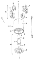
図1は、電気モータ40の分解斜視図である。電気モータ40は、ステータ組立体10を有し、また、フレーム50と、ロータ組立体60を有する。フレーム50は、内壁51と、外壁52を有する。外壁52は、内壁51を包囲し、環状チャンネル54が、外壁52と内壁51の間に定められる。多数のディフューザベーン53が、環状チャンネル54の中を内壁51と外壁52の間に延びている。ロータ組立体60は、シャフト61と、磁石62と、軸受組立体63と、インペラ64を有する。組立てたとき、磁石62、軸受組立体63及びインペラ64は全て、締り嵌め及び接着剤の一方又はこれらの組合せによってシャフト61に直接固定されている。磁石62は、永久磁石ブラシレスモータにおいて一般に使用される種類の接合式永久磁石であり、図示の例では、磁石22は、4極永久磁石である。
FIG. 1 is an exploded perspective view of the
ロータ組立体60は、内壁51によってフレーム50内に支持される。軸受組立体63は、内壁51によって定められるボアの内側に固定され、フレーム50の内壁51は、軸受組立体63の周りの保護スリーブとして作用する。これにより、軸受組立体63が別々の保護スリーブを有する必要性をなくし、モータ40の寸法及び重量を減少させるのに役立つ。モータ40を完全に組立てると、磁石62は、フレーム50の内壁51を越えて延び、磁石62の全体が、ステータ組立体10内に且つC字形のコア20同士の間に位置決めされる。
The
明確のために、用語「軸線方向」は、図1の軸線A−Aによって示すように、モータ40の回転軸線に沿って延びる軸線の方向を意味することを意図している。加えて、本明細書において述べる方向の用語「上流」及び「下流」は、使用時にモータの中を通る空気流の方向を指し、図3において両方向矢印によってさらに明瞭にされる。
For clarity, the term “axial direction” is intended to mean the direction of an axis that extends along the rotational axis of the
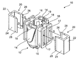
図2は、ステータ組立体10を示す。ステータ組立体10は、2つのC字形のステータコア20と、ボビン組立体12を有する。C字形のステータコア20(C字形コアとも呼ぶ)の各々は、後部22と、後部22から延びる2つの極アーム24を含む。極面26が、極アーム24の各々の端面にある。溝28が、極面26の後方の極アーム24の外側の面にあり、極アーム24の軸線方向長さに沿って延びる。溝28は、接着剤が集まることができる容積を有し、この領域は、強固な接着剤結合がC字形コア20とボビン組立体12の間にあることを確保する。極面26を極アーム24の端部に有することによって、磁石がC字形コア20の近くで回転するときに変動する磁力の下で、極アーム24が曲がる可能性があることを理解すべきである。磁石に対する極面の移動により、モータの性能に悪影響を及ぼすことがある。従って、溝28を極面26に近接して位置決めすることによって、極面26の任意の移動が最小に保たれる。用語「近接」は、ロータ組立体の磁石がC字形コア20の近くで回転しているとき、溝28と極面26が、極面26の任意の移動を接着剤結合により最小にするのに十分互いに近くに位置決めされることを意味する。
FIG. 2 shows the
変形例として、極アーム24は、溝を有しなくてもよい。この例では、接着剤が、各極アームの外側面のかなりの部分に沿って設けられ、大きい結合領域が極アームとボビン組立体との間に設けられるのがよい。これにより、ロータ磁石が回転しているときに極面26の任意の移動を最小にするのに等しく効果的である強固な接着剤結合が得られる。
As a modification, the
C字形コア20の各々において、一方の極アーム24の端部のところの極面26は、同じC字形コア20の他方の極アームの端部のところの極面26と異なる。これらの極面26を非対称にする理由は、突出を増大させるためである。増大させた突出により、ロータが回転していないときにロータがステータコアに対する特定の位置に停止することを促進させ、モータを特定の方向に再始動させることが容易である。C字形コア20の両方の極面26を同じにしたとすると、モータを始動させるとき、ロータが所望の方向に回転することを促進させることが困難になる。
In each of the C-shaped
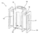
ボビン組立体12は、2つのボビン部分14を有する。単一のボビン部分14をさらに詳細に図3に示す。ボビン部分14の各々は、ボビン部分の中央部から外向きに延びる2つの中空のボビンアーム16を含み、中空のボビンアーム16の各々は、その端部にフランジ34を含む。ボビンアーム16は、C字形コア20から極アーム24を受入れることができるスロット17を有する。磁界をC字形コア20に誘導するための巻線(図示せず)が、ボビンアーム16に巻かれ、フランジ34は、巻線をボビンアーム16上の適所に保つように作用する。ボビンアーム16の中を延びるスロット17により、C字形コア20の極アーム24がボビン組立体12のスロットの中に入ることを可能にし、巻線が、各極アーム24の周りに位置決めされる。図2は、両方のボビン部分14を互いに当接させて、矢印Sによって示すようにC字形コア20をボビン組立体12内に滑り込ませることによる、ステータ組立体10を組立てる仕方を示す。C字形コア20は、C字形コア20の各々が両方のボビン部分14を橋渡しするように配列され、一方の極アーム24が、第1のボビン部分のスロットの中を延び、他方の極アーム24が、第2のボビン部分のスロットの中を延びている。
The
C字形コア20が2つのボビン部分14を橋渡しすることによって、2つのボビン部分14は、C字形ステータコア20によって互いにしっかりと保持される。2つの別々のボビン部分14を設ける1つの理由は、ボビン部分が分離されているとき、巻線をボビンアーム16に巻きやすいからである。図から分かるように、2つのボビン部分14がそれらの間に隙間がないように互いに位置決めされるとき、フランジ34は互いに当接する。ボビン組立体12が2つの分離可能な部分として設けられていないと、巻線ワイヤをボビンアーム16の間の隙間に通す必要があるので、巻線をボビンアーム16に巻くことが困難になり且つ費用がかかるようになるであろう。
As the C-shaped
各ボビン部分14は、その中央部に、半円筒形凹部15を含み、2つのボビン部分14を一緒にするとき、半円筒形凹部15の各々は、ボビン組立体12の中心を貫通する円筒形ボア18の一部を形成する。各ボビン部分14の半円筒形凹部15は、2つの窓32を有し、2つの窓32は、ボビン組立体12の内側における各ボビンアーム16のスロット17の終端を構成する。ステータ組立体10を完全に組立てると、C字形コア20の極面26は、窓32のところに位置決めされ、ボア18の壁の一部を形成する。
Each
ボビン組立体12はさらに、ステータ組立体10をモータ内に固定することを可能にする固定用凹部19を有する。固定用凹部19は、ボビン部分14の各々の中央部分に形成されたボビン組立体12の中央部分に位置する。ボビン部分14の各々は、1つの固定用凹部19を有する。
The
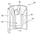
フレーム50の断面を図4に示す。内壁51は円筒形であり、ボア55を有する。モータ40を組立てるとき、内壁51がロータ組立体60をボア55内に支持する。加えて、内壁51は、その一方の端部から軸線方向に延びるラグ56を有する。特に、ラグ56は、軸線方向の下流方向に延びている。ラグ56は、ステータ組立体10をフレーム50に固定するためにステータ組立体10を容易に取付けることができる取付け箇所を構成する。図4は、単一のラグ56を示しているけれども、ステータ組立体10に設けられる固定用凹部19の数及びモータのその他の要求に応じて、多数のラグ56を設けてもよい。ラグ56は、それらがボビン組立体12の固定用凹部19の内側に受入れられるように位置決めされる。ラグ56及び固定用凹部19は、ラグが固定用凹部の内側にぴったり嵌って締り嵌めを形成するように適当に寸法決めされるのがよい。変形例として、固定用凹部19は、ラグ56及び接着剤の容積を収容することができるのに十分大きくてもよい。この例では、モータ40の組立て中、ステータ組立体10とフレーム50を一緒にする前、接着剤を、固定用凹部の内側に付与してもよいし、ラグの外側に付与してもよいし、その両方に付与してもよい。
A cross section of the
本明細書で使用する用語「ラグ」は、形態、寸法又は形状に関して限定していることを意図していない。実際、用語「ラグ」は、2つのものを一緒に固定するために別の部品の凹部に挿入することができる任意の突出部を含むことを理解すべきである。 The term “lag” as used herein is not intended to be limiting with respect to form, size or shape. Indeed, it should be understood that the term “lag” includes any protrusion that can be inserted into a recess in another part to secure the two together.
ボビン組立体12の固定用凹部19により、ステータ組立体10をモータ40のフレーム50にボビン組立体12のところで固定することを可能にし、C字形コア20自体を取付けのために使用しない。従って、C字形コア20は、それらが構造的役割を担う必要がないので、それほど大きく作られる必要がない。これにより、ステータ組立体、従ってモータ全体の、コスト及び重量を低減させるのに役立つ。加えて、C字形コアは、取付けのための任意の貫通孔又は切欠き部分を包含する必要がなく、従って、C字形コアは、貫通孔又は切欠き部分によって生じ得るそれらと関連した磁気飽和の任意の問題に苦しまない。
The fixing
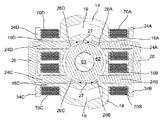
図5は、組立てられたステータ組立体10とロータ組立体60の断面を示す。ボビン部分14の各々の中央部は、固定用凹部19を含む。一方のボビン部分14は、ボビンアーム16A、16Dを含み、他方のボビン部分14は、ボビンアーム16B、16Cを含む。巻線70A〜70Dがそれぞれ、ボビンアーム16A〜16Dの周りに巻かれ、フランジ34A〜34Dによって適所に保持される。2つのC字形コア20が設けられ、第1のC字形コアは、極アーム24A、24Bを含み、他方のC字形コアは、極アーム24C、24Dを含む。極面26A〜26Dがそれぞれ、極アーム24A〜24Dの端部に設けられる。C字形コア20は、極アーム24A〜24Dが中空のボビンアーム16A〜16Dのスロットの中を延びるように、且つ、C字形コア20の各々が両方のボビン部分14を橋渡しするように位置決めされる。例えば、図5に示すように、C字形コアのうちの一方の極アーム24Aは、一方のボビン部分のボビンアーム16Aのスロットの中を延び、同じC字形コアの極アーム24Bは、異なるボビン部分のボビンアーム16Bのスロットの中を延びる。2つのC字形コアのうちの他方についても、同じことが当てはまり、極アーム24Cは、一方のボビン部分のボビンアーム16Cのスロットの中を延び、極アーム24Dは、他方のボビン部分のボビンアーム16Dのスロットの中を延びる。
FIG. 5 shows a cross section of the assembled
従って、C字形コアをこのように配列すれば、巻線70A〜70Dはそれぞれ、極アーム24A〜24Dの周りに位置決めされ、電流が巻線70A〜70Dの中を流れるとき、磁界がC字形コア20を介して極面26A〜26Dに誘導される。
Thus, with this arrangement of C-shaped cores,
ロータ組立体60のシャフト61及び磁石62は、ステータ組立体10の内側においてC字形コア20の間に位置決めされ且つボビン部分14の2つの半円筒形凹部によって形成された円筒形ボア内に位置決めされる。磁石62は、モータ40の作動中に4つの極面26A〜26Dと磁気的に相互作用する4つの極(図示せず)を有する。
The
凹部19をボビン部分14の各々の中央部に有することによって、凹部19は、極と極の間の空所であるスロット開口部27の近くに位置決めされる。これにより、ステータ組立体内の空間を効率的に使用する。C字形コア20の極アーム24の周りにおけるボビン組立体12内の空間は、巻線によって占められる。しかしながら、スロット開口部27の周りの空間は、典型的には、かかる任意の要求はない。ステータ組立体の外側の周囲に外部からの取付け機構が不要であるため、この空間を凹部19のために利用することにより、ステータ組立体をさらに小型にすることができる。これにより、ステータ組立体の外側の周りの空気流の制約を低減することもできる。
By having a
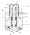
図6は、組立てられたモータ40の断面を示す。この断面は、スロット開口部27を横切るようにモータを横断し、この場合、いずれのC字形コアも見ることができない。しかしながら、この断面は、各ボビン部分14の中央部を直接通過し、この場合、ボビン組立体12の凹部19の内部に固定されたフレーム50のラグ56を見ることができる。凹部19内のラグ56の周りに空間があり、この空間は、凹部19とラグ56を一緒に固定する接着剤(図示せず)を収容する。
FIG. 6 shows a cross section of the assembled
ステータ組立体10は、内壁51の下流端部に固定され、インペラ64は、内壁51の上流端部のところでシャフト61に固定される。従って、インペラによって発生した空気流は、フレーム50の中を流れ、ステータ組立体10を通る。従って、この空気流は、作動中にモータ40の巻線を冷却するのに役立つ。
The
磁石62は、シャフト61に固定され、C字形コア(図示せず)と軸線方向に整列するように、ステータ組立体12のボア18内に位置決めされる。軸受組立体63は、1対の軸受72a、72bと、これらの軸受72a、72bを分離させるばね73を有する。ばね73は、軸受72a、72bの外輪の各々に予圧荷重を加えるように作用し、使用中の軸受の摩耗を低減させる。ワッシャが、ばね73と軸受72a、72bの各々との間に設けられてもよい。
以上、特定の実施形態を説明したが、特許請求の範囲によって定められるように、様々の修正を、本発明の範囲から逸脱することなしに行ってもよいことを理解すべきである。 While specific embodiments have been described above, it should be understood that various modifications can be made without departing from the scope of the invention as defined by the claims.
10 ステータ組立体
12 ボビン組立体
14 ボビン部分
16 ボビンアーム
19 固定用凹部
20 ステータコア
27 スロット開口部
40 電気モータ
50 フレーム
51 内壁
56 ラグ
60 ロータ組立体
64 インペラ
DESCRIPTION OF
Claims (11)
フレームと、
ステータ組立体と、を有し、
前記ステータ組立体は、ボビン組立体と、少なくとも1つのC字形ステータコアを有し、
前記フレームは、少なくとも1つのラグを含み、前記ボビン組立体は、少なくとも1つの凹部を含み、
前記ステータ組立体は、前記ラグを前記ボビン組立体の凹部内に固定することによって、前記フレームに固定される、電気モータ。 An electric motor,
Frame,
A stator assembly,
The stator assembly includes a bobbin assembly and at least one C-shaped stator core;
The frame includes at least one lug, the bobbin assembly includes at least one recess;
The stator assembly is an electric motor fixed to the frame by fixing the lug in a recess in the bobbin assembly.
Applications Claiming Priority (2)
| Application Number | Priority Date | Filing Date | Title |
|---|---|---|---|
| GB1521890.2A GB2545268B (en) | 2015-12-11 | 2015-12-11 | An electric motor |
| GB1521890.2 | 2015-12-11 |
Related Child Applications (1)
| Application Number | Title | Priority Date | Filing Date |
|---|---|---|---|
| JP2019059831A Division JP6832972B2 (en) | 2015-12-11 | 2019-03-27 | Electric motor |
Publications (2)
| Publication Number | Publication Date |
|---|---|
| JP2017123771A true JP2017123771A (en) | 2017-07-13 |
| JP6505658B2 JP6505658B2 (en) | 2019-04-24 |
Family
ID=55274596
Family Applications (2)
| Application Number | Title | Priority Date | Filing Date |
|---|---|---|---|
| JP2016240182A Active JP6505658B2 (en) | 2015-12-11 | 2016-12-12 | Electric motor |
| JP2019059831A Active JP6832972B2 (en) | 2015-12-11 | 2019-03-27 | Electric motor |
Family Applications After (1)
| Application Number | Title | Priority Date | Filing Date |
|---|---|---|---|
| JP2019059831A Active JP6832972B2 (en) | 2015-12-11 | 2019-03-27 | Electric motor |
Country Status (9)
| Country | Link |
|---|---|
| US (1) | US11183895B2 (en) |
| EP (1) | EP3387739A1 (en) |
| JP (2) | JP6505658B2 (en) |
| KR (1) | KR102090641B1 (en) |
| CN (2) | CN106972654B (en) |
| AU (1) | AU2016366624B2 (en) |
| GB (1) | GB2545268B (en) |
| RU (1) | RU2699043C1 (en) |
| WO (1) | WO2017098201A1 (en) |
Cited By (1)
| Publication number | Priority date | Publication date | Assignee | Title |
|---|---|---|---|---|
| JP2023502959A (en) * | 2020-05-15 | 2023-01-26 | グアンドン ウェリング モーター マニュファクチュアリング カンパニー リミテッド | Rotating electric machine and fan |
Families Citing this family (17)
| Publication number | Priority date | Publication date | Assignee | Title |
|---|---|---|---|---|
| GB2545413B (en) | 2015-12-11 | 2019-04-03 | Dyson Technology Ltd | A stator assembly |
| GB2545268B (en) * | 2015-12-11 | 2019-04-03 | Dyson Technology Ltd | An electric motor |
| GB2563616B (en) * | 2017-06-20 | 2021-03-10 | Dyson Technology Ltd | A stator assembly |
| GB2563613B (en) | 2017-06-20 | 2021-10-20 | Dyson Technology Ltd | A brushless motor and stator therefor |
| GB2563614B (en) * | 2017-06-20 | 2020-06-17 | Dyson Technology Ltd | Brushless motor |
| GB2563612B (en) * | 2017-06-20 | 2020-09-23 | Dyson Technology Ltd | An electric motor |
| CN112087073A (en) * | 2019-06-14 | 2020-12-15 | 中山市盟拓机电有限公司 | Hollow cup motor with simple structure |
| CN110224564A (en) * | 2019-06-17 | 2019-09-10 | 中山市盟拓机电有限公司 | A kind of section space-efficient high-speed motor |
| EP3796521B1 (en) * | 2019-09-20 | 2022-08-31 | Once Top Motor Manufacture Co.,Ltd. | A single-phase brushless high-speed motor |
| KR102277265B1 (en) * | 2019-10-29 | 2021-07-14 | 엘지전자 주식회사 | Motor assembly |
| KR102840723B1 (en) * | 2020-04-27 | 2025-07-31 | 엘지전자 주식회사 | Motor assembly |
| KR102797009B1 (en) * | 2020-05-08 | 2025-04-18 | 엘지전자 주식회사 | Motor assembly |
| KR102814546B1 (en) | 2020-05-08 | 2025-05-29 | 엘지전자 주식회사 | Motor assembly |
| CN113675984B (en) * | 2020-05-15 | 2022-08-26 | 广东威灵电机制造有限公司 | Rotating electrical machine and fan |
| KR102824015B1 (en) | 2020-07-28 | 2025-06-23 | 엘지전자 주식회사 | Fan motor and hair dryer including the same |
| KR102524011B1 (en) * | 2020-11-30 | 2023-04-19 | 서울대학교산학협력단 | Motor apparatus |
| KR20240148258A (en) * | 2023-04-03 | 2024-10-11 | 레비트로닉스 게엠베하 | An electromagnetic rotary drive and a centrifugal pump |
Citations (5)
| Publication number | Priority date | Publication date | Assignee | Title |
|---|---|---|---|---|
| JP2001194190A (en) * | 1999-10-27 | 2001-07-19 | Denso Corp | Pointer instrument |
| JP2007295771A (en) * | 2006-04-27 | 2007-11-08 | Nidec Copal Corp | Electromagnetic actuator and blade drive unit for camera |
| JP2013201893A (en) * | 2012-03-23 | 2013-10-03 | Dyson Technology Ltd | Stator for electrical machine |
| GB2512772A (en) * | 2009-03-03 | 2014-10-08 | Dyson Technology Ltd | Electric machine |
| JP2015097468A (en) * | 2013-11-15 | 2015-05-21 | 日本電産サンキョー株式会社 | Motor |
Family Cites Families (50)
| Publication number | Priority date | Publication date | Assignee | Title |
|---|---|---|---|---|
| BE552952A (en) | 1956-03-12 | |||
| US3495111A (en) * | 1967-12-04 | 1970-02-10 | Tri Tech | Small permanent magnet rotor shaded pole motor |
| US3593049A (en) | 1969-10-02 | 1971-07-13 | Siemens Ag | Dc midget motor free of commutator and slip rings |
| CA1103298A (en) * | 1977-02-25 | 1981-06-16 | Masami Uchiyama | Electric motor with discrete rotor position and speed sensors |
| JPS5448306A (en) | 1977-08-29 | 1979-04-16 | Howa Mach Ltd | Valve device of reciprocating compressor |
| US4166265A (en) | 1978-02-03 | 1979-08-28 | Amp Incorporated | Coil bobbins and termination of coil windings |
| JPS6026447A (en) | 1983-07-20 | 1985-02-09 | Matsushita Electric Ind Co Ltd | Permanent magnet rotor type synchronous motor |
| JPS6026446A (en) * | 1983-07-20 | 1985-02-09 | Matsushita Electric Ind Co Ltd | Permanent magnet rotor type synchronous motor |
| JPS60134401A (en) | 1983-12-22 | 1985-07-17 | 株式会社デンソー | External resistor of ignition coil for internal combustion engine |
| JPS60144135A (en) | 1983-12-29 | 1985-07-30 | Matsushita Electric Ind Co Ltd | Permanent magnet rotor type synchronous motor |
| JPS6294612U (en) * | 1985-12-03 | 1987-06-17 | ||
| JPH0744803B2 (en) | 1989-12-27 | 1995-05-15 | 三菱電機株式会社 | Electric motor |
| JP2534683Y2 (en) * | 1990-07-16 | 1997-05-07 | 愛三工業株式会社 | Step motor terminal fixing structure |
| NL9002222A (en) * | 1990-10-12 | 1992-05-06 | Airpax Sa Nv | ELECTROMOTOR AND HOLDER FOR USE IN THE ELECTROMOTOR. |
| US5275141A (en) | 1991-05-31 | 1994-01-04 | Asmo, Co., Ltd. | Actuator |
| US6348752B1 (en) | 1992-04-06 | 2002-02-19 | General Electric Company | Integral motor and control |
| USRE36545E (en) * | 1993-09-30 | 2000-02-01 | Steiner; Robert E. | Twin bobbin four pole motors and methods for making same |
| US5604971A (en) | 1993-09-30 | 1997-02-25 | Steiner; Robert E. | manufacturing method for variable laminations used in electro-magnetic induction devices |
| US5627424A (en) * | 1993-09-30 | 1997-05-06 | Steiner; Robert E. | Twin bobbin four pole motors and methods for making same |
| JPH08322226A (en) | 1995-03-20 | 1996-12-03 | Asmo Co Ltd | Rotary actuator |
| JP2779382B2 (en) | 1995-09-28 | 1998-07-23 | セイコークロック株式会社 | Coil bobbin |
| US5943760A (en) | 1996-02-09 | 1999-08-31 | Eastman Kodak Company | Stepper motor and method of manufacture |
| GB2362268B (en) * | 2000-05-12 | 2005-05-11 | Notetry Ltd | Electrical machine |
| JP2001327151A (en) | 2000-05-15 | 2001-11-22 | Canon Inc | Electromagnetic drive device and electromagnetic drive diaphragm device |
| JP2001327148A (en) | 2000-05-15 | 2001-11-22 | Canon Inc | Electromagnetic drive motor |
| JP3711252B2 (en) * | 2001-06-13 | 2005-11-02 | ミネベア株式会社 | Claw pole type stepping motor |
| EP1437817B1 (en) * | 2003-01-10 | 2013-03-13 | Askoll Holding S.r.l. | Synchronous electric motor with a permanent magnet rotor and improved supporting spools for circulation pumps of heating and air-conditioning systems |
| JP2006191718A (en) * | 2004-12-28 | 2006-07-20 | Seiko Precision Inc | Stator, actuator, and method for manufacturing stator |
| ATE528838T1 (en) | 2005-08-30 | 2011-10-15 | Askoll Holding Srl | SINGLE PHASE PERMANENT MAGETIC SYNCHRONOUS MOTOR WITH IMPROVED STATOR STRUCTURE, ESPECIALLY FOR DRAINAGE PUMPS OF WASHING MACHINES AND SIMILAR HOUSEHOLD APPLIANCES |
| DE202006007808U1 (en) | 2005-12-16 | 2006-08-10 | BSH Bosch und Siemens Hausgeräte GmbH | Stator terminal plate for universal motor in e.g. washing machine, has contact units arranged in connector tub, for electrical contacting of internal electrical component of commutator motor |
| KR101261084B1 (en) * | 2007-05-31 | 2013-05-06 | 니혼 덴산 산쿄 가부시키가이샤 | Motor |
| JP2008301636A (en) | 2007-05-31 | 2008-12-11 | Nidec Sankyo Corp | Motor |
| EP2160954A1 (en) | 2008-09-08 | 2010-03-10 | Koninklijke Philips Electronics N.V. | Hair dryer, an attachment for a hair dryer, and a hair dryer provided with such an attachment |
| GB2468310B (en) | 2009-03-03 | 2015-01-07 | Dyson Technology Ltd | Stator core |
| DE102010034890A1 (en) * | 2009-08-21 | 2011-03-10 | Johnson Electric S.A. | Universal motor |
| EP2299566A1 (en) | 2009-09-17 | 2011-03-23 | PM-Generators GmbH | Wind or water energy assembly |
| RU109349U1 (en) * | 2011-03-16 | 2011-10-10 | Сергей Михайлович Есаков | MAGNETO-ELECTRIC GENERATOR |
| GB2495545B (en) * | 2011-10-14 | 2014-11-05 | Dyson Technology Ltd | Stator for an electrical machine |
| US9172283B2 (en) * | 2012-01-17 | 2015-10-27 | Regal Beloit America, Inc. | Electric motor |
| US20140132106A1 (en) | 2012-11-09 | 2014-05-15 | Nidec Motor Corporation | Motor having bridged stator with search coil |
| US9263918B2 (en) * | 2012-11-09 | 2016-02-16 | Nidec Motor Corporation | Connection for motor stator segments |
| JP6066713B2 (en) * | 2012-12-19 | 2017-01-25 | ミネベア株式会社 | Stepping motor |
| GB2513664B (en) * | 2013-05-03 | 2016-01-06 | Dyson Technology Ltd | Compressor |
| GB2513661B (en) | 2013-05-03 | 2016-03-16 | Dyson Technology Ltd | Vibration isolation mount |
| JP2015095947A (en) | 2013-11-12 | 2015-05-18 | ミネベア株式会社 | Pm type stepping motor |
| JP6208031B2 (en) * | 2014-01-30 | 2017-10-04 | 東芝ライフスタイル株式会社 | Brushless motor and manufacturing method thereof |
| JP6310572B2 (en) * | 2014-04-16 | 2018-04-11 | コーニンクレッカ フィリップス エヌ ヴェKoninklijke Philips N.V. | Electric toothbrush and integrated charging coil bobbin for electric toothbrush |
| DE102016118507A1 (en) | 2015-09-30 | 2017-03-30 | Johnson Electric S.A. | Brushless motor |
| GB2545268B (en) * | 2015-12-11 | 2019-04-03 | Dyson Technology Ltd | An electric motor |
| GB2545413B (en) | 2015-12-11 | 2019-04-03 | Dyson Technology Ltd | A stator assembly |
-
2015
- 2015-12-11 GB GB1521890.2A patent/GB2545268B/en active Active
-
2016
- 2016-11-25 EP EP16804871.8A patent/EP3387739A1/en not_active Withdrawn
- 2016-11-25 WO PCT/GB2016/053702 patent/WO2017098201A1/en not_active Ceased
- 2016-11-25 AU AU2016366624A patent/AU2016366624B2/en not_active Ceased
- 2016-11-25 RU RU2018123541A patent/RU2699043C1/en not_active IP Right Cessation
- 2016-11-25 KR KR1020187017209A patent/KR102090641B1/en active Active
- 2016-12-12 US US15/376,351 patent/US11183895B2/en active Active
- 2016-12-12 JP JP2016240182A patent/JP6505658B2/en active Active
- 2016-12-12 CN CN201611141824.6A patent/CN106972654B/en active Active
- 2016-12-12 CN CN201621361083.8U patent/CN206272359U/en not_active Withdrawn - After Issue
-
2019
- 2019-03-27 JP JP2019059831A patent/JP6832972B2/en active Active
Patent Citations (5)
| Publication number | Priority date | Publication date | Assignee | Title |
|---|---|---|---|---|
| JP2001194190A (en) * | 1999-10-27 | 2001-07-19 | Denso Corp | Pointer instrument |
| JP2007295771A (en) * | 2006-04-27 | 2007-11-08 | Nidec Copal Corp | Electromagnetic actuator and blade drive unit for camera |
| GB2512772A (en) * | 2009-03-03 | 2014-10-08 | Dyson Technology Ltd | Electric machine |
| JP2013201893A (en) * | 2012-03-23 | 2013-10-03 | Dyson Technology Ltd | Stator for electrical machine |
| JP2015097468A (en) * | 2013-11-15 | 2015-05-21 | 日本電産サンキョー株式会社 | Motor |
Cited By (3)
| Publication number | Priority date | Publication date | Assignee | Title |
|---|---|---|---|---|
| JP2023502959A (en) * | 2020-05-15 | 2023-01-26 | グアンドン ウェリング モーター マニュファクチュアリング カンパニー リミテッド | Rotating electric machine and fan |
| JP7334352B2 (en) | 2020-05-15 | 2023-08-28 | グアンドン ウェリング モーター マニュファクチュアリング カンパニー リミテッド | Rotating electric machine and fan |
| US12113422B2 (en) | 2020-05-15 | 2024-10-08 | Guangdong Welling Motor Manufacturing Co., Ltd. | Rotating motor and fan |
Also Published As
| Publication number | Publication date |
|---|---|
| GB2545268A (en) | 2017-06-14 |
| CN206272359U (en) | 2017-06-20 |
| US20170170697A1 (en) | 2017-06-15 |
| CN106972654B (en) | 2020-03-03 |
| CN106972654A (en) | 2017-07-21 |
| JP6832972B2 (en) | 2021-02-24 |
| GB201521890D0 (en) | 2016-01-27 |
| KR20180073703A (en) | 2018-07-02 |
| US11183895B2 (en) | 2021-11-23 |
| KR102090641B1 (en) | 2020-03-18 |
| JP6505658B2 (en) | 2019-04-24 |
| WO2017098201A1 (en) | 2017-06-15 |
| GB2545268B (en) | 2019-04-03 |
| AU2016366624B2 (en) | 2019-02-28 |
| JP2019097388A (en) | 2019-06-20 |
| EP3387739A1 (en) | 2018-10-17 |
| AU2016366624A1 (en) | 2018-06-07 |
| RU2699043C1 (en) | 2019-09-03 |
Similar Documents
| Publication | Publication Date | Title |
|---|---|---|
| JP6832972B2 (en) | Electric motor | |
| JP6416178B2 (en) | Stator assembly | |
| KR102282429B1 (en) | electric motor | |
| JP7523958B2 (en) | Brushless motor | |
| JP2013046571A (en) | Brushless motor | |
| JP2019009986A (en) | Brushless motor and stator therefor | |
| WO2020230507A1 (en) | Rotor and motor provided with same |
Legal Events
| Date | Code | Title | Description |
|---|---|---|---|
| A621 | Written request for application examination |
Free format text: JAPANESE INTERMEDIATE CODE: A621 Effective date: 20170411 |
|
| RD04 | Notification of resignation of power of attorney |
Free format text: JAPANESE INTERMEDIATE CODE: A7424 Effective date: 20170426 |
|
| A131 | Notification of reasons for refusal |
Free format text: JAPANESE INTERMEDIATE CODE: A131 Effective date: 20180528 |
|
| A131 | Notification of reasons for refusal |
Free format text: JAPANESE INTERMEDIATE CODE: A131 Effective date: 20180918 |
|
| A601 | Written request for extension of time |
Free format text: JAPANESE INTERMEDIATE CODE: A601 Effective date: 20181212 |
|
| A521 | Request for written amendment filed |
Free format text: JAPANESE INTERMEDIATE CODE: A523 Effective date: 20190215 |
|
| TRDD | Decision of grant or rejection written | ||
| A01 | Written decision to grant a patent or to grant a registration (utility model) |
Free format text: JAPANESE INTERMEDIATE CODE: A01 Effective date: 20190228 |
|
| A61 | First payment of annual fees (during grant procedure) |
Free format text: JAPANESE INTERMEDIATE CODE: A61 Effective date: 20190327 |
|
| R150 | Certificate of patent or registration of utility model |
Ref document number: 6505658 Country of ref document: JP Free format text: JAPANESE INTERMEDIATE CODE: R150 |
|
| R250 | Receipt of annual fees |
Free format text: JAPANESE INTERMEDIATE CODE: R250 |
|
| R250 | Receipt of annual fees |
Free format text: JAPANESE INTERMEDIATE CODE: R250 |
|
| R250 | Receipt of annual fees |
Free format text: JAPANESE INTERMEDIATE CODE: R250 |
|
| R250 | Receipt of annual fees |
Free format text: JAPANESE INTERMEDIATE CODE: R250 |
|
| R250 | Receipt of annual fees |
Free format text: JAPANESE INTERMEDIATE CODE: R250 |