JP2017123722A - Power supply apparatus, power supply control method, and program - Google Patents
Power supply apparatus, power supply control method, and program Download PDFInfo
- Publication number
- JP2017123722A JP2017123722A JP2016001249A JP2016001249A JP2017123722A JP 2017123722 A JP2017123722 A JP 2017123722A JP 2016001249 A JP2016001249 A JP 2016001249A JP 2016001249 A JP2016001249 A JP 2016001249A JP 2017123722 A JP2017123722 A JP 2017123722A
- Authority
- JP
- Japan
- Prior art keywords
- power
- receiving device
- power supply
- received
- power receiving
- Prior art date
- Legal status (The legal status is an assumption and is not a legal conclusion. Google has not performed a legal analysis and makes no representation as to the accuracy of the status listed.)
- Pending
Links
Images
Landscapes
- Charge And Discharge Circuits For Batteries Or The Like (AREA)
Abstract
Description
本発明は、電磁誘導方式や共鳴方式等、非接触で給電可能な給電装置に関する発明で、特に、複数の給電部を具えた給電装置に関するものである。 The present invention relates to a power supply device that can supply power without contact, such as an electromagnetic induction method or a resonance method, and particularly relates to a power supply device including a plurality of power supply units.
従来、Qi(登録商標)等の電磁誘導方式や、NFC,Rezence(登録商標)等の共鳴方式等、様々なワイヤレス充電に関する規格が提案されている。また、これら複数の充電方式に対応した給電器に関しても同様に提案が行われている。特許文献1には、複数アンテナによる給電電力制御を行い、人体検出時に給電電力を低減する技術が開示されている。 Conventionally, various standards relating to wireless charging such as an electromagnetic induction method such as Qi (registered trademark) and a resonance method such as NFC and Resonance (registered trademark) have been proposed. In addition, proposals have also been made for power feeders that support these multiple charging methods. Japanese Patent Application Laid-Open No. 2004-133620 discloses a technique for performing power supply control using a plurality of antennas and reducing the power supply when detecting a human body.
しかしながら、複数の方式に対応したマルチ給電パッドでは、給電に係る複数の方式それぞれに対応する給電エリアが重ならないよう給電アンテナを配置すると、給電パッドが大きくなってしまう。一方、給電パッドの小型化を図るため、各方式の給電エリアが重なるよう給電アンテナを配置すると、重なったエリアに置かれた受電装置が発熱する可能性があり、複数の方式で同時に給電することができない。したがって、いずれかの方式の給電を停止する必要があるが、その結果、給電パッド上に置かれた他の受電装置への給電が停止されてしまう場合がある。 However, in a multi-feed pad corresponding to a plurality of systems, if the feed antennas are arranged so that the feed areas corresponding to each of the plurality of systems related to power feeding do not overlap, the feed pad becomes large. On the other hand, in order to reduce the size of the power supply pad, if the power supply antennas are arranged so that the power supply areas of each method overlap, there is a possibility that the power receiving device placed in the overlapped area will generate heat. I can't. Therefore, it is necessary to stop the power supply of any method, but as a result, the power supply to other power receiving devices placed on the power supply pad may be stopped.
本発明はこのような問題点に鑑みなされたもので、複数の方式それぞれに対応する受電装置以外の他の受電装置への給電の制限を少なくしつつ、複数の方式それぞれに対応する受電装置への給電を適切に行うことを目的とする。 The present invention has been made in view of such problems, and to a power receiving apparatus corresponding to each of a plurality of systems while reducing restrictions on power supply to other power receiving apparatuses other than the power receiving apparatus corresponding to each of the plurality of systems. The purpose is to properly supply power.
そこで、本発明は、給電装置であって、第1の方式により給電を行う第1の給電手段と、第2の方式により給電を行う第2の給電手段と、前記第1の方式及び前記第2の方式のうち少なくとも一方の方式で受電可能な受電装置が、受電可能な領域に存在することを検知する検知手段と、前記第1の方式及び前記第2の方式のいずれの方式でも受電可能な第1の受電装置が、前記第1の方式及び前記第2の方式のいずれの方式でも受電可能な第1の領域に存在することが検知された場合に、前記検知手段による、前記第1の方式及び前記第2の方式のいずれか一方で受電可能な領域における、受電装置の検知結果に基づいて、前記第1の方式及び前記第2の方式のうち何れか一方の方式による給電電力を制限する電力制御手段とを有することを特徴とする。 Therefore, the present invention is a power supply apparatus, wherein the first power supply unit that supplies power by the first method, the second power supply unit that supplies power by the second method, the first method, and the first method Detecting means for detecting that a power receiving device capable of receiving power in at least one of the two methods exists in a power receiving area, and receiving power by any of the first method and the second method. When it is detected that the first power receiving device is present in the first region where power can be received by either of the first method and the second method, Based on the detection result of the power receiving device in an area where power can be received by either of the above method or the second method, the power supplied by any one of the first method or the second method is obtained. Having power control means to limit And butterflies.
本発明によれば、複数の方式それぞれに対応する受電装置以外の他の受電装置への給電の制限を少なくしつつ、複数の方式それぞれに対応する受電装置への給電を適切に行うことができる。 According to the present invention, it is possible to appropriately perform power feeding to a power receiving device corresponding to each of a plurality of methods while reducing restrictions on power feeding to other power receiving devices other than the power receiving device corresponding to each of the plurality of methods. .
以下、本発明の実施形態について図面に基づいて説明する。 Hereinafter, embodiments of the present invention will be described with reference to the drawings.
本実施形態に係る給電システムは、給電装置と、複数の受電装置とを有している。給電装置は、受電装置に対し非接触で給電(送電)可能である。給電装置は、異なる複数の方式で給電を行うことができる。本実施形態においては、給電装置は、非接触の給電方式として、第1方式と第2方式による給電を行うことが可能である。本実施形態においては、給電システムは、第1方式及び第2方式の両方式に対応する第1受電装置と、第1方式に対応する第2受電装置と、第2方式に対応する第3受電装置とを有しているものとする。なお、第2受電装置は第2方式には対応しておらず、第3受電装置は、第1方式には対応していないものとする。以下、適宜、第1受電装置、第2受電装置及び第3受電装置を、受電装置と総称する。上述の第1方式の給電には、例えばQiを採用することができる。また、第2方式の給電には例えばNFCを採用することができる。なお、それぞれ互いに異なる規格であれば、他の規格を採用してもよい。 The power feeding system according to the present embodiment includes a power feeding device and a plurality of power receiving devices. The power feeding device can supply power (transmit power) in a non-contact manner to the power receiving device. The power feeding apparatus can perform power feeding using a plurality of different methods. In the present embodiment, the power feeding apparatus can perform power feeding by the first method and the second method as a non-contact power feeding method. In the present embodiment, the power feeding system includes a first power receiving device corresponding to both the first method and the second method, a second power receiving device corresponding to the first method, and a third power receiving device corresponding to the second method. Device. It is assumed that the second power receiving device does not support the second method, and the third power receiving device does not support the first method. Hereinafter, as appropriate, the first power receiving device, the second power receiving device, and the third power receiving device are collectively referred to as a power receiving device. For example, Qi can be adopted for the above-described first-type power supply. For example, NFC can be used for the second type of power supply. Note that other standards may be adopted as long as the standards are different from each other.
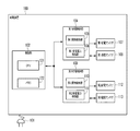
図1は、給電装置100を示す図である。給電装置100は、第1給電アンテナ107、第2給電アンテナ112の2つの給電アンテナを備えている。第1給電アンテナ107は、第1方式に対応し、第2給電アンテナ112は、第2方式に対応している。101は給電装置100の電源となる商用電源の入力部である。102は、給電装置100の制御を司る制御部である。制御部102は、CPU121と、メモリ122とを有する。制御部102は、第1給電制御部104及び第2給電制御部109の制御を司り、第1給電アンテナ107からの給電電力と、第2給電アンテナ112からの給電電力の選択制御等を行う。
FIG. 1 is a diagram illustrating a
104〜108は第1方式に対応するブロックであり、109〜113は第2方式に対応するブロックである。104は、第1方式の制御を司る第1給電制御部である。105は、第1方式の給電領域に配置された物体を異物か否か検知するための第1異物検知部である。第1異物検知部105は、給電効率の低下量や、電圧定在波比の変化量をもとに異物か否かの判定を行う。なお、異物検知の方法については、特開2012−170194号公報を参照することができる。
104 to 108 are blocks corresponding to the first method, and 109 to 113 are blocks corresponding to the second method.
106は、第1方式の給電領域に配置された受電装置の受電電力を検知するための第1受電電力検知部である。107は、第1方式により非接触で給電するための第1給電アンテナである。108は、受電装置と通信を行うための第1通信アンテナである。第1通信アンテナ108は、受電装置との間で要求電力や電池残量等に関する通信の送受信を行う。
Reference numeral 106 denotes a first received power detection unit for detecting the received power of the power receiving device arranged in the first type power supply region.
109は、第2の給電方式の制御を司る第2給電制御部である。110は、第2方式の給電領域に配置された物体を異物か否か検知するための第2異物検知部である。第2異物検知部110は、給電装置100の第2給電制御部109が、給電効率の低下量や、電圧定在波比の変化量をもとに異物か否かの判定を行う。111は、第2方式の給電領域に配置された受電装置の受電電力を検知するための第2受電電力検知部である。
112は、第2方式により非接触で給電するための第2給電アンテナである。113は、受電装置と通信を行うための第2通信アンテナである。第2通信アンテナ113は、受電装置との間で、要求電力や電池残量等に関する通信の送受信を行う。
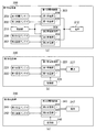
図2(a)は、第1受電装置200を示す図である。201〜212は第1受電装置200の構成要素である。201〜205は、第1方式により非接触で給電された電力を受電するための受電ブロックである。201は、第1方式により非接触で給電された電力を受電するための第1受電アンテナである。202は、給電装置100と通信を行うための第1通信アンテナである。第1通信アンテナ202は、給電装置100の第1通信アンテナ108を介して、第1受電装置200の要求電力や電池残量等に関する通信の送受信を行う。203は、第1方式による受電制御を司る第1受電制御部である。204は、第1方式により給電された電力を受電する第1受電部である。205は、第1受電部204により受電した電力を電池212に充電するための第1充電部である。
FIG. 2A is a diagram illustrating the first
206〜130は第2方式により非接触で給電された電力を受電するための受電ブロックである。206は、第2方式により非接触で給電された電力を受電するための第2受電アンテナである。207は、給電装置100と通信を行うための第2通信アンテナである。第2通信アンテナ207は、給電装置100の第2通信アンテナ113を介して、第1受電装置200の要求電力や電池残量等に関する通信の送受信を行う。208は、第2方式による受電制御を司る第2受電制御部である。209は、第2方式により給電された電力を受電する第2受電部である。210は、第2受電部209により受電した電力を電池212に充電するための第2充電部である。
Reference numerals 206 to 130 denote power receiving blocks for receiving electric power supplied in a non-contact manner by the second method. Reference numeral 206 denotes a second power receiving antenna for receiving electric power supplied in a non-contact manner by the second method. Reference numeral 207 denotes a second communication antenna for communicating with the
211は、制御部であり、第1受電装置200全体の制御を司る。制御部211は、CPUやメモリを有している。第1方式と第2方式による受電電力で、電池212に対し、同時に充電しないよう、第1受電制御部203、第2受電制御部208を制御する。212は第1受電装置200を動作させるための電池であり、第1充電部205、第2充電部210により充電動作が行われる。
A control unit 211 controls the entire first
図2(b)は、第2受電装置220を示す図である。221〜227は第2受電装置220の構成要素である。221〜225は第1方式により非接触で給電された電力を受電するための受電ブロックである。221は、第1方式により非接触で給電された電力を受電するための第1受電アンテナである。222は、給電装置100と通信を行うための第1通信アンテナである。第1通信アンテナ222は、給電装置100の第1通信アンテナ108を介して、第2受電装置220の要求電力や電池残量等に関する通信の送受信を行う。223は、第1方式による受電制御を司る第1受電制御部である。224は、第1方式により給電された電力を受電する第1受電部である。225は、第1受電部224により受電した電力を電池227に充電するための第1充電部である。226は、制御部であり、CPUやメモリを有している。制御部226は、第2受電装置220全体の制御を司る。227は第2受電装置220を動作させるための電池であり、第1充電部225により充電動作が行われる。
FIG. 2B is a diagram illustrating the second
図2(c)は、第3受電装置230を示す図である。241〜247は第3受電装置240の構成要素である。241〜245は第2方式により非接触で給電された電力を受電するための受電ブロックである。241は、第2方式により非接触で給電された電力を受電するための第2受電アンテナである。242は、給電装置100と通信を行うための第2通信アンテナである。第2通信アンテナ242は、給電装置100の第1通信アンテナ108を介して、第3受電装置240の要求電力や電池残量等に関する通信の送受信を行う。243は、第2方式による受電制御を司る第2受電制御部である。244は、第2方式により給電された電力を受電する第2受電部である。245は、第2受電部244により受電した電力を電池247に充電するための第2充電部である。246は、制御部であり、CPUやメモリを有している。制御部246は、第3受電装置240全体の制御を司る。247は第3受電装置240を動作させるための電池であり、第2充電部245により充電動作が行われる。
FIG. 2C shows the third power receiving device 230. Reference numerals 241 to 247 are components of the third
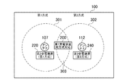
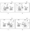
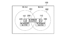
図3は、給電装置100と、受電装置200,220,240の位置関係の説明図である。図3に示すように、給電装置100は、第1給電アンテナ107と、第2給電アンテナ112が離れた位置に配置された、パット式の装置である。301は、第1給電アンテナ107による給電領域を示している。302は、第2給電アンテナ112による給電電力領域を示している。303は、第1給電アンテナ107による給電領域と第2給電アンテナ112による給電領域の重なり領域を示している。以下、領域301を第1領域、領域302を第2領域、領域303を第3領域と称することとする。ここで、第1領域301は、第1方式で受電可能な領域の一例であり、第2領域302は、第2方式で受電可能な領域の一例であり、第3領域303は、第1方式及び第2方式のいずれの方式でも受電可能な領域の一例である。
FIG. 3 is an explanatory diagram of a positional relationship between the
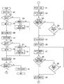
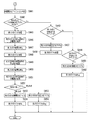
本実施形態に係る給電装置100は、第3領域303に位置する第1受電装置200に対し、第1方式及び第2方式を用いた同時給電を制限するような給電制御処理を行う。する。一方の給電電力が第1受電装置200において損失となり発熱する可能性があるためである。図4A及び図4Bは、給電装置100による給電制御処理を示すフローチャートである。なお、給電処理は、給電装置100のCPU121がメモリ122に格納されたプログラムを読み出し、このプログラムを実行することにより実現されるものである。
The
まず、給電装置100は、第1方式での給電および第2方式での給電について、それぞれ受電装置が存在するかどうかを確認する。S401において、CPU121は、第1給電アンテナ107による給電範囲に、受電装置や受電装置以外のものが存在するか否かを確認すべく、第1給電アンテナ107により給電を行うよう制御する。S402において、CPU121は、第1通信アンテナ108を介して、受電装置と通信が成立するか否かを確認する。CPU121は、通信が成立すると判断した場合には(S402でYes)、処理をS403へ進める。CPU121は、通信が成立しないと判断した場合には(S402でNo)、処理をS404へ進める。
First, the
S403において、CPU121は、受電装置が第1方式に対応しているものと判断し、受電装置固有の装置IDを受電装置から取得し、その後処理をS406へ進める。なお、本実施形態においては、給電装置100は、第1通信アンテナ108を介して、通信が成立した受電装置に対応するように、第1給電アンテナ107による給電を行う。つまり、給電可能な範囲に他の装置が存在していたとしても、通信が成立しない場合には受電装置として扱わず、異物と判断する。
In S403, the
S404において、CPU121は、第1異物検知部105に対し、異物検知を指示する。これに対応し、第1異物検知部105による異物検知が行われる。CPU121は、異物が検出されたと判断した場合には(S404でYes)、処理をS405へ進める。CPU121は、異物が検出されなかったと判断した場合には(S404でNo)、処理をS406へ進める。ここで、異物とは給電のための出力に影響を受けるものである。例えば、通信が成立しなかった別方式の受電装置等の導電体である。S405において、CPU121は、検出された異物による損失が無くなるまで給電電力を下げるよう設定し、その後処理をS406へ進める。なお、損失の有無については、例えば受電側で受け取った電力の情報を通信により受信し、給電電力の出力と比較することにより判断することができる。S406において、CPU121は、一旦、第1給電アンテナ107による給電を停止するよう制御する。
In step S <b> 404, the
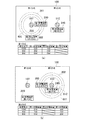
例えば、図5(a)に示すように、第1領域301に第1受電装置200及び第2受電装置220が存在する場合には、CPU121は、S403において、各受電装置200,220から装置IDを取得する。また、例えば図5(b)に示すように、第1領域301に異物500が存在する場合には、第1異物検知部105により異物500が検出される。そして、CPU121は、S405において、異物500による損失がなくなるまで給電電力を下げていく。そして、図7(b)に示すように、損失がなくなる給電領域710となるように給電電力を制限する。
For example, as shown in FIG. 5A, when the first
S406の処理の後、S407において、CPU121は、第2給電アンテナ112による給電領域に、受電装置や異物が存在するか否かを確認すべく、第2給電アンテナ112により給電を行うよう制御する。S408において、CPU121は、第2通信アンテナ113を介して、受電装置と通信が成立するか否かを確認する。CPU121は、通信が成立すると判断した場合には(S408でYes)、処理をS409へ進める。CPU121は、通信が成立しないと判断した場合には(S408でNo)、処理をS410へ進める。
After the process of S406, in S407, the
S409において、CPU121は、受電装置が第2方式に対応しているものと判断し、受電装置固有の装置IDを受電装置から取得し、その後処理をS412へ進める。なお、本実施形態においては、給電装置100は、第2通信アンテナ113を介して、通信が成立した受電装置に対応するように、第2給電アンテナ112による給電を行う。
In S409, the
S410において、CPU121は、第2異物検知部110に対し、異物検出を指示する。これに対応し、第2異物検知部110による異物検知が行われる。CPU121は、異物が検出されたと判断した場合には(S410でYes)、処理をS411へ進める。CPU121は、異物が検出されなかったと判断した場合には(S410でNo)、処理をS412へ進める。S411において、CPU121は、検出された異物による損失が無くなるまで給電電力を下げるよう設定し、その後処理をS412へ進める。S412において、CPU121は、一旦第2給電アンテナ112による給電を停止するよう制御する。
In S410, the
例えば図5(c)に示すように、第2領域302に第1受電装置200及び第3受電装置240が存在する場合には、CPU121は、S409において、各受電装置200,240から装置IDを取得する。また、例えば図5(d)に示すように、第2領域302に異物520が存在する場合には、第2異物検知部110により異物520が検出される。そして、CPU121は、S411において、異物520による損失がなくなるまで給電電力を下げていく。そして、図5(d)に示すように、損失がなくなる給電領域530となるように給電電力を制限する。S401からS412までの処理によって、給電装置100は、受電装置の存在および受電装置が対応する給電方式、そして、異物の存在と異物による損失がない給電範囲を決定する。
For example, as shown in FIG. 5C, when the first
続くS413において、CPU121は、第1方式及び第2方式の両方式に対応する受電装置が存在するか否かを確認する。例えば、図5の配置例では、第1受電装置200が検知される。具体的には、CPU121は、S403において取得した装置IDとS409において取得した装置IDを比較し、重複した装置IDが存在する場合に、この受電装置を両方式に対応する受電装置として検知する。なお、S403およびS409の両方で装置IDが取得できたことは、すなわち、その受電装置がアンテナ107およびアンテナ112と通信できる第3領域303に存在することになる。ここで、S403、S409及びS413の処理は、受電装置が受電可能な領域に存在することを検知する検知処理の一例である。
In subsequent S413, the
CPU121は、両方式に対応する受電装置が、第3領域303に存在すると判断した場合には(S413でYes)、処理をS421へ進める。CPU121は、両方式に対応する受電装置が第1領域303に存在しないと判断した場合には(S413でNo)、処理をS414へ進める。S414において、CPU121は、検出した受電装置の給電方式に従った給電制御を行う。なお、各受電装置への給電制御については、例えば、特開2009−219177号公報を参照することができる。
If the
以降の処理では、CPU121は、第3領域303に存在する両方式に対応する受電装置に対する給電を制御するための処理を行う。まず、第1方式の給電について処理を進める。S421において、CPU121は、第1方式で給電可能な最大電力で給電するよう制御する。なお、S405で異物検知により、電力を下げるよう設定されている場合は、異物に対する損失が発生しない範囲での最大電力とする。次に、S422において、CPU121は、第1方式の給電電力を1W下げるように制御する。なお、受電アンテナの受電電力は、給電アンテナからの給電電力に比例する関係にあるため、第1方式の給電電力を下げると、第1方式における受電装置の第1方式による受電電力もこれに比例して低下する。
In the subsequent processing, the
次に、S423において、CPU121は、両方式に対応する受電装置の受電電力を確認する。図5に示す配置例では、CPU121は、第1受電装置200の受電電力を確認する。具体的には、CPU121は、第1通信アンテナ108を介して、両方式に対応する受電装置に受電電力の問い合わせを行い、両方式に対応する受電装置から受電電力の通知を受信する。CPU121は、両方式に対応する受電装置の受電電力が閾値以下と判断した場合には(S423でYes)、処理をS425へ進める。CPU121は、受電電力が閾値よりも大きいと判断した場合には(S423でNo)、処理をS424へ進める。なお、本実施形態においては、閾値を0Wとする。
Next, in S423, the
S424において、CPU121は、第1方式の給電電力を確認する。CPU121は、給電電力が0Wであると判断した場合には(S424でYes)、処理をS425へ進める。S425において、CPU121は、第1方式による給電を停止するよう制御する。CPU121は、給電電力が0Wでない、すなわち0Wよりも大きいと判断した場合には(S424でNo)、処理をS422へ進める。すなわち、この場合、CPU121は、第1方式の給電電力を下げ、受電電力を確認する処理フローを、受電装置が受電する電力が閾値以下になるか、給電電力が0Wになるまで繰り返す。
In S424, the
なお、本実施形態においては、S423及びS424において、受電電力の閾値を0Wとしているが、閾値は実施形態に限定されるものではない。他の例としては、受電装置の最も消費電力の少ない動作モードの電力を閾値としてもよい。 In this embodiment, in S423 and S424, the threshold of received power is set to 0 W, but the threshold is not limited to the embodiment. As another example, the power in the operation mode with the least power consumption of the power receiving apparatus may be used as the threshold value.
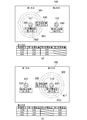
図6は、図5に示す配置例における、S421〜S425の処理の説明図である。図6(a)の上段に示すように、S422において1W下げる度に、給電領域301は、601、602と、より狭い範囲に変化する。図6(a)の下の表は、図5の配置例における、受電電力の変化例を示す図である。給電電力が10Wのとき、第1受電装置200、第2受電装置220の受電電力は、それぞれ3W、5Wである。給電電力が9W、8Wと下げられると、第1受電装置200の受電電力は、順に2W、0Wと低下し、第2受電装置220の受電電力は、順に4W、3Wと低下する。以上の処理により、第1方式の給電に関して、受電装置の受電電力が閾値以下となる給電電力を決定する。
FIG. 6 is an explanatory diagram of the processing of S421 to S425 in the arrangement example shown in FIG. As shown in the upper part of FIG. 6A, every
S425の処理の後、続いて第2方式の給電について同様に処理を進める。S426において、CPU121は、第2方式で給電可能な最大電力で給電するよう制御する。なお、S411で異物検知により、電力を下げている場合は、異物に対する損失が発生しない範囲での最大電力とする。次に、S427において、CPU121は、第2方式の給電電力を1W下げるように制御する。なお、受電アンテナの受電電力は、給電アンテナからの給電電力に比例する関係にあるため、第2方式の給電電力を下げると、第2方式における受電装置の第2方式による受電電力もこれに比例して低下する。
After the process of S425, the same process is performed for the second type of power supply. In step S426, the
次に、S428において、CPU121は、両方式に対応する受電装置の受電電力を確認する。図5の配置例では、CPU121は、第1受電装置200の受電電力を確認する。具体的には、CPU121は、第2通信アンテナ113を介して、両方式に対応する受電装置に受電電力の問い合わせを行い、両方式に対応する受電装置から受電電力の通知を受信する。CPU121は、両方式に対応する受電装置の受電電力が閾値以下と判断した場合には(S428でYes)、処理をS430へ進める。CPU121は、受電電力が閾値よりも大きいと判断した場合には(S428でNo)、処理をS429へ進める。なお、本実施形態においては、閾値を0Wとする。
Next, in S428, the
S429において、CPU121は、第2方式の給電電力を確認する。CPU121は、第2方式の給電電力が0Wであると判断した場合には(S429でYes)、処理をS430へ進める。S430において、CPU121は、第2方式による給電を停止するよう制御する。CPU121は、給電電力が0Wでない、すなわち0Wよりも大きいと判断した場合には(S429でNo)、処理をS427へ進める。すなわち、この場合、CPU121は、第2方式の給電電力を下げ、受電電力を確認する処理フローを、受電装置が受電する電力が閾値以下になるか、給電電力が0Wになるまで繰り返す。
In S429, the
なお、本実施形態においては、S428及びS429において、受電電力の閾値を0Wとしているが、閾値は実施形態に限定されるものではない。他の例としては、受電装置の最も消費電力の少ない動作モードの電力を閾値としてもよい。また、S423とS428の閾値は同じ値であってもよく、異なる値であってもよい。 In this embodiment, the threshold of received power is 0 W in S428 and S429, but the threshold is not limited to the embodiment. As another example, the power in the operation mode with the least power consumption of the power receiving apparatus may be used as the threshold value. Further, the threshold values of S423 and S428 may be the same value or different values.
図6(b)上に示すように、S427において1W下げる度に、給電領域302は、611、612と狭い範囲に変化する。図6(b)の下の表は、図5の配置例における、受電電力の変化例を示す図である。給電電力が10Wのとき、第1受電装置200、第3受電装置240の受電電力は、それぞれ2W、4Wである。給電電力が9W、8Wと下げられると、第1受電装置200の受電電力は、順に1W、0Wと低下し、第3受電装置240の受電電力は、順に、3W、2Wと低下する。以上の処理により、第2方式の給電に関して、受電装置の受電電力が閾値以下となる給電電力を決定する。
As shown in FIG. 6B, every time 1 S is lowered in S427, the
ここまでの処理により、両方式に対応する受電装置への給電について、各方式での受電電力が閾値以下となる給電電力が決定された。続いて、S430の後、CPU121は、処理を図4Bに示すS441へ進める。S441において、CPU121は、第1領域301及び第2領域302に存在する受電装置の検知結果に基づいて、第1方式及び第2方式の給電電力を下げることができるか否かを判定する(判定処理)。この処理を行う理由は以下のとおりである。すなわち、第1方式及び第2方式の両方式に対応する受電装置が存在するため、何れかの方式の給電電力を下げる必要がある。しかしながら、給電電力を下げることにより、第1方式又は第2方式により受電可能な受電装置への給電が行われなくなることは避けたい。そこで、CPU121は、まず第1の方式の給電電力を、両方式に対応する受電装置の受電電力が0Wとなる値に下げた場合でも、第1方式に対応する受電装置が受電可能であるか否かを判断する。そして、受電可能であると判断した場合に、第1の方式の給電電力を下げることができると判断する。
Through the processing up to this point, the power supply power at which the received power in each method is equal to or less than the threshold is determined for the power supply to the power receiving apparatus corresponding to both methods. Subsequently, after S430, the
具体的には、CPU121は、まず、第1方式の給電電力を、両方式に対応する受電装置の受電電力が0Wとなる値に下げた場合に、第1方式に対応する受電装置の受電電力が閾値以上となるか否かを確認する。このとき、CPU121は、S423、S424における処理結果を参照する。また、閾値は、本実施形態においては0Wとするが、閾値は任意の値であればよく、実施形態に限定されるものではない。
Specifically, first, when the power supply power of the first method is lowered to a value at which the power reception power of the power reception device corresponding to both methods is 0 W, the
そして、CPU121は、第1方式の給電電力を、両方式に対応する受電装置の受電電力が0Wとなる値に下げた場合でも、第1方式に対応する受電装置の受電電力が閾値以上となれば、第1方式の受電装置が受電可能であると判断する。そして、CPU121は、第1方式の受電装置が受電可能であると判断した場合に、第1方式の給電電力を下げることができると判断する。
Then, even when the power supply power of the first method is lowered to a value at which the power reception power of the power reception device corresponding to both methods is 0 W, the
同様に、CPU121は、第2の方式の給電電力を、両方式に対応する受電装置の受電電力が0Wとなる値に下げた場合でも、第2方式に対応する受電装置が受電可能である場合に、第2方式の給電電力を下げることができると判断する。具体的には、CPU121は、まず、第2方式の給電電力を、両方式に対応する受電装置の受電電力が0Wとなる値に下げた場合に、第2方式に対応する受電装置の受電電力が閾値以上となるか否かを確認する。このとき、CPU121は、S428、S429における処理結果を参照する。また、閾値は、本実施形態においては0Wとするが、閾値は任意の値であればよく、実施形態に限定されるものではない。
Similarly, when the power supply power of the second method is reduced to a value at which the power reception power of the power receiving device corresponding to both methods is reduced to 0 W, the
そして、CPU121は、第2方式の給電電力を、両方式に対応する受電装置の受電電力が0Wとなる値に下げた場合でも、第2方式に対応する受電装置の受電電力が閾値以上となれば、第2方式の受電装置が受電可能であると判断する。そして、CPU121は、第2方式の受電装置が受電可能であると判断した場合に、第2方式の給電電力を下げることができると判断する。
Then, even when the power supply power of the second method is lowered to a value at which the power reception power of the power reception device corresponding to both methods is 0 W, the power reception power of the power reception device corresponding to the second method cannot exceed the threshold. In this case, it is determined that the second type power receiving apparatus can receive power. Then, when the
CPU121は、両方式の給電電力を下げることができると判断した場合には(S442でYes)、処理をS445へ進める。CPU121は、第1方式の給電電力のみ下げられると判断した場合には(S442でNo,S443でYes)、処理をS457へ進める。CPU121は、第2方式の給電電力のみ下げられると判断した場合には(S442でNo,S443でNo)、処理をS459へ進める。CPU121は、第1方式及び第2方式いずれの給電電力も下げられないと判断した場合には(S442でNo,S443でNo,S444でNo)、各受電装置に対して安全に給電を行うことはできない。そのため、この場合は、第1方式及び第2方式の両方式の給電を停止し、給電制御処理を終了する。
If the
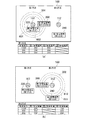
例えば、図6に示す配置例では、第1受電装置200の第1方式の受電電力が0Wとなるまで、第1方式の給電電力を下げた場合に、第2受電装置220の第1方式の受電電力は3Wであるため、第1方式の給電電力は下げられると判断される。また、第1受電装置200の第1方式の受電電力が0Wとなるまで給電電力を下げた場合に、第3受電装置240の受電電力は2Wであるため、第2方式の給電電力も下げられると判断される。
For example, in the arrangement example illustrated in FIG. 6, when the power supply power of the first method is lowered until the received power of the first method of the first
また、図7に示す配置例では、第1受電装置200の第1方式の受電電力が0Wとなるまで第1方式の給電電力を下げた場合に、第2受電装置220の第1方式の受電電力は3Wであるため、第1方式の給電電力は下げられると判断される。一方で、第1受電装置200の第2方式の受電電力が0Wとなるまで給電電力を下げた場合に、第3受電装置240の受電電力は0Wとなってしまうため、第2方式の受電電療は下げられないと判断される。
Further, in the arrangement example shown in FIG. 7, when the power supply power of the first method is lowered until the power reception power of the first method of the first
また、図8に示す配置例では、第1受電装置200の第1方式の受電電力が0Wとなるまで第1方式の給電電力を下げた場合に、第2受電装置220の受電電力は0Wとなってしまうため、第1方式の給電電力は下げられないと判断される。一方で、第1受電装置200の第2方式の受電電力が0Wとなるまで給電電力を下げた場合に、第3受電装置240の受電電力は2Wであるため、第2方式の給電電力は下げられると判断される。
Further, in the arrangement example illustrated in FIG. 8, when the power supplied by the first method is lowered until the power received by the first method of the first
第1方式の給電電力及び第2方式の給電電力のいずれも下げられないと判断されるのは、例えば図9に示すような配置例である。すなわち、第1受電装置200が第3領域303と重ならない第1領域301から、第3領域303と重ならない第2領域302に跨って配置されているような場合である。
For example, an arrangement example as shown in FIG. 9 determines that neither the first-type power supply power nor the second-type power supply power can be reduced. In other words, the first
S445において、CPU121は、第1方式で給電可能な最大電力で給電するよう制御する。本処理は、S421における処理と同様である。次に、S446において、CPU121は、両方式に対応する受電装置の受電電力を確認する。具体的には、CPU121は、第1通信アンテナ108を介して、両方式に対応する受電装置に受電電力の問い合わせを行い、両方式に対応する受電装置から受電電力の通知を受信する。次に、S447において、CPU121は、第1方式による給電を停止するよう制御する。
In S445, the
次に、S448において、CPU121は、第2方式で給電可能な最大電力で給電するよう制御する。本処理は、S426における処理と同様である。次に、S449において、CPU121は、両方式に対応する受電装置の受電電力を確認する。具体的には、CPU121は、第2通信アンテナ113を介して、両方式に対応する受電装置に受電電力の問い合わせを行い、両方式に対応する受電装置から受電電力の通知を受信する。次に、S450において、CPU121は、第2方式による給電を停止するよう制御する。
Next, in S <b> 448, the
次に、S451において、CPU121は、両方式に対応する受電装置の第1方式の受電電力と第2方式の受電電力を比較する。なお、第1方式の受電電力は、S446において受信した値であり、第2方式の受電電力は、S449において受信した値である。次に、S452において、CPU121は、S451における比較結果に基づいて、制限対象とする給電方式を決定する。CPU121は、第1方式の受電電力が大きい場合には、第2方式の給電を制限すると判断し、第2方式の受電電力が大きい場合には、第1方式の給電を制限すると判断する。
Next, in S451, the
CPU121は、第1方式の給電電力を制限すると判断した場合には(S452で第1方式)、処理をS453へ進める。CPU121は、第2方式の給電電力を制限すると判断した場合には(S452で第2方式)、処理をS455へ進める。例えば、図6の例では、第1方式における第1受電装置200の受電電力は3Wで、第2方式における第1受電装置200の受電電力は2Wである。このケースにおいては、第1方式の受電電力が大きいため、制限対象は、第2方式と判断される。
If the
S453において、CPU121は、第2方式の給電電力を、第1受電装置200の第2方式による受電電力が0Wとなるような給電電力まで下げるよう制御する。次に、S454において、CPU121は、第1方式の給電電力については、第1方式で給電可能な最大電力で給電するよう制御する。なお、本処理は、S421における処理と同様である。以上で、給電処理が終了する。なお、S453の処理とS454の処理の処理順は実施形態に限定されるものではない。他の例としては、S453の処理とS454の処理は並列に行われてもよく、また他の例としては、S454の処理の後にS453の処理が行われてもよい。また、S454における給電は、受電装置への給電可能な電力であればよく、必ずしも最大電力である必要はない。
In step S453, the
また、S455において、CPU121は、第1方式の給電電力を、第1受電装置の第1方式による受電電力が0Wとなるような給電電力まで下げるよう制御する。次に、S456において、CPU121は、第2方式の給電電力については、第2方式で給電可能な最大電力で給電するよう制御する。本処理は、S426における処理と同様である。以上で、給電処理が終了する。なお、S455の処理とS456の処理の処理順は実施形態に限定されるものではない。また、S456における給電は、受電装置への給電可能な電力であればよく、必ずしも最大電力である必要はない。
In step S455, the
また、S457及びS458においては、CPU121は、第1方式の給電電力を制限する処理を行う。S457及びS458の処理は、それぞれS455及びS456の処理と同様である。S459及びS460においては、CPU121は、第2方式の給電電力を制限する処理を行う。S459及びS460の処理は、それぞれS453及びS454の処理と同様である。ここで、S442〜S460の処理は、判定結果に基づいて、給電電力を制限する電力制御処理の一例である。
In S457 and S458, the
以上のように、本実施形態に係る給電装置100は、複数の方式の給電エリアが重なるように給電アンテナが配置されることで、装置を小型化することができる。さらに、給電装置100は、複数の方式それぞれに対応する受電装置以外の他の受電装置への給電の制限を少なくしつつ、複数の方式それぞれに対応する受電装置への給電を適切に行うことができる。
As described above, the
以上、本発明の好ましい実施形態について詳述したが、本発明は係る特定の実施形態に限定されるものではなく、特許請求の範囲に記載された本発明の要旨の範囲内において、種々の変形・変更が可能である。例えば、給電方式を3方式以上としてもよく、また通信と給電を1つのアンテナで行ってもよい。 The preferred embodiments of the present invention have been described in detail above, but the present invention is not limited to such specific embodiments, and various modifications can be made within the scope of the gist of the present invention described in the claims.・ Change is possible. For example, the power feeding method may be three or more, and communication and power feeding may be performed with one antenna.
(その他の実施例)
本発明は、上述の実施形態の1以上の機能を実現するプログラムを、ネットワーク又は記憶媒体を介してシステム又は装置に供給し、そのシステム又は装置のコンピュータにおける1つ以上のプロセッサーがプログラムを読出し実行する処理でも実現可能である。また、1以上の機能を実現する回路(例えば、ASIC)によっても実現可能である。
(Other examples)
The present invention supplies a program that realizes one or more functions of the above-described embodiments to a system or apparatus via a network or a storage medium, and one or more processors in a computer of the system or apparatus read and execute the program This process can be realized. It can also be realized by a circuit (for example, ASIC) that realizes one or more functions.
100 給電装置
200 第1受電装置
220 第2受電装置
240 第3受電装置
100
Claims (9)
第2の方式により給電を行う第2の給電手段と、
前記第1の方式及び前記第2の方式のうち少なくとも一方の方式で受電可能な受電装置が、受電可能な領域に存在することを検知する検知手段と、
前記第1の方式及び前記第2の方式のいずれの方式でも受電可能な第1の受電装置が、前記第1の方式及び前記第2の方式のいずれの方式でも受電可能な第1の領域に存在することが検知された場合に、前記検知手段による、前記第1の方式及び前記第2の方式のいずれか一方で受電可能な領域における、受電装置の検知結果に基づいて、前記第1の方式及び前記第2の方式のうち何れか一方の方式による給電電力を制限する電力制御手段と
を有することを特徴とする給電装置。 First power supply means for supplying power by the first method;
A second power supply means for supplying power by the second method;
Detecting means for detecting that a power receiving device capable of receiving power in at least one of the first method and the second method exists in a region where power can be received;
The first power receiving apparatus capable of receiving power in any of the first method and the second method is in the first region capable of receiving power in any of the first method and the second method. When the presence is detected, based on the detection result of the power receiving device in the region where power can be received by either the first method or the second method by the detecting means, And a power control means for limiting power supply according to any one of the system and the second system.
前記電力制御手段は、前記第1の受電装置が、前記第1の領域に存在することが検知された場合において、さらに前記第2の受電装置が前記第2の領域に存在し、かつ前記第3の受電装置が前記第3の領域に存在することが検知された場合に、前記判定手段による判定結果に基づいて、何れか一方の方式による給電電力を制限することを特徴とする請求項1に記載の給電装置。 When it is detected that the first power receiving device exists in the first area, a second power receiving device that can receive power by the first method can receive power by the first method. It is detected that the third power receiving device is present in the second area and the third power receiving device capable of receiving power by the second method is present in the third area capable of receiving power by the second method. In this case, can the second power receiving device be able to receive power at the first power supply power in which the first power received by the first method of the first power receiving device is equal to or less than a first threshold? Whether the second power received by the second method of the first power receiving device is equal to or lower than a second threshold value, and the third power receiving device It further has a determination means for determining whether or not power can be received,
In the case where it is detected that the first power receiving device exists in the first region, the power control means further includes the second power receiving device in the second region, and 2. When the presence of the third power receiving device is detected in the third region, the power supplied by any one of the methods is limited based on the determination result by the determination unit. The electric power feeder as described in.
前記電力制御手段は、前記第2の受電装置及び前記第3の受電装置いずれの装置においても受電可能と判定された場合に、前記比較手段による比較結果に基づいて、給電電力を制限する方式を決定することを特徴とする請求項4又は5に記載の給電装置。 Comparing means for comparing the received power in the first method of the first power receiving device with the received power in the second method of the first power receiving device when the power supply power is not limited In addition,
The power control unit is configured to limit the power supply based on a comparison result by the comparison unit when it is determined that power can be received by any of the second power receiving device and the third power receiving device. The power feeding device according to claim 4 or 5, wherein the power feeding device is determined.
第1の方式により給電を行う第1の給電ステップと、
第2の方式により給電を行う第2の給電ステップと、
前記第1の方式及び前記第2の方式のうち少なくとも一方の方式で受電可能な受電装置が、受電可能な領域に存在することを検知する検知ステップと、
前記第1の方式及び前記第2の方式のいずれの方式でも受電可能な第1の受電装置が、前記第1の方式及び前記第2の方式のいずれの方式でも受電可能な第1の領域に存在することが検知された場合に、前記検知ステップにおける、前記第1の方式及び前記第2の方式のいずれか一方で受電可能な領域における、受電装置の検知結果に基づいて、前記第1の方式及び前記第2の方式のうち何れか一方の方式による給電電力を制限する電力制御ステップと
を含むことを特徴とする給電制御方法。 A power supply control method executed by the power supply apparatus,
A first power supply step of supplying power by the first method;
A second power supply step for supplying power by the second method;
A detection step of detecting that a power receiving device capable of receiving power in at least one of the first method and the second method exists in a region where power can be received;
The first power receiving apparatus capable of receiving power in any of the first method and the second method is in the first region capable of receiving power in any of the first method and the second method. When the presence is detected, based on the detection result of the power receiving device in a region where power can be received by either the first method or the second method in the detection step, the first And a power control step of limiting power supply according to any one of the method and the second method.
第1の方式により給電を行うよう制御する第1の給電制御手段と、
第2の方式により給電を行うよう制御する第2の給電制御手段と、
前記第1の方式及び前記第2の方式のうち少なくとも一方の方式で受電可能な受電装置が、受電可能な領域に存在することを検知する検知手段と、
前記第1の方式及び前記第2の方式のいずれの方式でも受電可能な第1の受電装置が、前記第1の方式及び前記第2の方式のいずれの方式でも受電可能な第1の領域に存在することが検知された場合に、前記検知手段による、前記第1の方式及び前記第2の方式のいずれか一方で受電可能な領域における、受電装置の検知結果に基づいて、前記第1の方式及び前記第2の方式のうち何れか一方の方式による給電電力を制限する電力制御手段と
して機能させるためのプログラム。 Computer
First power supply control means for controlling power supply by the first method;
Second power supply control means for controlling power supply by the second method;
Detecting means for detecting that a power receiving device capable of receiving power in at least one of the first method and the second method exists in a region where power can be received;
The first power receiving apparatus capable of receiving power in any of the first method and the second method is in the first region capable of receiving power in any of the first method and the second method. When the presence is detected, based on the detection result of the power receiving device in the region where power can be received by either the first method or the second method by the detecting means, A program for functioning as power control means for limiting power supply by either one of the method and the second method.
Priority Applications (1)
| Application Number | Priority Date | Filing Date | Title |
|---|---|---|---|
| JP2016001249A JP2017123722A (en) | 2016-01-06 | 2016-01-06 | Power supply apparatus, power supply control method, and program |
Applications Claiming Priority (1)
| Application Number | Priority Date | Filing Date | Title |
|---|---|---|---|
| JP2016001249A JP2017123722A (en) | 2016-01-06 | 2016-01-06 | Power supply apparatus, power supply control method, and program |
Publications (1)
| Publication Number | Publication Date |
|---|---|
| JP2017123722A true JP2017123722A (en) | 2017-07-13 |
Family
ID=59306010
Family Applications (1)
| Application Number | Title | Priority Date | Filing Date |
|---|---|---|---|
| JP2016001249A Pending JP2017123722A (en) | 2016-01-06 | 2016-01-06 | Power supply apparatus, power supply control method, and program |
Country Status (1)
| Country | Link |
|---|---|
| JP (1) | JP2017123722A (en) |
Cited By (2)
| Publication number | Priority date | Publication date | Assignee | Title |
|---|---|---|---|---|
| JP2019208313A (en) * | 2018-05-29 | 2019-12-05 | ローム株式会社 | Wireless power transmission device, control circuit thereof, and wireless charging device |
| WO2022102496A1 (en) * | 2020-11-12 | 2022-05-19 | キヤノン株式会社 | Power transmission device, power transmission device control method, and program |
-
2016
- 2016-01-06 JP JP2016001249A patent/JP2017123722A/en active Pending
Cited By (3)
| Publication number | Priority date | Publication date | Assignee | Title |
|---|---|---|---|---|
| JP2019208313A (en) * | 2018-05-29 | 2019-12-05 | ローム株式会社 | Wireless power transmission device, control circuit thereof, and wireless charging device |
| JP7144192B2 (en) | 2018-05-29 | 2022-09-29 | ローム株式会社 | Wireless power transmission device and its control circuit |
| WO2022102496A1 (en) * | 2020-11-12 | 2022-05-19 | キヤノン株式会社 | Power transmission device, power transmission device control method, and program |
Similar Documents
| Publication | Publication Date | Title |
|---|---|---|
| US10797530B2 (en) | Power transmitting method and power transmitter for communication with power receiver | |
| EP3180834B1 (en) | Method for determining cross connection in wireless charging | |
| TWI860319B (en) | Wireless power transmission using multiple transmitters and receivers | |
| CN106233569B (en) | Ways to Prevent Abnormalities During Wireless Charging | |
| EP2710707B1 (en) | Power transmitting method and power transmitter for communication with power receiver | |
| EP4024663B1 (en) | Wireless charging apparatus, device to be charged, charging system and method, and storage medium | |
| CN106030966B (en) | Method for detecting load in wireless charging | |
| CN105745815A (en) | Method for allocating wireless charging power for multiple wireless power receivers | |
| CN103609035A (en) | Method of performing bidirectional communication between transmitter and receiver in wireless power transmission/reception system, the transmitter, and the receiver | |
| KR20170021011A (en) | Wireless Power Transmitter And Vehicle Control Unit Connected To The Same | |
| JP2009251895A (en) | Power exchange device, power exchange method, program, and power exchange system | |
| CN105144545A (en) | Wireless power transmitting device and method for same | |
| US10979101B2 (en) | Power feeding device and power feeding method | |
| US11011932B2 (en) | Mouse pad comprising wireless power transmission apparatus and mouse | |
| KR20220008916A (en) | Wireless power transmitter with multiple primary and adjacent coil muting capabilities | |
| CN110957770A (en) | Wireless charging method and system and computer readable storage medium | |
| US20160105032A1 (en) | Wireless power reception device and electronic device including the same | |
| US20220302760A1 (en) | A power transfer apparatus and method therefor | |
| US9973029B2 (en) | Wireless power transmission/reception apparatus | |
| JP2017123722A (en) | Power supply apparatus, power supply control method, and program | |
| JP2015130748A (en) | Power receiving device, power transmitting / receiving device, power transmitting device, wireless power feeding system, information processing method, and program | |
| CN114365380A (en) | Wireless power transfer device with multiple controllers and adjacent coil shielding | |
| CN105990886B (en) | Non-contact electric power sending device, power receiving apparatus and electric power receive-transmit system | |
| CN107112810A (en) | Wireless power transmitting device and wireless charging system including wireless power transmitting device | |
| JP2025148030A (en) | Wireless power receiving device, wireless power supply system, and wireless power receiving method |