KR20170021011A - Wireless Power Transmitter And Vehicle Control Unit Connected To The Same - Google Patents
Wireless Power Transmitter And Vehicle Control Unit Connected To The Same Download PDFInfo
- Publication number
- KR20170021011A KR20170021011A KR1020150115255A KR20150115255A KR20170021011A KR 20170021011 A KR20170021011 A KR 20170021011A KR 1020150115255 A KR1020150115255 A KR 1020150115255A KR 20150115255 A KR20150115255 A KR 20150115255A KR 20170021011 A KR20170021011 A KR 20170021011A
- Authority
- KR
- South Korea
- Prior art keywords
- information
- wireless power
- wireless
- state
- charging
- Prior art date
Links
- 230000006854 communication Effects 0.000 claims description 125
- 238000004891 communication Methods 0.000 claims description 125
- 230000005540 biological transmission Effects 0.000 claims description 109
- 238000000034 method Methods 0.000 claims description 79
- 238000001514 detection method Methods 0.000 claims description 68
- 230000002159 abnormal effect Effects 0.000 claims description 38
- 230000008859 change Effects 0.000 claims description 30
- 238000012937 correction Methods 0.000 claims description 12
- 238000001816 cooling Methods 0.000 claims description 11
- 238000005516 engineering process Methods 0.000 abstract description 13
- 230000007704 transition Effects 0.000 description 53
- 238000010586 diagram Methods 0.000 description 22
- 230000005674 electromagnetic induction Effects 0.000 description 22
- 238000009774 resonance method Methods 0.000 description 17
- 238000012546 transfer Methods 0.000 description 17
- 230000006870 function Effects 0.000 description 13
- 238000006243 chemical reaction Methods 0.000 description 7
- 239000000126 substance Substances 0.000 description 7
- 230000004044 response Effects 0.000 description 6
- 238000013021 overheating Methods 0.000 description 5
- 230000007175 bidirectional communication Effects 0.000 description 4
- 238000012790 confirmation Methods 0.000 description 4
- 238000004590 computer program Methods 0.000 description 3
- 239000000470 constituent Substances 0.000 description 3
- 230000000694 effects Effects 0.000 description 3
- 238000012544 monitoring process Methods 0.000 description 3
- 230000000903 blocking effect Effects 0.000 description 2
- 238000004364 calculation method Methods 0.000 description 2
- 230000005672 electromagnetic field Effects 0.000 description 2
- 230000003287 optical effect Effects 0.000 description 2
- 230000008901 benefit Effects 0.000 description 1
- 239000003990 capacitor Substances 0.000 description 1
- 239000004020 conductor Substances 0.000 description 1
- 230000008878 coupling Effects 0.000 description 1
- 238000010168 coupling process Methods 0.000 description 1
- 238000005859 coupling reaction Methods 0.000 description 1
- 238000013500 data storage Methods 0.000 description 1
- 230000009849 deactivation Effects 0.000 description 1
- 230000003247 decreasing effect Effects 0.000 description 1
- 238000007599 discharging Methods 0.000 description 1
- 230000005684 electric field Effects 0.000 description 1
- 230000005611 electricity Effects 0.000 description 1
- 210000003195 fascia Anatomy 0.000 description 1
- 230000004907 flux Effects 0.000 description 1
- 230000006698 induction Effects 0.000 description 1
- 230000000977 initiatory effect Effects 0.000 description 1
- 238000004519 manufacturing process Methods 0.000 description 1
- 230000008520 organization Effects 0.000 description 1
- 230000001151 other effect Effects 0.000 description 1
- 230000003071 parasitic effect Effects 0.000 description 1
Images


Classifications
-
- H—ELECTRICITY
- H05—ELECTRIC TECHNIQUES NOT OTHERWISE PROVIDED FOR
- H05K—PRINTED CIRCUITS; CASINGS OR CONSTRUCTIONAL DETAILS OF ELECTRIC APPARATUS; MANUFACTURE OF ASSEMBLAGES OF ELECTRICAL COMPONENTS
- H05K7/00—Constructional details common to different types of electric apparatus
- H05K7/20—Modifications to facilitate cooling, ventilating, or heating
-
- H—ELECTRICITY
- H02—GENERATION; CONVERSION OR DISTRIBUTION OF ELECTRIC POWER
- H02J—CIRCUIT ARRANGEMENTS OR SYSTEMS FOR SUPPLYING OR DISTRIBUTING ELECTRIC POWER; SYSTEMS FOR STORING ELECTRIC ENERGY
- H02J50/00—Circuit arrangements or systems for wireless supply or distribution of electric power
- H02J50/10—Circuit arrangements or systems for wireless supply or distribution of electric power using inductive coupling
- H02J50/12—Circuit arrangements or systems for wireless supply or distribution of electric power using inductive coupling of the resonant type
-
- H02J7/025—
-
- H02J17/00—
-
- H—ELECTRICITY
- H02—GENERATION; CONVERSION OR DISTRIBUTION OF ELECTRIC POWER
- H02J—CIRCUIT ARRANGEMENTS OR SYSTEMS FOR SUPPLYING OR DISTRIBUTING ELECTRIC POWER; SYSTEMS FOR STORING ELECTRIC ENERGY
- H02J50/00—Circuit arrangements or systems for wireless supply or distribution of electric power
- H02J50/80—Circuit arrangements or systems for wireless supply or distribution of electric power involving the exchange of data, concerning supply or distribution of electric power, between transmitting devices and receiving devices
-
- H—ELECTRICITY
- H02—GENERATION; CONVERSION OR DISTRIBUTION OF ELECTRIC POWER
- H02J—CIRCUIT ARRANGEMENTS OR SYSTEMS FOR SUPPLYING OR DISTRIBUTING ELECTRIC POWER; SYSTEMS FOR STORING ELECTRIC ENERGY
- H02J7/00—Circuit arrangements for charging or depolarising batteries or for supplying loads from batteries
- H02J7/0047—Circuit arrangements for charging or depolarising batteries or for supplying loads from batteries with monitoring or indicating devices or circuits
-
- H—ELECTRICITY
- H05—ELECTRIC TECHNIQUES NOT OTHERWISE PROVIDED FOR
- H05K—PRINTED CIRCUITS; CASINGS OR CONSTRUCTIONAL DETAILS OF ELECTRIC APPARATUS; MANUFACTURE OF ASSEMBLAGES OF ELECTRICAL COMPONENTS
- H05K7/00—Constructional details common to different types of electric apparatus
- H05K7/20—Modifications to facilitate cooling, ventilating, or heating
- H05K7/20845—Modifications to facilitate cooling, ventilating, or heating for automotive electronic casings
-
- H02J2007/005—
-
- H—ELECTRICITY
- H02—GENERATION; CONVERSION OR DISTRIBUTION OF ELECTRIC POWER
- H02J—CIRCUIT ARRANGEMENTS OR SYSTEMS FOR SUPPLYING OR DISTRIBUTING ELECTRIC POWER; SYSTEMS FOR STORING ELECTRIC ENERGY
- H02J9/00—Circuit arrangements for emergency or stand-by power supply, e.g. for emergency lighting
- H02J9/005—Circuit arrangements for emergency or stand-by power supply, e.g. for emergency lighting using a power saving mode
Abstract
Description
본 발명은 무선 충전 기술에 관한 것으로서, 상세하게, 차량 내부에서 무선 충전 동작 수행 시 차량 자체의 시스템을 이용해 상기 무선 충전 동작에 대한 정보를 확인할 수 있는 무선 전력 송신기 및 이와 연결되는 차량 제어 유닛에 관한 것이다.The present invention relates to a wireless charging technique, and more particularly, to a wireless power transmitter capable of confirming information on the wireless charging operation using a system of the vehicle itself when performing a wireless charging operation in a vehicle, and a vehicle control unit will be.
최근 정보 통신 기술이 급속도로 발전함에 따라, 정보 통신 기술을 기반으로 하는 유비쿼터스 사회가 이루어지고 있다.Recently, as the information and communication technology rapidly develops, a ubiquitous society based on information and communication technology is being made.
언제 어디서나 정보통신 기기들이 접속되기 위해서는 사회 모든 시설에 통신 기능을 가진 컴퓨터 칩을 내장시킨 센서들이 설치되어야 한다. 따라서 이들 기기나 센서의 전원 공급 문제는 새로운 과제가 되고 있다. 또한 휴대폰뿐만 아니라 블루투스 핸드셋과 아이팟 같은 뮤직 플레이어 등의 휴대기기 종류가 급격히 늘어나면서 배터리를 충전하는 작업이 사용자에게 시간과 수고를 요구하고 됐다. 이러한 문제를 해결하는 방법으로 무선 전력 전송 기술이 최근 들어 관심을 받고 있다.In order for information communication devices to be connected anytime and anywhere, sensors equipped with a computer chip having a communication function must be installed in all facilities of the society. Therefore, power supply problems of these devices and sensors are becoming a new challenge. In addition, mobile devices such as Bluetooth handsets and iPods, as well as mobile phones, have been rapidly increasing in number, and charging the battery has required users time and effort. As a way to solve this problem, wireless power transmission technology has recently attracted attention.
무선 전력 전송 기술(wireless power transmission 또는 wireless energy transfer)은 자기장의 유도 원리를 이용하여 무선으로 송신기에서 수신기로 전기 에너지를 전송하는 기술로서, 이미 1800년대에 전자기유도 원리를 이용한 전기 모터나 변압기가 사용되기 시작했고, 그 후로는 라디오파나 레이저와 같은 전자파를 방사해서 전기에너지를 전송하는 방법도 시도되었다. 우리가 흔히 사용하는 전동칫솔이나 일부 무선면도기도 실상은 전자기유도 원리로 충전된다.The wireless power transmission technology (wireless power transmission or wireless energy transfer) is a technology to transmit electric energy from the transmitter to the receiver wirelessly using the induction principle of the magnetic field. In the 1800s, electric motor or transformer Thereafter, a method of transmitting electric energy by radiating an electromagnetic wave such as a radio wave or a laser was tried. Our electric toothbrushes and some wireless shavers are actually charged with electromagnetic induction.
현재까지 무선을 이용한 에너지 전달 방식은 크게 전자기 유도 방식, 자기 공진(Electromagnetic Resonance) 방식 및 단파장 무선 주파수를 이용한 RF 전송 방식 등으로 구분될 수 있다.Until now, energy transmission using radio has been classified into electromagnetic induction, magnetic resonance, and RF transmission using short wavelength radio frequency.
전자기 유도 방식은 두 개의 코일을 서로 인접시킨 후 한 개의 코일에 전류를 흘려보내면 이 때 발생한 자속(MagneticFlux)이 다른 코일에 기전력을 일으키는 현상을 사용한 기술로서, 휴대폰과 같은 소형기기를 중심으로 빠르게 상용화가 진행되고 있다. 전자기 유도 방식은 최대 수백 키로와트(kW)의 전력을 전송할 수 있고 효율도 높지만 최대 전송 거리가 1센티미터(cm) 이하이므로 일반적으로 충전기나 바닥에 인접시켜야 하는 단점이 있다.In the electromagnetic induction method, when two coils are adjacent to each other and a current is supplied to one coil, a magnetic flux generated at this time causes an electromotive force to the other coils. This technique is rapidly commercialized centering on small- . Electromagnetic induction has the disadvantage of being able to transmit power of up to several hundred kilowatts (kW) and high efficiency, but the maximum transmission distance is less than 1 centimeter (cm), so it must be generally adjacent to the charger or floor.
전자기 공진 방식은 전자기파나 전류 등을 활용하는 대신 전기장이나 자기장을 이용하는 특징이 있다. 전자기 공진 방식은 전자파 문제의 영향을 거의 받지 않으므로 다른 전자 기기나 인체에 안전하다는 장점이 있다. 반면, 한정된 거리와 공간에서만 활용할 수 있으며 에너지 전달 효율이 다소 낮다는 단점이 있다.The electromagnetic resonance method is characterized by using an electric field or a magnetic field instead of using an electromagnetic wave or a current. The electromagnetic resonance method is advantageous in that it is safe to other electronic devices and human body since it is hardly influenced by the electromagnetic wave problem. On the other hand, it can be used only at a limited distance and space, and has a disadvantage that energy transfer efficiency is somewhat low.
단파장 무선 전력 전송 방식-간단히, RF 전송 방식-은 에너지가 라디오 파(RadioWave)형태로 직접 송수신될 수 있다는 점을 활용한 것이다. 이 기술은 렉테나(rectenna)를 이용하는 RF 방식의 무선 전력 전송 방식으로서, 렉테나는 안테나(antenna)와 정류기(rectifier)의 합성어로서 RF 전력을 직접 직류 전력으로 변환하는 소자를 의미한다. 즉, RF 방식은 AC 라디오파를 DC로 변환하여 사용하는 기술로서, 최근 효율이 향상되면서 상용화에 대한 연구가 활발히 진행되고 있다.Short wavelength wireless power transmission - simply, RF transmission - takes advantage of the fact that energy can be transmitted and received directly in radio wave form. This technology is a RF power transmission system using a rectenna. Rectena is a combination of an antenna and a rectifier, which means a device that converts RF power directly into direct current power. That is, the RF method is a technique of converting an AC radio wave into DC and using it. Recently, as the efficiency has improved, commercialization has been actively researched.
무선 전력 전송 기술은 모바일 뿐만 아니라 IT, 철도, 가전 산업 등 산업 전반에 다양하게 활용될 수 있다.Wireless power transmission technology can be applied not only to mobile, but also to various industries such as IT, railroad, and household appliance industry.
또한, 차량 내부에서 무선 전력 전송 기술의 활용 가능성에 대한 관심이 높아지고 있으며, 무선 전력 전송 기술을 차량에 적용함에 있어서 차량 주행 환경의 특수성(예컨대, 차체 흔들림)이 고려되어야 하는 문제점이 있었다.In addition, there is a growing interest in the possibility of utilizing wireless power transmission technology in a vehicle, and there is a problem that the specificity of the vehicle traveling environment (for example, vehicle shake) must be taken into account when applying the wireless power transmission technology to a vehicle.
본 발명은 상술한 종래 기술의 문제점을 해결하기 위해 고안된 것으로, 본 발명의 목적은 무선 전력 송신기 및 이와 연결되는 차량 제어 유닛을 제공하는 것이다.It is an object of the present invention to provide a wireless power transmitter and a vehicle control unit connected to the wireless power transmitter.
본 발명의 다른 목적은 차량 주행 환경에서 발생되는 무선 충전 동작에 관련된 정보들을 사용자가 간편하게 확인할 수 있는 무선 전력 송신기 및 이와 연결되는 차량 제어 유닛을 제공하는 것이다.It is another object of the present invention to provide a wireless power transmitter and a vehicle control unit connected to the wireless power transmitter, in which a user can easily confirm information related to a wireless charging operation occurring in a vehicle driving environment.
본 발명의 또 다른 목적은 복수의 무선 전력 수신기들이 무선 충전 동작에 참여할 경우 이를 모니터링 및 제어할 수 있는 인터페이스를 제공할 수 있는 무선 전력 송신기 및 이와 연결되는 차량 제어 유닛을 제공하는 것이다.It is yet another object of the present invention to provide a wireless power transmitter capable of providing an interface for monitoring and controlling when a plurality of wireless power receivers participate in a wireless charging operation and a vehicle control unit connected thereto.
본 발명에서 이루고자 하는 기술적 과제들은 이상에서 언급한 기술적 과제들로 제한되지 않으며, 언급하지 않은 또 다른 기술적 과제들은 아래의 기재로부터 본 발명이 속하는 기술 분야에서 통상의 지식을 가진 자에게 명확하게 이해될 수 있을 것이다.It is to be understood that both the foregoing general description and the following detailed description are exemplary and explanatory and are not restrictive of the invention, unless further departing from the spirit and scope of the invention as defined by the appended claims. It will be possible.
본 발명의 일 실시예에 따른 차량 제어 유닛은 무선 충전 동작을 수행하는 무선 전력 송신기 및 무선 전력 수신기 중 적어도 하나에 연결되고, 상기 무선 충전 동작에 관련된 상태 감지 정보에 기초하여 생성되는 충전 상태 정보에 대응하는 메시지를 디스플레이할 수 있다.According to one embodiment of the present invention The vehicle control unit may be connected to at least one of a wireless power transmitter and a wireless power receiver performing a wireless charging operation and may display a message corresponding to charging status information generated based on status sensing information associated with the wireless charging operation .
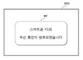
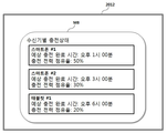
실시예에 따라, 상기 상태 감지 정보는 상기 무선 전력 수신기의 부하의 총 전력 용량, 잔여 전력 용량, 및 부하 수신 전력 정보를 포함하고, 상기 충전 상태 정보는 상기 총 전력 용량, 상기 잔여 전력 용량, 및 상기 부하 수신 전력 정보를 기초로 산출되는 상기 무선 전력 수신기의 충전이 완료되는 예상 시간에 대한 정보인 충전 완료 예상 시간 정보를 포함할 수 있다.According to an embodiment, the status detection information includes a total power capacity, a remaining power capacity and a load received power information of a load of the wireless power receiver, and the charging status information includes the total power capacity, the remaining power capacity, And estimated completion time information, which is information on an expected time at which the charging of the wireless power receiver is completed based on the load receiving power information.
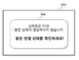
실시예에 따라, 상기 상태 감지 정보는 채널 설정을 위한 신호를 전송하여 피드백(feedback) 신호의 수신 여부에 대한 정보인 채널 설정 결과 정보 및 임피던스 변화를 포함하고, 상기 충전 상태 정보는 상기 임피던스 변화가 발생하였음에도 상기 채널 설정 결과 정보가 상기 피드백 신호를 수신하지 못함을 나타내는 이물질 감지 정보를 포함할 수 있다.According to an embodiment of the present invention, the state detection information includes a channel setting result information and an impedance change, which are information on whether or not a feedback signal is transmitted by transmitting a signal for setting a channel, The channel setting result information may include foreign substance detection information indicating that the feedback signal is not received.
실시예에 따라, 상기 상태 감지 정보는 상기 무선 전력 송신기의 송신 전력 정보, 및 상기 무선 전력 수신기의 현재 수신 전력 정보를 포함하고, 상기 충전 상태 정보는 상기 현재 수신 전력 정보와 상기 송신 전력 정보의 비율이 정상 범위를 벗어날 경우 생성되는 배열 보정 정보를 포함할 수 있다.According to an embodiment, the status sensing information includes transmission power information of the wireless power transmitter and current reception power information of the wireless power receiver, and the charging status information includes a ratio of the current reception power information to the transmission power information Lt; RTI ID = 0.0 > range. ≪ / RTI >
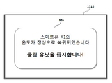
실시예에 따라, 상기 상태 감지 정보는 상기 무선 전력 송신기의 온도 정보를 포함하고, 상기 충전 상태 정보는 상기 온도 정보에 따른 상기 무선 전력 수신기의 온도가 정상 온도 범위를 벗어날 경우 생성되는 이상 온도 정보를 포함할 수 있다.According to an embodiment, the state detection information includes temperature information of the wireless power transmitter, and the charge state information includes abnormal temperature information generated when the temperature of the wireless power receiver according to the temperature information is out of the normal temperature range .
실시예에 따라, 상기 차량 제어 유닛은, 상기 이상 온도 정보가 수신될 경우 상기 이상 온도 정보에 따라 상기 무선 전력 수신기의 온도를 감소시키는 쿨링 유닛을 작동시킬 수 있다.According to the embodiment, the vehicle control unit may operate a cooling unit that reduces the temperature of the wireless power receiver according to the abnormal temperature information when the abnormal temperature information is received.
실시예에 따라, 상기 차량 제어 유닛은, 상기 무선 전력 수신기의 온도가 상기 정상 온도 범위 내로 복귀할 경우 상기 쿨링 유닛의 동작을 중지시킬 수 있다.According to an embodiment, the vehicle control unit may stop the operation of the cooling unit when the temperature of the wireless power receiver returns within the normal temperature range.
실시예에 따라, 상기 상태 감지 정보는 상기 무선 전력 송신기와 상기 무선 전력 수신기가 서로 연결되어 생성되는 충전 시작 정보를 포함하고, 상기 충전 상태 정보는 상기 충전 시작 정보 및 상기 무선 전력 수신기의 수신기 식별 정보에 기초하여 생성되는 충전 연결 정보를 포함할 수 있다.According to an embodiment, the state detection information includes charge start information generated by the wireless power transmitter and the wireless power receiver being connected to each other, and the charge state information includes charge start information and receiver identification information of the wireless power receiver Based on the charging connection information.
실시예에 따라, 상기 충전 상태 정보는 상기 무선 전력 수신기가 제공하는 상기 상태 감지 정보에 기초하여 상기 무선 전력 송신기에 의해 생성되어 상기 무선 전력 송신기로부터 수신될 수 있다.According to an embodiment, the state of charge information may be generated by the wireless power transmitter based on the state sensing information provided by the wireless power receiver and received from the wireless power transmitter.
실시예에 따라, 상기 충전 상태 정보는 상기 무선 전력 수신기로부터 수신되는 상기 상태 감지 정보에 기초하여 상기 차량 제어 유닛에 의해 생성될 수 있다.According to an embodiment, the charge status information may be generated by the vehicle control unit based on the status sense information received from the wireless power receiver.
실시예에 따라, 상기 충전 상태 정보는 상기 무선 전력 수신기에 의해 생성되어 수신될 수 있다.According to an embodiment, the charge state information may be generated and received by the wireless power receiver.
본 발명의 다른 실시예에 따른 차량 제어 유닛은 무선 충전 동작을 수행하는 무선 전력 송신기 및 복수의 무선 전력 수신기들 중 적어도 하나에 연결되고, 상기 무선 충전 동작에 관련된 상태 감지 정보에 기초하여 생성되는 충전 상태 정보에 대응하는 메시지를 디스플레이할 수 있다.The vehicle control unit according to another embodiment of the present invention A wireless power transmitter performing a wireless charging operation and a message connected to at least one of the plurality of wireless power receivers and corresponding to charging status information generated based on status sensing information associated with the wireless charging operation.
본 발명의 또 다른 실시예에 따른 차량 제어 유닛은 무선 충전 동작을 수행하는 무선 전력 송신기 및 무선 전력 수신기에 연결되고, 상기 무선 충전 동작에 관련된 상태 감지 정보에 기초하여 생성되는 충전 상태 정보에 대응하는 메시지를 디스플레이하며, 상기 무선 전력 수신기와 근거리 통신 방식으로 연결될 수 있다.A vehicle control unit according to another embodiment of the present invention includes a wireless power transmitter and a wireless power transmitter connected to a wireless power transmitter and performing wireless charging operation, Message, and may be coupled in a short-range communication manner with the wireless power receiver.
본 발명의 또 다른 실시예에 따른 차량 제어 유닛은 무선 충전 동작을 수행하는 무선 전력 송신기 및 복수의 무선 전력 수신기들 중 적어도 하나에 연결되고, 상기 무선 충전 동작에 관련된 상태 감지 정보에 기초하여 생성되는 충전 상태 정보에 대응하는 메시지를 디스플레이하며, 상기 무선 전력 수신기와 근거리 통신 방식으로 연결될 수 있다.A vehicle control unit according to another embodiment of the present invention is connected to at least one of a wireless power transmitter and a plurality of wireless power receivers for performing a wireless charging operation and is generated based on state sensing information related to the wireless charging operation And displays a message corresponding to the charging status information, and may be connected to the wireless power receiver in a short distance communication manner.
본 발명의 일 실시예에 따른 무선 전력 송신기는 무선 전력 수신기에 대해 수행하는 무선 충전 동작에 관련된 상태 감지 정보에 기초하여 충전 상태 정보를 생성하고, 상기 충전 상태 정보에 대응하는 메시지가 디스플레이되도록 차량 제어 유닛으로 상기 충전 상태 정보를 전송할 수 있다.The wireless power transmitter according to an exemplary embodiment of the present invention generates charge state information based on state detection information related to a wireless charge operation performed on a wireless power receiver and displays a message corresponding to the charge state information The charging state information can be transmitted to the unit.
상기 본 발명의 양태들은 본 발명의 바람직한 실시예들 중 일부에 불과하며, 본원 발명의 기술적 특징들이 반영된 다양한 실시예들이 당해 기술분야의 통상적인 지식을 가진 자에 의해 이하 상술할 본 발명의 상세한 설명을 기반으로 도출되고 이해될 수 있다.It is to be understood that both the foregoing general description and the following detailed description of the present invention are exemplary and explanatory and are intended to provide further explanation of the invention as claimed. And can be understood and understood.
본 발명에 따른 방법 및 장치에 대한 효과에 대해 설명하면 다음과 같다.Effects of the method and apparatus according to the present invention will be described as follows.
본 발명의 일 실시예에 따른 무선 충전 시스템에 의하면, 무선 충전 동작에 관련된 다양한 정보를 차량 제어 유닛을 통해 출력함으로써, 차량 주행 환경에서 발생할 수 있는 다양한 충전 상태 변화를 사용자가 보다 안전하고 신속하게 인지하고 대처할 수 있도록 하는 효과가 있다.According to the wireless charging system of the present invention, by outputting various information related to the wireless charging operation through the vehicle control unit, it is possible to recognize various charging state changes that may occur in the vehicle traveling environment more safely and promptly And to cope with the problem.
또한, 복수의 포터블 장치들을 충전하는 경우에도, 복수의 포터블 장치들의 무선 충전 상태를 모니터링 및 제어할 수 있는 효과가 있다.In addition, even when a plurality of portable devices are charged, the wireless charging state of a plurality of portable devices can be monitored and controlled.
아울러, 차량 제어 유닛과 무선 전력 수신기 사이의 직접 통신을 통해, 차량 제어 유닛에 보다 다양한 정보가 제공될 수 있도록 할 수 있다.In addition, through direct communication between the vehicle control unit and the wireless power receiver, it is possible to provide more various information to the vehicle control unit.
본 발명에서 얻을 수 있는 효과는 이상에서 언급한 효과들로 제한되지 않으며, 언급하지 않은 또 다른 효과들은 아래의 기재로부터 본 발명이 속하는 기술분야에서 통상의 지식을 가진 자에게 명확하게 이해될 수 있을 것이다.The effects obtained by the present invention are not limited to the above-mentioned effects, and other effects not mentioned can be clearly understood by those skilled in the art from the following description will be.
이하에 첨부되는 도면들은 본 발명에 관한 이해를 돕기 위한 것으로, 상세한 설명과 함께 본 발명에 대한 실시예들을 제공한다. 다만, 본 발명의 기술적 특징이 특정 도면에 한정되는 것은 아니며, 각 도면에서 개시하는 특징들은 서로 조합되어 새로운 실시예로 구성될 수 있다.
도 1은 본 발명의 일 실시예에 따른 전자기 공진 방식의 무선 전력 전송 방법을 설명하기 위한 시스템 구성도이다.
도 2는 본 발명의 일 실시예에 따른 전자기 공진 방식에서의 무선 전력 송신기의 타입 및 특성을 설명하기 위한 도면이다.
도 3은 본 발명의 일 실시예에 따른 전자기 공진 방식에서의 무선 전력 수신기의 타입 및 특성을 설명하기 위한 도면이다.
도 4는 본 발명의 일 실시예에 따른 전자기 공진 방식에서의 무선 전력 전송 시스템의 등가 회로도이다.
도 5는 본 발명의 일 실시예에 따른 전자기 공진 방식에서의 무선 전력 송신기 상태 천이 절차를 설명하기 위한 상태 천이도이다.
도 6은 본 발명의 일 실시예에 따른 전자기 공진 방식을 지원하는 무선 전력 수신기의 상태 천이도이다.
도 7은 본 발명의 일 실시예에 따른 전자기 공진 방식에 있어서의 VRECT에 따른 무선 전력 수신기의 동작 영역을 설명하기 위한 도면이다.
도 8은 본 발명의 일 실시예에 따른 전자기 유도 방식의 무선 충전 시스템을 설명하기 위한 도면이다.
도 9는 본 발명의 일 실시예에 따른 전자기 유도 방식을 지원하는 무선 전력 송신기의 상태 천이도이다.
도 10은 본 발명의 일 실시예에 따른 무선 충전 시스템의 구조를 설명하기 위한 블록도이다.
도 11은 도 10에 도시된 무선 전력 송신기가 차량 내부에 설치되는 위치를 설명하기 위한 도면이다.
도 12는 도 10에 도시된 무선 충전 시스템의 일 실시예를 나타낸 블록도이다.
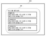
도 13 내지 도 19 각각은 디스플레이 유닛에 표시될 수 있는 메시지의 일 예를 나타낸 도면이다.
도 20은 도 10에 도시된 무선 충전 시스템의 다른 실시예를 나타낸 블록도이다.
도 21 내지 도 22 각각은 디스플레이 유닛에 표시될 수 있는 메시지의 일 예를 나타낸 도면이다.
도 23은 도 10에 도시된 무선 충전 시스템의 또 다른 실시예를 나타낸 블록도이다.
도 24 내지 도 25 각각은 디스플레이 유닛에 표시될 수 있는 메시지의 일 예를 나타낸 도면이다.BRIEF DESCRIPTION OF THE DRAWINGS The accompanying drawings, which are included to provide a further understanding of the invention and are incorporated in and constitute a part of this specification, illustrate embodiments of the invention and, together with the description, serve to explain the principles of the invention. It is to be understood, however, that the technical features of the present invention are not limited to the specific drawings, and the features disclosed in the drawings may be combined with each other to constitute a new embodiment.
FIG. 1 is a system configuration diagram for explaining a method of transmitting a wireless power of an electromagnetic resonance method according to an embodiment of the present invention.
2 is a view for explaining types and characteristics of a wireless power transmitter in an electromagnetic resonance method according to an embodiment of the present invention.
3 is a view for explaining types and characteristics of a wireless power receiver in an electromagnetic resonance method according to an embodiment of the present invention.
4 is an equivalent circuit diagram of a wireless power transmission system in an electromagnetic resonance system according to an embodiment of the present invention.
5 is a state transition diagram for explaining a state transition procedure of a wireless power transmitter in an electromagnetic resonance system according to an embodiment of the present invention.
6 is a state transition diagram of a wireless power receiver supporting an electromagnetic resonance method according to an embodiment of the present invention.
7 is a view for explaining an operation region of a wireless power receiver according to V RECT in the electromagnetic resonance method according to an embodiment of the present invention.
8 is a view for explaining a wireless charging system of an electromagnetic induction type according to an embodiment of the present invention.
9 is a state transition diagram of a wireless power transmitter supporting an electromagnetic induction method according to an embodiment of the present invention.
10 is a block diagram illustrating a structure of a wireless charging system according to an embodiment of the present invention.
11 is a view for explaining a position where the wireless power transmitter shown in FIG. 10 is installed in a vehicle.
12 is a block diagram showing an embodiment of the wireless charging system shown in FIG.
Each of Figs. 13 to 19 is a diagram showing an example of a message that can be displayed on the display unit.
20 is a block diagram showing another embodiment of the wireless charging system shown in FIG.
Each of Figs. 21 to 22 is a diagram showing an example of a message that can be displayed on the display unit.
Fig. 23 is a block diagram showing another embodiment of the wireless charging system shown in Fig. 10. Fig.
24 to 25 are views each showing an example of a message that can be displayed on the display unit.
이하, 본 발명의 실시예들이 적용되는 장치 및 다양한 방법들에 대하여 도면을 참조하여 보다 상세하게 설명한다. 이하의 설명에서 사용되는 구성요소에 대한 접미사 "모듈" 및 "부"는 명세서 작성의 용이함만이 고려되어 부여되거나 혼용되는 것으로서, 그 자체로 서로 구별되는 의미 또는 역할을 갖는 것은 아니다.DETAILED DESCRIPTION OF THE PREFERRED EMBODIMENTS Hereinafter, an apparatus and various methods to which embodiments of the present invention are applied will be described in detail with reference to the drawings. The suffix "module" and " part "for the components used in the following description are given or mixed in consideration of ease of specification, and do not have their own meaning or role.
이상에서, 본 발명의 실시예를 구성하는 모든 구성 요소들이 하나로 결합되거나 결합되어 동작하는 것으로 설명되었다고 해서, 본 발명이 반드시 이러한 실시예에 한정되는 것은 아니다. 즉, 본 발명의 목적 범위 안에서라면, 그 모든 구성 요소들이 하나 이상으로 선택적으로 결합하여 동작할 수도 있다. 또한, 그 모든 구성 요소들이 각각 하나의 독립적인 하드웨어로 구현될 수 있지만, 각 구성 요소들의 그 일부 또는 전부가 선택적으로 조합되어 하나 또는 복수 개의 하드웨어에서 조합된 일부 또는 전부의 기능을 수행하는 프로그램 모듈을 갖는 컴퓨터 프로그램으로서 구현될 수도 있다. 그 컴퓨터 프로그램을 구성하는 코드들 및 코드 세그먼트들은 본 발명의 기술 분야의 당업자에 의해 용이하게 추론될 수 있을 것이다. 이러한 컴퓨터 프로그램은 컴퓨터가 읽을 수 있는 저장매체(Computer Readable Media)에 저장되어 컴퓨터에 의하여 읽혀지고 실행됨으로써, 본 발명의 실시예를 구현할 수 있다. 컴퓨터 프로그램의 저장매체로서는 자기 기록매체, 광 기록매체, 캐리어 웨이브 매체 등이 포함될 수 있다.While the present invention has been described in connection with what is presently considered to be the most practical and preferred embodiments, it is to be understood that the invention is not limited to the disclosed embodiments. That is, within the scope of the present invention, all of the components may be selectively coupled to one or more of them. In addition, although all of the components may be implemented as one independent hardware, some or all of the components may be selectively combined to perform a part or all of the functions in one or a plurality of hardware. As shown in FIG. The codes and code segments constituting the computer program may be easily deduced by those skilled in the art. Such a computer program can be stored in a computer-readable storage medium, readable and executed by a computer, thereby realizing an embodiment of the present invention. As the storage medium of the computer program, a magnetic recording medium, an optical recording medium, a carrier wave medium, or the like may be included.
실시예의 설명에 있어서, 각 구성 요소의 " 상(위) 또는 하(아래)", "전(앞) 또는 후(뒤)"에 형성되는 것으로 기재되는 경우에 있어, "상(위) 또는 하(아래)" 및"전(앞) 또는 후(뒤)"는 두 개의 구성 요소들이 서로 직접 접촉되거나 하나 이상의 또 다른 구성 요소가 두 개의 구성 요소들 사이에 배치되어 형성되는 것을 모두 포함한다.In the description of the embodiment, in the case of being described as being formed in the "upper or lower", "before" or "after" of each element, (Lower) "and" front or rear "encompass both that the two components are in direct contact with one another or that one or more other components are disposed between the two components.
또한, 이상에서 기재된 "포함하다", "구성하다" 또는 "가지다" 등의 용어는, 특별히 반대되는 기재가 없는 한, 해당 구성 요소가 내재될 수 있음을 의미하는 것이므로, 다른 구성 요소를 제외하는 것이 아니라 다른 구성 요소를 더 포함할 수 있는 것으로 해석되어야 한다. 기술적이거나 과학적인 용어를 포함한 모든 용어들은, 다르게 정의되지 않는 한, 본 발명이 속하는 기술 분야에서 통상의 지식을 가진 자에 의해 일반적으로 이해되는 것과 동일한 의미를 가진다. 사전에 정의된 용어와 같이 일반적으로 사용되는 용어들은 관련 기술의 문맥 상의 의미와 일치하는 것으로 해석되어야 하며, 본 발명에서 명백하게 정의하지 않는 한, 이상적이거나 과도하게 형식적인 의미로 해석되지 않는다.It is also to be understood that the terms such as " comprises, "" comprising," or "having ", as used herein, mean that a component can be implanted unless specifically stated to the contrary. But should be construed as including other elements. All terms, including technical and scientific terms, have the same meaning as commonly understood by one of ordinary skill in the art to which this invention belongs, unless otherwise defined. Commonly used terms, such as predefined terms, should be interpreted to be consistent with the contextual meanings of the related art, and are not to be construed as ideal or overly formal, unless expressly defined to the contrary.
또한, 본 발명의 구성 요소를 설명하는 데 있어서, 제 1, 제 2, A, B, (a), (b) 등의 용어를 사용할 수 있다. 이러한 용어는 그 구성 요소를 다른 구성 요소와 구별하기 위한 것일 뿐, 그 용어에 의해 해당 구성 요소의 본질이나 차례 또는 순서 등이 한정되지 않는다. 어떤 구성 요소가 다른 구성 요소에 "연결", "결합" 또는 "접속"된다고 기재된 경우, 그 구성 요소는 그 다른 구성 요소에 직접적으로 연결되거나 또는 접속될 수 있지만, 각 구성 요소 사이에 또 다른 구성 요소가 "연결", "결합" 또는 "접속"될 수도 있다고 이해되어야 할 것이다.In describing the components of the present invention, terms such as first, second, A, B, (a), and (b) may be used. These terms are intended to distinguish the constituent elements from other constituent elements, and the terms do not limit the nature, order or order of the constituent elements. When a component is described as being "connected", "coupled", or "connected" to another component, the component may be directly connected to or connected to the other component, It should be understood that an element may be "connected," "coupled," or "connected."
실시예의 설명에 있어서, 무선 전력 시스템상에서 무선 전력을 송신하는 장치는 설명의 편의를 위해 무선 파워 송신기, 무선 파워 송신 장치, 무선 전력 송신 장치, 무선 전력 송신기, 송신단, 송신기, 송신 장치, 송신측, 무선 파워 전송 장치, 무선 파워 전송기 등을 혼용하여 사용하기로 한다.In the description of the embodiments, an apparatus for transmitting wireless power on a wireless power system includes a wireless power transmitter, a wireless power transmitter, a wireless power transmitter, a wireless power transmitter, a transmitter, a transmitter, a transmitter, A wireless power transmission device, a wireless power transmitter, and the like are used in combination.
또한, 무선 전력 송신 장치로부터 무선 전력을 수신하는 장치에 대한 표현으로 설명의 편의를 위해 무선 전력 수신 장치, 무선 전력 수신기, 무선 파워 수신 장치, 무선 파워 수신기, 수신 단말기, 수신측, 수신 장치, 수신기 등이 혼용되어 사용될 수 있다.Also, for the sake of convenience of explanation, it is to be understood that a wireless power receiving apparatus, a wireless power receiving apparatus, a wireless power receiving apparatus, a wireless power receiving apparatus, a receiving terminal, a receiving side, a receiving apparatus, Etc. may be used in combination.
본 발명에 따른 무선 전력 송신기는 패드 형태, 거치대 형태, AP(Access Point) 형태, 소형 기지국 형태, 스텐드 형태, 천장 매립 형태, 벽걸이 형태, 차량 매립 형태, 차량 거치 형태 등으로 구성될 수 있으며, 하나의 송신기는 복수의 무선 전력 수신 장치에 동시에 파워를 전송할 수 있다.The wireless power transmitter according to the present invention may be configured as a pad type, a cradle type, an access point (AP) type, a small base type, a stand type, a ceiling embedded type, a wall type, Can transmit power to a plurality of wireless power receiving apparatuses at the same time.
이를 위해, 무선 파워 송신기는 적어도 하나의 무선 전력 전송 방식-예를 들면, 전자기 유도 방식, 전자기 공진 방식 등을 포함함-을 제공할 수도 있다.To this end, the wireless power transmitter may provide at least one wireless power transmission scheme, including, for example, an electromagnetic induction scheme, an electromagnetic resonance scheme, and the like.
일 예로, 무선 전력 전송 방식은 전력 송신단 코일에서 자기장을 발생시켜 그 자기장의 영향으로 수신단 코일에서 전기가 유도되는 전자기 유도 원리를 이용하여 충전하는 전자기 유도 방식에 기반한 다양한 무전 전력 전송 표준이 사용될 수 있다. 여기서, 전자기 유도 방식의 무선파워 전송 표준은 WPC(Wireless Power Consortium) 또는/및 PMA(Power Matters Alliance)에서 정의된 전자기 유도 방식의 무선 충전 기술을 포함할 수 있다.For example, a wireless power transmission scheme may employ a variety of non-electric power transmission standards based on an electromagnetic induction scheme in which a magnetic field is generated in a coil of a power transmission terminal and charged using an electromagnetic induction principle in which electricity is induced in a receiving- . Here, the electromagnetic induction type wireless power transmission standard may include an electromagnetic induction wireless charging technique defined in a Wireless Power Consortium (WPC) or a Power Matters Alliance (PMA).
다른 일 예로, 무선 전력 전송 방식은 무선 파워 송신기의 송신 코일에 의해 발생되는 자기장을 특정 공진 주파수에 동조하여 근거리에 위치한 무선 파워 수신기에 전력을 전송하는 전자기 공진(Electromagnetic Resonance) 방식이 이용될 수도 있다. 일 예로, 전자기 공진 방식은 무선 충전 기술 표준 기구인 A4WP(Alliance for Wireless Power)에서 정의된 공진 방식의 무선 충전 기술을 포함할 수 있다.In another example, the wireless power transmission scheme may employ an electromagnetic resonance scheme in which a magnetic field generated by a transmission coil of a wireless power transmitter is tuned to a specific resonance frequency to transmit power to a nearby wireless power receiver . For example, the electromagnetic resonance method may include a resonance type wireless charging technique defined in Alliance for Wireless Power (A4WP), a wireless charging technology standard organization.
또 다른 일 예로, 무선 전력 전송 방식은 RF 신호에 저전력의 에너지를 실어 원거리에 위치한 무선 파워 수신기로 전력을 전송하는 RF 무선 파워 전송 방식이 이용될 수도 있다.As another example, a wireless power transmission scheme may use an RF wireless power transmission scheme that transmits low power energy to an RF signal and transmits power to a remote wireless power receiver located at a remote location.
본 발명의 또 다른 일 예로, 본 발명에 따른 무선 파워 송신기는 상기한 전자기 유도 방식, 전자기 공진 방식, RF 무선 파워 전송 방식 중 적어도 2개 이상의 무선 전력 전송 방식을 지원할 수 있도록 설계될 수도 있다.According to another embodiment of the present invention, the wireless power transmitter according to the present invention may be designed to support at least two or more wireless power transmission schemes among the electromagnetic induction method, the electromagnetic resonance method, and the RF wireless power transmission method.
이 경우, 무선 파워 송신기는 무선 파워 송신기 및 무선 파워 수신기에서 지원 가능한 무선 전력 전송 방식뿐만 아니라 무선 파워 수신기의 종류, 상태, 요구 전력 등에 기반하여 적응적으로 해당 무선 파워 수신기를 위해 사용될 무선 전력 전송 방식을 결정할 수 있다.In this case, the wireless power transmitter may adaptively transmit the wireless power transmission scheme to be used for the wireless power receiver based on the type, state, required power, etc. of the wireless power receiver as well as the wireless power transmission scheme supported by the wireless power transmitter and the wireless power receiver Can be determined.
또한, 본 발명의 일 실시예에 따른 무선 파워 수신기는 적어도 하나의 무선 전력 전송 방식이 구비될 수 있으며, 2개 이상의 무선 파워 송신기로부터 동시에 무선 전력을 수신할 수도 있다. 여기서, 무선 전력 전송 방식은 상기 전자기 유도 방식, 전자기 공진 방식, RF 무선 파워 전송 방식 중 적어도 하나를 포함할 수 있다.In addition, the wireless power receiver according to an exemplary embodiment of the present invention may include at least one wireless power transmission scheme, and may simultaneously receive wireless power from two or more wireless power transmitters. Here, the wireless power transmission method may include at least one of the electromagnetic induction method, the electromagnetic resonance method, and the RF wireless power transmission method.
본 발명에 따른 무선 전력 수신기는 휴대폰(mobile phone), 스마트폰(smart phone), 노트북 컴퓨터(laptop computer), 디지털방송용 단말기, PDA(Personal Digital Assistants), PMP(Portable Multimedia Player), 네비게이션, MP3 player, 전동 칫솔, 전자 태그, 조명 장치, 리모콘, 낚시찌 등의 소형 전자 기기 등에 탑재될 수 있으나, 이에 국한되지는 아니하며 본 발명에 따른 무선 전력 수신 수단이 장착되어 배터리 충전이 가능한 기기라면 족하다. 본 발명의 다른 일 실시예에 따른 무선 파워 수신기는 차량, 무인 항공기, 에어 드론 등에도 탑재될 수 있다.The wireless power receiver according to the present invention can be used in a mobile phone, a smart phone, a laptop computer, a digital broadcasting terminal, a PDA (Personal Digital Assistants), a PMP (Portable Multimedia Player) , A portable toothbrush, an electronic tag, a lighting device, a remote control, a fishing rod, and the like. However, the present invention is not limited thereto. The wireless power receiver according to another embodiment of the present invention can also be mounted on a vehicle, an unmanned aerial vehicle, an air drone or the like.
도 1은 본 발명의 일 실시예에 따른 전자기 공진 방식에서의 무선 전력 전송 방법을 설명하기 위한 시스템 구성도이다.1 is a system configuration diagram for explaining a wireless power transmission method in an electromagnetic resonance method according to an embodiment of the present invention.
도 1을 참조하면, 무선 전력 전송 시스템은 무선 전력 송신기(100)와 무선 전력 수신기(200)를 포함하여 구성될 수 있다.Referring to FIG. 1, a wireless power transmission system may include a
상기 도 1에는 무선 전력 송신기(100)가 하나의 무선 전력 수신기(200)에 무선 파워를 전송하는 것으로 도시되어 있으나, 이는 하나의 실시예에 불과하며, 본 발명의 다른 일 실시예에 따른 무선 전력 송신기(100)는 복수의 무선 전력 수신기(200)에 무선 파워를 전송할 수도 있다. 또 다른 일 실시예에 따른 무선 전력 수신기(200)는 복수의 무선 전력 송신기(100)로부터 동시에 무선 전력을 수신할 수도 있음을 주의해야 한다.Although the
무선 전력 송신기(100)는 특정 전력 전송 주파수-예를 들면, 공진 주파수-를 이용하여 자기장을 발생시켜 무선 전력 수신기(200)에 전력을 송신할 수 있다.The
무선 전력 수신기(200)는 무선 전력 송신기(100)에 의해 사용되는 전력 전송 주파수와 동일한 주파수로 동조하여 전력을 수신할 수 있다.The
일 예로, 전력 전송을 위해 사용되는 주파수는 6.78MHz 대역일 수 있으나, 이에 국한되지는 않는다.As an example, the frequency used for power transmission may be, but is not limited to, the 6.78 MHz band.
즉, 무선 전력 송신기(100)에 의해 전송된 전력은 무선 전력 송신기(100)와 공진을 이루는 무선 전력 수신기(200)에 전달될 수 있다.That is, the power transmitted by the
하나의 무선 전력 송신기(100)로부터 전력을 수신할 수 있는 무선 전력 수신기(200)의 최대 개수는 무선 전력 송신기(100)의 최대 전송 파워 레벨, 무선 전력 수신기(200)의 최대 전력 수신 레벨, 무선 전력 송신기(100) 및 무선 전력 수신기(200)의 물리적인 구조에 기반하여 결정될 수 있다.The maximum number of
무선 전력 송신기(100)와 무선 전력 수신기(200)는 무선 전력 전송을 위한 주파수 대역-즉, 공진 주파수 대역-과는 상이한 주파수 대역으로 양방향 통신을 수행할 수 있다. 일 예로, 양방향 통신은 반이중 방식의 BLE(Bluetooth Low Energy) 통신 프로토콜이 사용될 수 있으나 이에 국한되지는 않는다.The
무선 전력 송신기(100)와 무선 전력 수신기(200)는 상기 양방향 통신을 통해 서로의 특성 및 상태 정보-예를 들면, 전력 제어를 위한 전력 협상 정보 등을 포함함-를 교환할 수 있다.The
일 예로, 무선 전력 수신기(200)는 무선 전력 송신기(100)로부터 수신되는 전력 레벨을 제어하기 위한 소정 전력 수신 상태 정보를 양방향 통신을 통해 무선 전력 송신기(100)에 전송할 수 있으며, 무선 전력 송신기(100)는 수신된 전력 수신 상태 정보에 기반하여 동적으로 전송 전력 레벨을 제어할 수 있다. 이를 통해, 무선 전력 송신기(100)는 전력 전송 효율을 최적화시킬 수 있을 뿐만 아니라 과전압(Over-Voltage)에 따른 부하 파손을 방지하는 기능, 저전압(Under-Voltage)에 따라 불필요한 전력이 낭비되는 것을 방지하는 기능 등을 제공할 수 있다.In one example, the
또한, 무선 전력 송신기(100)는 양방향 통신을 통해 무선 전력 수신기(200)에 대한 인증 및 식별하는 기능, 호환되지 않는 장치 또는 충전이 불가능한 물체를 식별하는 기능, 유효한 부하를 식별하는 기능 등을 수행할 수도 있다.The
이하에서는, 보다 구체적으로 공진 방식의 무선 전력 전송 과정을 상기 도 1을 참조하여 설명하기로 한다.Hereinafter, a wireless power transmission process in a resonance mode will be described in more detail with reference to FIG.
무선 전력 송신기(100)는 전원공급부(power supplier, 110), 전력변환부(Power Conversion Unit, 120), 매칭회로(Matching Circuit, 130), 송신공진기(Transmission Resonator, 140), 주제어부(Main Controller, 150) 및 통신부(Communication Unit, 160)를 포함하여 구성될 수 있다. 통신부는 데이터 송신기(Data Transmitter)와 데이터 수신기(Data receiver)를 포함할 수 있다.The
전원공급부(110)는 주제어부(150)의 제어에 따라 전력변환부(120)에 특정 공급 전압을 공급할 수 있다. 이때, 공급 전압은 DC 전압 또는 AC 전압일 수 있다.The
전력변환부(120)는 주제어부(150)의 제어에 따라 전력공급부(110)로부터 수신된 전압을 특정 전압으로 변환시킬 수 있다. 이를 위해, 전력변환부(120)는 DC/DC 변환기(DC/DC convertor), AC/DC 변환기(AC/DC convertor), 파워 증폭기(Power amplifier) 중 적어도 하나를 포함하여 구성될 수 있다.The
매칭회로(130)는 전력 전송 효율을 극대화시키기 위해 전력변환부(120)와 송신공진기(140) 사이의 임피던스를 정합하는 회로이다.The
송신공진기(140)는 매칭회로(130)로부터 인가된 전압에 따라 특정 공진 주파수를 이용하여 무선으로 전력을 전송할 수 있다.The
무선 전력 수신기(200)는 수신공진기(Reception Resonator, 210), 정류기(Rectifier, 220), DC-DC 변환기(DC-DC Converter, 230), 부하(Load, 240), 주제어부(Main Controller, 250) 및 통신부(Communication Unit, 260)를 포함하여 구성될 수 있다. 통신부는 데이터 송신기(Data Transmitter)와 데이터 수신기(Data receiver)를 포함할 수 있다.The
수신공진기(210)는 공진 현상을 통해 송신공진기(140)에 의해 송출된 전력을 수신할 수 있다.The
정류기(220)는 수신공진기(210)로부터 인가되는 AC 전압을 DC 전압으로 변환하는 기능을 수행할 수 있다.The
DC-DC 변환기(230)는 정류된 DC 전압을 부하(240)에 요구되는 특정 DC 전압으로 변환할 수 있다.The DC-
주제어부(250)는 정류기(220) 및 DC-DC 변환기(230)의 동작을 제어하거나 무선 전력 수신기(200)의 특성 및 상태 정보를 생성하고 통신부(260)를 제어하여 무선 전력 송신기(100)에 상기 무선 전력 수신기(200)의 특성 및 상태 정보를 전송할 수 있다. 일 예로, 주제어부(250)는 정류기(220)와 DC-DC 변환기(230)에서의 출력 전압 및 전류의 세기를 모니터링하여 정류기(220) 및 DC-DC 변환기(230)의 동작을 제어할 수 있다.The
모니터링된 출력 전압 및 전류의 세기 정보는 통신부(260)를 통해 무선 전력 송신기(100)에 전송될 수 있다.The monitored output voltage and current intensity information may be transmitted to the
또한, 주제어부(250)는 정류된 DC 전압을 소정 기준 전압과 비교하여 과전압 상태(Over-Voltage State)인지 저전압 상태(Under-Voltage State)인지를 판단하고, 판단 결과에 따라 시스템 오류 상태가 감지되면, 감지 결과를 통신부(260)를 통해 무선 전력 송신기(100)에 전송할 수도 있다.In addition, the
또한, 주제어부(250)는 시스템 오류 상태가 감지되면, 부하의 훼손을 방지하기 위해 정류기(220) 및 DC-DC 변환기(230)의 동작을 제어하거나 스위치 또는(및) 제너 다이오드를 포함한 소정 과전류 차단 회로를 이용하여 부하(240)에 인가되는 전력을 제어할 수도 있다.The
상기한 도 1에서는 송수신기 각각의 주제어부(150 또는 250)와 통신부(160 또는 260)가 각각 서로 다른 모듈로 구성된 것으로 도시되어 있으나, 이는 하나의 실시예에 불과하며, 본 발명의 다른 일 실시예는 주제어부(150 또는 250)와 통신부(160 또는 260)가 각각 하나의 모듈로 구성될 수도 있음을 주의해야 한다.1, the
본 발명에 일 실시예에 따른 무선 전력 송신기(100)는 충전 중 충전 영역에 새로운 무선 전력 수신기가 추가되거나, 충전 중인 무선 전력 수신기와의 접속이 해제되거나, 무선 전력 수신기의 충전이 완료되는 등의 이벤트가 감지되면, 나머지 충전 대상 무선 전력 수신기들을 위한 전력 재분배 절차를 수행할 수도 있다. 이때, 전력 재분배 결과는 대역외 통신을 통해 접속된 무선 전력 수신기(들)에 전송될 수 있다.The
도 2는 본 발명의 일 실시예에 따른 전자기 공진 방식에서의 무선 전력 송신기의 타입 및 특성을 설명하기 위한 도면이다.2 is a view for explaining types and characteristics of a wireless power transmitter in an electromagnetic resonance method according to an embodiment of the present invention.
본 발명에 따른 무선 전력 송신기와 무선 전력 수신기는 각각 등급(Class)과 카테고리(Category)로 타입 및 특성이 분류될 수 있다.The wireless power transmitter and the wireless power receiver according to the present invention can be classified into a class and a category, respectively.
무선 전력 송신기의 타입 및 특성은 크게 다음의 3가지 파라메터를 통해 식별될 수 있다.The type and characteristics of the wireless power transmitter can be largely identified by the following three parameters.
첫째, 무선 전력 송신기는 송신 공진기(140)에 인가되는 최대 전력의 세기에 따라 결정되는 등급에 의해 식별될 수 있다.First, the wireless power transmitter can be identified by a degree determined according to the intensity of the maximum power applied to the
여기서, 무선 전력 송신기의 등급은 송신 공진기(140)에 인가되는 파워(PTX_IN_COIL)의 최대 값을 하기 무선 전력 송신기 등급 표-이하, 표 1이라 명함-에 명기된 등급 별 미리 정의된 최대 입력 파워(PTX _IN_MAX)와 비교하여 결정될 수 있다. 여기서, PTX _IN_COIL은 송신공진기(140)에 단위 시간 동안 인가되는 전압(V(t))과 전류(I(t))의 곱을 해당 단위 시간으로 나누어 산출되는 평균 실수 값일 수 있다.Here, the class of the wireless power transmitter is defined as the maximum value of the power (P TX - - IN - COIL ) applied to the transmit
지원 요구 조건Min Category
Support Requirements
디바이스의 개수Support Max
Number of devices
상기 표 1에 개시된 등급은 일 실시예에 불과하며, 새로운 등급이 추가되거나 삭제될 수도 있다. 또한, 등급 별 최대 입력 파워, 최소 카테고리 지원 요구 조건, 지원 가능 최대 디바이스 개수에 대한 값도 무선 전력 송신기의 용도, 형상 및 구현 형태 등에 따라 변경될 수도 있음을 주의해야 한다.The grades disclosed in Table 1 above are merely one example, and new grades may be added or deleted. It should also be noted that the values for the maximum input power per class, the minimum category support requirements, and the maximum number of devices that can be supported may vary depending on the use, configuration, and implementation of the wireless power transmitter.
일 예로, 상기 표 1을 참조하면, 송신 공진기(140)에 인가되는 파워(PTX _IN_COIL)의 최대 값이 등급 3에 대응되는 PTX _IN_MAX 값보다 크거나 같고, 등급 4에 대응되는 PTX_IN_MAX 값보다 작은 경우, 해당 무선 전력 송신기의 등급은 등급 3으로 결정될 수 있다.For example, referring to Table 1, the maximum value of the grade 3 P TX _IN_MAX greater than or equal to a value corresponding to the power (P TX _IN_COIL) to be applied to the transmission resonator (140), P TX_IN_MAX value corresponding to grade 4 , The rating of the corresponding wireless power transmitter may be determined to be a grade 3.
둘째, 무선 전력 송신기는 식별된 등급에 대응되는 최소 카테고리 지원 요구 조건(Minimum Category Support Requirements)에 따라 식별될 수도 있다.Second, the wireless power transmitter may be identified according to the Minimum Category Support Requirements corresponding to the identified class.
여기서, 최소 카테고리 지원 요구 조건은 해당 등급의 무선 전력 송신기가 지원 가능한 무선 전력 수신기 카테고리 중 가장 높은 수준의 카테고리에 해당되는 무선 전력 수신기의 지원 가능 개수일 수 있다. 즉, 최소 카테고리 지원 요구 조건은 해당 무선 전력 송신기가 지원 가능한 최대 카테고리 디바이스의 최소 개수일 수 있다. 이때, 무선 전력 송신기는 상기 최소 카테고리 요구 조건에 따른 최대 카테고리 이하에 해당하는 모든 카테고리의 무선 전력 수신기를 지원할 수 있다.Here, the minimum category support requirement may be a supportable number of wireless power receivers corresponding to the highest level category of the wireless power receiver category that the wireless power transmitter of the corresponding class can support. That is, the minimum category support requirement may be the minimum number of maximum category devices that the wireless power transmitter can support. At this time, the wireless power transmitter may support all categories of wireless power receivers corresponding to less than the maximum category according to the minimum category requirement.
다만, 만약, 무선 전력 송신기가 상기 최소 카테고리 지원 요구 조건에 명시된 카테고리보다 더 높은 카테고리의 무선 전력 수신기를 지원할 수 있다면, 무선 전력 송신기가 해당 무선 전력 수신기를 지원하는 것을 제한하지는 않을 수 있다.However, if the wireless power transmitter can support a wireless power receiver of a category higher than the category specified in the minimum category support requirement, then the wireless power transmitter may not limit its support of the wireless power receiver.
일 예로, 상기 표 1을 참조하면, 등급 3인 무선 전력 송신기는 적어도 하나의 카테고리 5인 무선 전력 수신기를 지원해야 한다. 물론, 이 경우, 무선 전력 송신기는 최소 카테고리 지원 요구 조건에 해당되는 카테고리 수준 보다 낮은 수준의 카테고리에 해당되는 무선 전력 수신기(200)를 지원할 수 있다.For example, referring to Table 1 above, a Class 3 wireless power transmitter should support at least one Category 5 wireless power receiver. Of course, in this case, the wireless power transmitter may support a
또한, 무선 전력 송신기는 최소 카테고리 지원 요구 조건에 대응되는 카테고리보다 더 높은 수준의 카테고리를 지원 가능한 것으로 판단되면, 더 높은 수준의 카테고리를 갖는 무선 전력 수신기를 지원할 수도 있음을 주의해야 한다.It should also be noted that the wireless power transmitter may support a wireless power receiver with a higher level category if it is determined that it is capable of supporting a higher level category than the category corresponding to the minimum category support requirement.
셋째, 무선 전력 송신기는 식별된 등급에 대응되는 지원 가능 최대 디바이스 개수에 의해 식별될 수도 있다. 여기서, 지원 가능 최대 디바이스 개수는 해당 등급에서 지원 가능한 카테고리 중 가장 낮은 수준의 카테고리에 해당되는 무선 전력 수신기의 최대 지원 가능 개수-이하, 간단히 지원 가능 디바이스의 최대 개수라 명함-에 의해 식별될 수도 있다.Third, the wireless power transmitter may be identified by the maximum number of supportable devices corresponding to the identified class. Here, the maximum number of devices that can be supported may be identified by the maximum number of supportable wireless power receivers corresponding to the lowest-level category among the categories that can be supported by the rating - hereinafter simply referred to as the maximum number of supportable devices .
일 예로, 상기 표 1을 참조하면, 등급 3의 무선 전력 송신기는 최소 카테고리 3인 무선 전력 수신기를 최대 2개까지 지원할 수 있어야 한다.For example, referring to Table 1 above, a Class 3 wireless power transmitter should be able to support up to two wireless power receivers with a minimum category of 3.
다만, 무선 전력 송신기가 자신의 등급에 상응하는 최대 디바이스 개수 이상을 지원할 수 있는 경우, 최대 디바이스 개수 이상을 지원하는 것을 제한하지는 않는다.However, when the wireless power transmitter can support more than the maximum number of devices corresponding to its own rating, it does not limit to support more than the maximum number of devices.
본 발명에 따른 무선 전력 송신기는 무선 전력 수신기의 전력 전송 요청을 허락하지 않을 특별한 이유가 없는 경우, 가용한 파워 내에서 적어도 상기 표 1에 정의된 개수까지는 무선 전력 전송을 수행할 수 있어야 한다.The wireless power transmitter according to the present invention must be capable of performing at least the wireless power transmission within the available power up to the number defined in Table 1 if there is no particular reason not to allow the power transmission request of the wireless power receiver.
일 예로, 무선 전력 송신기는 해당 전력 전송 요청을 수용할 정도의 가용한 파워가 남아있지 않는 경우, 해당 무선 전력 수신기의 전력 전송 요청을 수락하지 않을 수 있다. 또는, 무선전력 수신기의 전력 조정을 제어할 수 있다.In one example, the wireless power transmitter may not accept a power transfer request for the wireless power receiver if there is not enough available power to accommodate the power transfer request. Alternatively, the power adjustment of the wireless power receiver can be controlled.
다른 일 예로, 무선 전력 송신기는 전력 전송 요청을 수락하면 수용 가능한 무선 전력 수신기의 개수를 초과하는 경우, 해당 무선 전력 수신기의 전력 전송 요청을 수락하지 않을 수 있다.In another example, the wireless power transmitter may not accept a power transfer request of the wireless power receiver if the number of acceptable wireless power receivers is exceeded upon accepting the power transfer request.
또 다른 일 예로, 무선 전력 송신기는 전력 전송을 요청한 무선 전력 수신기의 카테고리가 자신의 등급에서 지원 가능한 카테고리 수준을 초과하는 경우, 해당 무선 전력 수신기의 전력 전송 요청을 수락하지 않을 수 있다.In another example, the wireless power transmitter may not accept a power transfer request for the wireless power receiver if the category of the wireless power receiver requesting power transmission exceeds a category level that is supported in its rating.
또 다른 일 예로, 무선 전력 송신기는 내부 온도가 기준치 이상을 초과하는 경우, 해당 무선 전력 수신기의 전력 전송 요청을 수락하지 않을 수 있다.In another example, a wireless power transmitter may not accept a power transfer request from the wireless power receiver if the internal temperature exceeds a reference value.
특히, 본 발명에 따른 무선 전력 송신기는 현재 가용한 전력량에 기반하여 전력 재분배 절차를 수행할 수 있다. 이때, 전력 재분배 절차는 전력 전송 대상 무선 전력 수신기의 후술할 카테고리, 무선 전력 수신 상태, 요구 전력량, 우선 순위, 소모 전력량 중 적어도 하나를 더 고려하여 전력 재분배 절차를 수행할 수 있다.In particular, the wireless power transmitter according to the present invention can perform the power redistribution procedure based on the current available power amount. At this time, the power redistribution procedure can perform the power redistribution procedure by considering at least one of a category, a wireless power reception state, a required power amount, a priority, and a consumed power amount of a wireless power receiver to be described below.
여기서, 상기 무선 전력 수신기의 카테고리, 무선 전력 수신 상태, 요구 전력량, 우선 순위, 소모 전력량 중 적어도 하나의 정보는 대역외 통신 채널을 통해 적어도 하나의 제어 신호를 통해 무선 전력 수신기로부터 무선 전력 송신기에 전달될 수 있다.At least one of the category of the wireless power receiver, the wireless power receiving state, the required power amount, the priority order, and the consumed power amount is transmitted from the wireless power receiver to the wireless power transmitter through at least one control signal through the out- .
무선 전력 송신기는 전력 재분배 절차가 완료되면, 전력 재분배 결과를 대역외 통신을 통해 해당 무선 전력 수신기에 전송할 수 있다.When the power redistribution procedure is completed, the wireless power transmitter may transmit the power redistribution result to the corresponding wireless power receiver via out-of-band communication.
무선 전력 수신기는 수신된 전력 재분배 결과에 기반하여 충전 완료까지의 예상 소요 시간을 재산출하고, 재산출 결과를 연결된 전자기기의 마이크로 프로세서에 전송할 수 있다. 연이어, 마이크로 프로세서는 전자기기에 구비된 디스플레이에 재산출된 충전 완료 예상 소요 시간이 표시되도록 제어할 수 있다. 이때, 표시된 충전 완료 예상 소요 시간은 일정 시간 화면에 표시된 후 사라지도록 제어될 수 있다.The wireless power receiver can recalculate the estimated time required to complete charging based on the received power redistribution result and transmit the re-calculation result to the microprocessor of the connected electronic device. Subsequently, the microprocessor can control the display of the electronic device to display the re-calculated estimated charging completion time. At this time, the displayed estimated charging completion time may be controlled so as to disappear after being displayed on the predetermined time display.
본 발명의 다른 일 실시예에 따른 마이크로 프로세서는 충전 완료 예상 시간이 재산출된 경우, 재산출된 이유에 대한 정보가 함께 표시되도록 제어할 수도 있다. 이를 위해, 무선 전력 송신기는 전력 재분배 결과 전송 시 해당 전력 재분배가 발생된 이유에 관한 정보도 함께 무선 전력 수신기에 전송할 수도 있다.The microprocessor according to another embodiment of the present invention may control to display together information on reasons for re-calculation when re-calculated estimated charging time is re-calculated. To this end, the wireless power transmitter may also transmit information to the wireless power receiver about the reason why the power redistribution occurred when transmitting the power redistribution result.
도 3은 본 발명의 일 실시예에 따른 전자기 공진 방식에서의 무선 전력 수신기의 타입 및 특성을 설명하기 위한 도면이다.3 is a view for explaining types and characteristics of a wireless power receiver in an electromagnetic resonance method according to an embodiment of the present invention.
도 3에 도시된 바와 같이, 수신공진기(210)의 평균 출력 파워(PRX_OUT)은 단위 시간 동안 수신공진기(210)에 의해 출력되는 전압(V(t))와 전류(I(t))의 곱을 해당 단위 시간으로 나누어 산출되는 실수 값일 수 있다.3, the average output power P RX_OUT of the
무선 전력 수신기의 카테고리는 하기 표 2에 도시된 바와 같이, 수신공진기(210)의 최대 출력 파워(PRX _OUT_MAX)에 기반하여 정의될 수 있다.The category of the wireless power receiver may be defined based on the maximum output power (P RX _OUT_MAX ) of the receive
(Category)category
(Category)
일 예로, 부하단에서의 충전 효율이 80%이상인 경우, 카테고리 3의 무선 전력 수신기는 부하의 충전 포트에 5W의 전력을 공급할 수 있다.For example, if the charging efficiency at the bottom stage is 80% or more, the category 3 wireless power receiver can supply 5 W of power to the charging port of the load.
상기 표 2에 개시된 카테고리는 일 실시예에 불과하며, 새로운 카테고리가 추가되거나 삭제될 수도 있다. 또한, 상기 표 2에 보여지는 카테고리 별 최대 출력 파워, 응용 어플리케이션의 예도 무선 전력 수신기의 용도, 형상 및 구현 형태 등에 따라 변경될 수도 있음을 주의해야 한다.The categories disclosed in Table 2 above are only examples, and new categories may be added or deleted. It should also be noted that the maximum output power per category and application examples shown in Table 2 above may also be varied depending on the use, shape and implementation of the wireless power receiver.
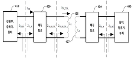
도 4는 본 발명의 일 실시예에 따른 전자기 공진 방식을 지원하는 무선 전력 전송 시스템의 등가 회로도이다.4 is an equivalent circuit diagram of a wireless power transmission system supporting an electromagnetic resonance method according to an embodiment of the present invention.
상세하게, 도 4는 후술할 레퍼런스 파라메터들이 측정되는 등가 회로상에서의 인터페이스 지점을 보여준다.In detail, FIG. 4 shows the interface points on an equivalent circuit in which reference parameters to be described later are measured.
이하에서는, 상기 도 4에 표시된 레퍼런스 파라메터들의 의미를 간단히 설명하기로 한다.Hereinafter, the meaning of the reference parameters shown in FIG. 4 will be briefly described.
ITX와 ITX _COIL은 각각 무선 전력 송신기의 매칭 회로(또는 매칭 네트워크)(420)에 인가되는 RMS(Root Mean Square) 전류와 무선 전력 송신기의 송신 공진기 코일(425)에 인가되는 RMS 전류를 의미한다.I TX and I TX _COIL mean the RMS (Root Mean Square) current applied to the matching circuit (or matching network) 420 of the wireless power transmitter and the RMS current applied to the transmitting
ZTX _IN 은 무선 전력 송신기의 전원부/증폭기/필터(410) 후단의 입력 임피던스(Input Impedance)와 매칭 회로(420) 전단의 입력 임피던스(Input Impedance)를 의미한다.Z TX _IN means the input impedance of the input impedance of the rear end of the power supply / amplifier /
ZTX _IN_COIL은 매칭 회로(420) 후단 및 송신 공진기 코일(425) 전단에서의 입력 임피던스를 의미한다.Z TX _IN_COIL means the input impedance of the
L1과 L2는 각각 송신 공진기 코일(425)의 인덕턴스(Inductance) 값과 수신 공진기 코일(427)의 인덕턴스 값을 의미한다.L1 and L2 denote the inductance value of the transmitting
ZRX _IN은 무선전력수신기의 매칭 회로(430) 후단과 무선전력수신기의 필터/정류기/부하(440) 전단에서의 입력 임피던스를 의미한다.Z RX _IN means the input impedance of the filter / rectifier /
본 발명의 일 실시예에 따른 무선 전력 전송 시스템의 동작에 사용되는 공진 주파수는 6.78MHz ± 15㎑일 수 있다.The resonance frequency used in operation of the wireless power transmission system according to an embodiment of the present invention may be 6.78 MHz ± 15 kHz.
또한, 일 실시예에 따른 무선 전력 전송 시스템은 복수의 무선 전력 수신기에 대한 동시 충전-즉, 멀티 충전-을 제공할 수 있으며, 이 경우, 무선 전력 수신기가 새로 추가되거나 삭제되더라도 남아 있는 무선 전력 수신기의 수신 파워 변화량은 소정 기준치 이상을 초과하지 않도록 제어될 수 있다. 일 예로, 수신 파워 변화량은 ±10%일 수 있으나 이에 국한되지는 않는다. 만약, 수신 파워 변화량이 기준치 이상 초과되지 않도록 제어하는 것이 불가능할 경우, 무선 전력 송신기는 새롭게 추가된 무선 전력 수신기로부터 전력 전송 요청을 수락하지 않을 수도 있다.In addition, a wireless power transmission system according to an embodiment may provide simultaneous charging - i.e., multi-charging - for a plurality of wireless power receivers, in which case the remaining wireless power receivers Can be controlled so as not to exceed a predetermined reference value or more. For example, the received power variation may be +/- 10%, but is not limited thereto. If it is not possible to control the received power change amount to exceed the reference value, the wireless power transmitter may not accept the power transmission request from the newly added wireless power receiver.
상기 수신 파워 변화량을 유지하기 위한 조건은 무선 전력 수신기가 충전 영역에 추가 또는 삭제 시 기존 무선 전력 수신기와 중첩되지 않아야 한다.The condition for maintaining the received power variation should not overlap the existing wireless power receiver when the wireless power receiver is added to or removed from the charging area.
무선 전력 수신기의 매칭 회로(430)가 정류기에 연결된 경우, 상기 ZTX _IN의 실수부(Real Part)는 정류기의 부하 저항-이하, RRECT이라 명함-과 역의 관계일 수 있다. 즉, RRECT의 증가는 ZTX _IN을 감소시키고, RRECT의 감소는 ZTX _IN을 증가시킬 수 있다.When the
본 발명에 따른 공진기 정합 효율(Resonator Coupling Efficiency)은 수신공진기 코일에서 부하(440)로 전달되는 파워를 송신공진기 코일(425)에서 공진 주파수 대역에 실어주는 파워로 나누어 산출되는 최대 파워 수신 비율일 수 있다. 무선 전력 송신기와 무선 전력 수신기 사이의 공진기 정합 효율은 송신공진기의 레퍼런스 포트 임피던스(ZTX_IN)과 수신공진기의 레퍼런스 포트 임피던스(ZRX _IN)가 완벽하게 매칭되는 경우에 산출될 수 있다.The resonator coupling efficiency according to the present invention is the maximum power receiving ratio calculated by dividing the power transmitted from the receiving resonator coil to the
하기 표 3은 본 발명의 일 실시예에 따른 무선 전력 송신기의 등급 및 무선 전력 수신기의 클래스에 따른 최소 공진기 정합 효율의 예이다.Table 3 below is an example of the minimum resonator matching efficiency according to the class of the wireless power transmitter and the class of the wireless power receiver according to an embodiment of the present invention.
만약, 복수의 무선 전력 수신기가 사용될 경우, 상기 표 3에 표시된 클래스 및 카테고리에 대응되는 최소 공진기 정합 효율은 증가할 수도 있다.If a plurality of wireless power receivers are used, the minimum resonator matching efficiency corresponding to the classes and categories shown in Table 3 may increase.
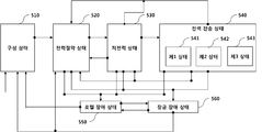
도 5는 본 발명의 일 실시예에 따른 전자기 공진 방식을 지원하는 무선 전력 송신기에서의 상태 천이 절차를 설명하기 위한 상태 천이도이다.5 is a state transition diagram for explaining a state transition procedure in a wireless power transmitter supporting an electromagnetic resonance method according to an embodiment of the present invention.
도 5를 참조하면, 무선 전력 송신기의 상태는 크게 구성 상태(Configuration State, 510), 전력 절약 상태(Power Save State, 520), 저전력 상태(Low Power State, 530), 전력 전송 상태(Power Transfer State, 540), 로컬 장애 상태(Local Fault State, 550) 및 잠금 장애 상태(Latching Fault State, 560)을 포함하여 구성될 수 있다.5, the state of the wireless power transmitter is largely divided into a
무선 전력 송신기에 전력이 인가되면, 무선 전력 송신기는 구성 상태(510)로 천이할 수 있다. 무선 전력 송신기는 구성 상태(510)에서 소정 리셋 타이머가 만료되거나 초기화 절차가 완료되면, 전력 절약 상태(520)로 천이할 수 있다.When power is applied to the wireless power transmitter, the wireless power transmitter can transition to the
전력 절약 상태(520)에서, 무선 전력 송신기는 비콘 시퀀스를 생성하여 공진 주파수 대역을 통해 전송할 수 있다.In the
여기서, 무선 전력 송신기는 전력 절약 상태(520)에 진입한 후 소정 시간 이내에 비콘 시퀀스가 개시될 수 있도록 제어할 수 있다. 일 예로, 무선 전력 송신기는 전력 절약 상태(520) 천이 후 50ms 이내에 비콘 시퀀스가 개시될 수 있도록 제어할 수 있으나, 이에 국한되지는 않는다.Here, the wireless power transmitter can control the beacon sequence to be started within a predetermined time after entering the
전력 절약 상태(520)에서, 무선 전력 송신기는 무선 전력 수신기를 감지하기 위한 제1 비콘 시퀀스(First Beacon Sequence)를 주기적으로 생성하여 전송하고, 수신 공진기의 임피던스 변화-즉, Load Variation-를 감지할 수 있다. 이하, 설명의 편의를 위해 제1 비콘과 제1 비콘 시퀀스를 각각 Short Beacon과 Short Beacon 시퀀스라 명하기로 한다.In the
특히, Short Beacon 시퀀스는 무선 전력 수신기가 감지되기 전까지 무선 전력 송신기의 대기 전력이 절약될 수 있도록 짧은 구간 동안(tSHORT _BEACON) 일정 시간 간격(tCYCLE)으로 반복 생성되어 전송될 수 있다. 일 예로, tSHORT _BEACON은 30ms이하, tCYCLE은 250ms ±5 ms로 각각 설정될 수 있다. 또한, Short Beacon의 전류 세기는 소정 기준치이상이고, 일정 시간 구간 동안 점증적으로 증가될 수 있다. 일 예로, Short Beacon의 최소 전류 세기는 상기 표 2의 카테고리 2 이상의 무선 전력 수신기가 감지될 수 있도록 충분히 크게 설정될 수 있다.In particular, Short Beacon sequences are generated repeatedly with a short period (t SHORT _BEACON) a predetermined time interval (t CYCLE) to be a standby power of the wireless transmitter power saving until the wireless power receiver detection may be transmitted. For example, t SHORT _BEACON is less than 30ms, t CYCLE can be respectively set to 250ms ± 5 ms. Also, the current intensity of the short beacon is not less than a predetermined reference value, and can be gradually increased for a predetermined time period. For example, the minimum current intensity of the Short Beacon may be set to be sufficiently large such that a category 2 or higher wireless power receiver of Table 2 above can be sensed.
본 발명에 따른 무선 전력 송신기는 Short Beacon에 따른 수신 공진기에서의 리액턴스(reactance) 및 저항(resistance) 변화를 감지하기 위한 소정 센싱 수단이 구비될 수 있다.The wireless power transmitter according to the present invention may be provided with a sensing means for sensing reactance and resistance change in the reception resonator according to the short beacon.
또한, 전력 절약 상태(520)에서, 무선 전력 송신기는 무선 전력 수신기의 부팅(Booting) 및 응답에 필요한 충분한 전력을 공급하기 위한 제2 비콘 시퀀스를 주기적으로 생성하여 전송할 수 있다. 이하, 설명의 편의를 위해 제2 비콘과 제2 비콘 시퀀스를 각각 Long Beacon과 Long Beacon 시퀀스라 명하기로 한다.In addition, in the
즉, 무선 전력 수신기는 제2 비콘 시퀀스를 통해 부팅이 완료되면, 대역외 통신 채널을 통해 소정 응답 신호를 브로드캐스팅할 수 있다.That is, the wireless power receiver may broadcast a predetermined response signal over the out-of-band communication channel when booting is completed via the second beacon sequence.
특히, Long Beacon 시퀀스는 무선 전력 수신기의 부팅에 필요한 충분한 전원을 공급하기 위해 Short Beacon에 비해 상대적으로 긴 구간 동안(tLONG_BEACON)동안 일정 시간 간격(tLONG _BEACON_PERIOD)으로 생성되어 전송될 수 있다. 일 예로, tLONG _BEACON은 105 ms+5 ms, tLONG _BEACON_PERIOD 은 850ms로 각각 설정될 수 있으며, Long Beacon의 전류 세기는 Short Beacon의 전류 세기에 비해 상대적으로 강할 수 있다. 또한, Long Beacon은 전송 구간 동안 일정 세기의 파워가 유지될 수 있다.In particular, Long Beacon sequences are generated at a predetermined time interval (t LONG _BEACON_PERIOD) while for a relatively long period (t LONG_BEACON) than the Short Beacon be sent in order to provide sufficient power required by the boot of the wireless power receiver. For example, t LONG _BEACON can be set to 105 ms + 5 ms, and t LONG _BEACON_PERIOD can be set to 850 ms, respectively. The current intensity of the long beacon can be relatively strong compared to the current intensity of the short beacon. Also, the long beacon can maintain the power of a certain intensity during the transmission period.
이 후, 무선 전력 송신기는 수신 공진기의 임피던스 변화가 감지된 후, 무선 전력 송신기는 Long Beacon 전송 구간 동안 소정 응답 시그널의 수신을 대기할 수 있다. 이하, 설명의 편의를 위해 상기 응답 시그널을 광고 시그널(Advertisement Signal)이라 명하기로 한다. 여기서, 무선 전력 수신기는 공진 주파수 대역과는 상이한 대역외 통신 주파수 대역을 통해 광고 시그널을 브로드캐스팅할 수 있다.Thereafter, the wireless power transmitter may wait for the reception of a predetermined response signal during the long beacon transmission interval after the impedance change of the reception resonator is detected. Hereinafter, for convenience of explanation, the response signal will be referred to as an advertisement signal. Here, the wireless power receiver may broadcast an advertisement signal over an out-of-band communication frequency band that is different from the resonant frequency band.
일 예로, 광고 시그널은 해당 대역외 통신 표준에 정의된 메시지를 식별하기 위한 메시지 식별 정보, 무선 전력 수신기가 적법한 또는 해당 무선 전력 송신기에 호환 가능한 수신기인지를 식별하기 위한 고유한 서비스 또는 무선 전력 수신기 식별 정보, 무선 전력 수신기의 출력 파워 정보, 부하에 인가되는 정격 전압/전류 정보, 무선 전력 수신기의 안테나 이득 정보, 무선 전력 수신기의 카테고리를 식별하기 위한 정보, 무선 전력 수신기 인증 정보, 과전압 보호 기능의 탑재 여부에 관한 정보, 무선 전력 수신기에 탑재된 소프트웨어 버전 정보 중 적어도 하나를 포함할 수 있다.In one example, the advertisement signal includes message identification information for identifying a message defined in the out-of-band communication standard, a unique service for identifying whether the wireless power receiver is legitimate or compatible with the wireless power transmitter, Information on the output power of the wireless power receiver, rated voltage / current information applied to the load, antenna gain information of the wireless power receiver, information for identifying the category of the wireless power receiver, wireless power receiver authentication information, And software version information mounted on the wireless power receiver.
무선 전력 송신기는 광고 시그널이 수신되면, 전력 절약 상태(520)에서 저전력 상태(530)로 천이한 후, 무선 전력 수신기와의 대역외 통신 링크를 설정할 수 있다. 연이어, 무선 전력 송신기는 설정된 대역외 통신 링크를 통해 무선 전력 수신기에 대한 등록 절차를 수행할 수 있다. 일 예로, 대역외 통신이 블루투스 저전력 통신인 경우, 무선 전력 송신기는 무선 전력 수신기와 블루투스 페어링을 수행하고, 페어링된 블루투스 링크를 통해 서로의 상태 정보, 특성 정보 및 제어 정보 중 적어도 하나를 교환할 수 있다.The wireless power transmitter may establish an out-of-band communication link with the wireless power receiver after transitioning from a
무선 전력 송신기가 저전력 상태(530)에서 대역외 통신을 통해 충전을 개시하기 위한 소정 제어 신호-즉, 무선 전력 수신기가 부하에 전력을 전달하도록 요청하는 소정 제어 신호-를 무선 전력 수신기에 전송하면, 무선 전력 송신기의 상태는 저전력 상태(530)에서 전력 전송 상태(540)로 천이될 수 있다.If the wireless power transmitter transmits a predetermined control signal to initiate charging via out-of-band communication in the
만약, 저전력 상태(530)에서 대역외 통신 링크 설정 절차 또는 등록 절차가 정상적으로 완료되지 않은 경우, 무선 전력 송신기의 상태는 저전력 상태(530)에서 전력 절약 상태(520)에 천이될 수 있다.If the out-of-band communication link establishment procedure or registration procedure in the
무선 전력 송신기는 각 무선 전력 수신기와의 접속을 위한 별도의 분리된 링크 만료 타이머(Link Expiration Timer)가 구동될 수 있으며, 무선 전력 수신기는 소정 시간 주기로 무선 전력 송신기에 자신이 존재함을 알리는 소정 메시지를 링크 만료 타이머가 만료되기 이전에 전송해야 한다. 링크 만료 타이머는 상기 메시지가 수신될 때마다 리셋되며, 링크 만료 타이머가 만료되지 않으면 무선 전력 수신기와 무선 전력 수신기 사이에 설정된 대역외 통신 링크는 유지될 수 있다.The wireless power transmitter may be driven with a separate Link Expiration Timer for connection to each wireless power receiver and the wireless power receiver may transmit a predetermined message indicating that it is present in the wireless power transmitter at a predetermined time period Should be sent before the link expiration timer expires. The link expiration timer is reset each time the message is received, and the out-of-band communication link established between the wireless power receiver and the wireless power receiver may be maintained if the link expiration timer does not expire.
만약, 저전력 상태(530) 또는 전력 전송 상태(540)에서, 무선 전력 송신기와 적어도 하나의 무선 전력 수신기 사이에 설정된 대역외 통신 링크에 대응되는 모든 링크 만료 타이머가 만료된 경우, 무선 전력 송신기의 상태는 전력 절약 상태(520)로 천이될 수 있다.If all the link expiration timers corresponding to the out-of-band communication link established between the wireless power transmitter and the at least one wireless power receiver have expired in the
또한, 저전력 상태(530)의 무선 전력 송신기는 무선 전력 수신기로부터 유효한 광고 시그널이 수신되면 소정 등록 타이머를 구동시킬 수 있다. 이때, 등록 타이머가 만료되면, 저전력 상태(530)의 무선 전력 송신기는 전력 절약 상태(520)로 천이할 수 있다. 이때, 무선 전력 송신기는 등록에 실패하였음을 알리는 소정 알림 신호를 무선 전력 송신기에 구비된 알림 표시 수단-예를 들면, LED 램프, 디스플레이 화면, 비퍼(beeper) 등을 포함함-을 통해 출력할 수도 있다.In addition, the wireless power transmitter in the
또한, 전력 전송 상태(540)에서, 무선 전력 송신기는 접속된 모든 무선 전력 수신기의 충전이 완료되면, 저전력 상태(530)로 천이될 수 있다.In addition, in the
특히, 무선 전력 수신기는 구성 상태(510), 로컬 장애 상태(550) 및 잠금 장애 상태(560)를 제외한 나머지 상태에서 새로운 무선 전력 수신기의 등록을 허용할 수 있다.In particular, the wireless power receiver may allow registration of a new wireless power receiver in states other than the
또한, 무선 전력 송신기는 전력 전송 상태(540)에서 무선 전력 수신기로부터 수신되는 상태 정보에 기반하여 전송 전력을 동적으로 제어할 수 있다.In addition, the wireless power transmitter can dynamically control the transmit power based on state information received from the wireless power receiver in the power transmit
이때, 무선 전력 수신기로부터 무선 전력 송신기에 전송되는 수신기 상태 정보는 요구 전력 정보, 정류기 후단에서 측정된 전압 및/또는 전류 정보, 충전 상태 정보, 과전류 및/또는 과전압 및/또는 과열 상태를 통보하기 위한 정보, 과전류 또는 과전압에 따라 부하에 전달되는 전력을 차단하거나 감소시키는 수단이 활성화되었는지 여부를 지시하는 정보 중 적어도 하나를 포함할 수 있다. 이때, 수신기 상태 정보는 미리 지정된 주기로 전송되거나 특정 이벤트가 발생될 때마다 전송될 수 있다. 또한, 상기 과전류 또는 과전압에 따라 부하에 전달되는 전력을 차단하거나 감소시키는 수단은 ON/OFF 스위치, 제너다이오드 중 적어도 하나를 이용하여 제공될 수 있다.At this time, the receiver status information transmitted from the wireless power receiver to the wireless power transmitter may include information on required power information, voltage and / or current information measured at the rear end of the rectifier, charge status information, overcurrent and / or overvoltage and / Information indicating whether or not the means for interrupting or reducing the electric power delivered to the load in accordance with the information, the overcurrent, or the overvoltage is activated. At this time, the receiver status information may be transmitted at a predetermined period or transmitted every time a specific event is generated. In addition, the means for interrupting or reducing the electric power delivered to the load in accordance with the overcurrent or overvoltage may be provided using at least one of an ON / OFF switch and a zener diode.
본 발명의 다른 일 실시예에 따른 무선 전력 수신기로부터 무선 전력 송신기에 전송되는 수신기 상태 정보는 무선 전력 수신기에 유선으로 외부 전원이 연결되었음을 알리는 정보, 대역외 통신 방식이 변경되었음을 알리는 정보-일 예로, NFC(Near Field Communication)에서 BLE(Bluetooth Low Energy) 통신으로 변경될 수 있음- 중 적어도 하나를 더 포함할 수도 있다.The receiver status information transmitted from the wireless power receiver to the wireless power transmitter according to another embodiment of the present invention includes information indicating that the external power is connected to the wireless power receiver by wire, information indicating that the out-of-band communication method is changed, And may be changed from NFC (Near Field Communication) to BLE (Bluetooth Low Energy) communication.
본 발명의 또 다른 일 실시예에 따른 무선 전력 송신기는 자신의 현재 가용한 전력, 무선 전력 수신기 별 우선 순위, 접속된 무선 전력 수신기의 개수 중 적어도 하나에 기반하여 무선 전력 수신기 별 수신해야 할 파워 세기를 적응적으로 결정할 수도 있다. 여기서, 무선 전력 수신기 별 파워 세기는 해당 무선 전력 수신기의 정류기에서 처리 가능한 최대 파워 대비 얼마의 비율로 파워를 수신해야 하는지로 결정될 수 있다.In accordance with another embodiment of the present invention, a wireless power transmitter may be configured to determine a power intensity to be received by a wireless power receiver based on at least one of the current available power, the priority of each wireless power receiver, May be adaptively determined. Here, the power intensity by the wireless power receiver can be determined as to how much power should be received in proportion to the maximum power that can be processed by the rectifier of the corresponding wireless power receiver.
이 후, 무선 전력 송신기는 결정된 파워 세기에 관한 정보가 포함된 소정 전력 제어 명령을 해당 무선 전력 수신기에 전송할 수 있다. 이때, 무선 전력 수신기는 무선 전력 송신기에 의해 결정된 파워 세기로 전력 제어가 가능한지 여부를 판단하고, 판단 결과를 소정 전력 제어 응답 메시지를 통해 무선 전력 송신기에 전송할 수 있다.The wireless power transmitter may then send a predetermined power control command to the wireless power receiver that includes information regarding the determined power strength. At this time, the wireless power receiver can determine whether power control is possible based on the power intensity determined by the wireless power transmitter, and transmit the determination result to the wireless power transmitter through the predetermined power control response message.
본 발명의 다른 일 실시예에 따른 무선 전력 수신기는 무선 전력 송신기의 전력 제어 명령에 따라 무선 전력 제어가 가능한지 여부를 지시하는 소정 수신기 상태 정보를 상기 전력 제어 명령을 수신하기 이전에 전송할 수도 있다.The wireless power receiver according to another embodiment of the present invention may transmit predetermined receiver state information indicating whether wireless power control is possible according to a power control command of the wireless power transmitter before receiving the power control command.
전력 전송 상태(540)는 접속된 무선 전력 수신기의 전력 수신 상태에 따라 제1 상태(541), 제2 상태(542) 및 제3 상태(543) 중 어느 하나의 상태일 수 있다.The
일 예로, 제1 상태(541)는 무선 전력 송신기에 접속된 모든 무선 전력 수신기의 전력 수신 상태가 정상 전압인 상태임을 의미할 수 있다.In one example, the
제2 상태(542)는 무선 전력 송신기에 접속된 적어도 하나의 무선 전력 수신기의 전력 수신 상태가 저전압 상태이고 고전압 상태인 무선 전력 수신기가 존재하지 않음을 의미할 수 있다.The
제3 상태(543)는 무선 전력 송신기에 접속된 적어도 하나의 무선 전력 수신기의 전력 수신 상태가 고전압 상태임을 의미할 수 있다.The
무선 전력 송신기는 전력 절약 상태(520) 또는 저전력 상태(530) 또는 전력 전송 상태(540)에서 시스템 오류가 감지되면, 잠금 장애 상태(560)로 천이될 수 있다.The wireless power transmitter may transition to a
잠금 장애 상태(560)의 무선 전력 송신기는 접속된 모든 무선 전력 수신기가 충전 영역에서 제거된 것으로 판단되면, 구성 상태(510) 또는 전력 절약 상태(520)로 천이할 수 있다.The wireless power transmitter in the
또한, 잠금 장애 상태(560)에서, 무선 전력 송신기는 로컬 장애가 감지되면, 로컬 장애 상태(550)로 천이할 수 있다. 여기서, 로컬 장애 상태(550)인 무선 전력 송신기는 로컬 장애가 해제되면, 다시 잠금 장애 상태(560)로 천이될 수 있다.Further, in the
반면, 구성 상태(510), 전력 절약 상태(520), 저전력 상태(530), 전력 전송 상태(540) 중 어느 하나의 상태에서 로컬 장애 상태(550)로 천이된 경우, 무선 전력 송신기는 로컬 장애가 해제되면, 구성 상태(510)로 천이될 수 있다.On the other hand, when transitioning from a state of either
무선 전력 송신기는 로컬 장애 상태(550)로 천이되면, 무선 전력 송신기에 공급되는 전원을 차단할 수도 있다. 일 예로, 무선 전력 송신기는 과전압, 과전류, 과열 등의 장애가 감지되면 로컬 장애 상태(550)로 천이될 수 있으나 이에 국한되지는 않는다.The wireless power transmitter may shut off the power supplied to the wireless power transmitter if it transitions to the
일 예로, 무선 전력 송신기는 과전류, 과전압, 과열 등이 감지되면, 무선 전력 수신기에 의해 수신되는 전력의 세기를 감소시키기 위한 소정 전력 제어 명령을 접속된 적어도 하나의 무선 전력 수신기에 전송할 수도 있다.For example, the wireless power transmitter may transmit a predetermined power control command to the connected at least one wireless power receiver to reduce the strength of the power received by the wireless power receiver, if an over-current, over-voltage,
다른 일 예로, 무선 전력 송신기는 과전류, 과전압, 과열 등이 감지되면, 무선 전력 수신기의 충전을 중단시키기 위한 소정 제어 명령을 접속된 적어도 하나의 무선 전력 수신기에 전송할 수도 있다.In another example, the wireless power transmitter may send a predetermined control command to the connected at least one wireless power receiver to stop the charging of the wireless power receiver if an overcurrent, overvoltage, overheating, or the like is sensed.
상기와 같은 전력 제어 절차를 통해, 무선 전력 송신기는 과전압, 과전류, 과열 등에 따른 기기 파손을 미연에 방지할 수 있다.Through the above-described power control procedure, the wireless power transmitter can prevent the device from being damaged due to overvoltage, overcurrent, overheat or the like.
무선 전력 송신기는 송신 공진기의 출력 전류의 세기가 기준치 이상인 경우, 잠금 장애 상태(560)로 천이할 수 있다. 이때, 잠금 장애 상태(560)로 천이된 무선 전력 송신기는 송신 공진기의 출력 전류의 세기를 미리 지정된 시간 동안 기준치 이하가 되도록 시도할 수 있다. 여기서, 상기 시도는 미리 지정된 회수 동안 반복 수행될 수 있다. 만약, 반복 수행에도 불구하고, 잠금 장애 상태(560)가 해제되지 않는 경우, 무선 전력 송신기는 소정 알림 수단을 이용하여 사용자에게 잠금 장애 상태(560)가 해제되지 않음을 지시하는 소정 알림 신호를 송출할 수 있다. 이때, 무선 전력 송신기의 충전 영역에 위치한 모든 무선 전력 수신기가 사용자에 의해 충전 영역에서 제거되면, 잠금 장애 상태(560)가 해제될 수 있다.The wireless power transmitter may transition to the
반면, 송신 공진기의 출력 전류의 세기가 미리 지정된 시간 이내에 기준치 이하로 떨어지거나 상기 미리 지정된 반복 수행 동안 송신 공진기의 출력 전류의 세기가 기준치 이하로 떨어지는 경우, 잠금 장애 상태(560)는 자동으로 해제될 수 있으며, 이때, 무선 전력 송신기의 상태는 잠금 장애 상태(560)에서 전력 절약 상태(520)로 자동 천이되어 무선 전력 수신기에 대한 감지 및 식별 절차를 다시 수행할 수 있다.On the other hand, if the intensity of the output current of the transmission resonator falls below the reference value within a predetermined time, or the intensity of the output current of the transmission resonator falls below the reference value during the predetermined repetition, the
전력 전송 상태(540)의 무선 전력 송신기는 연속된 전력을 송출하고, 무선 전력 수신기의 상태 정보 및 미리 정의된 최적 전압 영역(Optimal Voltage Region) 설정 파라메터에 기반하여 적응적으로 송출 전력을 제어할 수 있다.The wireless power transmitter in the
일 예로, 최적 전압 영역(Optimal Voltage Region) 설정 파라메터는 저전압 영역을 식별하기 위한 파라메터, 최적 전압 영역을 식별하기 위한 파라메터, 고전압 영역을 식별하기 위한 파라메터, 과전압 영역을 식별하기 위한 파라메터 중 적어도 하나를 포함할 수 있다.For example, the Optimal Voltage Region setting parameter may include at least one of a parameter for identifying the low voltage region, a parameter for identifying the optimum voltage region, a parameter for identifying the high voltage region, and a parameter for identifying the overvoltage region .
무선 전력 송신기는 무선 전력 수신기의 전력 수신 상태가 저전압 영역에 있으면, 송출 전력을 증가시키고, 고전압 영역에 있으면, 송출 전력을 감소시킬 수 있다.The wireless power transmitter can increase the transmission power if the power reception state of the wireless power receiver is in the low voltage region, and reduce the transmission power if it is in the high voltage region.
또한, 무선 전력 송신기는 전력 전송 효율이 최대화되도록 송출 전력을 제어할 수도 있다.The wireless power transmitter may also control the transmit power to maximize the power transmission efficiency.
또한, 무선 전력 송신기는 무선 전력 수신기에 의해 요구된 전력량의 편차가 기준치 이하가 되도록 송출 전력을 제어할 수도 있다.The wireless power transmitter may also control the transmit power so that the deviation of the amount of power required by the wireless power receiver is below a reference value.
또한, 무선 전력 송신기는 무선 전력 수신기의 정류기 출력 전압이 소정 과전압 영역에 도달한 경우-즉, Over Voltage가 감지된 경우-, 전력 전송을 중단할 수도 있다.The wireless power transmitter may also stop transmitting power when the rectifier output voltage of the wireless power receiver reaches a predetermined overvoltage range-that is, when Over Voltage is detected.
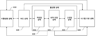
도 6은 본 발명의 일 실시예에 따른 전자기 공진 방식을 지원하는 무선 전력 수신기의 상태 천이도이다.6 is a state transition diagram of a wireless power receiver supporting an electromagnetic resonance method according to an embodiment of the present invention.
도 6을 참조하면, 무선 전력 수신기의 상태는 크게 비활성화 상태(Disable State, 610), 부트 상태(Boot State, 620), 활성화 상태(Enable State, 630)(또는, On state) 및 시스템 오류 상태(System Error State, 640)을 포함하여 구성될 수 있다.6, the state of the wireless power receiver is largely divided into a
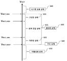
이때, 무선 전력 수신기의 상태는 무선 전력 수신기의 정류기단에서의 출력 전압의 세기-이하, 설명의 편의를 위해 VRECT이라 명함-에 기반하여 결정될 수 있다.At this time, the state of the wireless power receiver may be determined based on the intensity of the output voltage at the rectifier end of the wireless power receiver - hereinafter referred to as V RECT for convenience of explanation.
활성화 상태(630)는 VRECT의 값에 따라 최적 전압 상태(Optimum Voltage State, 631), 저전압 상태(Low Voltage State, 632) 및 고전압 상태(High Voltage State, 633)로 구분될 수 있다.The activated
비활성화 상태(610)의 무선 전력 수신기는 측정된 VRECT 값이 미리 정의된 VRECT_BOOT 값보다 크거나 같으면, 부트 상태(620)로 천이할 수 있다.The wireless power receiver in the
부트 상태(620)에서, 무선 전력 수신기는 무선 전력 송신기와의 대역외 통신 링크를 설정하고 VRECT 값이 부하단에 요구되는 전력에 도달할 때까지 대기할 수 있다.In the
부트 상태(620)의 무선 전력 수신기는 VRECT 값이 부하단에 요구되는 전력에 도달된 것이 확인되면, 활성화 상태(630)로 천이하여 충전을 시작할 수 있다.The wireless power receiver in the
활성화 상태(630)의 무선 전력 수신기는 충전이 완료되거나 충전이 중단된 것이 확인되면, 부트 상태(620)로 천이될 수 있다.The wireless power receiver in the
또한, 활성화 상태(630)의 무선 전력 수신기는 소정 시스템 오류가 감지되면, 시스템 오류 상태(640)로 천이할 수 있다. 여기서, 시스템 오류는 과전압, 과전류 및 과열뿐만 아니라 미리 정의된 다른 시스템 오류 조건이 포함될 수 있다.In addition, the wireless power receiver in the
또한, 활성화 상태(630)의 무선 전력 수신기는 VRECT 값이 VRECT _BOOT 값 이하로 떨어지면, 비활성화 상태(610)로 천이될 수도 있다.In addition, the wireless power receiver in the
또한, 부트 상태(620) 또는 시스템 오류 상태(640)의 무선 전력 수신기는 VRECT 값이 VRECT_BOOT 값 이하로 떨어지면, 비활성화 상태(610)로 천이될 수도 있다.In addition, the wireless power receiver in the
이하에서는, 활성화 상태(630)내에서의 무선 전력 수신기의 상태 천이를 후술할 도 7을 참조하여 상세히 설명하기로 한다.Hereinafter, the state transition of the wireless power receiver within the
도 7은 본 발명의 일 실시예에 따른 전자기 공진 방식에 있어서의 VRECT에 따른 무선 전력 수신기의 동작 영역을 설명하기 위한 도면이다.7 is a view for explaining an operation region of a wireless power receiver according to V RECT in the electromagnetic resonance method according to an embodiment of the present invention.
도 7을 참조하면, VRECT 값이 소정 VRECT _ BOOT 보다 작으면, 무선 전력 수신기는 비활성화 상태(610)에 유지된다.Referring to Figure 7, V RECT If the value is less than the predetermined V RECT _ BOOT, the wireless power receiver is held in the inactive state (610).
이 후, VRECT 값이 VRECT _BOOT 이상으로 증가되면, 무선 전력 수신기는 부트 상태(620)로 천이되며, 미리 지정된 시간 이내에 광고 시그널을 브로드캐스팅할 수 있다. 이 후, 광고 시그널이 무선 전력 송신기에 의해 감지되면, 무선 전력 송신기는 대역외 통신 링크 설정을 위한 소정 연결 요청 시그널을 무선 전력 수신기에 전송할 수 있다.When Thereafter, V RECT value is increased above V RECT _BOOT, the wireless power receiver and changes to the
무선 전력 수신기는 대역외 통신 링크가 정상적으로 설정되고, 등록에 성공한 경우, VRECT 값이 정상적인 충전을 위한 정류기에서의 최소 출력 전압-이하, 설명의 편의를 위해 VRECT _ MIN이라 명함-에 도달할 때까지 대기할 수 있다.The wireless power receiver is normally set to communicate the out-of-band link, if a successful registration, V RECT value of the minimum output voltage of the rectifier for a normal charge-to below, for convenience of explanation V RECT _ MIN as business card is reached You can wait until.
VRECT 값이 VRECT _MIN을 초과하면, 무선 전력 수신기의 상태는 부트 상태(620)에서 활성화 상태(630)로 천이되며 부하에 충전을 시작할 수 있다.When V RECT value exceeds V RECT _MIN, status of the wireless power receiver and transitions to the
만약, 활성화 상태(630)에서 VRECT 값이 과전압을 판단하기 위한 소정 기준치인 VRECT_MAX을 초과하면, 무선 전력 수신기는 활성화 상태(630)에서 시스템 오류 상태(640)로 천이될 수 있다.If, in the
도 7를 참조하면, 활성화 상태(630)는 VRECT의 값에 따라 저전압 상태(Low Voltage State, 632), 최적 전압 상태(Optimum Voltage State, 631) 및 고전압 상태(High Voltage State, 633)로 구분될 수 있다.Referring to FIG. 7, the
저전압 상태(632)는 VRECT _BOOT <= VRECT <= VRECT _ MIN인 상태를 의미하고, 최적 전압 상태(631)은 VRECT _MIN < VRECT <=VRECT _ HIGH인 상태를 의미하고, 고전압 상태(633)는 VRECT _HIGH < VRECT <=VRECT _ MAX인 상태를 의미할 수 있다.
특히, 고전압 상태(633)로 천이된 무선 전력 수신기는 부하에 공급되는 전력을 차단하는 동작을 미리 지정된 시간-이하 설명의 편의를 위해 고전압 상태 유지 시간이라 명함- 동안 유보시킬 수도 있다. 이때, 고전압 상태 유지 시간은 고전압 상태(633)에서 무선 전력 수신기 및 부하에 피해가 발생되지 않도록 미리 결정될 수 있다.In particular, the wireless power receiver transited to the
무선 전력 수신기는 시스템 오류 상태(640)로 천이되면, 과전압 발생을 지시하는 소정 메시지를 미리 지정된 시간 이내에 대역외 통신 링크를 통해 무선 전력 송신기에 전송할 수 있다.When the wireless power receiver transitions to the
또한, 무선 전력 수신기는 시스템 오류 상태(630)에서 과전압에 따른 부하의 피해를 방지하기 위해 구비된 과전압 차단 수단을 이용하여 부하에 인가되는 전압을 제어할 수도 있다. 여기서, 과전압 차단 수단으로 ON/OFF 스위치 또는/및 제너다이오드 등이 사용될 수 있다. The wireless power receiver may also control the voltage applied to the load using overvoltage blocking means provided to prevent damage to the load due to the overvoltage in the
상기 실시예에서는 무선 전력 수신기에 과전압이 발생되어 시스템 오류 상태(640)로 천이된 경우, 무선 전력 수신기에서의 시스템 오류 대응 방법 및 수단을 설명하고 있으나 이는 하나의 실시예에 불과하며, 본 발명의 다른 실시예는 무선 전력 수신기에 과열, 과전류 등에 의해서도 시스템 오류 상태로 천이될 수도 있다.Although a method and means for responding to a system error in a wireless power receiver when an overvoltage is generated in the wireless power receiver and transitioned to a
일 예로, 과열에 따라 시스템 오류 상태로 천이된 경우, 무선 전력 수신기는 과열 발생을 알리는 소정 메시지를 무선 전력 송신기에 전송할 수 있다. 이때, 무선 전력 수신기는 구비된 냉각팬 등을 구동하여 내부 발생된 열을 감소시킬 수도 있다.As an example, if the system transitions to a system fault state due to overheating, the wireless power receiver may send a message to the wireless power transmitter indicating the occurrence of overheating. At this time, the wireless power receiver may drive a cooling fan or the like to reduce internally generated heat.
본 발명의 다른 일 실시예에 따른 무선 전력 수신기는 복수의 무선 전력 송신기와 연동하여 무선 전력을 수신할 수도 있다. 이 경우, 무선 전력 수신기는 실제 무선 전력을 수신하기로 결정된 무선 전력 송신기와 실제 대역외 통신 링크가 설정된 무선 전력 송신기가 서로 상이한 것으로 판단되면, 시스템 오류 상태(640)로 천이할 수도 있다.A wireless power receiver according to another embodiment of the present invention may receive wireless power in cooperation with a plurality of wireless power transmitters. In this case, the wireless power receiver may transition to a
도 8은 본 발명의 일 실시예에 따른 전자기 유도 방식의 무선 충전 시스템을 설명하기 위한 도면이다.8 is a view for explaining a wireless charging system of an electromagnetic induction type according to an embodiment of the present invention.
도 8을 참조하면, 전자기 유도 방식의 무선 충전 시스템은 무선 전력 송신기(800)와 무선 전력 수신기(850)을 포함한다. 무선 전력 수신기(850)를 포함하는 전자 기기를 무선 전력 송신기(800)상에 위치시키면 무선 전력 송신기(800)와 무선 전력 수신기(850)의 코일은 전자기장에 의해 서로 결합될 수 있다.Referring to FIG. 8, an electromagnetic induction wireless charging system includes a
무선 전력 송신기(800)는 전력 전송을 위한 전자기장을 생성하기 위해 전력 신호를 변조하고, 주파수를 변경할 수 있다. 무선 전력 수신기(850)는 무선 통신 환경에 적합하도록 설정된 프로토콜에 따른 전자기 신호를 복조하여 전력을 수신하고, 수신된 전력의 세기에 기반하여 무선 전력 송신기(800)의 송출 전력 세기를 제어하기 위한 소정 피드백 신호를 인-밴드 통신을 통해 무선 전력 송신기(800)에 전송할 수 있다. 일 예로, 무선 전력 송신기(800)는 전력 제어를 위한 제어 신호에 따라 동작 주파수를 제어하여 송출 전력을 증가시키거나 감소시킬 수 있다.The
전송되는 전력의 양(혹은 증가/감소)은 무선 전력 수신기(850)에서 무선 전력 송신기(800)로 전달되는 피드백신호를 이용하여 제어될 수 있다. 또한, 무선 전력 수신기(850)와 무선 전력 송신기(800) 사이의 통신은 상술한 피드백신호를 이용하는 인 밴드(in-band) 통신에만 한정되는 것은 아니며, 별도 통신 모듈을 구비한 아웃 오브 밴드 (out-of-band) 통신을 이용하여 이루어질 수도 있다. 예를 들어, 블루투스, BLE(Bluetooth Low Energy), NFC, Zigbee 등의 근거리 무선통신 모듈이 이용될 수도 있다.The amount of power transmitted (or increased / decreased) may be controlled using a feedback signal transmitted from the
전자기 유도 방식에서 무선 전력 송신기(800)와 무선 전력 수신기(850) 사이의 상태 정보 및 제어 신호 교환을 위한 프로토콜은 주파수 변조 방식이 사용될 수 있다. 상기 프로토콜을 통해 장치 식별 정보, 충전 상태 정보, 전력 제어 신호 등이 교환될 수 있다.In the electromagnetic induction method, a frequency modulation method can be used as a protocol for exchanging state information and control signals between the
본 발명의 일 실시예에 따른 무선 전력 송신기(800)는 상기 도 8에 도시된 바와 같이, 전력 신호를 생성하는 신호 발생기(820), 무선 전력 수신기(850)로부터 전달되는 피드백 신호를 감지할 수 있는 전원 공급단(V_Bus, GND) 사이에 위치한 코일(L1) 및 캐패시터(C1, C2), 및 신호 발생기(820)에 의해 동작이 제어되는 스위치(SW1, SW2)를 포함한다. 신호 발생기(820)는 코일(L1)을 통해 전달된 피드백 신호의 복조를 위한 복조부(824), 주파수 변경을 위한 주파수 구동부(826), 변조부(824)와 주파수 구동부(826)을 제어하기 위한 송신 제어부(822)를 포함하여 구성될 수 있다. 코일(L1)을 통해 전달된 피드백 신호는 복조부(824)에 의해 복조된 후 송신 제어부(822)로 입력되고, 송신 제어부(822)는 복조된 신호에 기반하여 주파수 구동부(826)를 제어하여 코일(L1)로 전달되는 전력 신호의 주파수를 변경할 수 있다.8, the
무선 전력 수신기(850)는 코일(L2)을 통해 피드백 신호를 전송하기 위한 변조부(852), 코일(L2)을 통해 수신된 교류(AC) 신호를 DC 신호로 변환하기 위한 정류부(854), 변조부(852)와 정류부(854)를 제어하기 위한 수신 제어기(860)를 포함할 수 있다. 수신 제어기(860)는 정류기(854) 및 기타 무선 전력 수신기(850)의 동작에 필요한 전원을 공급하기 위한 전원 공급부(862), 정류기(854)가 출력 DC 전압을 충전 대상(부하, 868)의 충전 요건에 맞는 DC 전압으로 변경하기 위한 DC-DC 변환부(864), 변환된 전력이 출력되는 부하(868), 및 수신 전력 상태 및 충전 대상의 상태 등을 무선 전력 송신기(800)에 제공하기 위한 피드백 신호를 발생시키는 피드백 통신부(866)을 포함할 수 있다.The
전자기 유도 방식을 지원하는 무선 충전 시스템의 동작 상태는 크게 대기 상태, 신호 탐지 상태, 식별 확인 상태, 전력 전송 상태, 충전 완료 상태로 구분될 수 있다. 서로 다른 동작 상태로의 변환은 무선 전력 수신기(850)와 무선 전력 송신기(800) 사이의 피드백 통신 결과에 따라 이루어질 수 있다. 대기 상태와 신호 탐지 상태 사이의 변환은 무선 전력 수신기(850)의 존재 여부를 감지하기 위한 소정 수신기 탐지 방법을 통해 이루어질 수 있다.The operation state of the wireless charging system supporting the electromagnetic induction method can be largely classified into a standby state, a signal detection state, an identification confirmation state, a power transmission state, and a charge completion state. Conversion to different operating states may be accomplished in accordance with the feedback communication result between the
도 9는 본 발명의 일 실시예에 따른 전자기 유도 방식을 지원하는 무선 전력 송신기의 상태 천이도이다.9 is a state transition diagram of a wireless power transmitter supporting an electromagnetic induction method according to an embodiment of the present invention.
도 9에 도시된 바와 같이, 무선 전력 송신기의 동작 상태는 크게 대기 상태(STANDBY, 910), 신호 탐지 상태(PING, 920), 식별 확인 상태(IDENTIFICATION, 930), 전력 전송 상태(POWER TRANSFER, 940) 및 충전 완료 상태(END OF CHARGE, 950)로 구분될 수 있다.9, the operation state of the wireless power transmitter is largely divided into a standby state (STANDBY) 910, a signal detection state (PING) 920, an
도 9를 참조하면, 대기 상태(910) 동안 무선 전력 송신기는 충전 가능한 수신 장치가 위치하는지를 감지하기 위해 충전 영역을 감시한다. 충전 가능한 수신 장치를 감지하기 위해 무선 전력 송신기는 자기장(magnetic field), 정전 용량(capacitance), 혹은 유도 용량(inductance) 등의 변화를 감시하는 방법이 사용될 수 있다. 충전 가능한 수신 장치가 발견되면, 무선 전력 송신기는 대기 상태(910)에서 신호 탐지 상태(920)로 천이할 수 있다(S912).Referring to FIG. 9, during a
신호 탐지 상태(920)에서 무선 전력 송신기는 충전 가능한 수신 장치와 연결하고 수신 장치가 유효한 무선 충전 기술을 사용하고 있는지를 확인할 수 있다. 또한, 신호 탐지 상태(220)에서는 무선 전력 송신기는 암전류(기생전류, parasitic current)를 발생시키는 또 다른 장치들을 구별해 내기 위한 동작을 수행할 수도 있다.In the
또한, 신호 탐지 상태(920)에서 무선 전력 송신기는 충전 가능한 수신 장치와의 연결을 위해 기 설정된 주파수와 시간에 따른 구조를 가지는 디지털 핑(digital ping)을 송출할 수 있다. 무선 전력 송신기에서 무선 전력 수신기로 충분한 전력 신호가 전달되면, 무선 전력 수신기는 전자기 유도 방식에서 설정된 프로토콜에 따라 전력 신호를 변조하여 응답할 수 있다. 만약, 무선 전력 송신기가 사용하는 무선 충전 기술에 따른 유효 신호가 수신되면, 무선 전력 송신기는 전력 신호의 전송 차단 없이 신호 탐지 상태(920)에서 식별확인상태(930)로 천이할 수 있다(S924). 식별 확인 상태(930)의 동작을 지원하지 않는 무선 전력 송신기의 경우 전력 전송 상태(940)로 천이할 수도 있다(S924 및 S934).Also, in the
만약, 충전 완료 신호를 무선 전력 수신기로부터 받으면, 무선 전력 송신기는 신호 탐지 상태(920)에서 충전 완료 상태(950)로 천이할 수 있다(S926).If a charge complete signal is received from the wireless power receiver, the wireless power transmitter may transition from the
만약, 신호 탐지 상태(920)에서 무선 전력 수신기로부터의 아무런 반응이 감지되지 않으면-일 예로, 소정 시간 동안 피드백 신호가 수신되지 않는 경우를 포함함-, 무선 전력 송신기는 전력 신호의 전송을 차단하고 대기 상태로(910)로 천이할 수도 있다(S922).If no response from the wireless power receiver is detected in the signal detection state 920 - including, for example, when no feedback signal is received for a predetermined time - the wireless power transmitter blocks transmission of the power signal It may transition to the standby state 910 (S922).
무선 전력 송신기에 따라 식별 확인 상태(930)는 선택적으로 포함될 수 있다.Depending on the wireless power transmitter, the
무선 전력 수신기 별 고유한 수신기 식별 정보가 미리 할당되어 유지될 수 있으며, 무선 전력 수신기는 디지털 핑이 감지되면 특정 무선 충전 기술에 따라 충전될 수 있는 기기임을 무선 전력 송신기에 알릴 필요가 있다. 이러한 수신기 식별 정보 확인을 위해 무선 전력 수신기는 자신의 고유한 식별 정보를 피드백 통신을 통해 무선 전력 송신기에 전송할 수 있다.Unique receiver identification information may be preallocated and maintained for each wireless power receiver and the wireless power receiver needs to inform the wireless power transmitter that it is an appliance that can be charged according to a particular wireless charging technique when a digital ping is sensed. To confirm such receiver identification information, the wireless power receiver may transmit its unique identification information to the wireless power transmitter via feedback communication.
식별 확인 상태(930)를 지원하는 무선 전력 송신기는 무선 전력 수신기가 보내온 수신기 식별 정보의 유효성을 판단할 수 있다. 만약, 수신된 수신기 식별 정보가 유효하다고 판단되면, 무선 전력 송신기는 전력 전송 상태(940)로 천이할 수 있다(S936). 만약, 수신된 수신기 식별 정보가 유효하지 않거나 정해진 시간 내에 유효성이 판단되지 않는 경우, 무선 전력 송신기는 전력 신호의 전송을 차단하고 대기 상태(910)로 천이할 수 있다(S932).The wireless power transmitter supporting the
전력 전송 상태(940)에서는 무선 전력 송신기는 무선 전력 수신기로부터 수신되는 피드백 신호에 기반하여 송출 전력의 세기를 제어할 수 있다. 아울러, 전력 전송 상태(940)의 무선 전력 송신기는 예를 들면 새로운 장치의 감지 등으로 인해 발생할 수 있는 적합한 동작 영역과 허용 한계에 대한 위반이 없음을 확인할 수도 있다.In the
만약, 전력 전송 상태(940)에서 소정 충전 완료 신호가 무선 전력 수신기로부터 수신되는 경우, 무선 전력 송신기는 전력 신호의 전송을 중단하고 충전 완료 상태(950)로 천이할 수 있다(S946). 또한, 전력 전송 상태(940)에서 동작 중 내부 온도가 기 설정된 값을 초과하는 경우, 무선 전력 송신기는 전력 신호의 전송을 차단하고 충전 완료 상태(950)로 천이할 수도 있다(S944).If a predetermined charge completion signal is received from the wireless power receiver in the
또한, 전력 전송 상태(940)에서 시스템 오류 등이 감지되는 경우, 무선 전력 송신기는 전력 신호의 전송을 중단하고 대기 상태(910)로 천이할 수도 있다(S942).
새로운 충전 절차는 충전 대상인 수신 기기가 무선 전력 송신기의 충전 영역에서 감지되는 경우 재개될 수 있다.In addition, if a system error or the like is detected in the
앞에서 설명한 바와 같이, 무선 전력 송신기는 무선 전력 수신기로부터 충전 완료 신호가 입력되거나 동작 중 온도가 기 설정된 범위를 넘어서는 경우 충전 완료 상태(950)로 천이할 수 있다.As described above, the wireless power transmitter can transition to the charging completed
만약 충전 완료 상태(950)로의 천이가 충전 완료 신호에 의한 경우라면, 무선 전력 송신기는 전력 신호의 전송을 차단하고 일정 시간 동안 대기할 수도 있다. 여기서 일정 시간은 전자기 유도 방식으로 전력 신호를 전달하기 위해 무선 전력 송신기가 구비한 코일 등의 구성 요소, 충전 영역의 범위, 혹은 충전 동작의 허용 한계 등에 따라 달라질 수 있다. 충전 완료 상태(950)에서 일정 시간이 지난 후, 무선 전력 송신기는 충전 표면에 위치한 무선 전력 수신기와 연결하기 위해 신호 탐지 상태(920)로 천이할 수 있다(S954). 또한, 무선 전력 송신기는 일정 시간 동안 무선 전력 수신 장치가 제거되는지를 인지하기 위해 충전 표면을 감시할 수도 있다. 만약, 무선 전력 수신 장치가 충전 표면에서 제거된 것이 감지되면, 무선 전력 송신 장치는 대기 상태(910)로 천이할 수 있다(S952).If the transition to the fully charged
만약, 충전 완료 상태(S950)로의 천이가 무선 전력 송신기의 내부 온도 때문인 경우, 무선 전력 송신기는 전력 전송을 차단하고 내부 온도 변화를 감시할 수 있다. 만약, 내부 온도가 일정 범위 혹은 값으로 떨어지면, 무선 전력 송신기는 신호 탐지 상태(920)로 천이할 수 있다(S954). 이때 무선 전력 송신기의 상태를 천이시키기 위한 온도 변화 범위 혹은 값은 무선 전력 송신기의 제조 기술과 방법에 따라 달라질 수 있다. 온도 변화를 감시하는 동안 무선 전력 송신기는 무선 전력 수신 장치가 제거되는지를 인지하기 위해 충전 표면을 감시할 수 있다. 만약 무선 전력 수신 장치가 충전 표면에서 제거된 것이 감지되면, 무선 전력 송신기는 대기 상태(910)로 천이할 수 있다(S952).If the transition to the fully charged state (S950) is due to the internal temperature of the wireless power transmitter, the wireless power transmitter may block power transmission and monitor internal temperature changes. If the internal temperature falls to a certain range or value, the wireless power transmitter may transition to signal detection state 920 (S954). The temperature range or value for changing the state of the wireless power transmitter may vary depending on the manufacturing technology and method of the wireless power transmitter. While monitoring temperature changes, the wireless power transmitter may monitor the charging surface to recognize if the wireless power receiving device is removed. If it is detected that the wireless power receiving device has been removed from the charging surface, the wireless power transmitter may transition to the standby state 910 (S952).
도 10은 본 발명의 일 실시예에 따른 무선 충전 시스템의 구조를 설명하기 위한 블록도이다.10 is a block diagram illustrating a structure of a wireless charging system according to an embodiment of the present invention.
도 10을 참조하면, 무선 충전 시스템(1000)은 차량 제어 유닛(1010), 무선 전력 송신기(1020), 및 무선 전력 수신기(1030)를 포함할 수 있으나, 본 발명의 범위는 이에 한정되지 않는다.10, the
차량 제어 유닛(1010)은 차량에 장착되어 차량 내부 통신을 통해 차량의 각 구성(예컨대, 공조 장치)을 제어할 수 있다. 차량 제어 유닛(1010)은 무선 충전 동작을 수행하는 무선 전력 송신기(1020)와 무선 전력 수신기(1030) 중 적어도 하나에 연결되고, 무선 충전 동작에 관련된 충전 상태 정보에 대응하는 메시지를 디스플레이 할 수 있다.The
상기 충전 상태 정보는 특정 무선 전력 수신기에 대해 상기 무선 충전 동작에 연관된 정보들을 통칭하며, 예컨대, 상기 충전 상태 정보는 무선 전력 송신기(1020)와 무선 전력 수신기(1030)가 서로 연결 및 충전이 시작되어 생성되는 충전 연결 정보, 무선 전력 수신기(1030)에 대한 충전이 완료되는 예상 시간의 정보인 충전 완료 예상 시간 정보, 충전 영역 내 이물질의 진입(또는 제거)에 대한 정보인 이물질 감지 정보(또는 이물질 해소 정보), 충전 효율이 비정상(또는 정상)인지 여부에 대한 정보인 배열 보정 정보(또는 배열 보정 완료 정보), 무선 전력 수신기(1030)의 온도가 미리 정해진 온도 범위를 초과(또는 재진입)할 경우 생성되는 이상 온도 정보(이상 온도 해소 정보), 무선 전력 수신기(1030)의 충전이 완료되어 생성되는 충전 완료 정보 등일 수 있다.The charge state information refers to information associated with the wireless charge operation for a particular wireless power receiver, e.g., the charge state information indicates that the
상기 충전 상태 정보는 차량 제어 유닛(1010), 무선 전력 송신기(1020), 및 무선 전력 수신기(1030) 중 어느 하나에 의해 생성되며, 무선 전력 송신기(1020), 또는 무선 전력 수신기(1030)에 의해 생성된 충전 상태 정보는 직접 차량 제어 유닛(1010)으로 전송되거나 다른 구성을 경유하여 차량 제어 유닛(1010)으로 전송될 수 있다. 예컨대, 무선 전력 수신기(1030)에 의해 생성된 충전 상태 정보는 무선 전력 송신기(1020)를 통해 차량 제어 유닛(1010)으로 전송될 수 있다.The charge state information is generated by either the
상기 충전 상태 정보와는 별도로 상태 감지 정보가 정의될 수 있으며, 상기 상태 감지 정보는 상기 충전 상태 정보를 생성하는데 기초가 되는 정보를 의미할 수 있다. 상기 상태 감지 정보는 각 충전 상태 정보에 대한 설명에서 후술하기로 한다.Status sensing information may be defined separately from the charging status information, and the status sensing information may be information based on generation of the charging status information. The state detection information will be described later in the description of each charge state information.
무선 전력 송신기(1020)는 도 1의 무선 전력 송신기(100), 또는 도 8의 무선 전력 송신기(800)에 대응될 수 있으며, 도 1 또는 도 8의 설명으로 대체하기로 한다. 마찬가지로, 무선 전력 수신기(1030)는 도 1의 무선 전력 수신기(200), 또는 도 8의 무선 전력 수신기(850)에 대응될 수 있으며, 도 1 또는 도 8의 설명으로 대체하기로 한다.The
도 11은 도 10에 도시된 무선 전력 송신기가 차량 내부에 설치되는 위치를 설명하기 위한 도면이다.11 is a view for explaining a position where the wireless power transmitter shown in FIG. 10 is installed in a vehicle.
도 10 및 도 11을 참조하면, 무선 충전 시스템(1000)은 차량 내부에 구비될 수 있고, 차량 제어 유닛(1010)은 차량의 헤드 유닛(head unit)의 일부로 구현될 수 있다.10 and 11, the
무선 전력 송신기(1020)는 센터 페시아(center fascia, 1110), 클러스터 상단(1120), 조수석 콘솔 박스(1130), 및 중앙 콘솔 박스(1140) 중 어느 하나에 구비될 수 있으나, 이에 한정되는 것은 아니다. 다른 실시예에 따라, 무선 전력 송신기(1020)는 복수의 위치들에 구비될 수도 있다.The
도 10에서 언급된 상기 충전 영역은 무선 전력 송신기(1020)로부터 무선 전력 수신기(1030)로 무선 전력 전송이 일어날 수 있는 영역을 의미하며, 예컨대, 무선 전력 송신기(1020)가 중앙 콘솔 박스(1140)에 구비될 경우 중앙 콘솔 박스(1140) 내부가 충전 영역이 될 수 있다.10 refers to an area where a wireless power transmission from a
도 12는 도 10에 도시된 무선 충전 시스템의 일 실시예를 나타낸 블록도이다. 도 13 내지 도 19 각각은 디스플레이 유닛에 표시될 수 있는 메시지의 일 예를 나타낸 도면이다.12 is a block diagram showing an embodiment of the wireless charging system shown in FIG. Each of Figs. 13 to 19 is a diagram showing an example of a message that can be displayed on the display unit.
도 12를 참조하면, 무선 충전 시스템(1300)의 각 구성(1310, 1320, 1330)은 도 10에 도시된 동일 명칭의 각 구성(1010, 1020, 1030)에 대응된다. 상기 각 구성(1310, 1320, 1330)은 하드웨어, 소프트웨어, 또는 이들의 조합으로 구현될 수 있다.12, each
차량 제어 유닛(1310)은 제1 제어 및 통신 유닛(1311), 디스플레이 유닛(1312), 및 전력 공급기(1313)를 포함할 수 있다. The
제1 제어 및 통신 유닛(1311)은 차량 제어 유닛(1310) 내부의 구성들을 제어하고, 차량 제어 유닛(1310) 외부와의 데이터 통신을 수행할 수 있다. 제1 제어 및 통신 유닛(1311)은 충전 상태 정보에 대응하는 메시지를 생성하여 디스플레이 유닛(1312)으로 전송할 수 있다. 또한, 제1 제어 및 통신 유닛(1311)은 전력 공급기(1313)를 제어하여 무선 전력 송신기(1320)로 전달되는 전력을 제어할 수 있다.The first control and
디스플레이 유닛(1312)은 차량에 관련된 여러 정보들을 화면을 통해 출력할 수 있으며, LCD 등 디스플레이 장치로 구현될 수 있다. 디스플레이 유닛(1312)은 제1 제어 및 통신 유닛(1311)으로부터 상기 충전 상태 정보에 대응하는 메시지를 수신하여, 상기 메시지를 디스플레이할 수 있다.The
전력 공급기(1313)는 무선 충전 동작을 위한 전력을 공급할 수 있으며, 차량 운행을 위한 배터리일 수 있다.The
무선 전력 송신기(1320)는 제2 제어 및 통신 유닛(1321), 및 전력 변환기(1322)를 포함할 수 있다.The
제2 제어 및 통신 유닛(1321)은 무선 전력 송신기(1320) 내부의 구성들을 제어하고, 무선 전력 송신기(1320) 외부와의 데이터 통신을 수행할 수 있다. 예컨대, 제2 제어 및 통신 유닛(1321)은 도 1에 도시된 주제어부(150), 및 통신부(160)와 실질적으로 동일한 기능을 수행할 수 있다. 또는, 도 8의 무선 전력 송신기(800)에서 송신 제어부(822)와 복조부(824)의 기능을 수행하거나 포함할 수 있다. 전력 변환기(1322)는 차량 제어 유닛(1310)으로부터 전원을 공급받아 이를 변환하여 무선 전력 수신기(1330)로 전달하는 기능을 수행한다. 예컨대, 전력 변환기(1322)는 도 1에 도시된 전원 공급부(110), 전력 변환부(120), 매칭 회로(130), 및 송신 공진기(140)와 실질적으로 동일한 기능을 수행할 수 있다.The second control and
무선 전력 수신기(1330)는 제3 제어 및 통신 유닛(1331), 전력 수신기(1332), 및 부하(1333)를 포함할 수 있다.The
제3 제어 및 통신 유닛(1331)은 무선 전력 수신기(1330) 내부의 구성들을 제어하고, 무선 전력 수신기(1330) 외부와의 데이터 통신을 수행할 수 있다. 예컨대, 제3 제어 및 통신 유닛(1331)은 도 1에 도시된 주제어부(250), 및 통신부(260)와 실질적으로 동일한 기능을 수행할 수 있다. 제3 제어 및 통신유닛(1331)은 도 8의 무선 전력 수신기(850)의 구성에서 수신 제어기(860)과 변조부(852)를 포함하거나, 도 1의 무선 전력 수신기에서 수신기 주제어부(250)과 통신부(260)을 포함할 수도 있다. The third control and
전력 수신기(1332)는 무선 전력 송신기(1320)으로부터 무선 충전 방식(예컨대, 전자기 공진 방식 또는 전자기 유도 방식)으로 전원을 공급받아 이를 변환하여 부하(1333)로 전달하는 기능을 수행한다. 예컨대, 전력 수신기(1332)는 도 1에 도시된 수신 공진기(210), 정류기(220), 및 DC-DC 변환기(230)와 실질적으로 동일한 기능을 수행할 수 있다.The
부하(1333)는 전달된 전력을 축적하는 충전지로 구현될 수 있으며, 예컨대 도 1에 도시된 부하(240)과 실질적으로 동일한 기능을 수행할 수 있다.The
이하, 무선 충전에 관련된 무선 충전 시스템(1300)의 동작을 도 13 내지 도 19를 참조하여 설명하기로 한다.Hereinafter, the operation of the
차량 제어 유닛(1310)과 무선 전력 송신기(1320)는 데이터 통신 및 전력 전송 각각을 위한 유선 케이블로 연결될 수 있으며, 차량 제어 유닛(1310)의 전원이 켜지면 차량 제어 유닛(1310)의 제어에 따라 무선 전력 송신기(1320)의 전원이 켜질 수 있다.The
무선 전력 송신기(1320)와 무선 전력 수신기(1330)와의 통신으로 무선 충전을 위한 준비가 완료되면, 무선 전력 송신기(1320)와 무선 전력 수신기(1330) 간의 무선 전력 전송이 개시될 수 있다. 이때, 무선 전력 송신기(1320)는 무선 전력 송신기(1320)와 무선 전력 수신기(1330)가 서로 연결 및 충전이 시작되어 생성되는 충전 시작 정보 및 무선 전력 수신기(1330)를 식별하기 위한 수신기 식별 정보를 무선 전력 수신기(1330)로부터 수신하여 무선 전력 수신기(1330)의 충전 시작을 알리는 충전 연결 정보를 생성하고, 이를 제1 제어 및 통신 유닛(1311)으로 전달할 수 있다. 제1 제어 및 통신 유닛(1311)은 상기 충전 연결 정보에 대응하는 메시지를 생성할 수 있다. 여기서, 상기 충전 시작 정보는 상태 감지 정보이고, 상기 충전 연결 정보는 충전 상태 정보이다.Wireless power transmission between the
예컨대, 수신기 식별 정보가 식별 번호 1인 스마트폰(최초로 등록된 스마트폰)임을 나타내고, 충전 시작 정보가 무선 충전이 시작되었음을 나타낼 경우, 제1 제어 및 통신 유닛(1311)은 "스마트폰 #1의 무선 충전이 시작되었습니다"라는 메시지를 생성하고, 디스플레이 유닛(1312)은 도 13에 도시된 메시지(M1)를 디스플레이 할 수 있다. 메시지(M1)을 비롯해 본 명세서에서 언급되는 메시지들(M1~M11)은 차량 운행자의 주의 분산을 줄이기 위해 디스플레이되는 것과 별도로 제1 제어 및 통신 유닛(1311)에 연결된 스피커(미도시)를 통해 동일한 내용이 출력될 수 있다.For example, if the receiver identification information indicates that the smartphone is the identification number 1 (the first registered smartphone) and the charging start information indicates that the wireless charging has started, the first control and
충전이 개시된 후, 무선 전력 송신기(1320)는 무선 전력 수신기(1330)로부터 수신기 식별 정보, 및 수신기 전력 정보를 수신하고, 수신기 식별 정보, 및 수신기 전력 정보를 기초로 무선 전력 수신기(1330)의 충전이 완료되는 예상 시간을 계산하여 충전 완료 예상 시간 정보를 생성할 수 있다. 상기 수신기 전력 정보는 부하(1333)의 총 전력 용량, 잔여 전력 용량, 단위 시간당 평균 전력 소모량, 부하(1333)에 실질적으로 전달되는 전력에 대한 정보인 부하 수신 전력 정보, 현재 시간 정보 등의 정보를 포함한다. 단위 시간당 평균 전력 소모량은 무선 전력 수신기(1330)가 장착된 스마트폰이 사용중인 경우 사용패턴을 분석하여 정확한 충전 완료 예상 시간 정보를 생성하기 위해 사용된다. 여기서, 상기 수신기 전력 정보는 상태 감지 정보이고, 상기 충전 완료 예상 시간 정보는 충전 상태 정보이다.After charging is initiated, the
무선 전력 송신기(1320)는 충전 완료 예상 시간 정보를 제1 제어 및 통신 유닛(1311)으로 전달할 수 있다. 제1 제어 및 통신 유닛(1311)은 상기 충전 완료 예상 시간 정보에 대응하는 메시지를 생성할 수 있다.The
예컨대, 수신기 식별 정보가 식별 번호 1인 스마트폰임을 나타내고, 충전 완료 예상 시간 정보가 오후 2시 30분에 무선 충전이 완료됨을 나타낼 경우, 제1 제어 및 통신 유닛(1311)은 "스마트폰 #1의 예상 충전 완료 시간 오후 2시 30분"이라는 메시지를 생성하고, 디스플레이 유닛(1312)은 도 14에 도시된 메시지(M2)를 디스플레이 할 수 있다. 여기서, 충전 완료 예상 시간 정보가 현재 시각으로부터 3시간 후에 무선 충전이 완료됨을 나타낼 경우 메시지(M2)에 "오후 2시 30분" 대신 "3시간 후"의 문구가 표시될 수도 있다.For example, if the receiver identification information indicates that the smartphone is identification number 1, and if the estimated completion time information indicates that the wireless charging is completed at 2:30 PM, the first control and
또한, 무선 전력 송신기(1320)는 무선 전력 수신기(1330)로부터 수신기 식별 정보, 및 수신기 전력 정보를 주기적으로 수신하거나 무선 전력 수신기(1330)가 상태 변화 감지 보고 신호를 수신한 뒤 새로운 수신기 전력 정보를 무선 전력 송신기(1320)로 전송함에 의해, 무선 전력 송신기(1320)는 무선 전력 수신기(1330)의 충전이 완료되는 예상 시간을 재계산하여 새로운 충전 완료 예상 시간 정보를 생성하여 이에 대한 메시지가 디스플레이 되도록 할 수 있다.In addition, the
상기 상태 변화 감지 보고 신호는 무선 전력 수신기(1330)가 장착된 전자기기(예컨대, 스마트폰)로부터 전송될 수 있으며, 전자 기기의 전원 ON/OFF 상태 변화에 관한 정보, 어플리케이션 실행에 관한 정보, 전자기기의 전력 소모 변화에 관한 정보 중 적어도 하나를 포함할 수 있다.The status change detection report signal may be transmitted from an electronic device (e.g., a smart phone) equipped with the
이는 차량 주행 중 다양한 원인에 의해 충전 완료 예상 시간이 변화되는 상황을 신속하게 감지하여, 사용자에게 알림으로써 부적절한 충전 상태를 바로 잡을 수 있도록 할 수 있다.This makes it possible to promptly detect a situation in which the expected completion time of the charging is changed due to various causes during driving the vehicle, and to inform the user that the charging state can be corrected inadequately.
충전 진행 중, 무선 전력 송신기(1320)는 무선 전력 수신기(1330)로부터 수신한 수신기 식별 정보, 현재 수신 전력 정보와 전력 변환기(1322)의 송신 전력에 대한 정보인 송신 전력 정보, 채널 설정 결과 정보, 및/또는 무선 전력 수신기(1330)의 임피던스 변화를 기초로, 이상 충전 현상을 감지하여 이물질 감지 정보 또는 배열 보정 정보를 생성할 수 있다. 여기서, 상기 현재 수신 전력 정보, 상기 송신 전력 정보, 상기 채널 설정 결과 정보, 상기 임피던스 변화 등은 상태 감지 정보이고, 상기 이물질 감지 정보 또는 상기 배열 보정 정보는 충전 상태 정보이다.During charging, the
상기 이물질 감지 정보는 충전 데크 내에 이물질이 존재하여 이상 충전 현상이 발생하는 경우를 나타내는 정보이다. 상기 이물질 감지 정보는 무선 전력 송신기(1320)가 임피던스 변화를 통해 물체를 감지한 뒤 채널 설정을 위한 신호를 전송하고 상기 신호에 대한 피드백(feedback) 신호의 수신 여부에 대한 정보인 채널 설정 결과 정보에 따라 생성될 수 있다. 만일, 상기 채널 설정 결과 정보가 채널 설정을 위한 신호의 전송에도 불구하고 피드백(feedback)을 받지 못하였음을 나타낼 경우, 무선 전력 송신기(1320)는 상기 채널 설정 결과 정보를 기초로 상기 물체를 이물질로 판단할 수 있다.The foreign substance sensing information is information indicating a case where an abnormal charging phenomenon occurs due to the presence of a foreign substance in the charging deck. The foreign substance sensing information is transmitted to the
상기 배열 보정 정보는 무선 전력 수신기(1330)의 위치가 잘못되어(특히, 전자기 유도 방식에서 전송 가능 거리에서 벗어날 경우) 이상 충전 현상이 발생하는 경우를 나타내는 정보이다. 상기 배열 보정 정보는 상기 송신 전력 정보의 송신 전력에 비해 현재 수신 전력 정보의 부하(1333)로 전달되는 전력이 현저하게 낮은 경우 또는 무선 전력 수신기(1330)의 임피던스가 소정의 정상 범위를 벗어날 경우에 생성될 수 있다. 여기서, 현저하게 낮은 경우는 상기 전달되는 전력과 상기 송신 전력의 비율(예컨대, 50 %) 이하인 경우로 미리 정의될 수 있으나, 본 발명의 범위는 이에 한정되지 않는다.The arrangement correction information is information indicating a case where an abnormal charging phenomenon occurs when the position of the
무선 전력 송신기(1320)는 이물질 감지 정보 또는 배열 보정 정보를 제1 제어 및 통신 유닛(1311)으로 전달할 수 있다. 제1 제어 및 통신 유닛(1311)은 상기 이물질 감지 정보 또는 상기 배열 보정 정보에 대응하는 메시지를 생성할 수 있다.The
예컨대, 수신기 식별 정보가 식별 번호 1인 스마트폰임을 나타내고, 이물질 감지 정보가 전달된 경우, 제1 제어 및 통신 유닛(1311)은 "스마트폰 #1의 충전 상태가 정상적이지 않습니다 충전 데크 내의 이물질 유무를 확인하세요!"라는 메시지를 생성하고, 디스플레이 유닛(1312)은 도 15a에 도시된 메시지(M3a)를 디스플레이 할 수 있다.For example, when the foreign substance detection information is transmitted, the first control and
또한, 수신기 식별 정보가 식별 번호 1인 스마트폰임을 나타내고, 배열 보정 정보가 전달된 경우, 제1 제어 및 통신 유닛(1311)은 "스마트폰 #1의 충전 상태가 정상적이지 않습니다 충전 연결 상태를 확인하세요!"라는 메시지를 생성하고, 디스플레이 유닛(1312)은 도 15b에 도시된 메시지(M3b)를 디스플레이 할 수 있다.If the receiver identification information indicates that the smartphone is identification number 1, and the arrangement correction information is transmitted, the first control and
실시예에 따라, 제1 제어 및 통신 유닛(1311)은 차량 제어 유닛(1310) 내의 스피커(미도시)를 이용하여 메시지(M3a, M3b)와 함께 경고 알림 소리를 출력할 수 있다. 메시지(M3a, M3b) 또는 상기 경고 알림 소리는 후술할 이상 충전 현상 해결 정보가 수신될 때까지 계속하여 출력될 수 있다.According to an embodiment, the first control and
또한, 이상 충전 현상이 감지됨에 따라 무선 전력 송신기(1320)는 무선 전력 수신기(1330)의 충전이 완료되는 예상 시간을 재계산하여 새로운 충전 완료 예상 시간 정보를 생성하여 이에 대한 메시지가 메시지(M3a, M3b)와 함께 디스플레이 되도록 할 수 있다. 여기서, 함께 디스플레이되는 방식은 두 메시지가 한 화면에 동시에 표시되거나, 일정 시간 간격으로 번갈아 표시될 수 있으나, 본 발명의 범위는 이에 한정되지 않는다.In addition, as the abnormal charging phenomenon is detected, the
사용자가 메시지(M3a, M3b)를 확인한 뒤, 충전 데크 내의 이물질(예컨대, 도전성 물질)을 제거하거나, 무선 전력 송신기(1320)와 무선 전력 수신기(1330) 간의 연결 상태를 정상으로 복구한 경우, 무선 전력 송신기(1320)는 이상 충전 현상이 해소되었음을 감지하여 이상 충전 현상 해결 정보를 생성하고 제1 제어 및 통신 유닛(1311)으로 전달할 수 있다. 제1 제어 및 통신 유닛(1311)은 상기 이상 충전 현상 해결 정보에 대응하는 메시지를 생성할 수 있다. 여기서, 이상 충전 현상이 해소되었음을 감지할 수 있는 정보(예컨대, 임피던스 변화, 현재 수신 전력 정보 등)는 상태 감지 정보이고, 상기 이상 충전 현상 해결 정보는 충전 상태 정보이다.When the user confirms the messages M3a and M3b and then removes foreign matter (e.g., conductive material) in the charging deck or restores the connection state between the
예컨대, 수신기 식별 정보가 식별 번호 1인 스마트폰임을 나타내고, 이상 충전 현상 해결 정보가 전달된 경우, 제1 제어 및 통신 유닛(1311)은 "스마트폰 #1의 충전상태가 정상으로 복구되었습니다"라는 메시지를 생성하고, 디스플레이 유닛(1312)은 도 16에 도시된 메시지(M4)를 디스플레이 할 수 있다.For example, if the receiver identification information indicates that the smartphone is identification number 1, and the abnormal charging phenomenon solving information is transmitted, the first control and
또한, 이상 충전 현상이 해결됨에 따라 무선 전력 송신기(1320)는 무선 전력 수신기(1330)의 충전이 완료되는 예상 시간을 재계산하여 새로운 충전 완료 예상 시간 정보를 생성하여 이에 대한 메시지(M2)가 디스플레이 되도록 할 수 있다.In addition, as the abnormal charging phenomenon is resolved, the
충전 진행 중, 무선 전력 송신기(1320)는 무선 전력 수신기(1330)로부터 수신한 수신기 식별 정보, 및 온도 정보를 기초로, 이상 온도 현상을 감지하여 이상 온도 정보를 생성할 수 있다. 예컨대, 상기 이상 온도 현상은 무선 전력 수신기(1330)의 온도가 정상 온도 범위를 초과할 경우에 감지될 수 있다. 여기서, 정상 온도 범위는 무선 전력 수신기(1330)가 장착된 기기의 특성을 고려하여 정해질 수 있으나, 본 발명의 범위는 이에 한정되지 않는다. 또한, 상기 온도 정보는 상태 감지 정보이고, 상기 이상 온도 정보는 충전 상태 정보이다.During charging, the
무선 전력 송신기(1320)는 이상 온도 정보를 제1 제어 및 통신 유닛(1311)으로 전달할 수 있다. 제1 제어 및 통신 유닛(1311)은 상기 이상 온도 정보에 대응하는 메시지를 생성할 수 있다.The
예컨대, 수신기 식별 정보가 식별 번호 1인 스마트폰임을 나타내고, 이상 온도 정보가 전달된 경우, 제1 제어 및 통신 유닛(1311)은 "스마트폰 #1의 온도가 매우 높습니다 쿨링 유닛을 가동합니다!"라는 메시지를 생성하고, 디스플레이 유닛(1312)은 도 17에 도시된 메시지(M5)를 디스플레이 할 수 있다. 실시예에 따라, 제1 제어 및 통신 유닛(1311)은 차량 제어 유닛(1310) 내의 스피커(미도시)를 이용하여 메시지(M5)와 함께 경고 알림 소리를 출력할 수 있다. 메시지(M5) 또는 상기 경고 알림 소리는 후술할 이상 온도 현상 해결 신호가 수신될 때까지 계속하여 출력될 수 있다. 또한, 사용자의 차량 운행에 방해가 되지 않도록, 메시지(M5) 또는 상기 경고 알림 소리가 일정 주기로 출력될 수 있음은 물론이며, 사용자의 조작에 의해 더 이상 발생되지 않도록 할 수도 있다.For example, if the receiver identification information is a smartphone with identification number 1, and the abnormal temperature information has been delivered, the first control and
제1 제어 및 통신 유닛(1311)은 충전 데크의 온도를 낮추기 위해 구비되는 쿨링 유닛(미도시)의 동작을 제어할 수 있으며, 상기 이상 온도 정보에 대응하는 메시지를 생성함과 동시에 상기 쿨링 유닛을 작동시킬 수 있다. 차량 내부는 차량 주행 중 무선 충전 동작과는 관계없이 상당한 열이 발생할 수 있으므로, 충전 데크의 온도가 특정 온도 이상 올라갈 경우 자동적으로 상기 쿨링 유닛을 작동시킴으로써 기기의 파손을 미연에 방지할 수 있다.The first control and
상기 쿨링 유닛의 동작으로 무선 전력 수신기(1330)의 온도가 정상 온도 범위 내로 복귀한 경우, 무선 전력 송신기(1320)는 온도 정보로부터 이상 온도 현상이 해소되었음을 감지하여 이상 온도 해결 정보를 생성하고 제1 제어 및 통신 유닛(1311)으로 전달할 수 있다. 제1 제어 및 통신 유닛(1311)은 상기 이상 온도 해결 정보에 대응하는 메시지를 생성할 수 있다. 여기서, 상기 온도 정보는 상태 감지 정보이고, 상기 이상 온도 해결 정보는 충전 상태 정보이다.When the temperature of the
예컨대, 수신기 식별 정보가 식별 번호 1인 스마트폰임을 나타내고, 이상 충전 해결 정보가 전달된 경우, 제1 제어 및 통신 유닛(1311)은 "스마트폰 #1의 온도가 정상으로 복귀되었습니다 쿨링 유닛을 중지합니다!"라는 메시지를 생성하고, 디스플레이 유닛(1312)은 도 18에 도시된 메시지(M6)를 디스플레이 할 수 있다.For example, if the receiver identification information is a smartphone with identification number 1, and the abnormal charging resolution information has been delivered, the first control and
무선 전력 수신기(1330)의 제3 제어 및 통신 유닛(1331)은 부하(1333)의 충전상태를 모니터링하여, 부하(1333)에 대한 충전이 완료되었음을 감지한 경우 수신기 충전 완료 정보를 생성하여 제2 제어 및 통신 유닛(1321)으로 전송할 수 있다. 제2 제어 및 통신 유닛(1321)은 수신기 식별 정보 및 상기 수신기 충전 완료 정보를 기초로 충전 완료 정보를 생성하여 제1 제어 및 통신 유닛(1311)으로 전달할 수 있다. 여기서, 상기 수신기 충전 완료 정보는 상태 감지 정보이고, 상기 충전 완료 정보는 충전 상태 정보이다.The third control and
제1 제어 및 통신 유닛(1311)은 상기 충전 완료 정보에 대응하는 메시지를 생성할 수 있다.The first control and
예컨대, 수신기 식별 정보가 식별 번호 1인 스마트폰임을 나타내고, 충전 완료 정보가 전달된 경우, 제1 제어 및 통신 유닛(1311)은 "스마트폰 #1의 무선 충전이 완료되었습니다"라는 메시지를 생성하고, 디스플레이 유닛(1312)은 도 19에 도시된 메시지(M7)를 디스플레이 할 수 있다.For example, if the receiver identification information indicates that the smartphone is identification number 1, and the charging completion information is transmitted, the first control and
도 20은 도 10에 도시된 무선 충전 시스템의 다른 실시예를 나타낸 블록도이다. 도 21 내지 도 22 각각은 디스플레이 유닛에 표시될 수 있는 메시지의 일 예를 나타낸 도면이다.20 is a block diagram showing another embodiment of the wireless charging system shown in FIG. Each of Figs. 21 to 22 is a diagram showing an example of a message that can be displayed on the display unit.
도 20을 참조하면, 무선 충전 시스템(2000)의 각 구성(2010, 2020, 2030)은 도 10에 도시된 동일 명칭의 각 구성(1010, 1020, 1030)에 대응된다. 또한, 각 구성(2010, 2020, 2030)의 구성 및 동작은 도 12에 도시된 각 구성(1310, 1320, 1330)의 구성 및 동작과 실질적으로 동일하므로 상세한 설명은 생략하기로 한다. 다만, 무선 충전 시스템(2000)은 복수의 무선 전력 수신기들(2030)을 포함하며, 각 무선 전력 수신기(2030-1~2030-3)는 도 12에 도시된 무선 전력 수신기(1330)와 실질적으로 동일하다.20, each
비록 도 20에는 복수의 무선 전력 수신기들(2030)에 3개의 무선 전력 수신기가 포함된 것으로 도시되었으나, 본 발명의 범위는 이에 한정되지 않고 임의의 개수의 무선 전력 수신기들이 포함될 수 있다.Although FIG. 20 shows that a plurality of
이후, 복수의 무선 전력 수신기들(2030)이 포함됨에 따른 동작을 위주로 설명하기로 한다.Hereinafter, operation of the plurality of
각 무선 전력 수신기(2030-1~2030-3)는 도 12 내지 도 19에 대한 설명에서 언급된 각종 정보를 무선 전력 송신기(2020)과 송수신할 수 있다.Each of the wireless power receivers 2030-1 to 2030-3 can transmit and receive various kinds of information mentioned in the description of Figs. 12 to 19 to and from the
특히, 무선 전력 송신기(2020)에 복수의 무선 전력 수신기들(2030-1~2030-3)이 연결되어 충전이 개시된 후, 무선 전력 송신기(2020)는 각 무선 전력 수신기(2030-1~2030-3)로부터 수신기 식별 정보, 및 수신기 전력 정보를 수신하고, 수신기 식별 정보, 및 수신기 전력 정보를 기초로 각 무선 전력 수신기(2030-1~2030-3)의 충전이 완료되는 예상 시간을 계산하여 충전 완료 예상 시간 정보를 생성할 수 있다.In particular, after a plurality of wireless power receivers 2030-1 through 2030-3 are connected to the
무선 전력 송신기(2020)는 각 무선 전력 수신기(2030-1~2030-3)의 충전 완료 예상 시간 정보를 제1 제어 및 통신 유닛(2011)으로 전달할 수 있다. 제1 제어 및 통신 유닛(2011)은 상기 충전 완료 예상 시간 정보에 대응하는 메시지를 생성할 수 있다.The
이때, 3개의 무선 전력 수신기(2030-1~2030-3)마다 우선 순위가 설정될 수 있다. 예컨대, 상기 우선 순위는 무선 전력 송신기(2020)에 연결되는 순서, 무선 전력 수신기(2030-1~2030-3)가 장착된 기기의 종류, 또는 사용자의 선택에 의해 결정될 수 있다. 또한, 무선 전력 송신기(2020)의 총 송신 전력이 100%라 할 때, 무선 전력 수신기(2030-1~2030-3) 각각에 할당되는 충전 전력 점유율은 상기 우선 순위에 따라 결정될 수 있다. 무선 전력 송신기(2020)는 상기 충전 전력 점유율에 따라 각 무선 전력 수신기(2030-1~2030-3)에 대한 송신 전력을 조절할 수 있다.At this time, priority can be set for each of the three wireless power receivers 2030-1 to 2030-3. For example, the priority may be determined by the order in which the
무선 전력 송신기(2020)는 각 무선 전력 수신기(2030-1~2030-3)의 충전 완료 예상 시간 정보와 함께, 각 무선 전력 수신기(2030-1~2030-3)의 우선 순위 정보 및 충전 전력 점유율 정보를 제1 제어 및 통신 유닛(2011)으로 전달할 수 있다. 여기서, 상기 우선 순위 정보 및 상기 충전 전력 점유율 정보는 충전 상태 정보이다.The
도 21에서 무선 전력 수신기(2030-1~2030-3)가 각각 식별 번호가 1인 스마트폰(이하 제1 스마트폰), 식별 번호가 2인 스마트폰(이하 제2 스마트폰), 및 식별 번호가 1인 태블릿(이하 제1 태블릿)에 장착되어 있고 우선 순위가 상기 나열 순서대로 결정되어 있다고 가정한다. 또한, 제1 스마트폰의 예상 충전 완료 시간과 충전 전력 점유율이 오후 1시와 50%이고, 제2 스마트폰의 예상 충전 완료 시간과 충전 전력 점유율이 오후 3시와 30%이고, 제1 태블릿의 예상 충전 완료 시간과 충전 전력 점유율이 오후 6시와 20%이라 가정한다.In FIG. 21, the wireless power receivers 2030-1 to 2030-3 each have a smartphone (hereinafter referred to as a first smartphone) having an identification number of 1, a smartphone having an identification number of 2 (hereinafter referred to as a second smartphone) Is assumed to be mounted on a tablet (hereinafter referred to as " first tablet ") 1 and the priority order is determined in the above listed order. Also, it is assumed that the expected charging completion time and the charging power occupancy rate of the first smartphone are 1:00 and 50%, the expected charging completion time and charging power occupancy rate of the second smartphone are 3:00 and 30% Assume the expected charge completion time and charge power share are 6:00 PM and 20%.
상기 충전전력 점유율은 생략되어 디스플레이 될 수도 있다.The charge power occupancy rate may be omitted and displayed.
만일, 사용자가 제1 태블릿의 충전 속도를 높이고 제1 스마트폰의 충전 속도를 낮추고 싶을 경우, 제1 태블릿과 제1 스마트폰의 우선 순위를 서로 바꾸어야 할 것이다. 이때, 사용자는 메시지(M8)를 확인하여 우선 순위를 변경하는 조작을 수행할 수 있다. 예컨대, 제1 스마트폰에 대응하는 박스를 임계 시간 이상 터치한 상태에서 제1 태블릿에 대응하는 박스보다 아래 위치로 드래그(drag)하고, 제1 태블릿에 대응하는 박스를 임계 시간 이상 터치한 상태에서 제2 스마트폰에 대응하는 박스보다 높은 위치로 드래그하여 우선 순위를 변경할 수 있다.If the user wants to increase the charging speed of the first tablet and lower the charging speed of the first smartphone, the priority order of the first tablet and the first smartphone should be changed. At this time, the user can confirm the message M8 and perform an operation of changing the priority. For example, when a box corresponding to the first smartphone is dragged to a position lower than a box corresponding to the first tablet while touching the box corresponding to the first smartphone for a predetermined time or more, and a box corresponding to the first tablet is touched for more than a threshold time The priority can be changed by dragging it to a position higher than the box corresponding to the second smartphone.
제1 제어 및 통신 유닛(2011)은 사용자의 요청으로 인한 각 무선 전력 수신기(2030-1~2030-3)의 우선 순위 변경 정보를 무선 전력 송신기(2020)로 전달할 수 있다.The first control and
이 경우, 무선 전력 송신기(2020)는 우선 순위 변경 정보에 따라 변경된 각 무선 전력 수신기(2030-1~2030-3)의 우선 순위 정보 및/또는 충전 전력 점유율 정보를 제1 제어 및 통신 유닛(2011)으로 전송할 수 있다. 이에 따라, 제1 태블릿과 제1 스마트폰의 충전 전력 점유율은 각각 50%와 20%로 자동으로 변경될 수 있다.In this case, the
또한, 사용자는 메시지(M8)를 확인하여 충전 전력 점유율을 직접 변경하는 조작을 수행할 수 있다. 예컨대, 제1 태블릿에 대응하는 박스를 연속으로 터치하여 70을 입력하고 제1 스마트폰에 대응하는 박스를 연속으로 터치하여 10을 입력할 수 있다.Further, the user can perform an operation of confirming the message M8 and directly changing the charge power share. For example, a box corresponding to the first tablet may be continuously touched to input 70, and a box corresponding to the first smartphone may be continuously touched to input 10.
제1 제어 및 통신 유닛(2011)은 사용자의 요청으로 인한 각 무선 전력 수신기(2030-1~2030-3)의 충전 전력 점유율 변경 정보를 무선 전력 송신기(2020)로 전달할 수 있다. 이 경우, 무선 전력 송신기(2020)는 충전 전력 점유율 변경 정보에 따라 변경된 각 무선 전력 수신기(2030-1~2030-3)의 우선 순위 정보 및 충전 전력 점유율 정보를 제1 제어 및 통신 유닛(2011)으로 전송할 수 있다.The first control and
도 22에 도시된 메시지(M9)는 사용자가 충전 전력 점유율을 직접 변경하는 조작에 의해 메시지(M8)에 대응하는 우선 순위와 충전 전력 점유율이 변경된 것을 도시한 것이다.The message M9 shown in Fig. 22 shows that the priority and the charge power occupancy corresponding to the message M8 are changed by the operation of directly changing the charge power occupancy by the user.
각 무선 전력 수신기(2030-1~2030-3)의 충전 전력 점유율이 변경되면, 각 무선 전력 수신기(2030-1~2030-3)의 현재 수신 전력 정보가 변경되므로 무선 전력 송신기(2020)는 각 무선 전력 수신기(2030-1~2030-3)의 충전 완료 예상 시간 정보를 새로 계산하여 제1 제어 및 통신 유닛(2011)으로 전달할 수 있다. 도 22에 도시된 메시지(M9)에는 새로 계산된 충전 완료 예상 시간 정보에 따른 각 무선 전력 수신기(2030-1~2030-3)의 예상 충전 시간이 도시되어 있다.When the charging power share of each of the wireless power receivers 2030-1 to 2030-3 is changed, the current received power information of each of the wireless power receivers 2030-1 to 2030-3 is changed, so that the
도 23은 도 10에 도시된 무선 충전 시스템의 또 다른 실시예를 나타낸 블록도이다. 도 24 내지 도 25 각각은 디스플레이 유닛에 표시될 수 있는 메시지의 일 예를 나타낸 도면이다.Fig. 23 is a block diagram showing another embodiment of the wireless charging system shown in Fig. 10. Fig. 24 to 25 are views each showing an example of a message that can be displayed on the display unit.
도 23을 참조하면, 무선 충전 시스템(2300)의 각 구성(2310, 2320, 2330)은 도 10에 도시된 동일 명칭의 각 구성(1010, 1020, 1030)에 대응된다. 또한, 각 구성(2310, 2320, 2330)의 구성 및 동작은 도 12에 도시된 각 구성(1310, 1320, 1330)의 구성 및 동작과 일부를 제외하고는 실질적으로 동일하므로 상세한 설명은 생략하기로 한다.23, each
차량 제어 유닛(2310)과 무선 전력 수신기(2330) 각각은 근거리 통신 유닛(2314, 2334)을 포함할 수 있으며, 각 근거리 통신 유닛(2314, 2334)은 근거리 통신 방식을 이용해 서로간에 데이터를 송수신할 수 있다. 예컨대, 상기 근거리 통신 방식은 블루투스(Bluetooth), 또는 NFC(Near Field Communication) 방식일 수 있으나, 이에 한정되지 않는다.Each of the
무선 전력 송신기(2320)는 무선 전력 수신기(2330)와 연결시 충전 연결 정보 및 수신기 식별 정보를 제1 제어 및 통신 유닛(2311)으로 전송하며, 제1 제어 및 통신 유닛(2311)은 수신기 식별 정보에 대응하는 무선 전력 수신기(2330)에 대해 페어링(paring)을 시도할 수 있다(auto connection 기능).The
각 근거리 통신 유닛(2314, 2334)은 제1 제어 및 통신 유닛(2311)과 제3 제어 및 통신 유닛(2331) 사이의 직접적인 데이터 교환을 중계할 수 있다.Each short-
여기서는, 제1 제어 및 통신 유닛(2311)이 무선 전력 수신기(2330)로부터 근거리 통신 유닛들(2314, 2334)을 통해 수신기 전력 정보를 수신하는 경우를 예로 들어 설명하기로 한다.Here, the case where the first control and
제1 제어 및 통신 유닛(2311)이 무선 전력 수신기(2330)로부터 근거리 통신 유닛들(2314, 2334)을 통해 수신한 수신기 전력 정보에 의해 부하(2333)의 총 전력 용량 및 잔여 전력 용량을 인식할 수 있고, 이를 통해 해당 기기의 충전량을 계산 잔여 충전량 정보를 생성할 수 있다. 여기서, 상기 수신기 전력 정보는 상태 감지 정보이고, 상기 잔여 충전량 정보는 충전 상태 정보이다.The first control and
예컨대, 제1 제어 및 통신 유닛(2311)은 도 14에서와 같은 충전 완료 예상 시간 정보를 수신하고, 근거리 통신 유닛들(2314, 2334)을 통해 수신한 수신기 전력 정보에 의해 인식된 잔여 전력 용량과 총 전력 용량의 비율을 계산한 결과 50%인 경우, 도 14의 메시지(M2) 이외에 제1 스마트폰의 예상 충전 완료 시간과 더불어 제1 스마트폰의 충전량에 대한 정보인 잔여 충전량 정보를 더 포함하는 메시지를 생성할 수 있다. 디스플레이 유닛(2312)은 도 24에 도시된 메시지(M10)를 디스플레이 할 수 있다.For example, the first control and
또한, 제1 제어 및 통신 유닛(2311)은 충전 완료 정보가 전달된 이후, 근거리 통신 유닛들(2314, 2334)을 통해 수신한 수신기 전력 정보에 의해 인식된 잔여 전력 용량과 총 전력 용량의 비율을 계산한 결과가 90%인 경우(충전이 완료된 이후 스마트폰의 사용에 의해 방전이 이루어진 상태), 도 19의 메시지(M7)의 제1 스마트폰의 무선 충전 완료 메시지와 더불어 제1 스마트폰의 잔여 충전량 정보를 더 포함하는 메시지를 생성할 수 있다. 디스플레이 유닛(2312)은 도 25에 도시된 메시지(M11)를 디스플레이 할 수 있다. 사용자는 메시지(M11)를 통해 현재의 제1 스마트폰의 실제적인 충전 상태를 확인할 수 있으며, 필요에 따라 제1 스마트폰의 충전 재개를 지시할 수 있다.Also, the first control and
본 명세서에서는 무선 충전 동작에 관련된 충전 상태 정보가 주로 무선 전력 송신기(1320, 2020, 2320)에 의해 생성되는 것으로 설명하였으나, 다른 실시예에 따라 상기 충전 상태 정보의 전부 또는 일부가 차량 제어 유닛(1310, 2010, 2310), 또는 무선 전력 수신기(1330, 2030, 2330)에 의해 생성될 수 있다.Although it has been described herein that the charging status information related to the wireless charging operation is generated mainly by the
예를 들어, 도 12에서 무선 전력 수신기(1330)가 수신기 식별 정보, 및 수신기 전력 정보를 기초로 무선 전력 수신기(1330)의 충전이 완료되는 예상 시간을 계산하여 충전 완료 예상 시간 정보를 생성하여 무선 전력 송신기(1320)를 통해 차량 제어 유닛(1310)으로 전송할 수 있다. 또는, 차량 제어 유닛(1310)이 수신기 식별 정보, 및 수신기 전력 정보를 무선 전력 송신기(1320)를 통해 수신하여, 이를 기초로 충전 완료 예상 시간 정보를 직접 생성할 수도 있다.For example, in FIG. 12, the
본 발명의 일 실시예에 따른 무선 충전 시스템에 의하면, 무선 충전 동작에 관련된 다양한 정보를 차량 제어 유닛을 통해 출력함으로써, 차량 주행 환경에서 발생할 수 있는 다양한 충전 상태 변화를 사용자가 보다 안전하고 신속하게 인지하고 대처할 수 있도록 하는 효과가 있다.According to the wireless charging system of the present invention, by outputting various information related to the wireless charging operation through the vehicle control unit, it is possible to recognize various charging state changes that may occur in the vehicle traveling environment more safely and promptly And to cope with the problem.
또한, 복수의 포터블 장치들을 충전하는 경우에도, 복수의 포터블 장치들의 무선 충전 상태를 모니터링 및 제어할 수 있는 효과가 있다.In addition, even when a plurality of portable devices are charged, the wireless charging state of a plurality of portable devices can be monitored and controlled.
아울러, 차량 제어 유닛과 무선 전력 수신기 사이의 직접 통신을 통해, 차량 제어 유닛에 보다 다양한 정보가 제공될 수 있도록 할 수 있다.In addition, through direct communication between the vehicle control unit and the wireless power receiver, it is possible to provide more various information to the vehicle control unit.
본 발명은 본 발명의 정신 및 필수적 특징을 벗어나지 않는 범위에서 다른 특정한 형태로 구체화될 수 있음은 당업자에게 자명하다. 따라서, 상기의 상세한 설명은 모든 면에서 제한적으로 해석되어서는 아니되고 예시적인 것으로 고려되어야 한다. 본 발명의 범위는 첨부된 청구항의 합리적 해석에 의해 결정되어야 하고, 본 발명의 등가적 범위 내에서의 모든 변경은 본 발명의 범위에 포함된다.It will be apparent to those skilled in the art that the present invention may be embodied in other specific forms without departing from the spirit or essential characteristics thereof. Accordingly, the above description should not be construed in a limiting sense in all respects and should be considered illustrative. The scope of the present invention should be determined by rational interpretation of the appended claims, and all changes within the scope of equivalents of the present invention are included in the scope of the present invention.
상술한 실시예에 따른 방법은 컴퓨터에서 실행되기 위한 프로그램으로 제작되어 컴퓨터가 읽을 수 있는 기록 매체에 저장될 수 있으며, 컴퓨터가 읽을 수 있는 기록 매체의 예로는 ROM, RAM, CD-ROM, 자기 테이프, 플로피디스크, 광 데이터 저장장치 등이 있으며, 또한 캐리어 웨이브(예를 들어 인터넷을 통한 전송)의 형태로 구현되는 것도 포함한다.The method according to the above-described embodiments may be implemented as a program to be executed by a computer and stored in a computer-readable recording medium. Examples of the computer-readable recording medium include a ROM, a RAM, a CD- , A floppy disk, an optical data storage device, and the like, and may also be implemented in the form of a carrier wave (for example, transmission over the Internet).
컴퓨터가 읽을 수 있는 기록 매체는 네트워크로 연결된 컴퓨터 시스템에 분산되어, 분산방식으로 컴퓨터가 읽을 수 있는 코드가 저장되고 실행될 수 있다. 그리고, 상술한 방법을 구현하기 위한 기능적인(function) 프로그램, 코드 및 코드 세그먼트들은 실시예가 속하는 기술분야의 프로그래머들에 의해 용이하게 추론될 수 있다.The computer readable recording medium may be distributed over a networked computer system so that computer readable code can be stored and executed in a distributed manner. And, functional program, code, and code segments for implementing the above-described method can be easily inferred by programmers in the technical field to which the embodiment belongs.
본 발명은 본 발명의 정신 및 필수적 특징을 벗어나지 않는 범위에서 다른 특정한 형태로 구체화될 수 있음은 당업자에게 자명하다.It will be apparent to those skilled in the art that the present invention may be embodied in other specific forms without departing from the spirit or essential characteristics thereof.
따라서, 상기의 상세한 설명은 모든 면에서 제한적으로 해석되어서는 아니되고 예시적인 것으로 고려되어야 한다. 본 발명의 범위는 첨부된 청구항의 합리적 해석에 의해 결정되어야 하고, 본 발명의 등가적 범위 내에서의 모든 변경은 본 발명의 범위에 포함된다.Accordingly, the above description should not be construed in a limiting sense in all respects and should be considered illustrative. The scope of the present invention should be determined by rational interpretation of the appended claims, and all changes within the scope of equivalents of the present invention are included in the scope of the present invention.
1000: 무선 충전 시스템
1010: 차량 제어 유닛
1020: 무선 전력 송신기
1030: 무선 전력 수신기1000: Wireless charging system
1010: vehicle control unit
1020: Wireless power transmitter
1030: Wireless power receiver
Claims (39)
상기 무선 충전 동작에 관련된 상태 감지 정보에 기초하여 생성되는 충전 상태 정보에 대응하는 메시지를 디스플레이하는 차량 제어 유닛.Connected to at least one of a wireless power transmitter and a wireless power receiver performing a wireless charging operation,
And displays a message corresponding to the charge state information generated based on the state detection information related to the wireless charge operation.
상기 상태 감지 정보는 상기 무선 전력 수신기의 부하의 총 전력 용량, 잔여 전력 용량, 및 부하 수신 전력 정보를 포함하고,
상기 충전 상태 정보는 상기 총 전력 용량, 상기 잔여 전력 용량, 및 상기 부하 수신 전력 정보를 기초로 산출되는 상기 무선 전력 수신기의 충전이 완료되는 예상 시간에 대한 정보인 충전 완료 예상 시간 정보를 포함하는 차량 제어 유닛.The method according to claim 1,
Wherein the status detection information includes a total power capacity, a remaining power capacity, and load received power information of a load of the wireless power receiver,
Wherein the charging state information includes information on estimated charging time, which is information on an estimated time at which charging of the wireless power receiver is completed based on the total power capacity, the remaining power capacity, and the load receiving power information, Control unit.
상기 상태 감지 정보는 채널 설정을 위한 신호를 전송하여 피드백(feedback) 신호의 수신 여부에 대한 정보인 채널 설정 결과 정보 및 임피던스 변화를 포함하고,
상기 충전 상태 정보는 상기 임피던스 변화가 발생하였음에도 상기 채널 설정 결과 정보가 상기 피드백 신호를 수신하지 못함을 나타내는 이물질 감지 정보를 포함하는 차량 제어 유닛.The method according to claim 1,
The state detection information includes a channel setting result information and an impedance change, which are information on whether a feedback signal is received by transmitting a signal for channel setting,
Wherein the charge state information includes foreign matter detection information indicating that the channel setting result information does not receive the feedback signal even though the impedance change has occurred.
상기 상태 감지 정보는 상기 무선 전력 송신기의 송신 전력 정보, 및 상기 무선 전력 수신기의 현재 수신 전력 정보를 포함하고,
상기 충전 상태 정보는 상기 현재 수신 전력 정보와 상기 송신 전력 정보의 비율이 정상 범위를 벗어날 경우 생성되는 배열 보정 정보를 포함하는 차량 제어 유닛.The method according to claim 1,
Wherein the status detection information includes transmission power information of the wireless power transmitter and current reception power information of the wireless power receiver,
Wherein the charging state information includes arrangement correction information that is generated when a ratio of the current received power information to the transmission power information exceeds a normal range.
상기 상태 감지 정보는 상기 무선 전력 송신기의 온도 정보를 포함하고,
상기 충전 상태 정보는 상기 온도 정보에 따른 상기 무선 전력 수신기의 온도가 정상 온도 범위를 벗어날 경우 생성되는 이상 온도 정보를 포함하는 차량 제어 유닛.The method according to claim 1,
Wherein the status detection information includes temperature information of the wireless power transmitter,
Wherein the charging status information includes abnormal temperature information generated when the temperature of the wireless power receiver according to the temperature information is out of the normal temperature range.
상기 차량 제어 유닛은, 상기 이상 온도 정보가 수신될 경우 상기 이상 온도 정보에 따라 상기 무선 전력 수신기의 온도를 감소시키는 쿨링 유닛을 작동시키는 차량 제어 유닛.6. The method of claim 5,
The vehicle control unit activates a cooling unit that reduces the temperature of the wireless power receiver in accordance with the abnormal temperature information when the abnormal temperature information is received.
상기 차량 제어 유닛은, 상기 무선 전력 수신기의 온도가 상기 정상 온도 범위 내로 복귀할 경우 상기 쿨링 유닛의 동작을 중지시키는 차량 제어 유닛.6. The method of claim 5,
The vehicle control unit stops operation of the cooling unit when the temperature of the wireless power receiver returns to the normal temperature range.
상기 상태 감지 정보는 상기 무선 전력 송신기와 상기 무선 전력 수신기가 서로 연결되어 생성되는 충전 시작 정보를 포함하고,
상기 충전 상태 정보는 상기 충전 시작 정보 및 상기 무선 전력 수신기의 수신기 식별 정보에 기초하여 생성되는 충전 연결 정보를 포함하는 차량 제어 유닛.The method according to claim 1,
Wherein the status detection information includes charge start information generated by connecting the wireless power transmitter and the wireless power receiver to each other,
Wherein the charge state information includes charge connection information that is generated based on the charge start information and the receiver identification information of the wireless power receiver.
상기 충전 상태 정보는 상기 무선 전력 수신기가 제공하는 상기 상태 감지 정보에 기초하여 상기 무선 전력 송신기에 의해 생성되어 상기 무선 전력 송신기로부터 수신되는 차량 제어 유닛.The method according to claim 1,
Wherein the state of charge information is generated by the wireless power transmitter based on the state sensing information provided by the wireless power receiver and received from the wireless power transmitter.
상기 충전 상태 정보는 상기 무선 전력 수신기로부터 수신되는 상기 상태 감지 정보에 기초하여 상기 차량 제어 유닛에 의해 생성되는 차량 제어 유닛.The method according to claim 1,
Wherein the charge status information is generated by the vehicle control unit based on the status detection information received from the wireless power receiver.
상기 충전 상태 정보는 상기 무선 전력 수신기에 의해 생성되어 수신되는 차량 제어 유닛.The method according to claim 1,
Wherein the charge status information is generated and received by the wireless power receiver.
상기 무선 충전 동작에 관련된 상태 감지 정보에 기초하여 생성되는 충전 상태 정보에 대응하는 메시지를 디스플레이하는 차량 제어 유닛.A wireless power transmitter and at least one of a plurality of wireless power receivers performing a wireless charging operation,
And displays a message corresponding to the charge state information generated based on the state detection information related to the wireless charge operation.
상기 상태 감지 정보는 상기 무선 전력 수신기의 부하의 총 전력 용량, 잔여 전력 용량, 및 부하 수신 전력 정보를 포함하고,
상기 충전 상태 정보는 상기 총 전력 용량, 상기 잔여 전력 용량, 및 상기 부하 수신 전력 정보를 기초로 산출되는 상기 무선 전력 수신기의 충전이 완료되는 예상 시간에 대한 정보인 충전 완료 예상 시간 정보를 포함하는 차량 제어 유닛.13. The method of claim 12,
Wherein the status detection information includes a total power capacity, a remaining power capacity, and load received power information of a load of the wireless power receiver,
Wherein the charging state information includes information on estimated charging time, which is information on an estimated time at which charging of the wireless power receiver is completed based on the total power capacity, the remaining power capacity, and the load receiving power information, Control unit.
상기 상태 감지 정보는 채널 설정을 위한 신호를 전송하여 피드백(feedback) 신호의 수신 여부에 대한 정보인 채널 설정 결과 정보 및 임피던스 변화를 포함하고,
상기 충전 상태 정보는 상기 임피던스 변화가 발생하였음에도 상기 채널 설정 결과 정보가 상기 피드백 신호를 수신하지 못함을 나타내는 이물질 감지 정보를 포함하는 차량 제어 유닛.13. The method of claim 12,
The state detection information includes a channel setting result information and an impedance change, which are information on whether a feedback signal is received by transmitting a signal for channel setting,
Wherein the charge state information includes foreign matter detection information indicating that the channel setting result information does not receive the feedback signal even though the impedance change has occurred.
상기 상태 감지 정보는 상기 무선 전력 송신기의 송신 전력 정보, 및 상기 무선 전력 수신기의 현재 수신 전력 정보를 포함하고,
상기 충전 상태 정보는 상기 현재 수신 전력 정보와 상기 송신 전력 정보의 비율이 정상 범위를 벗어날 경우 생성되는 배열 보정 정보를 포함하는 차량 제어 유닛.13. The method of claim 12,
Wherein the status detection information includes transmission power information of the wireless power transmitter and current reception power information of the wireless power receiver,
Wherein the charging state information includes arrangement correction information that is generated when a ratio of the current received power information to the transmission power information exceeds a normal range.
상기 상태 감지 정보는 상기 무선 전력 송신기의 온도 정보를 포함하고,
상기 충전 상태 정보는 상기 온도 정보에 따른 상기 무선 전력 수신기의 온도가 정상 온도 범위를 벗어날 경우 생성되는 이상 온도 정보를 포함하는 차량 제어 유닛.13. The method of claim 12,
Wherein the status detection information includes temperature information of the wireless power transmitter,
Wherein the charging status information includes abnormal temperature information generated when the temperature of the wireless power receiver according to the temperature information is out of the normal temperature range.
상기 차량 제어 유닛은, 상기 이상 온도 정보가 수신될 경우 상기 이상 온도 정보에 따라 상기 무선 전력 수신기의 온도를 감소시키는 쿨링 유닛을 작동시키는 차량 제어 유닛.17. The method of claim 16,
The vehicle control unit activates a cooling unit that reduces the temperature of the wireless power receiver in accordance with the abnormal temperature information when the abnormal temperature information is received.
상기 차량 제어 유닛은, 상기 무선 전력 수신기의 온도가 상기 정상 온도 범위 내로 복귀할 경우 상기 쿨링 유닛의 동작을 중지시키는 차량 제어 유닛.17. The method of claim 16,
The vehicle control unit stops operation of the cooling unit when the temperature of the wireless power receiver returns to the normal temperature range.
상기 상태 감지 정보는 상기 무선 전력 송신기와 상기 무선 전력 수신기가 서로 연결되어 생성되는 충전 시작 정보를 포함하고,
상기 충전 상태 정보는 상기 충전 시작 정보 및 상기 무선 전력 수신기의 수신기 식별 정보에 기초하여 생성되는 충전 연결 정보를 포함하는 차량 제어 유닛.13. The method of claim 12,
Wherein the status detection information includes charge start information generated by connecting the wireless power transmitter and the wireless power receiver to each other,
Wherein the charge state information includes charge connection information that is generated based on the charge start information and the receiver identification information of the wireless power receiver.
상기 충전 상태 정보는 상기 무선 전력 수신기가 제공하는 상기 상태 감지 정보에 기초하여 상기 무선 전력 송신기에 의해 생성되어 상기 무선 전력 송신기로부터 수신되는 차량 제어 유닛.13. The method of claim 12,
Wherein the state of charge information is generated by the wireless power transmitter based on the state sensing information provided by the wireless power receiver and received from the wireless power transmitter.
상기 충전 상태 정보는 상기 무선 전력 수신기로부터 수신되는 상기 상태 감지 정보에 기초하여 상기 차량 제어 유닛에 의해 생성되는 차량 제어 유닛.13. The method of claim 12,
Wherein the charge status information is generated by the vehicle control unit based on the status detection information received from the wireless power receiver.
상기 충전 상태 정보는 상기 무선 전력 수신기에 의해 생성되어 수신되는 차량 제어 유닛.13. The method of claim 12,
Wherein the charge status information is generated and received by the wireless power receiver.
상기 복수의 무선 전력 수신기들 각각의 예상 충전 완료 시간 및 충전 전력 점유율을 우선 순위에 따라 디스플레이하는 차량 제어 유닛.13. The method of claim 12,
And displays a predicted charge completion time and a charge power occupancy rate of each of the plurality of wireless power receivers in a priority order.
상기 우선 순위가 변경됨에 따라 변경된 우선 순위에 상응하도록 상기 충전 전력 점유율을 변경하도록 요청하는 차량 제어 유닛.24. The method of claim 23,
And requests to change the charge power occupation rate to correspond to the changed priority as the priority is changed.
상기 충전 전력 점유율이 변경됨에 따라 변경된 충전 전력 점유율에 상응하도록 상기 우선 순위를 변경하도록 요청하는 차량 제어 유닛.24. The method of claim 23,
And requests to change the priority so as to correspond to the changed charge power share as the charge power share is changed.
상기 무선 충전 동작에 관련된 상태 감지 정보에 기초하여 생성되는 충전 상태 정보에 대응하는 메시지를 디스플레이하며,
상기 무선 전력 수신기와 근거리 통신 방식으로 연결되는 차량 제어 유닛.Connected to a wireless power transmitter and a wireless power receiver for performing a wireless charging operation,
Displays a message corresponding to charge status information generated based on status detection information related to the wireless charging operation,
And a vehicle control unit connected to the wireless power receiver in a short distance communication manner.
상기 상태 감지 정보는 상기 무선 전력 수신기의 부하의 총 전력 용량, 잔여 전력 용량, 및 부하 수신 전력 정보를 포함하고,
상기 충전 상태 정보는 상기 총 전력 용량, 상기 잔여 전력 용량, 및 상기 부하 수신 전력 정보를 기초로 산출되는 상기 무선 전력 수신기의 충전이 완료되는 예상 시간에 대한 정보인 충전 완료 예상 시간 정보를 포함하는 차량 제어 유닛.27. The method of claim 26,
Wherein the status detection information includes a total power capacity, a remaining power capacity, and load received power information of a load of the wireless power receiver,
Wherein the charging state information includes information on estimated charging time, which is information on an estimated time at which charging of the wireless power receiver is completed based on the total power capacity, the remaining power capacity, and the load receiving power information, Control unit.
상기 상태 감지 정보는 채널 설정을 위한 신호를 전송하여 피드백(feedback) 신호의 수신 여부에 대한 정보인 채널 설정 결과 정보 및 임피던스 변화를 포함하고,
상기 충전 상태 정보는 상기 임피던스 변화가 발생하였음에도 상기 채널 설정 결과 정보가 상기 피드백 신호를 수신하지 못함을 나타내는 이물질 감지 정보를 포함하는 차량 제어 유닛.27. The method of claim 26,
The state detection information includes a channel setting result information and an impedance change, which are information on whether a feedback signal is received by transmitting a signal for channel setting,
Wherein the charge state information includes foreign matter detection information indicating that the channel setting result information does not receive the feedback signal even though the impedance change has occurred.
상기 상태 감지 정보는 상기 무선 전력 송신기의 송신 전력 정보, 및 상기 무선 전력 수신기의 현재 수신 전력 정보를 포함하고,
상기 충전 상태 정보는 상기 현재 수신 전력 정보와 상기 송신 전력 정보의 비율이 정상 범위를 벗어날 경우 생성되는 배열 보정 정보를 포함하는 차량 제어 유닛.27. The method of claim 26,
Wherein the status detection information includes transmission power information of the wireless power transmitter and current reception power information of the wireless power receiver,
Wherein the charging state information includes arrangement correction information that is generated when a ratio of the current received power information to the transmission power information exceeds a normal range.
상기 상태 감지 정보는 상기 무선 전력 송신기의 온도 정보를 포함하고,
상기 충전 상태 정보는 상기 온도 정보에 따른 상기 무선 전력 수신기의 온도가 정상 온도 범위를 벗어날 경우 생성되는 이상 온도 정보를 포함하는 차량 제어 유닛.27. The method of claim 26,
Wherein the status detection information includes temperature information of the wireless power transmitter,
Wherein the charging status information includes abnormal temperature information generated when the temperature of the wireless power receiver according to the temperature information is out of the normal temperature range.
상기 충전 상태 정보에 대응하는 메시지가 디스플레이되도록 차량 제어 유닛으로 상기 충전 상태 정보를 전송하는 무선 전력 송신기.Generating charge state information based on state detection information related to a wireless charge operation performed on the wireless power receiver,
And transmit the charge state information to the vehicle control unit such that a message corresponding to the charge state information is displayed.
상기 무선 충전 동작에 관련된 상태 감지 정보에 기초하여 생성되는 충전 상태 정보에 대응하는 메시지를 디스플레이하며,
상기 무선 전력 수신기와 근거리 통신 방식으로 연결되는 차량 제어 유닛.A wireless power transmitter and at least one of a plurality of wireless power receivers performing a wireless charging operation,
Displays a message corresponding to charge status information generated based on status detection information related to the wireless charging operation,
And a vehicle control unit connected to the wireless power receiver in a short distance communication manner.
상기 상태 감지 정보는 상기 무선 전력 수신기의 부하의 총 전력 용량, 잔여 전력 용량, 및 부하 수신 전력 정보를 포함하고,
상기 충전 상태 정보는 상기 총 전력 용량, 상기 잔여 전력 용량, 및 상기 부하 수신 전력 정보를 기초로 산출되는 상기 무선 전력 수신기의 충전이 완료되는 예상 시간에 대한 정보인 충전 완료 예상 시간 정보를 포함하는 차량 제어 유닛.33. The method of claim 32,
Wherein the status detection information includes a total power capacity, a remaining power capacity, and load received power information of a load of the wireless power receiver,
Wherein the charging state information includes information on estimated charging time, which is information on an estimated time at which charging of the wireless power receiver is completed based on the total power capacity, the remaining power capacity, and the load receiving power information, Control unit.
상기 상태 감지 정보는 채널 설정을 위한 신호를 전송하여 피드백(feedback) 신호의 수신 여부에 대한 정보인 채널 설정 결과 정보 및 임피던스 변화를 포함하고,
상기 충전 상태 정보는 상기 임피던스 변화가 발생하였음에도 상기 채널 설정 결과 정보가 상기 피드백 신호를 수신하지 못함을 나타내는 이물질 감지 정보를 포함하는 차량 제어 유닛.33. The method of claim 32,
The state detection information includes a channel setting result information and an impedance change, which are information on whether a feedback signal is received by transmitting a signal for channel setting,
Wherein the charge state information includes foreign matter detection information indicating that the channel setting result information does not receive the feedback signal even though the impedance change has occurred.
상기 상태 감지 정보는 상기 무선 전력 송신기의 송신 전력 정보, 및 상기 무선 전력 수신기의 현재 수신 전력 정보를 포함하고,
상기 충전 상태 정보는 상기 현재 수신 전력 정보와 상기 송신 전력 정보의 비율이 정상 범위를 벗어날 경우 생성되는 배열 보정 정보를 포함하는 차량 제어 유닛.33. The method of claim 32,
Wherein the status detection information includes transmission power information of the wireless power transmitter and current reception power information of the wireless power receiver,
Wherein the charging state information includes arrangement correction information that is generated when a ratio of the current received power information to the transmission power information exceeds a normal range.
상기 상태 감지 정보는 상기 무선 전력 송신기의 온도 정보를 포함하고,
상기 충전 상태 정보는 상기 온도 정보에 따른 상기 무선 전력 수신기의 온도가 정상 온도 범위를 벗어날 경우 생성되는 이상 온도 정보를 포함하는 차량 제어 유닛.33. The method of claim 32,
Wherein the status detection information includes temperature information of the wireless power transmitter,
Wherein the charging status information includes abnormal temperature information generated when the temperature of the wireless power receiver according to the temperature information is out of the normal temperature range.
상기 복수의 무선 전력 수신기들 각각의 예상 충전 시간 및 충전 전력 점유율을 우선 순위에 따라 디스플레이하는 차량 제어 유닛.33. The method of claim 32,
And displays a predicted charge time and a charge power occupancy of each of the plurality of wireless power receivers in a priority order.
상기 우선 순위가 변경됨에 따라 변경된 우선 순위에 상응하도록 상기 충전 전력 점유율을 변경하도록 요청하는 차량 제어 유닛.39. The method of claim 37,
And requests to change the charge power occupation rate to correspond to the changed priority as the priority is changed.
상기 충전 전력 점유율이 변경됨에 따라 변경된 충전 전력 점유율에 상응하도록 상기 우선 순위를 변경하도록 요청하는 차량 제어 유닛.39. The method of claim 37,
And requests to change the priority so as to correspond to the changed charge power share as the charge power share is changed.
Priority Applications (3)
| Application Number | Priority Date | Filing Date | Title |
|---|---|---|---|
| KR1020150115255A KR20170021011A (en) | 2015-08-17 | 2015-08-17 | Wireless Power Transmitter And Vehicle Control Unit Connected To The Same |
| US15/743,981 US20180205257A1 (en) | 2015-08-17 | 2016-08-17 | Wireless power transmitter and vehicle control unit connected thereto |
| PCT/KR2016/009011 WO2017030354A1 (en) | 2015-08-17 | 2016-08-17 | Wireless power transmitter and vehicle control unit connected thereto |
Applications Claiming Priority (1)
| Application Number | Priority Date | Filing Date | Title |
|---|---|---|---|
| KR1020150115255A KR20170021011A (en) | 2015-08-17 | 2015-08-17 | Wireless Power Transmitter And Vehicle Control Unit Connected To The Same |
Publications (1)
| Publication Number | Publication Date |
|---|---|
| KR20170021011A true KR20170021011A (en) | 2017-02-27 |
Family
ID=58052250
Family Applications (1)
| Application Number | Title | Priority Date | Filing Date |
|---|---|---|---|
| KR1020150115255A KR20170021011A (en) | 2015-08-17 | 2015-08-17 | Wireless Power Transmitter And Vehicle Control Unit Connected To The Same |
Country Status (3)
| Country | Link |
|---|---|
| US (1) | US20180205257A1 (en) |
| KR (1) | KR20170021011A (en) |
| WO (1) | WO2017030354A1 (en) |
Cited By (5)
| Publication number | Priority date | Publication date | Assignee | Title |
|---|---|---|---|---|
| KR20190006641A (en) * | 2017-07-11 | 2019-01-21 | 울산과학기술원 | Apparatus and method for wireless charging |
| WO2021045526A1 (en) * | 2019-09-04 | 2021-03-11 | 인텔렉추얼디스커버리 주식회사 | Method, device and computer program for communicating information relating to wireless power transmission, and recording medium thereof |
| US11159064B2 (en) | 2018-01-15 | 2021-10-26 | Samsung Electronics Co., Ltd. | Electronic device and method for transmission of reason wireless charging is stopping |
| WO2023033430A1 (en) * | 2021-08-30 | 2023-03-09 | 삼성전자 주식회사 | Electronic apparatus and wireless charging control method using same |
| KR20230066894A (en) * | 2021-11-08 | 2023-05-16 | 김태훈 | In-Vehicle Electronic Device Charging System Having Artificial Intelligence-Based Wireless Charging Device |
Families Citing this family (36)
| Publication number | Priority date | Publication date | Assignee | Title |
|---|---|---|---|---|
| JP6597218B2 (en) | 2015-11-17 | 2019-10-30 | オムロン株式会社 | Battery reservation device and battery reservation method |
| JP6724343B2 (en) | 2015-11-17 | 2020-07-15 | オムロン株式会社 | Reservation management device, reservation management system, and reservation management method |
| JP6766343B2 (en) * | 2015-11-17 | 2020-10-14 | オムロン株式会社 | Battery reservation device |
| JP6582909B2 (en) | 2015-11-17 | 2019-10-02 | オムロン株式会社 | Battery reservation device and battery reservation method |
| JP6764764B2 (en) * | 2016-11-08 | 2020-10-07 | ローム株式会社 | Wireless power receiving device and its control method, power receiving control circuit, electronic device |
| EP3346581B1 (en) * | 2017-01-04 | 2023-06-14 | LG Electronics Inc. | Wireless charger for mobile terminal in vehicle |
| US10516288B2 (en) * | 2017-12-27 | 2019-12-24 | Newvastek Co., Ltd. | Wireless charging system and method |
| JP2021516534A (en) * | 2018-02-23 | 2021-07-01 | ファイオン・テクノロジーズ・コーポレイションPhion Technologies Corp. | Transmitter / receiver assembly for free space power transfer and data communication systems |
| US10658752B2 (en) * | 2018-05-18 | 2020-05-19 | Ossia Inc. | Antenna aperture expansion flaps |
| US10658878B2 (en) | 2018-08-31 | 2020-05-19 | Apple Inc. | Wireless charging system with temperature sensor array |
| CN109546757A (en) * | 2018-11-28 | 2019-03-29 | 重庆欧锐特科技有限公司 | A kind of wireless charging cart system |
| CN111277027A (en) * | 2018-12-04 | 2020-06-12 | 恩智浦有限公司 | Dynamic adjustment of wireless charging system |
| WO2020133152A1 (en) * | 2018-12-28 | 2020-07-02 | 广东高普达集团股份有限公司 | Wireless charger achieving rapid heat dissipation |
| US11837411B2 (en) | 2021-03-22 | 2023-12-05 | Anthony Macaluso | Hypercapacitor switch for controlling energy flow between energy storage devices |
| US11615923B2 (en) | 2019-06-07 | 2023-03-28 | Anthony Macaluso | Methods, systems and apparatus for powering a vehicle |
| US11289974B2 (en) | 2019-06-07 | 2022-03-29 | Anthony Macaluso | Power generation from vehicle wheel rotation |
| US11641572B2 (en) * | 2019-06-07 | 2023-05-02 | Anthony Macaluso | Systems and methods for managing a vehicle's energy via a wireless network |
| US11685276B2 (en) | 2019-06-07 | 2023-06-27 | Anthony Macaluso | Methods and apparatus for powering a vehicle |
| WO2021006475A1 (en) * | 2019-07-08 | 2021-01-14 | 엘지전자 주식회사 | Wireless power transmission device |
| US11239709B2 (en) | 2020-04-30 | 2022-02-01 | Nucurrent, Inc. | Operating frequency based power level altering in extended range wireless power transmitters |
| US11476722B2 (en) | 2020-04-30 | 2022-10-18 | Nucurrent, Inc. | Precision power level control for extended range wireless power transfer |
| JP2021180570A (en) * | 2020-05-14 | 2021-11-18 | マツダ株式会社 | Wireless power feeder for vehicle and wireless power feeding method |
| US11923697B2 (en) * | 2020-11-04 | 2024-03-05 | Samsung Electronics Co., Ltd. | Wireless power transmitting apparatus and method for controlling wireless power transmitting apparatus |
| US11387674B1 (en) | 2020-12-23 | 2022-07-12 | Nucurrent, Inc. | Wireless power transmitters for transmitting power at extended separation distances utilizing concave shielding |
| US11637459B2 (en) | 2020-12-23 | 2023-04-25 | Nucurrent, Inc. | Wireless power transmitters for transmitting power at extended separation distances utilizing T-Core shielding |
| US11387684B1 (en) | 2020-12-23 | 2022-07-12 | Nucurrent, Inc. | Wireless power transmitters and associated base stations for transmitting power at extended separation distances |
| US11482891B1 (en) | 2021-04-20 | 2022-10-25 | Nucurrent, Inc. | Timing verification in precision power level control systems for wireless power transmission |
| US11532956B2 (en) | 2021-04-30 | 2022-12-20 | Nucurrent, Inc. | Power capability detection with verification load in power level control systems for wireless power transmission |
| US11942799B2 (en) | 2021-04-30 | 2024-03-26 | Nucurrent, Inc. | False notification suppression in wireless power transfer system |
| US11539247B2 (en) | 2021-04-30 | 2022-12-27 | Nucurrent, Inc. | Power capability detection in precision power level control systems for wireless power transmission |
| US11791667B2 (en) | 2021-04-30 | 2023-10-17 | Nucurrent, Inc. | Power capability detection for wireless power transmission based on receiver power request |
| EP4327433A1 (en) * | 2021-04-20 | 2024-02-28 | NuCurrent, Inc. | Precision power level control systems for wireless power transmission |
| US11637448B1 (en) | 2021-10-12 | 2023-04-25 | Nucurrent, Inc. | Wireless power transmitter with removable magnetic connector panel for vehicular use |
| US11472306B1 (en) | 2022-03-09 | 2022-10-18 | Anthony Macaluso | Electric vehicle charging station |
| US11577606B1 (en) | 2022-03-09 | 2023-02-14 | Anthony Macaluso | Flexible arm generator |
| CN116901773A (en) * | 2023-08-31 | 2023-10-20 | 深圳市井人科技有限公司 | Wireless charging guiding system and method for electric vehicle |
Family Cites Families (7)
| Publication number | Priority date | Publication date | Assignee | Title |
|---|---|---|---|---|
| US5594318A (en) * | 1995-04-10 | 1997-01-14 | Norvik Traction Inc. | Traction battery charging with inductive coupling |
| JP5386348B2 (en) * | 2007-04-17 | 2014-01-15 | 株式会社エネルギー応用技術研究所 | Electric mobile body and quick charging method for electric mobile body |
| CN101764434B (en) * | 2008-12-22 | 2014-05-14 | 爱信艾达株式会社 | Power reception guidance device |
| DE102009033237A1 (en) * | 2009-07-14 | 2011-01-20 | Conductix-Wampfler Ag | Device for inductive transmission of electrical energy |
| JP2012044735A (en) * | 2010-08-13 | 2012-03-01 | Sony Corp | Wireless charging system |
| JP2013172506A (en) * | 2012-02-20 | 2013-09-02 | Sumitomo Electric Ind Ltd | Non-contact power supply system, non-contact power supply unit, non-contact power receiving unit and non-contact power supply method |
| US9921045B2 (en) * | 2013-10-22 | 2018-03-20 | Qualcomm Incorporated | Systems, methods, and apparatus for increased foreign object detection loop array sensitivity |
-
2015
- 2015-08-17 KR KR1020150115255A patent/KR20170021011A/en unknown
-
2016
- 2016-08-17 US US15/743,981 patent/US20180205257A1/en not_active Abandoned
- 2016-08-17 WO PCT/KR2016/009011 patent/WO2017030354A1/en active Application Filing
Cited By (6)
| Publication number | Priority date | Publication date | Assignee | Title |
|---|---|---|---|---|
| KR20190006641A (en) * | 2017-07-11 | 2019-01-21 | 울산과학기술원 | Apparatus and method for wireless charging |
| US11159064B2 (en) | 2018-01-15 | 2021-10-26 | Samsung Electronics Co., Ltd. | Electronic device and method for transmission of reason wireless charging is stopping |
| WO2021045526A1 (en) * | 2019-09-04 | 2021-03-11 | 인텔렉추얼디스커버리 주식회사 | Method, device and computer program for communicating information relating to wireless power transmission, and recording medium thereof |
| US11876872B2 (en) | 2019-09-04 | 2024-01-16 | Intellectual Discovery Co., Ltd. | Method, device and computer program for communicating information relating to wireless power transmission, and recording medium thereof |
| WO2023033430A1 (en) * | 2021-08-30 | 2023-03-09 | 삼성전자 주식회사 | Electronic apparatus and wireless charging control method using same |
| KR20230066894A (en) * | 2021-11-08 | 2023-05-16 | 김태훈 | In-Vehicle Electronic Device Charging System Having Artificial Intelligence-Based Wireless Charging Device |
Also Published As
| Publication number | Publication date |
|---|---|
| US20180205257A1 (en) | 2018-07-19 |
| WO2017030354A1 (en) | 2017-02-23 |
Similar Documents
| Publication | Publication Date | Title |
|---|---|---|
| KR20170021011A (en) | Wireless Power Transmitter And Vehicle Control Unit Connected To The Same | |
| US10523062B2 (en) | Multi-mode wireless power transmission method and device for same | |
| EP3917080B1 (en) | Apparatus and method for performing communication in wireless power transmission system | |
| US10797507B2 (en) | Wireless charging method, and apparatus and system therefor | |
| KR20170076170A (en) | Wireless Power Transmitter Providing Multi-Mode | |
| US20180219428A1 (en) | Method and apparatus for identifying wireless power receiver | |
| KR20160144190A (en) | Method for managing power using wireless charging system and apparatus and system therefor | |
| US20180212470A1 (en) | Wirelessly charging battery and wireless charging control method | |
| US11616398B2 (en) | Method and apparatus for performing communication in wireless power transmission system | |
| KR102496136B1 (en) | Method and apparatus for controlling wireless power | |
| KR20170095539A (en) | Apparatus of mouse pad and mouse including wireless power transceiver and receiver | |
| KR20170016171A (en) | Method and apparatus for identifying wireless power receiver | |
| KR20170077587A (en) | Wire/wireless power transmission controlling method, and apparatus for therefor | |
| KR20180002207A (en) | Method and apparatus for transmitting wireless power in wireless charging system | |
| KR20180017415A (en) | Method and apparatus for transmitting wireless power in wireless charging system | |
| KR102439256B1 (en) | Wireless power transmitting-receiving apparatus and method for controlling the same | |
| US20220158505A1 (en) | Near field communication method and device in wireless power transmission system | |
| KR20180056181A (en) | Method and apparatus for transmitting wireless power using multiple coils | |
| KR20170130974A (en) | Method of Operating Apparatus for Receiving Wireless Power in Multi-mode | |
| KR20160144173A (en) | Method for displaying expected wireless charge time and apparatus therefor | |
| KR20170130166A (en) | Wireless power transmission mode switching method and apparatus | |
| KR20170124894A (en) | Wireless power transmission mode switching method and apparatus | |
| KR20170124289A (en) | Method of Operating Apparatus for Transferring Wireless Power in Multi-mode | |
| KR20180012962A (en) | Wireless power transmission control method and apparatus using Near Field Communication | |
| KR20170024999A (en) | Wireless power transmitting apparatus and method for controlling the same |