JP2017123712A - Integrated member in which shaft body and on-axis fixed body are integrated, and manufacturing method of integrated member in which shaft body and on-axis fixed body are integrated - Google Patents
Integrated member in which shaft body and on-axis fixed body are integrated, and manufacturing method of integrated member in which shaft body and on-axis fixed body are integrated Download PDFInfo
- Publication number
- JP2017123712A JP2017123712A JP2016000711A JP2016000711A JP2017123712A JP 2017123712 A JP2017123712 A JP 2017123712A JP 2016000711 A JP2016000711 A JP 2016000711A JP 2016000711 A JP2016000711 A JP 2016000711A JP 2017123712 A JP2017123712 A JP 2017123712A
- Authority
- JP
- Japan
- Prior art keywords
- groove
- shaft
- peripheral surface
- axis fixed
- fixed body
- Prior art date
- Legal status (The legal status is an assumption and is not a legal conclusion. Google has not performed a legal analysis and makes no representation as to the accuracy of the status listed.)
- Pending
Links
Images

Landscapes
- Iron Core Of Rotating Electric Machines (AREA)
Abstract
【課題】高い固定強度で軸体と軸上固定体を一体化した一体化部材及び高い固定強度で軸体と軸上固定体を一体化した一体化部材の製造方法を提供すること。【解決手段】本発明の軸体(シャフト10)と軸上固定体(ヨーク20)を一体化した一体化部材1は、貫通孔21を有する軸上固定体(ヨーク20)と、貫通孔21を貫通するように設けられ、軸上固定体(ヨーク20)の貫通孔21の内周面で外表面10aが押圧固定される軸体(シャフト10)と、を備え、軸体(シャフト10)が外表面10aの周方向の全周に形成された第1の溝11を有し、軸上固定体(ヨーク20)は、一端20a側の内周面20aaが第1の溝11の溝の幅内に収まるように第1の溝11の周縁11aから第1の溝11側に突出するように設けられており、一端20a側に突出した内周面20aaが、軸体(シャフト10)の外表面10aよりも第1の溝11側に食い込んでいる。【選択図】図1An object of the present invention is to provide an integrated member in which a shaft body and an on-axis fixed body are integrated with high fixing strength, and a method for manufacturing an integrated member in which the shaft body and the on-axis fixed body are integrated with high fixing strength. An integrated member 1 in which a shaft body (shaft 10) and an on-axis fixed body (yoke 20) of the present invention are integrated includes an on-axis fixed body (yoke 20) having a through hole 21 and a through hole 21. And a shaft body (shaft 10) on which the outer surface 10a is pressed and fixed on the inner peripheral surface of the through hole 21 of the on-axis fixed body (yoke 20). Has a first groove 11 formed on the entire circumference of the outer surface 10 a, and the on-axis fixed body (yoke 20) has an inner peripheral surface 20 aa on one end 20 a side of the groove of the first groove 11. It is provided so as to protrude from the peripheral edge 11a of the first groove 11 to the first groove 11 side so as to be within the width, and an inner peripheral surface 20aa protruding to the one end 20a side of the shaft body (shaft 10). It bites into the 1st groove | channel 11 side rather than the outer surface 10a. [Selection] Figure 1
Description
本発明は軸体と軸上固定体を一体化した一体化部材及び軸体と軸上固定体を一体化した一体化部材の製造方法に関する。 The present invention relates to an integrated member in which a shaft body and an on-axis fixed body are integrated, and a method for manufacturing an integrated member in which the shaft body and the on-axis fixed body are integrated.
従来、回転子鉄心に設けられた軸穴に回転軸を挿入し、前記回転子鉄心と前記回転軸とをしまりばめで結合する電動機回転子において、前記回転軸の外周面が少なくとも一つの円筒状の溝と、前記溝に隣接するはめ合い部とを有し、且つ前記はめ合い部のみが前記回転子鉄心と結合していることを特徴とする電動機回転子が知られている(特許文献1参照)。 Conventionally, in an electric motor rotor in which a rotating shaft is inserted into a shaft hole provided in a rotor iron core and the rotor iron core and the rotating shaft are coupled with an interference fit, an outer peripheral surface of the rotating shaft is at least one cylindrical shape And a fitting portion adjacent to the groove, and only the fitting portion is coupled to the rotor core (Patent Document 1). reference).
ところで、ファンに用いられるモータのロータなどでも、シャフト(回転軸となる軸体)の外周にヨーク(回転鉄心となる軸上固定体)が設けられており、そのヨークの外周にロータマグネットが設けられた構造をしている。
そして、高回転のファンなどの場合、ファンが動作している間にインペラが抜けることがないように、インペラの固定は軸体(シャフト)の軸方向に強く押し当てるようにして行われる。
Incidentally, even in a motor rotor used for a fan, a yoke (an axial fixed body serving as a rotating iron core) is provided on the outer periphery of a shaft (shaft serving as a rotating shaft), and a rotor magnet is provided on the outer periphery of the yoke. Has a structured.
In the case of a high-rotation fan or the like, the impeller is fixed so as to be strongly pressed in the axial direction of the shaft body (shaft) so that the impeller does not come off while the fan is operating.
しかしながら、このインペラの取付け作業のときに、軸上固定体(ヨーク)が軸体(シャフト)の軸方向に強く押される場合があり、軸体(シャフト)と軸上固定体(ヨーク)の間の固定が弱いと軸上固定体(ヨーク)が軸体(シャフト)の軸方向にズレたり、軸上固定体(ヨーク)が軸体(シャフト)から抜けてしまう場合がある。
したがって、軸体(シャフト)と軸上固定体(ヨーク)の間の固定強度が高いことが求められる場合がある。
However, when this impeller is attached, the on-axis fixed body (yoke) may be strongly pressed in the axial direction of the shaft body (shaft), and there is a problem between the shaft body (shaft) and the on-axis fixed body (yoke). If the fixing is weak, the on-axis fixed body (yoke) may be displaced in the axial direction of the shaft body (shaft), or the on-axis fixed body (yoke) may come off from the shaft body (shaft).
Therefore, there is a case where a high fixing strength between the shaft body (shaft) and the on-axis fixed body (yoke) is required.
本発明は、上記事情に鑑みてなされたものであり、高い固定強度で軸体と軸上固定体を一体化した一体化部材及び高い固定強度で軸体と軸上固定体を一体化した一体化部材の製造方法を提供することを目的とする。 The present invention has been made in view of the above circumstances, and is an integrated member in which the shaft body and the on-axis fixed body are integrated with high fixing strength, and an integrated body in which the shaft body and the on-axis fixed body are integrated with high fixing strength. An object of the present invention is to provide a method for producing a chemical member.
本発明は、上記目的を達成するために、以下の構成によって把握される。
(1)本発明の軸体と軸上固定体を一体化した一体化部材は、貫通孔を有する前記軸上固定体と、前記貫通孔を貫通するように設けられ、前記軸上固定体の前記貫通孔の内周面で、外表面が押圧固定される前記軸体と、を備え、前記軸体が前記外表面の周方向の全周に形成された第1の溝を有し、前記軸上固定体は、一端側の前記内周面が前記第1の溝の幅内に収まるように前記第1の溝の周縁から前記第1の溝の軸幅側に突出するように設けられており、一端側に突出した前記内周面が、前記軸体の前記外表面よりも前記第1の溝の内径側に食い込んでいる。
The present invention is grasped by the following composition in order to achieve the above-mentioned object.
(1) An integrated member in which the shaft body and the on-axis fixing body of the present invention are integrated is provided so as to penetrate the on-axis fixing body having a through hole and the through hole. The shaft body, the outer surface of which is pressed and fixed at the inner peripheral surface of the through hole, and the shaft body has a first groove formed on the entire circumference of the outer surface in the circumferential direction, The on-axis fixed body is provided so as to protrude from the peripheral edge of the first groove to the axial width side of the first groove so that the inner peripheral surface on one end side is within the width of the first groove. The inner peripheral surface protruding toward one end bites into the inner diameter side of the first groove with respect to the outer surface of the shaft body.
(2)上記(1)の構成において、前記軸体が、前記第1の溝と離間する位置に前記外表面の周方向の全周に形成された第2の溝を有し、前記軸上固定体は、他端側の前記内周面が前記第2の溝の幅内に収まるように前記第2の溝の周縁から前記第2の溝の軸幅側に突出するように設けられており、他端側の前記内周面が、前記軸体の前記外表面よりも前記第2の溝の内径側に食い込んでいる。 (2) In the configuration of the above (1), the shaft body has a second groove formed on the entire circumference in the circumferential direction of the outer surface at a position separated from the first groove. The fixed body is provided so as to protrude from the peripheral edge of the second groove to the axial width side of the second groove so that the inner peripheral surface on the other end side is within the width of the second groove. The inner peripheral surface on the other end side bites into the inner diameter side of the second groove with respect to the outer surface of the shaft body.
(3)上記(2)の構成において、前記第1の溝の幅内に位置する一端側の前記内周面及び前記第2の溝の幅内に位置する他端側の前記内周面は、前記軸体の軸方向で見た幅が0.2mm以上ある。 (3) In the configuration of (2), the inner peripheral surface on one end side located within the width of the first groove and the inner peripheral surface on the other end side located within the width of the second groove are The width seen in the axial direction of the shaft body is 0.2 mm or more.
(4)上記(2)又は(3)の構成において、前記第1の溝及び前記第2の溝の前記軸上固定体の前記内周面に接触する前記軸体の溝の周縁の角のフィレットが0.10mm以下である。 (4) In the configuration of the above (2) or (3), the angle of the peripheral edge of the groove of the shaft body contacting the inner peripheral surface of the on-axis fixed body of the first groove and the second groove. The fillet is 0.10 mm or less.
(5)上記(2)から(4)のいずれか1つの構成において、前記第1の溝及び前記第2の溝の前記軸上固定体の前記内周面に接触する前記軸体の溝の周縁の角のフィレットが0.05mm以下である。 (5) In the configuration according to any one of (2) to (4), the groove of the shaft body that is in contact with the inner peripheral surface of the on-axis fixed body of the first groove and the second groove. The peripheral corner fillet is 0.05 mm or less.
(6)本発明のロータは、上記(1)から(5)のいずれか1つの構成の一体化部材を備え、前記一体化部材の軸上固定体がヨークとされ、前記ヨークの外周面に固定されたマグネットを備える。 (6) A rotor according to the present invention includes an integrated member having any one of the above configurations (1) to (5), and the on-axis fixed body of the integrated member is a yoke, and the outer peripheral surface of the yoke With a fixed magnet.
(7)本発明の製造方法は、軸体と軸上固定体を一体化した一体化部材の製造方法であって、少なくとも第1の溝を前記軸体の外表面の全周に形成する溝形成工程と、前記軸上固定体の貫通孔に貫通した状態で前記軸上固定体の貫通孔の内周面で前記軸体の前記外表面が押圧固定されるように焼き嵌めを行う固定工程と、を含み、前記焼き嵌めは、前記軸上固定体の一端側の前記内周面が前記第1の溝の軸幅内に収まるように前記第1の溝の周縁から前記第1の溝の軸幅側に突出するように前記軸上固定体を位置させて行われる。 (7) The manufacturing method of the present invention is a manufacturing method of an integrated member in which a shaft body and an on-axis fixed body are integrated, and at least a first groove is formed on the entire outer surface of the shaft body. And a fixing step in which shrink fitting is performed so that the outer surface of the shaft body is pressed and fixed on the inner peripheral surface of the through hole of the on-axis fixed body in a state of passing through the through-hole of the on-axis fixed body. And the shrink-fitting is performed from the periphery of the first groove so that the inner peripheral surface on one end side of the on-axis fixed body is within the axial width of the first groove. The on-axis fixed body is positioned so as to protrude to the axial width side.
(8)上記(7)の構成において、前記溝形成工程は、前記軸体の軸方向の位置で前記第1の溝と離間する位置の前記外表面の周方向の全周に第2の溝を形成することを含み、前記焼き嵌めは、前記軸上固定体の他端側の前記内周面が前記第2の溝の軸幅内に収まるように前記第2の溝の周縁から前記第2の溝の軸幅側に突出するように前記軸上固定体を位置させて行われる。 (8) In the configuration of (7), the groove forming step includes a second groove on the entire circumference in the circumferential direction of the outer surface at a position spaced from the first groove at an axial position of the shaft body. The shrink-fitting is performed from the peripheral edge of the second groove so that the inner peripheral surface of the other end side of the on-axis fixed body is within the axial width of the second groove. The axial fixed body is positioned so as to protrude toward the axial width side of the second groove.
(9)上記(8)の構成において、少なくとも前記軸上固定体の前記内周面と接触する前記第1の溝及び前記第2の溝の周縁の角のフィレットが0.05mm以下になるように前記軸体の前記外表面をセンタレス研磨する研磨工程を備え、前記研磨工程が、前記溝形成工程の後であって前記固定工程の前に行われる。 (9) In the configuration of (8) above, the fillets at the corners of the periphery of the first groove and the second groove that are at least in contact with the inner peripheral surface of the on-axis fixed body are 0.05 mm or less. A polishing step of centerless polishing the outer surface of the shaft body, and the polishing step is performed after the groove forming step and before the fixing step.
本発明によれば、高い固定強度で軸体と軸上固定体を一体化した一体化部材及び高い固定強度で軸体と軸上固定体を一体化した一体化部材の製造方法を提供することができる。 According to the present invention, an integrated member in which a shaft body and an on-axis fixed body are integrated with high fixing strength, and an integrated member manufacturing method in which the shaft body and the on-axis fixed body are integrated with high fixing strength are provided. Can do.
以下、本発明を実施するための形態(以下、「実施形態」という)を、添付図面に基づいて詳細に説明する。
なお、実施形態の説明の全体を通して同じ要素には同じ番号を付している。
DESCRIPTION OF EMBODIMENTS Hereinafter, embodiments for carrying out the present invention (hereinafter referred to as “embodiments”) will be described in detail with reference to the accompanying drawings.
Note that the same number is assigned to the same element throughout the description of the embodiment.
(第1実施形態)
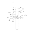
図1は、本発明に係る第1実施形態の軸体としてのシャフト10と軸上固定体としてのヨーク20を一体化した一体化部材1を示す断面図である。
図1に示すように、一体化部材1は、シャフト10を配置するための貫通孔21を有するヨーク20と、貫通孔21を貫通するように設けられ、ヨーク20の貫通孔21の内周面で外表面10aが押圧固定されるシャフト10と、を備えている。
(First embodiment)
FIG. 1 is a cross-sectional view showing an integrated
As shown in FIG. 1, the integrated
図1に示す一体化部材1は、インナーモータ用のロータに用いられる部材であり、後ほど説明するが、ヨーク20の外周面22上にプラスチックマグネット40(図示せず)が射出成形によって設けられてロータとなる。
An integrated
(シャフト)
シャフト10は、モータの軸受で回転可能に軸支され、ロータの回転軸となる部分であり、本実施形態では、ステンレス製のシャフト10を用いている。
図1に示すように、シャフト10は、外表面10aの周方向の全周に亘って第1の溝11が形成されており、この第1の溝11は、ヨーク20の一端20a側の内周面20aaが配置される部分となる。
(shaft)
The
As shown in FIG. 1, the
(ヨーク)
ヨーク20は、磁気回路を形成する部材であり、シャフト10との高い固定強度が得やすいことから磁性金属からなるものとすることが好適である。
(yoke)
The
本実施形態では、磁性金属で一体成形したヨーク20を用いており、例えば、磁性金属としては、不純物の少ない純鉄、炭素の低い低炭素鋼、珪素を含んだ珪素鉄及びフェライト系ステンレス鋼などを好適に用いることができる。
In this embodiment, a
ここで、シャフト10に対するヨーク20の固定位置は、設計段階で決まっているので、その設計を基にシャフト10には、ヨーク20の一端20a側の内周面20aaが第1の溝11の軸幅内に収まるように、第1の溝11が形成されている。
Here, since the fixing position of the
そして、図1に示すように、シャフト10との一体化に当たって、ヨーク20は、一端20a側の内周面20aaが第1の溝11の軸幅内に収まるように第1の溝11の周縁11aから第1の溝11側(第1の溝11の軸幅側)に突出するように設けられ、理由については後述するが、一端20a側の内周面20aaが、シャフト10の外表面10a(ヨーク20と接触している外表面10a)よりも第1の溝11の内径側に食い込むようにされる。
As shown in FIG. 1, when integrating with the
また、後ほど説明するが、ヨーク20の外周面22には、外周面22上に成形されるプラスチックマグネット40(図示せず)の固定強度を高めるための2つの溝23、24がシャフト10の軸方向(Z軸方向)で離間する位置に形成されている。
この2つの溝23、24は、ヨーク20の外周面22の全周に亘って溝幅及び溝深さが均一になるように形成されている。
このように、全周に亘って溝幅及び溝深さを均一にしておくことで、ロータにおける周方向の重量バランスを均一にすることができるようになる。
As will be described later, two
The two
Thus, by making the groove width and groove depth uniform over the entire circumference, the circumferential weight balance of the rotor can be made uniform.
(一体化部材の製造方法)
以下、このような一体化部材1の製造方法を説明しながら、更に一体化部材1についての詳細な説明を行う。
まず、外表面10aの周方向の全周に亘って形成された第1の溝11を有するシャフト10と、外周面22に2つの溝23、24が形成されるとともに中央にシャフト10の外径よりも少し小さい内径の貫通孔21が形成されたヨーク20と、を準備する。
(Manufacturing method of integrated member)
Hereinafter, while explaining the manufacturing method of such an
First, the
より具体的には、シャフト10は、溝形成工程によって、外径が均一な円柱状のシャフト基材の軸方向の所定の位置に外表面10aの周方向の全周に亘って第1の溝11を形成することで作製される。
なお、シャフト基材は外径が均一な円柱状でよいため、直線性及び長手方向の外径精度を高いものとし易く、それに溝を形成するだけであるため、溝が形成された後のシャフト10の状態でも直線性及び長手方向の外径精度が高いものとなる。
More specifically, the
In addition, since the shaft base material may be a columnar shape having a uniform outer diameter, it is easy to improve the linearity and the outer diameter accuracy in the longitudinal direction, and only the groove is formed thereon, so the shaft after the groove is formed. Even in the state of 10, the linearity and the outer diameter accuracy in the longitudinal direction are high.
このようにして作製されたシャフト10を、そのまま一体化部材1に用いるようにしてもよいが、作製したシャフト10に対して外表面10aをセンタレス研磨する研磨工程を行い、このセンタレス研磨を行ったシャフト10を一体化部材1に用いることが好ましい。
なお、センタレス研磨も極めて外径精度が高い状態を維持できる研磨方法のため、シャフト10にセンタレス研磨を施した後のシャフト10も高い直線性及び長手方向の外径精度を維持した状態となる。
The
In addition, since the centerless polishing is a polishing method capable of maintaining a state where the outer diameter accuracy is extremely high, the
さらに溝形成工程で形成された第1の溝11は、第1の溝11の周縁11aのエッジがRを帯びた、つまり、丸みのあるエッジになっている場合があるが、この丸みを帯びている部分をセンタレス研磨工程で削り取ることによって、第1の溝11の周縁11aが角張ったエッジのたった状態とすることができる。
Further, the
このようにエッジを立たせることが好ましい理由については、後述するが、研磨工程では、例えば、第1の溝11の周縁11aの角のR(フィレット)が0.10mm以下、より好ましくは0.05mm以下、更に好ましくは0.02mm以下となるように、センタレス研磨を実施する。
The reason why it is preferable to make the edge stand like this will be described later. In the polishing step, for example, the R (fillet) of the corner of the
シャフト10とヨーク20が準備できたら、次に、シャフト10とヨーク20を一体化するように焼き嵌めを行う固定工程を行う。
具体的には、ヨーク20を加熱して熱膨張させ、ヨーク20の貫通孔21を大きくし、シャフト10を貫通孔21に挿通しやすい状態にする。
After the
Specifically, the
そして、シャフト10を挿通しやすい状態となったところで貫通孔21にシャフト10を挿入していく。
このシャフト10の挿入は、ヨーク20の一端20a側の内周面20aaが第1の溝11の溝の幅内に収まるように、第1の溝11の周縁11aから第1の溝11側に突出するようにヨーク20を位置させた状態となるようにして、この状態を維持したまま、ヨーク20が冷えて収縮するのを待つ。
The
The
上述したように、ヨーク20の貫通孔21は、シャフト10の外表面10aの直径よりも少し小さい内径となるように形成されているため、ヨーク20が冷えて収縮すると、ヨーク20の貫通孔21の内周面が、シャフト10の外表面10aを強く押圧した状態となり、シャフト10とヨーク20が一体化される。
As described above, the through
さらに、ヨーク20の一端20a側の内周面20aaは、第1の溝11の溝の幅内に収まるように、第1の溝11の周縁11aから第1の溝11側に突出しているため、シャフト10の外表面10aで規制されることなく、このヨーク20の収縮時に、シャフト10の外表面10aよりも第1の溝11の内径側に食い込んだ状態となる。
Further, the inner peripheral surface 20aa on the one
このため、第1の溝11の周縁11aの部分では、ヨーク20の一端20a側の内周面20aaが第1の溝11側に食い込んだ状態となることによる段差ができるため(丸囲み部分A参照)、この段差が第1の溝11の側面に係合し、ヨーク20を一端20a側から他端20b側に押すような力がかかっても、ヨーク20がシャフト10上で滑るように移動することが抑制される。
For this reason, in the part of the
特に、上述したように、センタレス研磨を施して、第1の溝11の周縁11aの角のRを小さくし、周縁11aのエッジが立った状態にしておくと、鋭角な段差が形成されることになるため、丸みを帯びた段差の場合に比べてヨーク20がシャフト10上で滑るように移動することを、より効率よく抑制することができる。
In particular, as described above, when the centerless polishing is performed to reduce the corner R of the
ところで、ヨーク20の一端20a側の内周面20aaの食い込み量は、第1の溝11上に位置する内周面20aaのシャフト10の軸方向(Z軸方向)で見たときの幅が大きいほど多くなり、逆に幅が小さくなれば、食い込み量が少なくなり、ヨーク20がシャフト10から抜けたり、シャフト10上で軸方向(Z軸方向)にズレたりし易くなる。
By the way, the amount of biting of the inner peripheral surface 20aa on the one
このことから、第1の溝11の溝の幅内に位置する一端20a側の貫通孔21の内周面20aaは、シャフト10の軸方向(Z軸方向)で見た幅が0.2mm以上であることが好適である。
For this reason, the inner peripheral surface 20aa of the through
このようにしてシャフト10とヨーク20を一体化した一体化部材1には、さらに、ヨーク20の外周面22にプラスチックマグネット40(図示せず)を設けるマグネット成形工程が施され、ロータとされる。
In this way, the
(ロータの製造方法)
引き続き、簡単に一体化部材1にマグネット成形工程を施してロータを製造する製造方法について説明する。
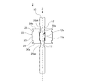
図2は、一体化部材1を用いたロータの製造方法を説明するための断面図である。
図2に示すように、一体化部材1を上金型31と下金型32とからなる金型内に配置する。
(Method for manufacturing rotor)
Next, a manufacturing method for manufacturing a rotor by simply applying a magnet forming process to the
FIG. 2 is a cross-sectional view for explaining a method for manufacturing a rotor using the
As shown in FIG. 2, the
金型は、ヨーク20の外周面22上にプラスチックマグネット40を成形するために、ヨーク20の外周面22に対応する部分にプラスチックマグネット40の材料を充填するための空間ができるように設計されており、この空間内に加熱することで流動性を高めたプラスチックマグネット40の材料が供給される。
In order to mold the
プラスチックマグネット40の材料は、一般的なものであれば、特に限定されるものではないが、ネオジウム系の磁性紛体やフェライト系の磁性紛体をナイロン(ポリアミド樹脂)などのプラスチックマグネット40のバインダーに用いられる熱可塑性樹脂に分散した材料を好適に用いることができる。
なお、本実施形態では、磁性紛体にネオジウム系の磁性紛体を用いたプラスチックマグネット40を用いている。
The material of the
In the present embodiment, the
この供給されるプラスチックマグネット40の材料は、流動性が高い状態になっているため、ヨーク20の溝23、24内にも充填される。
そして、材料の充填が終わった後、プラスチックマグネット40の材料が冷えて流動性が低くなり、固化する状態を待って、金型を取り外すと、ヨーク20の外周面22上にプラスチックマグネット40が成形されたロータの状態となる。
Since the material of the
Then, after the filling of the material is finished, the material of the
ここで、金型に供給されるプラスチックマグネット40の材料は、加熱されているため、材料の体積として見ると熱膨張した状態にある。
このため、冷えていく過程でヨーク20の外周面22を強く押圧するように径方向にプラスチックマグネット40は収縮し、ヨーク20に一体化した状態となるが、この収縮は、径方向だけでなく、シャフト10の軸方向(Z軸方向)にも起こる。
Here, since the material of the
For this reason, in the process of cooling, the
そうすると、2つの溝23、24内に充填されたプラスチックマグネット40の部分が溝23、24の内側の側壁23a、24aを強く挟み込むようになるので、プラスチックマグネット40とヨーク20の間の密着力が増し、プラスチックマグネット40をヨーク20に対してより一層強固に固定することができる。
As a result, the portions of the
また、このように2つの溝23、24内にプラスチックマグネット40を食い込ませた構造としておくと、モータ駆動時の熱でプラスチックマグネット40が熱膨張したときには、溝23、24の内側の側壁23a、24aと反対側に位置する溝23、24の外側の側壁を、溝23、24内に食い込んでいるプラスチックマグネット40の部分が押圧するようになり、高温状態においてもプラスチックマグネット40をヨーク20に対して強固に固定した状態を維持することができる。
In addition, when the
したがって、低温から高温までの広い温度域において、プラスチックマグネット40をヨーク20に対して強固に固定することができるので、プラスチックマグネット40がヨーク20の周方向に回転するようにズレることを抑制することができる。
Therefore, since the
また、溝23、24内にプラスチックマグネット40が食い込むようになっているため、プラスチックマグネット40がシャフト10の軸方向(Z軸方向)にズレたり、ヨーク20から抜けたりすることも防止される。
なお、溝23、24の溝深さが深い方が固定強度を高めることができるので、溝深さは0.5mm以上であることが好適である。
Further, since the
In addition, since the fixing strength can be increased when the groove depth of the
(第2実施形態)
次に、本発明に係る第2実施形態の一体化部材2について説明する。
なお、第2実施形態の一体化部材2において、第1実施形態の一体化部材1と同様の構成部分については、説明を省略する場合がある。
(Second Embodiment)
Next, the
In the
図3は、本発明に係る第2実施形態の一体化部材2を示す断面図である。
図3に示すように、第2実施形態のシャフト10は、第1実施形態で説明した第1の溝11に加えて、外表面10aの周方向の全周に亘って形成され、シャフト10の軸方向(Z軸方向)の位置で第1の溝11と離間する位置に設けられた第2の溝12を有している。
FIG. 3 is a cross-sectional view showing the
As shown in FIG. 3, the
そして、ヨーク20は、他端20b側の内周面20bbが第2の溝12の軸幅内に収まるように第2の溝12の周縁12aから第2の溝12側(第2の溝12の軸幅側)に突出するように設けられており、他端20b側の内周面20bbが、シャフト10の外表面10aよりも第2の溝12の内径側に食い込むようにされている。
Then, the
このようにすることによって、第1実施形態で説明した周縁11aのところにできる段差による係合構造が、周縁12aのところにも形成されることになるのでヨーク20を他端20b側から一端20a側に押すような力がヨーク20に加わったとしてもヨーク20がズレたり、抜けたりすることが防止される。
By doing in this way, the engagement structure by the level | step difference made in the
したがって、第2実施形態の一体化部材2であれば、ヨーク20に対してシャフト10の軸方向(Z軸方向)に沿った力が、ヨーク20の一端20a側に向かって加わる場合でも、他端20b側に向かって加わる場合でもヨーク20がズレたり、抜けたりすることを防止することができる。
Therefore, in the case of the
なお、この第2の溝12側の構成も第1実施形態で説明した第1の溝11と同様であることが好ましい。
したがって、第2の溝12の溝の幅内に位置する他端20b側の内周面20bbは、シャフト10の軸方向で見た幅が0.2mm以上であることが好ましく、また、第2の溝12のヨーク20の内周面に接触する周縁12aの角のR(フィレット)は0.10mm以下、より好ましくは0.05mm以下、更に好ましくは0.02mm以下であることがよい。
The configuration on the
Therefore, it is preferable that the inner peripheral surface 20bb on the
このような周縁12aの角のRはセンタレス研磨を行うことで作ることができ、第1の溝11と第2の溝12を形成したシャフト10に対してセンタレス研磨を行う研磨工程を実施すればよい。
The corner R of the
また、第2実施形態の一体化部材2を製造するためには、シャフト10を準備するに当たって、第1実施形態で説明した溝形成工程に、シャフト10の軸方向(Z軸方向)の位置で第1の溝11と離間する位置の外表面10aの周方向の全周に亘って第2の溝12を形成することを加えるようにし、そして、焼き嵌めを行う固定工程では、ヨーク20の他端20b側の内周面20bbを第2の溝12の溝の幅内に収まるように第2の溝12の周縁12aから第2の溝12側に突出するように、ヨーク20を位置させるようにして焼き嵌めを行うようにすればよい。
Moreover, in order to manufacture the
なお、シャフト10に対して第1の溝11と第2の溝12を設け、ヨーク20の両端(一端20a及び他端20b)側を溝に食い込ませるようにするときに、一端20a側の内周面20aaと他端20b側の内周面20bbを同じ幅だけ溝の軸幅側に突出させるようにすれば、食い込みの状態が両端(一端20a及び他端20b)で同じになるので、ヨーク20にかかるシャフト10の軸方向に沿った力に対する耐久力を両端(一端20a及び他端20b)でほぼ同じにすることができる。
When the
したがって、両端(一端20a及び他端20b)のシャフト10の軸方向に沿った力に対する耐久力を等しくすることが求められる場合には、一端20a側の内周面20aa及び他端20b側の内周面20bbの溝の軸幅側に突出させる幅を等しくしておけばよい。
Accordingly, when it is required to equalize the durability against the force along the axial direction of the
以上、本発明を実施形態に基づき説明したが、本発明は実施形態に限定されるものではなく、その要旨を逸脱しない範囲で種々変更が可能である。
上記実施形態では、軸体がシャフト10であり、軸上固定体がヨーク20であるモータのロータに用いられる一体化部材1、2について説明してきたが、本発明に係る一体化部材はモータのロータに用いられる一体化部材に限定されるものではない。
As mentioned above, although this invention was demonstrated based on embodiment, this invention is not limited to embodiment, A various change is possible in the range which does not deviate from the summary.
In the above embodiment, the
例えば、動力を伝達するギヤ部材などの場合でも、回転軸となる軸体に軸上固定体としてのギヤ部品が固定されたものなどがあり、本発明に係る一体化部材は、そのようなギヤ部材のようなものであってもよい。
したがって、本発明に係る一体化部材は、軸体と軸体上に軸上固定体となる部品が固定される態様の部材一般を含むものである。
For example, even in the case of a gear member that transmits power, there is one in which a gear part as an on-axis fixed body is fixed to a shaft body that is a rotating shaft, and the integrated member according to the present invention is such a gear. It may be a member.
Therefore, the integrated member which concerns on this invention contains the member in general of the aspect by which the components used as an axial fixed body are fixed on a shaft body and a shaft body.
また、上記実施形態では、シャフト10上に設けられる溝が第1の溝11だけ(第1実施形態)又は第1の溝11及び第2の溝12だけ(第2実施形態)の場合について示したが、例えば、シャフト10の端部にモータに取付ける際に必要な外周溝などを設けてよいことは言うまでもない。
Moreover, in the said embodiment, it shows about the case where the groove | channel provided on the
このように、本発明は、上記実施形態に限定されるものではなく、そのことは当業者にとって特許請求の範囲の記載から明らかである。 As described above, the present invention is not limited to the above-described embodiments, and this will be apparent to those skilled in the art from the claims.
1,2…一体化部材、10…シャフト(軸体)、10a…外表面、11…第1の溝、11a…周縁、12…第2の溝、12a…周縁、20…ヨーク(軸上固定体)、20a…一端、20aa…一端側の内周面、20b…他端、20bb…他端側の内周面、21…貫通孔、22…外周面、23…溝、24…溝、40…プラスチックマグネット
DESCRIPTION OF
Claims (9)
貫通孔を有する前記軸上固定体と、
前記貫通孔を貫通するように設けられ、前記軸上固定体の前記貫通孔の内周面で、外表面が押圧固定される前記軸体と、を備え、
前記軸体が前記外表面の周方向の全周に形成された第1の溝を有し、
前記軸上固定体は、一端側の前記内周面が前記第1の溝の幅内に収まるように前記第1の溝の周縁から前記第1の溝の軸幅側に突出するように設けられており、
一端側に突出した前記内周面が、前記軸体の前記外表面よりも前記第1の溝の内径側に食い込んでいることを特徴とする一体化部材。 An integrated member that integrates the shaft body and the on-axis fixed body,
The on-axis fixed body having a through hole;
The shaft body, which is provided so as to penetrate the through hole, and whose outer surface is pressed and fixed at the inner peripheral surface of the through hole of the on-axis fixed body,
The shaft body has a first groove formed on the entire circumference of the outer surface in the circumferential direction;
The on-axis fixed body is provided so as to protrude from the peripheral edge of the first groove to the axial width side of the first groove so that the inner peripheral surface on one end side is within the width of the first groove. And
The integrated member characterized in that the inner peripheral surface protruding toward one end bites into the inner diameter side of the first groove with respect to the outer surface of the shaft body.
前記軸上固定体は、他端側の前記内周面が前記第2の溝の幅内に収まるように前記第2の溝の周縁から前記第2の溝の軸幅側に突出するように設けられており、
他端側の前記内周面が、前記軸体の前記外表面よりも前記第2の溝の内径側に食い込んでいることを特徴とする請求項1に記載の一体化部材。 The shaft body has a second groove formed on the entire circumference of the outer surface at a position separated from the first groove;
The on-axis fixed body projects from the peripheral edge of the second groove to the axial width side of the second groove so that the inner peripheral surface on the other end side is within the width of the second groove. Provided,
The integrated member according to claim 1, wherein the inner peripheral surface on the other end side bites into an inner diameter side of the second groove with respect to the outer surface of the shaft body.
前記一体化部材の軸上固定体がヨークとされ、
前記ヨークの外周面に固定されたマグネットを備えることを特徴とするロータ。 An integrated member according to any one of claims 1 to 5,
The on-axis fixed body of the integrated member is a yoke,
A rotor comprising a magnet fixed to the outer peripheral surface of the yoke.
少なくとも第1の溝を前記軸体の外表面の全周に形成する溝形成工程と、
前記軸上固定体の貫通孔に貫通した状態で前記軸上固定体の貫通孔の内周面で前記軸体の前記外表面が押圧固定されるように焼き嵌めを行う固定工程と、を含み、
前記焼き嵌めは、前記軸上固定体の一端側の前記内周面が前記第1の溝の軸幅内に収まるように前記第1の溝の周縁から前記第1の溝の軸幅側に突出するように前記軸上固定体を位置させて行われることを特徴とする一体化部材の製造方法。 A manufacturing method of an integrated member in which a shaft body and an on-axis fixed body are integrated,
A groove forming step of forming at least the first groove on the entire circumference of the outer surface of the shaft body;
A fixing step of performing shrink fitting so that the outer surface of the shaft body is pressed and fixed on the inner peripheral surface of the through hole of the on-axis fixed body in a state of passing through the through-hole of the on-axis fixed body. ,
The shrink fitting is performed from the peripheral edge of the first groove to the axial width side of the first groove so that the inner peripheral surface on one end side of the on-axis fixed body is within the axial width of the first groove. A method for producing an integrated member, wherein the on-axis fixed body is positioned so as to protrude.
前記焼き嵌めは、前記軸上固定体の他端側の前記内周面が前記第2の溝の軸幅内に収まるように前記第2の溝の周縁から前記第2の溝の軸幅側に突出するように前記軸上固定体を位置させて行われることを特徴とする請求項7に記載の一体化部材の製造方法。 The groove forming step includes forming a second groove on the entire circumference in the circumferential direction of the outer surface at a position separated from the first groove at a position in the axial direction of the shaft body,
The shrink-fitting is performed from the peripheral edge of the second groove to the axial width side of the second groove so that the inner peripheral surface on the other end side of the on-axis fixed body is within the axial width of the second groove. The method for producing an integrated member according to claim 7, wherein the on-axis fixed body is positioned so as to protrude to the center.
前記研磨工程が、前記溝形成工程の後であって前記固定工程の前に行われることを特徴とする請求項8に記載の一体化部材の製造方法。
Centerless polishing of the outer surface of the shaft body so that at least the corner fillet at the periphery of the first groove and the second groove in contact with the inner peripheral surface of the fixed body on the shaft is 0.05 mm or less. A polishing step to
The method for manufacturing an integrated member according to claim 8, wherein the polishing step is performed after the groove forming step and before the fixing step.
Priority Applications (1)
| Application Number | Priority Date | Filing Date | Title |
|---|---|---|---|
| JP2016000711A JP2017123712A (en) | 2016-01-05 | 2016-01-05 | Integrated member in which shaft body and on-axis fixed body are integrated, and manufacturing method of integrated member in which shaft body and on-axis fixed body are integrated |
Applications Claiming Priority (1)
| Application Number | Priority Date | Filing Date | Title |
|---|---|---|---|
| JP2016000711A JP2017123712A (en) | 2016-01-05 | 2016-01-05 | Integrated member in which shaft body and on-axis fixed body are integrated, and manufacturing method of integrated member in which shaft body and on-axis fixed body are integrated |
Publications (1)
| Publication Number | Publication Date |
|---|---|
| JP2017123712A true JP2017123712A (en) | 2017-07-13 |
Family
ID=59306033
Family Applications (1)
| Application Number | Title | Priority Date | Filing Date |
|---|---|---|---|
| JP2016000711A Pending JP2017123712A (en) | 2016-01-05 | 2016-01-05 | Integrated member in which shaft body and on-axis fixed body are integrated, and manufacturing method of integrated member in which shaft body and on-axis fixed body are integrated |
Country Status (1)
| Country | Link |
|---|---|
| JP (1) | JP2017123712A (en) |
Cited By (1)
| Publication number | Priority date | Publication date | Assignee | Title |
|---|---|---|---|---|
| JP2021027799A (en) * | 2019-08-07 | 2021-02-22 | アイシン・エィ・ダブリュ株式会社 | Rotor and rotor manufacturing method |
-
2016
- 2016-01-05 JP JP2016000711A patent/JP2017123712A/en active Pending
Cited By (1)
| Publication number | Priority date | Publication date | Assignee | Title |
|---|---|---|---|---|
| JP2021027799A (en) * | 2019-08-07 | 2021-02-22 | アイシン・エィ・ダブリュ株式会社 | Rotor and rotor manufacturing method |
Similar Documents
| Publication | Publication Date | Title |
|---|---|---|
| JP4803525B2 (en) | Brushless motor rotor and brushless motor | |
| US9634533B2 (en) | Motor with a stator having four separate corner bobbins/insulators and molded resin insulation around tooth completely enclosing the coil and manufacturing method thereof | |
| JP5746873B2 (en) | Manufacturing method of rotor | |
| WO2012137464A1 (en) | Rotor unit, rotating electrical machine, and method for manufacturing rotor unit | |
| JP7053129B2 (en) | Rotor assembly with permanent magnets and its manufacturing method | |
| JP2015154515A (en) | Method for molding motor and resin casing | |
| US7911099B2 (en) | Outer rotor motor | |
| JP2019106797A (en) | Rotor manufacturing method | |
| CN110729832A (en) | Rotor unit | |
| JP2009273356A (en) | Method for manufacturing stator housing of electric motor | |
| CN103460569A (en) | Bonded magnet rotor, manufacturing method thereof, and motor having the bonded magnet rotor | |
| JP2017123712A (en) | Integrated member in which shaft body and on-axis fixed body are integrated, and manufacturing method of integrated member in which shaft body and on-axis fixed body are integrated | |
| CN206370738U (en) | Motor case, motor and vehicle | |
| JP2012239319A (en) | Rotor for stepping motor and hb stepping motor | |
| JP2008061319A (en) | Stator, stator manufacturing method and inner ring | |
| JPWO2018016177A1 (en) | Motor manufacturing method, motor manufacturing apparatus, resin sealing jig and motor | |
| JP6545383B2 (en) | Rotor, motor, air conditioner, and method of manufacturing rotor | |
| JPH1127912A (en) | Electric motor manufacturing method | |
| JP2017123711A (en) | Rotor and motor using the rotor | |
| US7714476B2 (en) | Rotating electrical machine core and rotating electrical machine | |
| JP2017118772A (en) | Motor, and manufacturing method of rotor constituting motor | |
| WO2018016067A1 (en) | Electric motor, air conditioner, rotor, and method of manufacturing electric motor | |
| JP5103000B2 (en) | Magnet molding method of rotor core and jig therefor | |
| JP4876364B2 (en) | Manufacturing method of motor | |
| EP2747248B1 (en) | Magnetic rotor unit |