JP2017123588A - Color processing apparatus, image formation device, and image formation system - Google Patents
Color processing apparatus, image formation device, and image formation system Download PDFInfo
- Publication number
- JP2017123588A JP2017123588A JP2016002282A JP2016002282A JP2017123588A JP 2017123588 A JP2017123588 A JP 2017123588A JP 2016002282 A JP2016002282 A JP 2016002282A JP 2016002282 A JP2016002282 A JP 2016002282A JP 2017123588 A JP2017123588 A JP 2017123588A
- Authority
- JP
- Japan
- Prior art keywords
- color
- image
- data
- unit
- image forming
- Prior art date
- Legal status (The legal status is an assumption and is not a legal conclusion. Google has not performed a legal analysis and makes no representation as to the accuracy of the status listed.)
- Pending
Links
Images


Classifications
-
- H—ELECTRICITY
- H04—ELECTRIC COMMUNICATION TECHNIQUE
- H04N—PICTORIAL COMMUNICATION, e.g. TELEVISION
- H04N1/00—Scanning, transmission or reproduction of documents or the like, e.g. facsimile transmission; Details thereof
- H04N1/46—Colour picture communication systems
- H04N1/56—Processing of colour picture signals
- H04N1/60—Colour correction or control
- H04N1/603—Colour correction or control controlled by characteristics of the picture signal generator or the picture reproducer
- H04N1/6052—Matching two or more picture signal generators or two or more picture reproducers
- H04N1/6055—Matching two or more picture signal generators or two or more picture reproducers using test pattern analysis
-
- G—PHYSICS
- G06—COMPUTING; CALCULATING OR COUNTING
- G06K—GRAPHICAL DATA READING; PRESENTATION OF DATA; RECORD CARRIERS; HANDLING RECORD CARRIERS
- G06K15/00—Arrangements for producing a permanent visual presentation of the output data, e.g. computer output printers
- G06K15/02—Arrangements for producing a permanent visual presentation of the output data, e.g. computer output printers using printers
- G06K15/18—Conditioning data for presenting it to the physical printing elements
- G06K15/1835—Transforming generic data
- G06K15/1836—Rasterization
-
- G—PHYSICS
- G06—COMPUTING; CALCULATING OR COUNTING
- G06K—GRAPHICAL DATA READING; PRESENTATION OF DATA; RECORD CARRIERS; HANDLING RECORD CARRIERS
- G06K15/00—Arrangements for producing a permanent visual presentation of the output data, e.g. computer output printers
- G06K15/02—Arrangements for producing a permanent visual presentation of the output data, e.g. computer output printers using printers
- G06K15/18—Conditioning data for presenting it to the physical printing elements
- G06K15/1867—Post-processing of the composed and rasterized print image
- G06K15/1872—Image enhancement
- G06K15/1878—Adjusting colours
- G06K15/188—Adjusting colours with provisions for treating some of the print data differently
-
- H—ELECTRICITY
- H04—ELECTRIC COMMUNICATION TECHNIQUE
- H04N—PICTORIAL COMMUNICATION, e.g. TELEVISION
- H04N1/00—Scanning, transmission or reproduction of documents or the like, e.g. facsimile transmission; Details thereof
- H04N1/387—Composing, repositioning or otherwise geometrically modifying originals
- H04N1/3877—Image rotation
- H04N1/3878—Skew detection or correction
-
- H—ELECTRICITY
- H04—ELECTRIC COMMUNICATION TECHNIQUE
- H04N—PICTORIAL COMMUNICATION, e.g. TELEVISION
- H04N1/00—Scanning, transmission or reproduction of documents or the like, e.g. facsimile transmission; Details thereof
- H04N1/40—Picture signal circuits
- H04N1/405—Halftoning, i.e. converting the picture signal of a continuous-tone original into a corresponding signal showing only two levels
-
- H—ELECTRICITY
- H04—ELECTRIC COMMUNICATION TECHNIQUE
- H04N—PICTORIAL COMMUNICATION, e.g. TELEVISION
- H04N1/00—Scanning, transmission or reproduction of documents or the like, e.g. facsimile transmission; Details thereof
- H04N1/46—Colour picture communication systems
- H04N1/56—Processing of colour picture signals
- H04N1/60—Colour correction or control
- H04N1/6002—Corrections within particular colour systems
- H04N1/6008—Corrections within particular colour systems with primary colour signals, e.g. RGB or CMY(K)
-
- H—ELECTRICITY
- H04—ELECTRIC COMMUNICATION TECHNIQUE
- H04N—PICTORIAL COMMUNICATION, e.g. TELEVISION
- H04N2201/00—Indexing scheme relating to scanning, transmission or reproduction of documents or the like, and to details thereof
- H04N2201/0077—Types of the still picture apparatus
- H04N2201/0091—Digital copier; digital 'photocopier'
Landscapes
- Engineering & Computer Science (AREA)
- Multimedia (AREA)
- Signal Processing (AREA)
- General Engineering & Computer Science (AREA)
- Physics & Mathematics (AREA)
- General Physics & Mathematics (AREA)
- Theoretical Computer Science (AREA)
- Color Image Communication Systems (AREA)
- Facsimile Image Signal Circuits (AREA)
- Image Processing (AREA)
- Color, Gradation (AREA)
Abstract
Description
本発明は、色処理装置、画像形成装置、画像形成システムに関する。 The present invention relates to a color processing apparatus, an image forming apparatus, and an image forming system.
近年の印刷市場は、オフセット印刷機からオンデマンド・デジタル印刷機への移行が徐々に加速している。オンデマンド・プリンタの使用ケースの1つとして増刷がある。そしてオフセット印刷機で大量部数を印刷した後にオンデマンド・プリンタで少部数だけ増刷するケースや、オフセット印刷機を使用せずにオンデマンド・プリンタだけで増刷するケースがある。
このような増刷時に、過去に出力した印刷物と増刷時の印刷物の色を合わせるためには、過去に印刷したカラ―パッチを測色して色変換プロファイルを作成したり、過去のプリント出力条件(色変換プロファイルの設定など)と同一条件にして出力することが必要となる。
In the recent printing market, the shift from offset printing machines to on-demand digital printing machines has been gradually accelerating. One of the use cases of on-demand printers is reprinting. There are cases where a large number of copies are printed by an offset printing machine and then printed by a small number of copies by an on-demand printer, or cases where only an on-demand printer is used without using an offset printing machine.
In order to match the color of the printed matter output in the past and the printed matter at the time of extra printing at the time of such reprinting, color conversion profiles can be created by measuring color patches printed in the past, or past print output conditions ( It is necessary to output under the same conditions as the color conversion profile setting.
特許文献1には、第一の出力画像データと原稿画像データの位置あわせ、第二の出力画像データと原稿画像データの位置あわせをそれぞれ行う位置合わせ手段と、第一の色成分値対応付けデータ、及び、第二の色成分値対応付けデータをそれぞれ生成する色成分値対応付け手段と、色調を変換するための色調変換パラメータを生成する色調変換パラメータ決定手段と、色調変換パラメータにより原稿画像データの画素値を変換する色調変換手段と、を有する画像処理装置が開示されている。
また特許文献2には、原稿画像データ、第一の出力画像データ、又は、第二の出力画像データの少なくとも1つを部分領域に分割する部分領域分割手段と、部分領域毎に第一の出力画像データと原稿画像データの対応する画素の色成分値が対応づけられた第一の色成分値対応付けデータ、及び、第二の色成分値対応付けデータをそれぞれ生成する色成分値対応付け手段と、第一の出力画像データと第二の出力画像データの画素値が同程度になる、部分領域毎の原稿画像データの画素値の組から、部分領域毎に色調を変換するための色調変換パラメータを生成する色調変換パラメータ決定手段と、色調変換パラメータにより部分領域毎に前記原稿画像データの画素値を変換する色調変換手段と、を有することを特徴とする画像処理装置が開示されている。
Japanese Patent Application Laid-Open No. 2004-151867 discloses alignment means for performing alignment between first output image data and document image data, alignment between second output image data and document image data, and first color component value association data. And color component value associating means for generating second color component value associating data, color tone conversion parameter determining means for generating a tone conversion parameter for converting the tone, and original image data by the tone conversion parameter An image processing apparatus having a color tone converting means for converting the pixel value of the image is disclosed.
Further,
本発明は、例えば、第1の画像形成手段から出力された印刷物の色に合わせ、第2の画像形成手段で印刷物を出力するときに、印刷物を出力する際に使用する画像データと第1の画像形成手段から出力された印刷物の色データとの位置ずれを抑制することを目的とする。 In the present invention, for example, when a printed material is output by the second image forming unit according to the color of the printed material output from the first image forming unit, the image data used when the printed material is output and the first data It is an object of the present invention to suppress positional deviation from color data of a printed matter output from an image forming unit.
請求項1に記載の発明は、画像データを基に第1の画像形成手段により出力された第1の画像の色データを取得する色データ取得部と、前記画像データの色のばらつきを取得するばらつき取得部と、色のばらつきがより大きい領域において前記画像データと前記色データとの間の位置ずれ量を取得する位置ずれ取得部と、位置ずれを合わせた上で、色のばらつきがより小さい領域において前記画像データと前記色データとの対応関係である第1の対応関係を作成する第1の対応関係作成部と、前記第1の対応関係、および当該第1の対応関係に対応する第2の画像形成手段についての第2の対応関係から、当該画像データを基に当該第2の画像形成手段により出力される第2の画像の色が前記第1の画像の色になるように、当該第2の画像形成手段の色調整を行う変換関係を作成する変換関係作成部と、を備えることを特徴とする色処理装置である。
請求項2に記載の発明は、前記位置ずれ取得部は、色のばらつきがより大きい領域における前記画像データと前記色データとの間の位置ずれ量から、色のばらつきがより小さい領域における当該画像データと当該色データとの間の位置ずれ量を推定することを特徴とする請求項1に記載の色処理装置である。
請求項3に記載の発明は、前記位置ずれ取得部は、色のばらつきがより大きい領域における前記画像データと前記色データとの間の平行移動量から、色のばらつきがより小さい領域における当該画像データと当該色データとの間の平行移動量、拡大縮小率および回転角を推定することを特徴とする請求項1に記載の色処理装置である。
請求項4に記載の発明は、前記位置ずれ取得部は、色のばらつきがより大きい領域における平行移動量のうち異常値を除いた平行移動量の総和を用いてアフィン変換係数を算出し、当該アフィン変換係数を基に色のばらつきがより小さい領域における前記画像データと前記色データとの間の平行移動量、拡大縮小率および回転角を推定することを特徴とする請求項3に記載の色処理装置である。
請求項5に記載の発明は、前記第1の対応関係は、予め用意しておいた第1の対応関係候補に対して、前記画像データと取得した前記色データとを当てはめ整合させることで作成されることを特徴とする請求項1乃至4の何れか1項に記載の色処理装置である。
請求項6に記載の発明は、画像データを基に第1の画像形成手段により出力された第1の画像の色データを取得する色データ取得部と、前記画像データの色のばらつきの程度を取得するばらつき取得部と、色のばらつきがより大きい領域における前記画像データと前記色データとの間の位置ずれを取得するとともに、取得した位置ずれ量から色のばらつきがより小さい領域における当該画像データと当該色データとの間の位置ずれ量を推定する位置ずれ取得部と、を備えることを特徴とする色処理装置である。
請求項7に記載の発明は、画像データを基に記録材に画像を形成する第2の画像形成手段と、前記第2の画像形成手段で形成される画像の色調整を行う色調整手段と、前記色調整手段で色調整を行うために使用される変換関係を作成する変換関係作成手段と、を備え、前記変換関係作成手段は、前記画像データを基に第1の画像形成手段により出力された第1の画像の色データを取得する色データ取得部と、前記画像データの色のばらつきを取得するばらつき取得部と、色のばらつきがより大きい領域において前記画像データと前記色データとの間の位置ずれ量を取得する位置ずれ取得部と、前記位置ずれ量を基に前記画像データと前記色データとの間の位置ずれを合わせる位置合わせ部と、位置ずれを合わせた上で、色のばらつきがより小さい領域において前記画像データと前記色データとの対応関係である第1の対応関係を作成する第1の対応関係作成部と、前記第1の対応関係、および当該第1の対応関係に対応する前記第2の画像形成手段についての第2の対応関係から、当該画像データを基に当該第2の画像形成手段により出力される第2の画像の色が前記第1の画像の色になるように、当該第2の画像形成手段の色調整を行う変換関係を作成する変換関係作成部と、を備えることを特徴とする画像形成装置である。
請求項8に記載の発明は、画像データを基に記録材に画像を形成する第1の画像形成手段および第2の画像形成手段と、前記第2の画像形成手段で形成される画像の色調整を行う色調整手段と、前記色調整手段で色調整を行うために使用される変換関係を作成する変換関係作成手段と、を備え、前記変換関係作成手段は、前記画像データを基に前記第1の画像形成手段により出力された第1の画像の色データを取得する色データ取得部と、前記画像データの色のばらつきを取得するばらつき取得部と、色のばらつきがより大きい領域において前記画像データと前記色データとの間の位置ずれ量を取得する位置ずれ取得部と、前記位置ずれ量を基に前記画像データと前記色データとの間の位置ずれを合わせる位置合わせ部と、位置ずれを合わせた上で、色のばらつきがより小さい領域において前記画像データと前記色データとの対応関係である第1の対応関係を作成する第1の対応関係作成部と、前記第1の対応関係、および当該第1の対応関係に対応する前記第2の画像形成手段についての第2の対応関係から、当該画像データを基に当該第2の画像形成手段により出力される第2の画像の色が前記第1の画像の色になるように、当該第2の画像形成手段の色調整を行う変換関係を作成する変換関係作成部と、を備えることを特徴とする画像形成システムである。
According to the first aspect of the present invention, the color data acquisition unit that acquires the color data of the first image output by the first image forming unit based on the image data, and the color variation of the image data are acquired. A variation acquisition unit, a misregistration acquisition unit that acquires a misregistration amount between the image data and the color data in an area where the color variation is larger, and a color variation is smaller after combining the misregistration A first correspondence relation creating unit that creates a first correspondence relation that is a correspondence relation between the image data and the color data in the region; a first correspondence relation; and a first correspondence relation that corresponds to the first correspondence relation. From the second correspondence relationship of the second image forming unit, the color of the second image output by the second image forming unit based on the image data becomes the color of the first image. The second image form A conversion relationship creation unit that creates a conversion relationship for performing color adjustment means, a color processing apparatus comprising: a.
According to a second aspect of the present invention, the misregistration acquisition unit is configured to detect the image in the region where the color variation is smaller from the misregistration amount between the image data and the color data in the region where the color variation is larger. The color processing apparatus according to
According to a third aspect of the present invention, the misregistration acquisition unit is configured to detect the image in the region where the color variation is smaller from the amount of parallel movement between the image data and the color data in the region where the color variation is larger. The color processing apparatus according to
According to a fourth aspect of the present invention, the misregistration acquisition unit calculates an affine transformation coefficient using a total sum of parallel movement amounts excluding abnormal values among parallel movement amounts in a region where color variation is larger. 4. The color according to
According to a fifth aspect of the present invention, the first correspondence relationship is created by fitting and matching the image data and the acquired color data with a first correspondence relationship candidate prepared in advance. The color processing apparatus according to
According to a sixth aspect of the present invention, a color data acquisition unit that acquires the color data of the first image output by the first image forming unit based on the image data, and the degree of color variation of the image data are obtained. Obtaining a positional deviation between the image data and the color data in a region having a larger color variation and a variation obtaining unit to obtain the image data in a region having a smaller color variation from the obtained positional deviation amount And a misregistration acquisition unit that estimates a misregistration amount between the color data and the color data.
According to a seventh aspect of the present invention, there is provided a second image forming unit that forms an image on a recording material based on image data, and a color adjusting unit that performs color adjustment of an image formed by the second image forming unit. Conversion relation creating means for creating a conversion relation used for color adjustment by the color adjusting means, and the conversion relation creating means is output by the first image forming means based on the image data A color data acquisition unit that acquires color data of the first image that has been obtained, a variation acquisition unit that acquires color variation of the image data, and the image data and the color data in a region where the color variation is larger A position shift acquisition unit that acquires a position shift amount between, a position adjustment unit that matches a position shift between the image data and the color data based on the position shift amount, Less variation Corresponding to the first correspondence relationship, the first correspondence relationship, and the first correspondence relationship. The first correspondence relationship creating unit creates a first correspondence relationship that is a correspondence relationship between the image data and the color data. Based on the second correspondence relationship with respect to the second image forming unit, the color of the second image output by the second image forming unit based on the image data becomes the color of the first image. The image forming apparatus further includes a conversion relationship creating unit that creates a conversion relationship for performing color adjustment of the second image forming unit.
According to an eighth aspect of the present invention, there is provided a first image forming unit and a second image forming unit that form an image on a recording material based on image data, and a color of an image formed by the second image forming unit. A color adjustment unit that performs adjustment, and a conversion relationship creation unit that creates a conversion relationship used to perform color adjustment in the color adjustment unit, and the conversion relationship creation unit includes the conversion data based on the image data. A color data acquisition unit that acquires color data of the first image output by the first image forming unit; a variation acquisition unit that acquires color variation of the image data; A misregistration acquisition unit that acquires a misregistration amount between the image data and the color data, a registration unit that matches misregistration between the image data and the color data based on the misregistration amount, and a position Adjust the gap In the above, a first correspondence creating unit that creates a first correspondence that is a correspondence between the image data and the color data in an area where color variation is smaller, the first correspondence, and From the second correspondence relationship for the second image forming means corresponding to the first correspondence relationship, the color of the second image output by the second image forming means based on the image data is the first correspondence relationship. A conversion relationship creating unit that creates a conversion relationship for performing color adjustment of the second image forming unit so as to obtain the color of one image.
請求項1の発明によれば、印刷物を出力する際に使用する画像データと第1の画像形成手段から出力された印刷物の色データとの位置ずれを抑制することができる色処理装置を提供することができる。
請求項2の発明によれば、色のばらつきが小さい領域における位置合わせの精度が向上する。
請求項3の発明によれば、色のばらつきが小さい領域における位置合わせの精度がさらに向上する。
請求項4の発明によれば、色のばらつきが小さい領域における位置ずれを精度よく求めることができる。
請求項5の発明によれば、第1の画像形成手段から出力された印刷物の色を望む色に合わせるための変換関係を作成するにあたって、一部の色域に偏った色データや少ない色データしか得られない場合であっても、広い色域に対する対応関係を用いてこれを作成することを可能にする。
請求項6の発明によれば、印刷物を出力する際に使用する画像データと第1の画像形成手段から出力された印刷物の色データとの位置ずれを抑制することができる色処理装置を提供することができる。
請求項7の発明によれば、ユーザが専門的なスキルを備えていなくても色調整を行うことができる画像形成装置を提供することができる。
請求項8の発明によれば、ユーザが専門的なスキルを備えていなくても色調整を行うことができる画像形成システムを提供することができる。
According to the first aspect of the present invention, there is provided a color processing apparatus capable of suppressing the positional deviation between the image data used when outputting the printed matter and the color data of the printed matter output from the first image forming means. be able to.
According to the second aspect of the invention, the alignment accuracy in the region where the color variation is small is improved.
According to the third aspect of the present invention, the alignment accuracy in the region where the color variation is small is further improved.
According to the fourth aspect of the present invention, it is possible to accurately obtain the positional deviation in the region where the color variation is small.
According to the invention of
According to the sixth aspect of the present invention, there is provided a color processing apparatus capable of suppressing the positional deviation between the image data used when outputting the printed matter and the color data of the printed matter output from the first image forming means. be able to.
According to the seventh aspect of the present invention, it is possible to provide an image forming apparatus that can perform color adjustment even if the user does not have specialized skills.
According to the invention of
<画像形成システムの全体構成の説明>
以下、添付図面を参照して、本発明の実施の形態について詳細に説明する。
図1は、本実施の形態に係る画像形成システムの全体構成の一例を示す図である。
図示する画像形成システムSは、画像形成装置1と、画像形成装置2とを備える。
画像形成装置1および画像形成装置2は、詳しくは後述するが、画像データを基に用紙(記録材)に画像を形成する印刷機構部であり、少なくとも1種類の色材を用いて用紙に画像を形成する。この画像データは、例えば、ユーザから送信された印刷ジョブの画像についてのものである。
画像形成装置1および画像形成装置2は、本実施の形態では、例えば、電子写真方式のものである。画像形成装置1および画像形成装置2は、用紙に印刷を行った後は、用紙を印刷物として装置外に出力する。図1では、画像形成装置1により用紙P1に画像G1(第1の画像)を形成して出力し、画像形成装置2により用紙P2に画像G2(第2の画像)を形成して出力した場合を示している。
また詳しくは後述するが、少なくとも画像形成装置2には、画像を読み取る画像読取装置100が備えられ、画像読取装置100により用紙P1に形成された画像G1が読み取られる。
<Description of overall configuration of image forming system>
Embodiments of the present invention will be described below in detail with reference to the accompanying drawings.
FIG. 1 is a diagram illustrating an example of the overall configuration of an image forming system according to the present embodiment.
The illustrated image forming system S includes an
The
In the present embodiment, the
As will be described in detail later, at least the
<画像形成装置の全体説明>
次に画像形成装置1および画像形成装置2の全体説明を行う。ただし画像形成装置1および画像形成装置2の構成は、基本的に同一である。よって以下、画像形成装置2を例に取り説明を行う。
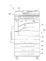
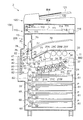
図2は、本実施の形態に係る画像形成装置2の外観図である。図3は、本実施の形態に係る画像形成装置2の内部構造を示す図である。
画像形成装置2は、原稿の画像を読み取る画像読取装置100と、画像データを基に用紙に画像を形成する画像形成手段の一例としての画像記録装置200と、を備えている。なお画像記録装置200は、画像形成装置1では、第1の画像形成手段として機能し、画像形成装置2では、第2の画像形成手段として機能する。また、画像形成装置2は、ユーザからの操作入力の受付やユーザに対する各種情報の表示を行うユーザインタフェース(UI)300と、画像形成装置2全体の動作を制御する制御装置900とを備える。
<Overall Description of Image Forming Apparatus>
Next, the entire
FIG. 2 is an external view of the
The
画像読取装置100は、画像読取手段の一例であり、画像形成装置2の上部に配置される。また画像記録装置200は、画像読取装置100の下側に配置され、制御装置900を内蔵している。ユーザインタフェース300は、画像形成装置2の上部の手前側、つまり画像読取装置100の後述する画像読取部110の手前側に配置されている。
The
まずは、画像読取装置100について説明する。
画像読取装置100は、原稿の画像を読み取る画像読取部110と、この画像読取部110に原稿を搬送する原稿搬送部120と、を備えている。原稿搬送部120は、画像読取装置100の上部に配置され、画像読取部110は、画像読取装置100の下部に配置されている。
原稿搬送部120は、原稿を収容する原稿収容部121と、この原稿収容部121から搬送された原稿が排出される原稿排出部122とを有し、原稿収容部121から原稿排出部122へ原稿を搬送する。
First, the
The
The
画像読取部110は、プラテンガラス111と、光を原稿の被読取面(画像面)へ照射する光照射ユニット112と、光照射ユニット112から原稿の被読取面へ光Lが照射されて原稿の被読取面で反射した光Lを導く導光ユニット113と、導光ユニット113によって導かれた光Lの光学像を結像する結像レンズ114と、を備えている。また、画像読取部110は、結像レンズ114によって結像された光Lを光電変換するCCD(Charge Coupled Device)イメージセンサ等の光電変換素子で構成され、結像された光学像を検出する検出部115と、検出部115と電気的に接続されて、検出部115によって得られた電気信号が送られる画像処理部116と、を備えている。
画像読取部110は、原稿搬送部120によって搬送される原稿の画像、及びプラテンガラス111に載せられた原稿の画像を読み取る。
The
The
次に、画像記録装置200について説明する。
画像記録装置200は、用紙上に画像を形成する画像形成部20と、画像形成部20に対して用紙Pを供給する用紙供給部60と、画像形成部20にて画像が形成された用紙Pを排出する用紙排出部70と、画像形成部20にて一方の面に画像が形成された用紙Pの表裏を反転させて再度画像形成部20に向けて搬送する反転搬送部80と、を備えている。
Next, the
The
画像形成部20は、一定の間隔を置いて並列的に配置されるイエロー(Y)、マゼンタ(M)、シアン(C)、黒(K)の4つの画像形成ユニット21(21Y、21M、21C、21K)を備えている。各画像形成ユニット21は、感光体ドラム22と、感光体ドラム22の表面を一様に帯電する帯電器23と、後述する光学系ユニット50によるレーザ照射によって形成された静電潜像を予め定められた色成分トナーで現像し可視化する現像器24とを備えている。また、画像形成部20には、画像形成ユニット21Y、21M、21C、21Kの現像器24に対して各色のトナーを供給するためのトナーカートリッジ29Y、29M、29C、29Kが設けられている。
The
画像形成部20は、画像形成ユニット21Y、21M、21C、21Kの下方に、画像形成ユニット21Y、21M、21C、21Kの感光体ドラム22に対してレーザ光を照射する光学系ユニット50を備えている。光学系ユニット50は、図示しない半導体レーザ、変調器の他、半導体レーザから出射されたレーザ光を偏向走査するポリゴンミラー(不図示)と、レーザ光を通過するガラス製のウィンドウ(不図示)と、各構成部材を密閉するためのフレーム(不図示)とを備えている。
The
また、画像形成部20は、画像形成ユニット21Y、21M、21C、21Kの感光体ドラム22に形成された各色のトナー像を中間転写ベルト31上に多重転写させる中間転写ユニット30と、中間転写ユニット30上に重畳されて形成されたトナー像を用紙Pに転写する二次転写ユニット40と、用紙P上に形成されたトナー像を加熱および加圧して定着する定着装置45と、を備えている。
The
中間転写ユニット30は、中間転写ベルト31と、この中間転写ベルト31を駆動するドライブローラ32と、中間転写ベルト31に一定のテンションを付与するテンションローラ33と、を備えている。また、中間転写ユニット30は、各感光体ドラム22と中間転写ベルト31を挟んで対向して感光体ドラム22上に形成されたトナー像を中間転写ベルト31上に転写するための複数(本実施の形態においては4つ)の一次転写ローラ34と、中間転写ベルト31を介して後述する二次転写ローラ41と対向するバックアップローラ35とを備えている。
The
中間転写ベルト31は、ドライブローラ32、テンションローラ33、複数の一次転写ローラ34、バックアップローラ35および従動ローラ36などの複数の回転部材に張りかけられている。そして、中間転写ベルト31は、駆動モータ(不図示)によって回転駆動されるドライブローラ32により、矢印方向に予め定められた速度で循環駆動される。この中間転写ベルト31は、例えば、ゴムまたは樹脂にて成形されたものが使用される。
また、中間転写ユニット30は、中間転写ベルト31上に存在する残留トナー等を除去するクリーニング装置37を備えている。クリーニング装置37は、トナー像の転写工程が終了した後の中間転写ベルト31の表面から残留トナーや紙粉等を除去する。
The
Further, the
二次転写ユニット40は、二次転写位置に設けられ中間転写ベルト31を介してバックアップローラ35を押圧し、用紙P上に画像を二次転写する二次転写ローラ41を備えている。二次転写ローラ41と、中間転写ベルト31を介して二次転写ローラ41と対向するバックアップローラ35とで、中間転写ベルト31に転写されたトナー画像が用紙Pに転写される二次転写位置が構成される。
定着装置45は、中間転写ユニット30によって二次転写された用紙P上の画像(トナー像)を、加熱定着ローラ46と加圧ローラ47とにより、熱および圧力を用いて用紙Pに定着させる。
The
The fixing
用紙供給部60は、画像が記録される用紙を収容する用紙収容部61と、用紙収容部61の各々に収容された用紙Pを送り出す送出ロール62と、送出ロール62にて送り出された用紙Pが搬送される搬送路63と、搬送路63に沿って配置され送出ロール62によって送り出された用紙Pを二次転写位置へ搬送する搬送ロール64、65、66と、を備えている。
The
用紙排出部70は、画像形成部20の上方に設けられて、画像形成部20にて画像が形成された用紙を積載する第1の積載トレイ71と、この第1の積載トレイ71と画像読取装置100との間に設けられて、画像形成部20にて画像が形成された用紙を積載する第2の積載トレイ72と、を備えている。
用紙排出部70は、定着装置45よりも搬送方向下流側に設けられて、トナー画像が定着された用紙Pを搬送する搬送ロール75と、この搬送ロール75の搬送方向下流側に設けられて、用紙Pの搬送方向を切り替える切替ゲート76と、を備えている。また、用紙排出部70は、切替ゲート76の搬送方向下流側に、切替ゲート76によって切り替えられた搬送方向の一方側(図3における右側)に搬送される用紙Pを第1の積載トレイ71に排出する第1の排出ロール77を備えている。また、用紙排出部70は、切替ゲート76の搬送方向下流側に、切替ゲート76によって切り替えられた搬送方向の他方側(図3における上側)に搬送される用紙Pを搬送する搬送ロール78と、搬送ロール78によって搬送される用紙Pを第2の積載トレイ72に排出する第2の排出ロール79と、を備えている。
The
The
反転搬送部80は、定着装置45の側方に、搬送ロール78を第2の積載トレイ72に用紙Pを排出する方向とは反対の方向に回転させることで反転された用紙Pが搬送される反転搬送路81を備えている。この反転搬送路81には、反転搬送路81に沿って複数の搬送ロール82が設けられている。これらの搬送ロール82によって搬送された用紙Pは、搬送ロール82によって、再度二次転写位置へ送り込まれる。
The
また、画像記録装置200は、画像形成部20、用紙供給部60、用紙排出部70、反転搬送部80および制御装置900を、直接的または間接的に支持する装置本体フレーム11と、この装置本体フレーム11に取り付けられて画像形成装置1の外面を形成する装置筐体12と、を備えている。
装置本体フレーム11は、画像形成装置1における横方向の一方の端部側で、内部に、切替ゲート76、第1の排出ロール77、搬送ロール78および第2の排出ロール79などを備えるとともに上下方向に伸びて、画像読取装置100を支持する読取装置支持部13を備えている。読取装置支持部13は、装置本体フレーム11における奥側の部位と協働して画像読取装置100を支持する。
The
The apparatus
また、画像記録装置200は、装置筐体12の一部として、画像形成部20の手前側に設けられるとともに、装置本体フレーム11に対して開閉可能に装着されるフロントカバー15を備えている。
ユーザは、フロントカバー15を開くことで、画像形成部20の中間転写ユニット30やトナーカートリッジ29Y、29M、29C、29Kを新しい物と取り替えることが可能となっている。
The
The user can replace the
ユーザインタフェース300は、例えばタッチパネルである。ユーザインタフェース300をタッチパネルにすることで、画像形成装置1の画像形成条件などの各種情報はタッチパネルに表示される。またユーザは、タッチパネルをタッチすることで画像形成条件などの入力操作を行う。
The
<制御装置の機能構成例>
図4は、制御装置900における信号処理系を示すブロック図である。なおここでは制御装置900が有する種々の機能のうち信号処理に関するものを選択して図示している。
制御装置900は、画像記録装置200にて画像を出力するために作成された画像データを取得するデータ取得部910と、画像データを受け取り、ページ記述言語(PDL:Page Description Language)に変換するPDL生成部920と、PDL生成部920により生成されたPDLからラスタイメージを作成するラスタライズ(rasterize)部930と、RGBデータをCMYKデータに変換する色変換処理部940と、CMYKデータの色調整を行う色調整部950と、色調整部950で色調整を行なうためのプロファイルを作成する色処理部960と、色調整部950により変換されたラスタイメージの調整を行なうラスタイメージ調整部970と、ハーフトーン処理を行なうハーフトーン処理部980と、色変換処理された画像データを画像記録装置200に出力する画像データ出力部990とを備える。
<Functional configuration example of control device>
FIG. 4 is a block diagram showing a signal processing system in the
The
本実施の形態では、まずデータ取得部910が画像データを受け取る。この画像データは、PCを使用するユーザが、画像形成装置2により印刷したい画像データである。
そして画像データは、PDL生成部920に送られ、PDL生成部920は、これをPDLで記述されたコードデータに変換して出力する。
In the present embodiment, first, the
Then, the image data is sent to the
ラスタライズ部930は、PDL生成部920から出力されてくるPDLで記述されたコードデータを各画素毎のラスタデータに変換し、ラスタイメージとする。そして、ラスタライズ部930は、変換後のラスタデータをRGB(Red、Green、Blue)のビデオデータ(RGBデータ)として出力する。このとき、ラスタライズ部930は、1ページ毎にRGBデータを出力することになる。
The
色変換処理部940は、ラスタライズ部930から入力されるRGBデータをデバイスインディペンデントなXYZのカラーバリューに変換した後、画像記録装置200の再現色(色材であるトナーの色:シアン(C)、マゼンタ(M)、イエロー(Y)、黒(K))であるCMYKデータに変換して出力する。このCMYKデータは、色毎に分離されたC色データ、M色データ、Y色データ、K色データからなる。
The color
色調整部950は、画像記録装置200で形成される画像の色調整を行う。色調整部950は、CMYKデータに対応して画像記録装置200で本来出力されるべき目標色に合うように、このCMYKデータの色調整を行う。なお画像形成装置2では、色調整部950は、画像形成装置1で出力される印刷物の色に合わせた画像とするための色調整を行うためにも使用される。この事項については後述する。
色調整は、例えば、CinMinYinKinデータをCoutMoutYoutKoutデータに変換する((Cin、Min、Yin、Kin)→(Cout、Mout、Yout、Kout))処理である。本実施の形態では、この変換は、CinMinYinKinデータをL*a*b*色空間等の他の色空間に変換せずに、CinMinYinKinデータと同じCMYK色空間中のCoutMoutYoutKoutデータに直接変換するいわゆるデバイスリンクプロファイルを用いることで行う。色調整部950は、このデバイスリンクプロファイルを記憶し、CinMinYinKinデータをこのデバイスリンクプロファイルに適用することで、色調整を行なう。
本実施の形態では、色調整部950は、画像形成装置2の画像記録装置200で形成される画像の色調整を行う色調整手段として機能する。またデバイスリンクプロファイルは、変換関係の一例であり、例えば、4次元LUT(Look up Table)として作成することができる。
The
For color adjustment, for example, C in M in Y in K in data is converted into C out M out Y out K out data ((C in , M in , Y in , K in ) → (C out , M out , Y out , K out )) processing. In this embodiment, this conversion is performed by converting C in M in Y in K in data into other color spaces such as L * a * b * color space and C in M in Y in K in data. It carried out by using a so-called device link profile that converts directly into C out M out Y out K out data in the same CMYK color space. The
In the present embodiment, the
色処理部960は、詳しくは後述するが、色調整部950で色調整を行うために使用されるデバイスリンクプロファイルを作成する。色処理部960は、色処理装置の一例である。また色処理部960は、色調整部950で色調整を行うために使用される変換関係(デバイスリンクプロファイル)を作成する変換関係作成手段の一例である。
As will be described in detail later, the
ラスタイメージ調整部970は、色調整部950から入力されるCoutMoutYoutKout、データに対し、γ変換、精細度処理、中間調処理等を施すことで、より良好な画質を画像記録装置200で得られるように各種の調整を行う。
The raster
ハーフトーン処理部980は、主走査方向および副走査方向に予め定められた閾値配列を有するディザマスクを使用したディザマスク処理により、画像データにハーフトーン処理を行う。これにより画像データは、例えば、多値で表されるものから二値で表されるものとなる。
The
画像データ出力部990は、色変換処理等の画像処理をされた画像データを画像記録装置200に出力する。
The image
<色処理部の説明>
次に画像形成装置2の色処理部960について詳述する。ここでは、色処理部960が、画像形成装置1で出力される印刷物の色に合わせた画像とする色調整を行う場合について説明を行う。
<Description of color processing unit>
Next, the
色処理部960は、上述したように色調整を行うために使用するデバイスリンクプロファイルを作成する。
図5は、色処理部960の機能構成について説明したブロック図である。
色処理部960は、画像データ取得部961と、色データ取得部962と、ばらつき取得部963と、位置ずれ取得部964と、領域群抽出部965と、第1の対応関係作成部966と、第2の対応関係取得部967と、第2の対応関係記憶部968と、変換関係作成部969とを備える。
The
FIG. 5 is a block diagram illustrating a functional configuration of the
The
画像データ取得部961は、色変換処理部940から画像データを取得する。即ち、この画像データは、CMYKデータであるとともにラスタデータである。
The image
色データ取得部962は、画像形成装置1の画像記録装置200により出力された画像G1(第1の画像)の色データ(第1の色データ)を取得する。この色データは、例えば、この印刷物を画像形成装置2の画像読取装置100を使用して読み取ることで取得する。即ち、画像読取装置100の画像読取部110が、印刷物の色度を読み取り、色データを生成する。色データとしては、デバイスに依存しないデータとして、例えばL*a*b*値が用いられる。L*a*b*値は、CIELAB色空間とも呼ばれるL*a*b*色空間で定義される値である。また、L*a*b*色空間は、明度L*と、色味を表す量の色度a*、b*とを軸とする直交座標色空間で表される。
The color
なお画像読取部110に備えられたCCDは通常RGBデータで画像を読み取る。ただし画像読取部110は、読み取った後でCCDの読取特性に応じた多次元テーブルによりRGBからL*a*b*に変換することで、L*a*b*値の色データを出力することができる。この多次元テーブルは、例えば、CCDの読取特性にしたがって作成されたICCプロファイルを使用することができる。
The CCD provided in the
ばらつき取得部963は、画像データの色のばらつきを算出することでこれを取得する。ばらつき取得部963が画像データの色のばらつきを取得する方法については後述する。
The
位置ずれ取得部964は、色のばらつきがより大きい領域において画像データと色データ(第1の色データ)との間の位置ずれ量を算出することでこれを取得する。つまり色データ(第1の色データ)は、上述のように画像読取部110で読み取られたものであるが、このとき位置ずれが生じることがある。
The
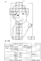
図6は、画像データと色データ(第1の色データ)との間で位置ずれが生じた例を示した図である。
この場合、色データ(第1の色データ)は、画像データに対して上下左右方向に移動(平行移動)したり、拡大縮小、回転が生じている。位置ずれ取得部964は、この位置ずれ量を取得する。なお位置ずれ量を取得する方法については後述する。
FIG. 6 is a diagram illustrating an example in which a positional deviation occurs between image data and color data (first color data).
In this case, the color data (first color data) has moved (translated) in the vertical and horizontal directions with respect to the image data, and has been enlarged / reduced and rotated. The positional
領域群抽出部965は、画像データを基に、色のばらつきがより小さい領域を領域群として抽出する。この領域群は、画像形成装置2で出力される印刷物の色を、画像形成装置1で出力される印刷物の色に合わせるために、双方の色の相違を把握するために設定される抽出領域から構成される。領域群抽出部965は、画像データ取得部961が取得したラスタデータから、領域群を抽出する。
The region
また領域群抽出部965は、抽出した領域群に関する情報を領域群情報として生成する。領域群情報は、領域群を構成する各抽出領域を特定できる情報を含む。例えば、色領域群情報は、各抽出領域の位置情報または画像情報を含むものであり、詳細については後述する。
The region
第1の対応関係作成部966は、位置ずれを合わせた上で、色のばらつきがより小さい領域において画像データと色データ取得部962で取得した色データ(第1の色データ)との対応関係である第1の対応関係を作成する。
この第1の対応関係は、画像データであるCMYKデータと、色データ(第1の色データ)であるL*a*b*データ(以後、この第1の色データを「L* 1a* 1b* 1データ」と言うことがある)との対応関係(CMYK−L* 1a* 1b* 1)となる。この第1の対応関係を作成する詳しい方法については、後述する。
The first
The first correspondence relationship, and CMYK data is image data, a color data (first color data) L * a * b * data (hereinafter, the
第2の対応関係取得部967は、画像データと画像形成装置2の第1の関係に対応する画像記録装置200についての第2の対応関係を取得する。
この第2の対応関係は、CMYKデータと、色データ(第2の色データ)であるL*a*b*データ(以後、この第2の色データを「L* 2a* 2b* 2データ」と言うことがある)との対応関係(CMYK−L* 2a* 2b* 2)となる。第2の対応関係は、第2の対応関係記憶部968に記憶されており、第2の対応関係取得部967は、第2の対応関係記憶部968から第2の対応関係を取得する。
The second correspondence
The second correspondence relationship is as follows: CMYK data and color data (second color data) L * a * b * data (hereinafter, the second color data is referred to as “L * 2 a * 2 b * 2”. sometimes referred to as data ") and the corresponding relationship to become (CMYK-L * 2 a * 2 b * 2). The second correspondence relationship is stored in the second correspondence
第2の対応関係は、予め作成され、第2の対応関係記憶部968に記憶される。第2の対応関係を作成するには、従来の方法を使用することができる。例えば、画像形成装置2の画像記録装置200の色域全体を網羅した色パッチの画像を印刷する。そしてこれを測色計等で測定して色データを取得する。このとき取得した色データは、第2の色データ(L* 2a* 2b* 2データ)となる。よって色パッチの画像を印刷するための画像データとこの第2の色データを対応付けることで、第2の対応関係が得られる。
The second correspondence relationship is created in advance and stored in the second correspondence
変換関係作成部969は、第1の対応関係および第2の対応関係から、画像G2(第2の画像)の色が画像G1(第1の画像)の色になるように、画像形成装置2の画像記録装置200の色調整を行う変換関係を作成する。
The conversion
具体的には、第1の対応関係と第2の対応関係の双方のL*a*b*データ(L* 1a* 1b* 1データとL* 2a* 2b* 2データ)を比較し、L*a*b*データが一致するときのCMYKデータ同士の対応関係を作成する。つまり第1の対応関係は、画像データであるCMYKデータと、このCMYKデータを入力したときに画像形成装置1で印刷される画像G1の色との関係を表す。また第2の対応関係は、同じCMYKデータを入力したときに画像形成装置2で印刷される画像G2の色との関係を表す。同じCMYKデータを入力しても、印刷される画像G1と画像G2とは、各々の装置特性が異なるため通常は同じ色とはならない。しかしながら変換関係は、画像形成装置1および画像形成装置2で印刷される画像の色が同じとなる場合のCMYKデータ同士の関係を表すものである。よって画像データであるCMYKデータを変換関係を使用して変換し、この変換後のCMYKデータを使用して画像形成装置2で印刷を行えば、画像形成装置1で印刷した画像G1と同じ色の画像G2が出力されることになる。つまりこの変換関係を使用することで、画像形成装置1から出力された印刷物の色に合わせ、画像形成装置2で印刷物を出力する色調整が行える。なおこの変換関係は、上述したように、4次元LUTであり、デバイスリンクプロファイルである。
Specifically, both the L * a * b * data of the first relationship and the second relationship (L * 1 a * 1 b * 1 data and L * 2 a * 2 b * 2 data) By comparison, a correspondence relationship between the CMYK data when the L * a * b * data matches is created. That is, the first correspondence relationship represents the relationship between CMYK data that is image data and the color of the image G1 printed by the
<ばらつき取得部の説明>
ばらつき取得部963は、画像データ取得部961が取得した画像データであるCMYKデータをいったんL*a*b*データに変換する。変換後の画像データは、L*a*b*データであるとともにラスタデータである。次にばらつき取得部963は、図7に示すように予め定められた大きさの走査矩形Tを設定し、この走査矩形Tでラスター画像を走査していく。
<Description of variation acquisition unit>
The
次にばらつき取得部963は、それぞれの走査矩形T内の画素について分散を求める。この分散は、走査矩形T内の各画素の画素値を(L0 *、a0 *、b0 *)、走査矩形T内の全画素の平均画素値を(Lave *、aave *、bave *)したときに、各画素について(L0 *−Lave *)2+(a0 *−aave *)2+(b0 *−bave *)2の値を考え、そしてこれを走査矩形T内の全画素について総和した値として定義できる。つまり分散は、下記数1式のようになる。
Next, the
![]()
![]()
ばらつき取得部963は、この分散をばらつきとして算出する。
The
<位置ずれ取得部の説明>
位置ずれ取得部964は、ばらつき取得部963が算出した分散を基に、色のばらつきがより大きい領域を抽出する。具体的には、位置ずれ取得部964は、分散が予め定められた閾値を超えた走査矩形Tを抽出する。
<Description of misalignment acquisition unit>
The
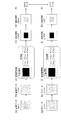
図8(a)〜(b)は、位置ずれ取得部964が色のばらつきがより大きい領域を抽出した結果について示した図である。
このうち図8(a)は、画像データを基に形成した画像G1(第1の画像)の例である。そしてこの画像G1中で示した矩形は、位置ずれ取得部964が抽出した走査矩形Tである。つまり分散が予め定められた閾値を超えた走査矩形Tを示している。また図8(b)は、抽出された走査矩形Tに対応する分散の値である。ここでは、上記閾値を300とし、分散が300を超えた場合に、色のばらつきがより大きい領域であるとしている。色のばらつきがより大きい領域としては、例えば、エッジ部が挙げられる。図8(a)の画像G1の場合、人物と背景との境界に位置する走査矩形Tが抽出されている。また人物の頭髪と肌との境界に位置する走査矩形Tが抽出されている。
FIGS. 8A and 8B are diagrams illustrating the result of the position
FIG. 8A shows an example of an image G1 (first image) formed based on the image data. And the rectangle shown in this image G1 is the scanning rectangle T which the position
なお設定された閾値を超える色のばらつきが大きい領域が見つからない場合もあり得る。この場合は、閾値をより小さい値に変更し、再度色のばらつきがより大きい領域を抽出する。また画像データと色データ(第1の色データ)のコントラストを強調する前処理を行い、その後で色のばらつきがより大きい領域を抽出するようにしてもよい。 There may be a case where an area having a large color variation exceeding the set threshold value cannot be found. In this case, the threshold value is changed to a smaller value, and an area having a larger color variation is extracted again. Alternatively, pre-processing for enhancing the contrast between the image data and the color data (first color data) may be performed, and then a region having a larger color variation may be extracted.
次に位置ずれ取得部964は、抽出された走査矩形Tにおいてテンプレートマッチングを行ない、画像データと色データ(第1の色データ)との間の位置ずれ量を取得する。
Next, the positional
図9(a)は、テンプレートマッチングについて説明した図である。
図9(a)は、画像データ中での走査矩形Tとこれに対応する位置の色データ(第1の色データ)中の矩形領域Uとを概念的に示した図である。
そして図9(a)において画像データ中の走査矩形Tの各画素の画素値を(L0 *、a0 *、b0 *)とする。またこれに対応する位置の色データ(第1の色データ)中の矩形領域Uの各画素の画素値を(L*、a*、b*)とする。
そして位置ずれ取得部964は、各画素について(L*−L0 *)+(a*−a0 *)+(b*−b0 *)の値を考え、そしてこれを走査矩形T内の全画素について総和した値として、下記数2式により定義される差分eを算出する。
FIG. 9A illustrates template matching.
FIG. 9A is a diagram conceptually showing a scanning rectangle T in image data and a rectangular area U in color data (first color data) at a position corresponding to the scanning rectangle T.
In FIG. 9A, the pixel value of each pixel of the scanning rectangle T in the image data is (L 0 * , a 0 * , b 0 * ). The pixel value of each pixel in the rectangular area U in the color data (first color data) at the position corresponding to this is defined as (L * , a * , b * ).
The
![]()
![]()
そして位置ずれ取得部964は、色データ(第1の色データ)中の矩形領域Uを画像中で左右上下方向にずらし、eが最小となるときの移動量を求める。eが最小となるときの移動量は、画像データと色データ(第1の色データ)とのこの箇所における位置ずれ量であると考えることができる。またこの位置ずれ量は、ここでは平行移動量として算出される。またここでは主走査方向の平行移動量をΔx、副走査方向の平行移動量をΔyとする。走査矩形T内の(x、y)に位置する画素が矩形領域U内の(u、v)に位置する画素に対応する場合、Δx=x−u、Δy=y−vと表すことができる。
Then, the positional
図9(b)は、位置ずれ取得部964で抽出した走査矩形Tにおいて、Δxを示した図である。また図9(c)は、位置ずれ取得部964で抽出した走査矩形Tにおいて、Δyを示した図である。
FIG. 9B is a diagram illustrating Δx in the scanning rectangle T extracted by the positional
次に位置ずれ取得部964は、図9(b)および図9(c)に示したΔx、Δyの中から誤差が大きい箇所を除外する。
図10(a)は、Δxの誤差が大きくなりやすい画像について示した図である。また図10(b)は、Δyの誤差が大きくなりやすい画像について示した図である。
図10(a)〜(b)の画像は、走査矩形Tや矩形領域Uの中にエッジ部を含む画像である。そして図10(a)の場合は、副走査方向の平行移動量Δyは、誤差が小さくなりやすいが、主走査方向の平行移動量Δxは、矩形領域Uをずらしても元の画像と変化が生じにくく、誤差が大きくなりやすい。また同様に図10(b)の場合は、主走査方向の平行移動量Δxは、誤差が小さくなりやすいが、副走査方向の平行移動量Δyは、矩形領域Uをずらしても元の画像と変化が生じにくく、誤差が大きくなりやすい。
Next, the positional
FIG. 10A is a diagram showing an image in which the error of Δx tends to increase. FIG. 10B is a diagram showing an image in which the error of Δy tends to increase.
The images in FIGS. 10A and 10B are images that include an edge portion in the scanning rectangle T or the rectangular region U. FIG. In the case of FIG. 10A, the error in the parallel movement amount Δy in the sub-scanning direction tends to be small, but the parallel movement amount Δx in the main scanning direction changes from the original image even if the rectangular area U is shifted. Less likely to occur and errors are likely to increase. Similarly, in the case of FIG. 10B, the error in the translation amount Δx in the main scanning direction tends to be small, but the translation amount Δy in the sub-scanning direction is the same as the original image even if the rectangular area U is shifted. Changes are less likely to occur and errors are likely to increase.
そこで位置ずれ取得部964は、例えば、以下の方法によりΔx、Δyの中から誤差が大きい箇所を除外する。
位置ずれ取得部964は、まずΔx、Δyのそれぞれについてヒストグラムを作成する。
図11は、Δx、Δyのそれぞれについて作成したヒストグラムを示した図である。図中横軸は、Δx、Δyの各値を表し、縦軸は、頻度を表す。
図示するようにΔxおよびΔyのヒストグラムは、それぞれについて点線で囲んだピークPx、およびピークPyを有する。そして大部分のΔxおよびΔyは、この点線内に入るが、この点線外のΔxおよびΔyについては、大きな誤差を含むものとして除外する。図示する例では、図中矢印で示したΔyの−19、−3、7について除外する。つまりΔxやΔyは、画像読取部110で画像G1を読み取ったときの主走査方向および副走査方向の位置ずれ量であり、画像全体で大きなばらつきは生じない。よってΔxやΔyについてヒストグラムを作成したときには、ピークPx、ピークPyが生ずることになる。そのためこのピークPx、ピークPyから外れたΔxおよびΔyについては、大きな誤差を含んでいると考えることができる。
Therefore, the positional
First, the positional
FIG. 11 is a diagram showing histograms created for each of Δx and Δy. In the figure, the horizontal axis represents each value of Δx and Δy, and the vertical axis represents the frequency.
As shown in the figure, the histogram of Δx and Δy has a peak Px and a peak Py surrounded by dotted lines, respectively. Most of Δx and Δy fall within this dotted line, but Δx and Δy outside this dotted line are excluded as including large errors. In the example illustrated, Δy −19, −3, and 7 indicated by arrows in the drawing are excluded. That is, Δx and Δy are the amount of positional deviation in the main scanning direction and the sub-scanning direction when the
さらに位置ずれ取得部964は、ピークPx内のΔx、およびピークPy内のΔyを使用してアフィン変換係数を求める。
アフィン変換係数は、下記数3式により定義されるa、b、c、d、e、fの各係数である。この場合、位置ずれ取得部964は、色のばらつきがより大きい領域における平行移動量のうち異常値を除いた平行移動量の総和を用いてアフィン変換係数を算出する、と言うことができる。
Further, the position
The affine transformation coefficients are coefficients a, b, c, d, e, and f defined by the following equation (3). In this case, it can be said that the positional

数3式により、画像データの(x、y)に位置する画素と色データ(第1の色データ)の(u、v)に位置する画素との対応関係がわかるようになる。この場合、色データ(第1の色データ)の(u、v)に位置する画素は、画像データの(x、y)の画素に対応し、位置ずれを補正すると互いに一致する画素である。また数3式により、上記走査矩形T内や矩形領域U内以外の領域についても対応関係がわかるようになる。
つまり位置ずれ取得部964は、色のばらつきがより大きい領域における画像データと色データ(第1の色データ)との間の位置ずれ量から、色のばらつきがより小さい領域における画像データと色データ(第1の色データ)との間の位置ずれ量を推定することができる。
Equation (3) makes it possible to know the correspondence between the pixel located at (x, y) in the image data and the pixel located at (u, v) in the color data (first color data). In this case, the pixels located at (u, v) of the color data (first color data) correspond to the (x, y) pixels of the image data, and are pixels that match each other when the positional deviation is corrected. In addition, the correspondence relationship can be understood for the regions other than the scanning rectangle T and the rectangular region U by the equation (3).
That is, the positional
またアフィン変換係数を使用すると、画像データと色データ(第1の色データ)との間の平行移動量、拡大縮小率および回転角を推定することができる。そしてこれは、上述した平行移動量であるΔx、Δyより求めることができる。よって位置ずれ取得部964は、色のばらつきがより大きい領域における画像データと色データ(第1の色データ)との間の平行移動量から、色のばらつきがより小さい領域における画像データと色データ(第1の色データ)との間の平行移動量、拡大縮小率および回転角を推定する、と言うこともできる。
When the affine transformation coefficient is used, it is possible to estimate the parallel movement amount, the enlargement / reduction ratio, and the rotation angle between the image data and the color data (first color data). This can be obtained from Δx and Δy which are the above-mentioned parallel movement amounts. Therefore, the position
なおこのとき色のばらつきがより小さい領域に対し色のばらつきがより大きい領域がより近くにあれば、推定された位置ずれ量の精度はより向上する。 At this time, if a region having a larger color variation is closer to a region having a smaller color variation, the accuracy of the estimated positional deviation amount is further improved.
<領域群情報の説明>
次に領域群抽出部965が生成する領域群情報について説明する。
領域群を構成する各抽出領域は、それぞれの抽出領域内の色がほぼ均一な領域(以下、均一領域と称する)であって、その均一領域間でほぼ同一の色信号である範囲が選択される。つまり画像データ内で色のばらつきが小さい領域が抽出される。均一領域間でほぼ同一の色信号を持てば、均一領域の大きさは同じである必要はない。
<Description of region group information>
Next, region group information generated by the region
Each extraction region constituting the region group is a region in which the colors in each extraction region are substantially uniform (hereinafter referred to as a uniform region), and a range having substantially the same color signal between the uniform regions is selected. The That is, a region with small color variation is extracted from the image data. If the color signals are almost the same between the uniform areas, the sizes of the uniform areas do not need to be the same.
図12(a)〜(b)は、領域群を生成する方法について示した図である。
領域群抽出部965は、上述した走査矩形T内に含まれる画素値のヒストグラムを作成する。
FIGS. 12A and 12B are diagrams showing a method for generating a region group.
The region
図12(a)は、1つの走査矩形Tについて作成されるヒストグラムの一例を示した図である。
図12(a)では、CMYK値で表されたラスター画像を、明度、彩度、色相で色を表すLCH色空間の色値に変換し、明度(L*)、彩度(C*)、色相(H*)のそれぞれのヒストグラムを作成した場合を示している。横軸は、明度(L*)、彩度(C*)、色相(H*)のそれぞれを表し、縦軸は、頻度を画素数で表している。
そしてこれらのヒストグラムから最も頻度の高いピークを含む範囲を主要色範囲として決定する。図12(a)では、この範囲を主要色範囲として図示している。そして走査矩形T内で主要色範囲内に入る領域を主要色領域とする。そして主要色領域の面積(画素数)が、走査矩形Tの面積(画素数)に対して予め定められた閾値以上であり、かつ主要色領域に含まれる画素の色分散が予め定められた閾値以内であったとき、この走査矩形Tを抽出領域として選定する。また隣接する走査矩形Tの主要色領域についても参照し、同じ色であれば、走査矩形Tを連結する。そしてさらにこの処理を連続して配置する走査矩形Tについて繰り返し、より大きい単位として1つにまとめる(グルーピング)。そしてグルーピングした後の主要色領域を、抽出領域とする。抽出領域は、例えば、図12(b)に示すように不定形の範囲となる。
なお図12(a)において予め定められた閾値を設け、ピークの高さがこの閾値に達しない場合は、このピークについては、主要色範囲とせず、抽出領域として選定しない方が望ましい。
FIG. 12A is a diagram showing an example of a histogram created for one scanning rectangle T. FIG.
In FIG. 12 (a), a raster image represented by CMYK values is converted into color values in the LCH color space representing colors by brightness, saturation, and hue, and the brightness (L * ), saturation (C * ), The case where each histogram of hue (H * ) is created is shown. The horizontal axis represents lightness (L * ), saturation (C * ), and hue (H * ), and the vertical axis represents frequency in number of pixels.
From these histograms, the range including the most frequent peak is determined as the main color range. In FIG. 12A, this range is illustrated as a main color range. An area that falls within the main color range within the scanning rectangle T is defined as a main color area. The area (number of pixels) of the main color region is equal to or larger than a predetermined threshold with respect to the area (number of pixels) of the scanning rectangle T, and the color dispersion of the pixels included in the main color region is a predetermined threshold. If it is within the range, this scanning rectangle T is selected as the extraction region. Further, the main color area of the adjacent scanning rectangle T is also referred to, and if the same color, the scanning rectangle T is connected. Further, this process is repeated for the scanning rectangles T that are continuously arranged and grouped into a larger unit (grouping). The main color area after grouping is set as an extraction area. The extraction area is, for example, an indefinite range as shown in FIG.
In FIG. 12A, a predetermined threshold value is provided, and when the peak height does not reach this threshold value, it is preferable that this peak is not selected as an extraction region without being a main color range.
領域群抽出部965は、領域群情報を作成する。領域群情報は、抽出領域の位置情報を含む。この位置情報は、例えば、外接矩形左上X座標、外接矩形左上Y座標、外接矩形幅、外接矩形高さ、Bitmap情報からなる。
外接矩形左上X座標および外接矩形左上Y座標は、図12(b)に示すような抽出領域に対し、点線で示す抽出領域の外接矩形を考え、この外接矩形の左上頂点のX座標およびY座標である。また外接矩形幅は、この外接矩形の幅Wであり、外接矩形高さは、この外接矩形の高さHである。これらの情報により外接矩形の位置が特定できる。
Bitmap情報は、外接矩形内で抽出領域に属する画素を「1」、それ以外の領域の画素を「0」とする2値からなる画像情報である。この場合、2値画像において、「1」の部分は、抽出領域であり、「0」の部分は、それ以外の領域であることを意味するため、外接矩形内での抽出領域の位置がわかることになる。
また領域群情報は、主要色領域の明度(L*)、彩度(C*)、色相(H*)のそれぞれの最小値(L* min、C* min、H* min)と最大値(L* max、C* max、H* max)の情報を含む。これにより抽出領域に含まれる色の色範囲がわかる。
The region
The circumscribing rectangle upper left X coordinate and circumscribing rectangle upper left Y coordinate consider the circumscribing rectangle of the extraction area indicated by the dotted line with respect to the extraction area as shown in FIG. It is. The circumscribed rectangle width is the width W of the circumscribed rectangle, and the circumscribed rectangle height is the height H of the circumscribed rectangle. With these pieces of information, the position of the circumscribed rectangle can be specified.
The Bitmap information is binary image information in which a pixel belonging to the extraction region within the circumscribed rectangle is “1” and a pixel in the other region is “0”. In this case, in the binary image, the portion “1” is the extraction region, and the portion “0” is the other region, so the position of the extraction region within the circumscribed rectangle is known. It will be.
The area group information includes minimum (L * min , C * min , H * min ) and maximum values (L * min , C * min , H * min ) of lightness (L * ), saturation (C * ), and hue (H * ) of the main color area. L * max , C * max , H * max ). As a result, the color range of the colors included in the extraction area is known.
<第1の対応関係を作成する方法の説明>
次に第1の対応関係作成部966が第1の対応関係を作成する方法について説明する。ここでは、Step1とStep2の2段階で第1の対応関係を作成する。
<Description of Method for Creating First Correspondence>
Next, a method in which the first
図13(a)〜(l)は、第1の対応関係作成部966が第1の対応関係を作成する際のStep1について説明した図である。
FIGS. 13A to 13L are diagrams for explaining
まず図13(a)は、画像データであるCMYKデータを示している。そしてこれを図13(b)に示すL*C*H*データに変換する。次に図13(c)に示す領域群情報を参照し、図13(d)に示すように、各抽出領域に含まれる画素についてのL*C*H*データを抽出する。これは、領域群情報に含まれる位置情報から各抽出領域の位置をまず特定し、さらに抽出領域のL*、C*、H*のそれぞれの最小値(L* min、C* min、H* min)と最大値(L* max、C* max、H* max)から、各抽出領域をさらに特定することで行う。
そして図13(e)に示すように再び、抽出領域内の各画素のL*、C*、H*データをCMYKデータに戻す。さらに抽出領域内の各画素のCMYKデータの平均をとり、これを図13(f)に示す各抽出領域のCMYKデータとする。
First, FIG. 13A shows CMYK data which is image data. This is converted into L * C * H * data shown in FIG. Next, referring to the area group information shown in FIG. 13C, as shown in FIG. 13D, L * C * H * data for the pixels included in each extraction area is extracted. This is because the position of each extraction area is first identified from the position information included in the area group information, and the minimum values (L * min , C * min , H *) of L * , C * , H * of the extraction area are further determined . min ) and a maximum value (L * max , C * max , H * max ), and further specifying each extraction region.
Then, as shown in FIG. 13E, the L * , C * , and H * data of each pixel in the extraction area are returned to the CMYK data. Further, the CMYK data of each pixel in the extraction area is averaged, and this is used as the CMYK data of each extraction area shown in FIG.
一方、図13(g)は、色データ(第1の色データ)であるL* 1a* 1b* 1データを示している。以後、図13(h)〜(j)は、上述した図13(b)〜(d)の処理と同様である。そして図13(k)に示すように再び、抽出領域内の各画素のL*、C*、H*データをL* 1a* 1b* 1データに戻す。さらに抽出領域内の各画素のL* 1a* 1b* 1データの平均をとり、これを図13(l)に示す各抽出領域のL* 1a* 1b* 1データとする。 On the other hand, FIG. 13 (g) shows a L * 1 a * 1 b * 1 data is color data (first color data). Thereafter, FIGS. 13H to 13J are the same as the processes of FIGS. 13B to 13D described above. And again, as shown in FIG. 13 (k), L * of each pixel of the extracted region, C *, returning H * data to L * 1 a * 1 b * 1 data. Further taking the average of the L * 1 a * 1 b * 1 data of each pixel in the extracted area, and L * 1 a * 1 b * 1 data for each extraction region shown in figure 13 (l).
そして図13(f)に示すように、各抽出領域のCMYKデータと図13(l)に示す領域群の各領域のL* 1a* 1b* 1データとを関連付ける。 Then, as shown in FIG. 13 (f), correlating the L * 1 a * 1 b * 1 data of each region of the CMYK data and area group shown in FIG. 13 (l) of each extraction region.
ただし画像データに含まれる色は、通常は画像形成装置1の色域全体を網羅するものとは言えない。そのためStep1の段階では、第1の対応関係(CMYK−L* 1a* 1b* 1)の数は、通常は少なく、精度のよい変換関係を作成するためには数が充足しているとは言えない場合が多い。そこで次のStep2において、不足分を補う処理を行う。
However, the colors included in the image data cannot usually be said to cover the entire color gamut of the
図14(a)〜(d)は、第1の対応関係作成部966が第1の対応関係を作成する際のStep2について説明した図である。
第1の対応関係作成部966は、画像データと取得した色データ(第1の色データ)とを、色データ(第1の色データ)の占める色域よりも広い色域に対して予め用意しておいた第1の対応関係候補に対して当てはめ整合させる。
図14(a)は、予め用意しておいた第1の対応関係候補について示した概念図である。
図14(a)で示した第1の対応関係候補は、画像形成装置1の色域全体(菱形で表した領域)について、第1の対応関係(CMYK−L* 1a* 1b* 1)の候補が予め用意されていることを示している。
FIGS. 14A to 14D are
The first
FIG. 14A is a conceptual diagram showing a first correspondence candidate prepared in advance.
Figure 14 (a) first correspondence candidate shown in, for the entire gamut of the image forming apparatus 1 (region expressed by diamonds), the first correspondence relationship (CMYK-L * 1 a * 1 b * 1 ) Candidates are prepared in advance.
また図14(b)は、Step1で得られた第1の対応関係(CMYK−L* 1a* 1b* 1)について示している。この場合、第1の対応関係は、6個のデータよりなる。
そして本実施の形態では、図14(c)に示すように、図14(a)に示した第1の対応関係候補に対して、図14(b)に示した画像データと取得した色データ(第1の色データ)とを当てはめ、合成する。
Also FIG. 14 (b) shows the first corresponding relationship obtained in Step1 (CMYK-L * 1 a * 1 b * 1). In this case, the first correspondence relationship consists of six pieces of data.
In this embodiment, as shown in FIG. 14C, the image data shown in FIG. 14B and the acquired color data are obtained for the first correspondence relationship candidate shown in FIG. (First color data) is applied and synthesized.
しかし図14(a)と図14(b)に含まれる各データは、必ずしも整合しているとは言えないため、単に当てはめるだけでなく、整合を行う処理を行う。例えば、図14(b)に含まれる各データから予め定められたユークリッド距離より近いものを図14(a)から除去する。または図14(b)に含まれる各データからのユークリッド距離に応じた重みを設定し、図14(b)に含まれる各データをこの重みにより重み付けをする。 However, since the data included in FIGS. 14A and 14B are not necessarily consistent, not only are they applied, but matching processing is performed. For example, data included in FIG. 14B that is closer than a predetermined Euclidean distance is removed from FIG. 14A. Or the weight according to the Euclidean distance from each data contained in FIG.14 (b) is set, and each data contained in FIG.14 (b) is weighted with this weight.
図14(d)は、ユークリッド距離dと設定される重みwについて示した図である。
図14(d)では、横軸がユークリッド距離dを表し、縦軸が重みwを表す。そしてw=1/(1+d)の関係としている。
この場合、設定される重みwは、図14(b)に含まれる各データからのユークリッド距離dがより近いほどより小さくなる。例えば、ユークリッド距離dが0の場合は、重みwは0であり、この場合、図14(a)に示したデータは、ないのと同じとなる。また設定される重みwは、図14(b)に含まれる各データからのユークリッド距離dがより遠いほどより大きくなる。そして予め定められたユークリッド距離d0より大きいときは、重みwは1となる。重みwが1の場合、重みwを設定しない場合と同様となる。
FIG. 14D is a diagram showing the Euclidean distance d and the set weight w.
In FIG. 14D, the horizontal axis represents the Euclidean distance d, and the vertical axis represents the weight w. The relationship is w = 1 / (1 + d).
In this case, the set weight w becomes smaller as the Euclidean distance d from each data included in FIG. For example, when the Euclidean distance d is 0, the weight w is 0. In this case, the data shown in FIG. Further, the set weight w becomes larger as the Euclidean distance d from each data included in FIG. When the Euclidean distance d 0 is greater than the predetermined distance, the weight w is 1. When the weight w is 1, it is the same as when the weight w is not set.
図14(c)では、図14(a)に含まれる各データのうち、除去もしくは重み付けの対象となるものの位置をD1〜D3で図示している。
このようにすることで、第1の対応関係作成部966は、Step1における第1の対応関係の数の不足分を補い、最終的な第1の対応関係(CMYK−L* 1a* 1b* 1)を作成する。
In FIG. 14C, the positions of the data to be removed or weighted among the data included in FIG. 14A are indicated by D1 to D3.
In this way, the first correspondence
なおStep1で得られた第1の対応関係(CMYK−L* 1a* 1b* 1)が、画像データに含まれる色が、画像形成装置1の色域全体を網羅するものである場合もあり得る。この場合は、上述したStep2の処理は必要ない。よってStep2の処理が必要であるか、必要でないかの第1の対応関係作成部966に判定部を設け、この判定部の判定結果によりStep2の処理を行うか否かを決定してもよい。この判定方法としては、例えば、画像形成装置1の色域を分割して、それぞれの分割領域で、図14(b)に示すデータがどの程度含まれるかの頻度分布を算出する。そして頻度が少ない分割領域があるか否かで判定を行う。
Note first correspondence relationship obtained in Step1 (CMYK-L * 1 a * 1 b * 1) is, colors included in the image data, even if it is intended to cover the entire gamut of the
また図14(a)で示した第1の対応関係候補は、図14(b)のStep1で得られた第1の対応関係に近いものであることが望ましい。両者が大きく異なると、上述した整合処理を行っても、両者の境界付近で色再現精度や連続性が低下する。
そこで第1の対応関係候補を予め複数用意し、その中から1つを選択するようにしてもよい。即ち、複数の第1の対応関係候補の中から、Step1で得られた第1の対応関係により近いものを選択する。この場合、例えば、第1の対応関係作成部966に第1の対応関係候補を選択して設定する設定部を設けてもよい。
Further, the first correspondence relationship candidate shown in FIG. 14A is desirably close to the first correspondence relationship obtained in
Therefore, a plurality of first correspondence relationship candidates may be prepared in advance, and one of them may be selected. That is, the one closer to the first correspondence obtained in
例えば、画像G1がJapanColor2011に近い条件で出力されていることがわかっていれば、複数の第1の対応関係候補の中に、JapanColor2011の条件のものを含ませるようにする。また他に、使用頻度が高い標準的な条件のものを含ませるようにしてもよい。あるいは過去に販売された画像形成装置について、代表的な条件のものを含ませるようにしてもよい。さらに複数の第1の対応関係候補を自動的に生成するようにしてもよい。 For example, if it is known that the image G1 is output under conditions similar to those of JapanColor2011, those having the conditions of JapanColor2011 are included in the plurality of first correspondence candidates. In addition, a standard condition that is frequently used may be included. Alternatively, image forming apparatuses sold in the past may be included in typical conditions. Further, a plurality of first correspondence relationship candidates may be automatically generated.
<画像形成装置2の色調整の手順の説明>
次に、画像形成装置2で画像形成装置1の色に合わせた画像G2を出力するための色調整を行う際の手順について説明する。
<Description of Color Adjustment Procedure of
Next, a procedure when the
図15は、画像形成装置2で画像形成装置1の色に合わせた画像G2を出力するための色調整を行う際の手順について説明したフローチャートである。
以下、図5および図15を用いて説明を行う。
FIG. 15 is a flowchart illustrating a procedure when the
Hereinafter, description will be made with reference to FIGS. 5 and 15.
まず画像形成装置1で出力した画像G1が印刷された印刷物およびこの印刷物を印刷したときの画像データを用意する(ステップ101)。
次に画像形成装置2の画像読取装置100で画像G1を読み取る(ステップ102)。
画像読取装置100で読み取られた画像G1の色データ(第1の色データ)は、制御装置900の色処理部960に送られ、制御装置900の色データ取得部962が、この色データ(第1の色データ)を取得する(ステップ103)。
First, a printed material on which the image G1 output by the
Next, the image G1 is read by the
The color data (first color data) of the image G1 read by the
一方、色処理部960では、色変換処理部940から画像データ取得部961が画像データを取得する(ステップ104)。
On the other hand, in the
次にばらつき取得部963が、画像データの色のばらつきを算出する(ステップ105)。ばらつき取得部963は、例えば、予め定められた大きさの走査矩形Tを設定し、走査矩形T内の画素について、数1式を使用して分散を求めることでばらつきを算出する。
Next, the
そして位置ずれ取得部964が、ばらつき取得部963が算出した分散を基に、色のばらつきがより大きい領域を抽出する(ステップ106)。この場合、位置ずれ取得部964は、分散が予め定められた閾値を超えた走査矩形Tを抽出する。
Then, based on the variance calculated by the
そして位置ずれ取得部964は、走査矩形Tと矩形領域Uとの間でテンプレートマッチングを行ない、画像データと色データ(第1の色データ)との間の位置ずれ量を求める(ステップ107)。具体的には、数2式を使用し、差分eが最小となるときの主走査方向の平行移動量Δxと副走査方向の平行移動量Δyを求める。
The positional
さらに位置ずれ取得部964は、平行移動量Δx、Δyのそれぞれについてヒストグラムを作成し、このヒストグラムにより、大きな誤差を含む平行移動量Δx、Δyを除外する(ステップ108)。
そして位置ずれ取得部964は、数3式を使用してアフィン変換係数を算出する(ステップ109)。これにより画像全体の位置ずれ量が把握できる。
Further, the positional
Then, the positional
そして領域群抽出部965が、色のばらつきがより小さい領域を領域群として抽出する(ステップ110)。領域群を抽出するには、例えば、図12で説明した方法を使用する。
Then, the area
次に第1の対応関係作成部966が、画像データと色データ取得部962で取得した色データ(第1の色データ)との対応関係である第1の対応関係を作成する(ステップ111)。第1の対応関係を作成するには、例えば、図13〜図14で説明した方法を使用する。このとき上述した位置ずれを合わせた上で第1の対応関係を作成する。
Next, the first
また第2の対応関係取得部967が、第2の対応関係記憶部968に記憶されている第2の対応関係を取得する(ステップ112)。
The second
そして変換関係作成部969が、第1の対応関係および第2の対応関係から、画像形成装置2の画像記録装置200の色調整を行う変換関係を作成する(ステップ113)。
この変換関係は、デバイスリンクプロファイルとして、色調整部950に出力する(ステップ114)。
色調整部950では、このデバイスリンクプロファイルにより、画像G2の色が画像G1の色になるように、画像データを変換する。これにより画像形成装置2で出力される画像G2は、画像形成装置1で出力される画像G1の色に合わせたものとなる。
Then, the conversion
This conversion relationship is output to the
The
以上詳述した方法によれば、画像データ中の色のばらつきが大きい領域においてまず位置ずれ量として平行移動量を取得する。そしてこの色のばらつきが大きい領域における平行移動量を基に、色のばらつきが小さい領域の位置ずれ量を推定する。推定された位置ずれ量は、平行移動量、拡大縮小率および回転角の情報を含む。これにより画像データと色データ(第1の色データ)との間の全体の位置ずれ量が把握できる。また第1の対応関係を作成するために使用する色のばらつきが小さい領域における位置ずれを高速かつ高精度に検出することができる。そのためデバイスリンクプロファイルの精度がより向上する。
また図7に示した走査矩形Tを1回走査させるだけで、位置ずれの検出に使用する色のばらつきが大きい領域と第1の対応関係を作成するために使用する色のばらつきが小さい領域とを決定することができる。そのため高速かつ高精度にデバイスリンクプロファイルを作成することができる。
According to the method described in detail above, first, the parallel movement amount is acquired as the positional deviation amount in the region where the color variation in the image data is large. Then, based on the parallel movement amount in the region where the color variation is large, the positional deviation amount in the region where the color variation is small is estimated. The estimated positional deviation amount includes information on the parallel movement amount, the enlargement / reduction ratio, and the rotation angle. Thereby, the total amount of positional deviation between the image data and the color data (first color data) can be grasped. In addition, it is possible to detect a positional shift in a region where the variation in color used for creating the first correspondence is small at high speed and with high accuracy. Therefore, the accuracy of the device link profile is further improved.
In addition, by scanning the scan rectangle T shown in FIG. 7 only once, a region having a large variation in color used for detecting a positional deviation and a region having a small variation in color used for creating the first correspondence relationship Can be determined. Therefore, a device link profile can be created at high speed and with high accuracy.
また以上詳述した方法によれば、画像形成装置1から出力した印刷物と画像データがあれば、画像形成装置1から出力された印刷物の色に合わせた印刷物が、画像形成装置2から出力される。この場合、画像形成装置1から出力した印刷物を画像形成装置2の画像読取装置100で読み取るが、画像形成装置に画像読取装置100が備えられている場合は、ユーザは、画像読取装置100において原稿を読み取らせるだけで、色調整が完了し、画像形成装置2で印刷が実行される。従ってユーザは、専門的なスキルを備えていなくてもよい。
また本実施の形態では、第1の対応関係作成部966が上述したStep2を行うことで、第1の対応関係を作成する。これにより画像形成装置1から出力した印刷物の画像G1に使用されている色が画像形成装置1の色再現範囲に対して部分的であっても、第1の対応関係作成部966は、より精度の高い変換関係を作成する。そのためこのような場合でも色調整の精度が低下しにくい。
According to the method described in detail above, if there is a printed matter and image data output from the
In the present embodiment, the first
なお以上詳述した例では、画像読取装置100は、画像形成装置2に内蔵されていたが、それぞれを別体とし、画像読取装置100を独立の装置としてもよい。
また同様に制御装置900は、画像形成装置2に内蔵されていたが、制御装置900の色処理部960で行う機能を独立させ、例えば、PC(Personal Computer)、タブレット端末、スマートフォン等により実行してもよい。この場合、色処理部960の機能は、これらの機器で動作するソフトウェア(プログラム)により実現することができる。
In the example described in detail above, the
Similarly, the
以上、本実施の形態について説明したが、本発明の技術的範囲は上記実施の形態に記載の範囲には限定されない。上記実施の形態に、種々の変更または改良を加えたものも、本発明の技術的範囲に含まれることは、特許請求の範囲の記載から明らかである。 Although the present embodiment has been described above, the technical scope of the present invention is not limited to the scope described in the above embodiment. It is clear from the description of the scope of the claims that various modifications or improvements added to the above embodiment are also included in the technical scope of the present invention.
1、2…画像形成装置、100…画像読取装置、200…画像記録装置、900…制御装置、950…色調整部、960…色処理部、961…画像データ取得部、962…色データ取得部、963…ばらつき取得部、964…位置ずれ取得部、965…領域群抽出部、966…第1の対応関係作成部、967…第2の対応関係取得部、968…第2の対応関係記憶部、969…変換関係作成部
DESCRIPTION OF
Claims (8)
前記画像データの色のばらつきを取得するばらつき取得部と、
色のばらつきがより大きい領域において前記画像データと前記色データとの間の位置ずれ量を取得する位置ずれ取得部と、
位置ずれを合わせた上で、色のばらつきがより小さい領域において前記画像データと前記色データとの対応関係である第1の対応関係を作成する第1の対応関係作成部と、
前記第1の対応関係、および当該第1の対応関係に対応する第2の画像形成手段についての第2の対応関係から、当該画像データを基に当該第2の画像形成手段により出力される第2の画像の色が前記第1の画像の色になるように、当該第2の画像形成手段の色調整を行う変換関係を作成する変換関係作成部と、
を備えることを特徴とする色処理装置。 A color data acquisition unit that acquires color data of the first image output by the first image forming unit based on the image data;
A variation obtaining unit for obtaining a variation in color of the image data;
A misregistration acquisition unit that acquires a misregistration amount between the image data and the color data in a region where color variation is larger;
A first correspondence creation unit that creates a first correspondence that is a correspondence between the image data and the color data in a region where color variation is smaller after adjusting the positional deviation;
From the first correspondence relationship and the second correspondence relationship for the second image forming means corresponding to the first correspondence relationship, the second image forming means output by the second image forming means based on the image data. A conversion relationship creating unit that creates a conversion relationship for performing color adjustment of the second image forming unit so that the color of the second image becomes the color of the first image;
A color processing apparatus comprising:
前記画像データの色のばらつきの程度を取得するばらつき取得部と、
色のばらつきがより大きい領域における前記画像データと前記色データとの間の位置ずれを取得するとともに、取得した位置ずれ量から色のばらつきがより小さい領域における当該画像データと当該色データとの間の位置ずれ量を推定する位置ずれ取得部と、
を備えることを特徴とする色処理装置。 A color data acquisition unit that acquires color data of the first image output by the first image forming unit based on the image data;
A variation acquisition unit for acquiring the degree of color variation of the image data;
Acquires a positional deviation between the image data and the color data in an area where the color variation is larger, and between the image data and the color data in an area where the color variation is smaller from the obtained positional deviation amount. A positional deviation acquisition unit for estimating the positional deviation amount of
A color processing apparatus comprising:
前記第2の画像形成手段で形成される画像の色調整を行う色調整手段と、
前記色調整手段で色調整を行うために使用される変換関係を作成する変換関係作成手段と、
を備え、
前記変換関係作成手段は、
前記画像データを基に第1の画像形成手段により出力された第1の画像の色データを取得する色データ取得部と、
前記画像データの色のばらつきを取得するばらつき取得部と、
色のばらつきがより大きい領域において前記画像データと前記色データとの間の位置ずれ量を取得する位置ずれ取得部と、
前記位置ずれ量を基に前記画像データと前記色データとの間の位置ずれを合わせる位置合わせ部と、
位置ずれを合わせた上で、色のばらつきがより小さい領域において前記画像データと前記色データとの対応関係である第1の対応関係を作成する第1の対応関係作成部と、
前記第1の対応関係、および当該第1の対応関係に対応する前記第2の画像形成手段についての第2の対応関係から、当該画像データを基に当該第2の画像形成手段により出力される第2の画像の色が前記第1の画像の色になるように、当該第2の画像形成手段の色調整を行う変換関係を作成する変換関係作成部と、
を備えることを特徴とする画像形成装置。 Second image forming means for forming an image on a recording material based on image data;
Color adjusting means for adjusting the color of an image formed by the second image forming means;
Conversion relation creating means for creating a conversion relation used for performing color adjustment in the color adjusting means;
With
The conversion relationship creating means includes:
A color data acquisition unit that acquires color data of the first image output by the first image forming unit based on the image data;
A variation obtaining unit for obtaining a variation in color of the image data;
A misregistration acquisition unit that acquires a misregistration amount between the image data and the color data in a region where color variation is larger;
An alignment unit that adjusts the positional deviation between the image data and the color data based on the positional deviation amount;
A first correspondence creation unit that creates a first correspondence that is a correspondence between the image data and the color data in a region where color variation is smaller after adjusting the positional deviation;
Based on the image data, the second image forming means outputs the first correspondence relation and the second correspondence relation for the second image forming means corresponding to the first correspondence relation. A conversion relationship creating unit that creates a conversion relationship for performing color adjustment of the second image forming means so that the color of the second image becomes the color of the first image;
An image forming apparatus comprising:
前記第2の画像形成手段で形成される画像の色調整を行う色調整手段と、
前記色調整手段で色調整を行うために使用される変換関係を作成する変換関係作成手段と、
を備え、
前記変換関係作成手段は、
前記画像データを基に前記第1の画像形成手段により出力された第1の画像の色データを取得する色データ取得部と、
前記画像データの色のばらつきを取得するばらつき取得部と、
色のばらつきがより大きい領域において前記画像データと前記色データとの間の位置ずれ量を取得する位置ずれ取得部と、
前記位置ずれ量を基に前記画像データと前記色データとの間の位置ずれを合わせる位置合わせ部と、
位置ずれを合わせた上で、色のばらつきがより小さい領域において前記画像データと前記色データとの対応関係である第1の対応関係を作成する第1の対応関係作成部と、
前記第1の対応関係、および当該第1の対応関係に対応する前記第2の画像形成手段についての第2の対応関係から、当該画像データを基に当該第2の画像形成手段により出力される第2の画像の色が前記第1の画像の色になるように、当該第2の画像形成手段の色調整を行う変換関係を作成する変換関係作成部と、
を備えることを特徴とする画像形成システム。 A first image forming means and a second image forming means for forming an image on a recording material based on image data;
Color adjusting means for adjusting the color of an image formed by the second image forming means;
Conversion relation creating means for creating a conversion relation used for performing color adjustment in the color adjusting means;
With
The conversion relationship creating means includes:
A color data acquisition unit that acquires color data of the first image output by the first image forming unit based on the image data;
A variation obtaining unit for obtaining a variation in color of the image data;
A misregistration acquisition unit that acquires a misregistration amount between the image data and the color data in a region where color variation is larger;
An alignment unit that adjusts the positional deviation between the image data and the color data based on the positional deviation amount;
A first correspondence creation unit that creates a first correspondence that is a correspondence between the image data and the color data in a region where color variation is smaller after adjusting the positional deviation;
Based on the image data, the second image forming means outputs the first correspondence relation and the second correspondence relation for the second image forming means corresponding to the first correspondence relation. A conversion relationship creating unit that creates a conversion relationship for performing color adjustment of the second image forming means so that the color of the second image becomes the color of the first image;
An image forming system comprising:
Priority Applications (2)
| Application Number | Priority Date | Filing Date | Title |
|---|---|---|---|
| JP2016002282A JP2017123588A (en) | 2016-01-08 | 2016-01-08 | Color processing apparatus, image formation device, and image formation system |
| US15/246,637 US10194058B2 (en) | 2016-01-08 | 2016-08-25 | Color processing device, image forming apparatus, and image forming system for matching the color of printed materials output in the past |
Applications Claiming Priority (1)
| Application Number | Priority Date | Filing Date | Title |
|---|---|---|---|
| JP2016002282A JP2017123588A (en) | 2016-01-08 | 2016-01-08 | Color processing apparatus, image formation device, and image formation system |
Publications (1)
| Publication Number | Publication Date |
|---|---|
| JP2017123588A true JP2017123588A (en) | 2017-07-13 |
Family
ID=59275038
Family Applications (1)
| Application Number | Title | Priority Date | Filing Date |
|---|---|---|---|
| JP2016002282A Pending JP2017123588A (en) | 2016-01-08 | 2016-01-08 | Color processing apparatus, image formation device, and image formation system |
Country Status (2)
| Country | Link |
|---|---|
| US (1) | US10194058B2 (en) |
| JP (1) | JP2017123588A (en) |
Families Citing this family (1)
| Publication number | Priority date | Publication date | Assignee | Title |
|---|---|---|---|---|
| JP6671265B2 (en) * | 2016-08-17 | 2020-03-25 | キヤノン株式会社 | Image processing apparatus, control method therefor, and program |
Citations (3)
| Publication number | Priority date | Publication date | Assignee | Title |
|---|---|---|---|---|
| JP2001202519A (en) * | 2000-01-24 | 2001-07-27 | Nippon Avionics Co Ltd | Method for aligning pattern |
| JP2008199658A (en) * | 2008-04-04 | 2008-08-28 | Olympus Corp | Image processor and image processing method thereof |
| WO2015072542A1 (en) * | 2013-11-15 | 2015-05-21 | 富士フイルム株式会社 | Color conversion table creation device and method, program, and recording medium |
Family Cites Families (11)
| Publication number | Priority date | Publication date | Assignee | Title |
|---|---|---|---|---|
| US6404517B1 (en) * | 1998-03-31 | 2002-06-11 | Seiko Epson Corporation | Color-patch sheet registration |
| US6512845B1 (en) * | 1999-07-20 | 2003-01-28 | Canon Kabushiki Kaisha | Iterative approximation of color patch area |
| US7038811B1 (en) * | 2000-03-31 | 2006-05-02 | Canon Kabushiki Kaisha | Standardized device characterization |
| JP3890211B2 (en) * | 2001-09-14 | 2007-03-07 | キヤノン株式会社 | Image processing method, image processing apparatus, program, and storage medium |
| EP1652668B1 (en) * | 2004-10-28 | 2017-03-29 | Hewlett-Packard Development Company, L.P. | Color accuracy check |
| US8203768B2 (en) * | 2005-06-30 | 2012-06-19 | Xerox Corporaiton | Method and system for processing scanned patches for use in imaging device calibration |
| US7800779B2 (en) * | 2005-12-21 | 2010-09-21 | Xerox Corporation | System and method for image based control using inline sensors |
| US7978366B2 (en) * | 2007-12-08 | 2011-07-12 | Konica Minolta Systems Laboratory, Inc. | Method for compensating for color variations among multiple printers |
| JP5733083B2 (en) | 2011-07-28 | 2015-06-10 | 株式会社リコー | Image processing apparatus and image processing system |
| JP5906924B2 (en) | 2012-04-27 | 2016-04-20 | 株式会社リコー | Image processing apparatus, image processing system, and program |
| KR102005766B1 (en) * | 2012-12-13 | 2019-10-01 | 휴렛-팩커드 디벨롭먼트 컴퍼니, 엘.피. | Print controlling apparatus, image forming apparatus, method for color revising and computer-readable recording medium |
-
2016
- 2016-01-08 JP JP2016002282A patent/JP2017123588A/en active Pending
- 2016-08-25 US US15/246,637 patent/US10194058B2/en active Active
Patent Citations (3)
| Publication number | Priority date | Publication date | Assignee | Title |
|---|---|---|---|---|
| JP2001202519A (en) * | 2000-01-24 | 2001-07-27 | Nippon Avionics Co Ltd | Method for aligning pattern |
| JP2008199658A (en) * | 2008-04-04 | 2008-08-28 | Olympus Corp | Image processor and image processing method thereof |
| WO2015072542A1 (en) * | 2013-11-15 | 2015-05-21 | 富士フイルム株式会社 | Color conversion table creation device and method, program, and recording medium |
Also Published As
| Publication number | Publication date |
|---|---|
| US20170201655A1 (en) | 2017-07-13 |
| US10194058B2 (en) | 2019-01-29 |
Similar Documents
| Publication | Publication Date | Title |
|---|---|---|
| US8767232B2 (en) | Image processing apparatus, image processing method, and computer-readable storage medium | |
| US7551334B2 (en) | Background suppression method and apparatus | |
| JP6357786B2 (en) | Image inspection apparatus, image inspection system, and image inspection method | |
| JP4496239B2 (en) | Image processing method, image processing apparatus, image forming apparatus, image reading apparatus, computer program, and recording medium | |
| US8451498B2 (en) | Image processing device, image processing method, tone-correction-parameter generation sheet, and storage medium | |
| JP6561669B2 (en) | Color processing apparatus, image forming apparatus, and image forming system | |
| US8619322B2 (en) | Image formation apparatus and image formation method for performing color deviation correction | |
| JP6834470B2 (en) | Color processing equipment, image forming equipment and image forming system | |
| JP4556242B2 (en) | Color tone correction method, color tone correction apparatus, image forming apparatus, and program | |
| US20090034869A1 (en) | Method and system for image background suppression using neutral adjustment of color channels | |
| CN102215314B (en) | Image processing apparatus and image forming method | |
| JP6834563B2 (en) | Color processing equipment, image forming equipment and image forming system | |
| JP2017123588A (en) | Color processing apparatus, image formation device, and image formation system | |
| US11451685B2 (en) | Color conversion table corrector that corrects the color conversion table according to data related to a first captured image excluding a specified area | |
| JP6981062B2 (en) | Color processing equipment, image forming equipment and image forming system | |
| JP2007178489A (en) | Image forming apparatus, image forming method, image adjusting method and program | |
| JP4505858B2 (en) | Image processing system, image processing method, and program | |
| JP6809163B2 (en) | Color processing equipment, image forming equipment and image forming system | |
| US20160086065A1 (en) | Image forming apparatus and image processing device | |
| JP2003324619A (en) | Image processing equipment and its control method | |
| JP7024495B2 (en) | Image processing equipment, image processing system and image processing program | |
| JP4271644B2 (en) | Image processing apparatus, image processing method, image processing program, and recording medium recording image processing program | |
| JP5092422B2 (en) | Image forming apparatus and image processing apparatus | |
| JP2021192489A (en) | Image forming apparatus, method for controlling image forming apparatus, and program | |
| JP2019062298A (en) | Information processing device, image formation system, and program |
Legal Events
| Date | Code | Title | Description |
|---|---|---|---|
| A621 | Written request for application examination |
Free format text: JAPANESE INTERMEDIATE CODE: A621 Effective date: 20181122 |
|
| A977 | Report on retrieval |
Free format text: JAPANESE INTERMEDIATE CODE: A971007 Effective date: 20190802 |
|
| A131 | Notification of reasons for refusal |
Free format text: JAPANESE INTERMEDIATE CODE: A131 Effective date: 20190813 |
|
| A521 | Request for written amendment filed |
Free format text: JAPANESE INTERMEDIATE CODE: A523 Effective date: 20191011 |
|
| A02 | Decision of refusal |
Free format text: JAPANESE INTERMEDIATE CODE: A02 Effective date: 20200121 |