EP1652668B1 - Color accuracy check - Google Patents
Color accuracy check Download PDFInfo
- Publication number
- EP1652668B1 EP1652668B1 EP04105367.9A EP04105367A EP1652668B1 EP 1652668 B1 EP1652668 B1 EP 1652668B1 EP 04105367 A EP04105367 A EP 04105367A EP 1652668 B1 EP1652668 B1 EP 1652668B1
- Authority
- EP
- European Patent Office
- Prior art keywords
- color
- selected areas
- proof
- areas
- area
- Prior art date
- Legal status (The legal status is an assumption and is not a legal conclusion. Google has not performed a legal analysis and makes no representation as to the accuracy of the status listed.)
- Expired - Fee Related
Links
Images

Classifications
-
- B—PERFORMING OPERATIONS; TRANSPORTING
- B44—DECORATIVE ARTS
- B44D—PAINTING OR ARTISTIC DRAWING, NOT OTHERWISE PROVIDED FOR; PRESERVING PAINTINGS; SURFACE TREATMENT TO OBTAIN SPECIAL ARTISTIC SURFACE EFFECTS OR FINISHES
- B44D3/00—Accessories or implements for use in connection with painting or artistic drawing, not otherwise provided for; Methods or devices for colour determination, selection, or synthesis, e.g. use of colour tables
- B44D3/003—Methods or devices for colour determination, selection or synthesis, e.g. use of colour tables
Definitions
- the invention relates to color accuracy checking in printed documents.
- an author will send a document to a remote location which is equipped and configured to perform a print job.
- the remote location includes printing presses that are well-suited to produce many copies of the document.
- producing a print job that includes a large number of copies involves some risk, in that if the copies include color errors the entire printed batch may be worthless. Such color errors can result, for example, when colors are not printed with enough accuracy, or when the printed colors do not represent the exact colors intended by the content designer.
- it is common to create a proof which is sent to the author, typically using a common carrier. If the proof is flawed, corrections may be made, and a second proof printed for the author's approval.
- This process can be continued and/or repeated until the results of the proof are correct (e.g. acceptable to the content designer).
- Upon approval of the proof a print job including many copies of the document can be printed. Accordingly, by using the proof, costly errors can be prevented. However, the entire process can be time-consuming, in part because the proof must be transmitted back to the author for approval.
- An alternate system involves insertion of color bars or some multi-color patches within a document contained within a print job.
- the color bars are configured to have a standardized appearance when properly printed.
- the printer at the remote location can print a proof of the document, including the required color bars.
- the color bars can be checked, to confirm that they are within tolerances of a standard appearance. The check may be made visually, by a person, or by use of a tool, such as a densitometer, colorimeter or spectrophotometer. Where the results of the check indicate, the print job may be completed.
- color bars are quite common, particularly in situations where color consistency between proofs printed at different sites, between proofs and a production run or between different production runs must be ensured. However, in many cases the color bars themselves are detrimental, in that it is generally not desirable to have color bars in the actual print job. Thus, after the proof is approved, the document file itself may be altered, to remove the color bars, or the printed pages may be cropped, thereby removing areas wherein the color bars are defined. Color bars also tend to provide a somewhat generic test of a subset of the colors contained within the proof, and do not provide any emphasis on a range of colors which are particularly important for the document.
- US 2002 104457 A1 relates to a method for controlling color on press during printing utilizing spectral measurements.
- a color-difference is exceeded the measured spectral reflectance values of a test area are compared with the corresponding target reflectance values from which a spectral reflectance difference is established.
- a linear equation is used to relate the spectral reflectance difference to solid ink density or ink layer thickness differences for ink regulation utilizing an on-line empirically established correction matrix such that the spectral reflectance difference is minimized.
- the control method is applicable to both process and non-process colors.
- a system and method for color accuracy checking is discussed.
- areas within a document are selected for color-checking.
- a confirmation is made that a second printing of the document has color values which deviate within tolerances from color values of a first printing of the document within each of the selected areas.
- examples of a system for color accuracy checking disclose checking of specific areas within proofs printed by proofers in first and second locations and confirming that the second proof deviates from the first by less than assigned tolerances.
- the system is configured with a first proofer for use by a document author.
- the document author can not only approve or reject the proof based on color or other factors, but can also select areas within the proof within which accuracy of the color is to be closely controlled.
- Each selected area can be assigned a color value or a color value range which is required for acceptance of the print job.
- Information indicating the selected locations and color ranges can be bundled with the job ticket and sent to a second proofer.
- the second proofer is located to allow convenient use by a job printer. The selected areas of a second proof are evaluated, and the print job is performed if the evaluation indicates that the selected areas of the second proof are within tolerances of the acceptable color values.
- Fig. 1 is an example of a color accuracy checking system 100 configured for production of a first proof at a first location, which may be conveniently located with respect to the document author. Areas within the first proof may be selected, and colors or color ranges associated with each of the selected areas.
- the color accuracy checking system 100 also provides for production of a second proof at a second location, which may be conveniently located with respect to a printing facility. The selected areas within the second proof are examined to determine if the colors within the selected areas are within the associated color ranges of the selected areas of the first proof.
- a first proofer 102 is configured to print a first proof 104 of a document 106.
- the document 106 can be in almost any format, such as PDF (portable document format) or others.
- a user interface 108 may be provided by the first proofer 102 or by a computer system (not shown) in communication with the first proofer 102.
- the user interface 108 may be configured to allow a user (e.g., the author of the document 106) to operate an area selector 110.
- the area selector 110 is configured to select, or facilitate selection of, one or more areas 112 within the proof 104 for association with colors or ranges of color within which a print job of the document must be restricted.
- the area selector 110 may be configured in software or hardware (e.g. as an application specific integrated circuit, i.e. an "ASIC").
- the selected areas 112 are typically areas within which it is particularly important that the color be closely controlled. For example, the user may operate the area selector 110 to select areas 112 of the proof 104 of the document 106 which contain corporate logos, peoples' faces or other objects for which control over the ultimate color in the print job is particularly important.
- the area selector 110 may include one or both of a manual area selector tool 114 and/or an automated area selector tool 116.
- the manual area selector tool 114 may utilize tools provided by the user interface 108 to allow the user to "circle" with a pointing device (e.g. a mouse) or otherwise manually define areas 112 within the document 106.
- a pointing device e.g. a mouse
- the user may utilize the manual area selector tool 114 to select areas within which are peoples' faces, corporate logos or other objects over which it is desired to maintain tight color control tolerances.
- the area selector 110 may include an automated area selector tool 116.
- the automated area selector tool 116 may be configured with algorithms which attempt to locate corporate logos, peoples' faces and other important areas within documents in an automated fashion. Upon location one or more such objects, an area may be defined about the object. Alternatively, the automated area selector tool 116 may select areas 112 in any fashion that appears appropriate. For example, one or more particularly colorful areas of the proof 104 of the document 106 may be selected automatically.
- An area examiner 118 is configured to operate one or more sensors 120 to examine the selected areas 112 within the proof 104. The area examiner 118 is therefore able to interpret signals coming from the sensor(s) 120 to determine a color value(s) for each area.
- the area examiner 118 may be configured in software or hardware (e.g. as an application specific integrated circuit, i.e. an "ASIC"). Additionally, the area examiner 118 may be configured to position the sensors 120 to examine the selected areas 112. In one embodiment, the area examiner 118 is configured to take measurements automatically, using information from the area selector 110, which indicates the areas which should be examined. Such an automatically operated area examiner 118 may be integrated into the printing system 100, such as within the first proofer 102.
- the measurements made by the area examiner 118 may be made during the printing process.
- the area examiner 118 could be configured within a second device; however, such a configuration may reduce overall efficiency.
- the sensors 120 may be any desired type of sensor, such as a colorimeter, a densitometer, a spectrophotometer or other sensor type.
- the user interface 108 may additionally be configured to allow the user to select a color range for each of the selected areas 112.
- the color range selected constitutes a range of colors within which the selected area of a second proof would be in compliance.
- the color range associated with each of the selected areas 112 provides a basis upon which the selected areas of the second proof may be evaluated. If one or more of the selected areas within the second proof are not within the range, then adjustments should be made, and the second proof re-printed. If the second (or subsequent) printing of the second proof is within the color range for each selected area 112, then printing of the second print job could be initiated.
- a job ticket maker 122 is configured to create a job ticket 124 for inclusion in a remote proof file 126.
- the remote proof file 126 includes the job ticket 124 and a copy of the document 106.
- the job ticket 124 (or another location, typically within the remote proof file 126) is configured to contain information on the locations of the selected areas 112 within the document 104, the colors and/or color ranges associated with each selected area 112, as well as the results of the color measurements of the selected areas 112 in the first proof 104.
- a second proofer 128 is configured to print a second proof 130.
- a user interface 132 may be configured to allow a user to examine the proof using an area examiner 134 or similar tool.
- the area examiner 134 would be configured to operate automatically, with little or no direction from the user interface, to examine the second proof 130 after it is printed.
- the area examiner 134 is configured to interpret the signals from one or more sensors 136, which are used to examine the selected areas 112 of the second proof 130 which are identified by the job ticket 124. The interpreted signals results in color data for each of the selected areas 112 for the second proof 130. The color data may be included within the job ticket 124.
- the area examiner 134 would examine the color values of the same portion of the person's face in the second proof 130.
- the area examiner 134 may be configured in software or hardware (e.g. as an application specific integrated circuit, i.e. an "ASIC").
- An area comparator 138 is configured to compare the measurement made by the sensors 136 and area examiner 134 of each of the selected areas on the second proof 130 with data containing the color measurements of each of the selected areas 112 of the first proof 104.
- the area comparator 138 may be configured in software or hardware (e.g. as an application specific integrated circuit, i.e. an "ASIC"). Where the measurements of the selected areas of the second proof 128 are within tolerances (e.g. within a range) indicated by data sent by the first proofer 102, the proof is approved. Where the measurements of the selected areas 112 of the second proof 128 are not within the tolerances, the second proof is rejected.
- the sensors 136 may be any desired type of sensor, such as a colorimeter, a densitometer, a spectrophotometer or other sensor type. However, the sensor 136 selected is typically of the same type and/or technology as the sensor 120.
- a message maker 142 is configured to create a message 144-which may be in the JMF (job messaging format)-for transmission back to the first proofer 102 and/or the operator of the user interface 108 or the author of the document 106.
- the message 144 may be configured to indicate the results of the examination by the area examiner 134 and sensor 136 and the results of the comparison by the area comparator 138 of the selected areas of the second proof 130.
- the message 144 created by the message maker 142 may indicate whether the second proof 130 created by the second proofer 128 was acceptably close to the first proof 104, and whether the print job 140 was indicated and/or actually produced.
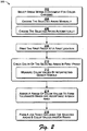
- Fig. 2 is an example of a method by which color accuracy checking may be performed, wherein a flow diagram 200 particularly shows events taking place on a first proofer 102 or proof originator.
- areas 112 within a first proof 104 of a document 106 are selected for color checking. This may be performed in a number of ways, two of which are listed here, and others of which may be easily envisioned in view of the optional embodiments listed herein. Where two or more ways of selecting areas for color checking are provided, the user may be allowed to elect between them. For example, the user may elect to select areas manually or the user may elect for the areas to be selected in an automated manner. In a first alternative, seen at block 204, the selected areas 112 are manually chosen.
- the selected areas 112 of the first proof 104 may be selected through use of a manual area selector tool 114, typically operated through a user interface 108.
- the user may indicate an area of the proof 104 for selection, such as the image of a corporate logo or a person's face.
- the selected areas may be chosen automatically.
- the selected areas 112 of the first proof 104 may be selected through use of an automated area selector tool 116.
- the first proof 104 is printed at a first location, such as the first proofer 102.
- the author of a document 106 uses a local proofer 102 to print the first proof 104.
- the first proof 104 is representative of any type of printing, made at the first location. While a common example of the first printing is the first proof 104, the first printing might alternatively be a first printing run of a document or a first part of a single run of a print job, printed at a first device.
- the color of the selected areas 112 of the first proof 104 are checked. This may be performed in a number of ways, one of which is listed here, and others of which may be easily envisioned in view of the optional embodiments listed herein.
- color values are measured by interpreting signals from the sensor 120 by the area examiner 118.
- the check of the selected areas 112 of the first proof 104 may be performed by sensors 120 which are integrated into the structure of the first proofer 102. Therefore, the check of the selected areas 112 may be made automatically, as the proof 104 moves within a paper path defined within the proofer 102.
- a range of color values may be assigned to form the tolerances which are acceptable in each of the selected areas 112.
- the user interface 108 may allow the user to assign a narrow range of colors which are acceptable for any given selected area 112, if the area's color is very important.
- the user interface 108 may allow the user to assign a somewhat broader range of colors which are acceptable for use within another selected area 112, if precise control over that area's color is less important.
- a job ticket 124 is formed to include descriptions of the locations of the selected areas 112 within the proof 104 of the document 106. Additionally, the job ticket 124 is configured to include color values or ranges which are associated with each of the selected areas 112.
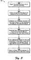
- Fig. 3 is an example of a method by which color accuracy checking may be performed, wherein a flow diagram 300 particularly shows events taking place on a second proofer 128 or proof receiver.
- a second proof at a second location is printed.
- second proof 130 may be printed by the second proofer 128 at the location of a printing press facility.
- the second proof 130 is representative of any type of printing, made at the second location. While a common example of the second printing is the second proof 130, the second printing might alternatively be a second printing run of a document or a second part of a single run of a print job, printed at a second device.
- color of the selected areas 112 of the second proof 130 are checked. This may be performed in a number of ways; for example, color values may be measured by interpreting signals from the sensor 136 by the area examiner 134.
- the checked colors of the first proof 104 are compared to the checked colors of the second proof 130 for each of the selected areas 112. In particular, at block 308 it is confirmed that-if true- the second proof has color values that are within tolerances of the first proof.
- a message is sent from the second location to the first location confirming that the second proof was within the color tolerances.
- a JMF message 144 is sent from the second proofer 128, located at a printing press site, to the first proofer 102, located at the site of the author of the document 106.
- a print job is printed according to the second proof and the job ticket.
- the job ticket 124 and document 106 are used to create the print job 140.
- Figs. 1-3 The hardware and software structures and functionality herein described, and seen in Figs. 1-3 , may be added retroactively to many proofers currently available on the commercial marketplace.
- the Hewlett-Packard Company manufactures and sells proofing devices adaptable for use in combination with the elements of Figs. 1-3 .
- the HP Design Jet 30 and HP Design Jet 130 printer series could be so adapted.
- the structures and functionality may be added to the design of an otherwise conventional proofer(s), thereby resulting in a proofer(s) having the enhanced qualities described in this document.
Description
- The invention relates to color accuracy checking in printed documents.
- It is frequently the case that an author will send a document to a remote location which is equipped and configured to perform a print job. Typically, the remote location includes printing presses that are well-suited to produce many copies of the document. Unfortunately, producing a print job that includes a large number of copies involves some risk, in that if the copies include color errors the entire printed batch may be worthless. Such color errors can result, for example, when colors are not printed with enough accuracy, or when the printed colors do not represent the exact colors intended by the content designer. As a result, it is common to create a proof, which is sent to the author, typically using a common carrier. If the proof is flawed, corrections may be made, and a second proof printed for the author's approval. This process can be continued and/or repeated until the results of the proof are correct (e.g. acceptable to the content designer). Upon approval of the proof, a print job including many copies of the document can be printed. Accordingly, by using the proof, costly errors can be prevented. However, the entire process can be time-consuming, in part because the proof must be transmitted back to the author for approval.
- An alternate system involves insertion of color bars or some multi-color patches within a document contained within a print job. The color bars are configured to have a standardized appearance when properly printed. Thus, the printer at the remote location can print a proof of the document, including the required color bars. The color bars can be checked, to confirm that they are within tolerances of a standard appearance. The check may be made visually, by a person, or by use of a tool, such as a densitometer, colorimeter or spectrophotometer. Where the results of the check indicate, the print job may be completed.
- Use of color bars is quite common, particularly in situations where color consistency between proofs printed at different sites, between proofs and a production run or between different production runs must be ensured. However, in many cases the color bars themselves are detrimental, in that it is generally not desirable to have color bars in the actual print job. Thus, after the proof is approved, the document file itself may be altered, to remove the color bars, or the printed pages may be cropped, thereby removing areas wherein the color bars are defined. Color bars also tend to provide a somewhat generic test of a subset of the colors contained within the proof, and do not provide any emphasis on a range of colors which are particularly important for the document. Thus, while the proof may appear to be correctly printed based on a review of colors present in the document which were tested by the color bars, colors in certain areas of the document may be somewhat altered from their desired hue. For example, a variety of different flesh tones may not be correctly printed. This error may result because the color bars may not be configured to provide adequate checking for the colors required by a particular print job.
- Accordingly, improved systems and methods for printing color documents from a remote location, while ensuring color consistency and accuracy, are required.
-
US 2002 104457 A1 relates to a method for controlling color on press during printing utilizing spectral measurements. When a color-difference is exceeded the measured spectral reflectance values of a test area are compared with the corresponding target reflectance values from which a spectral reflectance difference is established. A linear equation is used to relate the spectral reflectance difference to solid ink density or ink layer thickness differences for ink regulation utilizing an on-line empirically established correction matrix such that the spectral reflectance difference is minimized. The control method is applicable to both process and non-process colors. - A system and method for color accuracy checking is discussed. In one embodiment, areas within a document are selected for color-checking. A confirmation is made that a second printing of the document has color values which deviate within tolerances from color values of a first printing of the document within each of the selected areas.
- The following detailed description refers to the accompanying figures. In the figures, the left-most digit(s) of a reference number identifies the figure (Fig.) in which the reference number first appears. Moreover, the same reference numbers are used throughout the drawings to reference like features and components.
-
Fig. 1 is an example of a color accuracy checking system, illustrated as a block diagram. -
Fig. 2 is an example of a method by which color accuracy checking may be performed, wherein a flow diagram particularly shows events taking place on a proof originator. -
Fig. 3 is a second example of a method by which color accuracy checking may be performed, wherein a flow diagram particularly shows events taking place on a proof receiver. - As described herein, examples of a system for color accuracy checking disclose checking of specific areas within proofs printed by proofers in first and second locations and confirming that the second proof deviates from the first by less than assigned tolerances. In one example of the concepts illustrated, the system is configured with a first proofer for use by a document author. The document author can not only approve or reject the proof based on color or other factors, but can also select areas within the proof within which accuracy of the color is to be closely controlled. Each selected area can be assigned a color value or a color value range which is required for acceptance of the print job. Information indicating the selected locations and color ranges can be bundled with the job ticket and sent to a second proofer. In one example, the second proofer is located to allow convenient use by a job printer. The selected areas of a second proof are evaluated, and the print job is performed if the evaluation indicates that the selected areas of the second proof are within tolerances of the acceptable color values.
-
Fig. 1 is an example of a coloraccuracy checking system 100 configured for production of a first proof at a first location, which may be conveniently located with respect to the document author. Areas within the first proof may be selected, and colors or color ranges associated with each of the selected areas. The coloraccuracy checking system 100 also provides for production of a second proof at a second location, which may be conveniently located with respect to a printing facility. The selected areas within the second proof are examined to determine if the colors within the selected areas are within the associated color ranges of the selected areas of the first proof. - In the example of the color
accuracy checking system 100 ofFig. 1 , afirst proofer 102 is configured to print afirst proof 104 of adocument 106. Thedocument 106 can be in almost any format, such as PDF (portable document format) or others. A user interface 108 may be provided by thefirst proofer 102 or by a computer system (not shown) in communication with thefirst proofer 102. The user interface 108 may be configured to allow a user (e.g., the author of the document 106) to operate an area selector 110. - The area selector 110 is configured to select, or facilitate selection of, one or
more areas 112 within theproof 104 for association with colors or ranges of color within which a print job of the document must be restricted. The area selector 110 may be configured in software or hardware (e.g. as an application specific integrated circuit, i.e. an "ASIC"). The selectedareas 112 are typically areas within which it is particularly important that the color be closely controlled. For example, the user may operate the area selector 110 to selectareas 112 of theproof 104 of thedocument 106 which contain corporate logos, peoples' faces or other objects for which control over the ultimate color in the print job is particularly important. - The area selector 110 may include one or both of a manual
area selector tool 114 and/or an automatedarea selector tool 116. The manualarea selector tool 114 may utilize tools provided by the user interface 108 to allow the user to "circle" with a pointing device (e.g. a mouse) or otherwise manually defineareas 112 within thedocument 106. For example, the user may utilize the manualarea selector tool 114 to select areas within which are peoples' faces, corporate logos or other objects over which it is desired to maintain tight color control tolerances. - The area selector 110 may include an automated
area selector tool 116. The automatedarea selector tool 116 may be configured with algorithms which attempt to locate corporate logos, peoples' faces and other important areas within documents in an automated fashion. Upon location one or more such objects, an area may be defined about the object. Alternatively, the automatedarea selector tool 116 may selectareas 112 in any fashion that appears appropriate. For example, one or more particularly colorful areas of theproof 104 of thedocument 106 may be selected automatically. - An
area examiner 118 is configured to operate one ormore sensors 120 to examine the selectedareas 112 within theproof 104. Thearea examiner 118 is therefore able to interpret signals coming from the sensor(s) 120 to determine a color value(s) for each area. Thearea examiner 118 may be configured in software or hardware (e.g. as an application specific integrated circuit, i.e. an "ASIC"). Additionally, thearea examiner 118 may be configured to position thesensors 120 to examine the selectedareas 112. In one embodiment, thearea examiner 118 is configured to take measurements automatically, using information from the area selector 110, which indicates the areas which should be examined. Such an automatically operatedarea examiner 118 may be integrated into theprinting system 100, such as within thefirst proofer 102. Accordingly, the measurements made by thearea examiner 118 may be made during the printing process. Alternatively, thearea examiner 118 could be configured within a second device; however, such a configuration may reduce overall efficiency. Thesensors 120 may be any desired type of sensor, such as a colorimeter, a densitometer, a spectrophotometer or other sensor type. - The user interface 108 may additionally be configured to allow the user to select a color range for each of the selected
areas 112. The color range selected constitutes a range of colors within which the selected area of a second proof would be in compliance. The color range associated with each of the selectedareas 112 provides a basis upon which the selected areas of the second proof may be evaluated. If one or more of the selected areas within the second proof are not within the range, then adjustments should be made, and the second proof re-printed. If the second (or subsequent) printing of the second proof is within the color range for each selectedarea 112, then printing of the second print job could be initiated. - A
job ticket maker 122 is configured to create ajob ticket 124 for inclusion in aremote proof file 126. In one example, theremote proof file 126 includes thejob ticket 124 and a copy of thedocument 106. The job ticket 124 (or another location, typically within the remote proof file 126) is configured to contain information on the locations of the selectedareas 112 within thedocument 104, the colors and/or color ranges associated with each selectedarea 112, as well as the results of the color measurements of the selectedareas 112 in thefirst proof 104. - A
second proofer 128 is configured to print asecond proof 130. A user interface 132 may be configured to allow a user to examine the proof using anarea examiner 134 or similar tool. In one embodiment, thearea examiner 134 would be configured to operate automatically, with little or no direction from the user interface, to examine thesecond proof 130 after it is printed. To perform this examination, thearea examiner 134 is configured to interpret the signals from one ormore sensors 136, which are used to examine the selectedareas 112 of thesecond proof 130 which are identified by thejob ticket 124. The interpreted signals results in color data for each of the selectedareas 112 for thesecond proof 130. The color data may be included within thejob ticket 124. For example, if anarea 112 of thefirst proof 104 included a portion of a person's face, and was associated a specific color, then thearea examiner 134 would examine the color values of the same portion of the person's face in thesecond proof 130. Thearea examiner 134 may be configured in software or hardware (e.g. as an application specific integrated circuit, i.e. an "ASIC"). - An
area comparator 138 is configured to compare the measurement made by thesensors 136 andarea examiner 134 of each of the selected areas on thesecond proof 130 with data containing the color measurements of each of the selectedareas 112 of thefirst proof 104. Thearea comparator 138 may be configured in software or hardware (e.g. as an application specific integrated circuit, i.e. an "ASIC"). Where the measurements of the selected areas of thesecond proof 128 are within tolerances (e.g. within a range) indicated by data sent by thefirst proofer 102, the proof is approved. Where the measurements of the selectedareas 112 of thesecond proof 128 are not within the tolerances, the second proof is rejected. By rejecting thesecond proof 130, the prospect of having aprint job 140 wherein the color is incorrect in one or more selected areas is avoided. Note that thesensors 136 may be any desired type of sensor, such as a colorimeter, a densitometer, a spectrophotometer or other sensor type. However, thesensor 136 selected is typically of the same type and/or technology as thesensor 120. - A
message maker 142 is configured to create a message 144-which may be in the JMF (job messaging format)-for transmission back to thefirst proofer 102 and/or the operator of the user interface 108 or the author of thedocument 106. Themessage 144 may be configured to indicate the results of the examination by thearea examiner 134 andsensor 136 and the results of the comparison by thearea comparator 138 of the selected areas of thesecond proof 130. In particular, themessage 144 created by themessage maker 142 may indicate whether thesecond proof 130 created by thesecond proofer 128 was acceptably close to thefirst proof 104, and whether theprint job 140 was indicated and/or actually produced. -
Fig. 2 is an example of a method by which color accuracy checking may be performed, wherein a flow diagram 200 particularly shows events taking place on afirst proofer 102 or proof originator. At block 202,areas 112 within afirst proof 104 of adocument 106 are selected for color checking. This may be performed in a number of ways, two of which are listed here, and others of which may be easily envisioned in view of the optional embodiments listed herein. Where two or more ways of selecting areas for color checking are provided, the user may be allowed to elect between them. For example, the user may elect to select areas manually or the user may elect for the areas to be selected in an automated manner. In a first alternative, seen atblock 204, the selectedareas 112 are manually chosen. As seen earlier with respect to the discussion ofFig. 1 , the selectedareas 112 of thefirst proof 104 may be selected through use of a manualarea selector tool 114, typically operated through a user interface 108. In one example, the user may indicate an area of theproof 104 for selection, such as the image of a corporate logo or a person's face. In a second alternative, seen atblock 206, the selected areas may be chosen automatically. As seen earlier with respect to the discussion ofFig. 1 , the selectedareas 112 of thefirst proof 104 may be selected through use of an automatedarea selector tool 116. - At
block 208, thefirst proof 104 is printed at a first location, such as thefirst proofer 102. In one example, the author of adocument 106 uses alocal proofer 102 to print thefirst proof 104. In a more general example, thefirst proof 104 is representative of any type of printing, made at the first location. While a common example of the first printing is thefirst proof 104, the first printing might alternatively be a first printing run of a document or a first part of a single run of a print job, printed at a first device. - At
block 210, the color of the selectedareas 112 of thefirst proof 104 are checked. This may be performed in a number of ways, one of which is listed here, and others of which may be easily envisioned in view of the optional embodiments listed herein. In the example ofblock 212, color values are measured by interpreting signals from thesensor 120 by thearea examiner 118. The check of the selectedareas 112 of thefirst proof 104 may be performed bysensors 120 which are integrated into the structure of thefirst proofer 102. Therefore, the check of the selectedareas 112 may be made automatically, as the proof 104 moves within a paper path defined within theproofer 102. - At
block 214, a range of color values may be assigned to form the tolerances which are acceptable in each of the selectedareas 112. For example, the user interface 108 may allow the user to assign a narrow range of colors which are acceptable for any given selectedarea 112, if the area's color is very important. Similarly, the user interface 108 may allow the user to assign a somewhat broader range of colors which are acceptable for use within another selectedarea 112, if precise control over that area's color is less important. - At block 216 a
job ticket 124 is formed to include descriptions of the locations of the selectedareas 112 within theproof 104 of thedocument 106. Additionally, thejob ticket 124 is configured to include color values or ranges which are associated with each of the selectedareas 112. -
Fig. 3 is an example of a method by which color accuracy checking may be performed, wherein a flow diagram 300 particularly shows events taking place on asecond proofer 128 or proof receiver. Atblock 302, a second proof at a second location is printed. In one example,second proof 130 may be printed by thesecond proofer 128 at the location of a printing press facility. In a more general example, thesecond proof 130 is representative of any type of printing, made at the second location. While a common example of the second printing is thesecond proof 130, the second printing might alternatively be a second printing run of a document or a second part of a single run of a print job, printed at a second device. - At
block 304, color of the selectedareas 112 of thesecond proof 130 are checked. This may be performed in a number of ways; for example, color values may be measured by interpreting signals from thesensor 136 by thearea examiner 134. - At
block 306, the checked colors of thefirst proof 104 are compared to the checked colors of thesecond proof 130 for each of the selectedareas 112. In particular, atblock 308 it is confirmed that-if true- the second proof has color values that are within tolerances of the first proof. - At
block 310, a message is sent from the second location to the first location confirming that the second proof was within the color tolerances. In one embodiment, aJMF message 144 is sent from thesecond proofer 128, located at a printing press site, to thefirst proofer 102, located at the site of the author of thedocument 106. - At
block 312, a print job is printed according to the second proof and the job ticket. In the example illustrated, thejob ticket 124 and document 106 are used to create theprint job 140. - The hardware and software structures and functionality herein described, and seen in
Figs. 1-3 , may be added retroactively to many proofers currently available on the commercial marketplace. For example, The Hewlett-Packard Company manufactures and sells proofing devices adaptable for use in combination with the elements ofFigs. 1-3 . In particular, the HP Design Jet 30 andHP Design Jet 130 printer series could be so adapted. Alternatively, the structures and functionality may be added to the design of an otherwise conventional proofer(s), thereby resulting in a proofer(s) having the enhanced qualities described in this document.
Claims (15)
- A method for color accuracy checking, the method comprising:selecting areas within a document for color-checking;printing the document using a first proofer;checking color of the selected areas;assigning a range of color values which are acceptable in each of the selected areas andforming a job ticket including the selected areas and the range of color values for each of the selected areas;sending the job ticket to a second proofer;confirming that a second printing of the document has measured color values which deviate within tolerances from measured color values of a first printing of the document within each of the selected areas; wherein confirming further comprises:checking color of the selected area in the second printing;comparing the checked color of the selected area within the first document to the checked color of the selected area within the second document; andsending a message from the second proofer to the first proofer confirming the second printing was within the range of color values.
- The method of claim 1, wherein the first and second printings are:first and second proofs;first and second runs of the same document; orfirst and second parts of a single run printed on first and second devices.
- The method of claim 1 or claim 2, wherein selecting areas comprises:manually choosing the selected areas.
- The method of claim 1 or claim 2, wherein selecting areas comprises:automatically choosing the selected areas.
- The method of any one of claims 1 through 5, wherein the confirming comprises:measuring color values by interpreting signals from a sensor to obtain color values for each of the selected areas.
- The method of claim 1, wherein forming the job ticket comprises:expressing the color values for each of the selected areas as a range, wherein breadth of each range is controlled according to a required precision of the associated selected area.
- The method of any one of claims 1 through 6, additionally comprising:printing the first and second printings at different locations.
- The method of any one of claims 1 through 10, additionally comprising:printing a print job according to the second printing, when the color values of the second printing are within the tolerances of the color values of the first printing for each of the selected areas.
- One or more computer-readable media comprising computer-executable instructions configured to implement the method steps of any one of claims 1 through 8.
- A color accuracy checking apparatus (100), comprising:an area selector (110), configured to select areas within a proof (104) for color accuracy checking;an area examiner (118), configured to examine each of the selected areas (112) within the proof (104) to determine color values for each of the selected areas (112); anda job ticket maker (122) to form a job ticket (124) comprising locations of each of the selected areas (112) and associated color values for each of the selected areas (112);a first proofer (102) to print the proof (104); anda sensor (120) configured within the first proofer (102) to examine the proof (104) in response to the area examiner (118).a second proofer (128) to receive a file (126) comprising the job ticket (124) and document (106) and to create a second proof (130);a second sensor (136) configured within the second proofer (128) to examine the second proof (130) at the selected areas (112) as indicated by the job ticket (124) to obtain second measurements of the selected areas (112); anda message maker (142) to report if the second measurements deviated from the color values in the job ticket (124)..
- The color accuracy checking apparatus (100) of claim 10, wherein the area selector (110) comprises:a user interface (108); anda tool (114), operable through the user interface (108), to allow the selected areas (112) to be indicated by manual operation.
- The color accuracy checking apparatus (100) of claim 11, wherein the user interface (108) allows each of the selected areas (112) to be associated with an amount by which color within the selected area (112) may be allowed to vary.
- The color accuracy checking apparatus (100) of any one of claims 10 through 12, wherein the area examiner (118) comprises a sensor (136) selected from a group of sensors consisting of a colorimeter, a densitometer and a spectrophotometer.
- The color accuracy checking apparatus (100) of any one of claims 10 through 13, wherein:the job ticket maker (122) is configured to include within the job ticket (124) an amount by which color within each of the selected areas (112) may vary; and the job ticket (124) is configured in Job Definition Format.
- The color accuracy checking apparatus (100) of claim 10, wherein the message maker (142) reports using Job Messaging Format.
Priority Applications (3)
| Application Number | Priority Date | Filing Date | Title |
|---|---|---|---|
| EP04105367.9A EP1652668B1 (en) | 2004-10-28 | 2004-10-28 | Color accuracy check |
| US11/234,923 US8928935B2 (en) | 2004-10-28 | 2005-09-26 | Color accuracy check |
| JP2005313956A JP4188358B2 (en) | 2004-10-28 | 2005-10-28 | Method and apparatus for checking color accuracy |
Applications Claiming Priority (1)
| Application Number | Priority Date | Filing Date | Title |
|---|---|---|---|
| EP04105367.9A EP1652668B1 (en) | 2004-10-28 | 2004-10-28 | Color accuracy check |
Publications (2)
| Publication Number | Publication Date |
|---|---|
| EP1652668A1 EP1652668A1 (en) | 2006-05-03 |
| EP1652668B1 true EP1652668B1 (en) | 2017-03-29 |
Family
ID=34929779
Family Applications (1)
| Application Number | Title | Priority Date | Filing Date |
|---|---|---|---|
| EP04105367.9A Expired - Fee Related EP1652668B1 (en) | 2004-10-28 | 2004-10-28 | Color accuracy check |
Country Status (3)
| Country | Link |
|---|---|
| US (1) | US8928935B2 (en) |
| EP (1) | EP1652668B1 (en) |
| JP (1) | JP4188358B2 (en) |
Families Citing this family (14)
| Publication number | Priority date | Publication date | Assignee | Title |
|---|---|---|---|---|
| US7701625B2 (en) * | 2006-09-21 | 2010-04-20 | Xerox Corporation | Critical color tolerance guide for printers |
| US8189233B2 (en) * | 2007-10-23 | 2012-05-29 | Fujifilm Corporation | Density calculating apparatus, density setting apparatus, density calculating program storage medium, and density setting program storage medium |
| JP2010151606A (en) * | 2008-12-25 | 2010-07-08 | Ricoh Co Ltd | Image inspecting apparatus, image inspection method and program |
| US8649044B2 (en) * | 2010-01-29 | 2014-02-11 | Hewlett-Packard Development Company, L.P. | Computer processing of differences between print job files |
| US9100620B2 (en) * | 2010-05-25 | 2015-08-04 | Xerox Corporation | Method and system for adding a color bar as a rendering job ticket attribute |
| JP2012056179A (en) * | 2010-09-08 | 2012-03-22 | Canon Inc | Image processing apparatus, method for controlling the image processing apparatus and program |
| US9747681B2 (en) | 2013-03-27 | 2017-08-29 | Prosper Creative Co., Ltd. | Measuring apparatus, measurement method, information processing apparatus, and measurement program |
| US20140307286A1 (en) * | 2013-04-15 | 2014-10-16 | Xerox Corporation | Driver-based print preview, reduced size proofing, and virtual printing of documents |
| WO2016047378A1 (en) | 2014-09-26 | 2016-03-31 | 富士フイルム株式会社 | Measurement position presentation method, measurement position presentation guide production method, printed matter measurement method, printed matter measurement position determination method, and printed matter measurement position determination device |
| JP2017123588A (en) * | 2016-01-08 | 2017-07-13 | 富士ゼロックス株式会社 | Color processing apparatus, image formation device, and image formation system |
| JP2019114883A (en) * | 2017-12-22 | 2019-07-11 | コニカミノルタ株式会社 | Color verification device, color verification system, and program |
| USD1003317S1 (en) | 2021-03-09 | 2023-10-31 | Esko Software Bv | Display screen or portion thereof with graphical user interface |
| US11775238B2 (en) | 2021-10-29 | 2023-10-03 | Ricoh Company, Ltd. | Image forming apparatus, image forming system, and image forming method for color difference calculation |
| JP2024018317A (en) * | 2022-07-29 | 2024-02-08 | ブラザー工業株式会社 | Printing device, color measurement method and color measurement program |
Family Cites Families (32)
| Publication number | Priority date | Publication date | Assignee | Title |
|---|---|---|---|---|
| GB8418588D0 (en) | 1984-07-20 | 1984-09-12 | Harmon Frances Ltd | Removing metals from aqueous solutions |
| FR2660090B1 (en) | 1990-03-23 | 1994-07-29 | Thomson Csf | DEVICE FOR VIEWING BY PROJECTION WITH A FEEDBACK LOOP FOR CORRECTING ALL OF THE DEFECTS IN THE PROJECTED IMAGE. |
| US5363318A (en) * | 1992-03-23 | 1994-11-08 | Eastman Kodak Company | Method and apparatus for adaptive color characterization and calibration |
| US5600574A (en) * | 1994-05-13 | 1997-02-04 | Minnesota Mining And Manufacturing Company | Automated image quality control |
| US5809366A (en) * | 1995-03-24 | 1998-09-15 | Ricoh Company, Ltd. | Method and system for calibrating a color copier |
| DE19515499C2 (en) * | 1995-04-27 | 1997-03-06 | Heidelberger Druckmasch Ag | Process for simultaneous multi-color control during printing |
| JP3661230B2 (en) | 1995-06-30 | 2005-06-15 | 凸版印刷株式会社 | Print quality control device |
| US6043909A (en) | 1996-02-26 | 2000-03-28 | Imagicolor Corporation | System for distributing and controlling color reproduction at multiple sites |
| JPH10764A (en) * | 1996-06-18 | 1998-01-06 | Canon Aptecs Kk | Printing control apparatus, method therefor, and printing apparatus |
| AU9119098A (en) | 1997-08-25 | 1999-03-16 | Richard A. Holub | A system for distributing and controlling color reproduction at multiple sites |
| JP2000013627A (en) | 1998-06-24 | 2000-01-14 | Fuji Photo Film Co Ltd | Color converting method |
| US6215562B1 (en) | 1998-12-16 | 2001-04-10 | Electronics For Imaging, Inc. | Visual calibration |
| US6469805B1 (en) | 1998-12-18 | 2002-10-22 | Xerox Corporation | Post raster-image processing controls for digital color image printing |
| US6185001B1 (en) | 1999-02-01 | 2001-02-06 | The Standard Register Company | Printed document and method of determining the print quality of a printed document |
| JP3384769B2 (en) * | 1999-04-19 | 2003-03-10 | リョービ株式会社 | Ink supply amount adjustment device and ink supply amount adjustment method |
| US6624908B1 (en) | 1999-10-01 | 2003-09-23 | Global Graphics Software Limited | Method for arranging a prepress workflow |
| US6380951B1 (en) | 1999-10-01 | 2002-04-30 | Global Graphics Software Limited | Prepress workflow method and program |
| US6483524B1 (en) | 1999-10-01 | 2002-11-19 | Global Graphics Software Limited | Prepress workflow method using raster image processor |
| US6381343B1 (en) | 2000-04-07 | 2002-04-30 | Lotsadots, Inc. | Remote print press proofing system |
| JP2002086689A (en) * | 2000-09-13 | 2002-03-26 | Komori Corp | Method and device for color administration for printing machine |
| US7110143B2 (en) * | 2000-12-06 | 2006-09-19 | Xerox Corporation | Accurate printing of proprietary mark patterns and colors |
| US6564714B2 (en) * | 2000-12-06 | 2003-05-20 | Delaware Capital Formation, Inc. | Spectral color control method |
| US20020126328A1 (en) * | 2001-03-09 | 2002-09-12 | Lehmeier Michelle R. | Method and apparatus for matching color image data with a corresponding color in a defined color space |
| US6607258B2 (en) | 2001-04-11 | 2003-08-19 | Hewlett-Packard Development Company, L.P. | Proofing data file generated by target printer facility |
| US7327481B2 (en) * | 2001-05-30 | 2008-02-05 | Hewlett-Packard Development Company, L.P. | Open coventuring in a remote hardcopy proofing service, with preserved clientele, through interface sharing |
| JP2003060928A (en) * | 2001-08-20 | 2003-02-28 | Fuji Photo Film Co Ltd | Image output system management method |
| US6721068B2 (en) | 2002-02-19 | 2004-04-13 | Mark A. Weiss | Two-part color bar process to ensure validity of proof |
| EP1404102A1 (en) * | 2002-09-26 | 2004-03-31 | Hewlett-Packard Company, A Delaware Corporation | System and method for printing from a digital camera image proof sheet |
| US7453597B2 (en) * | 2003-01-17 | 2008-11-18 | Hewlett-Packard Development Company, L.P. | Proof-document formatting to enable full-capability remote proofing in a completely standard proofing station |
| US7589851B2 (en) * | 2003-04-02 | 2009-09-15 | Agfa Graphics Nv | System for job control of a document processing system and method for job control of document processing process |
| US7233398B2 (en) * | 2003-05-29 | 2007-06-19 | Konica Minolta Medical & Graphic, Inc. | Colorimeter measured value control system and colorimeter measured value control method thereof, and a color control information providing system and a color control information providing method thereof |
| JP2005063168A (en) * | 2003-08-13 | 2005-03-10 | Konica Minolta Medical & Graphic Inc | Color adjustment method, program for making computer execute the color adjustment method, and computer-readable information storage medium storing the program |
-
2004
- 2004-10-28 EP EP04105367.9A patent/EP1652668B1/en not_active Expired - Fee Related
-
2005
- 2005-09-26 US US11/234,923 patent/US8928935B2/en not_active Expired - Fee Related
- 2005-10-28 JP JP2005313956A patent/JP4188358B2/en not_active Expired - Fee Related
Non-Patent Citations (1)
| Title |
|---|
| None * |
Also Published As
| Publication number | Publication date |
|---|---|
| US20060092442A1 (en) | 2006-05-04 |
| US8928935B2 (en) | 2015-01-06 |
| JP4188358B2 (en) | 2008-11-26 |
| EP1652668A1 (en) | 2006-05-03 |
| JP2006153864A (en) | 2006-06-15 |
Similar Documents
| Publication | Publication Date | Title |
|---|---|---|
| US8928935B2 (en) | Color accuracy check | |
| US8654395B2 (en) | Method and test element for determining characterization data of a printing process and apparatus for carrying out the method | |
| EP1437222B2 (en) | Printing method, printed matter, and printing controller | |
| US7262880B2 (en) | Apparatus and method for creating color-calibration characteristic curves and/or process-calibration characteristic curves | |
| JP2007266841A (en) | Image output control apparatus | |
| US8451503B2 (en) | Print quality control method | |
| US6389968B1 (en) | Ink supply control device for printing machines and a method therefor | |
| US7298526B2 (en) | Method for confirming correct selection of an output profile of a printer | |
| CN111267467B (en) | Offset printing standard test plate and production and application method thereof | |
| EP1813922A1 (en) | Display apparatus, display method, and control program | |
| JP4780316B2 (en) | Image output control device | |
| US7688486B2 (en) | Methods and apparatus for profiling color output devices | |
| EP1512117B1 (en) | Proofing paper with pre-printed color bar and method of creating hard proof using the same | |
| AU2001258580A1 (en) | Calibrating printing machines | |
| US20050264640A1 (en) | Color control system and color control method | |
| US20160004941A1 (en) | Method for calculating substitution colors for spot colors | |
| WO2005067278A1 (en) | Methods and apparatus for colorimetrically characterizing color deviation in color imaging devices | |
| US7365876B2 (en) | Method for generating a color match between a target object and a source object | |
| JP2002301807A (en) | Picture color tone control method and device for printing machine | |
| US8842323B2 (en) | Print engine for printing a print job using appropriate calibration data | |
| CN115122794B (en) | Color management matching method, device and storage medium for exchanging halogen-free ink printing and halogen-free ink printing | |
| EP1349362A2 (en) | Image processing diagnostic method | |
| JP2001018365A (en) | Color matching apparatus | |
| WO2022255320A1 (en) | Color matching method in prepress process of printing | |
| JP2021187126A (en) | Management device, management method for management device, and program |
Legal Events
| Date | Code | Title | Description |
|---|---|---|---|
| PUAI | Public reference made under article 153(3) epc to a published international application that has entered the european phase |
Free format text: ORIGINAL CODE: 0009012 |
|
| AK | Designated contracting states |
Kind code of ref document: A1 Designated state(s): AT BE BG CH CY CZ DE DK EE ES FI FR GB GR HU IE IT LI LU MC NL PL PT RO SE SI SK TR |
|
| AX | Request for extension of the european patent |
Extension state: AL HR LT LV MK |
|
| 17P | Request for examination filed |
Effective date: 20061025 |
|
| AKX | Designation fees paid |
Designated state(s): DE FR GB IT |
|
| 17Q | First examination report despatched |
Effective date: 20150714 |
|
| GRAP | Despatch of communication of intention to grant a patent |
Free format text: ORIGINAL CODE: EPIDOSNIGR1 |
|
| INTG | Intention to grant announced |
Effective date: 20161216 |
|
| GRAS | Grant fee paid |
Free format text: ORIGINAL CODE: EPIDOSNIGR3 |
|
| GRAA | (expected) grant |
Free format text: ORIGINAL CODE: 0009210 |
|
| GRAT | Correction requested after decision to grant or after decision to maintain patent in amended form |
Free format text: ORIGINAL CODE: EPIDOSNCDEC |
|
| AK | Designated contracting states |
Kind code of ref document: B1 Designated state(s): DE FR GB IT |
|
| REG | Reference to a national code |
Ref country code: GB Ref legal event code: FG4D |
|
| REG | Reference to a national code |
Ref country code: DE Ref legal event code: R096 Ref document number: 602004050995 Country of ref document: DE |
|
| REG | Reference to a national code |
Ref country code: FR Ref legal event code: PLFP Year of fee payment: 14 |
|
| PG25 | Lapsed in a contracting state [announced via postgrant information from national office to epo] |
Ref country code: IT Free format text: LAPSE BECAUSE OF FAILURE TO SUBMIT A TRANSLATION OF THE DESCRIPTION OR TO PAY THE FEE WITHIN THE PRESCRIBED TIME-LIMIT Effective date: 20170329 |
|
| REG | Reference to a national code |
Ref country code: FR Ref legal event code: PLFP Year of fee payment: 15 |
|
| REG | Reference to a national code |
Ref country code: DE Ref legal event code: R097 Ref document number: 602004050995 Country of ref document: DE |
|
| PLBE | No opposition filed within time limit |
Free format text: ORIGINAL CODE: 0009261 |
|
| STAA | Information on the status of an ep patent application or granted ep patent |
Free format text: STATUS: NO OPPOSITION FILED WITHIN TIME LIMIT |
|
| 26N | No opposition filed |
Effective date: 20180103 |
|
| PGFP | Annual fee paid to national office [announced via postgrant information from national office to epo] |
Ref country code: FR Payment date: 20190919 Year of fee payment: 16 |
|
| PGFP | Annual fee paid to national office [announced via postgrant information from national office to epo] |
Ref country code: GB Payment date: 20190923 Year of fee payment: 16 |
|
| PGFP | Annual fee paid to national office [announced via postgrant information from national office to epo] |
Ref country code: DE Payment date: 20181207 Year of fee payment: 16 |
|
| REG | Reference to a national code |
Ref country code: DE Ref legal event code: R119 Ref document number: 602004050995 Country of ref document: DE |
|
| GBPC | Gb: european patent ceased through non-payment of renewal fee |
Effective date: 20201028 |
|
| PG25 | Lapsed in a contracting state [announced via postgrant information from national office to epo] |
Ref country code: FR Free format text: LAPSE BECAUSE OF NON-PAYMENT OF DUE FEES Effective date: 20201031 Ref country code: DE Free format text: LAPSE BECAUSE OF NON-PAYMENT OF DUE FEES Effective date: 20210501 |
|
| PG25 | Lapsed in a contracting state [announced via postgrant information from national office to epo] |
Ref country code: GB Free format text: LAPSE BECAUSE OF NON-PAYMENT OF DUE FEES Effective date: 20201028 |