JP2017123301A - Fuel cell - Google Patents

Fuel cell Download PDF

Info

Publication number
JP2017123301A
JP2017123301A JP2016002487A JP2016002487A JP2017123301A JP 2017123301 A JP2017123301 A JP 2017123301A JP 2016002487 A JP2016002487 A JP 2016002487A JP 2016002487 A JP2016002487 A JP 2016002487A JP 2017123301 A JP2017123301 A JP 2017123301A
Authority
JP
Japan
Prior art keywords
power generation
generation module
separator
fuel cell
communication hole
Prior art date
Legal status (The legal status is an assumption and is not a legal conclusion. Google has not performed a legal analysis and makes no representation as to the accuracy of the status listed.)
Pending
Application number
JP2016002487A
Other languages
Japanese (ja)
Inventor
将矢 小林
Masaya Kobayashi
将矢 小林
Current Assignee (The listed assignees may be inaccurate. Google has not performed a legal analysis and makes no representation or warranty as to the accuracy of the list.)
Toyota Motor Corp
Original Assignee
Toyota Motor Corp
Priority date (The priority date is an assumption and is not a legal conclusion. Google has not performed a legal analysis and makes no representation as to the accuracy of the date listed.)
Filing date
Publication date
Application filed by Toyota Motor Corp filed Critical Toyota Motor Corp
Priority to JP2016002487A priority Critical patent/JP2017123301A/en
Publication of JP2017123301A publication Critical patent/JP2017123301A/en
Pending legal-status Critical Current

Links

Images

Classifications

    • YGENERAL TAGGING OF NEW TECHNOLOGICAL DEVELOPMENTS; GENERAL TAGGING OF CROSS-SECTIONAL TECHNOLOGIES SPANNING OVER SEVERAL SECTIONS OF THE IPC; TECHNICAL SUBJECTS COVERED BY FORMER USPC CROSS-REFERENCE ART COLLECTIONS [XRACs] AND DIGESTS
    • Y02TECHNOLOGIES OR APPLICATIONS FOR MITIGATION OR ADAPTATION AGAINST CLIMATE CHANGE
    • Y02EREDUCTION OF GREENHOUSE GAS [GHG] EMISSIONS, RELATED TO ENERGY GENERATION, TRANSMISSION OR DISTRIBUTION
    • Y02E60/00Enabling technologies; Technologies with a potential or indirect contribution to GHG emissions mitigation
    • Y02E60/30Hydrogen technology
    • Y02E60/50Fuel cells

Landscapes

  • Fuel Cell (AREA)

Abstract

PROBLEM TO BE SOLVED: To prevent short-circuiting caused by electric conduction between separators when a foreign object enters a communication hole.SOLUTION: A fuel cell comprises: a power generation module having a membrane-electrode assembly, and first and second gas diffusion layers laminated on respective sides of the membrane-electrode assembly; a separator arranged along a surface on the first gas diffusion layer side of the power generation module; and a tabular seal member arranged, on a surface on the power generation module side of the separator, outside the power generation module. The separator has an opening at a position located outer side than a position opposite to the power generation module. The tabular seal member comprises: a manifold hole which communicates with the opening so as to configure a manifold for distributing reaction gas to the power generation module; and a communication hole which brings an internal space, where the first gas diffusion layer is arranged, into communication with the manifold hole. On a range, on the surface on the power generation module side of the separator, opposite to the communication hole, an insulating material is covered.SELECTED DRAWING: Figure 3

Description

本発明は、燃料電池に関する。   The present invention relates to a fuel cell.

一般に、燃料電池は、膜電極接合体の両面にガス拡散層を配置した発電モジュールと、発電モジュールを挟む2枚のセパレータと、を有する。2枚のセパレータの間における発電モジュールの外側は、樹脂製のシール部材によって密封される(特許文献1、2を参照)。特許文献1には、シール部材としての樹脂枠部材に、ガス拡散層が配置される内部空間と連通する開口部を形成した構成が開示されている。   In general, a fuel cell includes a power generation module in which gas diffusion layers are arranged on both surfaces of a membrane electrode assembly, and two separators that sandwich the power generation module. The outside of the power generation module between the two separators is sealed by a resin seal member (see Patent Documents 1 and 2). Patent Document 1 discloses a configuration in which an opening communicating with an internal space in which a gas diffusion layer is disposed is formed in a resin frame member as a seal member.

特開2014−63727号公報JP 2014-63727 A 特開2013−251253号公報JP 2013-251253 A

上述した先行技術において、一対のセパレータ間を貫くマニホールドと前記開口部とが連通孔によって繋がった構成とすることができる。この構成では、連通孔の上下面がセパレータで覆われた構造となる。この構造において、連通孔に異物が混入した場合、セパレータ間が通電し、短絡する虞があった。   In the prior art described above, the manifold penetrating between a pair of separators and the opening may be connected by a communication hole. In this configuration, the upper and lower surfaces of the communication hole are covered with the separator. In this structure, when foreign matter is mixed in the communication hole, there is a possibility that the separator is energized and short-circuited.

本発明は、上述の課題の少なくとも一部を解決するためになされたものであり、以下の形態として実現することが可能である。   SUMMARY An advantage of some aspects of the invention is to solve at least a part of the problems described above, and the invention can be implemented as the following forms.

(1)本発明の一形態は、燃料電池である。この燃料電池は、膜電極接合体と、前記膜電極接合体の両側に積層された第1および第2のガス拡散層と、を有する発電モジュールと、前記発電モジュールの前記第1のガス拡散層側の面に沿って配置されるセパレータと、前記セパレータの前記発電モジュール側の面における前記発電モジュールの外側に配置される板状のシール部材と、を備える。前記セパレータは、前記発電モジュールと対向する位置より外側の位置に開口を備える。前記板状のシール部材は、前記開口と連通し、前記発電モジュールに反応ガスを分配するためのマニホールドを構成するマニホールド孔と、前記第1のガス拡散層が配置される内部空間と前記マニホールド孔とを連通する連通孔と、を備える。前記セパレータの前記発電モジュール側の面における前記連通孔と対向する範囲に、絶縁性の材料が被覆されている。 (1) One embodiment of the present invention is a fuel cell. The fuel cell includes a power generation module having a membrane electrode assembly and first and second gas diffusion layers stacked on both sides of the membrane electrode assembly, and the first gas diffusion layer of the power generation module. And a plate-shaped sealing member disposed outside the power generation module on the power generation module side surface of the separator. The separator includes an opening at a position outside the position facing the power generation module. The plate-like seal member communicates with the opening, and forms a manifold hole for distributing a reaction gas to the power generation module, an internal space in which the first gas diffusion layer is disposed, and the manifold hole A communication hole that communicates with each other. An insulating material is coated in a range facing the communication hole on the surface of the separator on the power generation module side.

この形態の燃料電池によれば、第1のガス拡散層が配置される内部空間とマニホールド孔との間が連通孔によって結ばれ、セパレータの発電モジュール側の面における連通孔と対向する範囲に、絶縁性の材料が被覆されていることから、連通孔に異物が混入した場合に、セパレータが対となる他のセパレータと短絡することを防止できる。   According to the fuel cell of this embodiment, the internal space where the first gas diffusion layer is disposed and the manifold hole are connected by the communication hole, and in a range facing the communication hole on the power generation module side surface of the separator, Since the insulating material is coated, it is possible to prevent the separator from being short-circuited with another pair of separators when foreign matter is mixed into the communication hole.

本発明の一実施形態における燃料電池システムの概略構成を示す説明図である。It is explanatory drawing which shows schematic structure of the fuel cell system in one Embodiment of this invention. セルのアノード側セパレータをMEGAとは反対側から見た概略平面図である。It is the schematic plan view which looked at the anode side separator of the cell from the opposite side to MEGA. 図2に示したアノード側セパレータのA−A断面を示す説明図である。It is explanatory drawing which shows the AA cross section of the anode side separator shown in FIG. 薄膜層を形成する方法を示す説明図である。It is explanatory drawing which shows the method of forming a thin film layer. 第2実施形態における燃料電池セルの断面を示す説明図である。It is explanatory drawing which shows the cross section of the fuel cell in 2nd Embodiment. 第3実施形態における燃料電池セルの断面を示す説明図である。It is explanatory drawing which shows the cross section of the fuel cell in 3rd Embodiment.

A.第1実施形態:
図1は、本発明の第1実施形態における燃料電池システム10の概略構成を示す説明図である。燃料電池システム10は、燃料電池としての燃料電池スタック100を備えている。燃料電池スタック100は、エンドプレート110と、絶縁板120と、集電板130と、複数の燃料電池セル(以下、単に「セル」とも呼ぶ)140と、集電板130と、絶縁板120と、エンドプレート110と、が、この順に積層されたスタック構造を有している。なお、セル140の積層方向は、本実施形態では鉛直方向Yに垂直な方向Xとなっている。鉛直方向Yおよび積層方向Xに垂直な図中の表裏方向は前後方向Zである。前後方向Zは、本実施形態の燃料電池システム10を車両に搭載したときの車両の前後方向と一致する方向であることから、そのように呼ぶ。
A. First embodiment:
FIG. 1 is an explanatory diagram showing a schematic configuration of a fuel cell system 10 according to the first embodiment of the present invention. The fuel cell system 10 includes a fuel cell stack 100 as a fuel cell. The fuel cell stack 100 includes an end plate 110, an insulating plate 120, a current collecting plate 130, a plurality of fuel cell units (hereinafter also simply referred to as “cells”) 140, a current collecting plate 130, an insulating plate 120, The end plate 110 has a stack structure that is laminated in this order. Note that the stacking direction of the cells 140 is a direction X perpendicular to the vertical direction Y in this embodiment. The front-back direction in the figure perpendicular to the vertical direction Y and the stacking direction X is the front-rear direction Z. The front-rear direction Z is referred to as such because it corresponds to the front-rear direction of the vehicle when the fuel cell system 10 of the present embodiment is mounted on the vehicle.

燃料電池スタック100には、高圧水素を貯蔵した水素タンク150から、シャットバルブ151、レギュレータ152、配管153を介して、燃料ガスとしての水素が供給される。燃料電池スタック100において利用されなかった燃料ガス(アノードオフガス)は、排出配管163を介して燃料電池スタック100の外部に排出される。なお、燃料電池システム10は、アノードオフガスを配管153側に再循環させる再循環機構を有するとしてもよい。燃料電池スタック100には、また、エアポンプ160および配管161を介して、酸化剤ガスとしての空気が供給される。燃料電池スタック100において利用されなかった酸化剤ガス(カソードオフガス)は、排出配管154を介して燃料電池スタック100の外部に排出される。なお、燃料ガスおよび酸化剤ガスは、反応ガスとも呼ばれる。   Hydrogen as fuel gas is supplied to the fuel cell stack 100 from a hydrogen tank 150 that stores high-pressure hydrogen via a shut valve 151, a regulator 152, and a pipe 153. The fuel gas (anode off gas) not used in the fuel cell stack 100 is discharged to the outside of the fuel cell stack 100 via the discharge pipe 163. The fuel cell system 10 may have a recirculation mechanism that recirculates the anode off gas to the pipe 153 side. The fuel cell stack 100 is also supplied with air as an oxidant gas via the air pump 160 and the pipe 161. The oxidant gas (cathode off gas) that has not been used in the fuel cell stack 100 is discharged to the outside of the fuel cell stack 100 via the discharge pipe 154. The fuel gas and the oxidant gas are also called reaction gas.

さらに、燃料電池スタック100には、燃料電池スタック100を冷却するため、ウォーターポンプ171および配管172を介して、ラジエータ170により冷却された冷却媒体が供給される。燃料電池スタック100から排出された冷却媒体は、配管173を介してラジエータ170に循環する。冷却媒体としては、例えば、水、エチレングリコール等の不凍水、空気などが用いられる。本例では、冷却媒体として水(「冷却水」とも呼ぶ)が用いられる。   Further, the cooling medium cooled by the radiator 170 is supplied to the fuel cell stack 100 via the water pump 171 and the pipe 172 in order to cool the fuel cell stack 100. The cooling medium discharged from the fuel cell stack 100 is circulated to the radiator 170 via the pipe 173. As the cooling medium, for example, water, antifreeze water such as ethylene glycol, air, or the like is used. In this example, water (also referred to as “cooling water”) is used as the cooling medium.

燃料電池スタック100に備えられる各セル140は、発電モジュールとしての膜電極ガス拡散層接合体(MEGA:Membrane Electrode Gas diffusion layer Assembly)30と、MEGA30を挟持する一対のセパレータ40,50と、を備えている。MEGA30は、膜電極接合体(MEA:Membrane Electrode Assembly)31と、MEA31の両面に配置された一対のガス拡散層32,33と、を備えている。一方のセパレータ50、すなわち、アノード側セパレータ50は、MEGA30側の面に筋状の複数の燃料ガス流路溝52を備え、MEGA30と反対側の面に筋状の複数の冷却媒体流路溝54を備える。他方のセパレータ40、すなわち、カソード側セパレータ40は、MEGA30側の面に筋状の複数の酸化剤ガス流路溝42を備える。   Each cell 140 provided in the fuel cell stack 100 includes a membrane electrode gas diffusion layer assembly (MEGA) 30 as a power generation module, and a pair of separators 40 and 50 sandwiching the MEGA 30. ing. The MEGA 30 includes a membrane electrode assembly (MEA) 31 and a pair of gas diffusion layers 32 and 33 disposed on both surfaces of the MEA 31. One separator 50, that is, the anode-side separator 50, includes a plurality of streaky fuel gas passage grooves 52 on the MEGA 30 side surface, and a plurality of streaky cooling medium passage grooves 54 on the surface opposite to the MEGA 30. Is provided. The other separator 40, that is, the cathode-side separator 40 includes a plurality of oxidant gas flow channel grooves 42 in a streak shape on the surface on the MEGA 30 side.

各セル140は、さらに、アノード側セパレータ50とカソード側セパレータ40の間におけるMEGA30の面方向(図中のY−Z方向)の外側(外周)に配置される板状シール部材80を備えている。板状シール部材80は、板形状で、内側に大きな孔が空き、周囲に後述する6つのマニホールド用の孔が空いた枠体である。板状シール部材80は、内側の孔にMEGA30が配置された状態で、アノード側セパレータ50とカソード側セパレータ40の間を密封する。板状シール部材80としては、例えば、PE,PP,PET,PEN等の樹脂を用いることができる。板状シール部材80の接着は、両面に塗布された接着層81,82によってなされる。接着層81,82を構成する接着剤としては、EPDM、エポキシ系、PIB等を用いることができる。接着層81,82は、絶縁性、撥水性を有する。   Each cell 140 further includes a plate-like seal member 80 disposed on the outer side (outer periphery) of the MEGA 30 between the anode side separator 50 and the cathode side separator 40 in the surface direction (YZ direction in the drawing). . The plate-like seal member 80 is a frame having a plate shape and a large hole on the inside and six manifold holes to be described later. The plate-shaped sealing member 80 seals between the anode side separator 50 and the cathode side separator 40 in a state where the MEGA 30 is disposed in the inner hole. As the plate-like seal member 80, for example, a resin such as PE, PP, PET, PEN can be used. The plate-like seal member 80 is adhered by adhesive layers 81 and 82 applied on both sides. As an adhesive constituting the adhesive layers 81 and 82, EPDM, epoxy, PIB or the like can be used. The adhesive layers 81 and 82 have insulating properties and water repellency.

図2は、セル140のアノード側セパレータ50をMEGA30とは反対側から見た概略平面図である。図2において、表裏方向が積層方向Xであり、上下方向が鉛直方向Yであり、左右方向が前後方向Zである。アノード側セパレータ50およびカソード側セパレータ40は、ガス遮断性および電子伝導性を有する部材によって構成されており、例えば、カーボン粒子を圧縮してガス不透過とした緻密質カーボン等のカーボン製部材や、プレス成形したステンレス鋼やチタン鋼などの金属部材によって形成されている。本実施形態では、セパレータ40,50はメタルプレスセパレータである。   FIG. 2 is a schematic plan view of the anode separator 50 of the cell 140 as viewed from the side opposite to the MEGA 30. In FIG. 2, the front / back direction is the stacking direction X, the up / down direction is the vertical direction Y, and the left / right direction is the front / rear direction Z. The anode-side separator 50 and the cathode-side separator 40 are composed of members having gas barrier properties and electron conductivity. For example, a carbon-made member such as dense carbon that is made gas impermeable by compressing carbon particles, It is made of a press-molded metal member such as stainless steel or titanium steel. In the present embodiment, the separators 40 and 50 are metal press separators.

アノード側セパレータ50の前後方向Zの一端縁部には、燃料ガス入口マニホールド62と、冷却媒体出口マニホールド78と、酸化剤ガス入口マニホールド72と、が鉛直方向Yに沿って上から順に配置されている。これに対して、他端縁部には、酸化剤ガス出口マニホールド74と、冷却媒体入口マニホールド76と、燃料ガス出口マニホールド64と、が鉛直方向Yに沿って上から順に並んで配置されている。燃料ガス入口マニホールド62および燃料ガス出口マニホールド64と、酸化剤ガス入口マニホールド72および酸化剤ガス出口マニホールド74と、冷却媒体入口マニホールド76および冷却媒体出口マニホールド78と、は前後方向Zの両側の外縁部分で互いに対向するように配置されている。各マニホールド62、64、72、74、76、78が、[発明の概要]の欄に記載した本発明の一形態における「マニホールド孔」に相当する。   A fuel gas inlet manifold 62, a coolant outlet manifold 78, and an oxidant gas inlet manifold 72 are arranged in order from the top along the vertical direction Y at one edge of the anode separator 50 in the front-rear direction Z. Yes. On the other hand, an oxidant gas outlet manifold 74, a cooling medium inlet manifold 76, and a fuel gas outlet manifold 64 are arranged along the vertical direction Y in order from the top at the other end edge. . The fuel gas inlet manifold 62 and the fuel gas outlet manifold 64, the oxidant gas inlet manifold 72 and the oxidant gas outlet manifold 74, and the cooling medium inlet manifold 76 and the cooling medium outlet manifold 78 are outer edge portions on both sides in the front-rear direction Z. Are arranged so as to face each other. Each manifold 62, 64, 72, 74, 76, 78 corresponds to a “manifold hole” in one embodiment of the present invention described in the “Summary of the Invention” column.

燃料ガス用の配管153(図1)を介して供給された燃料ガスは、燃料ガス入口マニホールド62によって各セル140の燃料ガス流路溝52(図1)に分配される。その後、燃料ガス流路溝52において利用されなかった燃料ガスが、燃料ガス出口マニホールド64によって集められ、排出配管163(図1)を介して燃料電池スタック100の外部に排出される。また、酸化剤ガス用の配管161(図1)を介して供給された酸化剤ガスは、酸化剤ガス入口マニホールド72によって各セル140の酸化剤ガス流路溝42(図1)に分配される。その後、酸化剤ガス流路溝42において利用されなかった酸化剤ガスが酸化剤ガス出口マニホールド74によって集められ、排出配管154(図1)を介して燃料電池スタック100の外部に排出される。   The fuel gas supplied through the fuel gas pipe 153 (FIG. 1) is distributed to the fuel gas flow channel grooves 52 (FIG. 1) of the respective cells 140 by the fuel gas inlet manifold 62. Thereafter, the fuel gas that has not been used in the fuel gas passage groove 52 is collected by the fuel gas outlet manifold 64 and discharged to the outside of the fuel cell stack 100 through the discharge pipe 163 (FIG. 1). Further, the oxidant gas supplied via the oxidant gas pipe 161 (FIG. 1) is distributed to the oxidant gas flow channel 42 (FIG. 1) of each cell 140 by the oxidant gas inlet manifold 72. . Thereafter, the oxidant gas that has not been used in the oxidant gas passage groove 42 is collected by the oxidant gas outlet manifold 74 and discharged to the outside of the fuel cell stack 100 via the discharge pipe 154 (FIG. 1).

アノード側セパレータ50のMEGA30とは反対側から見た平面において、冷却媒体入口マニホールド76と、冷却媒体流路溝54と、冷却媒体出口マニホールド78とは、前後方向Zに互いに連通して、冷却媒体流路面190を構成する。冷却媒体用の配管172(図1)を介して供給された冷却媒体は、冷却媒体入口マニホールド76によって、各セル140の冷却媒体流路溝54に分配される。その後、冷却媒体は、冷却媒体出口マニホールド78によって集められ、配管173(図1)を介して燃料電池スタック100の外部に排出される。   The cooling medium inlet manifold 76, the cooling medium flow channel 54, and the cooling medium outlet manifold 78 communicate with each other in the front-rear direction Z on the plane of the anode side separator 50 as viewed from the side opposite to the MEGA 30. A flow path surface 190 is formed. The cooling medium supplied via the cooling medium pipe 172 (FIG. 1) is distributed to the cooling medium flow channel 54 of each cell 140 by the cooling medium inlet manifold 76. Thereafter, the cooling medium is collected by the cooling medium outlet manifold 78 and discharged to the outside of the fuel cell stack 100 via the pipe 173 (FIG. 1).

なお、各マニホールド62,64,72,74,76,78は開口が略矩形状である。各マニホールド62,64,72,74,76,78は燃料電池スタック100の積層方向Xに伸びる形状を有している。   Each manifold 62, 64, 72, 74, 76, 78 has a substantially rectangular opening. Each manifold 62, 64, 72, 74, 76, 78 has a shape extending in the stacking direction X of the fuel cell stack 100.

アノード側セパレータ50のMEGA30側の面(すなわち、図2の裏面)の面方向(図中のY−Z方向)の外側には、前述したように板状シール部材80が接着されているが、この板状シール部材80は、複数本の連通孔90を備えている。各連通孔90は、前後方向Zに伸び、燃料ガス入口マニホールド62と、MEGA30のアノード側ガス拡散層33が配置される内部空間SP(図1)とを連通する。すなわち、連通孔90は、板状シール部材80内を通じて、燃料ガス入口マニホールド62から排出された燃料ガスをアノード側ガス拡散層33に導く流路の役目をする。連通孔90は、図中には3本、記載されているが、本数は、3本に限る必要はなく、他の本数(1本でも可)とすることができる。   As described above, the plate-shaped sealing member 80 is bonded to the outside in the surface direction (YZ direction in the drawing) of the anode-side separator 50 on the MEGA 30 side surface (that is, the back surface in FIG. 2). The plate-like seal member 80 includes a plurality of communication holes 90. Each communication hole 90 extends in the front-rear direction Z, and communicates the fuel gas inlet manifold 62 and the internal space SP (FIG. 1) in which the anode-side gas diffusion layer 33 of the MEGA 30 is disposed. That is, the communication hole 90 serves as a flow path that guides the fuel gas discharged from the fuel gas inlet manifold 62 to the anode gas diffusion layer 33 through the plate-shaped seal member 80. Although three communication holes 90 are shown in the drawing, the number of communication holes 90 is not limited to three, and may be another number (or even one).

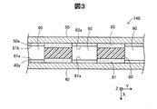
図3は、図2に示したアノード側セパレータ50のA−A断面を示す説明図である。図示するように、アノード側セパレータ50とカソード側セパレータ40との間には、前述した板状シール部材80が配置されている。板状シール部材80は、図1を用いて先に説明したように、両面に配置された接着層81,82によってセパレータ40,50に接着されている。また、板状シール部材80は、図2を用いて先に説明したように、複数本の連通孔90を備える。連通孔90が伸びる方向である前後方向Zは、図3において、表裏方向である。   FIG. 3 is an explanatory view showing an AA section of the anode-side separator 50 shown in FIG. As illustrated, the plate-shaped seal member 80 described above is disposed between the anode-side separator 50 and the cathode-side separator 40. As described above with reference to FIG. 1, the plate-like seal member 80 is bonded to the separators 40 and 50 by the adhesive layers 81 and 82 arranged on both surfaces. Further, the plate-like seal member 80 includes a plurality of communication holes 90 as described above with reference to FIG. The front-rear direction Z, which is the direction in which the communication hole 90 extends, is the front-back direction in FIG.

連通孔90の開口は、略矩形状である。連通孔90における積層方向Xの両側の内壁は、各セパレータ40,50のMEGA30側の面40a,50aによって構成される。これらの面40a,50aにおける連通孔90と対向する範囲に、薄膜層81a,82aが被覆されている。これによって、連通孔90におけるセパレータ40,50側の壁面は、薄膜層81a,82aによって覆われることになる。なお、図3に示した断面形状は、連通孔90の主要部の構成であり、連通孔90における、アノード側ガス拡散層33が配置される内部空間SPに近い側の部分では、口径のサイズが小さくなって内部空間SPに接続される。   The opening of the communication hole 90 is substantially rectangular. Inner walls on both sides of the communication hole 90 in the stacking direction X are configured by the MEGA 30 side surfaces 40 a and 50 a of the separators 40 and 50. The thin film layers 81a and 82a are covered in a range facing the communication holes 90 on these surfaces 40a and 50a. As a result, the wall surfaces on the separator 40, 50 side in the communication hole 90 are covered with the thin film layers 81a, 82a. The cross-sectional shape shown in FIG. 3 is the configuration of the main part of the communication hole 90. In the communication hole 90, the portion close to the internal space SP where the anode-side gas diffusion layer 33 is arranged is the size of the aperture. Becomes smaller and is connected to the internal space SP.

前述したように、各セパレータ40,50と板状シール部材80との間は、EPDM、エポキシ系、PIB等の接着剤によって接着されている。これら接着剤は、セパレータ40,50と板状シール部材80との間に塗布後、熱と荷重を付与することで、接着機能を発揮する(図4参照)。本実施形態では、製造時に付与する熱量、荷重、接着時間を、セパレータ40,50と板状シール部材80との間を単に接着するだけの場合に比べて大きくし、接着剤が、板状シール部材80とセパレータ40,50の間の部分(接着層81,82となる部分)から周囲へ溶け出し、連通孔90の両側から流れ出てきた接着剤がつながって、薄膜層81a,82aを形成するようにした。この結果、薄膜層81a,82aは、板状シール部材80と同じ材料で形成される。本実施形態では、薄膜層81a,82aの厚さが数十μmとなるように、熱量、荷重、接着時間を調整した。こうして形成された薄膜層81a,82aは、絶縁性、撥水性を有する。   As described above, the separators 40 and 50 and the plate-like seal member 80 are bonded with an adhesive such as EPDM, epoxy, or PIB. These adhesives exhibit an adhesive function by applying heat and a load after being applied between the separators 40 and 50 and the plate-like seal member 80 (see FIG. 4). In the present embodiment, the amount of heat, load, and bonding time applied at the time of manufacture are increased as compared with the case where the separators 40 and 50 and the plate-shaped seal member 80 are simply bonded, and the adhesive is used for the plate-shaped seal. The thin film layers 81a and 82a are formed by melting the portion between the member 80 and the separators 40 and 50 (portions that become the adhesive layers 81 and 82) to the surroundings and the adhesive flowing out from both sides of the communication hole 90 connected. I did it. As a result, the thin film layers 81 a and 82 a are formed of the same material as that of the plate-shaped sealing member 80. In the present embodiment, the amount of heat, the load, and the bonding time are adjusted so that the thickness of the thin film layers 81a and 82a is several tens of μm. The thin film layers 81a and 82a thus formed have insulating properties and water repellency.

アノード側ガス拡散層33と燃料ガス出口マニホールド64との間、酸化剤ガス入口マニホールド72とカソード側拡散層32との間、およびカソード側拡散層32と酸化剤ガス出口マニホールド74との間にも、図示しない連通孔が設けられている。これらの連通孔は、上述した燃料ガス入口マニホールド62とアノード側ガス拡散層33との間に設けた連通孔90と同様の構成であり、セパレータ40,50と対向する面に薄膜層(図示せず)が被覆されている。   Also between the anode side gas diffusion layer 33 and the fuel gas outlet manifold 64, between the oxidant gas inlet manifold 72 and the cathode side diffusion layer 32, and between the cathode side diffusion layer 32 and the oxidant gas outlet manifold 74. A communication hole (not shown) is provided. These communication holes have the same configuration as the communication hole 90 provided between the fuel gas inlet manifold 62 and the anode side gas diffusion layer 33 described above, and a thin film layer (not shown) is formed on the surface facing the separators 40 and 50. ) Is covered.

以上詳述したように、本実施形態の燃料電池スタック100によれば、アノード側ガス拡散層33が配置される内部空間と燃料ガス入口マニホールド62との間が、板状シール部材80に設けられた連通孔90によって結ばれ、セパレータ40,50のMEGA30側の面40a,50aにおける連通孔90と対向する範囲に、薄膜層81a,82aが被覆されている。このため、連通孔90に異物が侵入した場合に、セパレータ40,50の間が通電し、短絡することを防止できる。   As described in detail above, according to the fuel cell stack 100 of the present embodiment, the plate-shaped seal member 80 is provided between the internal space in which the anode-side gas diffusion layer 33 is disposed and the fuel gas inlet manifold 62. The thin film layers 81a and 82a are covered in a range facing the communication hole 90 on the surfaces 40a and 50a on the MEGA 30 side of the separators 40 and 50. For this reason, when a foreign material penetrates into the communication hole 90, it is possible to prevent the separators 40 and 50 from being energized and short-circuited.

また、燃料電池スタック100によれば、薄膜層81a,82aは撥水性を有することから、燃料電池スタック100排水性を向上することができる。さらに、燃料電池スタック100によれば、薄膜層81a,82aは、板状シール部材80を接着する接着層81,82と同じ材料とし、板状シール部材80とセパレータ40,50とを接合する工程において、薄膜層81a,82aが形成される構成としたことから、部品点数を増加することなく薄膜層81a,82aを形成することができる。このために、部品点数の削減、生産性の向上を図ることができる。   Further, according to the fuel cell stack 100, the thin film layers 81a and 82a have water repellency, so that the drainage of the fuel cell stack 100 can be improved. Furthermore, according to the fuel cell stack 100, the thin film layers 81a and 82a are made of the same material as the adhesive layers 81 and 82 to which the plate-like seal member 80 is bonded, and the plate-like seal member 80 and the separators 40 and 50 are joined. Since the thin film layers 81a and 82a are formed, the thin film layers 81a and 82a can be formed without increasing the number of parts. For this reason, the number of parts can be reduced and the productivity can be improved.

B.第2実施形態:
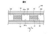
図5は、第2実施形態における燃料電池セル240の断面を示す説明図である。この断面は、図3に示したA−A断面と同じ位置の断面を示すものである。第2実施形態の燃料電池セル240は、第1実施形態の燃料電池セル140(図3)と比較して、薄膜層281a,282aの構成が相違し、残余の点で一致する。第2実施形態において第1実施形態と同一の構成要素については、第1実施形態と同一の符号を付けて説明を省略する。
B. Second embodiment:
FIG. 5 is an explanatory view showing a cross section of the fuel battery cell 240 according to the second embodiment. This cross section shows a cross section at the same position as the AA cross section shown in FIG. Compared with the fuel cell 140 (FIG. 3) of the first embodiment, the fuel cell 240 of the second embodiment differs in the configuration of the thin film layers 281a and 282a and matches in the remaining points. In the second embodiment, the same components as those of the first embodiment are denoted by the same reference numerals as those of the first embodiment, and description thereof is omitted.

薄膜層281a,282aは、第1実施形態における薄膜層81a,82aに対応するものである。第1実施形態では、薄膜層81a,82aは、連通孔90におけるセパレータ40,50と対向する面だけに配置されていたが、これに対して、第2実施形態では、連通孔290におけるセパレータ40,50と対向する面だけではなく、セパレータ40,50の互いに対向する面の全体に、薄膜層281a,282aが被覆されている。本実施形態では、薄膜層281a,282aとして、絶縁性、撥水性を有する薄シートが用いられている。これにより、板状シール部材80の接着層81,82は、薄膜層281a,282aを介在してセパレータ40,50と接合されている。   The thin film layers 281a and 282a correspond to the thin film layers 81a and 82a in the first embodiment. In the first embodiment, the thin film layers 81 a and 82 a are disposed only on the surface of the communication hole 90 facing the separators 40 and 50. On the other hand, in the second embodiment, the separator 40 in the communication hole 290. The thin film layers 281a and 282a are covered not only on the surface facing the surface 50, but also on the entire surfaces facing each other of the separators 40 and 50. In the present embodiment, thin sheets having insulating properties and water repellency are used as the thin film layers 281a and 282a. Thereby, the adhesive layers 81 and 82 of the plate-shaped sealing member 80 are joined to the separators 40 and 50 via the thin film layers 281a and 282a.

以上のように構成された第2実施形態の燃料電池セル240は、第1実施形態の燃料電池セル140と同様に、連通孔290に異物が侵入した場合に、セパレータ40,50の間が通電し、短絡することを防止できる。   The fuel cell 240 of the second embodiment configured as described above is energized between the separators 40 and 50 when a foreign object enters the communication hole 290, as in the fuel cell 140 of the first embodiment. Thus, it is possible to prevent a short circuit.

C.第3実施形態:
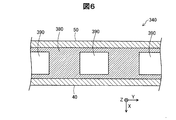
図6は、第3実施形態における燃料電池セル340の断面を示す説明図である。この断面は、図3に示したA−A断面と同じ位置の断面を示すものである。第3実施形態の燃料電池セル340は、第1実施形態の燃料電池セル140(図3)と比較して、シール部材380の構成が相違し、残余の点で一致する。第3実施形態において第1実施形態と同一の構成要素については、第1実施形態と同一の符号を付けて説明を省略する。
C. Third embodiment:
FIG. 6 is an explanatory view showing a cross section of the fuel battery cell 340 in the third embodiment. This cross section shows a cross section at the same position as the AA cross section shown in FIG. The fuel cell 340 of the third embodiment differs from the fuel cell 140 (FIG. 3) of the first embodiment in the configuration of the seal member 380 and matches the remaining points. In the third embodiment, the same components as those of the first embodiment are denoted by the same reference numerals as those of the first embodiment, and the description thereof is omitted.

シール部材380は、第1実施形態における板状シール部材80と接着層81,82と薄膜層81a,82aとに対応するもので、1部品によって構成される。シール部材380は、絶縁性、撥水性を有する材料によって形成されており、連通孔390を有する。連通孔390は、第1実施形態の連通孔90と同様に、アノード側ガス拡散層33が配置される内部空間と燃料ガス出口マニホールド64とを連通する。また、シール部材380は、各セパレータ40,50のMEGA10側の面における連通孔390と対向する範囲を被覆する。   The seal member 380 corresponds to the plate-like seal member 80, the adhesive layers 81 and 82, and the thin film layers 81a and 82a in the first embodiment, and is configured by one component. The seal member 380 is formed of a material having insulating properties and water repellency, and has a communication hole 390. Similar to the communication hole 90 of the first embodiment, the communication hole 390 communicates the internal space in which the anode-side gas diffusion layer 33 is disposed with the fuel gas outlet manifold 64. Further, the seal member 380 covers a range facing the communication hole 390 on the surface of the separators 40 and 50 on the MEGA 10 side.

以上のように構成された第3実施形態の燃料電池セル340は、第1実施形態の燃料電池セル140と同様に、連通孔390に異物が侵入した場合に、セパレータ40,50の間が通電し、短絡することを防止できる。   The fuel cell 340 of the third embodiment configured as described above is energized between the separators 40 and 50 when a foreign object enters the communication hole 390, like the fuel cell 140 of the first embodiment. Thus, it is possible to prevent a short circuit.

D.変形例:
前記各実施形態およびそれらの変形例では、カソード側セパレータ40のMEGA30側の面における連通孔と対向する範囲と、アノード側セパレータ50のMEGA30側の面における連通孔と対向する範囲との両方が絶縁性の材料によって被覆された。これに対して、変形例として、上記2つの範囲のうちのいずれか一方のみが絶縁性の材料によって被覆される構成としてもよい。
D. Variations:
In each of the embodiments and the modifications thereof, both the range facing the communication hole on the MEGA 30 side surface of the cathode side separator 40 and the range facing the communication hole on the MEGA 30 side surface of the anode side separator 50 are insulated. Coated with sex material. On the other hand, as a modification, only one of the two ranges may be covered with an insulating material.

本発明は、上述の実施形態に限られるものではなく、その趣旨を逸脱しない範囲において種々の構成で実現することができる。例えば、発明の概要の欄に記載した各形態中の技術的特徴に対応する実施形態中の技術的特徴は、上述の課題の一部又は全部を解決するために、あるいは、上述の効果の一部又は全部を達成するために、適宜、差し替えや、組み合わせを行うことが可能である。また、前述した各実施形態における構成要素の中の、独立請求項で記載された要素以外の要素は、付加的な要素であり、適宜省略可能である。   The present invention is not limited to the above-described embodiment, and can be realized with various configurations without departing from the spirit of the present invention. For example, the technical features in the embodiments corresponding to the technical features in each embodiment described in the summary section of the invention are intended to solve part or all of the above-described problems, or one of the above-described effects. In order to achieve part or all, replacement or combination can be appropriately performed. Moreover, elements other than the elements described in the independent claims among the constituent elements in the respective embodiments described above are additional elements and can be omitted as appropriate.

10…燃料電池システム
30…膜電極ガス拡散層接合体(MEGA)
31…膜電極接合体(MEA)
32…カソード側拡散層
33…アノード側ガス拡散層
40…カソード側セパレータ
42…酸化剤ガス流路溝
50…アノード側セパレータ
52…燃料ガス流路溝
54…冷却媒体流路溝
62…燃料ガス入口マニホールド
64…燃料ガス出口マニホールド
72…酸化剤ガス入口マニホールド
74…酸化剤ガス出口マニホールド
76…冷却媒体入口マニホールド
78…冷却媒体出口マニホールド
80…板状シール部材
81,82…接着層
81a,82a…薄膜層
90…連通孔
100…燃料電池スタック
110…エンドプレート
120…絶縁板
130…集電板
140…燃料電池セル
150…水素タンク
151…シャットバルブ
152…レギュレータ
153…配管
154…排出配管
160…エアポンプ
161…配管
163…排出配管
170…ラジエータ
171…ウォーターポンプ
172…配管
173…配管
190…冷却媒体流路面
240…燃料電池セル
281a,22a…薄膜層
290…連通孔
340…燃料電池セル
380…シール部材
390…連通孔
SP…内部空間
X…積層方向
Y…鉛直方向
Z…前後方向
DESCRIPTION OF SYMBOLS 10 ... Fuel cell system 30 ... Membrane electrode gas diffusion layer assembly (MEGA)
31 ... Membrane electrode assembly (MEA)
32 ... Cathode side diffusion layer 33 ... Anode side gas diffusion layer 40 ... Cathode side separator 42 ... Oxidant gas passage groove 50 ... Anode side separator 52 ... Fuel gas passage groove 54 ... Cooling medium passage groove 62 ... Fuel gas inlet Manifold 64 ... Fuel gas outlet manifold 72 ... Oxidant gas inlet manifold 74 ... Oxidant gas outlet manifold 76 ... Cooling medium inlet manifold 78 ... Cooling medium outlet manifold 80 ... Plate seal member 81, 82 ... Adhesive layer 81a, 82a ... Thin film Layer 90 ... Communication hole 100 ... Fuel cell stack 110 ... End plate 120 ... Insulating plate 130 ... Current collecting plate 140 ... Fuel cell 150 ... Hydrogen tank 151 ... Shut valve 152 ... Regulator 153 ... Pipe 154 ... Discharge pipe 160 ... Air pump 161 ... Piping 163 ... Discharge piping DESCRIPTION OF SYMBOLS 70 ... Radiator 171 ... Water pump 172 ... Piping 173 ... Piping 190 ... Cooling medium channel surface 240 ... Fuel cell 281a, 22a ... Thin film layer 290 ... Communication hole 340 ... Fuel cell 380 ... Seal member 390 ... Communication hole SP ... Inside Space X ... stacking direction Y ... vertical direction Z ... front-back direction

Claims (1)

燃料電池であって、
膜電極接合体と、前記膜電極接合体の両側に積層された第1および第2のガス拡散層と、を有する発電モジュールと、
前記発電モジュールの前記第1のガス拡散層側の面に沿って配置されるセパレータと、
前記セパレータの前記発電モジュール側の面における前記発電モジュールの外側に配置される板状のシール部材と、
を備え、
前記セパレータは、
前記発電モジュールと対向する位置より外側の位置に開口を備え、
前記板状のシール部材は、
前記開口と連通し、前記発電モジュールに反応ガスを分配するためのマニホールドを構成するマニホールド孔と、
前記第1のガス拡散層が配置される内部空間と前記マニホールド孔とを連通する連通孔と、
を備え、
前記セパレータの前記発電モジュール側の面における前記連通孔と対向する範囲に、絶縁性の材料が被覆された、
燃料電池。
A fuel cell,
A power generation module having a membrane electrode assembly, and first and second gas diffusion layers laminated on both sides of the membrane electrode assembly;
A separator disposed along a surface on the first gas diffusion layer side of the power generation module;
A plate-like sealing member disposed outside the power generation module on the power generation module side surface of the separator;
With
The separator is
An opening is provided at a position outside the position facing the power generation module,
The plate-like sealing member is
A manifold hole that communicates with the opening and forms a manifold for distributing reaction gas to the power generation module;
A communication hole communicating the internal space in which the first gas diffusion layer is disposed and the manifold hole;
With
In a range facing the communication hole on the power generation module side surface of the separator, an insulating material is coated,
Fuel cell.
JP2016002487A 2016-01-08 2016-01-08 Fuel cell Pending JP2017123301A (en)

Priority Applications (1)

Application Number Priority Date Filing Date Title
JP2016002487A JP2017123301A (en) 2016-01-08 2016-01-08 Fuel cell

Applications Claiming Priority (1)

Application Number Priority Date Filing Date Title
JP2016002487A JP2017123301A (en) 2016-01-08 2016-01-08 Fuel cell

Publications (1)

Publication Number Publication Date
JP2017123301A true JP2017123301A (en) 2017-07-13

Family

ID=59306657

Family Applications (1)

Application Number Title Priority Date Filing Date
JP2016002487A Pending JP2017123301A (en) 2016-01-08 2016-01-08 Fuel cell

Country Status (1)

Country Link
JP (1) JP2017123301A (en)

Similar Documents

Publication Publication Date Title
JP6402728B2 (en) Fuel cell and fuel cell manufacturing method
JP6258839B2 (en) Fuel cell separator, fuel cell current collector, fuel cell, and fuel cell stack
US9843055B2 (en) Separator for use in fuel cell, and fuel cell
WO2006101260A1 (en) Fuel cell and separator for fuel cell
US10340533B2 (en) Fuel cell stack
US20140162164A1 (en) Metal separator for fuel cell, fuel cell stack having the same and gasket assembly with fuel cell stack
JP4134731B2 (en) Fuel cell seal structure
JP2013500567A (en) Air-cooled metal separator for fuel cell and fuel cell stack using the same
JP2019153585A (en) Electrolyte membrane-electrode structure with frame and method of manufacturing the same, and fuel cell
CN109962259B (en) Fuel cell
WO2015072096A1 (en) Separator for fuel cell, and fuel cell stack
CN109950571B (en) Fuel cell
US10637077B2 (en) Frame equipped membrane electrode assembly and fuel cell
JP6843730B2 (en) Fuel cell and its operation method
JP2012212611A (en) Fuel battery cell
JP6349985B2 (en) Separator for fuel cell and fuel cell
JP2018181500A (en) Manufacturing method for fuel battery single cell
WO2007072671A1 (en) Sealing structure of fuel cell
JP2017123301A (en) Fuel cell
JP2018045882A (en) Fuel battery stack
JP2017117642A (en) Fuel battery
CN109524686B (en) Fuel cell separator, unit fuel cell, fuel cell stack, and electrode plate
JP2007042471A (en) Fuel cell stack
JP6870597B2 (en) Fuel cell
JP6569503B2 (en) Fuel cell seal structure