JP2017122941A - Manufacturing apparatus for spectacle lens and manufacturing for the same - Google Patents
Manufacturing apparatus for spectacle lens and manufacturing for the same Download PDFInfo
- Publication number
- JP2017122941A JP2017122941A JP2017079396A JP2017079396A JP2017122941A JP 2017122941 A JP2017122941 A JP 2017122941A JP 2017079396 A JP2017079396 A JP 2017079396A JP 2017079396 A JP2017079396 A JP 2017079396A JP 2017122941 A JP2017122941 A JP 2017122941A
- Authority
- JP
- Japan
- Prior art keywords
- lens
- prescription
- refractive
- distance
- view
- Prior art date
- Legal status (The legal status is an assumption and is not a legal conclusion. Google has not performed a legal analysis and makes no representation as to the accuracy of the status listed.)
- Granted
Links
- 238000004519 manufacturing process Methods 0.000 title claims description 37
- 238000009826 distribution Methods 0.000 claims abstract description 81
- 230000000750 progressive effect Effects 0.000 claims abstract description 65
- 238000012937 correction Methods 0.000 claims description 68
- 210000001508 eye Anatomy 0.000 claims description 44
- 238000000034 method Methods 0.000 claims description 18
- 230000009471 action Effects 0.000 claims description 12
- 230000008859 change Effects 0.000 claims description 10
- 230000008569 process Effects 0.000 claims description 8
- 230000004044 response Effects 0.000 claims description 4
- 238000012935 Averaging Methods 0.000 claims description 3
- 230000004438 eyesight Effects 0.000 abstract description 14
- 230000000007 visual effect Effects 0.000 abstract description 3
- 238000007792 addition Methods 0.000 description 62
- 238000013461 design Methods 0.000 description 42
- 238000012545 processing Methods 0.000 description 30
- 210000005252 bulbus oculi Anatomy 0.000 description 20
- 230000003287 optical effect Effects 0.000 description 15
- 230000005540 biological transmission Effects 0.000 description 14
- 230000000694 effects Effects 0.000 description 12
- 238000010586 diagram Methods 0.000 description 9
- 201000009310 astigmatism Diseases 0.000 description 7
- 238000012938 design process Methods 0.000 description 7
- 238000009472 formulation Methods 0.000 description 6
- 239000000203 mixture Substances 0.000 description 6
- 230000004075 alteration Effects 0.000 description 5
- 239000011521 glass Substances 0.000 description 5
- 238000000576 coating method Methods 0.000 description 4
- 239000011248 coating agent Substances 0.000 description 3
- 238000010276 construction Methods 0.000 description 3
- 238000012986 modification Methods 0.000 description 3
- 230000004048 modification Effects 0.000 description 3
- 208000001491 myopia Diseases 0.000 description 3
- 238000002834 transmittance Methods 0.000 description 3
- 206010020675 Hypermetropia Diseases 0.000 description 2
- 230000004308 accommodation Effects 0.000 description 2
- 238000013459 approach Methods 0.000 description 2
- 230000004323 axial length Effects 0.000 description 2
- 150000001875 compounds Chemical class 0.000 description 2
- 238000004043 dyeing Methods 0.000 description 2
- 230000004305 hyperopia Effects 0.000 description 2
- 201000006318 hyperopia Diseases 0.000 description 2
- 238000005304 joining Methods 0.000 description 2
- 239000000463 material Substances 0.000 description 2
- 230000004379 myopia Effects 0.000 description 2
- 208000014488 papillary tumor of the pineal region Diseases 0.000 description 2
- 230000002093 peripheral effect Effects 0.000 description 2
- 230000001179 pupillary effect Effects 0.000 description 2
- 230000009467 reduction Effects 0.000 description 2
- 102100024348 Beta-adducin Human genes 0.000 description 1
- 241000252203 Clupea harengus Species 0.000 description 1
- 101000689619 Homo sapiens Beta-adducin Proteins 0.000 description 1
- 230000006750 UV protection Effects 0.000 description 1
- 230000002542 deteriorative effect Effects 0.000 description 1
- 238000011156 evaluation Methods 0.000 description 1
- 235000019514 herring Nutrition 0.000 description 1
- 230000030214 innervation Effects 0.000 description 1
- 210000001747 pupil Anatomy 0.000 description 1
- 210000001525 retina Anatomy 0.000 description 1
- 230000001629 suppression Effects 0.000 description 1
- 230000004382 visual function Effects 0.000 description 1
Images


Classifications
-
- G—PHYSICS
- G02—OPTICS
- G02C—SPECTACLES; SUNGLASSES OR GOGGLES INSOFAR AS THEY HAVE THE SAME FEATURES AS SPECTACLES; CONTACT LENSES
- G02C7/00—Optical parts
- G02C7/02—Lenses; Lens systems ; Methods of designing lenses
- G02C7/024—Methods of designing ophthalmic lenses
- G02C7/027—Methods of designing ophthalmic lenses considering wearer's parameters
-
- G—PHYSICS
- G02—OPTICS
- G02C—SPECTACLES; SUNGLASSES OR GOGGLES INSOFAR AS THEY HAVE THE SAME FEATURES AS SPECTACLES; CONTACT LENSES
- G02C7/00—Optical parts
- G02C7/02—Lenses; Lens systems ; Methods of designing lenses
- G02C7/06—Lenses; Lens systems ; Methods of designing lenses bifocal; multifocal ; progressive
- G02C7/061—Spectacle lenses with progressively varying focal power
- G02C7/063—Shape of the progressive surface
- G02C7/065—Properties on the principal line
Landscapes
- Health & Medical Sciences (AREA)
- Ophthalmology & Optometry (AREA)
- Physics & Mathematics (AREA)
- General Health & Medical Sciences (AREA)
- General Physics & Mathematics (AREA)
- Optics & Photonics (AREA)
- Eyeglasses (AREA)
Abstract
Description
本発明は、第一の屈折力を有する第一屈折部、第一の屈折力よりも強い第二の屈折力を有する第二屈折部、及び第一屈折部から第二屈折部へ屈折力が累進的に変化する累進屈折部を有する眼鏡レンズの製造装置及び製造方法に関する。 The present invention provides a first refractive part having a first refractive power, a second refractive part having a second refractive power stronger than the first refractive power, and a refractive power from the first refractive part to the second refractive part. The present invention relates to a manufacturing apparatus and a manufacturing method of a spectacle lens having a progressive refraction section that changes progressively.
屈折力が累進的に変化する累進屈折部を有する眼鏡レンズが知られている。例えば遠近両用の累進屈折力レンズは、装用者が遠距離から近距離まで切れ目無く連続的に明視できるように主注視線上で度数が累進的に変化するデザインとなっている。この種の眼鏡レンズの多くは、左右眼の個々の処方度数や装用状態に応じて設計されているが、装用者が不同視の場合など、左右の遠用処方度数に差がある場合に好適な設計にはなっていなかった。なお、本明細書中、不同視は、その大小に拘わらず左右眼で度数差がある場合を指す。 A spectacle lens having a progressive refraction part in which the refractive power changes progressively is known. For example, a progressive-power lens for both near and far is designed such that the power gradually changes on the main line of sight so that the wearer can continuously and clearly see from a long distance to a short distance. Many of this type of spectacle lenses are designed according to the individual prescription powers and wearing conditions of the left and right eyes, but are suitable when there is a difference in the left and right distance prescription powers, such as when the wearer is blind. It was not designed properly. In addition, in this specification, non-congruent refers to the case where there is a frequency difference between the left and right eyes regardless of the size.
例えば、不同視の装用者は、遠用度数が左右で異なる眼鏡を装用したときに側方に位置する指標を両眼視すると、左右のレンズのプリズム作用の差に起因する左右の視線方向のずれを無くすため、調節緊張や調節弛緩を伴わない不自然な輻湊や開散を強いられていた。また、この種の輻湊や開散は、視線が通過するレンズ上の位置を設計上想定される位置から変えてしまうため、両眼に対する収差等を劣化させ、良好な両眼視を阻害する要因となっていた。 For example, a non-sighted wearer, who wears eyeglasses with different distance power on the left and right, sees the index located on the side when the glasses are worn in the left and right gaze directions due to the difference in the prism action of the left and right lenses. In order to eliminate the gap, unnatural convergence and spread without adjustment tension and relaxation were forced. In addition, this type of convergence or diverging changes the position on the lens through which the line of sight passes from the position assumed in the design, thus deteriorating aberrations and the like for both eyes and hindering good binocular vision It was.
そこで、米国特許第8,162,478号明細書(以下、「特許文献1」と記す。)に、遠用度数が左右で異なる一対の累進屈折力レンズにおいて、良好な両眼視を保証するものが提案されている。具体的には、特許文献1には、遠用度数が左右で異なる一対の累進屈折力レンズのレンズ成分を、遠用度数と加入度数とが左右で等しい一対の累進屈折力レンズ成分と、左右異なる度数の一対の単焦点レンズ成分とに分け、単焦点レンズ成分を有するレンズを装用して両眼視をする場合に、正面遠方から所定の方位角に向かって正面以外の遠方に視線を移すときの左右眼のレンズ上の視線移動距離の比率を算出し、累進屈折力レンズ成分を有するレンズの片眼用又は両眼用のレンズ成分の平均度数分布及び非点収差分布に対し、その比率に応じた補正を加えることにより、両眼視における左右の視線に対する平均度数及び非点収差の差において、左右の遠用度数差以外の収差の発生を抑制する、という技術が開示されている。
Therefore, in US Pat. No. 8,162,478 (hereinafter referred to as “
このように、特許文献1には、遠用度数が左右で異なる一対の累進屈折力レンズにおいて、左右夫々の視線に対する収差の差を低減することで、良好な両眼視を保証するものが提案されている。しかし、良好な両眼視をより一層高いレベルで保証したいという要望は恒常的に存在する。そこで、本発明者は、鋭意検討を重ねた結果、良好な両眼視をより一層高いレベルで保証するのに好適な眼鏡レンズの製造装置及び製造方法を見出した。
As described above,
本発明の一形態に係る眼鏡レンズの製造装置は、第一の屈折力を有する第一屈折部、第一の屈折力よりも強い第二の屈折力を有する第二屈折部、及び第一屈折部から第二屈折部へ屈折力が累進的に変化する累進屈折部を有する、第一の屈折力が左右で異なる一対の眼鏡レンズを製造する装置であり、所定の処方情報に基づき、生理的に左右眼の調節力が等しくなることに対応して左右共通の基準レンズを定義する基準レンズ定義手段と、基準レンズ上の所定の各サンプル点を通過する光線の物体側画角を計算する画角計算手段と、処方情報に基づく左右夫々の処方レンズ上の光線通過位置であって、処方レンズにおける物体側画角が画角計算手段にて求められた物体側画角と一致する光線を計算することにより、基準レンズ上の各サンプル点に対応する光線と同じ物体側画角を持つ光線が通過する処方レンズ上の夫々の位置を求める処方側通過位置計算手段と、正面視の視線と基準レンズとの交点と、基準レンズ上のサンプル点との距離を第一の距離と定義し、正面視の視線と処方レンズとの交点と、処方レンズ上の光線通過位置との距離を第二の距離と定義した場合に、左右夫々について、各物体側画角に対応する、第一の距離と第二の距離との比率を計算する比率計算手段と、左右夫々について、各物体側画角に対応する処方レンズ上の光線通過位置における曲率を比率に基づいて補正することにより、処方レンズの曲率分布を補正する曲率分布補正手段とを備える。 An eyeglass lens manufacturing apparatus according to an aspect of the present invention includes a first refractive part having a first refractive power, a second refractive part having a second refractive power stronger than the first refractive power, and a first refractive part. This is an apparatus for manufacturing a pair of spectacle lenses having a first refractive power different on the left and right, having a progressive refractive part in which the refractive power gradually changes from the first to the second refractive part, and based on predetermined prescription information A reference lens defining means for defining a common reference lens for the left and right in correspondence with the equal adjustment power of the left and right eyes, and an image for calculating the object-side angle of view of light rays passing through each predetermined sample point on the reference lens. The angle calculation means and the light beam passing positions on the left and right prescription lenses based on the prescription information, where the object side angle of view of the prescription lens matches the object side angle of view obtained by the angle of view calculation means Each sample point on the reference lens by Prescription-side passing position calculation means for obtaining respective positions on the prescription lens through which light rays having the same object-side angle of view as the corresponding light rays pass, intersection points between the line of sight of the front view and the reference lens, and sample points on the reference lens Is defined as the first distance, and the intersection between the line of sight of the front view and the prescription lens and the distance between the light beam passing position on the prescription lens is defined as the second distance, The ratio calculation means for calculating the ratio between the first distance and the second distance corresponding to the object side angle of view, and the curvature at the light beam passing position on the prescription lens corresponding to each object side angle of view for each of the left and right. Curvature distribution correcting means for correcting the curvature distribution of the prescription lens by correcting based on the ratio.
本発明の一形態に係る眼鏡レンズの製造装置によれば、第一屈折部から第二屈折部にかけての主注視線上において装用者の左右の眼に実質的に作用する加入効果の差が抑えられた眼鏡レンズが製造される。これにより、左右夫々の眼に必要な調節力を同程度に保つことができ、この場合、両眼での良好な中間視及び近方視が達成される。また、このように製造された眼鏡レンズでは、左右夫々の視線上の収差の差が低減されているので、左右眼夫々の網膜上に形成される像の質を同程度にすることができ、両眼視機能を阻害する要因の抑制が達成される。これにより、例えば遠方から近方に至るまでの各物体距離で良好な両眼視を保証することが可能となる。 According to the spectacle lens manufacturing apparatus according to an aspect of the present invention, the difference in the addition effect that substantially acts on the left and right eyes of the wearer on the main gazing line from the first refraction part to the second refraction part can be suppressed. Eyeglass lenses are manufactured. Thereby, it is possible to maintain the same adjustment force necessary for the left and right eyes. In this case, good intermediate vision and near vision with both eyes are achieved. Further, in the eyeglass lens manufactured in this way, the difference in aberrations on the left and right eyes is reduced, so that the quality of the images formed on the retinas of the left and right eyes can be made comparable, Suppression of factors that inhibit binocular visual function is achieved. Thereby, for example, it is possible to ensure good binocular vision at each object distance from far to near.
各物体側画角に対応する、第一の距離と第二の距離との比率は、例えば、処方レンズにおける第一の屈折力が基準レンズにおける第一の屈折力よりもマイナス側の場合、1よりも小さい値となり、かつ均一ではない。 The ratio between the first distance and the second distance corresponding to each object-side field angle is, for example, 1 when the first refractive power in the prescription lens is more negative than the first refractive power in the reference lens. It is a smaller value and is not uniform.
各物体側画角に対応する、第一の距離と第二の距離との比率はまた、例えば、処方レンズにおける第一の屈折力が基準レンズにおける第一の屈折力よりもプラス側の場合、1よりも大きい値となり、かつ均一ではない。 The ratio between the first distance and the second distance corresponding to each object-side angle of view is also, for example, when the first refractive power in the prescription lens is more positive than the first refractive power in the reference lens, The value is larger than 1 and is not uniform.
また、本発明の一形態に係る眼鏡レンズの製造装置は、基準レンズにおける第二の屈折部での加入度を計算する第一の加入度計算手段と、曲率分布補正手段による曲率分布補正後の左右の処方レンズの夫々における第二の屈折部での加入度を計算する第二の加入度計算手段と、第二の加入度計算手段で計算された加入度を第一の加入度計算手段で計算された加入度と一致させるように、曲率分布補正後の左右の処方レンズの曲率分布の夫々を更に補正する加入度補正手段とを備えるものとしてもよい。 The spectacle lens manufacturing apparatus according to an aspect of the present invention includes a first addition calculation unit that calculates the addition at the second refractive portion of the reference lens, and a curvature distribution corrected by the curvature distribution correction unit. A second addition calculating means for calculating the addition at the second refracting portion in each of the left and right prescription lenses, and the addition calculated by the second addition calculating means by the first addition calculating means. An addition correction means for further correcting each of the curvature distributions of the left and right prescription lenses after the curvature distribution correction may be provided so as to coincide with the calculated addition.
基準レンズは、例えば、処方情報に基づいて決定される左右共通の遠用度数及び加入度数を有している。このとき、遠用度数は、左右の遠用処方度数を平均した度数となる。 The reference lens has, for example, a distance diopter and a diopter common to the left and right determined based on prescription information. At this time, the distance power is a frequency obtained by averaging the left and right distance prescription powers.
本発明の一形態に係る眼鏡レンズの製造方法は、第一の屈折力を有する第一屈折部、第一の屈折力よりも強い第二の屈折力を有する第二屈折部、及び第一屈折部から第二屈折部へ屈折力が累進的に変化する累進屈折部を有する、第一の屈折力が左右で異なる一対の眼鏡レンズを製造する方法であり、所定の処方情報に基づき、生理的に左右眼の調節力が等しくなることに対応して左右共通の基準レンズを定義する基準レンズ定義工程と、基準レンズ上の所定の各サンプル点を通過する光線の物体側画角を計算する画角計算工程と、処方情報に基づく左右夫々の処方レンズ上の光線通過位置であって、処方レンズにおける物体側画角が画角計算工程にて求められた物体側画角と一致する光線を計算することにより、基準レンズ上の各サンプル点に対応する光線と同じ物体側画角を持つ光線が通過する処方レンズ上の夫々の位置を求める処方側通過位置計算工程と、正面視の視線と基準レンズとの交点と、基準レンズ上のサンプル点との距離を第一の距離と定義し、正面視の視線と処方レンズとの交点と、処方レンズ上の光線通過位置との距離を第二の距離と定義した場合に、左右夫々について、各物体側画角に対応する、第一の距離と第二の距離との比率を計算する比率計算工程と、左右夫々について、各物体側画角に対応する処方レンズ上の光線通過位置における曲率を比率に基づいて補正することにより、処方レンズの曲率分布を補正する曲率分布補正工程とを含む。 A spectacle lens manufacturing method according to an aspect of the present invention includes a first refractive part having a first refractive power, a second refractive part having a second refractive power stronger than the first refractive power, and a first refractive part. Is a method of manufacturing a pair of spectacle lenses having a first refractive power different on the left and right, having a progressive refractive part in which the refractive power gradually changes from the first refractive part to the second refractive part, and based on predetermined prescription information A reference lens definition step for defining a common reference lens for the left and right in response to the equal adjustment power of the left and right eyes, and an image for calculating the object-side angle of view of light rays passing through each predetermined sample point on the reference lens. Calculates the light ray passing positions on the left and right prescription lenses based on the prescription information and the object side angle of view of the prescription lens that matches the object side angle of view obtained in the view angle calculation step based on the prescription information. Each sample point on the reference lens by Prescription-side passing position calculation process for determining each position on the prescription lens through which a light beam having the same object-side angle of view as the corresponding light beam passes, the intersection of the line of sight of the front view and the reference lens, and the sample point on the reference lens Is defined as the first distance, and the intersection between the line of sight of the front view and the prescription lens and the distance between the light beam passing position on the prescription lens is defined as the second distance, The ratio calculation step for calculating the ratio between the first distance and the second distance corresponding to the object-side field angle, and the curvature at the light beam passing position on the prescription lens corresponding to each object-side field angle for each of the left and right sides. A curvature distribution correcting step of correcting the curvature distribution of the prescription lens by correcting based on the ratio.
本発明の一形態に係る眼鏡レンズの製造装置及び製造方法によれば、第一屈折部から第二屈折部にかけての主注視線上において装用者の左右の眼に実質的に作用する加入効果の差が抑えられると共に、左右夫々の視線上の収差の差が抑えられるため、例えば遠方から近方に至るまでの各物体距離で良好な両眼視を保証することが可能な眼鏡レンズが提供される。 According to the spectacle lens manufacturing apparatus and method according to an aspect of the present invention, the difference in the addition effect that substantially acts on the left and right eyes of the wearer on the main line of sight from the first refracting portion to the second refracting portion. And a difference in aberrations on the left and right line of sight can be suppressed, and for example, a spectacle lens that can guarantee good binocular vision at each object distance from far to near is provided. .
以下、図面を参照して、本発明の実施形態に係る眼鏡レンズ製造システムについて説明する。 A spectacle lens manufacturing system according to an embodiment of the present invention will be described below with reference to the drawings.
[眼鏡レンズ製造システム1]
図1は、本実施形態の眼鏡レンズ製造システム1の構成を示すブロック図である。図1に示されるように、眼鏡レンズ製造システム1は、顧客(装用者)に対する処方に応じた眼鏡レンズを発注する眼鏡店10と、眼鏡店10からの発注を受けて眼鏡レンズを製造する眼鏡レンズ製造工場20を有している。眼鏡レンズ製造工場20への発注は、インターネット等の所定のネットワークやFAX等によるデータ送信を通じて行われる。発注者には眼科医や一般消費者を含めてもよい。
[Eyeglass lens manufacturing system 1]
FIG. 1 is a block diagram illustrating a configuration of a spectacle
[眼鏡店10]
眼鏡店10には、店頭コンピュータ100が設置されている。店頭コンピュータ100は、例えば一般的なPC(Personal Computer)であり、眼鏡レンズ製造工場20への眼鏡レンズの発注を行うためのソフトウェアがインストールされている。店頭コンピュータ100には、眼鏡店スタッフによるマウスやキーボード等の操作を通じてレンズデータ及びフレームデータが入力される。レンズデータには、例えば処方値(ベースカーブ、球面屈折力、乱視屈折力、乱視軸方向、プリズム屈折力、プリズム基底方向、加入度数、瞳孔間距離(PD:Pupillary Distance)等)、眼鏡レンズの装用条件(角膜頂点間距離、前傾角、フレームあおり角)、眼鏡レンズの種類(単焦点球面、単焦点非球面、多焦点(二重焦点、累進)、コーティング(染色加工、ハードコート、反射防止膜、紫外線カット等))、顧客の要望に応じたレイアウトデータ等が含まれる。フレームデータには、顧客が選択したフレームの形状データが含まれる。フレームデータは、例えばバーコードタグで管理されており、バーコードリーダによるフレームに貼り付けられたバーコードタグの読み取りを通じて入手することができる。店頭コンピュータ100は、発注データ(レンズデータ及びフレームデータ)を例えばインターネット経由で眼鏡レンズ製造工場20に送信する。
[Optical store 10]
The
[眼鏡レンズ製造工場20]
眼鏡レンズ製造工場20には、ホストコンピュータ200を中心としたLAN(Local Area Network)が構築されており、眼鏡レンズ設計用コンピュータ202や眼鏡レンズ加工用コンピュータ204をはじめ多数の端末装置が接続されている。眼鏡レンズ設計用コンピュータ202、眼鏡レンズ加工用コンピュータ204は一般的なPCであり、それぞれ、眼鏡レンズ設計用のプログラム、眼鏡レンズ加工用のプログラムがインストールされている。ホストコンピュータ200には、店頭コンピュータ100からインターネット経由で送信された発注データが入力される。ホストコンピュータ200は、入力された発注データを眼鏡レンズ設計用コンピュータ202に送信する。
[Glasses lens manufacturing factory 20]
In the spectacle
眼鏡レンズ製造工場20では、発注データを受けた後、未加工のブロックピースに対し、装用者の処方が満たされるように、内面、外面の両面の設計及び加工が行われる。なお、眼鏡レンズ製造工場20では、生産性を向上させるため、全製作範囲の度数を複数のグループに区分し、各グループの度数範囲に適合した外面(凸面)カーブ形状(球面形状又は非球面形状)とレンズ径を有するセミフィニッシュトブランクが眼鏡レンズの注文に備えて予め用意されていてもよい。この場合、眼鏡レンズ製造工場20では、内面(凹面)加工(及び玉型加工)を行うだけで、装用者の処方に適した眼鏡レンズが製造される。
After receiving the ordering data, the spectacle
眼鏡レンズ設計用コンピュータ202は、受注に応じた眼鏡レンズを設計するためのプログラムがインストールされており、発注データ(レンズデータ)に基づいてレンズ設計データを作成し、発注データ(フレームデータ)に基づいて玉型加工データを作成する。眼鏡レンズ設計用コンピュータ202による眼鏡レンズの設計は、後に詳細に説明する。眼鏡レンズ設計用コンピュータ202は、作成したレンズ設計データ及び玉型加工データを眼鏡レンズ加工用コンピュータ204に転送する。
The eyeglass
オペレータは、ブロックピースをカーブジェネレータ等の加工機206にセットして、眼鏡レンズ加工用コンピュータ204に対して加工開始の指示入力を行う。眼鏡レンズ加工用コンピュータ204は、眼鏡レンズ設計用コンピュータ202から転送されたレンズ設計データ及び玉型加工データを読み込み、加工機206を駆動制御する。加工機206は、ブロックピースの内面及び外面をレンズ設計データに従って研削・研磨して、眼鏡レンズの内面形状及び外面形状を作製する。また、加工機206は、内面形状及び外面形状作製後のアンカットレンズの外周面を玉型形状に対応した周縁形状に加工する。
The operator sets the block piece on the
玉型加工後の眼鏡レンズには、発注データに従い、染色加工、ハードコート加工、反射防止膜、紫外線カット等の各種コーティングが施される。これにより、眼鏡レンズが完成して眼鏡店10に納品される。
The eyeglass lens after the lens processing is subjected to various coatings such as dyeing, hard coating, antireflection film, and UV protection according to the order data. Thereby, the spectacle lens is completed and delivered to the
[眼鏡レンズ設計用コンピュータ202による眼鏡レンズの具体的設計方法]
図2は、眼鏡レンズ設計用コンピュータ202による眼鏡レンズの設計工程を示すフローチャートである。以下の説明では、不同視の装用者に処方すべき、遠用度数が左右で異なる一対の眼鏡レンズであり、累進屈折要素を内面若しくは外面に持つ片面累進型、又は累進屈折要素を外面と内面の両面に配分した両面累進型、又は縦方向の累進屈折要素を外面に配分し、横方向の累進屈折要素を内面に配分した両面複合累進型の、遠近両用の各種眼鏡レンズの設計を想定する。しかし、本設計工程は、所定の基準点における度数が左右で異なる一対の眼鏡レンズであり、片面累進型、両面累進型又は両面複合累進型の中近両用累進屈折力レンズや近々累進屈折力レンズなど、屈折力が累進的に変化する累進屈折部を有する他のアイテム群の眼鏡レンズにも適用することができる。
[Specific Eyeglass Lens Design Method Using Eyeglass Lens Design Computer 202]
FIG. 2 is a flowchart showing a spectacle lens design process performed by the spectacle
また、眼光学上、厳密には、眼軸と視線の向きは僅かに異なるが、その差異による影響は実質的に無視できる程度である。そのため、本明細書においては、説明の便宜上、眼軸と視線の向きは眼光学上も一致するものと擬制し、眼軸と視線の向きとの相違はレンズのプリズム作用によってのみ引き起こされる前提とする。 In terms of ophthalmic optics, strictly speaking, the direction of the eye axis and the line of sight are slightly different, but the influence of the difference is substantially negligible. Therefore, in this specification, for convenience of explanation, it is assumed that the direction of the eye axis and the line of sight coincide with each other in terms of eye optics, and the difference between the direction of the eye axis and the line of sight is assumed to be caused only by the prism action of the lens. To do.
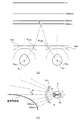
ここで、図12を用いて、遠用度数が左右で異なる一対の眼鏡レンズにて発生する問題点を説明する。図12では、不同視の装用者が次の処方度数の眼鏡レンズを通して近方物点を両眼視する状態を示す。
処方度数(右):S+2.00 ADD2.50
処方度数(左):S+4.00 ADD2.50
なお、図12では、便宜上、左右の眼鏡レンズを1枚の共通形状のレンズにて示すが、実際には、左右の眼鏡レンズは処方度数に応じて形状が異なる。
Here, with reference to FIG. 12, a problem that occurs in a pair of spectacle lenses having different distance powers on the left and right will be described. FIG. 12 shows a state in which a non-sighted wearer views a near object point through a spectacle lens having the following prescription power.
Prescription frequency (right): S + 2.00 ADD2.50
Prescription frequency (left): S + 4.00 ADD2.50
In FIG. 12, for the sake of convenience, the left and right eyeglass lenses are shown as a single lens having a common shape, but in actuality, the left and right eyeglass lenses have different shapes depending on the prescription power.
図12に示されるように、不同視の装用者が近方物点を両眼視するとき、処方度数差に応じた左右のプリズム作用の差に起因して、左右の視線方向にずれが生じる。具体的には、装用者は、レンズ上にレイアウトされた近用基準点N(近用部の度数が設定される、加入度数が2.50Dの点)以外の点を通じて近方物点を両眼視することになる。図12の例では、右眼は、近用基準点Nよりも上方の点PU(加入度数が2.50Dを下回る点)を通じて近方物点に視線を向け、左眼は、近用基準点Nよりも下方の点PD(加入度数が2.50D又は2.50Dを上回る点)を通じて近方物点に視線を向ける。このように、左右の視線方向がずれることにより、左右の眼に実質的に作用する加入効果が異なる。そのため、理論上、左右の眼に対して異なる調節力が要求される。しかし、生理的には、左右の眼に働く調節力は常に等しい(ヘリングの等量神経支配の法則(Hering's law of equal innervation))。従って、装用者は、左右の眼に実質的に作用する加入効果が異なるという、眼に負担のかかる状態で近方物点を視ることを余儀なくされる。本明細書では、説明の便宜上、眼に実質的に作用する加入効果を「実質加入度」とも表現する。 As shown in FIG. 12, when a non-homogeneous wearer views a near object point in both eyes, a shift occurs in the left and right gaze directions due to the difference in the left and right prism action according to the prescription power difference. . Specifically, the wearer places both near object points through points other than the near reference point N laid out on the lens (the power of the near portion is set and the addition power is 2.50D). You will see it visually. In the example of FIG. 12, the right eye directs its line of sight toward the near object point through a point P U (a point where the addition power is less than 2.50D) above the near reference point N, and the left eye uses the near reference point. A line of sight is directed to a near object point through a point P D below the point N (a point where the addition power exceeds 2.50D or 2.50D). In this way, the addition effect that substantially acts on the left and right eyes varies depending on the deviation of the left and right gaze directions. Therefore, theoretically, different accommodation powers are required for the left and right eyes. However, physiologically, the accommodation forces acting on the left and right eyes are always equal (Herring's law of equal innervation). Therefore, the wearer is forced to view the near object point in a state where the effect of joining which acts substantially on the left and right eyes is different and the eye is burdened. In the present specification, for the convenience of explanation, the addition effect that substantially acts on the eye is also expressed as “substantial addition degree”.
本発明者は、鋭意検討を重ねた結果、左右の遠用処方度数が異なるほど、また、物体距離が近いほど左右の実質加入度の差が大きくなることを見出し、図12では、左右の実質加入度の差が大きくなる例として近方物点を視る状態を示した。すなわち、本発明者は、上記問題が近方だけでなく、近方よりも離れた距離(例えば遠方や中間距離等)においても発生することを見出している。本実施形態では、以下に説明する設計工程を実施することにより、上記問題を解消して良好な両眼視を各物体距離(例えば遠方から近方に至るまで)で保証することが可能な眼鏡レンズが設計される。以下、図2を用いて、眼鏡レンズ設計用コンピュータ202による眼鏡レンズの設計工程を具体的に説明する。
As a result of intensive studies, the present inventor found that the difference in the left and right distance prescription powers and the closer the object distance, the larger the difference in the left and right substantial addition power. In FIG. As an example of the difference in addition, the state of viewing near object points is shown. That is, the present inventor has found that the above problem occurs not only in the near field but also in a distance (for example, a far distance or an intermediate distance) that is further away from the near field. In the present embodiment, by performing the design process described below, glasses that can solve the above problem and guarantee good binocular vision at each object distance (for example, from far to near). A lens is designed. Hereinafter, the spectacle lens design process by the spectacle
[図2のS1(基準レンズの定義)]
眼鏡レンズ設計用コンピュータ202は、ホストコンピュータ200を介して店頭コンピュータ100より受信した装用者の処方値に基づいて基準レンズを定義する。基準レンズは、生理的に左右眼の調節力が等しくなることに対応して、仮想的に定義される左右共通の眼鏡レンズであり、遠用度数が左右の遠用処方度数を平均した値に設定される。すなわち、基準レンズは累進屈折部を持つ眼鏡レンズであり、左右で共通の遠用度数及び加入度数を有するものである。以下、基準レンズの遠用度数を基準度数と定義する。例えば、
処方度数(右):S+2.00 ADD2.50
処方度数(左):S+4.00 ADD2.50
の場合、基準レンズは、
基準度数(右):S+3.00 ADD2.50
基準度数(左):S+3.00 ADD2.50
となる。なお、本実施形態では、右眼用レンズと左眼用レンズとが並行して設計される手順で説明するが、別の実施形態では、一方のレンズが設計され、その後、他方のレンズが設計される手順としてもよい。
[S1 in FIG. 2 (Definition of Reference Lens)]
The spectacle
Prescription frequency (right): S + 2.00 ADD2.50
Prescription frequency (left): S + 4.00 ADD2.50
In the case of
Reference frequency (right): S + 3.00 ADD2.50
Reference frequency (left): S + 3.00 ADD2.50
It becomes. In this embodiment, the procedure for designing the right-eye lens and the left-eye lens in parallel will be described. However, in another embodiment, one lens is designed, and then the other lens is designed. It is good also as a procedure to be performed.
[図2のS2(基準レンズに対応する仮想光学モデルの構築)]
眼鏡レンズ設計用コンピュータ202は、装用者が眼鏡レンズ(基準レンズ:S+3.00 ADD2.50)を装用した状態を想定した、眼球及び眼鏡レンズからなる所定の仮想光学モデルを構築する。図3(a)は、眼鏡レンズ設計用コンピュータ202によって構築される仮想光学モデル例を示す。なお、以降の説明において、右眼に対応する符号には下付き文字Rを付し、左眼に対応する符号には下付き文字Lを付す。また、左右両方の眼に対応する説明には、これらの下付き文字を付さない。
[S2 in FIG. 2 (Construction of virtual optical model corresponding to reference lens)]
The spectacle
眼球の眼軸長は、遠視、近視で異なる。そこで、眼鏡レンズ設計用コンピュータ202は、遠視、近視の度合いで眼軸長がどれだけ異なるかを予め記憶している。その中から、眼鏡レンズ設計用コンピュータ202は、発注データに含まれる装用者の処方値(球面屈折力、乱視屈折力)に従って適切な眼球モデルEを選択し、図3(a)に示されるように、選択された眼球モデルEを仮想モデル空間に配置する。より詳細には、眼球モデルERと眼球モデルELは、眼球回旋中心OERと眼球回旋中心OELとが瞳孔間距離PDだけ離れた位置に配置される。
The axial length of the eyeball differs between hyperopia and myopia. Therefore, the spectacle
眼鏡レンズ設計用コンピュータ202は、眼球モデルER、ELの夫々に対して所定の角膜頂点間距離CVDR、CVDLを空けた位置に、基準レンズに対応する基準レンズモデルLBR、LBLを配置する。角膜頂点間距離CVDは、基準レンズモデルLBの後方頂点と眼球モデルEの角膜頂点との距離であり、例えば12.5mmである。なお、基準レンズモデルLBの中心肉厚は、処方値や硝材の屈折率等に基づいて決定される。また、基準レンズモデルLBは、眼鏡レンズの傾き(前傾角、フレームあおり角)を考慮して仮想モデル空間に配置されてもよい。また、説明の便宜上、基準レンズモデルLBの外面頂点での接平面を接平面TPと定義し、眼球モデルERの正面視の視線と接平面TPとの交点を基準点PTPRと定義し、眼球モデルELの正面視の視線と接平面TPとの交点を基準点PTPLと定義する。これらの基準点PTPはレンズ設計中心にあり、設計中心は一対の隠しマーク(後述)の中間点である。
The eyeglass
図3(b)に、本設計工程にて設計される眼鏡レンズのレイアウトを概略的に示す。図3(b)に示されるように、本実施形態による眼鏡レンズは、主注視線LL’上であって、レンズ設計中心の上方に遠用基準点F(遠用部の度数が設定される点)が配置され、レンズ設計中心の下方に近用基準点Nが配置される。主注視線LL’は、累進帯の途中から近用基準点Nに向かい、眼の輻輳を考慮して鼻側へインセットされている。近用基準点N及び遠用基準点Fの位置は、レンズ面に直接刻印される一対の隠しマークMを基に特定される。本実施形態による眼鏡レンズは、後述するように、累進帯の長さ及び幅が左右で異なるため、近用基準点N及び遠用基準点Fのレンズ面上の位置も左右で異なる。 FIG. 3B schematically shows the layout of the spectacle lens designed in this design process. As shown in FIG. 3B, the spectacle lens according to the present embodiment is on the main line of sight LL ′, and the distance reference point F (the power of the distance portion is set above the lens design center). Point) and a near reference point N is arranged below the lens design center. The main gazing line LL 'is directed from the middle of the progressive zone toward the near reference point N and is inset to the nose side in consideration of eye convergence. The positions of the near reference point N and the far reference point F are specified based on a pair of hidden marks M that are directly engraved on the lens surface. As will be described later, since the length and width of the progressive zone are different on the right and left, the spectacle lens according to the present embodiment also has different positions on the lens surface of the near reference point N and the far reference point F.
[図2のS3(基準レンズモデルLBにおける物体側画角βの計算)]
図4(a)、図4(b)は夫々、基準レンズモデルLBR、LBLの各点を通過する光線の物体側画角β(単位:°)を示す図である。なお、図4以降の仮想光学モデルを示す各図においては、眼球モデルEを頭上から眺める角度(図3(a)参照)で示さず、説明の便宜上、眼球モデルEを側面から眺める角度(眼球モデルER、ELの何れにおいても主注視線LL’が紙面と平行になり、かつ近用基準点Nが下側に位置すると共に遠用基準点Fが上側に位置する角度)で示す。物体側画角βは、図4(a)、図4(b)の各図に示されるように、正面視したときの水平軸を基準とする。
[(Calculation of the object-side angle β in reference lens model L B) S3 of FIG. 2]
FIG. 4A and FIG. 4B are diagrams showing the object-side field angle β (unit: °) of light rays passing through the points of the reference lens models L BR and L BL , respectively. In each of the drawings showing the virtual optical model in FIG. 4 and subsequent figures, the angle when the eyeball model E is viewed from the side (see FIG. 3A) is not shown. For convenience of explanation, the angle when the eyeball model E is viewed from the side (eyeball) In both models E R and E L, the main gazing line LL ′ is parallel to the paper surface, and the near reference point N is located on the lower side and the far reference point F is located on the upper side). The object-side angle of view β is based on the horizontal axis when viewed from the front, as shown in FIGS. 4 (a) and 4 (b).
眼鏡レンズ設計用コンピュータ202は、光線追跡等を用いた光学計算処理を行うことにより、基準レンズモデルLB上(ここではレンズ外面上)のサンプル点Sを通過する光線の物体側画角βを計算する。ここで、本工程の実施にあたり、眼球回旋中心OE及び基準レンズモデルLBが既に定められているため、光線が通過する基準レンズモデルLB上の位置が決まることにより、その光線の基準レンズモデルLBにおける物体側画角βが一義的に求まる。そこで、本実施形態では、予め定められた基準レンズモデルLB上の各サンプル点Sについて物体側画角βを計算する。サンプル点Sは、例えば基準レンズモデルLBの全面に等間隔ピッチで配置されている。但し、サンプル点Sは等間隔ピッチでの配置に限らず、例えば主注視線LL’を含む明視域に密に配置され、使用頻度の低い側方域に疎に配置されるなど、領域毎に異なる重みで配置されてもよい。なお、本工程以降の工程では、便宜上、原則、各種レンズモデルの外面にのみ曲率分布(透過度数分布に対応する曲率分布)が存在するものとしてレンズ設計が行われるものとする。
Eyeglass
図4(a)、図4(b)の各図においては、主注視線LL’上の各度数に対応するサンプル点Sを通過する光線の物体側画角βを示している。基準レンズモデルLBにおいて、近用基準点Nは、例えば基準点PTPより14mm下に位置する点であり、装用者が近業目的距離(目的とする近方の作業距離であり、例えば400mm)を視るための点である。そのため、近用基準点Nを通過する光線の物体側画角βは、近業目的距離に対応する画角として定義することができる。他のサンプル点Sを通過する光線の物体側画角βについても同様に、サンプル点Sにて想定される物体距離に対応する画角として定義することができる。 In each of FIGS. 4A and 4B, the object-side angle of view β of the light beam passing through the sample point S corresponding to each power on the main gazing line LL ′ is shown. In the reference lens model L B, the reference point N for near, for example a point located 14mm below the reference point P TP, wearer is working distance of the near to near-work object distance (object, for example, 400mm ). Therefore, the object-side field angle β of the light ray passing through the near reference point N can be defined as the field angle corresponding to the near work target distance. Similarly, the object-side angle of view β of the light rays passing through the other sample points S can be defined as the angle of view corresponding to the object distance assumed at the sample points S.
[図2のS4(基準加入度ADDSの計算)]
眼鏡レンズ設計用コンピュータ202は、図5(a)、図5(b)の各図に示されるように、目標とする透過度数を評価するための評価面として参照球面SRを定義する。参照球面SRは、眼球モデルEの眼球回旋中心OEを中心とし、眼球回旋中心OEから基準レンズモデルLBの後方頂点までの距離を半径とした球面である。眼鏡レンズ設計用コンピュータ202は、基準レンズモデルLBの近用基準点Nを通過する光線について、参照球面SR上の透過度数を計算する。ここで計算される透過度数は基準レンズモデルLBにおける近用度数であり、近用度数から遠用度数を差し引いた度数が基準加入度ADDSと定義される。参照球面SR上における近用度数と遠用度数との差が処方された加入度になることを想定して設計されたレンズにおいては、基準加入度ADDSは左右共通の目標の度数(ADD2.50)となる。
[S4 in FIG. 2 (Calculation of Reference Addition ADD S )]
As shown in FIGS. 5A and 5B, the spectacle
[図2のS5(処方レンズに対応する仮想光学モデルの構築)]
眼鏡レンズ設計用コンピュータ202は、図2の処理ステップS2(仮想光学モデルの構築)にて構築された仮想光学モデルを、装用者が眼鏡レンズ(処方レンズ(右):S+2.00 ADD2.50、処方レンズ(左):S+4.00 ADD2.50)を装用した状態を想定した、眼球及び眼鏡レンズからなる別の仮想光学モデルに変更する。図6(a)及び図6(b)は、眼鏡レンズ設計用コンピュータ202による変更後の仮想光学モデル例を示す。図6(a)、図6(b)の各図に示されるように、眼鏡レンズ設計用コンピュータ202は、眼球モデルER、ERの夫々に対して処方レンズ(右、左)に対応する処方レンズモデルLPR、LPLを配置する。処方レンズモデルLPは、処方値に基づいて周知の設計方法により定義されるものであり、ここでの詳細な説明は省略する。
[S5 in FIG. 2 (Construction of virtual optical model corresponding to prescription lens)]
The spectacle
より詳細には、眼鏡レンズ設計用コンピュータ202は、処方レンズモデルLPRを、外面頂点が基準点PTPR上に位置しかつ外面頂点で接平面TPと接するように配置し、処方レンズモデルLPLを、外面頂点が基準点PTPL上に位置しかつ外面頂点で接平面TPと接するように配置する。なお、処方レンズモデルLPの中心肉厚も、処方値や硝材の屈折率等に基づいて決定される。また、基準レンズモデルLBが眼鏡レンズの傾き(前傾角、フレームあおり角)を考慮して仮想モデル空間に配置されている場合、処方レンズモデルLPも同一の条件を考慮して配置される。
More particularly, a spectacle
[図2のS6(処方レンズモデルLPにおける光線通過位置の計算)]
図6(a)、図6(b)の各図に示されるように、眼鏡レンズ設計用コンピュータ202は、処方レンズモデルLPにおける光線通過位置を計算する。具体的には、眼鏡レンズ設計用コンピュータ202は、処方レンズモデルLPを配置した仮想光学モデルにおいて、光線追跡等を用いた光学計算処理の実行により、物体側画角が図2の処理ステップS3(基準レンズモデルLBにおける物体側画角βの計算)にて求められた画角βと一致する光線を探し出す。これにより、基準レンズモデルLB上の各サンプル点Sに対応する光線と同じ物体側画角を持つ光線が通過する処方レンズモデルLP上の夫々の位置(以下、「処方側通過位置S’」と記す。)が求まる。処方レンズモデルLP上の各処方側通過位置S’にて想定される物体距離は、対応するサンプル点Sにて想定される物体距離と等しい。
[(Calculation of ray passing position in a prescription lens model L P) S6 of FIG. 2]
FIG. 6 (a), the as shown in the diagram of FIG. 6 (b), the spectacle
[図2のS7(補正比率Rの計算)]
図7(a)、図7(b)の各図に示されるように、基準点PTPとサンプル点Sとの距離を基準側距離DLBと定義し、基準点PTPと処方側通過位置S’との距離を処方側距離DLpと定義する。この場合、眼鏡レンズ設計用コンピュータ202は、各物体側画角βに対応する補正比率R(=ある物体側画角βに対応する処方側距離DLp/これと同一の物体側画角βに対応する基準側距離DLB)を計算する。図7(c)は、基準点PTPRと近用基準点Nとの間の主注視線LL’上の処方側距離DLpR(単位:mm)と、右眼側の補正比率RR(=処方側距離DLpR/基準側距離DLBR)との関係を示す。また、図7(d)は、基準点PTPLと近用基準点Nとの間の主注視線LL’上の処方側距離DLpL(単位:mm)と、左眼側の補正比率RL(=処方側距離DLpL/基準側距離DLBL)との関係を示す。
[S7 in FIG. 2 (Calculation of Correction Ratio R)]
7A and 7B, the distance between the reference point PTP and the sample point S is defined as a reference side distance DLB, and the reference point PTP and the prescription side passing position are defined. The distance from S ′ is defined as the prescription-side distance D Lp . In this case, the spectacle
処方レンズモデルLPRは、処方度数(S+2.00)が基準度数(S+3.00)よりもマイナス側であるため、主注視線LL’上において、処方側通過位置S’Rの方がサンプル点SRよりも基準点PTPRに近くなる(図7(a)参照)。図7(c)の実線に示されるように、補正比率RRは、処方側距離DLPRが長くなるほど(処方側通過位置S’Rが基準点PTPRから離れて近用基準点Nに近付くほど)、処方レンズモデルLPRと基準レンズモデルLBRとのプリズム作用の差に応じて小さくなる。 Prescription lens model L PR is prescribed power for (S + 2.00) is minus side of the reference power (S + 3.00), 'on the prescription side passage position S' main fixation line LL it is sample points R S becomes close to the reference point P TPR than R (see FIG. 7 (a)). As shown by the solid line in FIG. 7 (c), the correction ratio R R increases as the prescription-side distance D LPR increases (the prescription-side passing position S ′ R moves away from the reference point P TPR and approaches the near-use reference point N. as) becomes smaller in accordance with the difference of the prismatic effect of the prescription lens model L PR and the reference lens model L BR.
一方、処方レンズモデルLPLは、処方度数(S+4.00)が基準度数(S+3.00)よりもプラス側であるため、主注視線LL’上において、処方側通過位置S’Lよりもサンプル点SLの方が基準点PTPLに近くなる(図7(b)参照)。図7(d)の実線に示されるように、補正比率RLは、処方側距離DLPLが長くなるほど(処方側通過位置S’Lが基準点PTPLから離れて近用基準点Nに近付くほど)、処方レンズモデルLPLと基準レンズモデルLBLとのプリズム作用の差に応じて大きくなる。 Samples Meanwhile, prescription lens model L PL, since prescribed power (S + 4.00) is positive than the reference power (S + 3.00), 'on the prescription side passage position S' main fixation line LL than L The point S L is closer to the reference point P TPL (see FIG. 7B). As indicated by the solid line in FIG. 7D, the correction ratio R L increases as the prescription-side distance D LPL increases (the prescription-side passing position S ′ L moves away from the reference point P TPL and approaches the near-use reference point N. As shown in the figure, it increases in accordance with the difference in prism action between the prescription lens model LPL and the reference lens model LBL .
なお、参考として、図7(c)、図7(d)の夫々に、本実施形態の補正比率Rを特許文献1に適用した例を破線にて示す。特許文献1の場合、図7(c)、図7(d)に示されるように、補正比率RR、補正比率RLが共に処方側通過位置S’R、S’Lに拘わらず一定となる。
For reference, an example in which the correction ratio R of the present embodiment is applied to
[図2のS8(補正比率Rに基づく曲率分布の補正)]
眼鏡レンズ設計用コンピュータ202は、基準レンズモデルLBで想定される累進屈折作用をもたらす曲率分布(レンズ全体の曲率分布のうち累進屈折要素を付加する曲率分布のみを抽出したものであり、以下、「累進分布」と記す。)を、各物体側画角βに対応する補正比率Rに基づいて拡大縮小操作することにより、処方レンズモデルLPの曲率分布を補正する。具体的には、次式に示されるように、基準となる累進分布(基準レンズモデルLBの累進分布)を対応する補正比率Rに応じて拡大又は縮小させることにより補正し、補正された基準レンズモデルLBの累進分布を処方レンズモデルLPの累進分布として適用する。
処方レンズの累進分布の曲率K(x,y)=基準レンズの累進分布の曲率K(x/Rx,y/Ry)
ここで、x,yは、処方側通過位置S’の座標を示し、Rx、Ryはx方向及びy方向の補正比率Rを示す。
[S8 in FIG. 2 (correction of curvature distribution based on correction ratio R)]
Eyeglass
Curvature K (x, y) of progressive distribution of prescription lens = curvature K (x / Rx, y / Ry) of progressive distribution of reference lens
Here, x and y indicate the coordinates of the prescription-side passing position S ′, and Rx and Ry indicate the correction ratio R in the x direction and the y direction.
例えば、処方レンズモデルLPRにおいて、累進帯における加入度の変化が一定であり、主注視線LL’上に配置された各処方側通過位置S’Rにおける曲率を図7(c)に示される補正比率RRに基づいて補正する場合を考える。この場合、処方レンズモデルLPR上の位置S’Rにおける累進屈折作用に関連した曲率(遠用度数の分を排除した曲率であって、加入効果を付加する曲率成分)は、基準レンズモデルLBR上のサンプル点SRにおける累進屈折作用に関連した曲率と一致するように操作される。別の表現によれば、サンプル点SRにおける加入効果分の曲率が補正比率RRに応じた処方側通過位置S’Rに再配置される。補正比率RRは各位置によって異なるため、補正後の累進帯における加入度の変化は、補正比率RRに応じて基準レンズモデルLBRの累進帯における加入変化と異なる形になる(例えば基準点PTPRから近用基準点Nに近付くほど加入度の変化率が高くなる。)。基準度数に対してマイナス側の処方度数を持つ処方レンズモデルLPRは、累進分布全体が補正比率RRに従い、基準レンズモデルLBRの累進分布に対して縮小した形になるので、累進帯長が短くなり、また、累進帯幅が狭くなる。 For example, the prescription lens model L PR, the change in diopter in the progressive zone is constant, indicated the curvature in the main fixation line LL 'each formulation side passage position S positioned on' R in FIG. 7 (c) consider the case of correcting, based on the correction ratio R R. In this case, the curvature related to the progressive refraction action at the position S ′ R on the prescription lens model L PR (the curvature excluding the distance power and the addition of the addition effect) is the reference lens model L It is operated to match the curvature associated with the progressive refracting action at the sample point S R on BR. According to another expression, the curvature for the addition effect at the sample point S R is rearranged at the prescription-side passing position S ′ R corresponding to the correction ratio R R. Since the correction ratio R R is different for each position, the change in diopter in the progressive band of the corrected will join change differently in the progressive band of the reference lens model L BR in accordance with the correction ratio R R (e.g. reference point The closer to the near reference point N from PTPR, the higher the rate of change of the addition.) Prescription lens model L PR with prescribed power on the negative side with respect to the reference power in accordance with the entire progressive distribution correction ratio R R, since the form obtained by reducing with respect to the progressive distribution of the reference lens model L BR, the progressive zone length Becomes shorter and the progressive zone width becomes narrower.
また、処方レンズモデルLPLにおいて、累進帯における加入度の変化が一定であり、主注視線LL’上に配置された各処方側通過位置S’Lにおける曲率を図7(d)に示される補正比率RLに基づいて補正する場合を考える。この場合、処方レンズモデルLPL上の位置S’Lにおける累進屈折作用に関連した曲率(遠用度数の分を排除した曲率であって、加入効果を付加する曲率成分)は、基準レンズモデルLBL上のサンプル点SLにおける累進屈折作用に関連した曲率と一致するように操作される。別の表現によれば、サンプル点SLにおける加入効果分の曲率が補正比率RLに応じた処方側通過位置S’Lに再配置される。補正比率RLは各位置によって異なるため、補正後の累進帯における加入度の変化は、補正比率RLに応じて基準レンズモデルLBLの累進帯における加入変化と異なる形になる(例えば基準点PTPRから近用基準点Nに近付くほど加入度の変化率が低くなる。)。基準度数に対してプラス側の処方度数を持つ処方レンズモデルLPLは、累進分布全体が補正比率RLに従い、基準レンズモデルLBLの累進分布に対して拡大した形になるので、累進帯長が長くなり、また、累進帯幅が広くなる。 Further, the prescription lens model L PL, the change in diopter is constant in progressive zone, indicated a curvature in the main fixation line LL 'each formulation side passage position S positioned on' L in FIG. 7 (d) Consider a case where correction is performed based on the correction ratio RL . In this case, the curvature related to the progressive refraction action at the position S ′ L on the prescription lens model L PL (the curvature excluding the distance power and the addition of the addition effect) is the reference lens model L It is operated to match the curvature associated with the progressive refracting action at the sample point S L on BL. According to another expression, the curvature of the addition effect at the sample point S L is rearranged at the prescription-side passing position S ′ L corresponding to the correction ratio R L. Since the correction ratio R L differs depending on each position, the change in the addition in the progressive band after correction becomes different from the addition change in the progressive band of the reference lens model L BL according to the correction ratio R L (for example, the reference point). The closer to the near reference point N from PTPR, the lower the rate of change in addition.) In the prescription lens model L PL having a prescription power on the plus side with respect to the reference power, the entire progressive distribution follows the correction ratio R L and becomes a shape expanded with respect to the progressive distribution of the reference lens model L BL. Becomes longer, and the progressive zone becomes wider.
図12を援用して、本実施形態における曲率分布補正の説明を補足する。図7(c)の補正比率RRに基づいて処方レンズモデルLPRの曲率分布(累進分布)が補正されると累進帯が短くなるため、加入度が実質的に2.50Dとなる点が右眼の視線通過点PUに近付く。また、図7(d)の補正比率RLに基づいて処方レンズモデルLPLの曲率分布(累進分布)が補正されると累進帯が長くなるため、加入度が実質的に2.50Dとなる点が左眼の視線通過点PDに近付く。すなわち、図12の例において、近方物点を視る装用者の左右の眼に実質的に作用する加入効果の差が軽減されるため、左右の実質加入度の差による装用者の眼に対する負担が軽減される。 The explanation of the curvature distribution correction in the present embodiment will be supplemented with the aid of FIG. Since the correction ratio corridor the curvature distribution of the prescription lens model L PR based on R R (progressive distribution) is corrected shown in FIG. 7 (c) is shortened in that a diopter is substantially 2.50D close to the line of sight passes through the point P U of the right eye. Further, the correction ratio R L curvature distribution of the prescription lens model L PL based on (progressive distribution) since becomes longer progressive corridor to be corrected, additional power shown in FIG. 7 (d) is substantially 2.50D the point is closer to the line of sight passes through the point P D in the left eye. That is, in the example of FIG. 12, the difference in the addition effect that substantially acts on the left and right eyes of the wearer viewing the near object point is reduced. The burden is reduced.
また、中間距離など他の物体距離においても、近方を視るときほどでないにしろ、図12に示す問題(左右の実質加入度の差により装用者の眼に負担がかかる問題)が発生することは、先に述べた通りである。このため、本実施形態では、図7(c)及び図7(d)に示される補正比率Rから把握されるように、曲率分布(累進分布)の適切な拡大縮小操作を通じて、中間距離を視るときに生じていた左右の実質加入度の差を好適に軽減させている。 Further, even at other object distances such as an intermediate distance, the problem shown in FIG. 12 (problem that places a burden on the wearer's eyes due to the difference between the right and left substantial addition powers) occurs, not as much as when viewing near. This is as described above. For this reason, in the present embodiment, the intermediate distance is viewed through an appropriate enlargement / reduction operation of the curvature distribution (progressive distribution), as can be understood from the correction ratio R shown in FIGS. 7C and 7D. The difference between the left and right real additions that occurred when the image is generated is preferably reduced.
図8(a)は、基準レンズモデルLBの参照球面SR上での透過度数分布を例示する。ここに示す透過度数分布は非点収差分布及び平均度数分布であり、曲率分布と等価に捉えることができる。また、図8(b)は、処方レンズモデルLPRの参照球面SR上での透過度数分布の例示し、図8(c)は、処方レンズモデルLPLの参照球面SR上での透過度数分布を例示する。 8 (a) is illustrates a transmission frequency distribution on the reference spherical surface SR of the reference lens model L B. The transmission power distribution shown here is an astigmatism distribution and an average power distribution, and can be regarded as equivalent to a curvature distribution. Further, FIG. 8 (b), exemplary transmission frequency distribution on the reference spherical surface SR of the prescription lens model L PR, and FIG. 8 (c), transmission frequency distribution on the reference spherical surface SR of the prescription lens model L PL Is illustrated.
図8(b)に例示される処方レンズモデルLPRの透過度数分布(換言すると曲率分布)は、各処方側通過位置S’Rにおいて補正比率RRに応じた縮小操作が施されている。すなわち、非点収差分布の等高線及び平均度数分布の等高線の形状が補正比率RRに応じて縮小され、原則的には、基準点PTPRから離れた処方側通過位置S’Rほど等高線の形状が一層縮小されている。 Transmission power distribution of a prescription lens model L PR exemplified (other words the curvature distribution) in FIG. 8 (b), reduction operation in accordance with the correction ratio R R in each formulation side passage position S 'R is applied. That is, the shape of the contour of the contour and the average dioptric power distribution of the astigmatism distribution is reduced in accordance with the correction ratio R R, in principle, the reference point P TPR prescription side passage position spaced from the S 'R as contour shape Has been further reduced.
また、図8(c)に例示される処方レンズモデルLPLの透過度数分布(換言すると曲率分布)は、各処方側通過位置S’Lにおいて補正比率RLに応じた拡大操作が施されている。すなわち、非点収差分布の等高線及び平均度数分布の等高線の形状が補正比率RLに応じて拡大され、原則的には、基準点PTPLから離れた処方側通過位置S’Lほど等高線の形状が一層拡大されている。 Also, transmission frequency distribution (other words the curvature distribution) of a prescription lens model L PL illustrated in FIG. 8 (c), to enlarge the operation in accordance with the correction ratio R L at each formulation side passage position S 'L is subjected Yes. That is, the shape of the contour line of the astigmatism distribution and the contour line of the average power distribution are enlarged according to the correction ratio R L , and in principle, the shape of the contour line increases toward the prescription-side passing position S ′ L farther from the reference point P TPL. Has been further expanded.
[図2のS9(各面への曲率分布の配分)]
眼鏡レンズ設計用コンピュータ202は、図2の処理ステップS8(補正比率に基づく曲率分布の補正)にて補正された処方レンズモデルLPの曲率分布を、眼鏡レンズの構造(内面非球面型、外面非球面型、両面累進型、両面複合型等)に応じて処方レンズモデルLPの外面と内面に配分する。これにより、処方レンズモデルLPの形状が暫定的に決まる。
[S9 in FIG. 2 (Distribution of curvature distribution to each surface)]
Eyeglass
[図2のS10(装用状態を考慮した非球面補正)]
眼鏡レンズ設計用コンピュータ202は、図2の処理ステップS9(曲率分布の配分)にて暫定的に決められた処方レンズモデルLPの形状に対し、装用条件(例えば角膜頂点間距離、前傾角、フレームあおり角等)に応じた非球面補正量を計算して付加する。
[S10 in FIG. 2 (Aspherical correction considering the wearing state)]
Eyeglass
図9(a)、図9(b)は夫々、装用状態を考慮した非球面補正を行う前後の加入度(単位:D)と、累進帯内(主注視線LL’上)の位置(単位:mm)との関係を示す図である。図9(a)及び図9(b)中、実線は、本実施形態の眼鏡レンズの加入度を示し、破線は、従来例の眼鏡レンズの加入度を示す。ここで、従来例は、左右の遠用度数差や実質加入度の差に応じて透過度数分布を拡大又は縮小操作するという技術的思想を導入していないレンズを指す。そのため、従来例の眼鏡レンズは、図9(a)に示されるように、少なくとも非球面補正を行う前段階では、加入度の曲線が左右で一致している。一方、本実施形態の眼鏡レンズは、図9(a)に示されるように、非球面補正を行う前段階で、図2の処理ステップS8(補正比率に基づく曲率分布の補正)による曲率分布補正が実施された結果、加入度の曲線が左右で異なっている。 FIGS. 9A and 9B respectively show the addition power (unit: D) before and after performing aspherical correction considering the wearing state, and the position (unit) on the progressive zone (on the main gazing line LL ′). : Mm). 9A and 9B, the solid line indicates the addition of the spectacle lens of the present embodiment, and the broken line indicates the addition of the conventional spectacle lens. Here, the conventional example refers to a lens that does not introduce the technical idea of enlarging or reducing the transmission power distribution in accordance with the difference between the left and right distance powers or the difference in substantial addition power. For this reason, in the conventional spectacle lens, as shown in FIG. 9A, the addition curves coincide with each other at least before the aspherical correction is performed. On the other hand, as shown in FIG. 9A, the spectacle lens of the present embodiment has a curvature distribution correction by the processing step S8 of FIG. 2 (correction of curvature distribution based on the correction ratio) in the stage before performing aspherical correction. As a result, the addition curve is different on the left and right.
ところが、装用状態を考慮した非球面補正の実施後は、図9(b)に示されるように、従来の眼鏡レンズも加入度の曲線が左右で異なったものとなる。しかし、上平レンズ等の遠用度数がゼロのレンズでは、装用状態を考慮した非球面補正が実質不要である。また、遠用度数が弱いレンズでは、装用状態を考慮した非球面補正による形状の変化が軽微である。そのため、従来の眼鏡レンズでは、アイテム群のうち左右の遠用度数の合計度数が弱いアイテムについては、非球面補正の実施後であっても左右の加入度の曲線がほぼ同じに維持される。一方、本実施形態の眼鏡レンズでは、図2の処理ステップS8(補正比率に基づく曲率分布の補正)による曲率分布補正が実施されるため、左右の遠用度数の合計度数とは無関係に、アイテム群に含まれる全てのアイテム(夫々の処方に適するアイテムの全て)で加入度の曲線が左右で異なっている。 However, after the aspherical correction considering the wearing state, as shown in FIG. 9B, the conventional eyeglass lenses also have different addition curves on the left and right. However, in a lens with a distance power of zero, such as an upper flat lens, aspherical correction considering the wearing state is substantially unnecessary. Further, in a lens with a weak distance dioptric power, a change in shape due to aspheric correction considering the wearing state is slight. For this reason, in the conventional spectacle lens, the left and right addition power curves are maintained substantially the same even after the aspherical correction is performed for items whose total power of the left and right distance dioptric powers is weak in the item group. On the other hand, in the spectacle lens of the present embodiment, the curvature distribution correction is performed by the processing step S8 of FIG. 2 (correction of the curvature distribution based on the correction ratio), so that the item is independent of the total power of the left and right distance powers. The addition curve is different on the left and right for all items included in the group (all items suitable for each prescription).
[図2のS11(基準加入度ADDSへの合わせ込み)]
眼鏡レンズ設計用コンピュータ202は、図2の処理ステップS10(装用状態を考慮した非球面補正)にて非球面補正量が付加された処方レンズモデルLPの近用基準点Nを通過する光線について、参照球面SR上の透過度数(近用度数)を計算することにより、実計算上の実質加入度ADDを得る。具体的には、処方レンズモデルLPRについて、参照球面SR上の透過度数(近用度数)を計算し、計算された近用度数から遠用度数(S+2.00)を差し引くことにより、実質加入度ADDRを得る。また、処方レンズモデルLPLについて、参照球面SR上の透過度数(近用度数)を計算し、計算された近用度数から遠用度数(S+4.00)を差し引くことにより、実質加入度ADDLを得る。実質加入度ADDR及びADDLは、図2の処理ステップS8(補正比率に基づく曲率分布の補正)による曲率分布補正を実施した結果、目標とする加入度数(ADD2.50)に近似する値にまで補正されている。そのため、上述したように、装用者の左右の眼に実質的に作用する加入効果の差が既に軽減されており、左右の実質加入度の差による装用者の眼に対する負担が軽減可能な状態にある。本工程では、左右の実質加入度の差を更に軽減すべく、処方レンズモデルLPの曲率分布を補正することにより、図10に示されるように、実質加入度ADDR及びADDLを基準加入度ADDSへ合わせ込む(一致させる)。これにより、近方物点を視るときの実質加入度の差がほぼゼロとなる。
[S11 in FIG. 2 (adjustment to reference addition ADD S )]
Eyeglass
図11は、左右の実質加入度の差(単位:D)と、主注視線LL’沿いの(上下方向)物体側画角β(単位:°)との関係を示す図である。図11中、実線は、本実施形態における左右の実質加入度の差を示し、破線は、特許文献1における左右の実質加入度の差を示し、点線は、従来例における左右の実質加入度の差を示す。図11における従来例も図9と同じく、左右の遠用度数差や実質加入度の差に応じて透過度数分布を拡大又は縮小操作するという技術的思想を導入していないレンズを指す。図11に示されるように、従来例では、例えば遠用基準点F側から近用基準点N側へ視線を移動させるに従い、左右の実質加入度の差が大きくなる。これに対し、特許文献1では、左右の実質加入度の差が累進帯の全域に亘って良好に抑えられている。また、本実施形態では、左右の実質加入度の差が累進帯の全域に亘ってほぼゼロとなっており、一層良好に抑えられていることが判る。すなわち、本設計工程により設計・製造された眼鏡レンズによれば、良好な両眼視を各物体距離で保証することが可能となる。
FIG. 11 is a diagram showing the relationship between the difference between the left and right real additions (unit: D) and the object-side angle of view β (unit: °) along the main gazing line LL ′ (vertical direction). In FIG. 11, the solid line indicates the difference between the left and right substantial additions in the present embodiment, the broken line indicates the difference between the left and right substantial additions in
以上が本発明の例示的な実施形態の説明である。本発明の実施形態は、上記に説明したものに限定されず、本発明の技術的思想の範囲において様々な変形が可能である。例えば明細書中に例示的に明示される実施例や変形例又は自明な実施例や変形例を適宜組み合わせた内容も本願の実施形態に含まれる。 The above is the description of the exemplary embodiments of the present invention. Embodiments of the present invention are not limited to those described above, and various modifications are possible within the scope of the technical idea of the present invention. For example, the embodiment of the present application also includes contents appropriately combined with examples and modifications explicitly shown in the specification or obvious examples and modifications.
Claims (6)
所定の処方情報に基づき、生理的に左右眼の調節力が等しくなることに対応して左右共通の基準レンズを定義する基準レンズ定義手段と、
前記基準レンズ上の所定の各サンプル点を通過する光線の物体側画角を計算する画角計算手段と、
前記処方情報に基づく左右夫々の処方レンズ上の光線通過位置であって、該処方レンズにおける物体側画角が前記画角計算手段にて求められた物体側画角と一致する光線を計算することにより、前記基準レンズ上の各サンプル点に対応する光線と同じ物体側画角を持つ光線が通過する該処方レンズ上の夫々の位置を求める処方側通過位置計算手段と、
正面視の視線と前記基準レンズとの交点と、該基準レンズ上のサンプル点との距離を第一の距離と定義し、正面視の視線と前記処方レンズとの交点と、該処方レンズ上の光線通過位置との距離を第二の距離と定義した場合に、左右夫々について、各前記物体側画角に対応する所定の比率を、該第二の距離を該第一の距離で除算することによって計算する比率計算手段と、
左右夫々について、累進屈折作用をもたらす前記基準レンズの曲率分布を前記比率に応じて拡大又は縮小させることにより補正し、補正された基準レンズの曲率分布を、累進屈折作用をもたらす前記処方レンズの曲率分布として適用する曲率分布補正手段と、
を備える、
眼鏡レンズの製造装置。 The refractive power is progressively advanced from the first refractive section to the second refractive section, the first refractive section having the first refractive power, the second refractive section having the second refractive power stronger than the first refractive power, and the second refractive section. An apparatus for manufacturing a pair of spectacle lenses having progressively changing refractive portions that change in the first and second refractive powers on the left and right,
A reference lens defining means for defining a left and right reference lens in response to physiologically equal adjustment powers of the left and right eyes based on predetermined prescription information;
An angle-of-view calculating means for calculating an object-side angle of view of a light ray passing through each predetermined sample point on the reference lens;
Calculating a light ray passing position on each of the left and right prescription lenses based on the prescription information, wherein the object side angle of view of the prescription lens matches the object side angle of view obtained by the angle-of-view calculating means. Prescription-side passing position calculation means for obtaining respective positions on the prescription lens through which light rays having the same object-side angle of view as the light rays corresponding to the respective sample points on the reference lens pass,
The first distance is defined as the distance between the line of sight of the front view and the reference lens and the sample point on the reference lens, and the point of intersection between the line of sight of the front view and the prescription lens is defined on the prescription lens. When the distance from the light beam passing position is defined as the second distance, for each of the left and right, a predetermined ratio corresponding to each object-side angle of view is divided by the first distance. A ratio calculating means for calculating by:
For each of the left and right, the curvature distribution of the reference lens that provides a progressive refractive action is corrected by enlarging or reducing the curvature distribution according to the ratio, and the corrected curvature distribution of the reference lens is corrected by the curvature of the prescription lens that provides a progressive refractive action. Curvature distribution correction means to be applied as a distribution;
Comprising
Eyeglass lens manufacturing equipment.
前記処方レンズにおける第一の屈折力が前記基準レンズにおける第一の屈折力よりもマイナス側の場合、1よりも小さい値となり、かつ均一ではない、
請求項1に記載の眼鏡レンズの製造装置。 The ratio corresponding to each object-side angle of view is
When the first refractive power in the prescription lens is negative than the first refractive power in the reference lens, the value is smaller than 1 and is not uniform.
The spectacle lens manufacturing apparatus according to claim 1.
前記処方レンズにおける第一の屈折力が前記基準レンズにおける第一の屈折力よりもプラス側の場合、1よりも大きい値となり、かつ均一ではない、
請求項1又は請求項2に記載の眼鏡レンズの製造装置。 The ratio corresponding to each object-side angle of view is
When the first refractive power in the prescription lens is on the plus side of the first refractive power in the reference lens, the value is greater than 1 and is not uniform.
The spectacle lens manufacturing apparatus according to claim 1 or 2.
前記曲率分布補正手段による前記曲率分布補正後の左右の処方レンズの夫々における前記第二の屈折部での加入度を計算する第二の加入度計算手段と、
前記第二の加入度計算手段で計算された加入度を前記第一の加入度計算手段で計算された加入度と一致させるように、前記曲率分布補正後の左右の処方レンズの曲率分布の夫々を更に補正する加入度補正手段と、
を備える、
請求項1から請求項3の何れか一項に記載の眼鏡レンズの製造装置。 A first addition calculating means for calculating the addition at the second refractive part in the reference lens;
Second addition calculation means for calculating the addition at the second refractive part in each of the left and right prescription lenses after the curvature distribution correction by the curvature distribution correction means;
Each of the curvature distributions of the left and right prescription lenses after the curvature distribution correction is made so that the addition calculated by the second addition calculation means coincides with the addition calculated by the first addition calculation means. Addition correction means for further correcting
Comprising
The spectacle lens manufacturing apparatus according to any one of claims 1 to 3.
前記処方情報に基づいて決定される左右共通の遠用度数及び加入度数を有しており、
前記遠用度数は、
左右の遠用処方度数を平均した度数である
請求項1から請求項4の何れか一項に記載の眼鏡レンズの製造装置。 The reference lens is
The left and right common dioptric power and addition power determined based on the prescription information,
The distance power is
The spectacle lens manufacturing apparatus according to any one of claims 1 to 4, which is a power obtained by averaging left and right distance prescription powers.
所定の処方情報に基づき、生理的に左右眼の調節力が等しくなることに対応して左右共通の基準レンズを定義する基準レンズ定義工程と、
前記基準レンズ上の所定の各サンプル点を通過する光線の物体側画角を計算する画角計算工程と、
前記処方情報に基づく左右夫々の処方レンズ上の光線通過位置であって、該処方レンズにおける物体側画角が前記画角計算工程にて求められた物体側画角と一致する光線を計算することにより、前記基準レンズ上の各サンプル点に対応する光線と同じ物体側画角を持つ光線が通過する該処方レンズ上の夫々の位置を求める処方側通過位置計算工程と、
正面視の視線と前記基準レンズとの交点と、該基準レンズ上のサンプル点との距離を第一の距離と定義し、正面視の視線と前記処方レンズとの交点と、該処方レンズ上の光線通過位置との距離を第二の距離と定義した場合に、左右夫々について、各前記物体側画角に対応する所定の比率を、該第二の距離を該第一の距離で除算することによって計算する比率計算工程と、
左右夫々について、累進屈折作用をもたらす前記基準レンズの曲率分布を前記比率に応じて拡大又は縮小させることにより補正し、補正された基準レンズの曲率分布を、累進屈折作用をもたらす前記処方レンズの曲率分布として適用する曲率分布補正工程と、
を含む、
眼鏡レンズの製造方法。 The refractive power is progressively advanced from the first refractive section to the second refractive section, the first refractive section having the first refractive power, the second refractive section having the second refractive power stronger than the first refractive power, and the second refractive section. A method of manufacturing a pair of spectacle lenses having progressively changing refractive portions, the first refractive powers of which are different on the left and right,
Based on predetermined prescription information, a reference lens defining step for defining a left and right common reference lens in response to physiologically equal adjustment power of the left and right eyes;
An angle-of-view calculation step of calculating an object-side angle of view of a light ray passing through each predetermined sample point on the reference lens;
Calculating a light ray passing position on each of the left and right prescription lenses based on the prescription information, in which the object side angle of view of the prescription lens matches the object side angle of view obtained in the angle of view calculation step. A prescription-side passing position calculation step for obtaining respective positions on the prescription lens through which light rays having the same object-side angle of view as the light rays corresponding to the respective sample points on the reference lens pass,
The first distance is defined as the distance between the line of sight of the front view and the reference lens and the sample point on the reference lens, and the point of intersection between the line of sight of the front view and the prescription lens is defined on the prescription lens. When the distance from the light beam passing position is defined as the second distance, for each of the left and right, a predetermined ratio corresponding to each object-side angle of view is divided by the first distance. A ratio calculation process to calculate according to
For each of the left and right, the curvature distribution of the reference lens that provides a progressive refractive action is corrected by enlarging or reducing the curvature distribution according to the ratio, and the corrected curvature distribution of the reference lens is corrected by the curvature of the prescription lens that provides a progressive refractive action. A curvature distribution correction process to be applied as a distribution;
including,
A method of manufacturing a spectacle lens.
Applications Claiming Priority (2)
| Application Number | Priority Date | Filing Date | Title |
|---|---|---|---|
| JP2012276545 | 2012-12-19 | ||
| JP2012276545 | 2012-12-19 |
Related Parent Applications (1)
| Application Number | Title | Priority Date | Filing Date |
|---|---|---|---|
| JP2014553053A Division JPWO2014097853A1 (en) | 2012-12-19 | 2013-11-28 | Eyeglass lens manufacturing apparatus and manufacturing method |
Publications (2)
| Publication Number | Publication Date |
|---|---|
| JP2017122941A true JP2017122941A (en) | 2017-07-13 |
| JP6294990B2 JP6294990B2 (en) | 2018-03-14 |
Family
ID=50978192
Family Applications (2)
| Application Number | Title | Priority Date | Filing Date |
|---|---|---|---|
| JP2014553053A Pending JPWO2014097853A1 (en) | 2012-12-19 | 2013-11-28 | Eyeglass lens manufacturing apparatus and manufacturing method |
| JP2017079396A Active JP6294990B2 (en) | 2012-12-19 | 2017-04-13 | Eyeglass lens manufacturing apparatus and manufacturing method |
Family Applications Before (1)
| Application Number | Title | Priority Date | Filing Date |
|---|---|---|---|
| JP2014553053A Pending JPWO2014097853A1 (en) | 2012-12-19 | 2013-11-28 | Eyeglass lens manufacturing apparatus and manufacturing method |
Country Status (7)
| Country | Link |
|---|---|
| US (1) | US20160004096A1 (en) |
| EP (1) | EP2937728B1 (en) |
| JP (2) | JPWO2014097853A1 (en) |
| KR (1) | KR101766564B1 (en) |
| CN (1) | CN105103040B (en) |
| AU (1) | AU2013365260B2 (en) |
| WO (1) | WO2014097853A1 (en) |
Cited By (3)
| Publication number | Priority date | Publication date | Assignee | Title |
|---|---|---|---|---|
| WO2019189091A1 (en) * | 2018-03-27 | 2019-10-03 | ホヤ レンズ タイランド リミテッド | Method for designing and method for manufacturing a pair of spectacle lenses, and a pair of spectacle lenses |
| WO2022163151A1 (en) * | 2021-01-28 | 2022-08-04 | 株式会社ニコン・エシロール | Eyeglass lens design device, eyeglass lens design method, and program |
| WO2023068022A1 (en) * | 2021-10-19 | 2023-04-27 | 株式会社ニコン・エシロール | Method for manufacturing pair of spectacle lenses |
Families Citing this family (6)
| Publication number | Priority date | Publication date | Assignee | Title |
|---|---|---|---|---|
| CN109923467A (en) * | 2016-10-31 | 2019-06-21 | 株式会社尼康依视路 | Manufacturing method of the progressive refractive power glasses lens to, the design method of progressive refractive power glasses lens pair and progressive refractive power glasses lens pair |
| EP3633440B1 (en) * | 2017-05-31 | 2024-08-14 | Hoya Lens Thailand Ltd. | Device for manufacturing spectacle lens, design method, and design program |
| WO2020043698A1 (en) * | 2018-08-28 | 2020-03-05 | Essilor International | Method for determining an ophthalmic lens |
| JP7544552B2 (en) | 2020-09-30 | 2024-09-03 | ホヤ レンズ タイランド リミテッド | Method for determining visual behavior, method for designing and manufacturing progressive power lens, and system for designing progressive power lens |
| WO2023278855A1 (en) * | 2021-07-01 | 2023-01-05 | CHAYET, Arturos, S. | Evaluation and control system for corneal and intraocular refractive surgery |
| CN115016143A (en) * | 2022-07-12 | 2022-09-06 | 苏州派视光学有限公司 | Progressive power lens design method of adaptive sampling point and lens |
Citations (11)
| Publication number | Priority date | Publication date | Assignee | Title |
|---|---|---|---|---|
| WO2005066696A1 (en) * | 2003-11-27 | 2005-07-21 | Hoya Corporation | Both-sided aspherical varifocal refractive lens and method of designing it |
| JP2006350381A (en) * | 2003-11-27 | 2006-12-28 | Hoya Corp | Both-sided aspherical varifocal refractive lens and method of designing in |
| WO2009072528A1 (en) * | 2007-12-04 | 2009-06-11 | Hoya Corporation | Pair of progressive refractive power lens and method for designing same |
| US20110211159A1 (en) * | 2010-03-01 | 2011-09-01 | Seiko Epson Corporation | Spectacle Lens and Method for Designing the Same |
| WO2012115258A1 (en) * | 2011-02-23 | 2012-08-30 | Seiko Epson Corporation | Spectacle lens |
| US20120218510A1 (en) * | 2011-02-24 | 2012-08-30 | Seiko Epson Corporation | Progressive-Power Lens and Progressive-Power Lens Design Method |
| JP2012173596A (en) * | 2011-02-23 | 2012-09-10 | Seiko Epson Corp | Lens for eyeglasses |
| JP2012173594A (en) * | 2011-02-23 | 2012-09-10 | Seiko Epson Corp | Lens for eyeglasses |
| JP2012215639A (en) * | 2011-03-31 | 2012-11-08 | Hoya Corp | Spectacle lens manufacturing method |
| US20130148078A1 (en) * | 2010-02-09 | 2013-06-13 | Essilor International (Compagnie Generale D'optique) | Progressive multifocal ophthalmic lens |
| JP2013171134A (en) * | 2012-02-20 | 2013-09-02 | Yamaichiya:Kk | Progressive multifocal lens, method for designing and processing progressive multifocal lens |
Family Cites Families (2)
| Publication number | Priority date | Publication date | Assignee | Title |
|---|---|---|---|---|
| CN100495124C (en) * | 2003-11-27 | 2009-06-03 | Hoya株式会社 | Both-sided aspherical varifocal lens and method of designing it |
| DE102010007267B4 (en) * | 2010-02-08 | 2020-09-03 | Carl Zeiss Vision International Gmbh | Lens element with improved prismatic effect and method for producing a lens element |
-
2013
- 2013-11-28 WO PCT/JP2013/082090 patent/WO2014097853A1/en active Application Filing
- 2013-11-28 US US14/653,609 patent/US20160004096A1/en not_active Abandoned
- 2013-11-28 CN CN201380067023.8A patent/CN105103040B/en active Active
- 2013-11-28 KR KR1020157017871A patent/KR101766564B1/en active IP Right Grant
- 2013-11-28 EP EP13864423.2A patent/EP2937728B1/en active Active
- 2013-11-28 AU AU2013365260A patent/AU2013365260B2/en active Active
- 2013-11-28 JP JP2014553053A patent/JPWO2014097853A1/en active Pending
-
2017
- 2017-04-13 JP JP2017079396A patent/JP6294990B2/en active Active
Patent Citations (14)
| Publication number | Priority date | Publication date | Assignee | Title |
|---|---|---|---|---|
| JP2006350381A (en) * | 2003-11-27 | 2006-12-28 | Hoya Corp | Both-sided aspherical varifocal refractive lens and method of designing in |
| WO2005066696A1 (en) * | 2003-11-27 | 2005-07-21 | Hoya Corporation | Both-sided aspherical varifocal refractive lens and method of designing it |
| WO2009072528A1 (en) * | 2007-12-04 | 2009-06-11 | Hoya Corporation | Pair of progressive refractive power lens and method for designing same |
| JPWO2009072528A1 (en) * | 2007-12-04 | 2011-04-28 | Hoya株式会社 | Pair of progressive-power lenses and design method thereof |
| US20130148078A1 (en) * | 2010-02-09 | 2013-06-13 | Essilor International (Compagnie Generale D'optique) | Progressive multifocal ophthalmic lens |
| US20110211159A1 (en) * | 2010-03-01 | 2011-09-01 | Seiko Epson Corporation | Spectacle Lens and Method for Designing the Same |
| JP2011203705A (en) * | 2010-03-01 | 2011-10-13 | Seiko Epson Corp | Spectacle lens and method for designing the same |
| WO2012115258A1 (en) * | 2011-02-23 | 2012-08-30 | Seiko Epson Corporation | Spectacle lens |
| JP2012173596A (en) * | 2011-02-23 | 2012-09-10 | Seiko Epson Corp | Lens for eyeglasses |
| JP2012173594A (en) * | 2011-02-23 | 2012-09-10 | Seiko Epson Corp | Lens for eyeglasses |
| JP2012173674A (en) * | 2011-02-24 | 2012-09-10 | Seiko Epson Corp | Progressive refractive power lens and designing method thereof |
| US20120218510A1 (en) * | 2011-02-24 | 2012-08-30 | Seiko Epson Corporation | Progressive-Power Lens and Progressive-Power Lens Design Method |
| JP2012215639A (en) * | 2011-03-31 | 2012-11-08 | Hoya Corp | Spectacle lens manufacturing method |
| JP2013171134A (en) * | 2012-02-20 | 2013-09-02 | Yamaichiya:Kk | Progressive multifocal lens, method for designing and processing progressive multifocal lens |
Cited By (6)
| Publication number | Priority date | Publication date | Assignee | Title |
|---|---|---|---|---|
| WO2019189091A1 (en) * | 2018-03-27 | 2019-10-03 | ホヤ レンズ タイランド リミテッド | Method for designing and method for manufacturing a pair of spectacle lenses, and a pair of spectacle lenses |
| JP2019174506A (en) * | 2018-03-27 | 2019-10-10 | ホヤ レンズ タイランド リミテッドHOYA Lens Thailand Ltd | Method for designing and manufacturing, and pair of eyeglass lenses |
| JP7126842B2 (en) | 2018-03-27 | 2022-08-29 | ホヤ レンズ タイランド リミテッド | Method for designing and manufacturing a pair of spectacle lenses, and a pair of spectacle lenses |
| US11428954B2 (en) | 2018-03-27 | 2022-08-30 | Hoya Lens Thailand Ltd. | Designing method and producing method of pair of spectacle lenses, and pair of spectacle lenses |
| WO2022163151A1 (en) * | 2021-01-28 | 2022-08-04 | 株式会社ニコン・エシロール | Eyeglass lens design device, eyeglass lens design method, and program |
| WO2023068022A1 (en) * | 2021-10-19 | 2023-04-27 | 株式会社ニコン・エシロール | Method for manufacturing pair of spectacle lenses |
Also Published As
| Publication number | Publication date |
|---|---|
| JPWO2014097853A1 (en) | 2017-01-12 |
| CN105103040A (en) | 2015-11-25 |
| AU2013365260B2 (en) | 2017-03-16 |
| EP2937728A1 (en) | 2015-10-28 |
| EP2937728B1 (en) | 2023-03-08 |
| US20160004096A1 (en) | 2016-01-07 |
| KR20150103036A (en) | 2015-09-09 |
| WO2014097853A1 (en) | 2014-06-26 |
| AU2013365260A1 (en) | 2015-07-16 |
| JP6294990B2 (en) | 2018-03-14 |
| CN105103040B (en) | 2017-07-14 |
| EP2937728A4 (en) | 2016-07-27 |
| KR101766564B1 (en) | 2017-08-08 |
Similar Documents
| Publication | Publication Date | Title |
|---|---|---|
| JP6294990B2 (en) | Eyeglass lens manufacturing apparatus and manufacturing method | |
| JP5969631B2 (en) | Eyeglass lenses | |
| CN106133584A (en) | System and method for augmented reality | |
| WO2014097852A1 (en) | Production method and production device for spectacle lenses | |
| WO2014097854A1 (en) | Device and method for producing spectacle lenses for astigmatism | |
| WO2018220737A1 (en) | Spectacle lens, device for manufacturing spectacle lens, design method, and design program | |
| US9753307B2 (en) | Spectacle lens, manufacturing method thereof and lens supply system | |
| CN112334818B (en) | Method for determining an ophthalmic lens |
Legal Events
| Date | Code | Title | Description |
|---|---|---|---|
| A621 | Written request for application examination |
Free format text: JAPANESE INTERMEDIATE CODE: A621 Effective date: 20170419 |
|
| RD04 | Notification of resignation of power of attorney |
Free format text: JAPANESE INTERMEDIATE CODE: A7424 Effective date: 20170718 |
|
| A977 | Report on retrieval |
Free format text: JAPANESE INTERMEDIATE CODE: A971007 Effective date: 20171227 |
|
| TRDD | Decision of grant or rejection written | ||
| A01 | Written decision to grant a patent or to grant a registration (utility model) |
Free format text: JAPANESE INTERMEDIATE CODE: A01 Effective date: 20180122 |
|
| A61 | First payment of annual fees (during grant procedure) |
Free format text: JAPANESE INTERMEDIATE CODE: A61 Effective date: 20180216 |
|
| R150 | Certificate of patent or registration of utility model |
Ref document number: 6294990 Country of ref document: JP Free format text: JAPANESE INTERMEDIATE CODE: R150 |
|
| R250 | Receipt of annual fees |
Free format text: JAPANESE INTERMEDIATE CODE: R250 |
|
| R250 | Receipt of annual fees |
Free format text: JAPANESE INTERMEDIATE CODE: R250 |
|
| R250 | Receipt of annual fees |
Free format text: JAPANESE INTERMEDIATE CODE: R250 |
|
| R250 | Receipt of annual fees |
Free format text: JAPANESE INTERMEDIATE CODE: R250 |