JP2017122007A - Image formation apparatus - Google Patents

Image formation apparatus Download PDF

Info

Publication number
JP2017122007A
JP2017122007A JP2017043915A JP2017043915A JP2017122007A JP 2017122007 A JP2017122007 A JP 2017122007A JP 2017043915 A JP2017043915 A JP 2017043915A JP 2017043915 A JP2017043915 A JP 2017043915A JP 2017122007 A JP2017122007 A JP 2017122007A
Authority
JP
Japan
Prior art keywords
sheet material
elevating
feeding
drive source
image forming
Prior art date
Legal status (The legal status is an assumption and is not a legal conclusion. Google has not performed a legal analysis and makes no representation as to the accuracy of the status listed.)
Granted
Application number
JP2017043915A
Other languages
Japanese (ja)
Other versions
JP6437027B2 (en
Inventor
雅之 酒井
Masayuki Sakai
雅之 酒井
直樹 菅野
Naoki Sugano
直樹 菅野
Current Assignee (The listed assignees may be inaccurate. Google has not performed a legal analysis and makes no representation or warranty as to the accuracy of the list.)
Canon Inc
Original Assignee
Canon Inc
Priority date (The priority date is an assumption and is not a legal conclusion. Google has not performed a legal analysis and makes no representation as to the accuracy of the date listed.)
Filing date
Publication date
Application filed by Canon Inc filed Critical Canon Inc
Publication of JP2017122007A publication Critical patent/JP2017122007A/en
Application granted granted Critical
Publication of JP6437027B2 publication Critical patent/JP6437027B2/en
Active legal-status Critical Current
Anticipated expiration legal-status Critical

Links

Images

Abstract

PROBLEM TO BE SOLVED: To return to a normal state from a state where a lifting plate biases a feeding roller in a device using a stepping motor having low power output.SOLUTION: An image formation apparatus includes: a lifting plate 16 which is loaded with sheet materials and can ascend/descend; a lifting plate ascending/descending control cam 19 which makes the lifting plate 16 ascend/descend; a sheet feeding roller 6 which is brought into contact with the sheet materials loaded on the lifting plate 16 made to ascend by the lifting plate ascending/descending control cam 19 and feeds the contacted sheet materials with rotation; a stepping motor 21 which drives the lifting plate ascending/descending control cam 19 and sheet feeding roller 6 with rotation; and a control unit 50 which performs control so that the stepping motor 21 rotates with the first rotation number. In a case where the sheet feeding roller 6 is pressed by the lifting plate 16 or the sheet material loaded on the lifting plate 16, and the sheet feeding roller 6 is unable to rotate, the control unit 50 performs control (S109) so that the stepping motor 21 rotates with second rotation number smaller than the first rotation number (S102).SELECTED DRAWING: Figure 3

Description

本発明は画像形成装置に関し、特にシート材の給送制御に関する。   The present invention relates to an image forming apparatus, and more particularly to sheet material feeding control.

従来、画像形成装置におけるシート材の給紙・搬送系の駆動源には、ステッピングモータが用いられる場合が多い。また、ステッピングモータは、小型で安価に構成できる反面、過負荷や急な回転速度の変化により、パルス信号の入力に対して回転子の回転が同期できなくなる、いわゆる脱調現象が発生しやすい。回転子が加速した状態で脱調すると、パルス信号との同期が取れず、給紙・搬送動作を停止させてしまう。そのため、様々なユーザ使用条件に対しても脱調現象が発生しないように、出力トルクの大きいステッピングモータが画像形成装置では選定されることがある。また、脱調現象への他の対策として、例えば、特許文献1では負荷の大きさに合わせてステッピングモータの駆動電流を制御する技術が提案されている。また、例えば、特許文献2ではステッピングモータのロータ位置検出から制御を変更し、ステッピングモータの出力効率を高める技術が提案されている。   Conventionally, a stepping motor is often used as a drive source for a sheet material feeding / conveying system in an image forming apparatus. In addition, the stepping motor is small and can be configured at low cost. However, the stepping motor is likely to cause a so-called step-out phenomenon in which the rotation of the rotor cannot be synchronized with the input of the pulse signal due to an overload or a sudden change in rotational speed. If the rotor steps out in an accelerated state, it cannot synchronize with the pulse signal and stops the paper feeding / conveying operation. Therefore, a stepping motor having a large output torque may be selected in the image forming apparatus so that a step-out phenomenon does not occur even under various user usage conditions. As another countermeasure against the step-out phenomenon, for example, Patent Document 1 proposes a technique for controlling the driving current of the stepping motor in accordance with the size of the load. For example, Patent Document 2 proposes a technique for changing the control from detection of the rotor position of the stepping motor to increase the output efficiency of the stepping motor.

特開2008−301625号公報JP 2008-301625 A 特開2013−151340号公報JP 2013-151340 A

給紙機構を安価にするため、昇降板に載置されたシート材の有無を検知するセンサ機能を備えていない画像形成装置がある。このような画像形成装置では、シート材が載置されていない場合、昇降板が直接、給送ローラに付勢した状態で、給送ローラを駆動する場合があり、その場合は駆動源であるステッピングモータへの負荷が最大となる。このような状態でステッピングモータが脱調すると、昇降板が給送ローラに付勢した状態が維持されるため、正常な状態に復帰することができない。そこで、この種の画像形成装置では、昇降板が給送ローラに付勢した位置でも脱調しない出力トルクの高いステッピングモータが採用されているが、高価なステッピングモータの採用によりコストアップとなっている。   In order to reduce the cost of the paper feeding mechanism, there is an image forming apparatus that does not have a sensor function for detecting the presence or absence of a sheet material placed on a lifting plate. In such an image forming apparatus, when the sheet material is not placed, the feeding roller may be driven in a state where the elevating plate is directly biased to the feeding roller, and in this case, the driving source is used. The load on the stepping motor is maximized. If the stepping motor steps out in such a state, the state where the elevating plate is urged by the feeding roller is maintained, so that the normal state cannot be restored. Therefore, in this type of image forming apparatus, a stepping motor having a high output torque that does not step out even when the lifting plate is urged against the feeding roller is used. However, the use of an expensive stepping motor increases the cost. Yes.

本発明は、このような状況のもとでなされたもので、低出力のステッピングモータを用いた装置において、昇降板が給送ローラに付勢した状態から正常な状態に復帰することを目的とする。   The present invention has been made under such circumstances, and an object of the present invention is to restore a normal state from a state in which an elevating plate is urged to a feeding roller in an apparatus using a low output stepping motor. To do.

前述の課題を解決するために、本発明は、以下の構成を備える。   In order to solve the above-described problems, the present invention has the following configuration.

(1)シート材が載置されて昇降可能な昇降板と、前記昇降板を昇降させる昇降手段と、前記昇降手段により上昇された前記昇降板に載置されているシート材と当接し、回転することによって前記当接したシート材を給送する給送手段と、回転することによって前記昇降手段と前記給送手段を駆動する駆動源と、第一の回転数で前記駆動源が回転するように前記駆動源を制御する制御手段と、を有し、前記給送手段が前記昇降板又は前記昇降板に載置されているシート材によって押圧され、前記給送手段が回転できない状態が生じた場合、前記制御手段は、前記第一の回転数よりも小さい第二の回転数で前記駆動源が回転するように前記駆動源を制御することを特徴とする画像形成装置。   (1) An elevating plate that can be moved up and down with a sheet material mounted thereon, elevating means for elevating the elevating plate, and a sheet material placed on the elevating plate raised by the elevating means and rotating A feeding means for feeding the abutted sheet material, a driving source for driving the elevating means and the feeding means by rotation, and the driving source rotating at a first rotational speed. Control means for controlling the drive source, and the feeding means is pressed by the elevating plate or the sheet material placed on the elevating plate, so that the feeding means cannot rotate. In this case, the control unit controls the drive source so that the drive source rotates at a second rotational speed smaller than the first rotational speed.

(2)シート材が載置されて昇降可能な昇降板と、前記昇降板を昇降させる昇降手段と、前記昇降手段により上昇された前記昇降板に載置されているシート材と当接し、回転することによって前記当接したシート材を給送する給送手段と、前記給送手段により給送されたシート材を検知する検知手段と、回転することによって前記昇降手段と前記給送手段を駆動する駆動源と、第一の回転数で前記駆動源が回転するように前記駆動源を制御する制御手段と、を有し、前記制御手段が前記駆動源を前記第一の回転数で回転させるように制御してから、第一の所定時間が経過しても前記検知手段がシート材を検知しない場合には、前記制御手段は、前記第一の回転数よりも小さい第二の回転数で前記駆動源が回転するように前記駆動源を制御することを特徴とする画像形成装置。   (2) An elevating plate that can be moved up and down with a sheet material mounted thereon, elevating means for elevating the elevating plate, and a sheet material placed on the elevating plate raised by the elevating means, and rotating To feed the abutted sheet material, to detect the sheet material fed by the feeding means, and to drive the elevating means and the feeding means by rotating. And a control means for controlling the drive source so that the drive source rotates at a first rotational speed, and the control means rotates the drive source at the first rotational speed. In the case where the detection means does not detect the sheet material even after the first predetermined time has elapsed after the control, the control means has a second rotational speed smaller than the first rotational speed. Control the drive source so that the drive source rotates An image forming apparatus comprising and.

(3)シート材が載置されて昇降可能な昇降板と、前記昇降板を昇降させる昇降手段と、前記昇降手段により上昇された前記昇降板に載置されているシート材と当接し、回転することによって前記当接したシート材を給送する給送手段と、回転することによって前記昇降手段と前記給送手段を駆動する駆動源と、第一の電流値によって前記駆動源が駆動されて、回転するように前記駆動源を制御する制御手段と、を有し、前記給送手段が前記昇降板又は前記昇降板に載置されているシート材によって押圧され、前記給送手段が回転できない状態が生じた場合、前記制御手段は、前記第一の電流値よりも大きい第二の電流値によって前記駆動源が駆動されて、回転するように前記駆動源を制御することを特徴とする画像形成装置。   (3) An elevating plate that can be moved up and down by placing a sheet material, elevating means that elevates the elevating plate, and a sheet material that is placed on the elevating plate raised by the elevating means, and rotates A feeding means for feeding the contacted sheet material, a driving source for driving the elevating means and the feeding means by rotating, and the driving source being driven by a first current value. Control means for controlling the drive source so as to rotate, and the feeding means is pressed by the lifting plate or the sheet material placed on the lifting plate, and the feeding means cannot rotate. When a state occurs, the control means controls the drive source so that the drive source is driven and rotated by a second current value larger than the first current value. Forming equipment.

(4)シート材が載置されて昇降可能な昇降板と、前記昇降板を昇降させる昇降手段と、前記昇降手段により上昇された前記昇降板に載置されているシート材と当接し、回転することによって前記当接したシート材を給送する給送手段と、前記給送手段により給送されたシート材を検知する検知手段と、回転することによって前記昇降手段と前記給送手段を駆動する駆動源と、第一の電流値で前記駆動源が回転するように前記駆動源を制御する制御手段と、を有し、前記制御手段が前記駆動源を第一の電流値で駆動して回転させるように制御してから、第一の所定時間が経過しても前記検知手段がシート材を検知しない場合には、前記制御手段は、前記第一の電流値よりも大きい第二の電流値によって前記駆動源が駆動されて、回転するように前記駆動源を制御することを特徴とする画像形成装置。   (4) An elevating plate that can be moved up and down by placing a sheet material, elevating means that elevates the elevating plate, and a sheet material that is placed on the elevating plate raised by the elevating means, and rotates To feed the abutted sheet material, to detect the sheet material fed by the feeding means, and to drive the elevating means and the feeding means by rotating. And a control means for controlling the drive source so that the drive source rotates at a first current value. The control means drives the drive source at a first current value. If the detection means does not detect the sheet material even after the first predetermined time has passed since the rotation is controlled, the control means outputs a second current larger than the first current value. The driving source is driven by the value so that it rotates. Image forming apparatus and controls the drive source.

本発明によれば、低出力のステッピングモータを用いた装置において、昇降板が給送ローラに付勢した状態から正常な状態に復帰することができる。   According to the present invention, in a device using a low-power stepping motor, it is possible to return to a normal state from a state in which the elevating plate is urged by the feeding roller.

実施例1〜3の画像形成装置の概略断面図、シート材給送装置の概略斜視図Schematic sectional view of the image forming apparatus of Examples 1 to 3, schematic perspective view of the sheet material feeding apparatus 実施例1〜3の給紙カセットの概略斜視図、昇降板の状態を示す概略斜視図、駆動伝達経路の概略斜視図Schematic perspective view of the paper feed cassettes of Examples 1 to 3, schematic perspective view showing the state of the lifting plate, schematic perspective view of the drive transmission path 実施例1の制御シーケンスのフローチャートFlowchart of control sequence of embodiment 1 実施例1のシート材の正常搬送時、脱調発生時のタイムチャートTime chart at the time of normal conveyance of the sheet material of Example 1 and out-of-step 実施例2の制御シーケンスのフローチャートFlowchart of control sequence of embodiment 2 実施例2のシート材の正常搬送時、脱調発生時のタイムチャートTime chart at the time of normal conveyance and out-of-step occurrence of the sheet material of Example 2 実施例3の制御シーケンスのフローチャートFlowchart of control sequence of embodiment 3

以下、図面を用いて本発明の実施の形態について説明する。   Hereinafter, embodiments of the present invention will be described with reference to the drawings.

[画像形成装置の全体構成]
図1(a)を参照して、実施例1のカラー画像形成装置(以下、画像形成装置という)
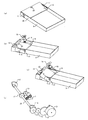
100の全体構成について説明する。図1(a)は、シート材給送制御機構を備えた画像形成装置100の概略断面図である。画像形成装置100は、電子写真プロセスを用いた、4色フルカラーのレーザプリンタである。画像形成装置100は、パーソナルコンピュータ(以下、PCという)等の外部ホスト装置から画像形成装置のコントローラである制御部50に入力される画像信号に基づいて、記録材であるシート材Sに画像を形成する。制御部50は、PC等の外部ホスト装置から画像信号等の印刷要求を受信すると、画像形成部、定着装置、給送制御部等に画像形成動作の開始を指示する。また、制御部50はROM、RAMを有しており、ROMには、制御部50が実行する制御プログラムやデータが格納されており、RAMは、制御部50が実行する制御プログラムが一時的に情報を保存するために使用されるメモリである。また、制御部50は時間測定を行うタイマ機能を有している。
[Entire configuration of image forming apparatus]
Referring to FIG. 1A, a color image forming apparatus according to a first embodiment (hereinafter referred to as an image forming apparatus).
The overall configuration of 100 will be described. FIG. 1A is a schematic cross-sectional view of an image forming apparatus 100 including a sheet material feeding control mechanism. The image forming apparatus 100 is a four-color full-color laser printer using an electrophotographic process. The image forming apparatus 100 prints an image on a sheet material S that is a recording material based on an image signal input from an external host device such as a personal computer (hereinafter referred to as a PC) to a control unit 50 that is a controller of the image forming apparatus. Form. When receiving a print request such as an image signal from an external host device such as a PC, the control unit 50 instructs the image forming unit, the fixing device, the feeding control unit, and the like to start an image forming operation. The control unit 50 includes a ROM and a RAM. The ROM stores a control program and data executed by the control unit 50. The RAM temporarily stores a control program executed by the control unit 50. Memory used to store information. The control unit 50 has a timer function for measuring time.

画像形成装置100では、フルカラー画像をシート材Sに形成するため、次のような制御動作が実行される。まず、画像形成部である4つの各プロセスカートリッジ(以下、カートリッジという)PY、PM、PC、PKの感光ドラム1が、反時計回り方向(図中、矢印方向)に所定の制御速度で回転駆動される。カートリッジPYはイエロー、カートリッジPMはマゼンタ、カートリッジPCはシアン、カートリッジPKはブラックのトナーを備えている。中間転写体であるベルト4も、図中矢印で示す時計回り方向に、感光ドラム1の速度に対応した速度で回転駆動される。更に、感光ドラム1に静電潜像を形成するスキャナユニット5も駆動される。   In the image forming apparatus 100, in order to form a full-color image on the sheet material S, the following control operation is executed. First, the photosensitive drums 1 of four process cartridges (hereinafter referred to as cartridges) PY, PM, PC, and PK that are image forming units are driven to rotate at a predetermined control speed in the counterclockwise direction (the arrow direction in the figure). Is done. The cartridge PY includes yellow toner, the cartridge PM includes magenta, the cartridge PC includes cyan, and the cartridge PK includes black toner. The belt 4 as an intermediate transfer member is also rotationally driven at a speed corresponding to the speed of the photosensitive drum 1 in the clockwise direction indicated by an arrow in the drawing. Further, the scanner unit 5 that forms an electrostatic latent image on the photosensitive drum 1 is also driven.

各カートリッジPY、PM、PC、PKにおいて、所定の制御タイミングで、帯電ローラ2が感光ドラム1の表面を所定の極性・電位となるように一様に帯電する。続いて、スキャナユニット5は、各カートリッジPY、PM、PC、PKの感光ドラム1の表面を各色の画像信号に応じて変調されたレーザ光で走査露光する。これにより、各感光ドラム1の表面の、レーザ光で走査露光された領域には、画像信号に応じた静電潜像が形成される。そして、各感光ドラム1の表面に形成された静電潜像は、現像器3のトナーにより現像され、トナー像が形成される。上述した画像形成プロセス動作により、感光ドラム1にはトナー像が形成され、各カートリッジPY、PM、PC、PKのトナー像は感光ドラム1の速度に対応した速度で回転駆動されるベルト4上に重畳転写される。   In each cartridge PY, PM, PC, PK, the charging roller 2 uniformly charges the surface of the photosensitive drum 1 to have a predetermined polarity and potential at a predetermined control timing. Subsequently, the scanner unit 5 scans and exposes the surface of the photosensitive drum 1 of each cartridge PY, PM, PC, and PK with a laser beam modulated according to the image signal of each color. As a result, an electrostatic latent image corresponding to the image signal is formed on the surface of each photosensitive drum 1 that has been scanned and exposed with the laser beam. The electrostatic latent image formed on the surface of each photosensitive drum 1 is developed with the toner of the developing device 3 to form a toner image. By the image forming process operation described above, a toner image is formed on the photosensitive drum 1, and the toner images of the respective cartridges PY, PM, PC, and PK are rotated on the belt 4 that is rotationally driven at a speed corresponding to the speed of the photosensitive drum 1. Superimposed transfer.

一方、シート材Sの搬送を行うシート材給送装置10においては、所定の制御タイミングで、給紙カセット9の後述する昇降板16に載置されたシート材Sに当接してシート材Sを給送する給送手段である給紙ローラ6と搬送ローラ7が駆動される。給紙カセット9上に積載されている記録媒体であるシート材Sは、給紙ローラ6により給送され、搬送ローラ7と分離ローラ8により1枚ずつ分離されて搬送路へ給送される。シート材Sの到達を検知する検知手段であるレジストセンサ101が、レジストローラ対11を通過して、搬送路上を搬送されるシート材Sの先端を検知すると、その旨を制御部50に通知する。そして、このとき、ベルト4上に転写されたトナー像と搬送ローラ7により搬送されたシート材Sが二次転写ニップ部に到達するタイミングが合うように、レジストローラ対11によるシート材Sの搬送速度の調整が行われる。   On the other hand, in the sheet material feeding device 10 that conveys the sheet material S, the sheet material S is brought into contact with a sheet material S placed on a lifting plate 16 (to be described later) of the sheet feeding cassette 9 at a predetermined control timing. The paper feed roller 6 and the transport roller 7 which are feeding means for feeding are driven. The sheet material S, which is a recording medium loaded on the paper feed cassette 9, is fed by the paper feed roller 6, separated one by one by the transport roller 7 and the separation roller 8, and fed to the transport path. When the registration sensor 101 serving as detection means for detecting the arrival of the sheet material S passes through the registration roller pair 11 and detects the leading edge of the sheet material S conveyed on the conveyance path, it notifies the control unit 50 of that fact. . At this time, the sheet material S is conveyed by the resist roller pair 11 so that the toner image transferred onto the belt 4 and the sheet material S conveyed by the conveying roller 7 reach the secondary transfer nip portion. The speed is adjusted.

その後、シート材Sが二次転写ローラ12とベルト4とのニップ部である二次転写ニップ部を挟持搬送されると、ベルト4上に形成された4色重畳のトナー像はシート材Sに転写される。続いて、シート材Sはベルト4の面から分離されて定着装置13へと搬送され、定着装置13の定着ニップ部にて加熱・加圧され、シート材S上の各色トナー像の混色及びシート材Sへの定着が行われる。そして、シート材Sは排紙ローラ対14により排紙トレイ15上に排出される。また、給紙カセット9上に積載されたシート材Sの枚数が少量になったときに、複数枚のシート材Sが重なって給送されないように、後述する昇降板16には分離パット20が設けられている。   Thereafter, when the sheet material S is nipped and conveyed through the secondary transfer nip portion, which is the nip portion between the secondary transfer roller 12 and the belt 4, the four-color superimposed toner image formed on the belt 4 is transferred to the sheet material S. Transcribed. Subsequently, the sheet material S is separated from the surface of the belt 4, conveyed to the fixing device 13, heated and pressed at the fixing nip portion of the fixing device 13, and the color mixture of each color toner image on the sheet material S and the sheet. Fixing to the material S is performed. Then, the sheet material S is discharged onto the paper discharge tray 15 by the paper discharge roller pair 14. In addition, when the number of sheet materials S stacked on the sheet feeding cassette 9 becomes small, a separation pad 20 is provided on the elevating plate 16 described later so that the plurality of sheet materials S are not overlapped and fed. Is provided.

[シート材給送装置の概要]
次に、シート材給送装置10の構成について説明する。図1(b)は、シート材給送装置の概略斜視図である。シート材給送装置10は、シート材Sを積載するための給紙カセット9、昇降板16を昇降させるための昇降機構、駆動源であるステッピングモータ21から給紙ローラ6、搬送ローラ7までの回転駆動の伝達経路から構成されている。本実施例のシート材給送装置10は、昇降板16に載置されたシート材Sの有無を検知するセンサ機能や、給紙カセット9に載置されたシート材の種類を判別するセンサ機能等のシート材検知手段は備えていない。なお、図1(b)に付した符号についての説明は後述する。
[Outline of sheet material feeding device]
Next, the configuration of the sheet material feeding device 10 will be described. FIG. 1B is a schematic perspective view of the sheet material feeding device. The sheet material feeding device 10 includes a sheet feeding cassette 9 for stacking the sheet material S, a lifting mechanism for lifting and lowering the lifting plate 16, a stepping motor 21 as a driving source, a sheet feeding roller 6, and a conveying roller 7. It is composed of a rotational drive transmission path. The sheet material feeding apparatus 10 according to the present exemplary embodiment has a sensor function that detects the presence or absence of the sheet material S placed on the lifting plate 16 and a sensor function that determines the type of the sheet material placed on the sheet feeding cassette 9. The sheet material detecting means such as is not provided. In addition, the description about the code | symbol attached | subjected to FIG.1 (b) is mentioned later.

[給紙カセット]
まず、図2を用いて、給紙カセット9について説明する。図2(a)は、給紙カセット9の概略斜視図である。給紙カセット9は、図1(a)に示す画像形成装置100の図中右側面である画像形成装置100の前面側から着脱自在となっており、ユーザによるシート材Sの載置及びジャム処理が容易に行えるように構成されている。図2(a)に示すように、給紙カセット9には、シート材Sが載置され、後述する上昇動作を行うことで、シート材Sを給紙ローラ6に付勢する昇降板16が設けられている。昇降板16は、昇降板の回転中心36を回転の中心として回転自在に位置決めされる。また、昇降板16の両端には、昇降板16の昇降動作を制御する昇降レバー18との係合部17が設けられている。
[Paper cassette]
First, the paper feed cassette 9 will be described with reference to FIG. FIG. 2A is a schematic perspective view of the paper feed cassette 9. The paper feed cassette 9 is detachable from the front side of the image forming apparatus 100, which is the right side of the image forming apparatus 100 shown in FIG. 1A, and the user places the sheet material S and performs jam processing. Is configured to be easily performed. As shown in FIG. 2A, the sheet material S is placed on the sheet feeding cassette 9, and an elevating plate 16 that biases the sheet material S toward the sheet feeding roller 6 by performing a lifting operation described later. Is provided. The elevating plate 16 is positioned so as to be rotatable about the rotation center 36 of the elevating plate. Further, at both ends of the lift plate 16, engagement portions 17 with lift levers 18 that control the lift operation of the lift plate 16 are provided.

[昇降板の昇降機構]
続いて、昇降板16の昇降機構について説明する。図2(b)は、昇降板16が不図示の給紙ローラ6から最も離間した状態(最も降下した状態)を示す概略斜視図、図2(c)は、昇降板16が上昇し、不図示の給紙ローラ6に当接した状態(最も上昇した状態)を示す概略斜視図である。画像形成装置100の本体側には、図2(b)、(c)に示すように、昇降レバー18が、昇降レバーの回転中心37を回転の中心として回転自在に位置決めされている。昇降レバー18は、不図示の付勢部材により給紙ローラ6の方向に付勢されている。画像形成装置100に給紙カセット9が装着された状態においては、前述した昇降板16の係合部17と昇降レバー18が係合し、昇降レバー18の昇降動作と連動して、昇降板16も昇降可能なように構成されている。
[Elevating mechanism of lifting plate]
Next, the lifting mechanism of the lifting plate 16 will be described. FIG. 2B is a schematic perspective view showing a state in which the elevating plate 16 is farthest from the paper feed roller 6 (not shown) (the most lowered state), and FIG. FIG. 6 is a schematic perspective view showing a state in which the paper feed roller 6 is in contact (the state in which it is raised most). On the main body side of the image forming apparatus 100, as shown in FIGS. 2B and 2C, the elevating lever 18 is positioned so as to be rotatable around the rotation center 37 of the elevating lever. The elevating lever 18 is urged in the direction of the paper feed roller 6 by an urging member (not shown). In the state in which the paper feed cassette 9 is mounted on the image forming apparatus 100, the engaging portion 17 of the elevating plate 16 and the elevating lever 18 are engaged, and the elevating plate 16 is interlocked with the elevating operation of the elevating lever 18. Is also configured to be movable up and down.

また、給紙ローラ6の方向に付勢された昇降レバー18の上昇動作は、昇降レバー18の上部に設けられた、昇降手段である昇降板昇降制御カム19(以下、制御カム19という)により規制される。図2(b)、(c)に示すように、制御カム19が回転することで、昇降レバー18が昇降し、昇降レバーとの係合部17を介して昇降板16が昇降する構成となっている。すなわち、図2(b)に示す昇降板16が下がりきった状態から制御カム19が図中、矢印方向に回転することにより、昇降板16は不図示の付勢部材により給紙ローラ6の方向に付勢され、制御カム19の形状に沿って上昇し、図2(c)に示す位置に移動する。更に、制御カム19を回転させることにより、昇降レバー18が制御カム19により図中、下方向に抑え込まれることにより、昇降板16は給紙ローラ6から離間する方向に移動し、図2(b)に示す状態に戻る。   Further, the lifting operation of the lifting lever 18 biased in the direction of the paper feed roller 6 is performed by a lifting plate lifting control cam 19 (hereinafter referred to as a control cam 19), which is a lifting means provided at the upper portion of the lifting lever 18. Be regulated. As shown in FIGS. 2B and 2C, when the control cam 19 is rotated, the elevating lever 18 is raised and lowered, and the elevating plate 16 is raised and lowered via the engaging portion 17 with the elevating lever. ing. That is, when the control cam 19 rotates in the direction of the arrow in the drawing from the state in which the elevating plate 16 is lowered as shown in FIG. 2B, the elevating plate 16 is moved in the direction of the paper feed roller 6 by an urging member not shown. Is moved along the shape of the control cam 19 and moved to the position shown in FIG. Further, when the control cam 19 is rotated, the lifting lever 18 is restrained downward by the control cam 19 in the drawing, so that the lifting plate 16 moves away from the paper feed roller 6, and FIG. Return to the state shown in b).

昇降板16の昇降動作は、シート材Sの1枚毎に繰り返され、昇降板16上に載置されたシート材Sは、給紙ローラ6に対して当接し付勢された位置と離間した位置との間を、制御カム19の回転動作により制御される。また、昇降板16上に設けられた分離パット20は、昇降板16に載置されたシート材Sが少なくなった際に、最上面に積載されたシート材Sの給紙ローラ6のピックアップ動作に引きずられて最下面のシート材Sが重送されないように設けられている。なお、分離パット20は、図2に示すように給紙ローラ6に対向する位置に設けられている。   The raising / lowering operation of the elevating plate 16 is repeated for each sheet material S, and the sheet material S placed on the elevating plate 16 is separated from the position where the sheet material S abuts against the paper feed roller 6 and is urged. The position is controlled by the rotation operation of the control cam 19. In addition, the separation pad 20 provided on the lifting plate 16 allows the sheet feeding roller 6 to pick up the sheet material S stacked on the uppermost surface when the sheet material S placed on the lifting plate 16 is reduced. The lowermost sheet material S is provided so as not to be double fed. The separation pad 20 is provided at a position facing the paper feed roller 6 as shown in FIG.

[駆動伝達経路]
次に、図2(d)を用いて、駆動源の回転が給紙ローラ6、搬送ローラ7へと伝達される駆動伝達経路について説明する。図2(d)は、本実施例における駆動伝達経路を示す概略斜視図である。画像形成装置100には、駆動源であるステッピングモータ21が備えられている。制御部50からの制御により、ステッピングモータ21は駆動され、ステッピングモータ21の回転駆動は、第1駆動ギア22から第2駆動ギア23へと伝達される。ここで、欠歯ギア24は不図示のソレノイドにより制御される欠歯ギアとなっており、第2駆動ギア23と選択的に噛み合う構成となっている。本実施例においては、欠歯ギア24と第2駆動ギア23の噛み合いをソレノイドにより制御する構成としているが、例えば電磁クラッチ等を用いて制御する構成でもよい。また、欠歯ギア24と制御カム19は同じ回転軸25に固定されており、一体となって回転するよう構成されている。すなわち、制御部50からの制御信号に基づいてソレノイドが動作すると、欠歯ギア24が第2駆動ギア23と噛み合い、ステッピングモータ21の駆動は欠歯ギア24を介して、同じ回転軸25に固定された制御カム19を回転させる構成となっている。
[Drive transmission path]
Next, a drive transmission path through which the rotation of the drive source is transmitted to the paper feed roller 6 and the transport roller 7 will be described with reference to FIG. FIG. 2D is a schematic perspective view showing a drive transmission path in the present embodiment. The image forming apparatus 100 includes a stepping motor 21 that is a drive source. The stepping motor 21 is driven by the control from the control unit 50, and the rotational drive of the stepping motor 21 is transmitted from the first drive gear 22 to the second drive gear 23. Here, the toothless gear 24 is a toothless gear controlled by a solenoid (not shown), and is configured to selectively mesh with the second drive gear 23. In the present embodiment, the meshing of the toothless gear 24 and the second drive gear 23 is controlled by a solenoid. However, a configuration in which the meshing is controlled using, for example, an electromagnetic clutch or the like may be used. The toothless gear 24 and the control cam 19 are fixed to the same rotation shaft 25 and are configured to rotate together. That is, when the solenoid operates based on the control signal from the control unit 50, the toothless gear 24 meshes with the second drive gear 23, and the driving of the stepping motor 21 is fixed to the same rotating shaft 25 via the toothless gear 24. The control cam 19 is rotated.

また、欠歯ギア24と制御カム19が固定された回転軸25にはギア27も固定されており、ギア27が回転すると、ギア27と噛み合わされたギア31も回転する。給紙ローラ6及び搬送ローラ7の端部には、ギア31と噛み合う歯面が形成されており、ギア31の回転を受けて、給紙ローラ6及び搬送ローラ7が回転駆動される。ここで、給紙ローラ6及び搬送ローラ7によるシート材Sの搬送距離は、欠歯ギア24と制御カム19の回転動作により、シート材Sを搬送路下流のレジストローラ対11へと搬送可能なように設定されている。   A gear 27 is also fixed to the rotary shaft 25 to which the toothless gear 24 and the control cam 19 are fixed. When the gear 27 rotates, the gear 31 engaged with the gear 27 also rotates. A tooth surface that meshes with the gear 31 is formed at the ends of the paper feed roller 6 and the transport roller 7, and the paper feed roller 6 and the transport roller 7 are rotationally driven by the rotation of the gear 31. Here, the conveyance distance of the sheet material S by the paper feed roller 6 and the conveyance roller 7 is such that the sheet material S can be conveyed to the registration roller pair 11 downstream of the conveyance path by the rotation operation of the missing gear 24 and the control cam 19. Is set to

このようにステッピングモータ21と制御カム19は連動しており、制御カム19が1回転することで、昇降板16の給紙ローラ6への当接、離間を行うことができる。従って、給紙ローラ6に昇降板16が付勢した位置でステッピングモータ21が脱調した場合には、ユーザがシート材Sを入れなおしても、昇降板16と給紙ローラ6は当接しているためにシート材Sの先端は昇降板16と給紙ローラ6の間に入らない。そのため、給紙ローラ6の正規の位置にシート材を載置することができない。   As described above, the stepping motor 21 and the control cam 19 are interlocked, and the control cam 19 makes one rotation so that the lifting plate 16 can be brought into contact with and separated from the paper feed roller 6. Therefore, when the stepping motor 21 steps out at the position where the lifting plate 16 is urged against the feeding roller 6, the lifting plate 16 and the feeding roller 6 are in contact with each other even if the user reinserts the sheet material S. Therefore, the leading edge of the sheet material S does not enter between the elevating plate 16 and the paper feed roller 6. Therefore, the sheet material cannot be placed at the normal position of the paper feed roller 6.

より詳細に説明すると、昇降レバー18は装置100の本体側に設けられているため、給紙カセット9を本体から取り出した場合、係合部17と昇降レバー18の係合が解除され、昇降板16は最も降下した状態となる。ゆえに、ユーザはシート材Sを昇降板16の上に置くことができる。しかし、この状態で給紙カセット9を再度本体に取り付ける場合、本体側の昇降レバー18は上がった状態のままなので、シート材Sの先端が昇降板16と給紙ローラ6の間に入る前に、昇降板16は上昇する。したがって、シート材Sの先端が給紙ローラ6に衝突してしまい、ユーザは給紙ローラ6の正規の位置にシート材Sを載置することができない。   More specifically, since the elevating lever 18 is provided on the main body side of the apparatus 100, when the paper feeding cassette 9 is taken out from the main body, the engagement between the engaging portion 17 and the elevating lever 18 is released, and the elevating plate 16 is in the most lowered state. Therefore, the user can place the sheet material S on the lifting plate 16. However, when the paper feed cassette 9 is attached to the main body again in this state, the lift lever 18 on the main body side remains in the raised state, so that before the leading edge of the sheet material S enters between the lift plate 16 and the paper feed roller 6. The elevating plate 16 is raised. Therefore, the leading edge of the sheet material S collides with the paper feed roller 6, and the user cannot place the sheet material S at the normal position of the paper feed roller 6.

[給送動作の制御シーケンス]
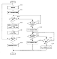
次に、図3のフローチャートを用いて、本実施例の給送動作について説明する。図3は、本実施例の給送動作の制御シーケンスを示すフローチャートであり、PC等の外部ホスト装置からの印刷要求を受信すると、制御部50により図3に示す処理が実行される。まず、ステップ101(以下、S101のように記す)では、制御部50は、画像形成部、定着装置、給送制御部等に、画像形成動作の開始を指示し、タイマをリセットし、スタートさせる。
[Control sequence of feeding operation]
Next, the feeding operation of this embodiment will be described using the flowchart of FIG. FIG. 3 is a flowchart showing a control sequence of the feeding operation of the present embodiment. When a print request is received from an external host device such as a PC, the processing shown in FIG. First, in step 101 (hereinafter referred to as S101), the control unit 50 instructs the image forming unit, the fixing device, the feeding control unit, etc. to start an image forming operation, resets and starts the timer. .

S102では、制御部50から画像形成動作の開示を指示されたステッピングモータ21は、給送動作の開始タイミングになると、加速回転を始め、欠歯ギア24を介して、欠
歯ギア24と同じ回転軸に固定された制御カム19を回転させる。前述したように、制御カム19が回転することで、昇降レバー18が上昇し、昇降レバー18との係合部17を介して昇降板16も上昇を始める。シート材Sを積載した昇降板16が、上昇動作を行うことにより、昇降板16の最上面のシート材Sと給紙ローラ6が当接する。また、制御カム19と同じ回転軸上のギア27により回転駆動されるギア31の回転を受け、給紙ローラ6と搬送ローラ7が回転駆動される。このようなシート材給送装置10の通常の給送動作を、以下では「第一の駆動動作」という。そして、給紙カセット9の昇降板16上に積載されている記録媒体であるシート材Sは、給紙ローラ6により給送され、搬送ローラ7と分離ローラ8により、1枚ずつ分離されて搬送路を給送される。
In step S <b> 102, the stepping motor 21 instructed to disclose the image forming operation from the control unit 50 starts accelerating rotation at the start timing of the feeding operation, and rotates the same as the missing gear 24 via the missing gear 24. The control cam 19 fixed to the shaft is rotated. As described above, when the control cam 19 rotates, the elevating lever 18 rises, and the elevating plate 16 starts to rise via the engaging portion 17 with the elevating lever 18. When the lifting plate 16 on which the sheet material S is stacked performs a lifting operation, the uppermost sheet material S of the lifting plate 16 and the paper feed roller 6 come into contact with each other. In addition, the feed roller 6 and the transport roller 7 are rotationally driven in response to the rotation of the gear 31 that is rotationally driven by the gear 27 on the same rotational axis as the control cam 19. Such a normal feeding operation of the sheet material feeding apparatus 10 is hereinafter referred to as a “first driving operation”. The sheet material S, which is a recording medium stacked on the lifting plate 16 of the paper feed cassette 9, is fed by the paper feed roller 6, and separated and transported one by one by the transport roller 7 and the separation roller 8. The road is fed.

S103では、制御部50は、レジストセンサ101からシート材Sを検知した通知を受信したかどうかにより、シート材Sが正常に搬送路を搬送されているかどうかを判断する。制御部50は、レジストセンサ101からシート材Sの先端を検知した通知を受信した場合には、シート材Sが正常に搬送路を搬送されていると判断し、S105に進み、受信していない場合には、S104に進む。S104では、制御部50は、タイマよりタイマ値を読み出し、シート材Sが給送開始されてからレジストセンサ101に到達するまでの時間である第一の所定時間が経過したかどうかを判断する。制御部50は、第一の所定時間が経過していないと判断した場合にはS103に戻り、第一の所定時間が経過したと判断した場合にはS109に進む。   In S <b> 103, the control unit 50 determines whether the sheet material S is normally conveyed on the conveyance path based on whether the notification that the sheet material S is detected is received from the registration sensor 101. When the control unit 50 receives the notification that the leading edge of the sheet material S is detected from the registration sensor 101, the control unit 50 determines that the sheet material S is normally conveyed on the conveyance path, proceeds to S105, and has not received it. In the case, the process proceeds to S104. In S <b> 104, the control unit 50 reads the timer value from the timer, and determines whether or not a first predetermined time, which is a time from when the sheet material S starts to be fed, to the registration sensor 101 has elapsed. When it is determined that the first predetermined time has not elapsed, the control unit 50 returns to S103, and when it is determined that the first predetermined time has elapsed, the control unit 50 proceeds to S109.

S105では、制御部50は、ベルト4上に転写されたトナー像と給送されたシート材Sへの転写位置を合わせるために、シート材Sを搬送するレジストローラ対11によるシート材Sの搬送速度調整を行う。そして、制御部50は、調整が完了すると、シート材Sにベルト4上のトナー像を転写するため、二次転写ニップ部へのシート材Sの搬送を行う。S106では、制御部50は、トナー像が転写されたシート材Sをベルト4から分離して定着装置13へ搬送させる。制御部50は、定着装置13の定着ニップ部でシート材Sを加熱・加圧し、トナー像をシート材に定着させる処理を行わせ、定着処理が終了したシート材Sを機外に排出する。   In S <b> 105, the control unit 50 conveys the sheet material S by the registration roller pair 11 that conveys the sheet material S in order to match the toner image transferred onto the belt 4 and the transfer position to the fed sheet material S. Adjust the speed. When the adjustment is completed, the controller 50 transfers the sheet material S to the secondary transfer nip portion in order to transfer the toner image on the belt 4 to the sheet material S. In S <b> 106, the control unit 50 separates the sheet material S to which the toner image has been transferred from the belt 4 and conveys the sheet material S to the fixing device 13. The control unit 50 heats and pressurizes the sheet material S at the fixing nip portion of the fixing device 13, causes the toner image to be fixed to the sheet material, and discharges the sheet material S after the fixing process to the outside.

S107では、制御部50は、全てのプリントが終了したかどうかを判断し、終了していなければS101に戻り、終了していれば、S108に進む。S108では、制御部50は、画像形成部、定着装置、給送制御部等に、画像形成動作の停止を指示し、処理を終了する。   In S107, the control unit 50 determines whether or not all printing has been completed, and if not completed, the process returns to S101, and if completed, the process proceeds to S108. In S108, the control unit 50 instructs the image forming unit, the fixing device, the feeding control unit, etc. to stop the image forming operation, and ends the processing.

S109以降の処理についての説明をする前に、給紙カセット9にシート材Sが載置されていない場合のステッピングモータ21の動作について述べる。給紙カセット9上にシート材Sが1枚もない場合は、昇降板16が上昇することにより、昇降板16に設けられた分離パット20が給紙ローラ6に当接し、付勢した状態(押圧した状態)になる。様々な紙種のシート材が昇降板16に載置されても、上側に載置されたシート材Sに最下面のシート材Sが引きずられないようにするため、分離パット20の摩擦係数は高く設定されている。そのため、分離パット20が給紙ローラ6に当接している状態でステッピングモータ21を回転させることは、給紙ローラ6の駆動源であるステッピングモータ21に過大な負荷をかけることになり、ステッピングモータ21が脱調する場合がある。本実施例において脱調とは、給紙ローラ6が停止したことによってステッピングモータ21が停止した場合のことを指す。すなわち、外部から過大な負荷をかけられたことによりステッピングモータ21が停止した場合のことを指す。また、ステッピングモータ21が脱調した場合、昇降板16は給紙ローラ6に対して付勢した状態で停止しているため、再び給紙を開始しても、再度、ステッピングモータ21は脱調してしまうことになる。   Before describing the processing after S109, the operation of the stepping motor 21 when the sheet material S is not placed on the sheet feeding cassette 9 will be described. When there is no sheet material S on the sheet feeding cassette 9, the elevating plate 16 is lifted so that the separation pad 20 provided on the elevating plate 16 comes into contact with the sheet feeding roller 6 and is urged ( Pressed state). In order to prevent the lowermost sheet material S from being dragged by the sheet material S placed on the upper side even when sheet materials of various paper types are placed on the lifting plate 16, the friction coefficient of the separation pad 20 is It is set high. Therefore, rotating the stepping motor 21 while the separation pad 20 is in contact with the paper feed roller 6 places an excessive load on the stepping motor 21 that is the drive source of the paper feed roller 6. 21 may step out. In the present embodiment, the step-out refers to the case where the stepping motor 21 is stopped due to the stop of the paper feed roller 6. That is, it indicates a case where the stepping motor 21 is stopped due to an excessive load applied from the outside. Further, when the stepping motor 21 steps out, the elevating plate 16 stops in a state where it is urged against the sheet feeding roller 6, and therefore the stepping motor 21 steps out again even when the sheet feeding is started again. Will end up.

そこで、S104において第一の所定時間が経過した場合、制御部50はステッピング
モータ21が脱調したと判断する。S109では、制御部50は、過負荷による脱調状態から復帰させるため、ステッピングモータ21を自起動領域の低速回転(第二の回転数)で所定時間だけ回転させる「第二の駆動動作」を行う。これにより、制御カム19を回転させ、昇降板16を給紙ローラ6から離間した位置まで移動させる。更に、制御部50は、第二の駆動動作を行う所定時間である第二の所定時間を測定するためにタイマをリセットし、スタートさせる。本実施例では、第二の所定時間は、制御カム19を回転させて、昇降板16を給紙ローラ6から最も離間した位置(図2(b))である正常位置まで戻すのに要する時間とする。S110では、制御部50は、タイマよりタイマ値を読み出し、第二の所定時間が経過したかどうか判断し、経過していればS111に進み、経過していなければS110の処理を繰り返す。S111では、制御部50は、シート材給送装置10による第二の駆動動作を停止させ、処理を終了する。
Therefore, when the first predetermined time has elapsed in S104, the control unit 50 determines that the stepping motor 21 has stepped out. In S109, the control unit 50 performs a “second drive operation” in which the stepping motor 21 is rotated at a low speed rotation (second rotation speed) in the self-activation region for a predetermined time in order to return from the step-out state due to overload. Do. As a result, the control cam 19 is rotated, and the elevating plate 16 is moved to a position separated from the paper feed roller 6. Furthermore, the control unit 50 resets and starts a timer to measure a second predetermined time which is a predetermined time for performing the second driving operation. In the present embodiment, the second predetermined time is the time required for rotating the control cam 19 to return the elevating plate 16 to the normal position which is the position farthest from the paper feed roller 6 (FIG. 2B). And In S110, the control unit 50 reads the timer value from the timer, determines whether or not the second predetermined time has elapsed, proceeds to S111 if it has elapsed, and repeats the processing of S110 if it has not elapsed. In S111, the control unit 50 stops the second driving operation by the sheet material feeding device 10 and ends the process.

[給送動作のタイムチャート]
上述したステッピングモータ21の駆動動作について、タイムチャートを用いて詳細に説明する。図4は、図3のフローチャートをタイムチャートで表した図であり、図4(a)は、シート材Sが給紙カセット9に載置されている場合、図4(b)は、シート材Sが給紙カセット9に載置されていない場合のタイムチャートである。図4(a)、(b)において、縦軸はステッピングモータ21のモータ回転数(単位:rad/s(ラジアン/秒))、横軸は時間(単位:s(秒))を示す。また、図中のTから始まる符号(例えばT101等)は時間タイミングを示し、符号中の番号は、図3で説明したフローチャート中の各処理に付したSで始まるステップ番号に対応する。
[Time chart of feeding operation]
The driving operation of the above stepping motor 21 will be described in detail using a time chart. FIG. 4 is a time chart of the flowchart of FIG. 3. FIG. 4A shows a case where the sheet material S is placed on the paper feed cassette 9, and FIG. 6 is a time chart when S is not placed in the paper feed cassette 9; 4A and 4B, the vertical axis represents the motor rotation speed (unit: rad / s (radian / second)) of the stepping motor 21, and the horizontal axis represents time (unit: s (second)). Also, a code starting from T (for example, T101) in the figure indicates a time timing, and the number in the code corresponds to a step number starting with S attached to each process in the flowchart described in FIG.

図4(a)において、時間タイミングT101(以下、単にT101と記載する)で給紙が開始(図3のS101)されると、ステッピングモータ21の回転数を上昇させる。そして、T102で給送動作の開始タイミング(シート材Sのピックアップのタイミング)になると、第一の駆動動作を実施する(図3のS102)。これにより、ステッピングモータ21の回転速度を高速の領域(第一の回転数)で駆動し、シート材Sを給送させる。T103でレジストセンサ101がシート材Sの先端を検知すると(図3のS103 YES)、シート材Sを搬送するレジストローラ対11によるシート材Sの搬送速度調整が行われる(図3のS105)。そして、調整が完了すると、T105で二次転写ニップ部へのシート材Sの搬送を行う(図3のS105)。T106では、トナー像が転写されたシート材Sを定着装置13へ搬送し、トナー像をシート材に定着させる処理を行い、定着処理が終了したシート材Sは機外に排出される。そして、2枚目のシート材Sの給紙を開始する(図3のS101)。   In FIG. 4A, when sheet feeding is started at time timing T101 (hereinafter simply referred to as T101) (S101 in FIG. 3), the rotation speed of the stepping motor 21 is increased. At T102, when the feeding operation start timing (sheet material S pickup timing) is reached, the first driving operation is performed (S102 in FIG. 3). Thereby, the rotational speed of the stepping motor 21 is driven in a high speed region (first rotational speed), and the sheet material S is fed. When the registration sensor 101 detects the leading edge of the sheet material S at T103 (YES in S103 in FIG. 3), the conveyance speed of the sheet material S is adjusted by the registration roller pair 11 that conveys the sheet material S (S105 in FIG. 3). When the adjustment is completed, the sheet material S is conveyed to the secondary transfer nip portion at T105 (S105 in FIG. 3). At T106, the sheet material S to which the toner image has been transferred is conveyed to the fixing device 13, and the toner image is fixed to the sheet material. The sheet material S for which the fixing process has been completed is discharged out of the apparatus. Then, feeding of the second sheet material S is started (S101 in FIG. 3).

続いて、図4(b)のタイムチャートについて説明する。本実施例の画像形成装置100には、給紙カセット9にシート材有無センサが設けられていないので、給紙カセット9にシート材Sがない状態でも、図4(a)と同様に、T101で第一の駆動動作が行われる(図3のS101)。その結果、分離パット20と給紙ローラ6が当接し、ステッピングモータ21が過負荷状態となっても、ステッピングモータ21は高速度でそのまま動作することとなる。印刷(プリント)を開始してから1枚目の印刷であれば、図4(b)の給送動作の開始タイミング(T102)に示すようにステッピングモータ21の回転速度を加速している最中(シート材S無しのピックアップのタイミング)に過負荷状態となる。また、印刷開始してから2枚目以降のシート材Sへの印刷時にシート材がなくなった場合には、定着装置へ搬送(図4(a)のT106)した後の一定速度(第一の回転数)の状態で、次のシート材の給紙ローラ6によるピックアップ時に過負荷状態となる。モータの回転を加速している状態で、ステッピングモータ21が過負荷状態により脱調した場合は制御不能となり、給送動作が終了しても脱調状態から復帰しない。ユーザが再度印刷を試み、給送開始(図3のS101)を繰り返したとしても、分離パット20と給紙ローラ6が当接した状態では、再びステッピングモータ21が脱調する。更に、昇降板16が給
紙ローラ6に付勢(押圧)した位置で停止している状態では、ユーザが給紙カセット9にシート材Sを入れ直しても、シート材Sの搬送方向の先端が昇降板16と給紙ローラ6の間に入らずジャムとなってしまう。
Then, the time chart of FIG.4 (b) is demonstrated. In the image forming apparatus 100 of this embodiment, since the sheet material presence / absence sensor is not provided in the sheet feeding cassette 9, even in a state where the sheet material S does not exist in the sheet feeding cassette 9, as in FIG. Thus, the first driving operation is performed (S101 in FIG. 3). As a result, even when the separation pad 20 and the paper feed roller 6 come into contact with each other and the stepping motor 21 is overloaded, the stepping motor 21 operates as it is at a high speed. If it is the first printing after printing (printing) is started, the rotational speed of the stepping motor 21 is being accelerated as shown in the feeding operation start timing (T102) in FIG. 4B. An overload condition occurs at the timing of pickup without the sheet material S. In addition, when there is no sheet material at the time of printing on the second and subsequent sheet materials S from the start of printing, a constant speed (first time after transporting to the fixing device (T106 in FIG. 4A)). In the state of the number of rotations), an overload state occurs when the next sheet material is picked up by the sheet feeding roller 6. If the stepping motor 21 steps out due to an overload state while the motor is accelerating, control becomes impossible, and even if the feeding operation ends, the stepping motor 21 does not return from the step out state. Even if the user tries printing again and repeats the feeding start (S101 in FIG. 3), the stepping motor 21 steps out again when the separation pad 20 and the paper feed roller 6 are in contact with each other. Further, in a state where the elevating plate 16 is stopped at a position where it is urged (pressed) against the paper feed roller 6, even if the user reinserts the sheet material S into the paper feed cassette 9, the leading end of the sheet material S in the transport direction is The jam occurs between the lifting plate 16 and the paper feed roller 6.

そのため、図4(b)では、シート材SがないことによりT102にてステッピングモータ21が脱調する。その結果、シート材Sが搬送されないため、T101から第一の所定時間が経過したT103においてレジストセンサ101がシート材Sを未検知なので(タイムアウト)(図3のS104 YES)は、T109で第二の駆動動作を開始する(図3のS109)。前述したように、第二の駆動動作とは、ステッピングモータ21を自起動領域の低速回転(第二の回転数)で回転させることを指し、第二の回転数は、上述した第一の回転数よりも小さい回転数である。ここでステッピングモータの自起動領域とは、ステッピングモータの一般的な基本特性であり、ステッピングモータに外部から入力されるパルス信号に同期して起動可能なステッピングモータの初速度を意味する。そして、第二の駆動動作が行われる第二の所定時間が経過すると、T111で第二の駆動動作は停止され、昇降板16は、給紙ローラ6から最も離間した位置(図2(b))で停止した状態となる。   Therefore, in FIG. 4B, the absence of the sheet material S causes the stepping motor 21 to step out at T102. As a result, since the sheet material S is not conveyed, the registration sensor 101 does not detect the sheet material S at T103 after the first predetermined time has elapsed from T101 (timeout) (YES in S104 in FIG. 3). The driving operation is started (S109 in FIG. 3). As described above, the second driving operation refers to rotating the stepping motor 21 at a low speed rotation (second rotation speed) in the self-starting region, and the second rotation speed is the first rotation described above. The number of rotations is smaller than the number. Here, the self-starting region of the stepping motor is a general basic characteristic of the stepping motor, and means an initial speed of the stepping motor that can be started in synchronization with a pulse signal input from the outside to the stepping motor. Then, when a second predetermined time during which the second driving operation is performed elapses, the second driving operation is stopped at T111, and the elevating plate 16 is positioned farthest from the sheet feeding roller 6 (FIG. 2B). ) To stop.

ステッピングモータを自起動領域で駆動させることにより、脱調を起こしても、再度、外部から入力されるパルス信号に同期して回転起動されるため、分離パット20と給紙ローラ6が当接した過大な負荷が加わった状態から脱することができる。また、一般的に、モータの出力トルクは高速回転より低速回転の方が高いことから、自起動領域で低速回転させることにより、ステッピングモータ21の過負荷状態の原因である分離パット20と給紙ローラ6の当接状態から離間状態へ復帰させることができる。   By driving the stepping motor in the self-starting region, even if a step-out occurs, the separation pad 20 and the paper feed roller 6 come into contact with each other because the rotation is started again in synchronization with the pulse signal input from the outside. It is possible to escape from a state where an excessive load is applied. In general, the output torque of the motor is higher at low speed than at high speed. Therefore, by rotating at low speed in the self-starting region, the separation pad 20 and the paper feeding cause of the overload state of the stepping motor 21 are supplied. The contact state of the roller 6 can be returned to the separated state.

以上説明したように、本実施例によれば、低出力のステッピングモータを用いた装置において、昇降板が給送ローラに付勢した状態から正常な状態に復帰することができる。ユーザが給紙カセットにシート材を入れ忘れた場合においても、昇降板が給送ローラに付勢した状態で停止し、シート材を載置できなくなる状態を回避する。そして、給送動作に必要な低出力に抑えた安価なステッピングモータを搭載できるため、コストダウンを実現することができる。   As described above, according to the present embodiment, in the apparatus using the low output stepping motor, the state where the lifting plate is urged by the feeding roller can be returned to the normal state. Even when the user forgets to put the sheet material into the sheet feeding cassette, the lifting plate is stopped in a state where it is urged by the feeding roller, and the state where the sheet material cannot be placed is avoided. Since an inexpensive stepping motor with a low output required for the feeding operation can be mounted, the cost can be reduced.

また、本実施例においては、昇降板16に分離パット20が設けられている構成を前提としていた。しかし、分離パット20は必ずしも設けられている必要はない。本発明は給紙ローラ6が分離パット20と比較して摩擦係数の低い箇所に当接した場合にも、ステッピングモータ21が脱調してしまうような構成にも適用できる。   Further, in this embodiment, it is assumed that the separation pad 20 is provided on the lifting plate 16. However, the separation pad 20 is not necessarily provided. The present invention can also be applied to a configuration in which the stepping motor 21 steps out even when the paper feed roller 6 comes into contact with a portion having a lower friction coefficient than the separation pad 20.

また、本実施例においては、給紙カセット9にシート材Sが積載されていない場合の制御について説明したが、給紙カセット9からレジストセンサ101までの搬送路においてシート材Sが滞留した場合(ジャムという)にも適用できる。ジャムが起きた場合に昇降板16を降下させることによって、ユーザがジャム処理を行いやすくするという効果がある。   In this embodiment, the control when the sheet material S is not stacked on the sheet feeding cassette 9 has been described. However, when the sheet material S stays in the conveyance path from the sheet feeding cassette 9 to the registration sensor 101 ( It can also be applied to jams). When the jam occurs, the lifting plate 16 is lowered, so that the user can easily perform the jam processing.

また、本実施例においては、給紙ローラ6から最も離間させた状態まで昇降板16を降下させたが、脱調状態から抜け出し、シート材Sを1枚でも収容できる程度まで昇降板16を降下させる構成であってもよい。   Further, in this embodiment, the elevating plate 16 is lowered to the state where it is farthest from the paper feed roller 6. However, the elevating plate 16 is lowered to the extent that it can escape from the step-out state and can accommodate even one sheet material S. The structure to be made may be sufficient.

実施例1では、シート材が給紙カセットに載置されていない場合に、給紙ローラと分離パットの当接によりステッピングモータが脱調し、第二の駆動動作を所定時間駆動することにより、給紙ローラと分離パットを離間させる構成について説明した。実施例2では、
給紙カセット上に載置されたシート材の紙種と異なったシート材をユーザが印刷設定したことにより、ステッピングモータが脱調した場合の第二の駆動動作について説明する。なお、本実施例においても、実施例1の図1、図2で説明した画像形成装置100、シート材給送装置10を使用するものとし、実施例1と同じ構成については同一符号を付し、説明を省略する。
In the first embodiment, when the sheet material is not placed on the sheet feeding cassette, the stepping motor is stepped out by the contact between the sheet feeding roller and the separation pad, and the second driving operation is driven for a predetermined time. The configuration for separating the paper feed roller and the separation pad has been described. In Example 2,
A second driving operation in the case where the stepping motor has stepped out due to the user setting to print a sheet material different from the paper type of the sheet material placed on the paper feed cassette will be described. Also in this embodiment, the image forming apparatus 100 and the sheet material feeding apparatus 10 described in FIGS. 1 and 2 of the first embodiment are used, and the same components as those in the first embodiment are denoted by the same reference numerals. The description is omitted.

[給送動作の制御シーケンス]
まず、本実施例の給送動作について、図5のフローチャートを用いて説明する。図5は、本実施例の給送動作の制御シーケンスを示すフローチャートであり、PC等の外部ホスト装置からの印刷要求を受信すると、制御部50により図5に示す処理が実行される。なお、図5において、実施例1の図3に示す処理と同一の処理については、同じステップ番号を付している。
[Control sequence of feeding operation]
First, the feeding operation of this embodiment will be described with reference to the flowchart of FIG. FIG. 5 is a flowchart showing a control sequence of the feeding operation of this embodiment. When a print request is received from an external host device such as a PC, the processing shown in FIG. In FIG. 5, the same step numbers are assigned to the same processes as those shown in FIG. 3 of the first embodiment.

図5において、シート材Sが正常に搬送され、プリントが行われる場合の処理であるS101〜S108については、実施例1の図3において説明した処理が行われるので、ここでの説明を省略する。本実施例では、給紙カセット上に載置されたシート材Sの紙種と異なった紙種のシート材をユーザが印刷設定した場合の第二の駆動動作について説明する。例えば、厚紙など特定の紙種のシート材は、後述する図6(a)に示すように、定着装置13における各色のトナー像の定着性能を高めるため、定着動作と給送動作を低速で行う必要がある。この場合、シート材Sは搬送ローラ7の周囲で湾曲されながら、レジストローラ対11までの搬送路上を、通常時に比べて搬送速度を落とし、低速で給送される。しかしながら、ユーザが通常のシート材として給紙カセット9に載置されたシート材の設定を行った場合は、給紙カセット9に載置された厚紙などのシート材が、速い搬送速度で給送されてしまう。そのため、厚紙など材質が固いシート材が給紙ローラ6などに過大な負荷を加えることにより、給紙ローラ6の駆動源であるステッピングモータ21に過大な負荷がかかる状態となり、ステッピングモータ21は脱調を引き起こしてしまう。ステッピングモータ21が過大な負荷により脱調しているので、シート材Sは搬送路上に留まった状態で搬送されず、給送開始から第一の所定時間が経過しても、レジストセンサ101がシート材Sの先端を検知することはない(S104 YES)。   In FIG. 5, the processing described in FIG. 3 of the first embodiment is performed for S <b> 101 to S <b> 108, which are processing when the sheet material S is normally conveyed and printed, and thus description thereof is omitted here. . In the present embodiment, a second driving operation in the case where the user prints a sheet material of a paper type different from the paper type of the sheet material S placed on the paper feed cassette will be described. For example, a sheet material of a specific paper type such as thick paper performs a fixing operation and a feeding operation at a low speed in order to improve the fixing performance of each color toner image in the fixing device 13, as shown in FIG. There is a need. In this case, while the sheet material S is curved around the conveyance roller 7, the sheet material S is fed at a low speed on the conveyance path to the registration roller pair 11 at a lower conveyance speed than normal. However, when the user sets the sheet material placed on the paper feed cassette 9 as a normal sheet material, the sheet material such as cardboard placed on the paper feed cassette 9 is fed at a high conveyance speed. It will be. Therefore, an excessive load is applied to the stepping motor 21 that is a driving source of the sheet feeding roller 6 by applying an excessive load to the sheet feeding roller 6 or the like with a hard sheet material such as thick paper, and the stepping motor 21 is removed. Cause a tone. Since the stepping motor 21 has stepped out due to an excessive load, the sheet material S is not conveyed while remaining on the conveying path, and even if the first predetermined time has elapsed from the start of feeding, the registration sensor 101 does not move. The tip of the material S is not detected (S104 YES).

そこで、S120では、制御部50は、実施例1と同様に、ステッピングモータ21を自起動領域の低速回転で所定時間だけ回転させる第二の駆動動作を行う。更に、制御部50は、第二の駆動動作を行う所定時間である第二の所定時間を測定するためにタイマをリセットし、スタートさせる。S121では、制御部50は、タイマよりタイマ値を読み出し、第二の所定時間が経過したかどうか判断し、経過していればS122に進み、経過していなければS123に進む。S122では、制御部50は、シート材給送装置10による第二の駆動動作を停止させ、処理を終了する。このとき、昇降板16は、実施例1と同様に、給紙ローラ6から最も離間した位置(図2(b))で停止した状態となる。   Therefore, in S120, the control unit 50 performs a second drive operation for rotating the stepping motor 21 for a predetermined time at a low speed rotation in the self-starting region, as in the first embodiment. Furthermore, the control unit 50 resets and starts a timer to measure a second predetermined time which is a predetermined time for performing the second driving operation. In S121, the control unit 50 reads the timer value from the timer, determines whether or not the second predetermined time has elapsed, proceeds to S122 if it has elapsed, and proceeds to S123 if it has not elapsed. In S122, the control unit 50 stops the second driving operation by the sheet material feeding apparatus 10 and ends the process. At this time, the lift plate 16 is stopped at a position farthest from the paper feed roller 6 (FIG. 2B), as in the first embodiment.

S123では、制御部50は、レジストセンサ101からシート材Sを検知した通知を受信したかどうかにより、ステッピングモータ21が脱調状態から脱し、シート材Sが正常に搬送路を搬送されているかどうかを判断する。すなわち、本実施例では、シート材Sの紙種に応じた搬送速度でシート材給送装置10による給送処理が行われていないため、ステッピングモータ21の脱調により、シート材Sは搬送路上で停止した状態となっている。ところが、本実施例では、第二の駆動動作により、ステッピングモータ21が低速回転で駆動されることにより脱調状態を脱し、給紙ローラ6、搬送ローラ7が駆動されることにより、シート材Sの搬送が再開される。その結果、シート材Sが搬送路上を搬送され、シート材Sがレジストローラ対11を通過して、レジストセンサ101によりシート材Sの先端が検知される状態となる。制御部50は、レジストセンサ101からシート材Sの先端を検知した通知を受信していなければS121の処理に戻り、通知を受信していた
場合には、ステッピングモータ21が脱調状態から復帰し、シート材Sが正常に搬送されたと判断し、S124に進む。
In S123, the control unit 50 determines whether or not the stepping motor 21 has come out of the step-out state depending on whether or not the notification that the sheet material S is detected is received from the registration sensor 101, and whether or not the sheet material S is normally conveyed on the conveyance path. Judging. In other words, in the present embodiment, the sheet material feeding apparatus 10 does not perform the feeding process at the conveyance speed corresponding to the paper type of the sheet material S. It is in a stopped state. However, in the present embodiment, the stepping motor 21 is driven at a low speed rotation by the second driving operation, so that the step-out state is released, and the sheet feeding roller 6 and the conveying roller 7 are driven, whereby the sheet material S is driven. Is resumed. As a result, the sheet material S is conveyed on the conveyance path, the sheet material S passes through the registration roller pair 11, and the leading edge of the sheet material S is detected by the registration sensor 101. The control unit 50 returns to the process of S121 if it has not received the notification of detecting the leading edge of the sheet material S from the registration sensor 101, and if it has received the notification, the stepping motor 21 returns from the step-out state. Then, it is determined that the sheet material S has been normally conveyed, and the process proceeds to S124.

S124では、制御部50は、シート材給送装置10による第二の駆動動作を停止させ、処理を終了する。この時点では、第二の所定時間が経過していないため、昇降板16は、給紙ローラ6がシート材Sに当接した位置から離間している途中(下降している途中)で第二の駆動動作を停止させることとなる。従って、実施例1で記載した制御カム19を第二の所定時間だけ回転させ続けて1回転させ、昇降板16を給紙ローラ6から最も離間した位置(図2(b))となる位置に戻す制御とは異なる。給紙ローラ6に対して、十分に離間した位置まで昇降板16を昇降させていないため、ユーザが給紙カセット9にシート材を満載させることができない場合がある。しかしながら、第二の駆動動作の途中ではあるが、レジストセンサ101によりシート材Sが検知されたタイミングでステッピングモータ21の動作を停止させることで、シート材Sがレジストセンサ101よりも搬送路下流に搬送される事態を回避できる。S120において、第二の駆動動作が開始されると、画像形成に関する定着装置13などの駆動は停止している。この場合、シート材Sがレジストセンサ101よりも搬送路の下流側に搬送されると、定着装置13の付近で滞留し、ジャム処理が困難になる。ゆえに、シート材Sがレジストセンサ101よりも搬送路の下流側に搬送される事態は回避することが望ましい。以上より、シート材Sはレジストセンサ101付近で停止しているため、ユーザによるジャム処理の作業を、搬送路下流で行う場合に比較して容易に行うことができる。   In S124, the control unit 50 stops the second driving operation by the sheet material feeding apparatus 10, and ends the process. At this time, since the second predetermined time has not elapsed, the lifting plate 16 is in the middle of being separated from the position where the paper feeding roller 6 is in contact with the sheet material S (while it is being lowered). The driving operation is stopped. Therefore, the control cam 19 described in the first embodiment is continuously rotated for the second predetermined time to make one rotation, and the elevating plate 16 is located at the position farthest from the paper feed roller 6 (FIG. 2B). This is different from the return control. Since the elevating plate 16 is not lifted or lowered to a position sufficiently separated from the paper feed roller 6, the user may not be able to fully load the sheet material into the paper feed cassette 9. However, although in the middle of the second driving operation, the operation of the stepping motor 21 is stopped at the timing when the sheet material S is detected by the registration sensor 101, so that the sheet material S is located downstream of the conveyance path from the registration sensor 101. The situation where it is conveyed can be avoided. In S120, when the second driving operation is started, driving of the fixing device 13 and the like related to image formation is stopped. In this case, when the sheet material S is conveyed downstream of the registration sensor 101 in the conveyance path, the sheet material S stays in the vicinity of the fixing device 13 and jamming processing becomes difficult. Therefore, it is desirable to avoid a situation in which the sheet material S is conveyed downstream of the registration sensor 101 in the conveyance path. As described above, since the sheet material S is stopped in the vicinity of the registration sensor 101, it is possible to easily perform the jam processing operation by the user as compared with the case where the operation is performed downstream of the conveyance path.

[給送動作のタイムチャート]
上述したステッピングモータ21の駆動動作について、タイムチャートを用いて説明する。図6は、図5のフローチャートをタイムチャートで表した図である。図6(a)は、正しい紙種のシート材Sが給紙カセット9に載置されている場合、図6(b)は、指定されたシート材の紙種と異なる紙種のシート材Sが給紙カセット9に載置されている場合のタイムチャートである。図6(a)、(b)において、縦軸はステッピングモータ21のモータ回転数(単位:rad/s(ラジアン/秒))、横軸は時間(単位:s(秒))を示す。図6(a)では、通常のシート材の場合のステッピングモータ21の回転数を破線で示し、厚紙等の特定のシート材の場合の回転数を実線で示している。図6(a)に示すように、シート材Sが厚紙の場合には、通常のシート材に比べて、ステッピングモータ21の回転数を抑えて、遅い搬送速度で搬送動作が行われることがわかる。なお、図中のTから始まる符号(例えばT101等)は時間タイミングを示し、符号中の番号は、図5で説明したフローチャート中の各処理に付したSで始まるステップ番号に対応する。図6(a)のタイムチャートは、シート材Sが厚紙であるため、ステッピングモータの回転数が実施例1よりも遅いことを除けば、実施例1で説明した図4(a)に示すタイムチャートと同様であり、説明を省略する。
[Time chart of feeding operation]
The driving operation of the above stepping motor 21 will be described using a time chart. FIG. 6 is a time chart of the flowchart of FIG. 6A shows a case where a sheet material S of the correct paper type is placed in the paper feed cassette 9, and FIG. 6B shows a sheet material S of a paper type different from the paper type of the designated sheet material. Is a time chart when the paper is placed in the paper feed cassette 9. 6A and 6B, the vertical axis represents the motor rotation speed (unit: rad / s (radian / second)) of the stepping motor 21, and the horizontal axis represents time (unit: s (second)). In FIG. 6A, the rotation speed of the stepping motor 21 in the case of a normal sheet material is indicated by a broken line, and the rotation speed in the case of a specific sheet material such as cardboard is indicated by a solid line. As shown in FIG. 6A, when the sheet material S is thick paper, it is understood that the conveyance operation is performed at a low conveyance speed while suppressing the number of rotations of the stepping motor 21 as compared with a normal sheet material. . In the figure, a code beginning with T (for example, T101) indicates a time timing, and the number in the code corresponds to a step number starting with S attached to each process in the flowchart described in FIG. The time chart of FIG. 6A shows the time shown in FIG. 4A described in the first embodiment except that the sheet material S is thick paper and the rotation speed of the stepping motor is slower than that of the first embodiment. This is the same as the chart, and the description is omitted.

続いて、図6(b)のタイムチャートについて説明する。図6(a)と同様に、T101で第一の駆動動作が行われ(図5のS101)、ステッピングモータ21は高速度で動作することとなる。印刷(プリント)を開始してから1枚目の印刷であれば、図6(b)の給送動作の開始タイミング(T102)に示すように、給送動作を開始してしばらくはシート材Sの搬送が行われる。ところが、給紙カセット9に載置されたシート材Sは、指定された普通紙とは異なる紙種の厚紙であるため、給紙ローラ6、搬送ローラ7に過大な負荷がかかる。その結果、ステッピングモータ21は所定の回転速度である高速で駆動されている最中に過負荷状態となり、脱調状態となる。そのため、シート材Sは搬送路上に停止した状態となる。その結果、T101から第一の所定時間が経過したT103においてレジストセンサ101がシート材Sを検知しないので(図5のS104 YES)、T120において第二の駆動動作が開始される(図5のS120)。   Next, the time chart of FIG. 6B will be described. As in FIG. 6A, the first drive operation is performed at T101 (S101 in FIG. 5), and the stepping motor 21 operates at a high speed. If it is the first printing after the start of printing (printing), as shown in the start timing (T102) of the feeding operation in FIG. Is carried out. However, since the sheet material S placed in the paper feed cassette 9 is a thick paper of a paper type different from the designated plain paper, an excessive load is applied to the paper feed roller 6 and the transport roller 7. As a result, the stepping motor 21 is overloaded while being driven at a high speed, which is a predetermined rotation speed, and is in a step-out state. Therefore, the sheet material S is stopped on the conveyance path. As a result, since the registration sensor 101 does not detect the sheet material S at T103 after the first predetermined time has elapsed from T101 (YES in S104 in FIG. 5), the second driving operation is started at T120 (S120 in FIG. 5). ).

第二の駆動動作により、ステッピングモータ21が低速回転で駆動されることにより脱調状態を脱し、給紙ローラ6、搬送ローラ7が駆動されることにより、シート材Sの搬送が再開される。その結果、シート材Sが搬送路上を搬送され、シート材Sがレジストローラ対11を通過して、レジストセンサ101によりシート材Sの先端が検知される状態となる(図5のS123 YES)。シート材Sが検知されたT124では、シート材給送装置10による第二の駆動動作が停止される(図5のS124)。   By the second driving operation, the stepping motor 21 is driven at a low speed rotation to escape the step-out state, and the sheet feeding roller 6 and the conveying roller 7 are driven, whereby the conveyance of the sheet material S is resumed. As a result, the sheet material S is conveyed on the conveyance path, the sheet material S passes through the registration roller pair 11, and the registration sensor 101 detects the leading edge of the sheet material S (YES in S123 in FIG. 5). At T124 when the sheet material S is detected, the second driving operation by the sheet material feeding apparatus 10 is stopped (S124 in FIG. 5).

一方、実施例1と同様に給紙カセットにシート材Sが載置されていない場合には、第二の駆動動作に要する所定時間が経過したときに(図5のS121 YES)、T122にてシート材給送装置10による第二の駆動動作を停止させる(図5のS122)。このとき、昇降板16は、実施例1と同様に、給紙ローラ6から最も離間した位置(図2(b))となる。   On the other hand, when the sheet material S is not placed in the paper feed cassette as in the first embodiment, when a predetermined time required for the second driving operation has elapsed (YES in S121 in FIG. 5), at T122. The second driving operation by the sheet material feeding apparatus 10 is stopped (S122 in FIG. 5). At this time, as in the first embodiment, the elevating plate 16 is positioned farthest from the paper feed roller 6 (FIG. 2B).

本実施例では、レジストセンサ101がシート材Sを検知したタイミングで、ステッピングモータ21の動作を停止している。しかしながら、給紙ローラ6に対する昇降板16の離間タイミングと、レジストセンサ101がシート材Sを検知するタイミングの前後関係は、制御カム19の形状やレジストセンサ101の設置位置や給送経路により異なる。従って、レジストセンサ101がシート材Sを検知したタイミングに応じて第二の駆動動作を停止させる時間は適宜変更してもよい。以上説明したように、本実施例によれば、低出力のステッピングモータを用いた装置において、昇降板が給送ローラに付勢した状態から正常な状態に復帰することができる。   In this embodiment, at the timing when the registration sensor 101 detects the sheet material S, the operation of the stepping motor 21 is stopped. However, the anteroposterior relationship between the separation timing of the lifting plate 16 with respect to the paper feed roller 6 and the timing at which the registration sensor 101 detects the sheet material S differs depending on the shape of the control cam 19, the installation position of the registration sensor 101, and the feeding path. Therefore, the time for stopping the second driving operation may be changed as appropriate in accordance with the timing at which the registration sensor 101 detects the sheet material S. As described above, according to the present embodiment, in the apparatus using the low output stepping motor, the state where the lifting plate is urged by the feeding roller can be returned to the normal state.

実施例1、2のステッピングモータの第二の駆動動作では、ステッピングモータの回転制御は、自起動領域の低速回転としていた。実施例3では、ステッピングモータを駆動する電流値を増加させることにより、第二の駆動動作におけるステッピングモータを、一時的に高い出力で制御する実施の形態について説明する。なお、本実施例においても、実施例1の図1、図2で説明した画像形成装置100、シート材給送装置10を使用するものとし、実施例1と同じ構成については同一符号を付し、説明を省略する。   In the second driving operation of the stepping motors of the first and second embodiments, the rotation control of the stepping motor is a low-speed rotation in the self-starting area. In Example 3, an embodiment will be described in which the stepping motor in the second driving operation is temporarily controlled at a high output by increasing the current value for driving the stepping motor. Also in this embodiment, the image forming apparatus 100 and the sheet material feeding apparatus 10 described in FIGS. 1 and 2 of the first embodiment are used, and the same components as those in the first embodiment are denoted by the same reference numerals. The description is omitted.

[給送動作の制御シーケンス]
本実施例の給送動作について、図7のフローチャートを用いて説明する。図7は、本実施例の給送動作の制御シーケンスを示すフローチャートであり、PC等の外部ホスト装置からの印刷要求を受信すると、制御部50により図7に示す処理が実行される。なお、図7において、実施例1の図3に示す処理と同一の処理については、同じステップ番号を付している。
[Control sequence of feeding operation]
The feeding operation of the present embodiment will be described using the flowchart of FIG. FIG. 7 is a flowchart showing the control sequence of the feeding operation of this embodiment. When a print request is received from an external host device such as a PC, the control unit 50 executes the process shown in FIG. In FIG. 7, the same steps as those shown in FIG. 3 of the first embodiment are denoted by the same step numbers.

図7において、シート材Sが正常に搬送され、プリントが行われる場合の処理であるS101〜S108については、実施例1の図3において説明した処理が行われるので、ここでの説明を省略する。S104では、制御部50は、タイマよりタイマ値を読み出し、シート材Sが給送開始されてからレジストセンサ101に到達するまでの時間である第一の所定時間が経過したかどうかを判断する。制御部50は、第一の所定時間が経過していないと判断した場合にはS103に戻り、第一の所定時間が経過したと判断した場合にはS301に進む。   In FIG. 7, the processing described in FIG. 3 of the first embodiment is performed for S101 to S108, which are processing performed when the sheet material S is normally conveyed and printed, and thus description thereof is omitted here. . In S <b> 104, the control unit 50 reads the timer value from the timer, and determines whether or not a first predetermined time, which is a time from when the sheet material S starts to be fed, to the registration sensor 101 has elapsed. When it is determined that the first predetermined time has not elapsed, the control unit 50 returns to S103, and when it is determined that the first predetermined time has elapsed, the control unit 50 proceeds to S301.

そこで、S301では、制御部50は、ステッピングモータ21を実施例1、2よりも所定時間だけ高い電流値、すなわち第一の駆動動作のときの電流値(第一の電流値)よりも大きい電流値(第二の電流値)により高出力で回転させる第三の駆動動作を行う。更に、制御部50は、第三の駆動動作を行う所定時間である第三の所定時間を測定するためにタイマをリセットし、スタートさせる。本実施例では、一時的に駆動電流の電流値を増加
させることによりステッピングモータの出力を実施例1、2に比べて上昇させて、脱調状態からの復帰を行うものである。なお、ステッピングモータ21の速度は、第一の駆動動作と同じ加速状態まで上昇させてもよい。上述した実施例1や2における第一の駆動動作において定常的に電流値を増加させない理由は、ステッピングモータ21の電流値を増加させることにより、ステッピングモータ21の温度が上昇したり、騒音が発生したりするためである。そこで、本実施例では、通常の給送動作である第一の駆動動作には適用できないが、第三の駆動動作を実施する場合のみ、一時的にステッピングモータ21の電流値を増加させることで、給紙ローラ6から離間した位置に昇降板16を移動させる制御を行う。
Therefore, in S301, the control unit 50 causes the stepping motor 21 to have a current value higher than the first and second embodiments by a predetermined time, that is, a current value larger than the current value (first current value) at the time of the first driving operation. A third driving operation for rotating at a high output by the value (second current value) is performed. Further, the control unit 50 resets and starts a timer to measure a third predetermined time which is a predetermined time for performing the third driving operation. In the present embodiment, the output value of the stepping motor is increased compared with the first and second embodiments by temporarily increasing the current value of the drive current, and the recovery from the step-out state is performed. Note that the speed of the stepping motor 21 may be increased to the same acceleration state as in the first driving operation. The reason why the current value is not constantly increased in the first driving operation in the first and second embodiments described above is that the temperature value of the stepping motor 21 increases or noise is generated by increasing the current value of the stepping motor 21. It is to do. Therefore, in this embodiment, it cannot be applied to the first driving operation which is a normal feeding operation, but only when the third driving operation is performed, the current value of the stepping motor 21 is temporarily increased. The elevating plate 16 is controlled to move to a position separated from the paper feed roller 6.

S302では、制御部50は、タイマよりタイマ値を読み出し、第三の所定時間が経過したかどうか判断し、経過していればS303に進み、経過していなければS302の処理を繰り返す。なお、ステッピングモータ21の回転数が実施例1、2と比べて高いので、第三の所定時間は回転数に応じて設定され、前述した第二の所定時間よりは短い時間が設定される。S303では、制御部50は、シート材給送装置10による第三の駆動動作を停止させ、処理を終了する。このとき、昇降板16は、実施例1と同様に、給紙ローラ6から最も離間した位置(図2(b))で停止した状態となる。本実施例では、ステッピングモータ21が脱調状態から復帰するための回転速度を実施例1、2に比べて速くすることにより、実施例1、2に比べて、より早く脱調状態から復帰させることができる。回転数が高ければ、昇降板16が最も離間した位置(図2((b))に戻るまでの時間が短くて済むからである。以上説明したように、本実施例によれば、低出力のステッピングモータを用いた装置において、昇降板が給送ローラに付勢した状態から正常な状態に復帰することができる。   In S302, the control unit 50 reads the timer value from the timer, determines whether or not a third predetermined time has elapsed, proceeds to S303 if it has elapsed, and repeats the processing in S302 if it has not elapsed. Since the rotation speed of the stepping motor 21 is higher than those in the first and second embodiments, the third predetermined time is set according to the rotation speed, and is set shorter than the second predetermined time described above. In S303, the control unit 50 stops the third driving operation by the sheet material feeding apparatus 10 and ends the process. At this time, the lift plate 16 is stopped at a position farthest from the paper feed roller 6 (FIG. 2B), as in the first embodiment. In this embodiment, the rotation speed for returning the stepping motor 21 from the step-out state is made faster than those in the first and second embodiments, so that the stepping motor 21 is returned from the step-out state earlier than in the first and second embodiments. be able to. This is because if the number of revolutions is high, the time required for the lifting plate 16 to return to the most separated position (FIG. 2 (b)) can be shortened. In the apparatus using the stepping motor, it is possible to return to the normal state from the state where the lifting plate is urged by the feeding roller.

上記の実施例において、周辺の湿度などの影響によって給紙ローラ6の表面の摩擦係数が低下し、ステッピングモータ21が脱調することなく、給紙ローラ6が継続して回転する場合がある。例えば実施例1において、給紙カセット9にシート材Sが積載されていない場合、本来であれば給紙ローラ6と分離パット20が当接することによって、ステッピングモータ21は脱調する。しかしながら、給紙ローラ6の表面の摩擦係数が低下したことによって、給紙ローラ6と分離パット20が当接してもステッピングモータ21が脱調しない場合がある。この場合、給紙ローラ6は継続して回転し昇降板16も下降する。一方で、給紙カセット9からシート材Sは給送されていないので、図3のフローチャートに従うと、制御部50は第二の駆動動作を実行する(S109)。すなわち、昇降板16が既に下降しているにも関わらず、制御部50は第二の駆動動作を実行することになる。   In the above embodiment, the friction coefficient of the surface of the paper feed roller 6 is reduced by the influence of the surrounding humidity and the like, and the paper feed roller 6 may continue to rotate without the stepping motor 21 stepping out. For example, in the first embodiment, when the sheet material S is not stacked on the sheet feeding cassette 9, the stepping motor 21 is stepped out by the contact between the sheet feeding roller 6 and the separation pad 20. However, since the friction coefficient of the surface of the paper feed roller 6 is reduced, the stepping motor 21 may not step out even if the paper feed roller 6 and the separation pad 20 come into contact with each other. In this case, the paper feed roller 6 continues to rotate and the lift plate 16 also descends. On the other hand, since the sheet material S is not fed from the sheet feeding cassette 9, according to the flowchart of FIG. 3, the control unit 50 executes the second driving operation (S109). That is, the control unit 50 performs the second driving operation even though the lifting plate 16 has already been lowered.

このとき、以下の課題が発生する。すなわち、昇降板16が既に下降している状態で、更に第二の駆動動作を実行すると、昇降板16は逆に上昇してしまう。この対策として、上記の実施例においては、欠歯ギア24と第2駆動ギア23のかみ合いをソレノイド(不図示)により制御している。ソレノイドをオンにすると、欠歯ギア24は回転を開始する。そして、欠歯ギア24は一周すると第2駆動ギア23と噛み合わなくなり回転を停止する。そして、再びソレノイドがオンとならない限り、ステッピングモータ21の動力が伝わることがない。ゆえに、第二の駆動動作を実行する時には、ソレノイドはオンにすることなく、ステッピングモータ21を回転させる。これにより既に昇降板16が下降している場合には、ステッピングモータ21を回転しても欠歯ギア24が回転しないので、昇降板16が上昇することはない。一方で、給紙ローラ6と昇降板16が当接している状態からは復帰することができるようになる。   At this time, the following problems occur. That is, if the second driving operation is further performed in a state where the elevating plate 16 has already been lowered, the elevating plate 16 will be raised conversely. As a countermeasure against this, in the above-described embodiment, the meshing between the missing gear 24 and the second drive gear 23 is controlled by a solenoid (not shown). When the solenoid is turned on, the missing tooth gear 24 starts to rotate. Then, when the toothless gear 24 goes around, it stops meshing with the second drive gear 23 and stops rotating. As long as the solenoid is not turned on again, the power of the stepping motor 21 is not transmitted. Therefore, when the second driving operation is executed, the stepping motor 21 is rotated without turning on the solenoid. As a result, when the lifting plate 16 has already been lowered, since the missing gear 24 does not rotate even if the stepping motor 21 is rotated, the lifting plate 16 does not rise. On the other hand, it is possible to return from the state where the paper feed roller 6 and the lift plate 16 are in contact with each other.

また、上述した実施例において、給紙カセット9からシート材Sを給送する構成について説明した。しかし、この構成に限定されるものではない。例えば、手差しトレイやマルチトレイからシート材Sを給送する構成にも、上述した実施例を適用することができる。
すなわち、昇降板を上昇させて、昇降板に載置されているシート材Sを給送する構成のユニットであれば、上述した実施例を適用することができる。
In the above-described embodiment, the configuration in which the sheet material S is fed from the sheet feeding cassette 9 has been described. However, it is not limited to this configuration. For example, the above-described embodiment can be applied to a configuration in which the sheet material S is fed from a manual feed tray or a multi-tray.
That is, the above-described embodiment can be applied to any unit configured to raise the lifting plate and feed the sheet material S placed on the lifting plate.

6 給紙ローラ
16 昇降板
19 昇降板昇降制御カム
21 ステッピングモータ
50 制御部
6 Feeding roller 16 Lifting plate 19 Lifting plate lifting control cam 21 Stepping motor 50 Control unit

(1)記録材が載置されて昇降可能な昇降板と、前記昇降板を昇降させる昇降手段と、前記昇降手段により上昇された前記昇降板に載置されている記録材と当接し、回転することによって前記当接した記録材を給送する給送手段と、回転することによって前記昇降手段と前記給送手段を駆動する駆動源と、記駆動源が回転するように前記駆動源を制御する制御手段と、記録材の種類を設定する設定手段と、を有し、前記設定手段により設定された記録材の種類に対応する第一の回転速度で前記駆動源が回転するように前記制御手段が前記駆動源を制御する間に、前記設定手段により設定された記録材の種類とは異なる種類の記録材が前記昇降板に載置されている状態で、前記給送手段が前記昇降板に載置されている記録と当接して、前記給送手段が回転できない状態が生じた場合、前記制御手段は、前記第一の回転速度よりも遅い第二の回転速度で前記駆動源が回転するように前記駆動源を制御することを特徴とする画像形成装置。 (1) and vertically movable lifting plate recording material is placed, a lifting means for lifting said lift plate, a recording material and the contact that is placed on the lifting plate which is raised by the lifting means, the rotation and feeding means for feeding the contact with the recording medium by a drive source for driving said feeding means and said lifting means by rotating, the driving source so before SL drive source is rotated Control means for controlling, and setting means for setting the type of recording material, and the drive source rotates at a first rotational speed corresponding to the type of recording material set by the setting means. While the control means controls the drive source, the feeding means moves up and down while a recording material of a type different from the type of recording material set by the setting means is placed on the lifting plate. the recording material and the contact placed on the plate, the If the state where feeding means can not rotate occurs, the control means, wherein said drive source in said slower than the first rotational speed second rotational speed to control the driving source to rotate Image forming apparatus.

Claims (17)

シート材が載置されて昇降可能な昇降板と、
前記昇降板を昇降させる昇降手段と、
前記昇降手段により上昇された前記昇降板に載置されているシート材と当接し、回転することによって前記当接したシート材を給送する給送手段と、
回転することによって前記昇降手段と前記給送手段を駆動する駆動源と、
第一の回転数で前記駆動源が回転するように前記駆動源を制御する制御手段と、
を有し、
前記給送手段が前記昇降板又は前記昇降板に載置されているシート材によって押圧され、前記給送手段が回転できない状態が生じた場合、前記制御手段は、前記第一の回転数よりも小さい第二の回転数で前記駆動源が回転するように前記駆動源を制御することを特徴とする画像形成装置。
A lifting plate on which a sheet material is placed and which can be raised and lowered;
Elevating means for elevating the elevating plate;
A feeding means that abuts on the sheet material placed on the elevating plate raised by the elevating means and feeds the abutted sheet material by rotating;
A driving source for driving the elevating means and the feeding means by rotating;
Control means for controlling the drive source such that the drive source rotates at a first rotational speed;
Have
When the feeding unit is pressed by the elevating plate or the sheet material placed on the elevating plate and the feeding unit cannot rotate, the control unit is more than the first rotational speed. An image forming apparatus, wherein the drive source is controlled such that the drive source rotates at a small second rotational speed.
前記制御手段が前記駆動源を前記第一の回転数で回転させるように制御した結果、前記昇降手段が前記昇降板を上昇させ、前記給送手段が回転して、その後、前記給送手段が停止したことによって前記駆動源が停止した場合に、前記制御手段は前記給送手段が回転できない状態が発生したと判断することを特徴とする請求項1に記載の画像形成装置。   As a result of the control means controlling the drive source to rotate at the first rotational speed, the elevating means raises the elevating plate, the feeding means rotates, and then the feeding means The image forming apparatus according to claim 1, wherein when the driving source is stopped due to the stop, the control unit determines that a state where the feeding unit cannot rotate occurs. シート材が載置されて昇降可能な昇降板と、
前記昇降板を昇降させる昇降手段と、
前記昇降手段により上昇された前記昇降板に載置されているシート材と当接し、回転することによって前記当接したシート材を給送する給送手段と、
前記給送手段により給送されたシート材を検知する検知手段と、
回転することによって前記昇降手段と前記給送手段を駆動する駆動源と、
第一の回転数で前記駆動源が回転するように前記駆動源を制御する制御手段と、
を有し、
前記制御手段が前記駆動源を前記第一の回転数で回転させるように制御してから、第一の所定時間が経過しても前記検知手段がシート材を検知しない場合には、前記制御手段は、前記第一の回転数よりも小さい第二の回転数で前記駆動源が回転するように前記駆動源を制御することを特徴とする画像形成装置。
A lifting plate on which a sheet material is placed and which can be raised and lowered;
Elevating means for elevating the elevating plate;
A feeding means that abuts on the sheet material placed on the elevating plate raised by the elevating means and feeds the abutted sheet material by rotating;
Detecting means for detecting the sheet material fed by the feeding means;
A driving source for driving the elevating means and the feeding means by rotating;
Control means for controlling the drive source such that the drive source rotates at a first rotational speed;
Have
If the control means does not detect the sheet material even after the first predetermined time has elapsed since the control means controls the drive source to rotate at the first rotation speed, the control means The image forming apparatus controls the drive source so that the drive source rotates at a second rotational speed smaller than the first rotational speed.
前記制御手段は、前記第一の所定時間が経過した場合、前記昇降板にシート材が載置されていないと判断することを特徴とする請求項3に記載の画像形成装置。   The image forming apparatus according to claim 3, wherein the control unit determines that no sheet material is placed on the lifting plate when the first predetermined time has elapsed. 前記第一の所定時間は、前記駆動源が前記第一の回転数で駆動されているときに、前記給送手段により給送されたシート材の搬送方向の先端が前記検知手段に到達するまでに要する時間であることを特徴とする請求項3又は4に記載の画像形成装置。   The first predetermined time is when the leading end of the sheet material fed by the feeding unit reaches the detection unit when the driving source is driven at the first rotation speed. 5. The image forming apparatus according to claim 3, wherein the time required for the image forming is as follows. 前記制御手段は、前記駆動源の回転数を前記第二の回転数に変更した後に前記検知手段がシート材を検知した場合には、前記駆動源の駆動を停止することを特徴とする請求項3乃至5のいずれか1項に記載の画像形成装置。   The said control means stops the drive of the said drive source, when the said detection means detects a sheet | seat material after changing the rotation speed of the said drive source to said 2nd rotation speed. The image forming apparatus according to any one of 3 to 5. 前記制御手段は、前記駆動源の回転数を前記第二の回転数に変更した後に第二の所定時間が経過した場合には、前記駆動源の駆動を停止することを特徴とする請求項1乃至6のいずれか1項に記載の画像形成装置。   2. The control unit according to claim 1, wherein when the second predetermined time has elapsed after the rotation speed of the drive source is changed to the second rotation speed, the drive of the drive source is stopped. 7. The image forming apparatus according to any one of items 1 to 6. 前記第二の所定時間は、前記駆動源が前記第二の回転数で駆動されているときに、前記昇降手段が前記給送手段に当接した前記昇降板を前記給送手段から離間させるために要する時間であることを特徴とする請求項7に記載の画像形成装置。   In the second predetermined time, when the drive source is driven at the second rotational speed, the elevating means separates the elevating plate abutting against the feeding means from the feeding means. The image forming apparatus according to claim 7, wherein the time is a time required for the image forming apparatus. 前記駆動源はステッピングモータであり、
前記第二の回転数は、前記ステッピングモータの自起動領域に含まれる回転数であることを特徴とする請求項1乃至8のいずれか1項に記載の画像形成装置。
The drive source is a stepping motor;
The image forming apparatus according to claim 1, wherein the second rotation number is a rotation number included in a self-starting region of the stepping motor.
前記昇降板は、前記昇降板に載置された最下面のシート材の重送を防ぐための分離パットを有し、
前記分離パットは、前記給送手段と対向するように設けられていることを特徴とする請求項1乃至9のいずれか1項に記載の画像形成装置。
The elevating plate has a separation pad for preventing double feeding of the lowermost sheet material placed on the elevating plate,
The image forming apparatus according to claim 1, wherein the separation pad is provided so as to face the feeding unit.
前記分離パットは、前記昇降板にシート材が載置されていない場合には、前記昇降板の上昇により前記給送手段に当接し、前記給送手段を付勢することを特徴とする請求項10に記載の画像形成装置。   2. The separation pad according to claim 1, wherein when the sheet material is not placed on the lifting plate, the separation pad abuts on the feeding unit by raising the lifting plate and biases the feeding unit. The image forming apparatus according to 10. 前記昇降手段は、前記駆動源からの駆動を受けて回転する回転軸と、前記回転軸が回転することにより前記昇降板を昇降させるカムと、を有することを特徴とする請求項1乃至11のいずれか1項に記載の画像形成装置。   The said raising / lowering means has the rotating shaft which receives the drive from the said drive source, and has a cam which raises / lowers the said raising / lowering board by the said rotating shaft rotating. The image forming apparatus according to claim 1. 前記昇降手段は、前記昇降板を上昇させて載置されているシート材を前記給送手段に当接し、前記昇降板を下降させて載置されているシート材を前記給送手段から離間させることを特徴とする請求項1乃至12のいずれか1項に記載の画像形成装置。   The elevating means raises the elevating plate and abuts the sheet material placed thereon against the feeding means, and lowers the elevating plate to separate the placed sheet material from the feeding means. The image forming apparatus according to claim 1, wherein the image forming apparatus is an image forming apparatus. 前記制御手段は、シート材の紙種に応じて、前記第一の回転数を変更することを特徴とする請求項1乃至13のいずれか1項に記載の画像形成装置。   The image forming apparatus according to claim 1, wherein the control unit changes the first rotation speed in accordance with a paper type of a sheet material. 前記昇降手段は、前記給送手段がシート材を1枚給送する毎に、前記昇降板を上昇させ下降させることを特徴とする請求項1乃至14のいずれか1項に記載の画像形成装置。   The image forming apparatus according to claim 1, wherein the elevating unit raises and lowers the elevating plate every time the feeding unit feeds one sheet material. . シート材が載置されて昇降可能な昇降板と、
前記昇降板を昇降させる昇降手段と、
前記昇降手段により上昇された前記昇降板に載置されているシート材と当接し、回転することによって前記当接したシート材を給送する給送手段と、
回転することによって前記昇降手段と前記給送手段を駆動する駆動源と、
第一の電流値によって前記駆動源が駆動されて、回転するように前記駆動源を制御する制御手段と、
を有し、
前記給送手段が前記昇降板又は前記昇降板に載置されているシート材によって押圧され、前記給送手段が回転できない状態が生じた場合、前記制御手段は、前記第一の電流値よりも大きい第二の電流値によって前記駆動源が駆動されて、回転するように前記駆動源を制御することを特徴とする画像形成装置。
A lifting plate on which a sheet material is placed and which can be raised and lowered;
Elevating means for elevating the elevating plate;
A feeding means that abuts on the sheet material placed on the elevating plate raised by the elevating means and feeds the abutted sheet material by rotating;
A driving source for driving the elevating means and the feeding means by rotating;
Control means for controlling the drive source so that the drive source is driven to rotate by a first current value;
Have
When the feeding unit is pressed by the lifting plate or the sheet material placed on the lifting plate and the feeding unit cannot rotate, the control unit is more than the first current value. An image forming apparatus, wherein the drive source is driven by a large second current value and is controlled to rotate.
シート材が載置されて昇降可能な昇降板と、
前記昇降板を昇降させる昇降手段と、
前記昇降手段により上昇された前記昇降板に載置されているシート材と当接し、回転することによって前記当接したシート材を給送する給送手段と、
前記給送手段により給送されたシート材を検知する検知手段と、
回転することによって前記昇降手段と前記給送手段を駆動する駆動源と、
第一の電流値で前記駆動源が回転するように前記駆動源を制御する制御手段と、
を有し、
前記制御手段が前記駆動源を第一の電流値で駆動して回転させるように制御してから、
第一の所定時間が経過しても前記検知手段がシート材を検知しない場合には、前記制御手段は、前記第一の電流値よりも大きい第二の電流値によって前記駆動源が駆動されて、回転するように前記駆動源を制御することを特徴とする画像形成装置。
A lifting plate on which a sheet material is placed and which can be raised and lowered;
Elevating means for elevating the elevating plate;
A feeding means that abuts on the sheet material placed on the elevating plate raised by the elevating means and feeds the abutted sheet material by rotating;
Detecting means for detecting the sheet material fed by the feeding means;
A driving source for driving the elevating means and the feeding means by rotating;
Control means for controlling the drive source such that the drive source rotates at a first current value;
Have
After the control means controls the drive source to rotate by driving with the first current value,
If the detection means does not detect the sheet material even after the first predetermined time has elapsed, the control means causes the drive source to be driven by a second current value larger than the first current value. An image forming apparatus, wherein the drive source is controlled to rotate.
JP2017043915A 2014-02-28 2017-03-08 Image forming apparatus Active JP6437027B2 (en)

Applications Claiming Priority (2)

Application Number Priority Date Filing Date Title
JP2014039124 2014-02-28

Related Parent Applications (1)

Application Number Title Priority Date Filing Date
JP2015024266A Division JP6132863B2 (en) 2014-02-28 2015-02-10 Image forming apparatus

Related Child Applications (1)

Application Number Title Priority Date Filing Date
JP2018213561A Division JP6682604B2 (en) 2014-02-28 2018-11-14 Image forming device

Publications (2)

Publication Number Publication Date
JP2017122007A true JP2017122007A (en) 2017-07-13
JP6437027B2 JP6437027B2 (en) 2018-12-12

Family

ID=59306131

Family Applications (2)

Application Number Title Priority Date Filing Date
JP2017043915A Active JP6437027B2 (en) 2014-02-28 2017-03-08 Image forming apparatus
JP2018213561A Active JP6682604B2 (en) 2014-02-28 2018-11-14 Image forming device

Family Applications After (1)

Application Number Title Priority Date Filing Date
JP2018213561A Active JP6682604B2 (en) 2014-02-28 2018-11-14 Image forming device

Country Status (1)

Country Link
JP (2) JP6437027B2 (en)

Citations (8)

* Cited by examiner, † Cited by third party
Publication number Priority date Publication date Assignee Title
JPS61178339A (en) * 1985-01-30 1986-08-11 Toshiba Corp Paper supply apparatus
JPH03239197A (en) * 1990-02-14 1991-10-24 Ricoh Co Ltd Manuscript conveyor
JPH06155832A (en) * 1992-11-25 1994-06-03 Seiko Epson Corp Printer
JPH11227964A (en) * 1998-02-13 1999-08-24 Fuji Xerox Co Ltd Image forming device
JP2000309434A (en) * 1999-04-23 2000-11-07 Ricoh Co Ltd Feeder device
JP2002128323A (en) * 2000-10-23 2002-05-09 Funai Electric Co Ltd Printer
JP2002199794A (en) * 2000-10-16 2002-07-12 Canon Inc Recorder
JP2013189311A (en) * 2012-03-15 2013-09-26 Canon Inc Sheet feeding apparatus and image forming apparatus

Family Cites Families (1)

* Cited by examiner, † Cited by third party
Publication number Priority date Publication date Assignee Title
JP2002211786A (en) * 2001-01-10 2002-07-31 Canon Inc Sheet conveying equipment and image forming device

Patent Citations (8)

* Cited by examiner, † Cited by third party
Publication number Priority date Publication date Assignee Title
JPS61178339A (en) * 1985-01-30 1986-08-11 Toshiba Corp Paper supply apparatus
JPH03239197A (en) * 1990-02-14 1991-10-24 Ricoh Co Ltd Manuscript conveyor
JPH06155832A (en) * 1992-11-25 1994-06-03 Seiko Epson Corp Printer
JPH11227964A (en) * 1998-02-13 1999-08-24 Fuji Xerox Co Ltd Image forming device
JP2000309434A (en) * 1999-04-23 2000-11-07 Ricoh Co Ltd Feeder device
JP2002199794A (en) * 2000-10-16 2002-07-12 Canon Inc Recorder
JP2002128323A (en) * 2000-10-23 2002-05-09 Funai Electric Co Ltd Printer
JP2013189311A (en) * 2012-03-15 2013-09-26 Canon Inc Sheet feeding apparatus and image forming apparatus

Also Published As

Publication number Publication date
JP6682604B2 (en) 2020-04-15
JP6437027B2 (en) 2018-12-12
JP2019023144A (en) 2019-02-14

Similar Documents

Publication Publication Date Title
JP5696460B2 (en) Sheet feeding apparatus and image forming apparatus
JP2005015199A (en) Sheet feeder and image formation apparatus
JP6132863B2 (en) Image forming apparatus
JP4789750B2 (en) Image forming apparatus
US10640313B2 (en) Image forming apparatus
JP2006232475A (en) Sheet feeder and image forming apparatus
JP6214354B2 (en) Sheet feeding apparatus and image forming apparatus
JP5975790B2 (en) Image forming apparatus
JP6437027B2 (en) Image forming apparatus
JP5791352B2 (en) Paper feeding device and image forming apparatus
JP2010042872A (en) Sheet feeding device and image forming apparatus having this sheet feeding device
JP6565817B2 (en) Sheet feeding apparatus, image forming apparatus, and sheet feeding method
JP3815250B2 (en) Sheet feeding device
JP2008225102A (en) Image forming apparatus and control method
JP2010037034A (en) Paper feeding device and image forming device with the same
JP2011118167A (en) Image forming apparatus
JP2009051590A (en) Paper feeding device and image forming device using the same
JP2015199580A (en) Sheet feeding device, and image forming device
JP2007131414A (en) Image forming device
JP5856912B2 (en) Image forming apparatus
JP5548806B2 (en) Paper feeding device and image forming apparatus having the same
US10175626B2 (en) Feeding device
JP2017165531A (en) Image formation apparatus
JP6645122B2 (en) Image forming device
JP2023074866A (en) Image formation system

Legal Events

Date Code Title Description
A521 Request for written amendment filed

Free format text: JAPANESE INTERMEDIATE CODE: A523

Effective date: 20170424

A621 Written request for application examination

Free format text: JAPANESE INTERMEDIATE CODE: A621

Effective date: 20170424

RD04 Notification of resignation of power of attorney

Free format text: JAPANESE INTERMEDIATE CODE: A7424

Effective date: 20171201

A977 Report on retrieval

Free format text: JAPANESE INTERMEDIATE CODE: A971007

Effective date: 20171227

A131 Notification of reasons for refusal

Free format text: JAPANESE INTERMEDIATE CODE: A131

Effective date: 20180116

A521 Request for written amendment filed

Free format text: JAPANESE INTERMEDIATE CODE: A523

Effective date: 20180315

A131 Notification of reasons for refusal

Free format text: JAPANESE INTERMEDIATE CODE: A131

Effective date: 20180807

A521 Request for written amendment filed

Free format text: JAPANESE INTERMEDIATE CODE: A523

Effective date: 20181002

TRDD Decision of grant or rejection written
A01 Written decision to grant a patent or to grant a registration (utility model)

Free format text: JAPANESE INTERMEDIATE CODE: A01

Effective date: 20181016

A61 First payment of annual fees (during grant procedure)

Free format text: JAPANESE INTERMEDIATE CODE: A61

Effective date: 20181113

R151 Written notification of patent or utility model registration

Ref document number: 6437027

Country of ref document: JP

Free format text: JAPANESE INTERMEDIATE CODE: R151