JP2017118897A - Drawing device and control method of drawing device - Google Patents
Drawing device and control method of drawing device Download PDFInfo
- Publication number
- JP2017118897A JP2017118897A JP2015255797A JP2015255797A JP2017118897A JP 2017118897 A JP2017118897 A JP 2017118897A JP 2015255797 A JP2015255797 A JP 2015255797A JP 2015255797 A JP2015255797 A JP 2015255797A JP 2017118897 A JP2017118897 A JP 2017118897A
- Authority
- JP
- Japan
- Prior art keywords
- nail
- finger
- rotary stage
- fingers
- stage
- Prior art date
- Legal status (The legal status is an assumption and is not a legal conclusion. Google has not performed a legal analysis and makes no representation as to the accuracy of the status listed.)
- Granted
Links
Images


Abstract
Description
本発明は、描画装置及び描画装置の制御方法に関する。 The present invention relates to a drawing apparatus and a method for controlling the drawing apparatus.
従来、指の爪にネイルデザインを描画する描画装置が知られている(例えば、特許文献1参照)。
特許文献1に記載の描画装置は、当該装置内に設けられた平板状の指載置部にユーザの両手の指を載置させ、この状態で各指の爪にネイルデザインの描画を行うように構成されている。
2. Description of the Related Art Conventionally, a drawing apparatus that draws a nail design on a fingernail is known (see, for example, Patent Document 1).
The drawing device described in
しかしながら、人の手は全ての指が必ずしも同じ方向を向いてはいないため、単純な平板状の指載置部に手を載置させただけでは、必ずしも全ての指の爪が真上を向くように配置されるとは限らない。
このため、全ての爪について仕上がりのよいネイルプリントを施すことが困難であった。
However, since all fingers of a human hand are not necessarily pointing in the same direction, simply placing the hand on a flat plate-shaped finger placement portion does not necessarily mean that all finger nails are pointing directly upward. It is not always the case.
For this reason, it is difficult to perform a good nail print on all nails.
本発明は以上のような事情に鑑みてなされたものであり、その目的は、複数の指の爪に好適に描画を施すことである。 The present invention has been made in view of the above circumstances, and an object thereof is to suitably perform drawing on a plurality of fingernails.
上記目的を達成するために、本発明に係る描画装置は、
所定の描画位置に配置された指の爪に描画を施す描画手段と、
前記描画手段の下方に配置され、複数の指を載置する載置部を有し、当該載置部の中心軸回りに回転可能に形成された回転ステージを備える指載置機構と、
を備え、
前記回転ステージを回転させることにより、当該回転ステージ上に載置された前記複数の指の爪を前記描画位置に順次配置可能に形成されていることを特徴とする。
In order to achieve the above object, a drawing apparatus according to the present invention provides:
Drawing means for drawing on a fingernail arranged at a predetermined drawing position;
A finger placement mechanism that is disposed below the drawing means, has a placement portion on which a plurality of fingers are placed, and includes a rotation stage formed to be rotatable around the central axis of the placement portion;
With
By rotating the rotary stage, the plurality of fingernails placed on the rotary stage are formed so as to be sequentially arranged at the drawing position.
本発明によれば、複数の指の爪に好適に描画を施すことができる。 According to the present invention, it is possible to suitably perform drawing on a plurality of fingernails.
以下、図面を参照しつつ、本発明に係る描画装置及び描画装置の制御方法について説明する。
なお、以下に述べる実施形態には、本発明を実施するために技術的に好ましい種々の限定が付されているが、本発明の範囲を以下の実施形態及び図示例に限定するものではない。
Hereinafter, a drawing apparatus and a method for controlling the drawing apparatus according to the present invention will be described with reference to the drawings.
The embodiments described below are given various technically preferable limitations for carrying out the present invention, but the scope of the present invention is not limited to the following embodiments and illustrated examples.
[ネイルプリント装置の構成]
まず、本実施形態におけるネイルプリント装置1の構成について説明する。
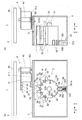
図1は、ネイルプリント装置1の概略の内部構成を示す図であり、このうち(a)が正面図であり、(b)が側面図である。
これらの図に示すように、本実施形態におけるネイルプリント装置1は、描画手段であるインクジェット描画部411とペン421とを備えた描画装置であり、これらの描画手段により複数の指Uの爪Tに順次描画を施すものである。
具体的に、ネイルプリント装置1は、ケース本体2と、このケース本体2内に収容された機枠3及び描画ヘッド4とを備えている。
[Configuration of Nail Print Device]
First, the configuration of the
FIG. 1 is a diagram illustrating a schematic internal configuration of the
As shown in these drawings, the
Specifically, the
ケース本体2の上面(天板)には、表示部26が設置されている。
表示部26は、例えば液晶ディスプレイ(LCD:Liquid Crystal Display)、有機エレクトロルミネッセンスディスプレイその他のフラットディスプレイ等で構成されている。
この表示部26には、例えば、描画を施す爪Tを有する指(以下、「印刷指Ut」という。)を撮影して得た爪画像(爪Tの画像を含む指画像)、この爪画像中に含まれる爪Tの輪郭線等の画像、爪Tに描画すべきデザイン画像を選択するためのデザイン選択画面、デザイン確認用のサムネイル画像、各種の指示を表示させる指示画面等が適宜表示される。
なお、表示部26の表面に各種の入力を行うためのタッチパネルが一体的に構成されていてもよい。
A
The
The
Note that a touch panel for performing various inputs may be integrally formed on the surface of the
また、ケース本体2の上面(天板)には、ユーザが各種操作を行う操作部25(図2参照)が設置されている。
操作部25には、例えば、ネイルプリント装置1の電源をONする電源スイッチ釦、動作を停止させる停止スイッチ釦、爪Tに描画するデザイン画像を選択するデザイン選択釦、描画開始を指示する描画開始釦等、各種の入力を行うための図示しない操作釦が配置されている。
An operation unit 25 (see FIG. 2) on which the user performs various operations is installed on the upper surface (top plate) of the
The
機枠3は、本実施形態においては、前方(指挿入方向の手前側)に開口する略箱状に形成されており、その内部に略円柱状の回転ステージ5を収容している。
また、機枠3の天板のうち、正面視で回転ステージ5の中心軸51の真上(真っ直ぐ上方)に位置する略中央部分には、上下方向に貫通する開口窓31が形成されている。この開口窓31は、後述するように、回転ステージ5上に載置される5つの指Uのうち、回転ステージ5の中心軸51の真上に位置するものを、印刷指Utとしてその爪Tの表面(すなわち、描画対象面)を機枠3の上方に露出させる。
In this embodiment, the
In addition, an
回転ステージ5は、本実施形態においては片手の5本の指Uの爪Tに順次描画を施すための指の載置台であり、図中の矢印Yと平行なネイルプリント装置1の前後方向(以下、「Y方向」という。)に沿った略円柱状に形成されている。この回転ステージ5は、Y方向に沿った中心軸51回りに回転可能に支持されている。
なお、回転ステージ5に載置可能な指Uの本数は、複数であれば特に限定されない。
In this embodiment, the
The number of fingers U that can be placed on the
回転ステージ5の外周面には、放射状に突出した6つの突起部52が、当該外周面のうちの略半周部に亘って周方向に均等間隔で、且つ、Y方向の略全長に亘って設けられている。これら6つの突起部52は、回転ステージ5に対して5本の指を周方向に位置決めするためのものであり、つまり、回転ステージ5の周方向に隣り合う2つの当該突起部52の間の5つの部分が、5本の指Uが個別に挿入される5つの指挿入部5aとなっている。各突起部52は、例えばゴムなどの弾性体で構成されるとともに、先端が丸い先細り状に形成されており、指Uを傷つけないように構成されている。
On the outer peripheral surface of the
回転ステージ5の外周部のうち、周方向に隣り合う2つの突起部52の間の部分(すなわち、指挿入部5a)には、Y方向に沿った中心軸531回りに回動可能な小型のローラ53がそれぞれ設けられている。各ローラ53は、回転ステージ5の外周部のうち前側(指挿入方向の手前側)の端部よりも後側の部分に亘ってY方向に長尺に設けられており、少なくとも各指Uの先端部が載置されるように構成されている。つまり、各ローラ53は、各指挿入部5aに挿入された指Uが載置される指載置部となっている。
また、各ローラ53は、回転ステージ5の径方向に沿って移動可能なように、当該径方向に沿ったガイド部材532に中心軸531が支持されるとともに、ローラ用並進モータ58(図2参照)が接続されており、このローラ用並進モータ58の駆動によって回転ステージ5の径方向に沿って移動可能なように構成されている。
Of the outer periphery of the
Further, each
回転ステージ5の外周面のうち、6つの突起部52が設けられた側とは反対側の略半周部には、回転ステージ5の周方向位置(回転位置)を定めるための5つの位置決め凹部54が形成されている。これら5つの位置決め凹部54は、5つの指挿入部5aに対応して設けられており、それぞれ対応する指挿入部5aに対し、回転ステージ5の外周面のうち中心軸51回りに反対側の部分(つまり、当該指挿入部5aから中心角180°だけ中心軸51回りに回転した部分)に設けられている。また、本実施形態の5つの位置決め凹部54は、回転ステージ5の外周面のうちの前側部分に、Y方向に沿った略半円柱状にそれぞれ形成されている。
本実施形態では、機枠3に固定されたロック装置55がこれら5つの位置決め凹部54に嵌まることにより、回転ステージ5が係止されてその回転が規制されるようになっており、これら回転ステージ5とロック装置55とで、本発明に係る指載置機構が構成されている。
Of the outer peripheral surface of the
In the present embodiment, the
ロック装置55は、5つの位置決め凹部54に対応するY方向位置であって、回転ステージ5の中心軸51の真下に位置するように、機枠3に固定されている。このロック装置55では、上方に開口する孔部551aがケース部材551に形成されるとともに、略棒状の係止部材552が上下方向に移動可能なように当該孔部551a内に挿通されている。そして、ケース部材551の孔部551a内では、その底部と係止部材552との間に付勢ばね553が設けられており、この付勢ばね553によって係止部材552が上方に付勢されている。また、係止部材552の上端は、例えば、Y方向に沿った中心軸を有する半円柱状に形成されている。
このような構成により、ロック装置55は、付勢ばね553の付勢力によって係止部材552を5つの位置決め凹部54のいずれかに係止させて、回転ステージ5の回転を規制するようになっている。このとき、係止部材552が係止された位置決め凹部54に対応する指挿入部5a内の指Uが、回転ステージ5の中心軸51の真上に位置して開口窓31から上方に露出する印刷指Utとなる。
The
With such a configuration, the
描画ヘッド4は、ケース本体2内のうち機枠3よりも上側の部分に設けられており、図中の矢印Xに沿ったネイルプリント装置1の左右方向(以下、「X方向」という。)と、Y方向とに移動可能に構成されている。より詳しくは、描画ヘッド4は、図示しないガイド部材上をX方向とY方向とに移動可能に支持されており、X方向移動モータ43(図2参照)の駆動によりガイド部材上をX方向に移動するとともに、Y方向移動モータ44(図2参照)の駆動によりガイド部材上をY方向に移動するように構成されている。
The drawing
描画ヘッド4には、インクジェット描画部411を保持するインクジェットホルダ41と、ペン421を保持するペンホルダ42とが隣り合って配置されている。
インクジェット描画部411は、例えば、イエロー(Y;YELLOW)、マゼンタ(M;MAGENTA)、シアン(C;CYAN)のインクに対応する図示しないインクカートリッジと、各インクカートリッジにおける描画対象(爪T)に対向する面(本実施形態では下面)に設けられた図示しないインク吐出部とが一体に形成されたインクカートリッジ一体型のヘッドである。インク吐出部は、それぞれの色のインクを噴射する複数のノズルからなるノズルアレイを備えており、インクジェット描画部411は、インクを微滴化し、インク吐出部から描画対象(爪T)の被描画面に対して直接にインクを吹き付けて描画を行う。なお、インクジェット描画部411は、上記3色のインクを吐出させるものに限定されず、その他のインクを貯留するインクカートリッジ及びインク吐出部を備えていてもよい。
In the
For example, the ink
ペンホルダ42には、1本のペン421が装着可能となっている。
ペン421は、爪Tの表面を描画対象面とし、先端部が描画対象面である爪Tの表面に接触して描画を施す筆記具である。
ペン421は、各種インクが収容された棒状のペン軸部の先端側(図中の下側)にペン先が設けられたものである。ペン軸部の内部に収容されるインクとしては、各種のインクが適用可能である。インクの粘度や色材の粒径(粒子の大きさ)等は特に限定されず、例えば、金銀のラメ入りのインクや白色のインク、UV硬化型のインクやジェルネイル、アンダーコート用インク、トップコート用インクやマニキュア液等も用いることができる。
また、描画ヘッド4のうちペンホルダ42の近傍には、ペン上下用モータ422(図2参照)を備える図示しないペン昇降機構が設けられており、当該ペン昇降機構によりペン421が上下方向に沿って移動可能となっている。
One
The
The
Further, a pen lifting mechanism (not shown) provided with a pen up / down motor 422 (see FIG. 2) is provided in the vicinity of the
本実施形態におけるペン421は、例えばペン先を爪Tの表面に押し当てることでペン軸部内に収容されているインクが染み出して描画する、ペン先がボールペンタイプとなったペンである。
なお、ペン421は、ペン先がボールペンタイプのものに限定されない。例えばフェルト状のペン先にインクを染み込ませて描画するサインペンタイプや、束ねた毛にインクを染み込ませて描画する筆ペンタイプのもの等であってもよい。また、ペン先の太さも各種のものを用意することができる。
また、ペンホルダ42に保持されるペン421は、全て同じタイプのペン先を有するものでもよいし、異なるタイプのペン先を有するものであってもよい。
The
The
Further, the
描画ヘッド4のうちの側端部(図1(a)における左端部)には、撮像装置61と、照明装置62と、高さ検出装置63とが、いずれも下向きの状態で固定配置されている。
このうち、撮像装置61は、例えば、200万画素程度以上の画素を有する固体撮像素子とレンズ等を備えて構成された小型カメラであり、機枠3の開口窓31から露出した印刷指Utの爪Tを撮影する。
照明装置62は、例えば白色LED等の光源である。本実施形態では、照明装置62は撮像装置61の側方に1つ配置されている。照明装置62は、下方に向けて光を照射して、少なくとも撮像装置61の下方の撮影範囲全体を照明する。撮像装置61に対する照明装置62の位置は一定となっている。なお、照明装置62を設ける数や、その配置等は図示例に限定されない。
高さ検出装置63は、例えば光学式のレーザー変位計などであり、当該高さ検出装置63から印刷指Utの爪Tまでの上下方向の距離を計測する。
An
Among these, the
The
The
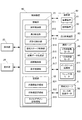
続いて、ネイルプリント装置1の制御構成について説明する。
図2は、ネイルプリント装置1の制御構成を示すブロック図である。
この図に示すように、ネイルプリント装置1は、当該ネイルプリント装置1の各部を制御する制御装置80を備えている。制御装置80は、図示しないCPU(Central Processing Unit)により構成される制御部81と、ROM(Read Only Memory)及びRAM(Random Access Memory)等(いずれも図示せず)で構成される記憶部82とを備えるコンピュータである。
Next, the control configuration of the
FIG. 2 is a block diagram illustrating a control configuration of the
As shown in this figure, the
記憶部82には、ネイルプリント装置1を動作させるための各種プログラムや各種データ等が格納されている。
具体的に、記憶部82のROMには、爪画像(撮影画像)から爪Tの傾斜角度を検出する角度検出プログラム、爪画像から爪Tの平面形状(すなわち、爪Tの輪郭)や爪Tの幅方向における湾曲形状、爪の幅、爪の面積等の各種の爪情報を検出するための爪情報検出プログラム、描画データを生成するための描画データ生成プログラム、描画処理を行うための描画プログラム等の各種プログラムが格納されており、これらのプログラムが制御装置80によって実行されることによって、ネイルプリント装置1の各部が統括制御される。
また、本実施形態における記憶部82には、撮像装置61によって取得されたユーザの印刷指Utの爪Tの爪画像(撮影画像)を記憶する爪画像記憶領域821、後述する爪形状検出部813によって検出された爪情報(爪Tの輪郭や爪Tの湾曲形状等)が記憶される爪情報記憶領域822、及び爪Tに描画されるネイルデザインの画像データを記憶するネイルデザイン記憶領域823等が設けられている。
The
Specifically, the ROM of the
Further, in the
制御部81は、機能的に見た場合、撮影制御部811、高さ検出部812、爪形状検出部813、回転ステージ制御部814、描画データ生成部815、描画制御部816、表示制御部817等を備えている。これら各機能部の機能は、制御部81のCPUと記憶部82のROMに記憶されたプログラムとの共働によって実現される。
When viewed functionally, the
撮影制御部811は、撮像装置61及び照明装置62を備えてなる撮影部60の動作を制御して、印刷指Utの爪Tの画像を含む指の画像である爪画像(撮影画像)を撮影させるものである。
本実施形態では、描画制御部816によって描画ヘッド4を爪Tの幅方向に移動させながら、撮影制御部811が、照明装置62により撮影範囲を照明しつつ撮像装置61により爪Tの幅方向における複数の位置・角度(例えば、爪Tの真上と爪Tの斜め上方等)から爪Tを撮影して、複数枚の爪画像(撮影画像)を取得させる。
The
In the present embodiment, the
高さ検出部812は、高さ検出装置63の動作を制御して、印刷指Utの爪Tの上下方向(高さ方向)の位置を検出するものである。
具体的に、高さ検出部812は、高さ検出装置63の動作を制御して、当該高さ検出装置63から印刷指Utの爪Tまでの上下方向の距離を計測させ、当該距離と、予め入力されたインクジェット描画部411の上下方向位置の情報とに基づいて、インクジェット描画部411のインク吐出部から印刷指Utの爪Tまでの上下方向の距離を検出する。
The
Specifically, the
爪形状検出部813は、撮像装置61によって撮影された爪Tの爪画像に基づいて、当該爪Tについての爪情報を検出するものである。
ここで、爪情報とは、例えば、爪Tの輪郭(爪形状、爪Tの水平位置のXY座標等)、爪Tの高さ(爪Tの上下方向の位置)、爪Tの幅方向における形状、すなわち、爪Tの表面の、XY平面に対する傾斜角度(爪Tの湾曲形状、爪Tの傾斜角度)等である。
The nail
Here, the nail information is, for example, the contour of the nail T (nail shape, XY coordinates of the horizontal position of the nail T), the height of the nail T (the vertical position of the nail T), and the width direction of the nail T. The shape, that is, the inclination angle of the surface of the nail T with respect to the XY plane (the curved shape of the nail T, the inclination angle of the nail T), and the like.
回転ステージ制御部814は、高さ検出装置63によって計測された印刷指Utの爪Tの上下方向位置等に基づいて、回転ステージ5の動作を制御するものである。
具体的に、回転ステージ制御部814は、ローラ用並進モータ58の動作を制御し、各ローラ53を径方向に移動させる。
The rotary
Specifically, the rotary
描画データ生成部815は、爪形状検出部813により検出された爪Tの爪情報に基づいて、描画ヘッド4により当該爪Tに施される描画用の描画データを生成するものである。
具体的に、描画データ生成部815は、爪形状検出部813により検出された爪Tの形状等に基づいてネイルデザインの画像データを拡大、縮小、切出し等することにより爪Tの形状に合わせ込む合せ込み処理を行う。また、描画データ生成部815は、爪形状検出部813により検出された爪Tの湾曲形状に応じて、爪Tに描画するように指定されたネイルデザインの画像データに適宜曲面補正等を行う。
The drawing
Specifically, the drawing
描画制御部816は、描画データ生成部815によって生成された描画データに基づいて、描画ヘッド4の動作を制御するものである。具体的に、描画制御部816は、爪Tに対してこの描画データにしたがった描画が施されるように、X方向移動モータ43及びY方向移動モータ44を動作制御して描画ヘッド4のXY平面状での位置を制御しつつ、ペン上下用モータ422及びインクジェット描画部411を動作制御して描画タイミングを制御する。
The
表示制御部817は、表示部26を制御して当該表示部26に各種の表示画面を表示させるものである。本実施形態では、表示制御部817は、例えばネイルデザインの選択画面やデザイン確認用のサムネイル画像、印刷指Utを撮影して取得した爪画像、各種の指示画面、操作画面等を表示部26に表示させるようになっている。
The
[ネイルプリント装置の動作]
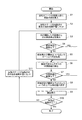
続いて、複数の指Uに順次描画を施すときのネイルプリント装置1の動作について説明する。
図3は、このときのネイルプリント装置1の動作の流れを示すフローチャートであり、図4及び図5は、ネイルプリント装置1の動作を説明するための図である。
なお、ここでは、インクジェット描画部411を使用し、ユーザの左手の5本の指Uに対して親指から小指に向かって順次各指Uの爪Tに描画を施す場合について説明する。
[Operation of nail print device]
Next, the operation of the
FIG. 3 is a flowchart showing an operation flow of the
Here, a case will be described in which the
まず、ユーザにより制御装置80が起動されると、表示制御部817は、表示部26にデザイン選択画面を表示させて、ユーザに所望のネイルデザインを選択させる。そして、ユーザが操作部25の操作釦等を操作して所望のネイルデザインを選択すると、操作部25から選択指示信号が出力されて、各指Uの爪Tに描画すべきネイルデザインが選択される。またこのとき、描画を施す指Uの本数なども、ユーザ操作に基づいて入力・設定される。
次に、表示制御部817は、5本の指Uを回転ステージ5の5つの指挿入部5aにセットするよう促す指示画面を表示部26に表示させる。
First, when the
Next, the
そして、図3に示すように、ユーザが左手で回転ステージ5を把持するようにして、その5本の指Uを回転ステージ5の5つの指挿入部5aに挿入すると(ステップS1)、表示制御部817は、最初に描画を施す指Uの爪Tを描画可能な描画位置に位置させるようユーザに促す指示画面を表示部26に表示させる。
そこで、ユーザは、最初に描画を施す指U(ここでは親指)が回転ステージ5の中心軸51の真上に位置するように、左手で回すようにして回転ステージ5を回転させる(ステップS2:図4(a))。
これにより、回転ステージ5の中心軸51の真上に配置された指Uが、機枠3の開口窓31から上方に露出し、その爪Tがインクジェット描画部411による描画の可能な描画位置に配置され、当該爪Tに描画が施される印刷指Utとされる。またこのとき、印刷指Utが挿入された指挿入部5aに対応する位置決め凹部54に、ロック装置55の係止部材552が「カチッ」というクリック音とともに係止され、この状態で回転ステージ5の回転が規制される。
As shown in FIG. 3, when the user holds the
Accordingly, the user rotates the
As a result, the finger U disposed right above the
次に、制御部81は、撮像装置61により印刷指Utの爪Tの爪画像を取得し、この爪画像に基づいて爪Tの傾きを検出する(ステップS3)。
具体的に、このステップでは、まず描画制御部816がX方向移動モータ43及びY方向移動モータ44の動作を制御して、撮像装置61が印刷指Utの爪Tの上方に位置するように描画ヘッド4を移動させた後、撮影制御部811が撮影部60を制御して、照明装置62により印刷指Utを照明しつつ撮像装置61により印刷指Utを撮影させる。これにより、撮影制御部811は、印刷指Utの爪Tの撮影画像(爪画像)を取得する。
そして、爪形状検出部813が、取得された爪Tの爪画像に基づいて、この爪Tの傾斜角度を含む当該爪Tについての爪情報を検出する。
Next, the
Specifically, in this step, first, the
Then, the nail
次に、制御部81は、ステップS3で検出された爪Tの爪情報に基づいて、この爪Tの傾斜角度が所定の閾値以下であるか否か、つまり、正常な描画が困難な程に爪Tが大きく傾斜していないか否かを判定し(ステップS4)、爪Tの傾斜角度が所定の閾値以下であると判定した場合には(ステップS4;Yes)、後述のステップS6へ処理を移行する。
Next, based on the nail information of the nail T detected in step S3, the
また、ステップS4において、爪Tの傾斜角度が所定の閾値を超えていると判定した場合(ステップS4;No)、表示制御部817は、印刷指Utを回して爪Tを真上に向けるようユーザに促す指示画面を、爪Tの傾斜状態に関する情報とともに表示部26に表示させる。
そして、ユーザは、表示部26に表示された爪Tの傾斜状態を参照しつつ、爪Tが真上を向いて傾斜角度が閾値以下となるように印刷指Utをローラ53上で回転させる(ステップS5:図4(b))。
In Step S4, when it is determined that the inclination angle of the nail T exceeds a predetermined threshold (Step S4; No), the
Then, the user rotates the printing finger Ut on the
次に、制御部81は、インクジェット描画部411のインク吐出部から印刷指Utの爪Tまでの上下方向の距離(以下、「印刷距離」という。)dを検出する(ステップS6:図5(a))。
具体的に、このステップでは、まず描画制御部816が、X方向移動モータ43及びY方向移動モータ44の動作を制御して、高さ検出装置63が印刷指Utの爪Tの上方に位置するように描画ヘッド4を移動させる。そして、高さ検出部812が、高さ検出装置63の動作を制御して当該高さ検出装置63から印刷指Utの爪Tまでの上下方向の距離を計測させ、この計測結果に基づいて、インクジェット描画部411のインク吐出部を基準とする印刷指Utの爪Tの上下方向位置、つまり印刷距離dを検出する。
Next, the
Specifically, in this step, first, the
次に、制御部81は、ステップS6で検出された印刷距離dが所定の閾値以下であるか否か、つまり、インクジェット描画部411と爪Tとが正常な描画を行える距離の範囲内にあるか否かを判定し(ステップS7)、印刷距離dが所定の閾値以下であると判定した場合には(ステップS7;Yes)、後述のステップS9へ処理を移行する。
Next, the
また、ステップS7において、印刷距離dが所定の閾値を超えていると判定した場合には(ステップS7;No)、制御部81は、印刷距離dが所定の閾値以下となるように、印刷指Utが載置されたローラ53を回転ステージ5の外径方向に移動させて、当該印刷指Utの爪Tの上下方向位置を調整する(ステップS8)。
具体的に、この場合には、回転ステージ制御部814がローラ用並進モータ58の動作を制御し、印刷距離dが所定の閾値以下となるまでローラ53を回転ステージ5の外径方向に移動させる。
なお、親指は最も太い指であるため、この親指の爪に描画した後に他の細い指の爪に描画する場合に、本ステップによる上下方向位置の調整が必要となりやすい。
If it is determined in step S7 that the printing distance d exceeds the predetermined threshold (step S7; No), the
Specifically, in this case, the rotary
Since the thumb is the thickest finger, it is likely to be necessary to adjust the vertical position in this step when drawing on the fingernail of the thumb and then drawing on the fingernail of another thin finger.
次に、制御部81は、印刷指Utの爪Tに対して描画を施す(ステップS9:図5(b)。
具体的には、まず描画データ生成部815が、上述のステップS3で検出された爪情報に基づいて、ネイルデザインの画像データの合せ込み処理や曲面補正等を行い、描画データを生成する。そして、描画制御部816が、生成された描画データに基づいて描画ヘッド4の動作を制御し、当該描画ヘッド4を移動させながら、印刷指Utの爪Tにインクジェット描画部411による描画を施す。
Next, the
Specifically, the drawing
次に、制御部81は、全ての指Uに対して描画が完了したか否かを判定し(ステップS10)、完了したと判定した場合には(ステップS10;Yes)、制御部81は、ネイルプリント装置1の描画動作を終了させる。
Next, the
また、ステップS10において、全ての指Uに対して描画が完了していない(描画していない指Uがある)と判定した場合には(ステップS10;No)、表示制御部817は、次に描画を施す指Uを描画位置に位置させるようユーザに促す指示画面を表示部26に表示させる。
そして、ユーザにより、左手で回すようにして回転ステージ5が回転され、直前のステップS9で描画が完了した印刷指Utの隣りの指Uであって未だ描画が施されていない指Uが、次に描画を施す指Uとして、機枠3の開口窓31から露出され、その爪Tが描画位置に配置される(ステップS11:図5(c))。すると、制御部81は、上述のステップS3へ処理を移行する。
これにより、この描画位置に配置された指Uが、次の印刷指Utとなる。またこのとき、当該次の印刷指Ut挿入された指挿入部5aに対応する位置決め凹部54に、ロック装置55の係止部材552が係止され、この状態で回転ステージ5の回転が規制される。
If it is determined in step S10 that drawing has not been completed for all fingers U (there is a finger U that has not been drawn) (step S10; No), the
Then, the
As a result, the finger U arranged at this drawing position becomes the next printing finger Ut. At this time, the locking
その後、この印刷指Utの爪Tに対して上述のステップS3〜S9の処理が実行されて当該爪Tにも同様に描画が施される。
そして、全ての指Uに対して描画が完了したと判定される(ステップS10;Yes)まで、回転ステージ5の回転により印刷指Utが隣りの指Uに順次送られて、その爪Tが描画位置に順次配置され、当該爪Tに描画が施されていく。
Thereafter, the processes of the above-described steps S3 to S9 are performed on the nail T of the printing finger Ut, and the nail T is similarly drawn.
Then, until it is determined that drawing has been completed for all the fingers U (step S10; Yes), the printing finger Ut is sequentially sent to the adjacent finger U by the rotation of the
[効果]
以上のように、本実施形態によれば、回転ステージ5をその中心軸51回りに回転させることにより、当該回転ステージ5上に載置された複数の指Uの爪Tが順次描画位置に配置されて当該爪Tに描画が施される。
このとき、複数の指Uは中心軸51を中心とする回転ステージ5の外周面上に載置されているため、単純な平板状の指載置部に手を載置させていた従来と異なり、描画位置において各指Uの爪Tを好適に回転ステージ5の外径方向に向けることができる。
したがって、複数の指の爪に好適に描画を施すことができる。
[effect]
As described above, according to the present embodiment, the claw T of the plurality of fingers U placed on the
At this time, since the plurality of fingers U are placed on the outer peripheral surface of the
Therefore, it is possible to suitably perform drawing on a plurality of fingernails.
また、回転ステージ5が略円柱状に形成されて、その外周面上に複数の指Uが載置されるため、描画位置において各指Uの爪Tをさらに好適に回転ステージ5の外径方向に向けることができる。
In addition, since the
また、回転ステージ5の周方向に隣り合う2つの突起部52の間(すなわち、指挿入部5a)にはローラ53がそれぞれ配置されているので、当該指挿入部5aに挿入された指Uをローラ53上で回転させることにより、その爪Tの向きを容易に調整することができる。
In addition, since the
また、回転ステージ5は、その外周面上に載置されたいずれかの指Uの爪Tが描画位置に配置される回転位置で、ロック装置55によって係止されるので、描画を施す指Uの爪Tを容易に描画位置に配置することができる。
Further, the
また、描画位置に配置された爪Tの上下方向位置が高さ検出部812により検出され、その検出結果に基づいて当該爪Tの上下方向の位置が調整される。
したがって、インクジェット描画部411と爪Tとの間の印刷距離dを、インクジェット描画部411が正常な描画を行うことのできる適正な距離の範囲内とした状態で、爪Tに描画を施すことができる。
In addition, the vertical position of the nail T arranged at the drawing position is detected by the
Therefore, it is possible to perform drawing on the nail T in a state where the printing distance d between the ink
[変形例]
なお、本発明を適用可能な実施形態は、上述した実施形態に限定されず、本発明の要旨を逸脱しない範囲で種々変形が可能であることは言うまでもない。
[Modification]
Needless to say, embodiments to which the present invention is applicable are not limited to the above-described embodiments, and various modifications can be made without departing from the scope of the present invention.
例えば、上記実施形態では、ユーザが回転ステージ5及びローラ53を回転させて所定の描画位置に指Uをセットする場合を例示したが、指載置機構の構成はこれに限定されない。
例えば、回転ステージ5及びローラ53をそれぞれの中心軸回りに回転駆動させるモータ及びこれを制御する回転制御部を設けて、回転ステージ5及びローラ53の回転が自動制御されるように構成してもよい。
この場合、回転ステージ5を係止してその回転を規制するための係止機構(回転ステージ5の位置決め凹部54及びロック装置55)は、設けなくともよい。
またこの場合、描画動作中に適宜回転ステージ5やローラ53の回転を制御して、爪Tの角度等を微調整可能としてもよい。
さらに、回転ステージ5及びローラ53をモータによって自動で回転駆動させて、係止機構を設けない場合には、描画手段としてのインクジェット描画部411及びペン421がY方向のみに移動し、X方向(つまり爪Tの幅方向)には移動しないように構成してもよい。そして、描画処理を行う際には、回転制御部によって回転ステージ5及びローラ53の回転駆動を制御することで、爪Tの幅方向への描画位置の移動を行うようにしてもよい。
For example, in the above embodiment, the case where the user sets the finger U at a predetermined drawing position by rotating the
For example, a motor that rotates the
In this case, the locking mechanism (the
In this case, the rotation of the
Further, when the
また、機枠3内部に、回転ステージ5の外周に沿うように各種機構を配置することによって、ある指Uの爪Tに描画位置においてインクジェット描画部411及びペン421による描画を行っている間に、並行して他の指Uの爪Tに各種の処理を行うことができるようにしてもよい。
例えば、描画位置よりも回転ステージ5の回転方向上流側に撮像装置61や下地用のインクを保持したペンを設けて、描画位置におけるインクジェット描画部411及びペン421による描画前に爪形状を検出するための撮影を行ったり、アンダーコートを施したりしてもよい。
また、描画位置よりも回転ステージの回転方向下流側に、ヒータやファン等で構成される乾燥機構やトップコート用のインクを保持したペンを設けて、インクジェット描画部411及びペン421による描画処理が終了した指Uの爪Tについて乾燥処理を行ったり、乾燥後にトップコートを施したりしてもよい。
なお、乾燥機構としてファンを設ける場合には、ファンにより発生した空気の流れによってインクジェット描画部411から吐出されるインクのミストが乱れないように、ファンと描画位置との間に空気の流れを遮断する遮蔽部材を配置することが好ましい。
In addition, by arranging various mechanisms along the outer periphery of the
For example, a pen holding the
Further, a drawing mechanism by the ink
When a fan is provided as a drying mechanism, the air flow is blocked between the fan and the drawing position so that the mist of ink discharged from the ink
また、回転ステージ5の外周面に設けられた突起部52は、指Uを周方向に位置決めできるものであれば突起状のものでなくともよく、当該突起部52に代えて、指Uの本数に対応した複数の凹部を回転ステージ5に設けてもよい。この場合、各凹部の底部にローラ53を配置すればよい。
Further, the
また、機枠3は、回転ステージ5をサイズ(外径やY方向の長さ)の異なるものに換装可能なように構成されていてもよい。このように構成すれば、サイズが異なる手の指にも好適に描画を施すことができる。
この場合、機枠3が回転ステージ5を昇降可能に支持するように構成することが好ましい。またこの場合には、回転ステージ5の各ローラ53は径方向に移動できなくともよい。
Further, the
In this case, it is preferable that the
また、回転ステージ5は、複数の指Uを載置する載置部を有して当該載置部の中心軸回りに回転可能に形成されていればよく、略円柱状に形成されていなくてもよいし、複数の指Uが外周面上に載置されなくともよい。
Moreover, the
以上、本発明のいくつかの実施形態を説明したが、本発明の範囲は、上述の実施の形態に限定するものではなく、特許請求の範囲に記載された発明の範囲とその均等の範囲を含む。
以下に、この出願の願書に最初に添付した特許請求の範囲に記載した発明を付記する。付記に記載した請求項の項番は、この出願の願書に最初に添付した特許請求の範囲の通りである。
〔付記〕
<請求項1>
所定の描画位置に配置された指の爪に描画を施す描画手段と、
前記描画手段の下方に配置され、複数の指を載置する載置部を有し、当該載置部の中心軸回りに回転可能に形成された回転ステージを備える指載置機構と、
を備え、
前記回転ステージを回転させることにより、当該回転ステージ上に載置された前記複数の指の爪を前記描画位置に順次配置可能に形成されていることを特徴とする描画装置。
<請求項2>
前記指載置機構の回転ステージは略円柱状に形成されており、前記載置部は前記略円柱状の外周面上に複数の指が載置されることを特徴とする請求項1に記載の描画装置。
<請求項3>
前記指載置機構は、前記回転ステージの外周面上に、前記複数の指を周方向に位置決めする複数の位置決め手段を備えていることを特徴とする請求項2に記載の描画装置。
<請求項4>
前記指載置機構は、前記複数の位置決め手段のうち前記回転ステージの周方向に隣り合う2つの位置決め手段の間にそれぞれ配置された調整用ローラを備えていることを特徴とする請求項3に記載の描画装置。
<請求項5>
前記指載置機構は、前記回転ステージの外周面上に載置されたいずれかの指の爪が前記描画位置に配置される位置で前記回転ステージを係止する係止機構を備えていることを特徴とする請求項1から請求項4のいずれか一項に記載の描画装置。
<請求項6>
前記指載置機構は、前記回転ステージを前記中心軸回りに回転させるモータ及び当該モータの動作を制御する制御部を備えていることを特徴とする請求項1から請求項5のいずれか一項に記載の描画装置。
<請求項7>
前記描画位置に配置された前記爪の高さ方向の位置を検出する高さ検出手段を備え、
前記指載置機構は、前記高さ検出手段による検出結果に基づいて、前記爪の高さ方向の位置を調整する昇降機構を備えていることを特徴とする請求項1から請求項6のいずれか一項に記載の描画装置。
<請求項8>
指の爪に描画を施す描画装置の制御方法であって、
前記描画装置は、
所定の描画位置に配置された指の爪に描画を施す描画手段と、
前記描画手段の下方に配置され、複数の指を載置する載置部を有し、当該載置部の中心軸回りに回転可能に形成された回転ステージを備える指載置機構と、
を備え、
前記回転ステージを回転させることにより、当該回転ステージ上に載置された前記複数の指の爪を前記描画位置に順次配置させることを特徴とする描画装置の制御方法。
As mentioned above, although several embodiment of this invention was described, the scope of the present invention is not limited to the above-mentioned embodiment, The range of the invention described in the claim, and its equivalent range Including.
The invention described in the scope of claims attached to the application of this application will be added below. The item numbers of the claims described in the appendix are as set forth in the claims attached to the application of this application.
[Appendix]
<Claim 1>
Drawing means for drawing on a fingernail arranged at a predetermined drawing position;
A finger placement mechanism that is disposed below the drawing means, has a placement portion on which a plurality of fingers are placed, and includes a rotation stage formed to be rotatable around the central axis of the placement portion;
With
A drawing apparatus, wherein the rotary stage is rotated so that the plurality of fingernails placed on the rotary stage can be sequentially arranged at the drawing position.
<Claim 2>
The rotary stage of the finger placement mechanism is formed in a substantially cylindrical shape, and the placement unit has a plurality of fingers placed on the substantially cylindrical outer peripheral surface. Drawing device.
<Claim 3>
The drawing apparatus according to
<Claim 4>
The said finger | toe mounting mechanism is provided with the roller for adjustment each arrange | positioned between the two positioning means adjacent to the circumferential direction of the said rotation stage among these positioning means. The drawing apparatus described.
<Claim 5>
The finger placement mechanism includes a locking mechanism that locks the rotation stage at a position where any fingernail placed on the outer peripheral surface of the rotation stage is disposed at the drawing position. The drawing apparatus according to any one of
<Claim 6>
The said finger placement mechanism is equipped with the motor which rotates the said rotation stage around the said central axis, and the control part which controls the operation | movement of the said motor, The any one of Claims 1-5 characterized by the above-mentioned. The drawing apparatus described in 1.
<Claim 7>
A height detecting means for detecting a position in the height direction of the nail arranged at the drawing position;
The said finger placement mechanism is provided with the raising / lowering mechanism which adjusts the position of the height direction of the said nail | claw based on the detection result by the said height detection means. The drawing apparatus according to
<Claim 8>
A control method of a drawing device for drawing on a fingernail,
The drawing device includes:
Drawing means for drawing on a fingernail arranged at a predetermined drawing position;
A finger placement mechanism that is disposed below the drawing means, has a placement portion on which a plurality of fingers are placed, and includes a rotation stage formed to be rotatable around the central axis of the placement portion;
With
A method of controlling a drawing apparatus, wherein the plurality of fingernails placed on the rotary stage are sequentially arranged at the drawing position by rotating the rotary stage.
1 ネイルプリント装置
3 機枠
31 開口窓
4 描画ヘッド
411 インクジェット描画部
421 ペン
5 回転ステージ
5a 指挿入部
51 中心軸
52 突起部
53 ローラ
54 位置決め凹部
55 ロック装置
61 撮像装置
62 照明装置
63 高さ検出装置
81 制御部
T 爪
U 指
Ut 印刷指
d 印刷距離
DESCRIPTION OF
Claims (8)
前記描画手段の下方に配置され、複数の指を載置する載置部を有し、当該載置部の中心軸回りに回転可能に形成された回転ステージを備える指載置機構と、
を備え、
前記回転ステージを回転させることにより、当該回転ステージ上に載置された前記複数の指の爪を前記描画位置に順次配置可能に形成されていることを特徴とする描画装置。 Drawing means for drawing on a fingernail arranged at a predetermined drawing position;
A finger placement mechanism that is disposed below the drawing means, has a placement portion on which a plurality of fingers are placed, and includes a rotation stage formed to be rotatable around the central axis of the placement portion;
With
A drawing apparatus, wherein the rotary stage is rotated so that the plurality of fingernails placed on the rotary stage can be sequentially arranged at the drawing position.
前記指載置機構は、前記高さ検出手段による検出結果に基づいて、前記爪の高さ方向の位置を調整する昇降機構を備えていることを特徴とする請求項1から請求項6のいずれか一項に記載の描画装置。 A height detecting means for detecting a position in the height direction of the nail arranged at the drawing position;
The said finger placement mechanism is provided with the raising / lowering mechanism which adjusts the position of the height direction of the said nail | claw based on the detection result by the said height detection means. The drawing apparatus according to claim 1.
前記描画装置は、
所定の描画位置に配置された指の爪に描画を施す描画手段と、
前記描画手段の下方に配置され、複数の指を載置する載置部を有し、当該載置部の中心軸回りに回転可能に形成された回転ステージを備える指載置機構と、
を備え、
前記回転ステージを回転させることにより、当該回転ステージ上に載置された前記複数の指の爪を前記描画位置に順次配置させることを特徴とする描画装置の制御方法。 A control method of a drawing device for drawing on a fingernail,
The drawing device includes:
Drawing means for drawing on a fingernail arranged at a predetermined drawing position;
A finger placement mechanism that is disposed below the drawing means, has a placement portion on which a plurality of fingers are placed, and includes a rotation stage formed to be rotatable around the central axis of the placement portion;
With
A method of controlling a drawing apparatus, wherein the plurality of fingernails placed on the rotary stage are sequentially arranged at the drawing position by rotating the rotary stage.
Priority Applications (1)
| Application Number | Priority Date | Filing Date | Title |
|---|---|---|---|
| JP2015255797A JP6808936B2 (en) | 2015-12-28 | 2015-12-28 | Drawing device and control method of drawing device |
Applications Claiming Priority (1)
| Application Number | Priority Date | Filing Date | Title |
|---|---|---|---|
| JP2015255797A JP6808936B2 (en) | 2015-12-28 | 2015-12-28 | Drawing device and control method of drawing device |
Publications (3)
| Publication Number | Publication Date |
|---|---|
| JP2017118897A true JP2017118897A (en) | 2017-07-06 |
| JP2017118897A5 JP2017118897A5 (en) | 2018-12-27 |
| JP6808936B2 JP6808936B2 (en) | 2021-01-06 |
Family
ID=59271344
Family Applications (1)
| Application Number | Title | Priority Date | Filing Date |
|---|---|---|---|
| JP2015255797A Active JP6808936B2 (en) | 2015-12-28 | 2015-12-28 | Drawing device and control method of drawing device |
Country Status (1)
| Country | Link |
|---|---|
| JP (1) | JP6808936B2 (en) |
Cited By (4)
| Publication number | Priority date | Publication date | Assignee | Title |
|---|---|---|---|---|
| WO2020110351A1 (en) * | 2018-11-30 | 2020-06-04 | 船井電機株式会社 | Printer |
| WO2021053931A1 (en) * | 2019-09-20 | 2021-03-25 | カシオ計算機株式会社 | Printing device, printing method, and program |
| JP2022046844A (en) * | 2020-09-11 | 2022-03-24 | カシオ計算機株式会社 | Printer |
| JP7351163B2 (en) | 2019-09-20 | 2023-09-27 | カシオ計算機株式会社 | Printing devices, terminal devices and printing systems |
Citations (10)
| Publication number | Priority date | Publication date | Assignee | Title |
|---|---|---|---|---|
| US4754769A (en) * | 1985-03-12 | 1988-07-05 | Salon Pro, Inc. | Nail dryer |
| JPH0215008U (en) * | 1988-07-16 | 1990-01-30 | ||
| JPH0274209A (en) * | 1988-07-26 | 1990-03-14 | Kulzer Gmbh | Irradiating device for a finger nail |
| JP2000287744A (en) * | 1999-04-07 | 2000-10-17 | New Goods Kk | Automatic manicure applier |
| JP3370345B2 (en) * | 1997-12-24 | 2003-01-27 | 株式会社ジットセレモニー | Nail art method and apparatus |
| JP2003534083A (en) * | 2000-05-26 | 2003-11-18 | パール テクノロジー ホールディングス リミテッド ライアビリティ カンパニー | Decoration of fingernails and toenails using inkjet |
| JP2006055508A (en) * | 2004-08-23 | 2006-03-02 | Megumi Kawakami | Nail table |
| JP3140109U (en) * | 2007-12-21 | 2008-03-13 | 坂井 公一 | Lighting device |
| JP2012135600A (en) * | 2010-12-10 | 2012-07-19 | Casio Computer Co Ltd | Nail print apparatus |
| JP2014050786A (en) * | 2012-09-06 | 2014-03-20 | Toyo Seikan Kaisha Ltd | Inkjet printer and printing method to cylindrical container |
-
2015
- 2015-12-28 JP JP2015255797A patent/JP6808936B2/en active Active
Patent Citations (10)
| Publication number | Priority date | Publication date | Assignee | Title |
|---|---|---|---|---|
| US4754769A (en) * | 1985-03-12 | 1988-07-05 | Salon Pro, Inc. | Nail dryer |
| JPH0215008U (en) * | 1988-07-16 | 1990-01-30 | ||
| JPH0274209A (en) * | 1988-07-26 | 1990-03-14 | Kulzer Gmbh | Irradiating device for a finger nail |
| JP3370345B2 (en) * | 1997-12-24 | 2003-01-27 | 株式会社ジットセレモニー | Nail art method and apparatus |
| JP2000287744A (en) * | 1999-04-07 | 2000-10-17 | New Goods Kk | Automatic manicure applier |
| JP2003534083A (en) * | 2000-05-26 | 2003-11-18 | パール テクノロジー ホールディングス リミテッド ライアビリティ カンパニー | Decoration of fingernails and toenails using inkjet |
| JP2006055508A (en) * | 2004-08-23 | 2006-03-02 | Megumi Kawakami | Nail table |
| JP3140109U (en) * | 2007-12-21 | 2008-03-13 | 坂井 公一 | Lighting device |
| JP2012135600A (en) * | 2010-12-10 | 2012-07-19 | Casio Computer Co Ltd | Nail print apparatus |
| JP2014050786A (en) * | 2012-09-06 | 2014-03-20 | Toyo Seikan Kaisha Ltd | Inkjet printer and printing method to cylindrical container |
Cited By (5)
| Publication number | Priority date | Publication date | Assignee | Title |
|---|---|---|---|---|
| WO2020110351A1 (en) * | 2018-11-30 | 2020-06-04 | 船井電機株式会社 | Printer |
| WO2021053931A1 (en) * | 2019-09-20 | 2021-03-25 | カシオ計算機株式会社 | Printing device, printing method, and program |
| JP7351163B2 (en) | 2019-09-20 | 2023-09-27 | カシオ計算機株式会社 | Printing devices, terminal devices and printing systems |
| JP2022046844A (en) * | 2020-09-11 | 2022-03-24 | カシオ計算機株式会社 | Printer |
| JP7294284B2 (en) | 2020-09-11 | 2023-06-20 | カシオ計算機株式会社 | printer |
Also Published As
| Publication number | Publication date |
|---|---|
| JP6808936B2 (en) | 2021-01-06 |
Similar Documents
| Publication | Publication Date | Title |
|---|---|---|
| US9930951B2 (en) | Drawing apparatus and drawing method for drawing apparatus | |
| JP6428411B2 (en) | Drawing apparatus and nail inclination detection method | |
| US9642436B2 (en) | Drawing device and method for detecting shape of nail in the same | |
| US9894979B2 (en) | Drawing apparatus and drawing method for drawing apparatus | |
| US9056491B2 (en) | Nail print apparatus | |
| US9463644B2 (en) | Drawing apparatus and drawing control method thereof | |
| US9894978B2 (en) | Drawing apparatus and drawing method for drawing apparatus | |
| JP6790513B2 (en) | Drawing device and drawing method of drawing device | |
| JP6808936B2 (en) | Drawing device and control method of drawing device | |
| JP2016010543A (en) | Drawing device | |
| US9205672B1 (en) | Drawing apparatus with a drawing head and a drawing tool and control method | |
| US9254026B2 (en) | Drawing apparatus and drawing method thereof | |
| US9649859B2 (en) | Drawing apparatus and method for controlling drawing by drawing apparatus | |
| US20150366317A1 (en) | Drawing apparatus | |
| JP2017055933A (en) | Nail shape detection device, drawing device, and nail shape detection method | |
| JP6213065B2 (en) | Nail printing apparatus and printing method for nail printing apparatus | |
| JP2015054153A (en) | Nail printing equipment, and printing method for nail printing equipment | |
| JP6733251B2 (en) | Drawing device and drawing method of drawing device | |
| JP6500529B2 (en) | Drawing apparatus and drawing method | |
| JP7184130B2 (en) | Rendering device and rendering method | |
| JP6825244B2 (en) | Drawing device and drawing method of drawing device | |
| JP2020185395A (en) | Drawing device and drawing method for the drawing device | |
| JP2017006351A (en) | Drawing device and drawing method of drawing device |
Legal Events
| Date | Code | Title | Description |
|---|---|---|---|
| A521 | Request for written amendment filed |
Free format text: JAPANESE INTERMEDIATE CODE: A523 Effective date: 20181114 |
|
| A621 | Written request for application examination |
Free format text: JAPANESE INTERMEDIATE CODE: A621 Effective date: 20181114 |
|
| A977 | Report on retrieval |
Free format text: JAPANESE INTERMEDIATE CODE: A971007 Effective date: 20190925 |
|
| A131 | Notification of reasons for refusal |
Free format text: JAPANESE INTERMEDIATE CODE: A131 Effective date: 20191001 |
|
| A521 | Request for written amendment filed |
Free format text: JAPANESE INTERMEDIATE CODE: A523 Effective date: 20191129 |
|
| A131 | Notification of reasons for refusal |
Free format text: JAPANESE INTERMEDIATE CODE: A131 Effective date: 20200428 |
|
| A521 | Request for written amendment filed |
Free format text: JAPANESE INTERMEDIATE CODE: A523 Effective date: 20200619 |
|
| TRDD | Decision of grant or rejection written | ||
| A01 | Written decision to grant a patent or to grant a registration (utility model) |
Free format text: JAPANESE INTERMEDIATE CODE: A01 Effective date: 20201110 |
|
| A61 | First payment of annual fees (during grant procedure) |
Free format text: JAPANESE INTERMEDIATE CODE: A61 Effective date: 20201123 |
|
| R150 | Certificate of patent or registration of utility model |
Ref document number: 6808936 Country of ref document: JP Free format text: JAPANESE INTERMEDIATE CODE: R150 |