JP2017116562A - Display device, control method for the same and program - Google Patents
Display device, control method for the same and program Download PDFInfo
- Publication number
- JP2017116562A JP2017116562A JP2015248143A JP2015248143A JP2017116562A JP 2017116562 A JP2017116562 A JP 2017116562A JP 2015248143 A JP2015248143 A JP 2015248143A JP 2015248143 A JP2015248143 A JP 2015248143A JP 2017116562 A JP2017116562 A JP 2017116562A
- Authority
- JP
- Japan
- Prior art keywords
- image
- video
- temperature
- unit
- light
- Prior art date
- Legal status (The legal status is an assumption and is not a legal conclusion. Google has not performed a legal analysis and makes no representation as to the accuracy of the status listed.)
- Pending
Links
Images


Classifications
-
- G—PHYSICS
- G09—EDUCATION; CRYPTOGRAPHY; DISPLAY; ADVERTISING; SEALS
- G09G—ARRANGEMENTS OR CIRCUITS FOR CONTROL OF INDICATING DEVICES USING STATIC MEANS TO PRESENT VARIABLE INFORMATION
- G09G3/00—Control arrangements or circuits, of interest only in connection with visual indicators other than cathode-ray tubes
- G09G3/20—Control arrangements or circuits, of interest only in connection with visual indicators other than cathode-ray tubes for presentation of an assembly of a number of characters, e.g. a page, by composing the assembly by combination of individual elements arranged in a matrix no fixed position being assigned to or needed to be assigned to the individual characters or partial characters
- G09G3/22—Control arrangements or circuits, of interest only in connection with visual indicators other than cathode-ray tubes for presentation of an assembly of a number of characters, e.g. a page, by composing the assembly by combination of individual elements arranged in a matrix no fixed position being assigned to or needed to be assigned to the individual characters or partial characters using controlled light sources
- G09G3/30—Control arrangements or circuits, of interest only in connection with visual indicators other than cathode-ray tubes for presentation of an assembly of a number of characters, e.g. a page, by composing the assembly by combination of individual elements arranged in a matrix no fixed position being assigned to or needed to be assigned to the individual characters or partial characters using controlled light sources using electroluminescent panels
- G09G3/32—Control arrangements or circuits, of interest only in connection with visual indicators other than cathode-ray tubes for presentation of an assembly of a number of characters, e.g. a page, by composing the assembly by combination of individual elements arranged in a matrix no fixed position being assigned to or needed to be assigned to the individual characters or partial characters using controlled light sources using electroluminescent panels semiconductive, e.g. using light-emitting diodes [LED]
- G09G3/3208—Control arrangements or circuits, of interest only in connection with visual indicators other than cathode-ray tubes for presentation of an assembly of a number of characters, e.g. a page, by composing the assembly by combination of individual elements arranged in a matrix no fixed position being assigned to or needed to be assigned to the individual characters or partial characters using controlled light sources using electroluminescent panels semiconductive, e.g. using light-emitting diodes [LED] organic, e.g. using organic light-emitting diodes [OLED]
-
- G—PHYSICS
- G09—EDUCATION; CRYPTOGRAPHY; DISPLAY; ADVERTISING; SEALS
- G09G—ARRANGEMENTS OR CIRCUITS FOR CONTROL OF INDICATING DEVICES USING STATIC MEANS TO PRESENT VARIABLE INFORMATION
- G09G3/00—Control arrangements or circuits, of interest only in connection with visual indicators other than cathode-ray tubes
- G09G3/001—Control arrangements or circuits, of interest only in connection with visual indicators other than cathode-ray tubes using specific devices not provided for in groups G09G3/02 - G09G3/36, e.g. using an intermediate record carrier such as a film slide; Projection systems; Display of non-alphanumerical information, solely or in combination with alphanumerical information, e.g. digital display on projected diapositive as background
- G09G3/003—Control arrangements or circuits, of interest only in connection with visual indicators other than cathode-ray tubes using specific devices not provided for in groups G09G3/02 - G09G3/36, e.g. using an intermediate record carrier such as a film slide; Projection systems; Display of non-alphanumerical information, solely or in combination with alphanumerical information, e.g. digital display on projected diapositive as background to produce spatial visual effects
-
- G—PHYSICS
- G09—EDUCATION; CRYPTOGRAPHY; DISPLAY; ADVERTISING; SEALS
- G09G—ARRANGEMENTS OR CIRCUITS FOR CONTROL OF INDICATING DEVICES USING STATIC MEANS TO PRESENT VARIABLE INFORMATION
- G09G3/00—Control arrangements or circuits, of interest only in connection with visual indicators other than cathode-ray tubes
- G09G3/20—Control arrangements or circuits, of interest only in connection with visual indicators other than cathode-ray tubes for presentation of an assembly of a number of characters, e.g. a page, by composing the assembly by combination of individual elements arranged in a matrix no fixed position being assigned to or needed to be assigned to the individual characters or partial characters
- G09G3/2003—Display of colours
-
- G—PHYSICS
- G06—COMPUTING; CALCULATING OR COUNTING
- G06F—ELECTRIC DIGITAL DATA PROCESSING
- G06F3/00—Input arrangements for transferring data to be processed into a form capable of being handled by the computer; Output arrangements for transferring data from processing unit to output unit, e.g. interface arrangements
- G06F3/14—Digital output to display device ; Cooperation and interconnection of the display device with other functional units
- G06F3/147—Digital output to display device ; Cooperation and interconnection of the display device with other functional units using display panels
-
- G—PHYSICS
- G09—EDUCATION; CRYPTOGRAPHY; DISPLAY; ADVERTISING; SEALS
- G09G—ARRANGEMENTS OR CIRCUITS FOR CONTROL OF INDICATING DEVICES USING STATIC MEANS TO PRESENT VARIABLE INFORMATION
- G09G2320/00—Control of display operating conditions
- G09G2320/02—Improving the quality of display appearance
- G09G2320/0247—Flicker reduction other than flicker reduction circuits used for single beam cathode-ray tubes
-
- G—PHYSICS
- G09—EDUCATION; CRYPTOGRAPHY; DISPLAY; ADVERTISING; SEALS
- G09G—ARRANGEMENTS OR CIRCUITS FOR CONTROL OF INDICATING DEVICES USING STATIC MEANS TO PRESENT VARIABLE INFORMATION
- G09G2320/00—Control of display operating conditions
- G09G2320/02—Improving the quality of display appearance
- G09G2320/0271—Adjustment of the gradation levels within the range of the gradation scale, e.g. by redistribution or clipping
- G09G2320/0276—Adjustment of the gradation levels within the range of the gradation scale, e.g. by redistribution or clipping for the purpose of adaptation to the characteristics of a display device, i.e. gamma correction
-
- G—PHYSICS
- G09—EDUCATION; CRYPTOGRAPHY; DISPLAY; ADVERTISING; SEALS
- G09G—ARRANGEMENTS OR CIRCUITS FOR CONTROL OF INDICATING DEVICES USING STATIC MEANS TO PRESENT VARIABLE INFORMATION
- G09G2320/00—Control of display operating conditions
- G09G2320/04—Maintaining the quality of display appearance
- G09G2320/041—Temperature compensation
-
- G—PHYSICS
- G09—EDUCATION; CRYPTOGRAPHY; DISPLAY; ADVERTISING; SEALS
- G09G—ARRANGEMENTS OR CIRCUITS FOR CONTROL OF INDICATING DEVICES USING STATIC MEANS TO PRESENT VARIABLE INFORMATION
- G09G2320/00—Control of display operating conditions
- G09G2320/06—Adjustment of display parameters
- G09G2320/0626—Adjustment of display parameters for control of overall brightness
-
- G—PHYSICS
- G09—EDUCATION; CRYPTOGRAPHY; DISPLAY; ADVERTISING; SEALS
- G09G—ARRANGEMENTS OR CIRCUITS FOR CONTROL OF INDICATING DEVICES USING STATIC MEANS TO PRESENT VARIABLE INFORMATION
- G09G2340/00—Aspects of display data processing
- G09G2340/04—Changes in size, position or resolution of an image
- G09G2340/0407—Resolution change, inclusive of the use of different resolutions for different screen areas
- G09G2340/0428—Gradation resolution change
-
- G—PHYSICS
- G09—EDUCATION; CRYPTOGRAPHY; DISPLAY; ADVERTISING; SEALS
- G09G—ARRANGEMENTS OR CIRCUITS FOR CONTROL OF INDICATING DEVICES USING STATIC MEANS TO PRESENT VARIABLE INFORMATION
- G09G3/00—Control arrangements or circuits, of interest only in connection with visual indicators other than cathode-ray tubes
- G09G3/20—Control arrangements or circuits, of interest only in connection with visual indicators other than cathode-ray tubes for presentation of an assembly of a number of characters, e.g. a page, by composing the assembly by combination of individual elements arranged in a matrix no fixed position being assigned to or needed to be assigned to the individual characters or partial characters
- G09G3/34—Control arrangements or circuits, of interest only in connection with visual indicators other than cathode-ray tubes for presentation of an assembly of a number of characters, e.g. a page, by composing the assembly by combination of individual elements arranged in a matrix no fixed position being assigned to or needed to be assigned to the individual characters or partial characters by control of light from an independent source
- G09G3/3406—Control of illumination source
Abstract
Description
本発明は、表示装置、表示装置の制御方法、及び、プログラムに関する。 The present invention relates to a display device, a display device control method, and a program.
従来、使用者が装着して使用する小型の表示装置が知られている。表示装置の多くは光を発する光源や発光部等を有するが、これら光源や発光部が動作に伴って発する熱が問題となることがあった。すなわち、表示装置の使用中に光源や発光部の温度が上昇し、適正な動作が可能な温度範囲を超える可能性があった。このため、光源や発光部を備える表示装置の発熱対策が種々提案された(例えば、特許文献1参照)。特許文献1は、使用者の頭部に装着した状態で使用されるHMD(Head Mounted Display:頭部装着型表示装置)を開示する。このHMDは、光源が発する熱を、フレキシブル回路基板を利用して効率よく吸収、伝達する構成を備え、この構成により光源の発熱に起因して起こる問題の回避を図っている。
Conventionally, a small display device that is worn and used by a user is known. Many display devices include a light source that emits light, a light-emitting unit, and the like, but heat generated by the operation of the light source and the light-emitting unit is sometimes problematic. That is, there is a possibility that the temperature of the light source or the light emitting unit rises during use of the display device and exceeds the temperature range in which proper operation is possible. For this reason, various countermeasures against heat generation of a display device including a light source and a light emitting unit have been proposed (see, for example, Patent Document 1).
特許文献1記載の装置のように、機械構造の工夫により、光源が発する熱を効率よく伝導して放熱する場合、表示装置の形状や構成が制限される。このため、光源や発光部を備える表示装置において、構造上の制約が小さい発熱対策が望まれていた。
本発明は上記事情に鑑みてなされたものであり、光を発して画像を視認させる表示装置において、発光に伴う温度上昇に対応して、動作温度を適正な範囲内に維持することを目的とする。
As in the device described in
The present invention has been made in view of the above circumstances, and an object of the present invention is to maintain an operating temperature within an appropriate range in a display device that emits light and visually recognizes an image in response to a temperature increase associated with light emission. To do.
上記目的を達成するために、本発明の表示装置は、使用者が装着して使用する表示装置であって、映像光を生じさせる第1映像素子、及び、第2映像素子と、前記第1映像素子により生じる映像光に基づき前記使用者の右眼に画像を視認させ、前記第2映像素子により生じる映像光に基づき前記使用者の左眼に画像を視認させる表示部と、前記第1映像素子及び前記第2映像素子のそれぞれの温度を検出する温度検出部と、前記温度検出部により検出した温度に基づき前記第1映像素子及び前記第2映像素子の少なくともいずれかが生じさせる映像光の輝度を制御する制御部と、を備えることを特徴とする。
本発明によれば、映像素子の温度変化に対応して映像素子により生じる光の輝度を調整することにより、映像素子の動作温度を適正な範囲内に維持できる。
In order to achieve the above object, a display device according to the present invention is a display device worn and used by a user, and includes a first image element and a second image element that generate image light, and the first image element. A display unit that causes the right eye of the user to visually recognize an image based on video light generated by the video element, and causes the left eye of the user to visually recognize an image based on video light generated from the second video element; A temperature detector that detects the temperature of each of the element and the second image element; and image light generated by at least one of the first image element and the second image element based on the temperature detected by the temperature detector. And a control unit for controlling luminance.
According to the present invention, the operating temperature of the image element can be maintained within an appropriate range by adjusting the luminance of light generated by the image element in response to the temperature change of the image element.
また、本発明は、上記表示装置において、前記制御部は、前記第1映像素子及び前記第2映像素子の温度に基づき、前記第1映像素子及び前記第2映像素子が生じさせる映像光の輝度を、前記第1映像素子及び前記第2映像素子のうち低輝度側の輝度に合わせる制御を行うこと、を特徴とする。
本発明によれば、第1映像素子及び第2映像素子により生じる映像光の輝度を低輝度の側に合わせるので、表示画像の視認性を極端に変化させることなく、映像素子の温度上昇に対応して輝度を調整できる。これにより、映像素子の動作温度を適正な範囲内に維持できる。
In the display device according to the aspect of the invention, the control unit may be configured to control the luminance of the video light generated by the first video element and the second video element based on the temperatures of the first video element and the second video element. Is controlled to match the luminance on the lower luminance side of the first video element and the second video element.
According to the present invention, the brightness of the image light generated by the first image element and the second image element is adjusted to the low-luminance side, so that the temperature of the image element can be increased without drastically changing the visibility of the display image. Brightness can be adjusted. Thereby, the operating temperature of the image element can be maintained within an appropriate range.
また、本発明は、上記表示装置において、前記制御部は、前記第1映像素子及び前記第2映像素子のいずれかの温度が閾値以上となった場合に、前記第1映像素子及び前記第2映像素子が生じさせる映像光の輝度を、前記第1映像素子及び前記第2映像素子のうち低輝度側に合わせる制御を行うこと、を特徴とする。
本発明によれば、第1映像素子及び第2映像素子のいずれかの温度の上昇に対応して、表示画像の視認性を極端に変化させることなく、映像素子により生じる映像光輝度を低下させることができ、映像素子の動作温度を適正な範囲内に維持できる。
Further, according to the present invention, in the display device, when the temperature of either the first video element or the second video element is equal to or higher than a threshold value, the control unit is configured to display the first video element and the second video element. Control is performed to adjust the luminance of the video light generated by the video device to the lower luminance side of the first video device and the second video device.
According to the present invention, in response to an increase in the temperature of either the first video element or the second video element, the video light luminance generated by the video element is reduced without drastically changing the visibility of the display image. And the operating temperature of the image element can be maintained within an appropriate range.
また、本発明は、上記表示装置において、前記制御部は、前記第1映像素子及び前記第2映像素子の温度に基づき、前記第1映像素子及び前記第2映像素子が生じさせる映像光の輝度を、前記表示部の外光の照度に対応する輝度に合わせる制御を行うこと、を特徴とする。
本発明によれば、第1映像素子及び第2映像素子により生じる映像光の輝度を、表示装置の環境光の明るさに合わせて調整することにより、表示画像の視認性を極端に低下させることなく、輝度を調整できる。
In the display device according to the aspect of the invention, the control unit may be configured to control the luminance of the video light generated by the first video element and the second video element based on the temperatures of the first video element and the second video element. Is controlled to match the luminance corresponding to the illuminance of the outside light of the display unit.
According to the present invention, the visibility of the displayed image is extremely reduced by adjusting the luminance of the video light generated by the first video device and the second video device according to the brightness of the ambient light of the display device. The brightness can be adjusted.
また、本発明は、上記表示装置において、前記表示部は、前記第1映像素子により生じる映像光及び前記第2映像素子により生じる映像光に基づく画像を前記使用者に視認させ、外景を透過して前記使用者に視認させる構成を有し、前記制御部は、前記第1映像素子及び前記第2映像素子が生じさせる映像光の輝度を、前記表示部を透過する外光の照度に対応する輝度に合わせる制御を行うこと、を特徴とする。
本発明によれば、使用者が、表示部を透過する外光と第1映像素子及び第2映像素子により生じる映像光とを重ねて視認する構成において、外光の照度に合わせて第1映像素子及び第2映像素子により生じる映像光の輝度を調整する。これにより、外光により視認される外景および表示画像の両方の視認性を確保し、第1映像素子及び第2映像素子により生じる映像光の輝度を調整できる。
In the display device according to the aspect of the invention, the display unit may allow the user to visually recognize an image based on the video light generated by the first video element and the video light generated by the second video element, and transmit the outside scene. The control unit corresponds to the luminance of the video light generated by the first video element and the second video element to the illuminance of external light transmitted through the display unit. It is characterized by performing control in accordance with luminance.
According to the present invention, in the configuration in which the user visually recognizes the external light transmitted through the display unit and the video light generated by the first video element and the second video element, the first video is matched with the illuminance of the external light. The brightness of the image light generated by the element and the second image element is adjusted. Thereby, the visibility of both the outside scene visually recognized by the external light and the display image can be ensured, and the luminance of the video light generated by the first video element and the second video element can be adjusted.
また、本発明は、上記表示装置において、前記表示部は、前記第1映像素子により生じる映像光を前記使用者の右眼に導き、前記第2映像素子により生じる映像光を前記使用者の左眼に導く光学部を備えること、を特徴とする。
本発明によれば、使用者の左右の眼に視認される画像の輝度のバランスを適正に保ちながら、映像素子の温度上昇に対応して輝度を調整できる。
Further, according to the present invention, in the display device, the display unit guides image light generated by the first image element to the right eye of the user, and outputs image light generated by the second image element to the left side of the user. It is characterized by comprising an optical part that leads to the eye.
According to the present invention, it is possible to adjust the luminance in response to the temperature rise of the video device while appropriately maintaining the luminance balance of the image visually recognized by the left and right eyes of the user.
また、本発明は、上記表示装置において、前記第1映像素子、及び前記第2映像素子は、それぞれ前記使用者の頭部の側方に位置すること、を特徴とする。
本発明によれば、使用者の頭部の側方に位置する映像素子の温度上昇に対応して、輝度を調整し、映像素子の動作温度を適正な範囲内に維持できる。
Further, the present invention is characterized in that, in the display device, the first image element and the second image element are respectively located on a side of the user's head.
According to the present invention, it is possible to adjust the luminance and maintain the operating temperature of the video device within an appropriate range in response to the temperature rise of the video device located on the side of the user's head.
また、本発明は、上記表示装置において、前記制御部は、前記第1映像素子または前記第2映像素子の少なくともいずれかが、前記使用者の身体への影響に基づき定められた閾値以上となった場合に、前記第1映像素子及び前記第2映像素子の少なくともいずれかが生じさせる映像光の輝度を低下させる制御を行うこと、を特徴とする。
本発明によれば、使用者の頭部の側方に位置する映像素子の温度が、使用者の身体への影響が懸念される温度になる前に、映像素子の輝度を調整することにより、映像素子の温度上昇に対処できる。
Further, according to the present invention, in the display device, the control unit is configured such that at least one of the first video element and the second video element is equal to or higher than a threshold value determined based on an influence on the body of the user. In this case, control is performed to reduce the luminance of video light generated by at least one of the first video device and the second video device.
According to the present invention, by adjusting the brightness of the video device before the temperature of the video device located on the side of the user's head becomes a temperature at which the influence on the user's body is concerned, It can cope with the temperature rise of the image element.
また、本発明は、上記表示装置において、前記第1映像素子及び前記第2映像素子は、発光体を実装したパネルを備え、前記温度検出部は前記発光体の裏側で前記パネルに接して配置されること、を特徴とする。
本発明によれば、発光に伴う映像素子の温度変化を的確に検出できる。
In the display device according to the aspect of the invention, the first image element and the second image element include a panel on which a light emitter is mounted, and the temperature detection unit is disposed in contact with the panel on the back side of the light emitter. It is characterized by that.
According to the present invention, it is possible to accurately detect a temperature change of an image element due to light emission.
また、本発明は、上記表示装置において、前記第1映像素子及び前記第2映像素子は、それぞれ、複数の色光を含む画像光を出力する前記パネルと、前記パネルを駆動する駆動部とを備え、前記温度検出部は前記駆動部に実装されて前記パネルの温度を検出すること、を特徴とする。
本発明によれば、パネルと駆動部と温度検出部とを備える表示装置をコンパクトな構成で実現できる。
In the display device, the first video element and the second video element each include the panel that outputs image light including a plurality of color lights, and a drive unit that drives the panel. The temperature detection unit is mounted on the driving unit and detects the temperature of the panel.
ADVANTAGE OF THE INVENTION According to this invention, a display apparatus provided with a panel, a drive part, and a temperature detection part is realizable with a compact structure.
また、本発明は、上記表示装置において、前記パネルが発する画像光のガンマ値を補正する補正パラメーターを、前記パネルの温度ごとに記憶する記憶部を備え、前記制御部は、前記温度検出部により検出した温度に基づき前記第1映像素子及び前記第2映像素子の少なくともいずれかが生じさせる映像光の輝度を制御し、前記温度検出部により検出した温度に対応する前記補正パラメーターを用いて前記パネルのガンマ補正を実行すること、を特徴とする。
本発明によれば、パネルが発する光の色を補正することにより、表示画像の品位を高品位に維持できる。
The display device may further include a storage unit that stores a correction parameter for correcting the gamma value of the image light emitted from the panel for each temperature of the panel, and the control unit is configured by the temperature detection unit. Based on the detected temperature, the brightness of image light generated by at least one of the first image element and the second image element is controlled, and the panel is corrected using the correction parameter corresponding to the temperature detected by the temperature detection unit. Performing a gamma correction.
According to the present invention, the quality of a display image can be maintained at a high quality by correcting the color of light emitted from the panel.
また、本発明は、上記表示装置において、前記第1映像素子及び前記第2映像素子は、それぞれ、光源部と、前記光源部が発する光を変調して複数の色光を含む画像光を出力する変調装置と、前記変調装置を駆動する変調装置駆動部とを備え、前記温度検出部は前記変調装置駆動部とともに実装されること、を特徴とする。
本発明によれば、光源部が発する光を変調装置で変調して画像光を出力する構成において、光源及び変調装置の温度の変化を的確に検出できる。
In the display device according to the aspect of the invention, each of the first video element and the second video element modulates light emitted from the light source unit and the light source unit and outputs image light including a plurality of color lights. The apparatus includes a modulation device and a modulation device driving unit that drives the modulation device, and the temperature detection unit is mounted together with the modulation device driving unit.
ADVANTAGE OF THE INVENTION According to this invention, in the structure which modulates the light which a light source part emits with a modulation apparatus, and outputs image light, the change of the temperature of a light source and a modulation apparatus can be detected exactly.
また、上記目的を達成するために、本発明の表示装置の制御方法は、使用者により装着されて使用され、映像光を生じさせる第1映像素子及び第2映像素子と、前記第1映像素子により生じる映像光に基づき前記使用者の右眼に画像を視認させ、前記第2映像素子により生じる映像光に基づき前記使用者の左眼に画像を視認させる表示部とを備える表示装置を制御して、前記第1映像素子及び前記第2映像素子のそれぞれの温度を検出し、検出した温度に基づき前記第1映像素子及び前記第2映像素子の少なくともいずれかが生じさせる映像光の輝度を制御すること、を特徴とする。
本発明によれば、映像素子の温度変化に対応して映像素子により生じる映像光の輝度を調整することにより、映像素子の動作温度を適正な範囲内に維持できる。
In order to achieve the above object, a display device control method according to the present invention includes a first image element and a second image element that are worn and used by a user to generate image light, and the first image element. A display device comprising: a display unit configured to cause the right eye of the user to visually recognize an image based on video light generated by the second image element and to visually recognize an image to the left eye of the user based on video light generated by the second video element; The temperature of each of the first video element and the second video element is detected, and the brightness of the video light generated by at least one of the first video element and the second video element is controlled based on the detected temperature. It is characterized by doing.
According to the present invention, the operating temperature of the video device can be maintained within an appropriate range by adjusting the luminance of the video light generated by the video device in response to the temperature change of the video device.
また、上記目的を達成するために、本発明は、使用者により装着されて使用され、映像光を生じさせる第1映像素子及び第2映像素子と、前記第1映像素子により生じる映像光に基づき前記使用者の右眼に画像を視認させ、前記第2映像素子により生じる映像光に基づき前記使用者の左眼に画像を視認させる表示部とを備える表示装置を制御するコンピューターが実行可能なプログラムであって、前記第1映像素子及び前記第2映像素子のそれぞれの温度を検出し、検出した温度に基づき前記第1映像素子及び前記第2映像素子の少なくともいずれかが生じさせる映像光の輝度を制御するためのプログラムである。
本発明によれば、映像素子の温度変化に対応して映像素子により生じる映像光の輝度を調整することにより、映像素子の動作温度を適正な範囲内に維持できる。
In order to achieve the above object, the present invention is based on the first image element and the second image element that are worn and used by a user and generate image light, and the image light generated by the first image element. A computer-executable program for controlling a display device including a display unit that causes an image to be visually recognized by the user's right eye and that causes the user's left eye to visually recognize an image based on video light generated by the second video element. And detecting the temperature of each of the first image element and the second image element, and the luminance of the image light generated by at least one of the first image element and the second image element based on the detected temperature It is a program for controlling.
According to the present invention, the operating temperature of the video device can be maintained within an appropriate range by adjusting the luminance of the video light generated by the video device in response to the temperature change of the video device.
本発明は、上述した表示装置、表示装置の制御方法、及びプログラム以外の種々の形態で実現することも可能である。例えば、上記のプログラムを記録した記録媒体、プログラムを配信するサーバー装置、上記プログラムを伝送する伝送媒体、上記プログラムを搬送波内に具現化したデータ信号等の形態で実現できる。 The present invention can also be realized in various forms other than the above-described display device, display device control method, and program. For example, the present invention can be realized in the form of a recording medium that records the program, a server device that distributes the program, a transmission medium that transmits the program, a data signal that embodies the program in a carrier wave, and the like.
図1は、本発明を適用した実施形態に係るHMD(Head Mounted Display:頭部装着型表示装置)100の外観構成を示す説明図である。
HMD100は、使用者の頭部に装着された状態で使用者に虚像を視認させる画像表示部20(表示部)と、画像表示部20を制御する制御装置10と、を備える表示装置である。また、制御装置10は、使用者の操作を受け付ける各種のボタン、スイッチやトラックパッド14を備え、使用者がHMD100を操作するコントローラーとして機能する。
FIG. 1 is an explanatory diagram showing an external configuration of an HMD (Head Mounted Display) 100 according to an embodiment to which the present invention is applied.
The
画像表示部20は、使用者の頭部に装着される装着体であり、本実施形態では眼鏡形状を有する。画像表示部20は、右保持部21と、左保持部23と、前部フレーム27とを有する本体に、右表示ユニット22(第1映像素子)、左表示ユニット24(第2映像素子)、右導光板26、及び左導光板28を備える。
右保持部21及び左保持部23は、それぞれ、前部フレーム27の両端部から後方に延び、眼鏡のテンプル(つる)のように、使用者の頭部に画像表示部20を保持する。ここで、前部フレーム27の両端部のうち、画像表示部20の装着状態において使用者の右側に位置する端部を端部ERとし、使用者の左側に位置する端部を端部ELとする。右保持部21は、前部フレーム27の端部ERから、画像表示部20装着状態において使用者の右側頭部に対応する位置まで延伸して設けられる。左保持部23は、端部ELから、画像表示部20の装着状態において使用者の左側頭部に対応する位置まで延伸して設けられる。
The
Each of the
右導光板26及び左導光板28は、前部フレーム27に設けられる。右導光板26は、画像表示部20の装着状態において使用者の右眼の眼前に位置し、右眼に画像を視認させる。左導光板28は、画像表示部20の装着状態において使用者の左眼の眼前に位置し、左眼に画像を視認させる。
The right
前部フレーム27は、右導光板26の一端と左導光板28の一端とを互いに連結した形状を有し、この連結位置は、使用者が画像表示部20を装着する装着状態で、使用者の眉間に対応する。前部フレーム27は、右導光板26と左導光板28との連結位置において、画像表示部20の装着状態で使用者の鼻に当接する鼻当て部を設けてもよい。この場合、鼻当て部と右保持部21及び左保持部23とにより画像表示部20を使用者の頭部に保持できる。また、右保持部21及び左保持部23に、画像表示部20の装着状態において使用者の後頭部に接するベルト(図示略)を連結してもよく、この場合、ベルトによって画像表示部20を使用者の頭部に保持できる。
The
右表示ユニット22は、右導光板26による画像の表示に係るユニットであり、右保持部21に設けられ、装着状態において使用者の右側頭部の近傍に位置する。左表示ユニット24は、左導光板28による画像の表示に係るユニットであり、左保持部23に設けられ、装着状態において使用者の左側頭部の近傍に位置する。なお、右表示ユニット22及び左表示ユニット24を総称して単に「表示駆動部」とも呼ぶ。
The
本実施形態の右導光板26及び左導光板28は、光透過性の樹脂等によって形成される光学部であり、例えばプリズムであり、右表示ユニット22及び左表示ユニット24が出力する画像光を、使用者の眼に導く。
また、右導光板26及び左導光板28の表面に、調光板(図示略)を設けてもよい。調光板は、光の波長域により透過率が異なる薄板上の光学素子であり、いわゆる波長フィルターとして機能する。調光板は、例えば、使用者の眼の側とは反対の側である前部フレーム27の表側を覆うように配置される。この調光板の光学特性を適宜選択することにより、可視光、赤外光及び紫外光等の任意の波長域の光の透過率を調整することができ、外部から右導光板26及び左導光板28に入射し、右導光板26及び左導光板28を透過する外光の光量を調整できる。
The right
A light control plate (not shown) may be provided on the surfaces of the right
画像表示部20は、詳細は後述するが、右表示ユニット22及び左表示ユニット24がそれぞれ生成する画像光を、右導光板26及び左導光板28に導き、この画像光によって虚像を使用者に視認させることによって、画像を表示する。使用者の前方から、右導光板26及び左導光板28を透過して外光が使用者の眼に入射する場合、使用者の眼には、虚像を構成する画像光および外光が入射することとなり、虚像の視認性が外光の強さに影響される。このため、例えば前部フレーム27に調光板を装着し、調光板の光学特性を適宜選択あるいは調整することによって、虚像の視認のしやすさを調整できる。典型的な例では、HMD100を装着した使用者が少なくとも外の景色を視認できる程度の光透過性を有する調光板を用いることができる。また、調光板を用いると、右導光板26及び左導光板28を保護し、右導光板26及び左導光板28の損傷や汚れの付着等を抑制する効果が期待できる。調光板は、前部フレーム27、或いは、右導光板26及び左導光板28のそれぞれに対し着脱可能としてもよく、複数種類の調光板を交換して装着可能としてもよく、調光板を省略してもよい。
As will be described in detail later, the
カメラ61は、画像表示部20の前部フレーム27に配設される。カメラ61は、使用者が画像表示部20を装着した状態で視認する外景方向を撮像することが望ましく、前部フレーム27の前面において、右導光板26及び左導光板28を透過する外光を遮らない位置に設けられる。図1の例では、カメラ61が前部フレーム27の端部ER側に配置される。カメラ61は、端部EL側に配置されてもよく、右導光板26と左導光板28との連結部に配置されてもよい。
The
カメラ61は、CCDやCMOS等の撮像素子及び撮像レンズ等を備えるデジタルカメラであり、本実施形態のカメラ61は単眼カメラであるが、ステレオカメラで構成してもよい。カメラ61は、HMD100の表側方向、換言すれば、HMD100を装着した状態における使用者の視界方向の少なくとも一部の外景(実空間)を撮像する。別の表現では、カメラ61は、使用者の視界と重なる範囲または方向を撮像し、使用者が注視する方向を撮像するということもできる。カメラ61の画角の広さは適宜設定可能であるが、本実施形態では、後述するように、使用者が右導光板26及び左導光板28を通して視認する外界を含む。より好ましくは、右導光板26及び左導光板28を透過して視認可能な使用者の視界の全体を撮像できるように、カメラ61の撮像範囲が設定される。
カメラ61は、制御部150(図5)が備える撮像制御部149の制御に従って撮像を実行し、撮像画像データを撮像制御部149に出力する。
The
The
HMD100は、予め設定された測定方向に位置する測定対象物までの距離を検出する距離センサー(図示略)を備えてもよい。距離センサーは、例えば、前部フレーム27において右導光板26と左導光板28との連結部分に配置できる。この場合、画像表示部20の装着状態において、距離センサーの位置は、水平方向では使用者の両眼のほぼ中間であり、鉛直方向では使用者の両眼より上である。距離センサーの測定方向は、例えば、前部フレーム27の表側方向とすることができ、言い換えればカメラ61の撮像方向と重複する方向である。距離センサーは、例えば、LEDやレーザーダイオード等の光源と、光源が発する光が測定対象物に反射する反射光を受光する受光部とを有する構成とすることができる。距離センサーは、制御部150の制御に従い、三角測距処理や時間差に基づく測距処理を実行すればよい。また、距離センサーは、超音波を発する音源と、測定対象物で反射する超音波を受信する検出部とを備える構成としてもよい。この場合、距離センサーは、制御部150の制御に従い、超音波の反射までの時間差に基づき測距処理を実行すればよい。
The
図2は、画像表示部20が備える光学系の構成を示す要部平面図である。図2には説明のため使用者の左眼LE及び右眼REを図示する。
図2に示すように、右表示ユニット22と左表示ユニット24とは、左右対称に構成される。使用者の右眼REに画像を視認させる構成として、右表示ユニット22は、画像光を発するOLED(Organic Light Emitting Diode)ユニット221と、OLEDユニット221が発する画像光Lを導くレンズ群等を備えた右光学系251とを備える。画像光Lは、右光学系251により右導光板26に導かれる。
FIG. 2 is a principal plan view showing the configuration of the optical system provided in the
As shown in FIG. 2, the
OLEDユニット221は、OLEDパネル223と、OLEDパネル223を駆動するOLED駆動回路225とを有する。OLEDパネル223は、有機エレクトロルミネッセンスにより発光してR(赤)、G(緑)、B(青)の色光をそれぞれ発する発光素子を、マトリクス状に配置して構成される、自発光型の表示パネルである。OLEDパネル223は、R、G、Bの素子を1個ずつ含む単位を1画素として、複数の画素を備え、マトリクス状に配置される画素により画像を形成する。OLED駆動回路225は、制御部150(図5)の制御に従って、OLEDパネル223が備える発光素子の選択及び発光素子への通電を実行して、OLEDパネル223の発光素子を発光させる。OLED駆動回路225は、OLEDパネル223の裏面すなわち発光面の裏側に、ボンディング等により固定される。OLED駆動回路225は、例えばOLEDパネル223を駆動する半導体デバイスで構成され、OLEDパネル223の裏面に固定される基板(図示略)に実装されてもよい。この基板には、後述する温度センサー217が実装される。
なお、OLEDパネル223は、白色に発光する発光素子をマトリクス状に配置し、R、G、Bの各色に対応するカラーフィルターを重ねて配置する構成であってもよい。また、R、G、Bの色光をそれぞれ放射する発光素子に加え、W(白)の光を発する発光素子を備えるWRGB構成のOLEDパネル223を用いてもよい。
The
Note that the
右光学系251は、OLEDパネル223から射出された画像光Lを並行状態の光束にするコリメートレンズを有する。コリメートレンズにより並行状態の光束にされた画像光Lは、右導光板26に入射する。右導光板26の内部において光を導く光路には、画像光Lを反射する複数の反射面が形成される。画像光Lは、右導光板26の内部で複数回の反射を経て右眼RE側に導かれる。右導光板26には、右眼REの眼前に位置するハーフミラー261(反射面)が形成される。画像光Lは、ハーフミラー261で反射して右眼REに向けて右導光板26から射出され、この画像光Lが右眼REの網膜に像を結び、使用者に画像を視認させる。
The right
また、使用者の左眼LEに画像を視認させる構成として、左表示ユニット24は、画像光を発するOLEDユニット241と、OLEDユニット241が発する画像光Lを導くレンズ群等を備えた左光学系252とを備える。画像光Lは、左光学系252により左導光板28に導かれる。
In addition, as a configuration for allowing the user's left eye LE to visually recognize an image, the
OLEDユニット241は、OLEDパネル243と、OLEDパネル243を駆動するOLED駆動回路245とを有する。OLEDパネル243は、OLEDパネル223と同様に構成される自発光型の表示パネルである。OLED駆動回路245は、制御部150(図5)の制御に従って、OLEDパネル243が備える発光素子の選択及び発光素子への通電を実行して、OLEDパネル243の発光素子を発光させる。OLED駆動回路245は、OLEDパネル243の裏面すなわち発光面の裏側に、ボンディング等により固定される。OLED駆動回路245は、例えばOLEDパネル243を駆動する半導体デバイスで構成され、OLEDパネル243の裏面に固定される基板(図示略)に実装されてもよい。この基板には、後述する温度センサー239が実装される。
The
左光学系252は、OLEDパネル243から射出された画像光Lを並行状態の光束にするコリメートレンズを有する。コリメートレンズにより並行状態の光束にされた画像光Lは、左導光板28に入射する。左導光板28は、画像光Lを反射する複数の反射面が形成された光学素子であり、例えばプリズムである。画像光Lは、左導光板28の内部で複数回の反射を経て左眼LE側に導かれる。左導光板28には、左眼LEの眼前に位置するハーフミラー281(反射面)が形成される。画像光Lは、ハーフミラー281で反射して左眼LEに向けて左導光板28から射出され、この画像光Lが左眼LEの網膜に像を結び、使用者に画像を視認させる。
The left
この構成によれば、HMD100は、シースルー型の表示装置として機能する。すなわち、使用者の右眼REには、ハーフミラー261で反射した画像光Lと、右導光板26を透過した外光OLとが入射する。また、左眼LEには、ハーフミラー281で反射した画像光Lと、ハーフミラー281を透過した外光OLとが入射する。このように、HMD100は、内部で処理した画像の画像光Lと外光OLとを重ねて使用者の眼に入射させ、使用者にとっては、右導光板26及び左導光板28を透かして外景が見え、この外景に重ねて、画像光Lによる画像が視認される。
ハーフミラー261、281は、右表示ユニット22及び左表示ユニット24がそれぞれ出力する画像光を反射して画像を取り出す画像取り出し部であり、表示部ということができる。
According to this configuration, the
The half mirrors 261 and 281 are image extraction units that extract image by reflecting image light output from the
なお、左光学系252と左導光板28とを総称して「左導光部」とも呼び、右光学系251と右導光板26とを総称して「右導光部」と呼ぶ。右導光部及び左導光部の構成は上記の例に限定されず、画像光を用いて使用者の眼前に虚像を形成する限りにおいて任意の方式を用いることができ、例えば、回折格子を用いても良いし、半透過反射膜を用いても良い。
The left
図1に戻り、制御装置10と画像表示部20とは、接続ケーブル40により接続される。接続ケーブル40は、制御装置10の下部に設けられるコネクター(図示略)に着脱可能に接続され、左保持部23の先端から、画像表示部20の内部に設けられる各種回路に接続する。接続ケーブル40は、デジタルデータを伝送するメタルケーブルまたは光ファイバーケーブルを有し、アナログ信号を伝送するメタルケーブルを有していてもよい。接続ケーブル40の途中には、コネクター46が設けられる。コネクター46は、ステレオミニプラグを接続するジャックであり、コネクター46と制御装置10とは、例えばアナログ音声信号を伝送するラインで接続される。図1に示す構成例では、ステレオヘッドホンを構成する右イヤホン32と左イヤホン34、及び、マイク63を有するヘッドセット30が、コネクター46に接続される。
Returning to FIG. 1, the
マイク63は、例えば図1に示すように、マイク63の集音部が使用者の視線方向を向くように配置され、音声を集音して、音声信号を音声インターフェイス182(図4)に出力する。マイク63は、例えばモノラルマイクであってもステレオマイクであってもよく、指向性を有するマイクであってもよいし、無指向性のマイクであってもよい。
For example, as shown in FIG. 1, the
制御装置10は、使用者により操作される被操作部として、ボタン11、LEDインジケーター12、トラックパッド14、上下キー15、切替スイッチ16、及び電源スイッチ18を備える。
ボタン11は、制御装置10が実行するオペレーティングシステム143(図5)の操作等を行うためのメニューキー、ホームキー、戻るキー等を含み、特に、これらのキーやスイッチのうち押圧操作により変位するものを含む。LEDインジケーター12は、HMD100の動作状態に対応して点灯し、或いは点滅する。上下キー15は、右イヤホン32及び左イヤホン34から出力する音量の増減の指示入力や、画像表示部20の表示の明るさの増減の指示入力に利用される。切替スイッチ16は、上下キー15の操作に対応する入力を切り替えるスイッチである。電源スイッチ18は、HMD100の電源のオン/オフを切り替えるスイッチであり、例えばスライドスイッチで構成される。
The
The
トラックパッド14は、接触操作を検出する操作面を有し、操作面に対する操作に応じて操作信号を出力する。操作面における検出方式は限定されず、静電式、圧力検出式、光学式等を採用できる。
また、制御装置10は、図示はしないが、タッチ操作を検出するタッチ操作部を備える。タッチ操作部は操作により変位するスイッチ等を持たず、例えば操作位置と操作内容を示すアイコン等が画面による表示や印刷で配置される。このタッチ操作部への接触(タッチ操作)は、後述するタッチセンサー13(図4)により検出される。
The
Moreover, although not shown in figure, the
図3は、画像表示部20の要部構成を示す図であり、(A)は画像表示部20を使用者の頭部側から見た要部斜視図、(B)はカメラ61の画角の説明図である。なお、図3(A)では接続ケーブル40の図示を省略する。
3A and 3B are diagrams illustrating a configuration of a main part of the
図3(A)は、画像表示部20の使用者の頭部に接する側、言い換えれば使用者の右眼RE及び左眼LEに見える側である。別の言い方をすれば、右導光板26及び左導光板28の裏側が見えている。
図3(A)では、使用者の右眼REに画像光を照射するハーフミラー261、及び、左眼LEに画像光を照射するハーフミラー281が、略四角形の領域として見える。また、ハーフミラー261、281を含む右導光板26及び左導光板28の全体が、上述したように外光を透過する。このため、使用者には、右導光板26及び左導光板28の全体を透過して外景が視認され、ハーフミラー261、281の位置に矩形の表示画像が視認される。
FIG. 3A shows the side of the
In FIG. 3A, the
カメラ61は、上記のように画像表示部20において右側の端部に配置され、使用者の両眼が向く方向、すなわち使用者にとって前方を撮像する。図3(B)は、カメラ61の位置を、使用者の右眼RE及び左眼LEとともに平面視で模式的に示す図である。カメラ61の画角(撮像範囲)をCで示す。なお、図3(B)には水平方向の画角Cを示すが、カメラ61の実際の画角は一般的なデジタルカメラと同様に上下方向にも拡がる。
The
カメラ61の光軸は、右眼RE及び左眼LEの視線方向を含む方向とされる。使用者がHMD100を装着した状態で視認できる外景は、無限遠とは限らない。例えば図3(B)に示すように、使用者が両眼で対象物OBを注視すると、使用者の視線は、図中符号RD、LDに示すように対象物OBに向けられる。この場合、使用者から対象物OBまでの距離は、30cm〜10m程度であることが多く、1m〜4m程度であることが、より多い。そこで、HMD100について、通常使用時における使用者から対象物OBまでの距離の上限、及び下限の目安を定めてもよい。この目安は調査や実験により求めてもよいし使用者が設定してもよい。カメラ61の光軸、及び画角は、通常使用時における対象物OBまでの距離が、設定された上限の目安に相当する場合、及び、下限の目安に相当する場合に、この対象物OBが画角に含まれるように、設定されることが好ましい。
The optical axis of the
また、一般に、人間の視野角は水平方向におよそ200度、垂直方向におよそ125度とされ、そのうち情報受容能力に優れる有効視野は水平方向に30度、垂直方向に20度程度である。さらに、人間が注視する注視点が迅速に安定して見える安定注視野は、水平方向に60〜90度、垂直方向に45度〜70度程度とされている。この場合、注視点が、図3(B)の対象物OBであるとき、視線RD、LDを中心として水平方向に30度、垂直方向に20度程度が有効視野である。また、水平方向に60〜90度、垂直方向に45度〜70度程度が安定注視野であり、水平方向に約200度、垂直方向に約125度が視野角となる。さらに、使用者が画像表示部20を透過して右導光板26及び左導光板28を透過して視認する実際の視野を、実視野(FOV:Field Of View)と呼ぶことができる。図1及び図2に示す本実施形態の構成で、実視野は、右導光板26及び左導光板28を透過して使用者が視認する実際の視野に相当する。実視野は、視野角及び安定注視野より狭いが、有効視野より広い。
In general, the viewing angle of a human is about 200 degrees in the horizontal direction and about 125 degrees in the vertical direction, and of these, the effective field of view with excellent information receiving capability is about 30 degrees in the horizontal direction and about 20 degrees in the vertical direction. Furthermore, the stable gaze field in which the gaze point that the human gazes at appears to be quickly and stably is about 60 to 90 degrees in the horizontal direction and about 45 to 70 degrees in the vertical direction. In this case, when the gazing point is the object OB in FIG. 3B, the effective visual field is about 30 degrees in the horizontal direction and about 20 degrees in the vertical direction around the lines of sight RD and LD. Further, the stable viewing field is about 60 to 90 degrees in the horizontal direction and about 45 to 70 degrees in the vertical direction, and the viewing angle is about 200 degrees in the horizontal direction and about 125 degrees in the vertical direction. Furthermore, the actual field of view that the user perceives through the
カメラ61の画角Cは、使用者の視野よりも広い範囲を撮像可能であることが好ましく、具体的には、画角Cが、少なくとも使用者の有効視野よりも広いことが好ましい。また、画角Cが、使用者の実視野よりも広いことが、より好ましい。さらに好ましくは、画角Cが、使用者の安定注視野よりも広く、最も好ましくは、画角Cが使用者の両眼の視野角よりも広い。
The angle of view C of the
カメラ61が、撮像レンズとして、いわゆる広角レンズを備え、広い画角を撮像できる構成としてもよい。広角レンズには、超広角レンズ、準広角レンズと呼ばれるレンズを含んでもよいし、単焦点レンズであってもズームレンズであってもよく、複数のレンズからなるレンズ群をカメラ61が備える構成であってもよい。
The
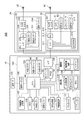
図4は、HMD100を構成する各部の構成を示すブロック図である。
制御装置10は、プログラムを実行してHMD100を制御するメインプロセッサー140を備える。メインプロセッサー140には、メモリー118及び不揮発性記憶部121が接続される。また、メインプロセッサー140には、入力装置としてトラックパッド14及び操作部110が接続される。また、メインプロセッサー140には、センサー類として、6軸センサー111、磁気センサー113、及び、GPS115が接続される。また、メインプロセッサー140には、通信部117、音声コーデック180、外部コネクター184、外部メモリーインターフェイス186、USBコネクター188、センサーハブ192、及び、FPGA194が接続される。これらは外部とのインターフェイスとして機能する。
FIG. 4 is a block diagram illustrating a configuration of each unit included in the
The
メインプロセッサー140は、制御装置10が内蔵するコントローラー基板120に実装される。コントローラー基板120には、メインプロセッサー140に加えて、メモリー118、不揮発性記憶部121等が実装されてもよい。本実施形態では、6軸センサー111、磁気センサー113、GPS115、通信部117、メモリー118、不揮発性記憶部121、音声コーデック180等がコントローラー基板120に実装される。また、外部コネクター184、外部メモリーインターフェイス186、USBコネクター188、センサーハブ192、FPGA194、及びインターフェイス196をコントローラー基板120に実装した構成であってもよい。
The
メモリー118は、メインプロセッサー140がプログラムを実行する場合に、実行されるプログラム、及び、処理されるデータを一時的に記憶するワークエリアを構成する。不揮発性記憶部121は、フラッシュメモリーやeMMC(Embedded Multi Media Card)で構成される。不揮発性記憶部121は、メインプロセッサー140が実行するプログラムや、メインプロセッサー140がプログラムを実行して処理する各種データを記憶する。
The
メインプロセッサー140は、トラックパッド14から入力される操作信号に基づいて、トラックパッド14の操作面に対する接触操作を検出し、操作位置を取得する。
操作部110は、ボタン11、タッチセンサー13、およびLED表示部17を含む。タッチセンサー13は、制御装置10が有するタッチ操作部へのタッチ操作を検出する。ボタン11の操作が行われた場合、及び、タッチセンサー13がタッチ操作を検出した場合、操作部110からメインプロセッサー140に対し、操作信号が出力される。
LED表示部17は、LEDインジケーター12(図1)が備えるLED、及び、このLEDを点灯させる駆動回路を含む。LED表示部17は、メインプロセッサー140の制御に従って、LEDを点灯、点滅、消灯させる。また、LED表示部17は、LEDが発光する輝度を制御してもよい。また、LED表示部17は、赤、青、緑の3色のLEDを備える構成であってもよく、この場合、各色のLEDの輝度を調整することによって任意の色でLEDインジケーター12を発光させてもよい。
The
The
The
6軸センサー111は、3軸加速度センサー、及び、3軸ジャイロ(角速度)センサーを備えるモーションセンサー(慣性センサー)である。6軸センサー111は、上記のセンサーがモジュール化されたIMU(Inertial Measurement Unit)を採用してもよい。
磁気センサー113は、例えば、3軸の地磁気センサーである。
GPS(Global Positioning System)115は、図示しないGPSアンテナを備え、GPS衛星から送信される無線信号を受信して、制御装置10の現在位置の座標を検出する。
6軸センサー111、磁気センサー113及びGPS115は、検出値を、予め指定されたサンプリング周期に従ってメインプロセッサー140に出力する。或いは、6軸センサー111、磁気センサー113及びGPS115は、メインプロセッサー140の要求に応じて、メインプロセッサー140により指定されたタイミングで、検出値をメインプロセッサー140に出力する。
The 6-
The
A GPS (Global Positioning System) 115 includes a GPS antenna (not shown), receives a radio signal transmitted from a GPS satellite, and detects the coordinates of the current position of the
The six-
通信部117は、外部の機器との間で無線通信を実行する。通信部117は、アンテナ、RF回路、ベースバンド回路、通信制御回路等を備えて構成され、或いはこれらが統合されたデバイスで構成される。通信部117は、例えば、Bluetooth(登録商標)、無線LAN(Wi−Fi(登録商標)を含む)等の規格に準拠した無線通信を行う。
音声インターフェイス182は、音声信号を入出力するインターフェイスである。本実施形態では、音声インターフェイス182は、接続ケーブル40に設けられたコネクター46(図1)を含む。音声コーデック180は、音声インターフェイス182に接続され、音声インターフェイス182を介して入出力される音声信号のエンコード/デコードを行う。また、音声コーデック180はアナログ音声信号からデジタル音声データへの変換を行うA/Dコンバーター、及び、その逆の変換を行うD/Aコンバーターを備えてもよい。例えば、本実施形態のHMD100は、音声を右イヤホン32及び左イヤホン34により出力し、マイク63で集音する。音声コーデック180は、メインプロセッサー140が出力するデジタル音声データをアナログ音声信号に変換して、音声インターフェイス182を介して出力する。また、音声コーデック180は、音声インターフェイス182に入力されるアナログ音声信号をデジタル音声データに変換してメインプロセッサー140に出力する。
The
The
外部コネクター184は、メインプロセッサー140と通信する外部の装置を接続するコネクターである。外部コネクター184は、例えば、外部の装置をメインプロセッサー140に接続して、メインプロセッサー140が実行するプログラムのデバッグや、HMD100の動作のログの収集を行う場合に、この外部の装置を接続するインターフェイスである。
外部メモリーインターフェイス186は、可搬型のメモリーデバイスを接続可能なインターフェイスであり、例えば、カード型記録媒体を装着してデータの読取が可能なメモリーカードスロットとインターフェイス回路とを含む。この場合のカード型記録媒体のサイズ、形状、規格は制限されず、適宜に変更可能である。
USB(Universal Serial Bus)コネクター188は、USB規格に準拠したコネクターとインターフェイス回路とを備え、USBメモリーデバイス、スマートフォン、コンピューター等を接続できる。USBコネクター188のサイズや形状、適合するUSB規格のバージョンは適宜に選択、変更可能である。
The
The
A USB (Universal Serial Bus)
また、HMD100は、バイブレーター19を備える。バイブレーター19は、モーター(図示略)、偏心した回転子(図示略)等を備え、メインプロセッサー140の制御に従って振動を発生する。HMD100は、例えば、操作部110に対する操作を検出した場合、HMD100の電源がオン/オフされる場合等に、所定の振動パターンでバイブレーター19により振動を発生する。
Further, the
センサーハブ192及びFPGA194は、インターフェイス(I/F)196を介して、画像表示部20を接続される。センサーハブ192は、画像表示部20が備える各種センサーの検出値を取得してメインプロセッサー140に出力する。また、FPGA194は、メインプロセッサー140と画像表示部20の各部との間で送受信するデータの処理、及び、インターフェイス196を介した伝送を実行する。
The
画像表示部20の右表示ユニット22及び左表示ユニット24は、それぞれ、制御装置10に接続される。図1に示すように、HMD100では左保持部23に接続ケーブル40が接続され、この接続ケーブル40に繋がる配線が画像表示部20内部に敷設され、右表示ユニット22と左表示ユニット24のそれぞれが制御装置10に接続される。
The
右表示ユニット22は、表示ユニット基板210を有する。表示ユニット基板210には、インターフェイス196に接続されるインターフェイス(I/F)211、インターフェイス211を介して制御装置10から入力されるデータを受信する受信部(Rx)213、及び、EEPROM215(記憶部)が実装される。
インターフェイス211は、受信部213、EEPROM215、温度センサー217、カメラ61、照度センサー65、及びLEDインジケーター67を、制御装置10に接続する。
The
The
EEPROM(Electrically Erasable Programmable Read-Only Memory)215は、各種のデータをメインプロセッサー140が読み取り可能に記憶する。EEPROM215は、例えば、画像表示部20が備えるOLEDユニット221、241の発光特性や表示特性に関するデータ、右表示ユニット22または左表示ユニット24が備えるセンサーの特性に関するデータなどを記憶する。具体的には、OLEDユニット221、241のガンマ補正に係るパラメーター、後述する温度センサー217、239の検出値を補償するデータ等を記憶する。これらのデータは、HMD100の工場出荷時の検査によって生成され、EEPROM215に書き込まれ、出荷後はメインプロセッサー140がEEPROM215のデータを利用して処理を行える。
An EEPROM (Electrically Erasable Programmable Read-Only Memory) 215 stores various data so that the
カメラ61は、インターフェイス211を介して入力される信号に従って撮像を実行し、撮像画像データ、或いは、撮像結果を示す信号を制御装置10に出力する。
照度センサー65は、図1に示すように、前部フレーム27の端部ERに設けられ、画像表示部20を装着する使用者の前方からの外光を受光するよう配置される。照度センサー65は、受光量(受光強度)に対応する検出値を出力する。
LEDインジケーター67は、図1に示すように、前部フレーム27の端部ERにおいてカメラ61の近傍に配置される。LEDインジケーター67は、カメラ61による撮像を実行中に点灯して、撮像中であることを報知する。
The
As shown in FIG. 1, the
As shown in FIG. 1, the
温度センサー217(温度検出部)は、温度を検出し、検出温度に対応する電圧値あるいは抵抗値を、検出値として出力する。温度センサー217は、OLEDパネル223(図3)の裏面側に実装される。温度センサー217は、例えばOLED駆動回路225と同一の基板に実装されてもよい。この構成により、温度センサー217は、主としてOLEDパネル223の温度を検出する。
The temperature sensor 217 (temperature detection unit) detects the temperature and outputs a voltage value or a resistance value corresponding to the detected temperature as a detection value. The
受信部213は、インターフェイス211を介してメインプロセッサー140が送信するデータを受信する。受信部213は、OLEDユニット221で表示する画像の画像データを受信した場合に、受信した画像データを、OLED駆動回路225(図2)に出力する。
The receiving
左表示ユニット24は、表示ユニット基板210を有する。表示ユニット基板210には、インターフェイス196に接続されるインターフェイス(I/F)231、インターフェイス231を介して制御装置10から入力されるデータを受信する受信部(Rx)233が実装される。また、表示ユニット基板210には、6軸センサー235、及び、磁気センサー237が実装される。
インターフェイス231は、受信部233、6軸センサー235、磁気センサー237、及び温度センサー239を、制御装置10に接続する。
The
The
6軸センサー235は、3軸加速度センサー、及び、3軸ジャイロ(角速度)センサーを備えるモーションセンサー(慣性センサー)である。6軸センサー235は、上記のセンサーがモジュール化されたIMU(Inertial Measurement Unit)を採用してもよい。
磁気センサー237は、例えば、3軸の地磁気センサーである。
The 6-
The
温度センサー239(温度検出部)は、温度を検出し、検出温度に対応する電圧値あるいは抵抗値を、検出値として出力する。温度センサー239は、OLEDパネル243(図3)の裏面側に実装される。温度センサー239は、例えばOLED駆動回路245と同一の基板に実装されてもよい。この構成により、温度センサー239は、主としてOLEDパネル243の温度を検出する。
また、温度センサー239が、OLEDパネル243或いはOLED駆動回路245に内蔵されてもよい。また、上記基板は半導体基板であってもよい。具体的には、OLEDパネル243が、Si−OLEDとして、OLED駆動回路245等とともに統合半導体チップ上の集積回路として実装される場合、この半導体チップに温度センサー239を実装してもよい。
The temperature sensor 239 (temperature detection unit) detects the temperature and outputs a voltage value or a resistance value corresponding to the detected temperature as a detection value. The
Further, the
右表示ユニット22が備えるカメラ61、照度センサー65、温度センサー217、及び、左表示ユニット24が備える6軸センサー235、磁気センサー237、温度センサー239は、センサーハブ192に接続される。センサーハブ192は、メインプロセッサー140の制御に従って各センサーのサンプリング周期の設定及び初期化を行う。センサーハブ192は、各センサーのサンプリング周期に合わせて、各センサーへの通電、制御データの送信、検出値の取得等を実行する。また、センサーハブ192は、予め設定されたタイミングで、右表示ユニット22及び左表示ユニット24が備える各センサーの検出値を、メインプロセッサー140に出力する。センサーハブ192は、各センサーの検出値を、メインプロセッサー140に対する出力のタイミングに合わせて一時的に保持する機能を備えてもよい。また、センサーハブ192は、各センサーの出力値の信号形式、或いはデータ形式の相違に対応し、統一されたデータ形式のデータに変換して、メインプロセッサー140に出力する機能を備えてもよい。
また、センサーハブ192は、メインプロセッサー140の制御に従ってLEDインジケーター67への通電を開始及び停止させ、カメラ61が撮像を開始及び終了するタイミングに合わせて、LEDインジケーター67を点灯または点滅させる。
The
The
制御装置10は、電源部130を備え、電源部130から供給される電力により動作する。電源部130は充電可能なバッテリー132、及び、バッテリー132の残容量の検出およびバッテリー132への充電の制御を行う電源制御回路134を備える。電源制御回路134はメインプロセッサー140に接続され、バッテリー132の残容量の検出値、或いは電圧の検出値をメインプロセッサー140に出力する。また、電源部130が供給する電力に基づき、制御装置10から画像表示部20に電力を供給してもよい。また、電源部130から制御装置10の各部及び画像表示部20への電力の供給状態を、メインプロセッサー140が制御可能な構成としてもよい。
The
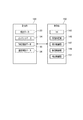
図5は、制御装置10の制御系を構成する記憶部122、及び制御部150の機能ブロック図である。図5に示す記憶部122は、不揮発性記憶部121(図4)により構成される論理的な記憶部であり、EEPROM215を含んでもよい。また、制御部150、及び、制御部150が有する各種の機能部は、メインプロセッサー140がプログラムを実行することによって、ソフトウェアとハードウェアとの協働により形成される。制御部150、及び制御部150を構成する各機能部は、例えば、メインプロセッサー140、メモリー118、及び不揮発性記憶部121により構成される。
FIG. 5 is a functional block diagram of the
制御部150は、記憶部122が記憶するデータを利用して各種処理を実行し、HMD100を制御する。
記憶部122は、制御部150が処理する各種のデータを記憶する。記憶部122は、設定データ123、コンテンツデータ124、輝度制御データ125、及び温度制御データ126を記憶する。設定データ123は、HMD100の動作に係る各種の設定値を含む。また、制御部150がHMD100を制御する際にパラメーター、行列式、演算式、LUT(LookUp Table)等を用いる場合、これらを設定データ123に含めてもよい。
コンテンツデータ124は、制御部150の制御によって画像表示部20が表示する画像や映像を含むコンテンツのデータであり、画像データ、或いは映像データを含む。また、コンテンツデータ124は、音声データを含んでもよい。また、コンテンツデータ124は複数の画像の画像データを含んでもよく、この場合、これら複数の画像は同時に画像表示部20に表示される画像に限定されない。
また、コンテンツデータ124は、コンテンツを画像表示部20により表示する際に、制御装置10によって使用者の操作を受け付けて、受け付けた操作に応じた処理を制御部150が実行する、双方向型のコンテンツであってもよい。この場合、コンテンツデータ124は、操作を受け付ける場合に表示するメニュー画面の画像データ、メニュー画面に含まれる項目に対応する処理等を定めるデータ等を含んでもよい。
The
The
The
The
輝度制御データ125は、制御部150が後述するようにOLEDパネル(パネル)223、243の輝度を調整する場合に参照するデータである。
温度制御データ126は、制御部150が、温度センサー217、239の検出温度に基づく動作を行う場合の閾値等を含む。制御部150は、例えば、温度制御データ126に含まれる閾値等と、温度センサー217、239の検出温度とを比較することにより、OLEDパネル223、243の輝度の調整等を行う。
The
The
制御部150は、オペレーティングシステム(OS)143、画像処理部145、表示制御部147、撮像制御部149、及び、検出制御部151の機能を有する。オペレーティングシステム143の機能は、記憶部122が記憶する制御プログラムの機能であり、その他の各部は、オペレーティングシステム143上で実行されるアプリケーションプログラムの機能である。
The
画像処理部145は、画像表示部20により表示する画像または映像の画像データに基づいて、右表示ユニット22及び左表示ユニット24に送信する信号を生成する。画像処理部145が生成する信号は、垂直同期信号、水平同期信号、クロック信号、アナログ画像信号等であってもよい。
また、画像処理部145は、必要に応じて、画像データの解像度を右表示ユニット22及び左表示ユニット24に適した解像度に変換する解像度変換処理を行ってもよい。また、画像処理部145は、画像データの輝度や彩度を調整する画像調整処理、3D画像データから2D画像データを作成し、或いは2D画像データから3D画像データを生成する2D/3D変換処理等を実行してもよい。画像処理部145は、これらの画像処理を実行した場合、処理後の画像データに基づき画像を表示するための信号を生成して、接続ケーブル40を介して画像表示部20に送信する。
The
Further, the
画像処理部145は、メインプロセッサー140がプログラムを実行して実現される構成のほか、メインプロセッサー140とは別のハードウェア(例えば、DSP(Digital Signal Processor))で構成してもよい。
The
表示制御部147は、右表示ユニット22及び左表示ユニット24を制御する制御信号を生成し、この制御信号により、右表示ユニット22及び左表示ユニット24のそれぞれによる画像光の生成及び射出を制御する。具体的には、表示制御部147は、OLED駆動回路225、245を制御して、OLEDパネル223、243による画像の表示を実行させる。表示制御部147は、画像処理部145が出力する信号に基づきOLED駆動回路225、245がOLEDパネル223、243に描画するタイミングの制御、OLEDパネル223、243の輝度の制御等を行う。
The
撮像制御部149は、カメラ61を制御して撮像を実行させ、撮像画像データを生成し、記憶部122に一時的に記憶する。また、カメラ61が撮像画像データを生成する回路を含むカメラユニットとして構成される場合、撮像制御部149は撮像画像データをカメラ61から取得して、記憶部122に一時的に記憶する。
The
検出制御部151は、温度センサー217、239の検出値を取得し、取得した検出値に基づき、画像表示部20の各部の温度の検出値、及び/または推定値を求める。検出制御部151は、例えば、OLEDパネル223、243の温度、右表示ユニット22及び左表示ユニット24の表面温度等の推定値を求める。また、温度センサー217、239の検出値と、検出制御部151が求める推定値との相関を示すデータ、演算式、係数等が、温度制御データ126に含まれてもよい。この場合、検出制御部151は、記憶部122の温度制御データ126を参照して、推定値を求める。
The
また、HMD100は、コンテンツの供給元となる種々の外部機器を接続するインターフェイス(図示略)を備えてもよい。例えば、USBインターフェイス、マイクロUSBインターフェイス、メモリーカード用インターフェイス等の有線接続に対応したインターフェイスであってもよく、無線通信インターフェイスで構成してもよい。この場合の外部機器は、HMD100に画像を供給する画像供給装置であり、パーソナルコンピューター(PC)、携帯電話端末、携帯型ゲーム機等が用いられる。この場合、HMD100は、これらの外部機器から入力されるコンテンツデータに基づく画像や音声を出力できる。
Further, the
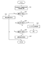
図6は、HMD100の動作を示すフローチャートである。
図6に示す動作は、制御部150の制御によって、画像表示部20に設けられた温度センサー217、239の検出温度に基づき、画像表示部20による表示を制御する動作を示す。また、図6のステップS15の処理について、図7〜図9を参照して詳細に説明する。
FIG. 6 is a flowchart showing the operation of the
The operation shown in FIG. 6 is an operation for controlling the display by the
以下の説明では、温度センサー217、239の検出温度を判定する閾値、或いは基準値として、TM1、TM2、TM3、TM4、及びTM5を使用する。これらのTM1〜TM5は、記憶部122に記憶される温度制御データ126に含めることができる。以下の説明では、TM1〜TM5は、温度センサー217、239の検出温度と比較可能な値とするが、温度センサー217、239の検出温度に対する判定に利用可能なデータであればよく、例えば、テーブルや演算式であってもよい。
In the following description, TM1, TM2, TM3, TM4, and TM5 are used as threshold values or reference values for determining the detected temperatures of the
制御部150は、検出制御部151により温度センサー217、239の検出値を取得する(ステップS11)。ステップS11で取得する値を検出温度Tとする。ステップS11で、検出制御部151は温度センサー217と温度センサー239の両方から検出値を取得するが、いずれか一方から取得してもよい。本実施形態では、検出制御部151は温度センサー217、239の両方の検出温度を取得して、温度センサー217の検出値と温度センサー239の検出値のいずれか高い方を温度Tとする。なお、検出制御部151は、温度センサー217の検出値および温度センサー239の検出値の2つの温度を含むデータを温度Tとしてもよい。また、温度センサー217の検出値と温度センサー239の検出値との平均値或いは演算処理で得られる値を温度Tとしてもよい。
The
制御部150は、温度センサー217、239の検出温度(温度T)をもとに、2つの動作モードを切り替えて実行する。これら2つの動作モードは、温度センサー217、239の検出値を取得する周期(サンプリング周期)が異なる。すなわち、制御部150は、サンプリング周期が低速(長周期)の通常モード、及び、サンプリング周期が高速(短周期)の監視モードを実行する。ステップS11で温度Tを取得するときの動作モードは通常モードであり、例えば、5秒〜10秒程度に設定された周期で温度Tを取得する。
通常モードから監視モードに移行する条件として、制御部150は閾値TM1を有する。検出制御部151は、ステップS11で取得した温度Tが、閾値TM1以上であるか否かを判定する(ステップS12)。温度Tが閾値TM1以上である場合(ステップS12;Yes)、検出制御部151は監視モードに移行して、温度Tを取得する周期を高速に設定する(ステップS13)。監視モードで温度Tを取得する周期は、例えば1秒程度である。
また、ステップS11で取得した温度Tが、閾値TM1より低い場合(ステップS12;No)、検出制御部151はステップS11に戻る。
The
As a condition for shifting from the normal mode to the monitoring mode, the
When the temperature T acquired in step S11 is lower than the threshold value TM1 (step S12; No), the
検出制御部151は、温度センサー217、239の検出温度を取得して、温度Tとする(ステップS14)。ステップS11と同様に、温度Tは、温度センサー217、239の検出温度のうち高い方の値であるが、平均値等であってもよい。
The
表示制御部147は、ステップS14で取得された温度Tに基づく温度制御を実行する(ステップS15)。表示制御部147が実行する温度制御は複数の処理を含み、本実施形態では、ユーザー保護制御、動作温度維持制御、及び、フリッカー抑制制御を含む。表示制御部147は、これらの制御をそれぞれ実行し、実行順序は制限されない。ここでは、表示制御部147が、ユーザー保護制御、動作温度維持制御、及び、フリッカー抑制制御のそれぞれを並列的に実行する場合を説明する。
The
図7は、HMD100の動作を示すフローチャートであり、図6のステップS15で実行される温度制御の一部を構成する、ユーザー保護制御を示すフローチャートである。
ユーザー保護制御は、右表示ユニット22及び左表示ユニット24が使用者に与える熱的影響を抑えるために、OLEDユニット221、241の発熱を抑制する制御である。右表示ユニット22及び左表示ユニット24は、画像表示部20の装着状態で使用者の側頭部に近接し、ときに当接することもある。OLEDパネル223、243の発熱により、右表示ユニット22及び左表示ユニット24の外装温度が高温となった場合、使用者の側頭部に熱を与えるため、使用者の違和感や不快感を招く等の懸念がある。
FIG. 7 is a flowchart showing the operation of the
User protection control is control which suppresses the heat_generation | fever of the
HMD100は、温度センサー217、239の検出温度である温度Tに基づき、右表示ユニット22及び左表示ユニット24の外装温度を抑える制御を行う。具体的には、表示制御部147が、温度Tの変化の履歴に基づき、右表示ユニット22及び左表示ユニット24の外装温度が制限温度を超える可能性を判定し、その可能性が高い場合にOLEDユニット221、241の輝度を低減させる。表示制御部147が判定を行う基準は、実験的に求められる温度センサー217、239の検出温度と右表示ユニット22及び左表示ユニット24の外装温度との相関等により、予め定められる。表示制御部147は、温度Tの履歴が条件を満たすか否かを判定する。当該条件としては、例えば、温度Tが、設定された閾値TM3を超える状態が、設定された時間以上継続する、といった条件が設定される。
The
図7において、表示制御部147は、ステップS14(図6)で取得した温度Tを、外装温度推定用の積算値に反映させる(ステップS31)。外装温度推定用の積算値は、時間、及び、温度Tの値に基づき加算される値である。ステップS31で、表示制御部147は、温度Tに基づいて外装温度推定用の積算値を加算する。温度Tが閾値TM3以上である場合にのみ加算してもよいし、閾値TM3より低温の場合に加算してもよい。
In FIG. 7, the
表示制御部147は、外装温度推定用の積算値が、予め設定された、輝度調整用の条件に該当するか否かを判定する(ステップS32)。外装温度推定用の積算値が輝度調整用の条件に該当する場合(ステップS32;Yes)、表示制御部147は、OLEDパネル223、243の表示輝度を低下させる輝度低減処理を実行する(ステップS33)。ステップS33の輝度低減処理で、表示制御部147は、OLEDパネル223、243の両方の輝度を低下させる。このため、使用者が画像表示部20において視認する画像光の輝度が、左右両方で低下するので、違和感を与えずに輝度を調整できる。また、ステップS33の1回の処理で輝度を低下させる低下幅は、使用者の違和感を招かない程度の幅に、予め設定される。
The
外装温度推定用の積算値が輝度調整用の条件に該当しない場合(ステップS32;No)、表示制御部147は、外装温度推定用の積算値が停止条件に該当するか否かを判定する(ステップS34)。停止条件は、HMD100を停止させる条件であり、右表示ユニット22または左表示ユニット24の外装温度が、よりシビアな状態になっていることを示す条件である。表示制御部147は、外装温度推定用の積算値が停止条件に該当する場合(ステップS34;Yes)、HMD100を停止させるシャットダウンシーケンスを実行して(ステップS35)、本処理を終了する。ステップS35では、OLEDユニット221、241のダメージを回避するため、HMD100を強制的にシャットダウンするが、例えば、画像表示部20への通電を強制的に停止してもよい。
When the integrated value for exterior temperature estimation does not correspond to the condition for brightness adjustment (step S32; No), the
ステップS33〜S35の動作は言い換えれば、表示制御部147が、右表示ユニット22または左表示ユニット24の外装温度が高温の場合に輝度低減処理を実行し、より速やかに外装温度を低下させる必要がある場合にシャットダウン処理を行うといえる。
In other words, the operations of steps S33 to S35 require the
外装温度推定用の積算値が停止条件に該当しない場合(ステップS34;No)、表示制御部147は、外装温度推定用の積算値が輝度低減の解除条件に該当するか否かを判定する(ステップS36)。解除条件は、ステップS33で実行した輝度低減処理を解除して、OLEDパネル223、243の輝度を、ステップS33の処理前の状態に戻す条件である。すなわち、右表示ユニット22及び左表示ユニット24の外装温度が十分に低いといえる状態に対応する条件である。
When the integrated value for exterior temperature estimation does not correspond to the stop condition (step S34; No), the
外装温度推定用の積算値が解除条件に該当する場合(ステップS36;Yes)、表示制御部147は、ステップS33で実行した輝度低減処理を解除し、OLEDパネル223、243の輝度を調整し(ステップS37)、図6の動作に戻る。
また、外装温度推定用の積算値が解除条件に該当しない場合(ステップS36;No)、表示制御部147は、図6の動作に戻る。
When the integrated value for exterior temperature estimation corresponds to the cancellation condition (step S36; Yes), the
If the integrated value for exterior temperature estimation does not correspond to the release condition (step S36; No), the
図7に示すユーザー保護制御で使用する外装温度推定用の積算値は、例えば、メモリー118(図4)に保持され、表示制御部147の機能により加算、更新、参照される。また、ユーザー保護制御で使用される調整条件、停止条件、及び解除条件は、記憶部122に記憶される輝度制御データ125に含めてもよい。
The integrated value for exterior temperature estimation used in the user protection control shown in FIG. 7 is held in, for example, the memory 118 (FIG. 4), and is added, updated, and referenced by the function of the
図8は、HMD100の動作を示すフローチャートであり、図6のステップS15で実行される温度制御の一部を構成する、動作温度維持制御を示すフローチャートである。
動作温度維持制御は、OLEDユニット221、241、或いはOLEDパネル223、243の温度が、製造事業者が定める動作保証温度に基づき定められる動作温度範囲を逸脱しないようにする制御である。
FIG. 8 is a flowchart showing the operation of the
The operation temperature maintenance control is control that prevents the temperature of the
HMD100は、温度センサー217、239の検出温度である温度Tに基づき、OLEDパネル223、243及びOLED駆動回路225、245の温度を抑える制御を行う。具体的には、表示制御部147が、温度Tの変化の履歴に基づき、OLEDパネル223、243及びOLED駆動回路225、245の温度が動作温度範囲を逸脱する可能性を判定し、その可能性が高い場合にOLEDユニット221、241の輝度を低減させる。表示制御部147が判定を行う基準は、実験的に求められる温度センサー217、239の検出温度とOLEDパネル223、243及びOLED駆動回路225、245の温度との相関等により、予め定められる。表示制御部147は、温度Tの履歴が条件を満たすか否かを判定する。当該条件としては、例えば、温度Tが、設定された閾値TM4を超える状態が、設定された時間以上継続する、といった条件が設定される。
The
図8において、表示制御部147は、ステップS14(図6)で取得した温度Tを、回路保護用の積算値に反映させる(ステップS41)。回路保護用の積算値は、時間、及び、温度Tの値に基づき加算される値である。ステップS41で、表示制御部147は、温度Tに基づいて回路保護用の積算値を加算する。温度Tが閾値TM4以上である場合にのみ加算してもよいし、閾値TM4より低温の場合に加算してもよい。
In FIG. 8, the
表示制御部147は、回路保護用の積算値が、予め設定された、輝度調整用の条件に該当するか否かを判定する(ステップS42)。回路保護用の積算値が輝度調整用の条件に該当する場合(ステップS42;Yes)、表示制御部147は、OLEDパネル223、243の表示輝度を低下させる輝度低減処理を実行する(ステップS43)。ステップS43の輝度低減処理で、表示制御部147は、OLEDパネル223、243の両方の輝度を低下させる。このため、使用者が画像表示部20において視認する画像光の輝度が、左右両方で低下するので、違和感を与えずに輝度を調整できる。また、ステップS43の1回の処理で輝度を低下させる低下幅は、使用者の違和感を招かない程度の幅に、予め設定される。
The
回路保護用の積算値が輝度調整用の条件に該当しない場合(ステップS42;No)、表示制御部147は、回路保護用の積算値が停止条件に該当するか否かを判定する(ステップS44)。停止条件は、HMD100を停止させる条件であり、OLEDパネル223、243またはOLED駆動回路225、245の温度が、よりシビアな状態になっていることを示す条件である。表示制御部147は、回路保護用の積算値が停止条件に該当する場合(ステップS44;Yes)、HMD100を停止させるシャットダウンシーケンスを実行して(ステップS45)、本処理を終了する。ステップS45では、OLEDユニット221、241のダメージを回避するため、HMD100を強制的にシャットダウンするが、例えば、画像表示部20への通電を強制的に停止してもよい。
When the integrated value for circuit protection does not correspond to the condition for brightness adjustment (step S42; No), the
回路保護用の積算値が停止条件に該当しない場合(ステップS44;No)、表示制御部147は、回路保護用の積算値が輝度低減の解除条件に該当するか否かを判定する(ステップS46)。解除条件は、ステップS43で実行した輝度低減処理を解除して、OLEDパネル223、243の輝度を、ステップS43の処理前の状態に戻す条件である。すなわち、OLEDパネル223、243またはOLED駆動回路225、245の温度が、動作温度範囲の上限よりも十分に低い場合に対応する条件である。
When the integrated value for circuit protection does not correspond to the stop condition (step S44; No), the
回路保護用の積算値が解除条件に該当する場合(ステップS46;Yes)、表示制御部147は、ステップS43で実行した輝度低減処理を解除し、OLEDパネル223、243の輝度を調整し(ステップS47)、図6の動作に戻る。
また、回路保護用の積算値が解除条件に該当しない場合(ステップS46;No)、表示制御部147は、図6の動作に戻る。
When the integrated value for circuit protection meets the cancellation condition (step S46; Yes), the
If the integrated value for circuit protection does not correspond to the release condition (step S46; No), the
図8に示す回路保護用の積算値は、例えば、メモリー118(図4)に保持され、表示制御部147の機能により加算、更新、参照される。また、動作温度維持制御で使用される調整条件、停止条件、及び解除条件は、記憶部122に記憶される輝度制御データ125に含めてもよい。
The integrated value for circuit protection shown in FIG. 8 is held in, for example, the memory 118 (FIG. 4), and is added, updated, or referred to by the function of the
図9は、HMD100の動作を示すフローチャートであり、図6のステップS15で実行される温度制御の一部を構成する、フリッカー抑制制御を示すフローチャートである。フリッカー抑制制御は、OLEDパネル223、243の温度を、フリッカーを発現する可能性が高い温度よりも低温に維持することで、表示品位を保つための制御である。
FIG. 9 is a flowchart illustrating the operation of the
表示制御部147は、ステップS14(図4)で取得した温度Tが、フリッカー閾値TM5より高いか否かを判定する(ステップS51)。フリッカー閾値TM5は、OLEDパネル223、243の温度の上昇により表示画像のフリッカー(ちらつき)が発生することに鑑み、フリッカーを抑制できる目安として設定される閾値である。
The
ステップS11で取得した温度Tが閾値TM5より高い場合(ステップS51;Yes)、表示制御部147は、HMD100の動作状態において自動調光がONになっているか否かを判定する(ステップS52)。自動調光は、OLEDユニット221、241の輝度を照度センサー65の検出値に基づき自動的に調整する機能オプションである。自動調光がONの場合、OLEDパネル223、243の輝度は、照度センサー65が検出する外光の光量と比較して、右表示ユニット22及び左表示ユニット24の表示画像の視認性を確保できる最低限の輝度に調整される。つまり、右表示ユニット22及び左表示ユニット24の表示画像を視認できる範囲において最低限度の輝度に設定される。このため、自動調光をONにすると、OLEDパネル223、243が発熱しにくくなり、温度上昇が抑制される。さらに、自動調光がONになると、右表示ユニット22におけるOLEDパネル223の輝度と左表示ユニット24におけるOLEDパネル243の輝度とが、対応する輝度に設定される。より詳細には、OLEDパネル223、243のそれぞれの輝度が、より輝度が低い側に合わせて設定される。これに対し、自動調光がOFFの場合、OLEDパネル223、243の輝度はそれぞれ個別に設定可能であり、外光の光量とも無関係に設定できるので、高輝度になりやすい。
When the temperature T acquired in step S11 is higher than the threshold value TM5 (step S51; Yes), the
表示制御部147は、自動調光がオフである場合(ステップS52;No)、自動調光をONに設定して(ステップS53)、図6の動作に戻る。また、自動調光が既にONである場合(ステップS52;Yes)、表示制御部147は、OLEDパネル223、243の輝度を、現在の輝度よりも1段階低く設定して(ステップS54)、図6の動作に戻る。また、ステップS11で取得した温度Tがフリッカー閾値TM5以下の場合(ステップS51;No)、表示制御部147は、図6の動作に戻る。
When the automatic light control is off (step S52; No), the
図6に戻り、表示制御部147は、ステップS15で実行した温度制御のいずれかにおいて、OLEDパネル223、243の輝度を調整する動作を実行したか否かを判定する(ステップS16)。ステップS16の判定は、ステップS15が完了してからフロー制御により実行してもよいが、ステップS15の温度制御で輝度の調整を行った場合に、割込によりステップS16の判定を実行してもよい。本実施形態のステップS16では、OLEDパネル223、243の輝度の変更を伴う何らかの処理を表示制御部147が実行したか否かを判定し、処理の内容は制限されない。
Returning to FIG. 6, the
図7のステップS33、S37、図8のステップS43、S47、図9のステップS53、S54のいずれかを実行した場合、ステップS16では、OLEDパネル223、243の輝度を調整したと判定される。OLEDパネル223、243の輝度を調整したと判定された場合(ステップS16;Yes)、表示制御部147は、OLEDユニット221、241のガンマ補正を実行する(ステップS17)。ステップS17で、表示制御部147は、検出制御部151により温度Tを新たに取得してもよい。この場合、HMD100は、EEPROM215に、OLEDパネル223、243の温度毎のガンマ補正用のパラメーターを記憶する。表示制御部147は、ステップS17で、OLEDパネル223、243の温度に対応するガンマ補正用のパラメーターを、EEPROM215から読み出して適用することにより、OLEDパネル223、243のガンマ補正を行う。これにより、OLEDパネル223、243の温度による色味の変化を適切に補正して、高い表示品位で画像を表示できる。ステップS17のガンマ補正処理で、表示制御部147は、温度センサー217の検出温度に基づきガンマ補正用のパラメーターを用いてOLEDパネル223のガンマ補正を行ってもよい。また、温度センサー239の検出温度に対応するガンマ補正用のパラメーターを用いて、OLEDパネル243のガンマ補正を行ってもよい。また、制御部150は、画像表示部20により表示を行う間、常時ガンマ補正を行うよう構成してもよい。この場合、制御部150は、ガンマ補正に用いるテーブルまたはパラメーターを、温度センサー239の検出温度に対応するガンマ補正用のテーブルまたはパラメーターで更新すればよい。
When one of steps S33 and S37 in FIG. 7, steps S43 and S47 in FIG. 8, and steps S53 and S54 in FIG. 9 is executed, it is determined in step S16 that the luminance of the
続いて、制御部150は、ステップS14で取得した温度T、または、ステップS14より後のタイミングで取得した温度Tが、監視モードから通常モードへの移行条件を満たすか否かを判定する(ステップS18)。通常モードへの移行条件は、例えば、ステップS14またはステップS14より後のタイミングで取得した温度Tと比較される閾値TM2である。通常モード移行条件を満たさないと判定した場合(ステップS18;No)、制御部150は、ステップS14に戻る。
また、通常モード移行条件を満たすと判定した場合(ステップS18;Yes)、制御部150は、動作モードを監視モードから通常モードに移行して、温度センサー217、239の検出値を取得する周期を低速に設定する(ステップS19)。制御部150は表示を終了する終了条件が成立したか否かを判定する(ステップS20)。終了条件は、操作部110やトラックパッド14により表示終了の指示が入力されること、電源部130のバッテリーの残量が不足すること、コンテンツデータ124の再生表示が終了すること、等である。終了条件が成立していない場合(ステップS20;No)、制御部150はステップS11に戻り、終了条件が成立した場合は(ステップS20;Yes)、本処理を終了する。
Subsequently, the
When it is determined that the normal mode transition condition is satisfied (step S18; Yes), the
ステップS33、S43、S54でOLEDパネル223、243の輝度を低下させる処理は、OLEDパネル223、243の全体の階調、或いは輝度を低下させてもよい。また、OLEDパネル223、243を構成する画素のうち、発光する画素を制限し、一部の画素を発光させる制御を行ってもよい。この場合、発光する画素数が減ることによってOLEDパネル223、243の温度を低下させ、或いは温度上昇を抑制させることができる。また、発光する画素により、OLEDパネル223、243の全ての画素を用いる場合よりも狭い範囲ではあるが、表示を行うことが可能である。
The process of reducing the brightness of the
以上説明したように、使用者が装着して使用するHMD100は、映像光を生じさせる右表示ユニット22、及び、左表示ユニット24を有する。また、HMD100は、右表示ユニット22が発する光に基づき使用者の右眼に画像を視認させ、左表示ユニット24が発する光に基づき使用者の左眼に画像を視認させる画像表示部20を備える。また、右表示ユニット22及び左表示ユニット24のそれぞれの温度を検出する温度センサー217、239を備える。また、温度センサー217、239により検出した温度に基づき右表示ユニット22及び左表示ユニット24の少なくともいずれかの輝度を制御する制御部150と、を備える。この構成により、右表示ユニット22または左表示ユニット24の温度変化に対応して、右表示ユニット22または左表示ユニット24が出力する映像光の輝度を調整し、右表示ユニット22及び左表示ユニット24の動作温度を適正な範囲内に維持できる。
As described above, the
また、制御部150は、右表示ユニット22及び左表示ユニット24の温度に基づき、右表示ユニット22及び左表示ユニット24が発する映像光の輝度を、右表示ユニット22及び左表示ユニット24のうち低輝度で発光する側の輝度に合わせる制御を行う。この構成により、表示画像の視認性を極端に変化させることなく、右表示ユニット22及び左表示ユニット24の温度上昇に対応して輝度を調整し、動作温度を適正な範囲内に維持できる。
Further, the
また、制御部150は、右表示ユニット22及び左表示ユニット24のいずれかの温度が閾値以上となった場合に、右表示ユニット22及び左表示ユニット24の輝度を、低輝度で発光する側の輝度に合わせる制御を行う。これにより、右表示ユニット22及び左表示ユニット24のいずれかの温度の上昇に対応して、表示画像の視認性を極端に変化させることなく、輝度を低下させ、動作温度を適正な範囲内に維持できる。
In addition, when the temperature of either the
また、制御部150は、右表示ユニット22及び左表示ユニット24の温度に基づき、右表示ユニット22及び左表示ユニット24の輝度を、画像表示部20の外光の照度に対応する輝度に合わせる制御を行う。すなわち、照度センサー65の検出値に対応してOLEDパネル223、243の輝度を調整する、自動調光を実行する。これにより、右表示ユニット22及び左表示ユニット24の輝度を、HMD100の環境光の明るさに合わせて調整し、表示画像の視認性を極端に低下させることなく、輝度を調整できる。
In addition, the
また、画像表示部20は、右表示ユニット22が発する光及び左表示ユニット24が発する光に基づく画像を使用者に視認させ、外景を透過して使用者に視認させる構成を有する。制御部150は、右表示ユニット22及び左表示ユニット24の輝度を、画像表示部20を透過する外光の照度に対応する輝度に合わせる制御を行う。これにより、使用者が、画像表示部20を透過する外光と右表示ユニット22及び左表示ユニット24が発する光とを重ねて視認する構成において、外光の照度に合わせて右表示ユニット22及び左表示ユニット24の輝度を調整する。この構成により、外光により視認される外景および表示画像の両方の視認性を確保し、右表示ユニット22及び左表示ユニット24の輝度を調整できる。
In addition, the
また、画像表示部20は、右表示ユニット22が発する光を使用者の右眼に導く右導光板26、及び、左表示ユニット24が発する光を使用者の左眼に導く左導光板28を備える。これにより、使用者の左右の眼に視認される画像の輝度のバランスを適正に保ちながら、右表示ユニット22、及び左表示ユニット24の温度上昇に対応して輝度を調整できる。
Further, the
また、右表示ユニット22、及び左表示ユニット24は、それぞれ使用者の頭部の側方に位置する。これら使用者の頭部の側方に位置する右表示ユニット22、及び左表示ユニット24の温度上昇に対応して、輝度を調整し、動作温度を適正な範囲内に維持できる。
Moreover, the
また、制御部150は、右表示ユニット22または左表示ユニット24の少なくともいずれかが、使用者の身体への影響に基づき定められた閾値以上となった場合に、右表示ユニット22及び左表示ユニット24の少なくともいずれかの輝度を低下させる。
この構成により、使用者の頭部の側方に位置する右表示ユニット22、及び左表示ユニット24の温度が、使用者の身体への影響が懸念される温度になる前に輝度を調整し、温度上昇に対処できる。
The
With this configuration, the brightness of the
また、右表示ユニット22及び左表示ユニット24は、発光体を実装したOLEDパネル223、243を備え、温度センサー217、239は発光体の裏側でOLEDパネル223、243に接して配置されるので、発光に伴う度変化を的確に検出できる。
Further, the
また、右表示ユニット22及び左表示ユニット24は、それぞれ、複数の色光を含む画像光を出力する映像素子としてのOLEDパネル223、243と、OLEDパネル223、243を駆動するOLED駆動回路225、245とを備える。温度センサー217、239はOLED駆動回路225、245に実装されてOLEDパネル223、243の温度を検出する。このため、OLEDパネル223、243を駆動して表示を行い、温度センサー217、239で温度を検出する構成を、コンパクトな構成で実現できる。
The
また、OLEDパネル223、243が発する画像光のガンマ値を補正する補正パラメーターを、OLEDパネル223、243の温度ごとに記憶するEEPROM215を備える。制御部150は、温度センサー217、239により検出した温度に基づき右表示ユニット22及び左表示ユニット24の少なくともいずれかの輝度を制御する。そして、温度センサー217、239により検出した温度に対応する補正パラメーターを用いてOLEDパネル223、243のガンマ補正を実行する。このため、OLEDパネル223、243が発する光の色を補正することにより、表示画像の品位を高品位に維持できる。
In addition, an
また、上記実施形態では、温度センサー217、239が、OLED駆動回路225、245とともに実装される構成を例示した。本発明はこれに限定されず、例えば、OLEDユニット221、241とは別体として、温度センサー217、239を配置してもよい。
Moreover, in the said embodiment, the
さらに、制御部150は、6軸センサー235及び磁気センサー237または、これらを構成するIMUが温度検出機能を有する場合において、6軸センサー235及び磁気センサー237を用いて温度検出を行ってもよい。この場合、制御部150は、検出制御部151によって温度センサー217、239から取得する検出値と、6軸センサー235及び磁気センサー237により検出される温度とを比較してもよい。この比較により、制御部150は、温度センサー217、239の動作が正常であるか否かを判定してもよい。このセンサーは、例えば、左表示ユニット24のケースを構成するパネル裏面の基板に実装される。制御部150は、温度センサー217、239から取得する検出値に加え、6軸センサー235及び磁気センサー237により検出される温度を、図7の処理で使用してもよい。この場合、温度センサー217、239に限らず、6軸センサー235及び磁気センサー237により検出される温度が、使用者の身体に影響する可能性のある温度となった場合に、温度を低下させる制御を行える。また、複数の温度センサーを用いることで、いずれかの温度センサーの故障や異常が発生した場合に、これを検出できるという利点がある。また、左表示ユニット24の内部において異なる位置にあるセンサーを用いることで、左表示ユニット24の内部の温度差に対応する制御を行えるという利点がある。
Further, the
上記実施形態においては、右表示ユニット22及び左表示ユニット24は、OLEDパネル223、243によって画像光を発し、この画像光を使用者の眼に導くことで画像を視認させる構成を例示した。ここで、右表示ユニット22及び左表示ユニット24を映像素子と呼んでもよいし、OLEDパネル223、243を映像素子としてもよい。
本発明はこれに限定されず、OLEDパネル223、243をバックライトとして利用し、このバックライトが発する光を変調することによって、画像を表示する構成であってもよい。すなわち、映像素子が、バックライトと、バックライトが発する光を変調して映像光を生成する変調部とを有する構成であってもよい。この例を図10に示す。
In the above embodiment, the
The present invention is not limited to this, and an
[変形例]
図10は、上記実施形態の変形例としての光学系の構成を示す図である。
図10の構成では、使用者の右眼REに対応してOLEDユニット221aが設けられ、左眼LEに対応してOLEDユニット241aが設けられる。OLEDユニット221aは、白色で発光するOLEDパネル223aと、OLEDパネル223aを駆動して発光させるOLED駆動回路225とを備える。また、OLEDパネル223aと右光学系251との間には、変調素子227(変調装置)が配置される。変調素子227は、例えば、透過型液晶パネルで構成され、OLEDパネル223aが発する光を変調して画像光Lを生成する。変調素子227を透過して変調された画像光Lは、右導光板26により、右眼REに導かれる。
[Modification]
FIG. 10 is a diagram showing a configuration of an optical system as a modification of the embodiment.
In the configuration of FIG. 10, an
また、OLEDユニット241aは、白色で発光するOLEDパネル243aと、OLEDパネル243aを駆動して発光させるOLED駆動回路245とを備える。OLEDパネル243aと左光学系252との間には、変調素子247(変調装置)が配置される。変調素子247は、例えば、透過型液晶パネルで構成され、OLEDパネル243aが発する光を変調して画像光Lを生成する。変調素子247を透過して変調された画像光Lは、左導光板28により、左眼LEに導かれる。
The
変調素子227、247は、図示しない液晶ドライバー回路に接続される。この液晶ドライバー回路(変調装置駆動部)は、例えば変調素子227、247の近傍に配置される基板(図示略)に実装される。そして、この基板に、温度センサー217、239を配置できる。
The
この構成によれば、右表示ユニット22及び左表示ユニット24は、それぞれ、光源部としてのOLEDパネル223a、243aと、光源部が発する光を変調して複数の色光を含む画像光を出力する変調素子227、247とを備える映像素子として構成される。また、変調素子227、247を駆動する液晶ドライバー回路を備え、温度センサー217、239は液晶ドライバー回路とともに実装される。この構成により、OLEDパネル223a、243aを用いる光源部が発する光を変調して画像光を出力する構成において、光源及び変調装置の温度の変化を的確に検出できる。
According to this configuration, each of the
OLEDパネル223a、243aが発する光を変調する変調装置は、透過型液晶パネルで構成される構成に限定されず、反射型液晶パネルを用いてもよいし、デジタル・マイクロミラー・デバイス等を用いてもよい。
The modulation device that modulates the light emitted from the
なお、この発明は上記実施形態及び変形例の構成に限られるものではなく、その要旨を逸脱しない範囲において種々の態様において実施することが可能である。
上記実施形態において、使用者が表示部を透過して外景を視認する構成は、右導光板26及び左導光板28が外光を透過する構成に限定されない。例えば外景を視認できない状態で画像を表示する表示装置にも適用可能である。具体的には、カメラ61の撮像画像、この撮像画像に基づき生成される画像やCG、予め記憶された映像データや外部から入力される映像データに基づく映像等を表示する表示装置に、本発明を適用できる。この種の表示装置としては、外景を視認できない、いわゆるクローズ型の表示装置を含むことができる。また、上記実施形態で説明したように実空間に重ねて画像を表示するAR表示や、撮像した実空間の画像と仮想画像とを組み合わせるMR(Mixed Reality)表示、或いは仮想画像を表示するVR(Virtual Reality)表示といった処理を行わない表示装置にも適用できる。例えば、外部から入力される映像データまたはアナログ映像信号を表示する表示装置も、本発明の適用対象として勿論含まれる。
In addition, this invention is not restricted to the structure of the said embodiment and modification, It can implement in a various aspect in the range which does not deviate from the summary.
In the above embodiment, the configuration in which the user visually recognizes the outside scene through the display unit is not limited to the configuration in which the right
また、例えば、画像表示部20に代えて、例えば帽子のように装着する画像表示部等の他の方式の画像表示部を採用してもよく、使用者の左眼に対応して画像を表示する表示部と、使用者の右眼に対応して画像を表示する表示部とを備えていればよい。また、本発明の表示装置は、例えば、自動車や飛行機等の車両に搭載されるヘッドマウントディスプレイとして構成されてもよい。また、例えば、ヘルメット等の身体防護具に内蔵されたヘッドマウントディスプレイとして構成されてもよい。この場合、使用者の身体に対する位置を位置決めする部分、及び、当該部分に対し位置決めされる部分を装着部とすることができる。
Further, for example, instead of the
さらに、上記実施形態では、画像表示部20と制御装置10とが分離され、接続ケーブル40を介して接続された構成を例に挙げて説明したが、制御装置10と画像表示部20とが一体に構成され、使用者の頭部に装着される構成とすることも可能である。
また、制御装置10として、ノート型コンピューター、タブレット型コンピューター又はデスクトップ型コンピューターを用いてもよい。また、制御装置10として、ゲーム機や携帯型電話機やスマートフォンや携帯型メディアプレーヤーを含む携帯型電子機器、その他の専用機器等を用いてもよい。また、制御装置10が画像表示部20と分離して構成され、制御装置10と画像表示部20との間で無線通信により各種信号を送受信する構成としてもよい。
Further, in the above embodiment, the
As the
また、画像光を使用者の眼に導く光学系として、右導光板26及び左導光板28の一部に、ハーフミラー261、281により虚像が形成される構成を例示した。本発明はこれに限定されず、右導光板26及び左導光板28の全面または大部分を占める面積を有する表示領域に、画像を表示する構成としてもよい。この場合、画像の表示位置を変化させる動作において、画像を縮小する処理を含めてもよい。
さらに、本発明の光学素子は、ハーフミラー261、281を有する右導光板26、左導光板28に限定されず、画像光を使用者の眼に入射させる光学部品であればよく、具体的には、回折格子、プリズム、ホログラフィー表示部を用いてもよい。
In addition, as an optical system that guides image light to the user's eyes, a configuration in which virtual images are formed by the half mirrors 261 and 281 on a part of the right
Furthermore, the optical element of the present invention is not limited to the right
また、図4等に示した各機能ブロックのうち少なくとも一部は、ハードウェアで実現してもよいし、ハードウェアとソフトウェアの協働により実現される構成としてもよく、図に示した通りに独立したハードウェア資源を配置する構成に限定されない。また、制御部150が実行するプログラムは、不揮発性記憶部121または制御装置10内の他の記憶装置(図示略)に記憶されてもよいし、外部の装置に記憶されたプログラムを通信部117や外部コネクター184を介して取得して実行する構成としてもよい。また、制御装置10に形成された構成のうち、操作部110が使用者インターフェイス(UI)として形成されてもよい。また、制御装置10に形成された構成が重複して画像表示部20に形成されていてもよい。例えば、メインプロセッサー140と同様のプロセッサーが画像表示部20に配置されてもよいし、制御装置10が備えるメインプロセッサー140と画像表示部20のプロセッサーとが別々に分けられた機能を実行する構成としてもよい。
Also, at least a part of each functional block shown in FIG. 4 or the like may be realized by hardware, or may be realized by cooperation of hardware and software, as shown in the figure. It is not limited to a configuration in which independent hardware resources are arranged. The program executed by the
10…制御装置、18…電源スイッチ、20…画像表示部(表示部)、21…右保持部、22…右表示ユニット(第1映像素子)、23…左保持部、24…左表示ユニット(第2映像素子)、26…右導光板、27…前部フレーム、28…左導光板、30…ヘッドセット、40…接続ケーブル、61…カメラ、63…マイク、65…照度センサー、67…LEDインジケーター、100…HMD(表示装置)、110…操作部、111…6軸センサー、113…磁気センサー、115…GPS、117…通信部、118…メモリー、119…バイブレーター、120…コントローラー基板、121…不揮発性記憶部、122…記憶部、123…設定データ、124…コンテンツデータ、125…輝度制御データ、126…温度制御データ、130…電源部、132…バッテリー、134…電源制御回路、140…メインプロセッサー、143…オペレーティングシステム、145…画像処理部、149…撮像制御部、150…制御部、151…検出制御部、180…音声コーデック、182…音声インターフェイス、184…外部コネクター、186…外部メモリーインターフェイス、188…USBコネクター、192…センサーハブ、194…FPGA、196…インターフェイス、211…インターフェイス、213…受信部、215…EEPROM(記憶部)、217…温度センサー(温度検出部)、221…OLEDユニット、223…OLEDパネル(パネル)、225…OLED駆動回路(駆動部)、231…インターフェイス、233…受信部、235…6軸センサー、237…磁気センサー、239…温度センサー(温度検出部)、241…OLEDユニット、243…OLEDパネル(パネル)、245…OLED駆動回路(駆動部)、251…右光学系、252…左光学系、261…ハーフミラー、281…ハーフミラー。
DESCRIPTION OF
Claims (14)
映像光を生じさせる第1映像素子、及び、第2映像素子と、
前記第1映像素子により生じる映像光に基づき前記使用者の右眼に画像を視認させ、前記第2映像素子により生じる映像光に基づき前記使用者の左眼に画像を視認させる表示部と、
前記第1映像素子及び前記第2映像素子のそれぞれの温度を検出する温度検出部と、
前記温度検出部により検出した温度に基づき前記第1映像素子及び前記第2映像素子の少なくともいずれかが生じさせる映像光の輝度を制御する制御部と、
を備えることを特徴とする表示装置。 A display device worn by a user and used.
A first image element and a second image element for generating image light;
A display unit that causes the user's right eye to visually recognize an image based on video light generated by the first video element, and causes the user's left eye to visually recognize an image based on video light generated from the second video element;
A temperature detector for detecting the temperature of each of the first video element and the second video element;
A control unit for controlling luminance of image light generated by at least one of the first image element and the second image element based on the temperature detected by the temperature detection unit;
A display device comprising:
を特徴とする請求項1記載の表示装置。 The controller controls the brightness of the video light generated by the first video element and the second video element based on the temperatures of the first video element and the second video element, and controls the first video element and the second video element. Control to match the brightness of the low brightness side of the image element,
The display device according to claim 1.
を特徴とする請求項2記載の表示装置。 The control unit, when the temperature of either the first video element and the second video element is equal to or higher than a threshold, the brightness of the video light generated by the first video element and the second video element, Performing control to match the low luminance side of the first video element and the second video element;
The display device according to claim 2.
を特徴とする請求項2または3記載の表示装置。 The control unit converts the luminance of the video light generated by the first video device and the second video device to the illuminance of outside light of the display unit based on the temperatures of the first video device and the second video device. Control to match the corresponding brightness,
The display device according to claim 2, wherein:
前記制御部は、前記第1映像素子及び前記第2映像素子が生じさせる映像光の輝度を、前記表示部を透過する外光の照度に対応する輝度に合わせる制御を行うこと、
を特徴とする請求項4記載の表示装置。 The display unit has a configuration in which the user visually recognizes an image based on the video light generated by the first video element and the video light generated by the second video element, and allows the user to visually recognize the image through an outside scene. ,
The control unit performs control to adjust the luminance of the video light generated by the first video element and the second video element to a luminance corresponding to the illuminance of external light transmitted through the display unit;
The display device according to claim 4.
を特徴とする請求項1から5のいずれかに記載の表示装置。 The display unit includes an optical unit that guides image light generated by the first image element to the right eye of the user and guides image light generated by the second image element to the left eye of the user;
The display device according to claim 1, wherein:
を特徴とする請求項1から6のいずれかに記載の表示装置。 Each of the first image element and the second image element is located on a side of the user's head;
The display device according to claim 1, wherein:
を特徴とする請求項7記載の表示装置。 The control unit, when at least one of the first video device and the second video device is equal to or higher than a threshold value determined based on an influence on the body of the user, Performing control to reduce the luminance of image light generated by at least one of the second image elements;
The display device according to claim 7.
前記温度検出部は前記発光体の裏側で前記パネルに接して配置されること、
を特徴とする請求項1から8のいずれかに記載の表示装置。 The first image element and the second image element include a panel on which a light emitter is mounted,
The temperature detector is disposed in contact with the panel on the back side of the light emitter;
The display device according to claim 1, wherein:
前記温度検出部は前記駆動部に実装されて前記パネルの温度を検出すること、
を特徴とする請求項9記載の表示装置。 Each of the first video element and the second video element includes the panel that outputs image light including a plurality of color lights, and a drive unit that drives the panel.
The temperature detection unit is mounted on the driving unit to detect the temperature of the panel;
The display device according to claim 9.
前記制御部は、前記温度検出部により検出した温度に基づき前記第1映像素子及び前記第2映像素子の少なくともいずれかが生じさせる映像光の輝度を制御し、前記温度検出部により検出した温度に対応する前記補正パラメーターを用いて前記パネルのガンマ補正を実行すること、
を特徴とする請求項10記載の表示装置。 A storage unit that stores a correction parameter for correcting a gamma value of image light emitted by the panel for each temperature of the panel;
The control unit controls luminance of image light generated by at least one of the first image element and the second image element based on the temperature detected by the temperature detection unit, and sets the temperature detected by the temperature detection unit. Performing gamma correction of the panel using the corresponding correction parameter;
The display device according to claim 10.
前記温度検出部は前記変調装置駆動部とともに実装されること、
を特徴とする請求項1から8のいずれかに記載の表示装置。 Each of the first video element and the second video element includes a light source unit, a modulation device that modulates light emitted from the light source unit and outputs image light including a plurality of color lights, and modulation that drives the modulation device. An apparatus drive unit,
The temperature detection unit is mounted together with the modulation device driving unit;
The display device according to claim 1, wherein:
前記第1映像素子及び前記第2映像素子のそれぞれの温度を検出し、
検出した温度に基づき前記第1映像素子及び前記第2映像素子の少なくともいずれかが生じさせる映像光の輝度を制御すること、
を特徴とする表示装置の制御方法。 A first video device and a second video device that are mounted and used by a user to generate video light; and an image is visually recognized by the user's right eye based on the video light generated by the first video device; Controlling a display device including a display unit that causes the left eye of the user to visually recognize an image based on video light generated by two video elements;
Detecting the temperature of each of the first image element and the second image element;
Controlling brightness of image light generated by at least one of the first image element and the second image element based on the detected temperature;
A control method of a display device characterized by the above.
前記第1映像素子及び前記第2映像素子のそれぞれの温度を検出し、検出した温度に基づき前記第1映像素子及び前記第2映像素子の少なくともいずれかが生じさせる映像光の輝度を制御するためのプログラム。 A first video device and a second video device that are mounted and used by a user to generate video light; and an image is visually recognized by the user's right eye based on the video light generated by the first video device; A computer-executable program for controlling a display device comprising a display unit that causes the left eye of the user to visually recognize an image based on video light generated by two video elements,
Detecting the temperature of each of the first image element and the second image element, and controlling brightness of image light generated by at least one of the first image element and the second image element based on the detected temperature; Program.
Priority Applications (2)
| Application Number | Priority Date | Filing Date | Title |
|---|---|---|---|
| JP2015248143A JP2017116562A (en) | 2015-12-21 | 2015-12-21 | Display device, control method for the same and program |
| US15/369,418 US10121409B2 (en) | 2015-12-21 | 2016-12-05 | Display device, method of controlling display device, and program |
Applications Claiming Priority (1)
| Application Number | Priority Date | Filing Date | Title |
|---|---|---|---|
| JP2015248143A JP2017116562A (en) | 2015-12-21 | 2015-12-21 | Display device, control method for the same and program |
Publications (1)
| Publication Number | Publication Date |
|---|---|
| JP2017116562A true JP2017116562A (en) | 2017-06-29 |
Family
ID=59067239
Family Applications (1)
| Application Number | Title | Priority Date | Filing Date |
|---|---|---|---|
| JP2015248143A Pending JP2017116562A (en) | 2015-12-21 | 2015-12-21 | Display device, control method for the same and program |
Country Status (2)
| Country | Link |
|---|---|
| US (1) | US10121409B2 (en) |
| JP (1) | JP2017116562A (en) |
Families Citing this family (6)
| Publication number | Priority date | Publication date | Assignee | Title |
|---|---|---|---|---|
| US10326235B2 (en) * | 2017-04-18 | 2019-06-18 | Facebook Technologies, Llc | Electromagnetic connections for dynamically mating and un-mating a wired head-mounted display |
| EP3503081B1 (en) * | 2017-12-22 | 2023-05-31 | Vestel Elektronik Sanayi ve Ticaret A.S. | A method, apparatus and computer program for encoding visible light communication information in an image frame |
| US10540930B1 (en) * | 2018-01-05 | 2020-01-21 | Facebook Technologies, Llc | Apparatus, systems, and methods for temperature-sensitive illumination of liquid crystal displays |
| JP2021057737A (en) * | 2019-09-30 | 2021-04-08 | セイコーエプソン株式会社 | Display system, display control method, and program |
| US11011110B1 (en) * | 2019-10-24 | 2021-05-18 | Dell Products L.P. | Organic light emitting diode display thermal management |
| JP2021071680A (en) * | 2019-11-01 | 2021-05-06 | セイコーエプソン株式会社 | Display device, head-mounted display device, and display method |
Citations (6)
| Publication number | Priority date | Publication date | Assignee | Title |
|---|---|---|---|---|
| JPH01133192U (en) * | 1988-03-03 | 1989-09-11 | ||
| JPH1167464A (en) * | 1997-08-22 | 1999-03-09 | Yazaki Corp | Display brightness adjustment and control device for head up display and its method |
| JP2002217733A (en) * | 2001-01-24 | 2002-08-02 | Fujitsu Kiden Ltd | A/d(analog/digital) converter, video display device and analog/digital conversion method |
| JP2007004136A (en) * | 2005-05-26 | 2007-01-11 | Nec Electronics Corp | Display device, controller driver and driving method for display panel |
| JP2011227303A (en) * | 2010-04-20 | 2011-11-10 | Sharp Corp | Display control device, display control method, control program and recording medium |
| JP2012168221A (en) * | 2011-02-10 | 2012-09-06 | Seiko Epson Corp | Head mounted type display device and control method of the same |
Family Cites Families (6)
| Publication number | Priority date | Publication date | Assignee | Title |
|---|---|---|---|---|
| JP2008099222A (en) | 2006-09-13 | 2008-04-24 | Konica Minolta Holdings Inc | Head-mounted display |
| US7898502B2 (en) | 2006-01-30 | 2011-03-01 | Konica Minolta Holdings, Inc. | Image display apparatus and head-mounted display |
| US20120007969A1 (en) * | 2010-07-08 | 2012-01-12 | Chien-Cheng Lin | Method for reducing left-eye/right-eye crosstalk in a 3d liquid crystal display device and related display system |
| US9316831B2 (en) * | 2011-10-11 | 2016-04-19 | Sony Corporation | Head mounted display and display control method |
| JP5769751B2 (en) * | 2013-03-29 | 2015-08-26 | キヤノン株式会社 | Image processing apparatus, image processing method, and program |
| KR102148206B1 (en) * | 2013-11-26 | 2020-08-27 | 삼성디스플레이 주식회사 | Stereoscopic image display device and driving method thereof |
-
2015
- 2015-12-21 JP JP2015248143A patent/JP2017116562A/en active Pending
-
2016
- 2016-12-05 US US15/369,418 patent/US10121409B2/en active Active
Patent Citations (6)
| Publication number | Priority date | Publication date | Assignee | Title |
|---|---|---|---|---|
| JPH01133192U (en) * | 1988-03-03 | 1989-09-11 | ||
| JPH1167464A (en) * | 1997-08-22 | 1999-03-09 | Yazaki Corp | Display brightness adjustment and control device for head up display and its method |
| JP2002217733A (en) * | 2001-01-24 | 2002-08-02 | Fujitsu Kiden Ltd | A/d(analog/digital) converter, video display device and analog/digital conversion method |
| JP2007004136A (en) * | 2005-05-26 | 2007-01-11 | Nec Electronics Corp | Display device, controller driver and driving method for display panel |
| JP2011227303A (en) * | 2010-04-20 | 2011-11-10 | Sharp Corp | Display control device, display control method, control program and recording medium |
| JP2012168221A (en) * | 2011-02-10 | 2012-09-06 | Seiko Epson Corp | Head mounted type display device and control method of the same |
Also Published As
| Publication number | Publication date |
|---|---|
| US10121409B2 (en) | 2018-11-06 |
| US20170178565A1 (en) | 2017-06-22 |
Similar Documents
| Publication | Publication Date | Title |
|---|---|---|
| US11536964B2 (en) | Head-mounted display apparatus, display control method, and computer program | |
| US9448625B2 (en) | Head-mounted display device, control method for head-mounted display device, and image display system | |
| CN108535868B (en) | Head-mounted display device and control method thereof | |
| US10121409B2 (en) | Display device, method of controlling display device, and program | |
| JP5958689B2 (en) | Head-mounted display device | |
| US20140225812A1 (en) | Head mounted display, control method for head mounted display, and image display system | |
| US20150168729A1 (en) | Head mounted display device | |
| CN109960481B (en) | Display system and control method thereof | |
| US9898097B2 (en) | Information processing apparatus and control method of information processing apparatus | |
| US10976836B2 (en) | Head-mounted display apparatus and method of controlling head-mounted display apparatus | |
| US10718948B2 (en) | Head-mounted display apparatus, display control method, and computer program | |
| JP2018142857A (en) | Head mounted display device, program, and control method of head mounted display device | |
| JP2018160735A (en) | Transmission type display apparatus, display control method, and computer program | |
| US10567730B2 (en) | Display device and control method therefor | |
| US10842349B2 (en) | Endoscope operation support system | |
| JP6094305B2 (en) | Head-mounted display device and method for controlling head-mounted display device | |
| JP2018142168A (en) | Head mounted type display device, program, and control method for head mounted type display device | |
| JP6600945B2 (en) | Head-mounted display device, head-mounted display device control method, and computer program | |
| JP6464729B2 (en) | Display device and control method of display device | |
| JP2017182228A (en) | Input device, input method, and computer program | |
| JP6609920B2 (en) | Display device and control method of display device | |
| JP2018042004A (en) | Display device, head-mounted type display device, and method for controlling display device | |
| JP2017134630A (en) | Display device, control method of display device, and program | |
| JP6304415B2 (en) | Head-mounted display device and method for controlling head-mounted display device | |
| JP2017183854A (en) | Display system, display device, head mounted display device, display control method, control method for display device, and program |
Legal Events
| Date | Code | Title | Description |
|---|---|---|---|
| A621 | Written request for application examination |
Free format text: JAPANESE INTERMEDIATE CODE: A621 Effective date: 20181206 |
|
| A977 | Report on retrieval |
Free format text: JAPANESE INTERMEDIATE CODE: A971007 Effective date: 20190906 |
|
| A131 | Notification of reasons for refusal |
Free format text: JAPANESE INTERMEDIATE CODE: A131 Effective date: 20191008 |
|
| A521 | Request for written amendment filed |
Free format text: JAPANESE INTERMEDIATE CODE: A523 Effective date: 20191128 |
|
| A02 | Decision of refusal |
Free format text: JAPANESE INTERMEDIATE CODE: A02 Effective date: 20200121 |