JP2017115825A - Supply pump fixing structure for cylinder block - Google Patents
Supply pump fixing structure for cylinder block Download PDFInfo
- Publication number
- JP2017115825A JP2017115825A JP2015255079A JP2015255079A JP2017115825A JP 2017115825 A JP2017115825 A JP 2017115825A JP 2015255079 A JP2015255079 A JP 2015255079A JP 2015255079 A JP2015255079 A JP 2015255079A JP 2017115825 A JP2017115825 A JP 2017115825A
- Authority
- JP
- Japan
- Prior art keywords
- supply pump
- adapter
- pump
- cylinder block
- supply
- Prior art date
- Legal status (The legal status is an assumption and is not a legal conclusion. Google has not performed a legal analysis and makes no representation as to the accuracy of the status listed.)
- Granted
Links
Images


Abstract
Description
この発明は、エンジンのシリンダブロックにサプライポンプを取付けるサプライポンプ取付構造に関する。 The present invention relates to a supply pump mounting structure for attaching a supply pump to a cylinder block of an engine.
例えばディーゼルエンジンのようにインジェクタを含む燃料噴射系を有するエンジンでは、エンジンのクランクシャフトの回転に連動して駆動されるサプライポンプによって燃料を加圧し、シリンダヘッドのインジェクタに供給するように構成されている。サプライポンプはシリンダブロックに固定されている。 For example, an engine having a fuel injection system including an injector such as a diesel engine is configured to pressurize the fuel by a supply pump driven in conjunction with the rotation of the crankshaft of the engine and supply the fuel to the cylinder head injector. Yes. The supply pump is fixed to the cylinder block.
従来のサプライポンプは、例えば特許文献1あるいは特許文献2に記載されているように、シリンダボディと、該シリンダボディの軸線方向に往復運動するタペットと、タペットに連動してシリンダボディの軸線方向に往復運動し燃料を加圧するプランジャと、該プランジャに同期して開閉する弁体を備えた電磁弁と、エンジンの回転を前記タペットに伝える駆動部ユニットとを含んでいる。前記駆動部ユニットは、前記シリンダボディに結合されたポンプハウジングと、該ポンプハウジングに収容されたカムと、エンジンの回転を前記カムに伝える回転機構などを有している。
For example, as described in
従来のサプライポンプは、シリンダボディやタペット、プランジャ、電磁弁等からなるポンプ本体以外に駆動部ユニットを備えている。この駆動部ユニットは、ポンプハウジングと、該ポンプハウジングに収容されたカムと、エンジンの回転を前記カムに伝える回転機構等を含んでいる。このような駆動部ユニットは、サプライポンプの一部とはいえサプライポンプのかなり大きな容積を占めている。 A conventional supply pump includes a drive unit in addition to a pump body including a cylinder body, a tappet, a plunger, a solenoid valve, and the like. The drive unit includes a pump housing, a cam housed in the pump housing, a rotation mechanism that transmits the rotation of the engine to the cam, and the like. Such a drive unit, although part of the supply pump, occupies a considerable volume of the supply pump.
しかも従来のサプライポンプを用いるエンジンは、クランクシャフトの回転をサプライポンプの前記回転機構に伝えるための動力伝達系をシリンダブロック側に配置する必要がある。このためシリンダブロックにサプライポンプを組付けた状態において、サプライポンプの突出量が比較的大きくなる傾向があった。またサプライポンプによっては、タペットの摺動部等を潤滑するために、シリンダブロック内のオイル供給流路とサプライポンプとの間にオイルを通すための配管系を必要とすることもあった。 In addition, in a conventional engine using a supply pump, a power transmission system for transmitting the rotation of the crankshaft to the rotation mechanism of the supply pump needs to be arranged on the cylinder block side. For this reason, when the supply pump is assembled to the cylinder block, the amount of protrusion of the supply pump tends to be relatively large. Some supply pumps may require a piping system for passing oil between the oil supply flow path in the cylinder block and the supply pump in order to lubricate the sliding portion of the tappet.
従って本発明の目的は、サプライポンプをシリンダブロックにコンパクトに組付けることが可能なサプライポンプ取付構造を提供することにある。 Accordingly, an object of the present invention is to provide a supply pump mounting structure that allows a supply pump to be compactly assembled to a cylinder block.
1つの実施形態のサプライポンプ取付構造は、オイル供給流路を有するシリンダブロックのサプライポンプ取付部に形成されたアダプタ取付面と、前記サプライポンプ取付部に形成され前記シリンダブロックの内部空間に連通しかつ前記アダプタ取付面に開口部を有したアダプタ挿入孔と、前記開口部から前記アダプタ挿入孔の内面を臨むことができる位置に前記開口部を通る直線に沿って形成され前記内面から前記オイル供給流路に達する給油孔とを具備している。 A supply pump mounting structure according to one embodiment includes an adapter mounting surface formed in a supply pump mounting portion of a cylinder block having an oil supply flow path, and communicates with an internal space of the cylinder block formed in the supply pump mounting portion. And an adapter insertion hole having an opening in the adapter mounting surface, and the oil supply from the inner surface formed along a straight line passing through the opening at a position where the inner surface of the adapter insertion hole can be faced from the opening. And an oil supply hole reaching the flow path.
この実施形態において、前記アダプタ挿入孔に挿入されたアダプタ部材をさらに有し、該アダプタ部材は、前記アダプタ取付面に接する第1フランジと、サプライポンプを支持する第2フランジと、前記サプライポンプのポンプ機構部が挿入されるポンプ挿入孔と、前記給油孔に連通する給油連通孔とを備えていてもよい。 In this embodiment, the adapter member further includes an adapter member inserted into the adapter insertion hole, the adapter member including a first flange that contacts the adapter mounting surface, a second flange that supports the supply pump, and the supply pump. You may provide the pump insertion hole in which a pump mechanism part is inserted, and the oil supply communication hole connected to the said oil supply hole.
前記ポンプ機構部がタペットを含み、前記アダプタ部材は、前記タペットが移動する軌跡の両端を越える長さを有する空気逃がし部を備えているとよい。また前記空気逃がし部は、前記給油孔の延長線に対して前記ポンプ挿入孔の周方向に互いに位置をずらして形成された複数の溝を含んでいてもよい。前記サプライポンプ取付部が回り止め部材を挿入する回り止め取付孔を有し、前記アダプタ部材は前記回り止め取付孔と対応した位置に前記回り止め部材の先端が挿入される回り止め挿入孔を有し、前記回り止め部材の先端が前記タペットのガイド溝に挿入されてもよい。 The pump mechanism portion may include a tappet, and the adapter member may include an air escape portion having a length exceeding both ends of a trajectory along which the tappet moves. The air escape portion may include a plurality of grooves formed so as to be displaced from each other in the circumferential direction of the pump insertion hole with respect to an extension line of the oil supply hole. The supply pump mounting portion has a non-rotating mounting hole for inserting the non-rotating member, and the adapter member has a non-rotating insertion hole into which the tip of the non-rotating member is inserted at a position corresponding to the non-rotating mounting hole. And the front-end | tip of the said rotation prevention member may be inserted in the guide groove of the said tappet.
1つの実施形態では、エンジンのクランクシャフトの回転を前記サプライポンプのタペットに伝えるポンプ駆動系を有し、該ポンプ駆動系は、前記シリンダブロックの前記内部空間に配置され前記ポンプ機構部のカムフォロアに接するカムと、前記クランクシャフトの回転に連動して回転するクランク軸ギヤと、該クランク軸ギヤに噛合い該クランク軸ギヤの回転を前記カムに伝えるポンプ駆動ギヤとを含んでいる。 In one embodiment, it has a pump drive system that transmits the rotation of the crankshaft of the engine to the tappet of the supply pump, and the pump drive system is disposed in the internal space of the cylinder block and is connected to the cam follower of the pump mechanism section. The cam includes a cam, a crankshaft gear that rotates in conjunction with the rotation of the crankshaft, and a pump drive gear that meshes with the crankshaft gear and transmits the rotation of the crankshaft gear to the cam.
本発明に係るシリンダブロックのサプライポンプ取付構造によれば、シリンダブロック内のオイル供給流路から供給されるオイルをアダプタ挿入孔の内面に開口する給油孔からサプライポンプに供給することが可能となり、この給油孔は前記アダプタ挿入孔の開口部から工具によって形成することができる。またサプライポンプを駆動するカム等のポンプ駆動系がシリンダブロックの内部空間に配置されることにより、サプライポンプを含むエンジンの小形化に寄与することができる。 According to the cylinder block supply pump mounting structure according to the present invention, it is possible to supply the oil supplied from the oil supply passage in the cylinder block to the supply pump from the oil supply hole that opens to the inner surface of the adapter insertion hole. The oil supply hole can be formed by a tool from the opening of the adapter insertion hole. Further, a pump drive system such as a cam for driving the supply pump is disposed in the internal space of the cylinder block, which can contribute to downsizing of the engine including the supply pump.
以下に第1の実施形態に係るシリンダブロックのサプライポンプ取付構造について、図1から図8を参照して説明する。
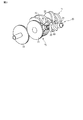
図1は、エンジンのシリンダブロック10の一部と、サプライポンプ20とを示している。サプライポンプ20は、加圧した燃料をインジェクタに供給するための燃料供給系の一部をなしている。図2は、サプライポンプ20をシリンダブロック10に組付ける前の状態を示している。図3にクランクシャフト11とサプライポンプ20などが模式的に示されている。
A supply pump mounting structure for a cylinder block according to the first embodiment will be described below with reference to FIGS.
FIG. 1 shows a part of a
図1に示されるようにシリンダブロック10には、クランクシャフト11の軸線方向に複数(例えば4つ)のシリンダボア12a〜12dが形成されている。シリンダボア12a〜12dは、それぞれシリンダブロック10の上面において開口している。シリンダブロック10の上面にシリンダヘッドが配置される。
As shown in FIG. 1, a plurality (for example, four) of
図4にシリンダブロック10の一部(サプライポンプ取付部15)と、サプライポンプ20と、アダプタ部材40が示されている。アダプタ部材40は、サプライポンプ取付部15に取付けられている。アダプタ部材40にサプライポンプ20が取付けられている。アダプタ部材40については後に詳しく説明する。
FIG. 4 shows a part of the cylinder block 10 (supply pump mounting portion 15), the
サプライポンプ20の構造は図4に限るものではないが、一例としてこのサプライポンプ20は、加圧室を有するシリンダボディ21と、シリンダボディ21の軸線X1に沿う方向に往復運動するタペット22およびプランジャ23と、プランジャ23の往復動作に同期して弁体を開閉させる電磁弁24と、カムフォロア25と、ばね26と、燃料導入管27と、燃料導出管28と、フランジ部29などを備えている。
The structure of the
タペット22とプランジャ23とカムフォロア25とばね26等によってポンプ機構部が構成されている。図2に示されるようにサプライポンプ20をサプライポンプ取付部15に取付ける前の状態では、ポンプ機構部がフランジ部29の下面から外部に露出している。タペット22の側面にガイド溝22aが形成されている。ガイド溝22aは、タペット22が移動する方向(軸線X1に沿う方向)に形成されている。
The
サプライポンプ取付部15はシリンダブロック10の壁面10aの一部をなし、シリンダブロック10の壁面10aから斜め上方に台状に突き出ている。サプライポンプ取付部15の上端側には、壁面10aから離れるにつれて低くなるように傾斜したアダプタ取付面30が形成されている。図8に示されるようにアダプタ取付面30は平坦に機械加工されている。
The supply
サプライポンプ取付部15にアダプタ挿入孔31が形成されている。アダプタ挿入孔31の軸線X2(図8に示す)は、アダプタ取付面30と直角な方向に延び、シリンダブロック10の内側の内部空間10bに連通している。このアダプタ挿入孔31は、アダプタ取付面30において開口する円形の開口部31aを有している。アダプタ挿入孔31の内面31bは円柱形である。このサプライポンプ取付部15には、アダプタ挿入孔31の軸線X2と直角な方向に回り止め取付孔33が形成されている。
An
サプライポンプ取付部15の内部に給油孔35が形成されている。給油孔35は、アダプタ挿入孔31の開口部31aを通じてアダプタ挿入孔31の内部を直接臨むことができる位置から、シリンダブロック10内のオイル供給流路36に向かって一直線に形成されている。
An
すなわちこの給油孔35は、サプライポンプ取付部15の外部から開口部31aを通じて内面31bを臨む位置に、開口部31aの内側を通る直線M(図8に示す)に沿って真っ直ぐに形成されている。しかもこの給油孔35は、アダプタ挿入孔31の軸線X2に対し角度θ1をなして斜めに形成されている。給油孔35の一端35aは、アダプタ挿入孔31の内面31bにおいてオイル噴出口として開口している。給油孔35の他端35bは、シリンダブロック10内のオイル供給流路36に連通している。
That is, the
給油孔35は、開口部31aを通る直線Mに沿う直線形状をなし、かつ、アダプタ挿入孔31の軸線X2に対し角度θ1をなしているため、図8に示すように穴あけ用のドリル等の工具38を開口部31aから挿入し、オイル供給流路36に向けて穴あけ加工を行うことにより、アダプタ挿入孔31の内面31bからオイル供給流路36に達する真っ直ぐな給油孔35を形成することができる。
The
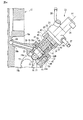
図4と図5に示されるようにサプライポンプ取付部15にアダプタ部材40が取付けられている。図6はアダプタ部材40の斜視図、図7はアダプタ部材40の底面図である。アダプタ部材40は、サプライポンプ取付部15のアダプタ取付面30に接する第1フランジ41と、サプライポンプ20のフランジ部29に接する第2フランジ42と、筒部43と、アダプタ挿入孔31に挿入される筒形の先端部44と、筒部43から先端部44にわたって内側に形成されたポンプ挿入孔45と、回り止め部材46の先端46aが挿入される回り止め挿入孔47と、給油孔35の一端(オイル噴出口)35aに連なる給油連通孔48と、空気逃がし部50とを備えている。先端部44の外径は、この先端部44がアダプタ挿入孔31に丁度嵌合できる寸法としている。
As shown in FIGS. 4 and 5, the
アダプタ部材40の先端部44がアダプタ挿入孔31に挿入された状態において、ポンプ挿入孔45の軸線X3(図5に示す)は、アダプタ挿入孔31の軸線X2(図8に示す)と一致している。回り止め挿入孔47はサプライポンプ取付部15の回り止め取付孔33と対応した位置に形成されている。
In a state where the
図4に示されるように、アダプタ部材40のポンプ挿入孔45に、サプライポンプ20のポンプ機構部(タペット22やプランジャ23、カムフォロア25およびばね26等)が挿入される。回り止め取付孔33には回り止め部材46が挿入される。回り止め部材46の先端46aは、回り止め挿入孔47を通ってガイド溝22aに挿入される。この状態において、タペット22はガイド溝22aに沿って軸線X3に沿う方向に移動可能であり、しかもタペット22がアダプタ部材40に対して軸線X1まわりに回転することが阻止される。
As shown in FIG. 4, the pump mechanism (the
シリンダブロック10内のオイル供給流路36から給油孔35を経て送られてくるオイルは、給油連通孔48を経てタペット22の摺動面に供給される。すなわちタペット22の油溝22bが給油連通孔48と対向する位置まで移動した状態において、給油連通孔48から噴出するオイルが油溝22bに供給される。
Oil sent from the oil
空気逃がし部50は、タペット22の往復運動によってアダプタ部材40の筒部43の内側に生じる空気の脈動(圧力変化)を逃がす機能を有している。このため空気逃がし部50は、タペット22の移動ストロークの両端を越える長さにわたって形成されている。例えば本実施形態の空気逃がし部50は、第1の溝51と第2の溝52(図7に示す)とを含んでいる。
The
空気逃がし部50の第1の溝51と第2の溝52とは、それぞれ、タペット22の移動ストロークの両端を越える範囲に形成されている。しかも第1の溝51と第2の溝52とは、給油孔35と給油連通孔48との延長線X4(図7に示す)に対し、ポンプ挿入孔45の周方向に所定の角度θ2,θ3(例えば+120°と−120°)をなすように周方向に位置をずらして形成されている。第1の溝51と第2の溝52の下端は、それぞれシリンダブロック10内のクランク室に通じている。
The
アダプタ部材40の第1フランジ41と第2フランジ42とは、いずれも2穴フランジであり、それぞれ非円形(略菱形)をなしている。すなわち第1フランジ41は、筒部43の両側の対称位置に形成された一対の取付孔60a,60bを有している。第2フランジ42も、筒部43の両側の対称位置に形成された一対の取付孔62a,62bを有している。
The
アダプタ部材40の先端部44がアダプタ挿入孔31に挿入された状態において、第1フランジ41の取付孔60a,60bにそれぞれ挿入されたボルト61(図1と図2に示す)によって、アダプタ部材40がサプライポンプ取付部15のアダプタ取付面30に固定される。第1フランジ41とアダプタ取付面30との間には、Oリング等のシール部材66が設けられている。第2フランジ42の取付孔62a,62bにそれぞれ挿入されたボルト63(図1に一方を示す)によって、第2フランジ42のポンプ取付面65にサプライポンプ20が固定される。
In a state in which the
図7に示されるように、第1フランジ41の取付孔60a,60bと第2フランジ42の取付孔62a,62bとは、アダプタ部材40の軸線X3(図5に示す)に沿う方向から見て、互いの位置を角度θ4(図7に示す)だけずらしている。θ4の一例は90°である。こうすることにより、取付孔60a,60bに挿入されたボルト61(図1と図2に示す)によってアダプタ部材40をサプライポンプ取付部15に固定する際、ボルト61を回転させる工具が第2フランジ42と干渉することを避けることができる。
As shown in FIG. 7, the mounting
図3に示されるように、クランクシャフト11によって回転するクランク軸ギヤ70にポンプ駆動ギヤ71が噛合っている。ポンプ駆動ギヤ71と同軸にカム72が取付けられている。クランク軸ギヤ70の歯数とポンプ駆動ギヤ71の歯数は同じである。このためクランクシャフト11が1回転すると、クランク軸ギヤ70と反対方向にカム72が1回転する。ポンプ駆動ギヤ71とカム72は、シリンダブロック10の内部空間10bに収容され、カムケース73(図1と図2に示す)によって覆われている。
As shown in FIG. 3, a
図4に示されるように、サプライポンプ取付部15にアダプタ部材40が固定され、アダプタ部材40にサプライポンプ20のポンプ機構部が挿入された状態において、タペット22のカムフォロア25がカム72に接する。エンジンが運転されると、クランクシャフト11(図3に示す)が回転するとともに、クランク軸ギヤ70が回転することによりポンプ駆動ギヤ71とカム72とが回転する。
As shown in FIG. 4, in the state where the
カム72が回転すると、カム山の形状に応じてサプライポンプ20のタペット22が往復運動する。これらクランク軸ギヤ70とポンプ駆動ギヤ71とカム72等は、サプライポンプ20を駆動するためのポンプ駆動系75を構成している。タペット22が往復運動すると、燃料導入管27からシリンダボディ21の加圧室に吸入された燃料が加圧されて燃料導出管28からコモンレール等の燃料蓄圧系に供給され、各シリンダボア12a〜12dごとの燃料噴射弁(インジェクタ)から所定の順序で燃料が燃焼室に噴射される。
When the
本実施形態のサプライポンプ取付構造によれば、ポンプ駆動ギヤ71やカム72等を含むポンプ駆動系75がシリンダブロック10の内部空間10bに収容される。すなわち従来のサプライポンプに設けられていたカムや回転軸を含むポンプ駆動系がシリンダブロック10内に配置されるため、クランクシャフトの回転をサプライポンプに伝えるための伝達経路が簡略化される。しかもシリンダブロック10に後付けするサプライポンプ20の構成が簡略化し外形も小さくなるため、シリンダブロック10の壁面10aからのサプライポンプ20の突出量が小さくなり、エンジンの小形化に寄与することができる。
According to the supply pump mounting structure of the present embodiment, the
また、シリンダブロック10内のオイル供給流路36から供給されるオイルを、アダプタ挿入孔31の内面31bに開口する給油孔35とアダプタ部材40の給油連通孔48とを通じて、サプライポンプ20のタペット22等の摺動部に供給することができる。この給油孔35は、アダプタ挿入孔31の開口部31aに挿入される工具38によって形成することができる。
Further, the oil supplied from the oil
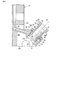
図9は第2の実施形態に係るシリンダブロック10´の一部とアダプタ部材40´を示している。このアダプタ部材40´には、空気逃がし部として機能する連通孔80が形成されている。連通孔80は、シリンダブロック10´に形成された孔81を介してシリンダブロック10´内のクランク室に通じている。それ以外の構成については、第1の実施形態(図1〜図8)と共通であるため、両者に共通の部分に互いに同一の符号を付して説明を省略する。
FIG. 9 shows a part of a
なお本発明を実施するに当たり、シリンダブロックやサプライポンプの具体的な構成や配置をはじめとして、この発明を構成する各要素の構造や形状、配置等の態様をエンジンの仕様に応じて適宜変更して実施できることは言うまでもない。また本発明に係るサプライポンプ取付構造はディーゼルエンジンに限ることはなくガソリンエンジンにも適用可能である。 In practicing the present invention, the specific configuration and arrangement of the cylinder block and the supply pump, as well as the structure, shape, arrangement, etc. of each element constituting the present invention are appropriately changed according to the engine specifications. Needless to say, this can be done. Further, the supply pump mounting structure according to the present invention is not limited to a diesel engine but can be applied to a gasoline engine.
10,10´…シリンダブロック、10a…壁面、10b…内部空間、11…クランクシャフト、15…サプライポンプ取付部、20…サプライポンプ、22…タペット、25…カムフォロア、30…アダプタ取付面、31…アダプタ挿入孔、31a…開口部、31b…内面、33…回り止め取付孔、35…給油孔、35a…一端、35b…他端、36…オイル供給流路、38…工具、40,40´…アダプタ部材、41…第1フランジ、42…第2フランジ、43…筒部、45…ポンプ挿入孔、46…回り止め部材、46a…先端、47…回り止め挿入孔、48…給油連通孔、50…空気逃がし部、51…第1の溝、52…第2の溝、70…クランク軸ギヤ、71…ポンプ駆動ギヤ、72…カム、75…ポンプ駆動系。
DESCRIPTION OF
Claims (6)
前記サプライポンプ取付部に形成され前記シリンダブロックの内部空間に連通しかつ前記アダプタ取付面に開口部を有したアダプタ挿入孔と、
前記開口部から前記アダプタ挿入孔の内面を臨むことができる位置に前記開口部を通る直線に沿って形成され、前記内面から前記オイル供給流路に達する給油孔と、
を具備したことを特徴とするシリンダブロックのサプライポンプ取付構造。 An adapter mounting surface formed in a supply pump mounting portion of a cylinder block having an oil supply flow path;
An adapter insertion hole formed in the supply pump mounting portion and communicating with the internal space of the cylinder block and having an opening in the adapter mounting surface;
An oil supply hole formed along a straight line passing through the opening at a position where the inner surface of the adapter insertion hole can be faced from the opening, and reaching the oil supply flow path from the inner surface;
A supply pump mounting structure for a cylinder block, comprising:
該アダプタ部材は、前記アダプタ取付面に接する第1フランジと、サプライポンプを支持する第2フランジと、前記サプライポンプのポンプ機構部が挿入されるポンプ挿入孔と、前記給油孔に連通する給油連通孔と、を備えたことを特徴とする請求項1に記載のシリンダブロックのサプライポンプ取付構造。 An adapter member inserted into the adapter insertion hole;
The adapter member includes a first flange that contacts the adapter mounting surface, a second flange that supports the supply pump, a pump insertion hole into which the pump mechanism of the supply pump is inserted, and an oil supply communication that communicates with the oil supply hole. The cylinder block supply pump mounting structure according to claim 1, further comprising a hole.
前記アダプタ部材は、前記タペットが移動する軌跡の両端を越える長さを有する空気逃がし部を備えたことを特徴とする請求項2に記載のシリンダブロックのサプライポンプ取付構造。 The pump mechanism includes a tappet,
3. The supply pump mounting structure for a cylinder block according to claim 2, wherein the adapter member includes an air escape portion having a length exceeding both ends of a trajectory in which the tappet moves.
Priority Applications (1)
| Application Number | Priority Date | Filing Date | Title |
|---|---|---|---|
| JP2015255079A JP6610248B2 (en) | 2015-12-25 | 2015-12-25 | Supply pump mounting structure for cylinder block |
Applications Claiming Priority (1)
| Application Number | Priority Date | Filing Date | Title |
|---|---|---|---|
| JP2015255079A JP6610248B2 (en) | 2015-12-25 | 2015-12-25 | Supply pump mounting structure for cylinder block |
Publications (2)
| Publication Number | Publication Date |
|---|---|
| JP2017115825A true JP2017115825A (en) | 2017-06-29 |
| JP6610248B2 JP6610248B2 (en) | 2019-11-27 |
Family
ID=59233966
Family Applications (1)
| Application Number | Title | Priority Date | Filing Date |
|---|---|---|---|
| JP2015255079A Active JP6610248B2 (en) | 2015-12-25 | 2015-12-25 | Supply pump mounting structure for cylinder block |
Country Status (1)
| Country | Link |
|---|---|
| JP (1) | JP6610248B2 (en) |
Cited By (1)
| Publication number | Priority date | Publication date | Assignee | Title |
|---|---|---|---|---|
| JP2019132210A (en) * | 2018-01-31 | 2019-08-08 | いすゞ自動車株式会社 | Lubricating oil supply structure |
-
2015
- 2015-12-25 JP JP2015255079A patent/JP6610248B2/en active Active
Cited By (3)
| Publication number | Priority date | Publication date | Assignee | Title |
|---|---|---|---|---|
| JP2019132210A (en) * | 2018-01-31 | 2019-08-08 | いすゞ自動車株式会社 | Lubricating oil supply structure |
| WO2019151038A1 (en) * | 2018-01-31 | 2019-08-08 | いすゞ自動車株式会社 | Lubricant feeding structure |
| JP7049596B2 (en) | 2018-01-31 | 2022-04-07 | いすゞ自動車株式会社 | Lubricating oil supply structure |
Also Published As
| Publication number | Publication date |
|---|---|
| JP6610248B2 (en) | 2019-11-27 |
Similar Documents
| Publication | Publication Date | Title |
|---|---|---|
| US20080175731A1 (en) | Transfer pump for injection of fuel at high pressure | |
| US8307799B2 (en) | Lubrication system for fuel pump of GDI engine | |
| CN104612958A (en) | A pump | |
| CN107587910B (en) | Lubricant supply device for a chain in an internal combustion engine | |
| EP2620633A1 (en) | Pump head for a fuel pump | |
| JP2007500312A (en) | Pump assembly | |
| JP2006170184A (en) | High pressure fuel pump | |
| US7950373B2 (en) | Check valve with separate spherical spring guide | |
| JP6610248B2 (en) | Supply pump mounting structure for cylinder block | |
| ATE417200T1 (en) | HIGH PRESSURE PUMP FOR A FUEL INJECTION DEVICE OF AN INTERNAL COMBUSTION ENGINE | |
| CA2889356C (en) | Chain saw and fluid pump | |
| US20110200463A1 (en) | Pump, particularly high-pressure fuel pump | |
| EP2088309A1 (en) | High-pressure fuel feed pump | |
| KR100475987B1 (en) | High-pressure fuel feed device | |
| WO2017094438A1 (en) | Relief valve device and high-pressure pump using same | |
| JP2013194616A (en) | High pressure fuel supply pump | |
| JP6239094B2 (en) | Fuel injection pump | |
| CN110121593B (en) | Pump assembly for supplying fuel, preferably diesel fuel, to an internal combustion engine | |
| JP2015214974A (en) | Fluid valve assembly | |
| JP2005188379A (en) | Check valve and fuel injection pump equipped with the check valve | |
| JP6570309B2 (en) | Fuel supply pump | |
| WO2013129401A1 (en) | Fuel injection pump and internal combustion engine | |
| JP5840865B2 (en) | Fuel pump | |
| EP3283764B1 (en) | High pressure diesel fuel pumps | |
| WO2013136964A1 (en) | Fuel injection pump |
Legal Events
| Date | Code | Title | Description |
|---|---|---|---|
| A621 | Written request for application examination |
Free format text: JAPANESE INTERMEDIATE CODE: A621 Effective date: 20181130 |
|
| TRDD | Decision of grant or rejection written | ||
| A977 | Report on retrieval |
Free format text: JAPANESE INTERMEDIATE CODE: A971007 Effective date: 20190925 |
|
| A01 | Written decision to grant a patent or to grant a registration (utility model) |
Free format text: JAPANESE INTERMEDIATE CODE: A01 Effective date: 20191001 |
|
| A61 | First payment of annual fees (during grant procedure) |
Free format text: JAPANESE INTERMEDIATE CODE: A61 Effective date: 20191014 |
|
| R150 | Certificate of patent or registration of utility model |
Ref document number: 6610248 Country of ref document: JP Free format text: JAPANESE INTERMEDIATE CODE: R150 |