JP2017115748A - Engine with breather device - Google Patents

Engine with breather device Download PDF

Info

Publication number
JP2017115748A
JP2017115748A JP2015253187A JP2015253187A JP2017115748A JP 2017115748 A JP2017115748 A JP 2017115748A JP 2015253187 A JP2015253187 A JP 2015253187A JP 2015253187 A JP2015253187 A JP 2015253187A JP 2017115748 A JP2017115748 A JP 2017115748A
Authority
JP
Japan
Prior art keywords
separation chamber
engine
oil
oil separation
gas
Prior art date
Legal status (The legal status is an assumption and is not a legal conclusion. Google has not performed a legal analysis and makes no representation as to the accuracy of the status listed.)
Granted
Application number
JP2015253187A
Other languages
Japanese (ja)
Other versions
JP6475608B2 (en
Inventor
木本 清治
Seiji Kimoto
清治 木本
Current Assignee (The listed assignees may be inaccurate. Google has not performed a legal analysis and makes no representation or warranty as to the accuracy of the list.)
Kubota Corp
Original Assignee
Kubota Corp
Priority date (The priority date is an assumption and is not a legal conclusion. Google has not performed a legal analysis and makes no representation as to the accuracy of the date listed.)
Filing date
Publication date
Application filed by Kubota Corp filed Critical Kubota Corp
Priority to JP2015253187A priority Critical patent/JP6475608B2/en
Publication of JP2017115748A publication Critical patent/JP2017115748A/en
Application granted granted Critical
Publication of JP6475608B2 publication Critical patent/JP6475608B2/en
Active legal-status Critical Current
Anticipated expiration legal-status Critical

Links

Images

Abstract

PROBLEM TO BE SOLVED: To provide an engine including a breather device in which advantage attained by a simple structure is not damaged, excessive oil consumption is not attained, reduction of blowby gas can be carried out, reduction in engine oil deterioration as well as durability of an engine are improved.SOLUTION: This invention relates to an engine provided with a breather device in which an oil separation chamber 4 in respect to blowby gas is constituted at an outside part of an engine machine wall 3, a starting end side of the oil separation chamber 4 is provided with a gas inlet hole 5 opened into an engine machine [k], a terminal end side of the oil separation chamber is provided with a gas outlet 25 for reducing blowby gas at an intake system, a location near the gas inlet hole 5 and the terminal end side of the oil separation chamber 4 are provided with return holes 33, 34. The starting end side return hole 33 is formed to be adjacent to a metal mesh 35 installed in the engine machine [k] and the terminal end side return hole 34 is formed to be directly adjacent to the engine machine [k].SELECTED DRAWING: Figure 1

Description

本発明は、汎用エンジンなどのブリーザ装置付エンジンに係り、詳しくは、クランクケース内に生じたブローバイガスからオイル成分を分離して吸気系に還元するためのオイル分離室が、エンジン機壁の外側にエンジン機壁を用いて構成されているブリーザ装置付エンジンに関するものである。   The present invention relates to a breather-equipped engine such as a general-purpose engine, and more specifically, an oil separation chamber for separating an oil component from blow-by gas generated in a crankcase and returning it to an intake system is provided outside the engine machine wall. The present invention relates to an engine with a breather device that is configured using an engine machine wall.

4ストロークエンジンなどの内燃機関においては、クランクケース内部はブローバイガスや温度上昇に伴う空気の膨張、オイルの蒸気によって外気よりも圧力が高くなる。この圧力を逃がして解放するために設けられているのがブリーザ装置で、最も単純なものは外気へ直接解放する方式である。   In an internal combustion engine such as a 4-stroke engine, the pressure inside the crankcase becomes higher than that of the outside air due to blow-by gas, air expansion associated with temperature rise, and oil vapor. A breather device is provided to relieve and release this pressure, and the simplest is a system that directly releases to the outside air.

しかしながら、ブローバイガスは未燃焼炭化水素などの大気汚染物質を高濃度で含むことから、トラクタ、自動車、産業用エンジンなどでは吸気管へと還元する構造がとられる。また、ブローバイガス成分によってエンジンオイルが汚れたり、希釈されたりするため、リード弁、一方弁などによるPCVバルブと呼ばれる逆止弁を用いてブローバイガスを積極的にクランクケース外部へ排出する方式が採用されていることも多い。   However, since blow-by gas contains air pollutants such as unburned hydrocarbons in high concentration, a structure for reducing it to an intake pipe is adopted in tractors, automobiles, industrial engines, and the like. Also, because the engine oil is contaminated or diluted by the blow-by gas component, a system that positively discharges the blow-by gas to the outside of the crankcase using a check valve called a PCV valve such as a reed valve or one-way valve is adopted. It is often done.

ブローバイガスのブリーザ装置付エンジンとしては、特許文献1において開示されたものが知られている。特許文献1においては、シリンダ上端部に及ぶ状態でシリンダヘッドの壁内側にブリーザ装置の要部である二つのオイル分離室(気液分離室:43,45)が形成されている。下側の気液分離室(43)の下端部であるガス導入口(52)から流入したブローバイガスは、気液分離室(43),(45)、及びパイプでなるブローバイ通路(46)を経てエアクリーナ(47)に還元される。   As an engine with a breather device for blow-by gas, an engine disclosed in Patent Document 1 is known. In Patent Literature 1, two oil separation chambers (gas-liquid separation chambers: 43 and 45), which are the main parts of the breather device, are formed inside the cylinder head wall in a state extending to the upper end of the cylinder. The blow-by gas that has flowed in from the gas inlet (52), which is the lower end of the lower gas-liquid separation chamber (43), passes through the gas-liquid separation chambers (43) and (45) and the blow-by passage (46) made of pipes. After that, it is returned to the air cleaner (47).

気液分離室(43),(45)で分離されたオイルは、オイルリターン孔からチェーン室(51)に流出させるが、ガス導入口(52)の傾斜面を伝ってチェーン室(50)に流下するようにも構成されている。つまり、特許文献1においては、ブローバイガスの通り道における壁面への付着によりオイルを分離させるものであり、その分離されたオイルは、単純な孔や通路を通してクランクケース内への戻すシンプルな構成とされていた。   The oil separated in the gas-liquid separation chambers (43) and (45) flows out from the oil return hole to the chain chamber (51), but flows along the inclined surface of the gas inlet (52) to the chain chamber (50). It is also configured to flow down. That is, in Patent Document 1, the oil is separated by adhering to the wall surface in the passage of blow-by gas, and the separated oil has a simple configuration for returning to the crankcase through a simple hole or passage. It was.

このようなシンプル構造のブリーザ装置では、構造簡単で廉価に構成できる利点はあるが、エンジン状態に応じてブローバイガスからオイル分離させる制御までは行えない。そのため、オイルが十分に分離しきれないまま吸気系にブローバイガスが還元され、オイル消費量が多く、エンジンオイルが早期に減ってしまうとか汚れ易いといった問題が生じ易い傾向にあった。   Such a breather apparatus having a simple structure has an advantage that the structure is simple and can be constructed at low cost, but it cannot perform control for separating oil from blow-by gas according to the engine state. For this reason, blow-by gas is reduced to the intake system without the oil being sufficiently separated, so that there is a tendency for the oil consumption to be large and the engine oil to be reduced at an early stage or to be easily contaminated.

特開2002−242649号公報JP 2002-242649 A

本発明の目的は、オイル分離室のさらなる構造見直しを行うことにより、構造簡単による利点を損なうことなく、オイル消費が過剰となってしまうことなくブローバイガスの還元が行え、エンジンオイル劣化の低減、ひいてはエンジンの耐久性が改善されるブリーザ装置付エンジンを提供する点にある。   The object of the present invention is to further reduce the structure of the oil separation chamber, thereby reducing the blow-by gas without losing excessive oil consumption without losing the advantages of the simple structure, reducing engine oil deterioration, As a result, an engine with a breather device that improves the durability of the engine is provided.

請求項1に係る発明は、クランクケース1内に生じたブローバイガスからオイル成分を分離して吸気系に還元するためのオイル分離室4が、エンジン機壁3の外側に前記エンジン機壁3を用いて構成されているブリーザ装置付エンジンであって、
前記オイル分離室4の始端側に、クランクケース1内と連通しているエンジン機内kに開口するガス入口孔5が前記エンジン機壁3に設けられるとともに、前記オイル分離室4の終端側に、前記吸気系にブローバイガスを還元するためのガス出口25が設けられ、
前記オイル分離室4の始端側の前記ガス入口孔5の近傍箇所、及び前記オイル分離室4の終端側の前記ガス出口25の近傍箇所のそれぞれにおける前記エンジン機壁3に、前記オイル分離室4において分離されたオイル成分を前記エンジン機内kに戻すための戻し孔33,34が設けられ、
前記始端側の戻し孔33は、前記ガス入口孔5に及ぶ手前においてブローバイガス中のオイル成分を捕捉するために前記エンジン機内kに装備されたオイル捕捉促進具35に臨む状態に形成され、かつ、前記終端側の戻し孔34は直接前記エンジン機内kに臨む状態に形成されていることを特徴とする。
In the invention according to claim 1, an oil separation chamber 4 for separating an oil component from blow-by gas generated in the crankcase 1 and reducing it to the intake system is provided with the engine machine wall 3 outside the engine machine wall 3. An engine with a breather device configured to be used,
A gas inlet hole 5 opened to the engine machine wall k communicating with the inside of the crankcase 1 is provided in the engine machine wall 3 on the start end side of the oil separation chamber 4, and on the terminal side of the oil separation chamber 4, A gas outlet 25 for reducing blow-by gas in the intake system is provided,
The oil separation chamber 4 is provided on the engine machine wall 3 in the vicinity of the gas inlet hole 5 on the start side of the oil separation chamber 4 and in the vicinity of the gas outlet 25 on the end side of the oil separation chamber 4. Return holes 33 and 34 are provided for returning the oil components separated in step 1 to the engine interior k.
The return hole 33 on the start end side is formed so as to face an oil trapping promoting tool 35 provided in the engine interior k in order to trap the oil component in the blow-by gas before reaching the gas inlet hole 5, and The terminal-side return hole 34 is formed so as to directly face the engine cabin k.

請求項2に係る発明は、請求項1に記載のブリーザ装置付エンジンにおいて、
前記オイル分離室4内にガイド壁8を設け、このガイド壁8でガス入口孔5からガス出口25までのオイル分離室内経路9を蛇行させた構成とされていることを特徴とする。
The invention according to claim 2 is the engine with a breather device according to claim 1,
A guide wall 8 is provided in the oil separation chamber 4, and the oil separation chamber path 9 from the gas inlet hole 5 to the gas outlet 25 is meandered by the guide wall 8.

請求項3に係る発明は、請求項2に記載のブリーザ装置付エンジンにおいて、
前記オイル分離室4の分離室周壁15と前記ガイド壁8とが前記エンジン機壁3に一体形成され、前記分離室周壁15の先端開口部16を覆って閉塞するブリーザカバー20を設けて前記オイル分離室4が構成されており、前記ブリーザカバー20に前記ガス出口25が設けられるとともに、前記吸気系である吸気管24と前記ガス出口25とを連通するブリーザパイプ26が装備されていることを特徴とする。
The invention according to claim 3 is the engine with a breather device according to claim 2,
A separation chamber peripheral wall 15 of the oil separation chamber 4 and the guide wall 8 are formed integrally with the engine machine wall 3, and a breather cover 20 that covers and closes a front end opening 16 of the separation chamber peripheral wall 15 is provided. The separation chamber 4 is configured, the breather cover 20 is provided with the gas outlet 25, and a breather pipe 26 that communicates the intake pipe 24 that is the intake system and the gas outlet 25 is provided. Features.

請求項4に係る発明は、請求項3に記載のブリーザ装置付エンジンにおいて、
前記先端開口部16と前記ブリーザカバー20との間に、先端開口部16の蓋となるリード弁取付板17、及び前記リード弁取付板17に形成されたリード孔18を用いる状態で前記リード弁取付板17に支持されるリードバルブ19を設けて、前記オイル分離室4を、前記ガス入口孔5側の分離本室4Aと前記ガス出口25側の分離後室4Bとに仕切るとともに、
前記リードバルブ19は、前記分離本室4Aの圧よりも前記分離後室4Bの圧が低くなると開弁する一方弁に構成されていることを特徴とする。
The invention according to claim 4 is the engine with a breather device according to claim 3,
The reed valve is used in a state in which a reed valve mounting plate 17 serving as a lid of the front end opening 16 and a reed hole 18 formed in the reed valve mounting plate 17 are used between the front end opening 16 and the breather cover 20. A reed valve 19 supported by the mounting plate 17 is provided to partition the oil separation chamber 4 into a separation main chamber 4A on the gas inlet hole 5 side and a post-separation chamber 4B on the gas outlet 25 side,
The reed valve 19 is configured as a one-way valve that opens when the pressure in the post-separation chamber 4B is lower than the pressure in the separation main chamber 4A.

請求項5に係る発明は、請求項4に記載のブリーザ装置付エンジンにおいて、
前記リード孔18は、前記分離本室4Aにおける蛇行された前記オイル分離室内経路9の終端近傍に臨む位置に形成されていることを特徴とする。
The invention according to claim 5 is the engine with a breather device according to claim 4,
The lead hole 18 is formed at a position facing the vicinity of the end of the meandering oil separation chamber path 9 in the separation main chamber 4A.

請求項6に係る発明は、請求項2〜5の何れか一項に記載のブリーザ装置付エンジンにおいて、
前記分離室周壁15に、前記オイル分離室内経路9の後部又は終端近傍に臨む脈動孔6が形成され、前記脈動孔6に連通パイプ7を介して脈動圧作動器2を連通させ、前記クランクケース1内の脈動圧で前記脈動圧作動器2が駆動される状態に構成されていることを特徴とする。
The invention according to claim 6 is the engine with a breather device according to any one of claims 2 to 5,
A pulsation hole 6 facing the rear part or near the end of the oil separation chamber path 9 is formed in the separation chamber peripheral wall 15, and the pulsation pressure actuator 2 is communicated with the pulsation hole 6 through a communication pipe 7. The pulsation pressure actuator 2 is driven by the pulsation pressure within 1.

請求項1の発明によれば、ガス入口孔からオイル分離室に流入したブローバイガス(オイルミストを多く含んだブローバイガス)は、オイル分離室においてオイル成分の分離作用を受け、分離作用を受けた後のブローバイガスはガス出口から吸気系に還元されるとともに、分離されたオイル成分は2つの戻し孔からエンジン機内に戻される。
オイル分離室にて分離されたオイル成分は、エンジン機内側にオイル捕捉促進具のある始端側の戻し孔からは穏やかにエンジン機内に戻り、終端側の戻し孔からは素早くエンジン機内に戻るようになる。
この戻り速度に差のある二つの戻し孔から捕捉されたオイル成分をエンジン機内に戻す構成の採用により、ブローバイガスの還元作用を促進させるようにしながら、分離されたオイルの戻し作用の強化が図ることが可能になった。
その結果、オイル分離室のさらなる構造見直しを行うことにより、構造簡単による利点を損なうことなく、オイル消費が過剰となってしまうことなくブローバイガスの還元が行え、エンジンオイル劣化の低減、ひいてはエンジンの耐久性が改善されるブリーザ装置付エンジンを提供することができる。
According to the first aspect of the present invention, blow-by gas (blow-by gas containing a large amount of oil mist) flowing into the oil separation chamber from the gas inlet hole is subjected to the separation action of the oil component in the oil separation chamber and is subjected to the separation action. The subsequent blow-by gas is reduced from the gas outlet to the intake system, and the separated oil component is returned to the engine machine from the two return holes.
The oil component separated in the oil separation chamber gently returns to the engine machine from the return hole on the start side where the oil catching promotion tool is located inside the engine machine, and quickly returns to the engine machine from the return hole on the end side. Become.
By adopting a configuration in which the oil component captured from the two return holes having a difference in return speed is returned to the engine machine, the return action of the separated oil is enhanced while promoting the reduction action of blow-by gas. It became possible.
As a result, by further reviewing the structure of the oil separation chamber, it is possible to reduce blow-by gas without losing the oil consumption without losing the advantages of the simple structure, reducing engine oil deterioration, and thus the engine An engine with a breather device with improved durability can be provided.

請求項2の発明によれば、オイル分離室内に設けられたガイド壁により、オイル分離室内経路9が蛇行するようになるので、クランクケース1からオイル分離室4に流入してきたオイルミストは、蛇行するオイル分離室内経路を通過する過程で容易に凝集されるようになる。従って、ブローバイガス中のオイルミストが過剰にガス出口から吸気系にもどされて消費されてしまうことが抑制され、オイルの早期減少がより有効に制限又は防止される利点がある。   According to the invention of claim 2, the oil separation chamber path 9 meanders due to the guide wall provided in the oil separation chamber, so that the oil mist flowing into the oil separation chamber 4 from the crankcase 1 It is easily agglomerated in the process of passing through the oil separation chamber. Accordingly, there is an advantage that the oil mist in the blow-by gas is excessively returned to the intake system from the gas outlet and consumed, and the early reduction of oil is more effectively limited or prevented.

請求項3の発明によれば、オイル分離室における先端開口部を覆って閉塞するブリーザカバーを配置し、ブリーザカバーに形成されているガス出口と吸気管とをブリーザパイプで連通してあるから、ガス出口と吸気管とを近づけて、ブリーザパイプを短くすることができる。従って、ブリーザパイプの通路抵抗が小さくなり、ブリーザ機能を高めることができる。   According to the invention of claim 3, the breather cover that covers and closes the tip opening in the oil separation chamber is disposed, and the gas outlet formed in the breather cover and the intake pipe are communicated with each other by the breather pipe. The breather pipe can be shortened by bringing the gas outlet and the intake pipe close to each other. Accordingly, the passage resistance of the breather pipe is reduced, and the breather function can be enhanced.

請求項4の発明によれば、リード弁取付板をオイル分離室に設けて、オイル分離室を、蛇行するオイル分離室内経路を有する分離本室と分離後室とに分けてあるから、ブローバイガスに含まれるオイルミストは分離本室とリードバルブとで二重にオイル分離されている。従って、ブリーザ装置におけるオイル分離機能が高められる利点がある。   According to the invention of claim 4, the reed valve mounting plate is provided in the oil separation chamber, and the oil separation chamber is divided into a separation main chamber having a meandering oil separation chamber path and a separation rear chamber. The oil mist contained in is separated into oil by the separation main chamber and the reed valve. Therefore, there is an advantage that the oil separation function in the breather device is enhanced.

請求項5の発明によれば、リード孔が、分離本室における蛇行されたオイル分離室内経路の終端近傍に臨む位置に形成されているから、ガス出口及び分離後室を通って吸気系に戻されるブローバイガスは、オイル分離室によるオイルの分離作用を十分に受けた状態となり、この点からもブリーザ装置の機能が高められる利点がある。   According to the invention of claim 5, since the lead hole is formed at a position facing the end of the meandering oil separation chamber path in the separation main chamber, it is returned to the intake system through the gas outlet and the separation rear chamber. The blow-by gas that has been sufficiently subjected to the oil separation action by the oil separation chamber is advantageous in that the function of the breather device can be enhanced.

請求項6の発明によれば、ブローバイガスからオイル成分を分離させるブリーザ装置を、燃料ポンプなどの脈動圧作動器の駆動源にもすることができ、装置の兼用化による合理化が促進される利点がある。   According to the invention of claim 6, the breather device for separating the oil component from the blow-by gas can be used as a drive source for a pulsation pressure actuator such as a fuel pump, and the rationalization by the combined use of the device is promoted. There is.

ブリーザ装置を示し、(a)はシリンダヘッドの外壁に組付けられた状態のオイル分離室、(b)は分解状態における装置全体の模式図The breather device is shown, (a) is an oil separation chamber assembled to the outer wall of the cylinder head, and (b) is a schematic view of the entire device in a disassembled state. 図1(a)のII−II線断面図II-II line sectional view of FIG. エアクリーナとファンケースを省略した状態の空冷V型エンジンの平面図Top view of an air-cooled V-type engine with the air cleaner and fan case omitted ファンケースとエンジン冷却ファンとエアクリーナを省略した状態の空冷V型エンジンの正面図Front view of an air-cooled V-type engine with the fan case, engine cooling fan, and air cleaner omitted 図4の右側面図Right side view of FIG. 図4の背面図Rear view of FIG. 別実施形態による空冷V型エンジンのファンケースを省略した状態の正面図The front view of the state which omitted the fan case of the air-cooled V-type engine by another embodiment 図7のエンジンの下部ファンケースが着いた状態での上から見た斜視図FIG. 7 is a top perspective view of the engine shown in FIG. 7 with the lower fan case attached.

以下に、本発明によるブリーザ装置付エンジンの実施の形態を、汎用エンジンである空冷V型エンジンに適用した場合ついて、図面を参照しながら説明する。   Hereinafter, a case where an embodiment of an engine with a breather device according to the present invention is applied to an air-cooled V-type engine which is a general-purpose engine will be described with reference to the drawings.

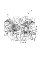
本発明による空冷V型エンジンは、図6に示されるように、クランクケース1内の脈動圧で脈動圧作動器2が駆動される。このエンジンEは、図3に示されるように、エンジンを上方から見て、クランク軸21の軸線21aよりも右寄りに脈動圧作動器2とオイル分離室4とが配置された右ポンプ仕様エンジンである。図示は省略するが、脈動圧作動器2とオイル分離室4とを、クランク軸21の軸線21aよりもよりも左寄りに配置した左ポンプ仕様エンジンもある。脈動圧作動器2の例としては、燃料タンクからキャブレタ29のフロート室に燃料を供給するための脈動圧ポンプである。以下、右ポンプ仕様のもので説明する。   In the air-cooled V-type engine according to the present invention, the pulsation pressure actuator 2 is driven by the pulsation pressure in the crankcase 1 as shown in FIG. As shown in FIG. 3, the engine E is a right pump engine in which a pulsation pressure actuator 2 and an oil separation chamber 4 are arranged on the right side of the axis 21a of the crankshaft 21 when the engine is viewed from above. is there. Although not shown, there is also a left-pump engine in which the pulsation pressure actuator 2 and the oil separation chamber 4 are arranged to the left of the axis 21a of the crankshaft 21. An example of the pulsation pressure actuator 2 is a pulsation pressure pump for supplying fuel from a fuel tank to the float chamber of the carburetor 29. Hereinafter, the description will be made with the right pump specification.

図6に示されるように、シリンダブロック27はクランクケース1と一対のシリンダ22,22との一体成型品である。クランク軸21の架設方向と平行な向きに見て、クランクケース1から左右斜め上向きに一対のシリンダ22,22が突出されている。左右のシリンダ22の突出端には左右のシリンダヘッド11がそれぞれ組み付けられ、左右のシリンダヘッド11にそれぞれ左右のヘッドカバー12が組み付けられている。   As shown in FIG. 6, the cylinder block 27 is an integrally molded product of the crankcase 1 and the pair of cylinders 22 and 22. A pair of cylinders 22 and 22 project from the crankcase 1 obliquely upward and leftward when viewed in a direction parallel to the direction in which the crankshaft 21 is erected. The left and right cylinder heads 11 are assembled to the protruding ends of the left and right cylinders 22, respectively, and the left and right head covers 12 are assembled to the left and right cylinder heads 11, respectively.

図3に示されるように、左右のシリンダヘッド11,11の前部には吸気マニホルド28が架設され、吸気マニホルド28の中央部後方にはキャブレタ29が取付けられている。キャブレタ29の後部には吸気管24が取付けられ、図6に示されるように、吸気管24にはエアクリーナ30が連通されている。図示は省略するが、シリンダブロック27の前部には、エンジン冷却ファンを収容するファンケースが配置されている。   As shown in FIG. 3, an intake manifold 28 is installed in front of the left and right cylinder heads 11, 11, and a carburetor 29 is attached to the rear of the central portion of the intake manifold 28. An intake pipe 24 is attached to the rear part of the carburetor 29, and an air cleaner 30 is communicated with the intake pipe 24 as shown in FIG. Although not shown, a fan case that houses the engine cooling fan is disposed at the front of the cylinder block 27.

図3に示されるように、右ポンプ仕様エンジンは、エンジンを上方から見て、クランク軸21の軸線21aよりも右寄りに脈動圧作動器2とオイル分離室4とが配置されている。右側のエンジン機壁3である右側のシリンダヘッド11のシリンダヘッド壁10の外側にオイル分離室4が形成されている。   As shown in FIG. 3, in the right pump specification engine, the pulsation pressure actuator 2 and the oil separation chamber 4 are disposed on the right side of the axis 21 a of the crankshaft 21 when the engine is viewed from above. An oil separation chamber 4 is formed outside the cylinder head wall 10 of the right cylinder head 11 which is the right engine machine wall 3.

図1(a),(b)及び図2に示されるように、オイル分離室4の始端側に、クランクケース1内と連通する分離室への入口であるガス入口孔5、及び分離室からの出口であるガス出口25がそれぞれ形成され、オイル分離室4の終端側に、脈動を取出すための脈動孔6が形成されている。脈動孔6には連通パイプ7を用いて脈動圧作動器2が連通され、その結果、脈動圧作動器2はオイル分離室4を介してクランクケース1内に連通されている。   As shown in FIGS. 1 (a), 1 (b) and 2, the oil separation chamber 4 has a gas inlet hole 5 which is an inlet to the separation chamber communicating with the inside of the crankcase 1 and the separation chamber. A gas outlet 25 is formed, and a pulsation hole 6 for taking out pulsation is formed on the terminal side of the oil separation chamber 4. The pulsation pressure actuator 2 is communicated with the pulsation hole 6 using a communication pipe 7, and as a result, the pulsation pressure actuator 2 is communicated with the crankcase 1 via the oil separation chamber 4.

オイル分離室4内には複数のガイド壁8が設けられ、それらガイド壁8によりガス入口孔5から脈動孔6及びリード孔18(後述)までのオイル分離室内経路9が蛇行されている。また、図3に示されるように、右側のシリンダヘッド11に被せたヘッドカバー12と隣り合う位置に脈動圧作動器2が配置されている。シリンダブロック27内とガス入口孔5とは、プッシュロッド室31に並設された連通孔32により連通されている。連通孔32はシリンダヘッド11内とシリンダブロック27内に一連に形成されている。   A plurality of guide walls 8 are provided in the oil separation chamber 4, and these guide walls 8 meander an oil separation chamber path 9 from the gas inlet hole 5 to the pulsation hole 6 and the lead hole 18 (described later). Further, as shown in FIG. 3, the pulsation pressure actuator 2 is disposed at a position adjacent to the head cover 12 that covers the right cylinder head 11. The inside of the cylinder block 27 and the gas inlet hole 5 are communicated with each other through a communication hole 32 provided in parallel with the push rod chamber 31. The communication holes 32 are formed in series in the cylinder head 11 and the cylinder block 27.

図1(a),(b)及び図2に示されるように、右寄りの分離室周壁15内の始端側にクランクケース1内と連通するガス入口孔5が形成され、分離室周壁15内の終端側に脈動孔6が形成され、分離室周壁15の先端開口部16はリード弁取付板17で蓋されている。故に、分離室周壁15内が実質的なオイル分離室4となり、ガス入口孔5から脈動孔6までのオイル分離室内経路9がガイド壁8によって蛇行する構成とされている。なお、分離後室4Bにおいてもリード弁取付板17により、オイル分離室内経路9の終端部→リード孔18→ガス出口25と続く経路が蛇行されている構成と言える。オイル分離室4の脈動孔6に連通パイプ7を介して脈動圧作動器2が連通され、右寄りの脈動圧作動器2が右寄りのオイル分離室4を介してシリンダブロック27内に連通されている。ガス入口孔5と脈動孔6とは、エンジン機壁3と分離室周壁にキリ加工で形成されている。   As shown in FIGS. 1A, 1B, and 2, a gas inlet hole 5 communicating with the inside of the crankcase 1 is formed on the start end side in the separation chamber peripheral wall 15 on the right side. A pulsation hole 6 is formed on the end side, and a leading end opening 16 of the separation chamber peripheral wall 15 is covered with a reed valve mounting plate 17. Therefore, the inside of the separation chamber peripheral wall 15 becomes the substantial oil separation chamber 4, and the oil separation chamber path 9 from the gas inlet hole 5 to the pulsation hole 6 meanders by the guide wall 8. In the post-separation chamber 4B, it can be said that the reed valve mounting plate 17 meanders the path continuing from the end portion of the oil separation chamber path 9 to the lead hole 18 to the gas outlet 25. The pulsation pressure actuator 2 is communicated with the pulsation hole 6 of the oil separation chamber 4 via the communication pipe 7, and the right pulsation pressure actuator 2 is communicated with the inside of the cylinder block 27 via the right oil separation chamber 4. . The gas inlet hole 5 and the pulsation hole 6 are formed in the engine machine wall 3 and the separation chamber peripheral wall by drilling.

図3に示されるように、脈動圧作動器2の取付ステー13とヘッドカバー12とが、取付ボルト14でシリンダヘッド11に共締めで取付けられている。図1(a),(b)に示されるように、分離室周壁15の先端開口部16がリード弁取付板17で蓋されることでオイル分離室4が形成され、リード弁取付板17にリード孔18とリードバルブ19とが設けられている。リード弁取付板17はブリーザカバー20で覆われるとともに、オイル分離室4にブリーザカバー20が重ねて取付けられており、ブリーザカバー20にはガス出口25が形成されている。   As shown in FIG. 3, the mounting stay 13 and the head cover 12 of the pulsating pressure actuator 2 are attached to the cylinder head 11 with the mounting bolts 14 together. As shown in FIGS. 1 (a) and 1 (b), the oil separation chamber 4 is formed by covering the leading end opening 16 of the separation chamber peripheral wall 15 with the reed valve mounting plate 17, and the reed valve mounting plate 17 A lead hole 18 and a reed valve 19 are provided. The reed valve mounting plate 17 is covered with a breather cover 20, and the breather cover 20 is attached to the oil separation chamber 4 in an overlapping manner, and a gas outlet 25 is formed in the breather cover 20.

そして、図1(b)、図3に示されるように、リード孔18はオイル分離室4の脈動孔6寄りの端部に臨む状態に配置されており、ガス入口孔5とリード孔18とは蛇行するオイル分離室内経路9により連通されている。クランクケース1の上方スペース23に吸気管24が配置され、その上方スペース23に臨む位置で、エンジン機壁3にオイル分離室4とブリーザカバー20とが重ねて配置され、分離室周壁15とブリーザカバー20とによってオイル分離室4が形成されている。ブリーザカバー20のガス出口25はオイル分離室4のガス出口25であって、そのガス出口25と吸気管24とがブリーザパイプ26で連通されている。   As shown in FIGS. 1B and 3, the lead hole 18 is disposed so as to face the end of the oil separation chamber 4 near the pulsation hole 6, and the gas inlet hole 5, the lead hole 18, Are communicated by a meandering oil separation chamber path 9. The intake pipe 24 is disposed in the upper space 23 of the crankcase 1, and the oil separation chamber 4 and the breather cover 20 are disposed on the engine machine wall 3 so as to face the upper space 23, and the separation chamber peripheral wall 15 and the breather are disposed. An oil separation chamber 4 is formed by the cover 20. A gas outlet 25 of the breather cover 20 is a gas outlet 25 of the oil separation chamber 4, and the gas outlet 25 and the intake pipe 24 are communicated with each other by a breather pipe 26.

次に、ブローバイガスの観点から、主にオイル分離室4によるブリーザ装置Aについて詳しく説明する。
ブリーザ装置付エンジンEにおいては、クランクケース1内に生じたブローバイガスからオイル成分を分離して吸気系に還元するためのオイル分離室4が、エンジン機壁3の外側にエンジン機壁3を用いて構成されている。オイル分離室4の始端側に、クランクケース1内と連通している連通孔32(エンジン機内kの一例)に開口するガス入口孔5がエンジン機壁3に設けられている。オイル分離室4の終端側に、吸気管24(吸気系の一例)にブリーザパイプ26を介してブローバイガスを還元するためのガス出口25が設けられている。
つまり、ブリーザ装置Aは、オイル分離室4と、このオイル分離室4へのブローバイガスの給排構造部(ブリーザパイプ26、プッシュロッド室31、連通孔32など)とから構成されている。
Next, from the viewpoint of blow-by gas, the breather apparatus A mainly using the oil separation chamber 4 will be described in detail.
In the engine E with the breather device, the oil separation chamber 4 for separating the oil component from the blow-by gas generated in the crankcase 1 and reducing it to the intake system uses the engine machine wall 3 outside the engine machine wall 3. Configured. A gas inlet hole 5 that opens to a communication hole 32 (an example of an engine interior k) that communicates with the inside of the crankcase 1 is provided in the engine machine wall 3 on the start end side of the oil separation chamber 4. On the end side of the oil separation chamber 4, a gas outlet 25 for reducing blow-by gas through a breather pipe 26 is provided in an intake pipe 24 (an example of an intake system).
That is, the breather device A is composed of an oil separation chamber 4 and a blowby gas supply / exhaust structure portion (a breather pipe 26, a push rod chamber 31, a communication hole 32, etc.) to the oil separation chamber 4.

オイル分離室4の始端側のガス入口孔5の近傍箇所、及びオイル分離室4の終端側のガス出口25の近傍箇所のそれぞれにおけるエンジン機壁3に、オイル分離室4において分離されたオイル成分をエンジン機内kに戻すための戻し孔33,34が設けられている。
始端側の戻し孔33は、ガス入口孔5に及ぶ手前においてブローバイガス中のオイル成分を捕捉するために連通孔32に装備された金属メッシュ(オイル捕捉促進具の一例)35に臨む状態に形成されている。終端側の戻し孔34は直接プッシュロッド室31(エンジン機内kの一例)に臨む状態に形成されている。
Oil components separated in the oil separation chamber 4 on the engine wall 3 in the vicinity of the gas inlet hole 5 on the start end side of the oil separation chamber 4 and in the vicinity of the gas outlet 25 on the end side of the oil separation chamber 4. Return holes 33, 34 are provided for returning the engine to the engine cabin k.
The return hole 33 on the start end side is formed so as to face a metal mesh (an example of an oil capture promoting tool) 35 provided in the communication hole 32 in order to capture the oil component in the blow-by gas before reaching the gas inlet hole 5. Has been. The return hole 34 on the end side is formed so as to directly face the push rod chamber 31 (an example of an engine cabin k).

先端開口部16とブリーザカバー20との間に、先端開口部16の蓋となるリード弁取付板17、及びリード弁取付板17に形成された円形のリード孔18を用いる状態でリード弁取付板17に支持されるリードバルブ19を設けて、オイル分離室4は、ガス入口孔5側の分離本室4Aとガス出口25側の分離後室4Bとに仕切られている。リードバルブ19は、分離本室4Aの圧よりも分離後室4Bの圧が低くなると開弁する一方弁に構成されている。   A reed valve mounting plate is used in a state where a reed valve mounting plate 17 serving as a lid of the front end opening 16 and a circular reed hole 18 formed in the reed valve mounting plate 17 are used between the front end opening 16 and the breather cover 20. The oil separation chamber 4 is partitioned into a separation main chamber 4A on the gas inlet hole 5 side and a post-separation chamber 4B on the gas outlet 25 side. The reed valve 19 is configured as a one-way valve that opens when the pressure in the separation post chamber 4B becomes lower than the pressure in the separation main chamber 4A.

ガイド壁8は、図1に示されるように、ガス入口孔5からの経路を塞ぐかのように屈曲形状で延びる第1ガイド壁8a、第1ガイド壁8aに上下で対向配置されて反対方向に延びる屈曲形状の第2ガイド壁8b、及び脈動孔6及び終端側の戻し孔34への経路を塞ぐかのように設けられたL字形状の第3ガイド壁8cとからなる。この構成により、エンジン機壁3、分離室周壁15、リード弁取付板17とで囲まれた分離本室4Aにおいて、蛇行する形状のオイル分離室内経路9が形成されている。なお、オイル分離室4においては、ブローバイガスの流れ方向で上流側を始端側、下流側を終端側、とそれぞれ定義するものとする(分離本室4Aよりも分離後室4Bは終端側に位置している)。   As shown in FIG. 1, the guide wall 8 extends in a bent shape so as to block the path from the gas inlet hole 5, and is opposed to the first guide wall 8 a in the up and down direction and in the opposite direction. And a second guide wall 8b having a bent shape extending in a straight line, and an L-shaped third guide wall 8c provided so as to block the path to the pulsation hole 6 and the return hole 34 on the terminal end side. With this configuration, a meandering oil separation chamber path 9 is formed in the separation main chamber 4A surrounded by the engine machine wall 3, the separation chamber peripheral wall 15, and the reed valve mounting plate 17. In the oil separation chamber 4, the upstream side in the flow direction of blow-by gas is defined as the start side, and the downstream side is defined as the end side (the post-separation chamber 4B is located closer to the end side than the separation main chamber 4A). doing).

ガス入口孔5は、分離本室4Aの始端下部に比較的大きい円孔に形成され、始端側の戻し孔33は、分離本室4Aの始端側の下部に、詳しくは、第1ガイド壁8aを介してガス入口孔5の隣りに形成されている。これらガス入口孔5及び始端側の戻し孔33は、金属メッシュ35を収容する連通孔32に開通されている。
終端側の戻し孔34は、分離本室4Aの終端における脈動孔6の間際において、エンジン機壁3を貫通してプッシュロッド室31に開口する孔である。
始端側の戻し孔33と終端側の戻し孔34とは互いに同じ径の円孔に形成されており、その開口面積は、ガス入口孔5に比べて圧倒的に小さい。
The gas inlet hole 5 is formed in a relatively large circular hole in the lower part of the starting end of the separation main chamber 4A, and the return hole 33 on the starting end side is formed in the lower part on the starting end side of the separation main chamber 4A, specifically, the first guide wall 8a. Is formed next to the gas inlet hole 5. The gas inlet hole 5 and the return hole 33 on the start end side are opened to the communication hole 32 that accommodates the metal mesh 35.
The return hole 34 on the end side is a hole that penetrates the engine machine wall 3 and opens to the push rod chamber 31 just before the pulsation hole 6 at the end of the separation main chamber 4A.
The return hole 33 on the start end side and the return hole 34 on the end end side are formed as circular holes having the same diameter, and the opening area is much smaller than that of the gas inlet hole 5.

クランクケース1内のブローバイガスは連通孔32及び金属メッシュ35を経てガス入口孔5から分離本室4Aに流入し、第1及び第2ガイド壁8a,8bによりオイル分離室内経路9を蛇行しながら進む。金属メッシュ35の存在により、ガス入口孔5に入り手前において、ブローバイガス中のオイル成分(オイルミスト、水分など)がある程度捕捉され、凝集したオイル成分が連通孔32を通ってクランクケース1内に戻される。   The blow-by gas in the crankcase 1 flows into the separation main chamber 4A from the gas inlet hole 5 through the communication hole 32 and the metal mesh 35, and meanders through the oil separation chamber path 9 by the first and second guide walls 8a and 8b. move on. Due to the presence of the metal mesh 35, oil components (oil mist, moisture, etc.) in the blow-by gas are trapped to some extent just before entering the gas inlet hole 5, and the aggregated oil components pass through the communication holes 32 and enter the crankcase 1. Returned.

そして、分離本室4Aにてオイル成分が捕捉されながらオイル分離室内経路9を流れて行き、ブローバイガスは第2部及び第3ガイド壁8b,8cで導かれてリード孔18からリードバルブ19、及びを通ってガス出口25から吸気管24に還元されていく。そして、クランクケース1内の圧力変動が分離本室4Aの脈動孔6を通って脈動圧作動器2に伝わり、脈動圧作動器2が駆動される。   Then, the oil component is captured in the separation main chamber 4A and flows through the oil separation chamber path 9, and the blow-by gas is guided by the second part and the third guide walls 8b and 8c and led from the lead hole 18 to the reed valve 19, And through the gas outlet 25 to the intake pipe 24. Then, the pressure fluctuation in the crankcase 1 is transmitted to the pulsation pressure actuator 2 through the pulsation hole 6 of the separation main chamber 4A, and the pulsation pressure actuator 2 is driven.

つまり、ブリーザ装置Aにおては、エンジンが回転しており、シリンダブロック27(クランクケース1)内の圧よりも吸気管24の圧が低くなる状態ではリードバルブ19が開弁し、ガス入口孔5から流入して分離本室4A及び分離後室4Bを経たブローバイガスが吸気系に戻される。理論上からは、始端側及び終端側の戻し孔33,34からもブローバイガスが流入するように思えるが、前述のように、ガス入口孔5に比べて開口面積が十分小さいので、実際には殆ど流入しない。   That is, in the breather apparatus A, the reed valve 19 is opened when the engine is rotating and the pressure in the intake pipe 24 is lower than the pressure in the cylinder block 27 (crankcase 1). The blow-by gas that flows from the hole 5 and passes through the separation main chamber 4A and the separation post-chamber 4B is returned to the intake system. Theoretically, it seems that blow-by gas flows also from the return holes 33 and 34 on the start end side and the end side, but as described above, the opening area is sufficiently small compared to the gas inlet hole 5, so Almost no inflow.

エンジン機壁3や分離室周壁15、ガイド壁8に付着して凝集されたオイル成分は、壁面を伝って流れ落ち、分離本室4Aの下部に溜まる。溜まったオイル成分は、始端側及び終端側の戻し孔33,34からエンジン機内kからクランクケース1内に重力により戻る。この際、開口部に金属メッシュ35が存在する始端側の戻し孔33よりも、何も介さず直接プッシュロッド室31に開口する終端側の戻し孔34の方から、溜まったオイル成分の大部分が流出する。エンジン停止時などのブローバイガスの流れがなくなったときでも、分離本室4Aに貯留されているオイル成分は始端側及び終端側の戻し孔33,34からクランクケース1内に戻るようになる。   Oil components adhering and aggregating to the engine machine wall 3, the separation chamber peripheral wall 15, and the guide wall 8 flow down along the wall surface and accumulate in the lower portion of the separation main chamber 4 </ b> A. The accumulated oil component is returned to the crankcase 1 from the engine machine k through the return holes 33 and 34 on the start end side and the end end side by gravity. At this time, most of the oil component accumulated from the end-side return hole 34 that directly opens into the push rod chamber 31 without any intervening, rather than the start-side return hole 33 in which the metal mesh 35 exists in the opening. Leaks. Even when the flow of blow-by gas stops when the engine is stopped, the oil component stored in the separation main chamber 4A returns into the crankcase 1 from the return holes 33 and 34 on the start end side and the end end side.

ブリーザ装置Aにおいて、単位時間当りのエンジンオイルの消費量を、終端側の戻し孔34の無い比較例のエンジンと本発明エンジンとで比較してみると、全開運転(3200rpm)時は78.3g/3h→1.8g/3hに、定格運転時(定格回転数)時は8.6g/3h→0.1g/3hに、とそれぞれ明確に減少していた。また、ブースと圧にの点では、クランクケース1及び分離本室4Aにおいては、本発明エンジンが比較例エンジンに比べて十分に低くなっており、分離後室4B及び吸気管24(エアクリーナフランジ)においては、本発明エンジンと比較例エンジンとに大差はなかった。   In the breather device A, when comparing the consumption of engine oil per unit time between the engine of the comparative example without the return hole 34 on the end side and the engine of the present invention, 78.3 g in the fully open operation (3200 rpm). /3h→1.8 g / 3h, and at the time of rated operation (rated speed), it was clearly reduced to 8.6 g / 3h → 0.1 g / 3h. In terms of booth and pressure, the engine of the present invention is sufficiently lower than the comparative engine in the crankcase 1 and the separation main chamber 4A, and the separation rear chamber 4B and the intake pipe 24 (air cleaner flange). There was no significant difference between the engine of the present invention and the comparative example engine.

このように、脈動孔6の直前、即ち、蛇行するオイル分離室内経路9の終端部に配置された終端の戻し孔34からのオイル戻りが功を奏している。また、金属メッシュ35付の始端の戻し孔33のみ有する比較例のエンジンに比べて、終端の戻し孔34も有する本発明のエンジンEでは、ブースト圧が低く抑えられているとともに、オイル消費量は大きく改善されるようになった。 Thus, the oil return from the terminal return hole 34 arranged immediately before the pulsation hole 6, that is, the terminal part of the meandering oil separation chamber path 9, is effective. Further, in the engine E of the present invention having the return hole 34 at the end as compared with the engine of the comparative example having only the return hole 33 at the start end with the metal mesh 35, the boost pressure is kept low and the oil consumption is reduced. It has been greatly improved.

本発明によるブリーザ装置A(オイル分離室4)では、蛇行経路を示すオイル分離室内経路9におけるガス入口孔5に近い経路始端側の箇所に、エンジン機内k(連通孔32)側に金属メッシュ35を備えた始端側の戻し孔33が形成され、かつ、リード孔18(又は脈動孔6)に近い経路終側の箇所に、エンジン機内k(プッシュロッド室31)にダイレクトに連通する終端側の戻し孔34が形成されている。   In the breather apparatus A (oil separation chamber 4) according to the present invention, the metal mesh 35 is provided on the engine start k side (communication hole 32) side at a location near the gas inlet hole 5 in the oil separation chamber route 9 showing the meandering route. A return hole 33 on the start end side provided with an end of the engine is connected to the end of the path close to the lead hole 18 (or the pulsation hole 6). A return hole 34 is formed.

そのため、分離本室4Aの始端部による穏やかなオイル成分の捕捉には、始端側の戻し孔33による穏やかなオイル成分の還元作用がなされ、かつ、分離本室4Aの終端部による活発なオイル成分の捕捉には、終端側の素早いオイル成分の還元作用がなされる。
この適材適所の配置構成により、ブローバイガスの還元促進を図りながらも、オイル成分の過剰な消費は抑制され、少ないオイル消費で済む好ましいブリーザ装置付エンジンを提供することができている。
Therefore, the gentle oil component is captured by the start end portion of the separation main chamber 4A, and the oil component is reduced by the return hole 33 on the start end side, and the active oil component is generated by the end portion of the separation main chamber 4A. In the trapping, the oil component on the terminal side is quickly reduced.
By arranging the right material in the right place, excessive reduction of the oil component can be suppressed while promoting the reduction of blow-by gas, and a preferable engine with a breather device that requires less oil consumption can be provided.

〔別実施形態〕
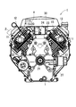
本発明は、図7,8に示されるインジェクタなどの燃料噴射装置を備えた空冷V型エンジンEに適用しても良い。図7,8に示す別実施形態のエンジンEにおいては、本実施形態のエンジンEと同じ機能を持つ箇所には同じ符号を付け、基本的にはその説明は省略するものとする。なお、図8においては、ファンケース43は、下部ファンケースのみを示し、上部ファンケースは省略してある。
[Another embodiment]
The present invention may be applied to an air-cooled V-type engine E equipped with a fuel injection device such as an injector shown in FIGS. In the engine E of another embodiment shown in FIGS. 7 and 8, the same reference numerals are given to portions having the same functions as those of the engine E of the present embodiment, and the description thereof is basically omitted. In FIG. 8, the fan case 43 shows only the lower fan case, and the upper fan case is omitted.

図7,8に示される空冷V型エンジンEは、クランクケース41とクランク軸42とファンケース43とエンジン冷却ファン44とを備えている。クランク軸42の架設方向を前後方向、前後方向の一方を前、他方を後として、ファンケース43はクランクケース41の前部に設けられ、クランク軸42の前端に取付けられるエンジン冷却ファン44は、ファンケース43内に収容されている。   The air-cooled V-type engine E shown in FIGS. 7 and 8 includes a crankcase 41, a crankshaft 42, a fan case 43, and an engine cooling fan 44. The fan case 43 is provided at the front part of the crankcase 41 with the installation direction of the crankshaft 42 being the front-rear direction, one of the front-rear directions is the front, and the other is the rear. The fan case 43 is accommodated.

クランク軸42の軸心Pの方向視においてクランクケース41から上方左右へV字形に突設される一対のシリンダ45,45、各シリンダ45,45の上端側(先端側)に取付けられるシリンダヘッド46,46、及びシリンダヘッド46,46の先端側に取付けられるシリンダヘッドカバー47,47を備えている。ファンケース43は、各シリンダ45,45及び各シリンダヘッド46,46を覆う大きさ及び形状に構成されており、エンジン冷却ファン44でエンジンを強制冷却することができる。   A pair of cylinders 45, 45 projecting in a V shape from the crankcase 41 upward and to the left and right as viewed in the direction of the axis P of the crankshaft 42, and a cylinder head 46 attached to the upper end side (tip side) of each cylinder 45, 45. , 46 and cylinder head covers 47, 47 attached to the tip side of the cylinder heads 46, 46. The fan case 43 has a size and shape that covers the cylinders 45 and 45 and the cylinder heads 46 and 46, and the engine cooling fan 44 can forcibly cool the engine.

左右のシリンダ45,45及びシリンダヘッド46,46の間の場所(空間部)である夾角プレース50に、スロットルボディ52が配置され、このスロットルボディ52から各シリンダヘッド46,46の吸気入口46a,46aに延びる左右の吸気マニホルド48,48が、先端下がりの傾斜が付けられた状態で設けられている。吸気マニホルド48,48はエンジン冷却ファン44の配置側である前側にあり、各シリンダヘッド46,46の排気出口(図示省略)は後側に設けられている。   A throttle body 52 is disposed in a depression place 50 which is a place (space part) between the left and right cylinders 45, 45 and the cylinder heads 46, 46. From the throttle body 52, intake ports 46a, Left and right intake manifolds 48, 48 extending to 46a are provided in a state where the tip is inclined downward. The intake manifolds 48, 48 are on the front side where the engine cooling fan 44 is disposed, and the exhaust outlets (not shown) of the cylinder heads 46, 46 are provided on the rear side.

燃料ポンプなどの燃料供給装置51からの供給燃料を各シリンダ45,45の(シリンダヘッド46,46の)吸気マニホルド48,48に分配して供給するための分配供給器49が、V字形を呈するシリンダどうしの間の場所である夾角プレース50を跨ぐ状態に配置されている。分配供給器49における左右一対の脚部49B,49Bは、各吸気マニホルド48のシリンダヘッド近傍箇所にインジェクタなどの燃料噴射装置53を介しての連通接続状態で連結されている。   A distribution supplier 49 for distributing and supplying fuel supplied from a fuel supply device 51 such as a fuel pump to the intake manifolds 48 and 48 of the cylinders 45 and 45 (cylinder heads 46 and 46) has a V shape. It is arranged in a state that straddles the depression place 50 that is a place between the cylinders. A pair of left and right leg portions 49B, 49B in the distribution supply device 49 are connected to a portion in the vicinity of the cylinder head of each intake manifold 48 in a communication connection state via a fuel injection device 53 such as an injector.

燃料供給装置51からの供給燃料は、分配供給器49を経て各燃料噴射装置53から各吸気マニホルド48,48に噴射され、吸気マニホルド48内を流れる空気と合流して混合気を形成しながら各シリンダヘッド46に送られるように構成されている。なお、分配供給器49には各イグニッションコイル54が載置支持されており、そのハイテンションコード55が各シリンダヘッド46に延びている。   The fuel supplied from the fuel supply device 51 is injected into the intake manifolds 48, 48 from the fuel injection devices 53 via the distribution supply devices 49, and merges with the air flowing in the intake manifold 48 to form air-fuel mixtures. It is configured to be sent to the cylinder head 46. In addition, each ignition coil 54 is placed and supported on the distribution supply device 49, and the high tension cord 55 extends to each cylinder head 46.

この別実施形態によるエンジンにおいては、オイル分離室4を備えるブリーザ装置Aやブリーザカバー20は、本実施形態によるエンジンEと相対的に同じ場所に装備されている。即ち、図7,8に示されるように、オイル分離室4やブリーザカバー20は、シリンダヘッド46における夾角プレース50側に存在している。   In the engine according to this alternative embodiment, the breather device A and the breather cover 20 including the oil separation chamber 4 are installed at the same location as the engine E according to this embodiment. That is, as shown in FIGS. 7 and 8, the oil separation chamber 4 and the breather cover 20 are present on the depression place 50 side of the cylinder head 46.

1 クランクケース
2 脈動圧作動器
3 エンジン機壁
4 オイル分離室
4A 分離本室
4B 分離後室
5 ガス入口孔
6 連通孔
7 連通パイプ
8 ガイド壁
9 オイル分離室内経路
15 分離室周壁
16 先端開口部
17 リード弁取付板
18 リード孔
19 リードバルブ
20 ブリーザカバー
24 吸気系(吸気管)
25 ガス出口
26 ブリーザパイプ
33 始端側の戻し孔
34 終端側の戻し孔
35 オイル捕捉促進具
k エンジン機内
DESCRIPTION OF SYMBOLS 1 Crankcase 2 Pulsation pressure actuator 3 Engine machine wall 4 Oil separation chamber 4A Separation main chamber 4B Separation rear chamber 5 Gas inlet hole 6 Communication hole 7 Communication pipe 8 Guide wall 9 Oil separation chamber path 15 Separation chamber peripheral wall 16 Tip opening 17 Reed valve mounting plate 18 Lead hole 19 Reed valve 20 Breather cover 24 Intake system (intake pipe)
25 Gas outlet 26 Breather pipe 33 Return hole on start side 34 Return hole on end side 35 Oil catching promotion tool k Inside the engine

Claims (6)

クランクケース内に生じたブローバイガスからオイル成分を分離して吸気系に還元するためのオイル分離室が、エンジン機壁の外側に前記エンジン機壁を用いて構成されているブリーザ装置付エンジンであって、
前記オイル分離室の始端側に、クランクケース内と連通しているエンジン機内に開口するガス入口孔が前記エンジン機壁に設けられるとともに、前記オイル分離室の終端側に、前記吸気系にブローバイガスを還元するためのガス出口が設けられ、
前記オイル分離室の始端側の前記ガス入口孔の近傍箇所、及び前記オイル分離室の終端側の前記ガス出口の近傍箇所のそれぞれにおける前記エンジン機壁に、前記オイル分離室において分離されたオイル成分を前記エンジン機内に戻すための戻し孔が設けられ、
前記始端側の戻し孔は、前記ガス入口孔に及ぶ手前においてブローバイガス中のオイル成分を捕捉するために前記エンジン機内に装備されたオイル捕捉促進具に臨む状態に形成され、かつ、前記終端側の戻し孔は直接前記エンジン機内に臨む状態に形成されているブリーザ装置付エンジン。
The oil separation chamber for separating the oil component from the blow-by gas generated in the crankcase and reducing it to the intake system is an engine with a breather device in which the engine machine wall is used outside the engine machine wall. And
A gas inlet hole that opens into the engine machine communicating with the inside of the crankcase is provided on the start side of the oil separation chamber in the engine machine wall, and blow-by gas is provided to the intake system on the terminal side of the oil separation chamber. A gas outlet is provided for reducing
The oil component separated in the oil separation chamber on the engine machine wall in each of the vicinity of the gas inlet hole on the start end side of the oil separation chamber and the vicinity of the gas outlet on the end side of the oil separation chamber Is provided with a return hole for returning to the engine machine,
The return hole on the start end side is formed in a state facing an oil capture promoting tool installed in the engine machine in order to capture the oil component in the blow-by gas before reaching the gas inlet hole, and the end side The engine with a breather device is formed so that the return hole directly faces the engine machine.
前記オイル分離室内にガイド壁を設け、このガイド壁でガス入口孔からガス出口までのオイル分離室内経路を蛇行させた構成とされている請求項1に記載のブリーザ装置付エンジン。   The engine with a breather device according to claim 1, wherein a guide wall is provided in the oil separation chamber, and the oil separation chamber path from the gas inlet hole to the gas outlet is meandered by the guide wall. 前記オイル分離室の分離室周壁と前記ガイド壁とが前記エンジン機壁に一体形成され、前記分離室周壁の先端開口部を覆って閉塞するブリーザカバーを設けて前記オイル分離室が構成されており、前記ブリーザカバーに前記ガス出口が設けられるとともに、前記吸気系である吸気管と前記ガス出口とを連通するブリーザパイプが装備されている請求項2に記載のブリーザ装置付エンジン。   A separation chamber peripheral wall of the oil separation chamber and the guide wall are integrally formed on the engine machine wall, and a breather cover that covers and closes a front end opening of the separation chamber peripheral wall is provided to constitute the oil separation chamber. The breather device-equipped engine according to claim 2, wherein the breather cover is provided with the gas outlet, and further provided with a breather pipe communicating the intake pipe as the intake system and the gas outlet. 前記先端開口部と前記ブリーザカバーとの間に、先端開口部の蓋となるリード弁取付板、及び前記リード弁取付板に形成されたリード孔を用いる状態で前記リード弁取付板に支持されるリードバルブを設けて、前記オイル分離室を、前記ガス入口孔側の分離本室と前記ガス出口側の分離後室とに仕切るとともに、
前記リードバルブは、前記分離本室の圧よりも前記分離後室の圧が低くなると開弁する一方弁に構成されている請求項3に記載のブリーザ装置付エンジン。
Between the tip opening and the breather cover, a reed valve mounting plate that serves as a lid for the tip opening and a lead hole formed in the reed valve mounting plate are used to support the lead valve mounting plate. A reed valve is provided to partition the oil separation chamber into a separation main chamber on the gas inlet hole side and a post-separation chamber on the gas outlet side,
4. The engine with a breather device according to claim 3, wherein the reed valve is configured as a one-way valve that is opened when a pressure in the post-separation chamber becomes lower than a pressure in the separation main chamber.
前記リード孔は、前記分離本室における蛇行された前記オイル分離室内経路の終端近傍に臨む位置に形成されている請求項4に記載のブリーザ装置付エンジン。   5. The engine with a breather device according to claim 4, wherein the lead hole is formed at a position facing a terminal end vicinity of the meandering oil separation chamber path in the separation main chamber. 前記分離室周壁に、前記オイル分離室内経路の後部又は終端近傍に臨む連通孔が形成され、前記連通孔に連通パイプを介して脈動圧作動器を連通させ、前記クランクケース内の脈動圧で前記脈動圧作動器が駆動される状態に構成されている請求項2〜5の何れか一項に記載のブリーザ装置付エンジン。   A communication hole facing the rear part or the vicinity of the terminal end of the oil separation chamber path is formed in the peripheral wall of the separation chamber, and a pulsation pressure actuator is connected to the communication hole via a communication pipe, and the pulsation pressure in the crankcase The engine with a breather device according to any one of claims 2 to 5, wherein the pulsation pressure actuator is configured to be driven.
JP2015253187A 2015-12-25 2015-12-25 Engine with breather device Active JP6475608B2 (en)

Priority Applications (1)

Application Number Priority Date Filing Date Title
JP2015253187A JP6475608B2 (en) 2015-12-25 2015-12-25 Engine with breather device

Applications Claiming Priority (1)

Application Number Priority Date Filing Date Title
JP2015253187A JP6475608B2 (en) 2015-12-25 2015-12-25 Engine with breather device

Publications (2)

Publication Number Publication Date
JP2017115748A true JP2017115748A (en) 2017-06-29
JP6475608B2 JP6475608B2 (en) 2019-02-27

Family

ID=59233677

Family Applications (1)

Application Number Title Priority Date Filing Date
JP2015253187A Active JP6475608B2 (en) 2015-12-25 2015-12-25 Engine with breather device

Country Status (1)

Country Link
JP (1) JP6475608B2 (en)

Citations (3)

* Cited by examiner, † Cited by third party
Publication number Priority date Publication date Assignee Title
JPS535635U (en) * 1976-07-02 1978-01-19
JP2006274882A (en) * 2005-03-29 2006-10-12 Kubota Corp Method of manufacturing engine
JP2012026321A (en) * 2010-07-21 2012-02-09 Nippon Soken Inc Oil mist treatment device

Patent Citations (3)

* Cited by examiner, † Cited by third party
Publication number Priority date Publication date Assignee Title
JPS535635U (en) * 1976-07-02 1978-01-19
JP2006274882A (en) * 2005-03-29 2006-10-12 Kubota Corp Method of manufacturing engine
JP2012026321A (en) * 2010-07-21 2012-02-09 Nippon Soken Inc Oil mist treatment device

Also Published As

Publication number Publication date
JP6475608B2 (en) 2019-02-27

Similar Documents

Publication Publication Date Title
JP6438917B2 (en) Breather device for internal combustion engine
JP5159550B2 (en) Blowby gas recirculation device for internal combustion engine
JP5478399B2 (en) Engine blow-by gas recirculation system
KR100672291B1 (en) Blow by gas ventilation device of internal combustion engine
JP5778009B2 (en) Internal combustion engine head cover structure
US20130008420A1 (en) Air-oil separator for extracting oil from engine blowby gas
JP4853481B2 (en) Intake device for internal combustion engine
JP2009203977A (en) Breather device for internal combustion engine
JP5478436B2 (en) Engine blow-by gas recirculation system
JP4573759B2 (en) Blow-by gas ventilation system for internal combustion engines
JP6475608B2 (en) Engine with breather device
JP4614203B2 (en) Positive crankcase ventilation system for internal combustion engines
US8413639B2 (en) Fuel supplying apparatus for internal combustion engine
JP6380035B2 (en) Internal combustion engine
JP6025582B2 (en) Intake manifold
JP4582003B2 (en) Blowby gas recirculation structure of internal combustion engine
JP2016188585A (en) Exhaust passage structure for internal combustion engine
JP2021099052A (en) Engine with ventilation device
JP7371534B2 (en) Blowby gas recirculation structure in engines
JP5478435B2 (en) Engine blow-by gas recirculation system
JP5874244B2 (en) Secondary air supply device for internal combustion engine
JP6319012B2 (en) Engine breather room layout structure
JP2015165141A (en) Secondary air supply device of internal combustion engine
JP2006274882A (en) Method of manufacturing engine
JP6166130B2 (en) Intake manifold for internal combustion engine

Legal Events

Date Code Title Description
A621 Written request for application examination

Free format text: JAPANESE INTERMEDIATE CODE: A621

Effective date: 20171222

A977 Report on retrieval

Free format text: JAPANESE INTERMEDIATE CODE: A971007

Effective date: 20180912

A131 Notification of reasons for refusal

Free format text: JAPANESE INTERMEDIATE CODE: A131

Effective date: 20180925

A521 Written amendment

Free format text: JAPANESE INTERMEDIATE CODE: A523

Effective date: 20181121

TRDD Decision of grant or rejection written
A01 Written decision to grant a patent or to grant a registration (utility model)

Free format text: JAPANESE INTERMEDIATE CODE: A01

Effective date: 20190115

A61 First payment of annual fees (during grant procedure)

Free format text: JAPANESE INTERMEDIATE CODE: A61

Effective date: 20190201

R150 Certificate of patent or registration of utility model

Ref document number: 6475608

Country of ref document: JP

Free format text: JAPANESE INTERMEDIATE CODE: R150