JP2017113802A - Manufacturing method of helical gear - Google Patents
Manufacturing method of helical gear Download PDFInfo
- Publication number
- JP2017113802A JP2017113802A JP2015257856A JP2015257856A JP2017113802A JP 2017113802 A JP2017113802 A JP 2017113802A JP 2015257856 A JP2015257856 A JP 2015257856A JP 2015257856 A JP2015257856 A JP 2015257856A JP 2017113802 A JP2017113802 A JP 2017113802A
- Authority
- JP
- Japan
- Prior art keywords
- tooth profile
- manufacturing
- helical gear
- forging
- die
- Prior art date
- Legal status (The legal status is an assumption and is not a legal conclusion. Google has not performed a legal analysis and makes no representation as to the accuracy of the status listed.)
- Pending
Links
Images


Abstract
Description
本発明は、自動車などに使用される、ヘリカルギヤの製造方法に関するものである。 The present invention relates to a method for manufacturing a helical gear used in an automobile or the like.
従来、ヘリカルギヤを製造する手段として、多くの場合、全ての加工において切削加工が行われていた。切削加工は鍛造加工に比べ、材料の歩留まりが悪いことから、鍛造加工によって完成品のヘリカルギヤに近い形状に一旦加工し、そこから切削加工によって仕上げる方法が採られる場合があった。この方法によれば、材料の歩留まりを改善することが可能となる。 Conventionally, as a means for manufacturing a helical gear, in many cases, cutting has been performed in all processing. Since cutting has a lower material yield than forging, there is a case in which a method of once processing into a shape close to a helical gear of a finished product by forging and then finishing by cutting is used in some cases. According to this method, the yield of the material can be improved.
鍛造加工のうち、冷間鍛造によってヘリカルギヤを製造することで、完成形に近付けることが可能となり、仕上げの切削加工の量を少なくすることが可能である。しかし、冷間鍛造によってヘリカルギヤを製造する場合、ねじれた歯形を成形するため、金型から取り出す際に過大な荷重がかかることによって、歯形の精度が低下してしまっていた。 By manufacturing the helical gear by cold forging among the forging processes, it becomes possible to approach the finished shape, and the amount of finishing cutting can be reduced. However, when a helical gear is manufactured by cold forging, a twisted tooth profile is formed, so that an excessive load is applied when taking out from the mold, and the accuracy of the tooth profile is lowered.
本発明は上述のような課題を解決するためになされたもので、鍛造加工によるヘリカルギヤの製造において、歯形の精度を向上することが可能な製造方法を提供するものである。 The present invention has been made to solve the above-described problems, and provides a manufacturing method capable of improving the accuracy of a tooth profile in manufacturing a helical gear by forging.
本発明に係る製造方法においては、歯形加工前のブランクを予め加熱した後に鍛造を行うことで歯形を加工し、成形品を歯形ダイ内で冷却した後に、前記歯形ダイから取り出すことを特徴とするヘリカルギヤの製造方法である。 In the manufacturing method according to the present invention, the blank before the tooth profile processing is preheated and then the forging is performed by forging, and the molded product is cooled in the tooth profile die and then taken out from the tooth profile die. It is a manufacturing method of a helical gear.
本発明によれば、加工後に金型から取り出す際に必要な荷重が低減されることによって歯形の精度を向上することが可能となる。更に、加工時に必要な荷重が低減することで金型への負担が低減するため、金型寿命の改善も期待できる。 According to the present invention, it is possible to improve the accuracy of the tooth profile by reducing the load required when removing from the mold after processing. In addition, since the load on the mold is reduced by reducing the load required at the time of processing, improvement of the mold life can be expected.
以下に本発明の実施例について示す。図1は本発明の実施例の流れを示した図である。各項目について順次説明する。 Examples of the present invention will be described below. FIG. 1 is a diagram showing the flow of an embodiment of the present invention. Each item will be described in turn.
<ブランク作成>
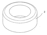
図2に示すブランク2を作成する。ブランク2の作成方法は鍛造加工、切削加工のどちらであっても構わない。前者は材料の歩留まりが良いものの、要求される精度が高くなるにつれて対応困難となる。後者は材料の歩留まりが良くないものの、要求される精度がある程度高くなっても対応可能である。両者には一長一短あるため、状況に応じて使い分けることが望ましい。<Blank creation>
A blank 2 shown in FIG. 2 is created. The method for creating the blank 2 may be either forging or cutting. The former has a good material yield, but becomes difficult to handle as the required accuracy increases. Although the latter does not have a good material yield, it can be used even if the required accuracy is increased to some extent. Since both have advantages and disadvantages, it is desirable to use them properly according to the situation.
<加熱>
ブランク2を加熱する。加熱する目的は、歯形を鍛造により加工する際の荷重を低減することと、成形品を金型から取り出す際、部材の冷却による収縮によって加工された歯形への抵抗を低減することである。加熱による効果と冷却による効果を効率良く得るため、加熱温度は50〜350℃とすることが望ましい。加熱温度が高過ぎる場合、酸化皮膜が形成され、歯形精度が低下するおそれがある。<Heating>
The blank 2 is heated. The purpose of heating is to reduce the load when the tooth profile is processed by forging, and to reduce the resistance to the processed tooth profile by contraction due to cooling of the member when the molded product is taken out from the mold. In order to efficiently obtain the effect of heating and the effect of cooling, the heating temperature is preferably 50 to 350 ° C. When the heating temperature is too high, an oxide film is formed, and the tooth profile accuracy may be lowered.
<歯形加工>
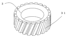
加熱後のブランク2を鍛造によって加工し、図3に示す成形品3を成形する。図4(a)、(b)は、歯形加工に使用する金型の主要部を模式化したものであり、内パンチ41、外パンチ42、マンドレル43、歯形ダイ44、下型45で構成されている。金型を保持し、加圧を行うプレス加工機(図示省略)は、加圧荷重が可変であるもの、例えば油圧サーボ式のものを使用する。プレス加工機の加圧荷重が可変でない場合、例えばリンクプレス式等の場合、所定の荷重が一度に作用してしまうため、本実施例の鍛造方法を採用することは不可能となる(詳細な理由は後述する)。内パンチ41及び外パンチ42と下型45でワーク46を挟んで加圧することにより、ワーク46を歯形ダイ44に沿って変形させ、所定の形態に加工する。マンドレル43はワーク46の内径穴を貫通しており、加工時に内径穴の精度を保つ役割を果たす。本実施例における金型の特徴は、可動側であるパンチが内パンチ41と外パンチ42に分かれており、別々の動作が可能な点である。<Tooth profile processing>
The blank 2 after heating is processed by forging to form a molded
図4(a)は予備据え込みまでの状態を、図4(b)は予備据え込みの後、分流成形を行っている状態を示している。1サイクルの加圧動作の中で、予備据え込みと分流成形の2つを行う。予備据え込みにおいては、図4(a)中の矢印で示すように、内パンチ41と外パンチ42は同時に下降することで、ワーク46を加圧する。分流成形においては、図4(b)中の矢印で示すように、外パンチ42の荷重を維持したまま、内パンチ41の荷重が開放されることによって行われる。加工されたワーク46は、歯形ダイ44内で冷却された後に取り出される。なお、加工時に生じる熱によるワーク46の歪みは加工速度(発熱量)に比例することから、加工精度を高めるためには、ワーク46を鍛造する際の荷重は衝撃的ではなく、漸次増大することが必要である。上記の理由により、加圧速度は5〜10mm/secとすることが望ましい。 FIG. 4 (a) shows a state up to preliminary upsetting, and FIG. 4 (b) shows a state in which shunt forming is performed after preliminary upsetting. In one cycle of pressurizing operation, pre-upsetting and split flow forming are performed. In the preliminary upsetting, as indicated by an arrow in FIG. 4A, the inner punch 41 and the outer punch 42 are simultaneously lowered to pressurize the work 46. As shown by the arrow in FIG. 4B, the flow dividing molding is performed by releasing the load of the inner punch 41 while maintaining the load of the outer punch 42. The processed workpiece 46 is taken out after being cooled in the tooth profile die 44. Since the distortion of the workpiece 46 due to heat generated during machining is proportional to the machining speed (heat generation amount), in order to increase the machining accuracy, the load when forging the workpiece 46 is not shocking but gradually increases. is necessary. For the above reason, it is desirable that the pressurization speed is 5 to 10 mm / sec.
分流成形を行わず、据え込み加工のみでワーク46を歯形ダイ44に充満させることにより歯形31の成形を試みると、歯形ダイ44に作用する荷重の急激な増加により、成形途中で歯形ダイ44が破損してしまう。これに対し、分流成形を行うことで、加工に必要な荷重が低減され、加工精度の向上や金型寿命の改善が可能となる。 If the forming of the tooth profile 31 is attempted by filling the tooth profile die 44 with the workpiece 46 only by upsetting without split flow forming, the tooth profile die 44 is formed during the formation due to a sudden increase in the load acting on the tooth profile die 44. It will be damaged. On the other hand, by performing shunt forming, the load required for processing is reduced, and processing accuracy can be improved and the mold life can be improved.
歯形加工後のワーク46を歯形ダイ44から取り出す際の速度が大きい程、衝撃的な負荷の影響や発熱量が大きくなり、歯形への負荷が大きくなってしまうことから、歯形加工後の部材を歯形ダイ44から取り出す際の速度は20〜50mm/secとすることが望ましい。また、成形品の熱収縮量を制御するため、加熱時の温度と冷却後(成形品取り出し時)の温度の差は20〜200℃であることが望ましい。 The greater the speed at which the workpiece 46 after the tooth profile processing is taken out from the tooth profile die 44, the greater the impact of the impact load and the amount of heat generated and the greater the load on the tooth profile. The speed at the time of taking out from the tooth profile die 44 is desirably 20 to 50 mm / sec. In order to control the amount of heat shrinkage of the molded product, the difference between the temperature during heating and the temperature after cooling (when taking out the molded product) is preferably 20 to 200 ° C.
2 ブランク
3 成形品
31 歯形
41 内パンチ
42 外パンチ
43 マンドレル
44 歯形ダイ
45 下型
46 ワーク2 Blank 3 Molded product 31 Tooth profile 41 Internal punch 42 External punch 43 Mandrel 44 Tooth profile die 45 Lower mold 46 Workpiece
Claims (5)
Priority Applications (1)
| Application Number | Priority Date | Filing Date | Title |
|---|---|---|---|
| JP2015257856A JP2017113802A (en) | 2015-12-24 | 2015-12-24 | Manufacturing method of helical gear |
Applications Claiming Priority (1)
| Application Number | Priority Date | Filing Date | Title |
|---|---|---|---|
| JP2015257856A JP2017113802A (en) | 2015-12-24 | 2015-12-24 | Manufacturing method of helical gear |
Publications (1)
| Publication Number | Publication Date |
|---|---|
| JP2017113802A true JP2017113802A (en) | 2017-06-29 |
Family
ID=59231361
Family Applications (1)
| Application Number | Title | Priority Date | Filing Date |
|---|---|---|---|
| JP2015257856A Pending JP2017113802A (en) | 2015-12-24 | 2015-12-24 | Manufacturing method of helical gear |
Country Status (1)
| Country | Link |
|---|---|
| JP (1) | JP2017113802A (en) |
Cited By (1)
| Publication number | Priority date | Publication date | Assignee | Title |
|---|---|---|---|---|
| CN116532508A (en) * | 2023-03-17 | 2023-08-04 | 山东普瑞而机械制造有限公司 | Gear or gear ring high-temperature extrusion finish machining manufacturing method |
-
2015
- 2015-12-24 JP JP2015257856A patent/JP2017113802A/en active Pending
Cited By (1)
| Publication number | Priority date | Publication date | Assignee | Title |
|---|---|---|---|---|
| CN116532508A (en) * | 2023-03-17 | 2023-08-04 | 山东普瑞而机械制造有限公司 | Gear or gear ring high-temperature extrusion finish machining manufacturing method |
Similar Documents
| Publication | Publication Date | Title |
|---|---|---|
| CN104493061B (en) | Cold-forging technology for safety belt transmission shaft and die structure of molded transmission patterned tooth | |
| CN104607580A (en) | Forging forming technology of aluminum alloy straight-flanked ring with extra-large specification | |
| TW201620639A (en) | A method for making a spanner | |
| KR101456457B1 (en) | A wheel manufacturing method which uses a gravity casting and multi stage flow forming | |
| TWI361117B (en) | ||
| CN105665608A (en) | Forging technique for nuclear-grade F91 valve body | |
| CN102527895B (en) | Process and die for forging big circular ring with rectangular section | |
| US20140238099A1 (en) | Process for Making Forged and Machined Components | |
| CN103567338A (en) | Metal element manufacturing method | |
| KR20150088688A (en) | Method of manufacturing gear with double teeth patterns involving forging and two stage cold extrusion process | |
| CN108326216A (en) | A kind of thin pieces forging technology of golf iron head | |
| CN103419002A (en) | Temperature cooling precision forming method of big modulus high boss bevel gear | |
| JP2019531897A5 (en) | ||
| TW201323109A (en) | Method for manufacturing magnesium alloy | |
| CN102179464B (en) | Process for forming generator claw pole of vehicle | |
| JP2017113802A (en) | Manufacturing method of helical gear | |
| JP2017164755A (en) | Manufacturing method for press-molded article and press-molded article | |
| US20170072455A1 (en) | Burr-freebolt forging mould | |
| TWI647048B (en) | Method for forming a spanner | |
| CN203711731U (en) | Closed extrusion finish forging forming die for cam shaft | |
| JP2019512046A (en) | Method of manufacturing bar from titanium alloy | |
| CN107717352A (en) | A kind of moulding process of the forging with decile rectangular end face tooth | |
| JP6605006B2 (en) | Forging method | |
| CN106363363A (en) | Semi-solid thixo-forging forming technology for steel impeller | |
| CN204262260U (en) | The mould structure of safety belt transmission shaft driven flower tooth |