JP2017111663A - Road information detection apparatus, driving support apparatus, road information detection system, road information detection method, driving control method, and program - Google Patents
Road information detection apparatus, driving support apparatus, road information detection system, road information detection method, driving control method, and program Download PDFInfo
- Publication number
- JP2017111663A JP2017111663A JP2015246388A JP2015246388A JP2017111663A JP 2017111663 A JP2017111663 A JP 2017111663A JP 2015246388 A JP2015246388 A JP 2015246388A JP 2015246388 A JP2015246388 A JP 2015246388A JP 2017111663 A JP2017111663 A JP 2017111663A
- Authority
- JP
- Japan
- Prior art keywords
- road
- start position
- curve
- attachment
- information
- Prior art date
- Legal status (The legal status is an assumption and is not a legal conclusion. Google has not performed a legal analysis and makes no representation as to the accuracy of the status listed.)
- Granted
Links
Images


Classifications
-
- B—PERFORMING OPERATIONS; TRANSPORTING
- B60—VEHICLES IN GENERAL
- B60W—CONJOINT CONTROL OF VEHICLE SUB-UNITS OF DIFFERENT TYPE OR DIFFERENT FUNCTION; CONTROL SYSTEMS SPECIALLY ADAPTED FOR HYBRID VEHICLES; ROAD VEHICLE DRIVE CONTROL SYSTEMS FOR PURPOSES NOT RELATED TO THE CONTROL OF A PARTICULAR SUB-UNIT
- B60W40/00—Estimation or calculation of non-directly measurable driving parameters for road vehicle drive control systems not related to the control of a particular sub unit, e.g. by using mathematical models
- B60W40/02—Estimation or calculation of non-directly measurable driving parameters for road vehicle drive control systems not related to the control of a particular sub unit, e.g. by using mathematical models related to ambient conditions
- B60W40/06—Road conditions
- B60W40/072—Curvature of the road
-
- G—PHYSICS
- G08—SIGNALLING
- G08G—TRAFFIC CONTROL SYSTEMS
- G08G1/00—Traffic control systems for road vehicles
- G08G1/09—Arrangements for giving variable traffic instructions
- G08G1/0962—Arrangements for giving variable traffic instructions having an indicator mounted inside the vehicle, e.g. giving voice messages
- G08G1/09623—Systems involving the acquisition of information from passive traffic signs by means mounted on the vehicle
-
- B—PERFORMING OPERATIONS; TRANSPORTING
- B60—VEHICLES IN GENERAL
- B60W—CONJOINT CONTROL OF VEHICLE SUB-UNITS OF DIFFERENT TYPE OR DIFFERENT FUNCTION; CONTROL SYSTEMS SPECIALLY ADAPTED FOR HYBRID VEHICLES; ROAD VEHICLE DRIVE CONTROL SYSTEMS FOR PURPOSES NOT RELATED TO THE CONTROL OF A PARTICULAR SUB-UNIT
- B60W40/00—Estimation or calculation of non-directly measurable driving parameters for road vehicle drive control systems not related to the control of a particular sub unit, e.g. by using mathematical models
- B60W40/02—Estimation or calculation of non-directly measurable driving parameters for road vehicle drive control systems not related to the control of a particular sub unit, e.g. by using mathematical models related to ambient conditions
- B60W40/06—Road conditions
-
- G—PHYSICS
- G05—CONTROLLING; REGULATING
- G05D—SYSTEMS FOR CONTROLLING OR REGULATING NON-ELECTRIC VARIABLES
- G05D1/00—Control of position, course, altitude or attitude of land, water, air or space vehicles, e.g. using automatic pilots
- G05D1/02—Control of position or course in two dimensions
- G05D1/021—Control of position or course in two dimensions specially adapted to land vehicles
- G05D1/0231—Control of position or course in two dimensions specially adapted to land vehicles using optical position detecting means
- G05D1/0246—Control of position or course in two dimensions specially adapted to land vehicles using optical position detecting means using a video camera in combination with image processing means
-
- G—PHYSICS
- G05—CONTROLLING; REGULATING
- G05D—SYSTEMS FOR CONTROLLING OR REGULATING NON-ELECTRIC VARIABLES
- G05D1/00—Control of position, course, altitude or attitude of land, water, air or space vehicles, e.g. using automatic pilots
- G05D1/02—Control of position or course in two dimensions
- G05D1/021—Control of position or course in two dimensions specially adapted to land vehicles
- G05D1/0268—Control of position or course in two dimensions specially adapted to land vehicles using internal positioning means
- G05D1/0272—Control of position or course in two dimensions specially adapted to land vehicles using internal positioning means comprising means for registering the travel distance, e.g. revolutions of wheels
-
- G—PHYSICS
- G05—CONTROLLING; REGULATING
- G05D—SYSTEMS FOR CONTROLLING OR REGULATING NON-ELECTRIC VARIABLES
- G05D1/00—Control of position, course, altitude or attitude of land, water, air or space vehicles, e.g. using automatic pilots
- G05D1/02—Control of position or course in two dimensions
- G05D1/021—Control of position or course in two dimensions specially adapted to land vehicles
- G05D1/0276—Control of position or course in two dimensions specially adapted to land vehicles using signals provided by a source external to the vehicle
- G05D1/0278—Control of position or course in two dimensions specially adapted to land vehicles using signals provided by a source external to the vehicle using satellite positioning signals, e.g. GPS
-
- G—PHYSICS
- G06—COMPUTING OR CALCULATING; COUNTING
- G06V—IMAGE OR VIDEO RECOGNITION OR UNDERSTANDING
- G06V20/00—Scenes; Scene-specific elements
- G06V20/50—Context or environment of the image
- G06V20/56—Context or environment of the image exterior to a vehicle by using sensors mounted on the vehicle
- G06V20/588—Recognition of the road, e.g. of lane markings; Recognition of the vehicle driving pattern in relation to the road
-
- G—PHYSICS
- G08—SIGNALLING
- G08G—TRAFFIC CONTROL SYSTEMS
- G08G1/00—Traffic control systems for road vehicles
-
- G—PHYSICS
- G08—SIGNALLING
- G08G—TRAFFIC CONTROL SYSTEMS
- G08G1/00—Traffic control systems for road vehicles
- G08G1/09—Arrangements for giving variable traffic instructions
-
- G—PHYSICS
- G08—SIGNALLING
- G08G—TRAFFIC CONTROL SYSTEMS
- G08G1/00—Traffic control systems for road vehicles
- G08G1/16—Anti-collision systems
-
- G—PHYSICS
- G09—EDUCATION; CRYPTOGRAPHY; DISPLAY; ADVERTISING; SEALS
- G09B—EDUCATIONAL OR DEMONSTRATION APPLIANCES; APPLIANCES FOR TEACHING, OR COMMUNICATING WITH, THE BLIND, DEAF OR MUTE; MODELS; PLANETARIA; GLOBES; MAPS; DIAGRAMS
- G09B29/00—Maps; Plans; Charts; Diagrams, e.g. route diagram
- G09B29/10—Map spot or coordinate position indicators; Map reading aids
Landscapes
- Engineering & Computer Science (AREA)
- Physics & Mathematics (AREA)
- General Physics & Mathematics (AREA)
- Automation & Control Theory (AREA)
- Mathematical Physics (AREA)
- Theoretical Computer Science (AREA)
- Remote Sensing (AREA)
- Radar, Positioning & Navigation (AREA)
- Aviation & Aerospace Engineering (AREA)
- Mechanical Engineering (AREA)
- Transportation (AREA)
- Business, Economics & Management (AREA)
- Multimedia (AREA)
- Educational Administration (AREA)
- Educational Technology (AREA)
- Computer Vision & Pattern Recognition (AREA)
- Electromagnetism (AREA)
- Traffic Control Systems (AREA)
- Game Theory and Decision Science (AREA)
- Medical Informatics (AREA)
- Evolutionary Computation (AREA)
- Artificial Intelligence (AREA)
- Health & Medical Sciences (AREA)
- Navigation (AREA)
- Control Of Driving Devices And Active Controlling Of Vehicle (AREA)
- Instructional Devices (AREA)
Abstract
【課題】道路において、坂道やカーブの正確な開始位置を特定することができる道路情報検出装置を提供する。【解決手段】道路情報検出装置10は、曲線開始位置特定部103を備える。前記曲線開始位置特定部は、画像を取得する画像情報取得部101と、前記画像に映る前記付設物の識別情報を検出する付設物検出部102と、を備え、道路上の付設物の検出に基づいて前記道路の構造における緩和曲線の開始位置を特定する。さらに、前記曲線開始位置特定部から前記開始位置を取得し、前記開始位置に基づいて制動制御を行う運転制御部と、を備える。【選択図】図2A road information detecting device is provided that can specify an accurate start position of a slope or a curve on a road. A road information detection apparatus includes a curve start position specifying unit. The curve start position specifying unit includes an image information acquisition unit 101 that acquires an image, and an attachment detection unit 102 that detects identification information of the attachment reflected in the image, and detects an attachment on a road. Based on this, the start position of the relaxation curve in the road structure is specified. Furthermore, the driving | operation control part which acquires the said starting position from the said curve starting position specific | specification part, and performs braking control based on the said starting position is provided. [Selection] Figure 2
Description
本発明は、道路情報検出装置、運転支援装置、道路情報検出システム、道路情報検出方法、運転制御方法及びプログラムに関する。 The present invention relates to a road information detection device, a driving support device, a road information detection system, a road information detection method, a driving control method, and a program.
道路において車両が安全かつ快適に走行するためには、道路における車両の位置を検出すると共に、坂道やカーブなどの開始位置を正確に検出し、道路の構造に応じて車両が走行する必要がある。
特許文献1には、関連する技術として、車両の位置を検出するナビゲーション装置と勾配情報を有した地図情報とに基づいて、車両の進路上の所定距離内に坂道が存在すると判定した場合に、坂道の勾配に応じた燃料の噴射で車両を走行させる技術が開示されている。
特許文献2には、関連する技術として、車両が交差点の近傍で進入しようとしている道路の形状等の情報を車載通信機を介して取得する技術が開示されている。
特許文献3には、関連する技術として、道路全体を複数に分解し、分解したそれぞれの道路の形状をモデル化することにより、道路全体をモデル化しデータベースに記録する技術が開示されている。
特許文献4には、関連する技術として、車載カメラで取得した画像情報に基づいて特定の道路施設の位置を検出した場合、車両の検出位置を補正する技術が開示されている。
In order for a vehicle to travel safely and comfortably on a road, it is necessary to detect the position of the vehicle on the road and accurately detect the starting position of a slope or a curve, and the vehicle must travel according to the structure of the road. .
In
Japanese Patent Application Laid-Open No. 2004-228561 discloses a related technique in which an entire road is modeled and recorded in a database by decomposing the entire road into a plurality of parts and modeling the shape of each decomposed road.
ところで、道路における坂道やカーブの開始位置を検出する方法の1つとして地図情報を用いることが考えらえる。しかしながら、地図中に道路における坂道やカーブの構造と正確な位置をすべて含めることは膨大な時間と手間が掛かり大変困難である。
そのため、道路において、坂道やカーブの正確な開始位置を簡易的に特定することのできる技術が求められていた。
By the way, it is conceivable to use map information as one of the methods for detecting the starting position of a slope or a curve on a road. However, it is very difficult to include all the structures and exact positions of slopes and curves on the road in the map because it takes a lot of time and effort.
Therefore, there has been a demand for a technique that can easily specify an accurate start position of a slope or a curve on a road.
本発明は、上記の課題を解決することのできる道路情報検出装置、運転支援装置、道路情報検出システム、道路情報検出方法、運転制御方法及びプログラムを提供することを目的としている。 An object of the present invention is to provide a road information detection device, a driving support device, a road information detection system, a road information detection method, a driving control method, and a program that can solve the above-described problems.
上記目的を達成するために、本発明は、道路上の付設物の検出に基づいて前記道路の構造における緩和曲線の開始位置を特定する曲線開始位置特定部、を備える道路情報検出装置である。 In order to achieve the above object, the present invention is a road information detection device including a curve start position specifying unit that specifies a start position of a relaxation curve in the structure of the road based on detection of an accessory on the road.
また、本発明は、道路上の付設物の検出に基づいて前記道路の構造における緩和曲線の開始位置を特定する曲線開始位置特定部を備える道路情報検出装置から前記開始位置を取得する開始位置取得部と、前記開始位置に基づいて加速制御または制動制御または進行方向変更制御を行う運転制御部と、を備える運転支援装置である。 In addition, the present invention provides a start position acquisition for acquiring the start position from a road information detection device including a curve start position specifying unit that specifies a start position of a relaxation curve in the structure of the road based on detection of an accessory on the road. And a driving control unit that performs acceleration control, braking control, or traveling direction change control based on the start position.
また、本発明は、道路上の付設物の検出に基づいて前記道路の構造における緩和曲線の開始位置を特定する曲線開始位置特定部を備える道路情報検出装置から前記開始位置を取得する開始位置取得部と、前記開始位置に基づいて制動制御を行う運転制御部と、を備える運転支援装置である。 In addition, the present invention provides a start position acquisition for acquiring the start position from a road information detection device including a curve start position specifying unit that specifies a start position of a relaxation curve in the structure of the road based on detection of an accessory on the road. And a driving control unit that performs braking control based on the start position.
また、本発明は、道路上の付設物の検出に基づいて前記道路の構造における緩和曲線の開始位置を特定する曲線開始位置特定部を備える道路情報検出装置から前記開始位置を取得する開始位置取得部と、前記開始位置に基づいて進行方向変更制御を行う運転制御部と、を備える運転支援装置である。 In addition, the present invention provides a start position acquisition for acquiring the start position from a road information detection device including a curve start position specifying unit that specifies a start position of a relaxation curve in the structure of the road based on detection of an accessory on the road. And a driving control unit that performs traveling direction change control based on the start position.
また、本発明は、道路上の付設物に関する識別情報、前記付設物に関する位置情報、前記位置情報と道路の構造における緩和曲線の開始位置との関係を示す情報を少なくとも含む道路情報を配信する道路情報配信システムと、検出した道路上の付設物の位置情報と前記道路情報とに基づいて前記道路の構造における緩和曲線の開始位置を特定する曲線開始位置特定部を備える道路情報検出装置と、を備える道路情報検出システムである。 Further, the present invention provides a road for delivering road information including at least identification information relating to an accessory on the road, position information relating to the accessory, and information indicating a relationship between the position information and a start position of a relaxation curve in the road structure. An information distribution system; and a road information detection device including a curve start position specifying unit that specifies a start position of a relaxation curve in the structure of the road based on the detected position information of the accessory on the road and the road information. A road information detection system provided.
また、本発明は、道路上の付設物の検出に基づいて前記道路の構造における緩和曲線の開始位置を特定すること、を含む道路情報検出装置の道路情報検出方法である。 Moreover, this invention is a road information detection method of the road information detection apparatus including specifying the starting position of the relaxation curve in the structure of the said road based on the detection of the attachment on a road.
また、本発明は、道路上の付設物の検出に基づいて前記道路の構造における緩和曲線の開始位置を特定する曲線開始位置特定部を備える道路情報検出装置から前記開始位置を取得すること、前記開始位置に基づいて加速制御または制動制御または進行方向変更制御を行うこと、を含む運転支援装置の運転制御方法である。 Further, the present invention obtains the start position from a road information detection device comprising a curve start position specifying unit that specifies a start position of a relaxation curve in the structure of the road based on detection of an accessory on the road, A driving control method for a driving support device, including performing acceleration control, braking control, or traveling direction change control based on a start position.
また、本発明は、道路上の付設物の検出に基づいて前記道路の構造における緩和曲線の開始位置を特定する曲線開始位置特定部を備える道路情報検出装置から前記開始位置を取得すること、前記開始位置に基づいて制動制御を行うこと、を含む運転支援装置の運転制御方法である。 Further, the present invention obtains the start position from a road information detection device comprising a curve start position specifying unit that specifies a start position of a relaxation curve in the structure of the road based on detection of an accessory on the road, A driving control method for a driving support device, including performing braking control based on a start position.
また、本発明は、道路上の付設物の検出に基づいて前記道路の構造における緩和曲線の開始位置を特定する曲線開始位置特定部を備える道路情報検出装置から前記開始位置を取得すること、前記開始位置に基づいて進行方向変更制御を行うこと、を含む運転支援装置の運転制御方法である。 Further, the present invention obtains the start position from a road information detection device comprising a curve start position specifying unit that specifies a start position of a relaxation curve in the structure of the road based on detection of an accessory on the road, A driving control method for a driving support device, including performing a direction change control based on a start position.
また、本発明は、道路上の付設物に関する識別情報、前記付設物に関する位置情報、前記位置情報と道路の構造における緩和曲線の開始位置との関係を示す情報を少なくとも含む道路情報を配信すること、検出した道路上の付設物の位置情報と前記道路情報とに基づいて前記道路の構造における緩和曲線の開始位置を特定すること、を含む道路情報検出システムの道路情報検出方法である。 Further, the present invention delivers road information including at least identification information relating to an accessory on a road, position information relating to the accessory, and information indicating a relationship between the position information and a start position of a relaxation curve in a road structure. A road information detection method for a road information detection system, comprising: specifying a start position of a relaxation curve in the structure of the road based on the detected position information of the accessory on the road and the road information.
また、本発明は、コンピュータに、道路上の付設物の検出に基づいて前記道路の構造における緩和曲線の開始位置を特定すること、を実行させるプログラムである。 The present invention is a program for causing a computer to specify a start position of a relaxation curve in the structure of the road based on detection of an accessory on the road.
また、本発明は、コンピュータに、道路上の付設物の検出に基づいて前記道路の構造における緩和曲線の開始位置を特定する曲線開始位置特定部を備える道路情報検出装置から前記開始位置を取得すること、前記開始位置に基づいて加速制御または制動制御または進行方向変更制御を行うこと、を実行させるプログラムである。 According to another aspect of the present invention, the computer acquires the start position from a road information detection device including a curve start position specifying unit that specifies a start position of a relaxation curve in the road structure based on detection of an accessory on the road. This is a program for executing acceleration control, braking control, or traveling direction change control based on the start position.
また、本発明は、コンピュータに、道路上の付設物の検出に基づいて前記道路の構造における緩和曲線の開始位置を特定する曲線開始位置特定部を備える道路情報検出装置から前記開始位置を取得すること、前記開始位置に基づいて制動制御を行うこと、を実行させるプログラムである。 According to another aspect of the present invention, the computer acquires the start position from a road information detection device including a curve start position specifying unit that specifies a start position of a relaxation curve in the road structure based on detection of an accessory on the road. This is a program for executing braking control based on the start position.
また、本発明は、コンピュータに、道路上の付設物の検出に基づいて前記道路の構造における緩和曲線の開始位置を特定する曲線開始位置特定部を備える道路情報検出装置から前記開始位置を取得すること、前記開始位置に基づいて進行方向変更制御を行うこと、を実行させるプログラムである。 According to another aspect of the present invention, the computer acquires the start position from a road information detection device including a curve start position specifying unit that specifies a start position of a relaxation curve in the road structure based on detection of an accessory on the road. This is a program for executing the direction change control based on the start position.
本発明によれば、道路において、坂道やカーブの正確な開始位置を簡易的に特定することができる。 According to the present invention, it is possible to easily specify an accurate start position of a slope or a curve on a road.
<第一の実施形態>
本発明の第一の実施形態による道路情報検出装置について説明する。
本発明の第一の実施形態による道路情報検出装置は、本発明の最小構成の道路情報検出装置である。
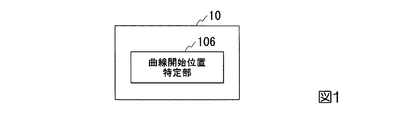
本発明の第一の実施形態による道路情報検出装置10は、図1に示すように、少なくとも、曲線開始位置特定部103を備える。
<First embodiment>
A road information detection apparatus according to a first embodiment of the present invention will be described.
The road information detection apparatus according to the first embodiment of the present invention is the road information detection apparatus having the minimum configuration according to the present invention.
The road
曲線開始位置特定部103は、道路上の付設物の検出に基づいて道路の構造における緩和曲線の開始位置を特定する。道路上の付設物は、例えば、道路標識、距離標(キロポスト)、ETC(Electronic Toll Collection system)ガントリーなどである。緩和曲線は、車両が道路における直線部と円弧部とを滑らかにつなぐために直線部と円弧部との間に入れる曲線である。緩和曲線の開始位置は、例えば、坂道の開始位置、カーブの開始位置である。
具体的には、例えば、曲線開始位置特定部103は、道路標識の位置を特定する。曲線開始位置特定部103は、特定した道路標識の位置と、その位置から緩和曲線の開始位置までの距離との対応関係を示す情報を用いて、緩和曲線の開始位置を特定する。
The curve start
Specifically, for example, the curve start
このようにすれば、道路情報検出装置10は、道路において、坂道やカーブの正確な開始位置を簡易的に特定することができる。
In this way, the road
<第二の実施形態>
本発明の第二の実施形態による道路情報検出装置について説明する。
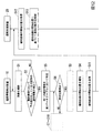
本発明の第二の実施形態による道路情報検出装置10は、図2に示すように、画像情報取得部101と、付設物検出部102と、曲線開始位置特定部103と、記憶部104と、報知部105と、を備える。
<Second Embodiment>
A road information detection apparatus according to a second embodiment of the present invention will be described.
As shown in FIG. 2, the road
画像情報取得部101は、画像を取得する。画像情報取得部101は、例えば、カメラである。
The image
付設物検出部102は、画像情報取得部101が取得した画像に映る付設物の識別情報を検出する。付設物の識別情報は、付設物が道路標識である場合、例えば、速度制限80km/hを示す標識の中の“80”という文字である。また、付設物の識別情報は、付設物が距離標である場合、例えば、各高速道路の起点からの距離を示す距離標の中の“114.7”という文字である。また、付設物の識別情報は、例えば、付設物がETCガントリーである場合、各インターチェンジの名称である。
The
曲線開始位置特定部103は、道路上の付設物の検出に基づいて道路の構造における緩和曲線の開始位置を特定する。
具体的には、曲線開始位置特定部103は、画像情報取得部101が取得した画像に映る付設物の識別情報と、後述する第1データテーブルTBL1に記録されている付設物の位置と、その付設物から緩和曲線の開始位置までの距離とに基づいて、緩和曲線の開始位置を特定する。
また、曲線開始位置特定部103は、付設物の識別情報を検出した画像に基づいて、車両から検出した付設物までの距離を算出する。
曲線開始位置特定部103は、第1データテーブルTBL1において特定した付設物から緩和曲線の開始位置までの距離と、算出した車両から検出した付設物までの距離とを加算する。
The curve start
Specifically, the curve start
In addition, the curve start
The curve start
記憶部104は、道路情報検出装置10が行う処理に必要な種々の情報を記憶する。
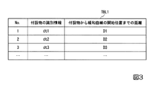
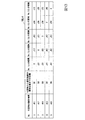
例えば、記憶部104は、図3に示す付設物の識別情報を示す画像情報と、その付設物が設けられている位置から緩和曲線の開始位置までの距離を示す距離情報との対応関係を第1データテーブルTBL1に記憶する。
The
For example, the
報知部105は、曲線開始位置特定部103が特定した緩和曲線の開始位置を報知する。報知部105は、例えば、表示部、スピーカ、振動部、発光部などである。
The
本発明の第二の実施形態による道路情報検出装置10の処理について説明する。
ここでは、高速道路を走行する車両が備える図4に示す道路情報検出装置10の処理フローについて説明する。
なお、付設物検出部102は、道路情報検出装置10の起動時に、記憶部104から第1データテーブルTBL1における付設物の識別情報を予め読み出しているとする。また、曲線開始位置特定部103は、道路情報検出装置10の起動時に、記憶部104から第1データテーブルTBL1を予め読み出しているとする。
Processing of the road
Here, a processing flow of the road
It is assumed that the
画像情報取得部101は、車両が高速道路を走行中に、車両の進行方向の画像を撮影する(ステップS1)。
画像情報取得部101は、撮影した画像の画像情報を付設物検出部102に送信する。
The image
The image
付設物検出部102は、画像情報取得部101から画像情報を受信する。
付設物検出部102は、画像情報を受信すると、受信した画像情報が示す画像において、予め読み出している付設物の識別情報を検出するか否かを判定する(ステップS2)。なお、予め読み出している付設物の識別情報は、付設物が道路標識である場合、例えば、速度制限80km/hを示す標識の中の“80”という文字である。また、予め読み出している付設物の識別情報は、付設物が距離標である場合、例えば、各高速道路の起点からの距離を示す距離標の中の“114.7”という文字である。また、予め読み出している付設物の識別情報は、付設物がETCガントリーである場合、例えば、各インターチェンジの名称である。
例えば、付設物検出部102は、マッチング技術を用いて、受信した画像情報が示す画像と、丸の中に“80”という文字が記載された付設物の識別情報を示す画像とを比較し、受信した画像情報が示す画像において丸の中に“80”という文字を検出するか否かを判定する。
また、付設物検出部102は、マッチング技術を用いて、受信した画像情報が示す画像と、“114.7”という文字が記載された付設物の識別情報を示す画像とを比較し、受信した画像情報が示す画像において“114.7”という文字を検出するか否かを判定する。
また、付設物検出部102は、画像処理におけるマッチング技術を用いて、受信した画像情報が示す画像と、ETCガントリーに示されるインターチェンジの名称の1つである“笠間西”という文字が記載された付設物の識別情報を示す画像とを比較し、受信した画像情報が示す画像において“笠間西”という文字を検出するか否かを判定する。
The
When receiving the image information, the
For example, the
Further, the
In addition, the attached
付設物検出部102は、受信した画像情報が示す画像において、記憶部104から予め読み出した付設物の識別情報に一致する識別情報を検出しないと判定した場合(ステップS2においてNO)、ステップS1の処理に戻す。
If the
付設物検出部102は、受信した画像情報が示す画像において、記憶部104から予め読み出した付設物の識別情報に一致する識別情報を検出したと判定した場合(ステップS2においてYES)、検出した付設物の識別情報と、付設物の識別情報を検出した画像とを曲線開始位置特定部103に送信する。
If the
曲線開始位置特定部103は、付設物検出部102から検出した付設物の識別情報と、付設物の識別情報を検出した画像とを受信する。
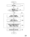
曲線開始位置特定部103は、付設物の識別情報と、付設物の識別情報を検出した画像とを受信すると、道路上の付設物の検出に基づいて道路の構造における緩和曲線の開始位置を特定する(ステップS3)。
例えば、曲線開始位置特定部103は、受信した付設物の識別情報に対応する付設物から緩和曲線の開始位置までの距離を第1データテーブルTBL1において特定する(ステップS3A)。
また、曲線開始位置特定部103は、付設物の識別情報を検出した画像に基づいて、車両から検出した付設物までの距離を算出する(ステップS3B)。
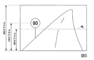
具体例として、曲線開始位置特定部103が速度制限80km/hを示す道路標識を検出した場合における車両から検出した付設物の識別情報までの距離の算出について説明する。
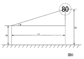
ここで、画像情報取得部101は、路面からの高さ1.2メートルの車両の位置に画角(視野角)の中心が路面に水平になるよう設置されているとする。また、付設物である道路標識は、設置基準が定められており標準的な設置の高さが定められている。ここでは、道路標識の識別情報の中心が、路面から高さ1.8メートルの位置に設置されているとする。また、画像情報取得部101の画角は、48度であるとする。
車両の曲線開始位置特定部103は、付設物検出部102から付設物の識別情報を検出した画像として、図5に示す画像を受信したとする。図5に示すように、付設物の識別情報を検出した画像において、画像の最下部から最上部までの縦方向の画素数は960ピクセルであるとする。また、付設物の識別情報を検出した画像において、画像の最下部から付設物の識別情報の中心までの縦方向の画素数は700ピクセルであるとする。また、付設物の識別情報を検出した画像において、画像の最下部から水平線HLまでの縦方向の画素数は650ピクセルであるとする。
また、車両に設置された画像情報取得部101と付設物との位置関係は、図6に示すような位置関係にあり、距離L1は、高さh1、高さh2、角度θを用いて、以下の式(1)のように表すことができる。
L1=(h2−h1)÷tanθ・・・(1)
ここで、距離L1は、車両に設置された画像情報取得部101から付設物までの距離である。高さh1は、画像情報取得部101が設置されている高さである。高さh2は、路面から付設物の識別情報の中心までの高さである。角度θは、画像情報取得部101の位置を基準点とし水平方向をゼロ度としたときに、画像情報取得部101と付設物の識別情報の中心を結んだ直線と、水平方向とが成す角度である。
高さh1は、1.2メートルであることが分かっている。高さh2は、1.8メートルであることが分かっている。したがって、距離L1は、角度θが分かれば求めることができる。
画像情報取得部101の画角は、48度であることが分かっている。また、付設物の識別情報を検出した画像において、画像の最下部から最上部までの縦方向の画素数は960ピクセルであることが分かっている。したがって、付設物の識別情報を検出した画像において、縦方向の1画素は、0.025(=(48÷2)÷960)度と算出することができる。
画像の最下部から付設物の識別情報の中心までの縦方向の画素数は530ピクセルであることが分かっている。また、付設物の識別情報を検出した画像において、画像の最下部から水平線HLまでの縦方向の画素数は480ピクセルであることが分かっている。画像の最下部から付設物の識別情報の中心までの縦方向の画素数と、付設物の識別情報を検出した画像において、画像の最下部から水平線HLまでの縦方向の画素数との差は、50(=530−480)ピクセルと算出することができる。
角度θは、付設物の識別情報を検出した画像において、画像の最下部から水平線HLまでの縦方向の画素数との差である50ピクセルに対応する角度であり、θ=1.25(=0.025×50)度と算出することができる。
したがって、曲線開始位置特定部103は、式(1)を用いて距離L1を、L1=27.5(=(1.8−1.2)÷tan1.25)メートルと算出する。
なお、曲線開始位置特定部103は、上述のアルゴリズムと異なるアルゴリズムで距離L1を算出してもよい。例えば、曲線開始位置特定部103は、“滝本周平、伊藤崇晶、「車載カメラを用いた単眼測距検証システムの開発」、SEIテクニカルレビュー、第169号、pp.82−87”などに記載されているピンホールカメラモデルを用いたアルゴリズムに基づいて距離L1を算出してもよい。また、曲線開始位置特定部103は、適切に距離L1を算出できれば、その他の距離計算アルゴリズムを用いてもよい。
また、曲線開始位置特定部103は、予め取得した付設物の位置情報と、GPS(Global Positioning System)により特定した車両の位置とに基づいて、距離L1を算出してもよい。具体的には、曲線開始位置特定部103は、付設物の位置とGPSにより特定した車両の位置との差が示す距離を算出する。
また、曲線開始位置特定部103は、付設物から発信されるビーコンに基づいて、距離L1を算出してもよい。具体的には、曲線開始位置特定部103は、予めビーコンの電波強度と距離との対応関係を取得しており、対応関係において受信したビーコンの電波強度が示す距離を特定する。
また、曲線開始位置特定部103は、予め取得した付設物の位置情報と、車輪の回転数から算出される車両の走行距離とに基づいて、距離L1を算出してもよい。具体的には、曲線開始位置特定部103は、例えば、インターチェンジを起点に車輪の回転数と車輪の周囲長とを乗算して走行距離を算出する。曲線開始位置特定部103は、付設物の位置とインターチェンジからの走行距離により示される位置との差が示す距離を算出する。
曲線開始位置特定部103は、第1データテーブルTBL1において特定した付設物から緩和曲線の開始位置までの距離と、算出した車両から検出した付設物までの距離とを加算する(ステップS3C)。
曲線開始位置特定部103は、算出した車両から付設物までの距離を報知部105に送信する。
The curve start
When the curve start
For example, the curve start
Further, the curve start
As a specific example, calculation of the distance from the vehicle to the attachment identification information detected when the curve start
Here, it is assumed that the image
It is assumed that the vehicle curve start
Further, the positional relationship between the image
L1 = (h2−h1) ÷ tan θ (1)
Here, the distance L1 is a distance from the image
The height h1 is known to be 1.2 meters. The height h2 has been found to be 1.8 meters. Therefore, the distance L1 can be obtained if the angle θ is known.
It is known that the angle of view of the image
It is known that the number of pixels in the vertical direction from the bottom of the image to the center of the identification information of the attachment is 530 pixels. In addition, it is known that the number of pixels in the vertical direction from the bottom of the image to the horizontal line HL is 480 pixels in the image in which the identification information of the attached object is detected. The difference between the number of pixels in the vertical direction from the bottom of the image to the center of the identification information of the attachment and the number of pixels in the vertical direction from the bottom of the image to the horizontal line HL in the image where the identification information of the attachment is detected is , 50 (= 530-480) pixels.
The angle θ is an angle corresponding to 50 pixels which is a difference from the number of pixels in the vertical direction from the bottom of the image to the horizontal line HL in the image where the identification information of the attached object is detected, and θ = 1.25 (= 0.025 × 50) degrees can be calculated.
Therefore, the curve start
The curve start
Further, the curve start
Further, the curve start
Further, the curve start
The curve start
The curve start
報知部105は、車両から付設物までの距離を曲線開始位置特定部103から受信する。
報知部105は、車両から付設物までの距離を受信すると、受信した距離に基づいて緩和曲線の開始位置を報知する(ステップS4)。
例えば、報知部105は、表示部であり、緩和曲線の開始位置が上り坂の開始位置である場合、図7に示すように、画像情報取得部101が取得する画像と共に、“300メートルで上り坂です”と文字を表示する。また、報知部105は、スピーカであり、緩和曲線の開始位置が上り坂の開始位置である場合、“300メートルで上り坂です”と音声を出力する。また、報知部105は、振動部である場合、車両から緩和曲線の開始位置までの距離に応じた振動の強さや間隔などで座席シートが振動する。また、報知部105は、発光部である場合、車両から緩和曲線の開始位置までの距離に応じた光の強さや点滅の間隔などで発光する。
The
When the notifying
For example, the
以上、本発明の第二の実施形態による道路情報検出装置10について説明した。
本発明の第二の実施形態による道路情報検出装置10は、画像情報取得部101と、付設物検出部102と、曲線開始位置特定部103と、記憶部104と、報知部105と、を備える。画像情報取得部101は、画像を取得する。付設物検出部102は、画像情報取得部101が取得した画像に映る付設物の識別情報を検出する。曲線開始位置特定部103は、道路上の付設物の検出に基づいて道路の構造における緩和曲線の開始位置を特定する。具体的には、曲線開始位置特定部103は、画像情報取得部101が取得した画像に映る付設物の識別情報と、第1データテーブルTBL1に記録されている付設物の位置と、その付設物から緩和曲線の開始位置までの距離とに基づいて、緩和曲線の開始位置を特定する。また、曲線開始位置特定部103は、付設物の識別情報を検出した画像に基づいて、車両から検出した付設物までの距離を算出する。曲線開始位置特定部103は、第1データテーブルTBL1において特定した付設物から緩和曲線の開始位置までの距離と、算出した車両から検出した付設物までの距離とを加算する。記憶部104は、道路情報検出装置10が行う処理に必要な種々の情報を記憶する。報知部105は、曲線開始位置特定部103が特定した緩和曲線の開始位置を報知する。
このようにすれば、道路情報検出装置10は、道路において、坂道やカーブの正確な開始位置を簡易的に特定することができる。
The road
The road
In this way, the road
<第三の実施形態>
本発明の第三の実施形態による道路情報検出装置について説明する。
本発明の第三の実施形態による道路情報検出装置10は、図2で示した第二の実施形態による道路情報検出装置10と同様に、画像情報取得部101と、付設物検出部102と、曲線開始位置特定部103と、記憶部104と、報知部105と、を備える。
<Third embodiment>
A road information detection apparatus according to a third embodiment of the present invention will be described.
The road
付設物検出部102は、画像情報取得部101が取得した画像に映る付設物の識別情報を所定回数検出するまで検出する。所定回数は、例えば、車両が現在走行中の道路と、他の道路とを区別できる回数である。また、所定回数は、例えば、車両が現在走行中の道路における現在の位置と、車両が現在走行中の道路における他の位置とを区別できる回数である。
The
曲線開始位置特定部103は、道路上の付設物の検出に基づいて道路の構造における緩和曲線の開始位置を特定する。
具体的には、曲線開始位置特定部103は、画像情報取得部101が取得した画像に映る付設物の順序を検出する。曲線開始位置特定部103は、付設物検出部102が最後に検出した付設物の識別情報と、後述する第2データテーブルTBL2に記録されている付設物の位置と、その付設物から緩和曲線の開始位置までの距離とに基づいて、緩和曲線の開始位置を特定する。
The curve start
Specifically, the curve start
記憶部104は、道路情報検出装置10が行う処理に必要な種々の情報を記憶する。
例えば、記憶部104は、図8に示すように、車両の走行中に出現する付設物の順序に並んだ付設物の識別情報を示す画像情報と、その付設物のうちの最後の付設物が設けられている位置から緩和曲線の開始位置までの距離を示す距離情報との対応関係を第2データテーブルTBL2に記憶する。
なお、第2データテーブルTBL2は、起点から終点に向かう下り方面、または、終点から起点に向かう上り方面に対して1つ作成し、上りと下りとで第2データテーブルTBL2のデータの読み取る順序を逆にすればよい。例えば、図8に示す上り方面用の第2データテーブルTBL2を使用する機能部は、上り方面に走行している車両に対しては、No.1からNo.100へデータを順に読み取り使用すればよい。また、図8に示す上り方面用の第2データテーブルTBL2を使用する機能部は、下り方面に走行している車両に対しては、No.100からNo.1へデータを順に読み取り使用すればよい。
The
For example, as shown in FIG. 8, the
Note that one second data table TBL2 is created for the downward direction from the start point to the end point, or the upward direction from the end point to the start point, and the order of reading the data in the second data table TBL2 is ascending and descending. Just reverse. For example, a functional unit that uses the second data table TBL2 for the upward direction shown in FIG. 1 to No. The data may be read and used in order to 100. Further, the function unit using the second data table TBL2 for the upward direction shown in FIG. 100 to No. The data may be read and used in order.
本発明の第二の実施形態による道路情報検出装置10は、特徴的な1つの付設物の識別情報を検出した場合、その付設物から緩和曲線の開始位置までの距離を用いて車両から緩和曲線の開始位置までの距離を算出することができる装置である。しかしながら、同一の付設物の識別情報が、他の道路、または、同一の道路における他の位置にも存在する場合もある。その場合、本発明の第二の実施形態による道路情報検出装置10は、検出した付設物の識別情報が、車両が現在走行している道路の付設物の識別情報であるか、他の道路の付設物の識別情報であるか、車両が現在走行している道路の他の位置における付設物の識別情報であるかを区別することができない。その結果、本発明の第二の実施形態による道路情報検出装置10は、同一の付設物の識別情報が、他の道路、または、同一の道路における他の位置にも存在する場合、車両から緩和曲線の開始位置までの距離を算出することができない。
本発明の第三の実施形態による道路情報検出装置10は、同一の付設物の識別情報が、他の道路、または、同一の道路における他の位置にも存在する場合に、車両から緩和曲線の開始位置までの距離を算出することができる装置である。
When the road
The road
本発明の第三の実施形態による道路情報検出装置10の処理について説明する。
ここでは、高速道路を走行する車両が備える図9に示す道路情報検出装置10の処理フローについて説明する。
なお、付設物検出部102は、道路情報検出装置10の起動時に、記憶部104から第2データテーブルTBL2における付設物の識別情報を予め読み出しているとする。また、曲線開始位置特定部103は、道路情報検出装置10の起動時に、記憶部104から第2データテーブルTBL2を予め読み出しているとする。
また、車両は、道路を上り方面に走行しているとする。
Processing of the road
Here, a processing flow of the road
It is assumed that the
Further, it is assumed that the vehicle is traveling on the road in the upward direction.
画像情報取得部101は、ステップS1の処理を行うと、撮影した画像の画像情報を付設物検出部102に送信する。
The image
付設物検出部102は、画像情報取得部101から画像情報を受信する。
付設物検出部102は、画像情報を受信すると、受信した画像情報が示す画像において、予め読み出している付設物の識別情報を検出するか否かを判定する(ステップS2)。
The
When receiving the image information, the
付設物検出部102は、受信した画像情報が示す画像において、予め読み出した付設物の識別情報に一致する識別情報を検出しないと判定した場合(ステップS2においてNO)、ステップS1の処理に戻す。
When it is determined that the identification information that matches the identification information of the accessory that has been read in advance is not detected in the image indicated by the received image information (NO in step S2), the
付設物検出部102は、受信した画像情報が示す画像において、予め読み出した付設物の識別情報に一致する識別情報を検出したと判定した場合(ステップS2においてYES)、検出したと判定した付設物の識別情報と同一の識別情報を第2データテーブルTBL2において特定する(ステップS5)。
付設物検出部102は、画像情報取得部101が取得した画像に映る付設物の識別情報を所定回数検出したか否かを判定する(ステップS6)。
When it is determined that the identification information matching the identification information of the accessory that has been read in advance is detected in the image indicated by the received image information (YES in step S2), the
The
付設物検出部102は、画像情報取得部101が取得した画像に映る付設物の識別情報を所定回数検出しないと判定した場合(ステップS6においてNO)、ステップS5の処理により第2データテーブルTBL2において特定した同一の識別情報と第2データテーブルTBL2における番号(No.)とを対応付けて記憶部104の第3データテーブルTBL3に記録する(ステップS7)。
付設物検出部102は、ステップS5の処理により第2データテーブルTBL2において特定した同一の識別情報と第2データテーブルTBL2における番号とを対応付けて記憶部104に記録したことを報知する記録報知信号を画像情報取得部101に送信する。
When the
The
画像情報取得部101は、付設物検出部102から記録報知信号を受信する。
画像情報取得部101は、記録報知信号を受信すると、車両が高速道路を走行中に、車両の進行方向の画像を撮影する(ステップS8)。
画像情報取得部101は、撮影した画像の画像情報を付設物検出部102に送信する。
The image
When receiving the recording notification signal, the image
The image
付設物検出部102は、画像情報取得部101から画像情報を受信する。
付設物検出部102は、画像情報を受信すると、受信した画像情報が示す画像において、予め読み出している付設物の識別情報を検出するか否かを判定する(ステップS9)。
The
When receiving the image information, the
付設物検出部102は、受信した画像情報が示す画像において、記憶部104から予め読み出した付設物の識別情報に一致する識別情報を検出しないと判定した場合(ステップS9においてNO)、ステップS8の処理に戻す。
If the
付設物検出部102は、受信した画像情報が示す画像において、記憶部104から予め読み出した付設物の識別情報に一致する識別情報を検出したと判定した場合(ステップS9においてYES)、記憶部104から第3データテーブルTBL3を読み出す。
付設物検出部102は、第3データテーブルTBL3を読み出すと、第3データテーブルTBL3に記録された番号のそれぞれの次の番号に対応する第2データテーブルTBL2における付設物の識別情報において、ステップS9の処理により検出したと判定した付設物の識別情報と同一の識別情報と一致する識別情報を特定する(ステップS10)。付設物検出部102は、ステップS6の処理に戻す。
When the
When the attached
また、付設物検出部102は、画像情報取得部101が取得した画像に映る付設物の識別情報を所定回数検出したと判定した場合(ステップS6においてYES)、最後に検出した付設物の識別情報と付設物の識別情報を検出した画像とを曲線開始位置特定部103に送信する。
Further, when the
曲線開始位置特定部103は、付設物検出部102が最後に検出した付設物の識別情報と付設物の識別情報を検出した画像とを付設物検出部102から受信する。
曲線開始位置特定部103は、付設物検出部102が最後に検出した付設物の識別情報と付設物の識別情報を検出した画像とを受信すると、ステップS3の処理により、付設物検出部102が最後に検出した付設物の識別情報と、付設物検出部102が最後に検出した付設物の識別情報を検出した画像とを受信すると、道路上の付設物の検出に基づいて道路の構造における緩和曲線の開始位置を特定する。
道路情報検出装置10は、ステップS4の処理を行う。
The curve start
When the curve start
The road
図9に示す処理フローにおけるステップS2においてYES、S5、S6においてNO、S7〜S10の処理の具体例として、第2データテーブルTBL2が図8で示したデータテーブルである場合の識別情報の特定について説明する。
付設物検出部102は、ステップS2の処理により、受信した画像情報が示す画像において、記憶部104から予め読み出した付設物の識別情報dt1に一致する識別情報を検出したと判定したとする(ステップS2においてYES)。この場合、付設物検出部102は、ステップS5の処理により、第2データテーブルTBL2におけるNo.31の付設物の識別情報dt1と、No.61の付設物の識別情報dt1とを特定する。
付設物検出部102は、ステップS6の処理により、第2データテーブルTBL2において付設物の識別情報dt1がNo.1、No.31、No.61のそれぞれに存在し、1つに特定できないため、画像情報取得部101が取得した画像に映る付設物の識別情報を所定回数検出しないと判定する(ステップS6においてNO)。
付設物検出部102は、ステップS7の処理により、付設物の識別情報dt1とNo.1とを対応付けて記憶部104の第3データテーブルTBL3に記録する。また、付設物検出部102は、ステップS7の処理により、付設物の識別情報dt1とNo.31とを対応付けて記憶部104の第3データテーブルTBL3に記録する。また、付設物検出部102は、ステップS7の処理により、付設物の識別情報dt1とNo.61とを対応付けて記憶部104の第3データテーブルTBL3に記録する。
付設物検出部102は、付設物の識別情報dt1とNo.1、付設物の識別情報dt1とNo.31、付設物の識別情報dt1とNo.61を対応付けて記憶部104の第3データテーブルTBL3に記録したことを報知する記録報知信号を画像情報取得部101に送信する。
In step S2 in the process flow shown in FIG. 9, NO in steps S5 and S6, and identification of identification information when the second data table TBL2 is the data table shown in FIG. explain.
The
By the process of step S6, the
The
The
画像情報取得部101は、付設物検出部102から記録報知信号を受信する。
画像情報取得部101は、ステップS8の処理により、記録報知信号を受信すると、車両が高速道路を走行中に、車両の進行方向の画像を撮影する。
画像情報取得部101は、撮影した画像の画像情報を付設物検出部102に送信する。
The image
When the image
The image
付設物検出部102は、画像情報取得部101から画像情報を受信する。
付設物検出部102は、画像情報を受信すると、ステップS9の処理により、受信した画像情報が示す画像において、予め読み出している付設物の識別情報を検出するか否かを判定する。
The
When receiving the image information, the
付設物検出部102は、ステップS9の処理により、受信した画像情報が示す画像において、記憶部104から予め読み出した付設物の識別情報に一致する識別情報を検出しないと判定した場合(ステップS9においてNO)、ステップS8の処理に戻す。
If the
付設物検出部102は、ステップS9の処理により、受信した画像情報が示す画像において、記憶部104から予め読み出した付設物の識別情報に一致する付設物の識別情報dt2を検出したと判定した場合(ステップS9においてYES)、記憶部104から第3データテーブルTBL3を読み出す。
付設物検出部102は、第3データテーブルTBL3を読み出すと、ステップS9の処理により、第3データテーブルTBL3に記録されたNo.1、No.31、No.61のそれぞれの次の番号No.2、No.32、No.62に対応する第2データテーブルTBL2における付設物の識別情報において、付設物の識別情報dt2と一致する識別情報をNo.2に対応する付設物の識別情報dt2と特定する。付設物検出部102は、ステップS6の処理に戻す。
When the
When the
また、付設物検出部102は、ステップS6の処理により、付設物の識別情報dt2と一致する識別情報がNo.2に対応する付設物の識別情報dt2の1つとなり、画像情報取得部101が取得した画像に映る付設物の識別情報を所定回数検出したと判定する(ステップS6においてYES)。付設物検出部102は、最後に検出したNo.2に対応する付設物の識別情報dt2と、付設物の識別情報を検出した画像とを曲線開始位置特定部103に送信する。
Further, the
以上、本発明の第三の実施形態による道路情報検出装置10について説明した。
本発明の第三の実施形態による道路情報検出装置10は、画像情報取得部101と、付設物検出部102と、曲線開始位置特定部103と、記憶部104と、報知部105と、を備える。画像情報取得部101は、画像を取得する。付設物検出部102は、画像情報取得部101が取得した画像に映る付設物の識別情報を所定回数検出するまで検出する。曲線開始位置特定部103は、道路上の付設物の検出に基づいて道路の構造における緩和曲線の開始位置を特定する。具体的には、曲線開始位置特定部103は、画像情報取得部101が取得した画像に映る付設物の順序を検出する。曲線開始位置特定部103は、付設物検出部102が最後に検出した付設物の識別情報と、第2データテーブルTBL2に記録されている付設物の位置と、その付設物から緩和曲線の開始位置までの距離とに基づいて、緩和曲線の開始位置を特定する記憶部104は、道路情報検出装置10が行う処理に必要な種々の情報を記憶する。報知部105は、曲線開始位置特定部103が特定した緩和曲線の開始位置を報知する。
このようにすれば、道路情報検出装置10は、道路において、坂道やカーブの正確な開始位置を簡易的に特定することができる。
The road
The road
In this way, the road
<第四の実施形態>
本発明の第四の実施形態による道路情報検出システムについて説明する。
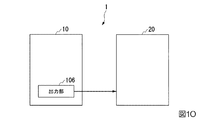
本発明の第四の実施形態による道路情報検出システム1は、図10に示すように、出力部106を更に備える道路情報検出装置10と、運転支援装置20と、を備える。
<Fourth embodiment>
A road information detection system according to a fourth embodiment of the present invention will be described.
As shown in FIG. 10, the road
出力部106を更に備える道路情報検出装置10は、例えば、本発明の第一から第三の何れかの実施形態による道路情報検出装置10が更に出力部106を備える道路情報検出装置である。
出力部106は、曲線開始位置特定部103が特定した緩和曲線の開始位置を運転支援装置20に出力する。
The road
The
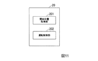
運転支援装置20は、図11に示すように、開始位置取得部201と、運転制御部202と、を備える。
開始位置取得部201は、道路情報検出装置10から緩和曲線の開始位置を取得する。
運転制御部202は、開始位置取得部201が取得した緩和曲線の開始位置に基づいて車両の加速制御を行う。
また、運転制御部202は、開始位置取得部201が取得した緩和曲線の開始位置に基づいて車両の制動制御を行う。
また、運転制御部202は、開始位置取得部201が取得した緩和曲線の開始位置に基づいて車両の進行方向変更制御を行う。
As illustrated in FIG. 11, the driving
The start
The
In addition, the
In addition, the
本発明の第四の実施形態による道路情報検出システム1の処理について説明する。
ここでは、高速道路を走行する車両が備える図12に示す道路情報検出装置10の処理フローについて説明する。
図12に示す処理フローにおけるステップS1〜S10は、図9で示した処理フローを示している。
Processing of the road
Here, a processing flow of the road
Steps S1 to S10 in the processing flow shown in FIG. 12 show the processing flow shown in FIG.
曲線開始位置特定部103は、算出した車両から付設物までの距離を報知部105と、出力部106とに送信する。
The curve start
報知部105は、車両から付設物までの距離を曲線開始位置特定部103から受信する。
報知部105は、ステップS4の処理により、車両から付設物までの距離を受信すると、受信した距離に基づいて緩和曲線の開始位置を報知する。
The
When the
出力部106は、車両から付設物までの距離を曲線開始位置特定部103から受信する。
出力部106は、車両から付設物までの距離を受信すると、受信した距離に基づいて緩和曲線の開始位置を運転支援装置20に送信する。
The
When receiving the distance from the vehicle to the accessory, the
開始位置取得部201は、道路情報検出装置10から緩和曲線の開始位置を受信する(ステップS12)。
開始位置取得部201は、緩和曲線の開始位置を受信すると、受信した緩和曲線の開始位置を運転制御部202に送信する。
The start
When the start
運転制御部202は、開始位置取得部201から緩和曲線の開始位置を受信する。
運転制御部202は、緩和曲線の開始位置を受信すると、受信した緩和曲線の開始位置に基づいて、車両の走行を自動制御する(ステップS13)。
具体的には、運転制御部202は、受信した緩和曲線の開始位置が上り坂の開始位置である場合、車両の加速制御を行う。
また、運転制御部202は、受信した緩和曲線の開始位置が下り坂の開始位置である場合、車両の制動制御を行う。なお、車両がモータを有している場合、回生ブレーキを利用して発電してもよい。
また、運転制御部202は、受信した緩和曲線の開始位置がカーブの開始位置である場合、車両の進行方向変更制御を行う。
The
When receiving the start position of the relaxation curve, the
Specifically, the driving
In addition, the
Further, when the start position of the received relaxation curve is the start position of the curve, the
以上、本発明の第四の実施形態による道路情報検出システム1について説明した。
本発明の第四の実施形態による道路情報検出システム1は、出力部106を更に備える道路情報検出装置10と、運転支援装置20と、を備える。出力部106は、曲線開始位置特定部103が特定した緩和曲線の開始位置を運転支援装置20に出力する。運転支援装置20は、開始位置取得部201と、運転制御部202と、を備える。開始位置取得部201は、道路情報検出装置10から緩和曲線の開始位置を取得する。運転制御部202は、開始位置取得部201が取得した緩和曲線の開始位置に基づいて車両の加速制御を行う。また、運転制御部202は、開始位置取得部201が取得した緩和曲線の開始位置に基づいて車両の制動制御を行う。また、運転制御部202は、開始位置取得部201が取得した緩和曲線の開始位置に基づいて車両の進行方向変更制御を行う。
このようにすれば、道路情報検出システム1において、道路情報検出装置10は、道路において、坂道やカーブの正確な開始位置を簡易的に特定することができる。また、運転支援装置20は、道路情報検出装置10が特定した坂道やカーブの正確な開始位置に基づいて、運転を支援することができる。
The road
The road
In this way, in the road
なお、道路情報検出システム1において、道路情報検出装置10が道路の設計時の想定速度の情報を取得し、運転支援装置20は、その想定速度になるように車両の速度を制御してもよい。また、運転支援装置20が行う車両の速度の制御は、自動制御であってもよい。
このようにすれば、道路情報検出システム1は、車両を安全に走行させることができる。
In the road
In this way, the road
なお、図12に示す処理フローにおけるステップS1〜S10の処理の代わりに、図4で示した処理フローのステップS1〜S4の処理を行ってもよい。 In addition, you may perform the process of step S1-S4 of the process flow shown in FIG. 4 instead of the process of step S1-S10 in the process flow shown in FIG.
なお、本発明の各実施形態において、曲線開始位置特定部103は、白線の数を数えることにより白線の数を数え始める位置からの距離を推定してもよい。
例えば、高速道路における白線の標準的な長さは8メートルであり、白線の標準的な間隔は12メートルであることが分かっている。
曲線開始位置特定部103は、画像情報取得部101が取得した画像に対して、画像処理における画像認識の技術を用いて、白線の出現回数を数える。曲線開始位置特定部103は、20メートル(=白線の長さ8メートル+白線の間隔12メートル)に出現回数を乗算することにより、20メートル刻みで白線の数を数え始める位置からの距離を推定することができる。
このようにすれば、道路情報検出装置10は、道路において、坂道やカーブの開始位置を簡易的でより正確に特定することができる。
In each embodiment of the present invention, the curve start
For example, it has been found that the standard length of white lines on a highway is 8 meters and the standard spacing of white lines is 12 meters.
The curve start
In this way, the road
また、本発明の各実施形態において、道路上の付設物は、非常電話であってもよい。非常電話は、明かり部が約1キロメートル間隔であり、トンネル内に200メートル間隔(首都高速道路では明かり部が500メートル間隔であり、トンネル内に100メートル間隔)で設置されていることが分かっている。
曲線開始位置特定部103は、画像情報取得部101が取得した画像に対して、画像処理における画像認識の技術を用いて、明かり部の出現回数やトンネル内の非常電話の出現回数を数える。曲線開始位置特定部103は、明かり部の出現回数やトンネル内の非常電話の出現回数に明かり部またはトンネル内の非常電話の間隔が示す距離を乗算することで、白線の場合と同様に、明かり部またはトンネル内の非常電話の出現回数を数え始める位置からの距離を推定することができる。
このようにすれば、道路情報検出装置10は、道路において、坂道やカーブの開始位置を簡易的でより正確に特定することができる。
In each embodiment of the present invention, the accessory on the road may be an emergency telephone. It is understood that emergency telephones are installed at intervals of about 1 kilometer in the light section and at intervals of 200 meters in the tunnel (light sections on the Metropolitan Expressway are at intervals of 500 meters and at intervals of 100 meters in the tunnel). Yes.
The curve start
In this way, the road
また、本発明の各実施形態において、曲線開始位置特定部103は、距離標(大型の距離標は500メートル間隔で設置、小型の距離標は100メートル間隔で設置)の出現回数を数えることにより、上述の白線や非常電話の場合と同様に、距離標の出現回数を数え始める位置からの距離を推定することができる。
このようにすれば、道路情報検出装置10は、道路において、坂道やカーブの開始位置を簡易的でより正確に特定することができる。
In each embodiment of the present invention, the curve start
In this way, the road
また、本発明の各実施形態において、付設物検出部102は、道路上の付設物として、高速道路の分合流地点におけるデルタ形状の白線を検出する。曲線開始位置特定部103は、走行中のデルタ形状の白線の出現の順番と、記憶部104が予め記録しているデルタ形状の白線の出現の順番を照合することにより、車両の現在位置を推定することができる。
このようにすれば、道路情報検出装置10は、道路において、坂道やカーブの開始位置を簡易的でより正確に特定することができる。
Moreover, in each embodiment of this invention, the
In this way, the road
また、本発明の各実施形態において、付設物検出部102は、道路上の付設物として、路面に記載された行先、逆走防止の矢印を検出する。曲線開始位置特定部103は、走行中の路面に記載された行先、逆走防止の矢印の出現の順番と、記憶部104が予め記録している路面に記載された行先、逆走防止の矢印の出現順序と照合することにより、車両の現在位置(走行している区間)を推定することができる。
このようにすれば、道路情報検出装置10は、道路において、坂道やカーブの開始位置を簡易的でより正確に特定することができる。
Moreover, in each embodiment of this invention, the
In this way, the road
なお、本発明の各実施形態において、道路情報検出装置10は、上述の坂道やカーブの開始位置をより正確に特定する方法を併用してもよい。
このようにすれば、道路情報検出装置10は、道路において、坂道やカーブの開始位置を簡易的でより正確に特定することができる。
In each embodiment of the present invention, the road
In this way, the road
なお、本発明の各実施形態において、曲線開始位置特定部103は、道路上に本来存在する付設物が存在しない場合、以下のように付設物を推定すれば、緩和曲線の開始位置を推定することができる。
具体例として、No.1から5までの5つの付設物が道路上に本来存在するはずが、No.4の付設物が故障し、4つの付設物しか存在しない場合の緩和曲線の開始位置の推定について説明する。なお、車両は、No.1から5へ向かう方向へ走行しているとする。
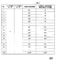
図13に示す第4データテーブルTBL4のように、No.1から5までの5つの付設物のそれぞれの間隔(距離)を予め取得し記録する。
付設物検出部102は、車両の走行中、No.1、No.2、No.3、No.5の付設物の順に検出する。
曲線開始位置特定部103は、車両が走行中に付設物検出部102が付設物を検出する度に、前回検出した付設物と今回検出した付設物との間隔を取得する。
例えば、曲線開始位置特定部103は、車両の走行距離に基づいて前回検出した付設物と今回検出した付設物との間隔を算出する。また、例えば、曲線開始位置特定部103は、道路上の付設物、または、道路上の付設物の近辺に設けられた装置から放送、ビーコンなどの通信を用いて本来存在するNo.4が存在する場合の間隔を取得してもよい。
曲線開始位置特定部103は、車両の走行距離に基づいて前回検出した付設物と今回検出した付設物との間隔を算出した場合、本来間隔J14を取得するはずが間隔J15を取得することになる。曲線開始位置特定部103は、同様に、間隔J24の代わりに間隔J25、間隔J34の代わりに間隔J35、間隔J41の代わりに間隔J51、間隔J42の代わりに間隔J52、間隔J43の代わりに間隔J53、間隔J54の代わりにゼロ、間隔J45の代わりにゼロを取得することになる。しかしながら、曲線開始位置特定部103は、予め第4データテーブルTBL4の間隔の情報を取得していれば、車両の走行中に取得した間隔が、第4データテーブルTBL4に存在する。また、曲線開始位置特定部103は、車両の走行中に取得した間隔が、第4データテーブルTBL4以外のデータテーブルでは出現する可能性が低いことが想定できる。そのため、曲線開始位置特定部103は、付設物検出部102が4番目に検出した付設物は、No.4の付設物ではなくNo.5の付設物であると推定することができる。
また、道路上の付設物の近辺に設けられた装置から放送、ビーコンなどの通信を用いて本来存在するNo.4が存在する場合の間隔を取得した場合にも、曲線開始位置特定部103は、第4データテーブルTBL4に存在する間隔を取得する。そのため、曲線開始位置特定部103は、付設物検出部102が4番目に検出した付設物は、No.4の付設物ではなくNo.5の付設物であると推定することができる。
以上のように、曲線開始位置特定部103は、いくつかの付設物が存在しない場合であっても、第4データテーブルTBL4のように、付設物どうしの間隔の情報を用いることで、付設物検出部102が検出した付設物を推定することができる。
In each embodiment of the present invention, the curve start
As a specific example, no. Five attachments from 1 to 5 should originally exist on the road. The estimation of the start position of the relaxation curve in the case where 4 attachments fail and only 4 attachments exist will be described. The vehicle is No. Suppose you are traveling in the direction from 1 to 5.
As in the fourth data table TBL4 shown in FIG. The interval (distance) of each of the five attachments from 1 to 5 is acquired and recorded in advance.
The
The curve start
For example, the curve start
When calculating the interval between the attachment detected last time and the attachment detected this time based on the travel distance of the vehicle, the curve start
In addition, No. which originally exists by using communication such as broadcast and beacon from a device provided in the vicinity of an accessory on the road. Also when the interval when 4 exists is acquired, the curve start
As described above, the curve start
なお、本発明の各実施形態において、曲線開始位置特定部103は、付設物から緩和曲線の開始位置までの距離の情報を、道路上の付設物、または、道路上の付設物の近辺に設けられた装置から放送、ビーコンなどの通信を用いて取得してもよい。
In each embodiment of the present invention, the curve start
また、10キロポストと11キロポストの間が3車線であり、車線数を記憶部104に記憶する場合、“10 11 3”と記憶部104に記録することによりメモリ容量を低減してもよい。
Further, when there are three lanes between the 10 km post and the 11 km post and the number of lanes is stored in the
なお、本発明の実施形態における処理フローは、適切な処理が行われる範囲において、処理の順番が入れ替わってもよい。 In the processing flow in the embodiment of the present invention, the order of processing may be changed within a range where appropriate processing is performed.
本発明の実施形態における記憶部104、その他の記憶部のそれぞれは、適切な情報の送受信が行われる範囲においてどこに備えられていてもよい。また、記憶部104、その他の記憶部のそれぞれは、適切な情報の送受信が行われる範囲において複数存在しデータを分散して記憶していてもよい。
Each of the
本発明の実施形態について説明したが、上述の道路情報検出装置10、運転支援装置20のそれぞれは内部に、コンピュータシステムを有していてもよい。そして、上述した処理の過程は、プログラムの形式でコンピュータ読み取り可能な記録媒体に記憶されており、このプログラムをコンピュータが読み出して実行することによって、上記処理が行われる。ここでコンピュータ読み取り可能な記録媒体とは、磁気ディスク、光磁気ディスク、CD−ROM、DVD−ROM、半導体メモリ等をいう。また、このコンピュータプログラムを通信回線によってコンピュータに配信し、この配信を受けたコンピュータがそのプログラムを実行するようにしてもよい。
Although the embodiment of the present invention has been described, each of the road
また、上記プログラムは、前述した機能の一部を実現してもよい。さらに、上記プログラムは、前述した機能をコンピュータシステムにすでに記録されているプログラムとの組み合わせで実現できるファイル、いわゆる差分ファイル(差分プログラム)であってもよい。 The program may realize part of the functions described above. Further, the program may be a so-called difference file (difference program) that can realize the above-described functions in combination with a program already recorded in the computer system.
本発明のいくつかの実施形態を説明したが、これらの実施形態は、例であり、発明の範囲を限定しない。これらの実施形態は、発明の要旨を逸脱しない範囲で、追加、種々の省略、置き換え、変更を行ってよい。 Although several embodiments of the present invention have been described, these embodiments are examples and do not limit the scope of the invention. These embodiments may be added, variously omitted, replaced, and changed without departing from the gist of the invention.
10・・・道路情報検出装置
20・・・運転支援装置
101・・・画像情報取得部
102・・・付設物検出部
103・・・曲線開始位置特定部
104・・・記憶部
105・・・報知部
106・・・出力部
201・・・開始位置取得部
202・・・運転制御部
DESCRIPTION OF
Claims (15)
を備える道路情報検出装置。 A curve start position specifying unit for specifying a start position of a relaxation curve in the structure of the road based on detection of an accessory on the road;
A road information detection device comprising:
前記画像に映る前記付設物の識別情報を検出する付設物検出部と、
を備え、
前記曲線開始位置特定部は、
前記画像に映る前記付設物の識別情報と、記憶部に記録されている付設物の位置と、当該付設物から前記緩和曲線の開始位置までの距離とに基づいて、前記開始位置を特定する、
請求項1に記載の道路情報検出装置。 An image information acquisition unit for acquiring images;
An attachment detection unit for detecting identification information of the attachment shown in the image;
With
The curve start position specifying unit is
The start position is identified based on the identification information of the attachment shown in the image, the position of the attachment recorded in the storage unit, and the distance from the attachment to the start position of the relaxation curve.
The road information detection device according to claim 1.
前記付設物検出部が前記付設物の出現した順序に当該付設物を検出し、最後に検出した付設物の識別情報と、記憶部に記録されている付設物の位置と、当該付設物から前記緩和曲線の開始位置までの距離とに基づいて、前記開始位置を特定する、
請求項2に記載の道路情報検出装置。 The curve start position specifying unit is
The attachment detection unit detects the attachment in the order in which the attachments appear, and the identification information of the attachment detected last, the position of the attachment recorded in the storage unit, and the attachment from the attachment Identifying the start position based on the distance to the start position of the relaxation curve;
The road information detection device according to claim 2.
請求項1から請求項3の何れか一項に記載の道路情報検出装置。 The curve start position specifying unit calculates a distance from the vehicle to the detected accessory based on an image in which the identification information of the accessory is detected.
The road information detection device according to any one of claims 1 to 3.
請求項1から請求項3の何れか一項に記載の道路情報検出装置。 The curve start position specifying unit calculates the distance from the vehicle to the accessory based on the position information of the accessory acquired in advance and the position of the vehicle specified by GPS (Global Positioning System).
The road information detection device according to any one of claims 1 to 3.
請求項1から請求項3の何れか一項に記載の道路情報検出装置。 The curve start position specifying unit calculates a distance from a vehicle to the attachment based on a beacon transmitted from the attachment.
The road information detection device according to any one of claims 1 to 3.
請求項1から請求項3の何れか一項に記載の道路情報検出装置。 The curve start position specifying unit calculates the distance from the vehicle to the accessory based on the position information of the accessory acquired in advance and the travel distance of the vehicle calculated from the rotation speed of the wheel.
The road information detection device according to any one of claims 1 to 3.
を備える請求項1から請求項7の何れか一項に記載の道路情報検出装置。 An output unit for outputting the start position to the driving support device;
The road information detection device according to any one of claims 1 to 7, further comprising:
前記開始位置に基づいて加速制御または制動制御または進行方向変更制御を行う運転制御部と、
を備える運転支援装置。 A start position acquisition unit that acquires the start position from a road information detection device that includes a curve start position specifying unit that specifies a start position of a relaxation curve in the structure of the road based on detection of an accessory on the road;
An operation control unit that performs acceleration control, braking control, or traveling direction change control based on the start position;
A driving support apparatus comprising:
検出した道路上の付設物の位置情報と前記道路情報とに基づいて前記道路の構造における緩和曲線の開始位置を特定する曲線開始位置特定部を備える道路情報検出装置と、
を備える道路情報検出システム。 Road information distribution system that distributes road information including at least identification information about an attachment on a road, position information about the attachment, and information indicating a relationship between the position information and a start position of a relaxation curve in the structure of the road;
A road information detection device comprising a curve start position specifying unit for specifying a start position of a relaxation curve in the structure of the road based on the detected position information of the accessory on the road and the road information;
A road information detection system comprising:
を含む道路情報検出装置の道路情報検出方法。 Identifying the starting position of the relaxation curve in the structure of the road based on the detection of attachments on the road;
A road information detection method for a road information detection apparatus including:
前記開始位置に基づいて加速制御または制動制御または進行方向変更制御を行うこと、
を含む運転支援装置の運転制御方法。 Obtaining the start position from a road information detection device comprising a curve start position specifying unit that specifies a start position of a relaxation curve in the structure of the road based on detection of an accessory on the road;
Performing acceleration control or braking control or traveling direction change control based on the start position;
The driving control method of the driving assistance device including
検出した道路上の付設物の位置情報と前記道路情報とに基づいて前記道路の構造における緩和曲線の開始位置を特定すること、
を含む道路情報検出システムの道路情報検出方法。 Distributing road information including at least identification information relating to attachments on the road, position information relating to the attachments, and information indicating a relationship between the position information and a start position of a relaxation curve in the structure of the road;
Identifying the start position of the relaxation curve in the structure of the road based on the position information of the accessory on the detected road and the road information;
Road information detection method for road information detection system including
道路上の付設物の検出に基づいて前記道路の構造における緩和曲線の開始位置を特定すること、
を実行させるプログラム。 On the computer,
Identifying the starting position of the relaxation curve in the structure of the road based on the detection of attachments on the road;
A program that executes
道路上の付設物の検出に基づいて前記道路の構造における緩和曲線の開始位置を特定する曲線開始位置特定部を備える道路情報検出装置から前記開始位置を取得すること、
前記開始位置に基づいて加速制御または制動制御または進行方向変更制御を行うこと、
を実行させるプログラム。 On the computer,
Obtaining the start position from a road information detection device comprising a curve start position specifying unit that specifies a start position of a relaxation curve in the structure of the road based on detection of an accessory on the road;
Performing acceleration control or braking control or traveling direction change control based on the start position;
A program that executes
Priority Applications (7)
| Application Number | Priority Date | Filing Date | Title |
|---|---|---|---|
| JP2015246388A JP6638373B2 (en) | 2015-12-17 | 2015-12-17 | Road information detection device, road information detection system, road information detection method and program |
| CA3008416A CA3008416C (en) | 2015-12-17 | 2016-12-12 | Road information detection device, driving assistance device, road information detection system, road information detection method, driving control method and program |
| HK18115605.5A HK1256536A1 (en) | 2015-12-17 | 2016-12-12 | Road information detection device, driving assistance device, road information detection system, road information detection method, driving control method and program |
| EP16875588.2A EP3392857A4 (en) | 2015-12-17 | 2016-12-12 | ROAD INFORMATION DETECTING DEVICE, DRIVING ASSISTANCE DEVICE, ROAD INFORMATION DETECTING SYSTEM, ROAD INFORMATION DETECTING METHOD, CONTROL DRIVER CONTROL METHOD, AND PROGRAM |
| PCT/JP2016/086906 WO2017104611A1 (en) | 2015-12-17 | 2016-12-12 | Road information detection device, driving assistance device, road information detection system, road information detection method, driving control method and program |
| MX2018007244A MX390907B (en) | 2015-12-17 | 2016-12-12 | ROAD INFORMATION DETECTION DEVICE, DRIVING ASSISTANCE DEVICE, ROAD INFORMATION DETECTION SYSTEM, ROAD INFORMATION DETECTION METHOD, DRIVING CONTROL METHOD AND PROGRAM. |
| US16/061,726 US11260871B2 (en) | 2015-12-17 | 2016-12-12 | Road information detection device, driving assistance device, road information detection system, road information detection method, driving control method and program |
Applications Claiming Priority (1)
| Application Number | Priority Date | Filing Date | Title |
|---|---|---|---|
| JP2015246388A JP6638373B2 (en) | 2015-12-17 | 2015-12-17 | Road information detection device, road information detection system, road information detection method and program |
Publications (3)
| Publication Number | Publication Date |
|---|---|
| JP2017111663A true JP2017111663A (en) | 2017-06-22 |
| JP2017111663A5 JP2017111663A5 (en) | 2018-08-16 |
| JP6638373B2 JP6638373B2 (en) | 2020-01-29 |
Family
ID=59056639
Family Applications (1)
| Application Number | Title | Priority Date | Filing Date |
|---|---|---|---|
| JP2015246388A Active JP6638373B2 (en) | 2015-12-17 | 2015-12-17 | Road information detection device, road information detection system, road information detection method and program |
Country Status (7)
| Country | Link |
|---|---|
| US (1) | US11260871B2 (en) |
| EP (1) | EP3392857A4 (en) |
| JP (1) | JP6638373B2 (en) |
| CA (1) | CA3008416C (en) |
| HK (1) | HK1256536A1 (en) |
| MX (1) | MX390907B (en) |
| WO (1) | WO2017104611A1 (en) |
Families Citing this family (3)
| Publication number | Priority date | Publication date | Assignee | Title |
|---|---|---|---|---|
| JP6638373B2 (en) * | 2015-12-17 | 2020-01-29 | 日本電気株式会社 | Road information detection device, road information detection system, road information detection method and program |
| CN114694105B (en) * | 2022-02-16 | 2025-10-03 | 阿里云计算有限公司 | Method, device, storage medium and processor for processing road gantry position information |
| CN115393813B (en) * | 2022-08-18 | 2023-05-02 | 中国人民公安大学 | Road identification method, device, equipment and storage medium based on remote sensing image |
Citations (10)
| Publication number | Priority date | Publication date | Assignee | Title |
|---|---|---|---|---|
| JP2005189004A (en) * | 2003-12-24 | 2005-07-14 | Aisin Aw Co Ltd | Navigation device |
| JP2007047129A (en) * | 2005-08-12 | 2007-02-22 | Osaka Prefecture Univ | POSITIONING DEVICE, NAVIGATION DEVICE, AND NAVIGATION SYSTEM |
| JP2008286566A (en) * | 2007-05-16 | 2008-11-27 | Omron Corp | In-vehicle device |
| JP2009014645A (en) * | 2007-07-09 | 2009-01-22 | Honda Motor Co Ltd | Vehicle distance measuring device |
| JP2009040329A (en) * | 2007-08-10 | 2009-02-26 | Aisin Aw Co Ltd | Traveling support device, traveling support method, and traveling support program |
| JP2010117839A (en) * | 2008-11-12 | 2010-05-27 | Aisin Aw Co Ltd | Vehicle drive supporting apparatus and vehicle drive supporting program |
| JP2010282278A (en) * | 2009-06-02 | 2010-12-16 | Mitsubishi Electric Corp | Sign recognition device |
| JP2011017989A (en) * | 2009-07-10 | 2011-01-27 | Aisin Aw Co Ltd | Device, method and program for evaluating reliability |
| JP2012164254A (en) * | 2011-02-09 | 2012-08-30 | Denso Corp | Sign recognition device |
| JP2014069799A (en) * | 2012-09-28 | 2014-04-21 | Hitachi Ltd | Method and system for giving driving support |
Family Cites Families (24)
| Publication number | Priority date | Publication date | Assignee | Title |
|---|---|---|---|---|
| JPH0771973A (en) | 1993-09-06 | 1995-03-17 | Sumitomo Electric Ind Ltd | Position detector |
| JP3578512B2 (en) * | 1995-04-21 | 2004-10-20 | 株式会社ザナヴィ・インフォマティクス | Current position calculating device and distance coefficient correcting method thereof |
| DE69731125T2 (en) * | 1997-06-17 | 2005-02-17 | Motorola Ltd., Basingstoke | Cordless device, control method and system for protected locations with interference parameters corresponding to operation |
| US6014595A (en) * | 1997-12-23 | 2000-01-11 | Honda Giken Kogyo Kabushiki Kaisha | Determination of vehicle assistance from vehicle vibration that results when the vehicle contacts vibration generating structures on the road |
| JPH11203458A (en) * | 1998-01-13 | 1999-07-30 | Nissan Motor Co Ltd | Road shape recognition device |
| JP2987436B1 (en) | 1998-07-31 | 1999-12-06 | 建設省土木研究所長 | Road shape information input / storage device |
| US7068844B1 (en) * | 2001-11-15 | 2006-06-27 | The University Of Connecticut | Method and system for image processing for automatic road sign recognition |
| US20060080874A1 (en) * | 2004-10-18 | 2006-04-20 | Arnold Eberwein | Dynamic message sign |
| JP4639997B2 (en) * | 2005-02-18 | 2011-02-23 | トヨタ自動車株式会社 | Vehicle deceleration control device |
| JP4820221B2 (en) * | 2006-06-29 | 2011-11-24 | 日立オートモティブシステムズ株式会社 | Car camera calibration device and program |
| EP2427854B1 (en) * | 2009-05-04 | 2023-07-05 | TomTom Global Content B.V. | Apparatus and method for lane marking analysis |
| JP2011013039A (en) * | 2009-06-30 | 2011-01-20 | Clarion Co Ltd | Lane determination device and navigation system |
| WO2011154987A1 (en) * | 2010-06-07 | 2011-12-15 | 三菱電機株式会社 | Camera distance measurement device |
| JP5088401B2 (en) * | 2010-06-23 | 2012-12-05 | 日本電気株式会社 | Road structure measuring method and road surface measuring device |
| US8995988B2 (en) * | 2010-07-21 | 2015-03-31 | Softbank Bb Corp. | Communication characteristic analyzing system, communication characteristic analyzing method, and communication characteristic analyzing program |
| JP2012253498A (en) | 2011-06-01 | 2012-12-20 | Sumitomo Electric Ind Ltd | Radio transmitter, and transmission control method and transmission control program therefor |
| DE102011118161B3 (en) * | 2011-11-10 | 2013-03-28 | Audi Ag | Method for determining position |
| WO2013112842A1 (en) * | 2012-01-25 | 2013-08-01 | Adept Technology, Inc. | Positive and negative obstacle avoidance system for a mobile robot |
| JP5836296B2 (en) * | 2013-02-27 | 2015-12-24 | 京セラドキュメントソリューションズ株式会社 | Image forming apparatus |
| JP2014189214A (en) | 2013-03-28 | 2014-10-06 | Panasonic Corp | Vehicle speed control device |
| JP6278381B2 (en) * | 2013-08-26 | 2018-02-14 | アルパイン株式会社 | Corner information providing apparatus and corner information providing method |
| JP6184515B2 (en) * | 2013-11-18 | 2017-08-23 | 三菱電機株式会社 | Driving support device and driving support method |
| JP6154839B2 (en) * | 2015-03-18 | 2017-06-28 | 本田技研工業株式会社 | Road sign judgment device and road sign judgment method |
| JP6638373B2 (en) * | 2015-12-17 | 2020-01-29 | 日本電気株式会社 | Road information detection device, road information detection system, road information detection method and program |
-
2015
- 2015-12-17 JP JP2015246388A patent/JP6638373B2/en active Active
-
2016
- 2016-12-12 US US16/061,726 patent/US11260871B2/en active Active
- 2016-12-12 CA CA3008416A patent/CA3008416C/en active Active
- 2016-12-12 MX MX2018007244A patent/MX390907B/en unknown
- 2016-12-12 WO PCT/JP2016/086906 patent/WO2017104611A1/en not_active Ceased
- 2016-12-12 HK HK18115605.5A patent/HK1256536A1/en unknown
- 2016-12-12 EP EP16875588.2A patent/EP3392857A4/en not_active Withdrawn
Patent Citations (10)
| Publication number | Priority date | Publication date | Assignee | Title |
|---|---|---|---|---|
| JP2005189004A (en) * | 2003-12-24 | 2005-07-14 | Aisin Aw Co Ltd | Navigation device |
| JP2007047129A (en) * | 2005-08-12 | 2007-02-22 | Osaka Prefecture Univ | POSITIONING DEVICE, NAVIGATION DEVICE, AND NAVIGATION SYSTEM |
| JP2008286566A (en) * | 2007-05-16 | 2008-11-27 | Omron Corp | In-vehicle device |
| JP2009014645A (en) * | 2007-07-09 | 2009-01-22 | Honda Motor Co Ltd | Vehicle distance measuring device |
| JP2009040329A (en) * | 2007-08-10 | 2009-02-26 | Aisin Aw Co Ltd | Traveling support device, traveling support method, and traveling support program |
| JP2010117839A (en) * | 2008-11-12 | 2010-05-27 | Aisin Aw Co Ltd | Vehicle drive supporting apparatus and vehicle drive supporting program |
| JP2010282278A (en) * | 2009-06-02 | 2010-12-16 | Mitsubishi Electric Corp | Sign recognition device |
| JP2011017989A (en) * | 2009-07-10 | 2011-01-27 | Aisin Aw Co Ltd | Device, method and program for evaluating reliability |
| JP2012164254A (en) * | 2011-02-09 | 2012-08-30 | Denso Corp | Sign recognition device |
| JP2014069799A (en) * | 2012-09-28 | 2014-04-21 | Hitachi Ltd | Method and system for giving driving support |
Also Published As
| Publication number | Publication date |
|---|---|
| MX390907B (en) | 2025-03-21 |
| US11260871B2 (en) | 2022-03-01 |
| CA3008416C (en) | 2021-01-26 |
| EP3392857A1 (en) | 2018-10-24 |
| HK1256536A1 (en) | 2019-09-27 |
| MX2018007244A (en) | 2018-11-09 |
| US20180370536A1 (en) | 2018-12-27 |
| CA3008416A1 (en) | 2017-06-22 |
| JP6638373B2 (en) | 2020-01-29 |
| EP3392857A4 (en) | 2019-08-14 |
| WO2017104611A1 (en) | 2017-06-22 |
Similar Documents
| Publication | Publication Date | Title |
|---|---|---|
| CN111380543B (en) | Map data generation method and device | |
| CN101750069B (en) | Navigation device and limitation information promoting method thereof | |
| CN106875721B (en) | Violation information management system and guide path generation method thereof | |
| CN105393087B (en) | Method, navigation equipment and motor vehicle for running navigation equipment | |
| JP2011197947A (en) | Device, method and program for managing intervehicular distance | |
| CN110853180B (en) | Driving recording method and system for recognizing change of traffic sign board | |
| JP6759175B2 (en) | Information processing equipment and information processing system | |
| WO2017104611A1 (en) | Road information detection device, driving assistance device, road information detection system, road information detection method, driving control method and program | |
| JP2002163643A (en) | Driving guidance device | |
| JP2019036013A (en) | Image collection system, image collection method, image collection device, recording medium, and vehicle communication device | |
| JP2012155516A (en) | Vehicle behavior recording system | |
| US20210348936A1 (en) | In-vehicle apparatus and processing method thereof | |
| JP5086438B2 (en) | Fuel-saving driving evaluation device and fuel-saving driving evaluation method, etc. | |
| JP3964230B2 (en) | Car navigation system | |
| AU2019203180B2 (en) | Vehicle recognition apparatus and vehicle recognition method | |
| JP2018195117A (en) | Drive recorder | |
| CN103065489B (en) | A kind of instant navigation road condition system and air navigation aid | |
| JP2016140102A (en) | Information processing apparatus, information processing system, server, information processing method, information processing program, and terminal device | |
| CN107765277B (en) | Map track drawing method and device | |
| JP2009009368A (en) | Road-surface indication recognition system | |
| US20150134239A1 (en) | System and method for searching vehicle | |
| JP5911388B2 (en) | Information processing device, information processing system, server, information processing method, information processing program, and terminal device | |
| KR101205983B1 (en) | Eco-drive indicator using smart phone for vehicle | |
| CN109774595A (en) | Electronic device, traffic safety system for prompting and traffic safety based reminding method | |
| JP2014081955A (en) | Vehicle interval determination program, vehicle interval determination method, and vehicle interval determination device |
Legal Events
| Date | Code | Title | Description |
|---|---|---|---|
| A521 | Request for written amendment filed |
Free format text: JAPANESE INTERMEDIATE CODE: A523 Effective date: 20180706 |
|
| A621 | Written request for application examination |
Free format text: JAPANESE INTERMEDIATE CODE: A621 Effective date: 20181019 |
|
| A871 | Explanation of circumstances concerning accelerated examination |
Free format text: JAPANESE INTERMEDIATE CODE: A871 Effective date: 20181019 |
|
| A975 | Report on accelerated examination |
Free format text: JAPANESE INTERMEDIATE CODE: A971005 Effective date: 20181122 |
|
| A131 | Notification of reasons for refusal |
Free format text: JAPANESE INTERMEDIATE CODE: A131 Effective date: 20181127 |
|
| A521 | Request for written amendment filed |
Free format text: JAPANESE INTERMEDIATE CODE: A523 Effective date: 20190122 |
|
| A131 | Notification of reasons for refusal |
Free format text: JAPANESE INTERMEDIATE CODE: A131 Effective date: 20190416 |
|
| A521 | Request for written amendment filed |
Free format text: JAPANESE INTERMEDIATE CODE: A523 Effective date: 20190614 |
|
| A131 | Notification of reasons for refusal |
Free format text: JAPANESE INTERMEDIATE CODE: A131 Effective date: 20190910 |
|
| A521 | Request for written amendment filed |
Free format text: JAPANESE INTERMEDIATE CODE: A523 Effective date: 20191111 |
|
| TRDD | Decision of grant or rejection written | ||
| A01 | Written decision to grant a patent or to grant a registration (utility model) |
Free format text: JAPANESE INTERMEDIATE CODE: A01 Effective date: 20191126 |
|
| A61 | First payment of annual fees (during grant procedure) |
Free format text: JAPANESE INTERMEDIATE CODE: A61 Effective date: 20191209 |
|
| R150 | Certificate of patent or registration of utility model |
Ref document number: 6638373 Country of ref document: JP Free format text: JAPANESE INTERMEDIATE CODE: R150 |