JP2017111197A - Roller support device, and conveying device using the support device, fixing device, and image forming apparatus - Google Patents
Roller support device, and conveying device using the support device, fixing device, and image forming apparatus Download PDFInfo
- Publication number
- JP2017111197A JP2017111197A JP2015243371A JP2015243371A JP2017111197A JP 2017111197 A JP2017111197 A JP 2017111197A JP 2015243371 A JP2015243371 A JP 2015243371A JP 2015243371 A JP2015243371 A JP 2015243371A JP 2017111197 A JP2017111197 A JP 2017111197A
- Authority
- JP
- Japan
- Prior art keywords
- roll
- hole
- support
- peripheral surface
- image forming
- Prior art date
- Legal status (The legal status is an assumption and is not a legal conclusion. Google has not performed a legal analysis and makes no representation as to the accuracy of the status listed.)
- Granted
Links
Images


Classifications
-
- G—PHYSICS
- G03—PHOTOGRAPHY; CINEMATOGRAPHY; ANALOGOUS TECHNIQUES USING WAVES OTHER THAN OPTICAL WAVES; ELECTROGRAPHY; HOLOGRAPHY
- G03G—ELECTROGRAPHY; ELECTROPHOTOGRAPHY; MAGNETOGRAPHY
- G03G15/00—Apparatus for electrographic processes using a charge pattern
- G03G15/20—Apparatus for electrographic processes using a charge pattern for fixing, e.g. by using heat
- G03G15/2003—Apparatus for electrographic processes using a charge pattern for fixing, e.g. by using heat using heat
- G03G15/2014—Apparatus for electrographic processes using a charge pattern for fixing, e.g. by using heat using heat using contact heat
- G03G15/2053—Structural details of heat elements, e.g. structure of roller or belt, eddy current, induction heating
-
- B—PERFORMING OPERATIONS; TRANSPORTING
- B65—CONVEYING; PACKING; STORING; HANDLING THIN OR FILAMENTARY MATERIAL
- B65H—HANDLING THIN OR FILAMENTARY MATERIAL, e.g. SHEETS, WEBS, CABLES
- B65H27/00—Special constructions, e.g. surface features, of feed or guide rollers for webs
-
- B—PERFORMING OPERATIONS; TRANSPORTING
- B65—CONVEYING; PACKING; STORING; HANDLING THIN OR FILAMENTARY MATERIAL
- B65H—HANDLING THIN OR FILAMENTARY MATERIAL, e.g. SHEETS, WEBS, CABLES
- B65H5/00—Feeding articles separated from piles; Feeding articles to machines
- B65H5/06—Feeding articles separated from piles; Feeding articles to machines by rollers or balls, e.g. between rollers
- B65H5/068—Feeding articles separated from piles; Feeding articles to machines by rollers or balls, e.g. between rollers between one or more rollers or balls and stationary pressing, supporting or guiding elements
-
- G—PHYSICS
- G03—PHOTOGRAPHY; CINEMATOGRAPHY; ANALOGOUS TECHNIQUES USING WAVES OTHER THAN OPTICAL WAVES; ELECTROGRAPHY; HOLOGRAPHY
- G03G—ELECTROGRAPHY; ELECTROPHOTOGRAPHY; MAGNETOGRAPHY
- G03G15/00—Apparatus for electrographic processes using a charge pattern
- G03G15/20—Apparatus for electrographic processes using a charge pattern for fixing, e.g. by using heat
- G03G15/2003—Apparatus for electrographic processes using a charge pattern for fixing, e.g. by using heat using heat
- G03G15/2014—Apparatus for electrographic processes using a charge pattern for fixing, e.g. by using heat using heat using contact heat
- G03G15/206—Structural details or chemical composition of the pressure elements and layers thereof
-
- H—ELECTRICITY
- H04—ELECTRIC COMMUNICATION TECHNIQUE
- H04N—PICTORIAL COMMUNICATION, e.g. TELEVISION
- H04N1/00—Scanning, transmission or reproduction of documents or the like, e.g. facsimile transmission; Details thereof
- H04N1/04—Scanning arrangements, i.e. arrangements for the displacement of active reading or reproducing elements relative to the original or reproducing medium, or vice versa
- H04N1/06—Scanning arrangements, i.e. arrangements for the displacement of active reading or reproducing elements relative to the original or reproducing medium, or vice versa using cylindrical picture-bearing surfaces, i.e. scanning a main-scanning line substantially perpendicular to the axis and lying in a curved cylindrical surface
-
- H—ELECTRICITY
- H04—ELECTRIC COMMUNICATION TECHNIQUE
- H04N—PICTORIAL COMMUNICATION, e.g. TELEVISION
- H04N1/00—Scanning, transmission or reproduction of documents or the like, e.g. facsimile transmission; Details thereof
- H04N1/23—Reproducing arrangements
- H04N1/29—Reproducing arrangements involving production of an electrostatic intermediate picture
-
- B—PERFORMING OPERATIONS; TRANSPORTING
- B65—CONVEYING; PACKING; STORING; HANDLING THIN OR FILAMENTARY MATERIAL
- B65H—HANDLING THIN OR FILAMENTARY MATERIAL, e.g. SHEETS, WEBS, CABLES
- B65H2402/00—Constructional details of the handling apparatus
- B65H2402/50—Machine elements
- B65H2402/51—Joints, e.g. riveted or magnetic joints
-
- B—PERFORMING OPERATIONS; TRANSPORTING
- B65—CONVEYING; PACKING; STORING; HANDLING THIN OR FILAMENTARY MATERIAL
- B65H—HANDLING THIN OR FILAMENTARY MATERIAL, e.g. SHEETS, WEBS, CABLES
- B65H2404/00—Parts for transporting or guiding the handled material
- B65H2404/10—Rollers
- B65H2404/17—Details of bearings
-
- G—PHYSICS
- G03—PHOTOGRAPHY; CINEMATOGRAPHY; ANALOGOUS TECHNIQUES USING WAVES OTHER THAN OPTICAL WAVES; ELECTROGRAPHY; HOLOGRAPHY
- G03G—ELECTROGRAPHY; ELECTROPHOTOGRAPHY; MAGNETOGRAPHY
- G03G2215/00—Apparatus for electrophotographic processes
- G03G2215/20—Details of the fixing device or porcess
- G03G2215/2003—Structural features of the fixing device
- G03G2215/2009—Pressure belt
Landscapes
- Engineering & Computer Science (AREA)
- Multimedia (AREA)
- Signal Processing (AREA)
- Physics & Mathematics (AREA)
- General Physics & Mathematics (AREA)
- Mechanical Engineering (AREA)
- Fixing For Electrophotography (AREA)
- Rolls And Other Rotary Bodies (AREA)
Abstract
Description
この発明は、ロール支持装置並びにその支持装置を用いた搬送装置、定着装置及び画像形成装置に関するものである。 The present invention relates to a roll support device and a transport device, a fixing device, and an image forming apparatus using the support device.
従来、ロールを回転自在に支持するロール支持装置を用いる装置としては、例えば、軸線方向一端側に貫通孔が形成された中空の加熱ローラと、その加熱ローラに外挿される軸受け部材と、その加熱ローラと軸受け部材との間に位置するように加熱ローラに外挿される断熱部材と、その貫通孔に嵌り得るように内側へ突出した突出部と加熱ローラの周方向において断熱部材に当接し得る当接部とを有し、その加熱ローラに対し断熱部材が軸線方向一端側へ移動するのを規制する環状の規制部材と、を有する加熱装置が知られている(下記特許文献1)。
Conventionally, as a device using a roll support device that rotatably supports a roll, for example, a hollow heating roller in which a through hole is formed on one end in the axial direction, a bearing member that is externally attached to the heating roller, A heat insulating member that is externally attached to the heating roller so as to be positioned between the roller and the bearing member, a projecting portion that protrudes inward so as to fit in the through-hole, and a contact that can contact the heat insulating member in the circumferential direction of the heating roller. There is known a heating device having a contact portion and an annular restriction member that restricts the heat roller from moving toward one end in the axial direction with respect to the heating roller (
この発明は、ロールを回転自在に支持する支持部材の位置を規制する規制部材が支持部材との摺擦により外れることを防止できるロール支持装置と、その支持装置を用いた搬送装置、定着装置及び画像形成装置を提供するものである。 The present invention relates to a roll support device that can prevent a regulating member that regulates the position of a support member that rotatably supports the roll from being slid by sliding with the support member, a transport device using the support device, a fixing device, and An image forming apparatus is provided.
この発明(A1)のロール支持装置は、
貫通孔が設けられた円筒状部分を少なくとも有する構造からなるロールと、
前記ロールの外周面の前記貫通孔に接近した部分に取り付けられて前記ロールを回転自在に支持する支持部材と、
前記ロールの前記貫通孔を通して前記円筒状部分の内周面側に入り込むよう延びてから前記円筒状部分の内周面のうち前記貫通孔の周囲になる一部分に対峙するよう曲げられた形状の引っ掛け曲げ部と、前記ロールの外周面の周方向に沿うよう存在して前記支持部材と接触し得る接触部とを有する構造からなり、前記接触部との接触により前記支持部材が前記ロールの回転軸線の一方向へ移動することを制止して前記支持部材の位置を規制する規制部材と、
を備えるものである。
The roll support device of this invention (A1)
A roll having a structure having at least a cylindrical portion provided with a through hole;
A support member attached to a portion of the outer peripheral surface of the roll that is close to the through-hole and rotatably supporting the roll;
A hook having a shape that extends so as to enter the inner peripheral surface side of the cylindrical portion through the through hole of the roll and then is bent so as to face a portion of the inner peripheral surface of the cylindrical portion surrounding the through hole. It has a structure having a bent portion and a contact portion that exists along the circumferential direction of the outer peripheral surface of the roll and can come into contact with the support member. A restricting member for restricting the position of the support member by stopping movement in one direction;
Is provided.
この発明(A2)のロール支持装置は、上記発明A1のロール支持装置において、前記貫通孔が前記円筒状部分の周方向において2以上設けられており、前記規制部材の引っ掛け曲げ部が前記2以上の貫通孔に対応して2以上設けられているものである。
この発明(A3)のロール支持装置は、上記発明A1又はA2のロール支持装置において、前記貫通孔が前記ロールの回転軸線方向に沿って延びる開口形状からなる長孔であり、前記規制部材の引っ掛け曲げ部が前記ロールの両端部のうち前記貫通孔に近い方の端部に向けて曲げられているものである。
この発明(A4)のロール支持装置は、上記発明A1からA3のいずれかのロール支持装置において、前記規制部材は、2つの端部を有する円弧状の部材からなり、前記2つの端部が少なくとも前記引っ掛け曲げ部として構成されているものである。
The roll support device of this invention (A2) is the roll support device of the above invention A1, wherein two or more of the through holes are provided in the circumferential direction of the cylindrical portion, and the hooked bent portion of the restriction member is the two or more. Two or more are provided corresponding to the through holes.
The roll support device of this invention (A3) is the roll support device of the above invention A1 or A2, wherein the through hole is a long hole having an opening shape extending along the rotation axis direction of the roll, and the hook of the regulating member The bent portion is bent toward the end portion closer to the through hole among the both end portions of the roll.
The roll support device of this invention (A4) is the roll support device of any one of the above inventions A1 to A3, wherein the regulating member is an arc-shaped member having two end portions, and the two end portions are at least It is comprised as the said hook bending part.
また、この発明(B1)の搬送装置は、
貫通孔が設けられた円筒状部分を少なくとも有する構造からなり、回転駆動する回転ロールと、前記回転ロールと接触して被搬送物を挟んで搬送する接触部を形成しながら回転する回転部材と、を備え、
前記回転ロールが上記発明A1からA4のいずれかに記載のロール支持装置により支持されているものである。
In addition, the transport device of the present invention (B1)
It has a structure having at least a cylindrical portion provided with a through hole, and a rotating roll that rotates, and a rotating member that rotates while forming a contact portion that contacts the rotating roll and conveys the object to be conveyed, With
The rotating roll is supported by the roll support device according to any one of the inventions A1 to A4.
また、この発明(C1)の定着装置は、
貫通孔が設けられた円筒状部分を少なくとも有する構造からなり、回転駆動するとともに加熱手段により加熱される加熱ロールと、前記加熱ロールと圧接して未定着像が転写された記録媒体を挟んで通過させる圧接部を形成しながら回転する加圧回転部材と、を備え、
前記加熱ロールが上記発明A1からA4のいずれかに記載のロール支持装置により支持されているものである。
The fixing device of the present invention (C1)
It has a structure having at least a cylindrical portion provided with a through-hole, and is rotated and driven by a heating means, and passes through a recording medium onto which an unfixed image is transferred in pressure contact with the heating roll. A pressure rotating member that rotates while forming a pressure contact portion to be
The heating roll is supported by the roll support device according to any one of the inventions A1 to A4.
この発明(C2)の定着装置は、上記発明C1の定着装置において、前記ロール支持装置における前記支持部材は、前記加熱ロールを回転自在に支持する軸受部材と、前記軸受部材と前記加熱ロールの外周面との間に少なくとも介在して配置される断熱性部材とで構成されており、前記規制部材の接触部は前記断熱性部材に接触するものである。 The fixing device of the invention (C2) is the fixing device of the invention C1, wherein the support member in the roll support device is a bearing member that rotatably supports the heating roll, and an outer periphery of the bearing member and the heating roll. And a heat insulating member disposed at least between the surface and the contact portion of the regulating member is in contact with the heat insulating member.
さらに、この発明(D1)の画像形成装置は、未定着像を形成して記録媒体に転写する画像形成部と、前記記録媒体を挟んで搬送する搬送装置とを備え、前記搬送装置が上記発明B1の搬送装置で構成されているものである。
また、この発明(E1)の画像形成装置は、未定着像を形成して記録媒体に転写する画像形成部と、前記画像形成部において記録媒体に転写された未定着像を定着させる定着装置とを備え、前記定着装置が上記発明C1及びC2の定着装置で構成されているものである。
The image forming apparatus according to the present invention (D1) further includes an image forming unit that forms an unfixed image and transfers the unfixed image to a recording medium, and a conveying apparatus that conveys the recording medium with the recording medium interposed therebetween. It is comprised by the conveying apparatus of B1.
The image forming apparatus according to the present invention (E1) includes an image forming unit that forms an unfixed image and transfers it to a recording medium, and a fixing device that fixes the unfixed image transferred to the recording medium in the image forming unit. And the fixing device is composed of the fixing device of the inventions C1 and C2.
上記発明A1のロール支持装置によれば、ロールを回転自在に支持する支持部材の位置を規制する規制部材が支持部材との摺擦により外れることを防止できる。 According to the roll support device of the invention A1, it is possible to prevent the regulating member that regulates the position of the support member that rotatably supports the roll from coming off due to sliding with the support member.
上記発明A2のロール支持装置では、円筒状部分の貫通孔が1つであり、しかも規制部材の引っ掛け曲げ部も1つである場合に比べて、上記発明A1による効果をより確実に得ることができる。
上記発明A3のロール支持装置では、円筒状部分の貫通孔がロールの回転軸線方向に沿って延びる開口形状からなる長孔でない場合に比べて、ロールの円筒状部分の剛性が貫通孔の存在により低下することが低減されて規制部材による規制が安定して行われる。
上記発明A4のロール支持装置では、規制部材が2つの端部を有する円弧状の部材でなく、その2つの端部が少なくとも引っ掛け曲げ部として構成されていない場合に比べて、規制部材を簡易な構造にすることができる。
In the roll support device of the invention A2, the effect of the invention A1 can be obtained more reliably as compared with the case where the cylindrical portion has one through hole and the hooking portion of the restricting member is also one. it can.
In the roll support device of the invention A3, the rigidity of the cylindrical portion of the roll is due to the presence of the through-hole as compared to the case where the through-hole of the cylindrical portion is not a long hole having an opening shape extending along the rotation axis direction of the roll. The reduction is reduced and the regulation by the regulating member is stably performed.
In the roll support device of the invention A4, the restriction member is not an arcuate member having two end portions, and the restriction member is simpler than the case where the two end portions are not configured as at least a hooked bending portion. Can be structured.
上記発明B1の搬送装置によれば、回転ロールを回転自在に支持する支持部材の位置を規制する規制部材が支持部材との摺擦により外れることを防止できる。 According to the conveying apparatus of the above invention B1, it is possible to prevent the regulating member that regulates the position of the supporting member that rotatably supports the rotating roll from being detached due to sliding with the supporting member.
上記発明C1の定着装置によれば、加熱ロールを回転自在に支持する支持部材の位置を規制する規制部材が支持部材との摺擦により外れることを防止できる。
上記発明C2の定着装置では、支持部材が軸受部材のみで構成されている場合に比べて、加熱ロールの加熱時の熱が軸受部材へ伝わることによる加熱ロールの温度低下を防ぐことができる。
According to the fixing device of the invention C1, it is possible to prevent the regulating member that regulates the position of the support member that rotatably supports the heating roll from being detached due to sliding with the support member.
In the fixing device of the invention C2, the temperature of the heating roll can be prevented from lowering due to heat transferred to the bearing member as compared with the case where the support member is composed only of the bearing member.
上記発明D1の画像形成装置によれば、搬送装置における回転ロールを回転自在に支持する支持部材の位置を規制する規制部材が支持部材との摺擦により外れることを防止できる。
上記発明E1の画像形成装置によれば、定着装置における加熱ロールを回転自在に支持する支持部材の位置を規制する規制部材が支持部材との摺擦により外れることを防止できる。
According to the image forming apparatus of the invention D1, it is possible to prevent the regulating member that regulates the position of the support member that rotatably supports the rotating roll in the transport device from being removed due to friction with the support member.
According to the image forming apparatus of the invention E1, it is possible to prevent the regulating member that regulates the position of the support member that rotatably supports the heating roll in the fixing device from being removed due to sliding with the support member.
以下、この発明を実施するための形態(以下、単に「実施の形態」という)について添付の図面を参照しながら説明する。 Hereinafter, modes for carrying out the present invention (hereinafter simply referred to as “embodiments”) will be described with reference to the accompanying drawings.
[実施の形態1]
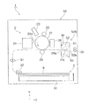
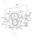
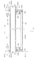
図1から図4は、実施の形態1に係る定着装置を用いた画像形成装置等を示すものである。図1はその画像形成装置の内部の概要を示し、図2はその定着装置の一端部側から見た状態を示し、図3はその定着装置の内部の状態を示し、図4はその定着装置の構成を一部断面として示している。図1等の図面における符号X,Y,Zの矢印は、各図面において想定した3次元空間の幅、高さ及び奥行の各方向を示す直交座標軸(の方向)である。
[Embodiment 1]
1 to 4 show an image forming apparatus using the fixing device according to the first embodiment. 1 shows an outline of the inside of the image forming apparatus, FIG. 2 shows a state viewed from one end side of the fixing device, FIG. 3 shows an internal state of the fixing device, and FIG. 4 shows the fixing device. Is partially shown in cross section. The arrows X, Y, and Z in drawings such as FIG. 1 are orthogonal coordinate axes (directions) indicating the respective directions of the width, height, and depth of the three-dimensional space assumed in each drawing.
<画像形成装置の全体の構成>
画像形成装置1は、図1に示されるように、装置本体である筐体10の内部に、現像剤からなる未定着像のトナー像を形成して記録媒体の一例としての記録用紙9に転写する画像形成部2、所要の記録用紙9を収容するとともに画像形成部2の転写位置に供給するよう送出する給紙装置3、記録用紙9に転写されるトナー像を定着する定着装置5等を備えている。筐体10は、構造材、支持材、外装材等の各種部材で構成されている。
<Overall Configuration of Image Forming Apparatus>
As shown in FIG. 1, the
画像形成部2は、矢印で示す方向に回転駆動する感光体の一例としての感光ドラム21と、感光ドラム21の表面(像形成領域となる外周面部分)を所要の電位に帯電させる帯電装置22と、感光ドラム21の帯電後の表面に画像情報(信号)に基づく光を照射して露光することにより静電潜像を形成する露光装置23と、その感光ドラム21上の静電潜像を現像剤により現像してトナー像にする現像装置24と、その感光ドラム21上のトナー像を記録用紙9に転写する転写装置25と、転写後の感光ドラム21の表面に残留するトナー等の不要物を除去して清掃する清掃装置26とで主に構成されている。
The
給紙装置3は、画像の形成に使用する所要のサイズ、種類等からなる複数枚の記録用紙9を積み重ねた状態で収容する用紙収容体31と、その用紙収容体31に収容される記録用紙9を1枚ずつ送り出す送出装置32とを備えて構成されている。用紙収容体31は、筐体10に対して引き出した状態にできるよう取り付けられており、その利用する態様に応じて複数装備される。図1における一点鎖線は、筐体10内における記録用紙9の主な用紙搬送路を示す。その用紙搬送路は、複数の搬送ロール対34,35や図示しない複数の搬送ガイド部材等で構成されている。
The
定着装置5は、図1、図2等に示されるように、導入口50a及び排出口50bが設けられた筐体50の内部に、矢印で示す方向に回転駆動するとともに表面温度がハロゲンヒータ等の加熱手段52により所要の温度に加熱されて保持される加熱ロール51と、この加熱ロール51の回転軸線方向Jにほぼ沿うように所要の圧力で接触して従動回転するロール形態、ベルト−パット形態等の加圧回転部材53等を備えたものである。この定着装置5は、加熱ロール51と加圧回転部材53とが接触する圧接部FNが、未定着のトナー像が転写された記録用紙9を挟んだ状態で通過させて所要の定着処理(加熱及び加圧)を行う定着処理部として構成されている。
定着装置5の詳細については後述する。
As shown in FIGS. 1 and 2, etc., the fixing
Details of the fixing
そして、画像形成装置1による画像形成は、次のようにして行われる。ここでは代表して、記録用紙9の片面に画像を形成するときの基本的な画像形成動作を説明する。
Then, image formation by the
画像形成装置1は、画像形成動作の開始指令を受けると、画像形成部2において、回転始動する感光ドラム21の表面が帯電装置22により所定の極性及び電位に帯電された後、その感光ドラム21の帯電した表面に露光装置23により画像情報に基づく露光が行われて所要の電位からなる静電潜像が形成される。続いて、感光ドラム21に形成された静電潜像が、現像装置24を通過する際に現像ロール24aを介して供給される所要の極性に帯電されたトナーにより現像されてトナー像として顕像化される。
When the
しかる後、感光ドラム21上に形成されたトナー像は、感光ドラム21の回転により転写装置25と対向する転写位置まで搬送されると、このタイミングに合わせて給紙装置3から用紙搬送路を経由して転写位置まで供給される記録用紙9の片面に対し、転写装置25の転写作用により転写される。この転写後の感光ドラム21の表面は、清掃装置26により清掃される。
Thereafter, when the toner image formed on the
続いて、トナー像が転写された記録用紙9は、画像形成部2の感光ドラム21から剥離された後に定着装置5に導入されるよう搬送される。定着装置5においては、その記録用紙9が筐体50の導入口50aを通して加熱ロール51と加圧回転部材53との間の圧接部(定着処理部)FNに挟まれるよう導入されて通過するが、その通過の際に定着処理されることにより未定着のトナー像が加圧下で溶融して記録用紙9に定着される。この定着が終了した後の記録用紙9は、定着装置5から筐体50の排出口50bを通して排出されて用紙搬送路を経由するよう搬送され、最後に筐体10の外部等に設けられる図示しない収容部に収容される。
Subsequently, the recording paper 9 onto which the toner image has been transferred is transported so as to be introduced into the fixing
以上により、1枚の記録用紙9の片面に対して1色のトナーで構成される単色画像が形成され、画像形成装置1による基本的な画像形成動作が終了する。複数枚の画像形成動作を実行する指令が出された場合には、上記した一連の動作がその枚数分だけ同様に繰り返されることになる。
As described above, a single color image composed of one color toner is formed on one side of one recording sheet 9, and the basic image forming operation by the
<定着装置の構成>
上記定着装置5は、図2から図4等に示されるように、前述した加熱ロール51及び加熱手段52が筐体50の一部である板状の側面支持材501,502に取り付けられており、前述した加圧回転部材53が筐体50の一部である一対の揺動支持材503に取り付けられている。
<Configuration of fixing device>
As shown in FIGS. 2 to 4 and the like, the fixing
このうち側面支持材501,502は、連結支持材504等により連結された状態に保たれている。また、一対の揺動支持材503は、図3等に示されるように、加圧回転部材53を下方側から支持する中央付近が窪むように曲がった形状からなる一対のフレームである。この各揺動支持材503は、その加圧回転部材53を挟んで一方に突出する一端部が、側面支持材501,502の内面側に設けられた支持突部505に対して両矢印で示す方向に回動自在な状態になるよう取り付けられている。さらに、各揺動支持材503は、その加圧回転部材53を挟んで他方に突出する他端部が、加圧用バネ506により加熱ロール51側に変位するよう加圧された状態になるよう取り付けられている。加圧用バネ506は、その下端部が側面支持材501,502の一部に接触し、その上端部が揺動支持材503の他端部の下面に接触した状態で配置される。図3における符号507は、揺動支持材503の上方への揺動範囲の限界位置を規制する規制突起を示す。
Of these, the side support members 501 and 502 are kept in a state of being connected by a
また、側面支持材501,502については、そのいずれも下部側面支持材501A,502Aと上部側面支持材501B,502Bとに分割されており、その下部側面支持材501A,502Aの上部片側に設けられた支持軸508を中心に回動して上部側面支持材501B,502Bを上方に持ち上げて開いた状態にできる構成になっている。上部側面支持材501B,502Bの下部中央には、加熱ロール51の両端(後述する円筒状部分の支持部材)を嵌め入れて装着する逆U字状の装着孔(上方に切り込まれた切り欠き溝)510が形成されている。図2と図3における符号509は、閉じた状態にしたときの上部側面支持材501B,502Bと下部側面支持材501A,502Aとを固定しておくためのネジを示す。
The side support members 501 and 502 are each divided into lower
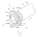
加熱ロール51は、アルミニウム、他の金属材料等の材料からなる円筒状のロール基体512と、そのロール基体512の両端部における一定の領域を除く外周面に形成される表面層513等で構成されている。加熱ロール51は、その一方の端部51bにギヤ(はすば歯車)517が固定した状態で取り付けられており、そのギヤ517に図示しない回転駆動装置から回転動力が伝達されて矢印Aで示す方向に所要の速度で回転駆動するようになっている。
The
実施の形態1における加圧回転部材53は、ベルト−パット形態の加圧回転部材を適用している。このベルト−パット形態の加圧回転部材53は、図3等に示されるように、加熱ロール51の外周面に接触して回転する無端状の定着ベルト531と、定着ベルト531の内周面側に配置されて定着ベルト531の外周面を加熱ロール51の外周面に押し付けて圧接部FNを形成する押圧パット532と、定着ベルト531を回転自在に支持するとともに押圧パット532を加熱ロール51側に向けて加圧する状態で支持する支持構造体533等で構成されている。支持構造体533は、揺動支持材503に固定されている。図4においては加熱手段52や押圧パット532の図示を省略している。
The
そして、この定着装置5においては、加熱ロール51としてロール基体512の肉厚が比較的薄い(例えば0.3mm以上2.0mm以下の厚さ)を適用するため、その加熱ロール51を回転自在に支持する装置として以下の構成からなるロール支持装置4を適用している。
In the
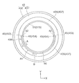
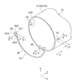
すなわち、ロール支持装置4は、図2から図8等に示されるように、加熱ロール51を2つの貫通孔42が設けられた円筒状部分515を少なくとも有する構造からなる加熱ロールとしたうえで、その加熱ロール51と、加熱ロール51の外周面の各貫通孔42に接近した部分に取り付けられて加熱ロール51を回転自在に支持する支持部材43と、加熱ロール51の各貫通孔42を通して円筒状部分515の内周面側に入り込むよう延びてから円筒状部分515の内周面のうち各貫通孔42の周囲になる一部分に対峙するよう曲げられた形状の引っ掛け曲げ部45と、加熱ロール51の外周面の周方向に沿うよう存在して支持部材43と接触し得る接触部46とを有する構造からなり、接触部46との接触により支持部材43が加熱ロール51の回転軸線の一方向(J1)へ移動することを制止して支持部材43の位置を規制する規制部材44とを備えた装置である。
That is, the
加熱ロール51は、その全体が円筒状の形態からなるものであるが、実施の形態1ではロール基体512の表面層513が形成されていない部位(両端部)を上記円筒状部分515としている。また、加熱ロール51は、その円筒状部分515の外周面における半周の両端になる2地点に貫通孔42を1つずつ(計2つ)設けている。貫通孔42が設けられる円筒状部分515は、加熱ロール51を少なくとも回転自在に支持するために使用される部位となる。
加熱ロール51は、特にギヤ517が取り付けられていない端部51a側をロール支持装置4により支持すればよいが、実施の形態1では加熱ロール51のギヤ517が取り付けられている端部51b側もそのギヤ517を追加した状態でロール支持装置4により支持するよう構成している(図4)。
The
The
2つの貫通孔42はいずれも、加熱ロール51の回転軸線方向Jに沿って延びる開口形状からなる長孔である。実施の形態1における貫通孔42の開口形状は、加熱ロール51の回転軸線方向Jに沿う状態になる長辺を有する長方形としている。
Each of the two through
支持部材43は、筐体50の一部である側面支持材501,502において加熱ロール51を回転自在に支持するための部材である。実施の形態1における支持部材43は、加熱ロール51を回転自在に支持する軸受部材431と、軸受部材431と加熱ロール51の外周面との間に少なくとも介在して配置される断熱性部材435とで構成されている。
The
支持部材43における軸受部材431は、例えばラジアル軸受で構成されている。また、軸受部材431は、そのラジアル軸受を構成する内輪に、その内輪が加熱ロール51の円筒状部分515の外周面に隙間をあけた状態で取り付けられるようにする空間S1が形成されている。さらに、軸受部材431は、そのラジアル軸受を構成する外輪の外周面に、その周方向にわたって存在して軸受部材431の装着時に側面支持材501,502の一部(装着孔の周辺部)に突き当ることで加熱ロール51の回転軸線方向Jにおける位置決めを行う連続した突部432が設けられている。
The bearing
支持部材43における断熱性部材435は、加熱ロール51の円筒状部分515の外側と軸受部材431との間の隙間(軸受部材431の空間S1のうち円筒状部分515を除く部分)に嵌め入れられる肉厚からなる円筒状の本体部436と、本体部436の外周面の一端にその周方向にわたって設けられて断熱性部材435の装着時に軸受部材431に接触することで加熱ロール51の回転軸線方向Jにおける支持部材43の位置決めを行うフランジ(鍔部)437とで構成されている。
本体部436は、その内側に加熱ロール51の円筒状部分515の外側に嵌め合わせて取り付けるための空間S2が形成されており、また、その外径が軸受部材431の空間S1に嵌め入れることが可能な寸法に設定されている。また、実施の形態1における断熱性部材435は、フランジ437を含む本体部436の周方向の一部が切除された切除部438を有した形状の部材として構成されている。なお、断熱性部材435は、加熱ロール51の円筒状部分515の外周面に対して固定されず、相対的に移動し得る状態になっている。
この断熱性部材435は、加熱ロール51の加熱時の熱が軸受部材431に伝わることを遮断することができる程度の断熱性を有する部材であればよく、例えば、断熱性を発揮する合成樹脂等の断熱性材料を用いて製作される。
The
The
The
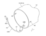
規制部材44は、上記した引っ掛け曲げ部45と接触部46とを有する構造からなり、その接触部46との接触により支持部材43が加熱ロール51の回転軸線方向Jにおける一方の方向(一方向)J1へ移動することを制止するものである。実施の形態1における規制部材44は、2つの端部を有する円弧状の部材からなり、その2つの端部を少なくとも引っ掛け曲げ部45として構成したものである。
The restricting
より具体的には、規制部材44は、鉄などの金属材料等の材料からなる所要の長さの線材(線状部材)を用いて例えば以下のようにして製作される。
最初に、その線材の両端部を除く中央側の主要部分を、図5から図9等に示されるように、加熱ロール51の円筒状部分515の外径とほぼ同じ曲率でもって半円弧状に曲げた形状に成形することで、その全体を接触部46とする。
また、その線材の両端部を、接触部46の半円弧の外側(換言すると加熱ロール51の円筒状部分515の法線方向)に開いて立ち上げるよう曲げてから(以上の曲げ部分を「第1曲げ部451」とする)、接触部46の半円弧と直交する方向(換言すると加熱ロール51の回転軸線方向J)に沿って曲げた後(以上の曲げ部分を「第2曲げ部452」とする)、接触部46の半円弧の内側(換言すると加熱ロール51の円筒状部分515の内側又は回転中心)に向けて曲げてから(以上の曲げ部分を「第3曲げ部453」とする)、最後に、第2曲げ部452と同様に接触部46の半円弧と直交する同じ方向に曲げた(以上の曲げ部分を「最終曲げ部454」とする)形状に成形することで、以上の各曲げ部451〜454をもって引っ掛け曲げ部45とする。
この引っ掛け曲げ部45の場合は、最終曲げ部454が、円筒状部分515の内周面のうち貫通孔42の周囲部分(516)の一部に対峙して実際に引っ掛かり得る引っ掛け部分として機能することになる。また、この最終曲げ部454は、例えば、その終端が加熱ロール51の両端(51a,51b)の近い方の端部(51aなど)に向くように使用される。図9において二点鎖線で囲まれる領域516は、円筒状部分515の内周面のうち貫通孔42の周囲になる部分の一例を示す。
More specifically, the regulating
First, the main part on the center side excluding both ends of the wire is formed in a semicircular arc shape with substantially the same curvature as the outer diameter of the
Further, both ends of the wire are bent so as to open and rise outside the semicircular arc of the contact portion 46 (in other words, in the normal direction of the
In the case of the hooked
また、この規制部材44の引っ掛け曲げ部45と加熱ロール51における各貫通孔42との寸法関係は、次のように設定されている(図9)。
まず、貫通孔42における回転軸線方向Jに沿う長辺の長さL1は、引っ掛け曲げ部45の最終曲げ部454を通して貫通孔42に差し込むことを可能にする必要があることから、少なくとも最終曲げ部454の長さE1よりも少し長めの寸法に設定される。次に、貫通孔42における回転軸線方向Jと直交する短辺の長さL2は、引っ掛け曲げ部45の少なくとも第3曲げ部453及び最終曲げ部454を通して貫通孔42に差し込むことを可能にする必要があることから、少なくとも第3曲げ部453及び最終曲げ部454の太さDよりも少し広めの寸法に設定される。一方、引っ掛け曲げ部45における第3曲げ部453の長さE2は、最終曲げ部454が貫通孔42を通過して円筒状部分515の内周面側に存在した状態にする必要があることから、少なくとも円筒状部分515の肉厚や最終曲げ部454の太さDなどを合算した寸法よりも大きい寸法に設定される。
また、規制部材44における接触部46の半円弧の長さは、規制部材44の両端に存在する2つの引っ掛け曲げ部45が加熱ロール51における各貫通孔42に到達してその各引っ掛け曲げ部45を各貫通孔42にそれぞれ差し込んで取り付けることが可能になる寸法に設定される。
Further, the dimensional relationship between the hooked bending
First, since the length L1 of the long side along the rotation axis direction J in the through
Further, the length of the semicircular arc of the
定着装置5におけるロール支持装置4は、例えば、次のようにして組み立てられる。
The
まず、図10(a)に示すように、加熱ロール51の一端部51a側における円筒状部分515に、支持部材43の軸受部材431及び断熱性部材435を嵌め入れる。また、加熱ロール51の他端部51b側における円筒状部分515に、支持部材43の軸受部材431及び断熱性部材435を嵌め入れた後、その円筒状部分515の支持部材43の外側にギヤ517を嵌め合わせる。
First, as shown in FIG. 10A, the bearing
続いて、図10(b)に例示するように、加熱ロール51の両端部51a,51bにある各円筒状部分515における各貫通孔42に対し、規制部材44における2つの引っ掛け曲げ部45を円筒状部分515の外周面側からそれぞれ差し込む。
この段階では、各規制部材44は、その引っ掛け曲げ部45の最終曲げ部454が貫通孔42を単に通過して円筒状部分515の内周面側に存在した状態におかれただけとなる。換言すれば、規制部材44は、その引っ掛け曲げ部45の最終曲げ部454が円筒状部分515の内周面のうち各貫通孔42の周囲になる一部分516に対峙しておらず、また、その接触部46が支持部材43における断熱性部材435のフランジ437に接触していない状態になっている(図10(b))。但し、この段階では、規制部材44における接触部46は、円筒状部分515の外周面に接触した状態になる。
Subsequently, as illustrated in FIG. 10B, the two hooked
At this stage, each regulating
続いて、加熱ロール51の両端部51a,51bにある各円筒状部分515に嵌め入れられている支持部材43の軸受部材431及び断熱性部材435を、加熱ロール51の各両端部51a,51bに向けてそれぞれ変位させ、規制部材44によって制止される位置まで移動させる。例えば、図8において側面支持材501A,501Bを除いた状態にする。
この際、支持部材43の移動により、規制部材44も次のように変位する。すなわち、その移動する支持部材43における断熱性部材435のフランジ437が規制部材44の接触部46に突き当たることで、規制部材44全体が加熱ロール51の各端部51a,51bに向けて各円筒状部分515の外周面上を変位させられる。これにより、規制部材44の引っ掛け曲げ部45における第3曲げ部453が各貫通孔42の加熱ロール51の両端51a,51b側に位置する短辺の部分42a(図10(b))に押し付けられた状態になる。この状態になることで規制部材44の上記変位が停止する。
Subsequently, the bearing
At this time, the movement of the
最後に、この支持部材43及び規制部材44を取り付けた状態の加熱ロール51を、定着装置5の筐体50において開けた状態にした上部側面支持材501B,502Bの装着部(装着孔510)に嵌め入れて取り付ける。
詳しくは、加熱ロール51は、その各円筒状部分515にある支持部材43の軸受部材431における突出部432が上部側面支持材501B,502Bの装着孔510の周辺部分に接触した状態になるよう(図8)、その支持部材43の軸受部材431及び断熱性部材435を介してその装着孔510内に嵌め入れられる。この装着孔510への嵌め入れ作業が終了した後は、上部側面支持材501B,502Bを閉じた状態にし、ネジ509により下部側面支持材501A,502Aに固定する(図2)。
Finally, the
Specifically, in the
この結果、規制部材44は、図4、図6、図8等に示されるように、その引っ掛け曲げ部45の最終曲げ部454が貫通孔42から入り込んで円筒状部分515の内周面のうち貫通孔42の周囲部分516の一部に対峙した状態になり、また、その接触部46が支持部材43における断熱性部材435のフランジ437に接触した状態(又は接触し得る状態)になる。
As a result, as shown in FIGS. 4, 6, 8, and the like, the regulating
以上の工程作業により、図2、図4、図8等に示されるように、定着装置5における加熱ロール51を回転自在に支持するロール支持装置4が組み立てられる。
Through the above process operations, as shown in FIGS. 2, 4, 8, and the like, the
そして、このロール支持装置4を適用した定着装置5においては、図4等に示されるように、加熱ロール51がその両端51a,51bにある円筒状部分515において支持部材43により回転自在に支持される。
具体的には、支持部材43の断熱性部材435が加熱ロール51の円筒状部分515の外周面に嵌め合わされて原則として一体化された状態になる。これにより、加熱ロール51は、断熱性部材435を介して支持部材43の軸受部材431により回転自在に支持されることになる。
一方、ベルト−パット形態の加圧回転部材53は、一対の揺動支持材503に回転自在に支持されるとともに加圧用バネ506によるばね力を受けて加熱ロール51の回転軸線方向Cにほぼ沿う状態で圧接される。この圧接により、定着装置5では加熱ロール51と加圧回転部材53との間に圧接部FNが形成される(図3)。
In the
Specifically, the
On the other hand, the pressure-rotating
また、この定着装置5においては、画像形成動作等の稼働時になると、加熱ロール51がギヤ517から回転動力を受けることにより矢印Aで示す方向に回転駆動する。
この際、加熱ロール51は、その両端51a,51bに存在する円筒状部分515が支持部材43に支持された状態で回転する。詳しくは、加熱ロール51は、支持部材43における断熱性部材435と一体になった状態で同じ方向Aに回転し、その断熱性部材435が支持部材43における軸受部材431に対して回転自在に支持された状態になって回転する。またこのとき、規制部材44も、加熱ロール51と一体になって同じ方向Aに回転する。
In the
At this time, the
さらに、この定着装置5においては、支持部材43の断熱性部材435が加熱ロール51の回転軸線方向の一方向J1へ移動(変位)しようとした場合、その断熱性部材435の一部(フランジ437)が加熱ロール51の円筒状部分515に固定されるように取り付けられた規制部材44の接触部46と接触することにより阻止され、支持部材43の回転軸線方向Jに対する取り付け位置が規制される。
つまり、規制部材44は、図8に示されるように、その2つの引っ掛け曲げ部45が円筒状部分515における各貫通孔42に差し込まれて貫通孔の一方の短辺42aに押し当てられているため、回転軸線方向の一方向J1への移動が阻止されて位置が固定されている。このため、その規制部材44の接触部46に接触する支持部材43の断熱性部材435は、その回転軸線方向の一方向J1への移動が阻止されることになる。
Further, in the
That is, as shown in FIG. 8, the two hooked
これにより、定着装置5では、例えば、加熱ロール51に回転動力を伝達するギヤ517がはすば歯車の場合におけるスラスト方向に発生する分力の成分や、圧接部FNにおける圧力バランスの影響により一時的に発生するスラスト方向への力が生じた場合であっても、規制部材44により支持部材43の回転軸線方向の一方向J1への移動を阻止することができる。
Thereby, in the
そして、この定着装置5においては、ロール支持装置4における支持部材43の断熱性部材435が加熱ロール51と一体に回転せず一時的に停止した状態又は減速して回転する状態になった場合、図7等に例示するように、加熱ロール51と一体に回転する規制部材44の接触部46とその状態の断熱性部材435との間で摺擦(相対的に異なる方向へ接触して移動することによる擦れ)が発生する。これにより、その規制部材44の接触部46に対して、図6や図7に矢印Bで例示するような加熱ロール51の回転方向Aとは反対側に向く外力(F1)がおよぶことになる。この外力(F1)は、規制部材44に対し、その規制部材44を加熱ロール51の円筒状部分515から外すような力として作用する。
In the
しかし、ロール支持装置4における規制部材44は、特に引っ掛け曲げ部45が円筒状部分515における貫通孔42に差し込まれているだけでなく、その一部(最終曲げ部454)が円筒状部分515の内周面のうち貫通孔42の周囲の一部分に対峙して引っ掛かるような状態になるため、引っ掛け曲げ部45が円筒状部分515における貫通孔42から抜けることがない。
したがって、規制部材44は、断熱性部材435との間で摺擦により上記外力(F1)がおよんでも、加熱ロール51の円筒状部分515から外れてしまうおそれがない。
However, the restricting
Therefore, the regulating
これに対し、ロール支持装置4において、上記規制部材44に代えて、図13や図14(a)に例示するように、加熱ロール51に設ける貫通孔420に嵌め入れるために内側に突出するよう曲げたのみの突出部445を有する規制部材440を適用した場合は、以下に説明するように、その規制部材440が加熱ロール51から外れることがある。この規制部材440の場合における貫通孔420は、加熱ロール51の回転軸線方向Jと直交する周方向に延びる開口形状からなる長孔になる。
つまり、規制部材440は、前述した状況により支持部材43(断熱性部材435)との間で摺擦が発生すると、その規制部材440に加熱ロール51の回転方向Aとは反対側の方向Bに向く外力(F1)がおよぶ。これにより、規制部材440は、円弧状の規制部材440は円弧の外側に開くような状態になり、図14(b)に例示するようにその突出部445が貫通孔420から抜き出されて加熱ロール51の外周面上に乗り上げるようになる。この結果、規制部材440は加熱ロール51から外れてしまう。
In contrast, in the
That is, when the regulating
[他の実施の形態]
図11は、ロール支持装置4における規制部材44の他の構成からなる規制部材44Bを示すものである。
この規制部材44Bは、実施の形態1における規制部材44に対し、円弧状の接触部46のほぼ中間位置に内側に突出するように曲がって突出する差込み部47を追加して設けた点で異なるものである。また、この規制部材44Bを適用する加熱ロール51の円筒状部分515には、実施の形態1における貫通孔42の他に、上記差込み部47が挿しこまれる3つ目の貫通孔42Bを設けている。この貫通孔42Bは、貫通孔42の場合と異なり、加熱ロール51の回転軸線方向Jと直交する周方向に延びる開口形状からなる長孔になる。また、貫通孔42Bは、規制部材44Bの取り付け時に前記したような支持部材43の両端側への各移動を要する分だけ、加熱ロール51の回転軸線方向Jにおいて少し広めに形成される。
[Other embodiments]
FIG. 11 shows a regulating
The
そして、この規制部材44Bを適用するロール支持装置4においては、規制部材44Bの取り付けは、その両端にある2つの引っ掛け曲げ部45を貫通孔42に前述したように差し入れるとともに、その中央部にある1つの差込み部47を円筒状部分515の外周面側から貫通孔42Bに差し込む。これにより、規制部材44Bは、その接触部46が加熱ロール51の円筒状部分515に接触又は接近した状態になる。
この結果、規制部材44Bは、加熱ロール51の円筒状部分515に対し、2つの引っ掛け曲げ部45による支持(2点での支持)に、1つの差込み部47による支持が追加されて計3点で支持されるよう取り付けられる。このため、この規制部材44Bを適用した場合には、規制部材44Bによる支持部材43の回転軸線方向の一方向J1への移動の制止がより安定して行われるようになる。また、この規制部材44Bは、加熱ロール51の周方向への変位が差込み部47による支持が追加されて更に強固に規制されるようになるので、支持部材43の断熱性部材435との摺擦が発生した場合でも、加熱ロール51から更に外れにくくなる。
In the
As a result, the restricting
実施の形態1では、ロール支持装置4を定着装置5に適用した場合を例示したが、このロール支持装置4は、その他にも例えば、図12に例示するように、貫通孔が設けられた円筒状部分を少なくとも有する構造からなる回転搬送ロール61と、その回転搬送ロール61と接触して記録用紙9等の被搬送物90を挟んで搬送する接触部Nを形成しながら回転するロール形態、ベルト形態等の回転部材63とを備えた搬送装置6における回転搬送ロール61を回転自在に支持する装置として適用することができる。
このような搬送装置6は、画像形成装置1や他の装置に使用されるものである。画像形成装置1に使用される搬送装置6は、例えば、記録用紙9の反り状態を矯正するロール搬送式の搬送装置であってもよい。なお、回転搬送ロール61は、ベルトの支持ロールであっても構わない。
In the first embodiment, the case where the
Such a transport device 6 is used in the
また、ロール支持装置4に適用される加熱ロール51、回転搬送ロール61等のロールとしては、その貫通孔42が設けられる円筒状部分515以外の部位については肉厚が厚めの構造のロール部分や、内部が空洞でない中実構造のロール部分であってもよい。また、円筒状部分515は、ロールの端部付近に存在せず、ロール端部から少し中央部寄りの内側の位置に配置されるものであっても構わない。
Moreover, as rolls, such as the
また、ロール支持装置4に適用される支持部材43としては、軸受部材のみから構成されるものであってもよい。また、ロール支持装置4に適用される規制部材44は、その接触部46について、支持部材43との接触が可能であれば、線状の形状のものでなく、他の形状からなる接触部として構成してもよい。また、規制部材44としては、引っ掛け曲げ部45の円筒状部分515の内周面側における最終曲げ部454の曲げる方向について、円筒状部分515の内周面のうち貫通孔42の周囲部分516の一部と対峙すれば、他の方向に変更しても差し支えない。
Moreover, as the
ロール支持装置4を適用する定着装置は、実施の形態1に係る定着装置5の構成例に限定されず、例えば、その加熱ロール51の加熱手段52として他の方式の加熱手段(例えば電磁誘導加熱式の手段)を適用したり、その加圧回転部材53としてロール形態のものを適用したものであってもよい。
The fixing device to which the
この他、本発明が適用される画像形成装置は、実施の形態1で例示した単色の画像(白黒画像)を形成する形式の画像形成装置に限定されず、この他にも例えば、複数色のトナー像を形成する複数の画像形成部2を備えて多色画像(カラー画像)を形成する多色画像(カラー画像)を形成する形式の画像形成装置であっても構わない。このカラー画像を形成する画像形成装置の場合は、必要に応じて、複数の画像形成部2で形成される各色のトナー像を一時的に一次転写して最終的に記録用紙9に二次転写する機能を有する中間転写装置を適用することができる。また、上記搬送装置6を適用する画像形成装置は、現像剤で構成される画像を形成するものに限らず、他の構成からなる画像を形成する画像形成部2を有する画像形成装置であってもよい。
In addition, the image forming apparatus to which the present invention is applied is not limited to the image forming apparatus of the type that forms the monochrome image (monochrome image) exemplified in the first embodiment. An image forming apparatus of a type that includes a plurality of
1 …画像形成装置
2 …画像形成部
4 …ロール支持装置
5 …定着装置
6 …搬送装置
42,42B…貫通孔
43…支持部材
431…軸受部材
435…断熱性部材
44,44B…規制部材
45…引っ掛け曲げ部
46…接触部
51…加熱ロール
52…加熱手段
515…円筒状部分
516…周囲部分(円筒状部分の内周面のうち貫通孔の周囲になる部分)
53…加圧回転部材
61…回転搬送ロール(回転部材)
62…回転体
9 …記録用紙(記録媒体)
90…被搬送物
FN,N…圧接部
J1…回転軸線一方向
DESCRIPTION OF
53 ...
62: Rotating body 9: Recording paper (recording medium)
90 ... conveyed object FN, N ... pressure contact part J1 ... one direction of rotation axis
Claims (9)
前記ロールの外周面の前記貫通孔に接近した部分に取り付けられて前記ロールを回転自在に支持する支持部材と、
前記ロールの前記貫通孔を通して前記円筒状部分の内周面側に入り込むよう延びてから前記円筒状部分の内周面のうち前記貫通孔の周囲になる一部分に対峙するよう曲げられた形状の引っ掛け曲げ部と、前記ロールの外周面の周方向に沿うよう存在して前記支持部材と接触し得る接触部とを有する構造からなり、前記接触部との接触により前記支持部材が前記ロールの回転軸線の一方向へ移動することを制止して前記支持部材の位置を規制する規制部材と、
を備えるロール支持装置。 A roll having a structure having at least a cylindrical portion provided with a through hole;
A support member attached to a portion of the outer peripheral surface of the roll that is close to the through-hole and rotatably supporting the roll;
A hook having a shape that extends so as to enter the inner peripheral surface side of the cylindrical portion through the through hole of the roll and then is bent so as to face a portion of the inner peripheral surface of the cylindrical portion surrounding the through hole. It has a structure having a bent portion and a contact portion that exists along the circumferential direction of the outer peripheral surface of the roll and can come into contact with the support member. A restricting member for restricting the position of the support member by stopping movement in one direction;
A roll support device comprising:
前記規制部材の引っ掛け曲げ部が前記2以上の貫通孔に対応して2以上設けられている請求項1に記載のロール支持装置。 Two or more through holes are provided in the circumferential direction of the cylindrical portion,
The roll support device according to claim 1, wherein two or more hooked and bent portions of the regulating member are provided corresponding to the two or more through holes.
前記規制部材の引っ掛け曲げ部が前記ロールの両端部のうち前記貫通孔に近い方の端部に向けて曲げられている請求項1又は2に記載のロール支持装置。 The through hole is a long hole having an opening shape extending along the rotation axis direction of the roll,
The roll support device according to claim 1 or 2, wherein a hooked bending portion of the regulating member is bent toward an end portion closer to the through hole among both end portions of the roll.
前記回転ロールと接触して被搬送物を挟んで搬送する接触部を形成しながら回転する回転部材と、
を備え、
前記回転ロールが請求項1乃至4のいずれかに記載のロール支持装置により支持されている搬送装置。 A rotating roll having a structure having at least a cylindrical portion provided with a through-hole, and rotationally driven;
A rotating member that rotates while forming a contact portion that contacts the rotating roll and conveys the object to be conveyed;
With
The conveyance apparatus with which the said rotation roll is supported by the roll support apparatus in any one of Claims 1 thru | or 4.
前記加熱ロールと圧接して未定着像が転写された記録媒体を挟んで通過させる圧接部を形成しながら回転する加圧回転部材と、
を備え、
前記加熱ロールが請求項1乃至4のいずれかに記載のロール支持装置により支持されている定着装置。 A structure comprising at least a cylindrical portion provided with a through-hole, a heating roll that is rotated and heated by a heating means;
A pressure rotating member that rotates while forming a pressure contact portion that sandwiches and passes the recording medium onto which the unfixed image is transferred by pressure contact with the heating roll;
With
A fixing device in which the heating roll is supported by the roll support device according to claim 1.
前記規制部材の接触部は前記断熱性部材に接触する請求項6に記載の定着装置。 The support member in the roll support device includes a bearing member that rotatably supports the heating roll, and a heat insulating member that is disposed at least between the bearing member and the outer peripheral surface of the heating roll. Has been
The fixing device according to claim 6, wherein a contact portion of the regulating member contacts the heat insulating member.
前記搬送装置が請求項5に記載の搬送装置で構成されている画像形成装置。 An image forming unit that forms an unfixed image and transfers the unfixed image to a recording medium, and a conveying device that conveys the recording medium across the recording medium,
An image forming apparatus comprising the transport device according to claim 5.
前記定着装置が請求項6又は7に記載の定着装置で構成されている画像形成装置。 An image forming unit that forms an unfixed image and transfers it to a recording medium; and a fixing device that fixes the unfixed image transferred to the recording medium in the image forming unit,
An image forming apparatus comprising the fixing device according to claim 6 or 7.
Priority Applications (3)
| Application Number | Priority Date | Filing Date | Title |
|---|---|---|---|
| JP2015243371A JP6638367B2 (en) | 2015-12-14 | 2015-12-14 | Roll support device, transport device using the support device, fixing device, and image forming device |
| US15/130,388 US9835994B2 (en) | 2015-12-14 | 2016-04-15 | Roller support device, transport device including the support device, fixing device including the support device, and image forming apparatus including the support device |
| CN201610397961.XA CN106873333B (en) | 2015-12-14 | 2016-06-07 | Roller supporting device, conveying device, fixing device and image forming apparatus |
Applications Claiming Priority (1)
| Application Number | Priority Date | Filing Date | Title |
|---|---|---|---|
| JP2015243371A JP6638367B2 (en) | 2015-12-14 | 2015-12-14 | Roll support device, transport device using the support device, fixing device, and image forming device |
Publications (2)
| Publication Number | Publication Date |
|---|---|
| JP2017111197A true JP2017111197A (en) | 2017-06-22 |
| JP6638367B2 JP6638367B2 (en) | 2020-01-29 |
Family
ID=59020411
Family Applications (1)
| Application Number | Title | Priority Date | Filing Date |
|---|---|---|---|
| JP2015243371A Expired - Fee Related JP6638367B2 (en) | 2015-12-14 | 2015-12-14 | Roll support device, transport device using the support device, fixing device, and image forming device |
Country Status (3)
| Country | Link |
|---|---|
| US (1) | US9835994B2 (en) |
| JP (1) | JP6638367B2 (en) |
| CN (1) | CN106873333B (en) |
Families Citing this family (2)
| Publication number | Priority date | Publication date | Assignee | Title |
|---|---|---|---|---|
| JP6926901B2 (en) * | 2017-09-28 | 2021-08-25 | 京セラドキュメントソリューションズ株式会社 | Retaining structure, fixing device and image forming device |
| JP2022146165A (en) * | 2021-03-22 | 2022-10-05 | 京セラドキュメントソリューションズ株式会社 | Fixing device and image forming device equipped with fixing device |
Family Cites Families (11)
| Publication number | Priority date | Publication date | Assignee | Title |
|---|---|---|---|---|
| JPS6119265U (en) * | 1984-07-10 | 1986-02-04 | 富士ゼロックス株式会社 | Heated roller type fixing device |
| JPH09325634A (en) * | 1996-06-05 | 1997-12-16 | Ricoh Co Ltd | Fixing device |
| JPH11219056A (en) * | 1997-10-23 | 1999-08-10 | Ricoh Co Ltd | Fixing device |
| JP4622224B2 (en) | 2003-10-01 | 2011-02-02 | 富士ゼロックス株式会社 | Insulating sleeve, fixing device using the same, and image forming apparatus |
| JP4207129B2 (en) | 2004-07-29 | 2009-01-14 | ブラザー工業株式会社 | Image forming apparatus |
| JP4493476B2 (en) * | 2004-11-22 | 2010-06-30 | 京セラミタ株式会社 | Belt drive |
| US7433643B2 (en) * | 2005-08-23 | 2008-10-07 | Kyocera Mita Corporation | Fixing device and image forming apparatus |
| JP5383868B2 (en) * | 2011-06-24 | 2014-01-08 | キヤノン株式会社 | Image heating apparatus and recording material conveying apparatus |
| JP5904748B2 (en) * | 2011-10-14 | 2016-04-20 | キヤノン株式会社 | Image heating device |
| CN104252123B (en) * | 2013-06-25 | 2016-08-17 | 株式会社理光 | Fixing device and image processing system |
| JP2015052687A (en) | 2013-09-06 | 2015-03-19 | キヤノン株式会社 | Heating device and fixing device |
-
2015
- 2015-12-14 JP JP2015243371A patent/JP6638367B2/en not_active Expired - Fee Related
-
2016
- 2016-04-15 US US15/130,388 patent/US9835994B2/en active Active
- 2016-06-07 CN CN201610397961.XA patent/CN106873333B/en active Active
Also Published As
| Publication number | Publication date |
|---|---|
| JP6638367B2 (en) | 2020-01-29 |
| CN106873333B (en) | 2019-12-24 |
| US20170168436A1 (en) | 2017-06-15 |
| CN106873333A (en) | 2017-06-20 |
| US9835994B2 (en) | 2017-12-05 |
Similar Documents
| Publication | Publication Date | Title |
|---|---|---|
| JP5530674B2 (en) | Circulating belt device, fixing device and image forming apparatus | |
| JP5499821B2 (en) | Conveying device, fixing device, and image forming apparatus | |
| JP2017111197A (en) | Roller support device, and conveying device using the support device, fixing device, and image forming apparatus | |
| JP6069889B2 (en) | Fixing device, image forming apparatus | |
| JP5982888B2 (en) | Fixing apparatus and image forming apparatus | |
| JP2017072645A (en) | Fixing device and image forming apparatus | |
| CN109240057B (en) | Fixing device and image forming apparatus | |
| JP5966993B2 (en) | Fixing apparatus and image forming apparatus | |
| JP5983957B2 (en) | Fixing apparatus and image forming apparatus | |
| JP6185873B2 (en) | Fixing apparatus and image forming apparatus | |
| JP4622224B2 (en) | Insulating sleeve, fixing device using the same, and image forming apparatus | |
| JP2014191039A (en) | Fixing device and image forming apparatus | |
| JP6182115B2 (en) | Fixing apparatus and image forming apparatus | |
| JP2017111198A (en) | Roller support device, and conveying device using the support device, fixing device, and image forming apparatus | |
| JP6471711B2 (en) | Fixing apparatus and image forming apparatus | |
| JP6376070B2 (en) | Intermediate transfer unit and image forming apparatus having the same | |
| JP2014170250A (en) | Fixing device and image forming apparatus including the same | |
| JP4238513B2 (en) | Insulating sleeve and fixing device using the same | |
| JP5008519B2 (en) | Fixing device, image forming apparatus, and frame | |
| CN107728449B (en) | Fixing device and image forming apparatus including the same | |
| JP6118742B2 (en) | Fixing apparatus and image forming apparatus | |
| JP2011203463A (en) | Conveying device, fixing device, and image forming apparatus | |
| JP6237601B2 (en) | Fixing apparatus and image forming apparatus | |
| JP2017003869A (en) | Fixing device and image forming apparatus | |
| JP2012203068A (en) | Sliding bearing, fixing device and image forming device |
Legal Events
| Date | Code | Title | Description |
|---|---|---|---|
| A621 | Written request for application examination |
Free format text: JAPANESE INTERMEDIATE CODE: A621 Effective date: 20181022 |
|
| A131 | Notification of reasons for refusal |
Free format text: JAPANESE INTERMEDIATE CODE: A131 Effective date: 20190716 |
|
| A977 | Report on retrieval |
Free format text: JAPANESE INTERMEDIATE CODE: A971007 Effective date: 20190717 |
|
| A521 | Request for written amendment filed |
Free format text: JAPANESE INTERMEDIATE CODE: A523 Effective date: 20190912 |
|
| TRDD | Decision of grant or rejection written | ||
| A01 | Written decision to grant a patent or to grant a registration (utility model) |
Free format text: JAPANESE INTERMEDIATE CODE: A01 Effective date: 20191126 |
|
| A61 | First payment of annual fees (during grant procedure) |
Free format text: JAPANESE INTERMEDIATE CODE: A61 Effective date: 20191209 |
|
| R150 | Certificate of patent or registration of utility model |
Ref document number: 6638367 Country of ref document: JP Free format text: JAPANESE INTERMEDIATE CODE: R150 |
|
| S533 | Written request for registration of change of name |
Free format text: JAPANESE INTERMEDIATE CODE: R313533 |
|
| R350 | Written notification of registration of transfer |
Free format text: JAPANESE INTERMEDIATE CODE: R350 |
|
| LAPS | Cancellation because of no payment of annual fees |