JP2017109672A - Headlight device of saddle-riding type vehicle - Google Patents
Headlight device of saddle-riding type vehicle Download PDFInfo
- Publication number
- JP2017109672A JP2017109672A JP2015247041A JP2015247041A JP2017109672A JP 2017109672 A JP2017109672 A JP 2017109672A JP 2015247041 A JP2015247041 A JP 2015247041A JP 2015247041 A JP2015247041 A JP 2015247041A JP 2017109672 A JP2017109672 A JP 2017109672A
- Authority
- JP
- Japan
- Prior art keywords
- lens
- light
- partition wall
- air intake
- headlight
- Prior art date
- Legal status (The legal status is an assumption and is not a legal conclusion. Google has not performed a legal analysis and makes no representation as to the accuracy of the status listed.)
- Granted
Links
Images


Landscapes
- Non-Portable Lighting Devices Or Systems Thereof (AREA)
- Lighting Device Outwards From Vehicle And Optical Signal (AREA)
Abstract
Description
本発明は、鞍乗り型車両のヘッドライト装置に関するものである。 The present invention relates to a headlight device for a saddle-ride type vehicle.
従来、例えば特許文献1に見られるように、光源(210)とリフレクタ(131)とが設けられたハウジング(130)と、このハウジング(130)の前面を覆うレンズ(120)とを有するヘッドライト(110)と、
前記レンズ(120)の周囲を覆い、レンズ(120)の照射面(120c)を前方に臨ませるためのライト開口部を有するフロントカウル(ハンドルアッシー100)とを備えた鞍乗り型車両のヘッドライト装置が知られている。
Conventionally, as can be seen, for example, in Patent Document 1, a headlight having a housing (130) provided with a light source (210) and a reflector (131) and a lens (120) covering the front surface of the housing (130). (110),
A headlight of a saddle-ride type vehicle including a front cowl (handle assembly 100) covering a periphery of the lens (120) and having a light opening for allowing the irradiation surface (120c) of the lens (120) to face forward. The device is known.
上述したような鞍乗り型車両のヘッドライト装置においては、フロントカウルの、ライト開口部近くに、走行風をヘッドライト後方へ取り入れるためのエア取り入れ口を設けることが要請される場合がある。
しかし、このような場合に、フロントカウルのライト開口部近くにエア取り入れ口を単に設けたのでは、ハウジング内の光源からの光がレンズを介してエア取り入れ口から外部へ漏れることがある。このようなエア取り入れ口からの光の漏れは、車両の外観を低下させて商品性を低下させる。
In the headlight device of a saddle-ride type vehicle as described above, it may be required to provide an air intake for taking in the traveling wind to the rear of the headlight near the light opening of the front cowl.
However, in such a case, if the air intake is simply provided near the light opening of the front cowl, the light from the light source in the housing may leak out from the air intake through the lens. Such light leakage from the air intake port deteriorates the appearance of the vehicle and the merchantability.
本発明が解決しようとする課題は、ライト開口部近くにエア取り入れ口を設けても、エア取り入れ口からの光の漏れを防止できる鞍乗り型車両のヘッドライト装置を提供することである。 The problem to be solved by the present invention is to provide a headlight device for a saddle-ride type vehicle that can prevent light leakage from the air intake even if an air intake is provided near the light opening.
上記課題を解決するために本発明の鞍乗り型車両のヘッドライト装置は、
光源とリフレクタとが設けられたハウジングと、このハウジングの前面を覆うレンズとを有するヘッドライトと、
前記レンズの周囲を覆い、レンズの照射面を前方に臨ませるためのライト開口部を有するフロントカウルとを備えた鞍乗り型車両のヘッドライト装置において、
前記フロントカウルの、ライト開口部近くに、走行風をヘッドライト後方へ取り入れるエア取り入れ口が設けられているとともに、
前記レンズの前面側に、前記ライト開口部とエア取り入れ口との間を仕切る仕切壁が設けられ、該仕切壁の先端から前記エア取り入れ口側のレンズの前面が黒く塗装され、
前記フロントカウルには、前記レンズの前面に向かって前記仕切壁の少なくとも片面に沿う対向壁が設けられていることを特徴とする。
この鞍乗り型車両のヘッドライト装置によれば、フロントカウルのライト開口部近くに設けられたエア取り入れ口によって、走行風をヘッドライト後方へ取り入れることができる。
そして、レンズの前面側に、ライト開口部とエア取り入れ口との間を仕切る仕切壁が設けられ、該仕切壁の先端からエア取り入れ口側のレンズの前面が黒く塗装され、さらに、フロントカウルには、レンズの前面に向かって仕切壁の少なくとも片面に沿う対向壁が設けられているので、ライト開口部からエア取り入れ口へ向かおうとする光があったとしても、その光はレンズに設けられた仕切壁とカウルに設けられた対向壁とで阻まれやすくなる。
また、ハウジング内光源からレンズを通じてエア取り入れ口へ向かおうとするする光は、仕切壁の先端からエア取り入れ口側のレンズの前面に施された黒色の塗装面によって阻止されることとなる。
したがって、この鞍乗り型車両のヘッドライト装置によれば、ライト開口部近くにエア取り入れ口が設けられているにもかかわらず、エア取り入れ口からの光の漏れが防止(少なくとも著しく抑制)される。
エア取り入れ口からの光の漏れが防止される結果として、車両の外観が向上し、商品性が向上する。
In order to solve the above problems, a headlight device for a saddle-ride type vehicle according to the present invention is
A headlight having a housing provided with a light source and a reflector, and a lens covering a front surface of the housing;
In a headlight device of a saddle-ride type vehicle provided with a front cowl that covers the periphery of the lens and has a light opening for facing the irradiation surface of the lens forward,
In the front cowl, near the light opening is provided with an air intake for taking in the traveling wind to the rear of the headlight,
On the front side of the lens, a partition wall is provided for partitioning between the light opening and the air intake port, and the front surface of the lens on the air intake side is painted black from the tip of the partition wall,
The front cowl is provided with an opposing wall along at least one side of the partition wall toward the front surface of the lens.
According to the headlight device of the saddle-ride type vehicle, the traveling wind can be taken into the rear of the headlight by the air intake provided near the light opening of the front cowl.
A partition wall is provided on the front side of the lens for partitioning between the light opening and the air intake, and the front surface of the lens on the air intake side is painted black from the front end of the partition wall. Since there is an opposing wall along at least one side of the partition wall toward the front of the lens, even if there is light going from the light opening to the air intake, the light is provided to the lens It becomes easy to be blocked by the partition wall and the opposing wall provided in the cowl.
In addition, light that attempts to travel from the light source in the housing to the air intake through the lens is blocked by the black paint surface applied to the front surface of the lens on the air intake side from the front end of the partition wall.
Therefore, according to the headlight device of the saddle-ride type vehicle, light leakage from the air intake is prevented (at least significantly suppressed) even though the air intake is provided near the light opening. .
As a result of preventing leakage of light from the air intake port, the appearance of the vehicle is improved and the merchantability is improved.
この鞍乗り型車両のヘッドライト装置においては、
前記ハウジングは単一のヘッドライト用灯体を備えていると共に前記レンズは複数の照射面を備え、
車両前面視で、前記エア取り入れ口は、前記複数の照射面の間でかつ前記黒塗装部と重なる位置に設けられている構成とすることができる。
このように構成すると、レンズとハウジングを各1個にでき、かつ、複数の照射面の間に、エア取り入れ口を設けても光漏れが生じないため、エア取り入れ口を複数の照射面の間に設けることができ、結果として、ヘッドライト装置全体の小型化が可能となる。
In the headlight device of this saddle-ride type vehicle,
The housing includes a single headlight lamp and the lens includes a plurality of irradiation surfaces;
When viewed from the front of the vehicle, the air intake port may be provided between the plurality of irradiation surfaces and at a position overlapping the black coating portion.
If comprised in this way, since a lens and a housing can be made into one each, and even if an air intake is provided between several irradiation surfaces, light leakage will not arise, an air intake port is between several irradiation surfaces. As a result, the entire headlight device can be reduced in size.
この鞍乗り型車両のヘッドライト装置においては、
前記ヘッドライトは、ポジションライト用の光源およびその導光体を有しており、
車両前面視で、ポジションライト用光源は、前記レンズの照射面から見て前記仕切壁よりも遠くに配置され、導光体は光源と重なる位置から延びて、前記照射面の前記仕切壁に隣接する位置で照射面に臨むように配置されている構成とすることができる。
このように構成すると、仕切壁の先端からエア取り入れ口側のレンズの前面に亘って施された黒色塗装部の背部のレンズ内空間を有効に利用して、ポジションライト用の光源および導光体の配置の自由度を高めることができる。
In the headlight device of this saddle-ride type vehicle,
The headlight has a light source for position light and a light guide thereof,
When viewed from the front of the vehicle, the light source for position light is disposed farther than the partition wall when viewed from the irradiation surface of the lens, and the light guide extends from a position overlapping the light source and is adjacent to the partition wall of the irradiation surface. It can be set as the structure arrange | positioned so that it may face an irradiation surface in the position to perform.
With this configuration, the light source and the light guide for the position light can be obtained by effectively using the inner space of the lens behind the black painted part that extends from the front end of the partition wall to the front surface of the lens on the air intake side. The degree of freedom of arrangement can be increased.
この鞍乗り型車両のヘッドライト装置においては、
前記照射面を形成するレンズ壁は、前記仕切壁に対し、該仕切壁の起立方向に関して中間部に接続される構成とすることができる。
このように構成すると、照射面を形成するレンズ壁が黒色塗装部の中間に向けて接続されることとなるので、光漏れがより生じ難くなる。
In the headlight device of this saddle-ride type vehicle,
The lens wall forming the irradiation surface may be connected to the intermediate portion with respect to the partition wall with respect to the rising direction of the partition wall.
If comprised in this way, since the lens wall which forms an irradiation surface will be connected toward the middle of a black coating part, light leakage will become difficult to produce more.
この鞍乗り型車両のヘッドライト装置においては、
前記レンズの前面側には、前記照射面と前記仕切壁との間において車両後方に向かって凹む凹溝が形成され、この凹溝に、前記フロントカウルの対向壁が入り込んでいる構成とすることができる。
このように構成すると、仕切壁と凹溝と対向壁とでラビリンス形状が構成されるため、光漏れがさらに生じ難くなる。
In the headlight device of this saddle-ride type vehicle,
A concave groove that is recessed toward the rear of the vehicle is formed between the irradiation surface and the partition wall on the front side of the lens, and the opposing wall of the front cowl is inserted into the concave groove. Can do.
If comprised in this way, since a labyrinth shape is comprised by a partition wall, a ditch | groove, and an opposing wall, it will become difficult to produce light leakage.
以下、本発明に係る鞍乗り型車両のヘッドライト装置の実施の形態について図面を参照して説明する。なお、図面は符号の向きに見るものとし、以下の説明において、前後、左右、上下は、操縦者から見た方向に従い、必要に応じて図面に車両の前方をFr、後方をRr、左側をL、右側をR、上方をU、下方をD、として示す。各図において、同一部分ないし相当する部分には、同一の符号を付してある。 Embodiments of a headlight device for a saddle-ride type vehicle according to the present invention will be described below with reference to the drawings. It should be noted that the drawings are viewed in the direction of the reference numerals. In the following description, front and rear, left and right, and top and bottom are in accordance with the direction seen from the operator, and as necessary, the front of the vehicle is Fr, the rear is Rr, and the left is L, right side is R, upper side is U, and lower side is D. In each drawing, the same reference numerals are given to the same or corresponding parts.
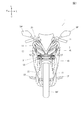
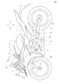
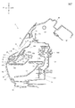
図1,図2に示す鞍乗り型車両1は、車体フレーム10の前端に設けられたヘッドパイプ11に、フロントカウルステイ80(図6参照)を介してヘッドライト装置2が設けられている。なお、ヘッドパイプ11には操舵装置20が左右に回動可能に支持されている。
In the saddle-ride type vehicle 1 shown in FIGS. 1 and 2, a
図2に示すように、車体フレーム10は、ヘッドパイプ11から後方に延びるメインフレーム12を有しており、このメインフレーム12にエンジンEが固定されている。
メインフレーム12の後部に、ピボット12pでスイングアーム13が揺動可能に設けられ、このスイングアーム13の後端に、エンジンEで駆動される後輪WRが支持されている。
As shown in FIG. 2, the
A
操舵装置20は、ハンドル21で回動操作される一対のフロントフォーク22を有しており、このフロントフォーク22の下端に前輪WFが支持されている。
操舵装置20の後方に燃料タンクTが配置され、その後方に、運転者が座るシートSが配置されている。メインフレーム12の後部下部には運転者が足を載せるステップSTが設けられている。
The
A fuel tank T is disposed behind the
この鞍乗り型車両のヘッドライト装置2は、ヘッドライトHLと、フロントカウル30とを備えている。
図7に示すように、ヘッドライトHLは、光源101とリフレクタ102とが設けられたハウジング70と、このハウジング70の前面を覆うレンズ60とを有している。
The
As shown in FIG. 7, the headlight HL includes a
図3に示すように、フロントカウル30は、レンズ60の周囲61,62(図4)を覆い、レンズ60の照射面63を前方に臨ませるためのライト開口部34を有している。ライト開口部34の近くには、走行風をヘッドライト後方へ取り入れるエア取り入れ口35が設けられている。
As shown in FIG. 3, the
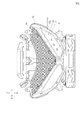
図4,図7に示すように、レンズ60の前面側には、ライト開口部34とエア取り入れ口35との間を仕切る仕切壁67が設けられ、該仕切壁67の先端67cからエア取り入れ口35側のレンズ60の前面が黒く塗装されている。断面視での塗装部68を図7に仮想線(68)で示す。また、正面視での塗装部68を、図5にクロスハッチ(68)で示す。
一方、図3,図7に示すように、フロントカウル30には、レンズ60の前面に向かって(後方へ向かって)仕切壁67の少なくとも片面に沿う対向壁36が設けられている。
As shown in FIGS. 4 and 7, a
On the other hand, as shown in FIGS. 3 and 7, the
この鞍乗り型車両のヘッドライト装置2によれば、フロントカウル30のライト開口部34近くに設けられたエア取り入れ口35によって、図7に矢印Aで示すように走行風をヘッドライト後方へ取り入れることができる。
According to the
そして、レンズ60の前面側に、ライト開口部34とエア取り入れ口35との間を仕切る仕切壁67が設けられ、該仕切壁67の先端67cからエア取り入れ口35側のレンズ60の前面(68)が黒く塗装され、さらに、フロントカウル30には、レンズ60の前面に向かって仕切壁67の少なくとも片面に沿う対向壁36が設けられているので、ライト開口部34からエア取り入れ口35へ向かおうとする光があったとしても、その光はレンズ60に設けられた仕切壁67とカウル30に設けられた対向壁36とで阻まれやすくなる。
A
また、ハウジング内光源101からレンズ60を通じてエア取り入れ口35へ向かおうとするする光は、仕切壁67の先端67cからエア取り入れ口35側のレンズ60の前面に施された黒色の塗装面(68)によって阻止されることとなる。
Further, the light to be directed from the in-
したがって、この鞍乗り型車両のヘッドライト装置によれば、ライト開口部34近くにエア取り入れ口35が設けられているにもかかわらず、エア取り入れ口35からの光の漏れが防止(少なくとも著しく抑制)される。
エア取り入れ口35からの光の漏れが防止される結果として、車両の外観が向上し、商品性が向上する。
Therefore, according to the headlight device of the saddle-ride type vehicle, light leakage from the
As a result of preventing leakage of light from the
なお、図示の実施の形態では、フロントカウル30に設ける対向壁36は、仕切壁67の片面である下面に沿うように一つだけ設けたが、仕切壁67の両面(図7において上下面)に沿うように一対設けてもよい。そのように構成すると、ライト開口部34からエア取り入れ口35へ向かおうとする光をより確実に阻止する(遮光する)ことができる。
In the illustrated embodiment, only one opposing
図7に示すようにハウジング70は単一のヘッドライト用灯体(光源)101を備えていると共にレンズ60は複数の照射面63(図3,図4に示すようにこの実施の形態では吊り目状に左右2個)を備えている。
図3に示すように、車両前面視で、エア取り入れ口35は、複数の照射面63,63の間でかつ黒塗装部68(図5参照)と重なる位置に設けられている。
つまり、左右の吊り目状の照射面63,63の間に略逆三角形状に黒塗装部68が広がっており、この黒塗装部68の領域を活用してエア取り入れ口35が設けられている。
As shown in FIG. 7, the
As shown in FIG. 3, the
In other words, the
このように構成すると、レンズ60とハウジングを各1個にでき、かつ、複数の照射面63の間に、エア取り入れ口35を設けても光漏れが生じないため、エア取り入れ口35を複数の照射面63の間に設けることができ、結果として、ヘッドライト装置2全体の小型化が可能となる。
図7に示す光源101はLEDで構成されている。101bはそのLED用基板である。
If comprised in this way, since the
The
図7に示すように、ヘッドライトHLは、ポジションライトPL用の光源103およびその導光体104を有している。
車両前面視で(図7において矢印Rrの方向に見て)、ポジションライトPL用光源103は、レンズ60の照射面63から見て仕切壁67よりも遠く(後方)に配置され、導光体104は光源103と重なる位置104aから延びて、照射面63の仕切壁67に隣接する位置104bで照射面63に臨むように配置されている。
As shown in FIG. 7, the headlight HL includes a
When viewed from the front of the vehicle (as viewed in the direction of the arrow Rr in FIG. 7), the position light PL
このように構成すると、仕切壁67の先端67cからエア取り入れ口35側のレンズ60の前面に亘って施された黒色塗装部68の背部のレンズ60内空間60sを有効に利用して、ポジションライトPL用の光源103および導光体104の配置の自由度を高めることができる。
With this configuration, the position light is effectively utilized by using the
なお、この実施の形態では、レンズ60の照射面63はその一部(上部)としてポジションライトPL用の照射面63pを有しており、導光体104は光源103と重なる位置104aから、ポジションライトPL用の照射面63pの内側面と対向する位置(104b)まで延びている。
光源103はLEDで構成されている。103bはそのLED用基板である。105はリフレクタ、106はリフレクタ105の支持部材である。
In this embodiment, the
The
図7に示すように照射面63を形成するレンズ壁63wは、仕切壁67に対し、該仕切壁67の起立方向(車体前後方向)に関して中間部67bに接続されている。
このように構成すると、照射面63を形成するレンズ壁63wが黒色塗装部68の中間(67b)に向けて接続されることとなるので、光漏れがより生じ難くなる。
As shown in FIG. 7, the
If comprised in this way, since the
レンズ60の前面側には、照射面63と仕切壁67との間において車両後方に向かって凹む凹溝69が形成され、この凹溝69に、フロントカウル30の対向壁36が入り込んでいる。
このように構成すると、仕切壁67と凹溝69と対向壁36とでラビリンス形状が構成されるため、光漏れがさらに生じ難くなる。
On the front side of the
If comprised in this way, since the labyrinth shape is comprised by the
図7において、107はリフレクタ102の支持部材、108は光軸調整用のアジャスタ、109はそのためのボールジョイントである。
In FIG. 7, 107 is a support member for the
図1〜図3において、40は操舵装置20の左右を覆うミドルカウルである。90はヘッドライトHLの前側下方にライセンスプレート(図示せず)を支持するプレート部91を有するライセンスプレートステイ90であり、その左右の支持アーム93の後端94が、図6に示すように、ヘッドライトハウジング70の下面71に設けられたステイ支持部72によって支持されている。
1 to 3,
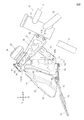
図4,図6に示すように、フロントカウルステイ80は、ヘッドパイプ11から前方に延びており、ヘッドライトHLの左右上方73(L,R)と下部中央75とを固定している。
フロントカウルステイ80は、基部81bがヘッドパイプ11の取付部11bにボルトナット82で固定されるセンターアーム81と、このセンターアーム81から前方斜め下方に延びる下部アーム83と、センターアーム81の先端において左右に延びるパイプ状の横アーム84と、この横アーム84の両端に設けられたミラー固定部85、85と、このミラー固定部85よりも車幅方向内側において横アーム84の前部に垂下された、前記ヘッドライトハウジング70の上部左右73(L,R)の固定部86、86と、この左右の固定部86の後方において横アーム84の後部に設けられたメータM用固定部87,87とを有している。フロントカウルステイ80の上記各部は溶接によって一体的に構成することができる。
As shown in FIGS. 4 and 6, the front cowl stay 80 extends forward from the head pipe 11, and fixes the upper left and right 73 (L, R) of the headlight HL and the
The front cowl stay 80 includes a
下部アーム83の下端83bに前記ヘッドライトハウジング70の下部中央75がボルト(図示せず)で固定され、ミラー固定部85、85に左右のサイドミラーSM(図1、図2)がボルト(図示せず)で固定され、ヘッドライトハウジング70の上部左右73(L,R)の固定部86、86に該ヘッドライトハウジング70の上部左右73(L,R)がボルト(図示せず)で固定され、メータ用固定部87,87にメータMが固定される。
A
図3,図4に示すように、フロンカウル30は、中央下部31がレンズ60に設けた固定部64に固定され、左右上部がヘッドライトハウジング70の左右上部に設けられた固定部74(図4,図6)に固定されるとともにフロントカウルステイ80のミラー固定部85、85にサイドミラーSM(図1)と共に共締めにて固定され、吊り目状レンズ部63の周囲に設けられた係合部(係合凹(穴)部または係合凸(爪)部)65、66に対して、係合固定される。
As shown in FIGS. 3 and 4, the
以上、本発明の実施の形態について説明したが、本発明は上記の実施の形態に限定されるものではなく、本発明の要旨の範囲内において適宜変形実施可能である。 Although the embodiments of the present invention have been described above, the present invention is not limited to the above-described embodiments, and can be appropriately modified within the scope of the gist of the present invention.
1:鞍乗型車両、2:ヘッドライト装置、30:フロントカウル、34:ライト開口部、35:エア取り入れ口、36:対向壁、60:レンズ、61,62:レンズの周囲、63:照射面63、63w:レンズ壁、67:仕切壁、67b:中間部、67c:仕切壁の先端、68:黒塗装部、69:凹溝、70:ハウジング、101:光源(ヘッドライト用灯体)、102:リフレクタ、103:ポジションライト用光源、104:の導光体、HL:ヘッドライト、PL:ポジションライト。
1: straddle-type vehicle, 2: headlight device, 30: front cowl, 34: light opening, 35: air intake port, 36: facing wall, 60: lens, 61, 62: lens periphery, 63:
Claims (5)
前記レンズ(60)の周囲(61,62)を覆い、レンズ(60)の照射面(63)を前方に臨ませるためのライト開口部(34)を有するフロントカウル(30)とを備えた鞍乗り型車両のヘッドライト装置において、
前記フロントカウル(30)の、ライト開口部(34)近くに、走行風をヘッドライト後方へ取り入れるエア取り入れ口(35)が設けられているとともに、
前記レンズ(60)の前面側に、前記ライト開口部(34)とエア取り入れ口(35)との間を仕切る仕切壁(67)が設けられ、該仕切壁(67)の先端(67c)から前記エア取り入れ口(35)側のレンズ(60)の前面が黒く塗装(68)され、
前記フロントカウル(30)には、前記レンズ(60)の前面に向かって前記仕切壁(67)の少なくとも片面に沿う対向壁(36)が設けられていることを特徴とする鞍乗り型車両のヘッドライト装置。 A headlight (HL) having a housing (70) provided with a light source (101) and a reflector (102), and a lens (60) covering the front surface of the housing (70);
A front cowl (30) having a light opening (34) for covering the periphery (61, 62) of the lens (60) and facing the irradiation surface (63) of the lens (60) forward. In the headlight device of a riding type vehicle,
The front cowl (30) is provided near the light opening (34) with an air intake (35) for taking the running wind behind the headlight,
A partition wall (67) for partitioning the light opening (34) and the air intake port (35) is provided on the front side of the lens (60), and from the tip (67c) of the partition wall (67). The front surface of the lens (60) on the air intake (35) side is painted black (68),
The front cowl (30) is provided with a facing wall (36) along at least one side of the partition wall (67) toward the front surface of the lens (60). Headlight device.
前記ハウジング(70)は単一のヘッドライト用灯体(101)を備えていると共に前記レンズ(60)は複数の照射面(63)を備え、
車両前面視で、前記エア取り入れ口(35)は、前記複数の照射面(63)の間でかつ前記黒塗装部(68)と重なる位置に設けられていることを特徴とする鞍乗り型車両のヘッドライト装置。 In claim 1,
The housing (70) includes a single headlight lamp (101) and the lens (60) includes a plurality of irradiation surfaces (63).
The saddle-ride type vehicle characterized in that the air intake (35) is provided between the plurality of irradiation surfaces (63) and overlaps the black paint portion (68) when viewed from the front of the vehicle. Headlight device.
前記ヘッドライト(HL)は、ポジションライト(PL)用の光源(103)およびその導光体(104)を有しており、
車両前面視で、ポジションライト(PL)用光源(103)は、前記レンズ(60)の照射面(63)から見て前記仕切壁(67)よりも遠くに配置され、導光体(104)は光源(103)と重なる位置(104a)から延びて、前記照射面(63)の前記仕切壁(67)に隣接する位置(104b)で照射面(63)に臨むように配置されていることを特徴とする鞍乗り型車両のヘッドライト装置。 In claim 1 or 2,
The headlight (HL) has a light source (103) for position light (PL) and a light guide body (104) thereof,
When viewed from the front of the vehicle, the light source (103) for position light (PL) is disposed farther than the partition wall (67) when viewed from the irradiation surface (63) of the lens (60), and is a light guide (104). Is arranged so as to extend from a position (104a) overlapping the light source (103) and to face the irradiation surface (63) at a position (104b) adjacent to the partition wall (67) of the irradiation surface (63). A headlight device for a saddle-ride type vehicle.
前記照射面(63)を形成するレンズ壁(63w)は、前記仕切壁(67)に対し、該仕切壁(67)の起立方向に関して中間部(67b)に接続されることを特徴とする鞍乗り型車両のヘッドライト装置。 In any one of Claims 1-3,
The lens wall (63w) forming the irradiation surface (63) is connected to the intermediate portion (67b) with respect to the rising direction of the partition wall (67) with respect to the partition wall (67). Headlight device for riding type vehicles.
前記レンズ(60)の前面側には、前記照射面(63)と前記仕切壁(67)との間において車両後方に向かって凹む凹溝(69)が形成され、この凹溝(69)に、前記フロントカウル(30)の対向壁(36)が入り込んでいることを特徴とする鞍乗り型車両のヘッドライト装置。 In any one of Claims 1-4,
On the front side of the lens (60), a concave groove (69) is formed that is recessed toward the rear of the vehicle between the irradiation surface (63) and the partition wall (67). A headlight device for a saddle-ride type vehicle, wherein an opposing wall (36) of the front cowl (30) is inserted.
Priority Applications (2)
| Application Number | Priority Date | Filing Date | Title |
|---|---|---|---|
| JP2015247041A JP6238951B2 (en) | 2015-12-18 | 2015-12-18 | Headlight device for saddle-ride type vehicles |
| PH12016000463A PH12016000463A1 (en) | 2015-12-18 | 2016-12-12 | Headlight apparatus of saddle-type vehicle |
Applications Claiming Priority (1)
| Application Number | Priority Date | Filing Date | Title |
|---|---|---|---|
| JP2015247041A JP6238951B2 (en) | 2015-12-18 | 2015-12-18 | Headlight device for saddle-ride type vehicles |
Publications (2)
| Publication Number | Publication Date |
|---|---|
| JP2017109672A true JP2017109672A (en) | 2017-06-22 |
| JP6238951B2 JP6238951B2 (en) | 2017-11-29 |
Family
ID=59081649
Family Applications (1)
| Application Number | Title | Priority Date | Filing Date |
|---|---|---|---|
| JP2015247041A Active JP6238951B2 (en) | 2015-12-18 | 2015-12-18 | Headlight device for saddle-ride type vehicles |
Country Status (2)
| Country | Link |
|---|---|
| JP (1) | JP6238951B2 (en) |
| PH (1) | PH12016000463A1 (en) |
Cited By (2)
| Publication number | Priority date | Publication date | Assignee | Title |
|---|---|---|---|---|
| JP2017202713A (en) * | 2016-05-10 | 2017-11-16 | 川崎重工業株式会社 | Head lamp device for saddle-riding type vehicle |
| WO2019064797A1 (en) * | 2017-09-29 | 2019-04-04 | 本田技研工業株式会社 | Combination light |
Citations (5)
| Publication number | Priority date | Publication date | Assignee | Title |
|---|---|---|---|---|
| JPH0353364Y2 (en) * | 1986-10-16 | 1991-11-21 | ||
| JP2001260965A (en) * | 2000-03-17 | 2001-09-26 | Honda Motor Co Ltd | Vehicle having transparent or semitransparent body cover |
| JP2010202129A (en) * | 2009-03-05 | 2010-09-16 | Stanley Electric Co Ltd | Light leakage preventing structure of motorcycle |
| JP2011111029A (en) * | 2009-11-26 | 2011-06-09 | Honda Motor Co Ltd | Front part lamp structure of saddle riding type vehicle |
| JP2013151178A (en) * | 2012-01-24 | 2013-08-08 | Yamaha Motor Co Ltd | Motorcycle |
-
2015
- 2015-12-18 JP JP2015247041A patent/JP6238951B2/en active Active
-
2016
- 2016-12-12 PH PH12016000463A patent/PH12016000463A1/en unknown
Patent Citations (5)
| Publication number | Priority date | Publication date | Assignee | Title |
|---|---|---|---|---|
| JPH0353364Y2 (en) * | 1986-10-16 | 1991-11-21 | ||
| JP2001260965A (en) * | 2000-03-17 | 2001-09-26 | Honda Motor Co Ltd | Vehicle having transparent or semitransparent body cover |
| JP2010202129A (en) * | 2009-03-05 | 2010-09-16 | Stanley Electric Co Ltd | Light leakage preventing structure of motorcycle |
| JP2011111029A (en) * | 2009-11-26 | 2011-06-09 | Honda Motor Co Ltd | Front part lamp structure of saddle riding type vehicle |
| JP2013151178A (en) * | 2012-01-24 | 2013-08-08 | Yamaha Motor Co Ltd | Motorcycle |
Cited By (2)
| Publication number | Priority date | Publication date | Assignee | Title |
|---|---|---|---|---|
| JP2017202713A (en) * | 2016-05-10 | 2017-11-16 | 川崎重工業株式会社 | Head lamp device for saddle-riding type vehicle |
| WO2019064797A1 (en) * | 2017-09-29 | 2019-04-04 | 本田技研工業株式会社 | Combination light |
Also Published As
| Publication number | Publication date |
|---|---|
| PH12016000463B1 (en) | 2018-06-25 |
| PH12016000463A1 (en) | 2018-06-25 |
| JP6238951B2 (en) | 2017-11-29 |
Similar Documents
| Publication | Publication Date | Title |
|---|---|---|
| EP2583884B1 (en) | Front structure of saddle-ride type vehicle | |
| JP6447383B2 (en) | Suction type vehicle intake structure | |
| US10391925B2 (en) | Vehicle headlight with a plurality of inner non spherical lenses transmitting light from a high beam and a low beam light source | |
| JP5048433B2 (en) | Winker integrated rearview mirror for saddle riding type vehicles | |
| JP7223607B2 (en) | Front structure of saddle type vehicle | |
| EP2835308B1 (en) | Front cowl stay attachment structure for saddle-ride type vehicle | |
| JP5211020B2 (en) | Front lighting structure of saddle-ride type vehicle | |
| JP2007186128A (en) | Motorcycle | |
| JP4762629B2 (en) | Motorcycle lamp unit | |
| WO2009122799A1 (en) | Vehicle body cover structure for straddle-riding type vehicle | |
| US8820987B2 (en) | Lighting device for mortorcycle | |
| JP2010132267A (en) | Handle cover of motorcycle | |
| JP2006076459A (en) | Vehicle | |
| JP2016005942A (en) | Saddle riding type vehicle | |
| JP6238951B2 (en) | Headlight device for saddle-ride type vehicles | |
| JP2015227102A (en) | Saddle-riding type vehicle | |
| JP6880212B2 (en) | Exterior parts structure of saddle-type vehicle | |
| WO2017018331A1 (en) | Saddled vehicle | |
| JP7141299B2 (en) | straddle-type vehicle | |
| JP6356627B2 (en) | A saddle-ride type vehicle equipped with a blinker | |
| JP5801236B2 (en) | Motorcycle lights | |
| JP6176859B2 (en) | Turn signal structure of vehicle | |
| JP7048758B2 (en) | License light for saddle-mounted vehicles | |
| JP5952144B2 (en) | Light fixture structure | |
| JP7096134B2 (en) | Saddle-type vehicle |
Legal Events
| Date | Code | Title | Description |
|---|---|---|---|
| A131 | Notification of reasons for refusal |
Free format text: JAPANESE INTERMEDIATE CODE: A131 Effective date: 20170718 |
|
| A521 | Request for written amendment filed |
Free format text: JAPANESE INTERMEDIATE CODE: A523 Effective date: 20170913 |
|
| TRDD | Decision of grant or rejection written | ||
| A01 | Written decision to grant a patent or to grant a registration (utility model) |
Free format text: JAPANESE INTERMEDIATE CODE: A01 Effective date: 20171024 |
|
| A61 | First payment of annual fees (during grant procedure) |
Free format text: JAPANESE INTERMEDIATE CODE: A61 Effective date: 20171031 |
|
| R150 | Certificate of patent or registration of utility model |
Ref document number: 6238951 Country of ref document: JP Free format text: JAPANESE INTERMEDIATE CODE: R150 |