JP2017109593A - Flight type inspection machine, and inspection system and inspection method using flight type inspection machine - Google Patents
Flight type inspection machine, and inspection system and inspection method using flight type inspection machine Download PDFInfo
- Publication number
- JP2017109593A JP2017109593A JP2015245134A JP2015245134A JP2017109593A JP 2017109593 A JP2017109593 A JP 2017109593A JP 2015245134 A JP2015245134 A JP 2015245134A JP 2015245134 A JP2015245134 A JP 2015245134A JP 2017109593 A JP2017109593 A JP 2017109593A
- Authority
- JP
- Japan
- Prior art keywords
- flight
- survey
- type research
- flight type
- aircraft
- Prior art date
- Legal status (The legal status is an assumption and is not a legal conclusion. Google has not performed a legal analysis and makes no representation as to the accuracy of the status listed.)
- Granted
Links
Images


Abstract
Description
本発明は、飛行型調査機、飛行型調査機を用いた調査システムおよび飛行型調査機を用いた調査方法に関し、詳しくは調査対象地点まで飛行して調査を実施する飛行型調査機、飛行型調査機を用いた調査システムおよび飛行型調査機を用いた調査方法に関する。 The present invention relates to a flight-type research machine, a research system using a flight-type research machine, and a research method using a flight-type research machine, and more specifically, a flight-type research machine that performs a survey by flying to a survey target point. The present invention relates to a survey system using a survey machine and a survey method using a flight type survey machine.
地震、火災、竜巻、洪水、津波等の災害が発生し構造物が損壊した場合、構造物内の負傷者の有無、危険物の状況の把握、建物、機器の損傷による危険の有無等の調査を安全かつ迅速に行う必要がある。しかし、構造物が損壊している場合には、通路が塞がっていたり、床面に様々なものが散乱していたりして進入を妨げられることが想定され、さらに人間が調査する場合には2次災害のリスクがある。2次災害のリスクを避けつつ対象を安全に調査するには、遠隔操作型のロボット等の利用が有効と考えられる。 When disasters such as earthquakes, fires, tornadoes, floods, and tsunamis occur, the structure is damaged, whether there are injuries in the structure, the status of dangerous goods, the presence of danger due to damage to buildings and equipment, etc. Need to be done safely and quickly. However, when the structure is damaged, it is assumed that the passage is blocked or that various things are scattered on the floor surface and the entry is hindered. There is a risk of the next disaster. In order to investigate the target safely while avoiding the risk of secondary disaster, it is considered effective to use a remote control type robot.
災害時に構造物内に進入し調査を行うロボットは、日本では阪神淡路大震災以降多数開発されており、瓦礫内に進入するための蛇型のものや、不整地走行に適したクローラ式のものが既に知られている。これらのロボットは、崩壊した建物の下部等の狭隘部への進入には有効であるが、大きな建物や高所等の調査では効率が悪いという欠点がある。 Numerous robots have been developed in Japan since the Great Hanshin-Awaji Earthquake to investigate structures that enter the structure during a disaster. There are snake-shaped robots for entering the rubble and crawler robots suitable for running on rough terrain. Already known. These robots are effective for entering narrow spaces such as the lower part of a collapsed building, but have the disadvantage that they are inefficient when investigating large buildings and high places.
この種の技術に関連して、特開2014−104797号公報には、床面を移動して建屋内に侵入するクローラ型の移動機構と、移動機構に設けられたカメラと、カメラのパンチルト機構と、移動機構に搭載可能な飛行体と、飛行体に設けられた発光体と、カメラが発光体を追尾するようにパンチルト機構を制御するパンチルト制御手段と、カメラで撮影された画像を表示する表示手段と、飛行体を操作する操作手段と、を備える建屋内調査システムが開示されている。 In relation to this type of technology, Japanese Patent Application Laid-Open No. 2014-104797 discloses a crawler-type moving mechanism that moves on the floor surface and enters the building, a camera provided in the moving mechanism, and a pan / tilt mechanism of the camera And a flying body that can be mounted on the moving mechanism, a light emitting body provided on the flying body, a pan / tilt control means for controlling the pan / tilt mechanism so that the camera tracks the light emitting body, and an image captured by the camera is displayed. An indoor survey system including a display unit and an operation unit for operating a flying object is disclosed.
しかし、特開2014−104797号公報に記載のシステムにおいて、飛行体の位置及び姿勢を地上または床面等から高い任意の点で保持したい場合(例えば、飛行体に搭載のカメラで定点観測したい場合)には、地上等を走行する移動体を任意の点で停止させる場合と異なり、その位置及び姿勢が保持されるように飛行体の制御を継続する必要がある。特に、飛行体がバッテリ駆動の場合には、継続飛行によりバッテリ電力が消費されるため、長時間の位置・姿勢保持が困難となる。 However, in the system described in Japanese Patent Application Laid-Open No. 2014-104797, when the position and posture of the flying object are desired to be held at a high point from the ground or floor surface (for example, when fixed point observation is desired with a camera mounted on the flying object) ), It is necessary to continue the control of the flying body so that the position and posture are maintained, unlike the case where the moving body traveling on the ground or the like is stopped at an arbitrary point. In particular, when the flying vehicle is battery-driven, battery power is consumed by continuous flight, so that it is difficult to maintain the position and posture for a long time.
本発明の目的は、2次災害のリスクを避け、安全、確実に、長時間にわたる調査が可能な飛行型調査機を提供することである。 An object of the present invention is to provide a flight type research machine capable of avoiding the risk of a secondary disaster and capable of conducting a survey for a long time safely and reliably.
本発明は上記の目的を達成するために、周囲の状況を調査する調査装置を搭載し、飛行装置により飛行する飛行型調査機において、前記飛行型調査機を任意の構造物に固定可能な固定装置と、を備えた、ことを特徴とする。 In order to achieve the above object, the present invention is equipped with a survey device for investigating the surrounding situation, and in a flight type survey aircraft that flies by a flight device, the flight type survey aircraft can be fixed to an arbitrary structure. And a device.
本発明によれば、2次災害のリスクを避け、安全、確実に、長時間にわたる調査が可能な飛行型調査機を提供することができる。 ADVANTAGE OF THE INVENTION According to this invention, the flight type investigation machine which can avoid the risk of a secondary disaster, and can investigate for a long time safely and reliably can be provided.
上記した以外の課題、構成及び効果は、以下の実施形態の説明により明らかにされる。 Problems, configurations, and effects other than those described above will be clarified by the following description of embodiments.
以下、図面を用いて、本発明の実施形態に係る飛行型調査機および飛行型調査機を用いた調査システムについて詳細に説明する。 Hereinafter, a flight type research machine and a research system using the flight type research machine according to an embodiment of the present invention will be described in detail with reference to the drawings.
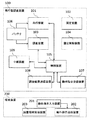
図1は、本発明の実施形態に係る飛行型調査機を用いた調査システムの構成を示すブロック図である。 FIG. 1 is a block diagram showing a configuration of an investigation system using a flight type investigation machine according to an embodiment of the present invention.
本実施形態の飛行型調査機を用いた調査システムは、飛行型調査機100と端末装置200とを有して構成される。
The survey system using the flight type research machine of the present embodiment includes the flight
飛行型調査機100は、バッテリ106と、バッテリ106を電源として動作する飛行装置101と、飛行装置101によって飛行した後、任意の構造物の被固定箇所に固定可能な固定装置102と、固定装置102によって被固定箇所に固定した状態を解除する固定解除装置104と、バッテリ106を電源として動作し、少なくとも固定装置によって被固定箇所に固定した状態で、周囲の調査を行う調査装置103と、少なくとも飛行装置101および調査装置103の制御を行う制御装置105と、を備えている。飛行装置101および調査装置103以外の構成も、バッテリ106を電源として動作するものであってもよい。制御装置105は、飛行装置101および調査装置103以外の構成も制御するものであってもよい。
The flight
固定装置102によって被固定箇所に固定した状態で調査装置103による調査を実行することで、被固定箇所に固定した状態では飛行装置101を停止することができるので飛行装置101によるバッテリ106の消費を低減することができ、その分、調査装置103を駆動する電源を確保することができ、長時間の調査を実行可能となる。
By performing the investigation by the
飛行型調査機100は、飛行型調査機100に対する動作指示を受信する動作指示受信装置107と、調査装置103による調査結果を送信する調査結果送信装置108と、をさらに備える場合があり、この場合、制御装置105は、前記動作指示受信装置によって受信した動作指示に基づき、前記飛行装置および前記調査装置の制御を行う。
The flight
端末装置200は、操作者による飛行型調査機100に対する動作指示の入力を受け付ける動作指示入力装置201と、動作指示入力装置201で受け付けた動作指示を送信する動作指示送信装置202と、調査結果を受信する調査結果受信装置203と、を有する。飛行型調査機100に対する動作指示は、動作指示入力装置201で入力を受け付け、動作指示送信装置202から送信される。端末装置200の調査結果受信装置203は、飛行型調査機100の調査結果送信装置108によって送信された調査結果を受信する。この動作指示や調査結果の送受は、有線通信で行ってもよいが、無線通信で行うことが好ましく、電波通信、赤外線通信など既知の如何なる通信方式を用いてもよい。このように構成することで、端末装置200による飛行型調査機100の遠隔操作が可能となる。
The
本実施形態の飛行型調査機を用いた調査システムでは、飛行型調査機100を複数設けてもよい。この場合、一の飛行型調査機100は、この一の飛行型調査機100とは別の他の飛行型調査機100に対する動作指示を端末装置200あるいはさらに別の飛行型調査機100から受信し、該動作指示を該他の飛行型調査機100に対して送信するとともに、該他の飛行型調査機100からの調査結果を受信し、該調査結果を端末装置200あるいはさらに別の飛行型調査機100に対して送信する中継装置109をさらに備えている。なお、中継のみを行う飛行型調査機100には、調査装置103や調査結果送信装置108を設けなくてもよい場合がある。
In the research system using the flight type research machine of the present embodiment, a plurality of flight
飛行装置101は、2重反転式プロペラによって飛行を行う装置である場合がある。飛行装置101は、他の如何なる機構によって飛行するものであってもよい。
The
固定装置102は磁石である場合があり、この場合、強磁性体の箇所(鉄製の柱、壁、梁、天井、天井クレーン、その他の重機など)である被固定箇所に磁石である固定装置102を吸着させ、飛行型調査機100を固定装置102によって被固定箇所に固定する。この磁石である固定装置102は、電磁石であってもよいし、永久磁石であってもよい。固定装置102が電磁石である場合には、固定装置102は、制御装置105によって制御されて電磁石が励磁され、強磁性体の箇所である被固定箇所に固定するものであってもよいし、固定解除装置104は、制御装置105によって制御されて電磁石が消磁され、被固定箇所への固定を解除するものであってもよい。固定装置102が永久磁石である場合には、簡易な構成で強磁性体の箇所である被固定箇所への固定が実現できる。固定解除装置104は、固定装置102と被固定箇所との間を離間させることによって固定を解除するものであってもよい。例えば、固定解除装置104は、飛行型調査機100から被固定箇所に向けて突出させるように移動制御可能な棒状部材を設け、制御装置105がこの棒状部材を被固定箇所に向けて突出させることで、固定装置102と被固定箇所との間を、磁石である固定装置102の吸着力が及ばない距離まで離間させ、被固定箇所への固定を解除するものであってもよい。
The
固定装置102は鉤部である場合がある。この場合、被固定箇所は、例えば天井クレーンのフックや露出した配管などの、鉤部である固定装置102を引っ掛けることが可能な個所である。
The
固定装置102としては、このほか、飛行装置101の重量に耐えられる程度の強度で、粘着面で被固定箇所に固定するものであってもよいし、両面テープ、ガムテープ、瞬間接着剤などを用いてもよいが、再利用可能な手段で固定するものであることが望ましい。
In addition, the fixing
また、飛行型調査機100における固定装置102を設ける位置、すなわち飛行型調査機100のうち被固定箇所と接触する位置は、飛行型調査機100の上面であってもよいし、側面、底面などいずれの位置であってもよい。後述の実施例1のように、飛行型調査機100が外殻11に覆われた飛行体10である場合には、外殻11の頭頂部に固定装置102としての固定装置22を設けてもよいし(図3参照)、これ以外にも、外殻11の球形を地球に見立てた場合の、赤道位置よりも上部(北半球)のいずれかの表面に固定装置22を設けてもよいし、赤道位置のいずれかの表面に固定装置22を設けてもよいし、赤道位置よりも下部(南半球)のいずれかの表面に固定装置22を設けてもよい。
Further, the position at which the
調査装置103は、周囲の映像を撮影する撮影装置を含む場合がある。この撮影装置で撮影した映像は、調査結果として端末装置200に送信され、端末装置200では表示装置(不図示)でこの映像を表示することが可能である。また、調査装置103は、飛行型調査機100の周囲の温度を測定する温度測定装置を含んでもよいし、飛行型調査機100の周囲のガス成分を測定するガス測定装置を含んでもよいし、飛行型調査機100の周囲の音を収録する音収録装置を含んでもよいし、飛行型調査機100の周囲の放射線線量を測定する放射線測定装置を含んでもよいし、その他、既知のあらゆる環境調査を行う装置を含んでもよい。
The
飛行型調査機100を複数設けた場合、一の飛行型調査機100の撮影装置が、この一の飛行型調査機100とは別の他の飛行型調査機100を撮影し、操作者は一の飛行型調査機100の撮影装置で撮影した他の飛行型調査機100の映像を見ながら、端末装置200を操作して他の飛行型調査機100を操縦することができる。
When a plurality of flight-
ところで、特開2014−104797号公報のクローラ型の移動機構のように、地表面又は床面等の上を移動するタイプの遠隔操作ロボットによる追尾映像に基づく飛行体の操作は、当該遠隔操作ロボットの移動範囲により制限されるため、結果的に走行体による調査範囲が限定されるという課題がある。例えば、クローラによる乗り越えが不可能な障害物が地上等に存在する場合、当該障害物を越えた領域の飛行体の追尾は困難となり、飛行体による調査も困難となる。また、床面上を移動する移動機構に搭載したカメラは床面近傍に設定されているため、当該移動機構より上方に障害物が存在する場合には、高い位置を飛ぶ飛行体を当該障害物の影響で追尾しにくくなり、飛行体による調査が困難となる。また、移動機構から出力される無線で飛行体を制御する場合に電波を反射する素材の構造物が存在すると、当該構造物が飛行体への信号到達の障害となり、所望の場所へ飛行体を移動できない虞もある。 Incidentally, like a crawler type moving mechanism disclosed in Japanese Patent Application Laid-Open No. 2014-104797, an operation of a flying object based on a tracking image by a remote operation robot of a type moving on the ground surface or a floor surface is performed by the remote operation robot. As a result, there is a problem that the investigation range by the traveling body is limited. For example, when there is an obstacle on the ground or the like that cannot be overtaken by the crawler, it is difficult to track the flying object in the area beyond the obstacle, and the investigation by the flying object is also difficult. In addition, since the camera mounted on the moving mechanism that moves on the floor surface is set near the floor surface, if there is an obstacle above the moving mechanism, the flying object flying at a high position should be This makes tracking difficult and makes it difficult to investigate with flying objects. In addition, when a flying object is controlled by radio output from a moving mechanism, if there is a structure made of a material that reflects radio waves, the structure becomes an obstacle to reaching the signal to the flying object, and the flying object is moved to a desired location. There is a possibility that it cannot move.
本実施形態によれば、操作者は一の飛行型調査機100の撮影装置で撮影した他の飛行型調査機100の映像を見ながら、端末装置200を操作して他の飛行型調査機100を操縦することができ、一の飛行型調査機100は、飛行装置101によって飛行するため移動範囲を広めることができ、さらに複数の中継用の飛行型調査機100を用いることで障害物を越えてさらに奥の調査を行うことができる。
According to the present embodiment, the operator operates the
以下、本発明による飛行型調査機を用いた調査システムの実施例について図面を用いて詳細に説明する。 Embodiments of a survey system using a flight type survey machine according to the present invention will be described below in detail with reference to the drawings.
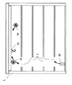
図2は、本発明に係る飛行型調査機を用いた調査システムの実施例としての災害時調査システムによって、建屋内を調査している状況を示した説明図である。 FIG. 2 is an explanatory diagram showing a situation in which a building is being surveyed by a disaster survey system as an embodiment of a survey system using a flight type research machine according to the present invention.
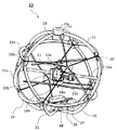
図3は、本発明に係る飛行型調査機の実施例としての飛行体の概略構成を示す斜視図である。 FIG. 3 is a perspective view showing a schematic configuration of a flying object as an embodiment of the flight type research aircraft according to the present invention.
図4は、本発明に係る飛行型調査機の実施例としての飛行体の制御系を示すブロック図である。 FIG. 4 is a block diagram showing the control system of the flying object as an embodiment of the flight type research aircraft according to the present invention.
本発明による飛行型調査機を用いた調査システムは、災害時の建屋内の調査に特化せずに、災害時以外の建屋、人口建造物内の調査や、洞窟、地下、山岳地帯などの調査などにも適用可能なものであるが、この実施例では、本発明に係る飛行型調査機を用いた調査システムの実施例としての災害時調査システムについて説明する。 The survey system using the flight type surveying machine according to the present invention is not specialized in surveying buildings in a disaster, surveys in buildings and artificial buildings other than disasters, caves, underground, mountainous areas, etc. In this embodiment, a disaster investigation system as an embodiment of the investigation system using the flight type research machine according to the present invention will be described.
まず、図2を用いて本実施例の災害時調査システムの構成について説明する。 First, the configuration of the disaster investigation system of this embodiment will be described with reference to FIG.
災害時調査システムは、調査対象である建屋1内のオペレータ(操作者)が直接目視で確認可能な場所に固定する飛行型調査機100としての飛行体10(第一の飛行型調査機)と、飛行体10を無線の中継局としてオペレータからは直接確認できない場所に侵入して調査を行う第二の飛行体30(例えば飛行体10と同じ構成、第二の飛行型調査機)と、オペレータが飛行体10、第二の飛行体30を操作するための端末装置200としての遠隔制御装置40と、から構成されている。図2の例では、飛行体10は、建屋1内の各フロアの開口部2を通過して天井クレーン50に、固定装置102としての固定装置22(図3、図4参照)により固定された状態を示している。
The disaster investigation system includes a flying object 10 (first flight type investigation machine) as a flight
図2では、端末装置200としての遠隔制御装置40を建屋1内に示したが、建屋1に崩落の可能性がある場合等は、飛行体10と通信するためのアンテナ(例えば、動作指示送信装置202および調査結果受信装置203を構成するアンテナ)と、例えば雲台付きのカメラ(例えば、飛行体10の周囲を撮影し、建屋1の外でこの撮影映像を見ながら飛行体10の操縦を行うためのTVカメラ)のみを、図2に示した遠隔制御装置40の位置に設置し、オペレータは建屋1の外から(例えば、動作指示入力装置201により)操作してもよい。さらに、他のフロアの開口部2付近の構造物に飛行体10を固定し、そのフロアを第二の飛行体30で調査可能なことは容易にわかる。
In FIG. 2, the
次に、飛行体10の構成について図3、図4を用いて説明する。
Next, the configuration of the flying
飛行体10は球形の外殻11の中央部分にシャフト12aが取り付けられており、シャフト12aの中央部分に、飛行装置101としての2重反転式プロペラ13を保持した構成となっている。2重反転式プロペラ13は上プロペラ13aと下プロペラ13bとを有し、これらを逆回転させることで反トルクを相殺し安定した飛行を実現する。
The flying
また、飛行体10には、2重反転式プロペラ13をシャフト12aの軸回り(ピッチ軸回り)に回動させるプロペラ方向制御装置14aと、2重反転式プロペラ13をシャフト12bの軸回り(ロール軸回り)に回動させるプロペラ方向制御装置14bと、を備えている。シャフト12aの軸方向とシャフト12bの軸方向とは直交している。
Further, the flying
飛行体10の下部には、飛行体各部に電源を供給するためのバッテリ15と電源回路16(図4参照)(バッテリ106に相当)が備えられており、さらにパンチルトを調整可能な雲台17(図4参照)に搭載されたカメラ18が備えられている。カメラ18は、動画、静止画、暗視画像、暗視映像など各種撮影をすることができるものであってもよい。
A
外殻11は、球形の外周形状を成すように湾曲した複数枚(本実施例では30枚)の例えば樹脂製の外殻片11aを有し、その各外殻片11aの一端を接続部品11b(例えば樹脂製)に接続し他端を別の接続部品11bに接続して球形を形成して成る。この外殻11の内部に2重反転式プロペラ13やカメラ18等の構成を収容することにより、飛行体10の飛行時に構造物の外壁等に衝突したり、地面に落下したりした場合に内部に擁した構成を衝撃から保護することができる。また、本実施例の外殻11の構成によれば、外殻11の内部が視認可能であり、2重反転式プロペラ13の動作等を目視することができる。また、本実施例の外殻11の構成によれば、外殻11を軽量化することができ、2重反転式プロペラ13の負荷を軽減することができる。
The
外殻11には、カメラ18で撮影する際の照明のための複数の白色LED19、およびオペレータに例えば飛行体10の進行方向を示すためのカラーLED20が備えられている。
The
例えば、図2の例で言えば、カラーLED20を点灯することで飛行体10、30の位置を認識可能とすることができる。飛行体30のカラーLED20の灯りを飛行体10のカメラ18で追尾して(飛行体10の雲台17をパンチルト制御して)、オペレータはこの飛行体10のカメラ18の撮影映像を見ながら飛行体30の操縦を行うことができる。
For example, in the example of FIG. 2, the position of the flying objects 10 and 30 can be recognized by turning on the
また、飛行体10の外殻11が球形であるが故に飛行体10の前後左右が不明であり、飛行体10を操縦する際の進行方向を確認することが困難であるが、カラーLED20を外殻11の例えば前方に設けることで飛行体10の前後左右が明確になる。すなわち、遠隔制御装置40で飛行体10が前方に進むように操縦すれば、カラーLED20を前方にした方向に飛行体10が進むことがあらかじめ分かっているので、飛行体10を操縦しやすくすることができる。
Further, since the
さらに、飛行体10には、飛行時の姿勢を検出する姿勢検出装置(例えばジャイロ)21が備えられている。さらに、飛行体10の上部には、調査対象の近傍の被固定箇所に飛行体10を固定するための固定装置22とともに、固定装置22の固定を解除するための固定解除装置104としての固定解除装置23が備えられている。さらに、飛行体10には、第二の飛行体30の制御信号(動作指示に相当)を中継する無線中継機24(図4参照)(中継装置109に相当)と、第二の飛行体30のカメラ18の映像信号(調査結果に相当)を中継する映像中継機25(図4)(中継装置109に相当)も具備されている。
Further, the flying
建屋1内の狭隘な場所の通過では、飛行体10は構造物に接触することが想定されるが、図3に示すように、2重反転式プロペラ13の周りを球形の外殻11が囲っている構造であるため、2重反転式プロペラ13が構造物に接触しにくい構造となっている。
When passing through a narrow place in the
さらに、飛行体10の下部にバッテリ15等の重量物を配置することで、飛行体10が予期せぬ着地をした場合にも、飛行体10の重心位置によるモーメントのためバッテリが接地面近傍にきて2重反転式プロペラ13がほぼ鉛直方向を向くため、2重反転式プロペラ13を駆動することで再飛行可能な構成となっている。
Further, by placing a heavy object such as a
さらに、飛行体10を固定装置22で調査対象近傍の構造物(被固定箇所)に固定することで、固定後はホバリングをする必要がなくなるため、バッテリ15の消費が抑制され、雲台17を用いたカメラ18による調査を長時間行うことができる。
Furthermore, by fixing the flying
遠隔制御装置40は、動作指示入力装置201としての操作入力装置41、43を備える。例えば、操作入力装置41は飛行体10に対する入力を行う装置であり、操作入力装置43は第二の飛行体30に対する入力を行う装置である。操作入力装置41、43は共通の装置にしてもよい。飛行体の数をより多く用いる場合には操作入力装置の数をそれに応じて増やしてもよい。
The
遠隔制御装置40は、動作指示送信装置202としての無線送信機42、44を備える。例えば、無線送信機42は飛行体10に向けた送信を行う装置であり、無線送信機44は第二の飛行体30に向けた送信を行う装置である。無線送信機42、44は共通の装置にしてもよい。飛行体の数をより多く用いる場合には無線送信機の数をそれに応じて増やしてもよい。
The
遠隔制御装置40は、調査結果受信装置203としての映像受信機46を備え、調査結果受信装置203で受信した映像を表示する表示装置としてのモニタ45を備える。
The
飛行体10は、制御装置105としてのマイコン27を備えている。マイコン27は、調査装置103としてのカメラ18や雲台17の動作制御を行うことができる。雲台17を動作させることでカメラ18が撮影する向きを変えることができる。
The flying
2重反転式プロペラ13の回転制御は、マイコン27によって制御されたスピードコントローラ27cが、2つのプロペラうちの上のプロペラを回すプロペラ上モータ27eや2つのプロペラのうちの下のプロペラを回すプロペラ下モータ27fを駆動することで実施される。
The rotation control of the double reversing
2重反転式プロペラ13の傾き制御(向き制御)は、マイコン27によって制御されたスピードコントローラ27dが、プロペラ方向制御装置14a、14bを駆動するプロペラ方向制御(ロール)27gやプロペラ方向制御(ピッチ)27hを駆動することで実施される。
Tilt control (orientation control) of the double reversing
飛行体10は、カメラ18のほかに、さらにカメラ18aを備え、カメラ18とは異なる映像を撮影することができるようにしてもよい。
The flying
マイコン27は、固定解除装置23の動作制御を行うことができる。
The
第二の飛行体30は、飛行体10と同じ構成にすることができる。また、第二の飛行体30は、調査装置103としての環境計測センサ28を備えてもよい。環境計測センサ28は環境データ(温度、放射線線量等)を取得し、その環境データを調査結果として調査結果送信装置108(図4では対応する構成の図示省略)によって送信する。飛行体10も環境計測センサ28を備えてもよいことはもちろんである。
The
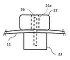
次に、固定装置22、固定解除装置23の一例について図5A,Bを用いて説明する。図5Aは、固定装置22の近傍の断面図であり、固定解除装置23の動作前を示す図である。図5Bは、固定装置22の近傍の断面図であり、固定解除装置23の動作時を示す図である。
Next, an example of the fixing
本実施例では、固定装置22としてドーナツ状の永久磁石を用いている。固定装置22として磁石を用いれば、鉄製の構造物たとえば天井クレーンや天井空調機等に飛行体10を磁力で吸着し固定することが可能となる。
In this embodiment, a donut-shaped permanent magnet is used as the fixing
本実施例では、固定解除装置23としてソレノイドを用いている。ソレノイドに通電することでピン26(棒状部材)をドーナツ状の磁石の中心の穴22aから磁石(固定装置22)が吸着している鉄製の構造物(被固定箇所)に対して押しつけて固定装置22と被固定箇所との間を離間させることが可能であり、このピン26を被固定箇所に押しつける力を磁石の吸着力から飛行体の重量を引いた力より強くすることで固定解除装置23による固定の解除を実現できる。
In this embodiment, a solenoid is used as the fixing
さらに、図2に示したような位置に飛行体10を固定した場合は、固定解除装置23として飛行体10の下部にロープ(不図示)を結んでおき、解除の場合はロープを引っ張ることでも固定を解除することができる。この場合、ロープを電源ケーブルにしてバッテリの代わりに電源を供給すれば、バッテリの心配なく飛行体10の雲台付きカメラ18を使用することができる場合がある。
Further, when the flying
図6は、飛行体10の上部に、固定装置22としての鉤部であるフック状部材22bを取り付けた例を示す斜視図である。
FIG. 6 is a perspective view showing an example in which a hook-
このような固定装置22の場合は、水平に設置された配管や天井クレーンのフック等にフック状部材22bを引っ掛けることで飛行体10を固定することができる。この場合の解除は、2重反転式プロペラ13を駆動して再度飛行し、横方向に移動して配管からフック状部材22bを外すことで実現でき、この制御が固定解除装置104に相当する。
In the case of such a
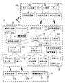
次に、本実施例の災害時調査システムを用いて建屋内の調査を行う手順について図7を用いて説明する。図7は、本実施例の災害時調査システムによって建屋内を調査するときの流れを示したフローチャートである。 Next, the procedure for conducting a survey in a building using the disaster survey system of this embodiment will be described with reference to FIG. FIG. 7 is a flowchart showing a flow when the building is surveyed by the disaster survey system of this embodiment.
オペレータは、遠隔制御装置40で飛行体10を直接目視または目視と飛行体10搭載のカメラ映像を見ながら操縦し、調査対象フロアに固定装置22を使って飛行体10を固定する。次に、飛行体10に搭載した雲台17を操作し、飛行体10を固定した周囲の映像をカメラ18により取得し、建物の損傷、障害物の状況等の調査を行う(ステップS110、S111)。
The operator controls the flying
飛行体10の周辺に建物等の損傷がなく、調査対象フロアのさらに奥まで調査可能である場合は第二の飛行体30を飛行させて調査を行う。さらに、第二の飛行体30に搭載した環境計測センサ28により環境データ(温度、放射線線量等)も取得する(ステップS112、S113)。このとき、オペレータは第二の飛行体30用の操作入力装置43を操作し、制御信号は飛行体10の無線中継機24を経由して第二の飛行体30に送られる。第二の飛行体30のカメラ18の映像は飛行体10の映像中継機25を経由して遠隔制御装置40のモニタ45に表示される。
When there is no damage to the building or the like around the flying
オペレータは、予め調べておいた第二の飛行体30の満充電からの飛行可能時間と現在の飛行時間を比較し、バッテリの残存状況を考慮しつつ第二の飛行体30による調査を行う(ステップS114、S115)。バッテリの残りが少なくなった場合は、第二の飛行体30を操縦し帰還させる(ステップS116)。また、必要な範囲の調査が終了した場合も第二の飛行体30を操縦し帰還させる(ステップS116)。
The operator compares the available flight time from the full charge of the second flying
その後、飛行体10の2重反転式プロペラ13を動作させて(ステップS117)ホバリング状態にして、固定解除装置23を動作させることで固定を解除し(ステップS118)飛行体10を操縦して帰還させる(ステップS119)。このような手順により、災害時の建屋内等の調査を2次災害の危険を避けながら安全に実施することができる。
Thereafter, the double-reversed
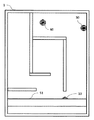
さらに、図8に示したように第二の飛行体30を飛行体10と同様に調査対象フロアの飛行体10から確認できる位置に固定し、飛行体10、第二の飛行体30を中継局として第三の飛行体60を飛行させることでさらに広いエリアの調査を行うことが可能となる。飛行体10や第二の飛行体30の固定は、フロアの高い位置の方が第三の飛行体60の監視が容易となる可能性が高いが、無線途絶の原因となる障害物が少ない場合は、床面51に着地させて、中継局として使用可能なことは明らかである。図8の例では、飛行体10は床面51に着地させている。
Further, as shown in FIG. 8, the second flying
以上説明した調査システムによれば、オペレータは目視やカメラの映像と飛行体に搭載したカメラの映像を見ながら、飛行体を遠隔操作して、調査対象近傍に固定し、飛行体に搭載したカメラの雲台を操作することで、飛行中と異なり安定した画像で調査が可能となる。さらに、調査対象があるフロアの無線が届く範囲に固定した第一の飛行体を中継局とし、第一の飛行体の雲台カメラの映像を使って第二の飛行体を飛行させることで、通信の途絶による操縦不能を防ぐことができ、調査範囲を拡大することができる。さらに、前記第一、第二の飛行体に無線の中継装置を搭載して無線の中継局とし、第三の飛行体を制御する方式とすることで、飛行体の移動可能範囲をさらに拡大して、調査範囲の拡大が可能となり、2次災害のリスクを抑えた調査を行うという目的は達成される。なお、いうまでもないが中継局とする飛行体の数に限定は無く3機以上の飛行体を中継局としても良い。 According to the survey system described above, the operator can remotely control the aircraft and fix it in the vicinity of the survey object while visually observing the video of the camera and the video of the camera mounted on the aircraft, and the camera mounted on the aircraft. By operating the pan head, it is possible to investigate with a stable image unlike in flight. In addition, by using the first flying object fixed within the range where the radio of the floor under investigation reaches as a relay station, the second flying object is made to fly using the image of the panoramic camera of the first flying object, Inability to control due to disruption of communication can be prevented, and the survey area can be expanded. In addition, a wireless relay station is mounted on the first and second flying bodies to form a wireless relay station, and the third flying body is controlled to further expand the movable range of the flying body. Therefore, the scope of the survey can be expanded, and the purpose of conducting a survey with a reduced risk of secondary disaster is achieved. Needless to say, the number of flying bodies as relay stations is not limited, and three or more flying bodies may be used as relay stations.
<付記>
なお、以上説明した実施形態は、
1.
周囲の状況を調査する調査装置を搭載し、飛行装置により飛行する飛行型調査機において、
前記飛行型調査機を任意の構造物に固定可能な固定装置と、
を備えた、
ことを特徴とする飛行型調査機、としたので、
・2次災害のリスクを避け、安全、確実に、長時間にわたる調査が可能な飛行型調査機を提供することができる。
・すなわち、本実施形態によれば、固定装置によって任意の構造物に固定することで、飛行装置を停止しても被固定箇所に停止していることができるので、飛行装置を停止してエネルギ消費を低減した状態で調査装置による調査を行うことができ、省エネルギで長時間にわたる調査が可能となる。
<Appendix>
The embodiment described above is
1.
In a flight type research aircraft equipped with a survey device that investigates the surrounding situation and flying with a flight device,
A fixing device capable of fixing the flight type research aircraft to an arbitrary structure;
With
Because it was a flight type research machine, characterized by
-It is possible to provide a flight-type research machine that can avoid the risk of secondary disasters, and can conduct surveys for a long time safely and reliably.
In other words, according to the present embodiment, by fixing to an arbitrary structure with the fixing device, even if the flying device is stopped, the flying device can be stopped at the fixed location. Investigation with the investigation device can be performed in a state where consumption is reduced, and the investigation can be performed for a long time with energy saving.
また本実施形態は、
2.
1.に記載の飛行型調査機において、
前記飛行装置を駆動する電源としてのバッテリと、
をさらに備えた、
ことを特徴とする飛行型調査機、としたので、
・固定装置によって任意の構造物に固定することで、飛行装置を停止しても被固定箇所に停止していることができるので、飛行装置を停止してバッテリ消費を低減した状態で調査装置による調査を行うことができ、長時間にわたる調査が可能となる。
In the present embodiment,
2.
1. In the flight type research aircraft described in
A battery as a power source for driving the flying device;
Further equipped with,
Because it was a flight type research machine, characterized by
-By fixing to any structure with a fixing device, even if the flying device is stopped, it can be stopped at the fixed place, so the investigation device is used with the flying device stopped and the battery consumption reduced Surveys can be conducted and surveys can be conducted for a long time.
また本実施形態は、
3.
1.に記載の飛行型調査機において、
前記固定装置による固定を解除可能な固定解除装置と、
をさらに備えた、
ことを特徴とする飛行型調査機、としたので、
・固定解除装置で固定を解除した後、飛行装置を動作させることで、再度、飛行することができる。
In the present embodiment,
3.
1. In the flight type research aircraft described in
A fixing release device capable of releasing the fixing by the fixing device;
Further equipped with,
Because it was a flight type research machine, characterized by
-After releasing the lock with the lock release device, it can fly again by operating the flight device.
また本実施形態は、
4.
1.に記載の飛行型調査機において、
該飛行型調査機に対する動作指示を外部から受信する動作指示受信装置と、
前記調査装置による調査結果を外部に送信する調査結果送信装置と、
をさらに備えた、
ことを特徴とする飛行型調査機、としたので、
・動作指示を送信する動作指示送信装置を有する端末装置によって、飛行型調査機を遠隔操作することができ、また、調査結果送信装置によって送信された調査結果を遠隔で受信することができ、より安全、確実な調査を実施することができる。
In the present embodiment,
4).
1. In the flight type research aircraft described in
An operation instruction receiving device for receiving an operation instruction for the flight type research aircraft from the outside;
A survey result transmitting device for transmitting a survey result by the survey device to the outside;
Further equipped with,
Because it was a flight type research machine, characterized by
・ The terminal device having an operation instruction transmission device that transmits an operation instruction can remotely control the flight-type survey machine, and can remotely receive the survey result transmitted by the survey result transmission device. A safe and reliable survey can be conducted.
また本実施形態は、
5.
1.に記載の飛行型調査機において、
前記飛行型調査機の外部から受信した信号を前記飛行型調査機の外部の所定の装置に送信する中継装置と、
をさらに備えた、
ことを特徴とする飛行型調査機、としたので、
・複数の飛行型調査機を用いて、中継装置によって中継することで、人間が操作する地点から、より遠方、より複雑な形状の地域の調査を行うことができる。
In the present embodiment,
5).
1. In the flight type research aircraft described in
A relay device for transmitting a signal received from the outside of the flight type research aircraft to a predetermined device outside the flight type research device;
Further equipped with,
Because it was a flight type research machine, characterized by
-By using a plurality of flight-type survey machines and relaying them by a relay device, it is possible to survey a region farther and more complicated from a point operated by a human.
また本実施形態は、
6.
1.に記載の飛行型調査機において、
前記飛行装置は、2重反転式プロペラによって飛行を行う装置である、
ことを特徴とする飛行型調査機、としたので、
・反トルクを相殺し、安定した飛行を行うことができる。
In the present embodiment,
6).
1. In the flight type research aircraft described in
The flying device is a device that performs flight with a double reversing propeller.
Because it was a flight type research machine, characterized by
・ Can counter-torque and perform stable flight.
また本実施形態は、
7.
3.に記載の飛行型調査機において、
前記固定装置は、磁石によって前記構造物に固定可能な装置である、
ことを特徴とする飛行型調査機、としたので、
・強磁性体、例えば鉄製の柱、壁、梁、天井、天井クレーン、その他の重機などに磁石で固定することによって、簡易な構成で飛行型調査機を固定することができる。固定装置の磁石は、電磁石であってもよいし、永久磁石であってもよい。固定装置の磁石が電磁石である場合には、固定解除装置は、電磁石への通電を停止することで固定を解除する装置であってもよい。
In the present embodiment,
7).
3. In the flight type research aircraft described in
The fixing device is a device that can be fixed to the structure by a magnet.
Because it was a flight type research machine, characterized by
-A flight type research machine can be fixed with a simple structure by fixing it to a ferromagnetic material such as an iron pillar, wall, beam, ceiling, overhead crane, or other heavy machine with a magnet. The magnet of the fixing device may be an electromagnet or a permanent magnet. When the magnet of the fixing device is an electromagnet, the fixing release device may be a device that releases the fixation by stopping energization of the electromagnet.
また本実施形態は、
8.
7.に記載の飛行型調査機において、
前記磁石は永久磁石である、
ことを特徴とする飛行型調査機、としたので、
・電磁石のように通電する構成が不要であり、簡易な構成で飛行型調査機を固定することができる。
In the present embodiment,
8).
7). In the flight type research aircraft described in
The magnet is a permanent magnet;
Because it was a flight type research machine, characterized by
・ A configuration that energizes like an electromagnet is unnecessary, and a flying survey machine can be fixed with a simple configuration.
また本実施形態は、
9.
8.に記載の飛行型調査機において、
前記固定解除装置は、前記構造物と前記永久磁石との間を離間させることで固定を解除する装置である、
ことを特徴とする飛行型調査機、としたので、
・固定解除装置は、被固定箇所と永久磁石との間を離間させることで確実に固定を解除することができ、簡易な構成で飛行型調査機を固定することができる。
In the present embodiment,
9.
8). In the flight type research aircraft described in
The fixation release device is a device that releases the fixation by separating the structure and the permanent magnet.
Because it was a flight type research machine, characterized by
-The fixing release device can reliably release the fixing by separating the fixed portion and the permanent magnet, and can fix the flying research machine with a simple configuration.
また本実施形態は、
10.
1.に記載の飛行型調査機において、
前記調査装置は、周囲の映像を撮影する撮影装置を含む、
ことを特徴とする飛行型調査機、としたので、
・人間が進入できない場所を撮影することができ、容易に状況把握をすることができる。
・また、飛行型調査機が、他の飛行型調査機に対する動作指示を受信し、該動作指示を該他の飛行型調査機に対して送信するとともに、該他の飛行型調査機からの調査結果を受信し、該調査結果を送信する中継装置をさらに備えた場合には、飛行型調査機が、周囲の映像を撮影する撮影装置によって他の飛行型調査機を撮影することで、他の飛行型調査機の周囲を映像で確認することができ、他の飛行型調査機を操縦しやすくすることができる。
In the present embodiment,
10.
1. In the flight type research aircraft described in
The investigation device includes a photographing device for photographing a surrounding image,
Because it was a flight type research machine, characterized by
・ It is possible to take pictures of places where humans cannot enter and to easily grasp the situation.
In addition, the flight type research aircraft receives an operation instruction for the other flight type research aircraft, transmits the operation instruction to the other flight type research aircraft, and investigates from the other flight type research aircraft. In the case of further comprising a relay device for receiving the result and transmitting the survey result, the flight type research machine photographs another flight type research machine with a photographing device that photographs the surrounding image, The surroundings of the flight type research aircraft can be confirmed on the video, and other flight type research aircraft can be easily operated.
また本実施形態は、
11.
4.に記載の飛行型調査機と、
操作者が操作する端末装置と、
を備え、
前記端末装置は、
操作者による前記飛行型調査機に対する動作指示の入力を受け付ける動作指示入力装置と、
前記動作指示入力装置で受け付けた動作指示を送信する動作指示送信装置と、
調査結果を受信する調査結果受信装置と、
を有する、
ことを特徴とする飛行型調査機を用いた調査システム、としたので、
・操作者は端末装置を操作することで、離れた場所にある飛行型調査機を操作することができ、より安全、確実な調査を実施することができる。
In the present embodiment,
11.
4). A flight type research machine as described in
A terminal device operated by an operator;
With
The terminal device
An operation instruction input device for receiving an operation instruction input to the flight type research aircraft by an operator;
An operation instruction transmitting device for transmitting an operation instruction received by the operation instruction input device;
A survey result receiving device for receiving the survey results;
Having
Because it was a survey system using a flight type survey machine characterized by that,
-By operating the terminal device, the operator can operate the flight type research machine located at a distant place, and can perform a safer and more reliable investigation.
また本実施形態は、
12.
周囲の状況を調査する調査装置を搭載し、飛行装置により飛行する飛行型調査機を用いた調査方法において、
前記飛行装置によって飛行した後、固定装置によって任意の構造物に固定し、
前記固定装置によって固定した状態で、前記調査装置によって周囲の調査を行う、
ことを特徴とする飛行型調査機を用いた調査方法、としたので、
・2次災害のリスクを避け、安全、確実に、長時間にわたる調査が可能な飛行型調査機を用いた調査方法を提供することができる。
In the present embodiment,
12
In the investigation method using the flight type research machine that carries the investigation device that investigates the surrounding situation and flies by the flying device,
After flying by the flying device, it is fixed to an arbitrary structure by a fixing device,
In the state fixed by the fixing device, the surroundings are investigated by the investigation device.
Because it was an investigation method using a flight type research machine characterized by that,
-It is possible to provide an investigation method using a flight type investigation machine that can avoid the risk of secondary disasters and can conduct a long-term investigation safely and reliably.
また実施形態は、
13.
12.に記載の飛行型調査機を用いた調査方法において、
複数の前記飛行型調査機を用い、
前記複数の飛行型調査機のうちの一は第一の飛行型調査機であり、
前記複数の飛行型調査機のうちの一は第二の飛行型調査機であり、
前記第一の飛行型調査機を前記固定装置によって任意の構造物に固定し、
前記第一の飛行型調査機を前記固定装置によって固定した状態で、該第一の飛行型調査機によって前記第二の飛行型調査機を撮影し、
操作者は、前記第一の飛行型調査機によって撮影した前記第二の飛行型調査機の映像を見ながら、前記第二の飛行型調査機を操縦する、
ことを特徴とする飛行型調査機を用いた調査方法、としたので、
・複数の飛行型調査機を用いて、第二の飛行型調査機の操縦をしやすくすることができる。
Also, the embodiment
13.
12 In the survey method using the flight type survey machine described in
Using a plurality of the flight type survey aircraft,
One of the plurality of flight-type survey aircraft is a first flight-type survey aircraft,
One of the plurality of flight-type survey aircraft is a second flight-type survey aircraft,
The first flight type research aircraft is fixed to an arbitrary structure by the fixing device,
In a state where the first flight type research machine is fixed by the fixing device, the second flight type research machine is photographed by the first flight type research machine,
The operator controls the second flight type research aircraft while viewing the video of the second flight type research aircraft taken by the first flight type research aircraft.
Because it was an investigation method using a flight type research machine characterized by that,
-It is possible to facilitate the operation of the second flight type research aircraft by using a plurality of flight type research aircraft.
以上説明したように、例えば災害により損傷した建屋や崩壊の可能性があるトンネル等の例えば閉空間の人手による調査では2次災害の危険が伴う。本実施形態によれば、このような閉空間の調査を2次災害のリスクを避けて、安全に調査することができる。さらに、工場、プラントではフロアの天井が高い場合も多く、調査対象が高所に存在する場合も多い。そのような対象を調査する場合、人が行ける場合でも調査時の2次災害のリスクは高くなる。さらに、建屋内に複数のフロアを持っている場合も、例えば、上層階フロアは移動に時間がかかるため放射線環境下である場合等は調査のリスクが高い。そのような場合にも本実施形態の飛行型調査機によれば安全に調査を実施することができる。 As described above, for example, a manual investigation in a closed space such as a building damaged by a disaster or a tunnel that may collapse may cause a risk of a secondary disaster. According to this embodiment, it is possible to investigate such a closed space safely while avoiding the risk of a secondary disaster. Furthermore, in many factories and plants, the ceiling of the floor is often high, and the survey target is often located at a high place. When investigating such objects, the risk of secondary disasters at the time of investigation increases even if people can go. Furthermore, even if there are multiple floors in the building, for example, the upper floors take a long time to move, so the risk of investigation is high if they are in a radiation environment. Even in such a case, according to the flight type research machine of this embodiment, it is possible to carry out the research safely.
なお、本発明は上記した実施例に限定されるものではなく、様々な変形例が含まれる。例えば、上記した実施例は本発明を分かりやすく説明するために詳細に説明したものであり、必ずしも説明した全ての構成を備えるものに限定されるものではない。また、ある実施例の構成の一部を他の実施例の構成に置き換えることが可能であり、また、ある実施例の構成に他の実施例の構成を加えることも可能である。また、各実施例の構成の一部について、他の構成の追加・削除・置換をすることが可能である。 In addition, this invention is not limited to an above-described Example, Various modifications are included. For example, the above-described embodiments have been described in detail for easy understanding of the present invention, and are not necessarily limited to those having all the configurations described. Further, a part of the configuration of one embodiment can be replaced with the configuration of another embodiment, and the configuration of another embodiment can be added to the configuration of one embodiment. Further, it is possible to add, delete, and replace other configurations for a part of the configuration of each embodiment.
10…飛行体、11…外殻、13…2重反転式プロペラ、14a、14b…プロペラ方向制御装置、15…バッテリ、17…雲台、18…カメラ、21…姿勢検出装置、22…固定装置、23…固定解除装置、24…無線中継機、25…映像中継機、30…第二の飛行体、40…遠隔制御装置。
DESCRIPTION OF
Claims (13)
前記飛行型調査機を任意の構造物に固定可能な固定装置と、
を備えた、
ことを特徴とする飛行型調査機。 In a flight type research aircraft equipped with a survey device that investigates the surrounding situation and flying with a flight device,
A fixing device capable of fixing the flight type research aircraft to an arbitrary structure;
With
A flight-type research machine characterized by that.
前記飛行装置を駆動する電源としてのバッテリと、
をさらに備えた、
ことを特徴とする飛行型調査機。 In the flight type research aircraft according to claim 1,
A battery as a power source for driving the flying device;
Further equipped with,
A flight-type research machine characterized by that.
前記固定装置による固定を解除可能な固定解除装置と、
をさらに備えた、
ことを特徴とする飛行型調査機。 In the flight type research aircraft according to claim 1,
A fixing release device capable of releasing the fixing by the fixing device;
Further equipped with,
A flight-type research machine characterized by that.
該飛行型調査機に対する動作指示を外部から受信する動作指示受信装置と、
前記調査装置による調査結果を外部に送信する調査結果送信装置と、
をさらに備えた、
ことを特徴とする飛行型調査機。 In the flight type research aircraft according to claim 1,
An operation instruction receiving device for receiving an operation instruction for the flight type research aircraft from the outside;
A survey result transmitting device for transmitting a survey result by the survey device to the outside;
Further equipped with,
A flight-type research machine characterized by that.
前記飛行型調査機の外部から受信した信号を前記飛行型調査機の外部の所定の装置に送信する中継装置と、
をさらに備えた、
ことを特徴とする飛行型調査機。 In the flight type research aircraft according to claim 1,
A relay device for transmitting a signal received from the outside of the flight type research aircraft to a predetermined device outside the flight type research device;
Further equipped with,
A flight-type research machine characterized by that.
前記飛行装置は、2重反転式プロペラによって飛行を行う装置である、
ことを特徴とする飛行型調査機。 In the flight type research aircraft according to claim 1,
The flying device is a device that performs flight with a double reversing propeller.
A flight-type research machine characterized by that.
前記固定装置は、磁石によって前記構造物に固定可能な装置である、
ことを特徴とする飛行型調査機。 In the flight type research aircraft according to claim 3,
The fixing device is a device that can be fixed to the structure by a magnet.
A flight-type research machine characterized by that.
前記磁石は永久磁石である、
ことを特徴とする飛行型調査機。 In the flight type research aircraft according to claim 7,
The magnet is a permanent magnet;
A flight-type research machine characterized by that.
前記固定解除装置は、前記構造物と前記永久磁石との間を離間させることで固定を解除する装置である、
ことを特徴とする飛行型調査機。 In the flight type research aircraft according to claim 8,
The fixation release device is a device that releases the fixation by separating the structure and the permanent magnet.
A flight-type research machine characterized by that.
前記調査装置は、周囲の映像を撮影する撮影装置を含む、
ことを特徴とする飛行型調査機。 In the flight type research aircraft according to claim 1,
The investigation device includes a photographing device for photographing a surrounding image,
A flight-type research machine characterized by that.
操作者が操作する端末装置と、
を備え、
前記端末装置は、
操作者による前記飛行型調査機に対する動作指示の入力を受け付ける動作指示入力装置と、
前記動作指示入力装置で受け付けた動作指示を送信する動作指示送信装置と、
調査結果を受信する調査結果受信装置と、
を有する、
ことを特徴とする飛行型調査機を用いた調査システム。 A flight type research aircraft according to claim 4;
A terminal device operated by an operator;
With
The terminal device
An operation instruction input device for receiving an operation instruction input to the flight type research aircraft by an operator;
An operation instruction transmitting device for transmitting an operation instruction received by the operation instruction input device;
A survey result receiving device for receiving the survey results;
Having
A survey system using a flight-type survey machine characterized by that.
前記飛行装置によって飛行した後、固定装置によって任意の構造物に固定し、
前記固定装置によって固定した状態で、前記調査装置によって周囲の調査を行う、
ことを特徴とする飛行型調査機を用いた調査方法。 In the investigation method using the flight type research machine that carries the investigation device that investigates the surrounding situation and flies by the flying device,
After flying by the flying device, it is fixed to an arbitrary structure by a fixing device,
In the state fixed by the fixing device, the surroundings are investigated by the investigation device.
A survey method using a flight type survey machine characterized by that.
複数の前記飛行型調査機を用い、
前記複数の飛行型調査機のうちの一は第一の飛行型調査機であり、
前記複数の飛行型調査機のうちの一は第二の飛行型調査機であり、
前記第一の飛行型調査機を前記固定装置によって任意の構造物に固定し、
前記第一の飛行型調査機を前記固定装置によって固定した状態で、該第一の飛行型調査機によって前記第二の飛行型調査機を撮影し、
操作者は、前記第一の飛行型調査機によって撮影した前記第二の飛行型調査機の映像を見ながら、前記第二の飛行型調査機を操縦する、
ことを特徴とする飛行型調査機を用いた調査方法。 In the survey method using the flight type survey machine according to claim 12,
Using a plurality of the flight type survey aircraft,
One of the plurality of flight-type survey aircraft is a first flight-type survey aircraft,
One of the plurality of flight-type survey aircraft is a second flight-type survey aircraft,
The first flight type research aircraft is fixed to an arbitrary structure by the fixing device,
In a state where the first flight type research machine is fixed by the fixing device, the second flight type research machine is photographed by the first flight type research machine,
The operator controls the second flight type research aircraft while viewing the video of the second flight type research aircraft taken by the first flight type research aircraft.
A survey method using a flight type survey machine characterized by that.
Priority Applications (1)
| Application Number | Priority Date | Filing Date | Title |
|---|---|---|---|
| JP2015245134A JP6664209B2 (en) | 2015-12-16 | 2015-12-16 | Investigation method using flight-type survey aircraft |
Applications Claiming Priority (1)
| Application Number | Priority Date | Filing Date | Title |
|---|---|---|---|
| JP2015245134A JP6664209B2 (en) | 2015-12-16 | 2015-12-16 | Investigation method using flight-type survey aircraft |
Publications (2)
| Publication Number | Publication Date |
|---|---|
| JP2017109593A true JP2017109593A (en) | 2017-06-22 |
| JP6664209B2 JP6664209B2 (en) | 2020-03-13 |
Family
ID=59079949
Family Applications (1)
| Application Number | Title | Priority Date | Filing Date |
|---|---|---|---|
| JP2015245134A Active JP6664209B2 (en) | 2015-12-16 | 2015-12-16 | Investigation method using flight-type survey aircraft |
Country Status (1)
| Country | Link |
|---|---|
| JP (1) | JP6664209B2 (en) |
Cited By (6)
| Publication number | Priority date | Publication date | Assignee | Title |
|---|---|---|---|---|
| JP2018100063A (en) * | 2016-12-22 | 2018-06-28 | 学校法人早稲田大学 | Movable body, and remote inspection system using the same, and remote inspection method in pipe |
| JP2019132611A (en) * | 2018-01-29 | 2019-08-08 | 日立Geニュークリア・エナジー株式会社 | Investigation system and method for investigation |
| JP2020017833A (en) * | 2018-07-25 | 2020-01-30 | 公立大学法人大阪 | Network system and communication method |
| JP2020519525A (en) * | 2017-12-15 | 2020-07-02 | 大韓民国 行政安全部 国立災難安全研究院Republic Of Korea (National Disaster Management Research Institute) | Floating type air condition detector capable of staying in the air |
| JP2021502920A (en) * | 2017-11-14 | 2021-02-04 | フライボティックス ソシエテアノニムFlybotix SA | For example, a system that forms a two-degree-of-freedom actuator that changes the pitch angle of the propeller blades during rotation. |
| JP7397608B2 (en) | 2019-09-19 | 2023-12-13 | Ihi運搬機械株式会社 | drone port |
Citations (7)
| Publication number | Priority date | Publication date | Assignee | Title |
|---|---|---|---|---|
| JP2006051893A (en) * | 2004-08-12 | 2006-02-23 | Seiko Epson Corp | Position/posture detecting system |
| JP2013531573A (en) * | 2010-05-26 | 2013-08-08 | エアロヴァイロンメント インコーポレイテッド | Reconfigurable battery-powered drone system |
| JP2015101168A (en) * | 2013-11-22 | 2015-06-04 | 国立大学法人東北大学 | Flight device |
| JP2015178294A (en) * | 2014-03-19 | 2015-10-08 | 特定非営利活動法人 国際レスキューシステム研究機構 | Flight device |
| DE102014005838A1 (en) * | 2014-04-19 | 2015-10-22 | Mbda Deutschland Gmbh | Unmanned small aircraft and method for landing a small aircraft |
| JP2015194069A (en) * | 2014-03-27 | 2015-11-05 | 株式会社フジタ | Inspection device for structure |
| JP2015217785A (en) * | 2014-05-16 | 2015-12-07 | 株式会社日立製作所 | Control method of unmanned rotary wing flying body |
-
2015
- 2015-12-16 JP JP2015245134A patent/JP6664209B2/en active Active
Patent Citations (7)
| Publication number | Priority date | Publication date | Assignee | Title |
|---|---|---|---|---|
| JP2006051893A (en) * | 2004-08-12 | 2006-02-23 | Seiko Epson Corp | Position/posture detecting system |
| JP2013531573A (en) * | 2010-05-26 | 2013-08-08 | エアロヴァイロンメント インコーポレイテッド | Reconfigurable battery-powered drone system |
| JP2015101168A (en) * | 2013-11-22 | 2015-06-04 | 国立大学法人東北大学 | Flight device |
| JP2015178294A (en) * | 2014-03-19 | 2015-10-08 | 特定非営利活動法人 国際レスキューシステム研究機構 | Flight device |
| JP2015194069A (en) * | 2014-03-27 | 2015-11-05 | 株式会社フジタ | Inspection device for structure |
| DE102014005838A1 (en) * | 2014-04-19 | 2015-10-22 | Mbda Deutschland Gmbh | Unmanned small aircraft and method for landing a small aircraft |
| JP2015217785A (en) * | 2014-05-16 | 2015-12-07 | 株式会社日立製作所 | Control method of unmanned rotary wing flying body |
Cited By (8)
| Publication number | Priority date | Publication date | Assignee | Title |
|---|---|---|---|---|
| JP2018100063A (en) * | 2016-12-22 | 2018-06-28 | 学校法人早稲田大学 | Movable body, and remote inspection system using the same, and remote inspection method in pipe |
| JP2021502920A (en) * | 2017-11-14 | 2021-02-04 | フライボティックス ソシエテアノニムFlybotix SA | For example, a system that forms a two-degree-of-freedom actuator that changes the pitch angle of the propeller blades during rotation. |
| JP7217543B2 (en) | 2017-11-14 | 2023-02-03 | フライボティックス ソシエテアノニム | A system that forms a two-degree-of-freedom actuator, e.g. to change the pitch angle of the blades of a propeller during rotation |
| JP2020519525A (en) * | 2017-12-15 | 2020-07-02 | 大韓民国 行政安全部 国立災難安全研究院Republic Of Korea (National Disaster Management Research Institute) | Floating type air condition detector capable of staying in the air |
| US11733226B2 (en) | 2017-12-15 | 2023-08-22 | National Disaster Management Institute | Air state detection floating device capable of remaining in air |
| JP2019132611A (en) * | 2018-01-29 | 2019-08-08 | 日立Geニュークリア・エナジー株式会社 | Investigation system and method for investigation |
| JP2020017833A (en) * | 2018-07-25 | 2020-01-30 | 公立大学法人大阪 | Network system and communication method |
| JP7397608B2 (en) | 2019-09-19 | 2023-12-13 | Ihi運搬機械株式会社 | drone port |
Also Published As
| Publication number | Publication date |
|---|---|
| JP6664209B2 (en) | 2020-03-13 |
Similar Documents
| Publication | Publication Date | Title |
|---|---|---|
| JP6664209B2 (en) | Investigation method using flight-type survey aircraft | |
| JP6085153B2 (en) | Indoor survey system | |
| JP6594640B2 (en) | Monitoring system | |
| US20200064845A1 (en) | Unmanned aerial vehicle and moving object capturing system | |
| KR101894409B1 (en) | Drone control system and method | |
| JP6278539B2 (en) | Flight mode selection based on situation | |
| CN107531217B (en) | Apparatus and method for identifying or detecting obstacles | |
| KR101739262B1 (en) | The unmanned air vehicle for castaway tracking | |
| Bosscher et al. | A concept for rapidly-deployable cable robot search and rescue systems | |
| JP6539072B2 (en) | Surveillance system and flight robot | |
| KR20210066875A (en) | Air vehicle having countermeasures to neutralize target air vehicle | |
| JP4613345B2 (en) | Sensor network robot system | |
| US20170073071A1 (en) | Unmanned aircraft and unmanned ground vehicle teaming for remote infrastructure inspection | |
| KR101645309B1 (en) | Apparatus for disaster observation of knapsack type using unmanned air vehicle | |
| US20100179691A1 (en) | Robotic Platform | |
| KR102170703B1 (en) | Fire fighter drone for fire fighter and scout | |
| JP2017226259A (en) | Flying object for inspecting pipeline facility and system for inspecting pipeline facility using the same | |
| JP6080568B2 (en) | Monitoring system | |
| JP6509599B2 (en) | Flight robot control system and flight robot | |
| JP6578113B2 (en) | Flying robot control system and flying robot | |
| CA3078994C (en) | Method and system of an surface attachment of modular unmanned aerial vehicle for inspection | |
| JP4670052B2 (en) | Flying robot control device and flying robot control method | |
| JP6846698B2 (en) | Monitoring device | |
| JP2018055362A (en) | Monitoring system | |
| JP2021138204A (en) | Device and method for surveying inside building |
Legal Events
| Date | Code | Title | Description |
|---|---|---|---|
| A621 | Written request for application examination |
Free format text: JAPANESE INTERMEDIATE CODE: A621 Effective date: 20180822 |
|
| A977 | Report on retrieval |
Free format text: JAPANESE INTERMEDIATE CODE: A971007 Effective date: 20190724 |
|
| A131 | Notification of reasons for refusal |
Free format text: JAPANESE INTERMEDIATE CODE: A131 Effective date: 20190806 |
|
| A521 | Request for written amendment filed |
Free format text: JAPANESE INTERMEDIATE CODE: A523 Effective date: 20190903 |
|
| TRDD | Decision of grant or rejection written | ||
| A01 | Written decision to grant a patent or to grant a registration (utility model) |
Free format text: JAPANESE INTERMEDIATE CODE: A01 Effective date: 20200212 |
|
| A61 | First payment of annual fees (during grant procedure) |
Free format text: JAPANESE INTERMEDIATE CODE: A61 Effective date: 20200218 |
|
| R150 | Certificate of patent or registration of utility model |
Ref document number: 6664209 Country of ref document: JP Free format text: JAPANESE INTERMEDIATE CODE: R150 |