JP2017107829A - Battery attachment apparatus - Google Patents

Battery attachment apparatus Download PDF

Info

Publication number
JP2017107829A
JP2017107829A JP2016071244A JP2016071244A JP2017107829A JP 2017107829 A JP2017107829 A JP 2017107829A JP 2016071244 A JP2016071244 A JP 2016071244A JP 2016071244 A JP2016071244 A JP 2016071244A JP 2017107829 A JP2017107829 A JP 2017107829A
Authority
JP
Japan
Prior art keywords
battery
case
lid member
hole
attachment
Prior art date
Legal status (The legal status is an assumption and is not a legal conclusion. Google has not performed a legal analysis and makes no representation as to the accuracy of the status listed.)
Granted
Application number
JP2016071244A
Other languages
Japanese (ja)
Other versions
JP6713318B2 (en
Inventor
裕紀 小倉
Hiroki Ogura
裕紀 小倉
秀行 田賀
Hideyuki Taga
秀行 田賀
Current Assignee (The listed assignees may be inaccurate. Google has not performed a legal analysis and makes no representation or warranty as to the accuracy of the list.)
Makita Corp
Original Assignee
Makita Corp
Priority date (The priority date is an assumption and is not a legal conclusion. Google has not performed a legal analysis and makes no representation as to the accuracy of the date listed.)
Filing date
Publication date
Application filed by Makita Corp filed Critical Makita Corp
Priority to US15/356,782 priority Critical patent/US10461380B2/en
Priority to CN201611060707.7A priority patent/CN107068923B/en
Priority to EP16200809.8A priority patent/EP3176904B1/en
Publication of JP2017107829A publication Critical patent/JP2017107829A/en
Application granted granted Critical
Publication of JP6713318B2 publication Critical patent/JP6713318B2/en
Active legal-status Critical Current
Anticipated expiration legal-status Critical

Links

Images

Classifications

    • HELECTRICITY
    • H01ELECTRIC ELEMENTS
    • H01MPROCESSES OR MEANS, e.g. BATTERIES, FOR THE DIRECT CONVERSION OF CHEMICAL ENERGY INTO ELECTRICAL ENERGY
    • H01M50/00Constructional details or processes of manufacture of the non-active parts of electrochemical cells other than fuel cells, e.g. hybrid cells
    • H01M50/20Mountings; Secondary casings or frames; Racks, modules or packs; Suspension devices; Shock absorbers; Transport or carrying devices; Holders
    • YGENERAL TAGGING OF NEW TECHNOLOGICAL DEVELOPMENTS; GENERAL TAGGING OF CROSS-SECTIONAL TECHNOLOGIES SPANNING OVER SEVERAL SECTIONS OF THE IPC; TECHNICAL SUBJECTS COVERED BY FORMER USPC CROSS-REFERENCE ART COLLECTIONS [XRACs] AND DIGESTS
    • Y02TECHNOLOGIES OR APPLICATIONS FOR MITIGATION OR ADAPTATION AGAINST CLIMATE CHANGE
    • Y02EREDUCTION OF GREENHOUSE GAS [GHG] EMISSIONS, RELATED TO ENERGY GENERATION, TRANSMISSION OR DISTRIBUTION
    • Y02E60/00Enabling technologies; Technologies with a potential or indirect contribution to GHG emissions mitigation
    • Y02E60/10Energy storage using batteries

Landscapes

  • Chemical & Material Sciences (AREA)
  • Chemical Kinetics & Catalysis (AREA)
  • Electrochemistry (AREA)
  • General Chemical & Material Sciences (AREA)
  • Battery Mounting, Suspending (AREA)
  • Charge And Discharge Circuits For Batteries Or The Like (AREA)
  • Secondary Cells (AREA)

Abstract

PROBLEM TO BE SOLVED: To provide a battery attachment apparatus to which an electric tool battery is detachably attached, the battery attachment apparatus preventing a malfunction of products by preventing intrusion of foreign matters and static electricity from the exterior of a case into the interior thereof through a wall-hanging lock hole while the lock hole is provided.SOLUTION: A battery attachment apparatus includes a battery attachment section to which an electric tool battery is detachably attached, and a case 20 as an exterior portion thereof. The case 20 is provided with a lock hole 31 establishing communication between the exterior and interior of the case 20 to allow an external male screw to be locked. A cover member 70 is attached to a mounting portion 40 that is set on an inner surface 201 of the case 20. The cover member 70 works to close an opening of the lock hole 31 from the inner side of the case 20. The cover member 70 prevents intrusion of foreign matters and static electricity from the exterior of the case 20 into the interior of the case 20 through the lock hole 31.SELECTED DRAWING: Figure 5

Description

本発明は、電動工具用バッテリが着脱されるバッテリ装着器に関する。   The present invention relates to a battery mounter to which a power tool battery is attached and detached.

昨今、電動工具の駆動電源として電動工具用バッテリが利用されている。このような電動工具用バッテリは、充電残量が少なくなると工具本体から取り外されて専用の充電器に装着されて充電される(例えば特許文献1参照)。他方、バッテリチェッカとも称され、電動工具用バッテリの異常を点検する専用の診断器が知られている。このような診断器は、装着された電動工具用バッテリの、バッテリ充電回数、バッテリ電圧、バッテリ内部抵抗を診断した結果、バッテリ容量を診断した結果、このほか電動工具用バッテリを総合的に診断した結果などのバッテリ状態を検出し、ユーザに表示出力するように構成される。   Recently, a power tool battery is used as a driving power source of the power tool. Such a battery for electric tools is removed from the tool body and charged by being attached to a dedicated charger when the remaining charge level is low (see, for example, Patent Document 1). On the other hand, there is also known as a battery checker and a dedicated diagnostic device for checking an abnormality of a power tool battery. Such a diagnostic device diagnoses the number of times the battery is charged, the battery voltage, and the internal resistance of the installed power tool battery, as well as the battery capacity, and comprehensively diagnoses the power tool battery. A battery state such as a result is detected and displayed to the user.

上記した充電器や診断器は、ともに電動工具用バッテリが着脱される機器として構成される。以下、このような電動工具用バッテリが着脱される工具以外の機器をバッテリ装着器と総称する。このようなバッテリ装着器は、使用上の利便性から壁に掛けておきたい場合がある。このような壁掛け式のバッテリ装着器とするには、ケースに設けられた掛止孔に、壁に取り付けられた壁掛け用の螺子を差し込んで掛けることができるようにしてある(例えば特許文献2参照)。なお、この掛止孔は、ケースの外部とケースの内部とを連通して設けられている。この掛止孔は、プラスチック(合成樹脂)を材料としてケースを成形する際に、その他のケースの外装形状と共に一緒に成形されている。   Both the charger and the diagnostic device described above are configured as devices to which a power tool battery is attached and detached. Hereinafter, devices other than the tool to / from which such a power tool battery is attached / detached are collectively referred to as a battery mounter. In some cases, such a battery mounter is desired to be hung on a wall for convenience of use. In such a wall-mounted battery mounting device, a wall-hanging screw attached to a wall can be inserted into a hook hole provided in the case so as to be hung (see, for example, Patent Document 2). ). The retaining hole is provided so that the outside of the case communicates with the inside of the case. When the case is molded using plastic (synthetic resin) as a material, the retaining hole is molded together with the exterior shape of the other case.

特開2004−147360号公報JP 2004-147360 A 実開平4−004446号公報Japanese Utility Model Publication No. 4-004446

ところで、上記した掛止孔は、ケースの外部とケースの内部とを連通して設けられる。このため、この掛止孔を通じて、ケースの外部からケースの内部に異物が侵入してしまったり、この掛止孔を通じて、ケースの外部からケースの内部に静電気が入ってきて内装の電子部品に悪影響を与えてしまったりすることがある。なお、このような問題は、バッテリ装着器として小型化が図られてきた昨今では、より顕著な問題となりつつある。   By the way, the above-mentioned latching hole is provided in communication with the outside of the case and the inside of the case. For this reason, foreign matter enters the inside of the case from the outside of the case through this retaining hole, or static electricity enters the inside of the case from the outside of the case through this retaining hole, adversely affecting the electronic components in the interior. May be given. Note that such a problem is becoming a more prominent problem nowadays as a battery mounting device has been reduced in size.

本発明は、このような事情に鑑みなされたものであって、本発明が解決しようとする課題は、電動工具用バッテリが着脱されるバッテリ装着器において、壁掛け用の掛止孔を設けつつも、掛止孔を通じてケースの外部からケースの内部に異物や静電気の侵入してくるのを防いで製品の誤作動防止を図ることにある。   The present invention has been made in view of the above circumstances, and the problem to be solved by the present invention is to provide a battery mounting device to which a battery for a power tool is attached and detached while providing a retaining hole for hanging on a wall. The purpose of this is to prevent foreign products and static electricity from entering the inside of the case from the outside of the case through the retaining holes, thereby preventing malfunction of the product.

上記した課題を解決するにあたって、本発明に係るバッテリ装着器は次の手段をとる。すなわち、本発明の第1の発明に係るバッテリ装着器は、電動工具用バッテリが着脱されるバッテリ装着器であって、外装としてのケースを有し、前記ケースには、該ケースの内外を連通して外部の掛止部材を掛止可能とする掛止孔が設けられており、前記掛止孔の開口を前記ケースの内部側から閉じる蓋部材が、前記ケースの内面に設定される取付部に取り付けられている、という構成である。   In solving the above-described problems, the battery mounter according to the present invention takes the following means. That is, the battery mounting device according to the first aspect of the present invention is a battery mounting device to which a battery for an electric tool is attached and detached, and has a case as an exterior, and the case communicates with the inside and outside of the case. A mounting hole is provided on the inner surface of the case, wherein a latching hole is provided to allow the latching of the external latching member, and the lid member that closes the opening of the latching hole from the inner side of the case It is the structure of being attached to.

この第1の発明に係るバッテリ装着器によれば、外部の掛止部材として例えば壁に取り付けられた壁掛け用の螺子を掛止孔に差し込んでバッテリ装着器を壁に掛けておくことができる。これによって、壁掛け式のバッテリ装着器とすることができる。ここで、取付部に取り付けられた蓋部材は、掛止孔の開口をケースの内部側から閉じることができる。これによって、蓋部材は、ケースの外部からケースの内部に掛止孔を通じて異物や静電気の侵入してくるのを防いで、この異物や静電気が侵入することによる製品の誤作動を防止することができる。   According to the battery mounting device according to the first aspect of the present invention, the battery mounting device can be hung on the wall by inserting, for example, a wall-hanging screw attached to the wall as an external locking member into the locking hole. Thereby, it can be set as a wall-mounted battery mounting device. Here, the lid member attached to the attachment portion can close the opening of the latching hole from the inside of the case. As a result, the lid member prevents foreign matter and static electricity from entering the case through the retaining hole from the outside of the case, and prevents malfunction of the product due to the entry of this foreign matter and static electricity. it can.

本発明の第2の発明に係るバッテリ装着器は、前記第1の発明に係るバッテリ装着器において、前記取付部は、前記掛止孔と対面する位置まで延びる取付支持部を有し、前記取付支持部は、取り付けられた前記蓋部材を内側から前記掛止孔に向けて支持する、という構成である。この第2の発明に係るバッテリ装着器によれば、取付支持部は掛止孔と対面する位置に設けられて蓋部材を内側から掛止孔に向けて支持する。これによって、異物が掛止孔を通じて蓋部材を押すようなことがあっても、蓋部材は取付支持部にて支持されて外れ難くなる。したがって、外部からの異物の侵入にも蓋部材は強固に支持されることとなり、製品の誤作動を強力に防止することができる。   The battery mounting device according to a second aspect of the present invention is the battery mounting device according to the first aspect, wherein the mounting portion has a mounting support portion extending to a position facing the retaining hole, and the mounting The support portion is configured to support the attached lid member from the inside toward the retaining hole. According to the battery mounting device according to the second aspect of the present invention, the attachment support portion is provided at a position facing the latching hole and supports the lid member from the inside toward the latching hole. As a result, even if a foreign object pushes the lid member through the retaining hole, the lid member is supported by the mounting support portion and is difficult to come off. Therefore, the lid member is firmly supported even when foreign matter enters from the outside, and the malfunction of the product can be strongly prevented.

本発明の第3の発明に係るバッテリ装着器は、前記第2の発明に係るバッテリ装着器において、前記取付部に対する前記蓋部材の取付け方向は、前記ケースの内面に沿った内面延在方向に設定されている、という構成である。この第3の発明に係るバッテリ装着器によれば、取付部に対する蓋部材の取付け方向はケースの内面に沿った内面延在方向に設定されているので、取付支持部の存在が邪魔にならずに蓋部材を取付部に取り付けることができる。これによって、取付部に対する蓋部材の取付けを簡単かつ確実に行うことができる。   The battery mounting device according to a third aspect of the present invention is the battery mounting device according to the second aspect, wherein the mounting direction of the lid member with respect to the mounting portion is an inner surface extending direction along the inner surface of the case. The configuration is set. In the battery mounting device according to the third aspect of the invention, the attachment direction of the lid member with respect to the attachment portion is set to the inner surface extending direction along the inner surface of the case, so the presence of the attachment support portion does not interfere. The lid member can be attached to the attachment portion. Accordingly, the lid member can be easily and reliably attached to the attachment portion.

本発明の第4の発明に係るバッテリ装着器は、前記第3の発明に係るバッテリ装着器において、前記蓋部材には、前記取付支持部を嵌め込む構造が設けられている、という構成である。この第4の発明に係るバッテリ装着器によれば、蓋部材には取付支持部を嵌め込む構造が設けられているので、取付支持部による蓋部材の支持を高めることができる。これによって、取付部に対する蓋部材の取付けをより確実にすることができる。   According to a fourth aspect of the present invention, there is provided a battery attachment device according to the third aspect, wherein the lid member is provided with a structure for fitting the attachment support portion. . According to the battery mounting device of the fourth aspect of the present invention, since the lid member is provided with the structure for fitting the attachment support portion, the support of the lid member by the attachment support portion can be enhanced. Thereby, the attachment of the lid member to the attachment portion can be made more reliable.

本発明の第5の発明に係るバッテリ装着器は、前記第3または前記第4の発明に係るバッテリ装着器において、前記取付部は、該取付部に対する前記蓋部材の外しを規制する外し規制部を有し、前記取付支持部は、弾性変形することにより前記外し規制部を越えて前記取付部に対する前記蓋部材の取付けを許容する、という構成である。この第5の発明に係るバッテリ装着器によれば、外し規制部により取付部に対する蓋部材の外しを規制することができる。これによって、取付部に対する蓋部材の取付け状態を強固に保持することができる。なお、このように設けられる外し規制部は、取付支持部の弾性変形によって取付支持部に干渉されることなく蓋部材の取付けを行うことができるので、蓋部材の取付けも容易に行うことができる。   The battery mounting device according to a fifth aspect of the present invention is the battery mounting device according to the third or fourth aspect of the present invention, wherein the mounting portion is a removal restricting portion that restricts the removal of the lid member with respect to the mounting portion. The attachment support part is configured to allow attachment of the lid member to the attachment part beyond the removal restricting part by elastic deformation. According to the battery mounting device of the fifth aspect of the invention, the removal of the lid member with respect to the attachment portion can be restricted by the removal restriction portion. Thereby, the attachment state of the lid member to the attachment portion can be firmly held. In addition, since the removal restricting portion provided in this way can attach the lid member without being interfered by the attachment support portion due to the elastic deformation of the attachment support portion, the lid member can also be easily attached. .

本発明の第6の発明に係るバッテリ装着器は、前記第1から前記第5のいずれかの発明に係るバッテリ装着器において、前記取付部に対する前記蓋部材の取付け方向は、上から下に向けた方向である、という構成である。この第6の発明に係るバッテリ装着器によれば、取付部に対する蓋部材の取付け方向は上から下に向けた方向であるので、蓋部材に対しての重力作用は蓋部材の取付け方向と一致することとなる。これによって、蓋部材の外れを抑えることができる。   A battery mounting device according to a sixth aspect of the present invention is the battery mounting device according to any one of the first to fifth aspects, wherein the mounting direction of the lid member relative to the mounting portion is from top to bottom. It is the structure that it is the direction. According to the battery mounting device of the sixth aspect of the invention, the direction of attachment of the lid member to the attachment portion is the direction from top to bottom, so that the gravity action on the lid member coincides with the direction of attachment of the lid member. Will be. Thereby, the detachment of the lid member can be suppressed.

本発明の第7の発明に係るバッテリ装着器は、前記第1から前記第6のいずれかの発明に係るバッテリ装着器において、前記蓋部材には、前記取付部に設けられる縁部と板厚方向で重なる壁部が設けられている、という構成である。この第7の発明に係るバッテリ装着器によれば、蓋部材には取付部に設けられる縁部と板厚方向で重なる壁部が設けられているので、掛止孔の開口の縁部分をオーバーラップさせて閉じることができる。これによって、掛止孔からケースの内部への閉塞沿面距離を延ばして密閉性を高めている。したがって、掛止孔からケースの内部への異物や静電気の侵入をより抑えることができる。   The battery mounting device according to a seventh aspect of the present invention is the battery mounting device according to any one of the first to sixth aspects, wherein the lid member has an edge portion and a plate thickness provided in the mounting portion. It is the structure that the wall part which overlaps in a direction is provided. According to the battery mounting device of the seventh aspect of the invention, since the lid member is provided with the wall portion that overlaps the edge portion provided in the attachment portion in the thickness direction, the edge portion of the opening of the latching hole is overloaded. It can be wrapped and closed. Thereby, the closing creepage distance from the retaining hole to the inside of the case is extended to improve the sealing performance. Therefore, it is possible to further suppress the intrusion of foreign matter and static electricity from the retaining hole into the case.

本発明の第8の発明に係るバッテリ装着器は、前記第1から前記第7のいずれかの発明に係るバッテリ装着器において、前記掛止部材は、壁に埋め込んで支持される脚部と、該脚部の外径より拡大した外径の掛止頭部と、を有し、前記掛止孔は、前記掛止頭部が差込可能とされる第1孔部と、差し込まれた前記掛止頭部の抜けが規制されるように前記第1孔部よりも短い内径の第2孔部とが、下と上との関係で連ねられて形成されている、という構成である。この第8の発明に係るバッテリ装着器によれば、外部の掛止部材として例えば壁に取り付けられた壁掛け用の雄螺子や壁掛け用の釘などを掛止孔に差し込んで、バッテリ装着器を壁に掛けておくことができる。これによって、一般的な雄螺子を掛止部材として利用して、壁掛け式のバッテリ装着器とすることができる。   The battery mounting device according to an eighth aspect of the present invention is the battery mounting device according to any one of the first to seventh inventions, wherein the hooking member is embedded in a wall and supported by a leg, A latching head having an outer diameter that is larger than the outer diameter of the leg, and the latching hole is inserted into the first hole in which the latching head can be inserted. The second hole portion having an inner diameter shorter than that of the first hole portion is formed so as to be connected in a relationship between the lower side and the upper side so that the latch head is prevented from coming off. According to the battery mounting device according to the eighth aspect of the present invention, for example, a wall mounting male screw or a wall mounting nail attached to the wall is inserted into the locking hole as an external locking member, and the battery mounting device is mounted on the wall. Can be hung on. Thus, a wall-mounted battery mounting device can be obtained by using a general male screw as a locking member.

バッテリチェッカの表側からの斜視図である。It is a perspective view from the front side of a battery checker. バッテリチェッカに電動工具用バッテリを装着しようとする斜視図である。It is a perspective view which tries to mount | wear the battery checker with the battery for electric tools. バッテリチェッカの裏側からの斜視図である。It is a perspective view from the back side of a battery checker. ケース内部側から視た掛止構造を示す斜視図である。It is a perspective view which shows the latching structure seen from the case inside side. 取付部に蓋部材を取り付けようとする掛止構造を示す斜視図である。It is a perspective view which shows the latching structure which is going to attach a cover member to an attaching part. 蓋部材が取り付けられていない取付部を示す斜視図である。It is a perspective view which shows the attaching part to which the cover member is not attached. 別の角度から視た図6の取付部を示す斜視図である。It is a perspective view which shows the attaching part of FIG. 6 seen from another angle. 蓋部材が取り付けられていない取付部を示す正面図である。It is a front view which shows the attaching part to which the cover member is not attached. 蓋部材が取り付けられていない取付部を示す左側面図である。It is a left view which shows the attaching part to which the cover member is not attached. 蓋部材が取り付けられていない取付部を示す上面図である。It is a top view which shows the attaching part to which the cover member is not attached. 外部から視た掛止孔を示す正面図である。It is a front view which shows the latching hole seen from the outside. 蓋部材の単品外部形状を示す斜視図である。It is a perspective view which shows the single-piece external shape of a cover member. 別の角度から視た蓋部材の単品外部形状を示す斜視図である。It is a perspective view which shows the single-piece external shape of the cover member seen from another angle. 蓋部材の単品内部形状を示す斜視図である。It is a perspective view which shows the single-piece internal shape of a cover member. 蓋部材の外部を示す正面図である。It is a front view which shows the exterior of a cover member. 蓋部材を示す左側面図である。It is a left view which shows a cover member. 取付部に蓋部材が取り付けられた掛止構造を示す正面図である。It is a front view which shows the latching structure where the cover member was attached to the attaching part. 図17の掛止構造を示す左側面図である。It is a left view which shows the latching structure of FIG. 図17の掛止構造を示す上面図である。It is a top view which shows the latching structure of FIG. 図17の(XX)-(XX)線断面矢視図である。It is the (XX)-(XX) sectional view taken on the line of FIG. 図18の(XXI)-(XXI)線断面矢視図である。It is the (XXI)-(XXI) sectional view taken on the line of FIG. 図17の(XXII)-(XXII)線断面矢視図である。It is the (XXII)-(XXII) sectional view taken on the line of FIG. 図17の(XXIII)-(XXIII)線断面矢視図である。It is the (XXIII)-(XXIII) sectional view taken on the line of FIG. 雄螺子が差し込まれた掛止孔を示す外部斜視図である。It is an external perspective view which shows the latching hole in which the male screw was inserted. 図24の(XXV)-(XXV)線断面矢視図である。It is the (XXV)-(XXV) sectional view taken on the line of FIG. 雄螺子が掛止された掛止孔を示す外部斜視図である。It is an external perspective view which shows the latching hole by which the male screw was latched. 図26の(XXVII)-(XXVII)線断面矢視図である。FIG. 27 is a sectional view taken along line (XXVII)-(XXVII) in FIG. 26. 表ケースと表示出力部の表側からの分解斜視図である。It is a disassembled perspective view from the front side of a front case and a display output part. 表ケースと表示出力部の裏側からの分解斜視図である。It is a disassembled perspective view from the back side of a front case and a display output part. 表ケースと表示出力部の裏面図である。It is a back view of a front case and a display output part. 図1の(XXXI)-(XXXI)線断面矢視図である。It is the (XXXI)-(XXXI) sectional view taken on the line of FIG. 図1の(XXXII)-(XXXII)線断面矢視図である。It is the (XXXII)-(XXXII) sectional view taken on the line of FIG. 裏ケースと該裏ケースに装着された部品の表面図である。FIG. 6 is a surface view of a back case and components mounted on the back case. バッテリチェッカの上面図である。It is a top view of a battery checker. バッテリチェッカの上面図である。It is a top view of a battery checker. バッテリチェッカのブロック図である。It is a block diagram of a battery checker.

以下、本発明に係るバッテリ装着器を実施するための実施の形態について図1〜図27を参照しながら説明する。図1〜図3では、本発明に係るバッテリ装着器としてのバッテリチェッカ10を図示している。図1はバッテリチェッカ10の表側を示している。図2は電動工具用バッテリBを装着しようとする斜視図であり、図3はバッテリチェッカ10の裏側を示している。バッテリチェッカ10は、電動工具用バッテリBが着脱される電気機器である。このバッテリチェッカ10は、通常はバッテリ装着部11に装着された電動工具用バッテリBからの電力供給により駆動し、電動工具用バッテリBからの電力供給が無い場合に乾電池収容部23(図3参照)に収容された乾電池により駆動可能にされている。このバッテリチェッカ10は、例えば、屋内の壁に固定された雄螺子に掛けられる壁掛け式で構成されている。このため、以下の説明では、壁に掛けられたバッテリチェッカ10にて規定される『表裏上下左右』の方向に基づいて、バッテリチェッカ10を説明することとする。   Hereinafter, an embodiment for carrying out a battery mounter according to the present invention will be described with reference to FIGS. 1-3, the battery checker 10 as a battery mounting device which concerns on this invention is shown in figure. FIG. 1 shows the front side of the battery checker 10. FIG. 2 is a perspective view of the electric tool battery B to be mounted, and FIG. 3 shows the back side of the battery checker 10. The battery checker 10 is an electric device to which the electric tool battery B is attached and detached. The battery checker 10 is normally driven by power supply from the power tool battery B mounted on the battery mounting unit 11, and when there is no power supply from the power tool battery B (see FIG. 3). ) Can be driven by a dry battery contained in the battery. The battery checker 10 is configured by, for example, a wall-hanging type that is hung on a male screw fixed to an indoor wall. For this reason, in the following description, the battery checker 10 will be described based on the “front, back, top, bottom, left, and right” directions defined by the battery checker 10 hung on the wall.

ちなみに、図示規定の『上下』の方向は、壁に掛けられたバッテリチェッカ10の上下方向に基づいて規定されている。また、図示規定の『表』の方向は壁に掛けられたバッテリチェッカ10の表面の側を意味しており、図示規定の『裏』の方向は壁に掛けられたバッテリチェッカ10の裏面の側を意味している。なお、表面はユーザと対面する面であり、裏面は壁面と対面する面である。また、図示規定の『左右』の方向は、ユーザが表面から視た場合の左右方向に基づいて規定されている。   Incidentally, the “up / down” direction defined in the figure is defined based on the up / down direction of the battery checker 10 hung on the wall. In addition, the direction of “front” in the figure definition means the surface side of the battery checker 10 hung on the wall, and the direction of “back” in the figure definition indicates the side of the back surface of the battery checker 10 hung on the wall. Means. The front surface is the surface facing the user, and the back surface is the surface facing the wall surface. In addition, the “left / right” direction specified in the figure is defined based on the left / right direction when the user views from the surface.

このように壁に掛けられるバッテリチェッカ10は、電動工具用バッテリBの異常を点検する専用の診断器として構成されている。このような診断器は、装着された電動工具用バッテリBの、バッテリ充電回数、バッテリ電圧、バッテリ内部抵抗を診断した結果、バッテリ容量を診断した結果、このほか電動工具用バッテリBを総合的に診断した結果などのバッテリ状態を検出し、ユーザに表示出力する。このため、バッテリチェッカ10には、電動工具用バッテリBを装着するためのバッテリ装着部11と、診断結果を表示出力するための表示出力部17とが設けられている。   The battery checker 10 hung on the wall in this way is configured as a dedicated diagnostic device for checking the abnormality of the power tool battery B. Such a diagnostic device, as a result of diagnosing the battery charging frequency, battery voltage, and battery internal resistance of the mounted electric tool battery B, as a result of diagnosing the battery capacity, A battery state such as a diagnosis result is detected and output to the user. For this reason, the battery checker 10 is provided with a battery mounting unit 11 for mounting the electric tool battery B and a display output unit 17 for displaying and outputting a diagnosis result.

バッテリチェッカ10の表側面101はユーザと対面する。この表側面101の左側範囲には、電動工具用バッテリBを装着するためのバッテリ装着部11が設けられている。バッテリ装着部11は、スライドさせることにより着脱される電動工具用バッテリBに対応して構成される。この電動工具用バッテリBとしては、電動工具の工具本体に対してスライドさせることにより装着あるいは取り外しされる充電式のバッテリとして構成される。この電動工具用バッテリBは、工具本体に装着された場合には電動工具の電源として使用される。この電動工具用バッテリBが装着される電動工具としては、ドライバ、レンチ、ドリル、レシプロソー、チェーンソー、バンドソー、ジグソー、マルノコ、グラインダ、タッカ等の電力駆動の電動工具が挙げられる。ちなみに、電動工具用バッテリBとしては、例えば2012年4月発行マキタ総合カタログにおける『BL1430』の製品が挙げられる。   The front side surface 101 of the battery checker 10 faces the user. A battery mounting portion 11 for mounting the power tool battery B is provided in the left side range of the front side surface 101. The battery mounting part 11 is comprised corresponding to the battery B for electric tools attached or detached by making it slide. The power tool battery B is configured as a rechargeable battery that is mounted or removed by sliding the power tool with respect to the tool body. The electric tool battery B is used as a power source for the electric tool when mounted on the tool body. Examples of the power tool to which the battery B for the power tool is mounted include power-driven power tools such as a driver, a wrench, a drill, a reciprocating saw, a chain saw, a band saw, a jigsaw, a marnoco, a grinder, and a tacker. Incidentally, as the power tool battery B, for example, a product of “BL1430” in the Makita general catalog issued in April 2012 can be cited.

バッテリ装着部11は、概略、スライドレール12と、フック部13と、接続端子部14と、端子カバー15とを有する。電動工具用バッテリBは、バッテリ装着部11に対して、上から下へスライドさせることにより装着され、逆に下から上へスライドさせることにより取り外される。スライドレール12は、この電動工具用バッテリBを着脱させるにあたってのスライドをガイドするガイドレールである。スライドレール12は、電動工具用バッテリBのガイド部(図示省略)に対応した形状に形成され、電動工具用バッテリBをスライドさせる上下方向に対をなして延びている。フック部13は、凹形フックで形成される。フック部13には、装着が完了した電動工具用バッテリBの凸形フック(図示省略)が嵌合される。なお、電動工具用バッテリBを取り外す場合には、電動工具用バッテリB側のロックレバー(図示省略)を操作して、フック部13に対する電動工具用バッテリBの凸形フックの嵌合を解除する。   The battery mounting part 11 generally includes a slide rail 12, a hook part 13, a connection terminal part 14, and a terminal cover 15. The power tool battery B is mounted on the battery mounting portion 11 by sliding from the top to the bottom, and conversely, is removed by sliding from the bottom to the top. The slide rail 12 is a guide rail that guides a slide when the electric tool battery B is attached or detached. The slide rails 12 are formed in a shape corresponding to a guide portion (not shown) of the electric tool battery B, and extend in pairs in the vertical direction in which the electric tool battery B is slid. The hook part 13 is formed by a concave hook. The hook portion 13 is fitted with a convex hook (not shown) of the battery B for the electric tool that has been attached. In addition, when removing the battery B for electric tools, the lock lever (illustration omitted) by the side of the electric tool battery B is operated, and the fitting of the convex hook of the battery B for electric tools with respect to the hook part 13 is cancelled | released. .

バッテリ装着部11の中央には、接続端子部14が設けられている。接続端子部14には、電動工具用バッテリB側の端子(図示省略)が接続される。接続端子部14は端子カバー15に保護されている。端子カバー15は、電動工具用バッテリBの着脱時のスライドに当たることにより上下方向にスライドする。具体的には、端子カバー15は、バッテリ装着部11に電動工具用バッテリBを装着させる際に電動工具用バッテリBにより押されて下がる。そうすると、それまで隠されていた接続端子部14が露出されて、電動工具用バッテリBに設けられる接続端子(図示省略)が接続端子部14に接続される。なお、電動工具用バッテリBの装着は重力方向となる上から下へスライドとなっており、電動工具用バッテリBをバッテリ装着部11に装着させ易い上、バッテリ装着部11に装着された後もバッテリ装着部11から電動工具用バッテリBが外れ難くなっている。   A connection terminal portion 14 is provided at the center of the battery mounting portion 11. A terminal (not shown) on the power tool battery B side is connected to the connection terminal portion 14. The connection terminal portion 14 is protected by a terminal cover 15. The terminal cover 15 slides in the vertical direction by hitting the slide when the battery B for electric tool is attached or detached. Specifically, the terminal cover 15 is pushed down by the electric tool battery B when the electric tool battery B is mounted on the battery mounting portion 11. If it does so, the connection terminal part 14 which was hidden until then will be exposed, and the connection terminal (illustration omitted) provided in the battery B for electric tools will be connected to the connection terminal part 14. FIG. The power tool battery B is slid from the top to the bottom in the direction of gravity, so that the power tool battery B can be easily mounted on the battery mounting portion 11 and after being mounted on the battery mounting portion 11. The power tool battery B is difficult to be detached from the battery mounting portion 11.

これに対し、表側面101の右側範囲には、表示出力部17および操作部18が設けられている。表示出力部17は、上記した診断結果をユーザが視認可能に表示出力する。また、操作部18は、表示出力に関しての表示内容を操作するボタンである。ユーザは、操作部18を適宜に押すことにより、表示出力部17に表示出力される表示内容を適宜に変更操作をすることができる。また、表側面101の右側範囲には、電源ボタン19が設けられている。このように電動工具用バッテリBが装着され、電動工具用バッテリBを診断した結果が表示出力されるバッテリチェッカ10は、外装としてのケースを有して構成される。このケース20の内部には適宜の電子部品が内蔵される。   On the other hand, a display output unit 17 and an operation unit 18 are provided in the right range of the front side surface 101. The display output unit 17 outputs the above-described diagnosis result so that the user can visually recognize it. The operation unit 18 is a button for operating display contents regarding display output. The user can appropriately change the display content displayed on the display output unit 17 by pressing the operation unit 18 as appropriate. In addition, a power button 19 is provided in the right range of the front side surface 101. Thus, the battery checker 10 to which the power tool battery B is mounted and the result of diagnosis of the power tool battery B is displayed and output is configured to have a case as an exterior. An appropriate electronic component is built in the case 20.

ケース20は、上面視長方形をなすように形成され、外装としての機能と筐体ケースとしての機能を有する、ケース20は、裏ケース(下側ケース)21と表ケース(上側ケース)27とを合体させてなる。この裏ケース21と表ケース27とは、図3に示すように雄螺子28を介して一体に螺子止めされている。具体的には、裏ケース21と表ケース27とは、上面視長方形の4隅で雄螺子28により螺子止めされている。なお、裏ケース21の延在平面は、バッテリチェッカ10の裏側面102をなす。この裏側面102は、バッテリチェッカ10を壁に掛けた場合に壁と対面する面である。   The case 20 is formed to have a rectangular shape when viewed from above, and has a function as an exterior and a function as a housing case. The case 20 includes a back case (lower case) 21 and a front case (upper case) 27. Combined. The back case 21 and the front case 27 are integrally screwed via a male screw 28 as shown in FIG. Specifically, the back case 21 and the front case 27 are screwed by male screws 28 at four corners of a rectangle when viewed from above. The extending plane of the back case 21 forms the back side surface 102 of the battery checker 10. This back side surface 102 is a surface that faces the wall when the battery checker 10 is hung on the wall.

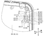
裏ケース21の裏側面102には一対の掛止孔31が設けられる。この一対の掛止孔31は、壁掛け式とするための孔である。一対の掛止孔31は、左側(図面では右側)の縁の近傍に設定される左側掛止孔311と、右側(図面では左側)の縁の近傍に設定される右側掛止孔312との2つで設定されている。ちなみに、左側掛止孔311と右側掛止孔312とは、バッテリチェッカ10を壁に掛けた際の左右バランスが良くなるように、ケース20の左右対称位置に設けられている。さらに、左側掛止孔311と右側掛止孔312とは、壁に掛けた際の上下バランスが良くなるように、ケース20の半分より上側の範囲に設けられている。   A pair of retaining holes 31 are provided on the back side surface 102 of the back case 21. The pair of retaining holes 31 are holes for wall mounting. The pair of latching holes 31 includes a left latching hole 311 set in the vicinity of the left (right side in the drawing) edge and a right latching hole 312 set in the vicinity of the right (left side in the drawing) edge. Two are set. Incidentally, the left retaining hole 311 and the right retaining hole 312 are provided at symmetrical positions of the case 20 so that the left / right balance is improved when the battery checker 10 is hung on the wall. Furthermore, the left side hooking hole 311 and the right side hooking hole 312 are provided in a range above the half of the case 20 so that the vertical balance when hung on the wall is improved.

これら左側掛止孔311と右側掛止孔312とは互いに同一の掛止孔31で構成される。このため、以下に掛止孔31を説明するにあたっては右側掛止孔312を例に挙げて説明することとする。なお、このケース20の裏側面102には、乾電池が収容される乾電池収容部23が設けられている。この乾電池収容部23は収容カバー24にて閉塞されている。収容カバー24は、係止フック251にて裏ケース21に係止されているとともに留め螺子252にて螺子止めされている。   The left side hooking hole 311 and the right side hooking hole 312 are constituted by the same hooking hole 31. For this reason, in the following description of the latching hole 31, the right latching hole 312 will be described as an example. In addition, the back side surface 102 of the case 20 is provided with a dry battery housing portion 23 in which a dry battery is housed. The dry battery housing part 23 is closed by a housing cover 24. The housing cover 24 is locked to the back case 21 by a locking hook 251 and is screwed by a retaining screw 252.

掛止孔31は、掛止構造30の一部をなす。図4はケース20の内部側から視た掛止構造30を示す斜視図である。図5は取付部40に蓋部材70を取り付けようとする掛止構造30を示す斜視図である。図6は蓋部材70が取り付けられていない取付部40を示す斜視図である。図7は別の角度から視た図6の取付部40を示す斜視図である。図8は蓋部材70が取り付けられていない取付部40を示す正面図である。図9は蓋部材70が取り付けられていない取付部40を示す左側面図である。図10は蓋部材70が取り付けられていない取付部40を示す上面図である。図11は外部から視た掛止孔31を示す正面図である。図12は蓋部材70の単品外部形状を示す斜視図である。図13は別の角度から視た蓋部材70の単品外部形状を示す斜視図である。図14は蓋部材70の単品内部形状を示す斜視図である。図15は蓋部材70の外部を示す正面図である。図16は蓋部材70を示す左側面図である。   The latching hole 31 forms a part of the latching structure 30. FIG. 4 is a perspective view showing the latching structure 30 as viewed from the inside of the case 20. FIG. 5 is a perspective view showing the latching structure 30 for attaching the lid member 70 to the attachment portion 40. FIG. 6 is a perspective view showing the attachment portion 40 to which the lid member 70 is not attached. FIG. 7 is a perspective view showing the mounting portion 40 of FIG. 6 viewed from another angle. FIG. 8 is a front view showing the attachment portion 40 to which the lid member 70 is not attached. FIG. 9 is a left side view showing the attachment portion 40 to which the lid member 70 is not attached. FIG. 10 is a top view showing the attachment portion 40 to which the lid member 70 is not attached. FIG. 11 is a front view showing the retaining hole 31 viewed from the outside. FIG. 12 is a perspective view showing a single external shape of the lid member 70. FIG. 13 is a perspective view showing a single external shape of the lid member 70 viewed from another angle. FIG. 14 is a perspective view showing the internal shape of the single member of the lid member 70. FIG. 15 is a front view showing the outside of the lid member 70. FIG. 16 is a left side view showing the lid member 70.

図17〜図27に関しては、上記した取付部40に蓋部材70が取り付けられた掛止構造30を図示している。すなわち、図17は取付部40に蓋部材70が取り付けられた掛止構造30を示す正面図である。図18は図17の掛止構造30を示す左側面図である。図19は図17の掛止構造30を示す上面図である。図20は図17の(XX)-(XX)線断面矢視図である。図21は図18の(XXI)-(XXI)線断面矢視図である。図22は図17の(XXII)-(XXII)線断面矢視図である。図23は図17の(XXIII)-(XXIII)線断面矢視図である。図24は雄螺子Sが差し込まれた掛止孔31を示す外部斜視図である。図25は図24の(XXV)-(XXV)線断面矢視図である。図26は雄螺子Sが掛止された掛止孔31を示す外部斜視図である。図27は図26の(XXVII)-(XXVII)線断面矢視図である。   17 to 27, the latching structure 30 in which the lid member 70 is attached to the attachment portion 40 described above is illustrated. That is, FIG. 17 is a front view showing the latching structure 30 in which the lid member 70 is attached to the attachment portion 40. 18 is a left side view showing the latching structure 30 of FIG. FIG. 19 is a top view showing the latching structure 30 of FIG. 20 is a cross-sectional view taken along line (XX)-(XX) in FIG. 21 is a cross-sectional view taken along line (XXI)-(XXI) in FIG. 22 is a cross-sectional view taken along line (XXII)-(XXII) in FIG. 23 is a cross-sectional view taken along line (XXIII)-(XXIII) in FIG. FIG. 24 is an external perspective view showing the retaining hole 31 into which the male screw S is inserted. 25 is a cross-sectional view taken along the line (XXV)-(XXV) in FIG. FIG. 26 is an external perspective view showing the latching hole 31 with the male screw S latched thereon. 27 is a cross-sectional view taken along line (XXVII)-(XXVII) in FIG.

掛止構造30は、裏ケース21に設けられる掛止孔31と、裏ケース21に設けられる取付部40と、この取付部40に取り付けられる蓋部材70とを有する。掛止孔31は裏ケース21の裏側面102を裏から表へ貫通するようにして形成されている。つまり、掛止孔31は、外部の雄螺子S(図25および図27を参照)をケース20の内部に差込可能にケース20の内外を連通している。掛止孔31からケース20の内部に差し込まれた雄螺子Sの螺子頭S2は、この掛止孔31に対して掛止可能となっている。なお、図24〜図27に参照される雄螺子Sは、本発明に係る外部の掛止部材に相当する。この雄螺子Sは、広く利用される雄螺子と同様、螺子部S1と螺子頭S2とを有して構成される。なお、螺子部S1は、壁に埋め込んで支持される本発明に係る脚部に相当する。また、螺子頭S2は、螺子部S1の外径より拡大した外径をなす本発明に係る掛止頭部に相当する。この雄螺子Sの掛止に関しては、後に図24〜図27を参照しながら説明する。掛止孔31は、図11に示すように、一般にダルマ孔とも称される連通孔である。掛止孔31は、径の長ささが相違する大小の2つの孔33,35を連ねるようにして形成される。   The latching structure 30 includes a latching hole 31 provided in the back case 21, an attachment part 40 provided in the back case 21, and a lid member 70 attached to the attachment part 40. The retaining hole 31 is formed so as to penetrate the back side surface 102 of the back case 21 from the back to the front. That is, the retaining hole 31 communicates the inside and outside of the case 20 so that an external male screw S (see FIGS. 25 and 27) can be inserted into the case 20. The screw head S <b> 2 of the male screw S inserted into the case 20 from the retaining hole 31 can be latched to the retaining hole 31. The male screw S referred to in FIGS. 24 to 27 corresponds to an external latch member according to the present invention. The male screw S has a screw portion S1 and a screw head S2 in the same manner as a widely used male screw. The screw portion S1 corresponds to a leg portion according to the present invention which is embedded and supported in a wall. Moreover, screw head S2 is corresponded to the latching head which concerns on this invention which makes the outer diameter expanded from the outer diameter of screw part S1. The latching of the male screw S will be described later with reference to FIGS. As shown in FIG. 11, the retaining hole 31 is a communication hole that is also generally referred to as a dharma hole. The retaining hole 31 is formed so as to connect two large and small holes 33 and 35 having different diameters.

掛止孔31は、図11に示すように、下側の大径孔33と上側の小径孔35とが連接孔37を介在させながら連ねるようにして形成される。大径孔33は、小径孔35の径の長さと比較して相対的に長い径の内周縁34の孔として形成されている。逆に言えば、小径孔35は、大径孔33の径の長さと比較して相対的に短い径の内周縁36の孔として形成されている。また、連接孔37は、小径孔35の径のまま下方に真っ直ぐ延ばされた内周縁38の孔として形成されている。なお、大径孔33は、本発明に係る第1孔部に相当する孔であり、その内周縁34の径は雄螺子Sの螺子頭S2が差込可能な径で設定されている。これに対し、小径孔35は、本発明に係る第2孔部に相当する孔であり、その内周縁36の径は雄螺子Sの螺子頭S2の抜けが規制される径で設定されている。なお、連接孔37の内周縁38の径は、小径孔35と同一の径である。このように設定された小径孔35と大径孔33とは、上下の関係で並べられ、これらの間に連接孔37を介在させて互いに連なって、掛止孔31をなしている。   As shown in FIG. 11, the retaining hole 31 is formed such that the lower large-diameter hole 33 and the upper small-diameter hole 35 are connected with the connecting hole 37 interposed therebetween. The large-diameter hole 33 is formed as a hole of the inner peripheral edge 34 having a relatively long diameter compared to the diameter of the small-diameter hole 35. In other words, the small-diameter hole 35 is formed as a hole of the inner peripheral edge 36 having a relatively short diameter as compared with the length of the large-diameter hole 33. Further, the connecting hole 37 is formed as a hole of an inner peripheral edge 38 that extends straight downward while maintaining the diameter of the small diameter hole 35. The large-diameter hole 33 is a hole corresponding to the first hole portion according to the present invention, and the diameter of the inner peripheral edge 34 is set so that the screw head S2 of the male screw S can be inserted. On the other hand, the small-diameter hole 35 is a hole corresponding to the second hole portion according to the present invention, and the diameter of the inner peripheral edge 36 is set to a diameter that restricts the removal of the screw head S2 of the male screw S. . The diameter of the inner peripheral edge 38 of the connecting hole 37 is the same as that of the small diameter hole 35. The small-diameter hole 35 and the large-diameter hole 33 set in this way are arranged in an up-and-down relationship, and a connecting hole 37 is interposed therebetween to form a latching hole 31.

掛止孔31の内面側となるケース20の内面201には、取付部40が設けられている。この取付部40には、蓋部材70が取り付けられる。この取付部40に取り付けられる蓋部材70は、掛止孔31の開口をケース20の内部側から閉じる。この蓋部材70は、雄螺子Sが差し込まれる掛止孔31をケース20の内側から閉じる部材として構成される。なお、取付部40に対する蓋部材70の取付け方向は、小径孔35から大径孔33に向かう上から下への方向に設定されている。つまり、蓋部材70の取付け方向は、ケース20の内面201が延在される上から下へ方向となっている。この取付け方向で蓋部材70をスライドさせることにより蓋部材70は取付部40に取り付けられる。取付部40は、掛止孔31の内面201側に設けられる構造である。この取付部40は、掛止孔31と同様、左側(図示符号311)および右側(図示符号312)の双方に、同一構造で設けられている。   A mounting portion 40 is provided on the inner surface 201 of the case 20 that is the inner surface side of the retaining hole 31. A lid member 70 is attached to the attachment portion 40. The lid member 70 attached to the attachment portion 40 closes the opening of the retaining hole 31 from the inside of the case 20. The lid member 70 is configured as a member that closes the retaining hole 31 into which the male screw S is inserted from the inside of the case 20. Note that the attachment direction of the lid member 70 with respect to the attachment portion 40 is set in the direction from the top to the bottom from the small diameter hole 35 toward the large diameter hole 33. That is, the attachment direction of the lid member 70 is from the top to the bottom where the inner surface 201 of the case 20 extends. The lid member 70 is attached to the attachment portion 40 by sliding the lid member 70 in this attachment direction. The attachment portion 40 has a structure provided on the inner surface 201 side of the retaining hole 31. The mounting portion 40 is provided with the same structure on both the left side (indicated by reference numeral 311) and the right side (indicated by reference numeral 312), like the retaining hole 31.

図4〜図11を参照にしながら、取付部40について説明する。なお、図6および図7以外の図面では取付部40の周囲の図示を省略している。取付部40は、概略、突出縁部41と、閉塞部50と、支持ガイド部55と、ストッパ部60とを有する。突出縁部41は、本発明に係る第1突出縁に相当する。突出縁部41は、掛止孔31の内周縁34,36,38に沿って設けられている。この突出縁部41は、この掛止孔31の内周縁34,36,38のそれぞれからケース20の内部に向かって突き出されるように形成されている。具体的には、大径孔33の内周縁34に沿って第1突出縁部44が設けられ、小径孔35の内周縁36に沿って第2突出縁部46が設けられ、連接孔37の内周縁38に沿って第3突出縁部48が設けられている。これら第1〜第3突出縁部44,46,48は、掛止孔31をなす内周縁34,36,38と同様、互いに連なってケース20の内部に向かって突き出されている。なお、第1突出縁部44の下側半分は、次に詳述する閉塞部50と連なるように形成されている。逆に言えば、第2,3突出縁部46,48と第1突出縁部44の上側半分とは、裏ケース21の板厚と同等の長さ分だけケース20の内部に向かって突き出されて形成されている。   The attachment part 40 will be described with reference to FIGS. In addition, illustration of the periphery of the attachment part 40 is abbreviate | omitted in drawings other than FIG. 6 and FIG. The attachment portion 40 generally includes a protruding edge portion 41, a closing portion 50, a support guide portion 55, and a stopper portion 60. The protruding edge portion 41 corresponds to the first protruding edge according to the present invention. The protruding edge 41 is provided along the inner peripheral edge 34, 36, 38 of the retaining hole 31. The protruding edge portion 41 is formed so as to protrude from the inner peripheral edges 34, 36, and 38 of the retaining hole 31 toward the inside of the case 20. Specifically, a first projecting edge portion 44 is provided along the inner peripheral edge 34 of the large diameter hole 33, and a second projecting edge portion 46 is provided along the inner peripheral edge 36 of the small diameter hole 35. A third protruding edge 48 is provided along the inner peripheral edge 38. These first to third projecting edge portions 44, 46, and 48 are connected to each other and protrude toward the inside of the case 20 in the same manner as the inner peripheral edges 34, 36, and 38 that form the retaining holes 31. The lower half of the first protruding edge 44 is formed so as to be continuous with the closing portion 50 described in detail below. In other words, the second and third protruding edges 46 and 48 and the upper half of the first protruding edge 44 protrude toward the inside of the case 20 by a length equivalent to the plate thickness of the back case 21. Is formed.

閉塞部50は、大径孔33の下側半分の突出縁部41を更にケース20の内部に向かって突き出すように形成される周壁部51と、この周壁部51と連なりながら大径孔33を覆うように大径孔33と対面配置される円形部52とを有する。言い換えれば、周壁部51は、大径孔33と対面配置される円形部52の下側半分と、大径孔33の内周縁34の下側半分とを連接する。また、この円形部52の上端から上方に支持ガイド部55が延びている。支持ガイド部55は、本発明に係る取付支持部に相当する。この支持ガイド部55は、掛止孔31と対面する位置まで下から上に延びている。この支持ガイド部55は、取り付けられた蓋部材70をケース20の内部の内側から掛止孔31に向けて支持する。具体的には、支持ガイド部55は、円形部52の上端から上方に延び、小径孔35および連接孔37に対面配置される。なお、円形部52は、図8および図11に示すように、大径孔33の開口形状よりも僅かに小さく形成され、支持ガイド部55も小径孔35および連接孔37の開口形状よりも僅かに小さく形成されている。   The blocking portion 50 includes a peripheral wall portion 51 formed so as to protrude the protruding half portion 41 of the lower half of the large diameter hole 33 further toward the inside of the case 20, and the large diameter hole 33 while being connected to the peripheral wall portion 51. A large-diameter hole 33 and a circular portion 52 arranged to face each other are provided so as to cover. In other words, the peripheral wall portion 51 connects the lower half of the circular portion 52 facing the large diameter hole 33 and the lower half of the inner peripheral edge 34 of the large diameter hole 33. Further, a support guide portion 55 extends upward from the upper end of the circular portion 52. The support guide portion 55 corresponds to an attachment support portion according to the present invention. The support guide portion 55 extends from the bottom up to a position facing the retaining hole 31. The support guide portion 55 supports the attached lid member 70 from the inside of the case 20 toward the retaining hole 31. Specifically, the support guide portion 55 extends upward from the upper end of the circular portion 52, and is disposed facing the small diameter hole 35 and the connection hole 37. 8 and 11, the circular portion 52 is formed slightly smaller than the opening shape of the large-diameter hole 33, and the support guide portion 55 is also slightly smaller than the opening shapes of the small-diameter hole 35 and the connecting hole 37. It is formed small.

これら円形部52と支持ガイド部55のケース20の内面201には、支持リブ56が設けられている。支持リブ56は、左右方向に延びる水平リブ57と、上下方向に延びる上下リブ58とを有する。水平リブ57は、閉塞部50の下側範囲に対して水平方向に延びるように設けられている。上下リブ58は、閉塞部50の上側範囲および支持ガイド部55に対して上下方向に延びるように設けられている。この支持ガイド部55は、閉塞部50および支持ガイド部55に対して適切な強度を加えている。なお、この支持リブ56(水平リブ57,上下リブ58)は、図9に示すように裏ケース21の板厚と同等の厚み分の長さに設定されている。また、水平リブ57は、図6および図7に示すように、裏ケース21の左右の側壁211,212から連なるサイドリブ29と連なっている。この水平リブ57の上側に向く面は、蓋部材70を取付部40に取り付けた際、蓋部材70の開口端78が当接する下側当接面59として機能する。   Support ribs 56 are provided on the inner surface 201 of the case 20 of the circular portion 52 and the support guide portion 55. The support rib 56 includes a horizontal rib 57 extending in the left-right direction and an upper and lower rib 58 extending in the up-down direction. The horizontal rib 57 is provided to extend in the horizontal direction with respect to the lower range of the closing portion 50. The upper and lower ribs 58 are provided so as to extend in the vertical direction with respect to the upper range of the closing portion 50 and the support guide portion 55. The support guide portion 55 adds appropriate strength to the closing portion 50 and the support guide portion 55. The support ribs 56 (the horizontal ribs 57 and the upper and lower ribs 58) are set to a length equivalent to the plate thickness of the back case 21, as shown in FIG. Further, as shown in FIGS. 6 and 7, the horizontal rib 57 is continuous with the side rib 29 that is continuous from the left and right side walls 211, 212 of the back case 21. The surface facing the upper side of the horizontal rib 57 functions as a lower contact surface 59 with which the opening end 78 of the cover member 70 contacts when the cover member 70 is attached to the attachment portion 40.

掛止孔31の上方にはストッパ部60が設けられている。ストッパ部60は、ケース20の内面201からケース20の内部に向かって突き出すように形成される。具体的には、ストッパ部60は、図8に示すように正面視矩形の形状であり、図9に示すように上から下に向かうにしたがってケース20の内部に徐々に突き出された形状に形成される。このストッパ部60は、本発明に係る外し規制部に相当し、取付部40に対する蓋部材70の外しを規制する。具体的には、ストッパ部60のうち、ケース20の内部側に向く面は、下側に向けてケース20の内部側に張り出されるテーパ面61として設定される。テーパ面61は、取付部40に蓋部材70を取り付ける際のガイド面として形成される。このように蓋部材70を取付部40に取り付ける際は、蓋部材70の上端735をテーパ面61にて乗り越えさせる。この際、支持ガイド部55は、ケース20の内部側(内側)に僅かに弾性変形する。このように蓋部材を内側から支持する支持ガイド部55は、取付部40に対する蓋部材70のストッパ部60を越えた取付けを許容することとなる。テーパ面61を乗り越えた蓋部材70は、ストッパ部60の下側に配置されて取付部40に取り付けられたものとなる。   A stopper portion 60 is provided above the retaining hole 31. The stopper 60 is formed so as to protrude from the inner surface 201 of the case 20 toward the inside of the case 20. Specifically, the stopper portion 60 has a rectangular shape when viewed from the front as shown in FIG. 8, and is formed so as to gradually protrude into the case 20 from the top to the bottom as shown in FIG. Is done. The stopper portion 60 corresponds to a removal restricting portion according to the present invention, and restricts the removal of the lid member 70 from the attachment portion 40. Specifically, the surface of the stopper portion 60 that faces the inner side of the case 20 is set as a tapered surface 61 that projects downward toward the inner side of the case 20. The tapered surface 61 is formed as a guide surface when the lid member 70 is attached to the attachment portion 40. In this way, when the lid member 70 is attached to the attachment portion 40, the upper end 735 of the lid member 70 is moved over the tapered surface 61. At this time, the support guide portion 55 is slightly elastically deformed toward the inner side (inner side) of the case 20. Thus, the support guide portion 55 that supports the lid member from the inside allows the attachment of the lid member 70 to the attachment portion 40 beyond the stopper portion 60. The lid member 70 that has passed over the tapered surface 61 is disposed on the lower side of the stopper portion 60 and attached to the attachment portion 40.

ストッパ部60のうち、ケース20の下側に向く面は、上記した下側当接面59と対面する上側当接面62として設定される。この上側当接面62は、突き出されたストッパ部60の段差により形成される。この上側当接面62は、蓋部材70を取付部40に取り付けた際、蓋部材70の外し方向への移動を規制する。この上側当接面62は、蓋部材70を上記した下側当接面59と共に挟み込むようにして、取付部40に対する蓋部材70の取付け状態を支持する。このため、下側当接面59と上側当接面62とは、互いにケース20の内面201と直交方向に延びる当接面で形成される。取付部40に取り付けられた蓋部材70が下から上へ移動しようとすると、ストッパ部60の上側当接面62に蓋部材70の当接面736が当たって蓋部材70のスライドが規制され、取付部40に対する蓋部材70の外れは規制される。   A surface of the stopper portion 60 that faces the lower side of the case 20 is set as an upper contact surface 62 that faces the lower contact surface 59 described above. The upper abutment surface 62 is formed by a stepped portion of the protruding stopper portion 60. The upper contact surface 62 restricts the movement of the lid member 70 in the removal direction when the lid member 70 is attached to the attachment portion 40. The upper contact surface 62 supports the attachment state of the lid member 70 to the attachment portion 40 so as to sandwich the lid member 70 together with the lower contact surface 59 described above. For this reason, the lower contact surface 59 and the upper contact surface 62 are formed as contact surfaces extending in a direction orthogonal to the inner surface 201 of the case 20. When the lid member 70 attached to the attachment portion 40 tries to move from the bottom to the top, the contact surface 736 of the lid member 70 hits the upper contact surface 62 of the stopper portion 60 and the sliding of the lid member 70 is restricted. The detachment of the lid member 70 with respect to the attachment portion 40 is restricted.

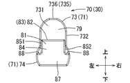
図12〜図20を参照にしながら、蓋部材70について説明する。蓋部材70は樹脂成形品である。蓋部71は、掛止孔31の開口形状に略一致する外周形状(正面視略ダルマ形)を有し、この掛止孔31の開口形状を閉じる蓋形をなしている。蓋部材70は、概略、蓋部71と差込ガイド部81とを有する。具体的には、蓋部71は、第1蓋部73と第2蓋部74とを上下で連接して形成される。第1蓋部73は、小径孔35および連接孔37の開口形状を蓋するように設けられる。この第1蓋部73は、小径孔35および連接孔37を覆うように対面配置される第1対面部731と、第1対面部731の外周に沿って周壁をなす第1周壁部732とを有する。第1対面部731は、小径孔35および連接孔37を覆う形状に形成され、これら小径孔35および連接孔37と対面している。また、第1周壁部732は、第1対面部731の周縁から側壁形に延ばされて形成されている。なお、この第1周壁部732の上端735は、ストッパ部60の上側当接面62が当接する当接面736として面形状に形成される。   The lid member 70 will be described with reference to FIGS. The lid member 70 is a resin molded product. The lid portion 71 has an outer peripheral shape (substantially dharma shape in front view) that substantially matches the opening shape of the retaining hole 31, and has a lid shape that closes the opening shape of the retaining hole 31. The lid member 70 generally includes a lid portion 71 and an insertion guide portion 81. Specifically, the lid portion 71 is formed by vertically connecting a first lid portion 73 and a second lid portion 74. The first lid 73 is provided so as to cover the opening shapes of the small diameter hole 35 and the connecting hole 37. The first lid portion 73 includes a first facing portion 731 that is disposed so as to cover the small-diameter hole 35 and the connecting hole 37, and a first peripheral wall portion 732 that forms a peripheral wall along the outer periphery of the first facing portion 731. Have. The first facing portion 731 is formed in a shape that covers the small diameter hole 35 and the connecting hole 37, and faces the small diameter hole 35 and the connecting hole 37. The first peripheral wall portion 732 is formed to extend from the peripheral edge of the first facing portion 731 into a side wall shape. The upper end 735 of the first peripheral wall portion 732 is formed in a surface shape as an abutment surface 736 with which the upper abutment surface 62 of the stopper portion 60 abuts.

これに対し、第2蓋部74は、大径孔33の上側半分の開口形状を蓋する。この第2蓋部74は、大径孔33の上側半分を覆うように対面配置される第2対面部741と、第2対面部741(図14参照)の外周に沿って周壁をなす第2周壁部742とを有する。第2対面部741は、大径孔33の上側半分を覆う形状に形成され、これら大径孔33の上側半分と対面している。また、第2周壁部742は、第2対面部741の周縁から側壁形に延ばされて形成されている。この蓋部材70は、取付部40に取り付けるにあたっての開口部75,77が設けられている。すなわち、蓋部材70には、掛止孔31との対面範囲に設けられる対面開口部75と、下部範囲に設けられる下部開口部77とが、設けられている。対面開口部75は、第1周壁部732および第2周壁部742の裏側に向いた端縁で設定されている。下部開口部77は、第2周壁部742の下側に向いた端縁で設定されている。なお、下部開口部77は、取付部40の突出縁部41および閉塞部50を収容可能な開口形状を有して形成される。この下部開口部77の下端は、上記した取付部40の下側当接面59と当接する蓋部材70の開口端78として設定される。   On the other hand, the second lid 74 covers the opening shape of the upper half of the large-diameter hole 33. This 2nd cover part 74 is the 2nd facing part 741 arrange | positioned facing so that the upper half of the large diameter hole 33 may be covered, and the 2nd which makes a surrounding wall along the outer periphery of the 2nd facing part 741 (refer FIG. 14). A peripheral wall portion 742. The second facing portion 741 is formed in a shape that covers the upper half of the large-diameter hole 33, and faces the upper half of the large-diameter hole 33. The second peripheral wall portion 742 is formed to extend from the peripheral edge of the second facing portion 741 into a side wall shape. The lid member 70 is provided with openings 75 and 77 for attachment to the attachment portion 40. That is, the lid member 70 is provided with a facing opening 75 provided in a facing range with the retaining hole 31 and a lower opening 77 provided in a lower range. The facing opening 75 is set at an edge facing the back side of the first peripheral wall 732 and the second peripheral wall 742. The lower opening 77 is set at an edge facing the lower side of the second peripheral wall 742. The lower opening 77 is formed to have an opening shape that can accommodate the protruding edge portion 41 and the closing portion 50 of the attachment portion 40. The lower end of the lower opening 77 is set as an opening end 78 of the lid member 70 that comes into contact with the lower contact surface 59 of the mounting portion 40 described above.

蓋部71の外周面79には、蓋部71と連なって差込ガイド部81が設けられている。この差込ガイド部81は、蓋部71の下側半分の範囲に対して対面するように設けられている。逆に言えば、差込ガイド部81と蓋部71とは内外2段で並列されるように連接して形成される。この差込ガイド部81は、取付部40の支持ガイド部55が差し込まれる差込孔82を有して形成される。つまり、差込部83は、支持ガイド部55を下から上に嵌め込む構造として設けられている。差込ガイド部81は、差込孔82が設定される差込部83と、取付部40の下部を覆う延在部87とを有する。差込部83は、蓋部71の外周面79と対面配置される対面壁84を有する。   An insertion guide portion 81 is provided on the outer peripheral surface 79 of the lid portion 71 so as to be continuous with the lid portion 71. The insertion guide portion 81 is provided so as to face the range of the lower half of the lid portion 71. In other words, the insertion guide portion 81 and the lid portion 71 are formed so as to be connected in parallel in two stages of the inside and outside. The insertion guide portion 81 is formed with an insertion hole 82 into which the support guide portion 55 of the attachment portion 40 is inserted. That is, the insertion part 83 is provided as a structure in which the support guide part 55 is fitted from the bottom to the top. The insertion guide portion 81 includes an insertion portion 83 in which the insertion hole 82 is set, and an extending portion 87 that covers the lower portion of the attachment portion 40. The insertion portion 83 has a facing wall 84 that is disposed to face the outer peripheral surface 79 of the lid portion 71.

対面壁84の左側および右側には、対面壁84と外周面79とを連接する左側壁851および右側壁852が設けられている。ここで、互いに対面する対面壁84と外周面79との間には、上下に延びる差込孔82が設けられている。この対面壁84の下側には、取付部40の下部を覆うように延びる延在部87が設けられている。この延在部87は、取付部40の円形部52を覆うまで下側に延びている。なお、差込部83の左右両側の外周部分には、一対の段差部88が設けられている。この段差部88は、突出縁部41との間の隙間を埋め、ケース20外部からケース20内部に装置される基板までの沿面距離を延ばしてケース20内外の密閉性を高めている。これによって、ケース20外部に対して、ケース20内部に装置される基板の電気的絶縁性能は高められることとなる。このように電気的絶縁性能が向上すると、例えばケース20外部からケース20内部に装置される基板への静電気の飛びを生じ難くして、装置の誤動作や回路故障を抑制することができる。   On the left and right sides of the facing wall 84, a left side wall 851 and a right side wall 852 that connect the facing wall 84 and the outer peripheral surface 79 are provided. Here, an insertion hole 82 extending vertically is provided between the facing wall 84 and the outer peripheral surface 79 facing each other. An extending portion 87 is provided below the facing wall 84 so as to cover the lower portion of the mounting portion 40. The extending portion 87 extends downward until the circular portion 52 of the mounting portion 40 is covered. A pair of stepped portions 88 are provided on the outer peripheral portions on both the left and right sides of the insertion portion 83. The stepped portion 88 fills the gap between the protruding edge portion 41 and extends the creeping distance from the outside of the case 20 to the substrate mounted inside the case 20 to enhance the sealing inside and outside the case 20. As a result, the electrical insulation performance of the substrate installed inside the case 20 is enhanced with respect to the outside of the case 20. When the electrical insulation performance is improved in this way, for example, it is difficult for static electricity to jump from the outside of the case 20 to the substrate mounted inside the case 20, and malfunction of the device and circuit failure can be suppressed.

取付部40に取り付けられた蓋部材70には、取付部40との間でオーバーラップする構造が設けられている。すなわち、蓋部材70の第1周壁部732および第2周壁部742は、取付部40に設けられる第1〜第3突出縁部44,46,48(突出縁部41)と板厚方向で重なる。なお、これらの第1〜第3突出縁部44,46,48は、上記したように掛止孔31の内周縁34,36,38に沿って設けられている。また、蓋部材70の開口端78は、取付部40に設けられる水平リブ57と板厚方向で重なる。つまり、取付部40に取り付けられた蓋部材70は、掛止孔31の周囲を板厚方向で重なるように形成されている。このように取付部40に取り付けられた蓋部材70の重なる構成は、掛止孔31の全周に亘るように設定されており、重なる長さとしてはケース20の略板厚の長さと一致するように設定されている。   The lid member 70 attached to the attachment portion 40 is provided with a structure that overlaps with the attachment portion 40. That is, the first peripheral wall portion 732 and the second peripheral wall portion 742 of the lid member 70 overlap with the first to third protruding edge portions 44, 46, and 48 (the protruding edge portion 41) provided in the attachment portion 40 in the plate thickness direction. . The first to third projecting edges 44, 46, and 48 are provided along the inner peripheral edges 34, 36, and 38 of the retaining hole 31 as described above. Further, the opening end 78 of the lid member 70 overlaps with the horizontal rib 57 provided in the attachment portion 40 in the plate thickness direction. That is, the lid member 70 attached to the attachment portion 40 is formed so as to overlap the periphery of the retaining hole 31 in the plate thickness direction. Thus, the overlapping structure of the lid member 70 attached to the attachment portion 40 is set so as to extend over the entire circumference of the retaining hole 31, and the overlapping length coincides with the length of the substantially plate thickness of the case 20. Is set to

上記した掛止孔31には、図24〜図27に示すように雄螺子Sが掛止される。具体的には、先ず雄螺子Sは、図24および図25に示すように、掛止孔31の大径孔33に差し込まれる。なお、図示される雄螺子Sは、螺子部S1を壁に捩じ込んで固定される、一般的な壁掛け用の雄螺子である。また、大径孔33は雄螺子Sの螺子頭S2を差し込むことができる内周縁34を有している。ここでバッテリチェッカ10を、雄螺子Sに対して下へスライドさせると、図26および図27に示すようになる。すなわち、雄螺子Sは、大径孔33から連接孔37を通過して小径孔35へと移動することとなる。ここで、小径孔35は、内周縁36の径は雄螺子Sの螺子頭S2の抜けが規制される径で設定されている。このため、掛止孔31には、雄螺子Sの螺子頭S2が掛止することとなる。   As shown in FIGS. 24 to 27, the male screw S is hooked on the hooking hole 31 described above. Specifically, first, the male screw S is inserted into the large-diameter hole 33 of the retaining hole 31 as shown in FIGS. The male screw S shown in the drawing is a general wall-hanging male screw that is fixed by screwing the screw portion S1 into a wall. The large-diameter hole 33 has an inner peripheral edge 34 into which the screw head S2 of the male screw S can be inserted. Here, when the battery checker 10 is slid downward with respect to the male screw S, it becomes as shown in FIGS. That is, the male screw S moves from the large diameter hole 33 through the connecting hole 37 to the small diameter hole 35. Here, in the small-diameter hole 35, the diameter of the inner peripheral edge 36 is set to a diameter that prevents the screw head S2 of the male screw S from coming off. For this reason, the screw head S <b> 2 of the male screw S is engaged with the engagement hole 31.

上記した実施の形態のバッテリチェッカ10によれば、次のような作用効果を奏することができる。すなわち上記したバッテリチェッカ10によれば、壁掛け用の雄螺子Sの螺子部S1を掛止孔31に差し込んでバッテリチェッカ10を壁に掛けておくことができる。これによって、壁掛け式のバッテリチェッカ10とすることができる。ここで、取付部40に取り付けられた蓋部材70は、掛止孔31の開口をケース20の内部側から閉じることができる。これによって、蓋部材70は、ケース20の外部からケース20の内部に掛止孔31を通じて異物や静電気の侵入してくるのを防いで、この異物や静電気が侵入することによる製品の誤作動を防止することができる。   According to the battery checker 10 of the above-described embodiment, the following operational effects can be achieved. That is, according to the battery checker 10 described above, the battery checker 10 can be hung on the wall by inserting the screw portion S1 of the male screw S for wall hanging into the retaining hole 31. Thus, the wall-mounted battery checker 10 can be obtained. Here, the lid member 70 attached to the attachment portion 40 can close the opening of the latching hole 31 from the inside of the case 20. As a result, the lid member 70 prevents foreign matter and static electricity from entering the case 20 from the outside of the case 20 through the retaining holes 31, and malfunctions of the product due to the foreign matter and static electricity intruding. Can be prevented.

また、上記したバッテリチェッカ10によれば、支持ガイド部55は掛止孔31と対面する位置に設けられて蓋部材70を内側から掛止孔31に向けて支持する。これによって、異物が掛止孔31を通じて蓋部材70を押すようなことがあっても、蓋部材70は支持ガイド部55にて支持されて外れ難くなる。したがって、外部からの異物の侵入にも蓋部材70は強固に支持されることとなり、製品の誤作動を強力に防止することができる。また、上記したバッテリチェッカ10によれば、取付部40に対する蓋部材70の取付け方向はケース20の内面201に沿った内面201の延在方向に設定されているので、支持ガイド部55の存在が邪魔にならずに蓋部材70を取付部40に取り付けることができる。これによって、取付部40に対する蓋部材70の取付けを簡単かつ確実に行うことができる。   Further, according to the battery checker 10 described above, the support guide portion 55 is provided at a position facing the latching hole 31 and supports the lid member 70 from the inside toward the latching hole 31. As a result, even if a foreign object pushes the lid member 70 through the retaining hole 31, the lid member 70 is supported by the support guide portion 55 and is difficult to come off. Therefore, the lid member 70 is firmly supported even when foreign matter enters from the outside, and the malfunction of the product can be strongly prevented. Further, according to the battery checker 10 described above, the attachment direction of the lid member 70 with respect to the attachment portion 40 is set in the extending direction of the inner surface 201 along the inner surface 201 of the case 20, so that the support guide portion 55 exists. The lid member 70 can be attached to the attachment portion 40 without obstruction. Thereby, the lid member 70 can be easily and reliably attached to the attachment portion 40.

また、上記したバッテリチェッカ10によれば、蓋部材70には支持ガイド部55を嵌め込む構造が設けられているので、支持ガイド部55による蓋部材70の支持を高めることができる。これによって、取付部40に対する蓋部材70の取付けをより確実にすることができる。また、上記したバッテリチェッカ10によれば、ストッパ部60により取付部40に対する蓋部材70の外しを規制することができる。これによって、取付部40に対する蓋部材70の取付け状態を強固に保持することができる。なお、このように設けられるストッパ部60は、支持ガイド部55の弾性変形によって支持ガイド部55に干渉されることなく蓋部材70の取付けを行うことができるので、蓋部材70の取付けも容易に行うことができる。   Further, according to the battery checker 10 described above, since the cover member 70 is provided with a structure in which the support guide portion 55 is fitted, the support of the cover member 70 by the support guide portion 55 can be enhanced. Thereby, the attachment of the lid member 70 to the attachment portion 40 can be made more reliable. Further, according to the battery checker 10 described above, the stopper member 60 can restrict the removal of the lid member 70 from the attachment portion 40. Thereby, the attachment state of the lid member 70 with respect to the attachment part 40 can be firmly held. In addition, since the stopper part 60 provided in this way can attach the cover member 70 without interfering with the support guide part 55 by the elastic deformation of the support guide part 55, the attachment of the cover member 70 is also easy. It can be carried out.

また、上記したバッテリチェッカ10によれば、取付部40に対する蓋部材70の取付け方向は上から下に向けた方向であるので、蓋部材70に対しての重力作用は蓋部材70の取付け方向と一致することとなる。これによって、蓋部材70の外れを抑えることができる。また、蓋部材70の第1周壁部732および第2周壁部742は、取付部40に設けられる第1〜第3突出縁部44,46,48(突出縁部41)と板厚方向で重なるので、掛止孔31の開口の縁部分をオーバーラップさせて閉じることができる。これによって、掛止孔31からケース20の内部への閉塞沿面距離を延ばして密閉性を高めている。したがって、掛止孔31からのケース20の内部への異物や静電気の侵入をより抑えることができる。なお、上記したバッテリチェッカ10によれば、壁掛け用の雄螺子Sを掛止孔31に差し込んで、バッテリチェッカ10を壁に掛けておくことができる。これによって、一般的な雄螺子を掛止部材として利用して、壁掛け式のバッテリチェッカ10とすることができる。   Further, according to the battery checker 10 described above, the mounting direction of the lid member 70 with respect to the mounting portion 40 is a direction from the top to the bottom, so that the gravity action on the lid member 70 is the same as the mounting direction of the lid member 70. Will match. Thereby, the detachment of the lid member 70 can be suppressed. Further, the first peripheral wall portion 732 and the second peripheral wall portion 742 of the lid member 70 overlap with the first to third protruding edge portions 44, 46, and 48 (the protruding edge portion 41) provided in the attachment portion 40 in the plate thickness direction. Therefore, the edge part of the opening of the retaining hole 31 can be overlapped and closed. Thereby, the closing creepage distance from the retaining hole 31 to the inside of the case 20 is extended to improve the sealing performance. Therefore, foreign matter and static electricity can be further prevented from entering the case 20 from the retaining hole 31. According to the battery checker 10 described above, the battery checker 10 can be hung on the wall by inserting the male screw S for hanging on the wall into the retaining hole 31. Thus, a wall-hanging battery checker 10 can be obtained by using a general male screw as a locking member.

なお、本発明に係るバッテリ装着器にあっては、上記した実施の形態に限定されるものではなく適宜に変更を加えて構成することが可能である。例えば、上記した実施の形態では、バッテリ装着器の一例としてバッテリチェッカ10を挙げ、これを説明するものとした。しかしながら、本発明に係るバッテリ装着器は、例えば電動工具用バッテリを充電する充電器として構成されるものであってもよく、電動工具用バッテリが着脱される構成であれば適宜の構成に対して採用することができる。また、本発明に係る蓋部材としては、掛止孔の開口をケースの内部側から閉じるようにケースの内面に設定される取付部に取り付けられる構成であれば、適宜の構成を採用することができる。具体的には、蓋部材70の掛止孔31の開口をケース20の内部側から閉じる構成としては、上記した蓋部71の構成に限定されることなく適宜の形状を選択することができる。また、蓋部材70の取付け方向に関しては、掛止孔31に対して左右方向で蓋部材70を取り付けるように構成したり、掛止孔31に対して対面方向で蓋部材70を取り付けるように構成したりするものであってもよい。また、本発明に係る取付部にあっても、例えばストッパ部60を無くして構成してもよいし、このような外し規制部として機能を左右方向で適宜に設けるようにしてもよい。   In addition, in the battery mounting device which concerns on this invention, it is not limited to above-described embodiment, It is possible to add and change suitably. For example, in the above-described embodiment, the battery checker 10 is given as an example of the battery mounter, and this will be described. However, the battery mounting device according to the present invention may be configured, for example, as a charger that charges a power tool battery. Can be adopted. In addition, as the lid member according to the present invention, an appropriate configuration may be adopted as long as the lid member is configured to be attached to an attachment portion set on the inner surface of the case so as to close the opening of the latching hole from the inner side of the case. it can. Specifically, the configuration of closing the opening of the latching hole 31 of the lid member 70 from the inside of the case 20 is not limited to the configuration of the lid portion 71 described above, and an appropriate shape can be selected. Further, with respect to the mounting direction of the lid member 70, the lid member 70 is configured to be attached to the latch hole 31 in the left-right direction, or the lid member 70 is configured to be opposed to the latch hole 31. It may be a thing to do. Moreover, even if it exists in the attachment part which concerns on this invention, you may comprise without the stopper part 60, for example, and you may make it provide a function suitably in the left-right direction as such a removal control part.

バッテリ装着器は、搬送式であって、使用者が誤って落下させるおそれがある。落下した際には、例えばバッテリ装着器の表示出力部(液晶表示パネル)等が破損するおそれがある。そのため液晶表示パネルが破損し難いバッテリ装着器が従来必要とされている。そこでバッテリ装着器は、上記構成に代えてあるいは加えて下記の構成Aを有していても良い。   The battery mounter is of a transport type and may be accidentally dropped by the user. When dropped, for example, the display output unit (liquid crystal display panel) of the battery mounter may be damaged. For this reason, there has been a need for a battery mounter that is unlikely to damage the liquid crystal display panel. Therefore, the battery mounter may have the following configuration A instead of or in addition to the above configuration.

バッテリ装着器には、上述するように電動工具用バッテリが着脱される。バッテリ装着器は、構成Aとして例えば、電動工具用バッテリの状態を表示するための液晶表示パネルと、液晶表示パネルの裏面を保持するLCD用ケースと、液晶表示パネルの表面を覆いかつ透明性を有する材料から形成されかつLCD用ケースに装着されるLCD用カバーと、LCD用カバーを開口する開口窓が形成されたケースを有する。そしてケース内においてLCDカバーがケースに取り付けられずにLCDケースがケースに取り付けられている。   As described above, the power tool battery is attached to and detached from the battery mounting device. The battery mounter has, for example, a liquid crystal display panel for displaying the state of the battery for the power tool, an LCD case for holding the back surface of the liquid crystal display panel, and a liquid crystal display panel that covers the surface and is transparent. The LCD cover is formed of a material having the same structure and attached to the LCD case, and the case has an opening window for opening the LCD cover. The LCD case is attached to the case without the LCD cover being attached to the case.

したがって液晶表示パネルが外力を受け難い構成になっている。例えばケースが力を受けて歪んだ場合、その歪みは、ケースからLCD用ケースを経て液晶表示パネルに伝わる。そのため液晶表示パネルへの力がLCD用ケースによって緩和された後に液晶表示パネルに伝わる。かくして液晶表示パネルへ伝わる力が小さくなって、液晶表示パネルが破損することが抑制される。LCD用カバーが力を受ける場合がある。その力は、LCD用カバーからLCD用ケースを経て液晶表示パネルに伝わる。そのため液晶表示パネルへの力がLCD用ケースによって緩和された後に液晶表示パネルに伝わる。かくして液晶表示パネルへ伝わる力が小さくなって、液晶表示パネルが破損することが抑制される。   Therefore, the liquid crystal display panel is configured not to receive external force. For example, when the case is distorted by force, the distortion is transmitted from the case to the liquid crystal display panel through the LCD case. Therefore, the force applied to the liquid crystal display panel is transmitted to the liquid crystal display panel after being relaxed by the LCD case. Thus, the force transmitted to the liquid crystal display panel is reduced, and the liquid crystal display panel is prevented from being damaged. The LCD cover may receive force. The force is transmitted from the LCD cover to the liquid crystal display panel through the LCD case. Therefore, the force applied to the liquid crystal display panel is transmitted to the liquid crystal display panel after being relaxed by the LCD case. Thus, the force transmitted to the liquid crystal display panel is reduced, and the liquid crystal display panel is prevented from being damaged.

前記構成Aを有するバッテリ装着器において、LCD用ケースとLCD用カバーの両部材の1つが、他の1つに形成された掛止め部に掛けられる爪を有していても良い。したがって爪は、LCD用ケースとLCD用カバーを合理的に接続する。例えばLCD用カバーがLCD用ケースよりも表に位置する。そのためLCD用カバーが受けた力は、LCD用ケースに向かい、LCD用ケースによって受け止められ得る。そのためLCD用カバーとLCD用ケースは、外れない程度の比較的小さな力で接続しても良い。したがって爪という比較的簡易な構造によってLCD用ケースとLCD用カバーを接続することができる。   In the battery mounting device having the configuration A, one of the members of the LCD case and the LCD cover may have a claw that is hooked on a latching portion formed on the other one. Accordingly, the claw rationally connects the LCD case and the LCD cover. For example, the LCD cover is located on the front side of the LCD case. Therefore, the force received by the LCD cover is directed to the LCD case and can be received by the LCD case. For this reason, the LCD cover and the LCD case may be connected with a relatively small force that does not come off. Therefore, the LCD case and the LCD cover can be connected by a relatively simple structure called a claw.

上記構成Aを有するバッテリ装着器において、LCD用カバーは、中心部が周囲部よりも表側に膨らむ曲面を有していても良い。したがってLCD用カバーは、比較的外力に対して破損し難い。例えばLCD用カバーの中心部に外力が加わった場合、その力が曲面によって外周へ分散され、広い範囲で外力が受け止められ得る。   In the battery mounter having the configuration A, the LCD cover may have a curved surface whose center portion swells more to the front side than the surrounding portion. Therefore, the LCD cover is relatively difficult to be damaged by an external force. For example, when an external force is applied to the center of the LCD cover, the force is distributed to the outer periphery by the curved surface, and the external force can be received in a wide range.

上記構成Aを有するバッテリ装着器において、ケースは、開口窓の周りに沿って形成されかつLCD用カバーよりも外方に突出する突状部を有していても良い。したがって突状部がLCD用カバーよりも先に外力を受け易い。これによりLCD用カバーが受ける外力が小さくなり、LCD用カバーの破損等が抑制され得る。   In the battery mounting device having the configuration A, the case may have a protruding portion that is formed around the opening window and protrudes outward from the LCD cover. Therefore, the protrusion is liable to receive an external force before the LCD cover. Thereby, the external force received by the LCD cover is reduced, and damage to the LCD cover can be suppressed.

上記構成Aを有するバッテリ装着器において、バッテリ装着器が操作ボタンとコントローラとケーブルを有していても良い。操作ボタンは、液晶表示パネルの画面を切替えるために操作され、かつ液晶表示パネルの一縁の近傍に位置するようにケースに設けられる。コントローラは、ケースに設けられかつ液晶表示パネルに信号を発する。ケーブルは、液晶表示パネルの前記一縁の反対側の他縁から延出して液晶表示パネルとコントローラを接続する。   In the battery mounting device having the configuration A, the battery mounting device may include an operation button, a controller, and a cable. The operation button is operated to switch the screen of the liquid crystal display panel, and is provided on the case so as to be positioned near one edge of the liquid crystal display panel. The controller is provided in the case and emits a signal to the liquid crystal display panel. The cable extends from the other edge opposite to the one edge of the liquid crystal display panel and connects the liquid crystal display panel and the controller.

したがって液晶表示パネルと操作ボタンの間にケーブルが配されない。そのため操作ボタンが液晶表示パネルに近接して設けられ、操作ボタンを液晶表示パネルの表示画面に合わせて操作し易くなる。一方、ケーブルは、液晶表示パネルと操作ボタンの間の狭い空間に影響を受けることなく設けられる。そのためケーブルは、比較的広い空間において液晶表示パネルとコントローラを接続できる。   Therefore, no cable is arranged between the liquid crystal display panel and the operation buttons. For this reason, the operation buttons are provided close to the liquid crystal display panel, and the operation buttons are easily operated in accordance with the display screen of the liquid crystal display panel. On the other hand, the cable is provided without being affected by a narrow space between the liquid crystal display panel and the operation buttons. Therefore, the cable can connect the liquid crystal display panel and the controller in a relatively wide space.

上記構成Aを有するバッテリ装着器において、ケースは、裏ケースと、裏ケースに装着されかつ開口窓が形成された表ケースを有する。表ケースにLCD用ケースが装着されても良い。これにより表ケースの開口窓に対してLCD用ケースおよび液晶表示パネルを正確かつ容易に位置合わせすることができる。   In the battery mounter having the configuration A, the case includes a back case and a front case that is attached to the back case and has an opening window. An LCD case may be attached to the front case. Thus, the LCD case and the liquid crystal display panel can be accurately and easily aligned with the opening window of the front case.

上記構成Aを有するバッテリ装着器において、ケースは、裏ケースと、裏ケースに装着されかつ開口窓が形成された表ケースを有する。裏ケースに液晶表示パネルに信号を発するコントローラと、液晶表示パネルが装着されたLCD用ケースが設けられても良い。したがって液晶表示パネルとコントローラがともに裏ケースに装着される。これにより表ケースを裏ケースに装着する前において液晶表示パネルとコントローラを電気的に接続することができる。   In the battery mounter having the configuration A, the case includes a back case and a front case that is attached to the back case and has an opening window. A controller that emits a signal to the liquid crystal display panel and an LCD case on which the liquid crystal display panel is mounted may be provided on the back case. Therefore, both the liquid crystal display panel and the controller are mounted on the back case. Thus, the liquid crystal display panel and the controller can be electrically connected before the front case is attached to the back case.

図面を用いて上述の構成を下記に詳しく説明する。図1に示すようにバッテリチェッカ10は、バッテリ装着器の1例であって、ケース20と表示出力部17を有する。ケース20は、裏ケース21と裏ケース21に装着される表ケース27を備え、ケース20内に表示出力部17が設けられる。   The above configuration will be described in detail below with reference to the drawings. As shown in FIG. 1, the battery checker 10 is an example of a battery mounter and includes a case 20 and a display output unit 17. The case 20 includes a back case 21 and a front case 27 attached to the back case 21, and the display output unit 17 is provided in the case 20.

図28に示すように表示出力部17は、液晶表示パネル(LCDパネル)1とLCD用ケース2とLCD用カバー3を有する。液晶表示パネル1は、矩形板状であって、バッテリチェッカ10で診断した電動工具バッテリBの診断結果等を表示する。LCD用ケース2は、皿状であって、液晶表示パネル1を保持する本体板2aを有する。液晶表示パネル1の裏面が接着剤等によって本体板2aの表面に接合または装着される。   As shown in FIG. 28, the display output unit 17 includes a liquid crystal display panel (LCD panel) 1, an LCD case 2, and an LCD cover 3. The liquid crystal display panel 1 has a rectangular plate shape and displays a diagnosis result of the electric tool battery B diagnosed by the battery checker 10. The LCD case 2 is dish-shaped and has a main body plate 2 a that holds the liquid crystal display panel 1. The back surface of the liquid crystal display panel 1 is bonded or attached to the surface of the main body plate 2a with an adhesive or the like.

図28,図29に示すようにLCD用ケース2は、本体板2aの外周に沿う壁部2bを有する。壁部2bは、液晶表示パネル1の厚みよりも高く、液晶表示パネル1の外周を保護する。壁部2bは、本体板2aの上縁に切欠き2fを有し、ケーブル4が挿通される。ケーブル4は、例えばフラットケーブルであって、液晶表示パネル1の上縁から切欠き2fを通って延出し、図33に示す回路基板6に接続される。   As shown in FIGS. 28 and 29, the LCD case 2 has a wall portion 2b along the outer periphery of the main body plate 2a. The wall 2b is higher than the thickness of the liquid crystal display panel 1 and protects the outer periphery of the liquid crystal display panel 1. The wall 2b has a notch 2f on the upper edge of the main body plate 2a, and the cable 4 is inserted therethrough. The cable 4 is, for example, a flat cable, extends from the upper edge of the liquid crystal display panel 1 through the notch 2f, and is connected to the circuit board 6 shown in FIG.

図28,図29に示すようにLCD用ケース2にはLCD用カバー3が装着される。LCD用ケース2は、壁部2bから外方に突出する掛け止部2cを有する。掛け止部2cは、例えば壁部2bの上縁左部と上縁右部から上方へ突出する掛け止部2cと、壁部2bの下縁中央部から下方へ突出する掛け止部2cを有する。各掛け止部2cには、LCD用カバー3の爪3eが挿通される貫通孔が形成される。   As shown in FIGS. 28 and 29, an LCD cover 3 is attached to the LCD case 2. The LCD case 2 has a latching portion 2c that protrudes outward from the wall portion 2b. The latching portion 2c has, for example, a latching portion 2c that protrudes upward from the left and upper edges of the wall 2b, and a latching portion 2c that projects downward from the center of the lower edge of the wall 2b. . Each latching portion 2c is formed with a through-hole through which the claw 3e of the LCD cover 3 is inserted.

図28,図29に示すようにLCD用ケース2は、ケース20に装着される。LCD用ケース2は、壁部2bから外方に突出する複数の装着部2d,2eを有する。装着部2dは、本体板2aの上左領域と上右領域の裏面から上方に延出する。装着部2eは、壁部2bの下左部と下右部から下方へ突出する。各装着部2d,2eにねじ5の脚が挿通される貫通孔を有する。ねじ5の脚が表ケース27の裏面から裏側へ突出するボス27eに螺合され、ねじ5の頭が装着部2d,2eを保持する。これによりLCD用ケース2が図30に示すようにねじ5によって表ケース27に装着される。   As shown in FIGS. 28 and 29, the LCD case 2 is attached to the case 20. The LCD case 2 has a plurality of mounting portions 2d and 2e protruding outward from the wall portion 2b. The mounting portion 2d extends upward from the back surface of the upper left region and the upper right region of the main body plate 2a. The mounting part 2e protrudes downward from the lower left part and the lower right part of the wall part 2b. Each mounting part 2d, 2e has a through-hole through which the leg of the screw 5 is inserted. The leg of the screw 5 is screwed into a boss 27e protruding from the back side of the front case 27 to the back side, and the head of the screw 5 holds the mounting portions 2d and 2e. As a result, the LCD case 2 is attached to the front case 27 by the screws 5 as shown in FIG.

図28,図29に示すようにLCD用カバー3は、矩形板状であって、透明性の高い樹脂から形成される。LCD用カバー3は、開口窓27aによって開口される本体部3cと、本体部3cの外周に沿うフランジ部3aと、LCD用カバー3をLCD用ケース2に装着するための爪3eを有する。本体部3cは、図31に示すように開口窓27a内に装着され、表ケース27の表側面101に沿う形状である。したがってLCD用カバー3は、美観に優れている。本体部3cは、表ケース27の表側面101よりもやや内側に位置する。したがって本体部3cが外力を受け難く、LCD用カバー3が破損し難い。   As shown in FIGS. 28 and 29, the LCD cover 3 has a rectangular plate shape and is made of a highly transparent resin. The LCD cover 3 includes a main body 3c opened by the opening window 27a, a flange 3a along the outer periphery of the main body 3c, and a claw 3e for mounting the LCD cover 3 on the LCD case 2. As shown in FIG. 31, the main body portion 3 c is mounted in the opening window 27 a and has a shape along the front side surface 101 of the front case 27. Therefore, the LCD cover 3 is excellent in aesthetics. The main body 3 c is located slightly inside the front side surface 101 of the front case 27. Therefore, the main body 3c is hardly subjected to external force, and the LCD cover 3 is not easily damaged.

図31を参照するようにLCD用カバー3の本体部3cの表面は、表ケース27の表側面101に沿う形状であるとともに、中央部が上部と下部よりも表側に膨らむ曲面を有する。したがって本体部3cが力を受けた場合、その力は曲面によって上下方向へ分散される。図28に示すように表ケース27は、開口窓27aの外周に沿って表側へ突出する突状部27bを有する。したがって突状部27bは、LCD用カバー3よりも先に外力を受けることでLCD用カバー3に外力が加わることを軽減させ得る。   As shown in FIG. 31, the surface of the main body portion 3c of the LCD cover 3 has a shape along the front side surface 101 of the front case 27, and has a curved surface in which the central portion swells to the front side from the upper and lower portions. Therefore, when the main body 3c receives a force, the force is dispersed in the vertical direction by the curved surface. As shown in FIG. 28, the front case 27 has a protruding portion 27b that protrudes to the front side along the outer periphery of the opening window 27a. Therefore, the protrusion 27 b can reduce the external force applied to the LCD cover 3 by receiving the external force before the LCD cover 3.

図28,図29に示すようにLCD用カバー3のフランジ部3aは、本体部3cよりも裏側に位置し、本体部3cに沿って環状である。フランジ部3aの表面には、本体部3cの外周縁に隣接する位置決め突部3dが形成される。突部3dは、表ケース27の裏面に開口窓27aに沿って形成された凹部27gに設置される。突部3dの表面が凹部27gの底面に当接または隣接されることで、LCD用カバー3と表ケース27の表裏方向の位置を決定する。突部3dの外周端が凹部27gの周壁に当接または隣接されることで、LCD用カバー3の表ケース27に対する上下方向および左右方向の位置を決定する。   As shown in FIGS. 28 and 29, the flange portion 3a of the LCD cover 3 is located on the back side of the main body portion 3c and is annular along the main body portion 3c. A positioning projection 3d adjacent to the outer peripheral edge of the main body 3c is formed on the surface of the flange 3a. The protrusion 3d is installed in a recess 27g formed on the back surface of the front case 27 along the opening window 27a. The front and back positions of the LCD cover 3 and the front case 27 are determined by the surface of the protrusion 3d being in contact with or adjacent to the bottom surface of the recess 27g. When the outer peripheral end of the protrusion 3d is in contact with or adjacent to the peripheral wall of the recess 27g, the vertical and horizontal positions of the LCD cover 3 with respect to the front case 27 are determined.

図28,図29に示すようにLCD用カバー3は、LCD用ケース2に取り付くための複数の爪3eを有する。爪3eは、それぞれLCD用カバー3の上縁左部と上縁右部と下縁中央部から裏側へ延出する。各爪3eは、外方へ突出する先端部を有する。爪3eは、LCD用ケース2の掛け止部2cに表側から裏側へ挿入される際に弾性変形し、弾性戻りすることで先端部が掛け止部2cに掛かる。爪3eは、LCD用カバー3がLCD用ケース2に対して表側へ外れることを防止する。また爪3eは、上下方向に弾性変形可能であて、LCD用カバー3をLCD用ケース2に対して上下方向に弾性的に保持する。一方、爪3eは、左右方向に弾性変形し難く、LCD用カバー3をLCD用ケース2に対して左右方向に移動する量を規制する。   As shown in FIGS. 28 and 29, the LCD cover 3 has a plurality of claws 3 e for attaching to the LCD case 2. The claws 3e extend from the upper edge left part, upper edge right part, and lower edge center part of the LCD cover 3 to the back side. Each claw 3e has a tip portion protruding outward. The claw 3e is elastically deformed when inserted into the latching portion 2c of the LCD case 2 from the front side to the backside, and the tip portion is hooked on the latching portion 2c by elastically returning. The claw 3 e prevents the LCD cover 3 from coming off to the front side with respect to the LCD case 2. The claw 3e is elastically deformable in the vertical direction, and elastically holds the LCD cover 3 in the vertical direction with respect to the LCD case 2. On the other hand, the claw 3e is hardly elastically deformed in the left-right direction, and restricts the amount of movement of the LCD cover 3 with respect to the LCD case 2 in the left-right direction.

図28,図29を参照するようにLCD用カバー3のフランジ部3aの裏面は、LCD用ケース2の壁部2bの表端に当接する。したがってLCD用ケース2がLCD用カバー3を裏側から支持する。そのためLCD用カバー3が表側から外力を受けた場合、LCD用カバー3がLCD用ケース2の壁部2bによって裏側から支持される。   As shown in FIGS. 28 and 29, the back surface of the flange portion 3 a of the LCD cover 3 abuts on the front end of the wall portion 2 b of the LCD case 2. Therefore, the LCD case 2 supports the LCD cover 3 from the back side. Therefore, when the LCD cover 3 receives an external force from the front side, the LCD cover 3 is supported from the back side by the wall portion 2 b of the LCD case 2.

図33に示すように回路基板6は、基板本体6aとコントローラ6bと放電回路6cを有する。コントローラ6bは、例えばマイクロコントロールユニット(MCU)であって、バッテリチェッカ10に装着された図2に示すバッテリBと通信可能に連結される。コントローラ6bは、バッテリBから発信された通信信号に基づいてバッテリBの状態を診断するプログラム(ファームウェア)、アルゴリズム等を記憶するフラッシュメモリを有する。放電回路6cは、バッテリBと接続され、バッテリBを放電させる。コントローラ6bは、放電時におけるバッテリBの放電容量を測定することでバッテリBを診断することも可能である。   As shown in FIG. 33, the circuit board 6 includes a board body 6a, a controller 6b, and a discharge circuit 6c. The controller 6b is, for example, a micro control unit (MCU), and is connected to a battery B shown in FIG. The controller 6b has a flash memory that stores a program (firmware), an algorithm, and the like for diagnosing the state of the battery B based on a communication signal transmitted from the battery B. The discharge circuit 6c is connected to the battery B and discharges the battery B. The controller 6b can also diagnose the battery B by measuring the discharge capacity of the battery B at the time of discharging.

図33,図36に示すように基板本体6aにコネクタ6dが装着され、コネクタ6dにマイクロUSB等のケーブルが接続される。ケーブルによって回路基板6とコンピュータ(PC)が接続され、コントローラ6bがコンピュータにバッテリBの診断結果等を信号として発信する。コンピュータは、バッテリBの診断結果を受信して、表示等をすることができる。また、ケーブルによって、回路基板6とプリンタを接続してもよい。このプリンタで、バッテリBの診断結果等を印刷してもよい。   As shown in FIGS. 33 and 36, a connector 6d is attached to the substrate body 6a, and a cable such as a micro USB is connected to the connector 6d. The circuit board 6 and the computer (PC) are connected by a cable, and the controller 6b transmits a diagnosis result of the battery B as a signal to the computer. The computer can receive and display the diagnosis result of the battery B. Further, the circuit board 6 and the printer may be connected by a cable. With this printer, the diagnosis result of the battery B may be printed.

図33,図36に示すように基板本体6aにカードリーダー6eが装着され、カードリーダー6eにSDカード等のメモリカードが挿入される。カードリーダー6eによってメモリカードとコントローラ6bが通信可能に接続される。したがってメモリカードに記憶された情報に基づいてコントローラ6bに記憶されたプログラム(ファームウェア)がアップデートされ得る。あるいはコントローラ6bに記憶されているバッテリBの診断結果等がメモリカードに送信されて記録され得る。バッテリBの診断結果等を記録したメモリカードをコンピュータに接続し、コンピュータでバッテリBの診断結果等を読み取り、ディスプレイで表示したり、プリントアウトすることも可能である。   As shown in FIGS. 33 and 36, a card reader 6e is attached to the substrate body 6a, and a memory card such as an SD card is inserted into the card reader 6e. The memory card and the controller 6b are communicably connected by the card reader 6e. Therefore, the program (firmware) stored in the controller 6b can be updated based on the information stored in the memory card. Or the diagnostic result of the battery B etc. which are memorize | stored in the controller 6b can be transmitted to a memory card and recorded. It is also possible to connect a memory card recording the diagnosis result of the battery B to the computer, read the diagnosis result of the battery B by the computer, and display it on the display or print it out.

図34,図35に示すようにケース20には、コネクタ6dとカードリーダー6eを開口する開口部20a,20bが形成される。ケース20には、開口部20a,20bを覆うための蓋7a,7bが着脱可能に取り付けられる。   As shown in FIGS. 34 and 35, the case 20 is formed with openings 20a and 20b for opening the connector 6d and the card reader 6e. Lids 7a and 7b for covering the openings 20a and 20b are detachably attached to the case 20.

図36に示すようにコントローラ6bは、液晶表示パネル1と図28に示すケーブル4を経由して通信可能に接続される。液晶表示パネル1は、コントローラ6bから発信された信号を受信して、バッテリBの診断結果等を表示する。   As shown in FIG. 36, the controller 6b is communicably connected to the liquid crystal display panel 1 via the cable 4 shown in FIG. The liquid crystal display panel 1 receives the signal transmitted from the controller 6b and displays the diagnosis result of the battery B and the like.

図33,図36に示すように基板本体6aには、操作部(操作ボタン)18と電源ボタン19が取り付けられる。操作部18は、押しボタンである戻しスイッチSW1と、押しボタンである送りスイッチSW2を有する。送りスイッチSW2は、押されることで信号をコントローラ6bに発信し、コントローラ6bは、液晶表示パネル1の表示画面を次の画面となるように液晶表示パネル1に表示信号を発信する。戻しスイッチSW1は、押されることで信号をコントローラ6bに発信し、コントローラ6bは、液晶表示パネル1の表示画面が前の表示画面になるように液晶表示パネル1に表示信号を発信する。電源ボタン19は、押しボタンであって、押されることで信号をコントローラ6bに発信する。コントローラ6bは、電源ボタン19からの信号に基づいて駆動用乾電池からの電力をコントローラ6bと液晶表示パネル1へ供給するON状態と遮断するOFF状態に切替える。   As shown in FIGS. 33 and 36, an operation unit (operation button) 18 and a power button 19 are attached to the substrate body 6a. The operation unit 18 includes a return switch SW1 that is a push button and a feed switch SW2 that is a push button. When the feed switch SW2 is pressed, a signal is transmitted to the controller 6b, and the controller 6b transmits a display signal to the liquid crystal display panel 1 so that the display screen of the liquid crystal display panel 1 becomes the next screen. When the return switch SW1 is pressed, a signal is transmitted to the controller 6b, and the controller 6b transmits a display signal to the liquid crystal display panel 1 so that the display screen of the liquid crystal display panel 1 becomes the previous display screen. The power button 19 is a push button and sends a signal to the controller 6b when pressed. Based on a signal from the power button 19, the controller 6 b switches between an ON state in which power from the driving dry battery is supplied to the controller 6 b and the liquid crystal display panel 1 and an OFF state in which the power is cut off.

図31,図32に示すように操作部18と電源ボタン19は、脚部18a,19aと頭部18c,19cを有する。脚部18a,19aの先端に回路基板6と電気的に接続されるスイッチ機構18b,19bを有し、操作部18と電源ボタン19の操作がスイッチ機構18b,19bによって電気信号に変換される。   As shown in FIGS. 31 and 32, the operation unit 18 and the power button 19 have leg portions 18a and 19a and head portions 18c and 19c. Switch mechanisms 18b and 19b electrically connected to the circuit board 6 are provided at the tips of the leg portions 18a and 19a, and operations of the operation unit 18 and the power button 19 are converted into electrical signals by the switch mechanisms 18b and 19b.

図31,図32に示すように操作部18と電源ボタン19の頭部18c,19cは、表ケース27の表側面101に沿う形状であり、かつ表側面101よりもやや奥側に位置する。したがって操作部18と電源ボタン19が誤って操作されることが抑制される。操作部18の頭部18cの表面は、他の操作部18に近い部分から遠くなるほど裏側に傾斜する。さらに操作部18の頭部18cの表面は、上部から下方に向けて裏側に傾斜する。電源ボタン19の頭部19cは、中央部分が外周部分よりも表側に位置する曲面形状を有する。   As shown in FIGS. 31 and 32, the operation unit 18 and the heads 18 c and 19 c of the power button 19 are shaped along the front side surface 101 of the front case 27, and are located slightly behind the front side surface 101. Accordingly, it is possible to prevent the operation unit 18 and the power button 19 from being erroneously operated. The surface of the head 18 c of the operation unit 18 is inclined to the back side as the distance from the part close to the other operation unit 18 increases. Furthermore, the surface of the head 18c of the operation unit 18 is inclined backward from the top to the bottom. The head portion 19c of the power button 19 has a curved shape in which the central portion is located on the front side of the outer peripheral portion.

図29,図31に示すように表ケース27は、裏面から突出するボス27fを有し、ボス27fが裏ケース21に当接される。裏ケース21の裏側からねじが挿入されて、ねじの先端がボス27fに螺合される。これにより裏ケース21に表ケース27が取り付けられる。   As shown in FIGS. 29 and 31, the front case 27 has a boss 27 f protruding from the back surface, and the boss 27 f is in contact with the back case 21. A screw is inserted from the back side of the back case 21, and the tip of the screw is screwed into the boss 27f. As a result, the front case 27 is attached to the back case 21.

LCD用ケース2は、図28,図29に示す本体板2aに代えて、液晶表示パネル1を裏から支持する他の構造、例えば網状、外周部分のみを有する環状であっても良い。LCD用ケース2とLCD用カバー3は、上述するようにLCD用ケース2に形成された掛け止部2cと、LCD用カバー3に形成された爪3eによって装着される。これに代えて、LCD用ケース2とLCD用カバー3は、LCD用ケース2に形成された爪と、LCD用カバー3に形成された掛け止部によって装着されても良い。あるいは、LCD用ケース2とLCD用カバー3は、ねじ等の他の取付構造によって装着されても良い。   The LCD case 2 may have another structure that supports the liquid crystal display panel 1 from the back, for example, a net-like shape or an annular shape having only an outer peripheral portion, instead of the main body plate 2a shown in FIGS. The LCD case 2 and the LCD cover 3 are attached by the latching portion 2c formed on the LCD case 2 and the claws 3e formed on the LCD cover 3 as described above. Instead of this, the LCD case 2 and the LCD cover 3 may be mounted by claws formed on the LCD case 2 and a latching portion formed on the LCD cover 3. Alternatively, the LCD case 2 and the LCD cover 3 may be mounted by other mounting structures such as screws.

上述する液晶表示パネル1は、バッテリチェッカ10によって診断されたバッテリBの診断結果を表示する。これに代えて、電動工具用バッテリがバッテリチェッカ10とは異なる装置に装着され、液晶表示パネル1が、前記装置に装着されたバッテリBの状態、例えば充電状態等をコントローラから受信して表示しても良い。   The liquid crystal display panel 1 described above displays the diagnosis result of the battery B diagnosed by the battery checker 10. Instead, the battery for the electric tool is mounted on a device different from the battery checker 10, and the liquid crystal display panel 1 receives and displays the state of the battery B mounted on the device, for example, the charging state from the controller. May be.

1 液晶表示パネル
2 LCD用ケース
3 LCD用カバー
3e 爪
4 ケーブル
6 回路基板
6b コントローラ
6c 放電回路
6d コネクタ
6e カードリーダー
10 バッテリチェッカ(バッテリ装着器)
101 表側面
102 裏側面
11 バッテリ装着部
12 スライドレール
13 フック部
14 接続端子部
15 端子カバー
17 表示出力部
18 操作部(操作ボタン)
19 電源ボタン
20 ケース
201 内面
21 裏ケース(下側ケース)
211,212 側壁
23 乾電池収容部
24 収容カバー
251 係止フック
252 螺子
27 表ケース(上側ケース)
27a 開口窓
28 雄螺子
29 サイドリブ
30 掛止構造
31 掛止孔
311 左側掛止孔
312 右側掛止孔
33 大径孔(第1孔部)
34 内周縁
35 小径孔(第2孔部)
36 内周縁
37 連接孔
38 内周縁
40 取付部
41 突出縁部(縁部)
44 第1突出縁部
46 第2突出縁部
48 第3突出縁部
50 閉塞部
51 周壁部
52 円形部
55 支持ガイド部(取付支持部)
56 支持リブ
57 水平リブ
58 上下リブ
59 下側当接面
60 ストッパ部(外し規制部)
61 テーパ面
62 上側当接面
70 蓋部材
71 蓋部
73 第1蓋部
731 第1対面部
732 第1周壁部(壁部)
735 上端
736 当接面
74 第2蓋部
741 第2対面部
742 第2周壁部
75 対面開口部
77 下部開口部
78 開口端
79 外周面
81 差込ガイド部
82 差込孔
83 差込部(嵌め込む構造)
84 対面壁
851 左側壁
852 右側壁
87 延在部
88 段差部
B 電動工具用バッテリ
S 雄螺子(掛止部材)
S1 螺子部
S2 螺子頭
DESCRIPTION OF SYMBOLS 1 Liquid crystal display panel 2 LCD case 3 LCD cover 3e Claw 4 Cable 6 Circuit board 6b Controller 6c Discharge circuit 6d Connector 6e Card reader 10 Battery checker (battery mounting device)
DESCRIPTION OF SYMBOLS 101 Front side surface 102 Back side surface 11 Battery mounting part 12 Slide rail 13 Hook part 14 Connection terminal part 15 Terminal cover 17 Display output part 18 Operation part (operation button)
19 Power button 20 Case 201 Inner surface 21 Back case (lower case)
211, 212 Side wall 23 Dry cell storage portion 24 Storage cover 251 Locking hook 252 Screw 27 Front case (upper case)
27a Opening window 28 Male screw 29 Side rib 30 Latching structure 31 Latching hole 311 Left latching hole 312 Right latching hole 33 Large-diameter hole (first hole)
34 Inner peripheral edge 35 Small-diameter hole (second hole)
36 inner peripheral edge 37 connecting hole 38 inner peripheral edge 40 mounting portion 41 protruding edge (edge)
44 1st protrusion edge part 46 2nd protrusion edge part 48 3rd protrusion edge part 50 Closure part 51 Peripheral wall part 52 Circular part 55 Support guide part (attachment support part)
56 Support ribs 57 Horizontal ribs 58 Upper and lower ribs 59 Lower contact surface 60 Stopper part (removal restricting part)
61 Tapered surface 62 Upper contact surface 70 Lid member 71 Lid portion 73 First lid portion 731 First facing portion 732 First peripheral wall portion (wall portion)
735 Upper end 736 Abutting surface 74 Second lid portion 741 Second facing portion 742 Second peripheral wall portion 75 Opening portion 77 Lower opening portion 78 Opening end 79 Outer peripheral surface 81 Insertion guide portion 82 Insertion hole 83 Insertion portion (fit) Structure)
84 Face-to-face wall 851 Left side wall 852 Right side wall 87 Extension part 88 Step part B Battery S for electric tools S Male screw (holding member)
S1 Screw part S2 Screw head

Claims (8)

電動工具用バッテリが着脱されるバッテリ装着器であって、
外装としてのケースを有し、
前記ケースには、該ケースの内外を連通して外部の掛止部材を掛止可能とする掛止孔が設けられており、
前記掛止孔の開口を前記ケースの内部側から閉じる蓋部材が、前記ケースの内面に設定される取付部に取り付けられている、バッテリ装着器。
A battery mounter to which a battery for an electric tool is attached and detached,
Has a case as an exterior,
The case is provided with a hooking hole that allows the outer hooking member to be hooked by communicating the inside and outside of the case.
A battery mounting device, wherein a lid member that closes the opening of the retaining hole from the inside of the case is attached to an attachment portion set on the inner surface of the case.
請求項1に記載のバッテリ装着器において、
前記取付部は、前記掛止孔と対面する位置まで延びる取付支持部を有し、
前記取付支持部は、取り付けられた前記蓋部材を内側から前記掛止孔に向けて支持する、バッテリ装着器。
The battery mounter according to claim 1,
The attachment part has an attachment support part extending to a position facing the hooking hole,
The attachment support portion is a battery mounter that supports the attached lid member from the inside toward the retaining hole.
請求項2に記載のバッテリ装着器において、
前記取付部に対する前記蓋部材の取付け方向は、前記ケースの内面に沿った内面延在方向に設定されている、バッテリ装着器。
The battery mounter according to claim 2, wherein
The battery mounting device, wherein an attachment direction of the lid member with respect to the attachment portion is set to an inner surface extending direction along an inner surface of the case.
請求項3に記載のバッテリ装着器において、
前記蓋部材には、前記取付支持部を嵌め込む構造が設けられている、バッテリ装着器。
The battery mounter according to claim 3,
The battery mounting device, wherein the lid member is provided with a structure for fitting the attachment support portion.
請求項3または請求項4に記載のバッテリ装着器において、
前記取付部は、該取付部に対する前記蓋部材の外しを規制する外し規制部を有し、
前記取付支持部は、弾性変形することにより前記外し規制部を越えて前記取付部に対する前記蓋部材の取付けを許容する、バッテリ装着器。
In the battery mounting device according to claim 3 or 4,
The attachment portion has a removal restricting portion that restricts removal of the lid member with respect to the attachment portion,
The mounting support portion is a battery mounting device that allows the mounting of the lid member to the mounting portion beyond the removal restricting portion by elastic deformation.
請求項1から請求項5のいずれか1つに記載のバッテリ装着器において、
前記取付部に対する前記蓋部材の取付け方向は、上から下に向けた方向である、バッテリ装着器。
The battery mounting device according to any one of claims 1 to 5,
The battery mounting device, wherein an attachment direction of the lid member with respect to the attachment portion is a direction from top to bottom.
請求項1から請求項6のいずれか1つに記載のバッテリ装着器において、
前記蓋部材には、前記取付部に設けられる縁部と板厚方向で重なる壁部が設けられている、バッテリ装着器。
In the battery mounting device according to any one of claims 1 to 6,
The battery mounting device, wherein the lid member is provided with a wall portion that overlaps an edge portion provided in the attachment portion in a plate thickness direction.
請求項1から請求項7のいずれか1つに記載のバッテリ装着器において、
前記掛止部材は、壁に埋め込んで支持される脚部と、該脚部の外径より拡大した外径の掛止頭部と、を有し、
前記掛止孔は、前記掛止頭部が差込可能とされる第1孔部と、差し込まれた前記掛止頭部の抜けが規制されるように前記第1孔部よりも短い内径の第2孔部とが、下と上との関係で連ねられて形成されている、バッテリ装着器。
The battery mounting device according to any one of claims 1 to 7,
The latch member includes a leg portion embedded and supported in a wall, and a latch head portion having an outer diameter larger than the outer diameter of the leg portion,
The hooking hole has a first hole part into which the hooking head can be inserted, and an inner diameter shorter than the first hole part so as to prevent the hooked head from coming off. The battery mounting device, wherein the second hole portion is formed so as to be connected in a relationship of lower and upper.
JP2016071244A 2015-12-01 2016-03-31 Battery mounter Active JP6713318B2 (en)

Priority Applications (3)

Application Number Priority Date Filing Date Title
US15/356,782 US10461380B2 (en) 2015-12-01 2016-11-21 Battery attachment apparatuses
CN201611060707.7A CN107068923B (en) 2015-12-01 2016-11-25 Battery mounting device
EP16200809.8A EP3176904B1 (en) 2015-12-01 2016-11-25 Battery attachment apparatuses

Applications Claiming Priority (2)

Application Number Priority Date Filing Date Title
JP2015234447 2015-12-01

Publications (2)

Publication Number Publication Date
JP2017107829A true JP2017107829A (en) 2017-06-15
JP6713318B2 JP6713318B2 (en) 2020-06-24

Family

ID=59059897

Family Applications (1)

Application Number Title Priority Date Filing Date
JP2016071244A Active JP6713318B2 (en) 2015-12-01 2016-03-31 Battery mounter

Country Status (2)

Country Link
JP (1) JP6713318B2 (en)
CN (1) CN107068923B (en)

Families Citing this family (3)

* Cited by examiner, † Cited by third party
Publication number Priority date Publication date Assignee Title
CN111102283A (en) * 2018-10-25 2020-05-05 镫顺实业股份有限公司 Suction cup
CN111434935B (en) * 2019-01-15 2021-11-30 镫顺实业股份有限公司 Suction cup
CN112473155A (en) * 2020-10-30 2021-03-12 深圳市优必选科技股份有限公司 Connecting hole separating structure and building block

Citations (11)

* Cited by examiner, † Cited by third party
Publication number Priority date Publication date Assignee Title
JPH044446U (en) * 1990-04-23 1992-01-16
JPH09257013A (en) * 1996-03-22 1997-09-30 Oki Electric Ind Co Ltd Wall hanging structure for box body
JP2000061868A (en) * 1998-08-13 2000-02-29 Black & Decker Inc Cordless power tool system
JP2004147360A (en) * 2002-10-21 2004-05-20 Makita Corp Charger
JP2009296724A (en) * 2008-06-03 2009-12-17 Makita Corp Charger
JP2010182471A (en) * 2009-02-04 2010-08-19 Yazaki Corp Connector
JP2011082009A (en) * 2009-10-07 2011-04-21 Makita Corp Cap and tool equipped with the cap
JP2012043684A (en) * 2010-08-20 2012-03-01 Sanyo Electric Co Ltd Battery pack
JP2013042103A (en) * 2011-07-21 2013-02-28 Funai Electric Co Ltd Electrical apparatus and television apparatus
WO2013190955A1 (en) * 2012-06-20 2013-12-27 株式会社マキタ Charger
JP2014154465A (en) * 2013-02-13 2014-08-25 Hitachi Koki Co Ltd Electrical equipment and electrical device

Family Cites Families (1)

* Cited by examiner, † Cited by third party
Publication number Priority date Publication date Assignee Title
JP2015185395A (en) * 2014-03-25 2015-10-22 キヤノン株式会社 Electronic equipment

Patent Citations (11)

* Cited by examiner, † Cited by third party
Publication number Priority date Publication date Assignee Title
JPH044446U (en) * 1990-04-23 1992-01-16
JPH09257013A (en) * 1996-03-22 1997-09-30 Oki Electric Ind Co Ltd Wall hanging structure for box body
JP2000061868A (en) * 1998-08-13 2000-02-29 Black & Decker Inc Cordless power tool system
JP2004147360A (en) * 2002-10-21 2004-05-20 Makita Corp Charger
JP2009296724A (en) * 2008-06-03 2009-12-17 Makita Corp Charger
JP2010182471A (en) * 2009-02-04 2010-08-19 Yazaki Corp Connector
JP2011082009A (en) * 2009-10-07 2011-04-21 Makita Corp Cap and tool equipped with the cap
JP2012043684A (en) * 2010-08-20 2012-03-01 Sanyo Electric Co Ltd Battery pack
JP2013042103A (en) * 2011-07-21 2013-02-28 Funai Electric Co Ltd Electrical apparatus and television apparatus
WO2013190955A1 (en) * 2012-06-20 2013-12-27 株式会社マキタ Charger
JP2014154465A (en) * 2013-02-13 2014-08-25 Hitachi Koki Co Ltd Electrical equipment and electrical device

Also Published As

Publication number Publication date
JP6713318B2 (en) 2020-06-24
CN107068923A (en) 2017-08-18
CN107068923B (en) 2020-12-18

Similar Documents

Publication Publication Date Title
US8917515B2 (en) Electronic device having waterproof and shockproof functions
JP6602214B2 (en) Push switch
CN101123143B (en) Latch-release actuating apparatus
JP2017107829A (en) Battery attachment apparatus
CN107864579B (en) Waterproof cap and electronic equipment
TW201524033A (en) Electrical connector apparatus for connecting wiring board
US7887344B2 (en) Electronic device with an external connector
US9466440B2 (en) Switch device with erroneous operation preventer and the erroneous operation preventer
JP2014229746A (en) Electronic control unit and protective case
CN102315037B (en) Push switch
JP2013138091A (en) Electronic equipment
JP5377694B2 (en) Electronics
US20100024304A1 (en) Battery cover latch mechanism and portable electronic device using same
EP3176904B1 (en) Battery attachment apparatuses
JP5244055B2 (en) Control board storage case for gaming machines
JP2012182965A (en) Upper cover fitting detection structure of electric connection box
JP4815797B2 (en) Photodetector
JP4631507B2 (en) Emergency call button device
JP3186684U (en) Portable remote control device
JP2013106195A (en) Portable terminal
JP5432230B2 (en) Loosening prevention device and data storage device assembly using the same
US6743992B1 (en) Retaining device for sensor
JP4968171B2 (en) Electronic equipment housing structure
JP5637520B1 (en) Shield member coupling structure for gaming machines
JP2006210054A (en) Connector assembly and electronic equipment

Legal Events

Date Code Title Description
A621 Written request for application examination

Free format text: JAPANESE INTERMEDIATE CODE: A621

Effective date: 20181218

A977 Report on retrieval

Free format text: JAPANESE INTERMEDIATE CODE: A971007

Effective date: 20191209

A131 Notification of reasons for refusal

Free format text: JAPANESE INTERMEDIATE CODE: A131

Effective date: 20191224

A521 Request for written amendment filed

Free format text: JAPANESE INTERMEDIATE CODE: A523

Effective date: 20200203

TRDD Decision of grant or rejection written
A01 Written decision to grant a patent or to grant a registration (utility model)

Free format text: JAPANESE INTERMEDIATE CODE: A01

Effective date: 20200526

A61 First payment of annual fees (during grant procedure)

Free format text: JAPANESE INTERMEDIATE CODE: A61

Effective date: 20200603

R150 Certificate of patent or registration of utility model

Ref document number: 6713318

Country of ref document: JP

Free format text: JAPANESE INTERMEDIATE CODE: R150

R250 Receipt of annual fees

Free format text: JAPANESE INTERMEDIATE CODE: R250