JP2017106932A - Image measuring program, image measuring machine, and image measuring method - Google Patents
Image measuring program, image measuring machine, and image measuring method Download PDFInfo
- Publication number
- JP2017106932A JP2017106932A JP2017045072A JP2017045072A JP2017106932A JP 2017106932 A JP2017106932 A JP 2017106932A JP 2017045072 A JP2017045072 A JP 2017045072A JP 2017045072 A JP2017045072 A JP 2017045072A JP 2017106932 A JP2017106932 A JP 2017106932A
- Authority
- JP
- Japan
- Prior art keywords
- image
- touch panel
- measurement
- point
- user
- Prior art date
- Legal status (The legal status is an assumption and is not a legal conclusion. Google has not performed a legal analysis and makes no representation as to the accuracy of the status listed.)
- Pending
Links
Images
Landscapes
- Length Measuring Devices By Optical Means (AREA)
- User Interface Of Digital Computer (AREA)
Abstract
Description
本発明は、画像により試料の2点間の距離や特定範囲の面積等を測定するために用いる画像測定用プログラム、画像測定機、及び画像測定方法に関する。 The present invention relates to an image measurement program, an image measuring machine, and an image measuring method used for measuring a distance between two points of a sample, an area of a specific range, and the like by using an image.
従来、画像により試料の任意の2点間の距離や特定範囲の面積等を測定する画像測定機において、測定の基準点となる測定点を使用者が指定する操作のためにタッチパネルを用いたものが提案されている(例えば、特許文献1参照)。これによれば、使用者が画像上の任意の点を直感的に指定することができ、画像測定機の操作に熟達していない者でも容易に画像測定機を使用することが出来る。 Conventionally, in an image measuring machine that measures the distance between any two points of a sample or the area of a specific range by using an image, a touch panel is used for the user to specify the measurement point that is the measurement reference point Has been proposed (see, for example, Patent Document 1). According to this, the user can specify an arbitrary point on the image intuitively, and even an unskilled person in operation of the image measuring machine can easily use the image measuring machine.
しかしながら、ペンや指による入力ではタッチパネルに接触する面積が大きいため、画像表示部に表示されている画像の特定のピクセル位置を入力することが困難であり、使用者が意図する通りの正確な測定を行うのが困難であるという問題がある。 However, since the area touching the touch panel is large when inputting with a pen or finger, it is difficult to input a specific pixel position of the image displayed on the image display unit, and accurate measurement as intended by the user is performed. There is a problem that it is difficult to do.
このような問題に鑑みて、本発明は、タッチパネルを用いて正確な測定を可能とする画像測定用プログラム、画像測定機、及び画像測定方法を提供することを目的とする。 In view of such a problem, an object of the present invention is to provide an image measurement program, an image measurement machine, and an image measurement method that enable accurate measurement using a touch panel.
上記課題を解決するために本発明では、コンピュータに、
使用者が画像測定の基準点となる測定点を指定する前に試料画像の拡大表示のためのタッチパネルの操作を行うことを可能とし、これによって該タッチパネルから出力されたデータに基づいて、前記使用者が前記操作によって指定した点を中心として拡大した前記試料画像を含む画像データを前記タッチパネルへ出力する画像出力機能と、
前記使用者が前記測定点が未指定の拡大した前記試料画像を見ながら行う前記タッチパネルの操作によって前記測定点が未指定の拡大した前記試料画像に対して前記測定点を指定することを可能とし、これによって該タッチパネルから出力された前記測定点の指定に対応するデータに基づいて、前記測定点を確定する測定点確定機能と、
前記測定点を用いて前記画像測定を行う画像測定機能と、
前記画像測定機能によって測定された結果を出力する結果出力機能と、
を実現させることを特徴とする画像測定用プログラムを提供する。
In order to solve the above problems, in the present invention, the computer includes:
It is possible to operate the touch panel for the enlarged display of the sample image before the user designates the measurement point that becomes the reference point of the image measurement, and based on the data output from the touch panel, the use An image output function for outputting image data including the sample image enlarged around the point designated by the operation by the person to the touch panel;
The user can designate the measurement point for the enlarged sample image with the measurement point not designated by operating the touch panel while viewing the enlarged sample image with the measurement point not designated. The measurement point confirmation function for confirming the measurement point based on the data corresponding to the designation of the measurement point output from the touch panel thereby,
An image measurement function for performing the image measurement using the measurement points;
A result output function for outputting a result measured by the image measurement function;
An image measurement program characterized by realizing the above is provided.
また、上記課題を解決するために本発明では、コンピュータが備える画像出力機能が、使用者が画像測定の基準点となる測定点を指定する前に試料画像の拡大表示のためのタッチパネルの操作を行うことを可能とし、これによって該タッチパネルから出力されたデータに基づいて、前記使用者が前記操作によって指定した点を中心として拡大した前記試料画像を含む画像データを前記タッチパネルへ出力するステップと、
コンピュータが備える測定点確定機能が、前記使用者が前記測定点が未指定の拡大した前記試料画像を見ながら行う前記タッチパネルの操作によって前記測定点が未指定の拡大した前記試料画像に対して前記測定点を指定することを可能とし、これによって前記タッチパネルから出力された前記測定点の指定に対応するデータに基づいて、前記測定点を確定するステップと、
コンピュータが備える画像測定機能が、前記測定点を用いて前記画像測定を行うステップと、
コンピュータが備える結果出力機能が、前記画像測定機能によって測定された結果を出力するステップと、
を実行することを特徴とする画像測定方法を提供する。
In order to solve the above problems, in the present invention, the image output function provided in the computer operates the touch panel for enlarging the sample image before the user designates the measurement point as the reference point of the image measurement. Enabling to perform, and based on the data output from the touch panel, outputting to the touch panel image data including the sample image enlarged around the point designated by the user by the operation;
The measurement point determination function provided in the computer is configured to perform the operation on the touch panel performed by the user while viewing the enlarged sample image in which the measurement point is not specified. Making it possible to designate a measurement point, thereby determining the measurement point based on data corresponding to the designation of the measurement point output from the touch panel;
An image measurement function provided in the computer performs the image measurement using the measurement points;
A result output function provided in the computer outputs the result measured by the image measurement function;
An image measuring method is provided.
本発明によれば、タッチパネルを用いて正確な測定を可能とする画像測定用プログラム及び画像測定機を提供することができる。 According to the present invention, it is possible to provide an image measurement program and an image measuring machine that enable accurate measurement using a touch panel.
(第1実施形態)
以下、本願の第1実施形態に係る画像測定機について説明する。
(First embodiment)
The image measuring machine according to the first embodiment of the present application will be described below.
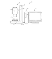
図1は第1実施形態に係る画像測定機1の概略構成図である。画像測定機1は、情報処理装置2と、試料観察装置3と、タッチパネル4とから構成されており、各構成要素は、シリアル接続やパラレル接続などの有線、又は、電波や赤外線などを用いた無線により接続されている。この他、情報処理装置2には、マウス、キーボード、プリンター、外付けハードディスク等が接続されていても良い。
FIG. 1 is a schematic configuration diagram of an
情報処理装置2は、後述する記憶装置11、中央処理装置12、インターフェース13(試料観察装置3及びタッチパネル4等との接続部分)を備え、試料観察装置3及びタッチパネル4の制御や、制御に必要なプログラムの保存、画像の保存等を行う。
The information processing device 2 includes a storage device 11, a central processing device 12, and an interface 13 (connection portion with the
試料観察装置3は、撮像装置6と、撮像装置6をテーブル等に支持する電動スタンド5とを備え、画像測定する試料を撮像して画像データを情報処理装置2へ出力する。
The
電動スタンド5は、スタンド台7と、スタンド台7の上部に装備された試料を載せるための電動ステージ8と、スタンド台7から垂直方向で上方へ延びる撮像装置支柱9とから構成されている。撮像装置支柱9は、ステージ8側の面から水平方向にステージ8側へ延び、撮像装置支柱9に沿って上下方向に平行移動することができる電動アーム10を備えている。電動ステージ8及び電動アーム10は情報処理装置2に有線又は無線により接続されており、情報処理装置2によって制御される。電動ステージ8としては、水平方向に試料を移動させることができるスライディングステージや、水平方向に対して傾斜をつけることで試料を斜め方向から観察できるようにするティルティングステージ等を用いることができる。なお、試料を動かすのが適当でない場合等においては、撮像装置6を水平方向に動かしたり、撮像装置6の角度を変化させるように動かしたりする構成とすることもできる。
The
撮像装置6は、アーム10に固定されており、撮像装置6は情報処理装置2と有線又は無線により接続され、情報処理装置2により制御されており、撮像装置6で撮像した画像データは、情報処理装置2へ出力され、情報処理装置2において記憶、編集等の処理がなされる。
The
タッチパネル4は、情報処理装置2と有線又は無線により接続されており、情報処理装置2から出力された画像データに基づいて画像を表示し、使用者が指先などによりパネル表面に接触することにより入力した指示を情報処理装置2へ出力する。タッチパネルとしては、抵抗膜方式、表面弾性波方式、赤外線方式、電磁誘導方式、静電容量方式等の動作原理に基づくものを用いる事が出来る。タッチパネル4を押下するものとしては、タッチパネル4の種類に応じて、使用者の指、通常のペン、電磁誘導ペン等の専用のタッチペン等を用いることができる。
The
なお、図1において情報処理装置2、試料観察装置3、タッチパネル4は、別体として構成されているが、これらの構成要素のうちいずれか2つを一体的に構成することも可能であり、また、全てを一体的に構成することも可能である。さらに、各装置の機能を実現する部分のうち一部を他の装置が備える構成とすることもできる。
In FIG. 1, the information processing device 2, the
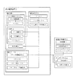
図2は、本願の第1実施形態に係る画像測定機を示すブロック図である。 FIG. 2 is a block diagram showing the image measuring machine according to the first embodiment of the present application.
〔情報処理装置2〕
情報処理装置2は、記憶装置11、中央処理装置12及びインターフェース13を有している。
[Information processing apparatus 2]
The information processing device 2 includes a storage device 11, a central processing device 12, and an interface 13.
記憶装置11には、使用者が測定点等を指定するために用いる後述の画像測定プログラムがインストールされている。また、記憶装置11は、試料観察装置3で撮像した画像データ、測定結果のデータ等のデータ保存等を行う。記憶装置11は、主記憶装置としてRAM(ランダムアクセスメモリ)、補助記憶装置としてハードディスク等の磁気ディスク、CD、DVD等の光ディスク、光磁気ディスク(MO)、USBメモリ、フラッシュメモリ等の半導体メモリを用いる事が出来る。
The storage device 11 is installed with an image measurement program, which will be described later, used by the user to specify measurement points and the like. The storage device 11 stores data such as image data captured by the
中央処理装置12は、使用者の指示に従ってプログラムを実行し、数値計算や情報処理、他の装置の制御等を行う。例えば、使用者が画像測定を行う場合、画像測定プログラムを実行し、使用者が測定点を指定するために必要な画像を撮像するように試料観察装置3へ指示を出し、試料観察装置3によって撮像された画像データに使用者の操作用のアイコンなどを付加した画像データをインターフェース13を介してタッチパネル4へ出力する。使用者がタッチパネル4に表示された画像を見ながら測定点を指定して測定の指示をした場合には、その指示に従って画像測定を行い、測定結果をインターフェース13を介してタッチパネル4へ出力する。なお、中央処理装置12は、測定結果をプリンターや外付けの記憶媒体などへ出力しても良い。
The central processing unit 12 executes a program in accordance with a user instruction, and performs numerical calculation, information processing, control of other devices, and the like. For example, when the user performs image measurement, the image observation program is executed, and the
〔試料観察装置3〕
試料観察装置3は、撮像装置6、電動ステージ8、及び、撮像装置支柱9を備えており、中央処理装置12の指示を受けて試料の画像を撮像する。
[Sample observation device 3]
The
撮像装置6は、CCD(電荷結合素子)撮像デバイス14と、CCD撮像デバイス14のCCD16上に像を結ぶための光学系15と、照明装置21とを有している。なお、照明装置21は撮像装置6と別体として構成しても良い。
The
CCD撮像デバイス14は、撮像素子としてのCCD16と、CCD16を制御するCCD制御回路17とを有しており、中央処理装置12からの指示により試料からの光をデジタルデータに変換して情報処理装置2へ出力する。 The CCD imaging device 14 includes a CCD 16 as an imaging device and a CCD control circuit 17 that controls the CCD 16, and converts light from the sample into digital data in accordance with an instruction from the central processing unit 12. Output to 2.
光学系15は、レンズ系18と、合焦機構19と、ズーム機構20とを備えている。 The optical system 15 includes a lens system 18, a focusing mechanism 19, and a zoom mechanism 20.
合焦機構19は、オートフォーカス機能と、マニュアルフォーカス機能とを有することが好ましい。 The focusing mechanism 19 preferably has an autofocus function and a manual focus function.
ズーム機構20は、情報処理装置2からの指示に従って電動により駆動するものであり、これにより、使用者が測定点付近を拡大して観察することができ、測定点を正確に指定することが可能となる。 The zoom mechanism 20 is electrically driven in accordance with an instruction from the information processing device 2, so that the user can enlarge and observe the vicinity of the measurement point, and can accurately specify the measurement point. It becomes.
照明装置21は、撮像装置6が撮像するために試料を照らすためのものである。照明装置21は撮像装置6のレンズ鏡筒前端部に円周方向に並べて配置されたLEDライトとし、円周方向の全周のみならず特定の部分のみを点灯することもできるように構成することが好ましい。例えば、円周方向に並んだLEDライトを隣り合うもの同士で8つのグループに分割し、グループごとに点灯と消灯をすることができるものとする。これにより、使用者の意図した向きから試料に照明光を当てることができ、試料の陰影のある画像を撮像することが可能となる。
The illumination device 21 is for illuminating the sample for the
電動ステージ8は、ステージ22と、ステージ用モータ23と、ステージ用モータ制御部24と、ステージ位置検出部32とを備えており、ステージ位置検出部32からの信号に基づく中央処理装置12からの指示を受けたモータ制御部24がステージ用モータ23を制御してステージ22を所望の位置へ移動させる。ステージ用モータ23として、ステッピングモータを用いる事が出来る。ステージ位置検出部32としては、XY方向それぞれに、例えば、エンコーダ、ポテンショメータ、レーザ距離センサなどを設置することができる。
The
撮像装置支柱9は、アーム10と、アーム用モータ25と、アーム用モータ制御部26とアーム位置検出部(不図示)とを備えており、アーム位置検出部からの信号に基づく中央処理装置12からの指示を受けたアーム用モータ制御部26がアーム用モータ25を制御し、アーム20を指示された高さへ移動させる。アーム用モータ25として、ステッピングモータを用いる事が出来る。アーム位置検出部としては、例えば、エンコーダ、ポテンショメータ、レーザ距離センサなどを設置することができる。
The imaging device support column 9 includes an
〔タッチパネル4〕
タッチパネル4は、表示装置27と、位置入力装置28とを備えており、情報処理装置2から出力された画像データを表示装置27において表示し、その画像を見ながら使用者がタッチパネル4の表面を押下し、それを位置入力装置28が感知して、入力された指示を情報処理装置2へ出力する。
[Touch panel 4]
The
〔操作方法〕
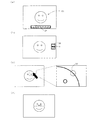
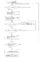
次に図3を参照しつつ、本第1実施形態に係る画像測定機1の操作とそれに伴う画像測定機1の作動について説明する。図3は、本第1実施形態に係る画像測定機1のタッチパネル4に表示される画像の表示例を示すイメージ図である。
〔Method of operation〕
Next, the operation of the
使用者が情報処理装置2の電源を入れると、オペレーティングシステム(OS)が起動し、タッチパネル4の電源を入れると、タッチパネル4の画面上に画像を拡大するためのアイコンや、画面の色補正をするためのアイコンなど、複数のアイコンが表示される。その中から画像測定メニューを示すアイコンを使用者が押下すると、記憶装置11に保存された画像測定プログラムが起動する。
When the user turns on the information processing apparatus 2, an operating system (OS) is activated, and when the
以下、画像測定プログラムに基づく使用者の操作と画像測定機1の作動とについて説明する。
Hereinafter, the user's operation based on the image measurement program and the operation of the
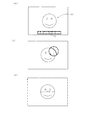
画像測定プログラムが起動すると、図3(a)に示すような画像測定のツールバー29と試料観察装置3によって撮像された電動ステージ8上の試料の画像P1が表示される。
When the image measurement program is activated, an image measurement tool bar 29 as shown in FIG. 3A and a sample image P1 on the
ツールバー29には、2点間距離の測定、円の径・円周等の測定、角度の測定、一の直線からの複数の点までの距離の測定などを行う機能を示すアイコンが表示される。図面においてアイコンの表示は詳細を省略しているが、使用者がそのアイコンを押下して用いる機能の内容を容易に理解することができる記号や図形とすることが好ましい。なお、ツールバー29の位置や大きさは図3(a)に示すものに限られず、また、設定によって使用者が位置や大きさを変更することが出来るものとしても良い。 The tool bar 29 displays icons indicating functions for measuring the distance between two points, measuring the diameter and circumference of a circle, measuring the angle, and measuring the distance from a single straight line to a plurality of points. . Although details of the icon display are omitted in the drawings, it is preferable to use symbols and figures that allow the user to easily understand the contents of the function used by pressing the icon. Note that the position and size of the tool bar 29 are not limited to those shown in FIG. 3A, and the user can change the position and size by setting.
ツールバー29の複数のアイコンから使用者が実行する測定機能を示すアイコンを押下すると、図1(b)に示すように、画面右側に画像拡大アイコン30と、測定点指定アイコン31とが表示される。表示された時点においては、情報処理装置2は、画像拡大アイコンが選択されたものと認識しており、画像拡大アイコン30が押下されて凹んでいるようにタッチパネル4に表示される。なお、画像拡大アイコン30と測定点指定アイコン31の位置や大きさはこれに限られるものではなく、また、設定によって使用者が位置や大きさを変更することができるものとしても良い。
When an icon indicating a measurement function to be executed by the user is pressed from a plurality of icons on the toolbar 29, an
この状態で使用者が画像を拡大したい位置を押下すると、図3(c)に示すように、押下した点を中心に画像が拡大される。図3(c)においては、図面に向かって左側が拡大前の画像、右側が押下した点を中心として拡大された画像を示している。 In this state, when the user presses the position where the image is desired to be enlarged, as shown in FIG. 3C, the image is enlarged around the pressed point. In FIG. 3C, the left side of the drawing shows the image before enlargement, and the right side shows the image enlarged around the point pressed.
画像の拡大率はあらかじめ決められていても良いが、使用者が1回の拡大をどの程度の拡大率とするかを設定できるようにしても良い。また、タッチパネル4を感圧式のタッチパネルとして、タッチパネル4が感知した押下の圧力に応じて拡大率を変化させても良い。例えば、押下する圧力が高い場合には表示倍率が高く、押下する圧力が低い場合には表示倍率が低いものとすることができる。
The enlargement ratio of the image may be determined in advance, but the user may be allowed to set how much enlargement ratio is used for one enlargement. In addition, the
指定したい部分が十分に拡大され、使用者が、測定点指定アイコン31を押下した後に測定点とする部分を押下すると、情報処理装置2が測定点を確定し、タッチパネル4に測定点を示す目印33を表示させる。一方、使用者が指定したい部分が十分に拡大されていないと判断した場合、測定点指定アイコン31を押下しなければ画像拡大アイコン30が選択されたままとなり、使用者が再度拡大したい点を押下して、十分に拡大されてから測定点指定アイコン31を押下して測定点とする位置を押下する。測定点指定アイコン31を押下したものの、使用者が十分に画像が拡大されていないと判断した場合には、画像拡大アイコン30を押下すると、情報処理装置2によって再度画像を拡大することができる状態に戻される。なお、測定点を指定した後に測定点を示す目印をドラッグすること等により測定点の位置を調整できるようにしても良い。ドラッグによる調整を可能とする場合、下記第2実施形態において説明するように、タッチパネルの感知した座標と使用者が指定する点とのずれを調整する機能を有してもよい。
When the part to be specified is sufficiently enlarged and the user presses the part to be measured after pressing the measurement
測定点の指定は、例えば、2点間測定であれば、その2点を指定し、円の径・円周等の測定であれば、円上の点を3点指定するなど、測定内容に応じて行う。使用者が測定点指定アイコン31にタッチして測定点を指定する段階で、情報処理装置2によってタッチパネル4に測定点をどのように指定する必要があるのかを表示することが好ましい。
The measurement points can be specified by specifying two points if measuring between two points, and specifying three points on a circle if measuring the diameter and circumference of a circle. Do it accordingly. When the user touches the measurement
測定点を複数指定する場合、一つ目の測定点の指定が終わるとタッチパネル4に表示された画像が再び拡大する前の図3(b)に示す状態に戻り、使用者は一つ目の測定点の指定と同様の操作を全ての測定点を指定するまで繰り返す。
When a plurality of measurement points are specified, when the first measurement point is specified, the image displayed on the
全ての測定点が指定されると、情報処理装置2によって画像測定が行われ、図3(d)に示すように、タッチパネル4に拡大前の試料の画像が表示され測定結果が試料の画像上に重ねて表示(オーバーレイ)される。画像測定は、例えば、2点間の距離の測定においては、CCDのピクセル間距離と画像の倍率から画像の1ピクセルあたりの長さを計算し、その長さに2点間に存在する画像のピクセルの数を掛けることにより行うことができる。又は、前もってスケールを使用して基準倍率の画像の1ピクセルあたりの基準長さを測定しておき、その基準長さと実際の画像の倍率とから1ピクセルあたりの長さを計算し、その長さに2点間に存在するピクセルの数を掛けることにより行うことが出来る。また、面積の測定においては、面積の計算に必要な距離を測定して計算することができる他、画像の倍率を掛け合わせることで1ピクセル当たりの面積を算出し、その面積に測定の対象となっている面の中に含まれるピクセルの数を掛けることで計算することができる。
When all the measurement points are specified, image measurement is performed by the information processing apparatus 2, and an image of the sample before enlargement is displayed on the
〔試料画像の拡大〕
上述した試料画像の拡大は、光学ズーム又は電子ズームを単独で用いる方法と、光学ズーム及び電子ズームを併用する方法の、いずれも用いる事ができる。光学ズームの例として、デジタルマイクロスコープ「ShuttlePix」(登録商標)では、光学ズーム倍率が20倍のものが市販されている。
[Enlargement of sample image]
For the above-described enlargement of the sample image, either a method using an optical zoom or an electronic zoom alone or a method using both an optical zoom and an electronic zoom can be used. As an example of optical zoom, a digital microscope “ShuttlePix” (registered trademark) having an optical zoom magnification of 20 times is commercially available.
光学ズームを用いる場合、使用者が拡大の中心点としてその時点で撮像装置6が撮像している中心点以外を指定した場合、情報処理装置2は、両中心点間の(X、Y)座標の差分を算出し、情報処理装置2から電動ステージ8へ、試料の指定された部分が撮像装置6が撮像する画像の中心に位置するように動かす向き及び動かす距離の指示が出され、電動ステージ8が試料を動かすとともに、ステージ位置検出部32にて位置検出が行われ、位置調整が行われる。また、情報処理装置2から電動ズーム機構20へズーム倍率を上げるように指示が出され、電動ズーム機構20がズーム倍率を上げ、撮像装置6が試料を撮像して、撮像した画像データを情報処理装置2へ出力する。
When the optical zoom is used, when the user designates a center point other than the center point that the
一方、電子ズームを用いる場合、使用者が拡大の中心点としてタッチパネル4にタッチした部分を中心として、中央処理装置12が電子ズームを行う。本第1実施形態に係る画像測定機1は試料観察装置3を備えているが、電子ズームのみを用いる場合には、試料観察装置3を備えなくても良く、例えば、既に撮像された画像データを記憶した記憶装置11から読み出して、その画像データを電子ズームによって拡大して用いることもできる。
On the other hand, when the electronic zoom is used, the central processing unit 12 performs the electronic zoom around the portion where the user touches the
光学ズームと電子ズームを併用する場合は、タッチパネル4の解像度と画像の解像度が等しくなる倍率までは電子ズームを用い、解像度が等しくなった後は光学ズームを用いて画像を拡大する。光学ズームが最高倍率になった後は、再び電子ズームを用いる。これにより、光学的な分解能と画像の分解能を効率的に利用する事が出来る。
When the optical zoom and the electronic zoom are used in combination, the electronic zoom is used up to a magnification at which the resolution of the
〔エッジ検出〕
測定点の指定に際し、タッチパネル4にエッジ検出により得られた特徴点を測定点の候補として表示することもできる。例えば、図4(a)に示すように、エッジ検出の特徴点を番号と共に目印によって表示し、使用者が番号が付された目印を押下することで、測定点がその特徴点の位置に確定する。又は、画像測定機がキーボードを備える場合には、キーボードによって番号を指定することで、測定点がその特徴点の位置に確定する。なお、目印の形状はこれに限られず、キーボードを用いない場合には番号が付されていなくても良い。エッジ検出法としては、キャニー法や微分エッジ検出法など公知の方法を用いる事が出来る。
〔Edge detection〕
When designating measurement points, feature points obtained by edge detection can be displayed on the
当該特徴点の表示は、タッチパネル上の操作によって表示と非表示とを切り替えられるようにする事が好ましい。例えば、図4(b)に示すように、タッチパネル4の表面に丸を描くようにドラッグすると特徴点の表示と非表示が切り替わるようにすることができる。また、図4(c)に示すように、タッチパネル4の特徴点以外の部分を連続して2回押下(ダブルタッチ)することで、特徴点の表示と非表示が切り替わるようにすることができる。
It is preferable that display of the feature points can be switched between display and non-display by an operation on the touch panel. For example, as shown in FIG. 4B, the feature points can be switched between display and non-display by dragging a circle on the surface of the
(第2実施形態)
次に、本願の第2実施形態に係る画像測定機について説明する。本第2実施形態に係る画像測定機のハードウェアの構成は上記第1実施形態に係る画像測定機1と同様である。本第2実施形態に係る画像測定機は、画像測定プログラムに基づく使用者の操作と画像測定機の作動において第1実施形態に係る画像測定機と異なるため、以下、これについて説明する。なお、図1及び図2に記載された参照符号は第2実施形態の説明においても同じ番号を使用する。
(Second Embodiment)
Next, an image measuring machine according to a second embodiment of the present application will be described. The hardware configuration of the image measuring machine according to the second embodiment is the same as that of the
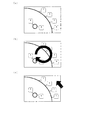
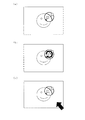
図5は、本第2実施形態に係る画像測定機のタッチパネル4に表示される画像の表示例を示すイメージ図である。
FIG. 5 is an image diagram showing a display example of an image displayed on the
使用者が情報処理装置2の電源を入れると、オペレーティングシステム(OS)が起動し、タッチパネル4の電源を入れると、タッチパネル4の画面上に画像を拡大するためのアイコンや、画面の色補正をするためのアイコンなど、複数のアイコンが表示される。その中から画像測定メニューを示すアイコンを押下すると、記憶装置11に保存された画像測定プログラムが起動する。
When the user turns on the information processing apparatus 2, an operating system (OS) is activated, and when the
画像測定プログラムが起動すると、撮像装置はフレームレート毎に高解像度のライブ画像P1を情報処理装置2内のRAMに取り込む(以降、このライブ画像を「フレーム画像」という)。RAMに取り込まれたフレーム画像のデータは、図5(a)に示すような画像測定のツールバー32の画像と合成されて情報処理装置2からタッチパネル4へ出力され、タッチパネル4に表示される。一般に、タッチパネル4はフレーム画像より解像度の低い場合が多いが、その場合、フレーム画像はタッチパネル4の寸法と解像度に合わせて、フレーム画像全体が表示される。
When the image measurement program is activated, the imaging apparatus captures a high-resolution live image P1 for each frame rate into the RAM in the information processing apparatus 2 (hereinafter, this live image is referred to as “frame image”). The frame image data captured in the RAM is combined with the image of the image
使用者が、タッチパネル4に表示された画像を見ながら、測定点にしようとする部分が表示されているタッチパネル4の部分を押下すると、図5(b)に示すように、例えば、タッチパネル4から出力されたデータに基づいて、情報処理装置2が使用者の指定する点であると判断した座標を中心とする円とその円の中心を通る破線の十字線(以降、この円と十字線を「指定点の表示」と呼ぶ。)がタッチパネル4上に描画され、使用者はその座標の位置を正確に認識することができる。これにより、タッチパネル4において使用者の意図する座標とタッチパネル4が感知した座標との間にずれが生じたとしても、使用者は画像測定機1が指定点と判断した位置を正確に知ることができる。なお、指定点の表示は円と破線の十字線に限らず、例えば、四角とその対角線でも、円や四角が無くても良く、種々変更が可能である。
When the user presses the part of the
使用者がタッチパネル4を指やペンで押下した場合、通常、タッチパネル4に対してある程度の面積をもって接触することになるが、その場合、情報処理装置2は、その中心点が指定されたものとして処理しても良いし、その範囲内の所定の部分が指定されたものとして処理しても良い。ただし、使用者が指等で押下するような場合、使用者は指等に隠れた部分の画像を見ることができないため、情報処理装置2は、接触範囲から所定の方向に所定の距離離れた位置が指定されたものとして処理しても良い。例えば、情報処理装置2は、接触範囲のうち最も上側の部分から上方へ3cm程度離れた位置が指定されたものとして処理する事が出来る。この場合、接触範囲からどの程度離れた位置とするか、及び、接触範囲からどの方向へ離れた位置とするかは、使用者が設定により種々変更することができるようにしても良い。
When the user presses the
また、使用者がタッチパネル4に表示された画像の中で測定点とする部分を押下すると、情報処理装置2は、タッチパネルが押下された時点でのフレーム画像をRAM上に保持する(以降、このフレーム画像を「保持フレーム画像」と呼ぶ。)。そして、タッチパネル4から押下された座標のデータが情報処理装置2へ出力され、その座標のデータから情報処理装置2が指定点であると判断した点を中心として拡大画像を撮像するように撮像装置6へ指示が出され、指示を受けた撮像装置6は、光学倍率を高倍にして、指示された点を中心とする試料の拡大画像を撮像し、画像データを情報処理装置2へ出力する。画像の撮像位置の移動、調整については上記第1実施形態と同様である。
When the user presses a portion to be measured in the image displayed on the
タッチパネル4が拡大画像を表示するためには、上記のように光学倍率を高倍にして撮像する他、撮像装置の出力解像度を高解像度に操作したり、情報処理装置2において電子ズームによって画像を拡大したりすることもできる。
In order for the
撮像装置6から出力された画像データを受け取った情報処理装置2は、以降撮像装置6からフレームレート毎に都度出力される拡大画像(ライブ画像)を、保持フレーム画像上の指定点の表示と共に合成した画像データとして出力し、タッチパネル4は、図5(b)に示すように、その画像を表示する(以下、保持フレーム画像よりも拡大された範囲を「注目範囲」と呼ぶ。)。
The information processing apparatus 2 that has received the image data output from the
指定点の表示と注目範囲の大きさ(以下、単に「注目範囲の広さ」として説明する。)は、タッチパネル4を圧力感知機能付きのものとしておき、情報処理装置2が、タッチパネル4が感知した押下の圧力に応じて変化させるようにしても良い。例えば、強く押されている時は注目範囲を広く、弱い時は注目範囲を狭くすることで、使用者は直感的な操作によって注目範囲の広さを調整することが可能となる。どの程度の押下の圧力によってどの程度注目範囲の広さが変化するのかは、使用者が設定によって調整できるようにしておく事が好ましい。
The display of the designated point and the size of the attention range (hereinafter simply referred to as “the width of the attention range”) are determined with the
又は、タッチパネル4を圧力感知機能付きのものとしておき、注目範囲の画像の表示倍率は、情報処理装置2が、タッチパネル4が感知した押下の圧力に応じて変化させるようにしても良い。例えば、強く押されている時は注目範囲の表示倍率が高く、弱い時は注目範囲の表示倍率は低くすることで、使用者は直感的な操作によって表示倍率を調整することが可能となる。どの程度の押下の圧力によってどの程度表示倍率が変化するのかは、使用者が設定によって調整できるようにしておく事が好ましい。
Alternatively, the
若しくは、これらを組み合わせて、注目範囲の広さと表示倍率は、強く押されている時には注目範囲が広く表示倍率が高く、弱く押されている時には注目範囲が狭く表示倍率が低くなるように、情報処理装置2が処理しても良い。 Or, by combining these, the range of interest and the display magnification can be set so that the area of interest is wide and the display magnification is high when pressed hard, and the area of interest is narrow and the display magnification is low when pressed weakly. The processing device 2 may perform processing.
なお、光学ズームと電子ズームを併用する場合、画像の拡大は、第1実施形態と同様にタッチパネル4の解像度と画像の解像度が等しくなる倍率までは電子ズームを用い、解像度が等しくなると光学ズームを用いて画像を拡大し、光学ズームが最高倍率になると、再び電子ズームを用いるようにする事ができる。
When the optical zoom and the electronic zoom are used together, the image is enlarged using the electronic zoom up to a magnification at which the resolution of the
使用者は、タッチパネル4を押下して表示された指定点が意図する位置と異なる場合には、タッチパネル4を押下している指等をタッチパネル4を押下したままタッチパネル4上をずらす(ドラッグする)と、情報処理装置2によって、それに追従して指定点の表示と注目範囲が移動するように処理される。そして、使用者が、指定点が意図する点に重なったと判断した場合に、タッチパネル4から指を離すと、情報処理装置2がその時の指定点の位置を測定点として確定し、タッチパネル4に測定点を示す目印を表示する。本第2実施形態によれば、画像全体が表示された上に注目範囲が表示されるため、注目範囲が画像全体のどの部分を示しているのかを使用者が認識し易いものとなる。
When the specified point displayed by pressing the
情報処理装置2は、使用者の意図する指定点と、タッチパネルの感知した座標とのずれを調整する機能を有することが好ましい。具体的には、使用者が最初に測定点の指示としてタッチパネル4を押下した時点での指定点の位置(位置1)と、その後使用者がドラッグ操作で移動して押下した指をタッチパネル4から離して確定した測定点の位置(位置2)を記憶しておき、位置1と位置2のペアの記憶が複数個記憶でき、位置1と位置2の移動方向と距離に傾向が確認できた場合に、情報処理装置2は、タッチパネルの認識点と使用者の意図している指定点にずれがあるとみなして指定点の位置を調整する。例えば、測定点の指定を3回行った時に、3回とも位置1に対して位置2が右にずれている場合は、次回からタッチパネルの認識点は、位置1と位置2の右へのずれの3回の平均分、右にずらした点が指示されたものとして処理する。上下方向も同様である。
The information processing apparatus 2 preferably has a function of adjusting a deviation between a designated point intended by the user and coordinates detected by the touch panel. Specifically, the position of the designated point (position 1) when the user first presses the
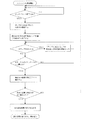
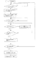
本第2実施形態に於ける測定開始から測定完了までのフローを図6に示す。 FIG. 6 shows a flow from the start of measurement to the completion of measurement in the second embodiment.
情報処理装置2は、図7(a)に示すように、注目範囲内でエッジ検出により得られた特徴点を測定点の候補として表示した画像データをタッチパネル4へ出力してもよい。例えば、エッジ検出の特徴点を番号と共に表示し、タッチパネル4のドラッグ操作によって指定点を特徴点の番号に重ね合わせると、指定点は特徴点へ移動する。その状態でパネルから押下している指等を離すと、情報処理装置2がその特徴点の位置を測定点として確定し、タッチパネル4上に目印を表示させる。指定点の表示が特徴点に移動した後に他の特徴点や特徴点以外の部分を指定するためには、タッチパネル4を押下している指等を一定距離以上ドラッグすれば、指定点の表示が特徴点から離れて、特徴点の番号に重ね合わせる前の状態に戻るように情報処理装置2によって処理される。
As illustrated in FIG. 7A, the information processing apparatus 2 may output image data in which feature points obtained by edge detection within a range of interest are displayed as measurement point candidates to the
特徴点の表示と非表示は、使用者の指示によって切り替えられるようにしても良い。例えば、図7(b)に示すように、測定点の指定のために押下している指等でタッチパネル4上に丸を描かれたと感知した場合に、情報処理装置2が特徴点の表示と非表示を切り替えるようにしても良い。または、タッチパネル4を複数の接触点を検出することができるマルチタッチパネルやタッチFLO等としておき、図7(c)に示すように、測定点付近の注目範囲の外を、指定点を指定している指等以外の指等によってダブルタッチ等することで、特徴点の表示と非表示を切り替えられるようにしても良い。
The display and non-display of the feature points may be switched according to a user instruction. For example, as shown in FIG. 7B, when the information processing apparatus 2 detects that a circle is drawn on the
必要な測定点が全て指定されると、上記第1実施形態と同様に、情報処理装置2によって長さ等の計算が成され、測定結果をフレーム画像上にオーバーレイした画像データが出力され、図5(c)に示すようにタッチパネル4に表示される。
When all necessary measurement points are designated, the length and the like are calculated by the information processing device 2 as in the first embodiment, and image data in which the measurement result is overlaid on the frame image is output. It is displayed on the
(第3実施形態)
次に、本願の第3実施形態に係る画像測定機について説明する。本第3実施形態に係る画像測定機のハードウェアの構成は、上記第1実施形態に係る画像測定機と同様である。本第3実施形態に係る画像測定機は、画像測定プログラムに基づく使用者の操作と画像測定機の作動において第1実施形態に係る画像測定機と異なるため、以下、これについて説明する。なお、図1及び図2に記載された参照符号は本第3実施形態の説明においても同じ番号を使用する。
(Third embodiment)
Next, an image measuring machine according to a third embodiment of the present application will be described. The hardware configuration of the image measuring machine according to the third embodiment is the same as that of the image measuring machine according to the first embodiment. Since the image measuring machine according to the third embodiment is different from the image measuring machine according to the first embodiment in the operation of the user and the operation of the image measuring machine based on the image measuring program, this will be described below. Note that the same reference numerals are used in the description of the third embodiment as the reference numerals described in FIGS. 1 and 2.
本第3実施形態は、画像測定プログラムに基づいて使用者が測定点を指定する操作と画像測定機1の作動が部分的に上記第2実施形態と異なるが、それ以外は上記第2実施形態と同様である。したがって、第2実施形態と異なる部分について以下説明する。
The third embodiment is different from the second embodiment in the operation of the user specifying the measurement point based on the image measurement program and the operation of the
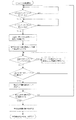
図8は、本第3実施形態に係る画像測定機の測定開始から測定完了までの処理の流れを示すフローチャートである。 FIG. 8 is a flowchart showing the flow of processing from the start of measurement to the end of measurement of the image measuring machine according to the third embodiment.
本第3実施形態においては、使用者はメニュー画面から画像測定メニューを示すアイコンを押下して、画像測定プログラムを起動させた後、例えば、使用者は左手の指でタッチパネル4を押下する(1回目の押下)。この左手での押下は、測定点の位置とは関係が無く、単に測定点の指定が継続されていることを情報処理装置2に認識させるものである。使用者が、左手での押下を継続しながら、右手の指で測定点となる点を押下する(2回目の押下)。2回目の押下がされたと認識した情報処理装置2は、第2実施形態と同様に指定点の表示と注目範囲の画像を保持フレーム画像に合成した画像データをタッチパネル4へ出力する。
In the third embodiment, after the user presses an icon indicating the image measurement menu from the menu screen to start the image measurement program, for example, the user presses the
情報処理装置2は、左手の押下がタッチパネル4から離れない限り測定点を確定させない。したがって、使用者は、右手を一度タッチパネル4から離しても良い。右手をタッチパネル4から離しても注目範囲は右手が最後にタッチパネル4を押下していた位置に表示され続け、使用者が指定点を移動させる場合には再度右手でタッチパネル4を押下して移動させることができる。
The information processing apparatus 2 does not fix the measurement point unless the left hand is pressed away from the
使用者は、指定点が測定点とすべき位置に重なったと判断した時に、左手をタッチパネル4から離すと、それによって情報処理装置2がその時の指定点の位置を測定点として確定する。このように構成することで、第2実施形態と異なり、指定点を動かす指や手、腕等にタッチパネル4が隠れずに、タッチパネル4に表示された画像全体を見ながら測定点の位置を指定することができる。
When the user determines that the designated point has overlapped with the position to be the measurement point, when the user moves his left hand away from the
なお、ドラッグを一度離した後の2回目以降のドラッグにおいては、1回目のドラッグと同様に、指等で最初に押圧した位置、又は、そこから一定の方向で一定の距離を離した位置を指定点として、その後はドラッグに追従して注目範囲が移動するように、情報処理装置2がしても良いし、若しくは、1回目のドラッグとは異なり、1回目のドラッグにおいて指定した指定点と2回目以降のドラッグの際に最初に押圧した位置との位置関係を保ちつつ注目範囲がドラッグに連動して移動するように、情報処理装置2が処理しても良い。 In the second and subsequent drags after the drag is released once, the position where the finger is first pressed with the finger or the position where a certain distance is removed from it is the same as the first drag. As the designated point, the information processing apparatus 2 may be configured so that the attention range moves following the drag, or the designated point designated in the first drag is different from the first drag. The information processing apparatus 2 may perform processing so that the range of interest moves in conjunction with the drag while maintaining the positional relationship with the position pressed first in the second and subsequent drags.
第2実施形態において説明したように、タッチパネル4の押下の圧力に応じて注目範囲の広さ又は表示倍率を変化させる場合、若しくは、注目範囲の広さ及び表示倍率を変化させる場合、上記の例において、指定点を動かす右手によってタッチパネル4が押下されている圧力が一定の変化率以上で低下して離れた場合、情報処理装置2は、注目範囲の広さや表示倍率を変化させる指示ではないと認識し、押下圧力が低下する前の注目範囲の広さ又は表示倍率の画像を維持するようにしても良い。又は、指定点を動かす右手が離れた場合には、情報処理装置2は、あらかじめ設定された注目範囲の広さ又は表示倍率の画像データを出力するようにしても良い。
As described in the second embodiment, when the size of the attention range or the display magnification is changed according to the pressing pressure of the
(第4実施形態)
次に、本願の第4実施形態に係る画像測定機について説明する。本第4実施形態に係る画像測定機のハードウェアの構成は、上記第1実施形態に係る画像測定機と同様である。本第4実施形態に係る画像測定機は、画像測定プログラムに基づく使用者の操作と画像測定機の作動において上記第1乃至第3実施形態に係る画像測定機と異なるため、以下、これについて説明する。なお、図1及び図2に記載された参照符号は本第4実施形態の説明においても同じ番号を使用する。
(Fourth embodiment)
Next, an image measuring machine according to a fourth embodiment of the present application will be described. The hardware configuration of the image measuring machine according to the fourth embodiment is the same as that of the image measuring machine according to the first embodiment. Since the image measuring machine according to the fourth embodiment is different from the image measuring machine according to the first to third embodiments in the operation of the user and the operation of the image measuring machine based on the image measuring program, this will be described below. To do. The same reference numerals are used in the description of the fourth embodiment as the reference numerals described in FIGS. 1 and 2.
本第4実施形態は、画像測定プログラムに基づいて使用者が測定点を指定する操作と画像測定機1の作動が部分的に上記第2実施形態と異なるが、それ以外は上記第2実施形態と同様である。したがって、第2実施形態と異なる部分について以下説明する。
The fourth embodiment is partially different from the second embodiment in the operation of the user specifying the measurement point based on the image measurement program and the operation of the
図9は、本第4実施形態に係る画像測定機の測定開始から測定完了までの処理の流れを示すフローチャートである。 FIG. 9 is a flowchart showing the flow of processing from the start of measurement to the end of measurement of the image measuring machine according to the fourth embodiment.
本第4実施形態においては、使用者が、メニュー画面から画像測定メニューを示すアイコンを押下して、画像測定プログラムを起動させた後、タッチパネル4を押下すると、情報処理装置2は、押下した点が指定されたものとして指定点の表示と注目範囲の画像とを合成した画像データを出力し、タッチパネル4はその画像を表示する。ここまでは、上記第2実施形態と同様である。
In the fourth embodiment, when the user presses the
しかし、本第4実施形態においては、上記第2実施形態と異なり、タッチパネル4がダブルタッチされた時に、情報処理装置2がその時点の指定点を測定点として確定する点において異なっている。したがって、一度タッチパネル4を押下している指等をタッチパネル4から離しても測定点が確定しないため、使用者は、タッチパネル4から指等を離して画像全体を見ることができる状態で指定点の位置を確認し、意図する位置からずれている場合には再度タッチパネル4をドラッグして、指定点を移動することができる。そして、使用者が意図する位置に指定点の表示が重なったと判断した時に、タッチパネル4上にダブルタッチすると、情報処理装置2がその時点の指定点の位置を測定点として確定する。
However, the fourth embodiment differs from the second embodiment in that when the
なお、ドラッグを一度離した後の2回目以降のドラッグにおける指定点の移動と、タッチパネル4の押下の圧力に応じて注目範囲の広さ又は表示倍率を変化させる場合については、上記第3実施形態と同様である。
Note that the third embodiment is described with respect to the case where the designated point is moved in the second and subsequent drags after the drag is released once and the size of the range of interest or the display magnification is changed in accordance with the pressing pressure on the
(第5実施形態)
次に、本願の第5実施形態に係る画像測定機について説明する。本第5実施形態に係る画像測定機のハードウェアの構成は、上記第1実施形態に係る画像測定機と同様である。本第5実施形態に係る画像測定機は、画像測定プログラムに基づく使用者の操作と画像測定機の作動において上記第1乃至第4実施形態に係る画像測定機と異なるため、以下、これについて説明する。なお、図1及び図2に記載された参照符号は本第5実施形態の説明においても同じ番号を使用する。
(Fifth embodiment)
Next, an image measuring machine according to a fifth embodiment of the present application will be described. The hardware configuration of the image measuring machine according to the fifth embodiment is the same as that of the image measuring machine according to the first embodiment. Since the image measuring machine according to the fifth embodiment is different from the image measuring machines according to the first to fourth embodiments in the operation of the user and the operation of the image measuring machine based on the image measuring program, this will be described below. To do. Note that the same reference numerals as those in FIGS. 1 and 2 are used in the description of the fifth embodiment.
本第5実施形態は、画像測定プログラムに基づいて使用者が測定点を指定する操作と画像測定機1の作動が部分的に上記第2実施形態と異なるが、その他は上記第2実施形態と同様である。したがって、第2実施形態と異なる部分について以下説明する。
The fifth embodiment is partially different from the second embodiment in the operation of the user specifying the measurement point based on the image measurement program and the operation of the
図10は、本第5実施形態に係る画像測定機の測定開始から測定完了までの処理の流れを示すフローチャートである。 FIG. 10 is a flowchart showing the flow of processing from the start of measurement to the completion of measurement of the image measuring machine according to the fifth embodiment.
本第5実施形態においては、使用者が、メニュー画面から画像測定メニューを示すアイコンを押下して、画像測定プログラムを起動させた後、タッチパネル4を押下すると、情報処理装置2は、押下した点が指定されたものとして指定点の表示と注目範囲の画像とをフレーム画像に合成した画像データを出力し、その画像がタッチパネル4に表示される。ここまでは、上記第2実施形態と同様である。
In the fifth embodiment, when the user presses the
しかし、本第5実施形態においては、上記第2実施形態と異なり、1回目に押下した指等をタッチパネル4から離しても測定点は確定されない。使用者が2回目の押下を行ってドラッグすると、情報処理装置2は、指定点の表示と注目範囲とを2回目に最初に押下した位置との位置関係を保ちながらドラッグに連動して移動させ、2回目の押下によるドラッグをしている指等がタッチパネル4から離れた時に、その時点の指定点の位置を測定点として確定し、測定点をタッチパネル4に表示させる。これにより、使用者は、一度タッチパネル4から指等を離して、タッチパネル4に表示された画像全体を見てから指定点の位置を調整することが可能となる。
However, in the fifth embodiment, unlike the second embodiment, the measurement point is not fixed even if the finger pressed for the first time is released from the
タッチパネル4の押下の圧力に応じて注目範囲の広さ又は表示倍率を変化させる場合については、上記第3実施形態と同様である。
The case where the range of interest or the display magnification is changed according to the pressure of pressing the
上記第2実施形態乃至第5実施形態において、部分的に試料の拡大画像を表示する画像測定プログラムに基づく使用者の操作と画像測定機の作動について具体的な実施形態を示したが、本発明はこれに限られるものではない。上記の第2乃至第5実施形態から、測定点の確定のためには、画像測定プログラムにおいて、情報処理装置2が、使用者の操作によって(ア)測定点を指定する作業を開始すること、(イ)指定点の位置を調整するドラッグを開始すること、(ウ)指定点の位置を調整するドラッグを終了すること、(エ)指定点の位置を調整する作業を終了したこと、を認識できるように構成すれば良いということが理解できる。また、上記(ア)と(イ)、並びに、上記(ウ)と(エ)は、例えば、第2実施形態のように、使用者による一つの操作によって認識されるものとしても良いことが理解できる。 In the second to fifth embodiments, specific embodiments of the user's operation and the operation of the image measuring machine based on the image measurement program that partially displays the enlarged image of the sample have been described. Is not limited to this. From the above second to fifth embodiments, in order to determine the measurement point, in the image measurement program, the information processing apparatus 2 starts (a) the operation of designating the measurement point by the user's operation. (B) Recognize that the drag that adjusts the position of the specified point starts, (c) that the drag that adjusts the position of the specified point ends, and (d) that the work that adjusts the position of the specified point has ended. It can be understood that it should be configured so that it can. Further, it is understood that the above (a) and (b) and the above (c) and (d) may be recognized by a single operation by the user as in the second embodiment, for example. it can.
画像測定機は、上記第1乃至第5実施形態に係る画像測定プログラムや上記のように第2乃至第5実施形態から理解される画像測定プログラムを複数備え、使用者が設定によってどの画像測定プログラムによって画像測定を行うかを選択できるようにしても良いし、一つの画像測定プログラムにおいて上記異なる操作を選択できるようにしても良い。 The image measuring machine includes a plurality of image measuring programs according to the first to fifth embodiments and the image measuring programs understood from the second to fifth embodiments as described above, and which image measuring program is set by the user according to the setting. It may be possible to select whether image measurement is to be performed or to select different operations in one image measurement program.
なお、上記全ての実施形態におけるタッチパネル4の操作方法において、押下(シングルタッチ)、ダブルタッチ、トリプルタッチ、丸を描くなどのアクション等を相互に入れ替えても良い。
In the operation methods of the
以上のように、本発明によれば、タッチパネルを用いて正確な測定を可能とする画像測定用プログラム、画像測定機、及び画像測定方法を提供することができる。 As described above, according to the present invention, it is possible to provide an image measurement program, an image measurement machine, and an image measurement method that enable accurate measurement using a touch panel.
(請求項1)
コンピュータに、
使用者が画像測定の基準点となる測定点を指定する前に試料画像の拡大表示のためのタッチパネルの操作を行うことを可能とし、これによって該タッチパネルから出力されたデータに基づいて、前記使用者が前記操作によって指定した点を中心として拡大した前記試料画像を含む画像データを前記タッチパネルへ出力する画像出力機能と、
前記使用者が前記測定点が未指定の拡大した前記試料画像を見ながら行う前記タッチパネルの操作によって前記測定点が未指定の拡大した前記試料画像に対して前記測定点を指定することを可能とし、これによって該タッチパネルから出力された前記測定点の指定に対応するデータに基づいて、前記測定点を確定する測定点確定機能と、
前記測定点を用いて前記画像測定を行う画像測定機能と、
前記画像測定機能によって測定された結果を出力する結果出力機能と、
を実現させることを特徴とする画像測定用プログラム。
(請求項2)
請求項1に記載の画像測定用プログラムを記憶した記憶媒体。
(請求項3)
請求項2に記載の記憶媒体を備えたコンピュータと、
該コンピュータに接続されたタッチパネルと、を有し、
前記画像測定用プログラムを用いて画像測定を行うことを特徴とする画像測定機。
(請求項4)
請求項2に記載の記憶媒体を備えたコンピュータと、
該コンピュータに接続されたタッチパネルと、
該コンピュータに接続された撮像装置と、を有し、
前記画像測定用プログラムの前記画像出力機能は、前記使用者が前記測定点を指定する操作を開始した時点における前記試料のフレーム画像と、前記使用者が指定した点を中心として拡大した前記撮像装置が撮像している前記試料のライブ画像とを合成した画像を前記タッチパネルに表示させることを特徴とする画像測定機。
(請求項5)
請求項2に記載の記憶媒体を備えたコンピュータと、
該コンピュータに接続されたタッチパネルと、
該コンピュータに接続された撮像装置と、
該コンピュータに接続され、前記撮像装置と前記試料を支持し、前記撮像装置と前記試料を相対移動させる電動支持装置と、を有し、
請求項1に記載の画像測定プログラムを用いて、前記画像出力機能において、前記電動支持装置が前記撮像装置と前記試料とを相対移動させて、前記撮像装置が撮像している前記試料の画像を拡大した前記試料画像として画像測定することを特徴とする画像測定機。
(請求項6)
コンピュータが備える画像出力機能が、使用者が画像測定の基準点となる測定点を指定する前に試料画像の拡大表示のためのタッチパネルの操作を行うことを可能とし、これによって該タッチパネルから出力されたデータに基づいて、前記使用者が前記操作によって指定した点を中心として拡大した前記試料画像を含む画像データを前記タッチパネルへ出力するステップと、
コンピュータが備える測定点確定機能が、前記使用者が前記測定点が未指定の拡大した前記試料画像を見ながら行う前記タッチパネルの操作によって前記測定点が未指定の拡大した前記試料画像に対して前記測定点を指定することを可能とし、これによって前記タッチパネルから出力された前記測定点の指定に対応するデータに基づいて、前記測定点を確定するステップと、
コンピュータが備える画像測定機能が、前記測定点を用いて前記画像測定を行うステップと、
コンピュータが備える結果出力機能が、前記画像測定機能によって測定された結果を出力するステップと、
を実行することを特徴とする画像測定方法。
(Claim 1)
On the computer,
It is possible to operate the touch panel for the enlarged display of the sample image before the user designates the measurement point that becomes the reference point of the image measurement, and based on the data output from the touch panel, the use An image output function for outputting image data including the sample image enlarged around the point designated by the operation by the person to the touch panel;
The user can designate the measurement point for the enlarged sample image with the measurement point not designated by operating the touch panel while viewing the enlarged sample image with the measurement point not designated. The measurement point confirmation function for confirming the measurement point based on the data corresponding to the designation of the measurement point output from the touch panel thereby,
An image measurement function for performing the image measurement using the measurement points;
A result output function for outputting a result measured by the image measurement function;
An image measurement program characterized by realizing the above.
(Claim 2)
A storage medium storing the image measurement program according to
(Claim 3)
A computer comprising the storage medium according to claim 2;
A touch panel connected to the computer,
An image measuring machine that performs image measurement using the image measurement program.
(Claim 4)
A computer comprising the storage medium according to claim 2;
A touch panel connected to the computer;
An imaging device connected to the computer,
The image output function of the image measurement program includes the frame image of the sample at the time when the user starts the operation of designating the measurement point, and the imaging apparatus enlarged around the point designated by the user An image measuring machine that displays on the touch panel an image obtained by synthesizing a live image of the sample taken by the camera.
(Claim 5)
A computer comprising the storage medium according to claim 2;
A touch panel connected to the computer;
An imaging device connected to the computer;
An electric support device connected to the computer for supporting the imaging device and the sample, and for relatively moving the imaging device and the sample;
The image measurement program according to
(Claim 6)
The image output function provided in the computer allows the user to operate the touch panel for enlarging the sample image before designating the measurement point to be the reference point of the image measurement. Outputting image data including the sample image enlarged around the point designated by the user based on the data to the touch panel;
The measurement point determination function provided in the computer is configured to perform the operation on the touch panel performed by the user while viewing the enlarged sample image in which the measurement point is not specified. Making it possible to designate a measurement point, thereby determining the measurement point based on data corresponding to the designation of the measurement point output from the touch panel;
An image measurement function provided in the computer performs the image measurement using the measurement points;
A result output function provided in the computer outputs the result measured by the image measurement function;
The image measuring method characterized by performing.
1 画像測定機
2 情報処理装置
3 試料観察装置
4 タッチパネル
5 電動スタンド
6 撮像装置
7 スタンド台
8 電動ステージ
9 撮像装置支柱
10 電動アーム
11 記憶装置
12 中央処理装置
13 インターフェース
14 CCD撮像デバイス
15 光学系
16 CCD
17 CCD制御回路
18 レンズ系
19 合焦機構
20 ズーム機構
21 照明装置
22 ステージ
23 ステージ用モータ
24 ステージ用モータ制御部
25 アーム用モータ
26 アーム用モータ制御部
27 表示装置
28 位置入力装置
29 ツールバー
30 試料画像
31 測定点指定アイコン
32 ステージ位置検出部
33 目印
P1 試料の画像
DESCRIPTION OF
17 CCD control circuit 18 Lens system 19 Focusing mechanism 20 Zoom mechanism 21 Illumination device 22 Stage 23 Stage motor 24 Stage motor control unit 25 Arm motor 26 Arm motor control unit 27 Display device 28 Position input device 29
Claims (1)
Priority Applications (1)
| Application Number | Priority Date | Filing Date | Title |
|---|---|---|---|
| JP2017045072A JP2017106932A (en) | 2017-03-09 | 2017-03-09 | Image measuring program, image measuring machine, and image measuring method |
Applications Claiming Priority (1)
| Application Number | Priority Date | Filing Date | Title |
|---|---|---|---|
| JP2017045072A JP2017106932A (en) | 2017-03-09 | 2017-03-09 | Image measuring program, image measuring machine, and image measuring method |
Related Parent Applications (1)
| Application Number | Title | Priority Date | Filing Date |
|---|---|---|---|
| JP2012196266A Division JP6107008B2 (en) | 2012-09-06 | 2012-09-06 | Image measuring program, image measuring machine, and image measuring method |
Related Child Applications (1)
| Application Number | Title | Priority Date | Filing Date |
|---|---|---|---|
| JP2018231581A Division JP6662441B2 (en) | 2018-12-11 | 2018-12-11 | Image measuring program, image measuring machine, and image measuring method |
Publications (2)
| Publication Number | Publication Date |
|---|---|
| JP2017106932A true JP2017106932A (en) | 2017-06-15 |
| JP2017106932A5 JP2017106932A5 (en) | 2018-05-31 |
Family
ID=59059480
Family Applications (1)
| Application Number | Title | Priority Date | Filing Date |
|---|---|---|---|
| JP2017045072A Pending JP2017106932A (en) | 2017-03-09 | 2017-03-09 | Image measuring program, image measuring machine, and image measuring method |
Country Status (1)
| Country | Link |
|---|---|
| JP (1) | JP2017106932A (en) |
Cited By (2)
| Publication number | Priority date | Publication date | Assignee | Title |
|---|---|---|---|---|
| JP2019124992A (en) * | 2018-01-12 | 2019-07-25 | 株式会社ミツトヨ | Position designation method and program |
| JP2019124994A (en) * | 2018-01-12 | 2019-07-25 | 株式会社ミツトヨ | Image measuring instrument and program |
Citations (6)
| Publication number | Priority date | Publication date | Assignee | Title |
|---|---|---|---|---|
| JPH09237156A (en) * | 1996-02-29 | 1997-09-09 | Canon Inc | Graphic user interface device |
| JP2003108562A (en) * | 2001-09-27 | 2003-04-11 | Ricoh Co Ltd | Information providing system, information search server, its client, its mobile phone, its portable electronic device, information providing method, its charging method, its program, and recording medium on which the program is recorded |
| JP2004177325A (en) * | 2002-11-28 | 2004-06-24 | Keyence Corp | Magnifying observation device, magnifying image observation method, operation program for magnifying observation device and computer-readable recording medium |
| WO2009022671A1 (en) * | 2007-08-13 | 2009-02-19 | Nec Corporation | Contact type input device, contact type input method, and program |
| JP2010050597A (en) * | 2008-08-20 | 2010-03-04 | Nikon Corp | Digital camera |
| JP2013228267A (en) * | 2012-04-25 | 2013-11-07 | Panasonic Corp | Display device, display method, and program |
-
2017
- 2017-03-09 JP JP2017045072A patent/JP2017106932A/en active Pending
Patent Citations (6)
| Publication number | Priority date | Publication date | Assignee | Title |
|---|---|---|---|---|
| JPH09237156A (en) * | 1996-02-29 | 1997-09-09 | Canon Inc | Graphic user interface device |
| JP2003108562A (en) * | 2001-09-27 | 2003-04-11 | Ricoh Co Ltd | Information providing system, information search server, its client, its mobile phone, its portable electronic device, information providing method, its charging method, its program, and recording medium on which the program is recorded |
| JP2004177325A (en) * | 2002-11-28 | 2004-06-24 | Keyence Corp | Magnifying observation device, magnifying image observation method, operation program for magnifying observation device and computer-readable recording medium |
| WO2009022671A1 (en) * | 2007-08-13 | 2009-02-19 | Nec Corporation | Contact type input device, contact type input method, and program |
| JP2010050597A (en) * | 2008-08-20 | 2010-03-04 | Nikon Corp | Digital camera |
| JP2013228267A (en) * | 2012-04-25 | 2013-11-07 | Panasonic Corp | Display device, display method, and program |
Cited By (3)
| Publication number | Priority date | Publication date | Assignee | Title |
|---|---|---|---|---|
| JP2019124992A (en) * | 2018-01-12 | 2019-07-25 | 株式会社ミツトヨ | Position designation method and program |
| JP2019124994A (en) * | 2018-01-12 | 2019-07-25 | 株式会社ミツトヨ | Image measuring instrument and program |
| JP6998775B2 (en) | 2018-01-12 | 2022-01-18 | 株式会社ミツトヨ | Image measuring machine and program |
Similar Documents
| Publication | Publication Date | Title |
|---|---|---|
| CN105988710B (en) | Method, apparatus and apparatus for assisting user input with touch display | |
| CN102662229B (en) | Microscope having touch screen | |
| KR101893275B1 (en) | Method and apparatus for zooming in on selected area of preview interface | |
| KR101453628B1 (en) | A user interface | |
| EP2628067B1 (en) | Apparatus and method for controlling motion-based user interface | |
| JP6171643B2 (en) | Gesture input device | |
| JP6107008B2 (en) | Image measuring program, image measuring machine, and image measuring method | |
| US9544556B2 (en) | Projection control apparatus and projection control method | |
| KR20140087727A (en) | a method and an apparatus for dual display | |
| KR20130097567A (en) | Method and apparatus for adjusting the size of displayed object | |
| KR20100030388A (en) | Touch screen | |
| WO2014034031A1 (en) | Information input device and information display method | |
| CN110574000A (en) | display device | |
| US20190220185A1 (en) | Image measurement apparatus and computer readable medium | |
| JP5384706B2 (en) | Multi-touch operation method and system | |
| JP2017106932A (en) | Image measuring program, image measuring machine, and image measuring method | |
| WO2018179552A1 (en) | Touch panel device, method for display control thereof, and program | |
| JP2009265835A (en) | Image display, image display method and program | |
| US20170351423A1 (en) | Information processing apparatus, information processing method and computer-readable storage medium storing program | |
| JP2010272036A (en) | Image processing device | |
| JP6662441B2 (en) | Image measuring program, image measuring machine, and image measuring method | |
| WO2014148090A1 (en) | Information processing device and information processing method | |
| US8731824B1 (en) | Navigation control for a touch screen user interface | |
| JP5646532B2 (en) | Operation input device, operation input method, and program | |
| JP2020121109A (en) | Optical coherence tomography scan control |
Legal Events
| Date | Code | Title | Description |
|---|---|---|---|
| A621 | Written request for application examination |
Free format text: JAPANESE INTERMEDIATE CODE: A621 Effective date: 20170404 |
|
| A521 | Request for written amendment filed |
Free format text: JAPANESE INTERMEDIATE CODE: A523 Effective date: 20180410 |
|
| A131 | Notification of reasons for refusal |
Free format text: JAPANESE INTERMEDIATE CODE: A131 Effective date: 20180424 |
|
| A601 | Written request for extension of time |
Free format text: JAPANESE INTERMEDIATE CODE: A601 Effective date: 20180625 |
|
| A521 | Request for written amendment filed |
Free format text: JAPANESE INTERMEDIATE CODE: A523 Effective date: 20180823 |
|
| A02 | Decision of refusal |
Free format text: JAPANESE INTERMEDIATE CODE: A02 Effective date: 20180911 |
|
| A521 | Request for written amendment filed |
Free format text: JAPANESE INTERMEDIATE CODE: A523 Effective date: 20181211 |
|
| A911 | Transfer to examiner for re-examination before appeal (zenchi) |
Free format text: JAPANESE INTERMEDIATE CODE: A911 Effective date: 20181218 |
|
| A912 | Re-examination (zenchi) completed and case transferred to appeal board |
Free format text: JAPANESE INTERMEDIATE CODE: A912 Effective date: 20190125 |