JP2017106730A - Angle detection device and surveying device - Google Patents
Angle detection device and surveying device Download PDFInfo
- Publication number
- JP2017106730A JP2017106730A JP2015238381A JP2015238381A JP2017106730A JP 2017106730 A JP2017106730 A JP 2017106730A JP 2015238381 A JP2015238381 A JP 2015238381A JP 2015238381 A JP2015238381 A JP 2015238381A JP 2017106730 A JP2017106730 A JP 2017106730A
- Authority
- JP
- Japan
- Prior art keywords
- angle
- unit
- rotation
- light
- absolute encoder
- Prior art date
- Legal status (The legal status is an assumption and is not a legal conclusion. Google has not performed a legal analysis and makes no representation as to the accuracy of the status listed.)
- Granted
Links
- 238000001514 detection method Methods 0.000 title claims abstract description 63
- 238000004364 calculation method Methods 0.000 claims abstract description 20
- 238000005259 measurement Methods 0.000 claims description 49
- 230000007274 generation of a signal involved in cell-cell signaling Effects 0.000 abstract description 6
- 230000003287 optical effect Effects 0.000 description 13
- 238000003384 imaging method Methods 0.000 description 7
- 238000005286 illumination Methods 0.000 description 4
- 238000010586 diagram Methods 0.000 description 2
- 230000005540 biological transmission Effects 0.000 description 1
- 238000013500 data storage Methods 0.000 description 1
- 230000000694 effects Effects 0.000 description 1
- 239000011521 glass Substances 0.000 description 1
- 238000000034 method Methods 0.000 description 1
- 230000002093 peripheral effect Effects 0.000 description 1
- 238000000926 separation method Methods 0.000 description 1
Images


Classifications
-
- G—PHYSICS
- G01—MEASURING; TESTING
- G01D—MEASURING NOT SPECIALLY ADAPTED FOR A SPECIFIC VARIABLE; ARRANGEMENTS FOR MEASURING TWO OR MORE VARIABLES NOT COVERED IN A SINGLE OTHER SUBCLASS; TARIFF METERING APPARATUS; MEASURING OR TESTING NOT OTHERWISE PROVIDED FOR
- G01D5/00—Mechanical means for transferring the output of a sensing member; Means for converting the output of a sensing member to another variable where the form or nature of the sensing member does not constrain the means for converting; Transducers not specially adapted for a specific variable
- G01D5/26—Mechanical means for transferring the output of a sensing member; Means for converting the output of a sensing member to another variable where the form or nature of the sensing member does not constrain the means for converting; Transducers not specially adapted for a specific variable characterised by optical transfer means, i.e. using infrared, visible, or ultraviolet light
- G01D5/32—Mechanical means for transferring the output of a sensing member; Means for converting the output of a sensing member to another variable where the form or nature of the sensing member does not constrain the means for converting; Transducers not specially adapted for a specific variable characterised by optical transfer means, i.e. using infrared, visible, or ultraviolet light with attenuation or whole or partial obturation of beams of light
- G01D5/34—Mechanical means for transferring the output of a sensing member; Means for converting the output of a sensing member to another variable where the form or nature of the sensing member does not constrain the means for converting; Transducers not specially adapted for a specific variable characterised by optical transfer means, i.e. using infrared, visible, or ultraviolet light with attenuation or whole or partial obturation of beams of light the beams of light being detected by photocells
- G01D5/347—Mechanical means for transferring the output of a sensing member; Means for converting the output of a sensing member to another variable where the form or nature of the sensing member does not constrain the means for converting; Transducers not specially adapted for a specific variable characterised by optical transfer means, i.e. using infrared, visible, or ultraviolet light with attenuation or whole or partial obturation of beams of light the beams of light being detected by photocells using displacement encoding scales
- G01D5/34776—Absolute encoders with analogue or digital scales
-
- G—PHYSICS
- G01—MEASURING; TESTING
- G01S—RADIO DIRECTION-FINDING; RADIO NAVIGATION; DETERMINING DISTANCE OR VELOCITY BY USE OF RADIO WAVES; LOCATING OR PRESENCE-DETECTING BY USE OF THE REFLECTION OR RERADIATION OF RADIO WAVES; ANALOGOUS ARRANGEMENTS USING OTHER WAVES
- G01S17/00—Systems using the reflection or reradiation of electromagnetic waves other than radio waves, e.g. lidar systems
- G01S17/02—Systems using the reflection of electromagnetic waves other than radio waves
- G01S17/06—Systems determining position data of a target
- G01S17/42—Simultaneous measurement of distance and other co-ordinates
-
- G—PHYSICS
- G01—MEASURING; TESTING
- G01C—MEASURING DISTANCES, LEVELS OR BEARINGS; SURVEYING; NAVIGATION; GYROSCOPIC INSTRUMENTS; PHOTOGRAMMETRY OR VIDEOGRAMMETRY
- G01C3/00—Measuring distances in line of sight; Optical rangefinders
- G01C3/02—Details
- G01C3/06—Use of electric means to obtain final indication
- G01C3/08—Use of electric radiation detectors
-
- G—PHYSICS
- G01—MEASURING; TESTING
- G01S—RADIO DIRECTION-FINDING; RADIO NAVIGATION; DETERMINING DISTANCE OR VELOCITY BY USE OF RADIO WAVES; LOCATING OR PRESENCE-DETECTING BY USE OF THE REFLECTION OR RERADIATION OF RADIO WAVES; ANALOGOUS ARRANGEMENTS USING OTHER WAVES
- G01S17/00—Systems using the reflection or reradiation of electromagnetic waves other than radio waves, e.g. lidar systems
- G01S17/02—Systems using the reflection of electromagnetic waves other than radio waves
- G01S17/06—Systems determining position data of a target
- G01S17/08—Systems determining position data of a target for measuring distance only
- G01S17/10—Systems determining position data of a target for measuring distance only using transmission of interrupted, pulse-modulated waves
-
- G—PHYSICS
- G01—MEASURING; TESTING
- G01S—RADIO DIRECTION-FINDING; RADIO NAVIGATION; DETERMINING DISTANCE OR VELOCITY BY USE OF RADIO WAVES; LOCATING OR PRESENCE-DETECTING BY USE OF THE REFLECTION OR RERADIATION OF RADIO WAVES; ANALOGOUS ARRANGEMENTS USING OTHER WAVES
- G01S7/00—Details of systems according to groups G01S13/00, G01S15/00, G01S17/00
- G01S7/48—Details of systems according to groups G01S13/00, G01S15/00, G01S17/00 of systems according to group G01S17/00
- G01S7/481—Constructional features, e.g. arrangements of optical elements
- G01S7/4817—Constructional features, e.g. arrangements of optical elements relating to scanning
-
- G—PHYSICS
- G01—MEASURING; TESTING
- G01C—MEASURING DISTANCES, LEVELS OR BEARINGS; SURVEYING; NAVIGATION; GYROSCOPIC INSTRUMENTS; PHOTOGRAMMETRY OR VIDEOGRAMMETRY
- G01C15/00—Surveying instruments or accessories not provided for in groups G01C1/00 - G01C13/00
- G01C15/002—Active optical surveying means
Abstract
Description
本発明は、アブソリュートエンコーダを用いて、高速度に角度検出を可能とした角度検出装置及び該角度検出装置を備えた測量装置に関するものである。 The present invention relates to an angle detection device capable of detecting an angle at a high speed using an absolute encoder and a surveying device including the angle detection device.
測量装置として、例えばトータルステーション、レーザスキャナがある。トータルステーションに於いては、測定点に測距光を照射し、測定点の測距、測角を実行し、測定点の3次元データを取得する。又、レーザスキャナに於いては、測距光としてパルス光を照射し、等速で鉛直方向に回転走査しつつ、水平方向に回転走査し、所定範囲或は測定対象物について、3次元の点群データを取得する。 As a surveying instrument, for example, there are a total station and a laser scanner. In the total station, the measuring point is irradiated with ranging light, the measuring point is measured and the angle is measured, and the three-dimensional data of the measuring point is acquired. Further, in a laser scanner, pulse light is irradiated as distance measuring light, and it is rotated and scanned in the horizontal direction while rotating and scanning in the vertical direction at a constant speed. Get group data.
通常、トータルステーションでは、測角(水平角の測定、鉛直角の測定)にはアブソリュートエンコーダが用いられている。アブソリュートエンコーダは、角度検出用のパターン(目盛パターン)を有し、絶対角を測定できると共に安価である。又、アブソリュートエンコーダは、高精度、高信頼性で角度測定が可能であるが、検出速度が遅いという特性があり、高速で回転しつつ測定を行うレーザスキャナには用いられていない。 In general, an absolute encoder is used in the total station for angle measurement (horizontal angle measurement, vertical angle measurement). The absolute encoder has an angle detection pattern (scale pattern), can measure an absolute angle, and is inexpensive. The absolute encoder is capable of angle measurement with high accuracy and high reliability, but has a characteristic that the detection speed is slow, and is not used in a laser scanner that performs measurement while rotating at high speed.
又、通常レーザスキャナには、インクリメンタルエンコーダが用いられている。インクリメンタルエンコーダは所要角度ピッチで角度信号を発し、角度信号をカウントすることで、角度を検出する。インクリメンタルエンコーダは、高速で角度検出が可能であるが、角度信号自体の分解能は低いので、信号処理によって分解能を高める必要がある。 In general, an incremental encoder is used in a laser scanner. The incremental encoder generates an angle signal at a required angle pitch and counts the angle signal to detect the angle. The incremental encoder can detect the angle at high speed, but the resolution of the angle signal itself is low, so it is necessary to increase the resolution by signal processing.
本発明は、アブソリュートエンコーダを用いて、高速度で角度検出ができる様にした角度検出装置及び該角度検出装置を備えた測量装置を提供するものである。 The present invention provides an angle detection device capable of detecting an angle at a high speed using an absolute encoder, and a surveying device including the angle detection device.
本発明は、等速回転する回転部に設けられたアブソリュートエンコーダと、クロック信号発生部と、カウンタ回路と、角度演算部と、トリガ信号発生部とを具備し、角度トリガ信号が所定時間間隔で前記アブソリュートエンコーダ及び前記カウンタ回路に入力され、前記アブソリュートエンコーダは各角度トリガ信号毎の回転角度を前記角度演算部に入力し、前記回転部の回転角度を検出する為の回転角測定トリガ信号が前記カウンタ回路に入力されることで、該カウンタ回路は前記角度トリガ信号が入力された時点からのクロックカウント数を前記角度演算部に出力し、該角度演算部は前記アブソリュートエンコーダからの回転角度と前記クロックカウント数に基づき前記回転部の回転角度を検出する様構成した角度検出装置に係るものである。 The present invention includes an absolute encoder provided in a rotating unit that rotates at a constant speed, a clock signal generating unit, a counter circuit, an angle calculating unit, and a trigger signal generating unit, and the angle trigger signal is provided at predetermined time intervals. Input to the absolute encoder and the counter circuit, the absolute encoder inputs a rotation angle for each angle trigger signal to the angle calculation unit, and a rotation angle measurement trigger signal for detecting the rotation angle of the rotation unit is By being input to the counter circuit, the counter circuit outputs the clock count number from the time when the angle trigger signal is input to the angle calculation unit, and the angle calculation unit calculates the rotation angle from the absolute encoder and the An angle detection device configured to detect the rotation angle of the rotation unit based on a clock count number. That.
又本発明は、前記回転部が停止状態、或は該回転部の回転速度が前記アブソリュートエンコーダの角度検出応答速度より遅い回転速度である場合は、該アブソリュートエンコーダが検出する回転角度を前記回転部の回転角度とする角度検出装置に係るものである。 In the present invention, when the rotating unit is in a stopped state or when the rotating speed of the rotating unit is lower than the angle detection response speed of the absolute encoder, the rotating angle detected by the absolute encoder is determined by the rotating unit. This relates to an angle detection device having a rotation angle of.
更に又本発明は、測距光をパルス発光し、照射する投光部と、反射測距光を受光して受光信号を発する受光部と、該受光部からの受光信号に基づき測距を行う測距部と、前記測距光を水平方向に偏向し、等速で水平方向、鉛直方向に回転され、前記測距光を回転照射する回転偏向部と、該回転偏向部の回転角度を検出する前記角度検出装置と、前記測距部、前記回転偏向部を制御し、前記測距光を走査し、前記受光部からの受光信号に基づき測定点の3次元データを演算する演算制御部とを具備する測量装置に係るものである。 Further, the present invention performs a distance measurement based on a light projecting unit that emits and emits a distance measuring light, a light receiving unit that receives a reflected distance measuring light and emits a light receiving signal, and a light receiving signal from the light receiving unit. A distance measurement unit, a rotation deflection unit that deflects the distance measurement light in a horizontal direction, is rotated in a horizontal direction and a vertical direction at a constant speed, and rotates and irradiates the distance measurement light, and a rotation angle of the rotation deflection unit is detected. The angle detecting device that controls the distance measuring unit and the rotation deflecting unit, scans the distance measuring light, and calculates the three-dimensional data of the measurement point based on the received light signal from the light receiving unit; Is related to a surveying instrument comprising:
本発明によれば、等速回転する回転部に設けられたアブソリュートエンコーダと、クロック信号発生部と、カウンタ回路と、角度演算部と、トリガ信号発生部とを具備し、角度トリガ信号が所定時間間隔で前記アブソリュートエンコーダ及び前記カウンタ回路に入力され、前記アブソリュートエンコーダは各角度トリガ信号毎の回転角度を前記角度演算部に入力し、前記回転部の回転角度を検出する為の回転角測定トリガ信号が前記カウンタ回路に入力されることで、該カウンタ回路は前記角度トリガ信号が入力された時点からのクロックカウント数を前記角度演算部に出力し、該角度演算部は前記アブソリュートエンコーダからの回転角度と前記クロックカウント数に基づき前記回転部の回転角度を検出する様構成したので、アブソリュートエンコーダの角度検出応答速度よりも高速で、回転部が回転する場合でも、回転角度の検出が可能である。 According to the present invention, an absolute encoder provided in a rotating unit that rotates at a constant speed, a clock signal generating unit, a counter circuit, an angle calculating unit, and a trigger signal generating unit are provided, and the angle trigger signal is set for a predetermined time. The absolute encoder and the counter circuit are inputted at intervals, and the absolute encoder inputs a rotation angle for each angle trigger signal to the angle calculation unit, and detects a rotation angle measurement trigger signal for detecting the rotation angle of the rotation unit. Is input to the counter circuit, the counter circuit outputs the clock count from the time when the angle trigger signal is input to the angle calculation unit, and the angle calculation unit outputs the rotation angle from the absolute encoder. And the rotation angle of the rotating part is detected based on the clock count number. Faster than the angle detection response speed of the encoder, even if the rotating portion is rotated, it is possible to detect the rotation angle.
又本発明によれば、測距光をパルス発光し、照射する投光部と、反射測距光を受光して受光信号を発する受光部と、該受光部からの受光信号に基づき測距を行う測距部と、前記測距光を水平方向に偏向し、等速で水平方向、鉛直方向に回転され、前記測距光を回転照射する回転偏向部と、該回転偏向部の回転角度を検出する前記角度検出装置と、前記測距部、前記回転偏向部を制御し、前記測距光を走査し、前記受光部からの受光信号に基づき測定点の3次元データを演算する演算制御部とを具備するので、高速な回転部を有し、高速で所定範囲を走査して点群データを取得する場合に於いても、アブソリュートエンコーダの使用を可能としたという優れた効果を発揮する。 Further, according to the present invention, the light projecting unit that emits and emits the distance measuring light, the light receiving unit that receives the reflected distance measuring light and emits the light receiving signal, and the distance measuring based on the light receiving signal from the light receiving unit. A distance measuring unit to perform, a rotation deflecting unit that deflects the distance measuring light in a horizontal direction, is rotated in a horizontal direction and a vertical direction at a constant speed, and rotates and irradiates the distance measuring light; and a rotation angle of the rotation deflecting unit. An arithmetic control unit that controls the angle detection device to detect, the distance measuring unit, and the rotation deflection unit, scans the distance measuring light, and calculates three-dimensional data of measurement points based on a light reception signal from the light receiving unit Therefore, it has an excellent effect that the absolute encoder can be used even when it has a high-speed rotating part and scans a predetermined range at a high speed to acquire point cloud data.
以下、図面を参照しつつ本発明の実施例を説明する。 Embodiments of the present invention will be described below with reference to the drawings.
先ず、図1に於いて、レーザスキャナの一例について説明する。 First, an example of a laser scanner will be described with reference to FIG.
レーザスキャナ1は、三脚(図示せず)等の支持装置を介して既知点に設置される。又、該レーザスキャナ1は、測定装置本体2、整準部3を有し、該整準部3は前記測定装置本体2を水平状態に整準することが可能である。
The
該測定装置本体2は、本体ケース5と該本体ケース5の上部を覆う上ケース6を有している。該上ケース6は全周がガラス等の透明体となっており、該透明体を通して、測距光の照射が可能となっている。
The measurement apparatus
前記本体ケース5の上面に凹部を形成する受座7が設けられ、該受座7を鉛直方向に貫通する鏡筒8が設けられる。該鏡筒8は水平方向に広がるフランジ9を有し、該フランジ9を介して前記受座7に固定される。
A receiving
前記鏡筒8の上端部には軸受11を介して回転部12が設けられ、該回転部12は前記鏡筒8の軸心10を中心に回転自在となっている。前記回転部12の上面には、ミラーホルダ(図示せず)を介して偏向ミラー13が設けられている。該偏向ミラー13は、前記軸心10に対して傾斜しており、又前記回転部12と一体に回転する様になっている。
A rotating
該回転部12、前記偏向ミラー13は、後述する測距光を偏向し、更に回転照射する回転偏向部を構成する。
The
前記回転部12と前記受座7との間には前記回転部12の水平回転角度を検出する角度検出器としての水平角エンコーダ14が設けられる。該水平角エンコーダ14として、アブソリュートエンコーダが用いられる。
A
該水平角エンコーダ14は前記回転部12に設けられた目盛円盤15と前記受座7の周壁面に設けられた検出部16とを有する。
The
前記目盛円盤15は透明円板に角度目盛用のパターンが印刷等の方法で設けられたものである。角度目盛用のパターンとしては、例えばバーコードであり、基準位置からの絶対角度が読取り可能となっている。
The
前記検出部16は発光素子とイメージセンサとから構成されている。発光素子は照明光を発し、イメージセンサは、前記目盛円盤15を透過した照明光をパターン画像として取得する。イメージセンサで取得したパターン画像を読取ることで角度が検出され、イメージセンサからは角度読取り信号が発せられる。
The
この角度読取り信号に基づき、前記目盛円盤15の基準位置からの回転角度(絶対角度)、即ち前記回転部12の基準位置からの回転角度が検出される。
Based on this angle read signal, the rotation angle (absolute angle) of the
該回転部12の上端には前記本体ケース5の上面と対峙する回転円板18が設けられ、該回転円板18と前記本体ケース5上面間に、前記軸心10を中心としたリング状の水平モータ19が設けられ、該水平モータ19によって前記回転部12は等速で水平回転される様になっている。
A rotating
前記偏向ミラー13は水平軸(図示せず)を介して鉛直方向に回転可能に支持されている。又、前記偏向ミラー13は前記水平軸を介して鉛直モータ20(後述、図2参照)によって等速回転され、更に前記偏向ミラー13の鉛直回転角度は、前記水平軸の回転を介し鉛直角エンコーダ33(後述、図2参照)によって検出される様になっている。該鉛直角エンコーダ33は、前記水平角エンコーダ14と同様、アブソリュートエンコーダとなっている。
The
前記鏡筒8の内部に対物レンズ21が設けられ、該対物レンズ21の光軸22は前記軸心10と合致している。前記対物レンズ21の下方で、前記光軸22の光軸上に波長分離光学部材であるダイクロイックミラー23が設けられる。該ダイクロイックミラー23は、自然光を透過し、測距光(後述)を反射する反射面を有し、該ダイクロイックミラー23の透過光軸上には撮像素子24が設けられ、前記対物レンズ21、前記ダイクロイックミラー23、前記撮像素子24は撮像部30を構成する。
An
前記鏡筒8の側面に、又前記ダイクロイックミラー23の反射光軸29上に測距部25が設けられる。該測距部25について説明する。
A
前記反射光軸29上に孔明きミラー26が設けられ、該孔明きミラー26を透過した反射光軸29上に発光部27が設けられ、前記孔明きミラー26に対向して測距受光素子28が設けられる。
A
前記発光部27は、測距光として、可視光、又は不可視光、好ましくは不可視光のレーザ光線をパルス発光する。発せられたパルス光の測距光31は、前記孔明きミラー26の孔を通過し、前記ダイクロイックミラー23によって反射され、前記光軸22上に偏向される。前記測距光31は、更に前記偏向ミラー13によって水平方向に偏向され、測定対象物に照射される。
The
該測定対象物からの反射測距光31aは、前記偏向ミラー13で前記光軸22と平行となる様に偏向され、更に前記ダイクロイックミラー23、前記孔明きミラー26で反射され、前記測距受光素子28によって受光される。該測距受光素子28が発する受光信号に基づき、各光パルス毎に測距が行われる。
The reflected distance measuring light 31a from the measurement object is deflected by the
前記偏向ミラー13、前記対物レンズ21、前記ダイクロイックミラー23、前記孔明きミラー26等は、光学系32を構成する。更に、前記発光部27、前記ダイクロイックミラー23、前記対物レンズ21、前記偏向ミラー13は投光部を構成し、又該偏向ミラー13、前記対物レンズ21、前記ダイクロイックミラー23、前記測距受光素子28は受光部を構成する。
The
尚、図1中、35は演算制御部を示している。
In FIG. 1,
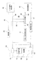
図2を参照して、前記測定装置本体2の概略構成を説明する。
With reference to FIG. 2, a schematic configuration of the measurement apparatus
該測定装置本体2は、主に前記水平モータ19、前記撮像部30、前記測距部25、前記発光部27、前記演算制御部35、角度測定部36、記憶部37、操作部38等から構成されている。
The measuring apparatus
更に、前記演算制御部35は、クロック信号発生部41、トリガ信号発生部42、角度演算部43、カウンタ回路44を含んでいる。前記角度測定部36は、前記水平角エンコーダ14、前記鉛直角エンコーダ33を含み、前記測距光31の照射方向(方向角)を検出する。
Further, the
前記記憶部37は、プログラム格納領域、データ格納領域を有し、前記プログラム格納領域には、前記測定装置本体2に一連の測定作動を実行させる為の測距プログラム、前記撮像素子24から発せられる信号を画像信号に処理し、画像データとして前記記憶部37に格納する画像処理プログラム、前記角度測定部36から入力される角度信号に基づき回転角度を演算する測角プログラム等のプログラムが格納されている。
The
前記演算制御部35は、前記測距プログラム、前記測角プログラム等のプログラムに基づき、前記水平モータ19の等速回転制御、前記鉛直モータ20の等速回転制御、前記発光部27のパルス発光制御を行い、前記測距受光素子28の受光信号に基づき距離を演算し、前記撮像素子24による撮像の制御、前記水平角エンコーダ14、前記鉛直角エンコーダ33からの信号による回転角度の検出の制御、測角等を行う。
The
次に、上記レーザスキャナ1による測定作動について説明する。
Next, the measurement operation by the
前記操作部38により測定範囲を設定する。測定範囲が設定された後、測距作動が実行される。又、前記演算制御部35により、前記水平モータ19、前記鉛直モータ20がそれぞれ所定の速度で等速回転される。
The measurement range is set by the
前記演算制御部35より前記測距部25に対して測距の為の制御信号が発せられる。前記発光部27が駆動され、パルス光の前記測距光31が発せられる。該測距光31が前記光学系32、前記偏向ミラー13を介して射出される。
A control signal for distance measurement is issued from the
測定対象物で反射された前記反射測距光31aを、前記偏向ミラー13、前記光学系32を介して受光し、受光を検出して測定対象物迄の距離を算出する(測距)。又、受光検出時に於ける方向角(水平角、鉛直角)を、前記角度測定部36からの信号に基づき演算する(測角)。従って、算出した距離、照射方向の角度を測定することで測定点の3次元座標が取得できる。
The reflected distance measuring light 31a reflected from the measurement object is received through the
更に、パルス発光させつつ、前記水平モータ19によって、前記回転部12を等速で水平回転させ、更に前記鉛直モータ20によって、前記偏向ミラー13を等速で鉛直方向に回転させる。パルス光が測定範囲に走査される。パルス光毎に、距離のデータ、方向角を測定することで、測距、測角データを有する点群データを取得できる。
Further, while rotating the pulse, the
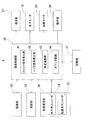
次に、高速で水平角、鉛直角を測定する場合について、図3、図4を参照して説明する。 Next, the case of measuring the horizontal angle and the vertical angle at high speed will be described with reference to FIGS.
前記角度測定部36は、前記水平角エンコーダ14から出力される信号により水平角を検出し、前記鉛直角エンコーダ33から出力される信号によって鉛直角を検出する。尚、前記水平角エンコーダ14、前記鉛直角エンコーダ33は同様の構成であり、又同様の処理で角度を検出するので、以下は、高速回転する前記偏向ミラー13の鉛直回転角度を検出する前記鉛直角エンコーダ33について説明する。
The
該鉛直角エンコーダ33は、回転側に設けられた目盛円盤15と、固定側に設けられた検出部16とを有する。
The
該検出部16は照明光を発する発光素子51と、前記目盛円盤15に対峙して設けられた走査盤52と、イメージセンサ53とを有する。前記走査盤52には、前記目盛円盤15のパターンを角度として読取る為のパターンが設けられている。前記イメージセンサ53は、前記目盛円盤15、前記走査盤52を透過した照明光をパターン画像として受光する様になっている。
The
以下、高速回転時の角度検出について説明する。尚、前記偏向ミラー13は等速回転する様制御されている。
Hereinafter, angle detection during high-speed rotation will be described. The
前記トリガ信号発生部42から前記測距部25に、制御信号55が入力され、前記測距部25からは前記偏向ミラー13を経て前記測距光31が照射され、前記測距部25は測定対象物で反射された、前記反射測距光31aを受光して測距を行う。
A
又、前記トリガ信号発生部42から、所定時間間隔(等時間間隔)で角度検出用の角度トリガ信号56が前記鉛直角エンコーダ33に入力される。
Further, an
該鉛直角エンコーダ33は、前記角度トリガ信号56が入力される度に前記発光素子51を発光させ、前記イメージセンサ53により前記角度トリガ信号56入力時のパターン画像を取得し、角度検出部45に出力する。該角度検出部45はパターン画像より、回転角度を検出する。パターン画像より得られる角度は、基準位置(例えば、前記操作部38で設定した基準位置)からの絶対角度となる。
The
従って、前記目盛円盤15が等速回転し、前記角度トリガ信号56が等時間間隔で入力されると、前記角度検出部45で検出する回転角度は、等角度間隔で得られる。又、前記角度トリガ信号56が発せられる時間間隔を、前記角度検出部45が角度検出する速度より大きく設定しておけば、前記目盛円盤15が高速回転していても、角度検出は支障なく実行される。
Accordingly, when the
前記角度検出部45で検出された角度は、主検出角度57として前記角度演算部43に入力される。尚、前記角度検出部45の機能を前記角度演算部43に実行させ、前記角度検出部45は省略してもよい。
The angle detected by the
次に、前記クロック信号発生部41から発生されるクロック信号が前記カウンタ回路44に入力され、クロック信号がカウントされる。前記トリガ信号発生部42から前記角度トリガ信号56が前記カウンタ回路44に入力され、前記角度トリガ信号56が入力される度にカウント値がリセットされる。
Next, the clock signal generated from the
又、前記測距部25からは、前記反射測距光31aを受光した時点に発せられる受光検出信号58が前記カウンタ回路44に入力される。
From the
該カウンタ回路44は、前記受光検出信号58が入力された時点迄のクロック信号のカウント数をカウント信号59として前記角度演算部43に入力する。該角度演算部43は、前記角度検出部45からの前記主検出角度57と前記カウント信号59とにより測距時(前記反射測距光31a受光時)の回転角度を演算する。尚、前記角度検出部45から出力される前記主検出角度57は、前記受光検出信号58が入力される前後が保存されていればよく、前記受光検出信号58が入力されない場合は、順次消去してもよい。
The
該受光検出信号58は、受光時の回転角度を検出する為の信号であり、回転角測定トリガ信号としての機能を有する。
The light
図4を参照して、更に説明する。 Further description will be given with reference to FIG.
前記角度トリガ信号56が発せられた時刻をti とし、次に該角度トリガ信号56が発せられた時刻をti+1 とする。又、前記受光検出信号58が発せられる時刻をtj とし、tj はti とti+1 との間に発せられたとする(ti <tj <ti+1 )。
The time when the
又、時刻ti での主検出角度をφi 、時刻ti+1 での主検出角度をφ(ti+1 )、測距時の角度をθとする。 The main detection angle at time ti is φi, the main detection angle at time ti + 1 is φ (ti + 1), and the angle at the time of distance measurement is θ.
時刻ti から前記受光検出信号58が発せられる迄の時間は、クロック信号のカウント数で取得でき、該クロック信号のカウント数から時刻tj を演算できる。
The time from the time ti until the light
時刻ti での主検出角度φi と時刻ti+1 での主検出角度φ(ti+1 )は、前記角度検出部45によって検出される。更に、等速回転であるので、時刻tj (測距時)からの回転角度は、主検出角度φi と主検出角度φ(ti+1 )との差を時間で案分することで得られる。
The main detection angle φi at time ti and the main detection angle φ (ti + 1) at time ti + 1 are detected by the
従って、測距時の回転角度θは、
θ=[(tj −ti )/((ti+1 )−ti )]×(φ(i+1 )−φi )+φi で得られる。
Therefore, the rotation angle θ during distance measurement is
.theta. = [(tj-ti) / ((ti + 1) -ti)]. times. (. phi. (i + 1)-. phi.i) +. phi.i.
而して、前記鉛直角エンコーダ33自体の検出速度が遅くとも、高速回転時の回転角度の測定が可能となり、レーザスキャナとして高速で回転しつつ点群データの取得を可能とする。
Thus, even if the detection speed of the
次に、高速回転していない場合、即ち、アブソリュートエンコーダの角度検出速度より遅い回転速度(アブソリュートエンコーダの角度検出応答速度より遅い回転速度)の場合、或は停止して測定点の測定を行う場合の回転角度の測定は、前記水平角エンコーダ14、前記鉛直角エンコーダ33の検出速度は問題とならないので、アブソリュートエンコーダの通常の角度検出作動でよい。即ち、前記イメージセンサ53からの画像信号に基づき、高精度の測定が行える。
Next, when not rotating at high speed, that is, when the rotation speed is slower than the absolute encoder angle detection speed (rotation speed slower than the absolute encoder angle detection response speed), or when stopping and measuring the measurement point In the measurement of the rotation angle, since the detection speeds of the
本実施例では、アブソリュートエンコーダを用いて複雑な信号処理を行うことなく、クロック信号をカウントするだけの簡単な処理で高精度の回転角度検出を行うことができる。 In this embodiment, high-accuracy rotation angle detection can be performed by simple processing that simply counts clock signals without performing complicated signal processing using an absolute encoder.
又、本発明の角度検出装置は、測量装置だけでなく、等速回転する機器の角度検出装置として使用できることは言う迄もない。 Needless to say, the angle detection device of the present invention can be used not only as a surveying device but also as an angle detection device for equipment rotating at a constant speed.
1 レーザスキャナ
2 測定装置本体
12 回転部
13 偏向ミラー
14 水平角エンコーダ
16 検出部
19 水平モータ
20 鉛直モータ
24 撮像素子
25 測距部
27 発光部
28 測距受光素子
33 鉛直角エンコーダ
35 演算制御部
36 角度測定部
41 クロック信号発生部
42 トリガ信号発生部
43 角度演算部
44 カウンタ回路
45 角度検出部
51 発光素子
52 走査盤
55 制御信号
56 角度トリガ信号
57 主検出角度
58 受光検出信号
59 カウント信号
DESCRIPTION OF
Claims (3)
Priority Applications (2)
| Application Number | Priority Date | Filing Date | Title |
|---|---|---|---|
| JP2015238381A JP6767107B2 (en) | 2015-12-07 | 2015-12-07 | Angle detector and surveying device |
| US15/361,703 US10267659B2 (en) | 2015-12-07 | 2016-11-28 | Angle detecting device and surveying instrument |
Applications Claiming Priority (1)
| Application Number | Priority Date | Filing Date | Title |
|---|---|---|---|
| JP2015238381A JP6767107B2 (en) | 2015-12-07 | 2015-12-07 | Angle detector and surveying device |
Publications (2)
| Publication Number | Publication Date |
|---|---|
| JP2017106730A true JP2017106730A (en) | 2017-06-15 |
| JP6767107B2 JP6767107B2 (en) | 2020-10-14 |
Family
ID=58798343
Family Applications (1)
| Application Number | Title | Priority Date | Filing Date |
|---|---|---|---|
| JP2015238381A Active JP6767107B2 (en) | 2015-12-07 | 2015-12-07 | Angle detector and surveying device |
Country Status (2)
| Country | Link |
|---|---|
| US (1) | US10267659B2 (en) |
| JP (1) | JP6767107B2 (en) |
Families Citing this family (6)
| Publication number | Priority date | Publication date | Assignee | Title |
|---|---|---|---|---|
| JP6650726B2 (en) * | 2015-10-20 | 2020-02-19 | 株式会社トプコン | measuring device |
| JP6650727B2 (en) | 2015-10-20 | 2020-02-19 | 株式会社トプコン | Tilt angle measuring device |
| JP6691419B2 (en) * | 2016-04-15 | 2020-04-28 | 株式会社トプコン | Control method of ultrasonic motor and surveying instrument therefor |
| EP3835817A1 (en) * | 2018-05-16 | 2021-06-16 | Miele & Cie. KG | 3d scanning lidar sensor |
| CN113970752A (en) * | 2020-07-22 | 2022-01-25 | 商汤集团有限公司 | Target detection method and device, electronic equipment and storage medium |
| CN117249846B (en) * | 2023-11-17 | 2024-02-09 | 浙江明哲电子科技有限公司 | Encoder pre-decoding processing method, system and storage medium |
Citations (4)
| Publication number | Priority date | Publication date | Assignee | Title |
|---|---|---|---|---|
| JP2004513357A (en) * | 2000-10-31 | 2004-04-30 | ドクトル・ヨハネス・ハイデンハイン・ゲゼルシヤフト・ミツト・ベシユレンクテル・ハフツング | Position measuring apparatus and position measuring method |
| JP2008032562A (en) * | 2006-07-28 | 2008-02-14 | Ntn Corp | Rotation detector, and bearing with rotation detector |
| JP2012068243A (en) * | 2010-09-24 | 2012-04-05 | Sick Ag | Laser scanner and manufacturing method thereof |
| JP2012093245A (en) * | 2010-10-27 | 2012-05-17 | Topcon Corp | Laser surveying instrument |
Family Cites Families (4)
| Publication number | Priority date | Publication date | Assignee | Title |
|---|---|---|---|---|
| JPS60157014A (en) | 1984-01-26 | 1985-08-17 | Tokyo Optical Co Ltd | Method and device for interpolating encoder read signal |
| JP3700325B2 (en) * | 1997-05-21 | 2005-09-28 | 松下電器産業株式会社 | Drive source control method |
| US7215808B2 (en) * | 2004-05-04 | 2007-05-08 | Kla-Tencor Technologies Corporation | High throughout image for processing inspection images |
| DE102006009773A1 (en) * | 2006-03-01 | 2007-09-06 | Eastman Kodak Co. | Method for avoiding a registration error during printing |
-
2015
- 2015-12-07 JP JP2015238381A patent/JP6767107B2/en active Active
-
2016
- 2016-11-28 US US15/361,703 patent/US10267659B2/en active Active
Patent Citations (4)
| Publication number | Priority date | Publication date | Assignee | Title |
|---|---|---|---|---|
| JP2004513357A (en) * | 2000-10-31 | 2004-04-30 | ドクトル・ヨハネス・ハイデンハイン・ゲゼルシヤフト・ミツト・ベシユレンクテル・ハフツング | Position measuring apparatus and position measuring method |
| JP2008032562A (en) * | 2006-07-28 | 2008-02-14 | Ntn Corp | Rotation detector, and bearing with rotation detector |
| JP2012068243A (en) * | 2010-09-24 | 2012-04-05 | Sick Ag | Laser scanner and manufacturing method thereof |
| JP2012093245A (en) * | 2010-10-27 | 2012-05-17 | Topcon Corp | Laser surveying instrument |
Also Published As
| Publication number | Publication date |
|---|---|
| JP6767107B2 (en) | 2020-10-14 |
| US10267659B2 (en) | 2019-04-23 |
| US20170160108A1 (en) | 2017-06-08 |
Similar Documents
| Publication | Publication Date | Title |
|---|---|---|
| JP6767107B2 (en) | Angle detector and surveying device | |
| US11650291B2 (en) | LiDAR sensor | |
| JP2017223540A (en) | Measuring system | |
| JP2017096629A (en) | Measurement device | |
| US9759583B2 (en) | Method of obtaining a reference correction value for an index mark of an angular encoder | |
| JP6347674B2 (en) | Laser scanner system | |
| JP2018132328A (en) | Measuring instrument | |
| JP2022000645A (en) | Laser scanner | |
| US11789151B2 (en) | Target unit | |
| JP2017223541A (en) | Laser scanner | |
| JP6640541B2 (en) | Laser scanner | |
| US11629959B2 (en) | Surveying instrument | |
| JP6253932B2 (en) | Direction detection device and survey system | |
| US11635490B2 (en) | Surveying system having a rotating mirror | |
| JP2005292037A (en) | Angle measuring instrument | |
| JP2018048868A (en) | Scanner device and surveying device | |
| JP6749191B2 (en) | Scanner and surveying equipment | |
| JP5213607B2 (en) | Substrate surface displacement measuring device | |
| JP2020056615A (en) | Surveying system, surveying instrument, and surveying method | |
| EP4160145A1 (en) | Surveying instrument | |
| CN115685140A (en) | Measuring device | |
| JP2008256463A (en) | Measurement apparatus and miller attitude rotation and monitoring apparatus | |
| JP2018163029A (en) | Measurement device, and survey system |
Legal Events
| Date | Code | Title | Description |
|---|---|---|---|
| A621 | Written request for application examination |
Free format text: JAPANESE INTERMEDIATE CODE: A621 Effective date: 20181029 |
|
| A977 | Report on retrieval |
Free format text: JAPANESE INTERMEDIATE CODE: A971007 Effective date: 20190926 |
|
| A131 | Notification of reasons for refusal |
Free format text: JAPANESE INTERMEDIATE CODE: A131 Effective date: 20191001 |
|
| A521 | Request for written amendment filed |
Free format text: JAPANESE INTERMEDIATE CODE: A523 Effective date: 20191112 |
|
| A131 | Notification of reasons for refusal |
Free format text: JAPANESE INTERMEDIATE CODE: A131 Effective date: 20200421 |
|
| A521 | Request for written amendment filed |
Free format text: JAPANESE INTERMEDIATE CODE: A523 Effective date: 20200604 |
|
| TRDD | Decision of grant or rejection written | ||
| A01 | Written decision to grant a patent or to grant a registration (utility model) |
Free format text: JAPANESE INTERMEDIATE CODE: A01 Effective date: 20200908 |
|
| A61 | First payment of annual fees (during grant procedure) |
Free format text: JAPANESE INTERMEDIATE CODE: A61 Effective date: 20200917 |
|
| R150 | Certificate of patent or registration of utility model |
Ref document number: 6767107 Country of ref document: JP Free format text: JAPANESE INTERMEDIATE CODE: R150 |
|
| R250 | Receipt of annual fees |
Free format text: JAPANESE INTERMEDIATE CODE: R250 |