JP2017105393A - Cooling system - Google Patents
Cooling system Download PDFInfo
- Publication number
- JP2017105393A JP2017105393A JP2015242196A JP2015242196A JP2017105393A JP 2017105393 A JP2017105393 A JP 2017105393A JP 2015242196 A JP2015242196 A JP 2015242196A JP 2015242196 A JP2015242196 A JP 2015242196A JP 2017105393 A JP2017105393 A JP 2017105393A
- Authority
- JP
- Japan
- Prior art keywords
- heat exchanger
- radiator
- cooling device
- air
- vehicle
- Prior art date
- Legal status (The legal status is an assumption and is not a legal conclusion. Google has not performed a legal analysis and makes no representation as to the accuracy of the status listed.)
- Granted
Links
- 238000001816 cooling Methods 0.000 title claims abstract description 66
- 238000009423 ventilation Methods 0.000 claims abstract description 26
- 238000004378 air conditioning Methods 0.000 claims description 79
- 238000005192 partition Methods 0.000 claims description 11
- 239000003990 capacitor Substances 0.000 description 38
- 239000003507 refrigerant Substances 0.000 description 18
- 239000002826 coolant Substances 0.000 description 8
- 230000000903 blocking effect Effects 0.000 description 1
- 239000000498 cooling water Substances 0.000 description 1
- 230000000694 effects Effects 0.000 description 1
- 238000005516 engineering process Methods 0.000 description 1
- 230000005484 gravity Effects 0.000 description 1
- 230000004048 modification Effects 0.000 description 1
- 238000012986 modification Methods 0.000 description 1
- XLYOFNOQVPJJNP-UHFFFAOYSA-N water Substances O XLYOFNOQVPJJNP-UHFFFAOYSA-N 0.000 description 1
Images
Abstract
Description
本発明は、冷却装置に係り、特に、複数の熱交換器と送風機および送風機シュラウドとを有するものに関する。 The present invention relates to a cooling device, and more particularly, to a cooling device having a plurality of heat exchangers, a blower, and a blower shroud.
従来、図3で示すような冷却装置301が知られている。冷却装置301は、たとえば車両303に搭載されており、空調用コンデンサ305とサブラジエータ307とラジエータ309とを備えている。また、冷却装置301には、シュラウド311とファン313とが設けられている。
Conventionally, a
そして、車両303が走行しているときには、走行風が、空調用コンデンサ305とラジエータ309(ラジエータ309の上側の部位)とを通過し、また、サブラジエータ307とラジエータ309(ラジエータ309の下側の部位)とを通過することで、空調用コンデンサ305の冷媒とサブラジエータ307の冷媒とラジエータ309の冷媒とが、冷却されるようになっている。
When the
また、車両303が停車しているとき(アイドル状態にあるとき)等には、ファン303によって生成された空気流が、空調用コンデンサ305とラジエータ309(ラジエータ309の上側の部位)とを通過し、空調用コンデンサ305の冷媒とラジエータ309の冷媒とが、冷却されるようになっている。
In addition, when the
なお、従来の技術に関連する文献として、たとえば、特許文献1を掲げることができる。
For example,
従来の熱交換器301では、車両303の走行状態に応じて、空調用コンデンサ305とサブラジエータ307とを効率良く冷却することができないことがおきるおそれがあるという問題がある。
The
さらに説明すると、車両303の走行状態にかかわらず空調用コンデンサ305の能力が足りている一方、車両303が高速走行している場合等において、サブラジエータ307の能力が不足する場合がある。
More specifically, while the capacity of the
すなわち、車両303がアイドル状態にある場合等、車両303の走行風による冷却が十分にできない状態で、ファン313が稼働する。この稼働によって、空調用コンデンサ305は十分に冷却される。なお、車両303がアイドル状態にある場合等、車両303が高速走行していない状態では、サブラジエータ307の冷却は、ほとんど必要とされない場合が多い。
That is, when the
一方、車両303が高速走行している状態では、図3に矢印A301,矢印A302で示す空気の流れが発生し、空調用コンデンサ305の冷媒とサブラジエータ307の冷媒とが冷却される。
On the other hand, when the
しかし、車両303が高速走行している場合、サブラジエータ307を一層冷却することが必要な場合があり、これに対応することができない場合があるおそれがある。
However, when the
上記問題点に鑑みてなされたものであり、複数の熱交換器と送風機とを備えた冷却装置において、車両の走行状態にかかわらず、各熱交換器を効率良く冷却することができるとともに、特に、走行風による冷却がなされる状態にあって、複数の熱交換器のうちで冷却を必要としている熱交換器を十分に冷却することができる冷却装置を提供することを目的とする。 In view of the above problems, in a cooling device including a plurality of heat exchangers and a blower, each heat exchanger can be efficiently cooled regardless of the running state of the vehicle, and in particular An object of the present invention is to provide a cooling device that can sufficiently cool a heat exchanger that needs to be cooled among a plurality of heat exchangers in a state where cooling by running wind is performed.
本発明は、第1の熱交換器と、車両前後方向で前記第1の熱交換器と並列にならんで設けられ、通気抵抗が前記第1の熱交換器よりも小さい第2の熱交換器と、車両前後方向で前記第1の熱交換器および前記第2の熱交換器の後方に、前記第1の熱交換器および前記第2の熱交換器と直列にならんで設けられた第3の熱交換器と、車両前後方向で前記第3の熱交換器の後方に設けられている送風機およびシュラウドとを有する冷却装置である。 The present invention provides a first heat exchanger and a second heat exchanger that is provided in parallel with the first heat exchanger in the longitudinal direction of the vehicle and has a smaller airflow resistance than the first heat exchanger. And a third side provided in series with the first heat exchanger and the second heat exchanger behind the first heat exchanger and the second heat exchanger in the longitudinal direction of the vehicle. And a blower and a shroud provided behind the third heat exchanger in the vehicle front-rear direction.
本発明によれば、複数の熱交換器と送風機とを備えた冷却装置において、車両の走行状態にかかわらず、各熱交換器を効率良く冷却することができるとともに、特に、走行風による冷却がなされる状態にあって、複数の熱交換器のうちで冷却を必要としている熱交換器を十分に冷却することができる冷却装置を提供することができるという効果を奏する。 According to the present invention, in a cooling device including a plurality of heat exchangers and a blower, each heat exchanger can be efficiently cooled regardless of the traveling state of the vehicle. There is an effect that it is possible to provide a cooling device that can sufficiently cool a heat exchanger that needs to be cooled among a plurality of heat exchangers.
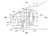
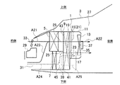
本発明の実施形態に係る冷却装置1は、たとえば、図1や図2に示すように、自動車等の車両3に搭載(設置)されて使用されるものであり、冷却装置1の冷媒を冷やす空気流は、概ね車両3の前側から後側に向かって流れるようになっている。
The
冷却装置1は、第1の熱交換器(たとえば、空調用コンデンサ)5と、第2の熱交換器(たとえば、サブラジエータ)7と、第3の熱交換器(たとえば、ラジエータ)9と、シュラウド11と、送風機(ファン)13とを備えて構成されている。
The
サブラジエータ7は、空気の流れ方向である車両前後方向で、空調用コンデンサ5と並列にならんで設けられている。また、サブラジエータ7の通気抵抗と空調用コンデンサ5の通気抵抗とはお互いが異なっている。ここでは、サブラジエータ7の通気抵抗は、空調用コンデンサ5の通気抵抗よりも小さくなっている。
The
ラジエータ9は、車両前後方向で、空調用コンデンサ5およびサブラジエータ7の後方に、空調用コンデンサ5およびサブラジエータ7と直列にならんで設けられている。なお、空調用コンデンサ5およびサブラジエータ7と、ラジエータ9との間は、所定の間隔があいている。
The radiator 9 is provided behind the
シュラウド11は、車両前後方向で、ラジエータ9の後方に設けられている。送風機13は、空気流を生成するために設けられている。
The
車両の前側から後側に向かって見たときに、ラジエータ9は、空調用コンデンサ5と重なっている第1熱交換器重なり部位(空調用コンデンサ重なり部位)15と、サブラジエータ7と重なっている第2熱交換器重なり部位(サブラジエータ重なり部位)17とを備えている。
When viewed from the front side toward the rear side of the vehicle, the radiator 9 overlaps the first heat exchanger overlapping portion (air-conditioning capacitor overlapping portion) 15 that overlaps the air-
さらに説明すると、車両の前側から後側に向かって見たときに、空調用コンデンサ5は、車両上下方向でラジエータ9よりも小さくなっており、ラジエータ9の内側に存在している。また、車両の前側から後側に向かって見たときに、サブラジエータ7も、ラジエータ9より小さくなっている。
More specifically, when viewed from the front side to the rear side of the vehicle, the
空調用コンデンサ5は、サブラジエータ7の上方に位置している。ラジエータ9を所定の境界線(たとえば、水平方向に延伸している直線状の境界線)で2つの部位に分けると、一方の部位(たとえば、上側の部位)に空調用コンデンサ5が重なっていることで一方の部位が第1熱交換器重なり部位15になっており、他方の部位(たとえば、下側の部位)にサブラジエータ7が重なっていることで他方の部位が第2熱交換器重なり部位17になっている。
The
また、車両の前側から後側に向かって見たときに、シュラウド11の前側の開口部19が第1熱交換器重なり部位15の総てと、第2熱交換器重なり部位17の一部とに重なっている。
Further, when viewed from the front side of the vehicle toward the rear side, the opening 19 on the front side of the
さらに、車両の前側から後側に向かって見たときに、第1熱交換器重なり部位15と、シュラウドの前側の開口部19との重なり部位21の面積が、第2熱交換器重なり部位17と、シュラウドの前側の開口部19との重なり部位23の面積よりも大きくなっている。尚、本実施の形態では、開口部19との重なり部位21の面積が、開口部19との重なり部位23の面積よりも大きいが、重なり部位21,23の面積の大小はこの限りではなく、変形例として、重なり部位21,23の面積がほぼ等しい場合や、重なり部位21の面積が重なり部位23の面積より小さい場合もある。
Further, when viewed from the front side to the rear side of the vehicle, the area of the overlapping
冷却装置1では、たとえば、サブラジエータ7の厚さ(車両前後方向の寸法)が、空調用コンデンサ5の厚さ(車両前後方向の寸法)よりも薄くなっていることで、サブラジエータ7の通気抵抗が空調用コンデンサ5の通気抵抗よりも小さくなっている。
In the
また、冷却装置1には、空調用コンデンサ5と、サブラジエータ7との間での空気の流れを遮断するための仕切り板25が設けられている。
The
ここで、冷却装置1についてさらに詳しく説明する。
Here, the
冷却装置1では、車両3が停車している等、車両3の走行風による冷却が期待できない場合であっても、送風機13を稼働することで、空気が各熱交換器5,7,9を通過するようになっている。
In the
ここで、上述した通気抵抗について詳しく説明する。各熱交換器5,7,9はこれらの厚さ方向が前後方向になっており、空気は、各熱交換器5,7,9の厚さ方向で各熱交換器5,7,9のそれぞれを通過するようになっている。車両の前側から後側に向かって見たときに、各熱交換器5,7,9は、それぞれが所定の面積を有している。
Here, the ventilation resistance described above will be described in detail. The
熱交換器5(7,9)における抵抗係数ξ(グザイ)は、熱交換器5(7,9)における空気の流れ易さを示す値であり、式(ΔP=1/2・ξ(Q/A)2ρ)で表される。 The resistance coefficient ξ (Guzai) in the heat exchanger 5 (7, 9) is a value indicating the ease of air flow in the heat exchanger 5 (7, 9), and is expressed by the equation (ΔP = 1/2 · ξ (Q / A) 2 ρ).
上式におけるΔPは、熱交換器5(7,9)における空気の圧力損失を示しており、空気の流れ方向で熱交換器5(7,9)の直前における空気の圧力と、熱交換器5(7,9)の直後における空気の圧力との差である。 ΔP in the above equation indicates the pressure loss of air in the heat exchanger 5 (7, 9). The air pressure immediately before the heat exchanger 5 (7, 9) in the air flow direction and the heat exchanger This is the difference from the air pressure immediately after 5 (7, 9).
上記式におけるQは、熱交換器5(7,9)を通過する空気流量(単位時間あたりの体積)であり、上記式におけるAは、熱交換器5(7,9)の面積(前側から後側に向かって見たときの面積)であり、上記式におけるρは、空気の密度である。 Q in the above formula is the air flow rate (volume per unit time) passing through the heat exchanger 5 (7, 9), and A in the above formula is the area (from the front side) of the heat exchanger 5 (7, 9). Area when viewed toward the rear side), and ρ in the above equation is the density of air.
上記式から明らかなように、抵抗係数ξは、各熱交換器5,7,9それぞれにおける固有の抵抗係数ということになる。換言すれば、抵抗係数ξは、熱交換器5(7,9)の単位面積あたりの通気抵抗もしくは単位風量あたりの通気抵抗と言える。
As is clear from the above equation, the resistance coefficient ξ is a specific resistance coefficient in each of the
また、各熱交換器5,7,9のそれぞれは、内部を水等の冷却媒体が流れる複数本のチューブと、薄く細長い平板状に形成されている複数枚(多数)のフィンとを備えて構成されている。各チューブは、たとえば、上下方向で所定の間隔をあけて左右方向に延びている。多数のフィンは、厚さ方向がチューブの延伸方向で一致し、幅方向が前後方向になるようにして、たとえば、左右方向で所定の間隔をあけて上記チューブと直交する方向(たとえば、上下方向)に延びて上記チューブと一体化している。
Each of the
熱交換器5(7,9)の通気抵抗は、チューブやフィンの形態で決まる。すなわち、熱交換器5(7,9)の通気抵抗は、チューブの外形やチューブのピッチやフィンの形状やフィンのピッチで決まる。 The ventilation resistance of the heat exchanger 5 (7, 9) is determined by the form of tubes and fins. That is, the ventilation resistance of the heat exchanger 5 (7, 9) is determined by the outer shape of the tube, the pitch of the tube, the shape of the fin, and the pitch of the fin.
たとえば、空調用コンデンサ5と、サブラジエータ7とにおいて、チューブの外形、チューブのピッチ、幅寸法を除くフィンの形状、フィンのピッチを同一として考えた場合、サブラジエータ7のフィンの幅(サブラジエータ7の厚さ)を、空調用コンデンサ5のフィンの幅(空調用コンデンサ5の厚さ)よりも小さくすることで、サブラジエータ7の通気抵抗が空調用コンデンサ5の通気抵抗よりも小さくなる。
For example, in the air-
冷却装置1は、車両3のエンジンルーム27内の前方に搭載されている。エンジンルーム27内の後方には車両3を駆動するエンジンが搭載されている。車両3の前部には、バンパー29が設けられており、バンパー29の下側にはロアグリル31が設けられており、上側にはアッパグリル33が設けられている。
The
そして、ロアグリル31やアッパグリル33から空気がエンジンルーム27内に入り、冷却空気として冷却装置1を通過し、エンジンに至るようになっている。エンジンルーム27内に入った空気は、エンジンルーム27の、たとえば、下側から車両3の外部に出ていくようになっている。
Air enters the
空調用コンデンサ5は、たとえば、矩形な板状に形成されている。冷却装置1が車両3に設置された状態では、空調用コンデンサ5の厚さ方向が車両3の前後方向になっており、空調用コンデンサ5のチューブ内を流れる冷却媒体が、空調用コンデンサ5のフィンと、チューブとの間隙を通過して車両3の前側から後側に向かって流れる空気によって、冷却されるようになっている。
The
サブラジエータ7も、たとえば、矩形な板状に形成されている。冷却装置1が車両3に設置された状態では、サブラジエータ7の厚さ方向が車両3の前後方向になっており、サブラジエータ7のチューブ内を流れる冷却媒体が、サブラジエータ7のフィンと、チューブとの間隙を通過して車両3の前側から後側に向かって流れる空気によって、冷却されるようになっている。
The
また、空調用コンデンサ5の下方に、サブラジエータ7が設けられており、車両上下方向で、空調用コンデンサ5の下端の位置と、サブラジエータ7の上端の位置とがお互いにほぼ一致している。
A
ラジエータ9も、空調用コンデンサ5と同様に、チューブと、フィンとを備えて、たとえば、矩形な板状に形成されている。冷却装置1が車両3に設置された状態では、ラジエータ9の厚さ方向が車両3の前後方向になっており、空調用コンデンサ5と、サブラジエータ7とを通ってきた空気(フィンと、チューブとの間隙を通過した空気)が、ラジエータ9のフィンと、チューブとの間隙を通過して車両3の前側から後側に向かって流れ、この空気によって、ラジエータのチューブ内を流れる冷却媒体が冷却されるようになっている。
Similarly to the air-
また、車両の前側から後側に向かって見ると、空調用コンデンサ5の総ておよびサブラジエータ7の総てに、ラジエータ9が重なっている。
Further, when viewed from the front side to the rear side of the vehicle, the radiator 9 overlaps all of the
シュラウド11は、ラジエータ9の後側に設けられている。冷却装置1が車両に設置された状態では、空気が、シュラウド11の前側の開口部19から、シュラウド11の後側の開口部に向かって、シュラウド11内を流れるようになっている。シュラウド11の前端の開口部19は、ラジエータ9の後面に接しているか、もしくは、僅かに離れている。
The
シュラウド11の前側の開口部19は、矩形状に形成されている。車両の前側から後側に向かって見ると、前側の開口部19は空調用コンデンサ5の総てと、サブラジエータ7の上側の部位とに重なっている。また、車両の前側から後側に向かって見ると、前側の開口部19の総てが、ラジエータ9の上側の矩形状の部位(第1熱交換器重なり部位15および第2熱交換器重なり部位23)に重なっている。
The
送風機13は、回転することで空気の流れを発生する羽根35と、この羽根35を回転させるモータ37とを備えて構成されている。また、送風機13は、シュラウド11の後方に設置されている。
The
仕切り板25は、矩形な薄い板状に形成されており、厚さ方向が車両の上下方向になって、空調用コンデンサ5およびサブラジエータ7と、ラジエータ9との間の空間39に設置されている。
The
車両の横方向で、仕切り板25の左端は、空調用コンデンサ5、およびラジエータ9の左端と一致しており、仕切り板25の右端は、空調用コンデンサ5、およびラジエータ9の右端と一致している。
In the lateral direction of the vehicle, the left end of the
車両の前後方向で、仕切り板25の前端の全長(図1、図2の紙面に直交する方向の寸法における全長)は、空調用コンデンサ5と、サブラジエータ7との境界の全長に接しており、仕切り板25の後端の全長は、ラジエータ9の前面41に接している。
In the longitudinal direction of the vehicle, the total length of the front end of the partition plate 25 (the total length in the direction perpendicular to the plane of FIG. 1 and FIG. 2) is in contact with the total length of the boundary between the
これにより、空調用コンデンサ5およびサブラジエータ7と、ラジエータ9との間の空間39が、上側の空間43と、下側の空間45とに仕切られている。上側の空間43では、空調用コンデンサ5を通過した空気がラジエータ9の上側の部位(第1熱交換器重なり部位15)に向かって流れ、下側の空間45では、サブラジエータ7を通過した空気がラジエータ9の下側の部位(第2熱交換器重なり部位17)に向かって流れるようになっている。
As a result, the
仕切り板25によって、空調用コンデンサ5を通過した空気と、サブラジエータ7を通過した空気とが、ラジエータ9に到達する前にお互いが遮断され、お互いが混じり合わないようになっている。
The
なお、図1、図2では、仕切り板25の後端が、ラジエータ9の前面41のところに位置しているが、仕切り板25の後端が、ラジエータ9のフィンを突きって、ラジエータ9の後面まで延びていてもよいし、さらに、ラジエータ9の後面からシュラウド11内に延びていてもよい。
1 and 2, the rear end of the
なお、ラジエータ9は、車両3のエンジンの冷却水(冷却媒体)を冷却するものであり、空調用コンデンサ5は、車両3のキャビン内の空調をするエアコンディショナーの冷媒を冷却するものである。また、サブラジエータ7として、水冷チャージエアクーラの放熱器、電気機器の冷却器の放熱器等を掲げることができる。
The radiator 9 cools cooling water (cooling medium) of the engine of the
次に、冷却装置1の動作を説明する。
Next, the operation of the
車両3がアイドル状態等になっていることで走行風がほとんど発生していない場合、送風機13が稼働することで羽根35が回転する。
When the traveling wind is hardly generated because the
そして、図2に示すように、主としてアッパグリル33からエンジンルーム27内に入った空気が、空調用コンデンサ5と、ラジエータ9の上部と、シュラウド11内をこの順に流れ(図2の矢印A21、A22参照)、空調用コンデンサ5と、ラジエータ9とが冷却される。
As shown in FIG. 2, the air that mainly enters the
また、主としてロアグリル31からエンジンルーム27内に入った空気が、空調用コンデンサ5と、ラジエータ9の上部と、シュラウド11内をこの順に流れ(図2の矢印A23、A22参照)、空調用コンデンサ5と、ラジエータ9とが冷却される。
Also, air that has entered the
また、主としてロアグリル31からエンジンルーム27内に入った空気が、サブラジエータ7と、ラジエータ9の下部17のうちの上側部位23と、シュラウド11内をこの順に流れ(図2の矢印A24参照)、サブラジエータ7と、ラジエータ9とが冷却される。
In addition, air that has entered the
なお、空調用コンデンサ5の通気抵抗がサブラジエータ7の通気抵抗がよりも大きくなっていること等により、図2に矢印A23で示す空気の流れは、図2に矢印A24で示す空気の流れよりも強くなっている。
Note that the air flow indicated by the arrow A23 in FIG. 2 is greater than the air flow indicated by the arrow A24 in FIG. 2 because the airflow resistance of the
車両3の走行風が発生している場合(車両3がたとえば高速走行している場合)には、図1で示すように、主としてアッパグリル33からエンジンルーム27内に入ってきた空気が、空調用コンデンサ5と、ラジエータ9の上部と、シュラウド11内をこの順に流れ(図1の矢印A11、A16参照)、空調用コンデンサ5とラジエータ9とが冷却される。
When the traveling wind of the
また、主としてロアグリル31からエンジンルーム27内に入ってきた空気が、サブラジエータ7と、ラジエータ9の下部とをこの順に流れ(図1の矢印A12、A13参照)、サブラジエータ7とラジエータ9とが冷却される。
Also, the air that has entered the
また、主としてロアグリル31からエンジンルーム27内に入ってきた空気が、空調用コンデンサ5と、ラジエータ9の上部と、シュラウド11内をこの順に流れ(図1の矢印A15、A16参照)、空調用コンデンサ5とラジエータ9とが冷却される。
In addition, air that has entered the
また、主としてアッパグリル33からエンジンルーム27内に入ってきた空気が、サブラジエータ7と、ラジエータ9の下部とをこの順に流れ(図1の矢印A14、A13参照)、サブラジエータ7とラジエータ9とが冷却される。
In addition, air that has entered the
これらの状態において、送風機13は稼働している場合もあるし、稼働していない場合もある。また、空調用コンデンサ5の通気抵抗がサブラジエータ7の通気抵抗よりも大きくなっていることで、図1に矢印A14で示す空気の流れは、図1に矢印A15で示す空気の流れよりも強くなっており、図1に矢印A13で示す空気の流れは、図1に矢印A16で示す空気の流れよりも強くなっている。すなわち、車両の前後方向から見たときの、空調用コンデンサ5の投影面積と、サブラジエータ7の投影面積とがお互いに等しいと仮定すると、図2に矢印A13で示す空気流量が、図2に矢印A16で示す空気流量よりも多くなっている。
In these states, the
冷却装置1によれば、空調コンデンサ5の通気抵抗よりもサブラジエータ7の通気抵抗が小さくなっているので(サブラジエータ7の通気抵抗よりも空調コンデンサ5の通気抵抗が大きくなっているので)、走行風によって発生した空気流が、サブラジエータ7に多く流れ(図1の矢印A12,A13,A14参照)、多くの冷却を必要としているサブラジエータを十分に冷却することができる。
According to the
一方、走行風による冷却が期待できない場合には、送風機の稼働によって、図2に矢印A21,矢印A22,矢印A23,矢印A24で示す空気の流れが発生する。矢印A24で示す空気の流れは、矢印A21,矢印A22,矢印A23で示す空気の流れで示す流れより弱いが、サブラジエータ7が多くの冷却を必要としていないので、空調コンデサ5とサブラジエータ7とを十分に冷却することができる。
On the other hand, when cooling by running wind cannot be expected, the air flow indicated by arrows A21, A22, A23, and A24 in FIG. The air flow indicated by the arrow A24 is weaker than the air flow indicated by the arrows A21, A22, and A23, but the
以上により、各熱交換器5,7,9を効率良く冷却することができるとともに、特に、走行風による冷却がなされる状態にあって、複数の熱交換器5,7,9のうちで冷却を必要としている熱交換器(サブラジエータ)7を十分に冷却することができる。
As described above, the
なお、上述したように、図1の破線の矢印A15、A16は、矢印A11,A12,A13,A14に比べて量が少ない(たとえば僅かな)空気の流れを示している。また、図2の破線A24も、矢印A21,A22,A23に比べて量が少ない空気の流れを示している。このような空気流の形態であっても、車両3の走行状態にかかわらず、各熱交換器5,7,9を適宜効率良く冷却することができる。
As described above, the broken arrows A15 and A16 in FIG. 1 indicate the flow of air having a smaller amount (for example, a slight amount) than the arrows A11, A12, A13, and A14. Also, a broken line A24 in FIG. 2 indicates a flow of air having a smaller amount than the arrows A21, A22, and A23. Even in such a form of air flow, the
また、冷却装置1によれば、シュラウド11の前側の開口部19が、第1熱交換器重なり部位15と、第2熱交換器重なり部位17の一部23とに重なっているので、走行風による冷却が期待できない状況においても、送風機13によって冷却を必要としている熱交換器(サブラジエータ)5を冷却することができる。
Further, according to the
すなわち、車両3がアイドル状態や低速走行状態になっていて走行風による冷却が期待できない場合において送風機13が稼働すると、送風機13の稼働によって、図2に矢印A21,A22,23,A24で示す空気の流れと、図2に矢印A25で示す吹き返しとが発生する。
That is, when the
図2に矢印A21,A22,A23で示す空気の流れは、アッパグリル33やロアグリル31から車両3内に入り、空調用コンデンサ5(空調用コンデンサの全面)とラジエータ9の上側部位とを通過することで、空調用コンデンサ5の冷媒とラジエータ9の冷媒とを冷却するようになっている。
The air flow indicated by arrows A21, A22, and A23 in FIG. 2 enters the
図2に矢印A24で示す空気の流れは、主としてロアグリル31から車両3内に入り、車両の前後方向から見たときに、シュラウド11の開口部19の一部23がサブラジエータ7にかかっていることで、サブラジエータ7とラジエータ9の下側部位(下側部位のうちの上側の部位)23とを通過し、サブラジエータ7の冷媒とラジエータ9の冷媒とを冷却するようになっている。
The air flow indicated by an arrow A24 in FIG. 2 mainly enters the
これによって、車両3がアイドル状態等になっても、空調用コンデンサ5とサブラジエータ7とラジエータ9との冷却性能を確保することができる。
Thereby, even if the
また、図1に矢印A25で示す吹き返しは、エンジンによって温められた空気の流れであるが、この温められた空気は、まず後側から前側に向かって流れることでラジエータ9の下側部位(下側部位のうちの下側の部位)を通過した後に、前後方向から見たときにシュラウド11の開口部19の一部23がラジエータ9にかかっていることで、送風機13によって後側に吸い込まれる。つまり、エンジンによって温められた空気は、サブラジエータ7を通過することなくただちに上昇して、前側から後側に向かって流れラジエータ9の下側部位(下側部位のうちの上側の部位)23を通過するようになっている。
The blowback indicated by the arrow A25 in FIG. 1 is the flow of air warmed by the engine. The warmed air first flows from the rear side toward the front side, so that the lower portion of the radiator 9 (lower After passing through the lower part of the side part), when viewed from the front-rear direction, a
これによって、アイドル時に送風機が稼働していても、エンジンによって温められた空気が空調用コンデンサ5を通過することがほぼ無くなり、アイドル時に最も要求される頻度の高い空調用コンデンサ5の冷媒を十分に冷却することができ、車両3のキャビン内の冷房能力が低下することが防止される。
As a result, even when the blower is operating at the time of idling, the air warmed by the engine hardly passes through the
一方、車両が走行していることで、冷却のための十分な走行風が発生していれば、図1に矢印A11,A12,A13,A14,A15,A16で示すように、アッパグリル33やロアグリル31から入ってきた空気が、空調用コンデンサ5の全面とラジエータ9の上側部位15とを通過し、アッパグリル33やロアグリル31から入ってきた空気が、サブラジエータ7の全面とラジエータ9の下側部位とを通過する。つまり、空調用コンデンサ5の全面とサブラジエータ7の全面とラジエータ9の全面とを空気が通過する。これにより、空調用コンデンサ5の冷媒とサブラジエータ7の冷媒とラジエータ9の冷媒とを十分に冷却することができる。
On the other hand, if the vehicle is running and sufficient running wind for cooling is generated, as shown by arrows A11, A12, A13, A14, A15, A16 in FIG. The air that has entered from 31 passes through the entire surface of the
また、冷却装置1によれば、サブラジエータ7の厚さが、空調用コンデンサ5の厚さよりも薄くなっていることで、サブラジエータ7の通気抵抗が空調用コンデンサ5の通気抵抗よりも小さくなっているので、簡素な構成で、通気抵抗に差をつけることができる。
Further, according to the
なお、たとえば、空調用コンデンサ5の厚さとサブラジエータ7の厚さとをお互いに等しくし、前後方向における空調用コンデンサ5の位置とサブラジエータ7の位置とをお互いに一致させれば、冷却装置1の前後方向の寸法を小さくすることができる。この場合、たとえば、空調用コンデンサ5のフィンのピッチを小さくし、サブラジエータ7のフィンのピッチを大きくすれば、上述した通気抵抗の差を得ることができる。
For example, if the thickness of the
また、冷却装置1によれば、空調用コンデンサ5とサブラジエータ7とが車両上下方向でならんで配置されており、空調用コンデンサ5がサブラジエータ7の上側に配置されているので、アイドル状態のときに、エンジンで温められた空気(比重が外気よりも小さくなった空気)が、空調用コンデンサ5を通過することを確実に防止することができる。
Further, according to the
なお、上述した冷却装置1は、車両前後方向で直列にならんで設けられた複数の熱交換器と、前記各熱交換器の後方に設けられていたシュラウドと、前記シュラウド内を流れる空気の流れを生成するための送風機とを有し、前記複数の熱交換器のうちの前側に位置している前側熱交換器は、少なくも2つに分かれており、前記前側熱交換器のうちの一方の熱交換器の通気抵抗が、前記前側熱交換器のうちの他方の熱交換器の通気抵抗よりも小さくなっている冷却装置の例である。
The
この場合において、前記シュラウドの前側の開口部と前記前側熱交換器のうちの一方の熱交換器とがお互いに重なっている部位の面積が、前記シュラウドの前側の開口部と前記前側熱交換器のうちの他方の熱交換器とがお互いに重なっている部位の面積よりも大きくなっていることが望ましい。 In this case, the area of the portion where the opening on the front side of the shroud and one heat exchanger of the front heat exchangers overlap each other is the opening on the front side of the shroud and the front heat exchanger. It is desirable that the area of the portion where the other heat exchanger overlaps with each other is larger.
1 冷却装置
5 第1の熱交換器(空調用コンデンサ)
7 第2の熱交換器(サブラジエータ)
9 第3の熱交換器(ラジエータ)
11 シュラウド
13 送風機(ファン)
15 第1熱交換器重なり部位(空調用コンデンサ重なり部位)
17 第2熱交換器重なり部位(サブラジエータ重なり部位)
19 シュラウド11の前側の開口部
21 第1熱交換器重なり部位15とシュラウドの前側の開口部19との重なり部位
23 第2熱交換器重なり部位17とシュラウドの前側の開口部19との重なり部位
25 仕切り板
1
7 Second heat exchanger (sub-radiator)
9 Third heat exchanger (radiator)
11
15 1st heat exchanger overlapping part (air conditioning condenser overlapping part)
17 Second heat exchanger overlapping part (sub-radiator overlapping part)
19 Opening part of front side of
Claims (8)
車両前後方向で前記第1の熱交換器と並列にならんで設けられ、通気抵抗が前記第1の熱交換器よりも小さい第2の熱交換器と、
車両前後方向で前記第1の熱交換器および前記第2の熱交換器の後方に、前記第1の熱交換器および前記第2の熱交換器と直列にならんで設けられた第3の熱交換器と、
車両前後方向で前記第3の熱交換器の後方に設けられている送風機およびシュラウドと、
を有することを特徴とする冷却装置。 A first heat exchanger;
A second heat exchanger provided in parallel with the first heat exchanger in the vehicle front-rear direction and having a ventilation resistance smaller than that of the first heat exchanger;
Third heat provided in series with the first heat exchanger and the second heat exchanger behind the first heat exchanger and the second heat exchanger in the longitudinal direction of the vehicle. An exchange,
A blower and a shroud provided behind the third heat exchanger in the longitudinal direction of the vehicle;
A cooling device comprising:
前記第3熱交換器は、前記第1の熱交換器と重なっている第1熱交換器重なり部位と、前記第2の熱交換器と重なっている第2熱交換器重なり部位とを備えており、
前記シュラウドの前側の開口部が、前記第1熱交換器重なり部位と、前記第2熱交換器重なり部位の一部とに重なっていることを特徴とする冷却装置。 The cooling device according to claim 1, wherein
The third heat exchanger includes a first heat exchanger overlapping portion overlapping with the first heat exchanger and a second heat exchanger overlapping portion overlapping with the second heat exchanger. And
The cooling device, wherein an opening on the front side of the shroud overlaps the first heat exchanger overlap portion and a part of the second heat exchanger overlap portion.
前記第1の熱交換器の厚さが、前記第2の熱交換器の厚さよりも厚いことを特徴とする冷却装置。 The cooling device according to claim 1 or 2,
The cooling device, wherein the thickness of the first heat exchanger is thicker than the thickness of the second heat exchanger.
前記第1の熱交換器は前記第2の熱交換器の上方に位置していることを特徴とする冷却装置。 In the cooling device according to any one of claims 1 to 3,
The cooling device according to claim 1, wherein the first heat exchanger is located above the second heat exchanger.
前記第1の熱交換器と前記第2の熱交換器との間での空気の流れを遮断する仕切り板を有することを特徴とする冷却装置。 In the cooling device according to any one of claims 1 to 4,
A cooling device comprising: a partition plate that blocks an air flow between the first heat exchanger and the second heat exchanger.
前記第1の熱交換器は、空調用コンデンサであり、前記第2の熱交換器はサブラジエータであり、前記第3の熱交換器はラジエータであることを特徴とする冷却装置。 In the cooling device according to any one of claims 1 to 5,
The cooling device, wherein the first heat exchanger is an air conditioning condenser, the second heat exchanger is a sub-radiator, and the third heat exchanger is a radiator.
前記各熱交換器の後方に設けられていたシュラウドと、
前記シュラウド内を流れる空気の流れを生成する送風機と、
を有し、前記複数の熱交換器のうちの前側に位置している前側熱交換器は、少なくも2つに分かれており、
前記前側熱交換器のうちの一方の熱交換器の通気抵抗が、前記前側熱交換器のうちの他方の熱交換器の通気抵抗よりも小さくなっていることを特徴とする冷却装置。 A plurality of heat exchangers arranged in series in the front-rear direction;
A shroud provided behind each of the heat exchangers;
A blower for generating a flow of air flowing in the shroud;
And the front heat exchanger located on the front side of the plurality of heat exchangers is divided into at least two,
The cooling device, wherein a ventilation resistance of one heat exchanger of the front heat exchangers is smaller than a ventilation resistance of the other heat exchanger of the front heat exchangers.
前記シュラウドの前側の開口部と前記前側熱交換器のうちの一方の熱交換器とが重なっている部位の面積が、前記シュラウドの前側の開口部と前記前側熱交換器のうちの他方の熱交換器とが重なっている部位の面積よりも大きくなっていることを特徴とする冷却装置。
The cooling device according to claim 7, wherein
The area of the portion where the opening on the front side of the shroud and one heat exchanger of the front heat exchangers overlap is the heat of the other of the opening on the front side of the shroud and the front heat exchanger. The cooling device characterized by being larger than the area of the part which has overlapped with the exchanger.
Priority Applications (1)
| Application Number | Priority Date | Filing Date | Title |
|---|---|---|---|
| JP2015242196A JP6382788B2 (en) | 2015-12-11 | 2015-12-11 | Cooling system |
Applications Claiming Priority (1)
| Application Number | Priority Date | Filing Date | Title |
|---|---|---|---|
| JP2015242196A JP6382788B2 (en) | 2015-12-11 | 2015-12-11 | Cooling system |
Publications (2)
| Publication Number | Publication Date |
|---|---|
| JP2017105393A true JP2017105393A (en) | 2017-06-15 |
| JP6382788B2 JP6382788B2 (en) | 2018-08-29 |
Family
ID=59060445
Family Applications (1)
| Application Number | Title | Priority Date | Filing Date |
|---|---|---|---|
| JP2015242196A Active JP6382788B2 (en) | 2015-12-11 | 2015-12-11 | Cooling system |
Country Status (1)
| Country | Link |
|---|---|
| JP (1) | JP6382788B2 (en) |
Cited By (2)
| Publication number | Priority date | Publication date | Assignee | Title |
|---|---|---|---|---|
| JP2017105392A (en) * | 2015-12-11 | 2017-06-15 | カルソニックカンセイ株式会社 | Cooling system |
| CN113547888A (en) * | 2020-04-26 | 2021-10-26 | 华为技术有限公司 | Refrigerant thermal management module, thermal management system and vehicle |
Citations (9)
| Publication number | Priority date | Publication date | Assignee | Title |
|---|---|---|---|---|
| JPH0377026U (en) * | 1989-11-27 | 1991-08-01 | ||
| JPH11350530A (en) * | 1998-06-05 | 1999-12-21 | Sumitomo Constr Mach Co Ltd | Cooling device for construction machine |
| JP2005035476A (en) * | 2003-07-18 | 2005-02-10 | Toyota Motor Corp | Cooling device for vehicle |
| JP2005083675A (en) * | 2003-09-09 | 2005-03-31 | Tcm Corp | Cooling system |
| JP2006207944A (en) * | 2005-01-28 | 2006-08-10 | T Rad Co Ltd | Heat exchanger |
| JP2007099194A (en) * | 2005-10-07 | 2007-04-19 | Toyota Motor Corp | Airflow guiding structure of vehicular cooling system |
| JP2008080995A (en) * | 2006-09-28 | 2008-04-10 | Denso Corp | Cooling system |
| JP2010084723A (en) * | 2008-10-02 | 2010-04-15 | Honda Motor Co Ltd | Cooling apparatus for vehicle engine |
| JP2017105392A (en) * | 2015-12-11 | 2017-06-15 | カルソニックカンセイ株式会社 | Cooling system |
-
2015
- 2015-12-11 JP JP2015242196A patent/JP6382788B2/en active Active
Patent Citations (9)
| Publication number | Priority date | Publication date | Assignee | Title |
|---|---|---|---|---|
| JPH0377026U (en) * | 1989-11-27 | 1991-08-01 | ||
| JPH11350530A (en) * | 1998-06-05 | 1999-12-21 | Sumitomo Constr Mach Co Ltd | Cooling device for construction machine |
| JP2005035476A (en) * | 2003-07-18 | 2005-02-10 | Toyota Motor Corp | Cooling device for vehicle |
| JP2005083675A (en) * | 2003-09-09 | 2005-03-31 | Tcm Corp | Cooling system |
| JP2006207944A (en) * | 2005-01-28 | 2006-08-10 | T Rad Co Ltd | Heat exchanger |
| JP2007099194A (en) * | 2005-10-07 | 2007-04-19 | Toyota Motor Corp | Airflow guiding structure of vehicular cooling system |
| JP2008080995A (en) * | 2006-09-28 | 2008-04-10 | Denso Corp | Cooling system |
| JP2010084723A (en) * | 2008-10-02 | 2010-04-15 | Honda Motor Co Ltd | Cooling apparatus for vehicle engine |
| JP2017105392A (en) * | 2015-12-11 | 2017-06-15 | カルソニックカンセイ株式会社 | Cooling system |
Cited By (4)
| Publication number | Priority date | Publication date | Assignee | Title |
|---|---|---|---|---|
| JP2017105392A (en) * | 2015-12-11 | 2017-06-15 | カルソニックカンセイ株式会社 | Cooling system |
| CN113547888A (en) * | 2020-04-26 | 2021-10-26 | 华为技术有限公司 | Refrigerant thermal management module, thermal management system and vehicle |
| WO2021218263A1 (en) * | 2020-04-26 | 2021-11-04 | 华为技术有限公司 | Refrigerant thermal management module, thermal management system and vehicle |
| CN113547888B (en) * | 2020-04-26 | 2023-11-10 | 华为数字能源技术有限公司 | Refrigerant thermal management module, thermal management system and vehicle |
Also Published As
| Publication number | Publication date |
|---|---|
| JP6382788B2 (en) | 2018-08-29 |
Similar Documents
| Publication | Publication Date | Title |
|---|---|---|
| JP5807486B2 (en) | Grill shutter device | |
| JP4557738B2 (en) | Fuel cell vehicle cooling system | |
| JP5668610B2 (en) | Water-cooled condenser | |
| JP2005035476A (en) | Cooling device for vehicle | |
| JP2010173357A (en) | Vehicle cooling apparatus | |
| JP6556566B2 (en) | Vehicle cooling system | |
| JP6382788B2 (en) | Cooling system | |
| JP2007186047A (en) | Vehicular heat exchanger | |
| JP6382787B2 (en) | Cooling system | |
| JP6296439B2 (en) | Vehicle radiator | |
| WO2020162096A1 (en) | Heat exchanger | |
| WO2015059890A1 (en) | Cooling system | |
| JPWO2017068725A1 (en) | Air conditioner indoor unit | |
| JP2018034759A (en) | Front structure of vehicle | |
| JP2009113775A (en) | Vehicular cooling device | |
| JP6386992B2 (en) | Cooling system | |
| JP2016088118A (en) | vehicle | |
| JP5929614B2 (en) | Cooling system | |
| JP2018058531A (en) | Cooling system | |
| JP2018052169A (en) | Cooling system | |
| JP2015158302A (en) | Combined heat exchanger | |
| JP2006207944A (en) | Heat exchanger | |
| WO2020045312A1 (en) | Cooling apparatus for vehicle | |
| US20090114366A1 (en) | Heat exchanger for vehicle | |
| KR102540887B1 (en) | Cooling apparatus for vehicle having fuel cell |
Legal Events
| Date | Code | Title | Description |
|---|---|---|---|
| A621 | Written request for application examination |
Free format text: JAPANESE INTERMEDIATE CODE: A621 Effective date: 20180305 |
|
| A131 | Notification of reasons for refusal |
Free format text: JAPANESE INTERMEDIATE CODE: A131 Effective date: 20180508 |
|
| A521 | Request for written amendment filed |
Free format text: JAPANESE INTERMEDIATE CODE: A523 Effective date: 20180625 |
|
| TRDD | Decision of grant or rejection written | ||
| A01 | Written decision to grant a patent or to grant a registration (utility model) |
Free format text: JAPANESE INTERMEDIATE CODE: A01 Effective date: 20180731 |
|
| A61 | First payment of annual fees (during grant procedure) |
Free format text: JAPANESE INTERMEDIATE CODE: A61 Effective date: 20180802 |
|
| R150 | Certificate of patent or registration of utility model |
Ref document number: 6382788 Country of ref document: JP Free format text: JAPANESE INTERMEDIATE CODE: R150 |
|
| R250 | Receipt of annual fees |
Free format text: JAPANESE INTERMEDIATE CODE: R250 |
|
| R250 | Receipt of annual fees |
Free format text: JAPANESE INTERMEDIATE CODE: R250 |
|
| S343 | Written request for registration of root pledge or change of root pledge |
Free format text: JAPANESE INTERMEDIATE CODE: R316354 |
|
| S533 | Written request for registration of change of name |
Free format text: JAPANESE INTERMEDIATE CODE: R313533 |
|
| SZ02 | Written request for trust registration |
Free format text: JAPANESE INTERMEDIATE CODE: R316Z02 |
|
| R350 | Written notification of registration of transfer |
Free format text: JAPANESE INTERMEDIATE CODE: R350 |
|
| R350 | Written notification of registration of transfer |
Free format text: JAPANESE INTERMEDIATE CODE: R350 |
|
| S803 | Written request for registration of cancellation of provisional registration |
Free format text: JAPANESE INTERMEDIATE CODE: R316803 |
|
| SZ02 | Written request for trust registration |
Free format text: JAPANESE INTERMEDIATE CODE: R316Z02 |
|
| SZ03 | Written request for cancellation of trust registration |
Free format text: JAPANESE INTERMEDIATE CODE: R316Z03 |
|
| R350 | Written notification of registration of transfer |
Free format text: JAPANESE INTERMEDIATE CODE: R350 |
|
| R250 | Receipt of annual fees |
Free format text: JAPANESE INTERMEDIATE CODE: R250 |
|
| S531 | Written request for registration of change of domicile |
Free format text: JAPANESE INTERMEDIATE CODE: R313531 |
|
| R350 | Written notification of registration of transfer |
Free format text: JAPANESE INTERMEDIATE CODE: R350 |