JP2017105118A - Image forming device - Google Patents
Image forming device Download PDFInfo
- Publication number
- JP2017105118A JP2017105118A JP2015242301A JP2015242301A JP2017105118A JP 2017105118 A JP2017105118 A JP 2017105118A JP 2015242301 A JP2015242301 A JP 2015242301A JP 2015242301 A JP2015242301 A JP 2015242301A JP 2017105118 A JP2017105118 A JP 2017105118A
- Authority
- JP
- Japan
- Prior art keywords
- network
- reception
- image forming
- function unit
- lan
- Prior art date
- Legal status (The legal status is an assumption and is not a legal conclusion. Google has not performed a legal analysis and makes no representation as to the accuracy of the status listed.)
- Pending
Links
Images


Abstract
Description
本発明は、ネットワーク機能(network function、ネットワークを制御する通信機器の機能)を備える画像形成装置に関するものである。 The present invention relates to an image forming apparatus having a network function (a function of a communication device that controls a network).
従来、画像形成装置をネットワークに接続しながら、例えば、消耗部品の発注先の最適な販売店の検索等の運用を行えるようにした技術が知られている(特許文献1)。 2. Description of the Related Art Conventionally, a technique is known in which an image forming apparatus is connected to a network so that, for example, an operation such as searching for an optimal store where a consumable part is ordered can be performed (Patent Document 1).
しかしながら、従来の画像形成装置では、ネットワークのトラフィック(traffic、送受信情報)が高負荷となり、輻輳状態(通信要求過多により、通信が成立しにくくなる状態)となった際に、パネル操作等の他の機能の使用に影響を及ぼすおそれがあった。 However, in the conventional image forming apparatus, when the network traffic (traffic, transmission / reception information) becomes heavy and becomes in a congested state (a state where communication is difficult to be established due to excessive communication request), other operations such as panel operation are performed. There was a risk of affecting the use of these functions.
本発明の画像形成装置は、受信メモリを有し、ネットワークを介した外部との通信を制御し、前記外部から前記ネットワークを介して送られてくる受信データを前記受信メモリに格納するネットワーク制御機能部と、前記受信メモリに格納された前記受信データに対して所定の処理を行い、印刷可能な形式の画像データに変換し、前記画像データを記録媒体上に形成(印刷)する印刷機能部と、前記ネットワークを含む通信の設定、情報の入力操作、及び装置情報の表示を行う操作表示機能部と、を備えている。そして、前記ネットワーク制御機能部は、前記受信メモリにおける前記受信データの格納量が最大値に達したことを検出すると、前記ネットワークを介した送受信を一時停止することを特徴とする。 The image forming apparatus of the present invention has a reception memory, controls communication with the outside via a network, and stores received data sent from the outside via the network in the reception memory A print function unit that performs predetermined processing on the received data stored in the reception memory, converts the received data into printable format image data, and forms (prints) the image data on a recording medium; An operation display function unit configured to perform communication settings including the network, input information, and display device information. The network control function unit suspends transmission / reception via the network when detecting that the storage amount of the reception data in the reception memory reaches a maximum value.
本発明の画像形成装置によれば、ネットワーク制御機能部により、受信メモリのデータ格納量が最大値(フル状態)に達したことを検出すると、ネットワークの送受信を一時停止するようにしている。これにより、パネル操作等の所定の装置機能部の使用に影響を及ぼすことがなく、可用性(アベイラビリティ(availability)、システムの継続稼働)の向上が期待できる。 According to the image forming apparatus of the present invention, when the network control function unit detects that the amount of data stored in the reception memory has reached the maximum value (full state), transmission / reception of the network is temporarily stopped. Thereby, it is possible to expect improvement in availability (availability, continuous operation of the system) without affecting the use of a predetermined device function unit such as panel operation.
本発明を実施するための形態は、以下の好ましい実施例の説明を添付図面と照らし合わせて読むと、明らかになるであろう。但し、図面はもっぱら解説のためのものであって、本発明の範囲を限定するものではない。 Modes for carrying out the present invention will become apparent from the following description of the preferred embodiments when read in light of the accompanying drawings. However, the drawings are only for explanation and do not limit the scope of the present invention.
(実施例1の構成)
図2は、本発明の実施例1における画像形成システムを示す概略の構成図である。
この画像形成システムは、画像形成装置10と、情報処理装置としての複数のパーソナルコンピュータ(以下「PC」という。)20(=20−1〜20−n)と、を備えている。これらの画像形成装置10及び複数のPC20(=20−1〜20−n)は、スイッチングハブ(HUB)21を介して、ネットワークとしてのローカル・エリア・ネットワーク(Local Area Network、以下「LAN」という。)22に、相互に通信可能に接続されている。
(Configuration of Example 1)
FIG. 2 is a schematic configuration diagram showing the image forming system in Embodiment 1 of the present invention.
This image forming system includes an
画像形成装置10は、PC20から送られてくるデータを受信し、この受信データを印刷可能な形式の画像データに変換した後、この画像データを用紙等の記録媒体上に形成(印刷)する装置であり、例えば、ネットワーク機能を持つページプリンタにより構成されている。複数のPC20は、LAN22に接続されたスイッチングハブ21を介して画像形成装置10に印刷ジョブを投入する機能等を有している。スイッチングハブ21は、ネットワークの中継装置の一つであって、受信したデータを、ネットワークに接続された全ての機器に送信せずに、宛先等を見て、関係する機器のみに送信する機能を有している。
The
LAN22は、複数のPC20から送出されるブロードキャストパケット(ネットワーク上のすべての端末装置が受信できるような特定の送信先アドレスを持つパケット)や、マルチキャストパケット(ネットワーク上の特定の複数の端末装置が受信できるような送信先アドレスを持つパケット)の影響により、トラフィックが高負荷状態になることがある。
The
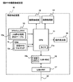
図1は、図2中の画像形成装置10の構成を示す概略のブロック図である。
画像形成装置10は、装置全体をプログラム制御するための制御部としての中央処理装置(Central Processing Unit、以下「CPU」という。)11を有している。CPU11には、時間設定用のタイマ11aが設けられている。このCPU11には、データの消去及び書き換えが可能なメモリ(Random Access Memory、以下「RAM」という。)12と、電力が遮断されても記憶内容が保持される不揮発性メモリとしてのフラッシュメモリ13と、画像処理部14と、画像形成部15と、媒体アクセス制御(Media Access Control、以下「MAC」という。)を行うLAN制御部(以下「LAN−MAC」という。)16と、が接続されている。LAN−MAC16には、ネットワークの物理的な接続・伝送方式を定めた物理層部(以下「LAN−PHY」という。)17が接続され、このLAN−PHY17に、スイッチングハブ21を介してLAN22が接続されている。CPU11には、更に、操作表示部18が接続されている。
FIG. 1 is a schematic block diagram showing the configuration of the
The
CPU11は、フラッシュメモリ13に格納された制御プログラムを実行することによって、画像形成装置10の各機能を実現させる機能を有している。RAM12は、CPU11が制御プログラムを実行するときに必要になる演算領域を提供するメモリであり、これには、受信先入先出フルフラグ(以下「受信FIFOフルフラグ」という。)12aが格納されている。
The
フラッシュメモリ13は、画像形成装置10を制御する所定の設定値が格納されているメモリであり、これには、LAN22の停止時間を決定するためのLAN停止時間決定テーブル13aが格納されている。画像処理部14は、CPU11からの指示に従い、受信データに対して所定の処理を行い、印刷可能な形式の画像データに変換する回路である。画像形成部15は、印刷可能な画像データを用紙等の記録媒体上に形成(印刷)するものであり、モータ等を含む機構部と、電気信号から画像を形成する画像形成プロセス部と、により構成されている。
The
LAN−MAC16は、LAN22とのネットワーク接続の制御の内、MAC層を担う回路であり、受信メモリとしての受信FIFO16aを内蔵している。受信FIFO16aは、LAN22からのネットワークパケットを貯蔵するバッファであり、これに対応する受信FIFOフルフラグ12aが、RAM12内に格納されている。更に、LAN−PHY17は、LAN22とのネットワーク接続の制御の内、PHY(physical layer、物理層)を担う回路である。
The LAN-
図3は、図1の画像形成装置10の機能を示す概略のブロック図である。
画像形成装置10は、印刷機能部としてのネットワーク印刷機能10aと、操作表示機能部としてのパネル操作・表示機能10bと、ネットワーク制御機能部(例えば、ネットワーク輻輳管理機能部としてのLAN輻輳管理機能10c、及び、ネットワーク一時停止機能部としてのLAN一時停止機能10dにより構成されている。)と、を有している。
FIG. 3 is a schematic block diagram showing functions of the
The
ネットワーク印刷機能10aは、CPU11、RAM12、画像処理部14、画像形成部15、及びLAN−MAC16により、LAN22経由による印刷要求を処理する機能である。パネル操作・表示機能10bは、操作表示部18により、ネットワークの設定を行うための操作の要求を受け付け、装置の消耗品の状態等を表示処理する機能である。
The
LAN輻輳管理機能10cは、CPU11、RAM12、フラッシュメモリ13、及びLAN−MAC16により、LAN22が輻輳状態となることにより、CPU11の使用率がネットワークの処理により使い切ってしまう事態を防ぐための機能である。更に、LAN一時停止機能10dは、CPU11、RAM12、フラッシュメモリ13、及びLAN−MAC16により、このLAN−MAC16に対してネットワーク送受信(例えば、ネットワーク受信)の停止及び再開を指示する機能である。
The LAN
図4は、図1中のLAN停止時間決定テーブル13aを示す図である。
このLAN停止時間決定テーブル13aは、LAN22が輻輳状態に到達するまでの時間に応じて、LAN停止時間を決定するテーブルである。
FIG. 4 is a diagram showing the LAN stop time determination table 13a in FIG.
The LAN stop time determination table 13a is a table for determining the LAN stop time according to the time until the
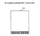
図5は、図1中の受信FIFO16aの貯留データが少ない状態16Aを表した模式図である。
FIG. 5 is a schematic diagram illustrating a
複数のPC20からのブロードキャスト/マルチキャスト等のパケット量が相対的に少ない場合、図5のように、受信FIFO16a内の貯留データは少ない状態16Aとなる。
When the amount of packets such as broadcast / multicast from a plurality of
図6は、図1中の受信FIFO16aの貯留データが格納量の最大値(即ち、100%のフル)に達した状態16Bを表した模式図である。
FIG. 6 is a schematic diagram illustrating a state 16B in which the storage data of the
複数のPC20からのブロードキャスト/マルチキャスト等のパケット量が相対的に多く、画像形成システムの処理性能をネットワークトラフィックが上回る状態が続く場合、図6のように、受信FIFO16a内の貯留データはフルの状態16Bとなる。
When the amount of packets such as broadcast / multicast from a plurality of
図7は、LAN22の負荷が少ない状態11Aにおける、図1中のCPU11の使用率を表した模式図である。
FIG. 7 is a schematic diagram showing the usage rate of the
LAN22の負荷が少ない場合、LANパケットの処理に使われるCPU11のリソース(resource、資源)は少ないため、図7のように、CPU11の使用率は低い状態11Aとなる。
When the load on the
図8は、LAN22の輻輳状態における、図1中のCPU11の使用率を表した模式図である。
FIG. 8 is a schematic diagram showing the usage rate of the
LAN22が輻輳状態の場合、LANパケットの処理でCPUリソースを使い切ってしまうため、図8のように、CPU11の使用率は略100%の状態11Bとなる。この時、パネル操作・表示機能10bであるパネル操作ができない、又は効きにくい等、他の機能(例えば、ネットワーク印刷機能10a)へ影響を及ぼすことになる。
When the
(実施例1の動作)
図1の画像形成装置10内のLAN−PHY17及びLAN−MAC16において、図2中の例えばPC20−1から送信された印刷命令のパケットを受信すると、このパケットが、図5の状態16Aに示すように、受信FIFO16aに貯蔵されていく。CPU11の制御により、受信FIFO16aに貯蔵されたパケットが読み出され、画像処理部14により、印刷可能な形式のビットマップデータ等の画像データに変換される。変換された画像データは、画像形成部15により、用紙等の記録媒体上に印刷される。
(Operation of Example 1)
When the LAN-
次に、図9〜図11を参照しつつ、図1の画像形成装置10の起動後、図2中のLAN22が輻輳となった動作例を説明する。
Next, an operation example in which the
図9は、図2中のLAN22の輻輳状態における図1の画像形成装置10の処理シーケンス(パネル操作可能時)を示す図である。
FIG. 9 is a diagram showing a processing sequence (when panel operation is possible) of the
LAN22が輻輳状態に達すると、ネットワークのパケットを捌ききれなくなる。そのため、図6に示すように、LAN−MAC16内の受信FIFO16aがフルの状態16Bになり、LAN−MAC16からLAN輻輳管理機能10cへ、受信FIFOフル割込みを上げる(ステップS1)。
When the
LAN輻輳管理機能10cは、受信FIFOフル割込みが上がると、RAM12内の受信FIFOフルフラグ12aをチェックする。この時、受信FIFOフルフラグ12aは、クリア状態(消去状態の0)のため、セットする(ステップS2)。
When the reception FIFO full interrupt rises, the LAN
パネル操作・表示機能10bは、定期的(例えば、CPU11内のタイマ11aにより計時された1秒毎)に、RAM12内の受信FIFOフルフラグ12aをクリアする(ステップS3)。パネル操作・表示機能10bが受信FIFOフルフラグ12aをクリアできるということは、LAN22が輻輳状態に達しても、図7の状態11Aに示すように、CPU11がネットワークの処理にリソースを使い切っておらず、パネル操作・表示機能10bが動作可能な状態であることを示している。
The panel operation /
その後、再びLAN22が輻輳状態に達すると、ネットワークのパケットを捌ききれなくなることで、LAN−MAC16内の受信FIFO16aがフルになり、LAN輻輳管理機能10cへ、受信FIFOフル割込みを上げる(ステップS4)。
After that, when the
LAN輻輳管理機能10Cは、受信FIFOフル割込みが上がると、RAM12内の受信FIFOフルフラグ12aをチェックする。この時、受信FIFOフルフラグ12aはクリア状態のため、セットする(ステップS5)。
When the reception FIFO full interrupt rises, the LAN congestion management function 10C checks the reception FIFO
その後、パネル操作・表示機能10bは、定期的な動作により、RAM12内の受信FIFOフルフラグ12aをクリアする(ステップS6)。
Thereafter, the panel operation /
このように、図9の処理シーケンスでは、LAN22が輻輳状態に達しても、CPU11がネットワークの処理にリソースを使い切っていない状態であれば、LAN22の受信を一時停止することをしないようにしている。
As described above, in the processing sequence of FIG. 9, even if the
図10は、図2中のLAN22の輻輳状態における図1の画像形成装置10の処理シーケンス(パネル操作不可能時)を示す図である。
FIG. 10 is a diagram showing a processing sequence (when panel operation is impossible) of the
LAN22が輻輳状態に達すると、ネットワークのパケットを捌ききれなくなる。そのため、LAN−MAC16内の受信FIFO16aがフルになり、LAN−MAC16からLAN輻輳管理機能10cへ受信FIFOフル割込みを上げる(ステップS11)。
When the
LAN輻輳管理機能10cは、受信FIFOフル割込みが上がると、RAM12内の受信FIFOフルフラグ12aをチェックする。この時、受信FIFOフルフラグ12aはクリア状態のため、セットする(ステップS12)。
When the reception FIFO full interrupt rises, the LAN
再び、LAN22が輻輳状態に達すると、ネットワークのパケットを捌ききれなくなる。そのため、LAN−MAC16内の受信FIFO16aがフルになり、LAN−MAC16からLAN輻輳管理機能10cへ受信FIFOフル割込みを上げる(ステップS13)。
Again, when the
LAN輻輳管理機能10cは、受信FIFOフル割込みが上がると、RAM12内の受信FIFOフルフラグ12aをチェックする。この時、受信FIFOフルフラグ12aはクリアされていないことを検出する(ステップS14)。
When the reception FIFO full interrupt rises, the LAN
そのため、LAN輻輳管理機能10cは、ネットワーク処理によるCPUリソースの占有を抑止するため、LAN−MAC16の送受信機能を停止する(ステップS15)。
Therefore, the LAN
次に、LAN輻輳管理機能10cは、パネル操作・表示機能10bに対し、輻輳状態を通知する(ステップS16)。
Next, the LAN
パネル操作・表示機能10bは、パネルに、例えば「ネットワークが輻輳状態です。LANの送受信機能を一時停止します」という旨のメッセージを表示する(ステップS17)。
The panel operation /
LAN輻輳管理機能10cは、CPU11内のタイマ11aで計時された所定のLAN停止時間を待機(ウェイト)後(ステップS18)、LAN−MAC16の送受信機能を再開させ(ステップS19)、RAM12内の受信FIFOフルフラグ12aをクリアする(ステップS20)。
The LAN
その後、LAN輻輳管理機能10cは、パネル操作・表示機能10bに対し、輻輳状態解除を通知する(ステップS21)。
Thereafter, the LAN
それを受けて、パネル操作・表示機能10bは、ステップS17においてパネルに表示したメッセージをクリアする(ステップS22)。
In response, the panel operation /
このように、図10の処理シーケンスでは、LAN22が輻輳状態に達したことに加えて、CPU11がネットワークの処理にリソースを使い切ってパネル操作・表示機能10bが動作不可能な状態であれば、LAN22を介した送受信(例えば、受信)を一時停止することで、CPU11のリソースがネットワーク処理で使い切ってしまわないようにしている。
As described above, in the processing sequence of FIG. 10, in addition to the
図11は、図1の画像形成装置10におけるLAN停止時間決定処理を示すフローチャートである。
FIG. 11 is a flowchart showing a LAN stop time determination process in the
LAN停止時間決定処理が開始され、LAN輻輳管理機能10cは、LAN−MAC16からの受信FIFOフル割込みが発生したか否かを判定する(ステップS31)。その判定結果が、受信FIFOフル割込みでない場合は(NO)、処理を終了する。LAN輻輳管理機能10cは、受信FIFOフル割込みが発生していると判定した場合(YES)、CPU11内のタイマ11aから、LAN輻輳到達時間を取得する(ステップS32)。
The LAN stop time determination process is started, and the LAN
LAN輻輳管理機能10cは、取得したLAN輻輳到達時間を、フラッシュメモリ13内のLAN停止時間決定テーブル13aと照らし合わせ(ステップS33)、図4に示されるように、タイマ11aによって計時されたLAN輻輳到達時間が例えば10秒未満の場合(YES)、LAN停止時間を例えば1分に設定し(ステップS34)、処理を終了する。LAN輻輳管理機能10cは、ステップS33において、図4に示されるように、LAN輻輳到達時間が例えば10秒以上の場合(NO)、LAN停止時間を例えば10秒に設定し(ステップS35)、処理を終了する。
The LAN
このように、LAN輻輳管理機構10cにより、LAN22が輻輳状態に達するまでの時間に応じて、LAN停止時間を変化させることにより、不要なLAN22の停止を防ぐことができる。
As described above, the LAN
(実施例1の効果)
本実施例1によれば、CPU11がネットワークの処理にリソースを使い切ってパネル操作・表示機能10bが動作不可能な状態であれば、LAN22を介した送受信(例えば、受信)を一時停止するようにしている。これにより、CPUリソースがネットワーク処理で使い切ってしまわないようになるので、可用性の向上が期待できる。
(Effect of Example 1)
According to the first embodiment, when the
(変形例)
本発明は、上記実施例1に限定されず、種々の利用形態や変形が可能である。この利用形態や変形例としては、例えば、次の(a)〜(f)のようなものがある。
(Modification)
The present invention is not limited to the first embodiment, and various usage forms and modifications are possible. For example, the following forms (a) to (f) are used as the usage form and the modified examples.
(a) 実施例1においては、受信メモリとしての受信FIFO16aのメモリ容量が100%に達したか否かで受信FIFO16aがフル状態にあるか否かを判断して、フル状態にあれば、RAM12にフルフラグを書き込むことにしている。しかしながら、これに限ったことではなく、最大値としてメモリ容量の80%〜100%の所定値を閾値として設定しておき、その閾値を超えたときにフル状態であると判断して、RAM12にフルフラグを書き込むこととしても良い。
(A) In the first embodiment, it is determined whether or not the
(b) 図1及び図2中のLAN22は、高域ネットワーク(Wide Area Network;WAN)等の他のネットワークであっても、本発明を適用できる。
(B) The present invention can be applied even if the
(c) 図1の画像形成装置10は、他の構成に変更しても良い。これに伴い、図3の各機能を実行するための図1中の構成部分も変更される。
(C) The
(d) 図10の処理シーケンスでは、パネル操作・表示機能10bが動作不可能な場合に、LAN22の送受信を一時停止しているが、パネル操作・表示機能10b以外の他の装置機能が動作不可能な場合にも、本発明を適用できる。
(D) In the processing sequence of FIG. 10, when the panel operation /
(e) 図11中の輻輳到達時間及びLAN停止時間は、一例であり、他の時間に設定しても良い。 (E) The congestion arrival time and LAN stop time in FIG. 11 are examples, and may be set to other times.
(f) 実施例1では、画像形成装置10をプリンタとして説明したが、その画像形成装置10は、プリンタ以外のデジタル複合機(MFP)、複写機、ファクシミリ装置(FAX)等であっても、本発明を適用できる。
(F) In the first embodiment, the
10 画像形成装置
10a ネットワーク印刷機能
10b パネル操作・表示機能
10c LAN輻輳管理機能
10d LAN一時停止機能
11 CPU
12 RAM
12a 受信FIFOフルフラグ
13 フラッシュメモリ
13a LAN停止時間決定テーブル
14 画像処理部
15 画像形成部
16 LAN−MAC
16a 受信FIFO
17 LAN−PHY
18 操作表示部
20,20−1〜20−n PC
22 LAN
DESCRIPTION OF
12 RAM
12a Reception FIFO
16a Receive FIFO
17 LAN-PHY
18
22 LAN
Claims (8)
前記受信メモリに格納された前記受信データに対して所定の処理を行い、印刷可能な形式の画像データに変換し、前記画像データを記録媒体上に形成する印刷機能部と、
前記ネットワークを含む通信の設定、情報の入力操作、及び装置情報の表示を行う操作表示機能部と、
を備え、
前記ネットワーク制御機能部は、
前記受信メモリにおける前記受信データの格納量が最大値に達したことを検出すると、前記ネットワークを介した送受信を一時停止する、
ことを特徴とする画像形成装置。 A network control function unit that has a reception memory, controls communication with the outside via a network, and stores reception data sent from the outside via the network in the reception memory;
A print function unit that performs predetermined processing on the received data stored in the reception memory, converts the received data into image data in a printable format, and forms the image data on a recording medium;
An operation display function unit configured to perform communication setting including the network, input operation of information, and display of device information;
With
The network control function unit
Upon detecting that the amount of received data stored in the reception memory has reached the maximum value, transmission / reception via the network is suspended.
An image forming apparatus.
前記受信メモリにおける前記受信データの前記格納量が最大値に達したことを検出した際に、前記操作表示機能部を含む所定の装置機能部が動作可能な状態と判断した場合には、前記ネットワークを介した送受信を停止しないことを特徴とする請求項1記載の画像形成装置。 The network control function unit
When it is determined that a predetermined device function unit including the operation display function unit is operable when it is detected that the storage amount of the reception data in the reception memory has reached the maximum value, The image forming apparatus according to claim 1, wherein transmission / reception via the network is not stopped.
前記受信メモリにおける前記受信データの前記格納量が最大値に達したことを検出した際に、前記操作表示機能部を含む所定の装置機能部が動作不可能な状態と判断した場合には、前記ネットワークを介した送受信を停止することを特徴とする請求項1又は2記載の画像形成装置。 The network control function unit
When it is determined that the predetermined device function unit including the operation display function unit is inoperable when it is detected that the storage amount of the reception data in the reception memory has reached the maximum value, 3. The image forming apparatus according to claim 1, wherein transmission / reception via a network is stopped.
前記受信メモリにおける前記受信データの前記格納量が最大値に達するまでの時間に応じて、前記ネットワークを介した送受信を一時停止する時間を変更することを特徴とする請求項1〜3のいずれか1項記載の画像形成装置。 The network control function unit
The time for temporarily stopping transmission / reception via the network is changed according to a time until the storage amount of the reception data in the reception memory reaches a maximum value. 2. An image forming apparatus according to item 1.
前記ネットワークが輻輳状態にならないように管理するネットワーク輻輳管理機能部と、
前記ネットワーク輻輳管理機能部の管理結果に基づき、前記ネットワークを介した送受信を一時停止するネットワーク一時停止機能部と、
を有することを特徴とする請求項1〜4のいずれか1項記載の画像形成装置。 The network control function unit
A network congestion management function unit for managing the network so as not to be congested;
Based on the management result of the network congestion management function unit, a network pause function unit for temporarily stopping transmission / reception via the network;
The image forming apparatus according to claim 1, further comprising:
前記受信メモリに格納された前記受信データに対して前記所定の処理を行い、前記印刷可能な形式の画像データに変換する画像処理部と、
前記画像データを前記記録媒体上に形成する画像形成部と、
を有することを特徴とする請求項1〜5のいずれか1項記載の画像形成装置。 The printing function unit
An image processing unit that performs the predetermined processing on the reception data stored in the reception memory and converts the received data into image data in a printable format;
An image forming unit for forming the image data on the recording medium;
The image forming apparatus according to claim 1, wherein the image forming apparatus includes:
前記受信メモリの容量の80%〜100%であることを特徴とする請求項1〜6のいずれか1項記載の画像形成装置。 The maximum value is
The image forming apparatus according to claim 1, wherein the capacity is 80% to 100% of the capacity of the reception memory.
先入先出メモリであることを特徴とする請求項1〜7のいずれか1項記載の画像形成装置。 The reception memory is
The image forming apparatus according to claim 1, wherein the image forming apparatus is a first-in first-out memory.
Priority Applications (1)
| Application Number | Priority Date | Filing Date | Title |
|---|---|---|---|
| JP2015242301A JP2017105118A (en) | 2015-12-11 | 2015-12-11 | Image forming device |
Applications Claiming Priority (1)
| Application Number | Priority Date | Filing Date | Title |
|---|---|---|---|
| JP2015242301A JP2017105118A (en) | 2015-12-11 | 2015-12-11 | Image forming device |
Publications (1)
| Publication Number | Publication Date |
|---|---|
| JP2017105118A true JP2017105118A (en) | 2017-06-15 |
Family
ID=59060394
Family Applications (1)
| Application Number | Title | Priority Date | Filing Date |
|---|---|---|---|
| JP2015242301A Pending JP2017105118A (en) | 2015-12-11 | 2015-12-11 | Image forming device |
Country Status (1)
| Country | Link |
|---|---|
| JP (1) | JP2017105118A (en) |
Citations (8)
| Publication number | Priority date | Publication date | Assignee | Title |
|---|---|---|---|---|
| JPH0531973A (en) * | 1991-07-29 | 1993-02-09 | Canon Inc | Image recording device |
| JPH05303473A (en) * | 1992-04-28 | 1993-11-16 | Nec Home Electron Ltd | Printer device |
| JPH09109482A (en) * | 1995-10-17 | 1997-04-28 | Brother Ind Ltd | Terminal device |
| JPH1195947A (en) * | 1997-09-18 | 1999-04-09 | Canon Inc | Device and method for controlling printing, and storage medium storing computer-readable program |
| JP2005018394A (en) * | 2003-06-26 | 2005-01-20 | Konica Minolta Business Technologies Inc | Print data processor and data processor |
| JP2006048196A (en) * | 2004-08-02 | 2006-02-16 | Toshiba Corp | Network printing system, printer and print data preparation device |
| JP2014210375A (en) * | 2013-04-18 | 2014-11-13 | 株式会社沖データ | Information processing unit |
| US20150067067A1 (en) * | 2013-08-27 | 2015-03-05 | International Business Machines Corporation | Data Communications In A Distributed Computing Environment |
-
2015
- 2015-12-11 JP JP2015242301A patent/JP2017105118A/en active Pending
Patent Citations (8)
| Publication number | Priority date | Publication date | Assignee | Title |
|---|---|---|---|---|
| JPH0531973A (en) * | 1991-07-29 | 1993-02-09 | Canon Inc | Image recording device |
| JPH05303473A (en) * | 1992-04-28 | 1993-11-16 | Nec Home Electron Ltd | Printer device |
| JPH09109482A (en) * | 1995-10-17 | 1997-04-28 | Brother Ind Ltd | Terminal device |
| JPH1195947A (en) * | 1997-09-18 | 1999-04-09 | Canon Inc | Device and method for controlling printing, and storage medium storing computer-readable program |
| JP2005018394A (en) * | 2003-06-26 | 2005-01-20 | Konica Minolta Business Technologies Inc | Print data processor and data processor |
| JP2006048196A (en) * | 2004-08-02 | 2006-02-16 | Toshiba Corp | Network printing system, printer and print data preparation device |
| JP2014210375A (en) * | 2013-04-18 | 2014-11-13 | 株式会社沖データ | Information processing unit |
| US20150067067A1 (en) * | 2013-08-27 | 2015-03-05 | International Business Machines Corporation | Data Communications In A Distributed Computing Environment |
Similar Documents
| Publication | Publication Date | Title |
|---|---|---|
| US8854648B2 (en) | Printing system and printing control apparatus | |
| US9535485B2 (en) | Image processing apparatus, method for controlling the same and storage medium | |
| US20180267755A1 (en) | Print system, server, printer and methods of controlling the same, and storage medium | |
| JP6312076B2 (en) | Image processing apparatus, image processing apparatus control method, and program | |
| JP2007094721A (en) | Printing system | |
| JP5294743B2 (en) | Image forming system, image forming apparatus, image forming apparatus control method, information processing apparatus, information processing apparatus control method and control program, and storage medium | |
| JP2006347110A (en) | Image forming device and alternate printing control program | |
| US8659782B2 (en) | Image forming apparatus using option controller for printing | |
| JP2009070002A (en) | Management system, management method, and management program | |
| JP2014115774A (en) | Printing system, print control device, control method of print control device, and program | |
| JP2002091748A (en) | Image processor | |
| JP2017105118A (en) | Image forming device | |
| JP2011116083A (en) | Printer and control method therefor, program | |
| JP6460905B2 (en) | Communication device, control method, program | |
| JP6172182B2 (en) | Program, information processing apparatus, output management system, and output management method | |
| JP2014135584A (en) | Image forming apparatus | |
| JP5601455B2 (en) | Job processing apparatus and job processing method | |
| US9681007B2 (en) | Processing received image data based on a communication status of an image forming apparatus that receives the image data | |
| JP6497356B2 (en) | Image forming apparatus and image forming apparatus control method | |
| JPH11338652A (en) | Printer controller | |
| EP4187365A1 (en) | Printing apparatus, control method thereof, and program | |
| JP7172333B2 (en) | Image processing system and information processing device | |
| JP4520421B2 (en) | Consumables management device for image forming apparatus | |
| JP4654871B2 (en) | Image forming apparatus | |
| JP2007065797A (en) | Image forming device |
Legal Events
| Date | Code | Title | Description |
|---|---|---|---|
| A621 | Written request for application examination |
Free format text: JAPANESE INTERMEDIATE CODE: A621 Effective date: 20180312 |
|
| A977 | Report on retrieval |
Free format text: JAPANESE INTERMEDIATE CODE: A971007 Effective date: 20181112 |
|
| A131 | Notification of reasons for refusal |
Free format text: JAPANESE INTERMEDIATE CODE: A131 Effective date: 20181120 |
|
| A02 | Decision of refusal |
Free format text: JAPANESE INTERMEDIATE CODE: A02 Effective date: 20190521 |