JP2017104914A - External force follow-up control system - Google Patents
External force follow-up control system Download PDFInfo
- Publication number
- JP2017104914A JP2017104914A JP2015238540A JP2015238540A JP2017104914A JP 2017104914 A JP2017104914 A JP 2017104914A JP 2015238540 A JP2015238540 A JP 2015238540A JP 2015238540 A JP2015238540 A JP 2015238540A JP 2017104914 A JP2017104914 A JP 2017104914A
- Authority
- JP
- Japan
- Prior art keywords
- external force
- control system
- robot arm
- target value
- tracking control
- Prior art date
- Legal status (The legal status is an assumption and is not a legal conclusion. Google has not performed a legal analysis and makes no representation as to the accuracy of the status listed.)
- Pending
Links
Images


Classifications
-
- A—HUMAN NECESSITIES
- A61—MEDICAL OR VETERINARY SCIENCE; HYGIENE
- A61B—DIAGNOSIS; SURGERY; IDENTIFICATION
- A61B34/00—Computer-aided surgery; Manipulators or robots specially adapted for use in surgery
- A61B34/30—Surgical robots
-
- B—PERFORMING OPERATIONS; TRANSPORTING
- B25—HAND TOOLS; PORTABLE POWER-DRIVEN TOOLS; MANIPULATORS
- B25J—MANIPULATORS; CHAMBERS PROVIDED WITH MANIPULATION DEVICES
- B25J13/00—Controls for manipulators
- B25J13/08—Controls for manipulators by means of sensing devices, e.g. viewing or touching devices
Abstract
Description
本発明は、外力追従制御システムに関する。 The present invention relates to an external force tracking control system.
従来、ロボットのアームに対して接触時に回避行動を行えるようにした制御装置が知られている(例えば、特許文献1等参照)。 2. Description of the Related Art Conventionally, there is known a control device that can perform an avoidance action when contacting a robot arm (for example, see Patent Document 1).
このようなものでは、ロボットアームに複数装着されている外力計測用センサの情報に基づいて各関節が制御される。
制御部では、外力計測用センサの情報から各関節に加わるトルクを分離し、設定された関節部仮想インピーダンスからアーム関節部の逃げ量を算出する。
また、設定された手先部仮想インピーダンスからアーム手先の逃げ量を算出する。
そして、制御部では、手先部の逃げ量に、アーム関節部の逃げ量を加算して駆動指令をアームに与える。これにより、アームのどの部位に外力が加わっても適切な回避行動が行われる。
In such a case, each joint is controlled based on information from a plurality of external force measurement sensors attached to the robot arm.
The control unit separates the torque applied to each joint from the information of the external force measurement sensor, and calculates the escape amount of the arm joint from the set joint virtual impedance.
Further, the escape amount of the arm hand is calculated from the set hand tip virtual impedance.
Then, the control unit adds the escape amount of the arm joint portion to the escape amount of the hand portion and gives a drive command to the arm. Thereby, an appropriate avoidance action is performed no matter which part of the arm is applied with an external force.
このようなアーム制御を行なうロボットとして、手術用のロボット、たとえば、内視鏡を操作するスコピストによる補助に代えて、所望の位置に光学視管を保持する内視鏡ホルダロボットなどが知られている。 As a robot for performing such arm control, a surgical robot, for example, an endoscope holder robot that holds an optical tube at a desired position instead of assistance by a scopist who operates an endoscope is known. Yes.
内視鏡ホルダロボットは、手術中にカメラケーブルが引っ張られたり、ホルダに術者が接触したり等、術者の気がつかないうちに、アームに対して外力が加えられていることがある。
このような内視鏡ホルダロボットでは、アームが外力による負荷から開放(除荷)されると、外力が加わる前の姿勢にアームを復帰させようとする。
このため、アームに装着されている光学視管の位置が急激に移動して、内視鏡によって見えていた体内の被観察部位が観察できなくなってしまう。
In the endoscope holder robot, an external force may be applied to the arm before the operator notices, such as a camera cable being pulled during surgery or an operator coming into contact with the holder.
In such an endoscope holder robot, when the arm is released (unloaded) from the load due to the external force, the arm is intended to return to the posture before the external force is applied.
For this reason, the position of the optical viewing tube attached to the arm moves abruptly, making it impossible to observe the site to be observed in the body that was visible by the endoscope.
そこで、本発明は、無負荷時は指令通りに正確に動作し、かつ外力により移動している状態から除荷されても、アームの位置を保持することが出来る外力追従制御システムを提供することを課題としている。 Therefore, the present invention provides an external force follow-up control system that can accurately operate as instructed when there is no load and can maintain the position of the arm even when unloaded from a state of being moved by an external force. Is an issue.
本発明に係る外力追従制御システムは、ロボットアームと、ロボットアームの位置を位置目標値を用いて指示する入力部と、入力部から入力された位置目標値に応じて、ロボットアームを移動させるアクチュエータと、ロボットアームの位置を検出する位置検出部と、位置検出手段で検出されたロボットアームの位置を示す位置応答値と、位置目標値との差分に応じて、アクチュエータを駆動する制御部とを備える。そして、制御部では、ロボットアームに加えられている外力に応じて位置目標値を修正することを特徴としている。 An external force tracking control system according to the present invention includes a robot arm, an input unit that indicates a position of the robot arm using a position target value, and an actuator that moves the robot arm according to the position target value input from the input unit A position detection unit that detects the position of the robot arm, a control unit that drives the actuator in accordance with a difference between the position response value indicating the position of the robot arm detected by the position detection unit, and the position target value. Prepare. The control unit is characterized in that the position target value is corrected according to the external force applied to the robot arm.
このような構成によれば、アクチュエータに出力された位置目標値に応じて、アクチュエータは、ロボットアームを移動させる。
外力が加わると、位置目標値が外力により移動したロボットアームの位置に合わせて修正される。
このため、位置目標値に応じて、移動されたロボットアームは、ロボットアームに加わった外力がなくなっても、外力が加わる以前のもとの位置まで戻ることはない。
According to such a configuration, the actuator moves the robot arm according to the position target value output to the actuator.
When an external force is applied, the position target value is corrected according to the position of the robot arm moved by the external force.
For this reason, the moved robot arm does not return to the original position before the external force is applied even if the external force applied to the robot arm disappears according to the position target value.
本発明によれば、無負荷時は指令通りに正確に動作し、かつ外力により移動している状態から除荷されても、アームの位置を保持することが出来る外力追従制御システムが提供される。 According to the present invention, there is provided an external force follow-up control system that can operate accurately as instructed when there is no load and can maintain the position of the arm even when unloaded from a state of being moved by an external force. .
本発明の実施形態について、図1乃至図6を参照して詳細に説明する。説明において、同一の要素には同一の番号を付し、重複する説明は省略する。 An embodiment of the present invention will be described in detail with reference to FIGS. 1 to 6. In the description, the same elements are denoted by the same reference numerals, and redundant description is omitted.
図1は、実施形態の外力追従制御システムが適用される内視鏡ホルダロボットの斜視図である。
この実施形態の制御対象である内視鏡ホルダロボット10は、主に、ロボット本体11と、ロボット本体11に対して、鉛直方向の軸Yを回転中心として回転可能に設けられた伸縮アーム部30と、この伸縮アーム部30に設けられて、硬性内視鏡20を保持する内視鏡ホルダ部40とを備えている。
FIG. 1 is a perspective view of an endoscope holder robot to which the external force tracking control system of the embodiment is applied.
The
また、手術を行う者の頭部または腕部などには、入力部としてのコントローラ80が装着されている。そして、コントローラ80の動きに合わせて出力された指令信号に応じて、伸縮アーム部30を、軸Yを回転中心として回転移動させたり、あるいは、駆動により、前後方向に、硬性内視鏡20をズーム移動させることが内蔵されたアクチュエータを用いてできるように構成されている。この実施形態では、主に回転系のアクチュエータの制御について記載する。
A
この実施形態の硬性内視鏡20は、先端が体内に挿入され、体内の被観察部の像を導光する光学視管22と、光学視管22を回転自在に接続して、導光された像を受光することにより画像信号を出力するカメラヘッド部24とを含んでいる。
The
カメラヘッド部24には、受光平面を有するCCDイメージセンサが設けられている。CCDイメージセンサは、レンズなどを介して受光平面に結像させた像の光による明暗を電荷の量に光電変換し、それを順次読み出して電気的な画像信号に変換する。
そして、カメラヘッド部24のCCDイメージセンサから出力された画像信号は、画像生成装置により出力画像信号として生成されて、出力されることにより図示しないモニタに体内の被観察部位を映し出すように構成されている。
The
Then, the image signal output from the CCD image sensor of the
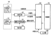
図2は、実施形態の外力追従制御システムで、各部の構成を説明する構成図である。
内視鏡ホルダロボット10は、入出力部60を介して、制御部70に接続されている。
この実施形態の内視鏡ホルダロボット10は、ロボット本体11の鉛直方向の軸Y(図1参照)を回転中心として伸縮アーム部30を回転駆動するアクチュエータとしての空気圧アクチュエータ12と、この空気圧アクチュエータ12によって回転した伸縮アーム部30の回転角度を検出する位置検出手段としての光学式ロータリーエンコーダ14を含む。
FIG. 2 is a configuration diagram illustrating the configuration of each unit in the external force tracking control system of the embodiment.
The
The
このうち、空気圧アクチュエータ12は、空気圧送ポンプなどの動力源16から圧送される空気を駆動力としている。そして、この空気圧アクチュエータ12は、駆動力制御装置18に接続されている。この駆動力制御装置18は、入出力部60からの駆動力制御信号に応じて、空気圧アクチュエータ12を駆動する。
Among these, the
光学式ロータリーエンコーダ14は、軸Y(図1参照)を回転中心とする伸縮アーム部30の回転位置を検出する。そして、回転位置を電気的信号に変換して位置応答値として、入出力部60に出力するように構成されている。
The optical
また、この実施形態の内視鏡ホルダロボット10には、力検出部42が設けられている。そして、力検出部42は、力応答値としての力信号および外力信号を入出力部60に出力するように構成されている。
In addition, the
このように構成された実施形態の内視鏡ホルダロボット10は、制御部70からの制御指令を、入出力部60によって駆動力信号に変換する際、入出力部60に入力する位置信号、力信号、および外力信号などの状態量に応じて、フィードバックすることにより所望の位置および回転角度に伸縮アーム部30を移動させるように構成されている。
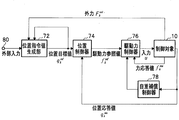
図3は、実施形態の外力追従制御システムで、機能ブロック図である。この実施形態の内視鏡ホルダロボット10の位置制御系は、主に、制御部70内に設けられていて、位置指令値生成部72、位置制御器74、駆動力制御器76、自重補償制御器78を含んでいる。
The
FIG. 3 is a functional block diagram of the external force tracking control system according to the embodiment. The position control system of the
このうち、位置指令値生成部72は、コントローラ80と接続されていて、コントローラ80のボタン操作などによる外部入力が位置指令値生成部72に入力されるように構成されている。
この位置指令値生成部72には、さらに、制御対象である内視鏡ホルダロボット10の伸縮アーム部30の状態(回転角度)および推定もしくは計測した外力の値を状態量として位置目標値を生成し、この位置目標値を出力する。
また、前記光学式ロータリーエンコーダ14で検出された実際の伸縮アーム部30の回転位置を示す位置応答値は、入出力部60を介して制御部70に入力されている。位置応答値は、位置応答値としては、このような位置検出部からの位置信号に限らず、この位置信号が生成した信号(速度推定値など)を位置応答値として用いてもよい。
Among these, the position command
The position command
The position response value indicating the actual rotational position of the
位置制御器74には、位置目標値と制御対象からの位置応答値との差分が入力される。
位置制御器74は、位置目標値と制御対象からの位置応答値との差分を0にするような位置制御のために演算を実行し、その演算結果として駆動力参照値を生成している。駆動力参照値は、位置制御器74から出力されることによりアクチュエータを駆動してロボットアームの位置を指令する。
The
The
駆動力制御器76には、駆動力参照値と制御対象からの力応答値との差分が入力される。
駆動力制御器76は、駆動力参照値と制御対象からの力応答値(=力信号)との差分を0にするような駆動力信号を、制御対象である内視鏡ホルダロボット10に入力として与えて駆動力制御を実行している。この実施形態の入力は、駆動力制御装置18として実装されているサーボ弁118等への印加電圧(V)である。
A difference between the driving force reference value and the force response value from the control target is input to the driving
The driving
なお、この実施形態では、制御特性の改善を図るため、自重補償制御器78などを用いて、位置応答値(=位置信号)に基づいた自重補償力などのフィードフォワード補償を行なってもよい。
自重補償制御器78は、予め想定される内視鏡ホルダロボット10の自重の影響を取り除くためのものである。
すなわち、伸縮アーム部30は、内視鏡の光学視管22を装着した状態で、動作位置(回転角度)によって、自重による影響を相違させる。このため、自重補償制御器78を用いて、このような内視鏡ホルダロボット10の自重の影響をキャンセルさせる自重補償力をフィードフォワード補償として行なうことにより、さらに制御特性を向上させることができる。
In this embodiment, in order to improve the control characteristics, feedforward compensation such as self weight compensation force based on the position response value (= position signal) may be performed using the self
The dead
In other words, the
力応答値としては、力検出部42からの力信号と、加えられている外力を推定値として出力する外力信号との2種類が考えられる。力信号または外力信号は、入出力部60を介して制御部70に入力される。
力検出部42は、たとえば推定値を算出するアルゴリズムであってもよい。また、内視鏡ホルダロボット10内に設けられた力センサなどの手段を用いて力信号を得るように構成してもよい。
There are two types of force response values: a force signal from the
The
駆動力参照値と力応答値との差分は、駆動力制御器76に入力される。駆動力制御器76は、駆動力参照値と力応答値との差分を0とするように制御を行なう。そして制御結果として駆動力信号を出力する(図2参照)。駆動力信号は、駆動力制御装置18に入力されて、空気圧アクチュエータ12を駆動して伸縮アーム部30を移動させる。
The difference between the driving force reference value and the force response value is input to the driving
位置応答値は、光学式ロータリーエンコーダ14で計測した現在位置を示す状態量である。駆動力は圧力センサ等の力検出部42にて検出された値にサーボ弁のシリンダの受圧面積を乗算して求められる。そして、各センサで検出された状態量は、力信号または外力信号として入出力部60に内視鏡ホルダロボット10から入力される。
The position response value is a state quantity indicating the current position measured by the optical
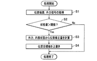
図4は、実施形態の外力追従制御システムの動作を説明するフローチャートである。
この実施形態では、位置指令値生成部72において、外力により生じた伸縮アーム部30の位置偏差、あるいは外力信号が取得される。
そして、制御対象に事前に設定した値を超える力が負荷として加えられた場合、コントローラ80による位置目標値を力が逃げる(除荷される)方向に修正するように構成されている。
FIG. 4 is a flowchart for explaining the operation of the external force tracking control system of the embodiment.
In this embodiment, the position command
When a force exceeding a preset value is applied as a load to the control target, the position target value by the
一方、一般的なコンプライアンス制御・インピーダンス制御では、位置目標値を外力によって修正する。このため、負荷が開放(除荷)されたあとは、修正前の位置目標値に戻る動作が発生する。
これに対して本実施形態の外力追従制御システムでは、位置目標値を外力に応じて更新しながら上書きする。このため、負荷の開放による伸縮アーム部30の戻り動作が発生しない。
すなわち、図4にて、処理が開始されると、ステップS1では、位置偏差、外力信号が取得される。
On the other hand, in general compliance control / impedance control, the position target value is corrected by an external force. For this reason, after the load is released (unloaded), an operation of returning to the position target value before correction occurs.
In contrast, in the external force tracking control system of the present embodiment, the position target value is overwritten while being updated according to the external force. For this reason, the return operation | movement of the expansion-
That is, when the process is started in FIG. 4, in step S1, a position deviation and an external force signal are acquired.
ステップS2では、状態量が閾値を上回っているか否かが判定される。状態量が閾値を上回っている場合(ステップS2にてYES)には、次のステップS3に処理が進み、状態量が閾値を上回っていない場合(ステップS2にてNO)には、処理を終了する。
ここで、偏差が予め設定された閾値eLimitを超えていた場合、ステップS2において下記の数1の式(1)にて、位置目標値qref(例えば30度)を修正する。

ステップS3では、外力、内部状態から位置修正量を計算する。この位置修正には、修正アルゴリズムが操作する時間Tの設定が含まれる。
そして、修正処理が開始されてからの時間がカウントされて、アルゴリズムの動作時間内である場合は、ステップS3において、下記の数2の差分方程式(式2)にて位置目標値を修正する。
ここで、Tは収束させるための時間、stは制御周期、Qは修正速度を調整するパラメータである。
ステップS4では、位置目標値を更新しながら上書きして処理を終了する。
In step S2, it is determined whether or not the state quantity exceeds a threshold value. If the state quantity exceeds the threshold value (YES in step S2), the process proceeds to the next step S3. If the state quantity does not exceed the threshold value (NO in step S2), the process ends. To do.
Here, when the deviation exceeds a preset threshold eLimit, the position target value q ref (for example, 30 degrees) is corrected by the following equation (1) in Step S2.
In step S3, the position correction amount is calculated from the external force and the internal state. This position correction includes setting the time T during which the correction algorithm operates.
Then, when the time since the start of the correction process is counted and within the operation time of the algorithm, the position target value is corrected by the difference equation (Equation 2) of the following
Here, T is a time for convergence, st is a control period, and Q is a parameter for adjusting the correction speed.
In step S4, the position target value is overwritten while being updated, and the process is terminated.
この実施形態の外力追従制御システムでは、位置目標値の修正に係る時間の上限と速さを制御周期stおよび修正速度Qの設定により指定することができる。
また、この実施形態の外力追従制御システムでは、光学式ロータリーエンコーダ14によって検出された状態量として位置偏差のみを用いることで、外力信号および外力の検出手段もしくは外力の推定機構を別途設ける必要がない。
In the external force tracking control system of this embodiment, the upper limit and speed of time required for correcting the position target value can be specified by setting the control cycle st and the correction speed Q.
Further, in the external force tracking control system of this embodiment, by using only the position deviation as the state quantity detected by the optical
また、現在状態量であるqを位置目標値qrefと比較して(ステップS2)、ステップS3にて位置修正量を計算している。このため、外力を受け流して目標位置をステップS4にて上書き更新することにより、外力がなくなったときに実測値を目標値に収束させることができる。
したがって、たとえば空気圧アクチュエータなどバックドライバビリティが存在する医療用ロボットなどに用いて好適である。
Further, the current state quantity q is compared with the position target value q ref (step S2), and the position correction amount is calculated in step S3. For this reason, the measured value can be converged to the target value when the external force disappears by receiving the external force and overwriting and updating the target position in step S4.
Therefore, it is suitable for use in medical robots having back drivability such as pneumatic actuators.
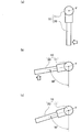
図5は、実施形態の外力追従制御システムで、検証結果を示すグラフ図である。また、図6は、実施形態の外力追従制御システムで、(a)は、アームに外力が加わった状態を示す模式的な平面図である。(b)は、実施形態の外力追従制御システムで、アームに外力が加わり続けている様子を示す模式的な平面図である。(c)は、実施形態の外力追従制御システムで、アームに外力が加わらなくなった状態を示す模式的な平面図である。 FIG. 5 is a graph showing a verification result in the external force tracking control system of the embodiment. FIG. 6 is an external force tracking control system according to the embodiment, and FIG. 6A is a schematic plan view showing a state in which an external force is applied to the arm. (B) is a schematic plan view showing a state in which an external force continues to be applied to an arm in the external force tracking control system of the embodiment. (C) is a schematic plan view showing a state in which no external force is applied to the arm in the external force tracking control system of the embodiment.
ここでは、状態量として内視鏡ホルダロボット10の伸縮アーム部30の角度を、外力が加わっていない状態を0度、閾値を30度として説明する。
図5中、測定開始から4秒が経過した時点aにて、図6中矢印で示すように周方向に伸縮アーム部30を回転させる外力が加わると、伸縮アーム部30の回転角度が増大する。そして、位置指令値と位置応答値との間の乖離が30度をこえた時点bから位置指令値の追従が開始される。
Here, the angle of the
In FIG. 5, when an external force is applied to rotate the
時点cにて、伸縮アーム部30の位置が図6(b)に示すように約80度に到達する。時点cから時点dまでは、伸縮アーム部30に対して、継続して外力が加わっている状態であり、伸縮アーム部30の位置は、約80度にて保持される。
At the time point c, the position of the
時点dにて、修正アルゴリズムが開始された時点bから予め設定された一定の時間Tを経過すると修正アルゴリズムが終了する。
そして、時点eにて、伸縮アーム部30に加わっていた外力が除荷される。
時点eから、時点fまでの時間にて伸縮アーム部30は、位置制御の働きによって、位置指令値によって指定された角度(ここでは約72度)に戻る(図6(c)参照)。
At a time point d, the correction algorithm ends when a predetermined time T elapses from a time point b at which the correction algorithm is started.
At time e, the external force applied to the
The
しかしながら、戻り角度は伸縮アーム部30がもとの図6(a)に示す位置に急激に戻るような動作と比較して大きくなく、回動速度も速くならないように抑制されている。
このため、急激に元の外力が加わる前の姿勢となることなく、この例では、約80度の位置に伸縮アーム部30は停止し続ける。したがって、伸縮アーム部30に装着されている光学視管22の位置が移動しないため、継続して体内の被観察部位を安全に観察できる。
However, the return angle is not large as compared with the operation in which the
For this reason, in this example, the
そして、時点f以降は、位置指令値と位置応答値とが一致し続ける。このように、この実施形態の内視鏡ホルダロボットでは、外力を受け流して、目標位置を現在位置にて上書きして更新することにより、外力がなくなったときに実測値を目標値に収束させることができる。 After time point f, the position command value and the position response value continue to match. Thus, in the endoscope holder robot of this embodiment, the measured value is converged to the target value when the external force disappears by receiving the external force and overwriting and updating the target position at the current position. Can do.
また、術者の手による硬性内視鏡20の位置決めを行なうことにより、初期に与えられる位置目標値が実測値により上書きされる。このため、続いて行なわれる伸縮アーム部30の自立制御への移行を、切り替えスイッチなどの操作を用いずにシームレスに行なえる。よって、円滑な手術の進行を妨げることがない。
(位置を基準とする方式)
Further, by positioning the
(Method based on position)
図7は、実施例1の外力追従制御システムで、各部の構成を説明する構成図である。
なお、前記実施形態の図2と同一部分には、同一符号を付して説明を省略する。
まず構成から説明すると、この実施例1の外力追従制御システムでは、内視鏡ホルダロボット110の駆動力制御装置としてサーボ弁118が設けられている。
FIG. 7 is a configuration diagram illustrating the configuration of each unit in the external force tracking control system according to the first embodiment.
Note that the same parts as those in FIG.
First, the configuration will be described. In the external force tracking control system of the first embodiment, a
サーボ弁118は、動力源としての圧縮空気源116から空気圧アクチュエータ12の制御に用いる圧縮空気の供給を受けるように構成されている。このサーボ弁118は、入出力部60からの駆動力信号を受けて圧縮空気を調整する。力検出部としての圧力センサ120は、サーボ弁118の圧力を検出して、力信号として入出力部60に出力する。
そして、制御部70では、この力信号を力応答値として用いて駆動力信号を生成することにより、内視鏡ホルダロボット110の伸縮アーム部30を空気圧アクチュエータ12によって駆動するように構成されている。
The
The
図8は、実施例1の外力追従制御システムで、機能ブロック図である。
この実施例1の内視鏡ホルダロボット110の位置制御系は、主に、制御部70内に設けられていて、位置指令値生成部72、位置制御器74、駆動力制御器76、自重補償制御器78を含んでいる。
そして、状態量として伸縮アーム部30の回転位置を用いて偏差から、外力を推定して、位置目標値を修正するように、駆動力制御器76は、入力uを制御対象である内視鏡ホルダロボット10に与えるように構成されている。
FIG. 8 is a functional block diagram of the external force tracking control system according to the first embodiment.
The position control system of the
Then, the driving
図9は、実施例1の外力追従制御システムの動作を説明するフローチャートである。
すなわち、図9にて、処理が開始されると、ステップS11では、位置偏差が取得される。
FIG. 9 is a flowchart for explaining the operation of the external force tracking control system according to the first embodiment.
That is, when the process is started in FIG. 9, the position deviation is acquired in step S11.
ステップS12では、位置偏差が閾値を上回っているか否かが判定される。位置偏差が閾値を上回っている場合(ステップS12にてYES)には、次のステップS13に処理を進めて、位置目標値を修正するとともに、修正アルゴリズムが操作する時間Tの設定である修正時間をリセットする。
また、位置偏差が閾値を上回っていない場合(ステップS12にてNO)には、処理をステップS14に進める。
In step S12, it is determined whether or not the position deviation exceeds a threshold value. If the position deviation exceeds the threshold value (YES in step S12), the process proceeds to the next step S13 to correct the position target value, and the correction time that is the time T set by the correction algorithm. To reset.
If the position deviation does not exceed the threshold value (NO in step S12), the process proceeds to step S14.
ステップS14では、修正時間内であるか否かが判定される。修正時間内である場合(ステップS14にてYES)、ステップS15に処理を進め、修正時間内でない場合(ステップS14にてNO)、処理を終了する。 In step S14, it is determined whether it is within the correction time. If it is within the correction time (YES in step S14), the process proceeds to step S15. If it is not within the correction time (NO in step S14), the process ends.
ステップS15では、位置修正量の計算が行われる。そして、ステップS16にて修正時間のカウントアップが行われて、ステップS17にて位置目標値を出力するとともに、処理を終了する。
これにより、実施例1の外力追従制御システムでは、無負荷時は指令通りに正確に動作し、かつ外力により移動している状態から除荷されても、アームの位置を保持することが出来る。
In step S15, a position correction amount is calculated. In step S16, the correction time is counted up. In step S17, the position target value is output, and the process is terminated.
Thus, in the external force tracking control system according to the first embodiment, the arm position can be maintained even when the load is removed from the state of being moved by the external force when it is not loaded and operates accurately as instructed.
このように、実施例1では、実施形態の外力追従制御システムの作用効果に加えてさらに、フィードバック制御に用いる光学式ロータリーエンコーダ14のような既設の位置センサを用いて、簡便に、異常外力に対する追従および戻り動作の抑制制御を行なうことができる。
As described above, in Example 1, in addition to the operation and effect of the external force tracking control system of the embodiment, an existing position sensor such as the optical
(力を基準とする方式)
図10は、実施例2の外力追従制御システムで、各部の構成を説明する構成図である。
なお、前記実施形態および実施例1と同一部分には、同一符号を付して説明を省略し、各部の構成について相違点を中心に説明する。
(Method based on force)
FIG. 10 is a configuration diagram illustrating the configuration of each unit in the external force tracking control system according to the second embodiment.
The same parts as those in the embodiment and the first embodiment are denoted by the same reference numerals and description thereof is omitted, and the configuration of each part will be described focusing on the differences.
この実施例2の外力追従制御システムでは、位置修正を行なうか否かの判定基準とする状態量として外力を用いている。そして、外力を検出する力検出部122として、空気圧アクチュエータ12の制御用の圧力センサ120とは、別体で伸縮アーム部30に加わる外力を検出する力センサ124を設けている。
In the external force tracking control system of the second embodiment, an external force is used as a state quantity as a criterion for determining whether or not position correction is performed. As a
そして、図示しない動力源としての圧縮空気源から空気圧アクチュエータの制御に用いる圧縮空気の供給を受けたサーボ弁118は、力検出部としての圧力センサ120によって圧力が検出されて、力信号として入出力部60に出力する。
The
実施例2では、この力信号とは独立して、力検出部122には、外力信号を出力する力センサ124が設けられている。
この力センサ124は、内視鏡ホルダロボット210の可動部分である伸縮アーム部30などに設けられて、伸縮アーム部30に加えられる外力を検出可能としている。力センサ124によって検出された外力は外力信号として入出力部60に送られるように構成されている。
In the second embodiment, a
The
図11は、実施例2の外力追従制御システムで、機能ブロック図である。
このように構成された実施例2の外力追従制御システムでは、圧力センサ120で検出された外力Fextが、閾値Fext Limitを超えた場合、図4のステップS3にて、以下の数3の式(3)を用いて位置目標値qrefが修正される。
ここで、Kは外力と位置修正値とを関係づける仮想コンプライアンスである。Kは、たとえばバネのような概念である。また、Tは収束させるための時間、stは制御周期、Qは修正速度を調整するパラメータである。なお、後述するばねの概念に加えてダンパ成分や質量も加えた概念(仮想インピーダンス)を用いてもよい。
FIG. 11 is a functional block diagram of the external force tracking control system according to the second embodiment.
In the external force tracking control system of the second embodiment configured as described above, when the external force F ext detected by the
Here, K is a virtual compliance that relates the external force and the position correction value. K is a concept like a spring, for example. T is a time for convergence, st is a control period, and Q is a parameter for adjusting the correction speed. A concept (virtual impedance) in which a damper component and mass are added in addition to the concept of a spring described later may be used.
次にこの実施例2の外力追従制御システムの作用効果について説明する。実施例2の外力追従制御システムでは、空気圧アクチュエータ12を駆動する際に用いる圧力センサ120とは、独立して、力検出部122に力センサ124が設けられている。
Next, the effect of the external force tracking control system of the second embodiment will be described. In the external force tracking control system of the second embodiment, the
このため、独立して、伸縮アーム部30に加えられる外力を検出可能である。このため、状態量として外力を用いることにより、位置制御に用いるサーボの機械的な剛性と外力への応答とを独立させて設計することが可能である。したがって例えば、減速機を用いた電動モータなどの構成を有する外力追従制御システムに用いて好適である。
他の構成および作用効果については、前記実施形態および実施例1と同様であるので説明を省略する。
(外力を推定する方式)
For this reason, the external force applied to the
Other configurations and functions and effects are the same as those of the above-described embodiment and Example 1, and thus description thereof is omitted.
(Method to estimate external force)
図12は、実施例3の外力追従制御システムで、各部の構成を説明する構成図である。
なお、前記実施形態および実施例1,2と同一部分には、同一符号を付して説明を省略する。
まず構成上の相違点から説明すると、実施例3の外力追従制御システムに用いられる制御部170には、外力推定器171が設けられている。
外力推定器171は、伸縮アーム部30に加わる外力を、空気圧アクチュエータ12の駆動状況から推定して算出することができる。
FIG. 12 is a configuration diagram illustrating the configuration of each unit in the external force tracking control system according to the third embodiment.
In addition, the same code | symbol is attached | subjected to the part same as the said embodiment and Example 1, 2, and description is abbreviate | omitted.
First, in terms of structural differences, the
The
図13は、実施例3の外力追従制御システムで、機能ブロック図である。この実施例3の外力追従制御システムでは、外力推定器171に、駆動力参照値fk refと、位置応答値qresとが入力される。
そして、伸縮アーム部30に加えられた力から、伸縮アーム部30の駆動のために内視鏡ホルダロボット10が使用した力を引くことにより、伸縮アーム部30にかかっている外力が推定されるように構成されている。
FIG. 13 is a functional block diagram of the external force tracking control system according to the third embodiment. In the external force tracking control system according to the third embodiment, the driving force reference value f k ref and the position response value q res are input to the
The external force applied to the
推定された外力は、位置指令値生成部72に推定外力として入力されて、前記実施例1,2と同様に、位置指令値生成部72にて位置目標値の生成に用いられる。なお、光学式ロータリーエンコーダ14で計測した伸縮アーム部30の角度が位置目標値と一定の閾値以上の偏差を発生させた場合に、外力の推定を開始するようにしてもよい。
The estimated external force is input as an estimated external force to the position command
この実施例3の外力追従制御システムでは、前記実施例2の外力追従制御システムと比較して、力検出部122としての力センサ124が不要となる。このため、別途、力センサ124を装着する際のコスト等を削減することができる。他の構成および作用効果については、前記実施例2の外力追従制御システムの作用効果と同様であるので説明を省略する。
In the external force follow-up control system according to the third embodiment, the
図14は、実施例3の変形例1の外力追従制御システムで、外力を推定する機能ブロック図である。この変形例1の外力推定器271は、伸縮アーム部30の質量をMn、駆動力参照値を力応答値とみなせる場合、次の数4の式(4)にて、推定外力の推定が行なわれる。
![]()
他の構成および作用効果については、前記実施例3の外力追従制御システムの作用効果と同様であるので説明を省略する。
FIG. 14 is a functional block diagram for estimating an external force in the external force tracking control system according to the first modification of the third embodiment. In the
![]()
Other configurations and operational effects are the same as the operational effects of the external force tracking control system according to the third embodiment, and thus the description thereof is omitted.
図15は、実施例3の変形例2の外力追従制御システムで、外力を推定する機能ブロック図である。ここで、sはラプラス演算子で、s2は、二階微分を示している。この変形例2の外力推定器371は、伸縮アーム部30の質量をMn、伸縮アーム部30の関節の粘性摩擦力をBnとした場合、次の数5の式(5)にて、推定外力の推定が行なわれる。
![]()
![]()
このように、内視鏡ホルダロボット10の伸縮アーム部30の駆動のために使用した力を求める際、必要に応じて、重力やあるいは静止摩擦などの内部動力学補償項を加えることにより、さらに、外力を推定する際の精度を向上させることができる。他の構成および作用効果については、前記実施例3の外力追従制御システムの作用効果と同様であるので説明を省略する。
In this way, when obtaining the force used for driving the
上述してきたように、この実施形態の外力追従制御システムが適用される内視鏡ホルダロボット10は、腹腔鏡手術において使用される内視鏡を固定もしくは操作者による外部入力によって内視鏡を正確に移動させることができる。
As described above, the
また、手術中の術者との接触などにより外力が加わっても、実施形態の外力追従制御システムでは、外力が除荷された際に、伸縮アーム部30が急激な移動を起こすことがない。したがって、従来の内視鏡ホルダロボット10に増してさらに、カメラケーブルが引っ張られたり、ホルダに接触したり等、アームに対して外力が加わった場合でも、外力が加わる以前のもとの位置まで戻ることはない。
Further, even when an external force is applied due to contact with the surgeon during the operation, in the external force tracking control system according to the embodiment, the
このため、この外力追従制御システムでは、無負荷時は指令通りに正確に動作し、かつ外力により移動している状態から除荷されても、硬性内視鏡20を保持する伸縮アーム部30の位置を保持することが出来る。
よって、伸縮アーム部30に装着されている光学視管22の位置が移動しないため、継続して体内の被観察部位を安全に観察できる。
For this reason, in this external force tracking control system, when there is no load, the
Therefore, since the position of the optical
以上、本実施形態に係る外力追従制御システムについて詳述してきたが、本発明はこれらの実施形態に限定されるものではなく、本発明の趣旨を逸脱しない範囲で適宜変更可能であることは言うまでもない。 The external force tracking control system according to the present embodiment has been described in detail above. However, the present invention is not limited to these embodiments, and it is needless to say that the external force tracking control system can be appropriately changed without departing from the gist of the present invention. Yes.
例えば、本実施形態では、空気圧アクチュエータ12によって回転した伸縮アーム部30の回転角度を検出する位置検出手段として、光学式ロータリーエンコーダ14を用いたものを示して説明してきたが、他の位置エンコーダやポテンショメータを用いて、ロボットアームの位置を検出するようにしてもよい。
また、入力部として、コントローラ80を示して説明してきたがジャイロセンサやパネル入力など、他の入力装置を用いて、入力部が構成されていてもよい。
For example, in the present embodiment, the position detection unit that uses the optical
Further, although the
そして、アクチュエータとして空気圧アクチュエータ12を用いたものを示して説明してきたが特にこれに限らず、たとえば、電動モータ(AC,DC,ステッピングモータなど)、油圧モータ、空気圧モータのようなアクチュエータであってもよく、アクチュエータの形状、数量および種類が特に限定されるものではない。
In addition, the actuator using the
また、実施形態では、空気圧送ポンプなどの動力源16を用いているが特にこれに限らず、電源を動力源として用いてもよく、動力制御装置としてサーボ弁の他、他の形式のバルブやモータドライバを用いてもよい。
さらに、力検出部としての圧力センサ120などを用いるものを示して説明してきたが、特にこれに限らず、たとえば、力センサ、電流検出回路などでもよく、その他、力を推定する力推定手段などを用いてもよい。
さらに、実施例3にて設明したように外力と位置修正値とを関係づけるために例えば、仮想の粘性、質量を考慮した仮想インピーダンスなどを用いるとなおよい。
In the embodiment, the
Furthermore, the description has been made by using the
Further, as described in the third embodiment, in order to relate the external force and the position correction value, for example, it is more preferable to use virtual impedance considering virtual viscosity and mass.
そして、この実施形態では、外力追従制御システムを内視鏡ホルダロボット10に用いたものを示して説明してきたが特にこれに限らず、他の医療用ロボットや、産業用ロボットなど、外部環境との物理的な接触が想定される機械構造物全般の制御に用いるように構成してもよい。
In this embodiment, the external force tracking control system is shown and described for the
10 内視鏡ホルダロボット
11 ロボット本体
12 空気圧アクチュエータ
14 光学式ロータリーエンコーダ
16 動力源
18 動力制御装置
20 硬性内視鏡
22 光学視管
24 カメラヘッド部
30 伸縮アーム部
40 内視鏡ホルダ部
42 力検出部
60 入出力部
70 制御部
72 位置指令値生成部
74 位置制御器
76 駆動力制御器
78 自重補償制御器
80 コントローラ(入力部)
110 内視鏡ホルダロボット
116 圧縮空気源
118 サーボ弁
120 圧力センサ
122 力検出部
124 力センサ
170 制御部
171,271,371 外力推定器
210 内視鏡ホルダロボット
DESCRIPTION OF
DESCRIPTION OF
Claims (11)
前記ロボットアームの位置を位置目標値を用いて指示する入力部と、
前記入力部から入力された位置目標値に応じて、前記ロボットアームを移動させるアクチュエータと、
前記ロボットアームの位置を検出する位置検出部と、
前記位置検出手段で検出されたロボットアームの位置を示す位置応答値と、前記位置目標値との差分に応じて、前記アクチュエータを駆動する制御部と、を備え、
前記制御部は、前記ロボットアームの状態量に応じて前記位置目標値を修正することを特徴とする、外力追従制御システム。 A robot arm,
An input unit for instructing the position of the robot arm using a position target value;
An actuator for moving the robot arm according to a position target value input from the input unit;
A position detector for detecting the position of the robot arm;
A controller that drives the actuator in accordance with a difference between a position response value indicating the position of the robot arm detected by the position detecting means and the position target value;
The external force follow-up control system, wherein the control unit corrects the position target value in accordance with a state quantity of the robot arm.
外力追従制御システム。 The external force tracking control system according to claim 1, wherein the control unit corrects the position target value according to an external force applied to the robot arm.
External force tracking control system.
Priority Applications (2)
| Application Number | Priority Date | Filing Date | Title |
|---|---|---|---|
| JP2015238540A JP2017104914A (en) | 2015-12-07 | 2015-12-07 | External force follow-up control system |
| PCT/JP2016/085752 WO2017098989A1 (en) | 2015-12-07 | 2016-12-01 | External force tracking control system |
Applications Claiming Priority (1)
| Application Number | Priority Date | Filing Date | Title |
|---|---|---|---|
| JP2015238540A JP2017104914A (en) | 2015-12-07 | 2015-12-07 | External force follow-up control system |
Publications (2)
| Publication Number | Publication Date |
|---|---|
| JP2017104914A true JP2017104914A (en) | 2017-06-15 |
| JP2017104914A5 JP2017104914A5 (en) | 2018-03-08 |
Family
ID=59014113
Family Applications (1)
| Application Number | Title | Priority Date | Filing Date |
|---|---|---|---|
| JP2015238540A Pending JP2017104914A (en) | 2015-12-07 | 2015-12-07 | External force follow-up control system |
Country Status (2)
| Country | Link |
|---|---|
| JP (1) | JP2017104914A (en) |
| WO (1) | WO2017098989A1 (en) |
Cited By (2)
| Publication number | Priority date | Publication date | Assignee | Title |
|---|---|---|---|---|
| WO2020050314A1 (en) * | 2018-09-06 | 2020-03-12 | リバーフィールド株式会社 | Arm device, control method, and program |
| WO2021161718A1 (en) * | 2020-02-12 | 2021-08-19 | リバーフィールド株式会社 | Surgical robot and surgical robot control unit |
Families Citing this family (2)
| Publication number | Priority date | Publication date | Assignee | Title |
|---|---|---|---|---|
| JP2021003201A (en) * | 2019-06-25 | 2021-01-14 | ソニー株式会社 | Surgical microscope system, control device and control method |
| GB2596543A (en) * | 2020-06-30 | 2022-01-05 | Cmr Surgical Ltd | Controlling a surgical instrument |
Citations (9)
| Publication number | Priority date | Publication date | Assignee | Title |
|---|---|---|---|---|
| JPH0639760A (en) * | 1992-07-23 | 1994-02-15 | Hitachi Ltd | Control device for robot |
| JP2000279463A (en) * | 1999-03-31 | 2000-10-10 | Sanyo Electric Co Ltd | Training device for superior limb function recovery |
| JP2006230691A (en) * | 2005-02-24 | 2006-09-07 | Shin Meiwa Ind Co Ltd | Medical device support arm |
| JP2009018380A (en) * | 2007-07-12 | 2009-01-29 | Toyota Motor Corp | Robot, control method of the robot, and control system of the robot |
| JP2009527366A (en) * | 2006-02-24 | 2009-07-30 | フェルロボティクス コンプライアント ロボット テクノロジー ゲーエムベーハー | Robot arm |
| JP2010247309A (en) * | 2009-04-20 | 2010-11-04 | Toyota Motor Corp | Robot arm and method for controlling the same |
| JP2012130977A (en) * | 2010-12-20 | 2012-07-12 | Toshiba Corp | Robot control apparatus |
| JP2015100677A (en) * | 2013-11-28 | 2015-06-04 | 国立大学法人東京工業大学 | Surgical robot |
| WO2015137140A1 (en) * | 2014-03-12 | 2015-09-17 | ソニー株式会社 | Robot arm control device, robot arm control method and program |
-
2015
- 2015-12-07 JP JP2015238540A patent/JP2017104914A/en active Pending
-
2016
- 2016-12-01 WO PCT/JP2016/085752 patent/WO2017098989A1/en active Application Filing
Patent Citations (9)
| Publication number | Priority date | Publication date | Assignee | Title |
|---|---|---|---|---|
| JPH0639760A (en) * | 1992-07-23 | 1994-02-15 | Hitachi Ltd | Control device for robot |
| JP2000279463A (en) * | 1999-03-31 | 2000-10-10 | Sanyo Electric Co Ltd | Training device for superior limb function recovery |
| JP2006230691A (en) * | 2005-02-24 | 2006-09-07 | Shin Meiwa Ind Co Ltd | Medical device support arm |
| JP2009527366A (en) * | 2006-02-24 | 2009-07-30 | フェルロボティクス コンプライアント ロボット テクノロジー ゲーエムベーハー | Robot arm |
| JP2009018380A (en) * | 2007-07-12 | 2009-01-29 | Toyota Motor Corp | Robot, control method of the robot, and control system of the robot |
| JP2010247309A (en) * | 2009-04-20 | 2010-11-04 | Toyota Motor Corp | Robot arm and method for controlling the same |
| JP2012130977A (en) * | 2010-12-20 | 2012-07-12 | Toshiba Corp | Robot control apparatus |
| JP2015100677A (en) * | 2013-11-28 | 2015-06-04 | 国立大学法人東京工業大学 | Surgical robot |
| WO2015137140A1 (en) * | 2014-03-12 | 2015-09-17 | ソニー株式会社 | Robot arm control device, robot arm control method and program |
Cited By (4)
| Publication number | Priority date | Publication date | Assignee | Title |
|---|---|---|---|---|
| WO2020050314A1 (en) * | 2018-09-06 | 2020-03-12 | リバーフィールド株式会社 | Arm device, control method, and program |
| JP2020039434A (en) * | 2018-09-06 | 2020-03-19 | リバーフィールド株式会社 | Arm apparatus, control method, and program |
| WO2021161718A1 (en) * | 2020-02-12 | 2021-08-19 | リバーフィールド株式会社 | Surgical robot and surgical robot control unit |
| JP2021126229A (en) * | 2020-02-12 | 2021-09-02 | リバーフィールド株式会社 | Surgical robot and control unit of surgical robot |
Also Published As
| Publication number | Publication date |
|---|---|
| WO2017098989A1 (en) | 2017-06-15 |
Similar Documents
| Publication | Publication Date | Title |
|---|---|---|
| WO2017098989A1 (en) | External force tracking control system | |
| US10863883B2 (en) | Medical system and treatment tool calibrating method | |
| JP6700669B2 (en) | Control method, robot device, program, recording medium, and article manufacturing method | |
| US9326824B2 (en) | Surgical support device | |
| JP6218634B2 (en) | ENDOSCOPE SYSTEM AND ENDOSCOPE OPERATING METHOD | |
| KR102222124B1 (en) | Surgical support device, control method thereof, recording medium and surgical support system | |
| WO2017033359A1 (en) | Remote control robot system | |
| JP6265853B2 (en) | Medical equipment | |
| JP5154712B2 (en) | ROBOT CONTROL DEVICE AND CONTROL METHOD, ROBOT, AND CONTROL PROGRAM | |
| US20140148819A1 (en) | Surgical instrument and control method thereof | |
| JP2017514608A5 (en) | ||
| JP2010076012A (en) | Manipulator system and control method thereof | |
| US11540699B2 (en) | Medical manipulator system | |
| JP6858750B2 (en) | Medical observation device, drive control method, medical observation system and support arm device | |
| WO2017022310A1 (en) | Control device, control method and medical support arm apparatus | |
| JP6674655B2 (en) | Relative data calibration device and method | |
| CN111936078B (en) | Arm device, control method, and program | |
| WO2021055428A1 (en) | Multi-articulated catheters with safety methods and systems for image-guided collaborative intravascular deployment | |
| US10092368B2 (en) | Medical apparatus with a medical optical appliance and a holding device and method for operating the medical apparatus | |
| Nambi et al. | Toward intuitive teleoperation of micro/nano-manipulators with piezoelectric stick-slip actuators | |
| WO2016199228A1 (en) | Medical manipulator control device | |
| US20180344418A1 (en) | Medical manipulator system and method for controlling a medical manipulator | |
| KR20150041346A (en) | Method and system for controlling articulated manipulator | |
| KR102503569B1 (en) | Surgical robot apparatus and load compensating method for the same | |
| JP6238110B2 (en) | Robot hand control method and control device |
Legal Events
| Date | Code | Title | Description |
|---|---|---|---|
| A521 | Request for written amendment filed |
Free format text: JAPANESE INTERMEDIATE CODE: A523 Effective date: 20180125 |
|
| A621 | Written request for application examination |
Free format text: JAPANESE INTERMEDIATE CODE: A621 Effective date: 20180125 |
|
| A871 | Explanation of circumstances concerning accelerated examination |
Free format text: JAPANESE INTERMEDIATE CODE: A871 Effective date: 20180125 |
|
| A975 | Report on accelerated examination |
Free format text: JAPANESE INTERMEDIATE CODE: A971005 Effective date: 20180228 |
|
| A131 | Notification of reasons for refusal |
Free format text: JAPANESE INTERMEDIATE CODE: A131 Effective date: 20180306 |
|
| A02 | Decision of refusal |
Free format text: JAPANESE INTERMEDIATE CODE: A02 Effective date: 20181002 |