JP2017104890A - Method for manufacturing helical gear with shaft - Google Patents
Method for manufacturing helical gear with shaft Download PDFInfo
- Publication number
- JP2017104890A JP2017104890A JP2015241312A JP2015241312A JP2017104890A JP 2017104890 A JP2017104890 A JP 2017104890A JP 2015241312 A JP2015241312 A JP 2015241312A JP 2015241312 A JP2015241312 A JP 2015241312A JP 2017104890 A JP2017104890 A JP 2017104890A
- Authority
- JP
- Japan
- Prior art keywords
- helical gear
- shaft
- press
- fitting
- gear
- Prior art date
- Legal status (The legal status is an assumption and is not a legal conclusion. Google has not performed a legal analysis and makes no representation as to the accuracy of the status listed.)
- Pending
Links
Images


Landscapes
- Gears, Cams (AREA)
- Forging (AREA)
Abstract
Description
本発明は、シャフト付ヘリカルギヤの製造方法に関する。 The present invention relates to a method for manufacturing a helical gear with a shaft.
外周面に歯を有するヘリカルギヤは、その歯にクラウニングを付与することがある。ヘリカルギヤにクラウニングを付与可能な装置としては、特許文献1に開示された冷間鍛造装置が挙げられる。 A helical gear having teeth on the outer peripheral surface may impart crowning to the teeth. As an apparatus which can give crowning to a helical gear, the cold forging apparatus disclosed by patent document 1 is mentioned.
特許文献1に開示された冷間鍛造装置は、素材(ヘリカルギヤに相当)の粗歯が噛合する成型歯(成型部)を内周に有するリング型を設け、そのリング型の軸心方向への弾性変形量を調節することで、素材にクラウニングを付与する構成になっている。 The cold forging device disclosed in Patent Document 1 is provided with a ring mold having a molded tooth (molded portion) on the inner periphery with which a coarse tooth of a material (corresponding to a helical gear) meshes, and the ring mold in the axial direction By adjusting the amount of elastic deformation, the material is crowned.
しかし、特許文献1に開示された冷間鍛造装置は、ヘリカルギヤのクラウニングを変更するためには、リング型の弾性変形量を微妙に調整する必要があり、クラウニングの変更が極めて困難であるという問題があった However, in the cold forging device disclosed in Patent Document 1, in order to change the crowning of the helical gear, it is necessary to finely adjust the amount of elastic deformation of the ring type, and it is extremely difficult to change the crowning. was there
本発明は、上述のような問題を解決するためになされたものであり、ヘリカルギヤのクラウニングを容易に付与及び変更することができるシャフト付ヘリカルギヤの製造方法を提供することを目的とする。 The present invention has been made to solve the above-described problems, and an object of the present invention is to provide a method for manufacturing a helical gear with a shaft that can easily impart and change crowning of the helical gear.
本発明の一態様によれば、シャフト付ヘリカルギヤの製造方法は、
外周面に歯を有するヘリカルギヤと、シャフトと、を別々に製造するステップと、
前記ヘリカルギヤの中央部に形成された貫通穴に前記シャフトを圧入して勘合するステップと、を備え、
前記ヘリカルギヤと前記シャフトとの勘合部において、前記シャフトの長手方向中央部における圧入代を、長手方向両端部における圧入代よりも大きくすることにより、前記ヘリカルギヤの前記歯にクラウニングを付与する。
According to one aspect of the present invention, a method for manufacturing a helical gear with a shaft includes:
Separately manufacturing a helical gear having teeth on the outer peripheral surface and a shaft;
Press fitting the shaft into a through hole formed in the central portion of the helical gear, and
In the fitting portion between the helical gear and the shaft, the press-fitting allowance at the central portion in the longitudinal direction of the shaft is made larger than the press-fitting allowance at both end portions in the longitudinal direction, thereby giving crowning to the teeth of the helical gear.
上述した態様によれば、ヘリカルギヤとシャフトとの勘合部における圧入代を変更することにより、ヘリカルギヤのクラウニングを容易に付与及び変更することができるという効果が得られる。 According to the aspect mentioned above, the effect that the crowning of a helical gear can be easily provided and changed by changing the press-fitting allowance in the fitting part of a helical gear and a shaft is acquired.
以下、本発明を実施するための形態について、添付図面を参照しながら説明する。ただし、本発明が以下の実施の形態に限定される訳ではない。また、説明を明確にするため、以下の記載及び図面は、適宜、簡略化されている。 Hereinafter, embodiments for carrying out the present invention will be described with reference to the accompanying drawings. However, the present invention is not limited to the following embodiment. In addition, for clarity of explanation, the following description and drawings are simplified as appropriate.
(1)実施の形態1
実施の形態1は、シャフトが付いたシャフト付ヘリカルギヤに関するものである。
(1−1)シャフト付ヘリカルギヤ10の構造
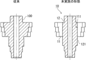
図1は、実施の形態1にかかるシャフト付ヘリカルギヤ10の一例を概略的に示す正面断面図である。なお、図1は、対比のため、従来技術にかかるシャフト付ヘリカルギヤ100も合わせて示されている。また、図1は、シャフト付ヘリカルギヤ10,100のヘリカルギヤ部分の構造がギヤ比に応じて異なることを示している。
(1) Embodiment 1
The first embodiment relates to a helical gear with a shaft with a shaft.
(1-1) Structure of
図1に示されるように、従来技術にかかるシャフト付ヘリカルギヤ100は、シャフトとヘリカルギヤとが一体に成形された構造になっている。
そのため、ギヤ比が異なるシャフト付ヘリカルギヤ100を製造する場合、シャフト付ヘリカルギヤ100全体を造り替える必要がある。
As shown in FIG. 1, the
Therefore, when manufacturing the
これに対して、実施の形態1にかかるシャフト付ヘリカルギヤ10は、ヘリカルギヤ11とシャフト12とを分割し、ヘリカルギヤ11の中央部に形成された貫通穴111にシャフト12を圧入して勘合する構造になっている。
On the other hand, the helical gear with
そのため、ギヤ比が異なるシャフト付ヘリカルギヤ10を製造する場合、シャフト12を共通化し、ヘリカルギヤ11のみを造り替えるだけで良い。
また、シャフト12及びヘリカルギヤ11を別々に製造し、これらを組み合わせれば良いため、シャフト付ヘリカルギヤ10を効率良く製造することができる。
また、ヘリカルギヤ11は、単純形状となるため、例えば、連続定常押出成形法により、安価に製造することができる。ただし、ヘリカルギヤ11の製造方法は、連続定常押出成形法に限定されるものではなく、一般的な歯形加工(ホブやギヤシェーパー等)を用いても良い。
Therefore, when manufacturing the
Moreover, since the
Further, since the
また、シャフト付ヘリカルギヤ10は、ヘリカルギヤ11とシャフト12との勘合部における圧入代を変更することにより、ヘリカルギヤ11の外周面の歯のクラウニングを付与する構造になっている。具体的には、上記勘合部において、シャフト12の長手方向中央部における圧入代を、長手方向両端部における圧入代よりも大きくする。
The helical gear with
従来は、ヘリカルギヤ11のクラウニングを変更する場合、特許文献1に開示された冷間鍛造装置のように、リング型の弾性変形量を微妙に調整する必要があった。また、従来は、ヘリカルギヤ11にクラウニングを付与する場合、まず、クラウニングを有していないヘリカルギヤ11を製造し、その後に、ローリングやシェービング等の後加工を行って、ヘリカルギヤ11にクラウニングを付与することもあった。
これに対して、本実施の形態1は、ヘリカルギヤ11とシャフト12との勘合部における圧入代を変更することにより、ヘリカルギヤ11のクラウニングを容易に付与及び変更することができる。また、このようにしてヘリカルギヤ11のクラウニングを容易に付与できるため、ヘリカルギヤ11の製造後、クラウニングの付与のために、ローリングやシェービング等の後加工を行う必要がなくなる。なお、ヘリカルギヤ11の圧入代の詳細については後で述べる。
Conventionally, when the crowning of the
On the other hand, in the first embodiment, the crowning of the
また、シャフト付ヘリカルギヤ10は、スプライン121でヘリカルギヤ11とシャフト12が圧入され、従来技術にかかるシャフト付ヘリカルギヤ100と同一の機能を発揮する構造としている。
Moreover, the
(1−2)ヘリカルギヤ11の圧入代
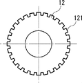
図2A及び図2Bは、実施の形態1にかかるシャフト12の一例を概略的に示す図であり、図2Aは正面断面図、図2Bは図2AのA−A’断面図である。
図2A及び図2Bに示されるように、シャフト12は、外周面にはスプライン121が形成されている。なお、図2Aにおいて、D1を、シャフト12の外径と定義する。
(1-2) Press-fit allowance of the
As shown in FIGS. 2A and 2B, the
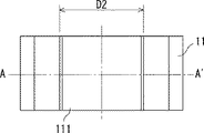
図3A及び図3Bは、実施の形態1にかかるヘリカルギヤ11の一例を概略的に示す図であり、図3Aは正面断面図、図3Bは図3AのA−A’断面図である。
図3A及び図3Bに示されるように、ヘリカルギヤ11は、外周面に歯を有し、中央部に貫通穴111が形成されている。なお、図3Aにおいて、D2を、ヘリカルギヤ11の内径と定義する。
3A and 3B are diagrams schematically illustrating an example of the
As shown in FIGS. 3A and 3B, the
ここで、シャフト12の外径D1は、ヘリカルギヤ11の内径D2よりも大きくなっている。外径D1と内径D2との差分をαと定義する。
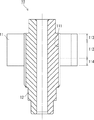
また、図4に示されるように、ヘリカルギヤ11の中央部に形成された貫通穴111にシャフト12を圧入して勘合する。この勘合部において、シャフト12の長手方向の中央部分を長手方向中央部112、長手方向の両端部分を長手方向両端部113,114と定義する。
Here, the outer diameter D1 of the
Further, as shown in FIG. 4, the
上述の通り、シャフト12の外径D1は、ヘリカルギヤ11の内径D2よりも大きく、その差分はαとなっている。そのため、ヘリカルギヤ11とシャフト12との勘合部における長手方向中央部112は、αの圧入代がある。その一方で、上記の勘合部における長手方向両端部113,114は、例えば、圧入代がゼロである。このような圧入代の差があることにより、上記の勘合部における長手方向中央部112は、径の寸法が大きくなる方向に盛り上がる。これにより、ヘリカルギヤ11の外周面の歯には疑似的なクラウニングが付与される。
As described above, the outer diameter D1 of the
上述したように、実施の形態1においては、ヘリカルギヤ11とシャフト12との勘合部における圧入代を変更することにより、ヘリカルギヤ11の外周面の歯のクラウニングを付与する構造になっている。具体的には、上記勘合部において、長手方向中央部112における圧入代を、長手方向両端部113,114における圧入代よりも大きくする。
このように、ヘリカルギヤ11とシャフト12との勘合部における圧入代を変更することにより、ヘリカルギヤ11のクラウニングを容易に付与及び変更することができる。また、このようにしてヘリカルギヤ11のクラウニングを容易に付与できるため、ヘリカルギヤ11の製造後、クラウニングの付与のために、ローリングやシェービング等の後加工を行う必要がなくなる。
As described above, in the first embodiment, the crowning of teeth on the outer peripheral surface of the
Thus, by changing the press-fitting allowance at the fitting portion between the
ここで、実施の形態1において、シャフト12の外径D1及びヘリカルギヤ11の内径D2の寸法は、特に限定されない。外径D1及び内径D2の寸法は、ヘリカルギヤ11にシャフト12を圧入可能で、かつ、ヘリカルギヤ11にクラウニングを付与可能な寸法であれば、任意の寸法で構わない。
Here, in Embodiment 1, the dimensions of the outer diameter D1 of the
また、実施の形態1において、上記勘合部における圧入代は、長手方向中央部112、長手方向両端部113,114の3箇所で変えていたが、これには限定されない。上記勘合部における圧入代は、連続的に曲線のように変化させても良い。また、圧入部の断面形状は、スプライン121とし、その大径を図示し、説明してきたが、小径でも構わないし、スプライン121の大径、小径をつなぐりょう線や、これらの組み合わせ部位でも構わない。また、断面形状そのものが、円弧やだ円でも構わない。
In the first embodiment, the press-fitting allowance in the fitting portion is changed at the three locations of the
(2)実施の形態2
実施の形態2は、遊星歯車機構(プラネタリーギヤ)に用いられ、内周面に歯を有するプラネタリーリングギヤに関するものである。
プラネタリーリングギヤの内周面の歯の成形は、一般的には、ブローチ加工で行い、その後にクラウニングを付与するための加工は行っていないのが現状である。その理由は、プラネタリーリングギヤは、内周面に歯を有するため、ローリングやシェービング等の加工がやりにくいためである。
(2) Embodiment 2
The second embodiment relates to a planetary ring gear that is used in a planetary gear mechanism (planetary gear) and has teeth on an inner peripheral surface.
In general, the teeth on the inner peripheral surface of the planetary ring gear are formed by broaching, and thereafter, processing for imparting crowning is not performed. The reason is that the planetary ring gear has teeth on the inner peripheral surface, so that it is difficult to perform processing such as rolling and shaving.
遊星歯車機構を車両に使用する場合、車両におけるNV(Noise and Vibration)性能の向上を図るためには、プラネタリーリングギヤにクラウニングを付与する構成とすることが好適であるが、その構成とすることでコストの増大が懸念される。
そこで、実施の形態2は、低コストで、プラネタリーリングギヤにクラウニングを付与する構成を提供する。
When the planetary gear mechanism is used in a vehicle, in order to improve the NV (Noise and Vibration) performance in the vehicle, it is preferable to have a configuration in which crowning is applied to the planetary ring gear. There is a concern that the cost will increase.
Therefore, the second embodiment provides a configuration that provides crowning to the planetary ring gear at low cost.
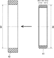
図5は、実施の形態2にかかるプラネタリーリングギヤ41及びケース42の一例を概略的に示す正面断面図である。
図5に示されるように、実施の形態2においては、プラネタリーリングギヤ41とケース42とを分割し、ケース42にプラネタリーリングギヤ41を圧入して勘合する構造になっている。図5において、D1をプラネタリーリングギヤ41の外径と定義し、D2をケース42の内径と定義する。また、ケース42にプラネタリーリングギヤ41を勘合する時の勘合部において、プラネタリーリングギヤ41の軸線方向の中央部分を軸線方向中央部411、軸線方向の両端部分を軸線方向両端部412,413と定義する。
FIG. 5 is a front sectional view schematically showing an example of the
As shown in FIG. 5, in the second embodiment, the
ここで、プラネタリーリングギヤ41の外径D1は、ケース42の内径D2よりも大きくなっている。外径D1と内径D2との差分をαと定義する。
上述の通り、プラネタリーリングギヤ41の外径D1は、ケース42の内径D2よりも大きく、その差分はαとなっている。そのため、プラネタリーリングギヤ41とケース42との勘合部における軸線方向中央部411は、αの圧入代がある。その一方で、上記の勘合部における軸線方向両端部412,413は、例えば、圧入代がゼロである。このような圧入代の差があることにより、上記の勘合部における軸線方向中央部411は、径の寸法が小さくなる方向に縮む。これにより、プラネタリーリングギヤ41の内周面の歯には疑似的なクラウニングが付与される。
Here, the outer diameter D 1 of the
As described above, the outer diameter D1 of the
上述したように、実施の形態2においては、プラネタリーリングギヤ41とケース42との勘合部における圧入代を変更することにより、プラネタリーリングギヤ41の内周面の歯のクラウニングを付与する構造になっている。具体的には、上記勘合部において、軸線方向中央部411における圧入代を、軸線方向両端部412,413における圧入代よりも大きくする。
このように、プラネタリーリングギヤ41とケース42との勘合部における圧入代を変更することにより、プラネタリーリングギヤ41のクラウニングを容易に付与及び変更することができる。
As described above, the second embodiment has a structure in which crowning of teeth on the inner peripheral surface of the
Thus, the crowning of the
また、プラネタリーリングギヤ41のクラウニングの付与及び変更は、プラネタリーリングギヤ41とケース42との勘合部における圧入代を変更するという、低コストな構成で実現することができる。
また、プラネタリーリングギヤ41を、ケース42に圧入する構造とすることで、内周面の歯の歯底部に予圧縮を与えることになり、歯形の強度の向上が図れることも期待される。そのため、プラネタリーリングギヤ41のサイズダウンが可能となり、ユニット全体の小型化にも寄与が可能となる。
Moreover, the provision and change of the crowning of the
Further, by adopting a structure in which the
ここで、実施の形態2において、プラネタリーリングギヤ41の外径D1及びケース42の内径D2の寸法は、特に限定されない。外径D1及び内径D2の寸法は、ケース42にプラネタリーリングギヤ41を圧入可能で、かつ、プラネタリーリングギヤ41にクラウニングを付与可能な寸法であれば、任意の寸法で構わない。
Here, in Embodiment 2, the dimensions of the outer diameter D1 of the
また、実施の形態2において、上記勘合部における圧入代は、軸線方向中央部411、軸線方向両端部412,413の3箇所で変えていたが、これには限定されない。上記勘合部における圧入代は、連続的に曲線のように変化させても良い。
In the second embodiment, the press-fitting allowance at the fitting portion is changed at three locations of the
なお、本発明は上記実施の形態に限られたものではなく、趣旨を逸脱しない範囲で適宜変更することが可能である。 Note that the present invention is not limited to the above-described embodiment, and can be changed as appropriate without departing from the spirit of the present invention.
10 シャフト付ヘリカルギヤ
11 ヘリカルギヤ
111 貫通穴
112 長手方向中央部
113,114 長手方向両端部
12 シャフト
121 スプライン
41 プラネタリーリングギヤ
411 軸線方向中央部
412,413 軸線方向両端部
42 ケース
DESCRIPTION OF
Claims (2)
前記ヘリカルギヤの中央部に形成された貫通穴に前記シャフトを圧入して勘合するステップと、を備え、
前記ヘリカルギヤと前記シャフトとの勘合部において、前記シャフトの長手方向中央部における圧入代を、長手方向両端部における圧入代よりも大きくすることにより、前記ヘリカルギヤの前記歯にクラウニングを付与する、
シャフト付ヘリカルギヤの製造方法。 Separately manufacturing a helical gear having teeth on the outer peripheral surface and a shaft;
Press fitting the shaft into a through hole formed in the central portion of the helical gear, and
In the fitting portion between the helical gear and the shaft, crowning is imparted to the teeth of the helical gear by making the press-fitting allowance at the longitudinal center portion of the shaft larger than the press-fitting allowance at both longitudinal ends.
Manufacturing method of helical gear with shaft.
前記ケースに前記リングギヤを圧入して勘合するステップと、を備え、
前記ケースと前記リングギヤとの勘合部において、前記リングギヤの軸線方向中央部における圧入代を、軸線方向両端部における圧入代よりも大きくすることにより、前記リングギヤの前記歯にクラウニングを付与する、
プラネタリーリングギヤの製造方法。 Separately manufacturing a ring gear having teeth on the inner peripheral surface and a case;
And press-fitting the ring gear into the case for fitting,
In the fitting portion between the case and the ring gear, by making the press-fitting allowance at the axial center part of the ring gear larger than the press-fitting allowance at both axial ends, crowning is imparted to the teeth of the ring gear.
A method of manufacturing a planetary ring gear.
Priority Applications (1)
| Application Number | Priority Date | Filing Date | Title |
|---|---|---|---|
| JP2015241312A JP2017104890A (en) | 2015-12-10 | 2015-12-10 | Method for manufacturing helical gear with shaft |
Applications Claiming Priority (1)
| Application Number | Priority Date | Filing Date | Title |
|---|---|---|---|
| JP2015241312A JP2017104890A (en) | 2015-12-10 | 2015-12-10 | Method for manufacturing helical gear with shaft |
Publications (1)
| Publication Number | Publication Date |
|---|---|
| JP2017104890A true JP2017104890A (en) | 2017-06-15 |
Family
ID=59058350
Family Applications (1)
| Application Number | Title | Priority Date | Filing Date |
|---|---|---|---|
| JP2015241312A Pending JP2017104890A (en) | 2015-12-10 | 2015-12-10 | Method for manufacturing helical gear with shaft |
Country Status (1)
| Country | Link |
|---|---|
| JP (1) | JP2017104890A (en) |
Citations (3)
| Publication number | Priority date | Publication date | Assignee | Title |
|---|---|---|---|---|
| JPS5542713A (en) * | 1978-09-14 | 1980-03-26 | Hitachi Ltd | Crowning forming method of gear by interference |
| JP2001071090A (en) * | 1999-06-30 | 2001-03-21 | Trw Inc | Rack and pinion steering device, and manufacture of helical pinion |
| JP2009236265A (en) * | 2008-03-28 | 2009-10-15 | Mitsuba Corp | Engine starter |
-
2015
- 2015-12-10 JP JP2015241312A patent/JP2017104890A/en active Pending
Patent Citations (3)
| Publication number | Priority date | Publication date | Assignee | Title |
|---|---|---|---|---|
| JPS5542713A (en) * | 1978-09-14 | 1980-03-26 | Hitachi Ltd | Crowning forming method of gear by interference |
| JP2001071090A (en) * | 1999-06-30 | 2001-03-21 | Trw Inc | Rack and pinion steering device, and manufacture of helical pinion |
| JP2009236265A (en) * | 2008-03-28 | 2009-10-15 | Mitsuba Corp | Engine starter |
Similar Documents
| Publication | Publication Date | Title |
|---|---|---|
| US9856945B2 (en) | Planetary gear train of internal engagement type | |
| KR20150138185A (en) | Strain wave gearing device | |
| JP5252127B2 (en) | Ring gear fastening structure | |
| JP5093003B2 (en) | Spline shaft and method for manufacturing spline shaft | |
| WO2011145189A1 (en) | Fastening structure of ring gear | |
| JP6282340B2 (en) | Wave generator for wave gear device and method for manufacturing wave generator | |
| EP2719925A1 (en) | Crimping component, method for joining crimping component, and method for producing crimping component | |
| JP6277895B2 (en) | Torque transmission member and coupling portion between drive shaft and driven shaft | |
| JP2009133415A (en) | Wave gear speed reducer and variable transmission ratio steering device | |
| JP6400200B2 (en) | Wave gear device and wave generator | |
| JP2017104890A (en) | Method for manufacturing helical gear with shaft | |
| CN206555269U (en) | Engine output shaft | |
| JP2009204093A (en) | Pulley structure and belt type continuously variable transmission | |
| KR100970712B1 (en) | Harmonic drive | |
| JP2005201375A (en) | Worm wheel | |
| WO2015029309A1 (en) | Helical gear, method for manufacturing same, and gear device | |
| JP6644608B2 (en) | Plate-integrated rolling bearing | |
| JP2015142956A (en) | Planetary gear and method of producing internal gear thereof | |
| JP6175380B2 (en) | Planetary reducer | |
| US10018196B2 (en) | Rotating body, rotating body material, and method of manufacturing rotating body | |
| JP2020085189A (en) | Fitting structure of shaft member | |
| JP6551125B2 (en) | Gear transmission | |
| KR20090062924A (en) | Parking gear set | |
| JP2016205265A (en) | Torque transmission device and its process of manufacture | |
| JP2015059586A (en) | Trapezoidal tooth trace gear |
Legal Events
| Date | Code | Title | Description |
|---|---|---|---|
| A621 | Written request for application examination |
Free format text: JAPANESE INTERMEDIATE CODE: A621 Effective date: 20171222 |
|
| A131 | Notification of reasons for refusal |
Free format text: JAPANESE INTERMEDIATE CODE: A131 Effective date: 20181002 |
|
| A977 | Report on retrieval |
Free format text: JAPANESE INTERMEDIATE CODE: A971007 Effective date: 20180928 |
|
| A521 | Request for written amendment filed |
Free format text: JAPANESE INTERMEDIATE CODE: A523 Effective date: 20181128 |
|
| A02 | Decision of refusal |
Free format text: JAPANESE INTERMEDIATE CODE: A02 Effective date: 20190507 |