JP2017104519A - Game machine - Google Patents
Game machine Download PDFInfo
- Publication number
- JP2017104519A JP2017104519A JP2016220348A JP2016220348A JP2017104519A JP 2017104519 A JP2017104519 A JP 2017104519A JP 2016220348 A JP2016220348 A JP 2016220348A JP 2016220348 A JP2016220348 A JP 2016220348A JP 2017104519 A JP2017104519 A JP 2017104519A
- Authority
- JP
- Japan
- Prior art keywords
- control unit
- effect
- command
- game
- state
- Prior art date
- Legal status (The legal status is an assumption and is not a legal conclusion. Google has not performed a legal analysis and makes no representation as to the accuracy of the status listed.)
- Pending
Links
Images


Abstract
Description
本発明は、遊技球の入賞によって大当たりの抽選を行うパチンコ遊技機や、遊技媒体の
投入の際の抽選結果を複数リールの停止時に図柄の組み合わせで表示するスロットマシン
等の遊技機に関するものである。
The present invention relates to a gaming machine such as a pachinko gaming machine that draws a jackpot by winning a game ball, or a slot machine that displays a lottery result when a game medium is inserted in a combination of symbols when a plurality of reels are stopped. .
例えば、特許文献1には、可動役物が、開閉動作が可能な開閉部材と、開閉部材の裏面
側に配設される回転体と、可動役物を垂直方向に駆動する第1駆動源と、開閉部材を駆動
する第2駆動源と、回転体を駆動する第3駆動源と、を備えることが開示されている。ま
た、制御手段は、第1駆動源を駆動制御して可動役物を移動させ、また第2駆動源を駆動
制御して開閉部材を開閉動作させ、さらに第3駆動源を駆動制御して回転体を回転させる
ようにすることが開示されている。
For example, in
本発明は、装飾体の動きにより、遊技の興趣性を高めることが可能な遊技機を提供する
ことを目的とする。
An object of this invention is to provide the game machine which can improve the interest property of a game with the motion of a decoration.
上記の目的を達成する本発明は、次のような遊技機として実現される。この遊技機は、
所定の演出を行う遊技機(例えば、パチンコ遊技機100)であって、変位可能であると
ともに回転可能であるように設けられる装飾体(例えば、演出体50A)と、駆動力を発
生させる単一の駆動源(例えば、第1モータM1)と、前記単一の駆動源の駆動力を用い
て前記装飾体の変位および回転を行うための機構(例えば、支持体40A)とを備え、前
記機構は、前記装飾体を第1の位置から第2の位置に移動させ、当該第2の位置にて当該
装飾体が遊技者に第1の面(例えば、第1の面500A)を向けた状態から当該装飾体を
回転させ遊技者に第2の面(例えば、第2の面500B)を向けた状態とした後に当該第
1の面を向け、当該第1の面を向けた当該装飾体を当該第2の位置から当該第1の位置へ
移動させることを特徴とすることができる。
ここで、前記単一の駆動源は、前記装飾体の変位を行う際と前記回転を行う際とで互い
に異なるトルクにて駆動することを特徴とすることができる。
The present invention that achieves the above object is realized as the following gaming machine. This gaming machine
A gaming machine (for example, a pachinko gaming machine 100) that performs a predetermined performance, a decoration body (for example, a
Here, the single drive source may be driven by different torques when the decorative body is displaced and when the rotation is performed.
なお、本欄における上記符号は、本発明の説明に際して例示的に付したものであり、こ
の符号により本発明が減縮されるものではない。
In addition, the said code | symbol in this column is attached | subjected illustratively in the description of this invention, and this invention is not reduced by this code | symbol.
本発明によれば、装飾体の動きにより、遊技の興趣性を高めることが可能な遊技機を提
供することができる。
ADVANTAGE OF THE INVENTION According to this invention, the game machine which can improve the interest property of a game with the motion of a decoration body can be provided.
以下、添付図面を参照して、本発明の実施の形態について詳細に説明する。
〔遊技機の基本構成〕
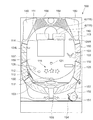
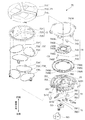
図1は、本実施の形態に係るパチンコ遊技機100の概略正面図である。
図1に示す遊技機の一例としてのパチンコ遊技機100は、遊技者の指示操作により打
ち出された遊技球が入賞すると賞球を払い出すように構成されたものである。このパチン
コ遊技機100は、遊技球が打ち出される遊技盤110と、遊技盤110を囲む枠部材1
50とを備えている。遊技盤110は、枠部材150に着脱自在に取り付けられている。
なお、以下の説明において、図1に示すパチンコ遊技機100の紙面上側と紙面下側と
の方向を上下方向と称し、紙面左側と紙面右側との方向を左右方向と呼ぶ。さらに、図1
に示すパチンコ遊技機100に対して遊技者が遊技をする側を前側と呼び、その逆側を後
側と呼ぶ。
Embodiments of the present invention will be described below in detail with reference to the accompanying drawings.
[Basic configuration of gaming machine]
FIG. 1 is a schematic front view of a
A
50. The
In the following description, the direction of the upper side and the lower side of the paper surface of the
The side where the player plays a game with respect to the
遊技盤110は、前面に、遊技球により遊技を行うための遊技領域111と、下方から
発射された遊技球が上昇して遊技領域111の上部位置へ向かう通路を形成するレール部
材112と、遊技領域111の右側に遊技球を案内する案内部材113とを備えている。
本実施の形態では、遊技者により視認され易い遊技領域111の位置に、演出のための
各種の画像を表示する画像表示部114が配設されている。この画像表示部114は、液
晶ディスプレイ等による表示画面を備え、遊技者によるゲームの進行に伴い、例えば、図
柄抽選結果(図柄変動結果)を遊技者に報知するための装飾図柄を表示したり、キャラク
タの登場やアイテムの出現による演出画像や後述の保留表示を用いた演出画像を表示した
りする。
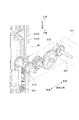
また、遊技盤110の前面に、各種の演出に用いられる可動役物115および盤ランプ
116を備えている。可動役物115は、遊技盤110上で動作することにより各種の演
出を行い、また、盤ランプ116は、発光することで各種の演出を行う。
The
In the present embodiment, an
In addition, a
遊技領域111には、遊技球が落下する方向に変化を与えるための図示しない遊技くぎ
および風車等が配設されている。また、遊技領域111には、入賞や抽選に関する種々の
役物が所定の位置に配設されている。また、遊技領域111には、遊技領域111に打ち
出された遊技球のうち入賞口に入賞しなかったものを遊技領域111の外に排出する排出
口117が配設されている。
In the
本実施の形態では、入賞や抽選に関する種々の役物として、遊技球が入賞すると特別図
柄抽選(大当たり抽選)が始動する第1始動口121および第2始動口122と、遊技球
が通過すると普通図柄抽選(開閉抽選)が始動する始動ゲート(以下、単にゲートと呼ぶ
)124と、が遊技盤110に配設されている。なお、図1において、ゲート124は、
遊技領域111の左右にそれぞれ設けられており、左側のゲート124は124Lと記載
し、右側のゲート124は124Rと記載している。また、ここにいう第1始動口121
および第2始動口122とは、予め定められた1の特別図柄表示器の作動契機となる入賞
口をいう。具体的には、第1始動口121および第2始動口122には、入賞の際に遊技
球の通過を検知するスイッチ(後述の第1始動口スイッチ211および第2始動口スイッ
チ212)が設けられている。そして、第1始動口121または第2始動口122に遊技
球が入賞した際にこのスイッチが遊技球の通過を検知することが、特別図柄表示器を作動
させる契機となる。
In the present embodiment, as various functions related to winning and lottery, a special symbol lottery (a jackpot lottery) starts when a game ball wins, and it is normal when a game ball passes. A start gate (hereinafter simply referred to as a gate) 124 for starting a symbol lottery (open / close lottery) is disposed on the
The left gate 124 is described as 124L, and the right gate 124 is described as 124R. Also, the
And the
第2始動口122は、チューリップの花の形をした一対の羽根が電動ソレノイドにより
開閉すると共に点灯する普通電動役物としての電動チューリップ(開閉部材)123を備
えている。電動チューリップ123は、羽根が閉じていると、遊技球が第2始動口122
へ入り難い一方で、羽根が開くと第2始動口122の入口が拡大して遊技球が第2始動口
122へ入り易くなるように構成されている。そして、電動チューリップ123は、普通
図柄抽選に当選すると、点灯ないし点滅しながら羽根が規定時間(例えば0.15秒ない
し1.8秒間)および規定回数(例えば1回ないし3回)だけ開く。
The
On the other hand, it is configured such that when the blades are opened, the entrance of the
パチンコ遊技機100は、遊技状態として、大当たり抽選の当選確率に基づき、当選確
率の低い低確率状態と、低確率状態よりも当選確率の高い高確率状態とを有している。そ
して、所定の条件において低確率状態と高確率状態とのいずれかの状態に制御される。ま
た、パチンコ遊技機100は、第2始動口122への入賞機会が少ない時短無状態と、時
短無状態よりも第2始動口122への入賞機会が多い時短状態とを有している。そして、
所定の条件において、時短無状態と、時短状態とのいずれかの状態に制御される。時短状
態とは、たとえば、普通図柄抽選の当たり当選確率を高確率にする、普通図柄変動時間を
短縮する、あるいは電動チューリップ123の開時間を延長する、のいずれか一つまたは
複数の組合せによって制御される遊技状態である。なお、時短状態では、特別図柄の特別
図柄変動時間が短縮されていてもよい。
The
Under a predetermined condition, the state is controlled to be either a timeless state or a timeless state. The short-time state is controlled by any one or a combination of, for example, increasing the probability of winning the normal symbol lottery, reducing the normal symbol variation time, or extending the opening time of the
また、本実施の形態では、入賞や抽選に関するその他の役物として、特別図柄抽選の結
果に応じて開放する特別電動役物としての大入賞口125と、遊技球が入賞しても抽選を
行わない普通入賞口126と、が遊技盤110に配設されている。
本実施の形態では、遊技盤110の右下の位置に、抽選結果や保留数に関する表示を行
う表示器130が配設されている。
Also, in this embodiment, as other prizes and lottery items, a lottery is performed even if a game ball wins a grand prize opening 125 as a special electric bonus that opens according to the result of the special symbol lottery. An ordinary winning
In the present embodiment, a
また、遊技盤110の裏面には、特別図柄の当選の判定等を行う遊技制御基板、演出を
統括的に制御する演出制御基板、画像および音による演出を制御する画像制御基板、各種
のランプおよび可動役物115による演出を制御するランプ制御基板などの図示しない各
種の基板等が取り付けられる。また、遊技盤110の裏面には、供給された24VのAC
電源をDC電源に変換して各種の基板等に出力するスイッチング電源(不図示)が配設さ
れている。
Also, on the back side of the
A switching power supply (not shown) that converts the power supply into a DC power supply and outputs it to various substrates and the like is provided.
枠部材150は、遊技者がハンドル151に触れてレバー152を時計方向に回転させ
る操作を行うとその操作角度に応じた打球力にて遊技球を所定の時間間隔(例えば1分間
に100個)で電動発射する発射装置(不図示)を備えている。また、枠部材150は、
遊技者のレバー152による操作と連動したタイミングで発射装置に遊技球を1つずつ順
に供給する供給装置(不図示)と、供給装置が発射装置に供給する遊技球を一時的に溜め
ておく皿153と、を備えている。この皿153には、例えば払い出しユニットによる払
出球が払い出される。
なお、本実施の形態では、皿153を上下皿一体で構成しているが、上皿と下皿とを分
離する構成例も考えられる。また、発射装置のハンドル151を所定条件下で発光させる
構成例も考えられる。
When the player touches the
A supply device (not shown) for sequentially supplying game balls to the launching device one by one at a timing interlocked with the operation of the player's
In the present embodiment, the
また、枠部材150は、発射装置のハンドル151に遊技者が触れている状態であって
も遊技球の発射を一時的に停止させるための停止ボタン154と、皿153に溜まってい
る遊技球を箱(不図示)に落下させて取り出すための取り出しボタン155と、を備えて
いる。
また、枠部材150は、パチンコ遊技機100の遊技状態や状況を告知したり各種の演
出を行ったりするスピーカ156および枠ランプ157を備えている。スピーカ156は
、楽曲や音声、効果音による各種の演出を行う。枠ランプ157は、LED等の発光体で
構成され、点灯・点滅によるパターンや発光色の違い等で光による各種の演出を行う。な
お、枠ランプ157については、光の照射方向を変更する演出を行うことを可能にする構
成例が考えられる。
また、枠部材150は、遊技盤110を遊技者と隔てるともに、パチンコ遊技機100
の外面を構成する透明板90(図34参照)を備えている。
Further, the
Further, the
Further, the
The transparent plate 90 (refer FIG. 34) which comprises the outer surface is provided.
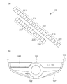
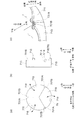
図2は、本実施の形態に係るパチンコ遊技機100を説明する図であり、図2(a)は
、遊技盤110の右下に配設された表示器130の一例を示す拡大図であり、図2(b)
は、パチンコ遊技機100の部分平面図である。
パチンコ遊技機100の表示器130は、図2(a)に示すように、第1始動口121
の入賞に対応して作動する第1特別図柄表示器221と、第2始動口122の入賞に対応
して作動する第2特別図柄表示器222と、ゲート124の通過に対応して作動する普通
図柄表示器223と、を備えている。第1特別図柄表示器221は、第1始動口121の
入賞に基づき、特別図柄を変動表示した後に停止させて抽選結果を表示する。第2特別図
柄表示器222は、第2始動口122の入賞に基づき、特別図柄を変動表示した後に停止
させて抽選結果を表示する。普通図柄表示器223は、遊技球がゲート124を通過した
ことに基づき、普通図柄を変動表示した後に停止させて抽選結果を表示する。本実施の形
態では、第1特別図柄表示器221、第2特別図柄表示器222は、各々LEDを配列し
た表示装置で構成され、その点灯態様によって特別図柄抽選の抽選結果が表示される。同
様に、普通図柄表示器223も、LEDを配列した表示装置で構成され、その点灯態様に
よって普通図柄抽選の抽選結果が表示される。
FIG. 2 is a view for explaining the
These are partial plan views of the
As shown in FIG. 2A, the
The first
また、表示器130は、第1特別図柄表示器221での保留に対応して作動する第1特
別図柄保留表示器218と、第2特別図柄表示器222での保留に対応して作動する第2
特別図柄保留表示器219と、普通図柄表示器223での保留に対応して作動する普通図
柄保留表示器220と、を備えている。本実施の形態では、第1特別図柄保留表示器21
8、第2特別図柄保留表示器219および普通図柄保留表示器220は、各々LEDを配
列した表示装置で構成され、その点灯態様によって保留数が表示される。
In addition, the
A special
8. The second special
ここで、保留について説明する。特別図柄の変動表示動作中(入賞1回分の変動表示が
行なわれている間)にさらに第1始動口121または第2始動口122に遊技球が入賞し
た場合、特別図柄が変動中であるために、後の入賞に基づく特別図柄の変動表示動作を開
始することができない。そのため、後の入賞は規定個数(例えば4個)を限度に記憶され
、その入賞した遊技球に対する特別図柄を始動させるための権利が、先に入賞した遊技球
に対する変動表示動作が終了するまで、保留される。
なお、普通図柄に関しても、特別図柄と同様の処理を行う。このような保留がなされて
いることおよびその保留の数(未変動数)が、第1特別図柄保留表示器218、第2特別
図柄保留表示器219および普通図柄保留表示器220に表示される。
Here, the hold will be described. If a game ball wins in the
For normal symbols, the same processing as for special symbols is performed. The fact that such a hold has been made and the number of hold (unchanged number) are displayed on the first special
さらに、表示器130は、パチンコ遊技機100の状態を表示する状態表示器224を
備えている。本実施の形態では、状態表示器224は、3個のLEDを配列した表示装置
で構成されている。3個のLEDのうち1つは、パチンコ遊技機100の状態が、特別図
柄抽選の当選確率が高確率である高確率状態となっているか否かを点灯により報知するも
のである。また、他の1つは、パチンコ遊技機100の状態が、第2始動口122に入賞
しやすい時短状態となっているか否かを点灯により報知するものである。さらに他の1つ
は、右打ちすることによって(遊技球の打球力を変更することによって)遊技者に有利な
状態となっているか否かを点灯により報知するものである。
Furthermore, the
なお、状態表示器224が表示するパチンコ遊技機100の状態は上記の例に限らず、
他の状態を表示することができる。例えばパチンコ遊技機100の状態として低確率状態
よりも当選確率が高く高確率状態よりは当選確率が低い中確率状態が設定される場合、状
態表示器224は、中確率状態となっているか否かを点灯により報知しても良い。
In addition, the state of the
Other states can be displayed. For example, when the state of the
また、表示器130は、特別図柄抽選の抽選結果に応じて行われる大当たり遊技におい
て大入賞口125が作動される際のラウンド数を表示するラウンド数表示器225を備え
ている。なお、大当たり遊技については後述する。ラウンド数表示器225は、LEDを
配列した表示装置で構成され、その点灯態様によって大当たり遊技における大入賞口12
5の作動ラウンド数が表示される。
In addition, the
The number of 5 operating rounds is displayed.
パチンコ遊技機100の枠部材150は、遊技者が演出に対する入力を行うための入力
装置を備えている。図2(b)に示すように、本実施の形態では、入力装置の一例として
、演出ボタン161と、演出ボタン161に隣接し、略十字に配列された複数のキーから
なる演出キー162と、が枠部材150に配設されている。図示の例において、遊技者は
、例えば、十字に配列された4つのキーからなる演出キー162を操作することにより、
画像表示部114に表示されている複数の画像の何れかを指示することが可能であり、ま
た、演出ボタン161を操作することにより、指示した画像を選択することが可能である
。また、入力装置の形態としては、図示した演出ボタン161および演出キー162の他
、レバーやダイヤル等、演出の内容等に応じて様々な入力形態を採用することができる。
The
Any of a plurality of images displayed on the
〔制御ユニットの構成〕
次に、パチンコ遊技機100での動作制御や信号処理を行う制御ユニットについて説明
する。
図3は、制御ユニットの内部構成を示すブロック図である。図3に示すように、制御ユ
ニットは、メイン制御手段として、特別図柄の当選の判定等を行う遊技制御部200を備
えている。また、サブ制御手段として、演出を統括的に制御する演出制御部300と、画
像および音響を用いた演出を制御する画像/音響制御部310と、各種のランプおよび可
動役物115を用いた演出を制御するランプ制御部320と、払出球の払い出し制御を行
う払出制御部330と、を備えている。
[Configuration of control unit]
Next, a control unit that performs operation control and signal processing in the
FIG. 3 is a block diagram showing an internal configuration of the control unit. As shown in FIG. 3, the control unit includes a
前述したように、遊技制御部200、演出制御部300、画像/音響制御部310、ラ
ンプ制御部320、および払出制御部330各々は、遊技盤110の後面に配設されたメ
イン基板としての遊技制御基板、サブ基板としての演出制御基板、画像制御基板、ランプ
制御基板、および払出制御基板において個別に構成されている。
As described above, the
〔遊技制御部の構成・機能〕
遊技制御部200は、特別図柄の当選の判定等を行う際の演算処理を行うCPU201
と、CPU201にて実行されるプログラムや各種データ等が記憶されたROM202と
、CPU201の作業用メモリ等として用いられるRAM203と、を備えている。
遊技制御部200は、第1始動口121または第2始動口122に遊技球が入賞すると
特別図柄抽選を行い、その抽選結果を演出制御部300に送る。また、高確率状態と低確
率状態の変更情報、時短無状態と時短状態の変更情報を演出制御部300に送る。
さらに、遊技制御部200は、普通図柄抽選の当たり当選確率を高確率にする、普通図
柄変動時間を短縮する、あるいは電動チューリップ123の開時間を延長する制御を行う
。また、遊技制御部200は、遊技球が連続的に第1始動口121または第2始動口12
2へ入賞したときの未変動分の限度個数(例えば4個)までの保留や、遊技球が連続的に
ゲート124を通過したときの未変動分の限度個数(例えば4個)までの保留を設定する
。
さらにまた、遊技制御部200は、特別図柄抽選の結果に応じて、特別電動役物である
大入賞口125が所定条件(例えば29.5秒経過または遊技球10個の入賞)を満たす
まで開状態を維持するラウンドを所定回数だけ繰り返すように制御する。さらには、大入
賞口125が開く際の開閉動作間隔を制御する。
[Configuration and function of game control unit]
The
A
When the game ball wins the
Further, the
Hold up to the limit number (for example, 4) of the unchangeable amount when winning 2 and hold to the limit number (for example, 4) of the unchangeable amount when the game ball passes through the gate 124 continuously. Set.
Furthermore, the
さらに、遊技制御部200は、第1始動口121、第2始動口122、大入賞口125
および普通入賞口126に遊技球が入賞すると、遊技球が入賞した場所に応じて1つの遊
技球当たり所定数の賞球を払い出すように、払出制御部330に対する指示を行う。例え
ば、第1始動口121に遊技球が入賞すると3個の賞球、第2始動口122に遊技球が入
賞すると4個の賞球、大入賞口125に遊技球が入賞すると13個の賞球、普通入賞口1
26に遊技球が入賞すると10個の賞球をそれぞれ払い出すように、払出制御部330に
指示命令(コマンド)を送る。なお、ゲート124を遊技球が通過したことを検出しても
、それに連動した賞球の払い出しは払出制御部330に指示しない。
払出制御部330が遊技制御部200の指示に従って賞球の払い出しを行った場合には
、遊技制御部200は、払い出した賞球の個数に関する情報を払出制御部330から取得
する。それにより、払い出した賞球の個数を管理する。
Furthermore, the
When a game ball wins the
When a game ball wins in 26, an instruction command (command) is sent to the
When the
遊技制御部200には、検知手段として、図3に示すように、第1始動口121への遊
技球の入賞を検出する第1始動口検出部(第1始動口スイッチ(SW))211と、第2
始動口122への遊技球の入賞を検出する第2始動口検出部(第2始動口スイッチ(SW
))212と、電動チューリップ123を開閉する電動チューリップ開閉部213と、ゲ
ート124への遊技球の通過を検出するゲート検出部(ゲートスイッチ(SW))214
と、が接続されている。
さらに、遊技制御部200には、大入賞口125への遊技球の入賞を検出する大入賞口
検出部(大入賞口スイッチ(SW))215と、大入賞口125を閉状態と突出傾斜した
開状態とに設定する大入賞口開閉部216と、普通入賞口126への遊技球の入賞を検出
する普通入賞口検出部(普通入賞口スイッチ(SW))217と、が接続されている。
As shown in FIG. 3, the
A second start port detector (second start port switch (SW
)) 212; an electric tulip opening /
And are connected.
Further, the
また、遊技制御部200には、特別図柄の変動中に第1始動口121へ入賞した未変動
分の保留個数を限度個数内(例えば4個)で表示する第1特別図柄保留表示器218と、
特別図柄の変動中に第2始動口122へ入賞した未変動分の保留個数を限度個数内で表示
する第2特別図柄保留表示器219と、普通図柄の変動中にゲート124を通過した未変
動分の保留個数を限度個数内で表示する普通図柄保留表示器220と、が接続されている
。
さらに、遊技制御部200には、第1始動口121への遊技球の入賞により行われる特
別図柄の変動表示および特別図柄抽選の結果を表示する第1特別図柄表示器221と、第
2始動口122への遊技球の入賞により行われる特別図柄の変動表示および特別図柄抽選
の結果を表示する第2特別図柄表示器222と、普通図柄の変動表示および普通図柄抽選
の結果を表示する普通図柄表示器223と、パチンコ遊技機100の状態を表示する状態
表示器224と、が接続されている。
In addition, the
A second special
Further, the
そして、第1始動口スイッチ211、第2始動口スイッチ212、ゲートスイッチ21
4、大入賞口スイッチ215および普通入賞口スイッチ217にて検出された検出信号が
、遊技制御部200に送られる。また、遊技制御部200からの制御信号が、電動チュー
リップ開閉部213、大入賞口開閉部216、第1特別図柄保留表示器218、第2特別
図柄保留表示器219、普通図柄保留表示器220、第1特別図柄表示器221、第2特
別図柄表示器222、普通図柄表示器223および状態表示器224に送られる。それに
より、遊技制御部200は、上記した払い出し賞球数に関連する各種制御を行う。
The first
4. The detection signals detected by the big
さらに、遊技制御部200には、ホールに設置されたホストコンピュータ(不図示)に
対して各種の情報を送信する盤用外部情報端子基板350が接続されている。そして、遊
技制御部200は、払出制御部330から取得した、払い出した賞球数に関する情報や遊
技制御部200の状態等を示す情報を、盤用外部情報端子基板350を介してホストコン
ピュータに送信する。
Further, a board external
〔演出制御部の構成・機能〕
演出制御部300は、演出を制御する際の演算処理を行うCPU301と、CPU30
1にて実行されるプログラムや各種データ等が記憶されたROM302と、CPU301
の作業用メモリ等として用いられるRAM303と、日時を計測するリアルタイムクロッ
ク(RTC)304と、を備えている。
演出制御部300は、例えば遊技制御部200から送られる特別図柄抽選での当選か否
かの判定結果および変動パターンに基づいて、演出内容を設定する。その際、演出ボタン
161または演出キー162を用いたユーザからの操作入力を受けて、操作入力に応じた
演出内容を設定する場合もある。この場合、例えば演出ボタン161等のコントローラ(
不図示)から操作に応じた信号(操作信号)を受け付け、この操作信号により識別される
操作内容を演出の設定に反映させる。
また、演出制御部300は、遊技が所定期間中断された場合には、演出の一つとして客
待ち用の画面表示の設定を指示する。
さらには、演出制御部300は、遊技制御部200より受信した高確率状態と低確率状
態の変更情報、時短無状態と時短状態の変更情報に基づいて演出内容を設定する。
また、演出制御部300は、設定した演出内容の実行を指示するコマンドを画像/音響
制御部310およびランプ制御部320に送る。
[Configuration and function of production control unit]
The
ROM 302 storing programs executed in 1 and various data, and
A
The
A signal (operation signal) corresponding to the operation is received from (not shown), and the operation content identified by this operation signal is reflected in the setting of the effect.
In addition, when the game is interrupted for a predetermined period, the
Furthermore, the
In addition, the
〔画像/音響制御部の構成・機能〕
画像/音響制御部310は、演出内容を表現する画像および音響を制御する際の演算処
理を行うCPU311と、CPU311にて実行されるプログラムや各種データ等が記憶
されたROM312と、CPU311の作業用メモリ等として用いられるRAM313と
、VDP(Video Display Processor)314と、CGROM315と、SNDROM3
16とを備えている。
[Configuration / Function of Image / Sound Control Unit]
The image / sound control unit 310 is a
16.
そして、画像/音響制御部310は、演出制御部300から送られたコマンドに基づい
て、画像表示部114に表示する画像およびスピーカ156から出力する音響を制御する
。
具体的には、CGROM315には、画像表示部114において遊技中に表示する図柄
画像や背景画像、遊技者に抽選結果を報知するための装飾図柄、遊技者に予告演出を表示
するためのキャラクタやアイテム等といった画像データが記憶されている。また、SND
ROM316には、画像データと同期させて、または画像データとは独立にスピーカ15
6から出力させる楽曲や音声、さらにはジングル等の効果音等といった各種音響データが
記憶されている。
CPU311は、演出制御部300から送られた保留数コマンドもしくは変動開始コマ
ンドに基づいて、アニメーションパターンの解析や、描画に関するコマンドをまとめたデ
ィスプレイリストの作成、およびディスプレイリストのVDP314への送信などを行う
。
Then, the image / sound control unit 310 controls the image displayed on the
Specifically, the
The
Various acoustic data such as music and sound to be output from 6 and sound effects such as jingles are stored.
The
VDP314は、CPU311から受信したディスプレイリストに基づいて、CGRO
M315やSNDROM316にそれぞれ記憶された画像データや音響データ読み出す。
さらには、VDP314は、読み出した画像データを用いて背景画像表示、図柄画像表示
、図柄画像変動、およびキャラクタ/アイテム表示等のための描画処理と、読み出した音
響データを用いた音声処理とを行う。そして、VDP314は、描画処理された画像デー
タにより画像表示部114での画面表示を制御する。また、VDP314は、音声処理さ
れた音響データによりスピーカ156から出力される音響を制御する。
なお、本実施の形態では、VDP314が描画処理に併せて音声処理も行うよう構成し
ているが、これに限定されず、音声処理を専用で行うプロセッサを別途設けても構わない
。
Based on the display list received from the
The image data and sound data stored in the M315 and
Furthermore, the VDP 314 performs drawing processing for background image display, symbol image display, symbol image variation, character / item display, and the like, and audio processing using the read acoustic data, using the read image data. . The VDP 314 controls screen display on the
In the present embodiment, the VDP 314 is configured to perform audio processing in addition to the drawing processing. However, the present invention is not limited to this, and a processor that performs dedicated audio processing may be provided separately.
〔ランプ制御部の構成・機能〕
ランプ制御部320は、盤ランプ116や枠ランプ157の発光、および可動役物11
5の動作を制御する際の演算処理を行うCPU321と、CPU321にて実行されるプ
ログラムや各種データ等が記憶されたROM322と、CPU321の作業用メモリ等と
して用いられるRAM323と、を備えている。
そして、ランプ制御部320は、演出制御部300から送られたコマンドに基づいて、
盤ランプ116や枠ランプ157の点灯/点滅や発光色等を制御する。また、可動役物1
15の動作を制御する。
[Configuration and function of lamp control unit]
The
5, a
And the
The lighting / flashing of the
15 operations are controlled.
具体的には、ランプ制御部320のROM322には、演出制御部300にて設定され
る演出内容に応じた盤ランプ116や枠ランプ157での点灯/点滅パターンデータおよ
び発光色パターンデータ(発光パターンデータ)が記憶されている。CPU321は、R
OM322に記憶された発光パターンデータの中から、演出制御部300から送られたコ
マンドに対応したものを選択して読み出す。そして、ランプ制御部320は、読み出した
発光パターンデータにより盤ランプ116や枠ランプ157の発光を制御する。
また、ランプ制御部320のROM322には、演出制御部300にて設定される演出
内容に応じた可動役物115の動作パターンデータが記憶されている。CPU321は、
可動役物115に対しては、読み出した動作パターンデータによりその動作を制御する。
Specifically, the
From the light emission pattern data stored in the
The
The operation of the
〔払出制御部の構成・機能〕
払出制御部330は、払出球の払い出しを制御する際の演算処理を行うCPU331と
、CPU331にて実行されるプログラムや各種データ等が記憶されたROM332と、
CPU331の作業用メモリ等として用いられるRAM333と、を備えている。
そして、払出制御部330は、遊技制御部200から送られたコマンドに基づいて、払
出球の払い出しを制御する。
具体的には、払出制御部330は、遊技制御部200から、遊技球が入賞した場所(第
1始動口121等)に応じた所定数の賞球を払い出すコマンドを取得する。そして、コマ
ンドに指定された数だけの賞球を払い出すように払出駆動部334を制御する。ここでの
払出駆動部334は、遊技球の貯留部から遊技球を送り出す駆動モータで構成される。
[Configuration and function of payout control unit]
The
And a
The
Specifically, the
また、払出制御部330には、払出駆動部334により遊技球の貯留部から実際に払い
出された賞球の数を検出する払出球検出部335と、貯留部(不図示)での遊技球の貯留
の有無を検出する球有り検出部336と、遊技者が遊技する際に使用する遊技球や払い出
された賞球が保持される皿153が満タン状態に有るか否かを検出する満タン検出部33
7と、が接続されている。そして、払出制御部330は、払出球検出部335、球有り検
出部336および満タン検出部337にて検出された検出信号を受け取り、これらの検出
信号に応じた所定の処理を行う。
さらに、払出制御部330には、ホールに設置されたホストコンピュータに対して各種
の情報を送信する枠用外部情報端子基板340が接続されている。そして、払出制御部3
30は、例えば払出駆動部334に対して払い出すように指示した賞球数に関する情報や
払出球検出部335にて検出された実際に払い出された賞球数に関する情報等を枠用外部
情報端子基板340を介してホストコンピュータに送信する。また、遊技制御部200に
対しても、同様の情報を送信する。
The
7 are connected. The
Further, the
30 indicates, for example, information on the number of prize balls instructed to be paid out to the payout driving unit 334, information on the number of prize balls actually paid out detected by the payout
〔遊技制御部の機能構成〕
続いて、遊技制御部200の機能構成を説明する。
図4は、遊技制御部200の機能構成を示すブロック図である。図4に示すように、遊
技制御部200は、各種抽選処理を実行する機能部として、乱数取得部231と、普通図
柄判定部232と、特別図柄変動制御部233と、特別図柄判定部234と、普通図柄変
動制御部236と、を備えている。
また、遊技制御部200は、特別図柄変動に伴う処理を実行する機能部として、変動パ
ターン選択部235を備えている。
さらに、遊技制御部200は、各種役物の動作制御や賞球等に関するデータ処理を実行
する機能部として、大入賞口動作制御部237と、電動チューリップ動作制御部238と
、賞球処理部239と、出力制御部240と、乱数制御部241と、を備えている。
[Functional configuration of game control unit]
Next, the functional configuration of the
FIG. 4 is a block diagram showing a functional configuration of the
In addition, the
In addition, the
乱数取得部231は、第1始動口121や第2始動口122に遊技球が入賞した場合に
、特別図柄に関する乱数の取得を行う。具体的には、所定の範囲の数値の中から一つの数
値(乱数値)が選択(取得)されて、特別図柄判定部234による判定に用いられる。
乱数取得部231は、ゲート124を遊技球が通過した場合に、普通図柄に関する乱数
の取得を行う。具体的には、所定の範囲の数値の中から一つの数値(乱数値)が選択(取
得)されて、普通図柄判定部232による判定に用いられる。
特別図柄変動制御部233は、特別図柄の抽選が行われた場合に、その抽選結果に応じ
て特別図柄の変動を制御する。
The random
The random
The special symbol
特別図柄判定部234は、特別図柄の変動開始時に、図17に示すような乱数テーブル
を用いて、その抽選結果が「大当たりか否か」、「大当たりに当選した場合の大当たりの
種類」、「大当たりに当選していない場合での小当たりかはずれか」を判定する。すなわ
ち、乱数取得部231は、検知手段である第1始動口スイッチ211または第2始動口ス
イッチ212により遊技球の通過が検知されたことを契機として特別図柄に関する乱数値
を取得し、特別図柄判定部234は、取得した乱数値に基づいて、遊技者にとって有利な
特別遊技(大当たり遊技等)を行うか否かを判定する。なお、前述した特別図柄の抽選(
大当たり抽選)は、乱数取得部231および特別図柄判定部234における処理のことを
いう。
The special
The “hit lottery” refers to processing in the random
ここで、「大当たり」は、大当たり遊技の終了後に発生する遊技状態に応じて複数の種
類に分けられる。具体的には、時短無状態か時短状態か、および高確率状態か低確率状態
かの組み合わせによって大当たりの種類が決まる。すなわち、大当たり遊技の終了後に発
生する遊技状態に基づく大当たりの種類としては、大当たり遊技の終了後に、時短状態お
よび高確率状態の両方の状態を有する高確率時短遊技状態となる大当たり(以下、高確率
時短遊技状態の大当たり)、時短状態および低確率状態の両方の状態を有する低確率時短
遊技状態となる大当たり(以下、低確率時短遊技状態の大当たり)、時短無状態および高
確率状態の両方の状態を有する高確率時短無遊技状態となる大当たり(以下、高確率時短
無遊技状態の大当たり)、時短無状態および低確率状態の両方の状態を有する低確率時短
無遊技状態となる大当たり(以下、低確率時短無遊技状態の大当たり)が有り得る。これ
らの大当たりは、各々個別の特別図柄に対応付けられており、特別図柄抽選において当選
した特別図柄の種類に応じて大当たりの種類が確定する。
Here, the “hit” is divided into a plurality of types according to the gaming state that occurs after the end of the jackpot game. Specifically, the type of jackpot is determined depending on the combination of the short-time state or the short-time state and the high-probability state or the low-probability state. In other words, the type of jackpot based on the gaming state that occurs after the end of the jackpot game is a jackpot that becomes a high probability short-time gaming state having both a short-time state and a high-probability state after the jackpot game ends (hereinafter, high probability A jackpot that becomes a low probability short-game state with both a short-time state and a low-probability state (hereinafter, a jackpot of a low-probability short-game state), both a short-time non-state state and a high-probability state A jackpot that becomes a low probability short-time non-game state that has both a short-time no-game state and a low-probability state that has both a short-time and low-probability state There is a possibility of a jackpot of probable short gameless state). Each of these jackpots is associated with an individual special symbol, and the type of jackpot is determined according to the type of special symbol won in the special symbol lottery.
また、「大当たり」は、大当たり遊技の時間が長く多量の遊技球の払い出しが期待でき
る大当たりと、大当たり遊技の時間が短く遊技球の払い出しがほとんど期待できない大当
たりとに分けられる場合がある。前者は「長当たり」と呼ばれ、後者は「短当たり」と呼
ばれる。例えば、「長当たり」では、大入賞口125の開状態が所定条件(例えば29.
5秒経過または10個の遊技球の入賞)を満たすまで維持されるラウンドが所定回数(例
えば15回)繰り返される。また、「短当たり」では、一定時間(例えば0.1秒)だけ
大入賞口125が開状態となるラウンドが所定回数(例えば15回)繰り返される。
In addition, the “hit” may be divided into a jackpot that can be expected to pay out a large amount of game balls for a long time, and a jackpot that can be expected to pay out a short amount of game balls. The former is called “long hit” and the latter is called “short hit”. For example, in “long hit”, the open state of the special winning
The round that is maintained until 5 seconds have passed or 10 game balls have been won) is repeated a predetermined number of times (for example, 15 times). In the “short win”, a round in which the special winning
また、大当たりに当選していない場合の「小当たり」は、例えば0.1秒だけ大入賞口
125が開状態となる態様が所定回数(例えば15回)行われる小当たり遊技が行われる
。なお、小当たり当選時には、小当たり遊技が終了した後においても小当たり当選前の遊
技状態を継続する。すなわち、小当たり当選時の遊技状態が高確率時短遊技状態である場
合には、小当たり遊技の終了後においても高確率時短遊技状態が継続され、遊技状態は移
行しない。同様に、小当たりの当選時の遊技状態が低確率時短無遊技状態である場合には
、小当たり遊技の終了後においても低確率時短無遊技状態が継続され、遊技状態は移行し
ない。
また、「小当たり」は、「はずれ」の一種であり、遊技者に有利となる上記の遊技状態
の何れも設定されない。
In addition, in the case of “small winning” when the big winning is not won, for example, a small winning game is performed in which the big winning
Further, “small hit” is a kind of “out of game”, and none of the above gaming states that are advantageous to the player is set.
変動パターン選択部235は、第1特別図柄表示器221や第2特別図柄表示器222
にて表示する特別図柄の変動パターン(変動時間)を選択する。ここでは、変動パターン
選択部235は、大当たり遊技を行うか否かの判定結果およびリーチを行うか否かの判定
結果等に基づいて、変動パターンを決定する。そして、変動パターン選択部235により
選択された変動パターンに基づいて、特別図柄変動制御部233が特別図柄の変動を制御
する。変動パターン選択部235および特別図柄変動制御部233の動作の詳細について
は後述する。
ここで、「リーチ」とは、後述する装飾図柄において遊技者に大当たりを期待させるた
めの演出である。
The variation
Select the variation pattern (variation time) of the special symbol displayed at. Here, the variation
Here, “reach” is an effect for causing a player to expect a big hit in a decorative pattern to be described later.
普通図柄判定部232は、普通図柄の抽選が行われた場合に、普通図柄の抽選結果が「
当選かはずれであるか」を判定する。
普通図柄変動制御部236は、普通図柄の抽選結果に応じて、普通図柄の変動を制御す
る。
電動チューリップ動作制御部238は、普通図柄の抽選により「当選」と判定された場
合には、電動チューリップ123を規定時間および規定回数だけ開放し、第2始動口12
2に遊技球が入賞容易となる状態を発生させる。また、「はずれ」と判定された場合には
、電動チューリップ123のこのような開放状態を発生させない。
When the normal symbol lottery is performed, the normal
It is judged whether or not it is a winner.
The normal symbol
The electric tulip
2. A state in which a game ball is easy to win is generated. Further, when it is determined as “displacement”, such an open state of the
大入賞口動作制御部237は、大入賞口125の開放動作を制御する。
賞球処理部239は、入賞や抽選に関する種々の役物への入賞個数の管理および入賞に
応じた賞球の払い出しの制御用コマンドをセットする。
出力制御部240は、遊技制御部200から演出制御部300および払出制御部330
へ制御用コマンドの出力を制御する。
乱数制御部241は、メイン制御手段による処理で用いられる各種の乱数値の更新を制
御する。
The special winning opening
The prize
The
Controls the output of control commands.
The random
〔遊技機の基本動作〕
次に、パチンコ遊技機100の基本動作を説明する。
パチンコ遊技機100の遊技制御部200は、電源が投入されると、起動時の基本処理
として、各種装置の初期化や初期設定を行う。そして、基本処理を行った後、遊技制御部
200は、遊技の進行に関する一連の処理である主制御処理を繰り返し実行する。また、
電源を遮断する際には、遊技制御部200は、一連の電源遮断時処理を実行する。
[Basic operation of gaming machine]
Next, the basic operation of the
When the power is turned on, the
When the power is shut off, the
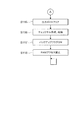
図5−1は、遊技制御部200による基本処理の動作を示すフローチャートである。
遊技制御部200は、パチンコ遊技機100の電源が投入されると、まず、RAM20
3(図3参照)へのアクセスを許可する(ステップ(以下、ステップを「S」と記載する
)101)。そして、遊技制御部200は、RAM203をクリアするためのRAMクリ
アスイッチがONとなっているか否かを判断する(S102)。
RAMクリアスイッチがOFFである場合(S102でNo)、次に、遊技制御部20
0は、電源遮断時の動作に関するバックアップフラグがONとなっているか否かを判断す
る(S103)。
バックアップフラグがONである場合(S103でYes)、次に、遊技制御部200
は、電源遮断時に作成されたチェックサムが正常か否かを判断する(S104)。
チェックサムが正常である場合(S104でYes)、次に、遊技制御部200は、復
帰処理を実行する(S105)。この復帰処理において、遊技制御部200は、電源が遮
断された状態からの復帰に伴う、演出制御部300等のサブ制御手段の設定を行う。具体
的には、遊技制御部200は、電源が遮断される際におけるパチンコ遊技機100の遊技
状態(大当たり遊技中か否か、高確率状態と低確率状態のいずれか、時短状態と時短無状
態のいずれか)を反映させるように、サブ制御手段を設定するためのコマンドを演出制御
部300へ出力する。また、この復帰処理において、遊技制御部200は、バックアップ
フラグをOFFにする。
FIG. 5A is a flowchart illustrating an operation of basic processing by the
When the power of the
3 (see FIG. 3) is permitted (step (hereinafter, step is referred to as “S”) 101). Then, the
When the RAM clear switch is OFF (No in S102), next, the game control unit 20
In 0, it is determined whether or not the backup flag relating to the operation at the time of power-off is ON (S103).
If the backup flag is ON (Yes in S103), then the
Determines whether the checksum created at the time of power-off is normal (S104).
If the checksum is normal (Yes in S104), the
一方、RAMクリアスイッチがON(S102でYes)、バックアップフラグがOF
F(S103でNo)、チェックサムが異常(S104でNo)のいずれかに該当する場
合、次に遊技制御部200は、初期化処理として、RAM203の記憶内容をクリアし(
S106)、RAM203の作業領域を設定する(S107)。そして、遊技制御部20
0は、サブ制御手段を設定(初期化)するためのコマンドを演出制御部300へ出力し、
サブ基板(サブ制御手段)の設定を行う(S108)。サブ基板の設定には、各サブ基板
に搭載されているRAM303、RAM313、RAM323をクリアすること等が含ま
れる。
On the other hand, the RAM clear switch is ON (Yes in S102) and the backup flag is OF
F (No in S103), if the checksum is abnormal (No in S104), the
S106), the work area of the
0 outputs a command for setting (initializing) the sub-control means to the
The sub board (sub control means) is set (S108). The setting of the sub board includes clearing the
復帰処理(S105参照)が終了した後、またはサブ基板の設定(S108参照)が終
了した後、遊技制御部200は、遊技制御に用いられる各種のカウンタおよびタイマーを
設定する(S109)。そして、遊技制御部200は、割り込み許可(S110)、割り
込み禁止(S111)、図柄乱数制御処理(S112)、初期値乱数更新処理(S113
)、電源遮断フラグがONとなっているか否かの判断(S114)をループ処理として繰
り返し実行する。
ここで、割り込み許可(S110)および割り込み禁止(S111)は、このループ処
理(S110〜S114)の実行中に割り込み処理の実行を可能とするために設けられて
いる。本実施の形態では、この割り込み処理により、遊技制御における主制御処理が実行
される。主制御処理の詳細については後述する。
図柄乱数制御処理(S112)において、遊技制御部200は、特別図柄抽選で用いら
れる変動パターン乱数の更新を行う。
初期値乱数更新処理(S113)において、遊技制御部200は、遊技制御において用
いられる各種の乱数値の初期値を更新する。
電源遮断フラグの判断において、電源遮断フラグがOFFである場合(S114でNo
)、パチンコ遊技機100の電源は遮断されず、遊技制御部200は、ループ処理(S1
10〜S114)と共に割り込みによる主制御処理を繰り返し実行する。一方、電源遮断
フラグがONである場合(S114でYes)、遊技制御部200は、パチンコ遊技機1
00の電源を遮断するための処理(電源遮断時処理)を開始する。
After the return process (see S105) is completed or after the setting of the sub-board (see S108) is finished, the
), It is repeatedly executed as a loop process to determine whether or not the power shutoff flag is ON (S114).
Here, interrupt permission (S110) and interrupt prohibition (S111) are provided to enable execution of interrupt processing during execution of the loop processing (S110 to S114). In the present embodiment, main control processing in game control is executed by this interrupt processing. Details of the main control process will be described later.
In the symbol random number control process (S112), the
In the initial value random number update process (S113), the
In the determination of the power shutdown flag, if the power shutdown flag is OFF (No in S114)
), The power of the
10 to S114) and repeatedly executes the main control process by interruption. On the other hand, when the power-off flag is ON (Yes in S114), the
The process for shutting off the power of 00 (process when power is shut off) is started.
図5−2は、遊技制御部200による電源遮断時処理の動作を示すフローチャートであ
る。
電源遮断時処理において、遊技制御部200は、まず、各種の出力を行うための出力ポ
ートの設定をクリアする(S115)。次に、遊技制御部200は、チェックサムを作成
し、RAM203に格納する(S116)。次に、遊技制御部200は、バックアップフ
ラグをONにし(S117)、RAM203へのアクセスを禁止して(S118)、無限
ループに移行する。
FIG. 5B is a flowchart illustrating the operation of power-off processing by the
In the power-off process, the
〔遊技機の主制御処理〕
次に、パチンコ遊技機100の主制御処理を説明する。
遊技制御部200は、主制御処理において、パチンコ遊技機100における遊技を制御
すると共に、サブ制御手段である演出制御部300に対して演出の制御を指示し、払出制
御部330に対して賞球の払い出しの制御を指示する。
[Main control processing of gaming machines]
Next, main control processing of the
In the main control process, the
図5−3は、遊技制御部200の主制御処理を示すフローチャートである。
主制御処理は、遊技制御における一連の処理からなり、予め設定された一定時間(例え
ば4ミリ秒)ごとに繰り返し実行される。本実施の形態において、遊技制御部200は、
予め設定された一定時間ごとに割り込みを発生させ、図5−1に示すループ処理の中で割
り込みが許可(S110参照)されると、割り込み処理として主制御処理を実行する。図
5−3に示すように、主制御処理では、乱数更新処理、スイッチ処理、図柄処理、電動役
物処理、賞球処理、出力処理が順次実行される(S501〜S506)。
FIG. 5-3 is a flowchart showing main control processing of the
The main control process includes a series of processes in game control, and is repeatedly executed at predetermined time intervals (for example, 4 milliseconds). In the present embodiment, the
When an interrupt is generated at predetermined time intervals and the interrupt is permitted in the loop process shown in FIG. 5A (see S110), the main control process is executed as the interrupt process. As shown in FIG. 5-3, in the main control process, a random number update process, a switch process, a symbol process, an electric accessory process, a prize ball process, and an output process are sequentially executed (S501 to S506).
乱数更新処理(S501)では、遊技制御部200は、乱数制御部241の機能(サブ
ルーチン)を呼び出し、遊技制御部200による遊技制御で用いられる各種の乱数の値を
更新する。乱数の設定および乱数値の更新の詳細については後述する。
In the random number update process (S501), the
スイッチ処理(S502)としては、始動口スイッチ処理、ゲートスイッチ処理が行わ
れる。
始動口スイッチ処理では、遊技制御部200は、乱数取得部231の機能(サブルーチ
ン)を呼び出し、図3の第1始動口スイッチ211および第2始動口スイッチ212の状
態を監視し、スイッチがONとなった場合に、特別図柄抽選のための処理を実行する。
ゲートスイッチ処理では、遊技制御部200は、普通図柄判定部232の機能(サブル
ーチン)を呼び出し、図3のゲートスイッチ214の状態を監視し、スイッチがONとな
った場合に、普通図柄抽選のための処理を実行する。
これらのスイッチ処理の詳細な内容については後述する。
As the switch process (S502), a start port switch process and a gate switch process are performed.
In the start port switch process, the
In the gate switch process, the
Details of these switch processes will be described later.
図柄処理(S503)としては、特別図柄処理、普通図柄処理が行われる。
特別図柄処理では、遊技制御部200は、特別図柄変動制御部233、特別図柄判定部
234、変動パターン選択部235の各機能(サブルーチン)を呼び出し、特別図柄変動
およびこの図柄変動に伴う処理を実行する。
普通図柄処理では、遊技制御部200は、普通図柄変動制御部236の機能(サブルー
チン)を呼び出し、普通図柄変動およびこの図柄変動に伴う処理を実行する。
これらの図柄処理の詳細な内容については後述する。
As the symbol processing (S503), special symbol processing and normal symbol processing are performed.
In the special symbol process, the
In the normal symbol process, the
The detailed contents of these symbol processes will be described later.
電動役物処理(S504)としては、大入賞口処理、電動チューリップ処理が行われる
。
大入賞口処理では、遊技制御部200は、大入賞口動作制御部237の機能(サブルー
チン)を呼び出し、所定の条件に基づいて大入賞口125の開放動作を制御する。
電動チューリップ処理では、遊技制御部200は、電動チューリップ動作制御部238
の機能(サブルーチン)を呼び出し、所定の条件に基づいて電動チューリップ123の開
放動作を制御する。
これらの電動役物処理の詳細な内容については後述する。
As the electric accessory process (S504), a big prize opening process and an electric tulip process are performed.
In the special prize opening process, the
In the electric tulip process, the
The function (subroutine) is called and the opening operation of the
The detailed contents of these electric accessory processing will be described later.
賞球処理(S505)では、遊技制御部200は、賞球処理部239の機能(サブルー
チン)を呼び出し、入賞個数の管理および入賞に応じた賞球の払い出しの制御用コマンド
をセットする。
In the prize ball processing (S505), the
出力処理(S506)では、遊技制御部200は、出力制御部240の機能(サブルー
チン)を呼び出し、演出制御用のコマンドを演出制御部300へ出力し、払い出し制御用
のコマンドを払出制御部330へ出力する。演出制御用コマンドは、S502からS50
4までの各処理において生成され、RAM203に設けられた制御用コマンドの格納領域
に格納(セット)される。払い出し制御用コマンドは、S505の処理において生成され
、RAM203に設けられた制御用コマンドの格納領域に格納(セット)される。RAM
203には、制御用コマンドの種類ごとに格納領域が設定されている。
In the output process (S506), the
4 is generated in each process up to 4, and is stored (set) in the storage area of the control command provided in the
In 203, a storage area is set for each type of control command.
出力制御部240は、RAM203の各制御用コマンドの格納領域を順に調べ、個々の
格納領域に制御用コマンドが格納されていれば(すなわち、S502〜S505の処理で
制御用コマンドが生成されていれば)、その制御用コマンドを読み出し、出力先(演出制
御部300または払出制御部330)へ出力する。
The
本実施の形態では、図5−3に示したように、一連の主制御処理の最後に出力処理を行
う。すなわち、第1の処理手段としての上記各機能によるS502〜S505の各処理に
おいて生成されたコマンドを、その各処理においてはRAM203の対応する格納領域に
格納しておく。そして、これらの処理の後に、第2の処理手段としての出力制御部240
が、RAM203の格納領域に蓄積された、各処理で生成されたコマンドをまとめて出力
する。言い換えれば、本実施の形態では、主制御処理を1サイクル実行すると、その1サ
イクルの実行において生成されたコマンドが、その1サイクルの実行における最後のコマ
ンド生成が行われた後に、出力される。
In the present embodiment, as shown in FIG. 5C, output processing is performed at the end of a series of main control processing. That is, the command generated in each process of S502 to S505 by the above functions as the first processing means is stored in a corresponding storage area of the
However, the commands generated in each process accumulated in the storage area of the
〔遊技機の基本動作の変形例〕
なお、図5−1乃至図5−3を参照して説明した動作例では、基本処理におけるループ
処理の部分で割り込みを許可し、割り込み処理として一連の処理からなる主制御処理を実
行した。しかしながら、主制御処理は、一定時間ごとに繰り返し実行されるように構成さ
れていれば良く、具体的な実現手段(実行手順)は、図5−1乃至図5−3に示した例に
は限定されない。例えば、基本処理の一連の動作の中に主制御処理を組み入れておき、所
定のタイミングで経過時間を計測し、一定時間(例えば4ミリ秒)ごとに主制御処理へ戻
る構成としても良い。また、基本処理の一連の動作の中に主制御処理を組み入れる一方で
、図5−1乃至図5−3を参照して説明した動作と同様に、一定時間ごとに割り込みを発
生させ、割り込みが発生したならば基本処理中に組み入れられた主制御処理へ戻る構成と
しても良い。
[Modified example of basic operation of gaming machine]
In the operation example described with reference to FIGS. 5A to 5C, the interrupt is permitted in the loop process portion of the basic process, and the main control process including a series of processes is executed as the interrupt process. However, the main control process only needs to be configured to be repeatedly executed at regular intervals, and specific implementation means (execution procedure) is not limited to the examples shown in FIGS. It is not limited. For example, the main control process may be incorporated in a series of operations of the basic process, the elapsed time may be measured at a predetermined timing, and the process may return to the main control process every certain time (for example, 4 milliseconds). In addition, while incorporating the main control process in the series of operations of the basic process, as in the operation described with reference to FIG. 5A to FIG. If it occurs, it may be configured to return to the main control process incorporated in the basic process.
また、基本処理で生成されたコマンドを出力する場合は、原則として、コマンドを生成
する度に、RAM203のコマンド格納領域に格納し、第2の処理手段である出力制御部
240の機能を呼び出して出力する。基本処理は、遊技の進行に関わる主制御処理とは異
なり、電源投入時にのみ行われる初期動作等の特別な処理である。また、基本処理は、電
源投入時のパチンコ遊技機100の状態等の条件に基づく分岐により処理手順が変動する
場合があるため、出力処理に漏れが無いように、生成したコマンドを速やかに出力する処
理である。なお、関連する複数の処理により連続的にコマンドが生成される場合等、具体
的な処理の要請に応じて、複数のコマンドをRAM203のコマンド格納領域に格納し、
まとめて出力する処理手順を採っても良い。
When a command generated by basic processing is output, in principle, every time a command is generated, the command is stored in the command storage area of the
You may take the process sequence output collectively.
〔遊技制御部での始動口スイッチ処理〕
図6は、図5−3のS502に示したスイッチ処理のうちの始動口スイッチ処理の内容
を示すフローチャートである。
この始動口スイッチ処理は、第1始動口121における入賞に対する処理と、第2始動
口122における入賞に対する処理とが順次行われる。図6を参照すると、遊技制御部2
00は、まず、第1始動口121に遊技球が入賞して第1始動口スイッチ211がONと
なったか否かを判断する(S601)。第1始動口スイッチ211がONとなったならば
、次に遊技制御部200は、第1始動口121の入賞における未変動分の保留数U1が上
限値未満か否かを判断する(S602)。図6に示す例では、上限値を4個としている。
保留数U1が上限値に達している場合は(S602でNo)、それ以上未変動分の入賞を
保留することができないので、第1始動口121における入賞に対する処理を終了する。
[Start-up switch processing in game control unit]
FIG. 6 is a flowchart showing the contents of the start port switch process in the switch process shown in S502 of FIG. 5-3.
In the start port switch process, a process for winning at the
In 00, first, it is determined whether or not a game ball is won at the
If the number of holds U1 has reached the upper limit (No in S602), it is not possible to hold any more unchanging winnings, so the process for winning at the
一方、保留数U1が上限値未満である場合(S602でYes)、遊技制御部200の
乱数取得部231は、今回の入賞による判定のための乱数値を取得し、RAM203に格
納する(S603)。ここでは、第1始動口121の入賞なので、特別図柄抽選のための
乱数値が取得される。このとき取得される乱数値は、S501の乱数更新処理で更新され
た値である。そして、この乱数値により、後の特別図柄処理において特別図柄抽選の結果
が確定される。ここにいう乱数値としては、大当たり、小当たりまたははずれを決定する
大当たり乱数値、大当たりの種類(大当たり遊技の終了後における時短状態か時短無状態
、高確率状態と低確率状態、長当たり、短当たり)を決定する図柄乱数値(大当たり図柄
乱数値)、図柄変動における変動パターンを特定するための変動パターン乱数値、はずれ
のときにリーチ有り演出をするか否かを決定するリーチ乱数値、等が含まれる。
そして、遊技制御部200は、保留数U1の値を1加算する(S604)。
On the other hand, when the hold number U1 is less than the upper limit value (Yes in S602), the random
Then, the
次に、遊技制御部200は、事前判定処理を行う(S605)。
ここで、事前判定処理とは、始動口における入賞により乱数の取得が既に行われている
が後述する特別図柄処理によって乱数の判定が未だ行われていない入賞球(保留球)につ
いて、特別図柄処理によって乱数が判定されるよりも以前にその乱数の判定を行う(事前
判定)処理である。
Next, the
Here, the pre-determination process is a special symbol process for a winning ball (holding ball) for which a random number has already been acquired by winning at the start opening, but has not yet been determined by a special symbol process described later. The random number is determined before the random number is determined by (preliminary determination).
そして、本実施の形態の演出制御部300は、後述するように、事前判定処理によって
判定された乱数の判定結果(事前判定結果)に基づいて、特別図柄処理によって乱数が判
定され、その判定結果(抽選結果)が報知されるよりも以前に、その判定結果を示唆する
予告演出を行うことができる。
事前判定に基づく予告演出として、例えば保留表示において行う例を挙げることができ
る。本実施の形態では、後述するように、始動口における入賞により乱数の取得が既に行
われているが、後述する特別図柄処理によって乱数の判定が未だ行われていない入賞球(
保留球)については画像表示部114において保留表示が行われる。そして、この保留表
示に事前判定結果を反映させ、その保留球に関して、その後に特別図柄処理による乱数の
判定が行われた際の判定結果を遊技者に示唆する。これによって、遊技者は、保留球に対
して期待を抱きながら遊技を行うことができる。
なお、事前判定結果を用いた予告演出は、保留表示に限らず、特別図柄処理による乱数
の判定結果(抽選結果)が報知されるよりも以前に行われる各種の演出内容に反映させる
ことで、多様な予告演出を行うことが可能になる。
And the production |
As a notice effect based on prior determination, for example, an example can be given in a hold display. In the present embodiment, as will be described later, a random number has already been acquired by winning at the start opening, but a winning ball that has not yet been determined by a special symbol process described later (
On the hold ball), hold display is performed in the
In addition, the notice effect using the pre-determined result is not limited to the hold display, but by reflecting it in various effect contents performed before the determination result (lottery result) of the random number by special symbol processing is notified, It becomes possible to perform various notice effects.
この後、遊技制御部200は、事前判定結果を演出制御部300に通知するために、S
605の事前判定処理による事前判定情報を含む事前判定結果コマンドをRAM203に
セットする(S606)。
さらに、遊技制御部200は、S604による保留数U1の増加を演出制御部300に
通知するための保留数増加コマンドをRAM203にセットし(S607)、第1始動口
121における入賞に対する処理を終了する。
Thereafter, the
A pre-determination result command including pre-determination information by the pre-determination process of 605 is set in the RAM 203 (S606).
Further, the
次に、第2始動口122における入賞に対する処理が行われる。図6を参照すると、次
に遊技制御部200は、第2始動口122に遊技球が入賞して第2始動口スイッチ212
がONとなったか否かを判断する(S608)。第2始動口スイッチ212がONとなっ
たならば、次に、遊技制御部200は、第2始動口122の入賞における未変動分の保留
数U2が上限値未満か否かを判断する(S609)。図6に示す例では、上限値を4個と
している。保留数U2が上限値に達している場合は(S609でNo)、それ以上未変動
分の入賞を保留することができないので、第2始動口122における入賞に対する処理を
終了する。
Next, a process for winning in the
It is determined whether or not is turned on (S608). If the second
一方、保留数U2が上限値未満である場合(S609でYes)、遊技制御部200の
乱数取得部231は、今回の入賞による抽選のための乱数値を取得し、RAM203に格
納する(S610)。ここでは、第2始動口122の入賞なので、上記のS603と同様
に、特別図柄抽選のための乱数値(大当たり乱数値、大当たり図柄乱数値)、リーチ乱数
値、変動パターン乱数値など)が取得される。このとき取得される乱数値は、S501の
乱数更新処理で更新された値である。そして、この乱数値により後の特別図柄処理におい
て特別図柄抽選の結果が確定される。
そして、遊技制御部200は、保留数U2の値を1加算する(S611)。
On the other hand, if the hold number U2 is less than the upper limit value (Yes in S609), the random
Then, the
次に、遊技制御部200は、事前判定処理を行う(S612)。この事前判定処理の内
容は、上記のS605と同様である。
この後、遊技制御部200は、事前判定結果を演出制御部300に通知するために、S
612の事前判定処理による事前判定情報を含む事前判定結果コマンドをRAM203に
セットする(S613)。
さらに、遊技制御部200は、S611による保留数U2の増加を演出制御部300に
通知するための保留数増加コマンドをRAM203にセットし(S614)、第2始動口
122における入賞に対する処理を終了する。
Next, the
Thereafter, the
A pre-determination result command including pre-determination information by the pre-determination process of 612 is set in the RAM 203 (S613).
Furthermore, the
〔遊技制御部でのゲートスイッチ処理〕
図7は、ゲート124を遊技球が通過した場合のゲートスイッチ処理の内容を示すフロ
ーチャートである。
このゲートスイッチ処理において、遊技制御部200は、まず、ゲート124を遊技球
が通過してゲートスイッチ214がONとなったか否かを判断する(S701)。ゲート
スイッチ214がONとなったならば、次に遊技制御部200は、未変動分の保留数Gが
上限値未満か否かを判断する(S702)。図7に示す例では、上限値を4個としている
。保留数Gが上限値に達している場合は(S702でNo)、それ以上未変動分の入賞を
保留することができないので、ゲートスイッチ処理を終了する。
[Gate switch processing in game control unit]
FIG. 7 is a flowchart showing the contents of the gate switch process when a game ball passes through the gate 124.
In this gate switch process, the
一方、保留数Gが上限値未満である場合(S702でYes)、遊技制御部200は、
遊技制御部200の乱数取得部231は、今回の入賞による抽選のための乱数値を取得し
、RAM203に格納する(S703)。ここでは、ゲート124の入賞なので、普通図
柄抽選のための乱数値(当たり乱数値など)が取得される。
On the other hand, when the number G of holding is less than the upper limit value (Yes in S702), the
The random
次に、遊技制御部200は、保留数Gの値を1加算する(S704)。
S704で保留数Gの値が加算された後、遊技制御部200は、S704による保留数
Gの増加を演出制御部300に通知するための保留数G増加コマンドをRAM203にセ
ットし(S705)、ゲート124における入賞に対する処理を終了する。
Next, the
After the value of the holding number G is added in S704, the
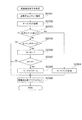
〔遊技制御部での特別図柄処理〕
図8は、図5−3のS503に示した図柄処理のうちの特別図柄処理の内容を示すフロ
ーチャートである。
この特別図柄処理において、遊技制御部200の特別図柄変動制御部233は、まず、
RAM203においてセットされるフラグの設定(以下、フラグ設定)において大当たり
遊技フラグがONになっているか否かを調べる(S801)。ここで、大当たり遊技フラ
グは、特別図柄抽選の結果が大当たりであることを識別するためにセットされるフラグで
ある。大当たりの種類に応じて、長当たり遊技フラグ、短当たり遊技フラグの何れかがセ
ットされる。本実施の形態では、これらを総称して大当たり遊技フラグと呼ぶ。
[Special symbol processing in game control unit]
FIG. 8 is a flowchart showing the contents of the special symbol processing in the symbol processing shown in S503 of FIG. 5-3.
In this special symbol processing, the special symbol
In the setting of the flag set in the RAM 203 (hereinafter referred to as flag setting), it is checked whether or not the jackpot game flag is ON (S801). Here, the jackpot game flag is a flag that is set to identify that the result of the special symbol lottery is a jackpot. Depending on the type of jackpot, either a long hit game flag or a short hit game flag is set. In the present embodiment, these are collectively referred to as a jackpot game flag.
大当たり遊技フラグがONである場合、既にパチンコ遊技機100は大当たり中である
ので、特別図柄変動を開始することなく特別図柄処理を終了する(S801でYes)。
一方、大当たり遊技フラグがOFFである場合(S801でNo)、次に特別図柄変動制
御部233は、パチンコ遊技機100の現在の状態が特別図柄変動中か否かを判断する(
S802)。特別図柄変動中でない場合(S802でNo)、次に特別図柄変動制御部2
33は、特別図柄の未変動分の保留数U1、U2(図6参照)に関する処理を行う(S8
03〜S806)。本実施の形態では、第1始動口121の入賞に係る保留数U1と第2
始動口122の入賞に係る保留数U2とを区別しているので、この処理も対応する始動口
ごとに個別に行う。
If the jackpot gaming flag is ON, the
On the other hand, when the jackpot game flag is OFF (No in S801), the special symbol
S802). If the special symbol is not changing (No in S802), then the special symbol
33 performs a process related to the number of holdings U1 and U2 (see FIG. 6) for the unchanging special symbol (S8).
03-S806). In the present embodiment, the holding number U1 and the second number related to winning of the
Since the number of holds U2 related to winning at the
具体的には、特別図柄変動制御部233は、まず第2始動口122の入賞に係る保留数
U2が1以上か判断する(S803)。保留数U2が1以上である場合(S803でYe
s)、特別図柄変動制御部233は、保留数U2の値を1減算する(S804)。一方、
保留数U2=0である場合は(S803でNo)、特別図柄変動制御部233は、次に第
1始動口121の入賞に係る保留数U1が1以上か判断する(S805)。保留数U1が
1以上である場合(S805でYes)、特別図柄変動制御部233は、保留数U1の値
を1減算する(S806)。一方、保留数U1=0である場合は(S805でNo)、特
別図柄の抽選を始動するための入賞が無いことを意味するため、特別図柄変動を開始せず
、別ルーチンの客待ち設定処理を実行して処理を終了する(S816)。
Specifically, the special symbol
s), the special symbol
When the number of holdings U2 = 0 (No in S803), the special symbol
S804またはS806で保留数U1または保留数U2を減算した後、特別図柄変動制
御部233は、RAM203のフラグ設定においてセットされた客待ちフラグをOFFと
する(S807)。客待ちフラグは、パチンコ遊技機100が客待ち状態であることを識
別するためのフラグであり、客待ち設定処理(S816、図12参照)においてセットさ
れる。
After subtracting the reserved number U1 or the reserved number U2 in S804 or S806, the special symbol
次に、特別図柄変動制御部233は、別ルーチンによる大当たり判定処理および変動パ
ターン選択処理を実行する(S808、S809)。詳しくは後述するが、この大当たり
判定処理および変動パターン選択処理によって、第1特別図柄表示器221に変動表示さ
れる特別図柄の変動用の設定情報(大当たり図柄、遊技状態、変動パターン等)が決定さ
れる。なお、これらの情報は演出制御部300に送られる変動開始コマンドに含まれる。
Next, the special symbol
この後、特別図柄変動制御部233は、大当たり判定処理および変動パターン選択処理
で決定された設定内容に基づき、図2に示す第1特別図柄表示器221、第2特別図柄表
示器222により表示される特別図柄の変動を開始する(S810)。そして、この設定
内容を示す設定情報(大当たり図柄、遊技状態、変動パターン等)を含んだ変動開始コマ
ンドを生成し、RAM203にセットする(S811)。S811でセットされた変動開
始コマンドは、図5−3のS506に示した出力処理で演出制御部300へ送信される。
Thereafter, the special symbol
S802で特別図柄変動中と判断された場合(S802でYes)、またはS811で
変動開始コマンドがセットされた後、特別図柄変動制御部233は、変動時間を経過した
か否かを判断する(S812)。すなわち、S810で特別図柄の変動を開始してからの
経過時間がS809の変動パターン選択処理で設定された変動時間に達したか否かが判断
される。変動時間を経過していなければ(S812でNo)、特別図柄変動が継続される
ので、そのまま特別図柄処理が終了する。
When it is determined in S802 that the special symbol is changing (Yes in S802), or after the change start command is set in S811, the special symbol
一方、変動時間を経過した場合(S812でYes)、特別図柄変動制御部233は、
まず、第1特別図柄表示器221、第2特別図柄表示器222における特別図柄の変動を
S808の大当たり判定処理で決定された図柄で停止する(S813)。後述する装飾図
柄を停止させるための変動停止コマンドをRAM203にセットする(S814)。そし
て、別ルーチンの停止中処理を実行する(S815)。停止中処理の内容については後述
する。S814でセットされた変動停止コマンドは、図5−3のS506に示した出力処
理で演出制御部300へ送信される。
On the other hand, when the variation time has elapsed (Yes in S812), the special symbol
First, the variation of the special symbols in the first
〔遊技制御部による大当たり判定処理〕
図9は、大当たり判定処理(図8のS808)の内容を示すフローチャートである。
この大当たり判定処理において、遊技制御部200の特別図柄判定部234は、まず、
今回の特別図柄抽選における大当たり乱数値の判定を行い(S901)、大当たりまたは
小当たりしたか否かを判断する(S902、S905)。大当たりまたは小当たりしたか
否かは、図6のS603またはS610で取得した大当たり乱数の値が、大当たりの当選
値として設定された値または小当たりの当選値として設定された値と一致したか否かを判
断することによって決定される(図17(a)参照)。
[Big hit judgment processing by game control unit]
FIG. 9 is a flowchart showing the contents of the jackpot determination process (S808 in FIG. 8).
In this jackpot determination process, the special
In this special symbol lottery, the jackpot random number is determined (S901), and it is determined whether the jackpot or the jackpot has been won (S902, S905). Whether or not the jackpot or the jackpot is determined is whether or not the value of the jackpot random number acquired in S603 or S610 of FIG. 6 matches the value set as the jackpot winning value or the value set as the jackpot winning value It is determined by judging whether or not (see FIG. 17A).
S901の乱数判定の結果が大当たりだった場合(S902でYes)、次に特別図柄
判定部234は、大当たり図柄乱数値の判定を行う(S903)。この判定の結果に応じ
て、大当たりの種類(高確率状態か低確率状態、時短状態か時短無状態、長当たり、短当
たり)が決定される。何れの大当たりとなるかは、図6のS603またはS610で取得
した大当たり図柄乱数の値が、大当たりの種類ごとに予め設定された値のうちの何れと一
致したかによって決定される(図17(b)参照)。
If the result of the random number determination in S901 is a big hit (Yes in S902), then the special
以上の判定の後、特別図柄判定部234は、大当たり図柄乱数の判定により決定された
大当たりの種類を表す図柄(大当たり図柄)を設定情報としてRAM203にセットする
(S904)。
After the above determination, the special
S901の乱数判定の結果が小当たりだった場合(S902でNo、S905でYes
)、次に特別図柄判定部234は、小当たりであることを表す図柄(以下、小当たり図柄
)を設定情報としてRAM203にセットする(S906)。
When the result of random number determination in S901 is a small hit (No in S902, Yes in S905)
Next, the special
S901の乱数判定の結果が大当たりでも小当たりでもない場合(S902、S905
でNo)、次に特別図柄判定部234は、抽選にはずれたことを表す図柄(以下、はずれ
図柄)を設定情報としてRAM203にセットする(S907)。
When the result of the random number determination in S901 is neither big win nor small win (S902, S905)
Next, the special
〔遊技制御部による変動パターン選択処理〕
図10は、変動パターン選択処理(図8のS809)の内容を示すフローチャートであ
る。
この変動パターン選択処理において、遊技制御部200の変動パターン選択部235は
、まず、パチンコ遊技機100の遊技状態(時短無状態か時短状態か、および高確率状態
か低確率状態か)を参照する(S1001)。そして、大当たり判定処理(図9)のS9
02の判断結果を用いて今回の特別図柄抽選で大当たりしたか否かを判断する(S100
2)。そして、大当たりだった場合(S1002でYes)、変動パターン選択部235
は、大当たり用の変動パターンテーブルをROM202から読み出してRAM203にセ
ットする(S1003)。
[Change pattern selection process by game control unit]
FIG. 10 is a flowchart showing the contents of the variation pattern selection process (S809 in FIG. 8).
In this variation pattern selection process, the variation
The judgment result of 02 is used to judge whether or not a big win has been won in this special symbol drawing (S100).
2). If it is a big hit (Yes in S1002), the variation
Reads the jackpot variation pattern table from the
一方、大当たりしなかった場合(S1002でNo)、次に変動パターン選択部235
は、遊技者に大当たりを期待させるためのいわゆるリーチ演出を行うか否かを決定するた
めの乱数値の判定を行う(S1004)。リーチ演出を行うか否かは、図6のS603ま
たはS610で取得したリーチ乱数の値が予め設定された値と一致したか否かを判断する
ことによって決定される(図17(c)参照)。
乱数値を用いた判定の結果、リーチ演出を行う場合(S1005でYes)、変動パタ
ーン選択部235は、リーチ用の変動パターンテーブルをROM202から読み出してR
AM203にセットする(S1006)。また、リーチ演出を行わない場合(S1005
でNo)、変動パターン選択部235は、はずれ用の変動パターンテーブルをROM20
2から読み出してRAM203にセットする(S1007)。
ここで、変動パターンテーブルとは、予め用意されている複数の変動パターン(変動時
間3秒、7秒、13秒、15秒、30秒、60秒、90秒など)と変動パターン乱数の値
とを対応付けたテーブルである。
On the other hand, if it is not a big hit (No in S1002), then the variation
Determines a random number value for determining whether or not to perform a so-called reach effect for making the player expect a big hit (S1004). Whether or not the reach effect is performed is determined by determining whether or not the reach random number value acquired in S603 or S610 in FIG. 6 matches a preset value (see FIG. 17C). .
As a result of the determination using the random number value, when the reach effect is performed (Yes in S1005), the variation
The
No), the variation
2 and set in the RAM 203 (S1007).
Here, the fluctuation pattern table includes a plurality of fluctuation patterns prepared in advance (
次に、変動パターン選択部235は、図6のS603またはS610で取得した変動パ
ターン乱数値およびS1003、S1006、S1007でセットされた変動パターンテ
ーブルを用いて、変動パターン乱数値の判定を行う(S1008)。すなわち、変動パタ
ーン選択部235は、RAM203にセットされた変動パターンテーブルを参照し、変動
パターン乱数の乱数値に応じた変動パターンを選択する。したがって、同じ乱数値が取得
された場合でも、パチンコ遊技機100の遊技状態(時短状態か時短無し状態か、および
高確率状態か低確率状態か)、特別図柄抽選の結果(大当たりしたか否か、大当たりして
いない場合はリーチ演出を行うか否か等、の違いに応じて参照される変動パターンテーブ
ルが異なるので、決定される変動パターンが異なる。
Next, the variation
この後、変動パターン選択部235は、S1008で選択した変動パターンを設定情報
としてRAM203にセットする(S1009)。S1009でセットされた変動パター
ンの設定情報は、図8のS811でセットされる変動開始コマンドに含まれ、図5−3の
S506に示した出力処理で演出制御部300へ送信される。本実施の形態で選択される
変動パターンおよびその設定の詳細については後述する。
Thereafter, the fluctuation
〔遊技制御部による停止中処理〕
図11は、停止中処理(図8のS815)の内容を示すフローチャートである。
この停止中処理において、遊技制御部200は、まず、RAM203のフラグ設定にお
いて時短状態であることを示すフラグ(以下、時短フラグ)がONになっているか否かを
調べる(S1101)。時短フラグがONである場合(S1101でYes)、遊技制御
部200は、時短状態での抽選回数(変動回数)Jの値を1減算し(S1102)、抽選
回数Jが0になったか否かを調べる(S1103)。そして、抽選回数J=0であれば(
S1103でYes)、時短フラグをOFFにする(S1104)。なお、時短フラグを
ONにする操作と、抽選回数Jの初期値の設定は、後述の大入賞口処理(図14)におけ
る遊技状態設定処理(図15)で行われる。
[Processing during stop by game control unit]
FIG. 11 is a flowchart showing the contents of the suspension process (S815 in FIG. 8).
In the stop process, the
If YES in S1103), the time reduction flag is turned OFF (S1104). It should be noted that the operation for turning on the hourly flag and the setting of the initial value of the lottery number J are performed in a game state setting process (FIG. 15) in a special winning opening process (FIG. 14) described later.
時短フラグがOFFであった場合(S1101でNo)またはS1104で時短フラグ
をOFFにした後、あるいは抽選回数Jの値が0でない場合(S1103でNo)、次に
遊技制御部200は、RAM203のフラグ設定において高確率状態であることを示すフ
ラグ(以下、確変フラグ)がONになっているか否かを調べる(S1105)。なお、こ
の確変フラグと先の時短フラグが共にONである場合は、高確率時短遊技状態であり、確
変フラグがONであり時短フラグがOFFである場合は、高確率時短無遊技状態である。
If the time reduction flag is OFF (No in S1101), or after the time reduction flag is turned OFF in S1104, or if the value of the lottery count J is not 0 (No in S1103), the
確変フラグがONである場合(S1105でYes)、遊技制御部200は、高確率状
態での抽選回数(変動回数)Xの値を1減算し(S1106)、抽選回数Xが0になった
か否かを調べる(S1107)。そして、抽選回数X=0であれば(S1107でYes
)、確変フラグをOFFにする(S1108)。なお、確変フラグをONにする操作と、
抽選回数Xの初期値の設定は、後述の大入賞口処理(図14)における遊技状態設定処理
(図15)で行われる。
When the probability variation flag is ON (Yes in S1105), the
), The probability variation flag is turned OFF (S1108). An operation to turn on the probability variation flag,
The initial value of the lottery number X is set in a game state setting process (FIG. 15) in a special prize opening process (FIG. 14) described later.
確変フラグがOFFであった場合(S1105でNo)またはS1108で確変フラグ
をOFFにした後、あるいは抽選回数Xの値が0でない場合(S1107でNo)、次に
遊技制御部200は、今回の特別図柄抽選で大当たりしたか否かを判断する(S1109
)。そして、大当たりだった場合(S1109でYes)、次に遊技制御部200は、大
当たりの種類が長当たりか否かを判断する(S1110)。
If the probability change flag is OFF (No in S1105), or after the probability change flag is turned OFF in S1108, or if the value of the lottery count X is not 0 (No in S1107), the
). If it is a big hit (Yes in S1109), the
ここで、大当たりか否かの判断は、大当たり判定処理(図9)の判定結果に基づいて判
断することができる。例えば、後述する図17(b)の図表に示す図柄の何れかがセット
されているならば、S1109でYesである。大当たり判定処理によりRAM203に
、はずれ図柄または小当たり図柄がセットされているならば、S1109でNoである。
Here, the determination of whether or not the jackpot is possible can be made based on the determination result of the jackpot determination process (FIG. 9). For example, if any of the symbols shown in the diagram of FIG. 17B to be described later is set, “Yes” is determined in S1109. If a lost symbol or a small bonus symbol is set in the
大当たりの種類が長当たりであった場合(S1110でYes)、遊技制御部200は
、長当たり遊技フラグをONにする(S1111)。これにより、RAM203の遊技状
態の設定が、大当たりの種類が長当たりである大当たり遊技状態(長当たり遊技状態)と
なる。なお、ここでは長当たりにおいて、高確率状態か低確率状態かを区別していない。
高確率状態となるか低確率状態となるかは、後述の大入賞口処理(図14)における遊技
状態設定処理(図15)で該当するフラグをONにすることによって特定される。
When the jackpot type is a long hit (Yes in S1110), the
Whether the state is a high probability state or a low probability state is specified by turning on a corresponding flag in a game state setting process (FIG. 15) in a special prize opening process (FIG. 14) described later.
大当たりの種類が長当たりでなかった場合(S1110でNo)、遊技制御部200は
、短当たり遊技フラグをONにする(S1112)。これにより、RAM203の遊技状
態の設定が、大当たりの種類が短当たりである大当たり遊技状態(短当たり遊技状態)と
なる。長当たりの場合と同様、短当たりの場合も高確率状態か低確率状態かを区別してい
ない。
If the jackpot type is not long hit (No in S1110), the
S1111またはS1112で大当たり遊技フラグをONにした後、遊技制御部200
は、抽選回数J、Xの値を初期化する(S1113)。また、遊技制御部200は、S1
101において時短フラグがONであって、S1103において抽選回数Jが0でなかっ
た場合に、時短フラグをOFFにする(S1114)。同様に、S1105において確変
フラグがONであって、S1107において抽選回数Xが0でなかった場合に、確変フラ
グをOFFにする(S1114)。
After turning on the jackpot game flag in S1111 or S1112, the
Initializes the values of the lottery times J and X (S1113). In addition, the
If the time flag is ON in 101 and the lottery count J is not 0 in S1103, the time flag is turned OFF (S1114). Similarly, when the probability variation flag is ON in S1105 and the number of lotteries X is not 0 in S1107, the probability variation flag is turned OFF (S1114).
一方、今回の特別図柄抽選の結果が大当たりでなかった場合(S1109でNo)、次
に遊技制御部200は、今回の特別図柄抽選の結果が小当たりであったか否かを判断する
(S1115)。小当たりでなかった場合は(S1115でNo)、停止中処理を終了す
る。
一方、小当たりであった場合(S1115でYes)、遊技制御部200は、小当たり
遊技を開始する(S1116)。これにより、RAM203の遊技状態の設定が小当たり
遊技状態となる。なお、小当たり遊技では、前述したように、大入賞口125を所定回数
開閉し、所定時間経過後に終了する。
On the other hand, when the result of the special symbol lottery this time is not a big hit (No in S1109), the
On the other hand, when it is a small hit (Yes in S1115), the
S1113で抽選回数J、Xの値を初期化した後、遊技制御部200は、オープニング
動作を開始する(S1117)。ここで、オープニング動作の内容は、S1111、S1
112の何れで当たり遊技フラグがONとなったかに応じて異なる。すなわち、大当たり
遊技フラグの状態に応じて、長当たり遊技、短当たり遊技の各遊技状態において設定され
たオープニング動作の何れかが行われることとなる。
この後、遊技制御部200は、演出制御部300において大当たり遊技フラグに応じた
オープニング動作における演出を行うためのオープニングコマンドをRAM203にセッ
トして(S1118)、停止中処理を終了する。このオープニングコマンドは、図5−3
のS506に示した出力処理で演出制御部300へ送信される。
After initializing the values of the lottery times J and X in S1113, the
It differs depending on which of 112 is the winning game flag turned ON. In other words, depending on the state of the big hit game flag, one of the opening operations set in each of the long win games and the short win game state is performed.
Thereafter, the
Is transmitted to the
〔遊技制御部による客待ち設定処理〕
図12は、客待ち設定処理(図8のS816)の内容を示すフローチャートである。
この客待ち設定処理において、遊技制御部200は、まず、RAM203のフラグ設定
において客待ちフラグがONになっているか否かを調べる(S1201)。ここで、客待
ちフラグは、パチンコ遊技機100が客待ち状態であることを識別するためにセットされ
るフラグである。
[Customer waiting setting process by game control unit]
FIG. 12 is a flowchart showing the contents of the customer waiting setting process (S816 in FIG. 8).
In this customer waiting setting process, the
客待ちフラグがONである場合、パチンコ遊技機100は客待ち状態であるので、その
まま処理を終了する(S1201でYes)。一方、客待ちフラグがOFFである場合、
遊技制御部200は、客待ちコマンドを生成してRAM203にセットし(S1202)
、客待ちフラグをONにする(S1203)。S1202でセットされた客待ちコマンド
は、図5−3のS506に示した出力処理で演出制御部300へ送信される。なお、客待
ちフラグとは、特別図柄の変動が停止して、保留が無い状態でセットされるものである。
If the customer waiting flag is ON, the
The
The customer waiting flag is turned ON (S1203). The customer waiting command set in S1202 is transmitted to the
〔遊技制御部による普通図柄処理〕
図13は、図5−3のS503に示した図柄処理のうちの普通図柄処理の内容を示すフ
ローチャートである。
この普通図柄処理において、遊技制御部200の普通図柄変動制御部236は、まず、
RAM203のフラグ設定において補助遊技フラグがONになっているか否かを調べる(
S1301)。ここで、補助遊技フラグは、普通図柄抽選で当選した場合にセットされる
フラグである。補助遊技フラグが設定されている状態は、電動チューリップ123が後述
の電動チューリップ処理(図16)にしたがって開放され、第2始動口122に入賞し易
い状態である(補助遊技状態)。
[Normal symbol processing by game control unit]
FIG. 13 is a flowchart showing the contents of the normal symbol processing in the symbol processing shown in S503 of FIG. 5-3.
In this normal symbol processing, the normal symbol
It is checked whether or not the auxiliary game flag is ON in the flag setting of the RAM 203 (
S1301). Here, the auxiliary game flag is a flag that is set when a normal symbol lottery is won. The state in which the auxiliary game flag is set is a state in which the
補助遊技フラグがONである場合、既に補助遊技状態となっており、普通図柄が停止し
ている状態なので、普通図柄変動を開始することなく普通図柄処理を終了する(S130
1でYes)。一方、補助遊技フラグがOFFである場合(S1301でNo)、次に普
通図柄変動制御部236は、パチンコ遊技機100の現在の状態が普通図柄変動中か否か
を判断する(S1302)。普通図柄変動中でない場合(S1302でNo)、次に普通
図柄変動制御部236は、普通図柄の未変動分の保留数G(図7参照)が1以上か判断す
る(S1303)。保留数G=0である場合は(S1303でNo)、普通図柄の抽選を
始動するための入賞が無いことを意味するため、普通図柄変動を開始せずに処理を終了す
る。
When the auxiliary game flag is ON, since the auxiliary game state has already been reached and the normal symbol is stopped, the normal symbol processing is terminated without starting the normal symbol variation (S130).
1 is Yes). On the other hand, if the auxiliary game flag is OFF (No in S1301), then the normal symbol
これに対し、保留数Gが1以上である場合(S1303でYes)、普通図柄変動制御
部236は、保留数Gの値を1減算し(S1304)、今回の普通図柄抽選における当た
り乱数の判定を行って、普通図柄抽選に当選したか否かを判断する(S1305)。当選
したか否かは、図7のS703で取得した当たり乱数の値が、後述する図17(d)に示
すテーブル等において当選値として設定された値と一致したか否かを判断することによっ
て決定される。
On the other hand, when the reserved number G is 1 or more (Yes in S1303), the normal symbol
次に、普通図柄変動制御部236は、普通図柄抽選の結果に応じて普通図柄の設定を行
う(S1306)。すなわち、普通図柄抽選に当選した場合は、当選したことを表す図柄
(以下、当たり図柄)を設定情報としてRAM203にセットする。一方、普通図柄抽選
に当選しなかった場合は、抽選にはずれたことを表す図柄(以下、はずれ図柄)を設定情
報としてRAM203にセットする。
Next, the normal symbol
次に、普通図柄変動制御部236は、普通図柄の変動時間の設定を行う(S1307)
。この変動時間は、図11におけるS1104、S1114、後述の図15におけるS1
504、S1507等の処理で設定される時短フラグに基づいて設定される。すなわち、
S1307による設定の際に時短フラグがONである場合は、短時間(例えば1.5秒)
に設定され、時短フラグがOFFである場合は、長時間(例えば4.0秒)に設定される
。この設定の後、普通図柄変動制御部236は、S1307の設定内容に基づき、図2(
a)および図3に示す普通図柄表示器223における普通図柄の変動を開始する(S13
08)。
Next, the normal symbol
. This variation time is determined by S1104 and S1114 in FIG. 11 and S1 in FIG.
504, S1507, etc. are set based on the time reduction flag set in the process. That is,
If the hour / short flag is ON at the time of setting in S1307, a short time (eg, 1.5 seconds)
When the time reduction flag is OFF, it is set to a long time (for example, 4.0 seconds). After this setting, the normal symbol
The normal symbol change in the
08).
S1308で普通図柄の変動を開始した後、またはS1302で普通図柄変動中と判断
された場合(S1302でYes)、普通図柄変動制御部236は、変動時間を経過した
か否かを判断する(S1309)。すなわち、S1308で普通図柄の変動を開始してか
らの経過時間がS1307で設定された変動時間に達したか否かが判断される。変動時間
を経過していなければ(S1309でNo)、普通図柄変動が継続されるので、そのまま
普通図柄処理が終了する。
After starting the change of the normal symbol in S1308 or when it is determined that the normal symbol is changing in S1302 (Yes in S1302), the normal symbol
一方、変動時間が終了した場合(S1309でYes)、普通図柄変動制御部236は
、普通図柄表示器223における普通図柄の変動を停止する(S1310)。そして、普
通図柄変動制御部236は、停止した普通図柄に基づき普通図柄抽選に当選したか否かを
判断する(S1311)。当選したならば(S1311でYes)、補助遊技フラグをO
Nにする(S1312)。一方、抽選にはずれたならば(S1311でNo)、補助遊技
フラグをONにすること無く普通図柄処理を終了する。
On the other hand, when the fluctuation time is over (Yes in S1309), the normal symbol
N (S1312). On the other hand, if the lottery is off (No in S1311), the normal symbol processing is terminated without turning on the auxiliary game flag.
〔遊技制御部による大入賞口処理〕
図14は、図5−3のS504に示した電動役物処理のうちの大入賞口処理の内容を示
すフローチャートである。
この大入賞口処理において、遊技制御部200の大入賞口動作制御部237は、まず、
RAM203のフラグ設定において大当たり遊技フラグがONになっているか否かを調べ
る(S1401)。大当たり遊技フラグがOFFである場合、大入賞口125への入賞は
ないので、大入賞口処理を終了する(S1401でNo)。一方、大当たり遊技フラグが
ONである場合(S1401でYes)、次に大入賞口動作制御部237は、パチンコ遊
技機100が停止中処理(図11)で開始された大当たり時の動作制御におけるオープニ
ング動作の最中か否かを判断する(S1402)。
[Large winning mouth processing by game control unit]
FIG. 14 is a flowchart showing the contents of the big prize opening process in the electric accessory process shown in S504 of FIG. 5-3.
In this special winning opening process, the special winning opening
It is checked whether or not the jackpot game flag is ON in the flag setting of the RAM 203 (S1401). When the big hit game flag is OFF, there is no winning in the big winning
パチンコ遊技機100がオープニング中である場合(S1402でYes)、次に大入
賞口動作制御部237は、予め設定されたオープニング動作が行われるべき時間(オープ
ニング時間)を経過したか否かを判断する(S1403)。オープニング時間を経過して
いないならば、大入賞口125でのオープニング動作が継続されるので、大入賞口処理を
終了する(S1403でNo)。一方、オープニング時間を経過したならば(S1403
でYes)、次に大入賞口動作制御部237は、大入賞口125の作動設定を行い(S1
404)、入賞個数Cを初期化(C=0)し(S1405)、大入賞口125の作動のラ
ウンド数Rの値を現在の値から1加算して(S1406)、大入賞口125を作動開始(
開放)する(S1407)。
When the
Next, the special prize opening
404), the winning number C is initialized (C = 0) (S1405), and the value of the number R of rounds of operation of the
Open) (S1407).
S1404の作動設定では、大入賞口125の作動パターンと、その作動パターンで作
動させるラウンド数(作動ラウンド数)とが設定される。大入賞口125が作動する場合
としては、特別図柄抽選で、長当たりまたは短当たりの大当たりであった場合と、小当た
りであった場合がある。作動パターンおよびラウンド数は、これらの当たりの種類に応じ
て様々に設定される。一例としては、長当たりの場合、例えば、15ラウンド(15R)
作動させ、1ラウンドでは29.5秒の開放を1回行う。短当たりの場合、例えば、15
ラウンド(15R)作動させ、1ラウンドでは0.1秒の開放を1回行う。小当たりの場
合、例えば、1ラウンド(1R)作動させ、この1ラウンドで0.1秒の開放を15回行
う。ここで、短当たりでの作動と小当たりでの作動を上記の例で比較すると、共に0.1
秒の開放が15回行われることとなる。すなわち、遊技者から見える大入賞口125の動
作は、短当たりの場合と小当たりの場合とで同じであり、遊技盤110上の大入賞口12
5の動作のみから短当たりと小当たりとを区別することはできない。
In the operation setting of S1404, the operation pattern of the special winning
Operate and open once for 29.5 seconds per round. For example, 15
The round (15R) is activated, and one round is opened once for 0.1 seconds. In the case of a small hit, for example, one round (1R) is operated, and 0.1 second is released 15 times in this round. Here, when the operation with short hits and the operation with small hits are compared in the above example, both are 0.1%.
The seconds are released 15 times. That is, the action of the
It is not possible to distinguish between short hits and small hits only from the operation of 5.
また、別の例としては、長当たりでは、15ラウンド(15R)作動させ、1ラウンド
では29.5秒の開放を1回行い、短当たりでは、2ラウンド(2R)作動させ、1ラウ
ンドでは0.9秒の開放を2回行い、小当たりでは、1ラウンド(1R)作動させ、この
1ラウンドで0.9秒の開放を2回行う。この場合も、短当たりでの作動と小当たりでの
作動を比較すると、共に0.9秒の開放が2回行われることとなり、遊技者から見える大
入賞口125の動作は、短当たりの場合と小当たりの場合とで同様となる。
As another example, 15 rounds (15R) are activated per long, 29.5 seconds are released once per round, 2 rounds (2R) are activated per short, and 0 are rounded per round. .9 seconds are opened twice, and with a small hit, one round (1R) is operated, and 0.9 seconds is opened twice in this round. In this case as well, when the operation with short hits and the operation with small hits are compared, both 0.9 seconds are released twice, and the action of the
なお、小当たりの際には、大入賞口125の開放累積時間が1.8秒以内に設定されな
ければならないことが法令により定められている。一方で、大当たり(長当たりまたは短
当たり)の際には、大入賞口125を複数回連続開放させなければならない。そこで、上
記のように小当たりでの作動と短当たりでの作動を外見上区別し難くしようとする場合、
小当たりでは、1作動での開放累積時間が1.8秒以内を満たす範囲で、大入賞口125
が2回以上開放する作動形態が設定され、短当たりでは、小当たりの開放回数と同数のラ
ウンド数が設定される。
The law stipulates that the cumulative opening time of the special winning
For small wins, the winning prize opening 125 is within the range that the accumulated opening time in one operation is within 1.8 seconds.
Is set to open twice or more, and in the short win, the same number of rounds as the number of small hits is set.
次に、大入賞口動作制御部237は、S1404で設定された作動パターンにおける開
放時間を経過したか否かを判断する(S1408)。大入賞口125での開放状態が開放
時間を経過していない場合(S1408でNo)、次に大入賞口動作制御部237は、大
入賞口125への入賞個数Cが規定の個数(例えば9個)以上か否かを判断する(S14
09)。開放時間を経過しておらず、かつ入賞個数Cが規定個数未満である場合は、大入
賞口125の作動状態(開放状態)が継続されるので、大入賞口処理を終了する(S14
09でNo)。一方、開放時間を経過したか(S1408でYes)、または入賞個数C
が規定個数に達した場合(S1409でYes)、大入賞口動作制御部237は、大入賞
口125を作動終了(閉口)する(S1410)。
Next, the special prize opening
09). If the opening time has not elapsed and the number C of winning prizes is less than the specified number, the operating state (open state) of the big winning
09, No). On the other hand, whether the opening time has elapsed (Yes in S1408), or the number of winning prizes C
When the predetermined number is reached (Yes in S1409), the special prize opening
次に、大入賞口動作制御部237は、大入賞口125の作動のラウンド数RがS140
4で設定された最大値に達したか否かを判断する(S1411)。そして、最大値に達し
ていないならば、残りの作動が行われるため、大入賞口処理を終了する(S1411でN
o)。
Next, the prize winning opening
It is determined whether or not the maximum value set in 4 has been reached (S1411). If the maximum value has not been reached, the remaining operations are performed, so that the big prize opening process is terminated (N in S1411).
o).
大入賞口125の作動のラウンド数Rが最大値に達したならば(S1411でYes)
、次に大入賞口動作制御部237は、エンディング動作を開始する(S1412)。ここ
で、エンディング動作の内容は、長当たり遊技、短当たり遊技の各遊技状態において設定
されたエンディング動作のうち、大当たり遊技フラグの状態に対応するものとなる。
この後、大入賞口動作制御部237は、演出制御部300において大当たり遊技フラグ
に応じたエンディング動作における演出を行うためのエンディングコマンドをRAM20
3にセットする(S1413)。このエンディングコマンドは、図5−3のS506に示
した出力処理で演出制御部300へ送信される。
If the number R of rounds of operation of the
Next, the special winning opening
Thereafter, the special winning opening
3 is set (S1413). This ending command is transmitted to the
次に、大入賞口動作制御部237は、大入賞口125の作動のラウンド数Rを0にリセ
ットした後(S1414)、エンディング動作の開始からの経過時間が予め設定されたエ
ンディング動作が行われるべき時間(エンディング時間)を経過したか否かを判断する(
S1417)。エンディング時間を経過していないならば、エンディング動作が継続され
るので、大入賞口処理を終了する(S1417でNo)。一方、エンディング時間を経過
したならば(S1417でYes)、次に大入賞口動作制御部237は、遊技制御部20
0による遊技状態設定処理を経た後(S1418)、大当たり遊技フラグをOFFにして
、大入賞口処理を終了する(S1419)。遊技状態設定処理の内容については後述する
。
Next, the special winning opening
S1417). If the ending time has not elapsed, the ending operation is continued, and thus the big prize opening process is terminated (No in S1417). On the other hand, if the ending time has elapsed (Yes in S1417), the special winning opening
After the game state setting process of 0 (S1418), the big hit game flag is turned OFF and the big winning opening process is ended (S1419). The contents of the game state setting process will be described later.
S1402で、パチンコ遊技機100がオープニング中ではないと判断した場合(S1
402でNo)、次に大入賞口動作制御部237は、エンディング中か否かを判断する(
S1415)。そして、エンディング中であるならば(S1415でYes)、上記S1
417以降の動作を実行する。
When it is determined in S1402 that the
Next, the special winning opening
S1415). If it is ending (Yes in S1415), the above S1
The operation after 417 is executed.
一方、パチンコ遊技機100がエンディング中でもないならば(S1415でNo)、
次に大入賞口動作制御部237は、大入賞口125が作動(開放)中か否かを判断する(
S1416)。そして、作動中でないならば(S1416でNo)、上記S1405以降
の動作を実行し、作動中であるならば(S1416でYes)、上記S1408以降の動
作を実行する。
なお、前述した小当たり遊技で行われる演出は、短当たり遊技で行われる演出と同様で
あり、演出から短当たりと小当たりとを区別することはできない。
On the other hand, if the
Next, the special prize opening
S1416). If it is not in operation (No in S1416), the operation after S1405 is executed. If it is in operation (Yes in S1416), the operation after S1408 is executed.
The effect performed in the small hit game described above is the same as the effect performed in the short hit game, and it is not possible to distinguish short hit and small hit from the effect.
〔遊技状態設定処理〕
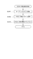
エンディング時間が経過した場合(S1417でYes)に実行される、遊技制御部2
00による遊技状態設定処理(S1418)の内容を図15に示す。
遊技状態設定処理が行われる場合、前提として、図14のS1401で大当たり遊技フ
ラグがONとなっている。そこで、図15に示すように、遊技制御部200は、まず、そ
の大当たりの種類を判断する(S1501、S1502、S1503、S1506)。こ
れらの判断は、例えば大当たり判定処理(図9)でRAM203に設定情報としてセット
された図柄の種類に基づいて判断することができる。なお、これらの判断は大当たり判定
処理(図9)のS902、S903、S905と概ね同様であるので、S902、S90
3、S905の判断結果を用いても良い。
[Game state setting process]
The
FIG. 15 shows the contents of the game state setting process (S1418) based on 00.
When the game state setting process is performed, the jackpot game flag is set to ON in S1401 of FIG. Therefore, as shown in FIG. 15, the
3. The determination result of S905 may be used.
小当たりである場合(S1501でYes)、遊技状態は変更しないので、遊技状態設
定処理を終了する。
大当たりの種類が低確率時短遊技状態の大当たりである場合(S1501でNo、S1
502、S1503でYes)、遊技制御部200は、時短フラグをONにする(S15
04)。これにより、RAM203の遊技状態の設定が低確率時短遊技状態となる。また
、遊技制御部200は、抽選回数Jの初期値を設定し(S1505)、遊技状態設定処理
を終了する。抽選回数Jの初期値は、図示の例では100回である。したがって、低確率
時短遊技状態における抽選が100回行われたならば、低確率時短遊技状態が終了し、低
確率時短無遊技状態となる。
If it is a small hit (Yes in S1501), the gaming state is not changed, so the gaming state setting process is terminated.
When the type of jackpot is a jackpot of the low-probability short game state (No in S1501, S1
502, Yes in S1503), the
04). Thereby, the setting of the gaming state in the
一方、大当たりの種類が低確率時短無遊技状態の大当たりである場合(S1501でN
o、1502でYes、S1503でNo)、遊技制御部200は、時短フラグ、確変フ
ラグともONにせずに処理を終了する。したがって、この大当たりの後の遊技に対するR
AM203の遊技状態の設定は、低確率時短無遊技状態となる。
On the other hand, when the type of jackpot is a jackpot of a low probability short-time no-game state (N in S1501)
o, Yes in 1502, No in S1503), the
The game state setting of
大当たりの種類が高確率時短遊技状態の大当たりである場合(S1501、S1502
でNo、S1506でYes)、遊技制御部200は、時短フラグをONにし(S150
7)、抽選回数Jの初期値を設定する(S1508)。この場合の抽選回数Jの初期値は
、図示の例では10000回である。また、遊技制御部200は、確変フラグをONにし
(S1509)、抽選回数Xの初期値を設定する(S1510)。抽選回数Xの初期値は
、図示の例では10000回である。これにより、RAM203の遊技状態の設定が高確
率時短遊技状態となる。そして、この高確率時短遊技状態における抽選が10000回行
われたならば、高確率時短遊技状態が終了し、低確率時短無遊技状態となる。
When the type of jackpot is a jackpot of a high probability short game state (S1501, S1502)
No, in S1506, Yes), the
7) The initial value of the lottery number J is set (S1508). In this case, the initial value of the number of times of lottery J is 10,000 in the illustrated example. Further, the
一方、大当たりの種類が高確率時短無遊技状態の大当たりである場合(S1501、S
1502、S1506でNo)、遊技制御部200は、確変フラグのみをONにし(S1
509)、抽選回数Xの初期値(10000回)を設定する(S1510)。これにより
、RAM203の遊技状態の設定が高確率時短無遊技状態となる。そして、この高確率時
短無遊技状態における抽選が10000回行われたならば、高確率時短無遊技状態が終了
し、低確率時短無遊技状態となる。
On the other hand, when the type of jackpot is a jackpot of a high probability short-time no-game state (S1501, S
1502, No in S1506), the
509), an initial value (10000 times) of the lottery number X is set (S1510). Thereby, the setting of the gaming state in the
〔遊技制御部による電動チューリップ処理〕
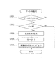
図16は、図5−3のS504に示した電動役物処理のうちの電動チューリップ処理の
内容を示すフローチャートである。
電動チューリップ処理において、遊技制御部200の電動チューリップ動作制御部23
8は、まず、RAM203のフラグ設定において補助遊技フラグがONになっているか否
かを調べる(S1601)。補助遊技フラグがOFFである場合、電動チューリップ12
3は開放しないため、電動チューリップ処理を終了する(S1601でNo)。一方、補
助遊技フラグがONである場合(S1601でYes)、次に電動チューリップ動作制御
部238は、電動チューリップ123が作動中か否かを判断する(S1602)。
[Electric tulip processing by game control unit]
FIG. 16 is a flowchart showing the contents of the electric tulip process in the electric accessory process shown in S504 of FIG. 5-3.
In the electric tulip process, the electric tulip operation control unit 23 of the
8. First, it is checked whether or not the auxiliary game flag is ON in the flag setting of the RAM 203 (S1601). When the auxiliary game flag is OFF, the electric tulip 12
Since 3 does not open, the electric tulip process is terminated (No in S1601). On the other hand, if the auxiliary game flag is ON (Yes in S1601), the electric tulip
電動チューリップ123が作動中でない場合(S1602でNo)、電動チューリップ
動作制御部238は、電動チューリップ123の作動パターンの設定を行い(S1603
)、設定した作動パターンで電動チューリップ123を作動させる(S1604)。ここ
で、作動パターンは、図11におけるS1104、S1114、図15におけるS150
4、S1507等の処理で設定される時短フラグに基づいて設定される。例えば、S16
03による設定の際に時短フラグがOFFである場合は、0.15秒の開放時間で1回開
放する作動パターンが設定され、時短フラグがONである場合は、1.80秒の開放時間
で3回開放する作動パターンが設定される。このように、通常、時短フラグがONである
とき(時短状態のとき)は、電動チューリップ123が長時間、複数回開放され、第2始
動口122に入賞し易くなる入賞サポート(電チューサポート)が行われる。
If the
) The
4. Set based on the time reduction flag set in the processing such as S1507. For example, S16
When the time reduction flag is OFF when setting by 03, an operation pattern is set to open once with an opening time of 0.15 seconds, and when the time reduction flag is ON, an opening time of 1.80 seconds is set. An operating pattern that opens three times is set. Thus, normally, when the time reduction flag is ON (when it is in the time reduction state), the
S1602で電動チューリップ123が作動中と判断された場合(S1602でYes
)、またはS1604で電動チューリップ123を作動させた後、電動チューリップ動作
制御部238は、設定されている作動パターンにおける開放時間が経過したか否かを判断
する(S1605)。開放時間を経過していなければ、電動チューリップ123の作動状
態(開放状態)が継続されるので、電動チューリップ処理を終了する(S1605でNo
)。一方、開放時間を経過したならば(S1605でYes)、電動チューリップ動作制
御部238は、補助遊技フラグをOFFとして、電動チューリップ処理を終了する(S1
606)。
When it is determined in S1602 that the
) Or after operating the
). On the other hand, if the opening time has elapsed (Yes in S1605), the electric tulip
606).
〔乱数による判定の手法〕
ここで、大当たり判定処理(図9)、変動パターン選択処理(図10)、普通図柄処理
(図13)等で行われる、乱数による判定の手法について詳細に説明する。
図17は、本実施の形態において特別図柄抽選および普通図柄抽選で用いられる乱数(
判定テーブル)の構成例を示す図である。
図17(a)には特別図柄抽選で用いられる大当たり乱数の構成例、図17(b)には
特別図柄抽選で用いられる大当たり図柄乱数の構成例、図17(c)には特別図柄抽選で
用いられるリーチ乱数の構成例、図17(d)には普通図柄抽選で用いられる当たり乱数
の構成例が、それぞれ示されている。
[Random number judgment method]
Here, a determination method using random numbers performed in the jackpot determination process (FIG. 9), the variation pattern selection process (FIG. 10), the normal symbol process (FIG. 13), and the like will be described in detail.
FIG. 17 shows a random number used in the special symbol lottery and the normal symbol lottery in this embodiment (
It is a figure which shows the structural example of a determination table.
FIG. 17A shows a configuration example of a jackpot random number used in the special symbol lottery, FIG. 17B shows a configuration example of the jackpot random number used in the special symbol lottery, and FIG. 17C shows a special symbol lottery. A configuration example of reach random numbers used, and FIG. 17 (d) each show a configuration example of hit random numbers used in normal symbol lottery.
図17(a)を参照すると、大当たり乱数の判定値として、大当たり判定時のパチンコ
遊技機100の遊技状態が低確率状態の場合の大当たりと大当たり判定時の遊技状態が高
確率状態の場合の大当たりの2種類と、小当たりとが設定されている。乱数(大当たり乱
数)の値の範囲は、何れも0〜299の300個である。低確率状態の特別図柄抽選(大
当たり抽選)の場合、当選値は1つだけが設定され、当選確率は1/300である。また
高確率状態の特別図柄抽選の場合、当選値は10個設定され、当選確率は10/300(
=1/30)である。すなわち図示の例では、高確率状態で始動口121、122に入賞
し特別図柄抽選が行われると、低確率状態で特別図柄抽選が行われる場合に比べて、当選
確率が10倍となる。また、小当たりの当選値は、低確率状態か高確率状態かに関わらず
3個設定され、当選確率は3/300(=1/100)である。
Referring to FIG. 17 (a), as the jackpot random number determination value, the jackpot when the gaming state of the
= 1/30). That is, in the example shown in the figure, if the winning
図17(b)を参照すると、大当たり図柄には、低確率図柄A、低確率図柄B、高確率
図柄A、高確率図柄B、潜確図柄の5種類が用意されている。ここで、低確率図柄Aおよ
び低確率図柄Bは、低確率状態の大当たりであることを表す図柄であり、このうち低確率
図柄Aは長当たり(低確率時短遊技状態)、低確率図柄Bは短当たり(低確率時短無遊技
状態)をそれぞれ表す。高確率図柄Aおよび高確率図柄Bは、高確率状態の大当たりであ
ることを表す図柄であり、このうち高確率図柄Aは長当たり(高確率時短遊技状態)、高
確率図柄Bは短当たり(高確率時短無遊技状態)をそれぞれ表す。潜確図柄は、高確率時
短無遊技状態の大当たりであることを表す図柄である。したがって、高確率図柄Bと潜確
図柄とは大当たり遊技後の遊技状態が同じであるが、潜確図柄は、高確率状態であること
を遊技者に明確に報知しない潜伏演出を行う条件とするために高確率図柄Bとは分けて設
けられている。乱数の値の範囲は0〜249の250個である。また、大当たり図柄乱数
では、特別図柄抽選が行われる契機となる第1始動口121と第2始動口122の各々に
ついて当選値が設定される。
Referring to FIG. 17 (b), five types of jackpot symbols are prepared: low probability symbol A, low probability symbol B, high probability symbol A, high probability symbol B, and latent symbol symbol. Here, the low-probability symbol A and the low-probability symbol B are symbols indicating that the low-probability state is a big hit. Of these, the low-probability symbol A is a long win (low-probability short-time gaming state), and the low-probability symbol B is Represents each short hit (low probability, short no-game state). The high-probability symbol A and the high-probability symbol B are symbols representing a jackpot of a high-probability state. Among these symbols, the high-probability symbol A is a long win (high-probability short-time gaming state), and the high-probability symbol B is a short-hit ( High probability short-time non-game state). The latent symbol is a symbol representing that it is a big hit in a high probability short-time no-game state. Therefore, the high probability symbol B and the latent probability symbol have the same gaming state after the jackpot game, but the latent probability symbol is a condition for performing a latent effect that does not clearly notify the player that the probability state is high. Therefore, it is provided separately from the high probability symbol B. The range of random number values is 250 from 0 to 249. In addition, in the jackpot symbol random number, a winning value is set for each of the
低確率図柄Aでは、第1始動口121および第2始動口122ともに、当選値として3
5個の値が割り当てられている。したがって、大当たりに当選した場合に低確率図柄Aで
の当選となる確率は、35/250(=7/50)である。
低確率図柄Bでは、第1始動口121および第2始動口122ともに、当選値として1
5個の値が割り当てられている。したがって、大当たりに当選した場合に低確率図柄Bで
の当選となる確率は、15/250(=3/50)である。
In the low probability pattern A, the
Five values are assigned. Therefore, the probability of winning with the low probability symbol A when winning a jackpot is 35/250 (= 7/50).
In the low probability pattern B, both the
Five values are assigned. Therefore, when winning the jackpot, the probability of winning with the low probability symbol B is 15/250 (= 3/50).
高確率図柄Aでは、第1始動口121に入賞した場合の当選値として25個の値が割り
当てられている。したがって、第1始動口121に入賞したことによって開始された特別
図柄抽選において大当たりに当選した場合に高確率図柄Aでの当選となる確率は、25/
250(=1/10)である。
一方、第2始動口122に入賞した場合の当選値として175個の値が割り当てられて
いる。したがって、第2始動口122に入賞したことによって開始された特別図柄抽選に
おいて大当たりに当選した場合に高確率図柄Aでの当選となる確率は、175/250(
=7/10)である。
In the high probability symbol A, 25 values are assigned as winning values when winning in the
250 (= 1/10).
On the other hand, 175 values are assigned as winning values when winning at the
= 7/10).
高確率図柄Bでは、第1始動口121に入賞した場合の当選値として75個の値が割り
当てられている。したがって、第1始動口121に入賞したことによって開始された特別
図柄抽選において大当たりに当選した場合に高確率図柄Bでの当選となる確率は、75/
250(=3/10)である。
一方、第2始動口122に入賞した場合の当選値として25個の値が割り当てられてい
る。したがって、第2始動口122に入賞したことによって開始された特別図柄抽選にお
いて大当たりに当選した場合に高確率図柄Bでの当選となる確率は、25/250(=1
/10)である。
In the high-probability symbol B, 75 values are assigned as winning values when winning in the
250 (= 3/10).
On the other hand, 25 values are assigned as winning values when winning at the
/ 10).
潜確図柄では、第1始動口121に入賞した場合の当選値として100個の値が割り当
てられている。したがって、第1始動口121に入賞したことによって開始された特別図
柄抽選において大当たりに当選した場合に潜確図柄での当選となる確率は、100/25
0(=2/5)である。
一方、第2始動口122には潜確図柄での当選値が割り当てられておらず、第2始動口
122に入賞した場合に潜確図柄での当選となることはない。
In the latent symbol, 100 values are assigned as winning values when winning at the
0 (= 2/5).
On the other hand, the winning value in the latent symbol is not assigned to the
以上のように、図17(b)に示す例では、第1始動口121に入賞した場合の大当た
りは、高確率時短無遊技状態の大当たり(高確率図柄B、潜確図柄)となる確率が高く、
第2始動口122に入賞した場合の大当たりは、高確率時短遊技状態の大当たり(高確率
図柄A)となる確率が高い。このように、第1始動口121に入賞した場合と第2始動口
122に入賞した場合における大当たりの種類の当選確率を相違させることにより、様々
な遊技性を持たせることができる。また、遊技盤110における第1始動口121と第2
始動口122の配置を工夫し、特定の状態(モード)では第1始動口121と第2始動口
122の何れか一方を狙い易くなるように構成することによって、遊技者にさらに積極的
な遊技への参加を促すことも可能である。
As described above, in the example shown in FIG. 17B, the jackpot when winning the
The jackpot when winning at the
A game that is more aggressive to the player by devising the arrangement of the
次に、リーチ乱数の判定について説明する。
図17(c)を参照すると、乱数の値の範囲は0〜249の250個であり、リーチ演
出を行う抽選結果(リーチ有)に22個の乱数値が割り当てられ、リーチ演出を行わない
抽選結果(リーチ無)に228個の乱数値が割り当てられている。すなわち図示の例では
、特別図柄抽選で大当たりしなかった場合に、22/250(=11/125)の確率で
リーチ演出が行われる。
Next, the determination of reach random numbers will be described.
Referring to FIG. 17 (c), the range of random number values is 250 from 0 to 249, and 22 random numbers are assigned to the lottery result (with reach) for performing the reach effect, and the reach effect is not performed. 228 random numbers are assigned to the result (no reach). In other words, in the illustrated example, when a special symbol lottery is not won, a reach effect is performed with a probability of 22/250 (= 11/125).
なお、リーチ乱数によって決定されるリーチ有り演出、リーチ無し演出というのは、画
像表示部114において行われる演出の態様を示すものである。すなわち、特別図柄の変
動表示中には、例えば1〜9の数字が縦方向に連続して記された数列からなる図柄が三列
表示されており、特別図柄の変動表示が開始されるのと同時に、これら図柄がスクロール
を開始する。
It should be noted that the effect with reach and the effect without reach determined by the reach random number indicate a mode of effect performed in the
そして、リーチ有り演出においては、スクロールの開始後、所定時間経過後にスクロー
ルが停止して各図柄を停止表示する際に、まず、いずれか2つの図柄(数列)が先に停止
する。このとき、横または斜めにわたる一直線上に同一の数字が停止表示するとともに、
最後の一列がスクロール速度を徐々に遅くして、一直線上に同一の数字が3つ揃うのでは
ないかという期待感を遊技者に与える。このようなリーチ有り演出のなかには、最後の1
列のスクロールが停止する前に、さまざまなキャラクタが登場したり、ストーリーが展開
したりするいわゆるSP(スーパー)リーチ演出や、SP・SPリーチ演出が含まれてい
る。また、後述する図18に示すように、本実施の形態では、変動時間がより長い(例え
ば90秒や60秒)場合に、SPリーチやSP・SPリーチ演出を実行するように設定し
ている。一方、リーチ無し演出は、リーチ有り演出とは異なり、遊技者に期待感を与える
ような演出がなされることなく、横または斜めにわたる一直線上に同一の数字が揃わない
状態で図柄が停止表示するものである。
Then, in the effect with reach, when the scrolling is stopped and the symbols are stopped and displayed after elapse of a predetermined time after the start of the scrolling, any two symbols (sequences) are stopped first. At this time, the same number stops on a straight line extending horizontally or diagonally,
The last line gradually slows down the scrolling speed, giving the player a sense of expectation that three identical numbers will be aligned on a straight line. In such a production with reach, the last one
A so-called SP (super) reach effect in which various characters appear or a story develops before the column scrolling stops, and an SP / SP reach effect are included. Further, as shown in FIG. 18 described later, in this embodiment, when the variation time is longer (for example, 90 seconds or 60 seconds), the SP reach or SP / SP reach effect is set to be executed. . On the other hand, unlike the effect with reach, the effect without reach does not produce an expectation to the player, and the symbols stop and display in a state where the same numbers are not aligned on a straight line extending horizontally or diagonally. Is.
このように、リーチ乱数は、大当たり乱数の判定の結果がハズレであった場合に、画像
表示部114においてリーチ有り演出を行うか、リーチ無し演出を行うかを決定するため
のもので、所定の確率でリーチ有り演出が出現するようにして、遊技者に対して適度に期
待感を与えるようにしている。
付言すると、大当たりに当選した場合には、リーチ有り演出が必ず行われ、最終的に横
または斜めにわたる一直線上に、同一の数字が揃った状態で装飾図柄が停止表示する。こ
れに対して、小当たりに当選した場合やハズレの場合のリーチ有り演出は、上記一直線上
に、同一の数字が揃わない状態で装飾図柄が停止表示する。
As described above, the reach random number is used to determine whether to perform an effect with reach or an effect without reach in the
In addition, when a big win is won, a reachable effect is always performed, and finally the decorative symbols are stopped and displayed in a state where the same numbers are aligned on a straight line extending horizontally or diagonally. On the other hand, in the case of winning with a small win or loss, the decorative symbols are stopped and displayed in a state where the same numbers are not aligned on the straight line.
次に、普通図柄抽選に用いられる大当たり乱数の判定について説明する。
図17(d)を参照すると、乱数の値の範囲は0〜9の10個であり、時短フラグOF
Fのときの当選値として1個の値が割り当てられ、時短フラグONのときの当選値として
9個の値が割り当てられている。したがって、時短無状態のときにゲート124を遊技球
が通過して普通図柄抽選(開閉抽選)が行われると、1/10の確率で当選する。これに
対し、時短状態のときにゲート124を遊技球が通過して普通図柄抽選(開閉抽選)が行
われると、9/10の確率で当選する。
Next, the determination of the jackpot random number used for the normal symbol lottery will be described.
Referring to FIG. 17 (d), the range of the random number value is 10 from 0 to 9, and the time reduction flag OF.
One value is assigned as the winning value at F, and nine values are assigned as the winning values at the time flag ON. Therefore, when the game ball passes through the gate 124 and the normal symbol lottery (open / close lottery) is performed in the timeless state, the player wins with a probability of 1/10. On the other hand, if the game ball passes through the gate 124 and the normal symbol lottery (open / close lottery) is performed in the short-time state, the player wins with a probability of 9/10.
各種の抽選に用いられる判定情報としての乱数値は、所定の初期値から始まって、図5
−3に示す乱数更新処理(S501)が行われるたびに1ずつ加算される。そして、各抽
選が行われた時点の値が始動口スイッチ処理(図6)およびゲートスイッチ処理(図7)
で取得され、特別図柄処理(図8)や普通図柄処理(図13)で使用される。なお、この
乱数値のカウンタは無限ループカウンタであり、設定されている乱数の最大値(例えば図
17(a)に示した大当たり乱数では299)に達した後は再び0に戻る。また、乱数更
新処理は一定時間ごとに行われるため、各乱数の初期値が特定されてしまうと、これらの
情報に基づいて当選値が推定される恐れがある。そこで、一般に、適当なタイミングで各
乱数の初期値をランダムに変更する仕組みが導入されている。
なお、図17の各乱数の構成例に示した乱数の範囲、当選値の割合、当選値の各値は例
示に過ぎず、図示の値に限定されるものではない。
The random number value as the determination information used for various lotteries starts from a predetermined initial value, and FIG.
Every time the random number update process (S501) shown in -3 is performed, 1 is added. The values at the time each lottery is performed are the start port switch process (FIG. 6) and the gate switch process (FIG. 7).
And used in special symbol processing (FIG. 8) and normal symbol processing (FIG. 13). Note that this random value counter is an infinite loop counter, and returns to 0 again after reaching the maximum value of the set random number (for example, 299 for the jackpot random number shown in FIG. 17A). In addition, since the random number update process is performed at regular intervals, if the initial value of each random number is specified, the winning value may be estimated based on such information. Therefore, in general, a mechanism for randomly changing the initial value of each random number at an appropriate timing has been introduced.
Note that the random number range, winning value ratio, and winning value shown in the configuration example of each random number in FIG. 17 are merely examples, and are not limited to the illustrated values.
〔変動パターンの設定例〕
次に、図10に示した変動パターン選択処理において用いられる変動パターンとテーブ
ルの設定例について説明する。
図18は、図10に示した変動パターン選択処理において用いられる変動パターンとテ
ーブルの設定例を示す図である。なお、図18には、第1始動口121に遊技球が入賞し
た場合であって、遊技状態が低確率時短無遊技状態もしくは高確率時短無状態の場合に選
択される設定例を示している。
なお、本実施の形態では、図示を省略しているが、変動パターン選択処理に用いられる
変動パターンの設定として、遊技状態が低確率時短遊技状態もしくは高確率時短遊技状態
の場合に選択される変動パターンも存在し、それらの変動パターンを選択する際に参照さ
れる時短状態用のテーブルも設けられている。また、各々のテーブルの設定内容は、本実
施の形態においてそれぞれ異なるようにしている。さらに、第2始動口122に遊技球が
入賞する場合に関しては、同様に、変動パターン選択処理において選択される変動パター
ンの設定のテーブルが設けられてもよいし、第1始動口121に遊技球が入賞した場合に
参照するテーブルを共用して参照するようにしてもよい。
[Setting example of fluctuation pattern]
Next, an example of setting the variation pattern and table used in the variation pattern selection process shown in FIG. 10 will be described.
FIG. 18 is a diagram illustrating a setting example of a variation pattern and a table used in the variation pattern selection process illustrated in FIG. FIG. 18 shows a setting example that is selected when a game ball is won at the
Although not shown in the present embodiment, as the setting of the variation pattern used for the variation pattern selection process, the variation selected when the gaming state is the low probability short gaming state or the high probability short gaming state. There are also patterns, and a table for a short time state which is referred to when selecting these variation patterns is also provided. In addition, the setting contents of each table are different in the present embodiment. Further, regarding the case where a game ball wins at the
図18に示すように、変動パターンA〜Dは、特別図柄抽選の判定結果が大当たりの場
合(図10のS1002でYesの場合)に選択される変動パターンである。また、変動
パターンE〜Hは、リーチ演出が行われる場合(図10のS1005でYesの場合)に
選択される変動パターンである。そして、変動パターンI〜Kは、リーチ演出が行われな
い場合(図10のS1005でNoの場合)に選択される変動パターンとして設定されて
いる。なお、特別図柄抽選の判定結果が大当たりのときには必ずリーチ演出を行うように
構成しているため、変動パターンA〜Dが選択される場合においてリーチ演出の有無は参
照されない。
As illustrated in FIG. 18, the variation patterns A to D are variation patterns that are selected when the determination result of the special symbol lottery is a big hit (in the case of Yes in S1002 in FIG. 10). The variation patterns E to H are variation patterns that are selected when a reach effect is performed (Yes in S1005 in FIG. 10). The variation patterns I to K are set as variation patterns that are selected when the reach effect is not performed (No in S1005 in FIG. 10). Since the reach effect is always performed when the determination result of the special symbol lottery is a big hit, the presence or absence of the reach effect is not referred to when the variation patterns A to D are selected.
図18に示す例では、特別図柄抽選の判定結果が大当たりであった場合(図10のS1
002でYesの場合)の変動パターンとして、4種類の変動パターンA〜Dが設定され
ている。また、特別図柄抽選の判定結果がはずれ(図10のS1002でNoの場合)で
あった場合の変動パターンとして、7種類の変動パターンE〜Kが設定されている。変動
時間は、変動パターンAが90秒、変動パターンBが60秒、変動パターンCが30秒、
変動パターンDが15秒、変動パターンEが90秒、変動パターンFが60秒、変動パタ
ーンGが30秒、変動パターンHが15秒、変動パターンIが13秒、変動パターンJが
7秒、変動パターンKが3秒にそれぞれ設定されている。
In the example shown in FIG. 18, when the determination result of the special symbol lottery is a big hit (S1 in FIG. 10).
Four types of variation patterns A to D are set as variation patterns (in the case of Yes in 002). Also, seven types of variation patterns E to K are set as variation patterns when the determination result of the special symbol lottery is out of place (in the case of No in S1002 in FIG. 10). The fluctuation time is 90 seconds for fluctuation pattern A, 60 seconds for fluctuation pattern B, 30 seconds for fluctuation pattern C,
Fluctuation pattern D is 15 seconds, fluctuation pattern E is 90 seconds, fluctuation pattern F is 60 seconds, fluctuation pattern G is 30 seconds, fluctuation pattern H is 15 seconds, fluctuation pattern I is 13 seconds, fluctuation pattern J is 7 seconds, fluctuation Pattern K is set to 3 seconds.
また、図18に示すように、乱数(変動パターン乱数)の値の範囲は、何れも0〜24
9の250個である。
そして、特別図柄抽選の判定結果が大当たりであった場合において、変動パターンAに
は、100個の乱数値が割り当てられ、100/250の確率で90秒の変動時間が設定
される。また、変動パターンBには、75個の乱数値が割り当てられ、75/250の確
率で60秒の変動時間が設定される。さらに、変動パターンCには、50個の乱数値が割
り当てられ、50/250の確率で30秒の変動時間が設定される。そして、変動パター
ンDには、25個の乱数値が割り当てられ、25/250の確率で15秒の変動時間が設
定される。
つまり、特別図柄抽選の判定結果が大当たりであった場合に選択される変動パターンA
〜Dのうち、最も高い割合で変動パターンAが選択され、次に高い割合で変動パターンB
が選択され、次に高い割合で変動パターンCが選択され、最も低い割合で変動パターンD
が選択されるように設定することができる。そして、大当たりに当選した場合、比較的長
い時に亘っての変動演出が実行されやすくなっている。
Also, as shown in FIG. 18, the range of the random number (variation pattern random number) value is 0-24.
9 is 250 pieces.
When the determination result of the special symbol lottery is a big hit, 100 random numbers are assigned to the variation pattern A, and a variation time of 90 seconds is set with a probability of 100/250. Also, 75 random numbers are assigned to the fluctuation pattern B, and a fluctuation time of 60 seconds is set with a probability of 75/250. Furthermore, 50 random numbers are assigned to the variation pattern C, and a variation time of 30 seconds is set with a probability of 50/250. Then, 25 random numbers are assigned to the variation pattern D, and a variation time of 15 seconds is set with a probability of 25/250.
That is, the variation pattern A selected when the determination result of the special symbol lottery is a big hit
To D, the variation pattern A is selected at the highest rate, and the variation pattern B is selected at the next highest rate.
Is selected, variation pattern C is selected at the next highest rate, and variation pattern D is selected at the lowest rate.
Can be set to be selected. And, when winning the jackpot, it is easy to execute the variation effect over a relatively long time.
また、特別図柄抽選の判定結果がはずれであってリーチ有り演出が行われる場合、変動
パターンEには、25個の乱数値が割り当てられ、25/250の確率で90秒の変動時
間が設定される。また、変動パターンFには、50個の乱数値が割り当てられ、50/2
50の確率で60秒の変動時間が設定される。さらに、変動パターンGには、75個の乱
数値が割り当てられ、75/250の確率で30秒の変動時間が設定される。そして、変
動パターンHには、100個の乱数値が割り当てられ、100/250の確率で15秒の
変動時間が設定される。
つまり、特別図柄抽選の判定結果がはずれであってリーチ有り演出が行われる場合に選
択される変動パターンE〜Hのうち、最も高い割合で変動パターンHが選択され、次に高
い割合で変動パターンGが選択され、次に高い割合で変動パターンFが選択され、最も低
い割合で変動パターンEが選択されるように設定することができる。そして、はずれであ
ってリーチ有り演出が行われる場合には、比較的短い時間に亘っての変動演出が実行され
やすくなっている。
Also, when the determination result of the special symbol lottery is out of order and an effect with reach is performed, 25 random numbers are assigned to the variation pattern E, and a variation time of 90 seconds is set with a probability of 25/250. The Also, 50 random numbers are assigned to the variation pattern F, and 50/2
A variation time of 60 seconds is set with a probability of 50. Furthermore, 75 random numbers are assigned to the fluctuation pattern G, and a fluctuation time of 30 seconds is set with a probability of 75/250. Then, 100 random numbers are assigned to the variation pattern H, and a variation time of 15 seconds is set with a probability of 100/250.
In other words, the variation pattern H is selected at the highest rate among the variation patterns E to H selected when the determination result of the special symbol lottery is out of order and the effect with reach is performed, and the variation pattern at the next highest rate. It can be set such that G is selected, the variation pattern F is selected at the next highest rate, and the variation pattern E is selected at the lowest rate. When the effect with reach and the effect with reach is performed, the variation effect over a relatively short time is easily executed.
そして、特別図柄抽選の判定結果がはずれであってリーチ無し演出が行われる場合、変
動パターンI〜Kには、250個の乱数値が割り当てられる。そして、変動パターンIは
保留数が0個であるとき、変動パターンJは保留数が1または2個であるとき、変動パタ
ーンKは保留数が3個または4個であるときにそれぞれ選択される変動パターンとして設
定されている。すなわち、はずれであってリーチ無し演出が行われる場合、特別図柄抽選
における判定の保留数が多いほど、図柄変動の平均時間が短くなるように設定されている
。
When the determination result of the special symbol lottery is out of order and a reachless effect is performed, 250 random numbers are assigned to the variation patterns I to K. The variation pattern I is selected when the number of holdings is 0, the variation pattern J is selected when the number of holdings is 1 or 2, and the variation pattern K is selected when the number of holdings is 3 or 4. It is set as a fluctuation pattern. That is, in the case where an effect without reach and a reachless effect is performed, the average time of symbol variation is set to be shorter as the number of pending determinations in the special symbol lottery is larger.
遊技制御部200は、遊技球が始動口121、122に入賞した際に取得した変動パタ
ーン乱数値(図6のS603、S610参照)と、パチンコ遊技機100の遊技状態、リ
ーチ演出の有無、保留数等の条件とに基づいて特別図柄の変動パターンを決定する。そし
て、決定された特別図柄の変動パターンの情報は、変動開始コマンドに含まれて、遊技制
御部200から演出制御部300へ送られる。演出制御部300では、後述するように、
特別図柄変動時の演出として、変動開始コマンドに含まれる変動パターンの情報に基づい
て特定される変動時間に対応する(その変動時間で実行可能な)演出が選択されて実行さ
れる。
The
As an effect at the time of a special symbol change, an effect corresponding to the change time specified based on the change pattern information included in the change start command (executable at the change time) is selected and executed.
〔コマンドの構成および伝送方式〕
ここで、遊技制御部200から演出制御部300へ出力されるコマンド(演出制御用コ
マンドおよび設定用コマンド)の構成および伝送方式について説明する。
図19−1は、コマンドの構成を示す図である。図19−1(a)はコマンドのデータ
構造を示し、図19−1(b)はコマンドのビット列としての構造を示す。
[Command structure and transmission method]
Here, the configuration and transmission method of commands (effect control commands and setting commands) output from the
FIG. 19A is a diagram illustrating a command configuration. 19A shows the data structure of the command, and FIG. 19A shows the structure of the command as a bit string.
図19−1(a)に示すように、遊技制御部200から演出制御部300へ出力される
コマンドは、1コマンドが2バイトで構成される。このコマンドは、第1データ部として
の1バイトの「コード」と、第2データ部としての1バイトの「データ」で構成されてい
る。「コード」は、コマンドの種類を示し、「データ」は、コマンドの値を示す。このコ
マンドは、1本のシリアル信号により調歩同期を用いて、遊技制御部200から演出制御
部300へ送信される。なお、より一般的には、第1データ部である「コード」は、aビ
ット(aは2以上の整数)のサイズで、先頭の1ビットの値が1または0の何れか一方に
特定され、第2データ部である「データ」は、n×aビット(nは1以上の整数)のサイ
ズで、先頭の1ビットの値が前記第1データ部の先頭の1ビットの値とは異なる値に特定
されている。
As shown in FIG. 19A, a command output from the
調歩同期を用いるため、コマンドを構成する「コード」および「データ」の各々の先頭
には1ビットのスタートビット(図中、「S」と記載されたビット)が設けられ、最後尾
には1ビットのエンドビット(図中、「E」と記載されたビット)が設けられる。また、
コマンドを構成する「コード」および「データ」の各々には1ビットのパリティビット(
図中、「P」と記載されたビット)が設けられる。
Since start-stop synchronization is used, a start bit (bit indicated as “S” in the figure) is provided at the head of each of “code” and “data” constituting the command, and 1 at the end. End bits of bits (bits indicated as “E” in the figure) are provided. Also,
Each of the “code” and “data” composing the command has one parity bit (
In the figure, a bit marked “P”) is provided.
図19−1(a)に示したように、コマンドを構成する「コード」と「データ」とは、
どちらも1バイト(8ビット)のデータサイズを有する。そして、伝送される際、「コー
ド」および「データ」には、それぞれ、スタートビット、エンドビットおよびパリティビ
ットが設けられる。そのため、コマンドを受信する演出制御部300において、受信した
データ列がコマンドの「コード」であるのか「データ」であるのかを、データ列の外形か
ら識別することは容易ではない。そこで、本実施の形態では、「コード」と「データ」と
を識別するためのフラグを設定する。具体的には、「コード」を構成する8ビット値の特
定箇所の値と、「データ」を構成する8ビット値のうち「コード」の特定箇所に対応する
箇所の値とが異なるようにする。
As shown in FIG. 19A, the “code” and “data” constituting the command are:
Both have a data size of 1 byte (8 bits). When transmitted, the “code” and “data” are provided with a start bit, an end bit, and a parity bit, respectively. For this reason, it is not easy for the
図19−1(b)に示す例では、「コード」および「データ」のそれぞれの先頭の1ビ
ットをフラグとして用いている。すなわち、「コード」を構成する8ビット値においては
、先頭の1ビットの値を「1」とし、「データ」を構成する8ビット値においては、先頭
の1ビットの値を「0」とする。これにより、演出制御部300は、受信したデータ列の
スタートビットに続く先頭の1ビットの値を調べることにより、そのデータ列が「コード
」か「データ」かを識別することができる。なお、フラグの具体的な値は例示に過ぎず、
「コード」と「データ」とを識別可能であれば、上記に示す値とは異なる値を用いても良
い。
In the example illustrated in FIG. 19B, the first 1 bit of each of “code” and “data” is used as a flag. That is, in the 8-bit value constituting the “code”, the first 1-bit value is “1”, and in the 8-bit value constituting the “data”, the first 1-bit value is “0”. . Thereby, the
As long as “code” and “data” can be identified, values different from the above values may be used.
ここで、「コード」は先頭の1ビットの値が「1」に特定されているので、「コード」
が取り得る値の範囲は、10000000B(=80H)から11111111B(=F
FH)までの128個である。なお、各値に付された文字「B」は2進数表記であること
を示し、文字「H」は16進数表記であることを示す。また、「データ」は先頭の1ビッ
トの値が「0」に特定されているので、「データ」が取り得る値の範囲は、000000
00B(=00H)から01111111B(=7FH)までの128個である。すなわ
ち、図19−1(a)、(b)に示す構成によれば、各々128種類の値を取り得る、1
28種類のコマンドを設定することができる。
Here, since the value of the first 1 bit is specified as “1”, “code”
The range of values that can be taken is 10000000B (= 80H) to 11111111B (= F
FH) is 128. Note that the letter “B” attached to each value indicates binary notation, and the letter “H” indicates hexadecimal notation. In addition, since the value of the first 1 bit of “data” is specified as “0”, the range of values that “data” can take is 000000.
There are 128 from 00B (= 00H) to 01111111B (= 7FH). That is, according to the configuration shown in FIGS. 19A and 19B, each of the 128 types of values can be obtained.
28 types of commands can be set.
ところで、パチンコ遊技機100では、遊技状態や特別図柄抽選の判定結果等に応じて
多くの種類の演出が実行される。そのため、演出制御用のコマンドも多くのコマンド数が
用意される。特に、コマンドの具体的な内容を示す値である「データ」は、上記の128
個では不足することもあり得る。一方、コマンドの種類を示す「コード」は、通常、上記
の128個よりも小さい数で足りる。そこで、「コード」のビット列の一部を、「データ
」の値を記述するために用いることが考えられる。
By the way, in the
Individuals can be deficient. On the other hand, the “code” indicating the type of command is usually smaller than the above 128. Therefore, it is conceivable to use a part of the bit string of “code” to describe the value of “data”.
例えば、「コード」の最後尾の1ビットを「データ」の値の記述に用いる場合を考える
。以下、「コード」および「データ」を構成する8ビットのビット列における各ビットを
、第1ビット〜第8ビットと呼ぶ。また、「コード」を構成するビット列とは別に、実際
にコマンドの種類を示す「コード」の値を「コード値」と呼び、「データ」を構成するビ
ット列とは別に、実際にコマンドの値を示す「データ」の値を「データ値」と呼ぶ。する
と、コード値は、「コード」のビット列のうち、第1ビットから第7ビットまでを用いて
記述され、データ値は、「データ」のビット列の全て(第1ビットから第8ビットまで)
と、「コード」の第8ビットとを用いて記述される。
For example, consider the case where the last 1 bit of “code” is used to describe the value of “data”. Hereinafter, each bit in the 8-bit bit string constituting “code” and “data” is referred to as first to eighth bits. Separately from the bit string that makes up the “code”, the “code” value that actually indicates the type of command is called the “code value”, and separately from the bit string that makes up the “data”, the actual command value is The value of “data” shown is called “data value”. Then, the code value is described using the first to seventh bits in the “code” bit string, and the data value is all of the “data” bit string (from the first bit to the eighth bit).
And the eighth bit of “code”.
このように構成すれば、コード値の取り得る範囲は、第1ビットの値が「1」に特定さ
れており、全体で7ビットのサイズであるので、1000000B(=40H)から11
11111B(=7FH)までの64個である。また、データ値の取り得る範囲は、第1
ビットの値が「0」に特定された「データ」の8ビットで表現される128個と「コード
」の第8ビットの値「0」、「1」とを合わせて、256個である。したがって、データ
値として256種類の値を持つコマンドを設定することが可能となる。
With this configuration, the possible range of the code value is that the value of the first bit is specified as “1”, and the total size is 7 bits.
It is 64 up to 11111B (= 7FH). Also, the possible range of data values is the first
The total of 128 bits represented by 8 bits of “data” whose bit value is specified as “0” and the values “0” and “1” of the 8th bit of “code” is 256. Therefore, it is possible to set a command having 256 kinds of values as data values.
なお、「コード」の一部を用いてデータ値を記述する場合における上記の構成は例示に
過ぎず、具体的なビット数や値は上記の構成例には限定されない。例えば、「コード」の
第7ビットおよび第8ビットを用いてデータ値を記述するように構成しても良い。より一
般的には、第1データ部である「コード」を構成する所定のビットと、第2データ部であ
る「データ」を構成するビットとを用いて、所定の種類のデータ(データ値)が記録され
る。そして、第1データ部である「コード」における上記の所定のビットを除く残りのビ
ットを用いて、所定の種類のデータ(データ値)とは異なる他の種類のデータ(コード値
)が記録される。言い換えると、第2データ部である「データ」を構成するaビットと、
第1データ部である「コード」を構成するbビット(bはa−1よりも小さく、1以上の
整数)とを用いて、(a+b)ビットのサイズのデータ値が記録される。
Note that the above configuration in the case where a data value is described using a part of the “code” is merely an example, and the specific number of bits and value are not limited to the above configuration example. For example, the data value may be described using the seventh bit and the eighth bit of the “code”. More generally, a predetermined type of data (data value) using a predetermined bit constituting “code” as the first data portion and a bit constituting “data” as the second data portion. Is recorded. Then, by using the remaining bits excluding the predetermined bits in the “code” which is the first data portion, other types of data (code values) different from the predetermined types of data (data values) are recorded. The In other words, a bit constituting “data” which is the second data part;
A data value having a size of (a + b) bits is recorded using b bits (b is smaller than a-1 and an integer equal to or larger than 1) constituting “code” which is the first data portion.
また、扱うことができるデータ値の数を増やす手段としては、データ値を記述する「デ
ータ」のビット列を増やすことも考えられる。例えば、データ値を記述するビット列とし
て、「第1データ」と「第2データ」とを用意することが考えられる。この場合、各ビッ
ト列を8ビットとすれば、合計で16ビットのビット列によりデータ値を記述することが
可能となる。「第1データ」と「第2データ」とを識別するために、8ビットのビット列
のうち第2ビットをフラグとして用いることにすると、例えば、「第1データ」の第1ビ
ットおよび第2ビットを「00B」とし、「第2データ」の第1ビットおよび第2ビット
は「01B」とすることができる。なお、第1ビットは、「コード」と識別するためのフ
ラグとして値「0」となっている。すなわち、第2データ部である「データ」は、個々の
データ値を表すビット列(「第1データ」、「第2データ」、……)のサイズである8ビ
ットごとに(より一般的には、上記aビットごとに)、先頭の1ビットの値と同じ値が設
定される。
Further, as a means for increasing the number of data values that can be handled, it is conceivable to increase the bit string of “data” describing the data values. For example, it is conceivable to prepare “first data” and “second data” as bit strings describing data values. In this case, if each bit string is 8 bits, a data value can be described by a bit string of 16 bits in total. In order to distinguish between “first data” and “second data”, if the second bit of the 8-bit bit string is used as a flag, for example, the first bit and the second bit of “first data” Can be “00B”, and the first and second bits of “second data” can be “01B”. The first bit has a value “0” as a flag for identifying “code”. That is, the “data” that is the second data portion is a bit string (“first data”, “second data”,...) That represents each data value every 8 bits (more generally, For each a bit), the same value as the value of the first 1 bit is set.
このように構成すると、「第1データ」の取り得る値の範囲は、00000000B(
=00H)から00111111B(=3FH)までの64個であり、「第2データ」の
取り得る値の範囲は、01000000B(=40H)から01111111B(=7F
H)までの64個であるので、合計で4096(=64×64)個となる。なお、ここで
は、「コード」と「データ」(「第1データ」および「第2データ」)を識別するための
フラグとして第1ビットを用い、「第1データ」と「第2データ」とを識別するためのフ
ラグとして第2ビットを用いることとしたが、第1、第2ビットを用いて4種類のビット
列を識別するためのフラグを設定しても良い。例えば、「コード」は第1、第2ビットの
値を「11B」とし、「データ」は第1、第2ビットの値を「00B」、「01B」、「
10B」の何れかとすることが考えられる。
With this configuration, the range of values that the “first data” can take is 00000000B (
= 00H) to 00111111B (= 3FH), and the range of values that the “second data” can take is 01000000B (= 40H) to 01111111B (= 7F)
H) up to 64, so the total is 4096 (= 64 × 64). Here, the first bit is used as a flag for identifying “code” and “data” (“first data” and “second data”), and “first data” and “second data” Although the second bit is used as a flag for identifying the bit, a flag for identifying four types of bit strings may be set using the first and second bits. For example, “code” has the first and second bit values “11B”, and “data” has the first and second bit values “00B”, “01B”, “
10B "is conceivable.
〔遊技制御部のRAMにおけるコマンド出力のための構成例〕
図19−2は、RAM203におけるコマンド格納領域の構成例を示す図である。
図19−2に示すように、遊技制御部200のRAM203は、図5−3に示した主制
御処理等の各種の処理により生成される個々のコマンドが割り当てられたコマンド格納領
域(記憶領域)を有する。図19−2に示す例では、領域1から領域31までの31個の
コマンド格納領域がRAM203に設定されている。ここで、各コマンド格納領域に対す
るコマンドの割り当ては、必ずしも1対1の対応関係とはならない。例えば、同時に生成
されることがない複数のコマンドを、同一のコマンド格納領域に割り当てることが可能で
ある。図19−2に示す例では、領域1、領域9、領域12、領域19、領域20、領域
21、領域22、領域23、領域30に対して複数のコマンドが割り当てられており、そ
の他のコマンド格納領域にはそれぞれ1個ずつのコマンドが割り当てられている。
[Configuration Example for Command Output in RAM of Game Control Unit]
FIG. 19B is a diagram illustrating a configuration example of a command storage area in the
19-2, the
図19−2に示す例において、領域1には、電源投入に関するコマンドが割り当てられ
ている。電源投入に関するコマンドには、RAMクリア時の電源投入を制御するコマンド
と、復旧時の電源投入を制御するコマンドとがある。これらのコマンドは、生成される場
面が異なるので同時に生成されることがなく、いずれも領域1に割り当てられている。
In the example illustrated in FIG. 19B, a command relating to power-on is assigned to the
領域2〜4には、第1始動口121への入賞に関する3つのコマンド(図では「始動口
1入賞」と記載)が割り当てられている。第1始動口121への入賞に関するコマンドの
一つは、第1始動口121への入賞に基づく事前判定(図6のS605参照)における判
定(先読み)結果を示すコマンド(図では「特図1図柄先読み」と記載)であり、領域2
に割り当てられている。他の一つは、判定結果と共に特定される変動パターンの先読み(
事前判定)結果を示すコマンド(図では「特図1変動パターン先読み」と記載)であり、
領域3に割り当てられている。さらに他の一つは、第1始動口121への入賞に基づき特
別図柄抽選の保留数を更新(ここでは値を1増加)したことを示すコマンド(図では「特
図1保留(+1)」と記載)であり、領域4に割り当てられている。
In the
Assigned to. The other one is the look-ahead of the variation pattern specified with the judgment result (
(Preliminary determination) is a command (in the figure, described as “Special Figure 1 Variation Pattern Prefetch”),
It is assigned to
領域5〜7には、第2始動口122への入賞に関する3つのコマンド(図では「始動口
2入賞」と記載)が割り当てられている。第2始動口122への入賞に関するコマンドの
一つは、第2始動口122への入賞に基づく事前判定(図6のS612参照)における判
定結果を示すコマンド(図では「特図2図柄先読み」と記載)であり、領域5に割り当て
られている。他の一つは、判定結果と共に特定される変動パターンの先読み結果を示すコ
マンド(図では「特図2変動パターン先読み」と記載)であり、領域6に割り当てられて
いる。さらに他の一つは、第2始動口122への入賞に基づき特別図柄抽選の保留数を更
新(ここでは値を1増加)したことを示すコマンド(図では「特図2保留(+1)」と記
載)であり、領域7に割り当てられている。
In the
領域8〜10には、普通図柄抽選に関する5つのコマンド(図では、それぞれ「普図保
留」、「普図種類」、「普図確定」、「普図開閉」、「普図保留」と記載)が割り当てら
れている。普通図柄抽選に関するコマンドのうち、「普図保留」コマンドの一つは、遊技
球がゲート124を通過したことに基づき普通図柄抽選の保留数を更新(ここでは値を1
増加)したことを示すコマンド(図では「普図保留(+1)」と記載)であり、領域8に
割り当てられている。「普図種類」コマンドは、普通図柄抽選において、判定結果を表す
普通図柄を指定し、普通図柄表示器223の変動表示を開始したことを示すコマンド(図
では「普通図柄変動開始」と記載)であり、領域9に割り当てられている。「普図確定」
コマンドは、普通図柄抽選において、普通図柄表示器223を停止表示させ、普通図柄抽
選の判定結果を表す普通図柄を確定させたことを示すコマンド(図では「普通図柄確定」
と記載)であり、領域9に割り当てられている。「普図開閉」コマンドは、普通図柄抽選
の判定結果に基づき普通電動役物である電動チューリップ123を作動させること(補助
遊技)を示すコマンド(図では「普電開放・閉鎖」と記載)であり、領域9に割り当てら
れている。「普図保留」コマンドの他の一つは、普通図柄抽選の処理が行われたことによ
り保留数を更新(ここでは値を1減少)したことを示すコマンド(図では「普図保留(−
1)」と記載)であり、領域10に割り当てられている。
In the areas 8 to 10, five commands related to the normal symbol lottery (in the figure, “Temporary Map Hold”, “Typical Map Type”, “Typical Map Confirmation”, “Typical Map Open / Close”, and “Typical Map Hold” are described. ) Is assigned. Of the commands related to the normal symbol lottery, one of the “general symbol hold” commands updates the number of normal symbol lotteries held based on the fact that the game ball has passed through the gate 124 (here, the value is 1).
This is a command indicating “increase” (denoted as “general map hold (+1)” in the figure), and is assigned to the area 8. The “ordinary symbol type” command designates a normal symbol representing the determination result in the normal symbol lottery, and indicates that the variable symbol display on the
The command is a command indicating that the normal
And is assigned to the
1) ”and assigned to the area 10.
ここで、普通図柄抽選の処理において、普通図柄の変動表示、普通図柄の停止表示、補
助遊技による電動チューリップ123の作動は、一連の操作として順次実行される。そし
て、電動チューリップ123の作動中に他の遊技球がゲート124を通過したことに基づ
く普通図柄の変動表示が開始されることはない(図13参照)。そのため、上記の「普図
種類」、「普図確定」、「普電開閉」の3種類のコマンドは、いずれも同時に生成される
ことはない。そこで、図19−2に示す例では、これら3種類のコマンドを同一のコマン
ド格納領域(領域9)に割り当てている。
Here, in the normal symbol lottery process, the normal symbol variation display, the normal symbol stop display, and the operation of the
領域11〜14には、特別図柄抽選に関する9つのコマンド(図では、「特図変動」、
「特図特電」と記載)が割り当てられている。特別図柄抽選に関するコマンドのうち、「
特図変動」コマンドの一つは、パチンコ遊技機100の現在の遊技状態(高確率状態か低
確率状態か、時短状態か時短無状態か)を示すコマンド(図では「遊技状態」と記載)で
あり、領域11に割り当てられている。「特図変動」コマンドの他の一つは、特別図柄抽
選において、特別図柄抽選の判定結果を表す特別図柄を指定し、特別図柄表示器221、
222の変動表示を開始したことを示すコマンド(図では「特図指定」と記載)であり、
領域12に割り当てられている。「特図変動」コマンドのさらに他の一つは、特別図柄抽
選において行われる特別図柄変動の変動パターンを特定するコマンド(図では「変動パタ
ーン」と記載)であり、領域13に割り当てられる。「特図変動」コマンドのさらに他の
一つは、特別図柄抽選の処理が行われたことにより保留数を更新(ここでは値を1減少)
したことを示すコマンド(図では「特図保留(−1)」と記載)であり、領域14に割り
当てられている。
In areas 11 to 14, nine commands related to special symbol lottery (in the figure, “special figure variation”,
"Special map special electricity" is assigned. Of the special symbol lottery commands,
One of the “special figure change” commands is a command that indicates the current gaming state of the pachinko gaming machine 100 (high probability state or low probability state, short time state or short time non-state) (denoted as “gaming state” in the figure) And is assigned to the area 11. Another one of the “special symbol change” commands is to designate a special symbol representing the determination result of the special symbol lottery in the special symbol lottery, and the
This is a command (denoted as “special drawing designation” in the figure) indicating that the variable display of 222 has started,
It is assigned to area 12. Still another special symbol variation command is a command for specifying a variation pattern of special symbol variation performed in the special symbol lottery (described as “variation pattern” in the figure), and is assigned to the region 13. Another one of the “special map change” commands is to update the number of holds due to the special symbol lottery process (here, the value is decreased by 1).
This is a command (denoted as “special drawing hold (−1)” in the figure) indicating that this has been done, and is assigned to the area 14.
一方、「特図特電」コマンドの一つは、パチンコ遊技機100が客待ち状態であること
を示すコマンド(図では「客待ち」と記載)であり、領域12に割り当てられている。「
特図特電」コマンドの他の一つは、特別図柄抽選の判定結果に基づき特別電動役物である
大入賞口125を作動させること(特別遊技、大当たり遊技)を示すコマンド(図では「
特電開放」と記載)であり、領域12に割り当てられている。「特図特電」コマンドのさ
らに他の一つは、大当たり遊技のオープニング動作が開始されたことを示すコマンド(図
では「大当たりOP」と記載)であり、領域12に割り当てられている。「特図特電」コ
マンドのさらに他の一つは、大当たり遊技のエンディング動作が開始されたことを示すコ
マンド(図では「大当たりED」と記載)であり、領域12に割り当てられている。「特
図特電」コマンドのさらに他の一つは、特別図柄表示器221、222を停止表示させ、
特別図柄抽選の判定結果を表す特別図柄を確定させたことを示すコマンド(図では「特図
確定」と記載)であり、領域12に割り当てられている。
On the other hand, one of the “special drawing special electric power” commands is a command indicating that the
Another one of the “Special Figure Special Electric” command is a command (special game, jackpot game) indicating that the special winning
And is assigned to area 12. Still another special command special command is a command (denoted as “big jack OP” in the figure) indicating that the opening operation of the jackpot game has been started, and is assigned to the area 12. Still another special command special command is a command (denoted as “big jack ED” in the figure) indicating that the jackpot game ending operation has started, and is assigned to the area 12. Still another one of the “Special Figure Special Electric” commands is to stop and display the
This is a command (denoted as “special symbol confirmation” in the figure) indicating that the special symbol representing the determination result of the special symbol lottery has been confirmed, and is assigned to the area 12.
ここで、特別図柄抽選の処理において、特別図柄の変動表示、特別図柄の停止表示、特
別遊技による大入賞口125の作動は、一連の操作として順次実行される。そして、特別
遊技の実行中に他の遊技球の入賞に基づく特別図柄の変動表示が開始されることはない(
図8参照)。また、大当たり遊技では、オープニング動作、大入賞口125の作動、エン
ディング動作が、一連の操作として順次実行される。そのため、上記の「特図変動」コマ
ンドにおける「特図指定」コマンドおよび5種類の「特図特電」コマンドは、いずれも同
時に生成されることはない。そこで、図19−2に示す例では、これら6種類のコマンド
を同一のコマンド格納領域(領域12)に割り当てている。
Here, in the special symbol lottery process, the change display of the special symbol, the special symbol stop display, and the operation of the special winning
(See FIG. 8). In the jackpot game, the opening operation, the operation of the
領域15〜18には、スイッチ検出に関する4つのコマンド(図では「スイッチ通過」
と記載)が割り当てられている。スイッチ検出に関するコマンドの一つは、遊技領域11
1の左側のゲート124Lを遊技球が通過したことを示すコマンド(図では「左ゲート通
過」と記載)であり、領域15に割り当てられている。スイッチ検出に関するコマンドの
他の一つは、遊技領域111の右側のゲート124Rを遊技球が通過したことを示すコマ
ンド(図では「右ゲート通過」と記載)であり、領域16に割り当てられている。スイッ
チ検出に関するコマンドのさらに他の一つは、第2始動口122に遊技球が入賞したこと
を示すコマンド(図では「始動口SW2通過(電チュー)」と記載)であり、領域17に
割り当てられている。スイッチ検出に関するコマンドのさらに他の一つは、大入賞口12
5に遊技球が入賞したことを示すコマンド(図では「大入賞口入賞」と記載)であり、領
域18に割り当てられている。
In areas 15 to 18, four commands related to switch detection (in the figure, “switch passing”
Is assigned). One of the commands related to switch detection is a game area 11
1 is a command indicating that the game ball has passed through the
領域19〜30には、エラーに関するコマンド(図では「エラー」と記載)が割り当て
られている。パチンコ遊技機100の遊技制御部が検出するエラーとしては、例えば、払
出球が皿153(図1、図2(b)参照)に一杯になったことを示す満タンエラー、枠部
材150の前面枠が開状態となっていることを示す扉開放エラー、払い出しユニットによ
る遊技球の払い出しができなくなったことを示す払い出しエラー、ゲートスイッチ214
や始動口スイッチ211、212等の各種の検知スイッチが未接続となっていることを示
すスイッチ未接続エラー等がある。図19−2に示す例では、これらのエラーが、それぞ
れ領域19〜23に割り当てられている。また、エラーごとに、各エラーが発生したこと
を示すコマンド(図では「〜エラー開始」と記載)と、各エラーが解消したことを示すコ
マンド(図では「〜エラー終了」と記載)とが、同一のコマンド格納領域に割り当てられ
ている。
In the areas 19 to 30, a command related to an error (described as “error” in the figure) is assigned. As an error detected by the game control unit of the
And a switch unconnected error indicating that various detection switches such as the
この他、パチンコ遊技機100の仕様や機能に応じて種々の制御項目やエラー項目を設
定し、制御項目に応じたコマンド、エラーが発生したことを示すコマンド、エラーの種類
によってはエラーが解消したことを示すコマンド等を生成するように構成して良い。そし
て、これらのコマンドを、コマンド格納領域に適宜割り当てることができる。図19−2
に示す例では、領域24〜30に、種々のエラーに関するコマンドが個別に割り当てられ
ている。また、領域31に、特定の入賞を検出して通知するためのコマンド(図では「入
賞通知指定」と記載)が割り当てられている。
In addition, various control items and error items are set according to the specifications and functions of the
In the example shown in FIG. 8, commands relating to various errors are individually assigned to the
以上のように、遊技制御部200のRAM203に設けられたコマンド格納領域は、1
つのコマンド格納領域に対して一種類または複数種類のコマンドが対応付けられている。
そして、図5−3に示した主制御処理において、遊技制御部200は、生成したコマンド
を、そのコマンドに対応付けられているコマンド格納領域に格納していく。
ここで、主制御処理では、1サイクルの処理が実行される度に、必ずしも全てのコマン
ドが生成される訳ではない。例えば、第1始動口121や第2始動口122への入賞がな
いときは、上記の始動口121、122への入賞に関するコマンドや「特図変動」コマン
ドは生成されない。また、普通図柄抽選に関するコマンドのうちの「普図開閉」コマンド
や「特図特電」コマンドは、これらの電動役物を作動させるべきタイミングでなければ生
成されない。また、エラーの発生に関するコマンドは、そもそもエラーが発生していなけ
れば生成されない。
したがって、主制御処理の出力処理(図5−3のS506参照)が行われる際には、通
常、RAM203に設けられたコマンド格納領域のうち、いくつかのコマンド格納領域に
はコマンドが格納されており、他のコマンド格納領域にはコマンドが格納されていない状
態となる。
As described above, the command storage area provided in the
One or more types of commands are associated with one command storage area.
In the main control process shown in FIG. 5C, the
Here, in the main control process, not every command is necessarily generated every time one cycle of the process is executed. For example, when there is no winning at the
Therefore, when the output process of the main control process (see S506 in FIG. 5-3) is performed, commands are usually stored in some command storage areas of the command storage area provided in the
〔コマンドの出力動作〕
図19−3は、出力制御部240による出力処理の内容を示すフローチャートである。
本実施の形態では、出力制御部240は、図19−2に示したRAM203のコマンド
格納領域の上から順に(領域番号の順に)着目し、各コマンド格納領域に格納されている
コマンドを出力する。
[Command output operation]
FIG. 19C is a flowchart illustrating the contents of output processing by the
In the present embodiment, the
図19−3に示すように、遊技制御部200の出力制御部240は、まず、RAM20
3に設けられたコマンド格納領域のうち、先頭のコマンド格納領域(図19−2に示す例
では領域1)に着目し(S221)、コマンドが格納されているか否かを調べる(S22
2)。そして、コマンドが格納されているならば(S222でYes)、出力制御部24
0は、格納されているコマンドを読み出して演出制御部300へ出力する(S223)。
As shown in FIG. 19C, the
Of the command storage areas provided in FIG. 3, paying attention to the head command storage area (
2). If the command is stored (Yes in S222), the
0 reads the stored command and outputs it to the effect control unit 300 (S223).
着目したコマンド格納領域(初期的には領域1)にコマンドが格納されていなかった場
合(S222でNo)、またはS223でコマンド格納領域に格納されていたコマンドを
出力した後、出力制御部240は、次の領域番号のコマンド格納領域が有るか否かを調べ
る(S224)。次のコマンド格納領域が有る場合(S224でYes)、出力制御部2
40は、そのコマンド格納領域に着目し(S225)、S222へ戻って、コマンドの有
無の確認(S222)、出力(S223)を繰り返す。そして、最後のコマンド格納領域
(図19−2に示す例では領域31)に対して処理を行ったならば、次の領域番号のコマ
ンド格納領域が無いので(S224でNo)、出力処理を終了する。
If no command is stored in the focused command storage area (initially area 1) (No in S222), or after outputting the command stored in the command storage area in S223, the
40 pays attention to the command storage area (S225), returns to S222, confirms the presence / absence of a command (S222), and repeats the output (S223). Then, if the last command storage area (area 31 in the example shown in FIG. 19-2) has been processed, there is no command storage area of the next area number (No in S224), and the output process ends. To do.
〔コマンドの出力順の設定〕
主制御処理においては、図6乃至図16を参照して説明した各処理においてコマンドが
生成されると、通常、直ちに生成されたコマンドがRAM203の対応するコマンド格納
領域に格納される。すなわち、コマンド格納領域へのコマンドの格納は、一般に、コマン
ドが生成された順に行われる。
一方、図19−3を参照して説明したように、出力制御部240による出力処理では、
一定の順序(上記の例では領域番号の順)で各コマンド格納領域に着目し、格納されてい
るコマンドを出力する。すなわち、コマンドの出力は、コマンドが生成された順に関わら
ず、予め定められた特定の順序で行われる。これは、コマンドに基づく演出制御部300
の演出制御において混乱を防ぐために、特定のコマンドに関しては特定の順序で演出制御
部300に送信されることが望ましい場合があるためである。すなわち、詳しくは後述す
るが、演出制御部300は遊技制御部200から受信した順にコマンドに基づく演出制御
を実行するため、コマンドを受信する順番が異なることによって、演出制御に矛盾が生じ
る等の混乱が生じる場合があるので、これを防止する必要がある。
[Set command output order]
In the main control process, when a command is generated in each process described with reference to FIGS. 6 to 16, the generated command is usually stored in a corresponding command storage area of the
On the other hand, as described with reference to FIG. 19-3, in the output process by the
Focusing on each command storage area in a fixed order (in the order of area numbers in the above example), the stored commands are output. In other words, the commands are output in a predetermined specific order regardless of the order in which the commands are generated. This is an
This is because it may be desirable to transmit specific commands to the
〔演出制御部の動作〕
次に、演出制御部300の動作を説明する。
図19−4は、演出制御部300の動作を示すフローチャートである。
演出制御部300の動作は、図19−4(a)に示すメイン処理と、図19−4(b)
に示す割り込み処理とからなる。図19−4(a)を参照すると、演出制御部300は、
まず起動時に初期設定を行い(S1901)、CTC(Counter/Timer Circuit)の周期
設定を行った後(S1902)、設定された周期にしたがって、演出制御において用いら
れる乱数を更新しながら(S1903)、割り込み処理を受け付ける。
[Operation of production control unit]
Next, the operation of the
FIG. 19-4 is a flowchart showing the operation of the
The operation of the
The interrupt processing shown in Referring to FIG. 19-4 (a), the
First, initial setting is performed at start-up (S1901), CTC (Counter / Timer Circuit) cycle setting is performed (S1902), and a random number used in effect control is updated according to the set cycle (S1903). Accept interrupt processing.
割り込み処理は、S1902で設定された周期にしたがって定期的に行われる。図19
−4(b)を参照すると、この割り込み処理において、演出制御部300は、遊技制御部
200からのコマンドを受信してコマンド受信処理を行う(S1911)。このコマンド
受信処理において、演出パターンが選択される。また、演出制御部300は、遊技者によ
る演出ボタン161等の操作を受け付けるための演出ボタン処理を行う(S1912)。
この後、演出制御部300は、選択した演出パターンの情報を含むコマンドを画像/音響
制御部310およびランプ制御部320に送信するコマンド送信処理を行う(S1913
)。これにより、画像表示部114への画像表示や音響出力、可動役物115の動作、盤
ランプ116や枠ランプ157の発光等による演出が行われる。
The interrupt process is periodically performed according to the cycle set in S1902. FIG.
-4 (b), in this interruption process, the
Thereafter, the
). As a result, effects such as image display on the
〔演出制御部によるコマンド受信処理〕
図20は、コマンド受信処理(図19−4(b)のS1911)の内容を示すフローチ
ャートである。
このコマンド受信処理において、演出制御部300は、まず、事前判定結果コマンドを
受信したか否かを判断し(S2001)、事前判定結果コマンドを受信したのであれば(
S2001でYes)、さらに、保留数増加コマンドを受信したか否かを判断する(S2
002)。なお、事前判定結果コマンドおよび保留数増加コマンドは、遊技制御部200
において、図6に示した始動口スイッチ処理においてセットされ(S606、S607、
S613、S614)、図5−3に示した出力処理(S506)で演出制御部300へ送
信されたものである。
そして、演出制御部300は、保留数増加コマンドを受信したと判断した場合(S20
02でYes)、RAM303に保持されている保留数の値を1加算する(S2003)
。さらに、演出制御部300は、事前判定結果コマンドおよび保留数増加コマンドに基づ
いて、演出選択処理を行う(S2004)。なお、演出選択処理の内容については後に説
明する。
[Command reception processing by the production control unit]
FIG. 20 is a flowchart showing the contents of the command reception process (S1911 in FIG. 19-4 (b)).
In this command reception process, the
In S2001, it is further determined whether or not a pending number increase command has been received (S2).
002). Note that the pre-judgment result command and the pending number increase command are used for the
Is set in the start port switch process shown in FIG. 6 (S606, S607,
S613, S614) and the output process (S506) shown in FIG.
Then, when it is determined that the
02, Yes), 1 is added to the value of the number of holds held in the RAM 303 (S2003).
. Further, the
受信したコマンドが事前判定結果コマンドおよび保留数増加コマンドでない場合(S2
001およびS2002でNo)、演出制御部300は、受信したコマンドが変動開始コ
マンドか否かを判断する(S2005)。この変動開始コマンドは、遊技制御部200に
おいて、図8に示した特別図柄処理においてセットされ(S811)、図5−3に示した
出力処理(S506)で演出制御部300へ送信される。
受信したコマンドが変動開始コマンドであった場合(S2005でYes)、演出制御
部300は、演出選択処理を実行する(S2006)。演出選択処理の詳細については後
述する。
When the received command is not a pre-judgment result command or a pending number increase command (S2
The
When the received command is a change start command (Yes in S2005), the
受信したコマンドが事前判定結果コマンド、保留数増加コマンドおよび変動開始コマン
ドでない場合(S2001、S2002およびS2005でNo)、演出制御部300は
、受信したコマンドが変動停止コマンドか否かを判断する(S2007)。この変動停止
コマンドは、遊技制御部200において、図8に示した特別図柄処理においてセットされ
(S814)、図5−3に示した出力処理(S506)で演出制御部300へ送信される
。
受信したコマンドが変動停止コマンドであった場合(S2007でYes)、演出制御
部300は、変動演出終了中処理を実行する(S2008)。変動演出終了中処理の詳細
については後述する。
When the received command is not a prior determination result command, a pending number increase command, or a change start command (No in S2001, S2002, and S2005), the
When the received command is a change stop command (Yes in S2007), the
受信したコマンドが事前判定結果コマンド、保留数増加コマンド、変動開始コマンドお
よび変動停止コマンドでない場合(S2001、S2002、S2005、S2007で
No)、演出制御部300は、受信したコマンドが大当たり演出におけるオープニングを
開始するためのオープニングコマンドか否かを判断する(S2009)。このオープニン
グコマンドは、図11に示した停止中処理においてセットされ(S1118)、図5−3
に示した出力処理(S506)で演出制御部300へ送信される。
受信したコマンドがオープニングコマンドであった場合(S2009でYes)、演出
制御部300は、大当たり演出選択処理を実行する(S2010)。大当たり演出選択処
理の詳細については後述する。
When the received command is not a pre-judgment result command, a pending number increase command, a change start command, or a change stop command (No in S2001, S2002, S2005, S2007), the
Is transmitted to the
When the received command is an opening command (Yes in S2009), the
受信したコマンドが事前判定結果コマンド、保留数増加コマンド、変動開始コマンド、
変動停止コマンドおよびオープニングコマンドでない場合(S2001、S2002、S
2005、S2007およびS2009でNo)、演出制御部300は、受信したコマン
ドが大当たり演出におけるエンディングを開始するためのエンディングコマンドか否かを
判断する(S2011)。このエンディングコマンドは、図14に示した大入賞口処理に
おいてセットされ(S1413)、図5−3に示した出力処理(S506)で演出制御部
300へ送信される。
受信したコマンドがエンディングコマンドであった場合(S2011でYes)、演出
制御部300は、エンディング演出選択処理を実行する(S2012)。エンディング演
出選択処理の詳細については後述する。
The received command is a prior judgment result command, a pending number increase command, a change start command,
When it is not a variable stop command and an opening command (S2001, S2002, S
In 2005, S2007, and S2009, the
When the received command is an ending command (Yes in S2011), the
受信したコマンドが事前判定結果コマンド、保留数増加コマンド、変動開始コマンド、
変動停止コマンド、オープニングコマンドおよびエンディングコマンドでない場合(S2
001、S2002、S2005、S2007、S2009およびS2011でNo)、
次に演出制御部300は、受信したコマンドが客待ち状態に移行するための客待ちコマン
ド受信処理を実行する(S2013)。客待ちコマンド受信処理の詳細については後述す
る。
The received command is a prior judgment result command, a pending number increase command, a change start command,
When it is not a variable stop command, opening command, or ending command (S2
001, S2002, S2005, S2007, S2009 and S2011 No),
Next, the
図21は、モードフラグの設定例を示す図である。
演出制御部300により演出が行われる場合、設定される演出モードに基づき、種々の
演出パターンが選択されて実行される。この演出モードは、RAM303にセットされる
モードフラグによって決定される。ここで、モードフラグは、0〜4の値のいずれかが設
定されており、それぞれAモードからEモードまでの5種類の演出モードが割り当てられ
ている。なお、モードフラグは、特別図柄抽選の抽選結果または特別図柄抽選の抽選回数
に応じて設定される。
高確率図柄Aの大当たりにはモードフラグ1が、低確率図柄Aの大当たりにはモードフ
ラグ2が、高確率図柄Bおよび低確率図柄Bの大当たりにはモードフラグ3が、潜確図柄
の大当たりおよび小当たりにはモードフラグ4が、それぞれ割り当てられている。ここで
、これらの図柄の種類は、図17(b)に示したものと同様である。何れの大当たりにも
モードフラグ0は割り当てられていない。なお、モードフラグ1〜4において、特別図柄
抽選を所定回数実行することでモードフラグ0が設定される。
さらに、図21に示す例では、変動演出終了中処理で用いられるパラメータM(M値)
が、Aモードを除く各モードに対して個別に設定されている。
FIG. 21 is a diagram illustrating a setting example of the mode flag.
When an effect is performed by the
Furthermore, in the example shown in FIG. 21, the parameter M (M value) used in the process during the end of the changing effect.
Are set individually for each mode except the A mode.
図22は、図20の演出選択処理(S2004、S2006)の内容を示すフローチャ
ートである。
この演出選択処理において、演出制御部300は、まず、遊技制御部200のRAM2
03から受信した事前判定結果コマンドを解析する(S2201)。さらに、演出制御部
300に事前判定情報は、遊技制御部200のRAM203から受信した保留数増加コマ
ンドを解析する(S2202)。そして、演出制御部300は、事前判定結果コマンドお
よび保留数増加コマンドに基づいて、事前判定演出パターンを選択する(S2203)。
FIG. 22 is a flowchart showing the contents of the effect selection process (S2004, S2006) of FIG.
In the effect selection process, the
The prior determination result command received from 03 is analyzed (S2201). Further, the advance determination information in the
ここで、事前判定演出パターンとしては、特別図柄処理による乱数の判定結果の報知の
以前に、その特別図柄処理による乱数の判定結果を予告するような各種の演出パターンを
設けることができる。例えば、保留表示に事前判定結果を反映させる場合には、大当たり
乱数の判定結果に基づいて保留表示を行う保留表示演出を事前判定演出パターンとして設
けることができる。その他、複数の図柄変動を跨ぐように連続的に演出を行う所謂連続予
告などの演出パターンも事前判定演出パターンとして設けることができる。
Here, as the pre-determined effect pattern, it is possible to provide various effect patterns for announcing the random number determination result by the special symbol process before the notification of the random number determination result by the special symbol process. For example, when the prior determination result is reflected in the hold display, a hold display effect for performing the hold display based on the determination result of the jackpot random number can be provided as the prior determination effect pattern. In addition, it is also possible to provide an effect pattern such as a so-called continuous notice that continuously effects so as to straddle a plurality of symbol variations as a prior determination effect pattern.
そして、演出制御部300は、加算後の保留数の値と、演出選択処理において選択され
た事前判定演出パターンの情報とが含まれる保留数コマンドをRAM303にセットする
(S2204)。なお、保留数コマンドには、CPU311に対して選択された事前判定
演出パターンを通知するために、当該パターンを示す情報が含まれる。CPU311は保
留数コマンドを受信することで、選択された事前判定演出パターンに対応する画像や音響
をVDP314に描画、出力処理させるためのディスプレイリスト等の作成を行う。VD
P314は当該ディスプレイリスト等に基づいて、選択された事前判定演出パターンを表
すための画像データや音響データをCGROM315やSNDROM316から読み出し
て、事前判定演出を画像表示部114やスピーカ156を用いて表現する。
Then, the
P314 reads image data and sound data for representing the selected pre-decision effect pattern from the
なお、演出選択処理において、受信したコマンドが、事前判定結果コマンドおよび保留
数増加コマンドのいずれでもなければ、S2201〜S2204の処理は行われない。
In the effect selection process, if the received command is neither the prior determination result command nor the pending number increase command, the processes of S2201 to S2204 are not performed.
そして、演出制御部300は、受信した変動開始コマンドを解析する(S2205)。
また、演出制御部300は、RAM303の設定からパチンコ遊技機100の現在のモー
ドフラグを参照し(S2206)、RAM303に保持されている保留数の値を1減算す
る(S2207)。そして、演出制御部300は、変動開始コマンドの解析結果から得ら
れる各種の設定情報(大当たりの種類、大当たり遊技後の遊技状態、変動パターン等の情
報)およびモードフラグにより決定される演出モードに基づき、その演出モードで画像表
示部114に表示する画像による図柄変動の変動演出パターンを選択する(S2208)
。
Then, the
Further, the
.
最後に、演出制御部300は、選択した演出の実行開始を指示する変動演出開始コマン
ドをRAM303にセットする(S2209)。なお、変動演出開始コマンドには、CP
U311に対して選択された変動演出パターンを通知するために、当該パターンを示す情
報が含まれる。CPU311は保留数コマンドを受信することで、選択された変動演出パ
ターンに対応する画像や音響をVDP314に描画、出力処理させるためのディスプレイ
リスト等の作成を行う。VDP314は当該ディスプレイリスト等に基づいて、選択され
た変動演出パターンを表すための画像データや音響データをCGROM315やSNDR
OM316から読み出して、変動演出を画像表示部114やスピーカ156を用いて表現
する。
Finally, the
In order to notify the U311 of the selected variation effect pattern, information indicating the pattern is included. Upon receiving the hold number command, the
It reads from OM316 and expresses a fluctuation effect using the
詳述しないが、S2208における図柄変動の変動演出パターンの選択処理では、演出
モードと変動パターンと演出乱数(図19−4のS1903において更新されている乱数
の一つであり、変動開始コマンド受信時に演出乱数値を取得している)とに基づいて変動
演出パターンが決定される。ここで決定された変動演出パターンに基づいて、装飾図柄の
変動表示、背景演出および予告演出が決定される。なお、装飾図柄の変動表示とは、第1
特別図柄表示器221または第2特別図柄表示器222で行われる特別図柄の変動表示に
伴い、画像表示部114にて行われる演出表示である。この装飾図柄の変動表示において
、リーチ演出等が実行される。
Although not described in detail, in the variation effect pattern selection process of symbol variation in S2208, the effect mode, the variation pattern, and the effect random number (one of the random numbers updated in S1903 in FIG. 19-4, when the variation start command is received) The random production pattern is determined based on the production random number value). Based on the determined variation effect pattern, the decorative symbol variation display, the background effect, and the notice effect are determined. Note that the decorative display variation display is the first
This is an effect display performed by the
図23は、図20の変動演出終了中処理(S2008)の内容を示すフローチャートで
ある。
この変動演出終了中処理において、演出制御部300は、まず受信した変動停止コマン
ドを解析する(S2301)。また、演出制御部300は、RAM303の設定からパチ
ンコ遊技機100の現在のモードフラグを参照する(S2302)。そして、演出制御部
300は、変動停止コマンドの解析の結果から得られる特別図柄変動が停止した際の図柄
の種類を示す情報に基づいて特別図柄抽選の抽選結果が大当たりまたは小当たりか否かを
判断する(S2303)。大当たりまたは小当たりである場合は(S2303でYes)
、その大当たりの種類または小当たりに応じて、図21に示した設定例に基づきRAM3
03にセットされているモードフラグを変更する(S2304)。
FIG. 23 is a flowchart showing the contents of the changing effect end process (S2008) of FIG.
In this variation effect end process, the
Depending on the type of jackpot or the jackpot, the
The mode flag set to 03 is changed (S2304).
一方、特別図柄抽選の抽選結果が大当たりまたは小当たりでない場合(S2303でN
o)、次に演出制御部300は、モードフラグの値が0か否かを調べる(S2305)。
モードフラグが0でない場合(S2305でNo)、演出制御部300は、パラメータM
を1減算し(S2306)、Mの値が0になったか否かを調べる(S2307)。Mの値
が0になったならば(S2307でYes)、演出制御部300は、モードフラグを0に
設定する(S2308)。
On the other hand, if the lottery result of the special symbol lottery is not a big win or a small win (N in S2303)
o) Next, the
When the mode flag is not 0 (No in S2305), the
1 is subtracted (S2306), and it is checked whether the value of M has become 0 (S2307). If the value of M becomes 0 (Yes in S2307), the
S2305でモードフラグが0であった場合(S2305でYes)、S2307でパ
ラメータMの値が0にならなかった場合(S2307でNo)、またはS2308でモー
ドフラグを0に設定した後、あるいはS2304でモードフラグを変更した後、演出制御
部300は、図柄変動の演出の終了を指示するための変動演出終了コマンドをRAM30
3にセットして、変動演出終了中処理を終了する(S2309)。ここで、図21を参照
すると、S2304でモードフラグを変更した場合は、変動演出終了後の演出モードは大
当たりの種類に応じた演出モードとなる。また、S2305でモードフラグが0であった
場合およびS2308でモードフラグを0に設定した場合は、変動演出終了後の演出モー
ドはAモードとなる。また、S2307でパラメータMの値が0にならなかった場合は、
これまでの演出モードが継続される。
If the mode flag is 0 in S2305 (Yes in S2305), if the value of the parameter M is not 0 in S2307 (No in S2307), or after setting the mode flag to 0 in S2308, or in S2304 After changing the mode flag, the
3 is set, and the process during the end of the variation effect is ended (S2309). Here, referring to FIG. 21, when the mode flag is changed in S2304, the effect mode after the end of the change effect is an effect mode corresponding to the type of jackpot. When the mode flag is 0 in S2305 and when the mode flag is set to 0 in S2308, the effect mode after the end of the change effect is the A mode. If the value of the parameter M is not 0 in S2307,
The production mode so far is continued.
図24は、図20の大当たり演出選択処理(S2010)の内容を示すフローチャート
である。
この大当たり演出選択処理において、演出制御部300は、まず受信したオープニング
コマンドを解析し(S2401)、モードフラグに基づく演出モードの内容に応じて演出
のパターン(大当たり演出パターン)を選択する(S2402)。そして、演出制御部3
00は、選択した大当たり演出パターンによる演出に用いられる画像データや音響データ
をROM302から読み出し、これらのデータと共に、選択した演出を指示する大当たり
演出開始コマンドをRAM303にセットして、大当たり演出選択処理を終了する(S2
403)。これにより、大当たり中の演出が決定される。
FIG. 24 is a flowchart showing the contents of the jackpot effect selection process (S2010) of FIG.
In this jackpot effect selection process, the
00 reads out image data and sound data used for the production by the selected jackpot production pattern from the ROM 302, and sets a jackpot production start command for instructing the selected production together with these data in the
403). As a result, the performance during the big hit is determined.
図25は、図20のエンディング演出選択処理(S2012)の内容を示すフローチャ
ートである。
このエンディング演出選択処理において、演出制御部300は、まず受信したエンディ
ングコマンドを解析し(S2501)、モードフラグに基づく演出モードの内容に応じて
演出のパターン(エンディング演出パターン)を選択する(S2502)。そして、演出
制御部300は、選択したエンディング演出パターンによる演出に用いられる画像データ
や音響データをROM302から読み出し、これらのデータと共に、選択した演出を指示
するエンディング演出開始コマンドをRAM303にセットして、エンディング演出選択
処理を終了する(S2503)。
FIG. 25 is a flowchart showing the contents of the ending effect selection process (S2012) of FIG.
In this ending effect selection process, the
図26は、図20の客待ちコマンド受信処理(S2013)の内容を示すフローチャー
トである。
演出制御部300は、客待ち状態に移行するための客待ちコマンドを受信したか否かを
判断する(S2601)。客待ちコマンドを受信した場合(S2601でYes)、演出
制御部300は、経過時間の計測を開始し(S2602)、RAM303において計測フ
ラグをONにする(S2603)。一方、受信したコマンドが客待ちコマンドでなかった
場合(S2601でNo)、演出制御部300は、RAM303に保持されている計測フ
ラグがONになっているか否かを判断する(S2604)。計測フラグがOFFであれば
(S2604でNo)、客待ちコマンド受信処理を終了する。
FIG. 26 is a flowchart showing the contents of the customer waiting command reception process (S2013) of FIG.
The
計測フラグがONである場合(S2604でYesまたはS2603でONにした後)
、次に演出制御部300は、計測時間があらかじめ定められたタイムアップ時間に達した
か否かを判断する(S2605)。タイムアップしていない場合(S2605でNo)、
客待ちコマンド受信処理を終了する。一方、タイムアップした場合(S2605でYes
)、演出制御部300は、RAM303に保持されている計測フラグをOFFにし(S2
606)、客待ち演出を行うための客待ち演出コマンドをRAM303にセットして客待
ちコマンド受信処理を終了する(S2607)。
If the measurement flag is ON (Yes in S2604 or after ON in S2603)
Next, the
The customer waiting command reception process is terminated. On the other hand, if the time is up (Yes in S2605)
The
606), a customer waiting effect command for performing the customer waiting effect is set in the
以上のようにしてコマンド受信処理が完了すると、RAM303には、変動演出開始コ
マンド、変動演出終了コマンド、大当たり演出開始コマンド、エンディング演出開始コマ
ンド、客待ち演出コマンドの何れかがセットされている。
When the command reception process is completed as described above, the
図27は、演出ボタン処理(図19−4(b)のS1912)の内容を示すフローチャ
ートである。
この演出ボタン処理において、演出制御部300は、まず遊技者による演出ボタン16
1等の操作手段が操作されたか否かを判断する(S2701)。ここで、操作手段の操作
とは、演出ボタン161が押下されてONとなること、演出キー162の中央キーや周囲
キーが押下されてONとなることを含む。また、タッチパネル等、演出ボタン161およ
び演出キー162以外の操作用デバイスがパチンコ遊技機100に設けられている場合は
、そのデバイスの操作を検知したことを含む。演出制御部300は、これらのデバイスの
コントローラから操作信号を受け付けて、操作が行われたことを検知する。
FIG. 27 is a flowchart showing the contents of the effect button process (S1912 in FIG. 19-4 (b)).
In this effect button process, the
It is determined whether or not the first operating means has been operated (S2701). Here, the operation of the operation means includes turning on the
演出ボタン161等の操作手段が操作されたならば(S2701でYes)、演出制御
部300は、操作手段の操作内容を示す情報を含む演出ボタンコマンドをRAM303に
セットして演出ボタン処理を終了する(S2702)。
If the operation means such as the
この後、演出制御部300は、図19−4(b)のコマンド送信処理(S1913)を
行って、上記のコマンド受信処理および演出ボタン処理でRAM303にセットされたコ
マンドを画像/音響制御部310およびランプ制御部320に送信する。そして、画像/
音響制御部310およびランプ制御部320が、受信したコマンドに基づき、画像表示部
114への画像表示、音響出力、可動役物115の動作、盤ランプ116や枠ランプ15
7の発光等を制御して、設定された演出を実行する。
Thereafter, the
Based on the received commands, the sound control unit 310 and the
7 is controlled to execute the set effect.
〔事前判定に基づく予告演出〕
次に、本実施の形態による事前判定に基づく予告演出について説明する。
本実施の形態では、図6を参照して説明したように、第1始動口121(図1または図
3参照)に遊技球が入賞して第1始動口スイッチ211(図3参照)がONとなった場合
、および第2始動口122(図1または図3参照)に遊技球が入賞して第2始動口スイッ
チ212(図3参照)がONとなった場合に、乱数の判定(図8のS808、S809参
照)が行われる以前に、事前判定処理により事前判定を行う(図6のS605、S612
参照)。
[Advance notice based on prior judgment]
Next, a notice effect based on prior determination according to the present embodiment will be described.
In the present embodiment, as described with reference to FIG. 6, the game ball wins the first start port 121 (see FIG. 1 or 3) and the first start port switch 211 (see FIG. 3) is turned on. And when the game ball is won at the second start port 122 (see FIG. 1 or 3) and the second start port switch 212 (see FIG. 3) is turned ON (see FIG. 8 (see S808 and S809 in FIG. 8), a preliminary determination is performed by a preliminary determination process (S605 and S612 in FIG. 6).
reference).
また、本実施の形態では、上記の事前判定の結果に基づいて、判定結果を遊技者に示唆
する予告演出(示唆演出)を行う。この予告演出は、事前判定が行われた入賞球(保留球
)に対する図柄変動よりも先に行われる他の入賞球に対する図柄変動の際に実行される。
本実施の形態では、保留球は、一つの始動口(第1始動口121または第2始動口122
)につき4個を上限としている(図6参照)。また、第2始動口122の保留球の消化を
優先するものとする。この場合、例えば、第2始動口122のある保留球について事前判
定を行った場合、その保留球についての図柄変動が行われる前に、現在変動中の変動(当
該変動と呼ぶ)を含め、最大で4個の入賞球についての図柄変動が行われることとなる。
事前判定が行われた保留球に係る予告演出において、その保留球についての図柄変動が行
われる前に複数回の図柄変動が行われる場合、その複数回の図柄変動にまたがる予告演出
を行っても良い。
Further, in the present embodiment, based on the result of the above prior determination, a notice effect (suggest effect) for indicating the determination result to the player is performed. This notice effect is executed at the time of a symbol change for another winning ball that is performed prior to a symbol change for the winning ball (holding ball) for which a prior determination has been made.
In the present embodiment, the holding ball has one start port (the
) Is the upper limit (see FIG. 6). In addition, priority is given to the digestion of the reserved balls in the
In the notice effect related to the reserved ball that has been determined in advance, if multiple symbol changes are made before the symbol change for the reserved ball, even if the notice effect that spans the multiple symbol changes is performed good.
〔予告演出を行うための遊技制御部のRAMおよび演出制御部のRAMの構成〕
このような事前判定に基づく予告演出を実行するために、本実施の形態における遊技制
御部200のRAM203および演出制御部300のRAM303は、以下のような構成
を有する。
図28は、本実施の形態に係る遊技制御部200のRAM203(図3参照)の構成例
を説明するブロック図である。図28(a)は、記憶領域204の構成を示すブロック図
であり、図28(b)は、図28(a)に示す記憶部の各々の構成を示すブロック図であ
る。
[Configuration of the RAM of the Game Control Unit and the RAM of the Production Control Unit for Performing the Advance Effect]
In order to execute such a notice effect based on the prior determination, the
FIG. 28 is a block diagram illustrating a configuration example of the RAM 203 (see FIG. 3) of the
図28(a)に示すように、RAM203は、大当たり乱数抽選により取得した大当た
り乱数を記憶する特別図柄保留記憶領域としての記憶領域204を備えている。この記憶
領域204は、第1始動口121の保留数と第2始動口122の保留数の最大値に対応す
る8つの記憶部を有している(各保留数の上限値が4の場合)。具体的に説明すると、記
憶領域204は、第1記憶部204a、第2記憶部204b、第3記憶部204c、第4
記憶部204d、第5記憶部204e、第6記憶部204f、第7記憶部204g、第8
記憶部204hを有している。
As shown in FIG. 28A, the
A
また、図28(b)に示すように、これらの記憶部204a〜204hの各々は、入賞
した始動口(第1始動口121または第2始動口122)の別を表す情報が記憶される領
域と、取得された大当たり乱数が記憶される領域と、図柄乱数が記憶される領域と、リー
チ乱数が記憶される領域と、変動パターン乱数が記憶される領域と、を有する。すなわち
、記憶部204a〜204hの各々には、大当たり乱数、図柄乱数、リーチ乱数および変
動パターン乱数が記憶される。
Further, as shown in FIG. 28 (b), each of these
ここで、各乱数は、第1記憶部204aから順に記憶していく。より具体的に説明する
と、例えば、第1記憶部204a〜第8記憶部204hの何れにも乱数が記憶されていな
いときには、取得した乱数が第1記憶部204aに記憶されることになる。また、例えば
、第1記憶部204a〜第4記憶部204dに乱数がすでに記憶されているときには、取
得した乱数が第5記憶部204eに記憶されることになる。
Here, each random number is stored in order from the
図29は、本実施の形態に係る演出制御部300のRAM303(図3参照)の構成例
を説明するブロック図である。図29(a)は、保留記憶領域305、306の構成を示
すブロック図であり、図29(b)は、図29(a)に示す記憶部の各々の構成を示すブ
ロック図である。
図29(a)に示すように、RAM303は、保留球が保留されている状況を記憶する
保留状況記憶領域としての第1保留記憶領域305および第2保留記憶領域306を備え
ている。この第1保留記憶領域305および第2保留記憶領域306は、第1始動口12
1への入賞に対する保留および第2始動口122への入賞に対する保留にそれぞれ対応し
ており、各々4つの記憶部を有している。具体的には、第1保留記憶領域305は、第1
記憶部305a、第2記憶部305b、第3記憶部305c、第4記憶部305dを有し
ている。また、第2保留記憶領域306は、第1記憶部306a、第2記憶部306b、
第3記憶部306c、第4記憶部306dを有している。
FIG. 29 is a block diagram illustrating a configuration example of the RAM 303 (see FIG. 3) of the
As shown in FIG. 29 (a), the
This corresponds to a hold for winning 1 and a hold for winning to the
It has a
A
また、図29(b)に示すように、これらの記憶部305a〜305d、306a〜3
06dの各々は、保留フラグをON/OFFする保留フラグ記憶領域と、報知フラグをO
N/OFFする報知フラグ記憶領域と、を有している。保留フラグは、各記憶部305a
〜305d、306a〜306dごとに保留球の有無を識別するためのフラグである。す
なわち、例えば第1始動口121への入賞による保留数が3である場合、第1〜3記憶部
305a、305b、305cの3つの保留フラグ記憶領域において、保留フラグがON
となる。報知フラグは、個々の保留球に関して事前判定結果に基づいて予告演出を行うと
決定されたことを識別するためのフラグである。すなわち、例えば上記3つの保留球に対
して事前判定処理(図6のS605、S612および後述の図30参照)が行われ、3番
目の保留球に対して予告演出を行うと決定された場合、第3記憶部305cの報知フラグ
記憶領域において、報知フラグがONとなる。
Further, as shown in FIG. 29B, these
Each of 06d has a hold flag storage area for turning ON / OFF the hold flag, and a notification flag O
And an N / OFF notification flag storage area. The hold flag is stored in each
It is a flag for identifying the presence or absence of a holding ball for each of ˜305d and 306a to 306d. That is, for example, when the number of holds due to winning at the
It becomes. The notification flag is a flag for identifying that it has been determined that the notice effect is to be performed based on the result of the prior determination for each reserved ball. That is, for example, when it is determined that a pre-determination process (see S605 and S612 in FIG. 6 and FIG. 30 described later) is performed on the three reserved balls and a notice effect is performed on the third reserved ball, In the notification flag storage area of the
すなわち、RAM203およびRAM303は、遊技制御部200および演出制御部3
00において、所定数を限度として所定の始動条件の成立に基づく始動情報である保留情
報を記憶する記憶手段として機能する。また、遊技制御部200は、この始動情報である
保留情報に基づいて、この始動情報に対応する前記始動条件の成立を契機とする特別図柄
判定部234の判定が行われる前に、特別遊技状態に移行するか否かに関する事前判定処
理を行う事前判定手段である。演出制御部300は、事前判定結果を予告(示唆)するた
めの予告演出を行う演出制御手段である。
That is, the
At 00, it functions as storage means for storing hold information, which is start information based on establishment of a predetermined start condition with a predetermined number as a limit. In addition, the
また、特に図示しないが、図28(a)に示した構成とは別に、RAM203は、事前
判定情報が記憶される領域(以下、事前判定情報格納領域)を有する。事前判定情報とは
、上記の各乱数に基づく事前判定処理(図6のS605、S612参照)によって得られ
た情報である。事前判定情報の内容は、特別図柄処理(図8参照)における各種の判定結
果として得られる情報と同様であり、具体的には、大当たりの種類(大当たり、小当たり
、はずれ)、大当たりであった場合にはその大当たりの種類、演出の内容はリーチ有り演
出であるのかリーチ無し演出であるのか、変動パターン(変動時間)の内容といったこと
を示すための情報である。
Although not particularly illustrated, the
〔事前判定処理〕
次に、事前判定処理(図6のS605、S612参照)について詳細に説明する。
本実施の形態における事前判定処理では、遊技制御部200では、図17や図18を参
照しながら説明した乱数の構成例と同様の乱数テーブルを用いて以下のとおり事前判定を
行う。
[Preliminary judgment processing]
Next, the prior determination process (see S605 and S612 in FIG. 6) will be described in detail.
In the pre-determination process in the present embodiment, the
図30は、本実施の形態に係る事前判定処理(図6のS605、S612)の内容を示
すフローチャートである。
図30に示すように、遊技制御部200は、まず、遊技状態が高確率状態か否かを判断
し(S3001)、高確率状態であると判断すると(S3001でYes)、高確率状態
用のテーブルを選択して、大当たり乱数および大当たり図柄乱数の事前判定を行う(S3
002)。一方、S3001でNoと判断した場合には、低確率状態用のテーブルを選択
して、大当たり乱数および大当たり図柄乱数の事前判定を行う(S3003)。
FIG. 30 is a flowchart showing the contents of the pre-determination process (S605 and S612 in FIG. 6) according to the present embodiment.
As shown in FIG. 30, the
002). On the other hand, if it is determined No in S3001, the table for the low probability state is selected, and the jackpot random number and the jackpot symbol random number are determined in advance (S3003).
S3002またはS3003の大当たり乱数および大当たり図柄乱数の事前判定の後、
遊技制御部200は、遊技状態が時短状態か否かを判断し(S3004)、時短状態であ
ると判断すると(S3004でYes)、時短状態用のテーブルを選択して、リーチ乱数
の事前判定を行う(S3005)。さらに、時短状態用のテーブルを選択して、変動パタ
ーン乱数の事前判定を行う(S3006)。
一方、S3004でNoと判断した場合には、時短無状態用のテーブルを選択して、リ
ーチ乱数の事前判定を行う(S3007)。さらに、時短無状態用のテーブルを選択して
、変動パターン乱数の事前判定を行う(S3008)。
After prior determination of the jackpot random number and jackpot symbol random number of S3002 or S3003,
The
On the other hand, if it is determined No in S3004, a table for short time and no state is selected and a reach random number is determined in advance (S3007). Further, a table for timelessness and no-time state is selected, and a change pattern random number is preliminarily determined (S3008).
この後、遊技制御部200は、上述のとおり得られた大当たり乱数の事前判定の結果、
大当たり図柄乱数の事前判定の結果、リーチ乱数の事前判定の結果、および変動パターン
の事前判定の結果を、事前判定情報として事前判定情報格納領域に記憶する(S3109
)。さらに、演出制御部300に事前判定情報を送信するために、事前判定情報を含む事
前判定結果コマンドをRAM203にセットする(S3010)。
After this, the
The result of the pre-determination of the jackpot symbol random number, the result of the pre-determination of the reach random number, and the result of the pre-determination of the variation pattern are stored as pre-determination information in the pre-determination information storage area (S3109)
). Furthermore, in order to transmit prior determination information to the
ここで、上述の事前判定は、始動口121、122への遊技球の入賞に応じて取得され
た乱数値(図6のS603、S610参照)と、大当たり判定処理で用いられる判定テー
ブル(図17参照)と同様の構成の判定テーブルとを用いて行った。すなわち、使用する
判定テーブルを選択した後の判定自体は、大当たり判定処理における判定(図9のS90
1参照)と同様である。そこで、本実施の形態では、特別図柄処理(図8参照)で用いた
大当たり判定処理のサブルーチン(図8のS808および図9参照)を呼び出し、上記の
事前判定における乱数の判定を行う。
Here, the above-described prior determination includes a random number value (see S603 and S610 in FIG. 6) acquired according to the winning of a game ball to the start
1). Therefore, in this embodiment, the jackpot determination process subroutine (see S808 in FIG. 8 and FIG. 9) used in the special symbol process (see FIG. 8) is called to determine the random number in the above-described prior determination.
このような構成としたことにより、本実施の形態では、事前判定処理における乱数の判
定を行うために、大当たり判定処理とは別に乱数を判定する処理機能(サブルーチン)を
用意する必要がない。そのため、制御命令の数を削減し、大当たり判定処理および事前判
定処理に関するプログラムのサイズの増大を抑制することができる。また、上記のように
、事前判定に用いる判定テーブルを大当たり判定で用いる判定テーブルと同様の構成とす
る場合には、大当たり判定で用いる判定テーブルを事前判定においても用いるようにして
も良い。
With this configuration, in the present embodiment, it is not necessary to prepare a processing function (subroutine) for determining a random number separately from the jackpot determination process in order to determine a random number in the prior determination process. Therefore, the number of control instructions can be reduced, and an increase in the size of the program related to the jackpot determination process and the prior determination process can be suppressed. Further, as described above, when the determination table used for the pre-determination is configured similarly to the determination table used for the jackpot determination, the determination table used for the jackpot determination may also be used for the pre-determination.
また、ここでは特別図柄抽選に関する事前判定(大当たりか否か)についてのみ説明し
たが、本実施の形態では、特別図柄の変動表示および停止表示を行う際の変動パターンに
ついても、先読み(事前判定)を行う。特別図柄抽選における変動パターンの選択は、始
動口121、122への遊技球の入賞に応じて取得された変動パターン選択用の乱数値(
図6のS603、S610参照)と変動パターンテーブル(図18参照)とを用いて行わ
れる(図8のS809および図10参照)。したがって、変動パターンの先読みにおいて
も、入賞時に取得した変動パターン選択用の乱数値と、特別図柄処理の変動パターン選択
処理で用いた変動パターンテーブルと同様の構成の先読みテーブルを用いて、選択される
変動パターンを先読みすることができる。
Further, here, only the prior determination (whether or not a big win) related to the special symbol lottery has been described, but in the present embodiment, the variation pattern when the special symbol variation display and stop display are performed is also pre-read (preliminary determination). I do. The selection of the variation pattern in the special symbol lottery is performed by selecting a random value for variation pattern selection (according to the winning of the game ball to the start
This is performed using S603 and S610 in FIG. 6) and a variation pattern table (see FIG. 18) (see S809 in FIG. 8 and FIG. 10). Therefore, even in the prefetching of the variation pattern, it is selected using the random number value for variation pattern selection acquired at the time of winning and the prefetch table having the same configuration as the variation pattern table used in the variation pattern selection processing of the special symbol processing. The variation pattern can be prefetched.
この場合、変動パターン選択処理で選択される変動パターンを先読みするために、特別
図柄処理(図8参照)で用いた変動パターン選択処理のサブルーチン(図8のS809お
よび図10参照)を呼び出して用いることができる。また、変動パターン選択の先読みに
用いる先読みテーブルに関しても、特別図柄処理の変動パターン選択処理で用いられる変
動パターンテーブルを用いて良い。このように構成すれば、変動パターン選択の先読みに
関する制御命令の数を削減し、プログラムのサイズの増大を抑制することができる。
In this case, in order to prefetch the variation pattern selected in the variation pattern selection processing, the variation pattern selection processing subroutine (see S809 in FIG. 8 and FIG. 10) used in the special symbol processing (see FIG. 8) is called and used. be able to. Further, regarding the prefetch table used for prefetching of the variation pattern selection, the variation pattern table used in the variation pattern selection processing of the special symbol processing may be used. With this configuration, it is possible to reduce the number of control instructions relating to the prefetching of the variation pattern selection and to suppress an increase in the program size.
なお、事前判定処理と特別図柄変動時の大当たり判定処理とを、同様の判定テーブル群
を用い同じサブルーチンにて行った場合、各処理の実行時が異なるために、事前判定結果
と特別図柄変動時の大当たり判定処理による判定結果とが異なる場合があり得る。すなわ
ち、事前判定処理の実行後、特別図柄変動開始時までにパチンコ遊技機100の遊技状態
(高確率状態か低確率状態か、時短状態か時短無状態か)が変化した場合である。この場
合、判定テーブルは遊技状態に応じて異なる種類のものが用いられるため、事前判定処理
の実行時と大当たり判定処理の実行時とでは、判定に用いられる具体的な判定テーブルが
異なることになる。そのため、始動口121、122への入賞時に獲得した同一の乱数値
を使用しても、事前判定結果と大当たり判定処理の判定結果と異なる場合がある。このよ
うな場合、演出制御部300において、事前判定処理の実行後、特別図柄変動の開始時ま
でに遊技状態が変化する場合は、事前判定結果に基づく演出を不実行とする(禁則)制御
等を行っても構わない。
Note that if the pre-determination process and the jackpot determination process at the time of special symbol change are performed in the same subroutine using the same determination table group, the execution time of each process is different, so the pre-determination result and the special symbol change time There is a case where the determination result by the jackpot determination process is different. That is, it is a case where the gaming state of the pachinko gaming machine 100 (high probability state or low probability state, short time state or short time state) changes after the execution of the pre-determination process until the start of the special symbol change. In this case, since different types of determination tables are used depending on the gaming state, the specific determination table used for determination differs between the execution of the pre-determination process and the execution of the jackpot determination process. . Therefore, even if the same random number value acquired at the time of winning the
〔可動役物115〕
次に、可動役物115について説明する。本実施の形態では、可動役物115がタイト
ル役物4およびセンター役物6を備えている(図1参照)。以下、タイトル役物4および
センター役物6について説明する。
[Moving character 115]
Next, the
〔タイトル役物4〕
次に、可動役物115が備えるタイトル役物4について説明する。
図31は、タイトル役物4の斜視図である。
図31に示すように、タイトル役物4は、右側タイトル役物4Aおよび左側タイトル役
物4Bを有する。この右側タイトル役物4Aおよび左側タイトル役物4Bは、遊技者から
みて、画像表示部114を挟む位置で対向して設けられる。さらに説明をすると、右側タ
イトル役物4Aおよび左側タイトル役物4Bの各々は、画像表示部114の左側および右
側に設けられる。
[Title character 4]
Next, the
FIG. 31 is a perspective view of the
As shown in FIG. 31, the
右側タイトル役物4Aおよび左側タイトル役物4Bの各々は、駆動源である第1モータ
(ステッピングモータ)M1が設けられた支持体40A、40Bと、この支持体40A、
40Bによって支持される演出体50A、50Bとを有する。詳細は後述するが、この演
出体50A、50Bは、第1モータM1の駆動力を受けることにより、上下方向において
移動可能であり、かつ前側の面と後側の面とが入れ替わるように回転可能である。
Each of the
支持体40A、40Bは、略直方体状の部材であり、各々の長手方向が上下方向に沿う
ように配置される。
演出体50A、50Bは、左右方向において互いに離間して配置される。また、演出体
50A、50Bは、各々の左右方向の端部を支持体40A、40Bによって支持されるよ
うに設けられる。さらに説明をすると、演出体50A、50Bは、左右方向の両側を支持
体40A、40Bによって挟まれて配置される。
The
The
ここで、演出体50A、50Bの各々は、板状(略直方体)の部材であり、両面に文字
の造形を有する。図31の実線で示す状態においては、演出体50Aは前側の面に「信玄
」の造形を有し、演出体50Bは前側の面に「武田」の造形を有する。これらにより形成
される「武田信玄」の文字列は、パチンコ遊技機100の機種を示す文字列、所謂タイト
ルロゴである。言い替えると、演出体50A、50Bは、同一の観念を示す文字列の造形
を各々有する。
Here, each of the
また、図31における演出体50Aは後側の面に「火山」の造形を有し、演出体50B
は後側の面に「風林」の造形を有する(同図の破線で示す演出体50A、50B参照)。
これらにより形成される「風林火山」の文字列は、パチンコ遊技機100のタイトルであ
る「武田信玄」に関連する観念を形成する文字列である。言い替えると、演出体50A、
50Bの各々は、表裏で互いに関連する観念を形成する造形を備える。なお、ここでの造
形とは、演出体50A、50Bの外周面に形成された凹凸だけでなく、凹凸のない線や色
により形成することや、凹凸、線、あるいは色を組み合わせることにより形成してもよい
。
Further, the
Has a “Fu Lin” shape on the rear surface (see
The character string of “Fubayashi volcano” formed by these is a character string forming an idea related to “Takeda Shingen” which is the title of the
Each of 50B is equipped with the shaping | molding which forms the idea related to each other on the front and back. In addition, modeling here is not only the unevenness | corrugation formed in the outer peripheral surface of production |
また、演出体50A、50Bの各々は、互いが対向する面に切り欠き(凹部)502(
502A、502B)を有する。ここで、演出体50A、50Bにおける切り欠き502
A、502B各々の位置は、互いに一致する。より具体的には、図31の実線で示す状態
の演出体50A、50Bにおいては、上下方向下側の端部に形成されている。
In addition, each of the
502A, 502B). Here, the
The positions of A and 502B coincide with each other. More specifically, the
さて、右側タイトル役物4Aおよび左側タイトル役物4Bは、左右方向における構成(
配置)が互いに入れ替わった関係であり、基本的な構成および機能は互いに一致するよう
に構成されている。さらに説明をすると、右側タイトル役物4Aおよび左側タイトル役物
4Bの演出体50A,50Bに形成されている文字が互いに異なる点、および支持体40
A、40Bにおける第1モータM1の位置など詳細のレイアウトが互いに異なる点を除き
、右側タイトル役物4Aおよび左側タイトル役物4Bは、概ね鏡像の関係にある。
Now, the
Arrangement) are interchanged with each other, and the basic configuration and functions are configured to match each other. More specifically, the characters formed in the
The
なお、以下の説明における、右側タイトル役物4Aおよび左側タイトル役物4Bを区別
しない場合には、支持体40Aおよび支持体40Bを単に支持体40とし、演出体50A
および演出体50Bを単に演出体50とすることがある。また、右側タイトル役物4Aお
よび左側タイトル役物4Bのうち、右側タイトル役物4Aについてのみ説明し、左側タイ
トル役物4Bについての説明を省略することがある。
In the following description, when the
In some cases, the
〔タイトル役物4の動作1〕
図32は、タイトル役物4の動作を説明する図である。より詳細には、図32(a)は
上側位置にある演出体50A、50Bを示し、図32(b)は回転可能位置にある演出体
50A、50Bを示し、図32(c)は下側位置にある演出体50A、50Bを示す。
[
FIG. 32 is a diagram for explaining the operation of the
次に、図32を参照しながら、タイトル役物4の動作を説明する。
タイトル役物4は、第1モータM1を駆動させることにともない、図32(a)に示す
状態から、図32(b)に示す状態を経て、図32(c)に示す状態へと変化する。なお
、上記のように右側タイトル役物4Aおよび左側タイトル役物4Bは各々第1モータM1
を有し別々に動作することが可能であるが、同図の例においては、この2つの第1モータ
M1は互いに同期しながら駆動するものとする。
Next, the operation of the
The
However, in the example shown in the figure, the two first motors M1 are driven while being synchronized with each other.
タイトル役物4の動作を具体的に説明をすると、まず図32(a)に示す状態において
は、演出体50A、50Bの各々は、上下方向における可動域の上端(上側位置、図中位
置P1参照)に配置される。このとき演出体50A、50Bは、左右方向に並び「武田信
玄」の文字列を形成する。
上側位置にある演出体50A、50Bは、各々の第1モータM1から駆動を受け下側に
移動する(図中矢印参照)。なお、この演出体50A、50B各々の移動方向は、同一の
方向(同一の向き)である。
The operation of the
The
そして、図32(b)に示すように、演出体50A、50Bは、上側位置よりも下側の
回転可能位置(図中位置P2参照)に配置される。演出体50A、50Bは、この位置に
おいても、図32(a)と同様に左右方向に並び「武田信玄」の文字列を形成する。
回転可能位置にある演出体50A、50Bは、第1モータM1の駆動を受けて、各々回
転する。なお、この演出体50A、50B各々の回転運動は、同一の方向(同一の向き)
である。
And as shown in FIG.32 (b), production |
The
It is.
そして、図32(c)に示すように、演出体50A、50Bは、回転可能位置から上下
反転した状態である下側位置(図中位置P3参照)に配置される。演出体50A、50B
は、この位置において左右方向に並び「風林火山」の文字列を形成する。すなわち、演出
体50A、50Bが回転可能位置から下側位置に移動することにより、演出体50A、5
0Bが形成する文字列が「武田信玄」(図32(b)参照)から「風林火山」(図32(
c)参照)へと切り替わる。
And as shown in FIG.32 (c),
Form a character string of “Fuyin volcano” in the horizontal direction at this position. In other words, the
The character string formed by 0B changes from “Shingen Takeda” (see FIG. 32B) to “Fubayashi volcano” (FIG. 32 (
c) See).
なお、詳細な説明は省略するが、第1モータM1を上記の説明と反対向きに駆動させる
ことにより、図32(c)に示す状態から、図32(b)に示す状態を経て、図32(a
)に示す状態へと戻る。
Although detailed description is omitted, by driving the first motor M1 in the direction opposite to the above description, the state shown in FIG. 32C is changed to the state shown in FIG. (A
).
また、図示の例においては、演出体50A、50Bは、上昇および下降(落下)のいず
れの動作を行う際にも、第1モータM1の駆動を受ける。この構成により、例えば演出体
50A、50Bの自重で演出体50A、50Bを移動させる態様と比較して、第1モータ
M1の回転速度に応じて演出体50A、50Bの移動速度を定めることが可能となる。
In the example shown in the figure, the
ここで、図示の例とは異なり、演出体50A、50Bを左右方向に延びる長尺状の役物
として一体で形成する構成も考えられ得る。しかしながら、このように長尺状の役物とす
ると、例えば長尺状の役物における左右両端の回転タイミングにずれが生じた場合、長尺
状の役物が捩れ、第1モータM1の脱調を起こすなどの不具合が発生する可能性がある。
しかしながら、図示の例においては演出体50A、50Bを別体として構成したことによ
り、このような不具合の発生が抑制される。
Here, unlike the example shown in the figure, a configuration in which the
However, in the illustrated example, the
また、以下の説明においては、図32(a)および(b)に示すように、演出体50A
、50Bが「武田信玄」の文字列を前側に向ける状態を「第1面表示状態」とし、図32
(c)に示すように、演出体50A、50Bが「風林火山」の文字列を前側に向ける状態
を「第2面表示状態」とすることがある。
In the following description, as shown in FIGS. 32 (a) and 32 (b), the
, 50B directs the character string “Shingen Takeda” to the front side as the “first screen display state”, and FIG.
As shown in (c), the state where the
また、図示の例においては、演出体50A、50Bは、上側位置で第1面表示状態とな
り、下側位置で第2面表示状態となる。すなわち、演出体50A、50Bは、上側位置お
よび下側位置の間における移動にともない前側に向ける文字列を変化させる。
Moreover, in the example of illustration, production |
なお、ここでは2つの第1モータM1は互いに同期しながら駆動することを説明した。
ここで、同期しながらの駆動とは、2つの第1モータM1が同一のタイミングで駆動を開
始し、同一のタイミングで駆動を終了させることを意味するが、演出体50A、50Bが
同じ動作をしていると遊技者が認識する程度であれば、各々のタイミングがずれてもよい
。また同期しながら駆動する態様とは異なり、2つの第1モータM1のタイミングをずら
すことにより、演出体50A、50Bが順に動作するような態様としてもよい。
Here, it has been described that the two first motors M1 are driven in synchronization with each other.
Here, the driving while synchronizing means that the two first motors M1 start driving at the same timing and end the driving at the same timing, but the
〔タイトル役物4の漸進動作〕
図33は、タイトル役物4の漸進動作を説明する図である。
次に、図33を参照しながら、タイトル役物4の漸進動作を説明する。
上記図32の説明において、演出体50A、50Bが上側位置(図中位置P1参照)と
回転可能位置(図中位置P2参照)との間で移動することを説明した。そして、この演出
体50A、50Bの上側位置および回転可能位置の間の移動は、途中で停止することなく
実行される。一方で、それ以外の移動態様として、一方向への移動と停止とを繰り返しな
がら徐々に進んでもよい。さらに説明をすると、演出体50A、50Bの上側位置および
回転可能位置の間における移動は、スムーズな動作以外に、漸進動作により実行してもよ
い。
[Title movement of title role 4]
FIG. 33 is a diagram for explaining the progressive operation of the
Next, the progressive operation of the
In the description of FIG. 32 above, it has been described that the
ここで、本実施の形態における漸進動作は、演出体50Aの移動タイミングと演出体5
0Bの移動タイミングとを一致(同期)させて実行することもできるし、各々の移動タイ
ミングをずらして実行することもできる。
Here, the gradual operation in the present embodiment is performed by the movement timing of the
It can also be executed in synchronization (synchronized) with the movement timing of 0B, or can be executed by shifting each movement timing.
以下では、後者の移動タイミングをずらす態様について具体的に説明する。
まず、この態様においては、演出体50Aおよび演出体50Bによる一方向(下側)へ
の移動が交互に実行される。例えば、演出体50Aが下側に向けて予め定めた距離(斬進
距離)だけ移動して停止する。その後、演出体50Bが下側に向けて漸進距離だけ移動し
て停止する。そして、再び演出体50Aが下側に向けて漸進距離だけ移動して停止する。
このことを繰り返しながら、演出体50A、50Bが順に下降し予め定めた位置(図中位
置P4参照)に到達する。
Below, the aspect which shifts the latter movement timing is demonstrated concretely.
First, in this aspect, movement in one direction (downward) by the
While repeating this, the
なお、図示の例においては、演出体50A、50Bが漸進動作により予め定めた位置(
図中位置P4参照)に到達した後に、演出体50A、50Bは回転可能位置(図中位置P
2参照)まで同時に移動する。ここで、位置P4から位置P2(回転可能位置)までの距
離は、漸進距離よりも大きい。そして、この回転可能位置に到達した演出体50A、50
Bは、同期しながら回転し下側位置(図中位置P3参照)に到達する。
In the example shown in the figure, the
After reaching the position P4 in the figure, the
2). Here, the distance from the position P4 to the position P2 (rotatable position) is larger than the progressive distance. And the
B rotates in synchronization and reaches the lower position (see position P3 in the figure).
なお、ここでは演出体50A、50Bが、上側から下側に向けて移動する際に漸進動作
を行うことを説明したが、下側から上側に向けて移動する際に漸進動作を行ってもよい。
Here, it has been described that the staging
〔タイトル役物4の前後方向の動作〕
図34は、タイトル役物4の前後方向の動作を説明する図である。
次に、図34を参照しながら、タイトル役物4の回転動作に伴う演出体50の前後方向
における動きを説明する。
[Operation in the front-rear direction of the title object 4]
FIG. 34 is a diagram for explaining the operation of the
Next, the movement in the front-rear direction of the
まず、演出体50は、回転可能位置(図中位置P2参照)にある演出体50における下
側の端部(上下方向の一端)に、透明板90に沿う向きに延びる回転軸501を有する。
なお、図示の例の回転軸501は左右方向に沿って設けられる。
First, the
The
そして、演出体50は、この回転軸501を中心として回転する。この回転にともない
、演出体50は、回転可能位置(図中位置P2参照)から、90度回転した倒込位置(図
中位置P5参照)を経て、180度回転した下側位置(図中位置P3参照)に配置される
。言い替えると、演出体50は、回転軸501の後側を経由して、第1面表示状態から第
2面表示状態に切り替わる。さらに言い替えると、演出体50は回転軸501を中心とし
た反転動作を行う。なお、図示の例においては演出体50が反転動作を行う際に、回転軸
501の上下方向における位置は変化しないが、回転軸501の上下方向における位置を
変化させてもよい。
The
さて、演出体50の回転可能位置から倒込位置への移動(図中位置P2から位置P5へ
の移動)にともない、回転可能位置における演出体50の前側を向く第1の面500Aが
、透明板90(遊技者)から離間する(遠ざかる)向きに移動する。また、演出体50が
傾くことにともない、回転可能位置における第1の面500Aが上側を向く。この第1の
面500Aの向きの変化により、演出体50に形成された文字(「武田」または「信玄」
)が、遊技者から見て視認容易(視認可能)な状態から視認困難(視認不可能)な状態に
なる。
Now, with the movement of the
) Changes from a state that is easily visible (visible) as viewed from the player to a state that is difficult to view (not visible).
また、演出体50の倒込位置から下側位置への移動(図中位置P5から位置P3への移
動)にともない、回転可能位置における演出体50の下側を向く第2の面500Bが、透
明板90(遊技者)に接近する(近づく)向きに移動する。このとき、演出体50が傾く
ことにともない、回転可能位置における演出体50の第2の面500Bが前側を向く。こ
の第2の面500Bの向きの変化により、演出体50に形成された文字(「風林」または
「火山」)が、遊技者から見て視認困難(視認不可能)な状態から視認容易(視認可能)
な状態になる。
Further, with the movement of the
It becomes a state.
上記のように、演出体50が回転することにともない、演出体50が遊技者から見て回
転軸501よりも奥側の領域を通過する構成においては、回転開始前の原点位置(回転可
能位置)で透明板90に近い位置に演出体50を配置できる。また、演出体50の回転後
に第2の面500Bが遊技者に向いた状態においても、演出体50を透明板90に近い位
置に配置することができる。すなわち、より遊技者に近い位置に演出体50を配置できる
ため、演出体50による演出に臨場感をより持たせ得る。言い替えると、演出体50の動
作による装飾効果や演出のインパクトが高められる。
As described above, in the configuration in which the
なお、図示の例とは異なり、演出体50が回転することにともない、演出体50が遊技
者から見て回転軸501よりも手前側の領域を通過する構成であってもよい。この構成に
おいては、回転開始前の原点位置(回転可能位置)で透明板90から遠い位置、言い替え
ると画像表示部114(図1参照)に近い位置に演出体50を配置できる。また、演出体
50の回転後に第2の面500Bが遊技者に向いた状態においても、演出体50を画像表
示部114に近い位置に配置することができる。したがって、演出体50の動作と画像表
示部114により表示される画像とで連動する演出がより違和感なく実行できる。
Note that, unlike the example shown in the figure, as the
〔画像表示部114および盤ランプ116〕
図35は、タイトル役物4と画像表示部114および盤ランプ116との関係を説明す
る図である。より詳細には、図35(a)は回転可能位置のタイトル役物4と画像表示部
114および盤ランプ116との関係を示し、図35(b)は下側位置のタイトル役物4
と画像表示部114および盤ランプ116との関係を示す。
[
FIG. 35 is a diagram for explaining the relationship between the
And the relationship between the
次に、図35を参照しながら、タイトル役物4、画像表示部114、および盤ランプ1
16の関係を説明する。
まず、図35(a)に示す盤ランプ116は、画像表示部114の外周に複数設けられ
ている。そして、各々の盤ランプ116は、正面視略長方形状であり、その長手方向が画
像表示部114の中央部から外部に向けて延びる向きに沿って設けられている。言い替え
ると、複数の盤ランプ116は、画像表示部114の中央を中心とした放射状に配置され
る。
Next, referring to FIG. 35, the
The relationship of 16 will be described.
First, a plurality of
また、タイトル役物4の演出体50A、50Bは、画像表示部114および盤ランプ1
16よりも前側に設けられる。また、図示の例の演出体50A、50Bは画像表示部11
4の一部を覆うように配置される。なお、上記のように演出体50A、50Bは上下方向
に移動可能であり、この上下方向にともない演出体50A、50Bは画像表示部114お
よび盤ランプ116の前側領域を通過する。
Further, the
16 on the front side. In addition, the
It arrange | positions so that a part of 4 may be covered. As described above, the
次に、画像表示部114に表示される画像および盤ランプ116と、タイトル役物4と
の関係について説明をする。
Next, the relationship between the image displayed on the
まず、図35(a)に示すように、回転可能位置のタイトル役物4においては、演出体
50Aの切り欠き502Aが、画像表示部114の中央部に配置される。
そして、例えば演出体50Aがこの回転可能位置に配置される際などの所定のタイミン
グで、画像表示部114は、切り欠き502Aを中心(起点)とした放射状に延びる爆発
画像114Aを表示する。この爆発画像114Aは、画像表示部114の中央部から画像
表示部114の外周に向けて延びる複数(例えば3つ以上)の直線を含む画像である。付
言すると、図示の例における演出体50Aの切り欠き502Aは、画像表示部114の画
像をより大きく見せるための構成として捉えることができる。
First, as shown in FIG. 35A, in the
Then, for example, at a predetermined timing such as when the
また、この爆発画像114Aが画像表示部114に表示される際に、消灯していた盤ラ
ンプ116が点灯する。上述のように各々の盤ランプ116は放射状に延びることから、
画像表示部114は、盤ランプ116の長手方向に沿った画像を含む爆発画像114Aを
表示する構成として捉えることができる。
Further, when the
The
次に、図35(b)に示すように、下側位置のタイトル役物4においても、演出体50
Aの切り欠き502Aが画像表示部114の中央部に配置される。そして、例えば演出体
50Aが下側位置に配置される際などの所定のタイミングで、画像表示部114は爆発画
像114Aを表示し、消灯していた盤ランプ116は点灯する。
Next, as shown in FIG. 35 (b), the
A
さて、爆発画像114Aは、上述のように画像表示部114の中央部から画像表示部1
14の外周に向けて延びる部分を含むものであり、遊技者にパチンコ遊技機100の前後
方向の長さ(奥行き)を実際よりも大きく感じさせ得るものである。そして、演出体50
A、50Bが反転動作を行うタイミングで、爆発画像114Aが表示されることで、遊技
者に演出体50A、50Bの前後方向の移動をより大きく感じさせ得る。例えば、演出体
50A、50Bが回転可能位置から回転し下側位置に到達する際、あるいは下側位置から
回転し回転可能位置に到達する際に、爆発画像114Aが表示される。このことにより、
演出体50A、50Bが実際よりも前後方向に大きく移動していると遊技者が錯覚し得る
。
Now, the
14 includes a portion extending toward the outer periphery of the pachinko machine 14, and allows the player to feel the length (depth) of the
By displaying the
If the
また、図示の例においては、演出体50A、50Bが反転動作を行うタイミングで、消
灯していた盤ランプ116が点灯する。このことにより、爆発画像114Aと同様に、遊
技者に演出体50A、50Bの前後方向の移動をより大きく感じさせ得る。さらに説明を
すると、演出体50A、50Bが実際よりも後側から前側、あるいは前側から後側に大き
く移動していると遊技者に感じさせ得る。
Further, in the illustrated example, the
ここで、この爆発画像114Aが表示されるタイミング、および盤ランプ116が点灯
するタイミングの各々は、演出体50A、50Bの反転動作にともなうタイミングであれ
ばよい。例えば、演出体50A、50Bが回転可能位置から下側位置まで回転する場合、
爆発画像114Aの表示タイミングおよび盤ランプ116の点灯タイミングは、回転を開
始する際でもいいし、倒込位置(図34の位置P5参照)を通過した後で下側位置に到達
する前でもよいし、下側位置に到達する際でもよいし、下側位置に到達した後でもよい。
Here, each of the timing at which the
The display timing of the
なお、画像表示部114に表示される爆発画像114Aの位置は、図35(a)および
図35(b)で一致させてもよいし、異ならせてもよい。例えば、図35(a)よりも図
35(b)の爆発画像114Aの位置を下側に配置してもよい。
また、図35(a)および図35(b)で爆発画像114Aの画像を一致させてもよい
し、異ならせてもよい。
さらに、図35(a)から図35(b)に切り替わる際に、盤ランプ116および爆発
画像114Aが一旦消えてもよい。例えば、演出体50A、50Bが回転にともない倒込
位置(図34の位置P5参照)を通過する際に、盤ランプ116および爆発画像114A
が一旦消えてもよい。
Note that the position of the
In addition, the images of the
Furthermore, when switching from FIG. 35 (a) to FIG. 35 (b), the
May disappear once.
さらにまた、図示の爆発画像114Aは、単なる例示である。爆発画像114Aは、長
手方向が画像表示部114の中央部から画像表示部114の外周に向けて沿う画像を含む
ものであれば、直線状の画像であっても、曲線状の画像であってもよい。また、爆発画像
114Aは、一方向(左右方向や上下方向など)に延びる線状の画像(不図示)であって
もよい。
Furthermore, the illustrated
この一方向に延びる線状の画像は、例えば画像表示部114の全面が1色(黒あるいは
白など)の画像に切り替わる演出であるブラックアウトあるいはホワイトアウトに移行す
る際に表示される。なお、この線状画像の表示位置も、切り欠き502の位置に対応させ
るとよい。また、左右方向の線状画像の場合は、画像表示部114の上下方向中央部の位
置にこの画像を表示してもよい。また、上下方向の線状画像の場合は、画像表示部114
の左右方向中央部の位置にこの画像を表示してもよい。
The linear image extending in one direction is displayed, for example, when the entire surface of the
This image may be displayed at the center of the left and right direction.
また、爆発画像114Aは、透明板90が割れた状態を模した画像であってもよい。こ
の透明板90の割れを模した画像は、切り欠き502の位置を起点として外周方向に拡が
る画像としてもよい。
Further, the
さらにまた、盤ランプ116は、例えば画像表示部114の中央部から外側に向かう向
きに複数のLED(不図示)を並べて構成してもよい。そして、この複数のLEDが中央
側から外側に向かう向きなどの順で点灯させる態様であってもよい。また、盤ランプ11
6は、爆発画像114Aの表示にともない点滅する態様であってもよい。
Further, the
6 may be a mode of blinking as the
さらに、演出体50Aは、切り欠き502を備えない構成でもよい。例えば、互いに離
間して配置される演出体50Aおよび演出体50Bの間隙を中心として、爆発画像114
Aが表示される態様であってもよい。あるいは、演出体50Aあるいは演出体50Bの一
部分(例えば角など)を中心として、爆発画像114Aが表示される態様であってもよい
。
Further, the
A mode in which A is displayed may be used. Alternatively, the
〔タイトル役物4などによる演出動作〕
図36は、タイトル役物4などによる演出動作を説明する図である。なお、図36にお
ける盤ランプ116のうち、消灯している盤ランプ116は図示を省略し、点灯している
盤ランプ116のみを図示している。
次に、図36を参照しながら、タイトル役物4、画像表示部114および盤ランプ11
6による一連の演出動作を説明する。なお、タイトル役物4、画像表示部114および盤
ランプ116の動作は、演出制御部300(図3参照)によって制御される。
[Directing action by
FIG. 36 is a diagram for explaining the effect operation by the
Next, referring to FIG. 36, the
6 will be described. The operations of the
まず、タイトル役物4の演出動作は、遊技中における所定条件を満たすタイミングで実
行される。例えば、タイトル役物4の演出動作は、変動演出におけるリーチ演出後の発展
演出(例えば所謂SPリーチ)への移行の際または発展演出の際に実行される。
First, the effect operation of the
図36(a)に示すように、演出体50A、50Bは上側位置にあり、第1面表示状態
であるとする。このとき、画像表示部114には、キャラクタ画像114Cが表示される
とともに、盤ランプ116は消灯している。
次に、図36(b)に示すように、演出体50A、50Bが下側への移動(下降)を開
始する。なお、図示の例における下降動作は、図33を参照しながら説明した漸進動作に
より実行される。
As shown in FIG. 36A, it is assumed that the
Next, as shown in FIG. 36 (b), the
そして、図36(c)に示すように、演出体50A、50Bがさらに下降し、回転可能
位置に到達する。このとき画像表示部114には、ブラックアウト画像(不図示)が表示
された後、演出体50A、50Bが回転可能位置に到達する際に爆発画像114Aが表示
される。また、複数設けられている盤ランプ116の一部が点灯する。
そして、図36(d)に示すように、演出体50A、50Bが回転可能位置から回転を
開始する。このとき、画像表示部114には、爆発画像114Aが継続して表示される。
Then, as shown in FIG. 36 (c), the
Then, as shown in FIG. 36 (d), the
そして、図36(e)に示すように、演出体50A、50Bが下側位置に到達する。こ
のとき画像表示部114には、ブラックアウト画像(不図示)が表示された後、演出体5
0A、50Bが下側位置に到達する際に爆発激化画像114Dが表示される。また、盤ラ
ンプ116は、全て点灯する。すなわち、図36(d)に示す状態において消灯していた
盤ランプ116が点灯する。
ここで、爆発激化画像114Dは、爆発画像114Aの一例であるとともに、爆発画像
114Aよりも放射状に延びる部分の数が増える等、爆発がより激しくなったことを示す
画像である。
Then, as shown in FIG. 36 (e), the
When 0A and 50B reach the lower position, the
Here, the
そして、図36(f)に示すように、所定時間経過後、演出体50A、50Bが、下側
位置から回転可能位置に向かう向きに回転を開始する。このとき画像表示部114には、
爆発画像114Aが表示される。また、盤ランプ116の一部が消灯する。
Then, as shown in FIG. 36 (f), after the predetermined time has elapsed, the
An
そして、図36(g)に示すように、演出体50A、50Bが回転可能位置に到達する
。このとき画像表示部114には、爆発画像114Aが継続して表示される。
そして、図36(h)に示すように、演出体50A、50Bが上昇し、上側位置に到達
する。このとき画像表示部114には、例えば次回予告画像114Fが表示される。また
、盤ランプ116は全て消灯する。
Then, as shown in FIG. 36 (g), the
Then, as shown in FIG. 36 (h), the
さて、図示の例とは異なり、演出体50A、50Bの外周面にLED(不図示)を設け
、演出体50A、50Bの動作に合わせてこのLEDの点灯を制御してもよい。例えば、
演出体50A、50Bが移動を開始する前はLEDを消灯させ、移動を開始する際に点灯
させてもよい。また、演出体50A、50Bが回転を開始する前はLEDを消灯させ、回
転を開始する際に点灯させてもよい。また、演出体50A、50Bが回転可能位置から下
側位置への移行が完了した際に、点灯させてもよい。
Now, unlike the example shown in the figure, LEDs (not shown) may be provided on the outer peripheral surfaces of the
The LEDs may be turned off before the
〔タイトル役物4の他の動作例〕
図37は、タイトル役物4の他の動作例を示す図である。より詳細には、図37(a)
は演出体50Bのみが上下方向に移動する例を示し、図37(b)は演出体50Bのみが
上下方向に移動しかつ回転する例を示す。
[Another operation example of title accessory 4]
FIG. 37 is a diagram illustrating another operation example of the
Shows an example in which only the
次に、図37を参照しながら、タイトル役物4の他の動作例を説明する。
上記の実施の形態においては、演出体50A、50Bがともに動作することを説明した
が、これに限定されない。例えば、演出体50A、50Bのうちの一方のみが駆動しても
よい。
Next, another operation example of the
In the above embodiment, it has been described that the
具体的には、図37(a)に示すように、例えば演出体50Bが下降(落下)する一方
で、演出体50Aが上側位置に配置された状態を維持してもよい。また、図37(b)に
示すように、演出体50Bが下降および回転する一方で、演出体50Aが上側位置に配置
された状態を維持してもよい。
Specifically, as shown in FIG. 37A, for example, the
また、演出体50A、50Bが順に下降する態様でもよい。例えば、演出体50A、5
0Bのうちの一方が下降した後に他方が下降してもよい。また、演出体50A、50Bの
うちの一方が下降して回転可能位置に配置された後に上昇し上側位置に戻った後に、他方
が下降を開始してもよい。あるいは、一方が下降した後、上側位置に戻るタイミングで、
他方が下降を開始してもよい。さらに、演出体50A、50Bが交互に下降および上昇す
ることを繰り返してもよい。
Moreover, the aspect which 50A of production |
After one of 0B descends, the other may descend. In addition, after one of the
The other may start descending. Furthermore, you may repeat that
〔支持体40および演出体50の構成〕
図38は、支持体40および演出体50の詳細な構成を示す図である。より詳細には、
図38(a)は上側位置から下降した後で回転可能位置に到達するより前の演出体50お
よび支持体40を示し、図38(b)は回転可能位置の演出体50および支持体40を示
し、図38(c)は下側位置の演出体50および支持体40を示す。
[Configurations of
FIG. 38 is a diagram showing a detailed configuration of the
FIG. 38A shows the
次に、図38(a)を参照しながら、演出体50およびこの演出体50を駆動する支持
体40の構成を説明する。
まず、演出体50の構成を説明する。演出体50は、タイトル体51を有する。このタ
イトル体51は、略直方体状の部材であり対向する一組の面に文字の造形が形成されたタ
イトル筺体511と、タイトル筺体511を回転させる回転軸501を含むギア群513
と、ギア群513を内部に収容するギア筺体515とを備える。
Next, the configuration of the
First, the configuration of the
And a
次に、支持体40の構成を説明する。支持体40は、演出体50とともに上下方向に移
動する移動体43と、上下方向に延び移動体43を案内するシャフト45と、上下方向の
位置が固定された固定部47と、駆動源である第1モータM1と、移動体43の回転駆動
部433(後述)の上下方向における位置を検知するセンサSr11、12、13、14
とを備える。
Next, the configuration of the
With.
ここで、移動体43、シャフト45、および固定部47の具体的な構成についてさらに
説明をする。
まず、移動体43は、基部431と、基部431に対して上下方向に変位可能に設けら
れる回転駆動部433と、一端が基部431によって回転可能に支持され他端が回転駆動
部433と掛かり合う第1レバー435と、一端が基部431によって回転可能に支持さ
れ他端が固定部47と掛かり合う第2レバー437と、基部431に設けられ回転駆動部
433と掛かり合う移動体固定片439とを備える。
Here, the specific configurations of the moving
First, the moving
ここで、回転駆動部433は、不図示のタイミングベルトを介して第1モータM1の駆
動を受け上下方向に移動する第1ラック4331と、第1ラック4331に対して固定さ
れる連結体4333と、連結体4333に対して固定されタイトル体51のギア群513
と噛み合う第2ラック4335と、回転駆動部433の下側端部に位置する角部4337
と、回転駆動部433の上端に位置するテーパ部4339とを備える。なお、これらの第
1ラック4331、連結体4333、第2ラック4335、角部4337、テーパ部43
39は、互いの位置を固定した一体として形成されているとともに、一体として基部43
1に対する上下方向の変位が許容されている。
Here, the
A
And a
39 is formed as a single unit with the positions fixed to each other, and the
A vertical displacement with respect to 1 is allowed.
また、第1レバー435は、長尺状の本体4350と、基部431に対して固定された
回転軸4351と、角部4337を受ける形状の切り欠き4353と、回転軸4351と
は反対側の本体4350の端部から前側に突出するレバーピン4355と、本体4350
を一方向(図中左側)に付勢するスプリング(不図示)とを備える。
The
And a spring (not shown) for urging them in one direction (left side in the figure).
また、第2レバー437は、長尺状の本体4370と、基部431に対して固定された
回転軸4371と、回転軸4371とは反対側の本体4370の端部から後側に突出する
後側ピン4373と、同じく回転軸4371とは反対側の本体4370の端部から前側に
突出する前側ピン4375と、本体4370を一方向(図中右側)に付勢するスプリング
(不図示)とを備える。
The
移動体固定片439は、基部431に対して固定されるとともに、基部431に対して
変位する回転駆動部433が突き当たる位置に設けられる。この移動体固定片439は、
回転駆動部433の上側端部が突き当てられることにより、回転駆動部433の上側への
移動を制限する。
The movable
When the upper end of the
次に、シャフト45について説明をする。シャフト45は、第1シャフト451および
第2シャフト453を備える。第1シャフト451および第2シャフト453は、各々上
下方向に沿って設けられる。第1シャフト451および第2シャフト453は、ともに移
動体43を上下方向にスライド移動可能に支持する。なお、この移動体43は、第1シャ
フト451および第2シャフト453を跨ぐように設けられる。
Next, the
次に、固定部47について説明をする。固定部47は、それぞれ遊技盤110(図1参
照)における位置が固定された第1固定片471と、第2固定片473と、第3固定片4
75とを有する。
第1固定片471は、上下方向にスライド移動する基部431の通過領域に設けられる
。この第1固定片471は、基部431の下側端部と突き当たり、基部431の下側への
移動を制限する。
Next, the fixing
75.
The first
第2固定片473は、上下方向にスライド移動する第1レバー435のレバーピン43
55の通過領域に設けられる。さらに説明をすると、第2固定片473は、第1レバー4
35のレバーピン4355と前後方向で一致する位置であり、第1レバー435の本体4
350よりも前側に設けられる。また、第2固定片473は、上側端部にテーパ部473
1を備える。この第2固定片473は、テーパ部4731によって第1レバー435のレ
バーピン4355を押圧しながら、第1レバー435による回転駆動部433の移動の制
限および解除を切り替える(詳細は後述)。
The second
55 is provided in the passing area. More specifically, the second
35 is a position coinciding with the
Provided in front of 350. The second
1 is provided. The second
第3固定片475は、上下方向にスライド移動する第2レバー437の前側ピン437
5の通過領域に設けられる。さらに説明をすると、第3固定片475は、第2レバー43
7の前側ピン4375と前後方向で一致する位置であり、第2レバー437の本体437
0よりも前側に設けられる。この第3固定片475は、第2レバー437の前側ピン43
75と噛み合うことで、基部431(移動体43)の上側への移動を制限する(詳細は後
述)。
The third
5 passage areas. More specifically, the third
7 and the
Provided in front of zero. The
By meshing with 75, the upward movement of the base 431 (moving body 43) is limited (details will be described later).
ここで、タイトル体51、移動体43、シャフト45、および固定部47の相互の関係
について説明をする。
まず、タイトル体51は、移動体43の基部431によって支持され、移動体43とと
もにシャフト45に沿ってスライド可能である。また、タイトル体51の回転軸501は
基部431によって回転可能に支持される。また、タイトル体51のギア群513は、回
転駆動部433の第2ラック4335と噛み合う。
Here, the mutual relationship among the
First, the
また、移動体43の基部431は、回転駆動部433をスライド可能に支持する。すな
わち、基部431と回転駆動部433とは、上下方向における相対位置を変化可能である
。また、この相対位置の変化(以下、単に「位置ずれ」ということがある)にともない、
基部431によって回転可能に支持されるタイトル体51の回転軸501に対して、回転
駆動部433が変位する。その結果、回転駆動部433の第2ラック4335が、タイト
ル体51のギア群513を回転させる。このように第2ラック4335がギア群513を
回転させることにより、タイトル体51が反転動作を実行する。
Further, the
The
さて、本実施の形態においては、移動体43の位置に応じて、移動動作および回転動作
が切り替えられる。すなわち、移動体43がシャフト45に沿って移動することにともな
い、移動体43と固定部47との掛かり合いが変化し、移動体43の動作態様(移動およ
び回転)が切り替わる。以下、この動作切り替えのための、具体的な構成を説明する。
In the present embodiment, the movement operation and the rotation operation are switched according to the position of the moving
第1レバー435は、移動体43が上下方向に移動することにともない、回転軸435
1を中心として回転する。具体的には、第1レバー435のレバーピン4355が、第2
固定片473のテーパ部4731によって押圧されることで、第1レバー435が回転す
る。そして、この回転により、切り欠き4353が基部431の角部4337と掛かり合
い、回転駆動部433の位置ずれが制限された状態と、切り欠き4353が角部4337
と掛かり合わずに、回転駆動部433の位置ずれの制限を解除した状態とが切り替わる。
The
Rotate around 1 Specifically, the
The
And the state where the restriction on the positional deviation of the
第2レバー437は、移動体43が上下方向に移動することにともない、回転軸437
1を中心として回転する。具体的には、第2レバー437の後側ピン4373が、回転駆
動部433のテーパ部4339によって押圧されることで、第2レバー437が回転する
。そして、この回転により、前側ピン4375が第3固定片475と掛かり合い、基部4
31(移動体43)の上下方向の移動を制限した状態と、第3固定片475と掛かり合わ
ずに、この基部431の移動制限を解除した状態とが切り替わる。
The
Rotate around 1 Specifically, the
31 (moving body 43) is switched between a state in which the movement in the vertical direction is restricted and a state in which the movement restriction of the
〔支持体40および演出体50の動作〕
次に、図38(a)乃至(c)を参照しながら、支持体40および演出体50の動作に
ついて説明をする。なお、ここでは、支持体40および演出体50が下降し、図38(a
)、図38(b)、図38(c)の順で変化する動作について説明をする。
[Operations of
Next, operations of the
), Operations that change in the order of FIG. 38B and FIG. 38C will be described.
まず、図38(a)に示す演出体50および支持体40において、回転駆動部433の
基部431に対する位置は固定されている。すなわち、回転駆動部433の上側への移動
は、移動体固定片439によって制限されている。また、回転駆動部433の下側への移
動は、第1レバー435によって制限されている。
First, in the
次に、図38(b)に示すように、第1モータM1の駆動を受けて、演出体50および
支持体40が回転可能位置に到達するとき、第2固定片473のテーパ部4731が、回
転駆動部433の位置ずれ制限を解除し、回転駆動部433が基部431に対して移動可
能となる。また、基部431は、第1固定片471に突き当たり、下側への移動が制限さ
れた状態となる。
このことにより、基部431よって支持されているタイトル体51の下側への移動は制
限された状態である一方、タイトル体51の回転動作は可能な状態となる。
Next, as shown in FIG. 38 (b), when the
As a result, the downward movement of the
そしてこの状態から、第1モータM1の駆動をさらに受けた回転駆動部433が下降し
位置ずれすることで、タイトル体51が回転する(図38(c)参照)。また、第2レバ
ー437の後側ピン4373が、回転駆動部433のテーパ部4339から離間すること
で、第3固定片475が第2レバー437の前側ピン4375と掛かり合う。このことに
より、基部431の上昇が制限された状態となる。一方で、回転駆動部433は、移動体
固定片439から離間しており、上昇が可能な状態である。
Then, from this state, the
詳細な説明は省略するが、上記の説明とは反対に、支持体40および演出体50が上側
に向けて移動する際には、図38(c)、図38(b)、図38(a)の順に変化する。
なお、上述のように、図38(c)に示す状態においては、基部431の上昇が制限さ
れている一方で、回転駆動部433は上昇が可能な状態である。したがって、図38(c
)から図38(b)へと移行する際には、基部431は上昇せずに回転駆動部433が上
昇する。そして、回転駆動部433が上側に移動することにともない、回転駆動部433
のテーパ部4339が、第2レバー437の後側ピン4353を押圧する。このことによ
り、第2レバー437による基部431(移動体43)の移動制限が解除される。
Although a detailed description is omitted, contrary to the above description, when the
Note that, as described above, in the state shown in FIG. 38C, while the rise of the
) To FIG. 38 (b), the
The
さて、本実施の形態においては、一つの駆動源である第1モータM1による駆動を受け
て、演出体50のスライド移動が可能でかつ回転が制限された状態と、演出体50のスラ
イド移動が制限されかつ回転が可能である状態とが切り替えられる。
Now, in the present embodiment, a state where the slide of the
ここで、図38(c)に示すように、回転駆動部433の上下方向における位置を基準
に考えると、回転駆動部433が所定の位置(回転可能位置)よりも上側にあるときは、
演出体50のスライド移動は可能でかつ回転が制限された状態であり、回転駆動部433
が所定の位置よりも下側にあるときは、演出体50のスライド移動が制限されかつ回転可
能な状態となる。そして、回転駆動部433の上下方向の移動にともないこれら2つの状
態が切り替えられる。言い替えると、第1モータM1の回転数(回転角度)に応じて、演
出体50のスライド移動および回転運動とが切り替わるよう構成されている。
Here, as shown in FIG. 38 (c), when the
The
Is below the predetermined position, the slide movement of the
なお、上記では説明を省略したが、センサSr11乃至14は上下方向に沿って一列に
並べて配置される。このセンサ群(センサSr11乃至14)により、演出体50の移動
方向における位置および回転角度が検知される。センサSr11乃至14の各々は、回転
駆動部433の一部(図示の例では下端)を検出することにより、演出体50が上側位置
(原点)、回転可能位置、倒込位置、反転終了位置のいずれの位置にあるかを検知する。
Although not described above, the sensors Sr11 to Sr14 are arranged in a line along the vertical direction. This sensor group (sensors Sr11 to Sr14) detects the position and the rotation angle of the
また、本実施の形態においては、センサSr11乃至14による回転駆動部433の検
知信号に基づいて、第1モータM1の回転速度およびトルクを切り替える。
さらに説明をすると、演出体50が上下方向にスライド移動している際には第1モータ
M1を高速(フルステップ制御)で回転させ、演出体50が回転している際には第1モー
タM1を低速(ハーフステップ制御)で回転させる。このように演出体50の回転時にお
ける第1モータM1の速度を、演出体50のスライド移動時よりも低減することにより、
演出体50が透明板90に衝突することが抑制される。また、演出体50が上下方向にス
ライド移動している際には第1モータM1を低トルクで回転させ、演出体50が回転して
いる際には第1モータM1を高トルクで回転させる。このように演出体50の回転時にお
ける第1モータM1のトルクを、演出体50のスライド移動時よりも高めることにより、
演出体50の回転をより確実に行う。
In the present embodiment, the rotation speed and torque of the first motor M1 are switched based on the detection signal of the
More specifically, the first motor M1 is rotated at high speed (full step control) when the
It is suppressed that the
The
なお、上記の説明とは異なり、演出体50が上下方向に移動している際には第1モータ
M1を低速(高トルク)で回転させ、演出体50が回転している際には第1モータM1を
高速(低トルク)で回転させてもよい。このことにより、演出体50の回転を高速にし、
演出体50に形成された文字列が切り替わる演出における文字変化の速度を高めてもよい
。
Unlike the above description, the first motor M1 is rotated at a low speed (high torque) when the
You may raise the speed of the character change in the production in which the character string formed in the
また、演出体50Aに設けられるセンサSr11乃至14が演出体50Aを検知しない
場合、あるいは演出体50Bに設けられるセンサSr11乃至14が演出体50Bを検知
しない場合、それ以降の演出体50A、50Bの2つを用いた演出動作を停止させてもよ
い。例えば、右側タイトル役物4A(図31参照)に設けられる原点センサであるセンサ
Sr11、および右側タイトル役物4Aに設けられる進出位置センサであるセンサSr1
2乃至14のいずれもが演出体50Aを検知しない場合には、それ以降の演出体50A、
50Bの動作を停止させる処理(禁則処理)を実行してもよい。言い替えると、演出体5
0A、50Bのいずれかが移動しなかった場合に、演出体50A、50Bによる同期した
演出が実行できなくなるため、それ以降の演出体50A、50Bの動作を停止させてもよ
い。
Further, when the sensors Sr11 to Sr14 provided on the
When none of 2 to 14 detects the
You may perform the process (prohibition process) which stops operation | movement of 50B. In other words,
When either 0A or 50B does not move, the effects produced by the
〔タイトル筺体511および支持体40の配置〕
図39は、タイトル筺体511および支持体40の配置を示す図である。
次に、図39を参照しながら、タイトル筺体511および支持体40の配置について説
明をする。
[Arrangement of
FIG. 39 is a diagram showing the arrangement of the
Next, the arrangement of the
図39に示すように、ギア筺体515は、長手方向が前後方向に延びる略直方体状の部
材である。すなわち、図示の例においては、タイトル筺体511と、支持体40との前後
方向の位置がずれて配置される。また、タイトル筺体511と支持体40との間は、ギア
筺体515(ギア群513)によって連結される。
このように、支持体40をより後側に配置し支持体40の前側の空間を確保することに
より、支持体40による他の部材との干渉が抑制される。また、タイトル筺体511をよ
り前側に配置することで、遊技者により接近した位置でタイトル筺体511による演出を
実行することができる。
As shown in FIG. 39, the
In this way, by arranging the
〔第2固定片473の変形例〕
図40は、第2固定片473の変形例を示す図である。より詳細には、図40(a)は
第2固定片573およびその周辺の正面図であり、図40(b)は第2固定片573およ
びその周辺の側面図である。
[Modification of Second Fixed Piece 473]
FIG. 40 is a view showing a modification of the second
次に、図40を参照しながら、第2固定片473の変形例について説明をする。
図38(a)乃至(c)などを参照しながら説明をしたように、上記実施の形態では、
移動体43の下降にともない、第1レバー435が第2固定片473のテーパ部4731
により押圧され、左右方向にずれることを説明した。
ここで、回転駆動部433を、図38(c)に示す下側位置よりも下降させようとする
と、第1レバー435が第2固定片473など他の部材と干渉することが想定される。そ
こで、この干渉を回避するため、第1レバー435がテーパ部4731により押圧された
後に、第2固定片473の後側に退避する構成であってもよい。
Next, a modified example of the second
As described with reference to FIGS. 38A to 38C, in the above embodiment,
As the moving
It has been explained that it is pushed by and shifted in the left-right direction.
Here, when the
この構成をより具体的に説明すると、図40(a)に示すように、第1ラック5331
が、第1ラック5331の前側面に設けられ上下方向に延びる案内部5331Aと、案内
部5331Aの下側に連続して設けられる退避用テーパ部5331Bとを有する。
また、第2固定片573は、テーパ部5731と、第1ラック5331の案内部533
1Aによって案内される被案内部5733と、被案内部5733の上側に配置される退避
用テーパ部5735と、下側端部に設けられた回転軸5737とを備える。
This configuration will be described more specifically. As shown in FIG. 40A, the
Has a
The second
A guided
この構成における第1レバー535の動作を説明する。
まず、移動体43(図38(a)参照)の下降にともない、第1レバー535のレバー
ピン5355が下側へ移動する(図中矢印F1参照)。そして、レバーピン5355がテ
ーパ部5731に突き当たり、下側に移動しつつ右側に移動する(図中矢印F2参照)。
そして、第1ラック5331の退避用テーパ部5331Bが、第2固定片573の退避用
テーパ部5735と突き当たりながら、第1ラック5331の案内部5331Aが第2固
定片573の被案内部5733の後側に配置される。このことにより、第2固定片573
が前側に押し上げられる(図40(b)の破線で示す第2固定片573参照)。
The operation of the
First, as the moving body 43 (see FIG. 38A) descends, the
Then, the
Is pushed forward (see the second
このように第2固定片573が押し上げられることにともない、第2固定片573によ
るレバーピン5355の支持(押圧)が無くなり、レバーピン5355が左側に移動する
。その結果、第2固定片573の後側にレバーピン5355が配置される(図中矢印F3
参照)。このような配置となることにより、第1レバー535が、回転駆動部433など
他の部材と干渉することが抑制される。
As the
reference). With such an arrangement, the
さて、詳細な説明は省略するが、例えば第2固定片573の後側の面に突起(不図示)
を設け、第1ラック5331が上昇することにともない、この突起がレバーピン5355
を右側に押圧する構成であってもよい。
また、第2固定片573が前側に押し上げられた後に、レバーピン5355がテーパ部
5731に突き当たる位置に、レバーピン5355および第2固定片573を配置しても
よい。この配置により、レバーピン5355と第2固定片573との突き当て角度が調整
し得る。
Although detailed description is omitted, for example, a protrusion (not shown) is formed on the rear surface of the
As the
May be configured to press to the right.
In addition, the
〔爆発画像114Aの変形例〕
図41は、爆発画像114Aの変形例を説明する図である。なお、図41における演出
体50A、50Bは、回転可能位置に配置されている。また、図41における盤ランプ1
16は、演出体50A、50Bよりも上方に位置するものが点灯し、演出体50A、50
Bよりも下方に位置するものは消灯している。さらに、図41における盤ランプ116の
うち、消灯している盤ランプ116は図示を省略し、点灯している盤ランプ116のみを
図示している。
[Modification of
FIG. 41 is a diagram for explaining a modification of the
In FIG. 16, those located above the
Those located below B are turned off. Further, among the
次に、図41を参照しながら、爆発画像114Aの変形例について説明をする。
上記では、図35(a)などを参照しながら、切り欠き502から放射状に延びる爆発
画像114Aについて説明をしたが、爆発画像114Aの形状は特に限定されない。
Next, a modified example of the
In the above, the
例えば、図41に示すように、爆発画像114A1は、画像表示部114における領域
114Kに対応する形状の画像を含むとよい。ここで、領域114Kは、演出体50A、
50Bの間に形成される隙間に対応する領域であり、言い替えると演出体50A、50B
間の隙間を通して見える、画像表示部114の一部分である。
For example, as shown in FIG. 41, the explosion image 114A1 may include an image having a shape corresponding to the
It is an area corresponding to the gap formed between 50B. In other words, the
It is a part of the
図41の爆発画像114A1は、画像表示部114の中央部に位置する中央画像114
Gと、中央画像114Gから画像表示部114の上側に伸びる上方延伸画像114Hと、
中央画像114Gから画像表示部114の下側であって左右両側に複数伸びる下方延伸画
像114Jとを有する。
The explosion image 114A1 in FIG. 41 is a
G, and an upper stretched
A lower stretched
ここで、中央画像114Gは、演出体50A、50Bの切り欠き502A、502Bに
対応する形状である。さらに説明をすると、中央画像114Gは、切り欠き502A、5
02Bの形状に沿う輪郭を有する画像であり、図示の例においては略円形状である。すな
わち、中央画像114Gは、演出体50A、50Bの切り欠き502A、502Bを充填
させるような画像であり、演出体50A、50Bどうしの間隙を通して遊技者に見せる画
像である。なお、中央画像114Gは、回転可能位置にある演出体50A、50Bよりも
、遊技者に向ける面積(投影面積)が小さい。
Here, the
It is an image having an outline along the shape of 02B, and is substantially circular in the illustrated example. That is, the
また、上方延伸画像114Hは、演出体50A、50Bどうしの間隙の長手方向に沿う
形状である。さらに説明をすると、上方延伸画像114Hは、演出体50A、50Bの対
向する端部503A、503Bの形状に沿う輪郭を有する画像である。すなわち、上方延
伸画像114Hは、演出体50A、50Bの対向する領域(スリット)を充填させる画像
であり、演出体50A、50Bどうしの間隙を通して遊技者に見せる画像である。この上
方延伸画像114Hは、回転可能位置にある演出体50A、50Bよりも、遊技者に向け
る面積が小さい。
The upwardly stretched
また、下方延伸画像114Jは、中央画像114Gを挟んで演出体50A、50Bとは
反対側に複数伸びる画像である。
ここで、下方延伸画像114Jは、複数の盤ランプ116のうちの点灯する盤ランプ1
16の長手方向に沿う向きに伸びる下方延伸画像114J1、114J2を含む(図中一
点鎖線で示す線FL1、FL2参照)。すなわち、図示の例においては、中央画像114
Gを挟んで、下方延伸画像114J1の表示と、点灯する盤ランプ116とが並ぶ。また
他の観点からみると、演出体50A、50Bが中央画像114Gによって覆われない側(
図中下側)では下方延伸画像114Jが形成され、演出体50A、50Bが中央画像11
4Gによって覆われる側(図中上側)では盤ランプ116が点灯する。
Further, the downwardly stretched
Here, the downward extended
16 includes downward stretched images 114J1 and 114J2 extending in a direction along the longitudinal direction (see lines FL1 and FL2 indicated by alternate long and short dash lines in the drawing). That is, in the illustrated example, the
A display of the downward stretched image 114J1 and a lighted
On the lower side in the figure, a downward stretched
The
さて、上記実施の形態においては、単一の第1モータM1のみで演出体50の移動およ
び回転を実行することを説明したが、複数のモータを設ける構成であってもよい。すなわ
ち、演出体50の移動を行う移動モータ(不図示)と、演出体50の回転を行う回転モー
タ(不図示)とを別に設けてもよい。
また、上記実施の形態においては、演出体50を第1モータM1により移動および回転
をすることを説明したが、ソレノイドなど他の駆動源を用いて駆動してもよい。また、上
記実施の形態においては、第1ラック4331などにより演出体50を移動および回転さ
せることを説明したが、レールなど他の案内部材を用いてもよい。
In the above-described embodiment, it has been described that the movement and rotation of the
Moreover, in the said embodiment, although the
また、上記では2つの演出体50A、50Bを備えるタイトル役物4を説明したが、1
つの演出体、あるいは3つ以上の演出体を備える構成であってもよい。
また、演出体50A、50Bがともに所定装飾をなす構成であれば、文字の造形を備え
ない構成であってもよい。ここで、所定装飾とは遊技者に共通する観念を想起させる装飾
であり、共通の文字列の他に、共通する形状、模様、あるいは色などが施される態様や、
演出体50A、50Bを各々左右の手を模した形状とし演出体50A、50Bで両手を想
起さる態様であってもよい。
Moreover, although the
The structure provided with one production body or three or more production bodies may be sufficient.
Moreover, the structure which does not have character shaping | molding may be sufficient if both production |
The directing
また、上記では演出体50は回転運動をすることにともない前後方向における姿勢が変
化することを説明したが、演出体50が回転運動をせずに、前後方向にのみ移動する構成
であってもよい。さらに説明をすると、演出体50が遊技者から見て奥側から手前側に移
動(進出)する動作や、演出体50が手前側から奥側に移動(後退)する動作であっても
よい。
また、上記では演出体50が上下方向に移動することを説明したが、移動方向は特に限
定されず、前後方向や左右方向に移動する態様、あるいは斜めに移動する態様であっても
よい。
In addition, in the above description, it has been explained that the posture in the front-rear direction changes with the rotational movement, but the directing
In the above description, the
また、演出体50は、画像表示部114とは別に設けられ演出用の画像を表示する他の
画像表示部(サブ液晶、不図示)に設けられてもよい。
また、演出体50をサブ液晶により構成してもよい。すなわち、複数または単数のサブ
液晶が、上述のように移動および回転するよう構成してもよい。
The
Moreover, you may comprise the
〔センター役物6〕
次に、可動役物115が備えるセンター役物6について説明する。
図42は、センター役物6の斜視図である。より詳細には、図42(a)は上側位置に
ある演出体70を示し、図42(b)は下側位置にある演出体70を示し、図42(c)
は下側位置で開放状態にある演出体70を示し、図42(d)は下側位置で展開状態にあ
る演出体70を示す。
[Center character 6]
Next, the
FIG. 42 is a perspective view of the
Shows the
まず、図42(a)乃至(d)を参照しながら、センター役物6の構成を説明する。セ
ンター役物6は、画像表示部114の上側に設けられる支持体60と、この支持体60に
よって支持される演出体70と、支持体60に設けられた駆動源である第2モータ(ステ
ッピングモータ)M2と、演出体70に設けられた駆動源である第3モータ(ステッピン
グモータ)M3とを有する。
First, the configuration of the
ここで、演出体70は、略円盤状の形状である。また、演出体70は、図42(a)に
示す状態でカバー71、カバー71に覆われる飾り板72(図42(d)参照)、飾り板
72の後側に位置する羽根73(図42(d)参照)を備える。
Here, the
また、演出体70は、支持体60によって支持されながら上下方向に移動する。すなわ
ち、演出体70は、演出体70の可動域の上端である上側位置(図42(a)参照)と、
下端である下側位置(図42(b)参照)との間で変位可能である。なお、図示は省略す
るが、演出体70は、上側位置と下側位置との間の位置(中間位置)で停止させることも
可能である。
In addition, the
It can be displaced between the lower position (see FIG. 42B), which is the lower end. In addition, although illustration is abbreviate | omitted, the
また、カバー71は、開閉可能に設けられており、開き動作および閉じ動作を実行する
。すなわち、カバー71は、飾り板72などを露出させる開放状態(図42(c)および
(d)参照)と、飾り板72などを覆う閉鎖状態(図42(a)および(b)参照)とを
取り得る。
The
また、羽根73は、演出体70の径方向に移動可能に設けられており、飾り板72から
突出する突出動作、および飾り板72の背後に隠れる没入動作を行う。すなわち、羽根7
3は、飾り板72の外周に突出した展開状態(図42(d)参照)と飾り板72の背後に
隠れた収容状態(図42(a)乃至(c)参照)とを取り得る。ここで、羽根73は、カ
バー71が閉鎖状態にある場合には、カバー71に覆われ視認できない。また、カバー7
1が閉鎖状態から開放状態になることにより露出する領域から、羽根73は突出する。
Further, the
3 can be in an unfolded state (see FIG. 42 (d)) protruding from the outer periphery of the
The
なお、図示の例においては、カバー71および羽根73が衝突することを抑制するため
、カバー71が閉鎖状態であるときに、羽根73を展開状態とさせないよう制御する。言
い替えると、図示の例においては、カバー71が閉鎖状態で羽根73が収容状態(図42
(a)および(b)参照)、カバー71が開放状態で羽根73が収容状態(図42(c)
参照)、およびカバー71が開放状態で羽根73が展開状態(図42(d)参照)の3つ
の態様の間で切り替わる。
In the illustrated example, in order to prevent the
(See (a) and (b)), the
(See FIG. 42), and the
〔センター役物6の動作〕
次に、図42(a)乃至(d)を参照しながら、センター役物6の動作を説明する。な
お、ここでは図42(a)乃至(d)の順でセンター役物6が変形することを説明する。
まず、図42(a)に示す状態においては、演出体70は上側位置に配置される。また
、カバー71は閉鎖状態であり、羽根73は収容状態である。図示のように上側位置にあ
る演出体70は、第2モータM2の駆動を受けて下降する。
[Operation of the center actor 6]
Next, the operation of the
First, in the state shown in FIG. 42A, the
そして、図42(b)に示すように、演出体70は下側位置に配置される。このとき、
カバー71は閉鎖状態であり、羽根73は収容状態である。図示のように下側位置にある
演出体70は、第3モータM3の駆動を受けて、カバー71の開き動作を行う。
And as shown in FIG.42 (b), the
The
そして、図42(c)に示すように、カバー71は開放状態となり、羽根73は収容状
態となる。図示のようにカバー71が開放状態にある演出体70は、第3モータM3の駆
動を受けて、羽根73の突出動作を行う。
そして、図42(d)に示すように、カバー71は開放状態となり、羽根73は展開状
態となる。
And as shown in FIG.42 (c), the
And as shown in FIG.42 (d), the
〔センター役物6などによる演出動作〕
図43−1および図43−2は、センター役物6などによる演出動作を説明する図であ
る。なお、図43−1および図43−2においては、複数の盤ランプ116のうちの消灯
している盤ランプ116については図示を省略し、点灯している盤ランプ116のみを図
示している。
次に、図43−1および図43−2を参照しながら、センター役物6、タイトル役物4
、画像表示部114および盤ランプ116による一連の演出動作を説明する。
[Directing operation by center actor 6]
FIGS. 43A and 43B are diagrams illustrating the rendering operation by the
Next, referring to FIGS. 43-1 and 43-2, the
A series of rendering operations by the
まず、センター役物6の演出動作は、遊技中における所定条件を満たすことで実行され
る。例えば、センター役物6の演出動作は、特別図柄が停止表示される際、言い替えると
装飾図柄が停止する際であって、特別図柄抽選の判定結果が大当たりである場合に実行さ
れる。
First, the rendering operation of the
まず、図43−1(a)に示すように、演出体70は上側位置にある。また、カバー7
1は閉鎖状態であり、羽根73(同図では不図示)は収容状態である。また、演出体70
は、上側位置のタイトル役物4における演出体50A、50Bの後側に配置された状態で
ある。さらに説明をすると、演出体70は演出体50A、50Bによって一部が覆われた
状態である。また、画像表示部114には、キャラクタ画像114Mが表示される。また
、タイトル役物4は上側位置である。また、盤ランプ116は消灯している。
First, as shown in FIG. 43-1 (a), the
These are the states arrange | positioned on the back side of the
そして、図43−1(b)に示すように、画像表示部114に大当たりであることを示
す装飾図柄114Nが表示される際に、第2モータM2(図42参照)の駆動を受けて演
出体70が下降し下側位置に到達する。
Then, as shown in FIG. 43-1 (b), when the
そして、図43−1(c)に示すように、閉鎖状態にあるカバー71が開き動作を行い
開放状態となる。このとき、画像表示部114には爆発画像114Pが表示される。また
、複数の盤ランプ116のうちの一部の盤ランプ116が点灯する。
ここで、爆発画像114Pは画像表示部114の中央部から画像表示部114の外周に
向けて延びる画像を含むものであり、遊技者に、パチンコ遊技機100の前後方向を実際
よりも大きく感じさせ得るものである。そして、カバー71が開放状態となる際に、爆発
画像114Pが表示されることで、カバー71の前後方向の移動を遊技者により大きく感
じさせ得る。さらに説明をすると、カバー71が実際よりも前側から後側に大きく移動し
たかのように遊技者に錯覚させ得る。
Then, as shown in FIG. 43-1 (c), the
Here, the
また、カバー71が開く前(閉鎖状態)において盤ランプ116は消灯しており(第1
発光態様)、カバー71が開いた後(開放状態)において盤ランプ116は点灯している
(第2発光態様)。そして、カバー71が開放状態となる際に、盤ランプ116が点灯す
ることで、遊技者にカバー71の前後方向の移動をより大きく感じさせ得る。さらに説明
をすると、カバー71が実際よりも前側から後側に大きく移動したかのように遊技者に錯
覚させ得る。
なお、図示の例は、盤ランプ116の各々が延びる方向と、爆発画像114Pが延びる
方向とが略一致する構成である。言い替えると、盤ランプ116の延びる方向に、爆発画
像114Pが沿う構成である。
Before the
After the
In the illustrated example, the direction in which each of the
そして、図43−1(d)に示すように、収容状態にある羽根73が突出動作を行い展
開状態となる。すなわち、下側位置の演出体70において、カバー71が開放状態でかつ
羽根73が展開状態となる。
そして、図43−1(e)に示すように、タイトル役物4の演出体50A、50Bが下
降し、下側位置に到達する。なお、このタイトル役物4の下降にともない、飾り板72(
演出体70)の一部が、演出体50A、50Bによって覆われた状態となる。
Then, as shown in FIG. 43-1 (d), the
Then, as shown in FIG. 43-1 (e), the
A part of the production body 70) is covered with the
そして、予め定めた時間が経過した後に、図43−1(f)に示すように、タイトル役
物4の演出体50A、50Bが上昇し、上側位置に到達する。
そして、図43−2(g)に示すように、展開状態にある羽根73が、没入動作を行い
収容状態となる。
Then, after a predetermined time has elapsed, as shown in FIG. 43-1 (f), the
And as shown to FIG. 43-2 (g), the blade |
そして、図43−2(h)に示すように、開放状態にあるカバー71が、閉じ動作を行
い閉鎖状態となる。このとき、画像表示部114には、爆発激化画像114Qが表示され
る。この爆発激化画像114Qは、爆発画像114Pの一例であるとともに、放射状に延
びる部分の数が増える等、爆発がより激しくなったことを示す画像である。また、カバー
71が閉じた後(閉鎖状態)においては盤ランプ116が点滅を繰り返す(第3発光態様
)。
そして、図43−2(i)に示すように、演出体70が上側に移動し上側位置に到達す
る。また、画像表示部114には、大当たり確定図柄114Rが表示される。
Then, as shown in FIG. 43-2 (h), the
Then, as shown in FIG. 43-2 (i), the
なお、ここでは、演出体70が下降した後にタイトル役物4の演出体50A、50Bが
下降することを説明したが、タイトル役物4の演出体50A、50Bが下降した後に演出
体70が下降する態様であってもよい。さらに説明をすると、タイトル役物4の演出体5
0A、50Bが下側位置に到達して反転動作を行った後に、演出体70が下降する態様で
あってもよい。
Here, it has been described that the
A mode in which the
付言すると、演出体50の回転動作に応じて、演出体70の上下方向における移動の可
否を切り替える制御を行ってもよい。具体的には、演出体50が回転にともない上述のよ
うな倒込位置(図34位置P5参照)となったことをセンサSr13(図38(a)参照
)が検知することを契機として、演出体70が下側へ移動可能となるように制御してもよ
い。このように演出体50が倒込位置に配置された後に演出体70が下降することで、演
出体70が演出体50に衝突することが抑制される。また、演出体50が回転運動により
通過する領域と、演出体70の昇降により通過する領域とを重複させ、演出体50および
演出体70を配置する空間の前後方向における寸法を抑制することが可能となる。
In other words, in accordance with the rotation operation of the
なお、爆発画像114Pは、上記爆発画像114Aと同様に、長手方向が画像表示部1
14の中央部から画像表示部114の外周に向けて沿う画像を含むものであれば、直線状
の画像であっても、曲線状の画像であってもよい。
The
As long as it includes an image extending from the center of the image 14 toward the outer periphery of the
〔支持体60の構成〕
図44は、演出体70が上側位置にあるときの支持体60を示す図である。
図45は、演出体70が下側位置にあるときの支持体60を示す図である。
次に、図44および図45を参照しながら、支持体60の構成を説明する。
[Configuration of Support 60]
FIG. 44 is a diagram showing the
FIG. 45 is a diagram showing the
Next, the structure of the
支持体60は、遊技盤110(図1参照)における位置が固定された基部61と、基部
61に対して上下方向に移動可能に設けられ演出体70を支持する移動支持部62と、基
部61に対して一端を回転可能に固定され他端を移動支持部62に連結された回転腕63
と、移動支持部62を上下方向に案内する案内部64と、基部61および移動支持部62
の間に設けられたスプリング対65と、演出体70を上下方向に案内するラックギア群6
6と、移動支持部62の前後方向の動きを抑制する回転盤群(コロ群)67と、駆動源で
ある第2モータM2と、ギアピンG21を有するとともに第2モータM2からの駆動を受
けて回転する第2ギアG2と、第2ギアG2の位置を各々が検知するよう周方向に沿って
配置されるセンサSr21、22、23とを備える。
The
A
A pair of
6, a rotating disk group (roller group) 67 that suppresses the movement of the moving
ここで、基部61は、遊技盤110(図1参照)における位置が固定された略板状部材
である。図示の例の基部61は、枠材などの一部構成を金属製の部材により構成し剛性を
高めている。
移動支持部62は、上下方向に移動可能な略板状部材である。この移動支持部62は、
案内部64によって案内される被案内部62Aと、円弧状の造形部であり被案内部62A
に設けられた装飾部62Bとを有する。この移動支持部62は、基部61と同様に、板材
などの一部構成を金属部材により構成し剛性を高めている。
Here, the
The
A guided
And a
回転腕63は、回転軸631と、内部を第2ギアG2のギアピンG21がスライド移動
可能に収容される案内溝633と、回転軸631とは反対側で被案内部62Aに回転可能
に連結される連結軸635とを有する。そして、回転腕63は、第2ギアG2が回転する
ことにともない回転軸631を中心に回転する。この回転軸631を中心とした回転によ
り、回転腕63は上下方向において移動支持部62を移動させる。
The
案内部64は、各々上下方向に沿って配置された、複数の長尺状部材により構成される
。図示の例においては、案内部64は、第1シャフト641と、第2シャフト642と、
レール643とを有する。
The
ここで、第1シャフト641は、基部61に固定される。また、第1シャフト641は
、移動支持部62の一部分を構成する被案内部62Aを案内する。
第2シャフト642は、移動支持部62に固定される。また、第2シャフト642は、
演出体70の左右方向中心領域を通過する位置に配置される。さらに、第2シャフト64
2は、演出体70の一部分を構成する被案内部70Aを案内する。
Here, the
The
It arrange | positions in the position which passes the center area | region of the left-right direction of the
2 guides the guided
レール643は、基部61に固定されるレール体643Aと、移動支持部62に固定さ
れるレール体643Bとを備える。レール体643Aおよびレール体643Bは、互いに
噛み合った状態で上下方向における互いの位置がずれる。このことにより、レール643
は、長手方向において伸縮する。なお、レール643は、左右方向において第1シャフト
641および第2シャフト642に挟まれる位置に設けられる。
The
Expands and contracts in the longitudinal direction. The
スプリング対65は、上下方向に沿って配置された複数のコイルばねにより構成される
。図示の例においては、第1スプリング651と、第2スプリング653とを有する。こ
こで、第1スプリング651および第2スプリング653は、左右方向において第2シャ
フト642を挟む位置に設けられる。
The
ラックギア群66は、案内部64を挟んで、第2モータM2とは反対側に設けられる。
また、ラックギア群66は、基部61に固定される第1ラックギア661と、演出体70
に固定されるとともに移動支持部62によってスライド可能に支持される第2ラックギア
662と、第1ラックギア661および第2ラックギア662を連結するギア群663と
を有する。そして、ラックギア群66においては、ギア群663が回転しながら、第1ラ
ックギア661および第2ラックギア662の上下方向における位置が互いにずれること
により、ラックギア群66全体が長手方向において伸縮する。
The
In addition, the
And a
回転盤群67は、移動支持部62によって回転可能でかつ上下方向移動可能に支持され
る。この回転盤群67は、正面視で案内部64を挟んで、第2モータM2とは反対側に設
けられる。さらに説明をすると、回転盤群67は、案内部64に対してラックギア群66
と同じ側に設けられているが、このラックギア群66よりも案内部64(第2モータM2
)から離間した、移動支持部62における左右方向の端部に設けられる。
The
Is provided on the same side as the guide portion 64 (second motor M2) rather than the
) At the end in the left-right direction of the
また図示の例においては、回転盤群67は、上下方向の異なる位置に、第1回転盤67
1および第2回転盤672を有する。また、第1回転盤671および第2回転盤672は
、各々左右方向に伸びる回転軸の周囲を回転可能である。
さらに、この回転盤群67は、長手方向が上下方向に沿う向きで基部61に固定された
案内溝61A内に配置される。なお、この案内溝61Aは、図44における吹き出し内に
示すように、断面略コの字状であり、回転盤群67の前後方向を挟む。この案内溝61A
は、内部を回転しながら移動する回転盤群67の前後方向における位置を制限する。
In the illustrated example, the
1 and a
Further, the
Restricts the position in the front-rear direction of the
センサSr21、22、23は、ギアピンG21の移動方向(周方向)に沿って互いに
離間して配置される。これらのセンサSr21、22、23は、各々演出体70が上側位
置、中間位置、下側位置に配置されていることを検知する。
The sensors Sr21, 22, and 23 are spaced apart from each other along the movement direction (circumferential direction) of the gear pin G21. These sensors Sr21, 22, and 23 detect that the
〔支持体60の動作〕
次に、図44および図45を参照しながら、支持体60の動作を説明する。なお、ここ
では図44に示す状態から図45に示す状態に移行する動作を説明する。
[Operation of Support 60]
Next, the operation of the
まず、図44に示す状態において、第2モータM2の駆動を受けて第2ギアG2が回転
する。このことにともない回転腕63が回転軸631を中心に回転し、移動支持部62を
下降させる。このとき、移動支持部62は、案内部64に沿って移動する。そして、この
移動支持部62の移動にともない、レール643が伸縮するとともに、ラックギア群66
が伸縮する。その結果、移動支持部62に対して演出体70が下降する(図45参照)。
First, in the state shown in FIG. 44, the second gear G2 rotates upon receiving the drive of the second motor M2. Along with this, the
Expands and contracts. As a result, the
ここで、図示の例においては第2モータM2の駆動を受けて、移動支持部62が下降す
るとともに、移動支持部62に対して演出体70が下降する。すなわち、支持体60は、
2段階(複数段)で伸縮するよう構成されている。
Here, in the example shown in the figure, upon receiving the drive of the second motor M <b> 2, the
It is configured to expand and contract in two stages (multiple stages).
〔回転盤群67の動作〕
図46は、回転盤群67の動作を説明する図である。より詳細には、図46(a)は演
出体70が上側位置にあるときの回転盤群67を示す図であり、図46(b)は演出体7
0が下側位置にあるときの回転盤群67を示す図である。
次に、図46を参照しながら回転盤群67の動作について説明する。
[Operation of rotating disk group 67]
FIG. 46 is a diagram for explaining the operation of the
It is a figure which shows the
Next, the operation of the
まず、図46(a)および(b)に示すように、支持体60は、上下方向で伸縮する構
成である。
一方で、演出体70は、カバー71の開き動作および閉じ動作、羽根73の突出動作お
よび没入動作という変形動作を行う。演出体70は、この変形動作のための駆動機構を備
えており、例えばこの機構を有しない場合と比較して重量が大きい。
First, as shown in FIGS. 46A and 46B, the
On the other hand, the
また、図46(b)に示すように、演出体70は下側位置において変形動作を行う。す
なわち、支持体60が上下方向に延びた状態で重量が大きい演出体70が変形する。その
結果、演出体70を支持する支持体60に対して加わるモーメントが大きくなり、支持体
60および演出体70は前後方向においてより傾きやすくなる。
In addition, as shown in FIG. 46B, the
そこで本実施の形態においては、回転盤群67および案内溝61Aが、この支持体60
および演出体70の前後方向における傾きを抑制する。すなわち、第1回転盤671およ
び第2回転盤672が案内溝61Aによって支持されることにより、基部61および移動
支持部62の前後方向における揺動が抑制される。
Therefore, in the present embodiment, the
And the inclination in the front-back direction of the
〔演出体70の構成〕
図47は、演出体70の分解斜視図である。
次に、図47を参照しながら、演出体70の構成について説明をする。
図47に示すように、演出体70は、前側から後側に向かう順に、カバー71と、飾り
板72と、羽根73と、カバー71および飾り板72に伝達される駆動を切り替える切替
機構74と、切替機構74などを支持する支持板76と、カバー71を開閉する開閉片7
8と、カバー71の開放を抑制するストッパ79と、切替機構74に駆動力を供給する第
3ギアG3と、切替機構74の切り替え状態を検知するセンサSr31、32、33と、
第3ギアG3を回転させる駆動源である第3モータM3とを備えている。
なお、以下の説明においては、回転盤745の周方向を単に「周方向」ということがあ
り、回転盤745の径方向を単に「径方向」ということがある。
[Configuration of director 70]
FIG. 47 is an exploded perspective view of the
Next, the configuration of the
As shown in FIG. 47, the
8, a
And a third motor M3 that is a drive source for rotating the third gear G3.
In the following description, the circumferential direction of the
カバー71は、互いに同一の形状である第1カバー711、第2カバー713、および
第3カバー715を有する。閉じられた状態のカバー71は、第1カバー711乃至第3
カバー715によって正面視略円形となる。さらに説明をすると、閉じられた状態のカバ
ー71は、前側が覆われ後側が開放された略円筒状の形状となる。また、閉じられた状態
のカバー71の前側の面には、4つの菱形(武田家の家紋)の造形が施されている。
The
The
なお、図示は省略するが、この菱形の造形は、表面に金属光沢のある薄膜を貼り付ける
ことにより装飾性を高めている。この薄膜を貼り付ける部分は、薄膜を貼り付けない部分
よりも突出した部分である。言い替えると、表面から予め定めた深さよりも深い部分には
、薄膜が貼り付けられていない構成である。このように、予め定めた深さよりも深い部分
に薄膜を貼り付けない構成とすることにより、薄膜の貼り付け作業の作業性が向上する。
In addition, although illustration is abbreviate | omitted, this rhombus modeling has improved the decorativeness by sticking a thin film with a metallic luster on the surface. The portion to which the thin film is attached is a portion protruding from the portion to which the thin film is not attached. In other words, the thin film is not attached to a portion deeper than a predetermined depth from the surface. Thus, the workability of the thin film attaching work is improved by adopting a configuration in which the thin film is not attached to a portion deeper than a predetermined depth.
飾り板72は、略円板状の板本体721と、板本体721の後側に設けられたLED7
23と、LED723の後側に設けられLED723を制御する飾り基板725とを備え
る。なお、LED723の電力および制御信号は、不図示のケーブルを介して支持体60
(図42参照)から供給される。
The
23 and a
(See FIG. 42).
羽根73は、互いに同一の形状である第1羽根731乃至第6羽根736を有する。図
示の例における第1羽根731乃至第6羽根736は、略楕円形の板状部材である。ここ
で、第1羽根731乃至第6羽根736は、前側に設けられる第1羽根群737(第1羽
根731、第2羽根732、第3羽根733)と、後側に設けられる第2羽根群738(
第4羽根734、第5羽根735、第6羽根736)とに分けられる。
The
A
切替機構74は、切替板741と、噛合片743と、回転盤745と、スプリング74
7と、外環749とを有する。
切替板741は、略円板状の部材であり、周方向に延び噛合片743を案内する案内溝
741Aを有する。
噛合片743は、切替板741の後側に設けられる略板状の部材であり、前側の面から
突出する噛合片ピン743Aを有する。
The
7 and an
The switching
The
回転盤745は、略円板状の部材であり、板面中央に貫通孔7450が形成されている
。この回転盤745は、前側の面における外周側に設けられ噛合片743を受ける受け部
745Aと、貫通孔7450の内周面に形成され第3ギアG3と噛み合うギア部745B
と、スプリング747の一端が固定される回転盤フック745Cと、後側の面に設けられ
開閉片78を案内する案内溝745D(後述する図57(b)参照)とを有する。
The
And a
スプリング747は、コイルスプリングにより形成されている。
外環749は、略円環状の部材であり、内側に回転盤745を配置可能である。この外
環749は、外周面に形成されたギア部749Aと、噛合片743を受ける受け部749
Bと、周方向において受け部749Bを挟む位置で前側面から前側に突出するよう設けら
れる円弧状突起部749C、749Dと、内周面から径方向内側に突出する突起749E
と、スプリング747の他端が固定される外環フック749Fとを備える。
The
The
B,
And an
支持板76は、略円板状(皿状)の部材であり、板面中央部に貫通孔760が形成され
ている。支持板76は、回転盤745を支持する領域である回転盤支持部761と、外環
749を支持する領域である外環支持部763と、長手方向が径方向に沿う溝である開閉
溝765と、貫通孔であるセンサ孔767とを有する。
The
なお、詳細は後述するが、開閉溝765は開閉片78を案内する部分である。そして、
開閉溝765の数は、開閉片78の個数に対応する(図示の例では3つ)。また、センサ
孔767は、センサSr31、32、33を配置する部分であり、センサ孔767の数は
、センサSr31、32、33の数に対応する(図示の例では3つ)。
Although details will be described later, the opening /
The number of open /
開閉片78は、互いに同一の形状である第1開閉片781乃至第3開閉片783を有す
る。これらの第1開閉片781乃至第3開閉片783は、各々第1カバー711乃至第3
カバー715と連結して設けられる。そして、第1開閉片781乃至第3開閉片783は
、各々が開閉溝765内で径方向に移動することにともない、第1カバー711乃至第3
カバー715を開閉させる。
ストッパ79は、カバー71を構成する第3カバー715に突き当てられる突当部79
1と、突当部791を付勢するスプリング793とを有する。詳細は後述するが、このス
トッパ79は、第3カバー715が自重で開くことを抑制する。
The opening /
A
The
The
1 and a
第3ギアG3は、支持板76の貫通孔760を介して回転盤745のギア部745Bと
噛み合う。
センサSr31、32、33は、回転盤745の一部を検知するよう回転盤745の周
方向に沿って配置されている。また、センサSr31、32、33は、回転盤745の回
転角度によって、カバー71が閉鎖状態で羽根73が収容状態である態様、カバー71が
開放状態で羽根73が収容状態である態様、およびカバー71が開放状態で羽根73が展
開状態である態様の3つの態様のうちのいずれであるかを検知する。
第3モータM3は、第3ギアG3と噛み合うように設けられ、第3ギアG3を介して駆
動力を供給し、回転盤745および外環749を回転させる。
The third gear G3 meshes with the
The sensors Sr31, 32, 33 are arranged along the circumferential direction of the
The third motor M3 is provided so as to mesh with the third gear G3, supplies driving force via the third gear G3, and rotates the
〔カバー71の開閉機構〕
図48は、カバー71を開閉するための機構を説明する図である。より詳細には、図4
8(a)は閉鎖状態の第1カバー711を示し、図48(b)は開放状態の第1カバー7
11を示す。
次に、図48を参照しながら、カバー71を開閉するための機構を説明する。
まず、カバー71は、開閉片78を介して第3モータM3からの駆動力を受けることで
開閉する。
[Opening / Closing Mechanism of Cover 71]
FIG. 48 is a view for explaining a mechanism for opening and closing the
8A shows the
11 is shown.
Next, a mechanism for opening and closing the
First, the
ここで、図48(a)に示すように、カバー71は、カバー本体717と、略円筒状に
形成された円筒部716を有する回転部718と、円筒部716の外周に設けられたギア
部719とを備える。なお、回転部718の回転中心を、回転軸718Aとする。
また、開閉片78は、前側の面から突出する開閉ピン785と、同じく前側の面に形成
されたラックギア787とを備える。ここで、開閉ピン785は、支持板76に形成され
た開閉溝765内に配置される。さらに説明をすると、開閉ピン785は開閉溝765に
よって移動の向きが案内される。
Here, as shown in FIG. 48A, the
The opening /
そして、図48(b)に示すように、第3モータM3からの駆動を受けて開閉ピン78
5が移動する(図中矢印H1参照)ことにともない、開閉片78のラックギア787が、
カバー71のギア部719を回転させる(図中矢印H2参照)。その結果として、カバー
本体717が回転しカバー71が開く。すなわち、カバー71が閉鎖状態(図48(a)
参照)と、開放状態(図48(b)参照)との間で切り替わる。
Then, as shown in FIG. 48 (b), the open /
5 moves (see arrow H1 in the figure), the
The
And the open state (see FIG. 48B).
〔カバー71の閉鎖維持機構〕
図49は、カバー71の閉鎖状態を維持するための機構を説明する図である。より詳細
には、図49(a)は閉鎖状態のカバー71の正面図であり、図49(b)は閉鎖状態の
カバー71の側面図であり、図49(c)は後側からみた閉鎖状態のカバー71の斜視図
である。
図50は、ストッパ79の動作を説明する図である。より詳細には、図50(a)は回
転部718の斜視図であり、図50(b)はストッパ79と第3カバー715の回転部7
18との配置を示す図であり、図50(c)は第3カバー715の回転部718における
回転角度と回転部718を回転させる際の抵抗力との関係を示す図である。
[
FIG. 49 is a diagram for explaining a mechanism for maintaining the closed state of the
FIG. 50 is a view for explaining the operation of the
FIG. 50C is a diagram showing a relationship between the rotation angle of the
次に、図49を参照しながら、カバー71の閉鎖状態を維持するための機構を説明する
。
上記では説明を省略したが、第1カバー711乃至第3カバー715は、閉鎖状態を維
持するよう、言い替えるとカバー71を確実に閉じるよう、カバー磁石701A、701
Bを各々有する。
Next, a mechanism for maintaining the closed state of the
Although not described above, the
Each B.
ここで、カバー磁石701A、701Bは、カバー71(第1カバー711乃至第3カ
バー715)において遊技者の注意が集まりにくい位置に設けられる。図示の例において
は、第1カバー711乃至第3カバー715における後側の位置に設けられる(図49(
b)参照)。さらに説明をすると、第1カバー711乃至第3カバー715における後側
の位置でかつ外周側の位置に設けられる。
Here, the
b)). More specifically, the
また、カバー磁石701A、701Bは、第1カバー711乃至第3カバー715の各
々における互いに対向する位置に設けられる(図49(c)参照)。そして、各々対峙す
る面が反対の磁極となるように配置されていることにより、互いに引き合い第1カバー7
11乃至第3カバー715を一体として保持する。すなわち、カバー磁石701A、70
1Bは、カバー71を確実に閉じる。
Further, the
The eleventh to
1B securely closes the
さて、図49(a)に示すように、第1カバー711、第2カバー713、第3カバー
715は、放射状に広がる動作を行うことから、各々が開閉する際の移動の向き(回転の
向き)は互いに異なる(図中矢印参照)。図示の例においては、第1カバー711および
第2カバー713は上下方向に対して斜めの角度で開閉するのに対して、第3カバー71
5は上下方向に沿って開閉する。そして、第1カバー711および第2カバー713は自
重に逆らって開くのに対して、第3カバー715は自重が加わる向きに開く。このことか
ら、第3カバー715は、第1カバー711および第2カバー713と比較してより開き
やすい。
As shown in FIG. 49 (a), the
5 opens and closes along the up-down direction. The
そこで、本実施の形態の第3カバー715には、ストッパ79が設けられている。この
ストッパ79が第3カバー715の回転部718に力を付与することにより、閉鎖状態に
おける第3カバー715の意図しない開きを抑制する。
Therefore, a
ここで、図50(a)を参照しながら、ストッパ79から力を受ける回転部718の構
成について説明をする。回転部718は、略円筒状に形成された円筒部716の一端面7
18Dに、軸方向に突出する突出部718Bを備える。この突出部718Bは、回転部7
18の周方向において、滑らかな傾斜面718Cを有する。なお、図示の例においては、
ストッパ79が設けられるのは、第3カバー715に対してのみであるが、製造コストを
抑制するため、第1カバー711および第2カバー713(ともに図47参照)の回転部
718も図50(a)に示すように構成されている。
Here, the configuration of the
18D includes a protruding
In the 18 circumferential directions, a smooth
Although the
次に、図50(b)を参照しながら、ストッパ79の構成について説明をする。
ストッパ79は、上述のように突当部791とスプリング793とを有する。この突当
部791は、略有底円筒状の本体7911と、本体7911の閉鎖端外側面に設けられた
突起7913とを有する。また、スプリング793は、コイルスプリングとして形成され
、一端が本体7911の内部に挿入される。
Next, the configuration of the
The
次に、図50(b)を参照しながら、ストッパ79と回転部718との配置を説明する
。図50(b)に示すように、ストッパ79の突当部791は、回転部718の一端面7
18Dに突き当てられる。この突当部791が回転部718を抑えることにより、回転部
718の回転に対する抵抗力を増加させ、第3カバー715が意図せず開くことが抑制さ
れる。
Next, the arrangement of the
It hits 18D. The abutting
ここで、突当部791は、第3カバー715の閉鎖状態においては、一端面718Dの
突出部718Bが形成されている領域に突き当てられる。そして、第3カバー715の開
き動作、すなわちに回転部718の回転にともない突き当てられる位置が、一端面718
Dの周方向に沿って変化する。より具体的には、突当部791は、回転部718の回転に
ともない、回転部718の一端面718Dにおける突出量がより小さい領域に突き当てら
れた状態となる。
Here, in the closed state of the
It changes along the circumferential direction of D. More specifically, the abutting
さらに説明をすると、図50(c)に示すように、回転部718が回転することにとも
ない、第3カバー715を開くために要する力、すなわち回転部718を回転させる際の
抵抗力が減少する。よって、第3カバー715の開き動作の開始時は、抵抗力が大きい一
方で、開き動作が進行すると、抵抗力が小さくなる。すなわち、第3カバー715を容易
に開くことが可能となる。このことにより、ストッパ79が回転部718に付与する力が
一定の場合と比較して、第3カバー715の開き動作が促進される。
なお、図示の例とは異なり、第3カバー715が閉じる動作を補助するようストッパ7
9を構成してもよい。
More specifically, as shown in FIG. 50C, as the rotating
Unlike the illustrated example, the
9 may be configured.
〔カバー71の開閉動作〕
図51は、カバー71の開閉動作を説明する図である。より詳細には、図51(a)は
閉鎖状態であるカバー71を示し、図51(b)および(c)は開放状態のカバー71を
示す。
次に、図51を参照しながら、カバー71の開閉動作について説明をする。なお、ここ
では、カバー71の開閉動作にともない、図51(a)、図51(b)、図51(c)の
順で変化する動作について説明をする。
[Opening and closing operation of cover 71]
FIG. 51 is a view for explaining the opening / closing operation of the
Next, the opening / closing operation of the
まず、図51(a)に示すように、カバー71は閉鎖状態であり、かつ羽根73は収容
状態における配置を説明する。この状態において、カバー71は飾り板72の前側を覆う
。すなわち、遊技者側から見て、カバー71に飾り板72および羽根73が覆われている
状態である。付言すると、図示の例のカバー71は、飾り板72の前側とともに飾り板7
2の外周側面を覆う。
この状態において、カバー71が開き動作を行うと、カバー71は各々の回転軸718
Aを中心として回転する(矢印J1参照)。なお、カバー71が開き動作を行うことによ
り、演出体70の最大外径が大きくなる(変化する)。
First, as shown in FIG. 51 (a), the
The outer peripheral side surface of 2 is covered.
In this state, when the
Rotate around A (see arrow J1). In addition, when the
そして、図51(b)に示すように、カバー71は開放状態であり、羽根73は収容状
態となる。このとき、カバー71は、羽根73の移動経路から退避する位置まで移動して
いる。
この状態において、羽根73が突出動作を行うと、羽根73が飾り板72よりも径方向
外側に突出する(矢印J2参照)。なお、羽根73が突出動作を行うことにより、カバー
71から露出した部分である飾り板72および羽根73の最大外径が変化する。
And as shown in FIG.51 (b), the
In this state, when the
そして、図51(c)に示すように、カバー71は開放状態であり、羽根73は展開状
態となる。
さて、本実施の形態においては、上述のように、カバー71が開く動作、および羽根7
3が突出する動作の2段階で、演出体70の径方向における寸法が変化する。また、図5
1(a)から図51(b)への変化においては、演出体70を構成する部材(カバー71
)の前後方向の移動をともなう。一方、図51(b)から図51(c)への変化において
は、演出体70を構成する部材の前後方向の移動をともなわない。
And as shown in FIG.51 (c), the
Now, in the present embodiment, as described above, the operation of opening the
The dimension in the radial direction of the
In the change from 1 (a) to FIG. 51 (b), the members (cover 71) constituting the
) With back and forth movement. On the other hand, in the change from FIG. 51 (b) to FIG. 51 (c), the members constituting the
ここで、図51(b)の一点鎖線で示すように、カバー71の開き動作にともない、カ
バー71は、前後方向における透明板90と飾り板72との間の領域を通過する。さらに
説明をすると、カバー71は開き動作にともない、透明板90に対して近付く状態を経由
する。そこで、本実施の形態においては、開き動作を行うカバー71が透明板90と接触
しないように回転軸718Aが配置される。言い替えると、カバー71の通過領域が、透
明板90から離間するよう回転軸718Aの位置を定める。
Here, as shown by the alternate long and short dash line in FIG. 51B, the
また、カバー71の通過領域を透明板90に近づけることにより、演出体70による演
出に臨場感をより持たせ得る。そこで、本実施の形態においては、カバー71の通過領域
から透明板90までの前後方向の距離L1が、カバー71の最も透明板90に近づく部分
の通過領域についての前後方向の長さL2よりも小さくなるように、回転軸718Aの位
置を定める。あるいは、閉鎖状態のカバー71から透明板90までの前後方向の距離L3
が、閉鎖状態の演出体70の前後方向の長さL4よりも小さくなるように、回転軸718
Aの位置を定める。
In addition, by making the passage area of the
Is smaller than the length L4 in the front-rear direction of the
Determine the position of A.
また、図51(a)から図51(b)への変化においては、カバー71における遊技者
からみた見える部分が、表側71Aから裏側71Bになる。すなわち、遊技者から見てカ
バー71が裏返しとなる。付言すると、カバー71が裏返しとなることにともない、カバ
ー71における遊技者と対向する側の面が、略平坦な面から屈曲した面に切り替わる。
Further, in the change from FIG. 51 (a) to FIG. 51 (b), the portion of the
なお、図示の例においては、カバー本体717は閉鎖状態(図51(a)参照)から開
放状態(図51(b)参照)になるまでに、回転部718を180度回転させるのではな
く、180度よりも小さい角度(約135度)回転させる。このことにより、180度回
転させる場合と比較して、カバー71が遊技者からみて奥行のある配置となる。ここで、
図示の例とは異なり、回転部718を180度回転させる態様や、180度以上回転させ
カバー71全体が飾り板72の後側に隠れる態様であってもよい。
In the illustrated example, the
Unlike the illustrated example, the
〔羽根73の構成〕
図52は、羽根73の構成を説明する図である。より詳細には、図52(a)は羽根7
3の配置を示し、図52(b)は図52(a)から第1羽根群737を除いた図であり、
図52(c)は図52(a)における矢印III方向から見た図である。なお、図52(
a)乃至(c)においては、カバー71および飾り板72の記載を省略している。また、
図52(a)乃至(c)の羽根73は収容状態である。
[Configuration of Blade 73]
FIG. 52 is a diagram for explaining the configuration of the
FIG. 52 (b) is a diagram obtained by removing the
FIG. 52 (c) is a view seen from the direction of arrow III in FIG. 52 (a). Note that FIG.
In a) to (c), the description of the
The
次に、図52を参照しながら、羽根73の構成について説明する。
図52(a)に示すように、羽根73を構成する第1羽根731乃至第6羽根736は
、上述のように各々略楕円形の板状部材である。また、第1羽根731乃至第6羽根73
6は、各々回転軸73Aと、回転軸73Aの外周に設けられたギア部73Bとを備える。
さらに、第1羽根731乃至第6羽根736における回転軸73Aの位置は、略楕円形の
板面の外周側であり、略楕円形の中心からずれた位置である。したがって、第1羽根73
1乃至第6羽根736の各々は、所謂偏心回転を行う。
Next, the configuration of the
As shown in FIG. 52A, the
6 includes a
Further, the position of the
Each of the first to
また、第1羽根群737(第1羽根731、第2羽根732、第3羽根733)は、第
2羽根群738(第4羽根734、第5羽根735、第6羽根736)よりも前側に位置
し、第1羽根群737と第2羽根群738とは上下方向において互いに重なって設けられ
る。なお、このように複数の層に重ねて配置することにより、周方向の長さが長い羽根7
3を飾り板72の後側に収容する(隠す)ことが可能となる。
The first blade group 737 (
3 can be accommodated (hidden) behind the
また、図52(b)に示すように、第1羽根731乃至第6羽根736各々の回転軸7
3Aは、外環749の外周に沿って設けられる。また、外環749のギア部749Aと、
第1羽根731乃至第6羽根736各々のギア部73Bとを噛み合わせて設けられる。
In addition, as shown in FIG. 52 (b), the
3A is provided along the outer periphery of the
The
そして、第3モータM3(図42参照)の駆動を受けた外環749の回転にともない、
第1羽根731乃至第6羽根736が回転(自転、偏心回転)する。このとき、第1羽根
731乃至第6羽根736の動作タイミングは互いに一致する(同期する)。
さらに説明をすると、図52(c)に示すように、第1羽根群737と第2羽根群73
8とは前後方向において異なる位置に設けられているものの、外環749と共通して噛み
合うため、第1羽根群737および第2羽根群738の動作タイミングが一致する。
As the
The
More specifically, as shown in FIG. 52 (c), the
8 is provided at a different position in the front-rear direction, but meshes in common with the
〔羽根73の動作〕
図53は、羽根73の動作を説明する図である。より詳細には、図53は、第3モータ
M3が一方向に回転することにともない実行される羽根73の動作を示す。なお、図53
においては、カバー71の記載を省略している。
次に、図53を参照しながら、羽根73の動作について説明する。
[Operation of blade 73]
FIG. 53 is a diagram for explaining the operation of the
The description of the
Next, the operation of the
まず、図53(a)に示すように、初期状態において羽根73は収容状態である。
そして、第3モータM3が一方向に回転を開始する。
そして、羽根73の各々が回転軸73Aを中心として回転し、回転軸73Aの周方向に
おける一方の端部が飾り板72から突出する(図53(b)参照)。さらに、羽根73の
各々が回転軸73Aを中心として回転を継続し(図53(c)参照)、羽根73は展開状
態となる(図53(d)参照)。なお、この展開状態においては、羽根73における飾り
板72から突出する面積が最も大きくなる。
First, as shown to Fig.53 (a), the blade |
Then, the third motor M3 starts to rotate in one direction.
And each of the blade |
さらに、羽根73の各々が回転軸73Aを中心として回転を継続し(図53(e)参照
)、一方の端部が飾り板72の後側に配置(没入)され回転軸73Aの周方向における他
方の端部が飾り板72から突出する状態(図53(f)参照)を経て、羽根73は収容状
態へと戻る(図53(g)参照)。
Further, each of the
このように、羽根73の回転角度に応じて、演出体70の形状が変化する。さらに説明
をすると、羽根73の回転にともない、羽根73における飾り板72から突出する部分の
形状が変化する。
なお、ここでは、第3モータM3が一方向に回転することにともない、収容状態から展
開状態を経て再び収容状態に戻る動作を説明したが、収容状態に戻った後に再び展開状態
となる動作、言い替えると展開収容を複数回繰り返す動作を行ってもよい。
Thus, the shape of the
Here, the operation of returning from the housed state to the housed state again through the deployed state as the third motor M3 rotates in one direction has been described, but the operation of returning to the housed state after returning to the housed state, In other words, you may perform the operation | movement which repeats expansion | deployment accommodation several times.
また、詳細な説明は省略するが、第3モータM3が上記一方向とは反対の他方向に回転
することにともない、図53(g)に示すように収容状態の羽根73が、図53(f)、
図53(e)、図53(d)、図53(c)、図53(b)を経て、図53(a)に示す
ように再び収容状態となる。
Although detailed description is omitted, as the third motor M3 rotates in the other direction opposite to the one direction, the
53 (e), 53 (d), 53 (c), and 53 (b), the housing state is again reached as shown in FIG. 53 (a).
なお、図示の例においては、羽根73が回転軸73Aを中心に180度回転する(半回
転する)ことにより、収容状態と展開状態とが切り替わる。したがって、羽根73を整数
回回転させる構成だけでなく、例えば収納状態の羽根73を2.5回転して展開状態とし
た後に、回転軸73Aを逆回転させながら羽根73を2.5回転して収容状態としてもよ
い。
In the example shown in the figure, the
〔駆動切替部740の概略構成〕
図54は、駆動切替部740を説明する図である。より詳細には、図54(a)は駆動
切替部740の概念構成を説明するブロック図であり、図54(b)は第3モータM3の
回転角度とカバー71および羽根73の動作の切り替わりについて説明する図であり、図
54(c)は、駆動切替部740のレイアウトの概念構成を説明する図である。
[Schematic Configuration of Drive Switching Unit 740]
FIG. 54 is a diagram for explaining the
次に、図54を参照しながら、カバー71および羽根73の駆動を切り替える駆動切替
部740について説明する。
まず、図54(a)を参照しながら、駆動切替部740の概念構成を説明する。
Next, the
First, the conceptual configuration of the
本実施の形態においては、図54(a)に示すように、駆動切替部740は、切替機構
74、支持板76、および開閉片78を含んで構成される。この駆動切替部740は、第
3モータM3の駆動を受けカバー71と羽根73とを駆動させる。
In the present embodiment, as shown in FIG. 54A, the
ここで、駆動切替部740は、カバー71を駆動させる第1系統D1と、羽根73を駆
動させる第2系統D2とを有する。
まず、第1系統D1には、支持板76および開閉片78が含まれる。この第1系統D1
においては、開閉片78が、回転盤745を介して第3モータM3からの駆動を受けて動
作(移動)する。このとき開閉片78の移動方向は、支持板76の開閉溝765(図47
参照)によって案内される。そして、この開閉片78の移動にともないカバー71が駆動
(開き動作および閉じ動作)する。
Here, the
First, the first system D1 includes a
, The open /
See). As the opening /
また、第2系統D2には、切替板741、噛合片743および外環749が含まれる。
この第2系統D2においては、噛合片743が、回転盤745を介して第3モータM3か
らの駆動を受けて動作(移動)する。このとき、噛合片743の移動方向は、切替板74
1の案内溝741A(図47参照)によって案内される。また、この噛合片743の移動
にともない、回転盤745および外環749の連結および連結解除が実行される。そして
、回転盤745および外環749が連結され、回転盤745とともに外環749が回転す
ることで、羽根73が駆動(展開動作および収容動作)する。
The second system D2 includes a
In the second system D2, the
1
さて、図54(b)に示すように、図示の例においては、第3モータM3の回転角度に
応じて、カバー71を駆動する状態と、羽根73を駆動する状態とが切り替わる。さらに
説明をすると、第3モータM3が一方向(図54(b)における右側に進む向き)に回転
することにともない、カバー71の開き動作から羽根73の展開動作へと切り替わる。ま
た、第3モータM3が他方向(図54(b)における左側に進む向き)に回転することに
ともない、羽根73の収容動作からカバー71の閉じ動作へと切り替わる。この切り替わ
りは、回転盤745が回転することにともない、開閉片78および噛合片743の掛かり
合いが変化することにより実行される。
As shown in FIG. 54B, in the illustrated example, the state of driving the
さて、詳細は後述するが、切替板741は、羽根73を突出(没入)動作させる状態と
、羽根73が停止している状態とを切り替える切替機構として機能する。また、回転盤7
45は、羽根73に駆動を伝達するための駆動機構として機能する。付言すると、回転盤
745の回転にともない、第1系統D1(カバー71)への駆動の伝達および非伝達の切
り替えと、第2系統D2(羽根73)への駆動の伝達および非伝達の切り替えとが実行さ
れる。
なお、図54(c)に示すように、図示の例の演出体70においては、切替機構である
切替板741と、駆動機構である回転盤745とが前後方向に重ねられた配置である。ま
た、図示の例においては、切替機構である切替板741が、駆動機構である回転盤745
よりも前側に位置し、回転盤745を覆う配置である。
As will be described in detail later, the switching
45 functions as a drive mechanism for transmitting drive to the
As shown in FIG. 54 (c), the
It is the position which is located on the front side and covers the
〔駆動切替部740の動作〕
図55乃至図57は、駆動切替部740の動作を説明する図である。
より詳細には、図55はカバー71が閉鎖状態であり羽根73が収容状態であるときの
各部材の配置を示す図であり、図56はカバー71が開放状態であり羽根73が収容状態
であるときの各部材の配置を示す図であり、図57はカバー71が開放状態であり羽根7
3が展開状態であるときの各部材の配置を示す図である。また、図55乃至図57の各々
における(a)は前側から見た平面図であり、(b)は後側から見た平面図である。
[Operation of Drive Switching Unit 740]
55 to 57 are diagrams illustrating the operation of the
More specifically, FIG. 55 is a diagram showing the arrangement of each member when the
It is a figure which shows arrangement | positioning of each member when 3 is an expansion | deployment state. Further, (a) in each of FIGS. 55 to 57 is a plan view seen from the front side, and (b) is a plan view seen from the rear side.
なお、図55乃至図57においては、切替板741における案内溝741Aのみを示し
、切替板741における他の部分については示していない。また、支持板76における開
閉溝765のみを示し、支持板76における他の部分については示していない。
55 to 57, only the
まず、図55(a)を参照しながら、演出体70が有する駆動切替部740を構成する
部材間の関係について説明をする。上述のように、駆動切替部740は、切替板741と
、噛合片743と、回転盤745と、外環749と、支持板76(図55(b)参照)と
、開閉片78とを有する。
First, the relationship between the members constituting the
次に、切替板741について説明をする。切替板741は、第3モータM3が駆動して
も回転せず、演出体70における位置は変化しない。したがって、切替板741に形成さ
れた案内溝741Aの位置も、第3モータM3の回転角度に関わらず一定である。
Next, the switching
また、案内溝741Aは、内部に噛合片743の噛合片ピン743Aが配置される。そ
して、この案内溝741A内部における噛合片ピン743Aの位置が変化することにとも
ない、噛合片743が径方向に移動する。
In addition, the
具体的に説明をすると、案内溝741Aは、径方向内側の領域において周方向に延びる
内側領域741Bと、径方向外側の領域において周方向に延びる外側領域741Cと、周
方向と交差する方向に延び内側領域741Bと外側領域741Cとを接続する接続領域7
41Dとを備える。
Specifically, the
41D.
そして、図55(a)に示すように、噛合片ピン743Aが内側領域741Bに配置さ
れている状態においては、噛合片743が径方向内側に配置される。また、図56(a)
に示すように、噛合片ピン743Aが外側領域741Cに配置されている状態においては
、噛合片743が径方向外側に配置される。なお、内側領域741Bは、カバー71の開
放を開始するタイミングと、羽根73の回転を開始するタイミングとをずらす機能を有す
る。
And as shown to Fig.55 (a), in the state in which the
As shown in FIG. 5, in the state where the
次に、噛合片743について説明をする。噛合片743は、回転盤745の受け部74
5Aに配置される。そして、第3モータM3が駆動すると、噛合片743は回転盤745
とともに回転する。
また、噛合片743は、径方向外側に外環749の円弧状突起部749Cまたは円弧状
突起部749Dが配置されている状態においては、受け部745Aにおける径方向の移動
が制限される。一方で、噛合片743は、径方向外側に外環749の受け部749Bが配
置されている状態においては、受け部745Aにおける径方向の移動が許容される。
Next, the
5A. When the third motor M3 is driven, the
Rotate with.
Further, in the state where the
そして、図55(a)に示すように、噛合片743が径方向内側に配置されている状態
においては、噛合片743が回転盤745と外環749とを連結しない。この回転盤74
5と外環749とが連結されていないとき、第3モータM3が駆動すると、回転盤745
が回転する一方で、外環749は回転しない。
また、図56(a)および図57(a)に示すように、噛合片743が径方向外側に配
置されている状態においては、噛合片743が回転盤745と外環749とを連結する。
この回転盤745と外環749とが連結されているとき、第3モータM3が駆動すると、
回転盤745とともに外環749が回転する。
Then, as shown in FIG. 55A, in the state where the
When the third motor M3 is driven when the
While the
As shown in FIGS. 56 (a) and 57 (a), in a state where the
When the
The
次に、図55(b)を参照しながら、駆動切替部740における後側面の詳細な構成の
説明をする。
まず、回転盤745に設けられる案内溝745Dは、内部に開閉片78の開閉ピン78
5が配置される。そして、この案内溝745D内部における開閉ピン785の位置が変化
することにともない、開閉片78の径方向に移動する。
Next, a detailed configuration of the rear side surface of the
First, the
5 is arranged. As the position of the opening /
具体的に説明をすると、案内溝745Dは、径方向外側の領域において周方向に延びる
外側領域745Eと、径方向内側の領域において周方向に延びる内側領域745Fと、周
方向と交差する方向に延び外側領域745Eと内側領域745Fとを接続する接続領域7
45Gを備える。
More specifically, the
45G is provided.
そして、図55(b)に示すように、開閉ピン785が外側領域745Eに配置されて
いる状態においては、開閉片78が径方向外側に配置される。また、図56(b)および
図57(b)に示すように、開閉ピン785が内側領域745Fに配置されている状態に
おいては、開閉片78が径方向内側に配置される。
As shown in FIG. 55 (b), in a state where the open /
また、開閉ピン785は、開閉溝765内に配置され、その周方向の移動は制限される
一方で、径方向の移動は許容される。ここで、開閉ピン785が径方向内側の位置におい
てはカバー71が開放状態であり、反対に径方向外側においてはカバー71が閉鎖状態で
ある。
そして、回転盤745の回転にともない、案内溝745Dにおける開閉ピン785の位
置が変化する。このことにより、開閉片78の径方向の位置が変化し、カバー71の開放
状態および閉鎖状態が切り替えられる。
The open /
As the
次に図55乃至図57を参照しながら、駆動切替部740の詳細な動作を説明する。
図55(a)に示す状態においては、噛合片743が径方向内側であり、回転盤745
と外環749とは連結されていない。すなわち、第3モータM3が回転すると、回転盤7
45は回転する一方で、外環749は回転しない。また、図55(b)に示すように、開
閉片78は径方向外側に位置し、カバー71は閉鎖状態である。
この状態で回転盤745が回転すると、噛合片743は径方向外側へ移動する。また、
回転盤745の回転にともない、案内溝745Dによって案内される開閉片78は径方向
内側へ移動する。
Next, the detailed operation of the
In the state shown in FIG. 55 (a), the
And the
45 rotates while the
When the
As the
そして、回転盤745が回転すると、図55(a)および(b)に示す状態から図56
(a)および(b)に示す状態に移行する。図56(a)に示す状態においては、案内溝
741Aによって案内された噛合片743が径方向外側に位置し、回転盤745と外環7
49とが連結される。また、図56(b)に示すように、案内溝745Dによって案内さ
れた開閉片78は径方向内側に移動し、カバー71は開放状態となる。
When the
Transition to the state shown in (a) and (b). In the state shown in FIG. 56 (a), the
49 are connected. As shown in FIG. 56B, the opening /
そして、回転盤745が外環749とともに回転すると、図56(a)および(b)に
示す状態から図57(a)および(b)に示す状態に移行する。この外環749の回転に
ともない外環749と噛み合う回転軸73Aが回転し、羽根73が展開状態となる。
Then, when the
〔演出体70の変形例〕
図58は、演出体70の変形例を示す図である。
次に、図58を参照しながら、演出体70の変形例を説明する。
まず、上記の説明においては、演出体70が、カバー71、飾り板72、羽根73を備
えることを説明したが、これに限定されない。
[Modification of the director 70]
FIG. 58 is a view showing a modified example of the
Next, a modification of the
First, in the above description, it has been described that the
例えば、図58(a)に示す演出体701のように、羽根73が設けられない構成であ
ってもよい。この演出体701においては、カバー710Aが飾り板720Aを覆う位置
と、露出させる位置との間で移動(開閉)する。
For example, the structure which the blade |
また、図58(b)に示す演出体702のように、カバー71が設けられない構成であ
ってもよい。この演出体702においては、飾り板720Bから羽根730Bが突出する
位置と、飾り板720Bに覆われる位置との間で移動(回転)する。
また、図58(c)に示す演出体703のように、飾り板72が設けられない構成であ
ってもよい。この演出体703においては、カバー710Cが羽根730Cを覆う位置と
、露出させる位置との間で移動し、羽根730Bが径方向外側の位置と、径方向内側の位
置との間で移動(回転)する。
Moreover, the structure in which the
Moreover, the structure which the
さて、羽根73の形状および数は上記実施の形態および各変形例に限定されない。羽根
73の形状は、多角形、円形、あるいはキャラクタや花の形状など種々の形状であっても
よい。また、羽根73の数も、複数に限定されずに、単数であってもよい。また、互いに
異なる形状の羽根73を複数備える構成であってもよい。
Now, the shape and number of the
例えば、図58(d)に示す演出体704のように、羽根730Dが多角形(図示の例
では菱形)の一部を構成する形状であってもよい。ここで、図示の例においては、飾り板
720Dに多角形の他の部分を補完する造形721Dが施されている。そして、カバー7
10Dが開き、羽根730Dが展開することにより、羽根730Dと造形721Dとによ
り菱形が形成される。さらに、図示の例においては、4つの菱形、武田家の家紋である四
つ割菱を完成させる。
なお、図示は省略するが、閉じた状態におけるカバー710Dの前側の面に四つ割菱の
造形を施し、カバー710Dを開いた状態においても、この四つ割菱に対応する形状が形
成される構成としてもよい。
For example, like the
When 10D is opened and the
In addition, although illustration is abbreviate | omitted, the shape corresponding to this quadrilateral is formed also in the state which gave the shaping | molding of a quadrilateral rhombus to the front side surface of the
また、羽根73は、偏心回転する構成でなくてもよい。例えば、図58(e)に示す演
出体705のように、飾り板720Eの前側に設けられた羽根730Eが円形の板状部材
で、この円形の中心に回転軸を設ける構成であってもよい。この演出体705においては
、羽根730Eが回転しても演出体705の外径は変化しない。
Further, the
さて、カバー71の形状および数は上記実施の形態および各変形例に限定されない。カ
バー71の形状は、多角形、円形、あるいはキャラクタや花の形状などの一部または全部
であってもよい。また、カバー71の数も、複数に限定されずに、単数であってもよい。
また、互いに異なる形状のカバー71を複数備える構成であってもよい。
Now, the shape and number of the
Moreover, the structure provided with two or
例えば、図58(f)に示す演出体706のように、カバー710Fが正面から見て半
円状の部材2つにより形成してもよい。この構成においては、カバー710Fが互いに離
間する向きに開くことにより、内部の飾り板720Fが露出する。
For example, like the
また、図58(g)に示す演出体707のように、カバー710Gを正面から見て略長
方形の部材2つにより形成してもよい。この構成においては、カバー710Gを扉(襖)
として構成し得る。そして、カバー710Gが互いに離間する向きに開くことにより、扉
が開く演出を実行し、内部の飾り板720Gが露出する。
Further, like the
Can be configured as Then, when the
〔演出体70の他の変形例〕
図59は、演出体70の他の変形例を示す図である。
次に、図59を参照しながら、演出体70の他の変形例を説明する。より具体的には、
図59(a)は閉鎖状態の演出体708を示し、図59(b)は展開状態の演出体708
を図59(a)よりも拡大して部分的に示す。
[Other Variations of Production Body 70]
FIG. 59 is a diagram showing another modification of the
Next, another modification of the
FIG. 59A shows the
Is partially enlarged from FIG. 59 (a).
図59(a)に示すように、演出体708におけるカバー710Hの表面には、所定の
装飾である第1装飾711Hが施されている。ここにいう所定の装飾とは、例えばパチン
コ遊技機100(図1参照)のモチーフとなる形状、色彩、模様などの装飾をいう。本実
施の形態では、第1装飾711Hは、同じ模様が周方向に沿って3つ配設された装飾とな
っている。
As shown in FIG. 59 (a), the surface of the
このため、演出体708が図59(a)に示す閉鎖状態の場合には、カバー710Hの
表面に付されている3つの第1装飾711Hが遊技者に視認可能になる(第1の状態)。
なお、図示の例では、2つのカバー710Hにわたって一つの模様が形成されている。
For this reason, when the
In the illustrated example, one pattern is formed across the two
また、図59(b)に示すように、演出体708が展開状態の場合には、飾り板720
Hおよび羽根730Hに施されている装飾である第2装飾731Kが遊技者により視認可
能になる。このとき、図59(a)で示すカバー710Hの第1装飾711Hは、遊技者
が視認困難になる。
ここで、第2装飾731Kは、第1装飾711Hと相似(ないし類似、近似)するもの
である。また、第2装飾731Kは、第1装飾711Hよりも大きい。
In addition, as shown in FIG. 59 (b), when the
The
Here, the
また、第2装飾731Kの各々は、カバー710Hに付される第1装飾711Hの各々
と周方向において対応する位置となるように、飾り板720Hの表面領域と、かかる表面
領域に隣接する2つの羽根730Hとに付されている。
なお、図59(b)では、図示を省略しているが、展開状態の場合には第2装飾731
Kが全部で3つ、遊技者に視認可能になる。
Each of the
In FIG. 59B, illustration is omitted, but the
A total of three K will be visible to the player.
さらに説明すると、羽根730Hおよび移動板735の表面には、背後からの光を透過
しない非透光部分731H(斜線部分で図示)と、背後からの光を透過する透光部分73
1Jとに区画された装飾が施されている。このため、光の透過・非透過により、遊技者は
装飾を容易に認識することが可能になる。
また、飾り板720Hについても同じような透光・非透光とする例が考えられる。さら
には、カバー710Hについても透光・非透光に区別する例が考えられる。
More specifically, on the surfaces of the
The decoration is divided into 1J. For this reason, the player can easily recognize the decoration by transmitting and not transmitting light.
In addition, an example in which the decorative plate 720 </ b> H has the same light transmission / non-light transmission can be considered. Furthermore, an example in which the cover 710 </ b> H is classified into light-transmitting and non-light-transmitting can be considered.
〔他の変形例1〕
さて、上記ではカバー71が覆う部材を飾り板72として説明したが、これに限定され
ない。例えば、カバー71が画像表示部114(図1参照)を覆う構成でもよいし、ある
いは画像表示部114とは別に設けられ演出用の画像を表示する他の画像表示部(サブ液
晶、不図示)を覆う構成でもよい。
[Other Modification 1]
In the above description, the member covered by the
また、上記では、複数の羽根73が収容状態および展開状態で切り替わる動作タイミン
グ、すなわち複数の羽根73が突出動作および没入動作を行うタイミングが互いに一致す
ることを説明したが、これに限定されない。例えば、複数の羽根73の各々の取り付け角
度(位相)を互いに異ならせ、各々の突出動作および没入動作のタイミングを互いに異な
らせてもよい。
In the above description, the operation timing at which the plurality of
付言すると、羽根73の収容状態とは、1つの羽根73の少なくとも一部が飾り板72
の背後に隠れればよく、1つの羽根73の全体が飾り板72の背後に隠れなくともよい。
同様に、羽根73の展開状態とは、1つの羽根73が収容状態よりも飾り板72から突出
すればよく、1つの羽根73の全体が飾り板72から突出していなくともよい。
In other words, the accommodation state of the
It suffices if the
Similarly, the unfolded state of the
また、羽根73は、演出体70の径方向に移動しながら突出動作および没入動作を行う
ことを説明したが、これに限定されない。すなわち、羽根73は、上下方向や前後方向な
ど他の方向に沿って移動しながら突出動作および没入動作を行ってもよい。
Moreover, although the blade |
さて、上記実施の形態および各変形例においては、センター役物6が、上から下に延び
る構成を説明したがこれに限定されない。センター役物6が、下から上に延びる構成や、
横方向に延びる構成、あるいは斜め方向に延びる構成であってもよい。
In the above-described embodiment and each modified example, the configuration in which the
A configuration extending in the lateral direction or a configuration extending in the oblique direction may be employed.
また、演出体70が下側位置に移動しないとき、すなわちセンサSr23が演出体70
の移動を検知しないときや、カバー71が開放状態とならないとき、すなわちセンサSr
32がカバー71の動作を検知しないときは、羽根73が展開(回転)できないため、羽
根73の回転動作を禁止する処理を実行してもよい。
Further, when the
Is not detected, or when the
When 32 does not detect the operation of the
また、タイトル役物4の演出体50が移動(落下)して回転すると、センター役物6に
おける演出体70の移動(落下)動作、カバー71の開き動作、羽根73の突出動作によ
り演出体50との干渉が発生する場合がある。反対に、センター役物6の演出体70が移
動すると、タイトル役物4の演出体50の移動動作および反転動作により演出体70との
干渉が発生する場合がある。これらの干渉を回避するため、例えば原点センサであるセン
サSr11が演出体50を検知できない場合や、原点センサであるセンサSr21が演出
体70を検知できない場合に、演出体50および演出体70の動作を禁止する処理を実行
してもよい。
When the
また、上記の説明においては、第3モータM3が演出体70に設けられることを説明し
たが、これに限定されない。例えば支持体60など、演出体70以外に第3モータM3が
設けられる構成であってもよい。
また、上記の説明においては、演出体70が昇降することを説明したが、これに限定さ
れない。例えば、位置が固定された演出体70において、カバー71の開き動作および閉
じ動作、あるいは羽根73の突出動作および没入動作を行う構成であってもよい。
In the above description, the third motor M3 is provided in the
Moreover, in the above description, the
〔他の変形例2〕
図60は、タイトル役物4およびセンター役物6の他の変形例を説明するための図であ
る。さらに説明をすると、図60は、タイトル役物4およびセンター役物6が設けられた
スロットマシン900の概略側面図である。
さて、上記の説明においては、タイトル役物4およびセンター役物6がパチンコ遊技機
100に設けられることを詳細に説明したが、パチンコ遊技機100以外の遊技機に設け
られてもよい。
[Other modification 2]
FIG. 60 is a diagram for explaining another modified example of the
In the above description, the
例えば、図60に示すように、スロットマシン900にタイトル役物4およびセンター
役物6が設けられてもよい。
さらに説明をすると、図60に示すスロットマシン900は、回転しながら複数種類の
図柄を例えば上から下へと循環させるように表示するリール901と、メダルが投入され
るメダル投入口903と、リール901の回転を開始させるために操作される操作レバー
905と、リール901の回転を停止させるために操作されるストップボタン907と、
メダルが払い出されるメダル払出口909と、遊技に応じて表示による演出や情報表示を
行う液晶ディスプレイ911と、液晶ディスプレイ911の前面を覆う透明板913とを
備える。
そして、このスロットマシン900は、液晶ディスプレイ911と透明板913との間
の前後方向における空間にタイトル役物4およびセンター役物6を備える。
For example, as shown in FIG. 60, a
More specifically, the
A
The
さて、上記パチンコ遊技機100やスロットマシン900は、次のような遊技機として
捉えることができる。すなわち、所定の演出を行う遊技機であって、前記所定の演出を行
う装飾体と、駆動力を発生させる単一の駆動源と、前記単一の駆動源の駆動力を用いて前
記装飾体の変位および回転を行うための機構とを備え、前記機構は、前記装飾体が前記変
位することにともない、当該装飾体の回転が許容される状態と当該装飾体の回転が抑制さ
れる状態とを切り替えることを特徴とする遊技機である。
The
◆上記のように、本実施の形態では、可動物の動きにより、遊技の興趣性を高めることが
可能な遊技機を提供するために、以下の構成を採用した。
すなわち、この遊技機は、所定の演出を行う遊技機(例えば、パチンコ遊技機100)
であって、変位可能であるとともに回転可能であるように設けられる装飾体(例えば、演
出体50A)と、駆動力を発生させる単一の駆動源(例えば、第1モータM1)と、前記
単一の駆動源の駆動力を用いて前記装飾体の変位および回転を行うための機構(例えば、
支持体40A)とを備え、前記機構は、前記装飾体を第1の位置から第2の位置に移動さ
せ、当該第2の位置にて当該装飾体が遊技者に第1の面(例えば、第1の面500A)を
向けた状態から当該装飾体を回転させ遊技者に第2の面(例えば、第2の面500B)を
向けた状態とした後に当該第1の面を向け、当該第1の面を向けた当該装飾体を当該第2
の位置から当該第1の位置へ移動させることを特徴とすることができる。
ここで、前記単一の駆動源は、前記装飾体の変位を行う際と前記回転を行う際とで互い
に異なるトルクにて駆動することを特徴とすることができる。
As described above, in this embodiment, the following configuration is adopted in order to provide a gaming machine that can enhance the fun of the game by the movement of the movable object.
That is, this gaming machine is a gaming machine that performs a predetermined performance (for example, pachinko gaming machine 100).
The decorative body (for example, the
40A), the mechanism moves the decorative body from a first position to a second position, and the decorative body moves the first surface (for example, the player) at the second position. The decorative body is rotated from the state in which the
It can be characterized in that it is moved from the first position to the first position.
Here, the single drive source may be driven by different torques when the decorative body is displaced and when the rotation is performed.
◆上記のように、本実施の形態では、可動物の動きにより、遊技の興趣性を高めることが
可能な遊技機を提供するために、以下の構成を採用した。
すなわち、この遊技機は、所定の演出を行う遊技機(例えば、パチンコ遊技機100)
であって、移動可能に設けられた第1装飾体(例えば、演出体50A)と、移動可能に設
けられ、前記第1装飾体とともに所定装飾をなす第2装飾体(例えば、演出体50B)と
を備え、前記第1装飾体および前記第2装飾体は、前記所定の演出において同一のタイミ
ングで同一方向に移動を開始し、同一のタイミングで当該同一方向の移動を終了すること
を特徴とすることができる。
As described above, in this embodiment, the following configuration is adopted in order to provide a gaming machine that can enhance the fun of the game by the movement of the movable object.
That is, this gaming machine is a gaming machine that performs a predetermined performance (for example, pachinko gaming machine 100).
A first decorative body (for example, a
◆上記のように、本実施の形態では、可動物の動きにより、遊技の興趣性を高めることが
可能な遊技機を提供するために、以下の構成を採用した。
すなわち、この遊技機は、所定の演出を行う遊技機(例えば、パチンコ遊技機100)
であって、前記所定の演出のための画像が表示される画像表示部(例えば、画像表示部1
14)と、前記画像表示部の一部を覆う覆い位置に進出可能に設けられる複数の可動体(
例えば、演出体50A、50B)とを備え、前記複数の可動体は、前記覆い位置に配置さ
れる際に当該複数の可動体の各々の間に隙間を形成するとともに、前記画像表示部は、当
該隙間を通して遊技者から見える領域(例えば、領域114K)に、当該領域と対応する
形状の画像(例えば、上方延伸画像114H)を表示することを特徴とすることができる
。
As described above, in this embodiment, the following configuration is adopted in order to provide a gaming machine that can enhance the fun of the game by the movement of the movable object.
That is, this gaming machine is a gaming machine that performs a predetermined performance (for example, pachinko gaming machine 100).
An image display unit (for example, the image display unit 1) on which an image for the predetermined effect is displayed.
14) and a plurality of movable bodies provided to be able to advance to a covering position that covers a part of the image display unit (
For example, when the plurality of movable bodies are arranged at the cover position, a gap is formed between each of the plurality of movable bodies, and the image display unit includes: An image having a shape corresponding to the region (for example, the upward stretched
◆上記のように、本実施の形態では、可動物の動きにより、遊技の興趣性を高めることが
可能な遊技機を提供するために、以下の構成を採用した。
すなわち、この遊技機は、所定の演出を行う遊技機(例えば、パチンコ遊技機100)
であって、前記遊技機の外面を構成する透明板(例えば、透明板90)と、所定の造形が
施された装飾体(例えば、演出体50A)と、前記所定の演出において前記装飾体を遊技
者からみて奥側から手前側に移動させ、当該装飾体を前記透明板に対して近づける駆動部
(例えば、支持体40A)とを備えることを特徴とすることができる。
また、本発明は、次のような遊技機としても実現される。この遊技機は、所定の演出を
行う遊技機(例えば、パチンコ遊技機100)であって、前記遊技機の外面を構成する透
明板(例えば、透明板90)と、所定の造形が施された装飾体(例えば、演出体50A)
と、前記所定の演出において前記装飾体を遊技者からみて手前側から奥側に移動させ、当
該装飾体を前記透明板から遠ざける駆動部(例えば、支持体40A)とを備えることを特
徴とすることができる。
また、この遊技機は、所定の演出を行う遊技機(例えば、パチンコ遊技機100)であ
って、前記遊技機の外面を構成する透明板(例えば、透明板90)と、所定の造形が施さ
れた装飾体(例えば、演出体50A)と、前記所定の演出において前記装飾体を遊技者か
らみて手前側から奥側に移動させ、当該装飾体を前記透明板から遠ざけた後に、当該装飾
体を遊技者からみて奥側から手前側に移動させ当該装飾体を当該透明板に対して近づける
駆動部(例えば、支持体40A)とを備えることを特徴とすることができる。
As described above, in this embodiment, the following configuration is adopted in order to provide a gaming machine that can enhance the fun of the game by the movement of the movable object.
That is, this gaming machine is a gaming machine that performs a predetermined performance (for example, pachinko gaming machine 100).
A transparent plate (for example, the transparent plate 90) that constitutes the outer surface of the gaming machine, a decorative body (for example, a
The present invention is also realized as the following gaming machine. This gaming machine is a gaming machine (for example, a pachinko gaming machine 100) that performs a predetermined production, and has a transparent plate (for example, a transparent plate 90) that constitutes the outer surface of the gaming machine and a predetermined modeling. Decorative body (for example, directing
And a driving unit (for example, a
The gaming machine is a gaming machine (for example, a pachinko gaming machine 100) that performs a predetermined performance, and a transparent plate (for example, the transparent plate 90) that constitutes the outer surface of the gaming machine, and a predetermined modeling. And the decorative body after moving the decorative body from the near side to the far side when viewed from the player and moving the decorative body away from the transparent plate. And a drive unit (for example, a
◆上記のように、本実施の形態では、可動物の動きにより、遊技の興趣性を高めることが
可能な遊技機を提供するために、以下の構成を採用した。
すなわち、この遊技機は、所定の演出を行う役物(例えば、演出体70)を備える遊技
機(例えば、パチンコ遊技機100)であって、前記役物は、移動可能に設けられた第1
可動体(例えば、飾り板72)と、前記第1可動体に対して移動可能に設けられるととも
に、当該第1可動体よりも遊技者側から見て手前側に位置し当該第1可動体の少なくとも
一部を覆う複数の第2可動体(例えば、カバー71)とを備え、前記複数の第2可動体の
各々は、前記所定の演出を行う際に前記第1可動体よりも前記手前側の位置から奥側に向
けて移動し当該第1可動体を露出させることを特徴とすることができる。
As described above, in this embodiment, the following configuration is adopted in order to provide a gaming machine that can enhance the fun of the game by the movement of the movable object.
That is, this gaming machine is a gaming machine (for example, pachinko gaming machine 100) provided with an accessory (for example, an effector 70) that performs a predetermined effect, and the accessory is provided in a movable manner.
A movable body (for example, a decorative plate 72) and a movable body are provided so as to be movable with respect to the first movable body, and are located on the near side as viewed from the player side with respect to the first movable body. A plurality of second movable bodies (for example, a cover 71) covering at least a portion, and each of the plurality of second movable bodies is closer to the front side than the first movable body when performing the predetermined performance. The first movable body is exposed by moving from the position toward the back side.
◆上記のように、本実施の形態では、可動物の動きにより、遊技の興趣性を高めることが
可能な遊技機を提供するために、以下の構成を採用した。
すなわち、この遊技機は、所定の演出を行う役物(例えば、センター役物6)を備える
遊技機(例えば、パチンコ遊技機100)であって、前記役物は、第1の位置(例えば、
上側位置)から第2の位置(例えば、下側位置)へ移動する演出体(例えば、飾り板72
)と、前記演出体に設けられ当該演出体の少なくとも一部を覆う覆い部(例えば、カバー
71)と、前記演出体が前記第1の位置から前記第2の位置に移動した後に前記覆い部を
裏返し当該演出体を露出させる露出手段(例えば、切替機構74)とを備えることを特徴
とすることができる。
As described above, in this embodiment, the following configuration is adopted in order to provide a gaming machine that can enhance the fun of the game by the movement of the movable object.
In other words, this gaming machine is a gaming machine (for example, a pachinko gaming machine 100) that includes a combination (for example, the center combination 6) that performs a predetermined performance, and the combination is in a first position (for example,
An effector (for example, a decorative board 72) that moves from the upper position) to a second position (for example, the lower position).
), A cover portion (for example, a cover 71) that is provided in the effect body and covers at least a part of the effect body, and the cover portion after the effect body has moved from the first position to the second position. And exposing means (for example, a switching mechanism 74) that exposes the effect body.
◆上記のように、本実施の形態では、可動物の動きにより、遊技の興趣性を高めることが
可能な遊技機を提供するために、以下の構成を採用した。
すなわち、この遊技機は、所定の演出を行う遊技機(例えば、パチンコ遊技機100)
であって、本体(例えば、飾り板72)と、当該本体に対して回転可能に複数設けられる
回転体(例えば、羽根73)とを有する演出体(例えば、演出体70)を備え、前記回転
体は少なくとも一部が前記本体に収容可能であり、当該回転体が回転することにともない
当該回転体が当該収容された状態よりも当該本体から突出し、前記演出体の外寸が拡がる
ことを特徴とすることができる。
As described above, in this embodiment, the following configuration is adopted in order to provide a gaming machine that can enhance the fun of the game by the movement of the movable object.
That is, this gaming machine is a gaming machine that performs a predetermined performance (for example, pachinko gaming machine 100).
A rotating body (for example, a rendering body 70) having a main body (for example, a decorative board 72) and a plurality of rotating bodies (for example, blades 73) rotatably provided with respect to the main body, the rotation At least a part of the body can be accommodated in the main body, and with the rotation of the rotating body, the rotating body protrudes from the main body as compared with the accommodated state, and the outer size of the effect body expands. It can be.
以上、本書にて可動役物115における種々の構造や制御等について説明したが、説明
した内容の全部または一部を他の構造や制御等に応用ないし組み合わせることは、本書に
言及がない場合であっても可能である。また、種々の変形例についても言及したが、かか
る変形例の内容を他の構造や制御等に応用ないし組み合わせることは、本書に言及がない
場合であっても可能である。
As described above, various structures and controls of the
なお、本実施の形態では、遊技制御部200の主制御処理において、主制御処理の各処
理で生成されたコマンドを最後にまとめて演出制御部300へ出力する動作について説明
した(図5−3参照)。
また、本実施の形態では、電源復帰時に、遊技制御部200により初期的に実行される
基本処理において、設定の初期化を指示するコマンド等を演出制御部300へ出力するた
めに、主制御処理で用いられる出力制御部240の機能(サブルーチン)を呼び出して実
行することについて説明した(図5−1参照)。
また、本実施の形態では、遊技制御部200から演出制御部300へ出力されるコマン
ドを「コード部」と「データ部」とで構成し、各々の先頭ビットに識別用のフラグを設け
ることについて説明した(図19−1参照)。
また、本実施の形態では、遊技制御部200から演出制御部300へ出力されるコマン
ドの「コード部」の一部を、データ値を記述するために用いる構成について説明した。
In the present embodiment, in the main control process of the
In the present embodiment, in the basic process that is initially executed by the
In this embodiment, the command output from the
Further, in the present embodiment, a configuration has been described in which a part of a “code part” of a command output from the
〔本実施の形態の技術的特徴〕
◆上記のように、本実施の形態では、遊技制御手段の動作を制御する制御命令の増加を削
減するため、遊技制御部200により所定の時間間隔で繰り返し実行される主制御処理に
おいて、1サイクルの主制御処理の最後に、その1サイクルの実行で生成されたコマンド
をまとめて、演出制御部300へ出力することとした。すなわち、上記の目的を達成する
遊技機は、
遊技の進行に応じて演出を行う遊技機(例えば、パチンコ遊技機100)であって、
遊技の進行に関する一連の処理である主制御処理を所定の条件にしたがって繰り返し実
行し、当該主制御処理を実行して得られた遊技に関する情報を含むデータを生成する遊技
制御手段(例えば、遊技制御部200)と、
一連の前記主制御処理を1サイクル実行する度に、当該1サイクルの実行により生成さ
れた前記データを、当該1サイクルの実行における最後のデータの生成が行われた後に出
力する出力手段(例えば、出力制御部240)と、
前記出力手段(例えば、出力制御部240)から出力されたデータを受け付け、受け付
けたデータに基づき演出を行う演出制御手段(例えば、演出制御部300)と、
を備える。
このようにすれば、生成されたデータごとに出力処理を行う必要がないため、出力処理
を行うための制御命令を削減し、プログラムサイズの増大を抑制することができる。また
、データが生成される度に出力処理を行う必要がないため、出力処理全体に要する時間を
短縮することができる。
また、より詳細には、上記の遊技機において、
前記主制御処理で生成されたデータを、データごとに設定された記憶領域(例えば、コ
マンド格納領域)に記憶する記憶手段(例えば、RAM203)をさらに備え、
前記遊技制御手段(例えば、遊技制御部200)は、前記主制御処理において生成した
前記データを、生成したデータに対応付けられた前記記憶領域(例えば、コマンド格納領
域)に記憶させ、
前記出力手段(例えば、出力制御部240)は、前記記憶手段(例えば、RAM203
)の各記憶領域に対してデータが記憶されているか否かを調べ、データが記憶されている
記憶領域からデータを読み出して出力する。
このようにすれば、出力処理を行う度に、各記憶領域を確認して、記憶されているデー
タを出力するので、データ出力の漏れを防止することができる。
[Technical features of the present embodiment]
As described above, in this embodiment, in the main control process repeatedly executed at predetermined time intervals by the
A gaming machine (for example, a pachinko gaming machine 100) that produces an effect according to the progress of the game,
A game control means (for example, game control) that repeatedly executes a main control process, which is a series of processes related to the progress of a game, according to a predetermined condition and generates data including information related to the game obtained by executing the main control process. Part 200),
Each time the series of main control processes are executed in one cycle, output means for outputting the data generated by the execution of the one cycle after the last data is generated in the execution of the one cycle (for example, Output controller 240);
Production control means (for example, production control unit 300) that receives data output from the output means (for example, output control unit 240), and produces production based on the received data;
Is provided.
In this way, since it is not necessary to perform output processing for each generated data, control instructions for performing output processing can be reduced, and an increase in program size can be suppressed. In addition, since it is not necessary to perform output processing every time data is generated, the time required for the entire output processing can be shortened.
In more detail, in the above gaming machine,
Storage means (for example, RAM 203) for storing the data generated by the main control processing in a storage area (for example, command storage area) set for each data;
The game control means (for example, the game control unit 200) stores the data generated in the main control process in the storage area (for example, command storage area) associated with the generated data,
The output means (for example, the output control unit 240) is connected to the storage means (for example, the RAM 203).
) Is read out from each storage area, and the data is read out from the storage area where the data is stored and output.
In this way, each time the output process is performed, each storage area is checked and the stored data is output, so that leakage of data output can be prevented.
◆また、上記の目的を達成する他の遊技機は、
遊技の進行に応じて演出を行う遊技機(例えば、パチンコ遊技機100)であって、
遊技の進行に関する一連の処理である主制御処理を所定の条件にしたがって繰り返し実
行し、当該主制御処理とは異なる条件にしたがって当該主制御処理とは異なる特別処理を
実行する遊技制御手段(例えば、遊技制御部200)と、
前記遊技制御手段(例えば、遊技制御部200)から出力されたデータを受け付け、前
記データに基づき演出に関わる処理を行う演出制御手段(例えば、演出制御部300)と
、を備え、
前記主制御処理において前記遊技制御手段(例えば、遊技制御部200)による処理は
、
遊技の進行に基づく処理を行うと共に、当該処理を実行して得られた情報を含むデータ
を生成する1または複数の第1の処理手段(例えば、遊技制御部200)を呼び出して実
行する部分と、
前記第1の処理手段(例えば、遊技制御部200)の実行により生成されたデータを前
記演出制御手段(例えば、演出制御部300)へ出力する第2の処理手段(例えば、出力
制御部240)を呼び出して実行する部分と、を含み、
前記特別処理において前記遊技制御手段(例えば、遊技制御部200)による処理は、
遊技機(例えば、パチンコ遊技機100)の設定を行う設定処理を実行する部分と、
前記設定処理において生成されたデータを、前記主制御処理における前記第2の処理手
段(例えば、出力制御部240)を呼び出して、前記演出制御手段(例えば、演出制御部
300)へ出力する部分と、を含む、構成とすることができる。
このようにすれば、特別処理で生成されたデータの出力処理を行うために個別の制御命
令を用意する必要がないため、出力処理を行うための制御命令を削減し、プログラムサイ
ズの増大を抑制することができる。
また、より詳細には、上記の遊技機において、
前記主制御処理で生成されたデータを、データごとに設定された記憶領域(例えば、コ
マンド格納領域)に記憶する記憶手段(例えば、RAM203)をさらに備え、
前記主制御処理における前記第1の処理手段(例えば、遊技制御部200)は、処理の
実行により生成した前記データを、生成したデータに対応付けられた前記記憶領域(例え
ば、コマンド格納領域)に順次記憶させ、
前記主制御処理における前記第2の処理手段(例えば、出力制御部240)は、前記記
憶手段(例えば、RAM203)の各記憶領域に対してデータが記憶されているか否かを
調べ、データが記憶されている記憶領域からデータを読み出して出力し、
前記特別処理における前記設定処理では、前記設定処理において生成されたデータを、
前記記憶手段(例えば、RAM203)における所定の前記記憶領域(例えば、コマンド
格納領域)に記憶させる。
このようにすれば、出力処理を行う度に、各記憶領域を確認して、記憶されているデー
タを出力するので、データ出力の漏れを防止することができる。
◆ Other gaming machines that achieve the above objectives
A gaming machine (for example, a pachinko gaming machine 100) that produces an effect according to the progress of the game,
A game control means (for example, a special control different from the main control process according to a condition different from the main control process) Game control unit 200),
Production control means (for example, production control unit 300) that receives data output from the game control means (for example, game control unit 200) and performs processing related to production based on the data,
In the main control process, the process by the game control means (for example, the game control unit 200)
A portion that performs processing based on the progress of the game and calls and executes one or more first processing means (for example, the game control unit 200) that generates data including information obtained by executing the processing; ,
Second processing means (for example, output control unit 240) that outputs data generated by execution of the first processing means (for example, game control unit 200) to the effect control means (for example, effect control unit 300). And a part to call and execute
In the special process, the process by the game control means (for example, the game control unit 200)
A part for executing a setting process for setting a gaming machine (for example, pachinko gaming machine 100);
A part for calling the second processing means (for example, the output control unit 240) in the main control process and outputting the data generated in the setting process to the effect control means (for example, the effect control unit 300); , Including.
In this way, there is no need to prepare individual control instructions for the output processing of data generated by special processing, so control instructions for output processing are reduced and the increase in program size is suppressed. can do.
In more detail, in the above gaming machine,
Storage means (for example, RAM 203) for storing the data generated by the main control processing in a storage area (for example, command storage area) set for each data;
The first processing means (for example, the game control unit 200) in the main control process transfers the data generated by executing the process to the storage area (for example, command storage area) associated with the generated data. Memorize sequentially,
The second processing means (for example, the output control unit 240) in the main control process checks whether data is stored in each storage area of the storage means (for example, the RAM 203), and stores the data. Read and output data from the storage area
In the setting process in the special process, the data generated in the setting process is
The data is stored in a predetermined storage area (for example, a command storage area) in the storage means (for example, the RAM 203).
In this way, each time the output process is performed, each storage area is checked and the stored data is output, so that leakage of data output can be prevented.
◆また、本実施の形態では、遊技制御手段から演出制御手段へのデータ伝送の精度を向上
させるため、第1データ部である「コード」の所定のビットと、第2データ部である「デ
ータ」の所定のビットを、「コード」と「データ」とを識別するためのフラグとして用い
た。すなわち、上記の目的を達成する遊技機は、
遊技の進行に応じて演出を行う遊技機(例えば、パチンコ遊技機100)であって、
遊技の進行に関する主制御処理を実行し、当該主制御処理を実行して得られた遊技に関
する情報を含むデータを生成して出力する遊技制御手段(例えば、遊技制御部200)と
、
前記遊技制御手段(例えば、遊技制御部200)から出力されたデータを受け付け、受
け付けたデータに基づき演出に関わる処理を行う演出制御手段(例えば、演出制御部30
0)と、を備え、
前記遊技制御手段(例えば、遊技制御部200)により生成される前記データは、
aビット(aは2以上の整数)のサイズで、先頭の1ビットの値が1または0の何れか
一方に特定されている第1データ部(例えば、「コード」)と、
n×aビット(nは1以上の整数)のサイズで、先頭の1ビットの値が前記第1データ
部(例えば、「コード」)の先頭の1ビットの値とは異なる値に特定されている第2デー
タ部(例えば、「データ」)と、を含む、構成とすることができる。
このようにすれば、先頭の1ビットの値を認識することにより、第1データ部と第2デ
ータ部とを明確に区別することができるため、遊技制御手段から演出制御手段へのデータ
伝送の精度を向上させることができる。
また、より好ましくは、上記の遊技機において、
前記遊技制御手段(例えば、遊技制御部200)により生成される前記データの前記第
2データ部(例えば、「データ」)は、先頭からaビットごとに、先頭の1ビットの値と
同じ値が設定される。
このようにすれば、第2データ部のサイズが大きい場合でも、特定のサイズごとに切り
分けて、各々が第2データ部であることを識別することが容易となる。
Also, in this embodiment, in order to improve the accuracy of data transmission from the game control means to the effect control means, a predetermined bit of “code” as the first data portion and “data” as the second data portion A predetermined bit of “is used as a flag for identifying“ code ”and“ data ”. That is, a gaming machine that achieves the above-mentioned purpose is
A gaming machine (for example, a pachinko gaming machine 100) that produces an effect according to the progress of the game,
Game control means (for example, game control unit 200) that executes main control processing related to the progress of the game, generates and outputs data including information related to the game obtained by executing the main control processing;
Production control means (for example, production control unit 30) that receives data output from the game control means (for example, game control unit 200) and performs processing related to production based on the received data.
0), and
The data generated by the game control means (for example, the game control unit 200) is
a first data part (for example, “code”) having a size of a bit (a is an integer of 2 or more) and the value of the first 1 bit specified as either 1 or 0;
The size of n × a bits (n is an integer equal to or greater than 1), and the value of the first 1 bit is specified to be different from the value of the first 1 bit of the first data portion (for example, “code”) And a second data portion (eg, “data”).
In this way, since the first data portion and the second data portion can be clearly distinguished by recognizing the value of the leading 1 bit, data transmission from the game control means to the effect control means Accuracy can be improved.
More preferably, in the above gaming machine,
The second data portion (for example, “data”) of the data generated by the game control means (for example, the game control portion 200) has the same value as the value of the first 1 bit for every a bits from the beginning. Is set.
In this way, even when the size of the second data portion is large, it is easy to identify each of the second data portions by dividing each specific size.
◆また、本実施の形態では、実行対象の変動パターンを特定するコマンドを送信する場合
のように、大きなサイズのデータを送る必要がある場合にも、遊技制御手段から演出制御
手段へ送られるデータ全体のサイズの増大を抑制するため、第1データ部である「コード
」の所定のビットをデータ値を記述するために用い、「コード」の一部と第2データ部で
ある「データ」とでデータ値を記述する手法を提案した。すなわち、上記の目的を達成す
る遊技機は、
遊技の進行に応じて演出を行う遊技機(例えば、パチンコ遊技機100)であって、
遊技の進行に関する主制御処理を実行し、当該主制御処理を実行して得られた遊技に関
する情報を含むデータを生成して出力する遊技制御手段(例えば、遊技制御部200)と
、
前記遊技制御手段(例えば、遊技制御部200)から出力されたデータを受け付け、当
該データに基づき演出に関わる処理を行う演出制御手段(例えば、演出制御部300)と
、を備え、
前記遊技制御手段(例えば、遊技制御部200)により生成される前記データは、
aビット(aは3以上の整数)のサイズで、先頭の1ビットの値が1または0の何れか
一方に特定されている第1データ部(例えば、「コード」)と、
n×aビット(nは1以上の整数)のサイズで、先頭の1ビットの値が前記第1データ
部(例えば、「コード」)の先頭の1ビットの値とは異なる値に特定されている第2デー
タ部(例えば、「データ」)と、を含み、
前記第1データ部(例えば、「コード」)を構成する所定のビットと、前記第2データ
部(例えば、「データ」)を構成するビットとを用いて、所定の種類のデータが記録され
、当該第1データ部(例えば、「コード」)における当該所定のビットを除く残りのビッ
トを用いて、当該所定の種類のデータとは異なる他の種類のデータが記録される構成とす
ることができる。
また、上記の目的を達成する他の本発明による遊技機は、
遊技の進行に応じて演出を行う遊技機(例えば、パチンコ遊技機100)であって、
遊技の進行に関する主制御処理を実行し、当該主制御処理を実行して得られた遊技に関
する情報を含むデータを生成して出力する遊技制御手段(例えば、遊技制御部200)と
、
前記遊技制御手段(例えば、遊技制御部200)から出力されたデータを受け付け、当
該データに基づき演出に関わる処理を行う演出制御手段(例えば、演出制御部300)と
、を備え、
前記遊技制御手段(例えば、遊技制御部200)により生成される前記データは、
aビット(aは3以上の整数)のサイズで、先頭の1ビットの値が1または0の何れか
一方に特定されている第1データ部(例えば、「コード」)と、
aビットのサイズで、先頭の1ビットの値が前記第1データ部(例えば、「コード」)
の先頭の1ビットの値とは異なる値に特定されている第2データ部(例えば、「データ」
)と、を含み、
前記第1データ部(例えば、「コード」)を構成するbビット(bはa−1よりも小さ
く、1以上の整数)と、前記第2データ部(例えば、「データ」)を構成するaビットと
を用いて、(a+b)ビットのサイズのデータが記録される構成とすることができる。
上記のような構成とすれば、第1データ部および第2データ部の合計サイズを変えるこ
となく、第2データ部に記録されるべきデータのサイズを、より大きくすることが可能と
なるため、遊技制御手段から演出制御手段へ大きなサイズのデータを送る場合に、伝送さ
れるデータ全体のサイズの増大を抑制することができる。
In the present embodiment, the data sent from the game control means to the effect control means even when it is necessary to send large-size data, such as when a command specifying a variation pattern to be executed is sent. In order to suppress an increase in the overall size, a predetermined bit of “code” that is the first data portion is used to describe the data value, and a part of “code” and “data” that is the second data portion In this paper, we proposed a method for describing data values. That is, a gaming machine that achieves the above-mentioned purpose is
A gaming machine (for example, a pachinko gaming machine 100) that produces an effect according to the progress of the game,
Game control means (for example, game control unit 200) that executes main control processing related to the progress of the game, generates and outputs data including information related to the game obtained by executing the main control processing;
Production control means (for example, production control unit 300) that receives data output from the game control means (for example, game control unit 200) and performs processing related to production based on the data,
The data generated by the game control means (for example, the game control unit 200) is
a first data part (for example, “code”) having a size of a bit (a is an integer of 3 or more) and the value of the first 1 bit specified as either 1 or 0;
The size of n × a bits (n is an integer equal to or greater than 1), and the value of the first 1 bit is specified to be different from the value of the first 1 bit of the first data portion (for example, “code”) A second data portion (e.g., "data"),
A predetermined type of data is recorded using a predetermined bit constituting the first data part (eg “code”) and a bit constituting the second data part (eg “data”), Another type of data different from the predetermined type of data can be recorded using the remaining bits excluding the predetermined bit in the first data portion (for example, “code”). .
In addition, another gaming machine according to the present invention that achieves the above object is as follows:
A gaming machine (for example, a pachinko gaming machine 100) that produces an effect according to the progress of the game,
Game control means (for example, game control unit 200) that executes main control processing related to the progress of the game, generates and outputs data including information related to the game obtained by executing the main control processing;
Production control means (for example, production control unit 300) that receives data output from the game control means (for example, game control unit 200) and performs processing related to production based on the data,
The data generated by the game control means (for example, the game control unit 200) is
a first data part (for example, “code”) having a size of a bit (a is an integer of 3 or more) and the value of the first 1 bit specified as either 1 or 0;
The first bit value is the first data part (for example, “code”) with a bit size.
The second data part (for example, “data” specified as a value different from the value of the first 1 bit of
), And
B bits (b is smaller than a-1 and an integer of 1 or more) constituting the first data portion (for example, “code”), and a constituting the second data portion (for example, “data”) Bits can be used to record data having a size of (a + b) bits.
With the above configuration, the size of data to be recorded in the second data portion can be increased without changing the total size of the first data portion and the second data portion. When large data is sent from the game control means to the effect control means, an increase in the size of the entire transmitted data can be suppressed.
40A…支持体(機構の一例)
50A…演出体(装飾体の一例)
100…パチンコ遊技機(遊技機の一例)
500A…第1の面(第1の面の一例)
500B…第2の面(第2の面の一例)
M1…第1モータ(単一の駆動源の一例)
40A ... support (example of mechanism)
50A ... Director (an example of a decorative body)
100 ... Pachinko machine (an example of a game machine)
500A ... 1st surface (an example of the 1st surface)
500B ... 2nd surface (an example of a 2nd surface)
M1 ... 1st motor (an example of a single drive source)
Claims (2)
変位可能であるとともに回転可能であるように設けられる装飾体と、
駆動力を発生させる単一の駆動源と、
前記単一の駆動源の駆動力を用いて前記装飾体の変位および回転を行うための機構と
を備え、
前記機構は、前記装飾体を第1の位置から第2の位置に移動させ、当該第2の位置にて
当該装飾体が遊技者に第1の面を向けた状態から当該装飾体を回転させ遊技者に第2の面
を向けた状態とした後に当該第1の面を向け、当該第1の面を向けた当該装飾体を当該第
2の位置から当該第1の位置へ移動させる
ことを特徴とする遊技機。 A gaming machine that performs a predetermined performance,
A decorative body provided to be displaceable and rotatable;
A single drive source that generates the drive force;
A mechanism for performing displacement and rotation of the decorative body using the driving force of the single driving source,
The mechanism moves the decorative body from the first position to the second position, and rotates the decorative body from the state where the decorative body faces the first surface to the player at the second position. The first surface is directed after the second surface is directed to the player, and the decorative body facing the first surface is moved from the second position to the first position. A featured gaming machine.
トルクにて駆動することを特徴とする請求項1記載の遊技機。 The gaming machine according to claim 1, wherein the single drive source is driven with different torques when the decoration body is displaced and when the decoration body is rotated.
Priority Applications (1)
| Application Number | Priority Date | Filing Date | Title |
|---|---|---|---|
| JP2016220348A JP2017104519A (en) | 2016-11-11 | 2016-11-11 | Game machine |
Applications Claiming Priority (1)
| Application Number | Priority Date | Filing Date | Title |
|---|---|---|---|
| JP2016220348A JP2017104519A (en) | 2016-11-11 | 2016-11-11 | Game machine |
Related Parent Applications (1)
| Application Number | Title | Priority Date | Filing Date |
|---|---|---|---|
| JP2015241594A Division JP6357460B2 (en) | 2015-12-10 | 2015-12-10 | Game machine |
Publications (2)
| Publication Number | Publication Date |
|---|---|
| JP2017104519A true JP2017104519A (en) | 2017-06-15 |
| JP2017104519A5 JP2017104519A5 (en) | 2017-08-10 |
Family
ID=59058193
Family Applications (1)
| Application Number | Title | Priority Date | Filing Date |
|---|---|---|---|
| JP2016220348A Pending JP2017104519A (en) | 2016-11-11 | 2016-11-11 | Game machine |
Country Status (1)
| Country | Link |
|---|---|
| JP (1) | JP2017104519A (en) |
Citations (4)
| Publication number | Priority date | Publication date | Assignee | Title |
|---|---|---|---|---|
| JP2004283246A (en) * | 2003-03-19 | 2004-10-14 | Kyoraku Sangyo | Pachinko game machine |
| JP2009285284A (en) * | 2008-05-30 | 2009-12-10 | Fujishoji Co Ltd | Pinball game machine |
| JP2012200576A (en) * | 2011-03-28 | 2012-10-22 | Heiwa Corp | Game machine |
| JP2014200341A (en) * | 2013-04-02 | 2014-10-27 | 株式会社三共 | Game machine |
-
2016
- 2016-11-11 JP JP2016220348A patent/JP2017104519A/en active Pending
Patent Citations (4)
| Publication number | Priority date | Publication date | Assignee | Title |
|---|---|---|---|---|
| JP2004283246A (en) * | 2003-03-19 | 2004-10-14 | Kyoraku Sangyo | Pachinko game machine |
| JP2009285284A (en) * | 2008-05-30 | 2009-12-10 | Fujishoji Co Ltd | Pinball game machine |
| JP2012200576A (en) * | 2011-03-28 | 2012-10-22 | Heiwa Corp | Game machine |
| JP2014200341A (en) * | 2013-04-02 | 2014-10-27 | 株式会社三共 | Game machine |
Similar Documents
| Publication | Publication Date | Title |
|---|---|---|
| JP6100353B1 (en) | Game machine | |
| JP5993059B1 (en) | Game machine | |
| JP6254635B2 (en) | Game machine | |
| JP6335990B2 (en) | Game machine | |
| JP2017104346A (en) | Game machine | |
| JP6062026B1 (en) | Game machine | |
| JP2017113533A (en) | Game machine | |
| JP6434952B2 (en) | Game machine | |
| JP2018149447A (en) | Game machine | |
| JP2017118907A (en) | Game machine | |
| JP6357460B2 (en) | Game machine | |
| JP6151347B1 (en) | Game machine | |
| JP7044400B2 (en) | Pachinko machine | |
| JP6246782B2 (en) | Game machine | |
| JP2017104520A (en) | Game machine | |
| JP2017104519A (en) | Game machine | |
| JP2017104513A (en) | Game machine | |
| JP2017104512A (en) | Game machine | |
| JP2017104516A (en) | Game machine | |
| JP2017104517A (en) | Game machine | |
| JP2017113532A (en) | Game machine | |
| JP2017104514A (en) | Game machine | |
| JP2017104515A (en) | Game machine | |
| JP2017104522A (en) | Game machine | |
| JP2017104348A (en) | Game machine |
Legal Events
| Date | Code | Title | Description |
|---|---|---|---|
| A521 | Request for written amendment filed |
Free format text: JAPANESE INTERMEDIATE CODE: A523 Effective date: 20170628 |
|
| A621 | Written request for application examination |
Free format text: JAPANESE INTERMEDIATE CODE: A621 Effective date: 20170628 |
|
| A131 | Notification of reasons for refusal |
Free format text: JAPANESE INTERMEDIATE CODE: A131 Effective date: 20180320 |
|
| A977 | Report on retrieval |
Free format text: JAPANESE INTERMEDIATE CODE: A971007 Effective date: 20180316 |
|
| A521 | Request for written amendment filed |
Free format text: JAPANESE INTERMEDIATE CODE: A523 Effective date: 20180514 |
|
| A131 | Notification of reasons for refusal |
Free format text: JAPANESE INTERMEDIATE CODE: A131 Effective date: 20181002 |
|
| A02 | Decision of refusal |
Free format text: JAPANESE INTERMEDIATE CODE: A02 Effective date: 20190402 |