JP2017103848A - Electric motor, on-vehicle device with the same, and terminal connection structure - Google Patents
Electric motor, on-vehicle device with the same, and terminal connection structure Download PDFInfo
- Publication number
- JP2017103848A JP2017103848A JP2015233123A JP2015233123A JP2017103848A JP 2017103848 A JP2017103848 A JP 2017103848A JP 2015233123 A JP2015233123 A JP 2015233123A JP 2015233123 A JP2015233123 A JP 2015233123A JP 2017103848 A JP2017103848 A JP 2017103848A
- Authority
- JP
- Japan
- Prior art keywords
- electric motor
- terminal
- opposite
- connection
- holes
- Prior art date
- Legal status (The legal status is an assumption and is not a legal conclusion. Google has not performed a legal analysis and makes no representation as to the accuracy of the status listed.)
- Pending
Links
Images


Abstract
Description
この発明は、電動機本体と制御ユニットとが一体化された電動機及びこれを備えた車載用装置と、端子接続構造に関する。 The present invention relates to an electric motor in which an electric motor main body and a control unit are integrated, an in-vehicle device provided with the electric motor, and a terminal connection structure.
車両に搭載する電動パワーステアリング装置や電動ブレーキ装置等の車載用装置に使用される電動機は、その出力軸に減速ギヤボックスを接続して、この減速ギヤボックスで減速した回転力を電動パワーステアリング装置や電動ブレーキ装置の駆動源として伝達するように構成されている。
このような電動機は、制御回路を実装した回路基板を含む制御ユニットによって駆動制御される。また、この制御ユニットを電動機に一体化して小型化を図った機電一体型の電動機が知られている(例えば、特許文献1参照)。
An electric motor used in an in-vehicle device such as an electric power steering device or an electric brake device mounted on a vehicle has an output shaft connected to a reduction gear box, and the electric power steering device uses the rotational force reduced by the reduction gear box. And is configured to transmit as a drive source of the electric brake device.
Such an electric motor is driven and controlled by a control unit including a circuit board on which a control circuit is mounted. In addition, an electromechanical integrated type motor is known in which the control unit is integrated with an electric motor to reduce the size (for example, see Patent Document 1).
特許文献1には、電動パワーステアリング装置に適用する電動機が記載されている。この電動機は、電動機の電力を制御するスイッチング素子などの発熱部品を搭載するパワー基板と、マイクロコンピュータなど小電流部品を搭載する制御基板とが、回路ケースにより積層状態になるように構成されている。また、パワー基板が、三相ブラシレス電動機の反出力側のブラケットを兼ねるヒートシンクに装着されている。
特許文献1に記載された発明では、制御装置と電動機を一体にすることで、ワイヤーハーネスやコネクタを不要とし、製造コストと重量と放射ノイズの低減を可能にしている。また、電力ロスが低減されて高出力化が可能となる。さらに、制御装置を電動機の背面に積層することで、放熱性が良好な構成となり、大型にならずに、ステアリングモジュールに対する良好な装着性が得られる。
Patent Document 1 describes an electric motor applied to an electric power steering apparatus. This electric motor is configured such that a power board on which a heat generating component such as a switching element that controls electric power of the electric motor is mounted and a control board on which a small current component such as a microcomputer is mounted are stacked in a circuit case. . The power board is mounted on a heat sink that also serves as a bracket on the opposite side of the three-phase brushless motor.
In the invention described in Patent Document 1, by integrating the control device and the electric motor, a wire harness and a connector are not required, and the manufacturing cost, weight, and radiation noise can be reduced. In addition, power loss is reduced, and high output can be achieved. Furthermore, by laminating the control device on the back surface of the electric motor, a configuration with good heat dissipation is obtained, and good mounting properties to the steering module can be obtained without increasing the size.
特許文献1に記載された技術では、電動機とパワー基板がブラケットを兼ねるヒートシンクを介して一体に組み立てられているため、電動機と制御装置を別々に組み立てることができず、パワー基板および制御基板の仕様や調達先を用途に応じて変更することも困難である。
この問題を解決するためには、電動機とパワー基板および制御基板を有する制御ユニットとを別体として、電動機に制御ユニットを装着することが考えられる。
通常、電動機の出力軸とは反対側の端部には、特許文献1に記載されているようなブラケットを兼ねるヒートシンクを備えていない。よって、電動機と制御ユニットを別体にする場合には、電動機の出力軸とは反対側の端部に、ヒートシンクを介して制御ユニットを装着することになる。
In the technique described in Patent Document 1, since the electric motor and the power board are integrally assembled via a heat sink that also serves as a bracket, the electric motor and the control device cannot be assembled separately. It is also difficult to change the supplier depending on the application.
In order to solve this problem, it is conceivable to mount the control unit on the electric motor separately from the electric motor and the control unit having the power board and the control board.
Usually, an end of the electric motor opposite to the output shaft is not provided with a heat sink that also serves as a bracket as described in Patent Document 1. Therefore, when the electric motor and the control unit are separated, the control unit is attached to the end opposite to the output shaft of the electric motor via the heat sink.
この場合には、電動機と制御ユニットが別工程で製造されることから、電動機に制御ユニットを装着する際に、制御ユニットの電力出力端子と電動機の電力入力端子を電気的に接続して電流路を形成する必要がある。また、ヒートシンクにパワー基板を接触させるために、パワー基板の電力出力端子はヒートシンクとは反対側に配置する。そのため、通常は、ワイヤーハーネス等を使用してヒートシンクの外側を迂回させて、電動機とパワー基板を電気的に接続することになる。
このような通常の接続方法では、電流路が長くなるため、電気抵抗が増加するだけでなく、外部ノイズを拾い易くなるとともに、外部へのノイズの放散量も増加する。
In this case, since the motor and the control unit are manufactured in separate processes, the power output terminal of the control unit and the power input terminal of the motor are electrically connected when the control unit is mounted on the motor. Need to form. Further, in order to bring the power board into contact with the heat sink, the power output terminal of the power board is arranged on the side opposite to the heat sink. Therefore, usually, the electric motor and the power board are electrically connected by bypassing the outside of the heat sink using a wire harness or the like.
In such a normal connection method, since the current path becomes long, not only the electric resistance increases, but also it becomes easy to pick up external noise, and the amount of noise radiated to the outside also increases.
この発明の課題は、別々に製造された電動機本体と制御ユニットが短い距離で電気的に接続される電動機の端子接続構造として有用な、接続信頼性に優れた端子接続構造、およびこの端子接続構造を備えた電動機を提供することである。 An object of the present invention is to provide a terminal connection structure excellent in connection reliability, useful as a terminal connection structure of an electric motor in which a separately manufactured electric motor body and a control unit are electrically connected at a short distance, and the terminal connection structure It is providing the electric motor provided with.
この発明の第一態様は、下記の構成(1) 〜(7) を有し、下記の構成(8) を満たす電動機である。
(1) 電動機本体。
(2) 上記電動機本体の一端から突出した出力軸。
(3) 上記電動機本体が有する電力入力部。
(4) 上記電力入力部が有する入力端子であって、上記出力軸が突出する方向とは反対側の反出力軸側端面から突出する突出部を有し、上記突出部の先端部は、開口側を基部側に向けた二つのU字状部からなる入力端子。
(5) 上記電動機本体を駆動制御する制御ユニットであって、上記電動機本体の上記反出力軸側端面に配置されたヒートシンクと、上記ヒートシンクの上記電動機本体とは反対側に配置された回路基板と、上記ヒートシンクの上記電動機本体側の面に形成された収納凹部に配置され、上記回路基板の電力出力部と上記電動機本体の上記電力入力部とを電気的に接続する中継端子部と、を有する制御ユニット。
(6) 上記中継端子部を構成する接続端子であって、二つの貫通穴とこれらの貫通穴の間に存在する柱部とを有する接続板部を備え、上記二つの貫通穴に、上記先端部が有する二つのU字状部がそれぞれ挿入され、上記U字状部を構成する二つの直線部のうち内側の直線部の外側面が上記柱部の互いに反対側となる端面に接触し、外側の直線部の外側面が上記柱部とは反対側の端面に接触する接続端子。
(7) 上記中継端子部を構成する端子ホルダーであって、上記ヒートシンクの上記電動機本体側の面に沿った基準面と、上記基準面に形成された上記入力端子の案内凹部と、上記基準面とは反対側の反基準面と、を有し、上記案内凹部の底面に上記接続端子の上記接続板部が配置され、上記底面より上記反基準面側に上記入力端子の上記先端部が配置される空間が形成されている端子ホルダー。
(8) 上記接続端子の上記二つの貫通穴に、上記入力端子の上記先端部が有する二つのU字状部がそれぞれ挿入されて、上記内側の直線部の外側面が上記柱部の互いに反対側となる端面に接触し、上記外側の直線部の外側面が上記柱部とは反対側の端面に接触することで、上記電力出力部と上記電力入力部とが電気的に接続されている。
A first aspect of the present invention is an electric motor having the following configurations (1) to (7) and satisfying the following configuration (8).
(1) Motor body.
(2) An output shaft protruding from one end of the motor body.
(3) A power input unit included in the motor body.
(4) An input terminal of the power input unit, the power input unit having a projecting portion projecting from the opposite end surface of the output shaft opposite to the direction in which the output shaft projects, and the tip of the projecting portion is open Input terminal consisting of two U-shaped parts with the side facing the base side.
(5) A control unit for driving and controlling the electric motor body, the heat sink disposed on the end surface opposite to the output shaft of the electric motor body, and a circuit board disposed on the opposite side of the heat sink from the electric motor body. A relay terminal portion disposed in a housing recess formed on the surface of the heat sink body of the heat sink and electrically connecting the power output portion of the circuit board and the power input portion of the motor body. Controller unit.
(6) A connection terminal constituting the relay terminal portion, comprising a connection plate portion having two through holes and a column portion existing between the through holes, and the tip of the two through holes. The two U-shaped parts of the part are inserted, and the outer surface of the inner straight part of the two straight parts constituting the U-shaped part is in contact with the opposite end surfaces of the column part, A connection terminal in which the outer surface of the outer straight portion contacts the end surface opposite to the column portion.
(7) A terminal holder constituting the relay terminal portion, wherein a reference surface along a surface of the heat sink on the motor body side, a guide recessed portion of the input terminal formed on the reference surface, and the reference surface The connection plate portion of the connection terminal is disposed on the bottom surface of the guide recess, and the tip portion of the input terminal is disposed on the side opposite to the reference surface from the bottom surface. Terminal holder in which a space is formed.
(8) The two U-shaped portions of the tip of the input terminal are inserted into the two through holes of the connection terminal, respectively, and the outer surfaces of the inner straight portions are opposite to the pillar portions. The power output unit and the power input unit are electrically connected to each other by contacting the end surface on the side and the outer surface of the outer straight portion contacting the end surface opposite to the column portion. .
この発明の第二態様は、下記の構成(9) を有する端子接続構造である。
(9) 開口側を基部側に向けた二つのU字状部からなる先端部を有する第一端子と、二つの貫通穴とこれらの貫通穴の間に存在する柱部とを有する接続板部を備えた第二端子と、からなり、上記二つの貫通穴に、上記先端部が有する二つのU字状部がそれぞれ挿入され、上記U字状部を構成する二つの直線部のうち内側の直線部の外側面が上記柱部の互いに反対側となる端面に接触し、外側の直線部の外側面が上記柱部とは反対側の端面に接触している。
A second aspect of the present invention is a terminal connection structure having the following configuration (9).
(9) Connecting plate portion having a first terminal having a tip portion composed of two U-shaped portions with the opening side facing the base side, two through holes and a column portion existing between these through holes The two U-shaped portions of the tip portion are respectively inserted into the two through holes, and the inner side of the two linear portions constituting the U-shaped portion. The outer surface of the straight portion is in contact with the end surfaces on the opposite sides of the column portion, and the outer surface of the outer straight portion is in contact with the end surface on the opposite side of the column portion.
この発明によれば、接続信頼性に優れた端子接続構造が提供されるとともに、別々に製造された電動機本体と制御ユニットが短い距離で電気的に接続される電動機として接続信頼性に優れたものが提供される。 According to the present invention, a terminal connection structure with excellent connection reliability is provided, and the motor body manufactured separately and the control unit are electrically connected at a short distance and have excellent connection reliability. Is provided.
以下、この発明の実施形態について説明するが、この発明は以下に示す実施形態に限定されない。以下に示す実施形態では、この発明を実施するために技術的に好ましい限定がなされているが、この限定はこの発明の必須要件ではない。 Hereinafter, although embodiment of this invention is described, this invention is not limited to embodiment shown below. In the embodiment described below, a technically preferable limitation is made for carrying out the present invention, but this limitation is not an essential requirement of the present invention.
<電動機の構成>
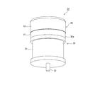
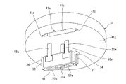
図1に示すように、この実施形態の電動機22は、電動機本体30と、電動機本体30を駆動制御する制御ユニット40を有する。電動機本体30の一端から出力軸32が突出している。
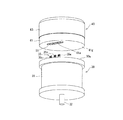
図2に示すように、電動機本体30と制御ユニット40は、別々に製造されたものである。電動機本体30は、三つの入力端子35u,35v,35wを有する電力入力部35を備えている。電動機本体30の出力軸32が突出する方向とは反対側の端面(反出力軸側端面)30aから、各入力端子35u,35v,35wの一端部(突出部)350が突出している。
制御ユニット40の電動機本体30側の面(後述するヒートシンク41の第二面)41gに、中継端子部51が形成されている。中継端子部51に入力端子35u,35v,35wが入ることで、電動機本体30と制御ユニット40が一体化される。
<Configuration of motor>
As shown in FIG. 1, the
As shown in FIG. 2, the electric motor
A
<電動機本体>
電動機本体30は、例えば3相ブラシレスモータで構成されている。図1および図2に示すように、電動機本体30は円柱状のモータハウジング31を有し、モータハウジング31内に、コイルを巻装した円筒状の固定子と、固定子の内側に回転自在に配置された回転子が配置されている。回転子の表面又は内部の円周方向に永久磁石が配置されている。この回転子に連結された出力軸32が、モータハウジング31の軸方向一端部から外部に突出している。
<Motor body>
The electric motor
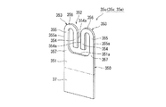
図3に示すように、電動機本体30の反出力軸側端面30aから、各入力端子35u,35v,35wの一端部(突出部)350が突出している。モータハウジング31は、 ハウジング本体31aと蓋部31bとを有する。蓋部31bは、入力端子35u,35v,35wを通す貫通孔33を有する。
各入力端子35u,35v,35wは、反出力軸側端面30aから突出する突出部350と、モータハウジング31内に配置される基端部37とからなる。図4の一点鎖線より上側の部分が突出部350であり、下側の部分が基端部37である。
As shown in FIG. 3, one end portion (projecting portion) 350 of each
Each of the
図4に示すように、突出部350は、長方形の基部351と、二つのU字状部353からなる先端部352とを有する。各U字状部353は、二つの直線部354,355と両者を結合するU字部356とからなり、U字の開口側が基部351側に向いている。外側の直線部355は基部351に連続し、内側の直線部354は基部351に不連続で、基部351の先端部側の端面351aとの間に空間を有する。
二つの直線部354,355は互いに反対側となる外側面354a,355aを有し、外側の直線部355の外側面355aは基部351の外側面351bに連続している。各入力端子35u,35v,35wは銅合金製の板をプレス成形することで作製されたものであり、プレス成形の際に、突出部350の先端部352が図4に示す形状に型抜きされる。
また、各入力端子35u,35v,35wの基端部37が、ハウジング本体31a内のモータ内部回路(固定子のコイル接続部)に接続されている。入力端子35u〜35wを貫通孔33に入れて、ハウジング本体31aに蓋部31bを取り付けることにより、図3に示す状態となる。
As shown in FIG. 4, the projecting
The two
Further, the
<制御ユニット>
図2および図3に示すように、制御ユニット40は、ヒートシンク41と回路基板42と中継端子部51を有する。ヒートシンク41は、銅、アルミニウム等の熱伝導率が高い金属材料からなる円板状部材であり、図1に示すように、電動機22に組み立てられた状態で、電動機本体30の反出力軸側端面30a上に配置されている。
図3に示すように、回路基板42は、ヒートシンク41の電動機本体30とは反対側に配置され、ユニットカバー43で覆われている。回路基板42は、パワー基板44とインサートベース45と制御基板46を有する。パワー基板44は、ヒートシンク41の電動機本体30とは反対側の面(第一面)41fに接触配置される。インサートベース45は、パワー基板44に対して所定距離を保って配置される。制御基板46は、インサートベース45に対して所定距離を保って配置される。
<Control unit>
As shown in FIGS. 2 and 3, the
As shown in FIG. 3, the
≪ヒートシンクの形状≫
図2、図10〜図12に示すように、ヒートシンク41の電動機本体30側の面(第二面)41gに、中継端子部51を収納する収納凹部41aが形成されている。図12に示す収納凹部41aの底面410aは、塗装が施されて非光沢面になっている。また、図3に示すように、ヒートシンク41には、収納凹部41aの底面410aから第一面41fまで貫通する貫通孔41u,41v,41wが形成されている。
収納凹部41aは、図10〜図12に示すように、幅広の中央凹部41bと、この中央凹部41bの長手方向(ヒートシンク41をなす円板の弦方向)の両側面から外方に延長する幅狭の結合用凹部41cとを備えている。各結合用凹部41cの第一面41f側に、中継端子部51をスナップフィット結合させる係合段部41dが形成されている。また、各係合段部41dの第一面41f側に、第一面41fに開口する結合解除孔41eが形成されている。
≪Heat sink shape≫
As shown in FIGS. 2 and 10 to 12, an
As shown in FIGS. 10 to 12, the
≪中継端子部の構成≫
図5および図6に示すように、中継端子部51は、合成樹脂製の端子ホルダー510と、端子ホルダー510に固定された金属製の接続端子55u,55v,55wを有する。端子ホルダー510と接続端子55u,55v,55wは、インサート成形により一体化されている。
端子ホルダー510は、直方体状の本体52とL字状板片53とフック部54とからなる。本体52をなす直方体は、ヒートシンク41の電動機本体30側の面(第二面)41g)に沿わせる基準面521を有する。
本体52の基準面521に三つの案内凹部51u〜51wが形成されている。三つの案内凹部51u〜51wは、本体52の長手方向に所定間隔を保って形成されている。各案内凹部51u〜51wの配置間隔は、入力端子35u,35v,35wの配置間隔に合わせてある。
≪Relay terminal configuration≫
As shown in FIGS. 5 and 6, the
The
Three guide recesses 51 u to 51 w are formed on the
各案内凹部51u〜51wは、基準面521を底面とした四角錐の先端部が切り落とされた形状を有する。つまり、各案内凹部51u〜51wの断面積は、基準面521から基準面521とは反対側の面(反基準面)522に向かうに連れて徐々に小さくなる。
各接続端子55u,55v,55wは、図7に示すように、接続板部55aと、接続板部55aの一端から屈曲して延びる接触板部55bと、を含むL字状部品である。各接続板部55aは、各入力端子35u,35v,35wの二つのU字状部353が挿入される貫通穴55c,55dを有する。接続板部55aの二つの貫通穴55c,55dの間に柱部55eが存在する。
Each of the
As shown in FIG. 7, each of the
図8、図11に示すように、接続板部55aの柱部55eの互いに反対側となる端面55fは、各貫通穴55c,55dに各入力端子35u,35v,35wの各U字状部353が挿入された時に、内側の直線部354の外側面354aが接触する面である。また、各貫通穴55c,55dの柱部55eとは反対側の端面55gは、各貫通穴55c,55dに各入力端子35u,35v,35wの各U字状部353が挿入された時に、外側の直線部355の外側面355aが接触する面である。
図5に示すように、接続端子55u及び55wは、本体52をなす直方体の短手方向一端面における長手方向の両端側に配置され、接続端子55vは、短手方向他端面における接続端子55u及び55wの中間位置に配置されている。
As shown in FIGS. 8 and 11, the end surfaces 55f of the connecting
As shown in FIG. 5, the
図6および図11に示すように、本体52の各案内凹部51u〜51wの底面52aに、接続端子55u,55v,55wの接続板部55aが配置されている。これにより、端子ホルダー510を基準面521から見たときに(図12)、各案内凹部51u〜51wの底面52aに、各接続端子55u,55v,55wの貫通穴55c,55dが存在する。また、接続端子55u,55v,55wの接触板部55bは、本体52の反基準面522側に延びている。
図6および図11に示すように、各案内凹部51u〜51wの底面52aより反基準面522側に、入力端子35u,35v,35wの先端部が配置される空間52bが形成されている。そして、空間52bの反基準面522側が開放されている。つまり、端子ホルダー510の本体52は、空間52bの反基準面522に開口部52cを有する。
図5および図6に示すように、端子ホルダー510のL字状板片53は、本体52をなす直方体の長手方向両端に形成されている。L字状板片53は、本体52の基準面521と同じ面を基端として、反基準面522側に延びている。各L字状板片53の先端にフック部54が形成されている。フック部54は、本体52をなす直方体の長手方向外方に突出している。
As shown in FIGS. 6 and 11, the
As shown in FIGS. 6 and 11, a
As shown in FIGS. 5 and 6, the L-shaped
≪中継端子部のヒートシンクへの取り付け≫
図9〜11に示すように、中継端子部51をヒートシンク41の収納凹部41aに挿入し、端子ホルダー510のフック部54を係合段部41dに係合することにより、中継端子部51は収納凹部41a内に取り付けられる。接続端子55u〜55wの長さは、この状態としたときに、ヒートシンク41の貫通孔41u,41v及び41wを通じて上面側に所定長さだけ突出する長さに設定されている。
≪Attaching the relay terminal to the heat sink≫
As shown in FIGS. 9 to 11, the
≪接続端子55u〜55wの位置検査≫
中継端子部51をヒートシンク41に取り付けた後に、接続端子55u〜55wの位置を検査する。
上述のように、この実施形態では、端子ホルダー510の空間52bの反基準面522側の面が開放されている。つまり、空間52bが反基準面522まで至る開口部52cとなっている。そのため、ヒートシンク41に取り付けられた中継端子部51を端子ホルダー510の基準面521側から見ると、図12に示すように、各接続端子55u〜55wの接続板部55aの背景が、収納凹部41aの底面410aになっている。
≪Position inspection of
After the
As described above, in this embodiment, the surface on the side opposite to the
この状態で、基準面521側から、接続端子55u〜55wの位置をカメラを用いて検査する。具体的には、各接続端子55u〜55wにおいて、接続板部55aの各貫通穴55c,55dの互いに近接する端面位置をカメラで検出する。
この実施形態では、収納凹部41aの底面410aが塗装されて非光沢面になっているため、収納凹部41aの底面410aが光沢面になっている場合と比較して、金属製の接続板部55aに対するコントラストが高い。よって、カメラによる位置検出精度が向上する。
In this state, the positions of the
In this embodiment, since the
≪回路基板の構成の詳細≫
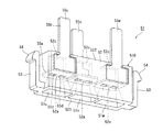
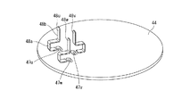
回路基板42のパワー基板44は、例えばインバータを構成する6つのMOSFETなどの発熱量が多い半導体スイッチング素子や、リレー等が上面に配置される金属基板で構成されている。このパワー基板44には、図14に示すように、ヒートシンク41に形成された貫通孔41u,41v,41wに対向する位置に、貫通孔47u,47v,47wが形成されている。また、パワー基板44には、各貫通孔47u,47v,47wに沿ってバスバー48u,48v,48wが、例えば半田付けによって固定されている。
≪Details of circuit board configuration≫
The
各バスバー48u〜48wは、図14に示すように、コ字状部48aと、コ字状部48aの開放端側の上板部に連接されて上方に延長する接触板部48bとで構成されている。バスバー48u,48wは、コ字状部48aの開放端が貫通孔47u,47wの外側の側縁に近接して配置され、バスバー48vは、コ字状部48aの開放端が貫通孔47vの内側の側縁に近接して配置されている。また、各バスバー48u〜48wのコ字状部48aの下板部が、パワー基板44に形成された図示しない配線パターンに接続するように、半田付けにより固定されている。
As shown in FIG. 14, each of the
各バスバー48u〜48wの接触板部48bは、貫通孔47u〜47wを通じて突出する中継端子部51の接続端子55u〜55wと面接触し、バスバー48u〜48wの接触板部48bと接続端子55u〜55wとが最終的に溶接、ロー付け、半田付け等の接合手段によって一体化される。
回路基板42のインサートベース45は、金属板(図示せず)がモールド又は圧入により保持され、外部接続用のコネクタ(図示せず)が一体に形成された合成樹脂製部材であり、このインサートベース45に保持された金属板によって、パワー基板44上の大電流ライン以外の電流ラインが全て構成されている。
The
The
また、インサートベース45には、図15に示すように、貫通孔49u,49v,49wが形成されている。貫通孔49u,49v,49wに、中継端子部51の接続端子55u,55v,55wとバスバー48u,48v,48wの接触板部48bとの接触部が挿入される。
さらに、インサートベース45には、電解コンデンサ、抵抗、コイルの他、ノイズ対策用のセラミックコンデンサ等が実装されている。インサートベース45は、図15に示すように、下面に固定された絶縁性のスペーサ50aを介してパワー基板44にねじ止めされる。インサートベース45のパワー基板44への装着方法は、ねじ止めに限定されるものではなく、任意の固定方法を適用することができる。
Further, as shown in FIG. 15, through
Furthermore, the
回路基板42の制御基板46には制御関連部品が実装されている。制御関連部品には、インバータを構成するスイッチング素子を駆動するマイクロプロセッサ等のICチップが含まれる。制御基板46も、図16に示すように、インサートベース45と同様に、絶縁性のスペーサ50bを介してインサートベース45にねじ止めされる。制御基板46のインサートベース45への装着方法は、ねじ止めに限定されるものではなく、任意の固定方法を適用することができる。
回路基板42を覆うユニットカバー43は、図17に示すように、合成樹脂材で一端を開放した有底円筒状に形成されている。
Control-related components are mounted on the
As shown in FIG. 17, the
≪制御ユニットの組み立て≫
制御ユニット40は以下の方法で組み立てられる。
先ず、ヒートシンク41に中継端子部51を装着する。この装着の際には、先ず、図10に示すように、ヒートシンク41の収納凹部41aの中央凹部41b及び結合用凹部41cに対して、中継端子部51を構成する端子ホルダー510の本体52及びL字状板片53を下側から対向させる。この状態で、端子ホルダー510の本体52及びL字状板片53を中央凹部41b及び結合用凹部41c内に挿入する。このとき、L字状板片53のフック部54が結合用凹部41cの奥側壁面に係合し、L字状板片53が本体52側に撓んだ状態で、結合用凹部41c内に挿入される。
≪Assembly of control unit≫
The
First, the
そして、図9〜図11に示すように、フック部54が、結合用凹部41cに形成された係合段部41dに到達することにより、L字状板片53の外側面が結合用凹部41cの奥壁に接触して、スナップフィット結合状態となる。
このスナップフィット結合状態となると、フック部54が結合用凹部41cの係合段部41dに係合することから、中継端子部51の収納凹部41aから下方への抜け出しが防止されて、中継端子部51がヒートシンク41に保持される。
この状態で、図10および図11に示すように、中継端子部51の基準面(端子ホルダー510の本体52の基準面)521とヒートシンク41の第二面41gが同じ面になるとともに、ヒートシンク41の第一面41fから接続端子55u〜55wが突出する。
9 to 11, when the
In this snap-fit coupled state, the
In this state, as shown in FIGS. 10 and 11, the reference surface of the relay terminal portion 51 (the reference surface of the
なお、中継端子部51の基準面521とヒートシンク41の第二面41gは同一面でなくてもよい。中継端子部51の基準面521をヒートシンク41の第二面41gより凹ませたり、突出させてもよい。
中継端子部51の基準面521をヒートシンク41の第二面41gから突出させる場合には、電動機本体30の反出力軸側端面30aに、突出した中継端子部51の基準面521を受ける凹部を形成することが好ましい。この場合には、突出した基準面521と反出力軸側端面30aの凹部とで、電動機本体30とヒートシンク41との位置決めを行うことができる。
The
When the
次いで、ヒートシンク41の第一面41f上に、パワー基板44をその下面を直接接触させて装着する。このとき、パワー基板44に形成された貫通孔47u〜47w(図14)内に、中継端子部51の接続端子55u〜55wを挿通し、パワー基板44から上方に接続端子55u〜55wを突出させる。そして、接続端子55u〜55wのパワー基板44から上方に突出している部分と、パワー基板44の上面に形成されているバスバー48u〜48wの接触板部48bを接触させる。
次いで、図15に示すように、インサートベース45をパワー基板44上に、スペーサ50aを介してねじ止めすることにより装着する。この場合も、中継端子部51の接続端子55u〜55wとバスバー48u〜48wの接触板部48bを、インサートベース45に形成された貫通孔49u〜49wを通じてインサートベース45の上方に突出させる。この状態で、接続端子55u〜55wとバスバー48u〜48wの接触板部48bとを、溶接、ロー付け、半田付け等の接合手段で接合する。
これにより、接続端子55u〜55wとバスバー48u〜48wとの間を電気的且つ機械的に接続して、パワー基板44と中継端子部51との間の電流路を確保する。
Next, the
Next, as shown in FIG. 15, the
Accordingly, the
次いで、インサートベース45上にスペーサ50bを介して、制御基板46をねじ止めによって装着する。その後、インサートベース45に搭載された部品と制御基板46との信号線接続を行う。その接続方法は、例えばDIP半田接続としても良いし、プレスフィット端子接続しても良いし、コネクタ接続としてもよい。これにより、回路基板42が形成される。図16はこの状態を示す。
次いで、ユニットカバー43で回路基板42を覆い、ユニットカバー43の開口端の内周面をヒートシンク41の上端側(第一面41f側)の外周面に嵌合させることにより、制御ユニット40の組み立てを完了する。図17はこの状態を示す。
Next, the
Next, the
<電動機の組み立て>
電動機22は、以下の方法で組み立てられる。
図2に示すように、電動機本体30の反出力軸側端面30aから突出させた入力端子35u,35v,35wを、制御ユニット40の中継端子部51に向け、電動機本体30を上昇させるか、制御ユニット40を下降させて、両者を相対的に接近させる。
そして、図13に示すように、入力端子35u〜35wを中継端子部51の案内凹部51u〜51w内に挿入すると、各入力端子(第一端子)35u〜35wの突出部350が有する二つのU字状部353が、各接続端子(第二端子)55u〜55wの接続板部55aが有する貫通穴55c,55dに入る。
<Assembly of electric motor>
The
As shown in FIG. 2, the
Then, as shown in FIG. 13, when the
その結果、入力端子35u〜35wと接続端子55u〜55wとが電気的及び機械的に接続される。入力端子35u〜35wの突出部350は、端子ホルダー510の空間52b内に配置される。
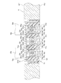
この状態で、各入力端子35u〜35wにおける二つのU字状部353は、内側の直線部354の外側面354aが、接続板部55aの柱部55eの互いに反対側となる端面55fに接触し、外側の直線部355の外側面355aが柱部55eとは反対側の端面55gに接触する。つまり、各接続端子55u〜55wの接続板部55aと各入力端子35u〜35wの先端部352とが、板幅方向の四箇所で接触する。
As a result, the
In this state, the two
ここで、U字部356がU字の開口を広げようとする弾性変形に伴い、内側の直線部354の外側面354aが柱部55eの端面55fに押し付けられる。この押し付け力は、二つのU字状部353で互いに反対向きの力となるため、端面55fと外側面354aとの間に大きな圧接力が生じる。また、基部351と外側の直線部355との境界部357が二つの直線部355間を広げようとする弾性変形に伴い、直線部355の外側面355aが貫通穴55c,55dの端面55gに押し付けられる。
そして、接続端子55u〜55wは、パワー基板44のバスバー(回路基板42の電力出力部)48u〜48wに接続されているため、入力端子35u〜35wと接続端子55u〜55wとが接続されることにより、電動機本体30の電力入力部35と制御ユニット40の電力出力部とが電気的に接続された状態になる。
Here, the
And since the
<実施形態の効果>
この実施形態の電動機22は以下の効果を有する。
ヒートシンク41が中継端子部51を保持することで、電動機本体30の入力端子35u〜35wと、制御ユニット40のパワー基板44及びインサートベース45との間の電流路を容易に形成することができる。
しかも、入力端子35u〜35wと中継端子部51の接続端子55u〜55wとは略直線上に接続されるため、電動機本体30と制御ユニット40との間の電流路を最短とすることができるとともに、電気抵抗を最小化することができる。また、電流路が外部に露出してないので、外部からのノイズの影響を受けにくいとともに、電流路から外部に放出されるノイズも減少させることができる。
<Effect of embodiment>
The
Since the
Moreover, since the
また、中継端子部51が、角錐面を有する案内凹部51u〜51wを有するため、電動機本体30の入力端子35u〜35wと、中継端子部51の接続端子55u〜55wの接続板部55aにおける貫通穴55c,55dとの間に位置ずれが生じている場合でも、案内凹部51u〜51wで入力端子35u〜35wが案内されて、入力端子35u〜35wと接続端子55u〜55wとの接続を確実に行うことができる。
また、各入力端子35u〜35wの先端部352が図4に示す形状を有することで、各接続端子55u〜55wの接続板部55aと各入力端子35u〜35wの二つのU字状部353からなる先端部352とが、板幅方向の四箇所で接触し、接続板部55aの貫通穴55c,55dの端面55fと内側の直線部354の外側面354aとの間、および端面55gと外側の直線部355の外側面355aとの間に圧接力が生じる。
これにより、 入力端子35u〜35wと接続端子55u〜55wとの接続状態が安定化し、良好な接続状態が継続するため、制御ユニット40と電動機本体30との安定的な接続状態が長期に渡って確保でき、接続信頼性が向上する。
Moreover, since the
Moreover, since the front-end |
As a result, the connection state between the
さらに、電動機本体30と制御ユニット40とを別工程で組み立てることができる。電動機本体30の組み立て工程と、制御ユニット40の組み立て構成とは同一工場で行ってもよく、別工場で行ってもよい。
また、端子ホルダー510の本体52は、空間52bの反基準面522側の面が開放されている(開口部52cを有する)ため、中継端子部51をインサート成形で製造する際に使用する金型の作製が容易になる。これに伴い、上述した接続端子55u〜55wの位置検査時に、接続板部55aの背景が収納凹部41aの底面410aとなるが、底面410aが非光沢面になっているため、底面410aが光沢面になっている場合と比較して位置検出精度が向上する。
接続端子55u〜55wの位置検査は製造ライン内で全製品に対して行うため、カメラによる位置検出精度が向上することにより、電動機22の製造コストが大幅に低減される効果が期待できる。
Furthermore, the electric motor
Further, since the
Since the position inspection of the
<図4とは異なる例>
入力端子35u〜35wの先端部352の形状は、開口側を基部351側に向けた二つのU字状部353からなるものであれば、図4の形状に限定されない。図4とは異なる例を図18に示す。
図18の入力端子35u〜35wは、銅合金製の板をプレス成形した後に曲げ加工を行うことで作製されたものである。図18の一点鎖線より上側の部分が、反出力軸側端面30aから突出する突出部350であり、下側の部分がモータハウジング31内のモータ内部回路(固定子のコイル接続部)に接続される基端部37である。
図18の入力端子35u〜35wは、図4の入力端子35u〜35wと比較して、二つの直線部354,355の互いに反対側となる外側面354a,355aの面積が大きいため、接続端子55u〜55wの柱部55eの端面55fおよび貫通穴55c,55dの端面55gに対する押し付け力が大きい。よって、図18の入力端子35u〜35wを有することで、図4の入力端子35u〜35wを有する場合よりも、制御ユニット40と電動機本体30との接続の信頼性を高くすることができる。
<An example different from FIG. 4>
If the shape of the front-end |
The
The
<備考>
なお、入力端子35u〜35wは、制御ユニット40との最終的な組み立て工程の前までに、電動機本体30の貫通孔33u〜33wに挿通して、基端部37を固定子のコイル接続部に接続すればよい。
電動機本体30を輸送する場合には、入力端子35u〜35wを装着しない状態で搬送することにより、搬送過程での入力端子35u〜35wの曲がりや損傷を防止することができる。
また、入力端子35u〜35wは、引張強度および耐力が高く、導電率が高い材料であれば、銅合金以外の材料で形成されていてもよい。
<Remarks>
The
When the electric motor
Further, the
[実施形態の電動機を車両の電動パワーステアリング装置に適用した例]
図19に示す車両1は、左右の転舵輪となる前輪2FR,2FLと後輪2RR,2RLを備えている。前輪2FR,2FLは、車載用装置としての電動パワーステアリング装置3によって転舵される。
電動パワーステアリング装置3は、ステアリングホイール11を有し、ステアリングホイール11に運転者から作用される操舵力が、ステアリングシャフト12に伝達される。ステアリングシャフト12は、入力軸12aと出力軸12bとを有する。入力軸12aの一端はステアリングホイール11に連結され、他端は操舵トルクセンサ13を介して出力軸12bの一端に連結されている。
[Example in which the electric motor of the embodiment is applied to an electric power steering device of a vehicle]
The vehicle 1 shown in FIG. 19 includes front wheels 2FR, 2FL and rear wheels 2RR, 2RL which are left and right steered wheels. The front wheels 2FR and 2FL are steered by an electric
The electric
そして、出力軸12bに伝達された操舵力は、ユニバーサルジョイント14を介してロアシャフト15に伝達され、さらに、ユニバーサルジョイント16を介してピニオンシャフト17に伝達される。ピニオンシャフト17に伝達された操舵力はステアリングギヤ18を介してタイロッド19に伝達され、転舵輪としての前輪2FR,2FLを転舵させる。ここで、ステアリングギヤ18は、ピニオンシャフト17に連結されたピニオン18aとこのピニオン18aに噛合するラック18bとを有する、ラックアンドピニオン形式に構成されている。そして、ピニオン18aに伝達された回転運動が、ラック18bで車幅方向の直進運動に変換される。
The steering force transmitted to the
ステアリングシャフト12の出力軸12bには、操舵補助力を出力軸12bに伝達する操舵補助機構20が連結されている。この操舵補助機構20は、出力軸12bに連結された減速ギヤ21と、実施形態の電動機22とを備えている。減速ギヤ21は、例えばウォームギヤ機構で構成されている。電動機22は、上述のように、電動機本体30とこれを駆動制御する制御ユニット40とが一体化されたものである。電動機本体30の出力軸32が減速ギヤ21に連結されている。
操舵トルクセンサ13は、ステアリングホイール11に付与されて入力軸12aに伝達された操舵トルクを検出する。この操舵トルクセンサ13は、例えば、操舵トルクを、入力軸12a及び出力軸12b間に介挿した図示しないトーションバーの捩れ角変位に変換し、この捩れ角変位を抵抗変化や磁気変化に変換して検出する構成とされている。
A
The
制御ユニット40には、バッテリ27から直流電源が供給され、操舵トルクセンサ13から操舵トルク検出値が入力されるとともに、車速センサ26から車速検出値が入力される。制御ユニット40は、操舵トルク検出値及び車速検出値に基づいて操舵補助指令値を算出し、算出した操舵補助指令値に基づいて、電動機本体30を、必要な操舵補助トルクを発生するように回転駆動する。
なお、各実施形態の電動機22の用途は電動パワーステアリング装置だけでなく、各実施形態の電動機22は、電動ブレーキ等の他の任意の車載用装置の電動機として使用することができる。
The
In addition, the use of the
1 車両
3 電動パワーステアリング装置
20 操舵補助機構
21 減速ギヤ
22 電動機
30 電動機本体
30a 電動機本体の反出力側端面
31 モータハウジング
31a ハウジング本体
31b 蓋部
32 出力軸
35 電力入力部
35u〜35w 入力端子(第一端子)
350 入力端子の突出部
351 突出部の基部
351b 基部の外側面
352 突出部の先端部
353 U字状部
354 U字状部を構成する内側の直線部
354a 内側の直線部の外側面
355 U字状部を構成する外側の直線部
355a 外側の直線部の外側面
356 U字状部を構成するU字部
37 入力端子の基端部
40 制御ユニット
41 ヒートシンク
41a ヒートシンクの収納凹部
410a 収納凹部の底面
42 回路基板
48u〜48w パワー基板のバスバー(回路基板の電力出力部)
51 中継端子部
510 端子ホルダー
51u〜51w 案内凹部
52 端子ホルダーの本体
521 端子ホルダーの基準面
522 端子ホルダーの反基準面
52a 案内凹部の底面
52b 入力端子の先端部が配置される空間
52c 端子ホルダーの開口部
55u〜55w 接続端子(第二端子)
55a 接続端子の接続板部
55b 接続端子の接触板部
55c,55d 接続板部の貫通穴
55e 接続板部の柱部
55f 柱部の互いに反対側となる端面
55g 貫通穴の柱部とは反対側の端面
DESCRIPTION OF SYMBOLS 1
350
51 Relay
55a Connection plate portion of the
Claims (3)
前記電動機本体の一端から突出した出力軸と、
前記電動機本体が有する電力入力部と、
前記電力入力部が有する入力端子であって、前記出力軸が突出する方向とは反対側の反出力軸側端面から突出する突出部を有し、前記突出部の先端部は、開口側を基部側に向けた二つのU字状部からなる入力端子と、
前記電動機本体を駆動制御する制御ユニットであって、前記電動機本体の前記反出力軸側端面に配置されたヒートシンクと、前記ヒートシンクの前記電動機本体とは反対側に配置された回路基板と、前記ヒートシンクの前記電動機本体側の面に形成された収納凹部に配置され、前記回路基板の電力出力部と前記電動機本体の前記電力入力部とを電気的に接続する中継端子部と、を有する制御ユニットと、
前記中継端子部を構成する接続端子であって、二つの貫通穴とこれらの貫通穴の間に存在する柱部とを有する接続板部を備え、前記二つの貫通穴に、前記先端部が有する二つのU字状部がそれぞれ挿入され、前記U字状部を構成する二つの直線部のうち内側の直線部の外側面が前記柱部の互いに反対側となる端面に接触し、外側の直線部の外側面が前記柱部とは反対側の端面に接触する接続端子と、
前記中継端子部を構成する端子ホルダーであって、前記ヒートシンクの前記電動機本体側の面に沿った基準面と、前記基準面に形成された前記入力端子の案内凹部と、前記基準面とは反対側の反基準面と、を有し、前記案内凹部の底面に前記接続端子の前記接続板部が配置され、前記底面より前記反基準面側に前記入力端子の前記先端部が配置される空間が形成されている端子ホルダーと、
を備え、
前記接続端子の前記二つの貫通穴に、前記入力端子の前記先端部が有する二つのU字状部がそれぞれ挿入されて、前記内側の直線部の外側面が前記柱部の互いに反対側となる端面に接触し、前記外側の直線部の外側面が前記柱部とは反対側の端面に接触することで、前記電力出力部と前記電力入力部とが電気的に接続されている電動機。 An electric motor body,
An output shaft protruding from one end of the electric motor body;
An electric power input section of the electric motor body;
The power input portion has an input terminal, and has a protruding portion protruding from the opposite end surface of the output shaft opposite to the direction in which the output shaft protrudes, and the tip of the protruding portion is based on the opening side. An input terminal consisting of two U-shaped parts facing the side,
A control unit for driving and controlling the electric motor main body, the heat sink disposed on the opposite end surface of the electric motor main body, a circuit board disposed on the heat sink opposite to the electric motor main body, and the heat sink A control unit having a relay terminal portion that is disposed in a housing recess formed on the surface of the motor body and electrically connects the power output portion of the circuit board and the power input portion of the motor body. ,
A connection terminal constituting the relay terminal portion, comprising a connection plate portion having two through holes and a column portion existing between the through holes, and the tip portion is provided in the two through holes. Two U-shaped portions are respectively inserted, and the outer surface of the inner straight portion of the two straight portions constituting the U-shaped portion is in contact with the opposite end surfaces of the column portion, and the outer straight line A connection terminal in which the outer surface of the part contacts the end surface opposite to the column part;
A terminal holder constituting the relay terminal portion, wherein a reference surface along a surface of the heat sink on the motor body side, a guide recessed portion of the input terminal formed on the reference surface, and the reference surface are opposite to each other A space in which the connection plate portion of the connection terminal is disposed on the bottom surface of the guide recess, and the tip portion of the input terminal is disposed on the anti-reference surface side from the bottom surface. A terminal holder formed with,
With
Two U-shaped portions of the tip of the input terminal are inserted into the two through holes of the connection terminal, respectively, and the outer surfaces of the inner straight portions are opposite to the pillar portions. The electric motor in which the electric power output unit and the electric power input unit are electrically connected by contacting an end surface and contacting an outer surface of the outer straight portion with an end surface opposite to the column portion.
二つの貫通穴とこれらの貫通穴の間に存在する柱部とを有する接続板部を備えた第二端子と、からなり、
前記二つの貫通穴に、前記先端部が有する二つのU字状部がそれぞれ挿入され、前記U字状部を構成する二つの直線部のうち内側の直線部の外側面が前記柱部の互いに反対側となる端面に接触し、外側の直線部の外側面が前記柱部とは反対側の端面に接触している端子接続構造。 A first terminal having a tip portion composed of two U-shaped portions with the opening side facing the base side;
A second terminal provided with a connecting plate part having two through holes and a pillar part existing between these through holes,
Two U-shaped portions of the tip portion are respectively inserted into the two through holes, and an outer surface of an inner straight portion of the two straight portions constituting the U-shaped portion is mutually connected to the pillar portions. The terminal connection structure which contacts the end surface which becomes an other side, and the outer side surface of an outer side linear part is contacting the end surface on the opposite side to the said column part.
Priority Applications (1)
| Application Number | Priority Date | Filing Date | Title |
|---|---|---|---|
| JP2015233123A JP2017103848A (en) | 2015-11-30 | 2015-11-30 | Electric motor, on-vehicle device with the same, and terminal connection structure |
Applications Claiming Priority (1)
| Application Number | Priority Date | Filing Date | Title |
|---|---|---|---|
| JP2015233123A JP2017103848A (en) | 2015-11-30 | 2015-11-30 | Electric motor, on-vehicle device with the same, and terminal connection structure |
Publications (1)
| Publication Number | Publication Date |
|---|---|
| JP2017103848A true JP2017103848A (en) | 2017-06-08 |
Family
ID=59017309
Family Applications (1)
| Application Number | Title | Priority Date | Filing Date |
|---|---|---|---|
| JP2015233123A Pending JP2017103848A (en) | 2015-11-30 | 2015-11-30 | Electric motor, on-vehicle device with the same, and terminal connection structure |
Country Status (1)
| Country | Link |
|---|---|
| JP (1) | JP2017103848A (en) |
Cited By (5)
| Publication number | Priority date | Publication date | Assignee | Title |
|---|---|---|---|---|
| JP2021072739A (en) * | 2019-11-01 | 2021-05-06 | 三菱電機株式会社 | Rotary electric machine and manufacturing method of rotary electric machine |
| CN112928873A (en) * | 2019-12-05 | 2021-06-08 | 深圳市高科润电子有限公司 | Novel electric automobile motor control box |
| JP7305003B1 (en) | 2022-04-21 | 2023-07-07 | 三菱電機株式会社 | Armature for rotating electrical machine and method for manufacturing armature for rotating electrical machine |
| WO2023210347A1 (en) * | 2022-04-29 | 2023-11-02 | 株式会社デンソー | Power conversion device and rotating electric machine unit |
| WO2024069830A1 (en) * | 2022-09-29 | 2024-04-04 | 三菱電機株式会社 | Rotary electric machine and method for manufacturing same |
-
2015
- 2015-11-30 JP JP2015233123A patent/JP2017103848A/en active Pending
Cited By (6)
| Publication number | Priority date | Publication date | Assignee | Title |
|---|---|---|---|---|
| JP2021072739A (en) * | 2019-11-01 | 2021-05-06 | 三菱電機株式会社 | Rotary electric machine and manufacturing method of rotary electric machine |
| JP6995102B2 (en) | 2019-11-01 | 2022-01-14 | 三菱電機株式会社 | Rotating machine and manufacturing method of rotating machine |
| CN112928873A (en) * | 2019-12-05 | 2021-06-08 | 深圳市高科润电子有限公司 | Novel electric automobile motor control box |
| JP7305003B1 (en) | 2022-04-21 | 2023-07-07 | 三菱電機株式会社 | Armature for rotating electrical machine and method for manufacturing armature for rotating electrical machine |
| WO2023210347A1 (en) * | 2022-04-29 | 2023-11-02 | 株式会社デンソー | Power conversion device and rotating electric machine unit |
| WO2024069830A1 (en) * | 2022-09-29 | 2024-04-04 | 三菱電機株式会社 | Rotary electric machine and method for manufacturing same |
Similar Documents
| Publication | Publication Date | Title |
|---|---|---|
| JP4580999B2 (en) | Motor control unit | |
| JP2017103848A (en) | Electric motor, on-vehicle device with the same, and terminal connection structure | |
| US10971914B2 (en) | Circuit assembly | |
| US10971976B2 (en) | Electric drive device and electric power steering device | |
| JP4474341B2 (en) | Electric power steering device | |
| KR101729809B1 (en) | Electronic control device | |
| US7932651B2 (en) | Motor for controller integrated electric power steering apparatus and electric power steering apparatus | |
| JP4410242B2 (en) | Electronic control device and manufacturing method thereof | |
| EP3082232B1 (en) | Electronic control unit, electric power steering device, and vehicle | |
| JP5403789B2 (en) | Current detector assembly structure | |
| US9184640B2 (en) | Motor controller and production method of the same | |
| JP5466679B2 (en) | Electronic circuit device for electric actuator | |
| JP2017103849A (en) | Electric motor, on-vehicle device with the same, and terminal connection structure | |
| CN111264021B (en) | Electric drive device and electric power steering device | |
| CN105453259A (en) | Lead frame, electronic control device using lead frame, and lead-frame mounting method | |
| US9513341B2 (en) | Current detection apparatus | |
| JP4556651B2 (en) | Electronic control device, electric motor with electronic control device | |
| JP5946666B2 (en) | Electric actuator | |
| JP2011117853A (en) | Current detector | |
| JP5229612B2 (en) | Electric power steering device | |
| JP2017077149A (en) | Electric motor and on-vehicle device including the same, and inspection device and power input section inspection method | |
| JP2017077150A (en) | Electric motor and on-vehicle device including the same, and inspection apparatus and power input section inspection method | |
| JP2004125767A (en) | Sensor apparatus | |
| WO2022054729A1 (en) | Capacitor | |
| JP5967069B2 (en) | Electronic control unit, electric power steering apparatus and vehicle |