JP2017100352A - Foil film - Google Patents
Foil film Download PDFInfo
- Publication number
- JP2017100352A JP2017100352A JP2015234975A JP2015234975A JP2017100352A JP 2017100352 A JP2017100352 A JP 2017100352A JP 2015234975 A JP2015234975 A JP 2015234975A JP 2015234975 A JP2015234975 A JP 2015234975A JP 2017100352 A JP2017100352 A JP 2017100352A
- Authority
- JP
- Japan
- Prior art keywords
- foil
- adhesive layer
- layer
- film
- foil film
- Prior art date
- Legal status (The legal status is an assumption and is not a legal conclusion. Google has not performed a legal analysis and makes no representation as to the accuracy of the status listed.)
- Pending
Links
Images


Abstract
Description
本発明は、箔フィルムに関し、さらに詳細には、箔フィルムを利用してメディアに所望の図柄などを転写するようにした箔押し装置に用いて好適な箔フィルムに関する。 The present invention relates to a foil film, and more particularly, to a foil film suitable for use in a foil pressing apparatus that uses a foil film to transfer a desired pattern or the like to a medium.
なお、本明細書において「メディア」とは、普通紙などの紙類よりなる各種の記録媒体は勿論のこと、PVC、ポリエステルなどの樹脂材料やアルミ、鉄、木材、布、皮革のような各種の材料が含まれるものとする。 In this specification, the term “media” refers to various recording media such as plain paper, various resin materials such as PVC, polyester, aluminum, iron, wood, cloth, and leather. The following materials shall be included.
従来より、箔フィルムを利用して、当該箔フィルムをメディアに転写することにより、メディアに所望の図柄などを転写するようにした箔押し装置として、例えば、特許文献1に開示された技術が知られている。 Conventionally, for example, a technique disclosed in Patent Document 1 is known as a foil pressing device that uses a foil film to transfer a desired pattern or the like to the medium by transferring the foil film to the medium. ing.
この特許文献1に記載された箔押し装置100は、パーソナルコンピューター102からの入力に応じて駆動し、パーソナルコンピューター102に記憶された箔押し駆動プログラムによってメディア104に対して箔押し処理を行うものである。
The
そして、この箔押し装置100は、平板状のベース部材106の上面において、前方側および後方側に摺動自在にテーブル108が設けられており、このテーブル108上にはメディア104を保持する保持部材110が設けられている。
The
また、ベース部材106の後方側においては、門型で立設された支持部材112が設けられ、この支持部材112には左方側および右方側に摺動自在に設けられたスライダ114が設けられている。
Further, on the rear side of the
さらに、このスライダ114には、上方側および下方側に摺動自在に設けられたスライダ116が設けられ、スライダ116には、先端部が所定の温度で加熱されたペン(本明細書においては、「先端部が所定の温度範囲で加熱されたペン」を「熱ペン」と適宜に称する。)118が把持されている。
Further, the
こうした構成により箔押し装置100においては、保持部材110に保持されたメディア104に対する熱ペン118の相対的な位置関係が三次元方向に移動可能となっている。
With this configuration, in the
以上の構成において、メディア104に対して箔押し処理を行う場合には、パーソナルコンピューター102および箔押し装置100が起動した状態で保持部材110にメディア104を保持する。
In the above configuration, when the foil pressing process is performed on the
次に、メディア104上に箔フィルムを固定的に載置し、パーソナルコンピューター102に記憶された箔押し駆動プログラムによって、箔押し装置100により箔押し処理を実行する。
Next, the foil film is fixedly placed on the
すると、箔押し装置100においては、箔フィルムを介してメディア104上に熱ペン118の先端部を押しつけながら、パーソナルコンピューター102に記憶された図形データに基づいて熱ペン118を走査する。
Then, the foil pressing
このとき、熱ペン118の先端部が加熱されているため、メディア104上において熱ペン118の先端部が押しつけられた領域に、熱ペン118による熱と圧力によって箔フィルムが転写(熱転写)されて、メディア104上に箔押し処理が施されることとなる。
At this time, since the tip of the
こうした箔押し装置100による箔押し処理では、メディア104に形成された図形たる成果物は、一般的な印刷などの処理では表現し難い金属感や光沢による高級感を備えたものとなる。
In such a foil stamping process performed by the
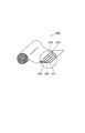
ここで、図2には、箔押し装置100などの各種の箔押し装置に用いられている従来の箔フィルムの断面構造を模式的に示した説明図が示されている。
Here, FIG. 2 is an explanatory view schematically showing a cross-sectional structure of a conventional foil film used in various foil pressing devices such as the
この箔フィルム200は、ベースフィルム202と、離型層204と、着色層206と、蒸着層208と、接着層210とが順次積層されて形成されている。
The
箔押し装置100を用いて箔フィルム200を熱転写する場合、上記したように箔フィルム200をメディア104上に載置して、熱ペン118で加圧および加熱することになる。
When the
これにより、接着層210がメディア104に接着して、離型層204がベースフィルム202から剥がされて転写が行われる。
As a result, the
この転写の際に箔フィルム200をメディア104に固定していないと、メディア104上で箔フィルム200がずれてしまったり皺がよってしまったりして、成果物の品質が劣化してしまうものであった。
If the
このため、メディア100上に箔フィルム200を粘着テープにより固定する手法が提案されているが、この手法は固定のための手間がかかるのみならず、箔フィルム200に皺をよせずにメディア104に綺麗に固定することが困難であるという問題点があった。
For this reason, a method for fixing the
また、メディア100上に箔フィルム200を粘着テープにより固定する手法以外の手法として、エアーを利用してメディア100上に箔フィルム200を吸着させたり、ロールtoロールのフィルム送り機構を搭載することにより、箔フィルム200をメディア104に固定する手法が提案されているが、これらの手法ではシステムがコスト高になるという問題点があった。
Further, as a method other than the method of fixing the
本発明は、従来の技術の有する上記したような種々の問題点に鑑みてなされたものであり、その目的とするところは、コスト高を招来することなく、メディアに容易に固定することができるようにした箔フィルムを提供しようとするものである。 The present invention has been made in view of the above-described various problems of the prior art, and an object of the present invention is to be easily fixed to a medium without incurring high costs. The present invention intends to provide a foil film.
上記目的を達成するために、本発明による箔フィルムは、メディアへの箔押し処理の際に当該メディアと対向して配置される面に、粘着力があまり強くなく貼り付けおよび剥離自在な粘着層である弱粘着層を形成するようにしたものである。 In order to achieve the above object, the foil film according to the present invention is a pressure-sensitive adhesive layer that has a low adhesive force and can be applied to and peeled off from a surface disposed opposite to the media during the foil pressing process on the media. A weak adhesive layer is formed.
従って、本発明による箔フィルムによれば、エアーや送り機構を利用するなどのコスト高を招来するシステムを用いる必要がなく、弱粘着層を介して箔フィルムをメディアへ容易に固定することができる。
Therefore, according to the foil film of the present invention, it is not necessary to use a costly system such as using air or a feeding mechanism, and the foil film can be easily fixed to the media via the weak adhesive layer. .
即ち、本発明による箔フィルムは、メディアへ箔押し処理を行う際に用いる箔フィルムにおいて、ベースフィルムと、離型層と、着色層と、接着層と、弱粘着層とを順次積層して形成したものである。 That is, the foil film according to the present invention is formed by sequentially laminating a base film, a release layer, a colored layer, an adhesive layer, and a weak adhesive layer in a foil film used when performing a foil pressing process on a medium. Is.
また、本発明による箔フィルムは、メディアへ箔押し処理を行う際に用いる箔フィルムにおいて、ベースフィルムと、離型層と、着色層と、蒸着層と、接着層と、弱粘着層とを順次積層して形成したものである。 Further, the foil film according to the present invention is a foil film used when performing a foil pressing process on a medium, and a base film, a release layer, a colored layer, a vapor deposition layer, an adhesive layer, and a weak adhesive layer are sequentially laminated. Formed.
また、本発明による箔フィルムは、上記した本発明による箔フィルムにおいて、上記弱粘着層は、粘着力が1〜3N/cmであるようにしたものである。 The foil film according to the present invention is the above-described foil film according to the present invention, wherein the weak adhesive layer has an adhesive strength of 1 to 3 N / cm.
また、本発明による箔フィルムは、上記した本発明による箔フィルムにおいて、上記弱粘着層は、アクリル系樹脂よりなり、厚さが1〜2μm(16g〜20g/m2)であるようにしたものである。 The foil film according to the present invention is the above-described foil film according to the present invention, wherein the weakly adhesive layer is made of an acrylic resin and has a thickness of 1 to 2 μm (16 g to 20 g / m 2 ). It is.
本発明は、以上説明したように構成されているので、コスト高を招来することなく、メディアに容易に固定することができるようにした箔フィルムを提供することができるという優れた効果を奏する。 Since the present invention is configured as described above, there is an excellent effect that it is possible to provide a foil film that can be easily fixed to a medium without incurring high costs.
以下、添付の図面を参照しながら、本発明による箔押しフィルムの実施の形態の一例を詳細に説明することとする。 Hereinafter, an example of an embodiment of a foil stamped film according to the present invention will be described in detail with reference to the accompanying drawings.
なお、以下の説明においては、上記した従来の技術における構成と同一または相当する構成については、上記した従来の技術の説明において用いた符号と同一の符号を付して示すことにより、その構成ならびに作用の詳細な説明は省略する。
In the following description, components that are the same as or equivalent to those in the above-described conventional technology are denoted by the same reference numerals as those used in the description of the above-described conventional technology, and the configuration and Detailed description of the operation is omitted.
ここで、図3(a)には、本発明による箔フィルムの断面構造を模式的に示した説明図が示されている。 Here, FIG. 3A shows an explanatory view schematically showing the cross-sectional structure of the foil film according to the present invention.
この箔押しフィルム10は、メディア104への箔押し処理の際にメディア104と対向して配置される面、即ち、接着層210のメディア104と対向する面に、粘着力があまり強くなく貼り付けおよび剥離自在な粘着層である弱粘着層12が形成されている点において、従来の箔フィルム200と異なる。
The foil-pressing
より詳細には、箔フィルム10は、ベースフィルム202と、離型層204と、着色層206と、蒸着層208と、接着層210と、弱粘着層12とが順次積層されて形成されている。
More specifically, the
ここで、箔フィルム10におけるベースフィルム202、離型層204、着色層206、蒸着層208および接着層210については、従来の技術による箔フィルム200と同一の構成のものを用いることが可能である。
Here, the
具体的には、例えば、株式会社村田金箔製の「SV 3合金」などを用いることができる。 Specifically, for example, “SV 3 alloy” manufactured by Murata Gold Leaf Co., Ltd. can be used.
この株式会社村田金箔製の「SV 3合金」によれば、ベースフィルム202はPETフィルムよりなりその厚さは12μmであり、離型層204はWAX系樹脂よりなりその厚さは0.05μmであり、着色層206はアクリル系樹脂と染料よりなりその厚さは1.0μmであり、蒸着層208はアルミよりなりその厚さは、0.05μmであり、接着層210はアクリル系樹脂よりなりその厚さは、1.5μmである。
According to “SV 3 alloy” manufactured by Murata Gold Leaf Co., Ltd., the
また、弱粘着層12は、その粘着力が1〜3N/cm程度であることが好ましく、例えば、アクリル系樹脂よりなり、その厚さは、例えば、1.0μmとすることができる。
Further, the weak
弱粘着層12は、上記した構成を備えているため、常温(5℃〜35℃)で箔フィルム10をメディア104へ貼り付けて固定することができるとともに、メディア104に貼り付けて固定した箔フィルム10をメディア104から剥離することが可能である。
Since the weak
即ち、箔フィルム10をメディア104に貼り付けた後に、箔フィルム10やメディア14を損傷することなく箔フィルム10をメディア104から剥離して、剥離した箔フォルム10を再度メディア104へ貼り付けることができる。
That is, after the
従って、箔フィルム10のメディア104への固定作業が容易になり、箔フィルム10のメディア104への固定の際に仮に位置ずれや皺が寄ってしまっても、箔フィルム10をメディア104から剥離して、剥離した箔フィルム10を再度メディア104へ貼り付けることが可能であるので、メディア104への箔フィルム10の固定状態を容易に修正することができる。
Therefore, the fixing operation of the
以上の構成の箔フィルム10を用いて、例えば、箔押し装置100を利用してメディア104への箔押し処理を行うと、熱ペン118による熱と圧力によって箔フィルム10の接着層210が溶融してメディア104と固着し、箔フィルム10の熱転写が行われる(図3(b)を参照する。)。
When the
本願発明者の実験によれば、従来の箔押し装置100を用いて、メディア104として坪量122g/m2の色画用紙に、ベースフィルム202と離型層204と着色層206と蒸着層208と接着層210との各層については株式会社村田金箔製の「SV 3合金」と同一の構成とし、弱粘着層12としてアクリル系樹脂よりなる厚さ1.0μmの層を用いた箔フィルム10を転写する場合には、熱ペン118の温度を100〜150℃とし、熱ペン118の筆圧を80gfとし、熱ペン118の走査速度を10〜30mm/secとすると、極めて良好な転写結果が得られた。
According to the experiment of the present inventor, the
以上において説明したように、本発明による箔押しフィルム10は、弱粘着層12を設けるようにしたため、エアーを利用するなどのコスト高を招来するシステムを用いる必要がなく、弱粘着層12を介して箔フィルム10をメディア104へ容易かつ剥離自在に固定することができるようになる。
As described above, since the foil-stamped
なお、上記した実施の形態は、以下の(1)乃至(8)に示すように変形するようにしてもよい。 The embodiment described above may be modified as shown in the following (1) to (8).
(1)上記した実施の形態においては、弱粘着層12は、例えば、アクリル系樹脂よりなり、その厚さは、例えば、1.0μmとしたが、これに限られるものではないことは勿論である。弱粘着層12は、ウレタン系樹脂よりなり、その厚さは、2.0μmとしてもよい。
(1) In the above-described embodiment, the weak
(2)上記した実施の形態においては、ベースフィルム202は、例えば、PETフィルムよりなり、その厚さは、例えば、12μmとしたが、これに限られるものではないことは勿論である。ベースフィルム202は、PETフィルムよりなり、その厚さは、16μmとしてもよい。
(2) In the above-described embodiment, the
(3)上記した実施の形態においては、離型層204は、例えば、WAX系樹脂よりなり、その厚さは、例えば、0.05μmとしたが、これに限られるものではないことは勿論である。離型層204は、シリコーン系樹脂よりなり、その厚さは、0.1μmとしてもよい。
(3) In the above-described embodiment, the
(4)上記した実施の形態においては、着色層206は、例えば、アクリル系樹脂と染料よりなり、その厚さは、例えば、1.0μmとしたが、これに限られるものではないことは勿論である。着色層206は、アクリル系樹脂と顔料よりなり、その厚さは、15μmとしてもよい。
(4) In the above-described embodiment, the
(5)上記した実施の形態においては、蒸着層208は、例えば、アルミよりなり、その厚さは、例えば、0.05μmとしたが、これに限られるものではないことは勿論である。金属感や光沢感を出さずに純色を表現するために、蒸着層208を設けないようにしてもよい。
(5) In the above-described embodiment, the
(6)上記した実施の形態においては、接着層210は、例えば、アクリル系樹脂よりなり、その厚さは、例えば、1.5μmとしたが、これに限られるものではないことは勿論である。接着層210は、ウレタン系樹脂やオレフィン系樹脂、ハクビ系樹脂などよりなり、その厚さは、2.0μmとしてもよい。
(6) In the above-described embodiment, the
(7)上記した実施の形態においては、弱粘着層12の粘着力は、例えば、1〜3N/cmとしたが、これに限られるものではないことは勿論である。さらに粘着力が必要なメディアに対し、弱粘着層12の粘着力は、3〜5N/cmとしもよい。
(7) In the above-described embodiment, the adhesive force of the weak
(8)上記した実施の形態ならびに上記した(1)乃至(7)に示す変形例は、適宜に組み合わせるようにしてもよい。 (8) You may make it combine suitably the embodiment shown above and the modification shown in said (1) thru | or (7).
本発明は、金属感や光沢による高級感を備えた印刷を行う箔押し装置などの箔フィルムとして用いて好適であり、サイン分野、デザイン分野、ギフト分野、名入れ分野、クラフト分野、ホビー分野などでの利用が期待される。 The present invention is suitable for use as a foil film of a foil stamping apparatus or the like that performs printing with a high-class feeling due to a metallic feeling or gloss, and is used in a sign field, a design field, a gift field, a name field, a craft field, a hobby field, and the like. Is expected to be used.
10,200 箔フィルム、12 弱粘着層、202 ベースフィルム、204 離型層、206 着色層、208 蒸着層、210 接着層、100 箔押し装置、118 熱ペン 10,200 foil film, 12 weak adhesive layer, 202 base film, 204 release layer, 206 colored layer, 208 vapor deposition layer, 210 adhesive layer, 100 foil stamping device, 118 thermal pen
Claims (4)
ベースフィルムと、離型層と、着色層と、接着層と、弱粘着層とを順次積層して形成した
ことを特徴とする箔フィルム。 In the foil film used when performing foil pressing on media,
A foil film formed by sequentially laminating a base film, a release layer, a colored layer, an adhesive layer, and a weak adhesive layer.
ベースフィルムと、離型層と、着色層と、蒸着層と、接着層と、弱粘着層とを順次積層して形成した
ことを特徴とする箔フィルム。 In the foil film used when performing foil pressing on media,
A foil film comprising a base film, a release layer, a colored layer, a vapor deposition layer, an adhesive layer, and a weak adhesive layer, which are sequentially laminated.
前記弱粘着層は、粘着力が1〜3N/cmである
ことを特徴とする箔フィルム。 In the foil film of any one of Claim 1 or Claim 2,
The weak adhesive layer has an adhesive strength of 1 to 3 N / cm.
前記弱粘着層は、アクリル系樹脂よりなり、厚さが1〜2μmである
ことを特徴とする箔フィルム。 In the foil film according to claim 3,
The weak adhesive layer is made of an acrylic resin and has a thickness of 1 to 2 μm.
Priority Applications (1)
| Application Number | Priority Date | Filing Date | Title |
|---|---|---|---|
| JP2015234975A JP2017100352A (en) | 2015-12-01 | 2015-12-01 | Foil film |
Applications Claiming Priority (1)
| Application Number | Priority Date | Filing Date | Title |
|---|---|---|---|
| JP2015234975A JP2017100352A (en) | 2015-12-01 | 2015-12-01 | Foil film |
Publications (1)
| Publication Number | Publication Date |
|---|---|
| JP2017100352A true JP2017100352A (en) | 2017-06-08 |
Family
ID=59015817
Family Applications (1)
| Application Number | Title | Priority Date | Filing Date |
|---|---|---|---|
| JP2015234975A Pending JP2017100352A (en) | 2015-12-01 | 2015-12-01 | Foil film |
Country Status (1)
| Country | Link |
|---|---|
| JP (1) | JP2017100352A (en) |
Citations (8)
| Publication number | Priority date | Publication date | Assignee | Title |
|---|---|---|---|---|
| JPH0494985A (en) * | 1990-08-10 | 1992-03-27 | Dainippon Printing Co Ltd | Composite heat transfer sheet |
| JPH05131767A (en) * | 1991-11-13 | 1993-05-28 | Dainippon Printing Co Ltd | Thermal transfer sheet |
| JPH0796676A (en) * | 1992-10-13 | 1995-04-11 | Dainippon Printing Co Ltd | Thermal transfer medium |
| US5654080A (en) * | 1992-10-13 | 1997-08-05 | Dai Nippon Printing Co., Ltd. | Thermal transfer medium |
| JP2000272258A (en) * | 1999-03-26 | 2000-10-03 | Dainippon Printing Co Ltd | Heat transfer sheet and integral type heat transfer sheet |
| KR20110001310A (en) * | 2009-06-30 | 2011-01-06 | 코오롱인더스트리 주식회사 | Transfer foil |
| CN103909755A (en) * | 2014-04-09 | 2014-07-09 | 库尔兹压烫科技(合肥)有限公司 | Heat-transfer-printing foil with metal pigment layer |
| JP2015077706A (en) * | 2013-10-16 | 2015-04-23 | 内外カーボンインキ株式会社 | Thermal transfer ribbon for foil transfer |
-
2015
- 2015-12-01 JP JP2015234975A patent/JP2017100352A/en active Pending
Patent Citations (8)
| Publication number | Priority date | Publication date | Assignee | Title |
|---|---|---|---|---|
| JPH0494985A (en) * | 1990-08-10 | 1992-03-27 | Dainippon Printing Co Ltd | Composite heat transfer sheet |
| JPH05131767A (en) * | 1991-11-13 | 1993-05-28 | Dainippon Printing Co Ltd | Thermal transfer sheet |
| JPH0796676A (en) * | 1992-10-13 | 1995-04-11 | Dainippon Printing Co Ltd | Thermal transfer medium |
| US5654080A (en) * | 1992-10-13 | 1997-08-05 | Dai Nippon Printing Co., Ltd. | Thermal transfer medium |
| JP2000272258A (en) * | 1999-03-26 | 2000-10-03 | Dainippon Printing Co Ltd | Heat transfer sheet and integral type heat transfer sheet |
| KR20110001310A (en) * | 2009-06-30 | 2011-01-06 | 코오롱인더스트리 주식회사 | Transfer foil |
| JP2015077706A (en) * | 2013-10-16 | 2015-04-23 | 内外カーボンインキ株式会社 | Thermal transfer ribbon for foil transfer |
| CN103909755A (en) * | 2014-04-09 | 2014-07-09 | 库尔兹压烫科技(合肥)有限公司 | Heat-transfer-printing foil with metal pigment layer |
Similar Documents
| Publication | Publication Date | Title |
|---|---|---|
| US11014393B2 (en) | Image transfer sheet, manufacturing method for image transfer sheet, and image transfer method | |
| JP2017065234A5 (en) | ||
| JPS63128987A (en) | Base sheet in dry transfer material | |
| JPH03292187A (en) | Printing method | |
| JP2017100352A (en) | Foil film | |
| JP5166900B2 (en) | Image coating method | |
| JP2009028967A (en) | Thermal transfer printer and thermal transfer method using the same | |
| KR200430413Y1 (en) | Transcription sheet for printing | |
| JP2011101753A (en) | Jigsaw puzzle and method for manufacturing the same | |
| JP6209247B1 (en) | Transfer seal material and its use | |
| JP2016090942A (en) | Shield label and manufacturing method of the same | |
| JPS63145100A (en) | Decorating method | |
| JP2002264597A (en) | Ink jet image transferring method | |
| JP6476793B2 (en) | Label printing sheet structure | |
| JP2551414B2 (en) | Transferred sheet and decoration method | |
| JPH1159089A (en) | Method of transfer printing onto natural leather | |
| JP6446207B2 (en) | Laminated sheet for laminating | |
| JPH11320931A (en) | Printer, eraser for reversible thermal, recording medium printer/eraser, printing method, erasing method and printing erasing method | |
| JP2015208581A (en) | Manufacturing method of jigsaw puzzle and bag for jigsaw puzzle | |
| JP2016014077A (en) | Print medium and method for producing the print medium | |
| JP2005066862A (en) | Pattern transfer method and over-coating method | |
| JPH0445981A (en) | Printing method | |
| JP2019014081A (en) | Tape cassette, and printer and tape sticking method | |
| JP2002328606A (en) | Tacky adhesive sheets with hidden information and method and apparatus for manufacturing the same | |
| JP6895033B2 (en) | Game board and game machines that use it |
Legal Events
| Date | Code | Title | Description |
|---|---|---|---|
| A621 | Written request for application examination |
Free format text: JAPANESE INTERMEDIATE CODE: A621 Effective date: 20181122 |
|
| A977 | Report on retrieval |
Free format text: JAPANESE INTERMEDIATE CODE: A971007 Effective date: 20190828 |
|
| A131 | Notification of reasons for refusal |
Free format text: JAPANESE INTERMEDIATE CODE: A131 Effective date: 20190903 |
|
| A521 | Request for written amendment filed |
Free format text: JAPANESE INTERMEDIATE CODE: A523 Effective date: 20190917 |
|
| A131 | Notification of reasons for refusal |
Free format text: JAPANESE INTERMEDIATE CODE: A131 Effective date: 20200204 |
|
| A02 | Decision of refusal |
Free format text: JAPANESE INTERMEDIATE CODE: A02 Effective date: 20200818 |