JP2017100162A - Method for producing sand mold, and sand mold - Google Patents
Method for producing sand mold, and sand mold Download PDFInfo
- Publication number
- JP2017100162A JP2017100162A JP2015236136A JP2015236136A JP2017100162A JP 2017100162 A JP2017100162 A JP 2017100162A JP 2015236136 A JP2015236136 A JP 2015236136A JP 2015236136 A JP2015236136 A JP 2015236136A JP 2017100162 A JP2017100162 A JP 2017100162A
- Authority
- JP
- Japan
- Prior art keywords
- sand
- mass
- binder
- curing agent
- foundry
- Prior art date
- Legal status (The legal status is an assumption and is not a legal conclusion. Google has not performed a legal analysis and makes no representation as to the accuracy of the status listed.)
- Granted
Links
- 239000004576 sand Substances 0.000 title claims abstract description 308
- 238000004519 manufacturing process Methods 0.000 title claims abstract description 21
- 239000003795 chemical substances by application Substances 0.000 claims abstract description 99
- 239000011230 binding agent Substances 0.000 claims abstract description 70
- 239000011347 resin Substances 0.000 claims abstract description 25
- 229920005989 resin Polymers 0.000 claims abstract description 25
- 238000010030 laminating Methods 0.000 claims abstract description 8
- 239000007849 furan resin Substances 0.000 claims description 61
- 239000002243 precursor Substances 0.000 claims description 17
- 238000007711 solidification Methods 0.000 claims description 12
- 230000008023 solidification Effects 0.000 claims description 12
- 230000004048 modification Effects 0.000 abstract description 24
- 238000012986 modification Methods 0.000 abstract description 24
- 238000000034 method Methods 0.000 abstract description 23
- 239000003110 molding sand Substances 0.000 abstract description 8
- 238000000465 moulding Methods 0.000 abstract description 7
- 230000015572 biosynthetic process Effects 0.000 abstract description 3
- 239000011248 coating agent Substances 0.000 abstract 1
- 238000000576 coating method Methods 0.000 abstract 1
- VYPSYNLAJGMNEJ-UHFFFAOYSA-N Silicium dioxide Chemical compound O=[Si]=O VYPSYNLAJGMNEJ-UHFFFAOYSA-N 0.000 description 322
- XPFVYQJUAUNWIW-UHFFFAOYSA-N furfuryl alcohol Chemical compound OCC1=CC=CO1 XPFVYQJUAUNWIW-UHFFFAOYSA-N 0.000 description 57
- 239000011342 resin composition Substances 0.000 description 39
- 239000000203 mixture Substances 0.000 description 32
- 239000002245 particle Substances 0.000 description 29
- 238000002360 preparation method Methods 0.000 description 27
- 239000002253 acid Substances 0.000 description 24
- 238000005266 casting Methods 0.000 description 18
- 239000000377 silicon dioxide Substances 0.000 description 17
- QAOWNCQODCNURD-UHFFFAOYSA-N Sulfuric acid Chemical compound OS(O)(=O)=O QAOWNCQODCNURD-UHFFFAOYSA-N 0.000 description 16
- XLYOFNOQVPJJNP-UHFFFAOYSA-N water Substances O XLYOFNOQVPJJNP-UHFFFAOYSA-N 0.000 description 14
- 238000003756 stirring Methods 0.000 description 12
- JOXIMZWYDAKGHI-UHFFFAOYSA-N toluene-4-sulfonic acid Chemical compound CC1=CC=C(S(O)(=O)=O)C=C1 JOXIMZWYDAKGHI-UHFFFAOYSA-N 0.000 description 12
- 239000010433 feldspar Substances 0.000 description 10
- -1 first Chemical compound 0.000 description 10
- KZHJGOXRZJKJNY-UHFFFAOYSA-N dioxosilane;oxo(oxoalumanyloxy)alumane Chemical compound O=[Si]=O.O=[Si]=O.O=[Al]O[Al]=O.O=[Al]O[Al]=O.O=[Al]O[Al]=O KZHJGOXRZJKJNY-UHFFFAOYSA-N 0.000 description 9
- 229910052863 mullite Inorganic materials 0.000 description 9
- 238000002156 mixing Methods 0.000 description 8
- DLHONNLASJQAHX-UHFFFAOYSA-N aluminum;potassium;oxygen(2-);silicon(4+) Chemical compound [O-2].[O-2].[O-2].[O-2].[O-2].[O-2].[O-2].[O-2].[Al+3].[Si+4].[Si+4].[Si+4].[K+] DLHONNLASJQAHX-UHFFFAOYSA-N 0.000 description 7
- 239000000654 additive Substances 0.000 description 6
- 230000000996 additive effect Effects 0.000 description 6
- 230000000694 effects Effects 0.000 description 6
- BWHMMNNQKKPAPP-UHFFFAOYSA-L potassium carbonate Chemical compound [K+].[K+].[O-]C([O-])=O BWHMMNNQKKPAPP-UHFFFAOYSA-L 0.000 description 6
- OYHQOLUKZRVURQ-HZJYTTRNSA-N Linoleic acid Chemical compound CCCCC\C=C/C\C=C/CCCCCCCC(O)=O OYHQOLUKZRVURQ-HZJYTTRNSA-N 0.000 description 5
- CDBYLPFSWZWCQE-UHFFFAOYSA-L Sodium Carbonate Chemical compound [Na+].[Na+].[O-]C([O-])=O CDBYLPFSWZWCQE-UHFFFAOYSA-L 0.000 description 5
- 235000020778 linoleic acid Nutrition 0.000 description 5
- OYHQOLUKZRVURQ-IXWMQOLASA-N linoleic acid Natural products CCCCC\C=C/C\C=C\CCCCCCCC(O)=O OYHQOLUKZRVURQ-IXWMQOLASA-N 0.000 description 5
- XSQUKJJJFZCRTK-UHFFFAOYSA-N Urea Chemical compound NC(N)=O XSQUKJJJFZCRTK-UHFFFAOYSA-N 0.000 description 4
- 229920001577 copolymer Polymers 0.000 description 4
- 239000000463 material Substances 0.000 description 4
- 238000012643 polycondensation polymerization Methods 0.000 description 4
- 239000004848 polyfunctional curative Substances 0.000 description 4
- 235000012239 silicon dioxide Nutrition 0.000 description 4
- CSCPPACGZOOCGX-UHFFFAOYSA-N Acetone Chemical compound CC(C)=O CSCPPACGZOOCGX-UHFFFAOYSA-N 0.000 description 3
- CURLTUGMZLYLDI-UHFFFAOYSA-N Carbon dioxide Chemical compound O=C=O CURLTUGMZLYLDI-UHFFFAOYSA-N 0.000 description 3
- XEKOWRVHYACXOJ-UHFFFAOYSA-N Ethyl acetate Chemical compound CCOC(C)=O XEKOWRVHYACXOJ-UHFFFAOYSA-N 0.000 description 3
- MUBZPKHOEPUJKR-UHFFFAOYSA-N Oxalic acid Chemical compound OC(=O)C(O)=O MUBZPKHOEPUJKR-UHFFFAOYSA-N 0.000 description 3
- 238000005452 bending Methods 0.000 description 3
- 238000006243 chemical reaction Methods 0.000 description 3
- 230000000052 comparative effect Effects 0.000 description 3
- 239000003431 cross linking reagent Substances 0.000 description 3
- 238000010586 diagram Methods 0.000 description 3
- 238000003475 lamination Methods 0.000 description 3
- 150000007522 mineralic acids Chemical class 0.000 description 3
- TWNQGVIAIRXVLR-UHFFFAOYSA-N oxo(oxoalumanyloxy)alumane Chemical compound O=[Al]O[Al]=O TWNQGVIAIRXVLR-UHFFFAOYSA-N 0.000 description 3
- 229910000027 potassium carbonate Inorganic materials 0.000 description 3
- GHMLBKRAJCXXBS-UHFFFAOYSA-N resorcinol Chemical compound OC1=CC=CC(O)=C1 GHMLBKRAJCXXBS-UHFFFAOYSA-N 0.000 description 3
- 229960001755 resorcinol Drugs 0.000 description 3
- 239000002904 solvent Substances 0.000 description 3
- 229910018072 Al 2 O 3 Inorganic materials 0.000 description 2
- LFQSCWFLJHTTHZ-UHFFFAOYSA-N Ethanol Chemical compound CCO LFQSCWFLJHTTHZ-UHFFFAOYSA-N 0.000 description 2
- YLQBMQCUIZJEEH-UHFFFAOYSA-N Furan Chemical compound C=1C=COC=1 YLQBMQCUIZJEEH-UHFFFAOYSA-N 0.000 description 2
- VEXZGXHMUGYJMC-UHFFFAOYSA-N Hydrochloric acid Chemical compound Cl VEXZGXHMUGYJMC-UHFFFAOYSA-N 0.000 description 2
- QIGBRXMKCJKVMJ-UHFFFAOYSA-N Hydroquinone Chemical compound OC1=CC=C(O)C=C1 QIGBRXMKCJKVMJ-UHFFFAOYSA-N 0.000 description 2
- AFVFQIVMOAPDHO-UHFFFAOYSA-N Methanesulfonic acid Chemical compound CS(O)(=O)=O AFVFQIVMOAPDHO-UHFFFAOYSA-N 0.000 description 2
- 229930040373 Paraformaldehyde Natural products 0.000 description 2
- NBIIXXVUZAFLBC-UHFFFAOYSA-N Phosphoric acid Chemical compound OP(O)(O)=O NBIIXXVUZAFLBC-UHFFFAOYSA-N 0.000 description 2
- PNEYBMLMFCGWSK-UHFFFAOYSA-N aluminium oxide Inorganic materials [O-2].[O-2].[O-2].[Al+3].[Al+3] PNEYBMLMFCGWSK-UHFFFAOYSA-N 0.000 description 2
- 229910000323 aluminium silicate Inorganic materials 0.000 description 2
- IISBACLAFKSPIT-UHFFFAOYSA-N bisphenol A Chemical compound C=1C=C(O)C=CC=1C(C)(C)C1=CC=C(O)C=C1 IISBACLAFKSPIT-UHFFFAOYSA-N 0.000 description 2
- 238000009835 boiling Methods 0.000 description 2
- 239000004202 carbamide Substances 0.000 description 2
- 230000007547 defect Effects 0.000 description 2
- HNPSIPDUKPIQMN-UHFFFAOYSA-N dioxosilane;oxo(oxoalumanyloxy)alumane Chemical compound O=[Si]=O.O=[Al]O[Al]=O HNPSIPDUKPIQMN-UHFFFAOYSA-N 0.000 description 2
- 238000009826 distribution Methods 0.000 description 2
- POULHZVOKOAJMA-UHFFFAOYSA-N dodecanoic acid Chemical compound CCCCCCCCCCCC(O)=O POULHZVOKOAJMA-UHFFFAOYSA-N 0.000 description 2
- 238000005243 fluidization Methods 0.000 description 2
- HYBBIBNJHNGZAN-UHFFFAOYSA-N furfural Chemical compound O=CC1=CC=CO1 HYBBIBNJHNGZAN-UHFFFAOYSA-N 0.000 description 2
- LEQAOMBKQFMDFZ-UHFFFAOYSA-N glyoxal Chemical compound O=CC=O LEQAOMBKQFMDFZ-UHFFFAOYSA-N 0.000 description 2
- HJOVHMDZYOCNQW-UHFFFAOYSA-N isophorone Chemical compound CC1=CC(=O)CC(C)(C)C1 HJOVHMDZYOCNQW-UHFFFAOYSA-N 0.000 description 2
- 230000008018 melting Effects 0.000 description 2
- 238000002844 melting Methods 0.000 description 2
- 238000005058 metal casting Methods 0.000 description 2
- 229920002866 paraformaldehyde Polymers 0.000 description 2
- 239000005011 phenolic resin Substances 0.000 description 2
- 230000000704 physical effect Effects 0.000 description 2
- 229920001187 thermosetting polymer Polymers 0.000 description 2
- 235000021122 unsaturated fatty acids Nutrition 0.000 description 2
- 150000004670 unsaturated fatty acids Chemical class 0.000 description 2
- JIRHAGAOHOYLNO-UHFFFAOYSA-N (3-cyclopentyloxy-4-methoxyphenyl)methanol Chemical compound COC1=CC=C(CO)C=C1OC1CCCC1 JIRHAGAOHOYLNO-UHFFFAOYSA-N 0.000 description 1
- OYHQOLUKZRVURQ-NTGFUMLPSA-N (9Z,12Z)-9,10,12,13-tetratritiooctadeca-9,12-dienoic acid Chemical compound C(CCCCCCC\C(=C(/C\C(=C(/CCCCC)\[3H])\[3H])\[3H])\[3H])(=O)O OYHQOLUKZRVURQ-NTGFUMLPSA-N 0.000 description 1
- WRIDQFICGBMAFQ-UHFFFAOYSA-N (E)-8-Octadecenoic acid Natural products CCCCCCCCCC=CCCCCCCC(O)=O WRIDQFICGBMAFQ-UHFFFAOYSA-N 0.000 description 1
- MQCPOLNSJCWPGT-UHFFFAOYSA-N 2,2'-Bisphenol F Chemical compound OC1=CC=CC=C1CC1=CC=CC=C1O MQCPOLNSJCWPGT-UHFFFAOYSA-N 0.000 description 1
- QTWJRLJHJPIABL-UHFFFAOYSA-N 2-methylphenol;3-methylphenol;4-methylphenol Chemical compound CC1=CC=C(O)C=C1.CC1=CC=CC(O)=C1.CC1=CC=CC=C1O QTWJRLJHJPIABL-UHFFFAOYSA-N 0.000 description 1
- LQJBNNIYVWPHFW-UHFFFAOYSA-N 20:1omega9c fatty acid Natural products CCCCCCCCCCC=CCCCCCCCC(O)=O LQJBNNIYVWPHFW-UHFFFAOYSA-N 0.000 description 1
- QSBYPNXLFMSGKH-UHFFFAOYSA-N 9-Heptadecensaeure Natural products CCCCCCCC=CCCCCCCCC(O)=O QSBYPNXLFMSGKH-UHFFFAOYSA-N 0.000 description 1
- 229910001018 Cast iron Inorganic materials 0.000 description 1
- 239000005639 Lauric acid Substances 0.000 description 1
- CTQNGGLPUBDAKN-UHFFFAOYSA-N O-Xylene Chemical compound CC1=CC=CC=C1C CTQNGGLPUBDAKN-UHFFFAOYSA-N 0.000 description 1
- 239000005642 Oleic acid Substances 0.000 description 1
- ZQPPMHVWECSIRJ-UHFFFAOYSA-N Oleic acid Natural products CCCCCCCCC=CCCCCCCCC(O)=O ZQPPMHVWECSIRJ-UHFFFAOYSA-N 0.000 description 1
- JPYHHZQJCSQRJY-UHFFFAOYSA-N Phloroglucinol Natural products CCC=CCC=CCC=CCC=CCCCCC(=O)C1=C(O)C=C(O)C=C1O JPYHHZQJCSQRJY-UHFFFAOYSA-N 0.000 description 1
- OFOBLEOULBTSOW-UHFFFAOYSA-N Propanedioic acid Natural products OC(=O)CC(O)=O OFOBLEOULBTSOW-UHFFFAOYSA-N 0.000 description 1
- 229910004298 SiO 2 Inorganic materials 0.000 description 1
- BLRPTPMANUNPDV-UHFFFAOYSA-N Silane Chemical compound [SiH4] BLRPTPMANUNPDV-UHFFFAOYSA-N 0.000 description 1
- 235000021355 Stearic acid Nutrition 0.000 description 1
- IKHGUXGNUITLKF-XPULMUKRSA-N acetaldehyde Chemical compound [14CH]([14CH3])=O IKHGUXGNUITLKF-XPULMUKRSA-N 0.000 description 1
- 229910052783 alkali metal Inorganic materials 0.000 description 1
- 150000001340 alkali metals Chemical class 0.000 description 1
- 229910052784 alkaline earth metal Inorganic materials 0.000 description 1
- 150000001342 alkaline earth metals Chemical class 0.000 description 1
- DTOSIQBPPRVQHS-PDBXOOCHSA-N alpha-linolenic acid Chemical compound CC\C=C/C\C=C/C\C=C/CCCCCCCC(O)=O DTOSIQBPPRVQHS-PDBXOOCHSA-N 0.000 description 1
- 235000020661 alpha-linolenic acid Nutrition 0.000 description 1
- 229910000147 aluminium phosphate Inorganic materials 0.000 description 1
- 239000011324 bead Substances 0.000 description 1
- SRSXLGNVWSONIS-UHFFFAOYSA-N benzenesulfonic acid Chemical compound OS(=O)(=O)C1=CC=CC=C1 SRSXLGNVWSONIS-UHFFFAOYSA-N 0.000 description 1
- 229940092714 benzenesulfonic acid Drugs 0.000 description 1
- 239000001569 carbon dioxide Substances 0.000 description 1
- 229910002092 carbon dioxide Inorganic materials 0.000 description 1
- 150000001735 carboxylic acids Chemical class 0.000 description 1
- 239000003054 catalyst Substances 0.000 description 1
- 239000003153 chemical reaction reagent Substances 0.000 description 1
- 239000004927 clay Substances 0.000 description 1
- 150000001875 compounds Chemical class 0.000 description 1
- 229930003836 cresol Natural products 0.000 description 1
- 229940013361 cresol Drugs 0.000 description 1
- 230000002950 deficient Effects 0.000 description 1
- 239000003822 epoxy resin Substances 0.000 description 1
- CCIVGXIOQKPBKL-UHFFFAOYSA-M ethanesulfonate Chemical compound CCS([O-])(=O)=O CCIVGXIOQKPBKL-UHFFFAOYSA-M 0.000 description 1
- 235000019441 ethanol Nutrition 0.000 description 1
- 230000008020 evaporation Effects 0.000 description 1
- 238000001704 evaporation Methods 0.000 description 1
- 229940015043 glyoxal Drugs 0.000 description 1
- 238000010438 heat treatment Methods 0.000 description 1
- 229920001519 homopolymer Polymers 0.000 description 1
- 125000004435 hydrogen atom Chemical group [H]* 0.000 description 1
- 229960004337 hydroquinone Drugs 0.000 description 1
- 125000002887 hydroxy group Chemical group [H]O* 0.000 description 1
- QXJSBBXBKPUZAA-UHFFFAOYSA-N isooleic acid Natural products CCCCCCCC=CCCCCCCCCC(O)=O QXJSBBXBKPUZAA-UHFFFAOYSA-N 0.000 description 1
- 229960004488 linolenic acid Drugs 0.000 description 1
- KQQKGWQCNNTQJW-UHFFFAOYSA-N linolenic acid Natural products CC=CCCC=CCC=CCCCCCCCC(O)=O KQQKGWQCNNTQJW-UHFFFAOYSA-N 0.000 description 1
- VZCYOOQTPOCHFL-UPHRSURJSA-N maleic acid Chemical compound OC(=O)\C=C/C(O)=O VZCYOOQTPOCHFL-UPHRSURJSA-N 0.000 description 1
- 239000011976 maleic acid Substances 0.000 description 1
- 229910052751 metal Inorganic materials 0.000 description 1
- 239000002184 metal Substances 0.000 description 1
- 229940098779 methanesulfonic acid Drugs 0.000 description 1
- WSFSSNUMVMOOMR-NJFSPNSNSA-N methanone Chemical compound O=[14CH2] WSFSSNUMVMOOMR-NJFSPNSNSA-N 0.000 description 1
- QIQXTHQIDYTFRH-UHFFFAOYSA-N octadecanoic acid Chemical compound CCCCCCCCCCCCCCCCCC(O)=O QIQXTHQIDYTFRH-UHFFFAOYSA-N 0.000 description 1
- OQCDKBAXFALNLD-UHFFFAOYSA-N octadecanoic acid Natural products CCCCCCCC(C)CCCCCCCCC(O)=O OQCDKBAXFALNLD-UHFFFAOYSA-N 0.000 description 1
- ZQPPMHVWECSIRJ-KTKRTIGZSA-N oleic acid Chemical compound CCCCCCCC\C=C/CCCCCCCC(O)=O ZQPPMHVWECSIRJ-KTKRTIGZSA-N 0.000 description 1
- 235000021313 oleic acid Nutrition 0.000 description 1
- 239000003960 organic solvent Substances 0.000 description 1
- 235000006408 oxalic acid Nutrition 0.000 description 1
- 230000002093 peripheral effect Effects 0.000 description 1
- QCDYQQDYXPDABM-UHFFFAOYSA-N phloroglucinol Chemical compound OC1=CC(O)=CC(O)=C1 QCDYQQDYXPDABM-UHFFFAOYSA-N 0.000 description 1
- 229960001553 phloroglucinol Drugs 0.000 description 1
- 229920000647 polyepoxide Polymers 0.000 description 1
- 238000006116 polymerization reaction Methods 0.000 description 1
- 239000010453 quartz Substances 0.000 description 1
- 229920003987 resole Polymers 0.000 description 1
- 235000003441 saturated fatty acids Nutrition 0.000 description 1
- 150000004671 saturated fatty acids Chemical class 0.000 description 1
- 238000007493 shaping process Methods 0.000 description 1
- 229910000077 silane Inorganic materials 0.000 description 1
- 229920002545 silicone oil Polymers 0.000 description 1
- 229920002050 silicone resin Polymers 0.000 description 1
- 238000005245 sintering Methods 0.000 description 1
- 239000008117 stearic acid Substances 0.000 description 1
- TUNFSRHWOTWDNC-HKGQFRNVSA-N tetradecanoic acid Chemical compound CCCCCCCCCCCCC[14C](O)=O TUNFSRHWOTWDNC-HKGQFRNVSA-N 0.000 description 1
- VZCYOOQTPOCHFL-UHFFFAOYSA-N trans-butenedioic acid Natural products OC(=O)C=CC(O)=O VZCYOOQTPOCHFL-UHFFFAOYSA-N 0.000 description 1
- 239000008096 xylene Substances 0.000 description 1
- 229910052845 zircon Inorganic materials 0.000 description 1
Images


Landscapes
- Mold Materials And Core Materials (AREA)
Abstract
Description
本発明は、砂型の製造方法および砂型に関する。 The present invention relates to a sand mold manufacturing method and a sand mold.
鋳造により製品(鋳物)を作製するには、まず、鋳型を造形した後、その鋳型に溶解した材料(例えば、金属など)を流し込み、所要の形状に形成する。 In order to produce a product (casting) by casting, first, after molding a mold, a dissolved material (for example, metal) is poured into the mold to form a required shape.
そのような鋳型の製造方法(造形方法)として、鋳物砂に、硬化剤を添加した後、バインダーを添加し、バインダーを硬化させて造形する方法が知られている。 As a method for producing such a mold (modeling method), a method is known in which a molding agent is added to a molding sand, a binder is added, and the binder is cured to form a model.
例えば、天然珪砂、人工砂および硬化剤を混練して鋳物砂とし、その鋳物砂にバインダーを添加して、バインダーを硬化させる砂型の製造方法が提案されている(例えば、特許文献1参照。)。 For example, a sand mold manufacturing method has been proposed in which natural silica sand, artificial sand and a curing agent are kneaded to form foundry sand, a binder is added to the foundry sand, and the binder is cured (see, for example, Patent Document 1). .
しかし、特許文献1に記載の砂型の製造方法では、バインダーを十分に硬化させることができず、砂型の造形不良が生じる場合がある。
However, in the sand mold manufacturing method described in
そこで、本発明の目的は、砂型の造形不良を抑制できる砂型の製造方法および砂型を提供することにある。 Then, the objective of this invention is providing the manufacturing method and sand mold of a sand mold which can suppress the modeling failure of a sand mold.
本発明[1]は、砂と、前記砂を被覆する樹脂硬化物を含有する表面改質層とを有し、前記表面改質層に付着する硬化剤を備える鋳物砂を準備する準備工程と、前記鋳物砂を層状に形成し、前記鋳物砂の層にバインダーを添加して、前記鋳物砂の層における前記バインダーの添加部分を固める固化工程と、前記固化工程を繰り返して、前記添加部分を積層する積層工程と、を含む、砂型の製造方法を含んでいる。 The present invention [1] includes a sand and a surface modification layer containing a cured resin that covers the sand, and a preparation step of preparing foundry sand including a curing agent that adheres to the surface modification layer; The casting sand is formed into a layer, a binder is added to the casting sand layer, and a solidification step of hardening the added portion of the binder in the casting sand layer; and the solidification step is repeated, and the addition portion is And a laminating step for laminating, and a sand mold manufacturing method.
このような方法によれば、樹脂硬化物が砂を被覆し、硬化剤が表面改質層に付着しているので、硬化剤が砂と接触することを抑制できる。 According to such a method, since the resin cured product coats the sand and the curing agent adheres to the surface modification layer, the curing agent can be prevented from coming into contact with the sand.
しかるに、硬化剤が砂と接触すると、砂に含有される成分により、硬化剤の活性能が低下してしまう場合がある。この場合、硬化剤が添加された鋳物砂にバインダーを添加しても、バインダーを十分に硬化させることができず、砂型の造形不良が生じるという不具合がある。 However, when the curing agent comes into contact with the sand, the activity of the curing agent may be reduced due to the components contained in the sand. In this case, even if the binder is added to the foundry sand to which the curing agent is added, the binder cannot be sufficiently cured, and there is a problem that a molding failure of the sand mold occurs.
一方、上記の方法によれば、樹脂硬化物を含有する表面改質層により、硬化剤と砂との接触が抑制されているので、硬化剤の活性能が、砂に含有される成分により、低下することを抑制できる。 On the other hand, according to the above method, since the contact between the curing agent and the sand is suppressed by the surface modified layer containing the resin cured product, the active ability of the curing agent depends on the components contained in the sand, It can suppress that it falls.
そして、表面改質層に硬化剤が付着しているので、鋳物砂を層状に形成し、鋳物砂の層にバインダーを添加すると、硬化剤とバインダーとを効率よく接触させることができる。 And since the hardening | curing agent has adhered to the surface modification layer, when a molding sand is formed in layers and a binder is added to the layer of casting sand, a hardening | curing agent and a binder can be made to contact efficiently.
そのため、バインダーを確実に硬化させることができ、鋳物砂の層におけるバインダーの添加部分を確実に固めることができる。その後、添加部分を積層することにより、砂型を造形できるので、砂型の造形不良を抑制することができる。 Therefore, a binder can be hardened reliably and the addition part of the binder in the layer of foundry sand can be hardened reliably. Then, since a sand mold can be modeled by laminating an addition portion, modeling failure of a sand mold can be controlled.
本発明[2]は、前記樹脂硬化物は、フラン樹脂であり、前記バインダーは、フラン樹脂前駆体を含有している、[1]に記載の砂型の製造方法を含んでいる。 This invention [2] includes the sand mold manufacturing method according to [1], wherein the cured resin is a furan resin, and the binder contains a furan resin precursor.
このような方法によれば、表面改質層がフラン樹脂を含有し、バインダーがフラン樹脂前駆体を含有しているので、フラン樹脂を硬化させる硬化剤と、バインダーを硬化させる硬化剤とを兼用することができる。そのため、樹脂硬化物とバインダーとを効率良く硬化させることができる。 According to such a method, since the surface modification layer contains the furan resin and the binder contains the furan resin precursor, the curing agent for curing the furan resin and the curing agent for curing the binder are combined. can do. Therefore, the cured resin and the binder can be efficiently cured.
本発明[3]は、前記固化工程前において、前記鋳物砂に流動化剤を添加する流動化工程をさらに含む、[1]または[2]に記載の砂型の製造方法を含んでいる。 The present invention [3] includes the sand mold manufacturing method according to [1] or [2], further including a fluidizing step of adding a fluidizing agent to the foundry sand before the solidifying step.
このような方法によれば、固化工程前において鋳物砂に流動化剤を添加するので、鋳物砂の流動性を調整することができる。そのため、鋳物砂を精度よく層状に形成することができ、ひいては、砂型の造形精度の向上を図ることができる。 According to such a method, since the fluidizing agent is added to the foundry sand before the solidification step, the fluidity of the foundry sand can be adjusted. Therefore, the casting sand can be formed in a layered shape with high accuracy, and as a result, the sand mold forming accuracy can be improved.
本発明[4]は、砂と、前記砂を被覆する樹脂硬化物を含有する表面改質層とを有する鋳物砂と、前記鋳物砂を互いに接着するバインダー硬化物とを含有する、砂型を含んでいる。 The present invention [4] includes a sand mold containing sand, a foundry sand having a surface-modified layer containing a cured resin that covers the sand, and a cured binder that adheres the foundry sand to each other. It is out.
このような構成によれば、砂型が、表面改質層を有する鋳物砂を含有しているので、鋳物砂をバインダー硬化物により確実に接着することができ、ひいては、砂型の造形不良を抑制することができる。 According to such a configuration, since the sand mold contains the foundry sand having the surface modified layer, the foundry sand can be reliably bonded to the binder cured product, and consequently, the molding failure of the sand mold is suppressed. be able to.
本発明の砂型の製造方法および砂型によれば、砂型の造形不良を抑制することができる。 According to the sand mold manufacturing method and sand mold of the present invention, it is possible to suppress sand mold shaping defects.
本発明の砂型の製造方法は、鋳物砂を準備する準備工程と、鋳物砂を層状に形成した後、バインダーを添加して、鋳物砂を固める固化工程と、固められた鋳物砂を積層して造形する積層工程とを含んでいる。 The method for producing a sand mold according to the present invention includes a preparation step for preparing foundry sand, a step of forming the foundry sand in a layered form, a binder being added, a solidifying step for hardening the foundry sand, and a lamination of the hardened foundry sand. And a laminating process for modeling.
1.準備工程
このような方法では、まず、鋳物砂を準備する(準備工程)。
1. Preparation process In such a method, first, casting sand is prepared (preparation process).
このような鋳物砂を準備するには、まず、砂と樹脂組成物とを準備する。 In order to prepare such casting sand, first, sand and a resin composition are prepared.
砂は、複数の粒子の集合である。砂の粒子径(砂一粒子の粒子径:単一粒子径)は、例えば、1μm以上、好ましくは、53μm以上、さらに好ましくは、75μm以上、例えば、390μm以下、好ましくは、300μm以下である。なお、砂の各粒子の粒子径は、粒度分布測定装置により測定される。 Sand is a collection of particles. The particle size of the sand (particle size of one sand particle: single particle size) is, for example, 1 μm or more, preferably 53 μm or more, more preferably 75 μm or more, for example, 390 μm or less, preferably 300 μm or less. In addition, the particle diameter of each particle | grain of sand is measured with a particle size distribution measuring apparatus.
なお、複数の砂において、砂の粒子径は、互いに同一であってもよく、互いに異なっていてもよい。複数の砂において砂の粒子径が互いに異なる場合、砂の粒度構成(粒度分布)は、各砂の粒子径が上記の範囲内であれば、特に制限されない。 In the plurality of sands, the particle diameters of the sands may be the same or different from each other. When the particle diameters of sand are different from each other in the plurality of sands, the particle size configuration (particle size distribution) of the sand is not particularly limited as long as the particle diameter of each sand is within the above range.
また、砂が、粒子径が53μm未満の砂(以下、PANとする。)を含む場合、PANの含有割合は、砂全量に対して、例えば、0質量%を超過し、例えば、10質量%以下、好ましくは、0.5質量%以下である。 When the sand contains sand having a particle size of less than 53 μm (hereinafter referred to as PAN), the PAN content is, for example, more than 0% by mass, for example, 10% by mass with respect to the total amount of sand. Hereinafter, it is preferably 0.5% by mass or less.
このような砂としては、例えば、天然珪砂、人工砂およびそれらの混合砂が挙げられる。 Examples of such sand include natural silica sand, artificial sand, and mixed sand thereof.
天然珪砂は、石英(二酸化珪素:SiO2)を主成分とするシリカ砂である。 Natural silica sand is silica sand whose main component is quartz (silicon dioxide: SiO 2 ).
人工砂は、公知の方法(例えば、焼結法、溶融法、火炎溶融法など)により製造された人工砂である。 Artificial sand is artificial sand manufactured by a known method (for example, a sintering method, a melting method, a flame melting method, etc.).
混合砂は、天然珪砂と人工砂との混合物である。 Mixed sand is a mixture of natural silica sand and artificial sand.
天然珪砂の含有割合は、混合砂全量に対して、例えば、1質量%以上、好ましくは、5質量%以上、例えば、90質量%以下、好ましくは、60質量%以下である。 The content ratio of the natural silica sand is, for example, 1% by mass or more, preferably 5% by mass or more, for example, 90% by mass or less, preferably 60% by mass or less, with respect to the total amount of the mixed sand.
人工砂の含有割合は、混合砂全量に対して、例えば、10質量%以上、好ましくは、40質量%以上、例えば、99質量%以下、好ましくは、95質量%以下である。 The content ratio of the artificial sand is, for example, 10% by mass or more, preferably 40% by mass or more, for example, 99% by mass or less, preferably 95% by mass or less, with respect to the total amount of the mixed sand.
このような砂のなかでは、好ましくは、人工砂が挙げられる。 Among such sands, artificial sand is preferable.
人工砂としては、例えば、酸化アルミニウム砂(アルミナ砂)、ムライト砂、ムライト−ジルコン砂などが挙げられる。人工砂は、単独使用または2種類以上併用することができる。このような人工砂のなかでは、好ましくは、ムライト砂が挙げられる。 Examples of the artificial sand include aluminum oxide sand (alumina sand), mullite sand, mullite-zircon sand, and the like. Artificial sand can be used alone or in combination of two or more. Among such artificial sands, mullite sand is preferable.
ムライト砂は、酸化アルミニウム(アルミナ)と二酸化珪素(シリカ)との混合組成化合物(アルミノケイ酸塩)を主成分としている。 Mullite sand is mainly composed of a mixed composition compound (aluminosilicate) of aluminum oxide (alumina) and silicon dioxide (silica).
酸化アルミニウムの含有割合は、ムライト砂全量に対して、例えば、50質量%以上、好ましくは、60質量%以上、さらに好ましくは、65質量%以上、例えば、90質量%以下、好ましくは、80質量%以下である。 The content ratio of aluminum oxide is, for example, 50% by mass or more, preferably 60% by mass or more, more preferably 65% by mass or more, for example, 90% by mass or less, preferably 80% by mass with respect to the total amount of mullite sand. % Or less.
二酸化珪素の含有割合は、ムライト砂全量に対して、例えば、5質量%以上、好ましくは、15質量%以上、例えば、45質量%以下、好ましくは、40質量%以下、さらに好ましくは、30質量%以下である。 The content ratio of silicon dioxide is, for example, 5% by mass or more, preferably 15% by mass or more, for example, 45% by mass or less, preferably 40% by mass or less, more preferably 30% by mass with respect to the total amount of mullite sand. % Or less.
このようなムライト砂は、例えば、特開昭61−63333号公報に記載の方法や、特開2003−251434号公報に記載の方法により調製することができる。 Such mullite sand can be prepared, for example, by the method described in JP-A No. 61-63333 or the method described in JP-A No. 2003-251434.
また、ムライト砂は、市販品を用いることもでき、例えば、エスパール(山川産業社製)、セラビーズ(伊藤忠セラテック社製)などが挙げられる。 As mullite sand, commercially available products can be used, and examples thereof include Spearl (manufactured by Yamakawa Sangyo Co., Ltd.), Cera Beads (manufactured by ITOCHU CERATECH Co., Ltd.) and the like.
また、人工砂は、長石を含んでいてもよい。 The artificial sand may contain feldspar.
長石は、アルカリ金属および/またはアルカリ土類金属を含有するアルミノケイ酸塩である。 The feldspar is an aluminosilicate containing alkali metal and / or alkaline earth metal.
このような長石としては、例えば、カリ長石(K2O・Al2O3・6SiO2)、ソーダ長石(Na2O・Al2O3・6SiO2)が挙げられる。 Such feldspar, for example, potassium feldspar (K 2 O · Al 2 O 3 · 6SiO 2), soda feldspar (Na 2 O · Al 2 O 3 · 6SiO 2) and the like.
長石の含有割合は、人工砂の全量に対して、例えば、0質量%を超過し、例えば、10質量%以下、好ましくは、5質量%以下である。 The content ratio of feldspar exceeds 0% by mass, for example, 10% by mass or less, preferably 5% by mass or less, with respect to the total amount of artificial sand.
樹脂組成物は、Cステージ(完全硬化状態)となることができる硬化性樹脂組成物であって、例えば、酸硬化性樹脂組成物、熱硬化性樹脂組成物などが挙げられる。 The resin composition is a curable resin composition that can be in a C stage (fully cured state), and examples thereof include an acid curable resin composition and a thermosetting resin composition.
酸硬化性樹脂組成物は、酸存在下において、150℃未満で、Cステージとなることができる樹脂組成物であって、例えば、フラン樹脂組成物、フェノール樹脂組成物などが挙げられる。 The acid curable resin composition is a resin composition that can be C-staged at less than 150 ° C. in the presence of an acid, and examples thereof include a furan resin composition and a phenol resin composition.
熱硬化性樹脂組成物は、加熱(例えば、250℃以上)によって、Cステージとなることができる樹脂組成物であって、例えば、エポキシ樹脂組成物、シリコーン樹脂組成物、レゾール型フェノール樹脂組成物などが挙げられる。 The thermosetting resin composition is a resin composition that can be C-staged by heating (for example, 250 ° C. or more), for example, an epoxy resin composition, a silicone resin composition, a resol type phenol resin composition Etc.
このような樹脂組成物のなかでは、好ましくは、酸硬化性樹脂組成物、耐熱性の観点からさらに好ましくは、フラン樹脂組成物が挙げられる。 Among such resin compositions, an acid curable resin composition is preferable, and a furan resin composition is more preferable from the viewpoint of heat resistance.
フラン樹脂組成物は、フラン樹脂前駆体を含有している。 The furan resin composition contains a furan resin precursor.
フラン樹脂前駆体としては、例えば、フルフリルアルコール、フラン樹脂プレポリマーなどが挙げられる。 Examples of the furan resin precursor include furfuryl alcohol and furan resin prepolymer.
フラン樹脂プレポリマーとしては、例えば、フルフリルアルコールの単独重合体、フルフリルアルコールとアルデヒド化合物との共重合体、フルフリルアルコールと尿素とアルデヒド化合物との共重合体(尿素変性フラン樹脂プレポリマー)、フルフリルアルコールとフルフラールとの共重合体などが挙げられる。フラン樹脂プレポリマーは、単独使用または2種類以上併用することができる。 Examples of the furan resin prepolymer include a furfuryl alcohol homopolymer, a copolymer of furfuryl alcohol and an aldehyde compound, and a copolymer of furfuryl alcohol, urea and an aldehyde compound (urea-modified furan resin prepolymer). And a copolymer of furfuryl alcohol and furfural. Furan resin prepolymers can be used alone or in combination of two or more.
このようなフラン樹脂プレポリマーのなかでは、好ましくは、フルフリルアルコールと尿素とアルデヒド化合物との共重合体(尿素変性フラン樹脂プレポリマー)が挙げられる。 Among such furan resin prepolymers, a copolymer of furfuryl alcohol, urea and an aldehyde compound (urea-modified furan resin prepolymer) is preferable.
アルデヒド化合物としては、例えば、ホルムアルデヒド、アセトアルデヒド、グリオキザール、パラホルムアルデヒドなどが挙げられ、好ましくは、パラホルムアルデヒドが挙げられる。 Examples of the aldehyde compound include formaldehyde, acetaldehyde, glyoxal, paraformaldehyde, and preferably paraformaldehyde.
このようなフラン樹脂前駆体としては、フルフリルアルコールおよびフラン樹脂プレポリマーのいずれか一方を単独で使用することができるが、好ましくは、フルフリルアルコールおよびフラン樹脂プレポリマーが併用される。 As such a furan resin precursor, either furfuryl alcohol or furan resin prepolymer can be used alone, but preferably furfuryl alcohol and furan resin prepolymer are used in combination.
フラン樹脂前駆体の含有割合は、フラン樹脂組成物の全量に対して、例えば、10質量%以上、好ましくは、50質量%以上、さらに好ましくは、60質量%以上、例えば、95質量%以下である。 The content ratio of the furan resin precursor is, for example, 10% by mass or more, preferably 50% by mass or more, more preferably 60% by mass or more, for example, 95% by mass or less, with respect to the total amount of the furan resin composition. is there.
また、フラン樹脂組成物がフルフリルアルコールおよびフラン樹脂プレポリマーを含有する場合、フルフリルアルコールの含有割合は、フラン樹脂組成物の全量に対して、例えば、10質量%以上、好ましくは、30質量%以上、例えば、99質量%以下、好ましくは、50質量%以下である。フラン樹脂プレポリマーの含有割合は、フラン樹脂組成物全量に対して、例えば、1質量%以上、好ましくは、45質量%以上、例えば、90質量%以下、好ましくは、65質量%以下である。 Further, when the furan resin composition contains furfuryl alcohol and a furan resin prepolymer, the content ratio of furfuryl alcohol is, for example, 10% by mass or more, preferably 30% by mass with respect to the total amount of the furan resin composition. % Or more, for example, 99% by mass or less, preferably 50% by mass or less. The content ratio of the furan resin prepolymer is, for example, 1% by mass or more, preferably 45% by mass or more, for example, 90% by mass or less, preferably 65% by mass or less, with respect to the total amount of the furan resin composition.
また、フラン樹脂プレポリマーの含有割合は、フルフリルアルコール100質量部に対して、例えば、1質量部以上、好ましくは、100質量部以上、例えば、300質量部以下、好ましくは、150質量部である。 Further, the content ratio of the furan resin prepolymer is, for example, 1 part by mass or more, preferably 100 parts by mass or more, for example, 300 parts by mass or less, preferably 150 parts by mass with respect to 100 parts by mass of furfuryl alcohol. is there.
また、フラン樹脂組成物は、上記成分に加えて、溶媒、架橋剤、さらに必要に応じて、硬化促進剤などを含有することができる。 Moreover, the furan resin composition can contain a solvent, a crosslinking agent, and, if necessary, a curing accelerator in addition to the above components.
溶媒としては、例えば、水、アセトン、酢酸エチル、アルコールなどが挙げられ、好ましくは、水が挙げられる。 Examples of the solvent include water, acetone, ethyl acetate, alcohol and the like, and preferably water.
溶媒の含有割合は、フラン樹脂組成物全量に対して、例えば、0.01質量%以上、好ましくは、1質量%以上、例えば、50質量%以下、好ましくは、10質量%以下である。 The content rate of a solvent is 0.01 mass% or more with respect to the furan resin composition whole quantity, Preferably, it is 1 mass% or more, for example, 50 mass% or less, Preferably, it is 10 mass% or less.
架橋剤としては、例えば、シランなどが挙げられる。 Examples of the crosslinking agent include silane.
架橋剤の含有割合は、フラン樹脂組成物全量に対して、例えば、0.01質量%以上、好ましくは、0.5質量%以上、例えば、20質量%以下、好ましくは、3質量%以下である。 The content of the crosslinking agent is, for example, 0.01% by mass or more, preferably 0.5% by mass or more, for example, 20% by mass or less, preferably 3% by mass or less, with respect to the total amount of the furan resin composition. is there.
硬化促進剤としては、例えば、レゾルシン、ビスフェノールA、ビスヒドロキシメチルフランなどが挙げられる。 Examples of the curing accelerator include resorcin, bisphenol A, bishydroxymethylfuran, and the like.
次いで、砂に樹脂組成物を添加し、撹拌混合する。 Next, the resin composition is added to the sand and mixed by stirring.
樹脂組成物の添加割合は、砂100質量部に対して、例えば、0.005質量部以上、好ましくは、0.05質量部以上、例えば、3質量部以下、好ましくは、0.30質量部以下、さらに好ましくは、0.20質量部未満、とりわけ好ましくは、0.15質量部以下、特に好ましくは、0.075質量部以下である。 The addition ratio of the resin composition is, for example, 0.005 parts by mass or more, preferably 0.05 parts by mass or more, for example, 3 parts by mass or less, preferably 0.30 parts by mass with respect to 100 parts by mass of sand. Hereinafter, it is more preferably less than 0.20 parts by mass, particularly preferably 0.15 parts by mass or less, and particularly preferably 0.075 parts by mass or less.
樹脂組成物の添加割合が上記下限以上であると、砂を樹脂により確実に被覆することができる。樹脂組成物の添加割合が上記上限以下であると、硬化剤(後述)を添加したときに、スケール(過剰な樹脂組成物の硬化物)が発生することを抑制でき、かつ、樹脂により被覆された砂(鋳物砂)同士が、所望せずに接着され、凝集体を形成することを抑制できる。 Sand can be reliably coat | covered with resin as the addition ratio of a resin composition is more than the said minimum. When the addition ratio of the resin composition is not more than the above upper limit, when a curing agent (described later) is added, generation of scale (an excessive cured product of the resin composition) can be suppressed, and the resin composition is coated with the resin. Sand (casting sand) can be prevented from adhering undesirably to form aggregates.
また、樹脂組成物がフラン樹脂組成物である場合、樹脂組成物の添加割合が上記上限以下であると、フラン樹脂前駆体の重合反応(後述)において、水の生成を抑制でき、鋳物砂の水分量の低減を図ることができ、かつ、砂型の強度の向上を図ることができる。 Further, when the resin composition is a furan resin composition, when the addition ratio of the resin composition is equal to or less than the above upper limit, in the polymerization reaction of the furan resin precursor (described later), the generation of water can be suppressed, The amount of water can be reduced, and the strength of the sand mold can be improved.
砂と樹脂組成物との撹拌において、撹拌温度は、例えば、0℃以上、好ましくは、20℃以上、例えば、150℃以下、好ましくは、35℃以下である。撹拌時間は、撹拌対象物(砂と樹脂組成物との混合物)が1kgである場合、例えば、1秒以上、好ましくは、30秒以上、例えば、15分以下、好ましくは、2分以下である。なお、撹拌時間は、撹拌対象物がNkgである場合、上記のN倍となる。 In the stirring of the sand and the resin composition, the stirring temperature is, for example, 0 ° C. or higher, preferably 20 ° C. or higher, for example, 150 ° C. or lower, preferably 35 ° C. or lower. When the object to be stirred (mixture of sand and resin composition) is 1 kg, the stirring time is, for example, 1 second or more, preferably 30 seconds or more, for example, 15 minutes or less, preferably 2 minutes or less. . The stirring time is N times the above when the stirring target is N kg.
これによって、砂および樹脂組成物が、均一となるように混合され、樹脂組成物が、砂の各粒子の周囲を取り囲むように被覆する。 Thereby, the sand and the resin composition are mixed so as to be uniform, and the resin composition covers the periphery of each particle of the sand.
次いで、樹脂組成物が混合された砂に、硬化剤を添加して、撹拌混合する。 Next, a curing agent is added to the sand mixed with the resin composition and mixed with stirring.
硬化剤は、対応する樹脂組成物を硬化(完全硬化状態に)させるものであって、対応する樹脂組成物の種類によって適宜選択される。 The curing agent is for curing the corresponding resin composition (in a completely cured state), and is appropriately selected depending on the type of the corresponding resin composition.
例えば、樹脂組成物がフラン樹脂組成物である場合、硬化剤は、酸成分を含有している。 For example, when the resin composition is a furan resin composition, the curing agent contains an acid component.
酸成分としては、例えば、脂肪族スルホン酸(例えば、メタンスルホン酸、エタンスルホン酸など)、芳香族スルホン酸(例えば、ベンゼンスルホン酸、パラトルエンスルホン酸、キシレンスルホン酸など)、無機酸(例えば、硫酸、リン酸、塩酸など)、カルボン酸(例えば、マレイン酸、シュウ酸など)などが挙げられる。このような酸成分は、単独使用または2種類以上併用することができる。 Examples of the acid component include aliphatic sulfonic acids (for example, methanesulfonic acid, ethanesulfonic acid, etc.), aromatic sulfonic acids (for example, benzenesulfonic acid, paratoluenesulfonic acid, xylenesulfonic acid, etc.), inorganic acids (for example, , Sulfuric acid, phosphoric acid, hydrochloric acid, etc.), carboxylic acids (eg, maleic acid, oxalic acid, etc.) and the like. Such acid components can be used alone or in combination of two or more.
このような酸成分のなかでは、好ましくは、芳香族スルホン酸および無機酸が挙げられ、さらに好ましくは、パラトルエンスルホン酸および硫酸、とりわけ好ましくは、パラトルエンスルホン酸および硫酸の併用が挙げられる。 Among such acid components, preferably, aromatic sulfonic acids and inorganic acids are used, more preferably paratoluenesulfonic acid and sulfuric acid, and particularly preferably a combination of paratoluenesulfonic acid and sulfuric acid.
また、酸成分が無機酸を含有する場合、硬化剤は、酸成分を溶解する水をさらに含有している。 When the acid component contains an inorganic acid, the curing agent further contains water that dissolves the acid component.
この場合、酸成分の濃度は、硬化剤全量に対して、例えば、1質量%以上、好ましくは、10質量%以上、例えば、99質量%以下、好ましくは、70質量%以下である。 In this case, the concentration of the acid component is, for example, 1% by mass or more, preferably 10% by mass or more, for example, 99% by mass or less, preferably 70% by mass or less, with respect to the total amount of the curing agent.
また、酸成分がパラトルエンスルホン酸および硫酸の併用である場合、パラトルエンスルホン酸の濃度は、硬化剤全量に対して、例えば、1質量%以上、好ましくは、10質量%以上、例えば、80質量%以下、好ましくは、70質量%以下である。また、硫酸の濃度は、硬化剤全量に対して、例えば、0.01質量%以上、好ましくは、0.1質量%以上、例えば、10質量%以下、好ましくは、1質量%以下である。 When the acid component is a combination of paratoluenesulfonic acid and sulfuric acid, the concentration of paratoluenesulfonic acid is, for example, 1% by mass or more, preferably 10% by mass or more, for example, 80% with respect to the total amount of the curing agent. It is 70% by mass or less, preferably 70% by mass or less. Moreover, the density | concentration of a sulfuric acid is 0.01 mass% or more with respect to the hardening | curing agent whole quantity, Preferably, it is 0.1 mass% or more, for example, 10 mass% or less, Preferably, it is 1 mass% or less.
硬化剤の添加割合は、砂100質量部に対して、例えば、0.05質量部以上、好ましくは、0.10質量部以上、さらに好ましくは、0.10質量部を超過、例えば、1.0質量部以下、好ましくは、0.30質量部以下、さらに好ましくは、0.20質量部未満、とりわけ好ましくは、0.175質量部以下である。 The addition ratio of the curing agent is, for example, 0.05 parts by mass or more, preferably 0.10 parts by mass or more, more preferably more than 0.10 parts by mass with respect to 100 parts by mass of sand. 0 parts by mass or less, preferably 0.30 parts by mass or less, more preferably less than 0.20 parts by mass, and particularly preferably 0.175 parts by mass or less.
硬化剤の添加割合が上記下限以上上記上限以下であると、砂型の強度の向上を確実に図ることができる。とりわけ、硬化剤がパラトルエンスルホン酸を含有する場合、パラトルエンスルホン酸が潮解性を有しているため、硬化剤の添加割合が上記上限以上であると、砂型が水分を吸収しやすく、砂型の強度が低下してしまう。 When the addition ratio of the curing agent is not less than the above lower limit and not more than the above upper limit, the strength of the sand mold can be reliably improved. In particular, when the curing agent contains paratoluenesulfonic acid, since paratoluenesulfonic acid has deliquescence, when the addition ratio of the curing agent is equal to or more than the above upper limit, the sand mold easily absorbs moisture, and the sand mold The strength of the will decrease.
また、樹脂組成物がフラン樹脂組成物であり、硬化剤が酸成分を含有している場合、酸成分の酸当量(プロトンとして電離する水素原子の当量)は、フラン樹脂前駆体の水酸基1当量に対して、例えば、0.001当量以上、好ましくは、0.01当量以上、例えば、10当量以下、好ましくは、1当量以下である。 When the resin composition is a furan resin composition and the curing agent contains an acid component, the acid equivalent of the acid component (the equivalent of hydrogen atoms ionized as protons) is 1 equivalent of the hydroxyl group of the furan resin precursor. For example, it is 0.001 equivalent or more, preferably 0.01 equivalent or more, for example, 10 equivalent or less, preferably 1 equivalent or less.
砂と硬化剤との撹拌において、撹拌温度の範囲は、例えば、上記の撹拌温度の範囲と同一である。撹拌時間は、例えば、上記の撹拌時間の範囲と同一である。 In the stirring of the sand and the curing agent, the stirring temperature range is, for example, the same as the above stirring temperature range. The stirring time is, for example, the same as the above stirring time range.
そして、樹脂組成物が添加された砂に硬化剤が添加されると、図1に示すように、砂の各粒子を被覆する樹脂組成物が、硬化剤と接触して、樹脂硬化物となる。 And when a hardening | curing agent is added to the sand to which the resin composition was added, as shown in FIG. 1, the resin composition which coat | covers each particle | grain of sand will contact with a hardening | curing agent, and will become a resin hardened | cured material. .
樹脂硬化物は、樹脂組成物が硬化した硬化物であって、硬化反応が完了しており、例えば、加熱しても、それ以上硬化反応が進行しないものである。これによって、砂2を被覆する樹脂硬化物からなる表面改質層3が形成される。 The cured resin is a cured product obtained by curing the resin composition, and the curing reaction has been completed. For example, even when heated, the curing reaction does not proceed further. As a result, the surface modification layer 3 made of a cured resin covering the sand 2 is formed.
また、本実施形態において、硬化剤は、触媒として作用し、樹脂組成物の硬化後、樹脂硬化物の表面に押し出される。これによって、硬化剤が、表面改質層3の表面に付着して、硬化剤層4を形成する。硬化剤層4は、表面改質層3を被覆するように、表面改質層3の周面に配置されている。 Moreover, in this embodiment, a hardening | curing agent acts as a catalyst and is extruded on the surface of a resin cured material after hardening of a resin composition. As a result, the curing agent adheres to the surface of the surface modification layer 3 to form the curing agent layer 4. The curing agent layer 4 is disposed on the peripheral surface of the surface modification layer 3 so as to cover the surface modification layer 3.
より詳しくは、樹脂組成物がフラン樹脂組成物であり、フラン樹脂前駆体としてフルフリルアルコールを含有する場合、下記式(1)に示すように、フルフリルアルコールは、硬化剤の酸成分(HA)と接触することにより縮合重合して、樹脂硬化物であるフラン樹脂を形成する。 More specifically, when the resin composition is a furan resin composition and contains furfuryl alcohol as a furan resin precursor, as shown in the following formula (1), the furfuryl alcohol is an acid component (HA) of the curing agent. ) To form a furan resin that is a cured resin.
式(1): Formula (1):
このようなフルフリルアルコールの縮合重合では、上記式(1)に示されるように、水が生成する。 In such a condensation polymerization of furfuryl alcohol, water is generated as shown in the above formula (1).
硬化剤は、フルフリルアルコールの縮合重合により生成する水とともに、表面改質層3の表面に滲出する。これにより、硬化剤の酸成分が、表面改質層3の表面に付着する。 The curing agent exudes to the surface of the surface modification layer 3 together with water generated by condensation polymerization of furfuryl alcohol. Thereby, the acid component of the curing agent adheres to the surface of the surface modification layer 3.
また、フラン樹脂前駆体(フルフリルアルコール)の縮合重合により生成する水や、硬化剤に含有される水は、蒸発により除去され、また、フラン樹脂に内包される。 In addition, water generated by condensation polymerization of a furan resin precursor (furfuryl alcohol) and water contained in the curing agent are removed by evaporation and encapsulated in the furan resin.
また、砂がカリ長石やソーダ長石を含有している場合には、フラン樹脂前駆体(フルフリルアルコール)の縮合重合により生成する水や、硬化剤に含有される水の一部は、下記式(2)および式(3)に示すように、カリ長石およびソーダ長石と反応することにより除去される。 In addition, when the sand contains potassium feldspar or soda feldspar, the water generated by the condensation polymerization of the furan resin precursor (furfuryl alcohol) and a part of the water contained in the curing agent are represented by the following formula: As shown in (2) and formula (3), it is removed by reacting with potassium feldspar and soda feldspar.
式(2): Formula (2):
式(3): Formula (3):
以上によって、砂2と、砂2を被覆する樹脂硬化物を含有する表面改質層3と、表面改質層3に付着する硬化剤(硬化剤層4)を備える鋳物砂1が準備される。
As described above, the
表面改質層3の厚みは、例えば、0.01μm以上、好ましくは、0.1μm以上、例えば、10μm以下、好ましくは、1μm以下である。 The thickness of the surface modification layer 3 is, for example, 0.01 μm or more, preferably 0.1 μm or more, for example, 10 μm or less, preferably 1 μm or less.
また、表面改質層3は、樹脂硬化物以外の成分、例えば、未硬化の樹脂組成物を含有してもよいが、樹脂硬化物の含有割合は、表面改質層3に対して、例えば、80質量%以上、好ましくは、90質量%以上、例えば、100質量%以下である。 Further, the surface modified layer 3 may contain components other than the cured resin, for example, an uncured resin composition, but the content ratio of the cured resin is, for example, 80 mass% or more, preferably 90 mass% or more, for example, 100 mass% or less.
なお、図1は、便宜上、鋳物砂1の1つの粒子を示しているが、本発明の鋳物砂は、複数の粒子の集合である。
In addition, although FIG. 1 has shown one particle | grains of the
このような鋳物砂1の粒子径(鋳物砂一粒子の粒子径:単一粒子径)は、例えば、20μm以上、好ましくは、100μm以上、例えば、400μm以下、好ましくは、300μm以下、さらに好ましくは、212μm以下である。 The particle size of such foundry sand 1 (particle size of one particle of foundry sand: single particle size) is, for example, 20 μm or more, preferably 100 μm or more, for example, 400 μm or less, preferably 300 μm or less, more preferably. 212 μm or less.
なお、複数の鋳物砂において、鋳物砂の粒子径は、互いに同一であってもよく、互いに異なっていてもよい。 In the plurality of foundry sands, the particle sizes of the foundry sands may be the same or different from each other.
このような鋳物砂は、3次元積層造形用、つまり、3Dプリンター用の鋳物砂として有用である。 Such foundry sand is useful as foundry sand for three-dimensional additive manufacturing, that is, for 3D printers.
2.固化工程および積層工程
鋳物砂は、図2Aおよび図2Bに示すように、例えば、3次元積層造形装置6により、固化工程および積層工程が実施され、砂型30に作製される。
2. Solidification Step and Lamination Step As shown in FIGS. 2A and 2B, the foundry sand is produced in the sand mold 30 by the solidification step and the lamination step performed by, for example, the three-dimensional layered modeling apparatus 6.
3次元積層造形装置6は、3D−CADデータから砂型を作製できる装置であって、造形ユニット7と、砂供給ユニット8と、バインダ供給ユニット9と、図示しない操作部とを備えている。
The three-dimensional additive manufacturing apparatus 6 is an apparatus that can produce a sand mold from 3D-CAD data, and includes a
造形ユニット7は、ジョブボックス11と、ステージ12とを備えている。
The
ステージ12は、略平板形状を有しており、ジョブボックス11内に収容されている。ステージ12は、ジョブボックス11内において、上下方向に移動可能である。
The
砂供給ユニット8は、造形ユニット7に鋳物砂を供給するユニットであって、鋳物砂タンク15と、流動化剤タンク16と、混合タンク14と、リコータ13とを備えている。
The
鋳物砂タンク15は、上記の鋳物砂を収容している。
The
流動化剤タンク16は、流動化剤を収容している。
The fluidizing
流動化剤は、沸点が35℃以上の高沸点有機溶媒であれば特に制限されず、例えば、不飽和脂肪酸(例えば、リノール酸、オレイン酸、リノレン酸など)、飽和脂肪酸(例えば、ラウリン酸、ミリスチン酸、ステアリン酸など)、イソホロン、キシレン、シリコーンオイルなどが挙げられる。 The fluidizing agent is not particularly limited as long as it has a high boiling point organic solvent having a boiling point of 35 ° C. or higher, and examples thereof include unsaturated fatty acids (eg, linoleic acid, oleic acid, linolenic acid, etc.), saturated fatty acids (eg, lauric acid, Myristic acid, stearic acid, etc.), isophorone, xylene, silicone oil and the like.
このような流動化剤のなかでは、好ましくは、不飽和脂肪酸が挙げられ、さらに好ましくは、リノール酸が挙げられる。流動化剤は、単独使用または2種類以上併用することができる。 Among such fluidizing agents, unsaturated fatty acids are preferable, and linoleic acid is more preferable. The fluidizing agents can be used alone or in combination of two or more.
混合タンク14は、供給管17を介して鋳物砂タンク15と連結されており、供給管18を介して流動化剤タンク16と連結されている。
The mixing
リコータ13は、ステージ12に対して上方に間隔を空けて配置されており、供給管19を介して混合タンク14と連結されている。リコータ13は、鋳物砂を内部に貯留可能であり、かつ、貯留される鋳物砂を排出可能である。また、リコータ13は、ステージ12に対して平行に移動可能である。
The
バインダ供給ユニット9は、図2Bに示すように、造形ユニット7にバインダーを供給するユニットであって、バインダータンク21と、ジェットヘッド20とを備えている。
As shown in FIG. 2B, the binder supply unit 9 is a unit that supplies a binder to the
バインダータンク21は、バインダーを収容している。
The
バインダーとしては、例えば、上記したフラン樹脂組成物などが挙げられる。つまり、バインダーは、フラン樹脂前駆体を含有している。 Examples of the binder include the furan resin composition described above. That is, the binder contains a furan resin precursor.
バインダーが含有するフラン樹脂前駆体としては、好ましくは、フルフリルアルコールが挙げられ、さらに好ましくは、フルフリルアルコールの単独使用が挙げられる。 The furan resin precursor contained in the binder preferably includes furfuryl alcohol, and more preferably includes the use of furfuryl alcohol alone.
フラン樹脂前駆体の含有割合は、バインダーの全量に対して、例えば、1質量%以上、好ましくは、10質量%以上、さらに好ましくは、85質量%以上、例えば、100質量%以下、好ましくは、95質量%以下である。 The content ratio of the furan resin precursor is, for example, 1% by mass or more, preferably 10% by mass or more, more preferably 85% by mass or more, for example, 100% by mass or less, preferably 100% by mass or less, based on the total amount of the binder. It is 95 mass% or less.
また、バインダーは、上記のフラン樹脂前駆体に加えて、硬化促進剤などを含有することができる。 The binder can contain a curing accelerator and the like in addition to the furan resin precursor.
硬化促進剤としては、例えば、レゾルシン、クレゾール、ヒドロキノン、フロログルシノール、メチレンビスフェノール、ビスヒドロキシメチルフランなどが挙げられ、好ましくは、レゾルシンが挙げられる。 Examples of the curing accelerator include resorcin, cresol, hydroquinone, phloroglucinol, methylene bisphenol, bishydroxymethyl furan, and preferably resorcin.
硬化促進剤の含有割合は、バインダーの全量に対して、例えば、1質量%以上、好ましくは、5質量%以上、例えば、30質量%以下、好ましくは、15質量%以下である。 The content rate of a hardening accelerator is 1 mass% or more with respect to the whole quantity of a binder, Preferably, it is 5 mass% or more, for example, 30 mass% or less, Preferably, it is 15 mass% or less.
ジェットヘッド20は、ステージ12に対して上方に間隔を空けて配置されており、供給管22を介してバインダータンク21と連結されている。ジェットヘッド20は、バインダーを排出可能であって、ステージ12に対して平行に移動可能である。ジェットヘッド20は、図示しない操作部と電気的に接続されている。
The
そして、3次元積層造形装置6では、図2Aに示すように、まず、鋳物砂タンク15に収容される鋳物砂が、供給管17を介して、混合タンク14に供給されるともに、流動化剤タンク16に収容される流動化剤が、供給管17を介して、混合タンク14に供給される。
In the three-dimensional additive manufacturing apparatus 6, as shown in FIG. 2A, first, the foundry sand accommodated in the
これにより、鋳物砂に流動化剤が添加される。つまり、本実施形態の砂型の製造方法は、固化工程前において、鋳物砂に流動化剤を添加する流動化工程を含んでいる。 Thereby, a fluidizing agent is added to foundry sand. That is, the sand mold manufacturing method of the present embodiment includes a fluidizing step of adding a fluidizing agent to the foundry sand before the solidifying step.
流動化剤の添加割合は、鋳物砂100質量部に対して、例えば、0.001質量部以上0.1質量部以下である。 The addition ratio of the fluidizing agent is, for example, 0.001 part by mass or more and 0.1 part by mass or less with respect to 100 parts by mass of the foundry sand.
そして、混合タンク14において、鋳物砂および流動化剤が撹拌混合され、鋳物砂の流動性が調整される。
In the
なお、鋳物砂の流動性は、種々の要因に影響され、様々な指標により評価されるが、例えば、流動化剤が添加された鋳物砂は、スランプ試験におけるスランプコーンの直径(d)に対する、スランプの直径(D)の比(D/d)が、例えば、1以上、好ましくは、1.1以上、例えば、3.0以下、好ましくは、2.0以下、さらに好ましくは、1.5以下である。なお、スランプコーンの直径(d)に対する、スランプの直径(D)の比は、実施例において後述する方法により測定される。 In addition, although the fluidity | liquidity of foundry sand is influenced by various factors and is evaluated by various indicators, for example, foundry sand to which a fluidizing agent is added is relative to the diameter (d) of the slump cone in the slump test. The ratio (D / d) of the slump diameter (D) is, for example, 1 or more, preferably 1.1 or more, for example, 3.0 or less, preferably 2.0 or less, more preferably 1.5. It is as follows. The ratio of the slump diameter (D) to the slump cone diameter (d) is measured by the method described later in the examples.
次いで、流動化剤が添加された鋳物砂は、供給管19を介して、リコータ13に供給され、貯留される。
Next, the foundry sand to which the fluidizing agent is added is supplied to the
そして、リコータ13は、ステージ12に対して平行に移動するとともに、僅かに振動して、貯留する鋳物砂を、ステージ12上に層状となるように排出する(固化工程)。
The
これによって、ステージ12上に、鋳物砂が層状に形成され、第1鋳物砂層25(鋳物砂の層)が形成される。
As a result, the foundry sand is formed in layers on the
第1鋳物砂層25の厚みは、例えば、100μm以上、好ましくは、200μm以上、例えば、400μm以下、好ましくは、300μm以下である。
The thickness of the 1st
次いで、図2Bに示すように、バインダータンク21に収容されるバインダーが、供給管22を介して、ジェットヘッド20に供給される。
Next, as shown in FIG. 2B, the binder accommodated in the
そして、ジェットヘッド20は、図示しない操作部から入力される3D−CADデータに基づいて、第1鋳物砂層25のうち鋳型となる部分に、バインダーを添加して、第1添加部分26を形成する(固化工程)。
Then, the
第1添加部分26では、添加されたバインダーが、鋳物砂の表面改質層に付着する硬化剤と接触し、硬化することにより、鋳物砂を互いに接着する。これによって、第1添加部分26が、バインダー硬化物により固められる。
In the
つまり、本実施形態では、樹脂組成物を硬化する硬化剤が、バインダーを硬化する硬化剤としても兼用される。 That is, in this embodiment, the curing agent that cures the resin composition is also used as the curing agent that cures the binder.
次いで、図2Cに示すように、ステージ12が、第1鋳物砂層25の厚み分下降した後、リコータ13が、第1鋳物砂層25上に、再度、鋳物砂を層状に形成して、第2鋳物砂層27(鋳物砂の層)を形成する。その後、図2Dに示すように、ジェットヘッド20が、第2鋳物砂層27のうち鋳型となる部分に、バインダーを添加して、第2添加部分28を形成する(固化工程)。
Next, as shown in FIG. 2C, after the
同様に、図2Eに示すように、リコータ13による鋳物砂の層形成、および、ジェットヘッド20によるバインダーの添加を順次繰り返して、バインダーの添加部分(第1添加部分26、第2添加部分28など)を積層する。つまり、固化工程がn回繰り返された場合、第1添加部分26から第n添加部分が順次積層される。このように、固化工程を繰り返して、添加部分を積層する。
Similarly, as shown in FIG. 2E, the formation of a layer of foundry sand by the recoater 13 and the addition of the binder by the
なお、各鋳物砂の層の厚みの範囲は、上記の第1鋳物砂層25の厚みの範囲と同一である。
The thickness range of each foundry sand layer is the same as the thickness range of the first
その後、図2Fに示すように、鋳物砂の層において、バインダーが添加されていない部分を除去する。 Then, as shown to FIG. 2F, the part in which the binder is not added in the layer of foundry sand is removed.
以上によって、砂型30が作製される。 Thus, the sand mold 30 is produced.
このような砂型30は、砂と、樹脂硬化物を含有する表面改質層とを有する鋳物砂と、鋳物砂を互いに接着するバインダー硬化物とを含有している。 Such a sand mold 30 contains sand, a foundry sand having a surface modified layer containing a cured resin, and a cured binder that adheres the foundry sand to each other.
3.作用効果
鋳物砂1は、図1に示すように、砂2と、砂2を被覆する樹脂硬化物を含有する表面改質層3とを有し、硬化剤が表面改質層3に付着している。つまり、樹脂硬化物が砂2を被覆し、硬化剤が表面改質層3に付着しているので、硬化剤が砂2と接触することを抑制できる。
3. Action and effect As shown in FIG. 1, the
しかるに、硬化剤が砂と接触すると、砂に含有される成分により、硬化剤の活性能が低下してしまう場合がある。 However, when the curing agent comes into contact with the sand, the activity of the curing agent may be reduced due to the components contained in the sand.
例えば、砂がカリ長石を含有する人工砂である場合、上記式(2)に示すように、カリ長石と水とが反応して、炭酸カリウムが生成する。 For example, when the sand is artificial sand containing potassium feldspar, potassium feldspar and water react to produce potassium carbonate as shown in the above formula (2).
そして、硬化剤が酸成分(HA)を含有する場合、炭酸カリウムは、下記式(4)に示すように、酸成分と反応する。
式(4):
And when a hardening | curing agent contains an acid component (HA), as shown to following formula (4), potassium carbonate reacts with an acid component.
Formula (4):
つまり、硬化剤中の酸成分が弱酸(KA)に変換されてしまい、硬化剤の活性能が低下してしまう。 That is, the acid component in the curing agent is converted into weak acid (KA), and the activity of the curing agent is reduced.
なお、炭酸カリウムと、パラトルエンスルホン酸および硫酸との反応により生成する炭酸は、下記式(5)に示すように、水と二酸化炭素とに分解される。
式(5):
In addition, the carbonic acid produced | generated by reaction with potassium carbonate, p-toluenesulfonic acid, and a sulfuric acid is decomposed | disassembled into water and a carbon dioxide, as shown in following formula (5).
Formula (5):
また、砂が、天然珪砂や長石を含有しない人工砂であっても、酸成分を含有する硬化剤が砂と接触すると、それら砂に含有されるアルカリ分により、硬化剤の活性能が低下してしまう。 Moreover, even if the sand is artificial sand that does not contain natural silica sand or feldspar, when the hardener containing an acid component comes into contact with the sand, the alkalinity contained in these sands reduces the activity of the hardener. End up.
一方、鋳物砂1では、樹脂硬化物を含有する表面改質層3により、硬化剤と砂との接触が抑制されているので、硬化剤の活性能が、砂に含有される成分により、低下することを抑制できる。
On the other hand, in the
そして、表面改質層3に硬化剤が付着しているので、図2Bに示すように、鋳物砂を層状に形成し、鋳物砂の層(例えば、第1鋳物砂層25)にバインダーを添加すると、硬化剤とバインダーとを効率よく接触させることができる。 And since the hardening | curing agent has adhered to the surface modification layer 3, as shown to FIG. 2B, when molding sand is formed in layers and a binder is added to the layer of casting sand (for example, the 1st casting sand layer 25). The curing agent and the binder can be efficiently contacted.
そのため、バインダーを確実に硬化させることができ、鋳物砂の層におけるバインダーの添加部分(例えば、第1添加部分26)を確実に固めることができる。その後、図2Eに示すように、添加部分(例えば、第1添加部分26、第2添加部分28など)を積層することにより、砂型30を造形できるので、砂型30の造形不良を抑制することができる。
Therefore, a binder can be hardened reliably and the addition part (for example, 1st addition part 26) of the binder in the layer of foundry sand can be hardened reliably. Thereafter, as shown in FIG. 2E, the sand mold 30 can be modeled by laminating the additional parts (for example, the first
また、本実施形態では、好ましくは、表面改質層がフラン樹脂を含有し、バインダーがフラン樹脂前駆体を含有している。そのため、フラン樹脂を硬化させる硬化剤と、バインダーを硬化させる硬化剤とを兼用することができる。そのため、表面改質層とバインダーとを効率良く硬化させることができる。 In the present embodiment, preferably, the surface modified layer contains a furan resin, and the binder contains a furan resin precursor. Therefore, a curing agent that cures the furan resin and a curing agent that cures the binder can be used together. Therefore, the surface modified layer and the binder can be efficiently cured.
また、本実施形態では、固化工程前において鋳物砂に流動化剤を添加している。そのため、鋳物砂の流動性を調整することができる。その結果、鋳物砂を精度よく層状に形成することができ、ひいては、砂型の造形精度の向上を図ることができる。 In this embodiment, a fluidizing agent is added to the foundry sand before the solidification step. Therefore, the fluidity of the foundry sand can be adjusted. As a result, the casting sand can be formed in a layered shape with high accuracy, and as a result, the sand mold forming accuracy can be improved.
また、砂型は、表面改質層を有する鋳物砂を含有している。そのため、鋳物砂をバインダー硬化物により確実に接着することができ、ひいては、砂型の造形不良を抑制することができる。 The sand mold contains foundry sand having a surface modified layer. Therefore, it is possible to reliably bond the foundry sand with the binder cured product, and thus, it is possible to suppress the molding failure of the sand mold.
また、本実施形態では、好ましくは、砂が人工砂である。 In the present embodiment, the sand is preferably artificial sand.
しかるに、砂が天然珪砂を含有する場合、その砂を用いて作製される砂型を、鋳鉄などの高温溶融金属鋳造に適用すると、天然珪砂の熱膨張性が大きいため、砂型にクラックが生じ、ベーニング不良が生じるという不具合がある。 However, when the sand contains natural silica sand, when the sand mold made using the sand is applied to high temperature molten metal casting such as cast iron, the natural silica sand has a large thermal expansion, so that the sand mold cracks and vanes. There is a problem that a defect occurs.
一方、砂が人工砂である場合、その砂を用いて作製される砂型を高温溶融金属鋳造に適用しても、人工砂の熱膨張性が天然珪砂と比較して小さいため、砂型のクラックを抑制でき、ベーニング不良の発生を抑制できる。 On the other hand, when the sand is artificial sand, even if a sand mold made using the sand is applied to high-temperature molten metal casting, the thermal expansion of the artificial sand is smaller than that of natural silica sand. It is possible to suppress the occurrence of defective vaning.
さらに、天然珪砂は耐破砕性が低いため、天然珪砂を含有する鋳物砂の再利用は困難であるが、砂が人工砂である場合、人工砂の耐破砕性が天然珪砂と比較して高いため、鋳物砂のリサイクル性の向上を図ることができる。
5.変形例
上記の実施形態では、樹脂組成物を硬化する硬化剤が、バインダーを硬化する硬化剤としても兼用されているが、これに限定されない。
Furthermore, since natural silica sand has low crush resistance, it is difficult to reuse casting sand containing natural silica sand, but when sand is artificial sand, artificial sand has higher crush resistance than natural silica sand Therefore, the recyclability of the foundry sand can be improved.
5). In the above embodiment, the curing agent that cures the resin composition is also used as the curing agent that cures the binder, but is not limited thereto.
例えば、樹脂組成物が添加された砂に硬化剤を添加して、砂と、樹脂硬化物を含有する表面改質層とを有する鋳物砂を調製した後、その鋳物砂に、別途、硬化剤を添加し混合してもよい。これによっても、鋳物砂の表面改質層表面に硬化剤を付着させることができる。 For example, after adding a curing agent to the sand to which the resin composition is added to prepare casting sand having sand and a surface-modified layer containing a cured resin, a curing agent is separately added to the molding sand. May be added and mixed. Also by this, a hardening | curing agent can be made to adhere to the surface modification layer surface of foundry sand.
また、上記の実施形態では、鋳物砂1が、表面改質層3の表面に付着する硬化剤(硬化剤層4)を備えているが、これに限定されず、鋳物砂1は、表面改質層3の表面に付着する硬化剤(硬化剤層4)を備えていなくてもよい。
Moreover, in said embodiment, although the
また、上記の実施形態では、表面改質層3の表面に付着する硬化剤が硬化剤層4を形成しているが、これに限定されず、硬化剤は、表面改質層3の表面の一部にのみ付着していてもよい。 In the above embodiment, the curing agent that adheres to the surface of the surface modification layer 3 forms the curing agent layer 4. However, the present invention is not limited to this. You may adhere only to a part.
また、上記の実施形態では、流動化工程を含んでいるが、流動化工程は含んでいなくてもよい。 Moreover, in said embodiment, although the fluidization process is included, the fluidization process does not need to be included.
以下に調製例および実施例を示し、本発明をさらに具体的に説明するが、本発明は、それらに限定されない。以下の記載において用いられる配合割合(含有割合)、物性値、パラメータなどの具体的数値は、上記の「発明を実施するための形態」において記載されている、それらに対応する配合割合(含有割合)、物性値、パラメータなど該当記載の上限値(「以下」、「未満」として定義されている数値)または下限値(「以上」、「超過」として定義されている数値)に代替することができる。 Preparation Examples and Examples are shown below to further illustrate the present invention, but the present invention is not limited to them. Specific numerical values such as blending ratio (content ratio), physical property values, and parameters used in the following description are described in the above-mentioned “Mode for Carrying Out the Invention”, and the corresponding blending ratio (content ratio) ), Physical property values, parameters, etc. The upper limit value (numerical value defined as “less than” or “less than”) or lower limit value (number defined as “greater than” or “exceeded”) may be substituted. it can.
調製例1
人工砂A(ムライト砂、商品名:エスパール#90L、山川産業社製)と、表1に示すフラン樹脂組成物(樹脂組成物)とを準備した。
Preparation Example 1
Artificial sand A (mullite sand, trade name: ESPARL # 90L, manufactured by Yamakawa Sangyo Co., Ltd.) and a furan resin composition (resin composition) shown in Table 1 were prepared.
人工砂Aの粒子径(単一粒子径)の範囲は、1μm〜300μm(モード径:150μm、AFS粒度指数:93.4)であり、人工砂Aは、カリ長石およびソーダ長石を含有していた。 The particle size (single particle size) of the artificial sand A is 1 μm to 300 μm (mode diameter: 150 μm, AFS particle size index: 93.4), and the artificial sand A contains potassium feldspar and soda feldspar. It was.
次いで、人工砂A100質量部に、フラン樹脂組成物0.05質量部を添加して、35℃で30秒間撹拌混合した。なお、フラン樹脂組成物が混合された人工砂Aは、25kgであった。 Next, 0.05 part by mass of the furan resin composition was added to 100 parts by mass of the artificial sand A, and the mixture was stirred and mixed at 35 ° C. for 30 seconds. The artificial sand A mixed with the furan resin composition was 25 kg.
その後、フラン樹脂組成物が混合された人工砂Aに、硬化剤0.15質量部を添加して、35℃を維持して7分間撹拌混合した。 Thereafter, 0.15 parts by mass of a curing agent was added to the artificial sand A mixed with the furan resin composition, and the mixture was stirred and mixed for 7 minutes while maintaining 35 ° C.
硬化剤は、パラトルエンスルホン酸(酸成分)、硫酸(酸成分)および水を含有していた。パラトルエンスルホン酸の濃度は、硬化剤の全量に対して、67.5質量%、硫酸の濃度は、硬化剤の全量に対して、0.2質量%であった。 The curing agent contained p-toluenesulfonic acid (acid component), sulfuric acid (acid component) and water. The concentration of paratoluenesulfonic acid was 67.5% by mass with respect to the total amount of the curing agent, and the concentration of sulfuric acid was 0.2% by mass with respect to the total amount of the curing agent.
これによって、人工砂Aと、人工砂Aを被覆するフラン樹脂を含有する表面改質層と、表面改質層に付着する硬化剤とを備える鋳物砂を得た。 As a result, casting sand including artificial sand A, a surface modified layer containing a furan resin covering artificial sand A, and a curing agent attached to the surface modified layer was obtained.
次いで、得られた鋳物砂100質量部に、リノール酸(流動化剤、濃度70質量%試薬)0.00375質量部を添加して、撹拌した。 Next, 0.00375 parts by mass of linoleic acid (fluidizing agent, concentration of 70% by mass reagent) was added to 100 parts by mass of the obtained foundry sand and stirred.
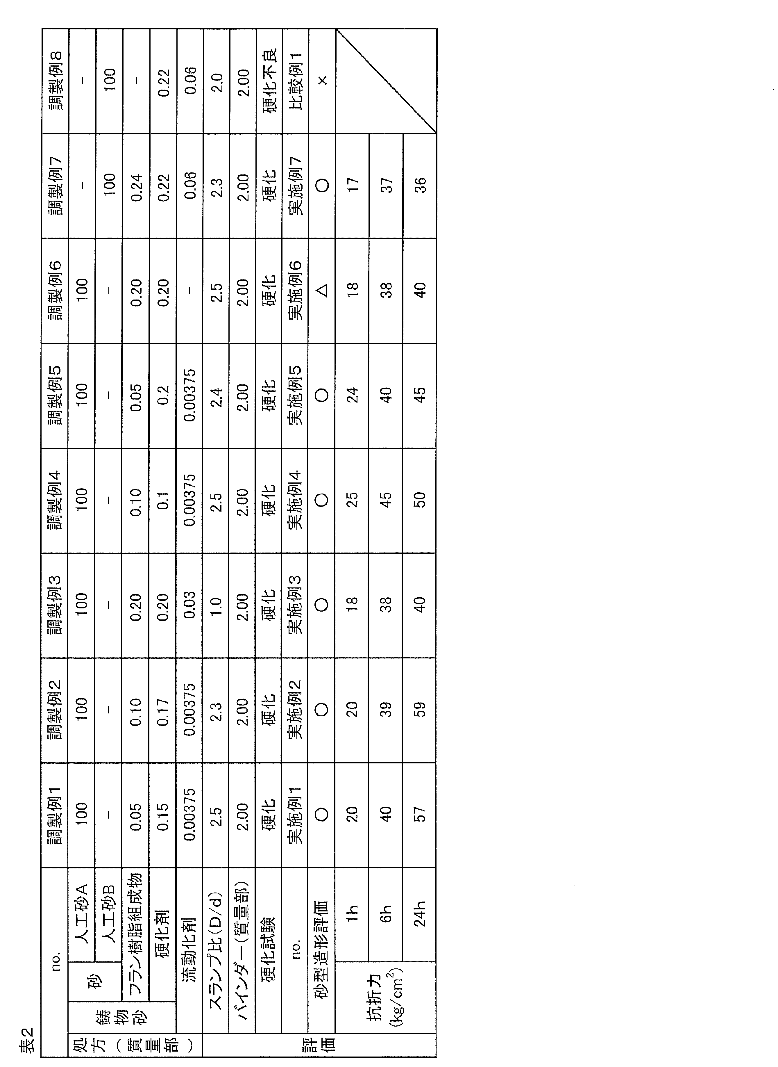
なお、調製例1〜8について、鋳物砂の処方を表2に示す。 In addition, about preparation examples 1-8, prescription of foundry sand is shown in Table 2.
調製例2
フラン樹脂組成物の添加量を0.10質量部に変更したこと、および、硬化剤の添加量を0.17質量部に変更したこと以外は、調製例1と同様にして、鋳物砂を調製した。
Preparation Example 2
Casting sand was prepared in the same manner as in Preparation Example 1, except that the addition amount of the furan resin composition was changed to 0.10 parts by mass and the addition amount of the curing agent was changed to 0.17 parts by mass. did.
調製例3
フラン樹脂組成物の添加量を0.20質量部に変更したこと、硬化剤の添加量を0.20質量部に変更したこと、および、リノール酸の添加量を0.03質量部に変更したこと以外は、調製例1と同様にして、鋳物砂を調製した。
Preparation Example 3
The addition amount of the furan resin composition was changed to 0.20 parts by mass, the addition amount of the curing agent was changed to 0.20 parts by mass, and the addition amount of linoleic acid was changed to 0.03 parts by mass. Except for this, casting sand was prepared in the same manner as in Preparation Example 1.
調製例4
フラン樹脂組成物の添加量を0.10質量部に変更したこと以外は、調製例1と同様にして、鋳物砂を調製した。
Preparation Example 4
Foundry sand was prepared in the same manner as in Preparation Example 1 except that the addition amount of the furan resin composition was changed to 0.10 parts by mass.
調製例5
硬化剤の添加量を0.20質量部に変更したこと以外は、調製例1と同様にして、鋳物砂を調製した。
Preparation Example 5
Foundry sand was prepared in the same manner as in Preparation Example 1 except that the addition amount of the curing agent was changed to 0.20 parts by mass.
調製例6
リノール酸を添加しなかったこと以外は、調製例3と同様にして、鋳物砂を調製した。
Preparation Example 6
Foundry sand was prepared in the same manner as Preparation Example 3 except that linoleic acid was not added.
調製例7
人工砂Aを人工砂B(ムライト砂、商品名:セラビーズ#550、伊藤忠セラテック社製)に変更したこと、フラン樹脂組成物の添加量を0.24質量部に変更したこと、硬化剤の添加量を0.22質量部に変更したこと、および、リノール酸の添加量を0.06質量部に変更したこと以外は、調製例1と同様にして、鋳物砂を調製した。
Preparation Example 7
Artificial sand A was changed to artificial sand B (mullite sand, trade name: Cerabeads # 550, manufactured by ITOCHU CERATECH), the addition amount of the furan resin composition was changed to 0.24 parts by mass, addition of a curing agent Foundry sand was prepared in the same manner as in Preparation Example 1 except that the amount was changed to 0.22 parts by mass and the addition amount of linoleic acid was changed to 0.06 parts by mass.
なお、人工砂Bの粒子径(単一粒子径)の範囲は、75μm〜425μm(モード径:212μm、AFS粒度指数:56.1)であり、人工砂Bは、カリ長石およびソーダ長石を含有していた。 The particle size (single particle size) of the artificial sand B is 75 μm to 425 μm (mode diameter: 212 μm, AFS particle size index: 56.1), and the artificial sand B contains potassium feldspar and soda feldspar. Was.
調製例8
フラン樹脂組成物を添加しなかったこと以外は、調製例7と同様にして、鋳物砂を調製した。つまり、鋳物砂は、人工砂Bを被覆する表面改質層を備えておらず、硬化剤が人工砂Bの表面に付着していた。
<硬化試験>
各調製例で得られた鋳物砂100質量部に、表1に示すバインダーを、表2に示す割合で添加した。
Preparation Example 8
Foundry sand was prepared in the same manner as in Preparation Example 7 except that the furan resin composition was not added. That is, the foundry sand was not provided with a surface modification layer for covering the artificial sand B, and the curing agent was adhered to the surface of the artificial sand B.
<Curing test>
The binder shown in Table 1 was added in a proportion shown in Table 2 to 100 parts by mass of the foundry sand obtained in each Preparation Example.
調製例1〜7の鋳物砂では、バインダーが硬化し、良好に固まった一方、調製例8の鋳物砂では、バインダーが十分に硬化せず、粘土状となった。その結果を表2に示す。
<スランプ試験>
特開2013−240799号公報に記載の方法に準拠して、スランプコーンの直径(d)に対する、スランプの直径(D)を測定した。
In the foundry sands of Preparation Examples 1 to 7, the binder was hardened and hardened well, whereas in the foundry sand of Preparation Example 8, the binder was not sufficiently cured and became a clay. The results are shown in Table 2.
<Slump test>
The diameter (D) of the slump with respect to the diameter (d) of the slump cone was measured according to the method described in JP2013-240799A.
具体的には、開口部の直径(スランプコーンの直径)が50mm、底面部の直径が50mm、高さが100mmのスランプコーンを準備し、そのスランプコーンに、各調製例で得た鋳物砂を詰めて、開口部が下となるように、定板上に配置した。 Specifically, a slump cone having an opening diameter (slump cone diameter) of 50 mm, a bottom surface diameter of 50 mm, and a height of 100 mm was prepared, and the foundry sand obtained in each of the preparation examples was added to the slump cone. Packed and placed on a plate so that the opening is on the bottom.
そして、スランプコーンを定板から垂直に引き上げ、鋳物砂の広がり直径(スランプフロー)をフランプの直径とし、スランプコーンの直径(d)に対する、スランプの直径(D)の比(D/d)を算出した。その結果を表2に示す。 Then, the slump cone is lifted vertically from the surface plate, the spread diameter of the foundry sand (slump flow) is defined as the flump diameter, and the ratio (D / d) of the slump diameter (D) to the slump cone diameter (d) is determined. Calculated. The results are shown in Table 2.
実施例1〜7および比較例1
調製例1〜8で得られた鋳物砂と、表1に示すバインダーとを、3次元積層造形装置(商品名:S−Print、ExOne社製)にセットし、リコータによる鋳物砂の層形成、および、ジェットヘッドによるバインダーの添加を順次繰り返して、バインダーの添加部分を積層して、砂型を調製した。
Examples 1-7 and Comparative Example 1
The foundry sand obtained in Preparation Examples 1 to 8 and the binder shown in Table 1 were set in a three-dimensional additive manufacturing apparatus (trade name: S-Print, manufactured by ExOne), and the foundry sand was layered by a recoater. And the addition of the binder by a jet head was repeated sequentially, and the added portion of the binder was laminated to prepare a sand mold.
砂型造形を、下記の基準により評価した。 Sand mold modeling was evaluated according to the following criteria.
○:3D−CADデータ通り、砂型が作製された。 ◯: A sand mold was produced according to 3D-CAD data.
△:砂型の一部に、3D−CADデータからのズレが生じた。 Δ: Deviation from 3D-CAD data occurred in part of the sand mold.
×:バインダーが硬化せず、砂型を造形できなかった。 X: The binder was not cured and the sand mold could not be formed.
その結果を表2に示す。
<抗折力試験>
図3Aに示すように、実施例1〜7および比較例1と同様にして、調製例1〜8で得られた鋳物砂を用いて、一辺Dが22.4mm、長さLが147mmである正四角柱の試験柱を調製した。
The results are shown in Table 2.
<Bending strength test>
As shown in FIG. 3A, in the same manner as in Examples 1 to 7 and Comparative Example 1, using the foundry sand obtained in Preparation Examples 1 to 8, the side D is 22.4 mm and the length L is 147 mm. A regular square column test column was prepared.
その試験柱を、室温24℃、湿度45%の条件下で、表2に示す各時間放置した。 The test column was allowed to stand for each time shown in Table 2 under conditions of a room temperature of 24 ° C. and a humidity of 45%.
そして、図3Bに示すように、試験柱を、試験柱の長さ方向外側から挟み込むように、試験装置(Universal Strength Machine PFG、シンプソン社製)にセットした。 Then, as shown in FIG. 3B, the test column was set in a test apparatus (Universal Strength Machine PFG, manufactured by Simpson) so as to be sandwiched from the outside in the length direction of the test column.
次いで、試験柱の一端を固定して、試験柱に対して他方側から、試験柱の長さ方向に沿って、試験柱に圧力を加えた。そして、試験柱が折れたときの圧力を抗折力とした。 Next, one end of the test column was fixed, and pressure was applied to the test column along the length direction of the test column from the other side with respect to the test column. And the pressure when a test pillar broke was made into the bending strength.
その結果を、表2に示す。 The results are shown in Table 2.
1 鋳物砂
2 砂
3 表面改質層
25 第1鋳物砂層
26 第1添加部分
27 第2鋳物砂層
28 第2添加部分
30 砂型
DESCRIPTION OF
Claims (4)
前記鋳物砂を層状に形成し、前記鋳物砂の層にバインダーを添加して、前記鋳物砂の層における前記バインダーの添加部分を固める固化工程と、
前記固化工程を繰り返して、前記添加部分を積層する積層工程と、を含むことを特徴とする、砂型の製造方法。 A preparatory step for preparing foundry sand having sand and a surface-modified layer containing a cured resin that covers the sand, and comprising a curing agent attached to the surface-modified layer;
Forming the foundry sand into layers, adding a binder to the foundry sand layer, and solidifying the added portion of the binder in the foundry sand layer; and
And a laminating step of laminating the added portion by repeating the solidification step.
前記バインダーは、フラン樹脂前駆体を含有していることを特徴とする、請求項1に記載の砂型の製造方法。 The cured resin is a furan resin,
The said binder contains the furan resin precursor, The manufacturing method of the sand type | mold of Claim 1 characterized by the above-mentioned.
Priority Applications (1)
| Application Number | Priority Date | Filing Date | Title |
|---|---|---|---|
| JP2015236136A JP6868333B2 (en) | 2015-12-02 | 2015-12-02 | Sand mold manufacturing method and sand mold |
Applications Claiming Priority (1)
| Application Number | Priority Date | Filing Date | Title |
|---|---|---|---|
| JP2015236136A JP6868333B2 (en) | 2015-12-02 | 2015-12-02 | Sand mold manufacturing method and sand mold |
Publications (2)
| Publication Number | Publication Date |
|---|---|
| JP2017100162A true JP2017100162A (en) | 2017-06-08 |
| JP6868333B2 JP6868333B2 (en) | 2021-05-12 |
Family
ID=59017845
Family Applications (1)
| Application Number | Title | Priority Date | Filing Date |
|---|---|---|---|
| JP2015236136A Active JP6868333B2 (en) | 2015-12-02 | 2015-12-02 | Sand mold manufacturing method and sand mold |
Country Status (1)
| Country | Link |
|---|---|
| JP (1) | JP6868333B2 (en) |
Cited By (3)
| Publication number | Priority date | Publication date | Assignee | Title |
|---|---|---|---|---|
| JP2020104125A (en) * | 2018-12-26 | 2020-07-09 | 伊藤忠セラテック株式会社 | Reclamation sand regeneration process |
| WO2021254953A1 (en) * | 2020-06-15 | 2021-12-23 | Ask Chemicals Gmbh | Method for the layer-by-layer production of a cured three-dimensional shaped body, shaped body obtainable by the method, and use thereof |
| JP2022071870A (en) * | 2020-10-28 | 2022-05-16 | 株式会社清田鋳機 | Casting sand for lamination molding and method for producing the same |
Citations (6)
| Publication number | Priority date | Publication date | Assignee | Title |
|---|---|---|---|---|
| JPS62142048A (en) * | 1985-12-13 | 1987-06-25 | Asahi Organic Chem Ind Co Ltd | Production of acid curing type organic self-curing sand |
| JPH03134067A (en) * | 1989-10-10 | 1991-06-07 | Acme Resin Corp | Method for improving flowability of sand coated with alkaline phenol resin |
| JP2012061517A (en) * | 2010-09-17 | 2012-03-29 | Kao Corp | Composition for self-curing mold |
| JP2013240799A (en) * | 2012-05-17 | 2013-12-05 | Kimura Chuzosho:Kk | Molding sand for three-dimensional laminating shape |
| JP5429516B2 (en) * | 2008-07-01 | 2014-02-26 | 日立化成株式会社 | Furan resin composition for mold production and use thereof |
| JP6027263B1 (en) * | 2015-03-09 | 2016-11-16 | 技術研究組合次世代3D積層造形技術総合開発機構 | Organic binder, granular material, three-dimensional additive manufacturing mold manufacturing apparatus, and three-dimensional additive manufacturing mold manufacturing method |
-
2015
- 2015-12-02 JP JP2015236136A patent/JP6868333B2/en active Active
Patent Citations (6)
| Publication number | Priority date | Publication date | Assignee | Title |
|---|---|---|---|---|
| JPS62142048A (en) * | 1985-12-13 | 1987-06-25 | Asahi Organic Chem Ind Co Ltd | Production of acid curing type organic self-curing sand |
| JPH03134067A (en) * | 1989-10-10 | 1991-06-07 | Acme Resin Corp | Method for improving flowability of sand coated with alkaline phenol resin |
| JP5429516B2 (en) * | 2008-07-01 | 2014-02-26 | 日立化成株式会社 | Furan resin composition for mold production and use thereof |
| JP2012061517A (en) * | 2010-09-17 | 2012-03-29 | Kao Corp | Composition for self-curing mold |
| JP2013240799A (en) * | 2012-05-17 | 2013-12-05 | Kimura Chuzosho:Kk | Molding sand for three-dimensional laminating shape |
| JP6027263B1 (en) * | 2015-03-09 | 2016-11-16 | 技術研究組合次世代3D積層造形技術総合開発機構 | Organic binder, granular material, three-dimensional additive manufacturing mold manufacturing apparatus, and three-dimensional additive manufacturing mold manufacturing method |
Non-Patent Citations (3)
| Title |
|---|
| 硬化触媒ガイド, JPN6020020989, August 1979 (1979-08-01), pages 1 - 3, ISSN: 0004287613 * |
| 鋳砂再生法とその実例集, JPN6020020988, July 1979 (1979-07-01), pages 7 - 8, ISSN: 0004287611 * |
| 鋳鉄工場への人工砂導入のための指針と事例, JPN6020020986, 18 May 2012 (2012-05-18), JP, pages 79 - 82, ISSN: 0004287612 * |
Cited By (5)
| Publication number | Priority date | Publication date | Assignee | Title |
|---|---|---|---|---|
| JP2020104125A (en) * | 2018-12-26 | 2020-07-09 | 伊藤忠セラテック株式会社 | Reclamation sand regeneration process |
| JP7142563B2 (en) | 2018-12-26 | 2022-09-27 | 伊藤忠セラテック株式会社 | How to recycle recovered sand |
| WO2021254953A1 (en) * | 2020-06-15 | 2021-12-23 | Ask Chemicals Gmbh | Method for the layer-by-layer production of a cured three-dimensional shaped body, shaped body obtainable by the method, and use thereof |
| JP2022071870A (en) * | 2020-10-28 | 2022-05-16 | 株式会社清田鋳機 | Casting sand for lamination molding and method for producing the same |
| JP7101392B2 (en) | 2020-10-28 | 2022-07-15 | 株式会社清田鋳機 | Casting sand for laminated molding and its manufacturing method |
Also Published As
| Publication number | Publication date |
|---|---|
| JP6868333B2 (en) | 2021-05-12 |
Similar Documents
| Publication | Publication Date | Title |
|---|---|---|
| WO2018159616A1 (en) | Method for producing casting sand, and casting sand | |
| JP6027263B1 (en) | Organic binder, granular material, three-dimensional additive manufacturing mold manufacturing apparatus, and three-dimensional additive manufacturing mold manufacturing method | |
| JP6289648B1 (en) | Granular material, method for producing granular material, and method for producing three-dimensional additive manufacturing mold | |
| WO2013171921A1 (en) | Molding sand for rapid prototyping | |
| US7951454B2 (en) | Resin-coated sand | |
| KR20170010779A (en) | Method for the Layer-Wise Building of Bodies Comprising Refractory Mold Base Material and Resoles, and Molds or Cores Manufactured According to Said Method | |
| JP5867939B1 (en) | Material for additive manufacturing, method for producing mold by powder fixed lamination method, and mold | |
| JP6470542B2 (en) | Molding method of laminated mold | |
| JP6096378B1 (en) | Manufacturing method of granular material for manufacturing 3D additive manufacturing mold and manufacturing method of 3D additive manufacturing mold | |
| MX2012006582A (en) | Foundry mixes containing carbonate salts and their uses. | |
| JP6027264B1 (en) | Granular material, three-dimensional additive manufacturing mold manufacturing apparatus, and three-dimensional additive manufacturing mold manufacturing method | |
| JP6868333B2 (en) | Sand mold manufacturing method and sand mold | |
| JP2015193035A (en) | Method of manufacturing three-dimensional laminated formed object | |
| JP6868334B2 (en) | Casting sand | |
| JP7175822B2 (en) | Sand composition, method for producing same, and method for producing mold | |
| CN110586848A (en) | Sand mold material for 3D printing cast steel, preparation method thereof and method for manufacturing cast steel sand mold by using material | |
| Nagai et al. | Molding and mold properties of spherical artificial sand coated with inorganic binder | |
| US7659327B2 (en) | Coated microspheres and their use | |
| JP6767899B2 (en) | Manufacturing method of recycled sand and manufacturing method of foundry sand | |
| JP7240655B2 (en) | Materials for 3D additive manufacturing | |
| JPH0339774B2 (en) | ||
| JP7046752B2 (en) | Sand composition and its manufacturing method, and manufacturing method of three-dimensional laminated molding mold | |
| JP7202238B2 (en) | Coated sand and mold manufacturing method using the same | |
| WO2016075845A1 (en) | Material for lamination molding, production method for mold using powder fixing lamination method, and mold |
Legal Events
| Date | Code | Title | Description |
|---|---|---|---|
| A621 | Written request for application examination |
Free format text: JAPANESE INTERMEDIATE CODE: A621 Effective date: 20181105 |
|
| A711 | Notification of change in applicant |
Free format text: JAPANESE INTERMEDIATE CODE: A711 Effective date: 20190724 |
|
| A521 | Request for written amendment filed |
Free format text: JAPANESE INTERMEDIATE CODE: A821 Effective date: 20190724 |
|
| A977 | Report on retrieval |
Free format text: JAPANESE INTERMEDIATE CODE: A971007 Effective date: 20190828 |
|
| A131 | Notification of reasons for refusal |
Free format text: JAPANESE INTERMEDIATE CODE: A131 Effective date: 20190903 |
|
| A601 | Written request for extension of time |
Free format text: JAPANESE INTERMEDIATE CODE: A601 Effective date: 20191101 |
|
| A521 | Request for written amendment filed |
Free format text: JAPANESE INTERMEDIATE CODE: A523 Effective date: 20191224 |
|
| A131 | Notification of reasons for refusal |
Free format text: JAPANESE INTERMEDIATE CODE: A131 Effective date: 20200623 |
|
| A601 | Written request for extension of time |
Free format text: JAPANESE INTERMEDIATE CODE: A601 Effective date: 20200721 |
|
| A521 | Request for written amendment filed |
Free format text: JAPANESE INTERMEDIATE CODE: A523 Effective date: 20201019 |
|
| TRDD | Decision of grant or rejection written | ||
| A01 | Written decision to grant a patent or to grant a registration (utility model) |
Free format text: JAPANESE INTERMEDIATE CODE: A01 Effective date: 20210330 |
|
| A61 | First payment of annual fees (during grant procedure) |
Free format text: JAPANESE INTERMEDIATE CODE: A61 Effective date: 20210412 |
|
| R150 | Certificate of patent or registration of utility model |
Ref document number: 6868333 Country of ref document: JP Free format text: JAPANESE INTERMEDIATE CODE: R150 |
|
| R250 | Receipt of annual fees |
Free format text: JAPANESE INTERMEDIATE CODE: R250 |