JP2017097537A - Guiding robot - Google Patents
Guiding robot Download PDFInfo
- Publication number
- JP2017097537A JP2017097537A JP2015227613A JP2015227613A JP2017097537A JP 2017097537 A JP2017097537 A JP 2017097537A JP 2015227613 A JP2015227613 A JP 2015227613A JP 2015227613 A JP2015227613 A JP 2015227613A JP 2017097537 A JP2017097537 A JP 2017097537A
- Authority
- JP
- Japan
- Prior art keywords
- destination
- unit
- display
- image
- information
- Prior art date
- Legal status (The legal status is an assumption and is not a legal conclusion. Google has not performed a legal analysis and makes no representation as to the accuracy of the status listed.)
- Pending
Links
- 238000001514 detection method Methods 0.000 claims description 42
- 238000000034 method Methods 0.000 description 51
- 230000008569 process Effects 0.000 description 37
- 238000012545 processing Methods 0.000 description 18
- 238000012937 correction Methods 0.000 description 17
- 238000004364 calculation method Methods 0.000 description 15
- 239000003550 marker Substances 0.000 description 13
- 238000010586 diagram Methods 0.000 description 8
- 239000002245 particle Substances 0.000 description 7
- 230000004044 response Effects 0.000 description 7
- 238000013130 cardiovascular surgery Methods 0.000 description 5
- 230000008859 change Effects 0.000 description 5
- 230000000172 allergic effect Effects 0.000 description 4
- 208000010668 atopic eczema Diseases 0.000 description 4
- 210000004556 brain Anatomy 0.000 description 3
- 238000005259 measurement Methods 0.000 description 3
- 238000001356 surgical procedure Methods 0.000 description 3
- 238000013459 approach Methods 0.000 description 2
- 230000001174 ascending effect Effects 0.000 description 2
- 239000003814 drug Substances 0.000 description 2
- 230000000694 effects Effects 0.000 description 2
- 206010020751 Hypersensitivity Diseases 0.000 description 1
- 208000026935 allergic disease Diseases 0.000 description 1
- 230000007815 allergy Effects 0.000 description 1
- 229940079593 drug Drugs 0.000 description 1
- 238000005516 engineering process Methods 0.000 description 1
- 238000002474 experimental method Methods 0.000 description 1
- 230000006870 function Effects 0.000 description 1
- 210000003127 knee Anatomy 0.000 description 1
- 239000004973 liquid crystal related substance Substances 0.000 description 1
- 239000000463 material Substances 0.000 description 1
- 238000012986 modification Methods 0.000 description 1
- 230000004048 modification Effects 0.000 description 1
- 230000003287 optical effect Effects 0.000 description 1
- 230000002093 peripheral effect Effects 0.000 description 1
- 230000002265 prevention Effects 0.000 description 1
- 230000000241 respiratory effect Effects 0.000 description 1
- 239000010979 ruby Substances 0.000 description 1
- 229910001750 ruby Inorganic materials 0.000 description 1
Images


Abstract
Description
本発明は、被案内者を目的地まで案内する案内用ロボットに関する。 The present invention relates to a guidance robot for guiding a guided person to a destination.
従来、被案内者をロボットによって目的地まで案内する技術として、例えば、特許文献1に記載された技術がある。この技術は、被案内者がタッチパネルを介して案内先を入力し、ロボットは入力された案内先に従って案内を行うものである。
Conventionally, as a technique for guiding a guided person to a destination by a robot, for example, there is a technique described in
しかしながら、上記特許文献1の従来技術は、タッチパネル(モニタ)に、具体的にどのような入力画面を表示するのかについては記載がない。そのため、例えばソフトウェアキーボードによって案内先(目的地)の名称を入力するような入力画面などの被案内者に複雑な入力操作(手間のかかる操作)を要求する入力画面が表示される場合に、案内先の設定時間が長くなるといった問題が生じる恐れがある。
そこで、本発明は、このような従来の技術の有する未解決の課題に着目してなされたものであって、被案内者が目的地の設定を簡易な操作で行うことが可能な案内用ロボットを提供することを課題としている。
However, the prior art of
Therefore, the present invention has been made paying attention to such an unsolved problem of the conventional technology, and a guide robot that allows a guided person to set a destination by a simple operation. It is an issue to provide.
上記目的を達成するために、本発明の一実施形態に係る案内用ロボットは、アクチュエータから付与される駆動力によって任意の方向に移動可能な移動体と、前記移動体に取り付けられ、画像を表示する表示部と前記被案内者が前記表示部の表示面をタッチしたときのタッチ位置を検出するタッチ位置検出部とを備えた表示入力部と、前記表示部に、前記被案内者の案内先となる複数の目的地候補の情報を示す画像である目的地候補画像を表示する目的地候補画像表示部と、前記表示部に前記目的地候補画像が表示されているときの前記タッチ位置の情報に基づき、前記複数の目的地候補のうちからタッチ位置に対応する目的地候補を選択し、選択した目的地候補を目的地として設定する目的地設定部と、前記移動体が移動するエリアの地図情報が格納された地図情報格納部と、前記移動体の現在位置を推定する自己位置推定部と、前記地図情報に基づき、前記自己位置推定部で推定した現在位置から前記目的地設定部で設定した目的地までの前記移動体の移動経路を生成する経路生成部と、前記自己位置推定部で推定した現在位置と前記経路生成部で生成した移動経路とに基づき、前記移動体の目標進行方向を決定する目標進行方向決定部と、前記目標進行方向決定部で決定した目標進行方向に基づき、前記アクチュエータを駆動制御して前記移動体の移動を制御する移動制御部と、を備える。 In order to achieve the above object, a guidance robot according to an embodiment of the present invention is a movable body that is movable in an arbitrary direction by a driving force applied from an actuator, and is attached to the movable body and displays an image. A display input unit provided with a display unit that performs a touch and a touch position detection unit that detects a touch position when the guided person touches the display surface of the display unit; A destination candidate image display unit that displays a destination candidate image that is an image indicating information of a plurality of destination candidates, and information on the touch position when the destination candidate image is displayed on the display unit A destination setting unit that selects a destination candidate corresponding to the touch position from the plurality of destination candidates, and sets the selected destination candidate as a destination, and a map of an area in which the moving body moves Set in the destination setting unit from the current position estimated by the self-position estimation unit based on the map information based on the map information, the map information storage unit storing the information, the self-position estimation unit estimating the current position of the mobile body A target travel direction of the mobile body based on the path generation unit that generates the travel path of the mobile body to the destination and the current position estimated by the self-position estimation unit and the travel path generated by the path generation unit And a movement control unit that controls the movement of the moving body by driving the actuator based on the target traveling direction determined by the target traveling direction determination unit.
本発明によれば、複数の目的地候補の情報を示す目的地候補画像を表示部に表示し、目的地候補画像の表示中に表示部の表示面を被案内者がタッチすることで、タッチ位置に対応する目的地候補を選択し、選択した目的地候補を目的地として設定することが可能となる。これによって、複数の目的地候補が表示されている表示面における所望の目的地候補の表示位置をタッチするといった簡易な操作で目的地の設定を行うようにすることが可能となり、例えば目的地の名称を入力するといった比較的複雑な操作を要する場合と比較して目的地の設定にかかる時間を低減することが可能となる。その結果、案内用ロボットが1人の被案内者によって占有される時間を短縮することが可能となり、案内用ロボットの稼動効率を向上することが可能となる。また、環境側に変更があっても目的地を選択するスイッチ等を追加することなくソフトウェアの変更によって簡易に対応することが可能となる。 According to the present invention, a destination candidate image indicating information of a plurality of destination candidates is displayed on the display unit, and the guide person touches the display surface of the display unit while the destination candidate image is being displayed. A destination candidate corresponding to the position can be selected, and the selected destination candidate can be set as the destination. This makes it possible to set the destination by a simple operation such as touching the display position of the desired destination candidate on the display surface on which a plurality of destination candidates are displayed. Compared with the case where a relatively complicated operation such as inputting a name is required, the time required for setting the destination can be reduced. As a result, it is possible to shorten the time for which the guidance robot is occupied by one guided person, and it is possible to improve the operation efficiency of the guidance robot. Further, even if there is a change on the environment side, it is possible to easily cope with the change of software without adding a switch or the like for selecting the destination.
次に、図面に基づき、本発明の実施形態を説明する。以下の図面の記載において、同一又は類似の部分には同一又は類似の符号を付している。ただし、図面は模式的なものであり、寸法の関係や比率等は現実のものとは異なることに留意すべきである。
また、以下に示す実施形態は、本発明の技術的思想を具体化するための装置や方法を例示するものであって、本発明の技術的思想は、構成部品の材質、形状、構造、配置等を下記のものに特定するものでない。本発明の技術的思想は、特許請求の範囲に記載された請求項が規定する技術的範囲内において、種々の変更を加えることができる。
Next, embodiments of the present invention will be described with reference to the drawings. In the following description of the drawings, the same or similar parts are denoted by the same or similar reference numerals. However, it should be noted that the drawings are schematic and dimensional relationships and ratios are different from actual ones.
Further, the following embodiments exemplify apparatuses and methods for embodying the technical idea of the present invention, and the technical idea of the present invention is the material, shape, structure, and arrangement of components. Etc. are not specified below. The technical idea of the present invention can be variously modified within the technical scope defined by the claims described in the claims.
(構成)
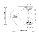
本実施形態に係る案内用ロボット1は、図1〜図2に示すように、車輪による走行によって任意の方向に移動する移動体2を有する。この移動体2は、底面から見て前端部が尖った流線形状に形成され、且つ例えば案内用ロボット1に案内される被案内者の膝程度の高さを有する基台3を備えている。この基台3は、その上面に荷台部4を備え、荷台部4の両側端部及び後端部に沿って荷台部4上に載せた荷物の落下を防止するための落下防止柵13が形成されている。加えて、基台3は、その後端部側の幅が被案内者の肩幅以下になるよう形成されている。
なお、図1〜図2に示すように、移動体2の上下方向に延びる軸をZ軸とし、移動体2の前後方向に延びる軸をY軸とし、移動体2の左右方向に延びる軸をX軸とする。
(Constitution)
As shown in FIGS. 1 to 2, the
As shown in FIGS. 1 to 2, the axis extending in the vertical direction of the
基台3の底面には、前端側にキャスター5が旋回自在に配置され、後方端側の左右位置に駆動輪(車輪)6L及び6Rが回転自在に支持されている。これら駆動輪6L及び6Rの夫々は、車軸7L及び7Rの内側にプーリ8L及び8Rが固定されている。
そして、これらプーリ8L及び8Rと、各駆動輪6L及び6Rの前方側に配置した第1及び第2電動モータ9L及び9Rの回転軸に固定したプーリ10L及び10Rとの間に無端のタイミングベルト11L及び11Rが巻回されて、第1及び第2電動モータ9L及び9Rの回転軸の回転速度と同一回転速度で駆動輪6L及び6Rが回転駆動される。ここで、各第1及び第2電動モータ9L及び9Rには、ギアヘッド12L及び12Rが設けられている。
On the bottom surface of the
An
このとき、第1及び第2電動モータ9L及び9Rの回転軸の回転速度を等しくすると、回転軸の回転方向に応じて基台3が前後方向に移動し、左側の駆動輪6Lの回転速度を右側の駆動輪6Rの回転速度より遅い回転速度(又は速い回転速度)で駆動すると基台3が左旋回(又は右旋回)する。
また、左側の駆動輪6L(又は右側の駆動輪6R)を停止させた状態で、右側の駆動輪6R(又は左側の駆動輪6L)を正回転駆動すると信地左(又は右)旋回状態となる。
さらに、左側の駆動輪6L(又は右側の駆動輪6R)を逆回転駆動し、右側の駆動輪6R(又は左側の駆動輪6L)を正回転駆動する超信地左(又は右)旋回状態となる。
At this time, if the rotation speeds of the rotation shafts of the first and second
In addition, when the right
Further, the left
このように、左右の駆動輪6L及び6Rの回転速度を制御することにより、基台3を任意の方向に走行させることができる。
基台3には、その上面における前端側から上方側に延長する支持腕15が固定されている。この支持腕15の上端部には、基台3と平行かつ後方に基台3の後端部の近傍位置まで延長する水平腕16が形成されている。
この水平腕16の上面における後端側には、被案内者が把持すると共に前後進速度を入力する操作入力部17が配置されている。操作入力部17は、被案内者が一方の手指で把持することが可能なグリップ18と、このグリップ18を連結支持して、グリップ18に加えられた互いに交差する二軸方向の力をそれぞれ検出する力センサ19とを備える。本実施形態では、二軸の一方を、図1及び図2に示す移動体2の前後方向に延びるY軸とし、二軸の他方を、図1に示す支持腕15に沿った方向(グリップ18を力センサ19に向かって押し下げる方向)に延びる軸(以下、「Z'軸」と称す)とした場合について説明する。
Thus, the
A
On the rear end side of the upper surface of the
即ち、力センサ19は、グリップ18に加えられたY軸方向の力Fy及びZ'軸方向の力Fz'を検出するように構成されている。
なお、力センサ19は、Y軸及びZ'軸方向の力を検出する構成に限らず、図2に示す移動体2の左右方向に延びるX軸回りのモーメントMxと、Z'軸方向の力Fz'とを検出する構成としてもよい。
また、水平腕16の上面における中央部には、被案内者が目的地の選択や経路の確認等をするための表示入力装置であるタッチパネルディスプレイ20が配置されている。
That is, the
The
In addition, a
タッチパネルディスプレイ20は、液晶ディスプレイの表示パネル部に、タッチ位置を検出するタッチパネルを組み込んだ表示装置である。
タッチパネルディスプレイ20は、タッチパネルの位置検出方式に応じて、静電容量方式、超音波方式、抵抗膜方式、光学方式等の種類がある。
タッチパネルディスプレイ20は、後述する演算処理装置31からの指令に応じて各種画像の表示を行うと共に、被案内者が表示パネル部の表示面(タッチ面)をタッチすることによってタッチパネルを介して検出されたタッチ位置情報を後述するタッチ位置入力I/F66を介して演算処理装置31に入力する。
The
The
The
これにより、被案内者は、例えば、タッチパネルディスプレイ20の表示パネル部に表示されたボタンや文字等の画像の表示位置をタッチすることで各種指示入力を行うことが可能となる。
基台3の先端側の側面には、例えば300度の角度範囲に渡って帯状の開口部21が形成されている。そして、この開口部21の先端部に対応する内側には、スキャナ式レンジセンサから構成される第1障害物検出センサ22が設けられている。この第1障害物検出センサ22は、水平方向に後方側の90度の角度範囲を除く270度の角度範囲でレーザ光を使用して、下方(床上)にある障害物(以下、下方障害物という)までの距離を計測するものである。
Accordingly, the guided person can input various instructions by touching the display positions of images such as buttons and characters displayed on the display panel unit of the
On the side surface on the front end side of the
また、水平腕16の前端側には、位置測位センサ23が設けられている。この位置測位センサ23は、天井に設置されたマーカ(以下、「天井マーカ」という)を読み取るためのセンサである。本実施形態では、交差点、エレベータホール、階段の手前等の施設の要所には天井に予め天井マーカを設置してあり、位置測位センサ23は、前方上方に向けたカメラによって天井マーカを読み取るようになっている。
また、支持腕15の上端側における裏面側には、スキャナ式レンジセンサから構成される第2障害物検出センサ24が設けられている。この第2障害物検出センサ24は、例えば上方側の120度の角度範囲を除く240度の角度範囲で斜め下側の障害物までの距離を計測するものである。
さらに、案内用ロボット1の中央部付近である支持腕15の下端部の前面側には、距離画像センサから構成される上方障害物センサ25が設けられている。この上方障害物センサ25は、赤外線レーザによって前方且つ上方の空間に特定のパターンを投影し、それをカメラで撮影して対象物の位置と距離とを測定する、所謂デプスカメラである。上方障害物センサ25は、案内用ロボット1の前方且つ上方にある障害物(以下、上方障害物という)を検出する。
A
A second
Further, an
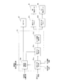
第1及び第2電動モータ9L及び9Rは、図3に示すように、走行制御装置30によって、駆動制御される。
この走行制御装置30は、図3に示すように、移動体2に内蔵するバッテリによって駆動される、例えばマイクロコントローラ等の演算処理装置31を備えている。演算処理装置31は、走行制御部51と、目的地案内部52と、センサ信号入力I/F53と、速度指令値出力I/F54と、回転角度位置入力I/F55と、画像出力I/F56と、タッチ位置入力I/F57と、音声出力I/F58と、を備える。
センサ信号入力I/F53には、操作入力部17の力センサ19と、各第1及び第2障害物検出センサ22及び24と、位置測位センサ23と、上方障害物センサ25とが接続されている。そして、センサ信号入力I/F53は、力センサ19から出力されるY,Z'軸の2軸方向に付与される力Fy及びFz'を読込む。また、センサ信号入力I/F53は、第1及び第2障害物検出センサ22及び24から出力される障害物位置情報と、位置測位センサ23から出力される天井マーカ位置情報と、上方障害物センサ25から出力される障害物位置情報とを読込む。センサ信号入力I/F53は、読込んだ各種情報を走行制御部51へ出力する。
The first and second
As shown in FIG. 3, the
The sensor signal input I /
速度指令値出力I/F54は、走行制御部51で生成した速度指令値を、第1及び第2モータドライバ61L及び61Rに出力する。ここで、第1及び第2モータドライバ61L及び61Rは、移動体2に内蔵するバッテリから電力が供給され、第1及び第2電動モータ9L及び9Rを駆動するためのものである。
回転角度位置入力I/F55は、第1及び第2電動モータ9L及び9Rの回転角度位置を検出する第1及び第2ロータリエンコーダ62L及び62Rから出力される回転角度位置情報を読込み、走行制御部51及び目的地案内部52へ出力する。
The speed command value output I /
The rotation angle position input I /
画像出力I/F56は、目的地案内部52で生成した目的地を決定するための各種画像(以下、「目的地決定用画像」と記載する場合がある)や、被案内者の現在位置周辺の地図、現在位置及び目的地までの経路情報等からなるナビゲーション画像などの画像情報をタッチパネルディスプレイ20に出力する。
タッチ位置入力I/F57は、タッチパネルディスプレイ20からのタッチ位置の位置情報(座標情報)を読込み、目的地案内部52へ出力する。
音声出力I/F58は、走行制御部51及び目的地案内部52で生成した音声案内情報をスピーカ67へ出力する。ここで、音声案内情報とは、被案内者が進むべき方向(目標進行方向)や、被案内者の現在位置の場所情報、障害物の接近を知らせる情報などを含むものである。
The image output I /
The touch position input I /
The voice output I /
(走行制御部51の構成)
以下、図4に基づき、走行制御部51について具体的に説明する。
走行制御部51は、図4に示すように、走行方向算出部51aと、障害物検出部51bと、走行方向補正部51cと、モータ駆動制御部51dとを備える。
この走行制御部51は、被案内者による操作入力部17の操作入力に基づいて第1及び第2電動モータ9L及び9Rに対する速度指令値を生成し、これを第1及び第2モータドライバ61L及び61Rに出力することで移動体2を走行制御するものである。また、走行制御部51は、移動体2の移動過程において、常時、周囲の障害物の有無を検出し、障害物を検出すると被案内者に障害物が接近していることを音声や警報で知らせると共に、移動体2の移動方向を、障害物を回避する方向に修正する障害物回避機能を有する。
(Configuration of traveling control unit 51)
Hereinafter, the
As shown in FIG. 4, the
The
先ず、走行方向算出部51aは、操作入力部17の力センサ19から出力される移動体2のY軸方向の力Fy及びZ'軸方向の力Fz'を、操作入力情報として読込む。加えて、目的地案内部52が出力する案内用ロボット1の現在位置の情報である自己位置情報及び走行経路情報を入力する。
次に、走行方向算出部51aは、Z'軸方向の力Fz'と予め設定した閾値とを比較することで、被案内者がグリップ18を押下したか否かを検出する。このとき、被案内者がグリップ18を押下していない(Fz'≦閾値)場合にはそのまま待機し、被案内者がグリップ18を押下すると(Fz'>閾値)、Y軸方向の力Fyに基づいて、移動体2の前後進方向の進行速度である前後進速度V0[m/s]及び旋回速度ω0[rad/s]を算出する。
First, the traveling
Next, the traveling
ここで、前後進速度V0は、移動体2の仮想質量をMとしたとき、例えば下式(1)に従って算出する。
V0=∫(Fy/M)dt …………(1)
更に、走行方向算出部51aは、自己位置情報と走行経路情報とに基づき、進行方向(旋回角度θ)を決定し、この旋回角度θと、実験等によって求めた旋回角度と旋回半径との関係とに基づき、旋回半径rを算出する。即ち、実験によって、安全性や快適性等を考慮して決定した旋回角度と旋回半径との関係(例えば、マップデータ)から、旋回半径rを算出(決定)する。
Here, the forward / reverse speed V0 is calculated according to the following equation (1), for example, where M is the virtual mass of the moving
V0 = ∫ (Fy / M) dt (1)
Further, the traveling
そして、前後進速度V0と、旋回半径rとから、下式(2)に従って旋回速度ω0を算出する。
ω0=r/V0 …………(2)
そして、走行方向算出部51aは、算出した前後進速度V0及び旋回速度ω0をRAM等に記憶すると共に、これらを障害物検出部51b及び走行方向補正部51cに出力する。
なお、前後進速度V0及び旋回速度ω0には、安全性を確保するためにそれぞれ上限速度Vmax及びωmaxが設定されており、算出後の前後進速度V0及び旋回速度ω0が上限速度Vmax及びωmaxを超えないように制限される。例えば、算出後の前後進速度V0及び旋回速度ω0が上限速度Vmax及びωmaxを超える場合、これら算出値を上限速度Vmax及びωmaxに変更する。
Then, the turning speed ω0 is calculated from the forward / reverse speed V0 and the turning radius r according to the following equation (2).
ω0 = r / V0 (2)
Then, the traveling
In order to ensure safety, upper and lower speeds Vmax and ωmax are set for the forward / reverse speed V0 and the turning speed ω0, respectively. Limited not to exceed. For example, when the calculated forward / reverse speed V0 and turning speed ω0 exceed the upper limit speeds Vmax and ωmax, these calculated values are changed to the upper limit speeds Vmax and ωmax.
障害物検出部51bは、障害物位置情報として、第1及び第2障害物検出センサ22及び24で測定したスキャン角度及び距離検出値を読込み、下方障害物の位置及び下方障害物までの距離を算出する。また、障害物検出部51bは、障害物位置情報として、上方障害物センサ25で撮影した画像データを読込み、上方障害物の位置及び上方障害物までの距離を算出する。ここで、障害物が複数存在する場合には、各障害物について位置及び障害物までの距離を算出する。
そして、障害物検出部51bは、走行方向算出部51aで記憶した前後進速度V0及び旋回速度ω0と、検出した障害物の位置及び距離とに基づいて、移動体2が下方障害物又は上方障害物に接触する可能性があるか否かを判定する。この判定結果は、走行方向補正部51cに出力される。
The
The
また、障害物検出部51bは、移動体2が障害物に接触する可能性があると判定すると、当該障害物への接触回避を目的として、被案内者に障害物が接近していることを知らせるための音声案内情報を生成し、その音声案内情報をもとにスピーカ67から音声を出力する。
また、障害物検出部51bは、障害物の検出位置の情報である障害物検出位置情報を目的地案内部52に出力する。
走行方向補正部51cは、障害物検出部51bで障害物に接触する可能性があると判定したとき、当該障害物を回避する方向に前後進速度V0及び旋回速度ω0を補正し、補正後の前後進速度V及び旋回速度ωをモータ駆動制御部51dに出力する。
When the
In addition, the
When the
また、走行方向補正部51cは、障害物検出部51bで障害物に接触する可能性はないと判定した場合には、前後進速度V0及び旋回速度ω0をそのまま前後進速度V及び旋回速度ωとしてモータ駆動制御部51dに出力する。
モータ駆動制御部51dは、前後進速度V及び旋回速度ωに基づいて、下式(3)及び(4)に従って、駆動輪6L及び6Rの車輪周速度VL〔m/s〕及びVR〔m/s〕を算出する。
VL=V+Lw・ω/2 …………(3)
VR=V−Lw・ω/2 …………(4)
When the
The motor
VL = V + Lw · ω / 2 (3)
VR = V−Lw · ω / 2 (4)
ここで、Lwは、左右の駆動輪6L及び6Rの車輪間距離〔m〕である。そして、モータ駆動制御部51dは、上記(3)及び(4)をもとに算出した駆動輪6L及び6Rの車輪周速度VL及びVRに基づいて、第1及び第2電動モータ9L及び9Rの速度指令値VML及びVMRを算出し、これらを速度指令値出力I/F54を介して第1及び第2モータドライバ61L及び61Rに出力する。
なお、ここでは、走行制御部51の障害物回避制御として、障害物との接触を回避する方向に移動体2の走行方向を修正する制御を行う場合について説明したが、障害物を検出したとき、移動体2の走行を停止することで障害物との接触を回避するようにしてもよい。
Here, Lw is the distance [m] between the left and
Here, as the obstacle avoidance control of the traveling
(目的地案内部52の構成)
次に、図5に基づき、目的地案内部52について具体的に説明する。
目的地案内部52は、図5に示すように、メニュー画像表示部52aと、目的地決定部52bと、画像格納部52cと、自己位置推定部52dと、自己位置補正部52eと、ルート生成部52fと、マップ格納部52gと、ナビゲーション画像表示部52hと、音声出力部52iとを備える。この目的地案内部52は、主に、被案内者が目的地を決定するための処理や、被案内者を目的地へと案内するための情報の伝達を画像表示や音声出力によって行う制御を実行するものである。
(Configuration of destination guide 52)
Next, the
As shown in FIG. 5, the
メニュー画像表示部52aは、図示しない始動スイッチがオン状態となったことに応じて、画像格納部52cからメニュー画像データを読み出し、読み出したメニュー画像データに基づきタッチパネルディスプレイ20にメニュー画像を表示する。
ここで、メニュー画像は、例えば、目的地設定ボタン画像、地図設定ボタン画像、音声設定ボタン画像等の各種設定メニューを選択するための設定ボタン画像を含んで構成された画像である。
メニュー画像表示部52aは、被案内者がタッチパネルディスプレイ20に表示された設定ボタン画像のいずれかの表示位置をタッチすることで、そのタッチ位置情報に基づきタッチされた設定ボタン画像に対応する設定メニューの選択情報を、各設定メニューの設定処理を行う構成部に出力する。
The menu
Here, the menu image is an image including a setting button image for selecting various setting menus such as a destination setting button image, a map setting button image, and a voice setting button image.
The menu
本実施形態において、メニュー画像表示部52aは、目的地設定ボタン画像がタッチされたと判定した場合に、目的地設定メニューが選択されたことを示す選択情報M1を目的地決定部52bに出力する。
また、メニュー画像表示部52aは、地図設定ボタン画像がタッチされたと判定した場合に、地図設定メニューが選択されたことを示す選択情報M2をナビゲーション画像表示部52hに出力し、音声設定ボタン画像がタッチされた場合に、音声設定メニューが選択されたことを示す選択情報M3を音声出力部52iに出力する。
In this embodiment, when it is determined that the destination setting button image has been touched, the menu
If the menu
目的地決定部52bは、メニュー画像表示部52aからの選択情報M1の入力に応じて、目的地決定用画像の表示処理及び目的地設定処理(以下、これらの処理を合わせて「目的地決定処理」と記載する場合がある)を実行して被案内者の案内先である目的地を決定(設定)する。
ここで、目的地決定用画像は、被案内者がタッチパネルディスプレイ20をタッチ操作して目的地を決定するための画像であり、例えば、案内用ロボット1が移動可能なエリア内に存在する複数の目的地候補の情報を示す目的地候補画像、目的地候補画像をタッチパネルディスプレイ20に表示する際の複数の表示形態候補の情報を示す表示形態候補画像等を含む。
In response to the input of the selection information M1 from the menu
Here, the destination determination image is an image for the guided person to determine the destination by touching the
画像格納部52cは、ROM等のメモリから構成され、メニュー画像を表示するためのメニュー画像データ、表示形態候補画像を表示するための表示形態候補画像データ、複数の表示形態候補にそれぞれ対応する目的地候補画像を表示するための複数の目的地候補画像データ等の画像データが格納されている。
自己位置推定部52dは、第1及び第2ロータリエンコーダ62L及び62Rが出力する回転角度位置情報(回転情報)を入力し、その回転角度位置情報に基づいて、移動体2の移動方向とスタート地点からの移動距離とを算出する。すなわち、移動方向と移動距離とは、スタート地点から積算した左右の駆動輪6L,6Rの回転量に基づいて算出する。なお、スタート地点は予め決められた位置であり、マップ格納部52gに格納したフロア形状図にその情報を含ませておく。なお、スタート地点は、予め決められた位置に限らず、エリア内の任意の位置としてもよい。この場合、例えば、原点位置を予め決定しておき、原点位置からの移動方向及び移動距離の情報を保持しておくものとする。
The
The self-
自己位置推定部52dは、算出した移動方向及び移動距離を、自己位置補正部52eに出力する。
自己位置補正部52eは、自己位置推定部52dで推定した自己位置情報と、第1障害物検出センサ22が出力する障害物位置情報と、位置測位センサ23が出力する天井マーカ位置情報とを読込み、公知のパーティクルフィルタを用いて、自己位置推定部52dで推定した自己位置を補正する。
この自己位置補正部52eは、案内用ロボット1の移動中、常時、第1障害物検出センサ22からスキャン角度及び距離検出値を読込み、案内用ロボット1の周囲に何らかの物体を検出したとき、その検出パターンを記憶する。同時に、案内用ロボット1の周囲にパーティクルをランダムに配置し、それぞれのパーティクルからその物体がどのように検出されるか、検出パターンを算出する。
The self-
The self-
The self-
そして、第1障害物検出センサ22の検出パターンに最も近い検出パターンが得られたパーティクルを選定し、選定したパーティクルの位置と自己位置推定部52dで推定した自己位置との差を位置誤差として、自己位置推定部52dで推定した自己位置を補正する。また、天井マーカ位置情報が得られた場合は、天井マーカ位置情報から施設の要所における正確な位置情報が解るので、天井のマーカ位置と自己位置推定部52dで推定した自己位置との差を位置誤差として、自己位置推定部52dで推定した自己位置を補正する。
移動体2の走行距離が長くなると、自己位置推定部52dで算出する積算値は誤差を含むようになるが、自己位置補正部52eによりパーティクルフィルタを用いて自己位置を補正することで、上記誤差を解消することができる。更に、上記パーティクルフィルタを用いた補正処理でも解消できない誤差は、位置測位センサ23が読み取った天井マーカの位置情報を用いて補正することで解消することができる。また、天井マーカは、初期位置、現在地、方位、現在階の認識に用いることができる。
Then, the particles from which the detection pattern closest to the detection pattern of the first
When the traveling distance of the moving
自己位置補正部52eは、補正後の自己位置情報をルート生成部52fと、走行方向算出部51aとにそれぞれ出力する。
ルート生成部52fは、目的地決定部52bが出力する目的地情報と、自己位置補正部52eが出力する自己位置情報とを入力し、マップ格納部52gに格納したフロア形状図を用いて案内用ロボット1の走行経路情報を生成する。
ルート生成部52fは、生成した走行経路情報を、走行制御部51の走行方向算出部51aに出力する。
The self-
The
The
マップ格納部52gは、ROM等のメモリから構成され、案内用ロボット1が移動可能なエリアのマップ情報が格納されている。なお、マップ情報に含まれるフロア形状図は、複数のブロックに区分されており、これら各ブロックには通し番号が付されている。
ルート生成部52fは、更に、生成した走行経路情報に含まれる各ブロックの情報のうち、予め設定した被案内者に知らせるべき情報について音声案内情報を生成し、音声出力部52iに出力する。具体的に、ルート生成部52fは、自己位置補正部52eから入力される移動体2の現在位置に基づき、現在位置のブロック番号に対応する音声案内情報がある場合に、この音声案内情報を、音声出力部52iに出力する。
The
The
本実施形態において、ルート生成部52fは、音声設定メニューにおいて設定された情報に基づき、音声案内情報を生成する。例えば、言語設定が日本語であれば日本語の音声案内情報を生成し、英語であれば英語の音声案内情報を生成する。
ナビゲーション画像表示部52hは、メニュー画像表示部52aが出力する選択情報M2と、目的地決定部52bが出力する目的地情報と、自己位置補正部52eが出力する自己位置情報と、ルート生成部52fが出力する走行経路情報と、障害物検出部51bが出力する障害物検出位置情報とを入力する。
そして、ナビゲーション画像表示部52hは、選択情報M2の入力に応じて、地図設定画像をタッチパネルディスプレイ20に表示し、地図設定画像を表示しているときのタッチ位置の情報に基づき、ナビゲーション画像の表示形態(以下、「ナビ表示形態」と記載する場合がある)等を設定する。地図設定画像は、図示省略するが、例えば、2D表示、3D表示などの複数のナビ表示形態候補のうちからタッチ入力によっていずれかのナビ表示形態を選択することなどが可能な画像である。
In the present embodiment, the
The navigation
Then, the navigation
ナビゲーション画像表示部52hは、案内が開始されると、入力された目的地情報、自己位置情報及び走行経路情報と、マップ格納部52gに格納された地図情報とに基づき、地図設定メニューで設定したナビ表示形態に対応するナビゲーション画像を生成する。そして、生成したナビゲーション画像をタッチパネルディスプレイ20に表示する。
ここで、ナビゲーション画像は、案内用ロボット1の現在位置周辺の地図画像と、現在位置のマーカ画像と、目的地までの経路を示す画像と、経路上に存在する障害物の画像とを含むものである。また、ナビゲーション画像は、案内用ロボット1の移動に応じて、表示内容が更新されるようになっている。また、ナビゲーション画像の地図画像中には、目的地までの途中に存在するランドマーク(目印)となる施設のブロックと、該ブロックに対して例えば施設名を示す画像が重ねて又は注釈で表示される。
When the guidance is started, the navigation
Here, the navigation image includes a map image around the current position of the
音声出力部52iは、メニュー画像表示部52aが出力する選択情報M3と、ルート生成部52fが出力する音声案内情報とを入力する。そして、音声出力部52iは、選択情報M3の入力に応じて、音声設定画像をタッチパネルディスプレイ20に表示し、音声設定画像を表示しているときのタッチ位置の情報に基づき、音声の出力形態等を設定する。
ここで、音声設定画像は、日本語、英語、ドイツ語、フランス語、スペイン語、中国語、韓国語等の言語種類、男性の声、女性の声等の音声種類、音声ボリューム等を、タッチパネルディスプレイ20を介したタッチ入力によって設定するための画像である。
音声出力部52iは、案内が開始されると、ルート生成部52fから入力された音声案内情報に基づき、スピーカ67から音声を出力する。
The
Here, the voice setting image shows the language type such as Japanese, English, German, French, Spanish, Chinese, Korean, voice type such as male voice, female voice, voice volume, etc. 20 is an image for setting by touch input via 20.
When the guidance is started, the
(目的地決定部52b)
次に、図6に基づき、目的地決定部52bについて具体的に説明する。
目的地決定部52bは、図6に示すように、表示形態候補画像表示部521と、目的地候補画像表示部522とを備えている。
表示形態候補画像表示部521は、選択情報M1が入力されたことに応じて、画像格納部52cから表示形態候補画像データを読み出し、読み出した表示形態候補画像データに基づき表示形態候補画像をタッチパネルディスプレイ20に表示する。
表示形態候補としては、例えば、50音順、アルファベット順、番号順、新しい順、古い順、人気の高い順、人気の低い順、近い順、遠い順、種類順、小さい文字、中くらいの文字、大きい文字、これらのうちいずれか2以上の組合せなどがあり、これらのうちから案内するエリアの種類等に応じていくつかの表示形態候補が予め設定されている。
(
Next, based on FIG. 6, the
As illustrated in FIG. 6, the
The display form candidate
Display mode candidates include, for example, alphabetical order, alphabetical order, number order, newest order, oldest order, popular order, low popularity order, close order, distant order, sort order, small letters, medium letters , Large characters, combinations of any two or more of these, and some display form candidates are set in advance according to the type of area to be guided.
例えば、総合病院がエリアとして設定されており、「内科」、「外科」、「耳鼻咽喉科」、「眼科」、「産婦人科」などの診療科施設が目的地候補に設定されているとする。なお、診療科として大枠の5種類を例示したが、実際は、各診療科の下に身体の部位別等で複数の診療科が存在する。例えば、内科や外科などの下に、循環器科、呼吸器科、アレルギー科、心臓血管外科、脳神経外科などの診療科があり、それぞれの施設(部屋)が目的地として設定される。
この場合、これらの施設を50音順で表示する表示形態や、これらの施設に通し番号を設定しておき、その番号の小さい順又は大きい順に表示する表示形態などを表示形態候補として表示する。
For example, if a general hospital is set as an area, and medical facilities such as “Internal Medicine”, “Surgery”, “Otolaryngology”, “Ophthalmology”, “Gynecology” are set as destination candidates To do. In addition, although five types of outlines were illustrated as a medical department, actually, there are a plurality of medical departments for each body part under each medical department. For example, there are medical departments such as cardiology department, respiratory department, allergy department, cardiovascular surgery, and neurosurgery under internal medicine and surgery, and each facility (room) is set as a destination.
In this case, a display form in which these facilities are displayed in the order of 50 sounds, a serial number is set for these facilities, and a display form in which the numbers are displayed in ascending or descending order is displayed as a display form candidate.
また、例えば、大型ショッピングモールなどがエリアとして設定されており、エリア内にある様々な店舗施設が目的地として設定されているとする。この場合、例えば、飲食店、服飾店、雑貨店、ブランド店等の施設の種類順に表示する表示形態、店舗の設立順で新しい順又は古い順に表示する表示形態、現在位置から近い順又は遠い順に表示する表示形態などを表示形態候補として表示する。また、例えば、種類順で表示する場合は、種類順を選択後に、更に、50音順、番号順などの表示形態が選択できる表示形態候補画像を表示するように構成してもよい。 For example, it is assumed that a large shopping mall or the like is set as an area, and various store facilities in the area are set as destinations. In this case, for example, a display form that displays the order of the type of facility such as a restaurant, a clothing store, a general store, or a brand store, a display form that displays the order in the order of establishment of the store from the newest or oldest, the order from the current position to the nearest A display form to be displayed is displayed as a display form candidate. In addition, for example, when displaying in order of type, after selecting the type order, a display form candidate image from which a display form such as 50-sound order or number order can be selected may be displayed.
また、表示形態候補画像表示部521は、表示形態候補画像をタッチパネルディスプレイ20に表示しているときに、タッチパネルディスプレイ20からタッチ位置入力I/F57を介して入力されるタッチ位置情報に基づき、複数の表示形態候補のうち選択された表示形態候補を示す表示形態情報DFを目的地候補画像表示部522に出力する。
目的地候補画像表示部522は、表示形態候補画像表示部521からの表示形態情報DFの入力に応じて、画像格納部52cから表示形態情報DFに対応する目的地候補画像データを読み出し、読み出した目的地候補画像データに基づき目的地候補画像をタッチパネルディスプレイ20に表示する。また、目的地候補画像をタッチパネルディスプレイ20に表示しているときに、タッチパネルディスプレイ20からタッチ位置入力I/F57を介して入力されるタッチ位置情報に基づき、複数の目的地候補のうちから選択された目的地候補を示す目的地情報ODをルート生成部52fに出力する。
The display form candidate
The destination candidate
(目的地決定処理)
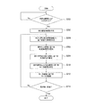
次に、図7に基づき、演算処理装置31で実行される目的地決定処理の処理手順について説明する。
演算処理装置31において、目的地決定処理が開始されると、図7に示すように、まず、ステップS100に移行する。
ステップS100では、目的地決定部52bの表示形態候補画像表示部521において、目的地設定メニューが選択されたことを示す選択情報M1が入力されたか否かを判定する。そして、入力されたと判定した場合(Yes)は、ステップS102に移行し、そうでないと判定した場合(No)は、選択情報M1が入力されるまで判定処理を繰り返す。
(Destination decision processing)
Next, based on FIG. 7, the processing procedure of the destination determination process performed with the
When the destination determination process is started in the
In step S100, it is determined whether or not selection information M1 indicating that the destination setting menu has been selected is input in the display form candidate
ステップS102に移行した場合は、表示形態候補画像表示部521において、画像格納部52cから表示形態候補画像データを読み出し、読み出した表示形態候補画像データに基づき表示形態候補画像をタッチパネルディスプレイ20に表示する。その後、ステップS104に移行する。
ステップS104では、表示形態候補画像表示部521において、表示形態候補画像が表示されているときのタッチパネルディスプレイ20からのタッチ位置の情報に基づき、表示形態候補が選択されたか否かを判定する。そして、選択されたと判定した場合(Yes)は、選択された表示形態候補を目的地候補画像の表示形態として設定し、設定した表示形態を示す表示形態情報DFを目的地決定部52bの目的地候補画像表示部522に出力して、ステップS106に移行する。一方、選択されていないと判定した場合(No)は、選択されるまで判定処理を繰り返す。
When the process proceeds to step S102, the display form candidate
In step S104, the display form candidate
なお、判定処理を繰り返すことに加えて、例えば「戻るボタン」を表示するように構成し、表示形態の選択前に「戻るボタン」がタッチされた場合に、メニュー画像の表示画面に戻るようにしてもよい。
ステップS106に移行した場合は、目的地候補画像表示部522において、表示形態情報DFの入力に応じて、画像格納部52cから表示形態情報DFに対応する目的地候補画像データを読み出し、読み出した目的地候補画像データに基づき、表示形態情報DFの示す表示形態の目的地候補画像をタッチパネルディスプレイ20に表示する。その後、ステップS108に移行する。
In addition to repeating the determination process, for example, a “return button” is displayed, and when the “return button” is touched before the display mode is selected, the menu image display screen is returned. May be.
When the process proceeds to step S106, the destination candidate
ここで、本実施形態の目的地候補画像表示部522は、表示形態情報DFの示す表示形態に対応する表示順番で配列された複数の目的地候補に対応する施設名の文字画像を含む目的地候補画像を表示する。そして、施設名毎にその表示位置をタッチすることで目的地を選択することが可能に構成されている。また、タッチ位置に対応する施設名の文字画像を強調表示し、選択していることが解るように表示処理する。なお、強調表示の形態としては、枠線で囲む、太字にする、文字の色を変更する、反転表示する等の形態がある。
また、目的地となる施設数が多くて、一画面に表示しきれない場合は、スクロールバー等によってスクロール表示するように構成されている。
Here, the destination candidate
Further, when the number of facilities serving as destinations is large and cannot be displayed on one screen, the display is scrolled by a scroll bar or the like.
ステップS108では、目的地候補画像表示部522において、タッチパネルディスプレイ20からのタッチ位置の情報に基づき、目的地候補が選択されたか否かを判定する。そして、選択されたと判定した場合(Yes)は、選択された目的地候補を目的地として設定して、ステップS110に移行し、そうでないと判定した場合(No)は、選択されるまで判定処理を繰り返す。
なお、判定処理を繰り返すことに加えて、例えば「戻るボタン」を表示するように構成し、目的地の選択前に「戻るボタン」がタッチされた場合に、表示形態候補画像の表示画面に戻るようにしてもよい。
ステップS110に移行した場合は、目的地候補画像表示部522において、ステップS108で設定した目的地を示す目的地情報ODをルート生成部52fに出力して、一連の処理を終了する。
In step S108, the destination candidate
In addition to repeating the determination process, for example, a “return button” is configured to be displayed. When the “return button” is touched before the destination is selected, the display screen returns to the display form candidate image. You may do it.
When the process proceeds to step S110, the destination candidate
(歩行支援処理)
次に、図8に基づき、演算処理装置31で実行される歩行支援処理の処理手順について説明する。
演算処理装置31において、歩行支援処理が実行されると、図8に示すように、まず、ステップS200に移行する。
ステップS200では、ルート生成部52fにおいて、目的地決定部52bからの目的地情報ODが入力されたか否かを判定する。そして、入力されたと判定した場合(Yes)は、ステップS202に移行し、そうでないと判定した場合(No)は、目的地情報ODが入力されるまで判定処理を繰り返す。
(Walking support processing)
Next, based on FIG. 8, the process procedure of the walk assistance process performed with the
When the walking support process is executed in the
In step S200, the
ステップS202に移行した場合は、ルート生成部52fにおいて、目的地決定部52bからの目的地情報ODと、自己位置補正部52eからの自己位置情報と、マップ格納部52gに格納されたフロア形状図とに基づき、走行経路情報を生成する。加えて、生成した走行経路情報と、音声設定メニューで設定された音声設定情報とに基づき、音声案内情報を生成する。そして、生成した走行経路情報を走行方向算出部51a及びナビゲーション画像表示部52hに出力し、生成した音声案内情報を音声出力部52iに出力して、ステップS204に移行する。
When the process proceeds to step S202, in the
ここで、ルート生成部52fは、例えば、ダイクストラ法を用いて走行経路情報を生成する。
また、ルート生成部52fは、自己位置補正部52eからの自己位置情報に基づき、案内用ロボット1が、走行経路上の音声案内が用意されているブロックに移動したときに、その都度、移動したブロックに対応する音声案内情報を音声出力部52iに出力するようになっている。
ステップS204に移行した場合は、走行方向算出部51aにおいて、自己位置情報と、走行経路情報とに基づき、案内用ロボット1の進行方向(旋回角度θ)を決定して、ステップS206に移行する。なお、直進の場合は、旋回角度θが0度となる。
Here, the
In addition, the
When the process proceeds to step S204, the travel
ステップS206では、走行方向算出部51aにおいて、操作入力部17を介した操作入力情報(力Fx、力Fz')に基づき、上式(1)に従って、案内用ロボット1の前後進速度V0を算出して、ステップS208に移行する。
ステップS208では、走行方向算出部51aにおいて、ステップS204で決定した旋回角度θと、ステップS206で算出した前後進速度V0と、予め設定した旋回半径rとに基づき、上式(2)に従って、案内用ロボット1の旋回速度ω0を算出する。その後、ステップS210に移行する。
In step S206, the traveling
In step S208, the travel
ステップS210では、モータ駆動制御部51dにおいて、前後進速度V及び旋回速度ωに基づき、第1及び第2電動モータ9L及び9Rの速度指令値を算出する。そして、この速度指令値を、速度指令値出力I/F62を介して第1及び第2モータドライバ61L及び61Rに出力して、ステップS212に移行する。
ステップS212では、第1及び第2モータドライバ61L及び61Rにおいて、速度指令値に基づき、第1及び第2電動モータ9L及び9Rを駆動制御する。これにより、案内用ロボット1が、走行経路に沿って直進走行又は旋回走行を行う。その後、ステップS214に移行する。
ステップS214では、走行方向算出部51aにおいて、自己位置情報と走行経路情報とに基づき、案内用ロボット1が目的地に到達したか否かを判定する。そして、到達したと判定した場合(Yes)は、歩行支援処理を終了する。一方、到達していないと判定した場合(No)は、ステップS204に移行する。
In step S210, the motor
In step S212, the first and
In step S214, the traveling
以上のように、案内用ロボット1は、自己位置(現在位置)及び走行経路に基づき進行方向を決定し、被案内者の入力した力Fyに基づき前後進速度V0を算出し、予め設定した旋回半径rと、前後進速度V0とに基づき旋回速度ω0を算出する。そして、算出した前後進速度V0及び旋回速度ω0に基づき、案内用ロボット1の走行制御を行う。
即ち、本実施形態の案内用ロボット1は、被案内者は前後進速度V0を指示するための操作を行うのみで、目的地までの進行方向(旋回角度θ)及び旋回速度ω0の決定は、案内用ロボット1が自律的に行うものである。
As described above, the guiding
That is, the
(動作)
次に、図9及び図10に基づき、本実施形態の動作について説明する。
被案内者が移動体2の後方に立ち、図示しない始動スイッチをオン状態とすると、移動体2に内蔵するバッテリの電力が走行制御装置30及び第1及び第2モータドライバ61L及び61Rに供給され、移動体2が走行可能状態となる。このとき、目的地が設定されていないため移動体2は停止状態を維持する。また、目的地案内部52は、電力の供給に応じて、図9(a)に示すように、タッチパネルディスプレイ20にメニュー画像MPを表示する。
(Operation)
Next, based on FIG.9 and FIG.10, operation | movement of this embodiment is demonstrated.
When the guided person stands behind the moving
メニュー画像MPは、図9(a)に示すように、画面上部に表示された「設定メニュー」のタイトルを示す第1タイトル画像TP1と、第1タイトル画像TP1の下部に表示された「目的地設定」の文字が描かれた目的地設定ボタン画像B1とを含んで構成される。更に、メニュー画像MPは、目的地設定ボタン画像B1の下部に表示された「地図設定」の文字が描かれた地図設定ボタン画像B2と、地図設定ボタン画像B2の下部に表示された「音声設定」の文字が描かれた音声設定ボタン画像B3とを含んで構成される。なお更に、メニュー画像MPは、画面右上隅に表示された「スタッフ呼出」の文字が描かれたスタッフ呼出ボタン画像SCを含んで構成される。 As shown in FIG. 9A, the menu image MP includes a first title image TP1 indicating the title of the “setting menu” displayed at the top of the screen and a “destination” displayed at the bottom of the first title image TP1. And a destination setting button image B1 on which “setting” is drawn. Further, the menu image MP includes a map setting button image B2 on which characters “map setting” displayed at the bottom of the destination setting button image B1 and a “voice setting” displayed at the bottom of the map setting button image B2. And a voice setting button image B3 on which the characters "" are drawn. Still further, the menu image MP includes a staff call button image SC on which characters “staff call” displayed in the upper right corner of the screen are drawn.
被案内者は、メニュー画像MPに表示された各設定ボタン画像B1〜B3の表示位置をタッチすることで所望の設定メニューを選択し、各設定メニュー画面に従って各設定を行うことが可能となっている。
なお、操作方法が良く解らない場合などの困ったことがあった場合は、スタッフ呼出ボタン画像SCの表示位置をタッチすることで、無線でスタッフまで連絡が届き、案内用ロボット1のところまでスタッフを呼び出すことが可能となっている。
メニュー画像が表示された状態で、被案内者が目的地を設定するためにタッチパネルディスプレイ20に表示された各設定ボタン画像B1〜B3のうち目的地設定ボタン画像B1の表示位置をタッチしたとする。これにより、タッチ位置の情報が目的地案内部52に入力される。
The guided person can select a desired setting menu by touching the display position of each setting button image B1 to B3 displayed on the menu image MP, and can perform each setting according to each setting menu screen. Yes.
If there is a problem, such as when the operation method is not well understood, the staff can be contacted wirelessly by touching the display position of the staff call button image SC, and the staff can reach the
In a state where the menu image is displayed, the guided person touches the display position of the destination setting button image B1 among the setting button images B1 to B3 displayed on the
目的地案内部52は、タッチ位置の情報から目的地設定ボタン画像B1がタッチされたことを判定し、図9(b)に示すように、表示形態候補画像FPをタッチパネルディスプレイ20に表示する。
表示形態候補画像FPは、図9(b)に示すように、画面上部に表示された「目的地設定」のタイトルを示す第2タイトル画像TP2と、第2タイトル画像TP2の下部に表示された「50音順」の文字が描かれた50音順選択ボタン画像B4と、50音順選択ボタン画像B4の下部に表示された「番号順」の文字が描かれた番号順選択ボタン画像B5と、番号順選択ボタン画像B5の下部に表示された「番号入力」の文字が描かれた番号入力選択ボタン画像B6とを含んで構成される。更に、表示形態候補画像FPは、画面右上隅に表示されたスタッフ呼出ボタン画像SCと、画面左下隅に表示された「戻る」の文字が描かれた戻るボタン画像RBとを含んで構成される。
The
As shown in FIG. 9B, the display form candidate image FP is displayed at the bottom of the second title image TP2 and the second title image TP2 indicating the title of “destination setting” displayed at the top of the screen. A 50-sound order selection button image B4 on which characters of “50-sound order” are drawn, and a number-order selection button image B5 on which characters of “number order” are displayed at the bottom of the 50-sound order selection button image B4, And a number input selection button image B6 on which characters of “number input” displayed at the bottom of the number order selection button image B5 are drawn. Further, the display form candidate image FP includes a staff call button image SC displayed at the upper right corner of the screen, and a return button image RB on which characters “return” displayed at the lower left corner of the screen are drawn. .
被案内者は、他の設定項目の設定を行いたい場合に戻るボタン画像RBの表示位置をタッチすることでメニュー画像MPの表示画面に戻ることが可能となっている。
そして、被案内者が、50音順選択ボタン画像B4の表示位置をタッチすることで、目的地案内部52は、そのタッチ位置の情報から50音順選択ボタン画像B4がタッチされたことを判定する。そして、図10(a)に示すように、タッチパネルディスプレイ20に、50音順の表示形態に対応する第1目的地候補画像OP1を表示する。
第1目的地候補画像OP1は、図10(a)に示すように、画面上部に表示された「目的地設定(50音順)」のタイトルを示す第3タイトル画像TP3と、第3タイトル画像TP3の下部に表示された案内用ロボット1が案内するエリア内に存在する複数の目的地候補の施設名を示す文字画像が50音順に配列された50音順画像FTとを含んで構成される。更に、第1目的地候補画像OP1は、50音順画像FTの下部に表示された「案内開始」の文字が描かれた案内開始ボタン画像IBと、画面右上隅に表示されたスタッフ呼出ボタン画像SCと、画面左下隅に表示された戻るボタン画像RBとを含んで構成される。
The guided person can return to the display screen of the menu image MP by touching the display position of the return button image RB to set other setting items.
Then, when the guided person touches the display position of the 50-sound order selection button image B4, the
As shown in FIG. 10A, the first destination candidate image OP1 includes a third title image TP3 indicating the title of “destination setting (in alphabetical order)” displayed at the top of the screen, and a third title image. It includes a 50-note order image FT in which character images indicating facility names of a plurality of destination candidates existing in the area guided by the
ここでは、案内用ロボット1が案内するエリアを総合病院とし、総合病院内に存在する各診療科の施設が目的地候補として設定されていることとする。診療科の施設としては、例えば、「心臓血管外科」、「脳神経外科」、「アレルギーリウマチ科」、「皮膚科」、「泌尿器科」などの施設があるとする。
従って、50音順画像FTは、図10(a)に示すように、「アレルギーリウマチ科」、「心臓血管外科」、「脳神経外科」、「皮膚科」、「泌尿器科」・・・といったように施設名を示す文字画像が50音順で上から順番に表示された画像となる。
Here, it is assumed that the area guided by the
Therefore, as shown in FIG. 10A, the 50-sound order image FT is “allergic rheumatology”, “cardiovascular surgery”, “brain surgery”, “dermatology”, “urology”, etc. The character images indicating the facility names are displayed in order from the top in the order of the Japanese syllabary.
また、ここでは、目的地候補となる診療施設数が多くて一画面内に全てを表示することができないこととする。そして、この対策として本実施形態では、50音順画像FTの施設名の表示欄の右端にスクロールバーSBを表示し、スクロールバーSBのタッチ操作によって施設名をスクロール表示可能な構成としている。被案内者は、表示欄に表示された複数の施設名のうちから目的とする施設名が見つからない場合は、スクロールバーSBをタッチ操作して表示欄の下側に移動させることで、他の施設名を表示欄内にスクロールして表示させることが可能となっている。 In addition, here, it is assumed that the number of medical facilities that are destination candidates is large and not all can be displayed in one screen. As a countermeasure, in this embodiment, the scroll bar SB is displayed at the right end of the facility name display field of the 50-sound order image FT, and the facility name can be scroll-displayed by a touch operation of the scroll bar SB. When the target facility name is not found from the plurality of facility names displayed in the display column, the guided person touches the scroll bar SB to move it to the lower side of the display column, The facility name can be scrolled and displayed in the display column.
そして、被案内者は、表示欄内に目的の施設名を見つけた場合、その施設名の表示位置をタッチすることで、ここでは施設名の文字画像が枠線FLで囲まれて強調表示され、この強調表示された状態で被案内者が案内開始ボタン画像IBの表示位置をタッチすることで強調表示された施設名の施設が選択され目的地として設定される。これにより、目的地が確定する。
このように、案内開始ボタン画像IBの表示位置をタッチするまでは、目的地が確定しないようになっているので、間違った施設名をタッチしてしまった場合に何度でもやり直すことが可能となっている。
また、現在の表示形態を変更したい場合は戻るボタン画像RBの表示位置をタッチすることで表示形態候補画像FPの表示画面に戻ることが可能となっている。
Then, if the guided person finds the target facility name in the display field, the character image of the facility name is highlighted and surrounded by the frame line FL by touching the display position of the facility name. In this highlighted state, when the guided person touches the display position of the guidance start button image IB, the highlighted facility name is selected and set as the destination. As a result, the destination is determined.
In this way, the destination is not fixed until the display position of the guidance start button image IB is touched, so that if the wrong facility name is touched, it can be repeated over and over again. It has become.
Further, when it is desired to change the current display form, it is possible to return to the display screen of the display form candidate image FP by touching the display position of the return button image RB.
一方、被案内者が、表示形態候補画像FPの表示画面で、番号順選択ボタン画像B5の表示位置をタッチした場合、目的地案内部52は、図10(b)に示すように、番号順の表示形態に対応する第2目的地候補画像OP2をタッチパネルディスプレイ20に表示する。
ここで、第2目的地候補画像OP2は、図10(b)に示すように、画面上部に表示された「目的地設定(番号順)」のタイトルを示す第4タイトル画像TP4と、第4タイトル画像TP4の下部に表示された案内用ロボット1が案内するエリア内に存在する複数の目的地候補の施設名を示す文字画像が番号順に配列された番号順画像NTとを含んで構成される。更に、第2目的地候補画像OP2は、番号順画像NTの下部に表示された案内開始ボタン画像IBと、画面右上隅に表示されたスタッフ呼出ボタン画像SCと、画面左下隅に表示された戻るボタン画像RBとを含んで構成される。
On the other hand, when the guided person touches the display position of the number order selection button image B5 on the display screen of the display form candidate image FP, the
Here, as shown in FIG. 10B, the second destination candidate image OP2 includes a fourth title image TP4 indicating the title of “destination setting (in order of numbers)” displayed on the upper part of the screen, and a fourth title image TP4. It includes a numbered image NT in which character images indicating facility names of a plurality of destination candidates existing in the area guided by the
ここでは、「皮膚科」、「心臓血管外科」、「脳神経外科」、「アレルギーリウマチ科」、「泌尿器科」に対して、例えば、通し番号として10、11、12、13、14がそれぞれ設定されていることとする。また、昇順で番号順に表示する表示形態であるとする。
従って、番号順画像NTは、図10(b)に示すように、・・・「10:皮膚科」、「11:心臓血管外科」、「12:脳神経外科」、「13:アレルギーリウマチ科」、「14:泌尿器科」・・・といったように通し番号及び施設名を示す文字画像が番号順で上から順番に表示された画像となる。
Here, for example, 10, 11, 12, 13, and 14 are set as serial numbers for “dermatology”, “cardiovascular surgery”, “brain neurosurgery”, “allergic rheumatology”, and “urology”, respectively. Suppose that Further, it is assumed that the display form is displayed in ascending order and numerical order.
Therefore, as shown in FIG. 10B, the number-ordered images NT are as follows: “10: Dermatology”, “11: Cardiovascular surgery”, “12: Neurosurgery”, “13: Allergic rheumatology” , “14: Urology”, etc., the character images indicating the serial numbers and facility names are displayed in order from the top in the order of the numbers.
また、50音順画像FTと同様に、施設数が多いことから、番号順画像NTの施設名の表示欄の右端にスクロールバーSBを表示し、スクロールバーSBのタッチ操作によって施設名をスクロール表示可能な構成としている。
そして、被案内者は、表示欄内に目的の施設名を見つけた場合、その施設名の表示位置をタッチすることで、タッチした施設名の文字画像が強調表示され、この強調表示された状態で案内開始ボタン画像IBの表示位置をタッチすることで強調表示された施設名の施設が選択され目的地として設定される。これにより、目的地が確定する。
Since the number of facilities is large as in the case of the FT-ordered image FT, the scroll bar SB is displayed at the right end of the facility name display field of the numbered order image NT, and the facility name is scroll-displayed by a touch operation of the scroll bar SB It has a possible configuration.
When the guided person finds the target facility name in the display field, the character image of the touched facility name is highlighted by touching the display position of the facility name, and this highlighted state is displayed. By touching the display position of the guidance start button image IB, the facility with the highlighted facility name is selected and set as the destination. As a result, the destination is determined.
また、被案内者が、表示形態候補画像DPの表示画面で、番号入力選択ボタン画像B6の表示位置をタッチした場合、目的地案内部52は、図10(c)に示すように、番号入力用画像NIPをタッチパネルディスプレイ20に表示する。
番号入力用画像NIPは、図10(c)に示すように、画面上部に表示された「目的地設定(番号入力)」のタイトルを示す第5タイトル画像TP5と、第5タイトル画像TP5の下部に表示された番号入力欄画像NIと、番号入力欄画像NIの右隣に表示された施設名表示欄画像DIと、番号入力欄画像NI及び施設名表示欄画像DIの下部に表示された1〜9までの9つの数字ボタン画像から構成される番号ボタン画像NBと、番号ボタン画像NBの右隣に表示された「削除」の文字が描かれた削除ボタン画像DBとを含んで構成される。加えて、番号入力用画像NIPは、番号ボタン画像NBの下部に表示された案内開始ボタン画像IBと、画面右上隅に表示されたスタッフ呼出ボタン画像SCと、画面左下隅に表示された戻るボタン画像RBとを含んで構成される。
Further, when the guided person touches the display position of the number input selection button image B6 on the display screen of the display form candidate image DP, the
As shown in FIG. 10C, the number input image NIP includes a fifth title image TP5 indicating the title of “destination setting (number input)” displayed at the top of the screen, and a lower portion of the fifth title image TP5. The number input field image NI displayed on the screen, the facility name display field image DI displayed on the right side of the number input field image NI, and the number input field image NI and the facility name display field image DI displayed at the bottom of the DI. The number button image NB composed of nine number button images ˜9 and the delete button image DB on which the character “delete” displayed on the right side of the number button image NB is drawn are configured. . In addition, the number input image NIP includes a guidance start button image IB displayed at the bottom of the number button image NB, a staff call button image SC displayed at the upper right corner of the screen, and a return button displayed at the lower left corner of the screen. And an image RB.
被案内者は、番号ボタン画像NBの各数字ボタン画像の表示位置をタッチすることで、番号入力欄画像NI上に目的の施設に対応する番号(ここでは2桁)を入力する。これにより、施設名表示欄画像DI上に入力した番号に対応する施設名の文字画像が表示される。この状態で、案内開始ボタン画像IBの表示位置をタッチすることで目的地が確定する。
即ち、本実施形態では、被案内者が目的地の番号を把握している場合などに、目的地に対応する番号を直接入力して目的地を設定できるようになっている。
The guided person touches the display position of each number button image of the number button image NB, and inputs the number (two digits here) corresponding to the target facility on the number input field image NI. Thereby, the character image of the facility name corresponding to the number input on the facility name display column image DI is displayed. In this state, the destination is determined by touching the display position of the guidance start button image IB.
That is, in the present embodiment, when the guided person knows the destination number, the destination can be set by directly inputting the number corresponding to the destination.
ここでも、案内開始ボタン画像IBをタッチするまでは、目的地が確定しないようになっているので、間違った番号を入力してしまった場合は、削除ボタン画像DBの表示位置をタッチして入力数字を削除して何度でも入力し直すことが可能となっている。
目的地が確定すると、目的地案内部52は、先ず、地図情報に含まれるフロア形状図に基づいて現在位置(スタート地点)から目的地までの走行経路を生成する。
目的地案内部52は、生成した走行経路情報を、走行制御部51に出力する。また、目的地案内部52は、生成した走行経路情報に含まれるブロックのうち、音声案内をすべき場所情報について音声案内情報を生成する。この音声案内情報による音声の出力は、案内用ロボット1が、音声案内を要するブロックに移動したときに行われる。
Again, the destination is not fixed until the guidance start button image IB is touched. If an incorrect number is entered, the display position of the delete button image DB is touched and entered. It is possible to delete numbers and re-enter as many times as you like.
When the destination is determined, the
The
また、目的地案内部52は、自己位置情報(現在位置情報)、走行経路情報及び障害物検出位置情報に基づきナビゲーション画像を生成し、生成したナビゲーション画像をタッチパネルディスプレイ20に表示する。ナビゲーション画像には、自己位置の周辺の地図画像、案内用ロボット1の現在位置を示すマーカ画像、走行経路を示す画像及び周辺のランドマークとなる施設の画像(施設名も表示)等が含まれている。目的地案内部52は、案内用ロボット1の移動に応じてナビゲーション画像を更新し、常に最新の自己位置に対応するナビゲーション画像を表示するようになっている。
被案内者は、ナビゲーション画像を見てランドマークとなる施設名などを確認しながら歩行することで、正しい経路を進んでいるかを容易に確認することが可能となる。
Further, the
The guided person can easily confirm whether he / she is walking on the correct route by walking while confirming the name of the facility to be a landmark by looking at the navigation image.
一方、走行制御部51は、目的地案内部52からの走行経路情報と自己位置情報(現在位置情報)とに基づき、走行方向を決定する。ここでは、直進移動をすることとして、走行制御部51は、進行方向として旋回角度θを0度に決定する。
その後、被案内者が操作入力部17のグリップ18を把持しながらY軸方向へ押すと、走行制御部51は、その操作入力情報(Fy及びFz')を入力する。すると、走行制御部51は、入力した操作入力情報に基づいて前後進速度V0を算出する。更に、走行制御部51は、前後進速度V0及び予め設定した旋回半径rとから旋回速度ω0を算出する。ここでは、直進移動するため、旋回速度ω0が0〔m/s〕となる。
On the other hand, the
Thereafter, when the guided person presses the
なお、力センサ19を、X軸回りのモーメントMxを検出可能な構成とした場合は、操作入力情報(Fy及びFz')だけでなく操作入力情報(Mx及びFz')に基づいて前後進速度V0を算出することが可能である。
そして、算出した前後進速度V0と旋回速度ω0とから前後進速度Vと旋回速度ωとが決定され、これらに基づいて第1及び第2電動モータ9L及び9Rを駆動するための速度指令値を第1及び第2モータドライバ61L及び61Rに出力する。
これにより、案内用ロボット1は、走行制御部51が決定した進行方向に向かって直進走行する。その後、案内用ロボット1が左折又は右折すべき位置に到達すると、走行制御部51は、目的地へと向かう方向へと移動すべく、新たな進行方向を決定する。ここでは、例えばT字路を右折することとして、走行制御部51は、右旋回方向に90度旋回する旋回角度θを決定する。引き続き、走行制御部51は、被案内者によるグリップ18の操作入力情報に基づいて前後進速度V0を算出し、この前後進速度V0と旋回半径rとから旋回速度ω0を算出する。そして、算出した前後進速度V0と旋回速度ω0とから前後進速度Vと旋回速度ωが決定され、これらに基づいて第1及び第2電動モータ9L及び9Rを駆動するための速度指令値を第1及び第2モータドライバ61L及び61Rに出力する。これにより、案内用ロボット1は、90度右旋回して、目的の方向へと向く。
When the
Then, the forward / reverse speed V and the turning speed ω are determined from the calculated forward / reverse speed V0 and the turning speed ω0, and based on these, speed command values for driving the first and second
Thereby, the
以降も上記同様に目的地に向かうための直進動作、旋回動作のための前後進速度Vと旋回速度ωを決定し、これらに基づいて第1及び第2電動モータ9L及び9Rを駆動するための速度指令値を第1及び第2モータドライバ61L及び61Rに出力する。これにより、案内用ロボット1を目的地へと向かって移動させる。
また、案内用ロボット1の移動途中で音声案内すべきブロックへと到達すると、目的地案内部52によって、現在、歩行中のブロックの場所情報等を音声で案内する。
その後、案内用ロボット1が、目的地へと到達すると、案内用ロボット1が停止すると共に、目的地案内部52によって、目的地に到達したことを知らせる音声案内が行われる。
Thereafter, the forward / backward speed V and the turning speed ω for the straight movement operation and the turning operation are determined in the same manner as described above, and the first and second
Further, when the
Thereafter, when the
なお、上記走行途中に、第1,第2障害物検出センサ22,24及び上方障害物センサ25の何れかで何らかの物体を検出した場合、それがフロア形状図に存在しない物体であれば、目的地案内部52は、検出した物体を障害物と見なして被案内者に障害物の接近を音声で知らせると共に、ナビゲーション画像上にマーカ表示して知らせる。
また、走行制御部51は、操作入力情報に基づいて算出した前後進速度V0及び旋回速度ω0を、障害物を回避する方向に補正し、それを最終的な前後進速度V及び旋回速度ωとして算出する。そして、算出した前後進速度V及び旋回速度ωに基づいて第1及び第2電動モータ9L及び9Rを駆動するための速度指令値を算出し、これを第1及び第2モータドライバ61L及び61Rに出力する。これにより、移動体2は、現在の走行方向を、障害物を回避する方向に変更して走行する。
If any object is detected by any of the first and second
Further, the traveling
また、案内の途中で操作入力部17のグリップ18へのZ'軸方向の力Fz'が無くなる(Fz'≦閾値)と、走行制御部51は、被案内者がグリップ18から手を放したと判断し、移動体2を停止する。これにより、案内用ロボット1が常に被案内者の手の届く範囲にいるようにすることができる。
ここで、第1及び第2電動モータ9L及び9Rがアクチュエータに対応し、走行制御部51が移動制御部に対応し、タッチパネルディスプレイ20が表示入力部に対応している。
Further, when the force Fz ′ in the Z′-axis direction on the
Here, the first and second
また、表示形態候補画像表示部521が表示形態候補画像表示部及び表示形態設定部に対応し、目的地候補画像表示部522が目的地候補画像表示部及び目的地設定部に対応している。
また、走行方向算出部51aが目標進行方向決定部に対応し、自己位置推定部52d及び自己位置補正部52eが自己位置推定部に対応し、ルート生成部52fが経路生成部に対応し、マップ格納部52gが地図情報格納部に対応している。
Further, the display form candidate
The travel
(実施形態の効果)
(1)本実施形態に係る案内用ロボット1は、移動体2が、第1及び第2電動モータ9L及び9Rから付与される駆動力によって任意の方向に移動可能に構成されている。タッチパネルディスプレイ20が、移動体2に取り付けられ、画像を表示する表示部と被案内者が表示部の表示面をタッチしたときのタッチ位置の情報を入力するタッチパネルとを備える。目的地候補画像表示部522が、表示パネルに、被案内者の案内先となる複数の目的地候補の情報を示す画像である目的地候補画像を表示する。目的地候補画像表示部522が、表示部に目的地候補画像が表示されているときのタッチ位置の情報に基づき、複数の目的地候補のうちからタッチ位置に対応する目的地候補を選択し、選択した目的地候補を目的地として設定する。マップ格納部52gが、移動体2が移動するエリアの地図情報を格納する。自己位置推定部52d及び自己位置補正部52eが、移動体2の現在位置を推定する。ルート生成部52fが、地図情報に基づき、自己位置推定部52d及び自己位置補正部52eで推定した現在位置から目的地候補画像表示部522で設定した目的地までの移動体2の移動経路を生成する。走行方向算出部51aが、自己位置推定部52d及び自己位置補正部52eで推定した現在位置とルート生成部52fで生成した移動経路とに基づき、移動体2の目標進行方向を決定する。走行制御部51が、走行方向算出部51aで決定した目標進行方向に基づき、第1及び第2電動モータ9L及び9Rを駆動制御して移動体2の移動を制御する。
(Effect of embodiment)
(1) The
この構成であれば、複数の目的地候補の情報を示す目的地候補画像をタッチパネルディスプレイ20の表示部に表示し、目的地候補画像の表示中に表示パネルの表示面を被案内者がタッチすることで、タッチ位置に対応する目的地候補を選択し、選択した目的地候補を目的地として設定することが可能となる。また、環境側に変更があっても目的地を選択するスイッチ等を追加することなくソフトウェアの変更によって簡易に対応することが可能となる。
これによって、複数の目的地候補が表示されている表示面における所望の目的地候補の表示位置をタッチするといった簡易な操作で目的地の設定を行うことが可能となり、例えば目的地の名称を入力するといった比較的複雑な操作を要する場合と比較して目的地の設定にかかる時間を低減することが可能となる。その結果、案内用ロボットが1人の被案内者によって占有される時間を短縮することが可能となり、案内用ロボットの稼動効率を向上することが可能となる。
With this configuration, a destination candidate image indicating information of a plurality of destination candidates is displayed on the display unit of the
This makes it possible to set the destination by a simple operation such as touching the display position of the desired destination candidate on the display surface on which a plurality of destination candidates are displayed. For example, the destination name can be input. It is possible to reduce the time required for setting the destination as compared with a case where a relatively complicated operation such as the above is required. As a result, it is possible to shorten the time for which the guidance robot is occupied by one guided person, and it is possible to improve the operation efficiency of the guidance robot.
(2)本実施形態に係る案内用ロボット1は、表示形態候補画像表示部521が、タッチパネルディスプレイ20に、目的地候補画像を表示する際の複数の表示形態候補の情報を示す表示形態候補画像を表示する。表示形態候補画像表示部521が、表示形態候補画像が表示されているときのタッチ位置の情報に基づき、複数の表示形態候補のうちからタッチ位置に対応する表示形態候補を表示形態として設定する。目的地候補画像表示部522が、表示形態候補画像表示部521で設定した表示形態で目的地候補画像を表示する。
この構成であれば、複数の目的地候補を表示する際に、その表示形態を複数の表示形態のうちから選択し、選択した表示形態で目的地候補画像を表示させることが可能となる。
これによって、被案内者が、目的地候補を見つけやすい好みの表示形態で目的地候補画像を表示させることが可能となり、目的地の設定にかかる時間をより低減することが可能となる。その結果、案内用ロボットが1人の被案内者によって占有される時間をより短縮することが可能となり、案内用ロボットの稼動効率をより向上することが可能となる。
(2) In the
With this configuration, when a plurality of destination candidates are displayed, the display form can be selected from among the plurality of display forms, and the destination candidate image can be displayed in the selected display form.
This makes it possible for the guideee to display the destination candidate image in a favorite display form that makes it easy to find the destination candidate, and to further reduce the time required for setting the destination. As a result, it is possible to further reduce the time that the guiding robot is occupied by one guided person, and it is possible to further improve the operation efficiency of the guiding robot.
(3)本実施形態に係る案内用ロボット1は、移動体2が、駆動輪6L及び6Rを備え、第1及び第2電動モータ9L及び9Rから付与される駆動力によって駆動輪6L及び6Rを回転駆動して任意の方向に走行可能な車輪型の移動体として構成されている。
この構成であれば、案内用ロボット1が車輪移動型ロボットとして構成されるので、脚型ロボット等と比較して簡易に旋回制御や速度制御等の移動制御を行うことが可能となる。
(3) In the guiding
With this configuration, since the guiding
(4)本実施形態に係る案内用ロボット1は、移動体2が移動するエリアが屋内であり、複数の目的地候補がエリア内に存在する複数の屋内施設である。
この構成であれば、案内用ロボット1を、屋内施設を案内するロボットとして構成することが可能となる。これによって、雨の降っている環境下等の屋外に特有の環境下での活動を考慮しなくて済むので、案内用ロボット1を比較的安価に製造することが可能となる。
(4) The
With this configuration, the guiding
(5)本実施形態に係る案内用ロボット1は、ナビゲーション画像表示部52hが、地図情報と自己位置推定部52d及び自己位置補正部52eで推定した現在位置とルート生成部52fで生成した移動経路とに基づき、表示部に現在位置の周辺の地図、現在位置及び移動経路の情報を示すナビゲーション画像を表示する。
この構成であれば、被案内者は、タッチパネルディスプレイ20の表示パネルに表示されたナビゲーション画像を見ながら案内を受けることが可能となる。
これによって、被案内者は、正しい経路を進んでいることを常に確認することが可能となり、安心して案内を受けることが可能となる。
(5) In the
With this configuration, the guided person can receive guidance while viewing the navigation image displayed on the display panel of the
As a result, the guided person can always confirm that he / she is traveling on the correct route, and can receive guidance with confidence.
(6)本実施形態に係る案内用ロボット1は、障害物検出部51bが、移動体2の周囲の障害物を検出する。走行制御部51が、障害物検出部51bで障害物を検出したとき、障害物を回避する方向に、移動体2の移動方向を補正する第1及び第2電動モータ9L及び9Rの駆動制御を行う。
この構成であれば、移動体2の周囲に障害物を検出した場合に、移動体2の移動方向を、障害物を回避する方向に補正する制御を行うことが可能となる。
これによって、障害物との接触を回避しながら移動体2の移動を継続することが可能となる。
(6) In the
With this configuration, when an obstacle is detected around the moving
Thereby, it becomes possible to continue the movement of the
(変形例)
(1)上記実施形態において、目的地候補の文字画像の表示位置をタッチすることで、目的地候補の文字画像を強調表示して選択していることが解るように構成したが、例えば、強調表示に加えて、選択された目的地候補の概要等を音声案内又は文字表示する構成としてもよい。例えば、施設名からどのような施設なのか解りづらい場合や似たような名称のものが複数ある場合などに、概要を音声案内又は文字表示することで被案内者が間違った目的地を設定することを低減することが可能となる。
(Modification)
(1) In the above-described embodiment, it is configured that the destination candidate character image is highlighted and selected by touching the display position of the destination candidate character image. In addition to the display, an outline or the like of the selected destination candidate may be provided by voice guidance or text display. For example, when it is difficult to understand what kind of facility it is from the facility name, or when there are multiple similar names, the guided person sets the wrong destination by voice guidance or text display This can be reduced.
(2)上記実施形態において、目的地候補となる施設名を漢字表示可能なものは漢字で表示する構成としたが、この構成に限らず、「カタカナ」や「ひらがな」のみで表示したり、ルビを表示したりするなど他の構成としてもよい。なお、目的地候補画像内に切り換えボタン画像を表示し、被案内者が切り換えボタン画像の表示位置をタッチすることで、表示を任意に切り換えることができる構成としてもよい。即ち、漢字が読めない場合などに「カタカナ」や「ひらがな」などの表示に切り換えられるようにすることで、目的地の設定時間の短縮や被案内者が間違った目的地を設定することを低減することが可能となる。 (2) In the above-described embodiment, the facility name that can be a destination candidate can be displayed in Kanji, but not limited to this configuration, it can be displayed only in “Katakana” or “Hiragana”, Other configurations such as displaying ruby may be used. It should be noted that the switching button image may be displayed in the destination candidate image, and the display can be arbitrarily switched by touching the display position of the switching button image. In other words, by switching to the display such as “Katakana” or “Hiragana” when Kanji characters cannot be read, etc., the destination setting time can be shortened and the guided user can set the wrong destination. It becomes possible to do.
(3)上記実施形態においては、障害物センサとして第1障害物検出センサ22,23,24を適用した場合について説明したが、超音波式センサ等の他の測距センサを適用することもできる。また、スキャナ式レンジセンサに代えて、1方向にレーザ光を出射する測距センサをZ軸方向に回動させて走査するようにしてもよい。
(4)上記実施形態においては、移動体2として、前側にキャスター5を設置し、後輪側に駆動輪6L及び6Rを設ける場合について説明したが、前側の左右位置に駆動輪を配置し、後輪側にキャスターを配置するようにしてもよい。
(3) In the above embodiment, the case where the first
(4) In the above embodiment, the case where the
(5)上記実施形態においては、移動体2を2輪駆動する場合について説明したが、自動車のように前後に2輪ずつ配置し、前後の一方を転舵輪とすることにより、走行方向を制御するようにしてもよい。この場合でも転舵輪の転舵量及び転舵角に基づいて走行軌跡を算出することができる。
(6)上記実施形態においては、ダイクストラ法を用いて走行経路を探索する構成としたが、この構成に限らない。例えば、ポテンシャル法、深さ優先探索、幅優先探索などの他のアルゴリズムを用いて経路を探索してもよい。
(5) In the above-described embodiment, the case where the
(6) In the above embodiment, the travel route is searched using the Dijkstra method. However, the present invention is not limited to this configuration. For example, the route may be searched using other algorithms such as a potential method, a depth-first search, and a width-first search.
1…案内用ロボット、2…移動体、3…基台、4…荷台部、5…キャスター、6L,6R…駆動輪、9L,9R…第1,第2電動モータ、11L,11R…タイミングベルト、12L,12R…ギアヘッド、15…支持腕、16…水平腕、17…操作入力部、18…グリップ、19…力センサ、20…タッチパネルディスプレイ、22,24…第1,第2障害物検出センサ、23…位置測位センサ、25…上方障害物センサ、30…走行制御装置、51…走行制御部、51a…走行方向算出部、51b…障害物検出部、51c…走行方向補正部、51d…モータ駆動制御部、52…目的地案内部、52a…メニュー画像表示部、52b…目的地決定部、52c…画像格納部、52d…自己位置推定部、52e…自己位置補正部、52f…ルート生成部、52g…マップ格納部、52h…ナビゲーション画像表示部、52i…音声出力部、53…センサ信号入力I/F、54…速度指令値出力I/F、55…回転速度位置入力I/F、56…画像出力I/F、57…タッチ位置入力I/F、58…音声出力I/F、61L,61R…第1,第2モータドライバ、62L,62R…第1,第2ロータリエンコーダ、67…スピーカ、521…表示形態候補画像表示部、522…目的地候補画像表示部
DESCRIPTION OF
Claims (6)
前記移動体に取り付けられ、画像を表示する表示部と被案内者が前記表示部の表示面をタッチしたときのタッチ位置を検出するタッチ位置検出部とを備えた表示入力装置と、
前記表示部に、前記被案内者の案内先となる複数の目的地候補の情報を示す画像である目的地候補画像を表示する目的地候補画像表示部と、
前記表示部に前記目的地候補画像が表示されているときの前記タッチ位置の情報に基づき、前記複数の目的地候補のうちからタッチ位置に対応する目的地候補を選択し、選択した目的地候補を目的地として設定する目的地設定部と、
前記移動体が移動するエリアの地図情報が格納された地図情報格納部と、
前記移動体の現在位置を推定する自己位置推定部と、
前記地図情報に基づき、前記自己位置推定部で推定した現在位置から前記目的地設定部で設定した目的地までの前記移動体の移動経路を生成する経路生成部と、
前記自己位置推定部で推定した現在位置と前記経路生成部で生成した移動経路とに基づき、前記移動体の目標進行方向を決定する目標進行方向決定部と、
前記目標進行方向決定部で決定した目標進行方向に基づき、前記アクチュエータを駆動制御して前記移動体の移動を制御する移動制御部と、を備えることを特徴とする案内用ロボット。 A movable body that is movable in any direction by a driving force applied from an actuator;
A display input device that is attached to the moving body and includes a display unit that displays an image and a touch position detection unit that detects a touch position when the guided person touches the display surface of the display unit;
A destination candidate image display unit that displays a destination candidate image that is an image indicating information of a plurality of destination candidates serving as guidance destinations for the guided person on the display unit;
Based on the information on the touch position when the destination candidate image is displayed on the display unit, the destination candidate corresponding to the touch position is selected from the plurality of destination candidates, and the selected destination candidate A destination setting section for setting as a destination,
A map information storage unit in which map information of an area in which the moving body moves is stored;
A self-position estimating unit for estimating a current position of the mobile body;
Based on the map information, a route generating unit that generates a moving route of the moving body from a current position estimated by the self-position estimating unit to a destination set by the destination setting unit;
A target travel direction determination unit that determines a target travel direction of the moving body based on the current position estimated by the self-position estimation unit and the travel route generated by the route generation unit;
A guidance robot comprising: a movement control unit that controls the movement of the moving body by driving the actuator based on the target traveling direction determined by the target traveling direction determination unit.
前記表示形態候補画像が表示されているときの前記タッチ位置の情報に基づき、前記複数の表示形態候補のうちからタッチ位置に対応する表示形態候補を表示形態として設定する表示形態設定部と、を備え、
前記目的地候補画像表示部は、前記表示形態設定部で設定した表示形態で前記目的地候補画像を表示する請求項1に記載の案内用ロボット。 A display form candidate image display unit for displaying a display form candidate image indicating information of a plurality of display form candidates when the destination candidate image is displayed on the display unit;
A display form setting unit that sets a display form candidate corresponding to the touch position as a display form from among the plurality of display form candidates based on the information on the touch position when the display form candidate image is displayed. Prepared,
The guidance robot according to claim 1, wherein the destination candidate image display unit displays the destination candidate image in a display form set by the display form setting unit.
前記移動制御部は、前記障害物検出部で障害物を検出したとき、前記障害物を回避する方向に、前記移動体の移動方向を補正する前記アクチュエータの駆動制御を行う請求項1から5のいずれか1項に記載の案内用ロボット。 An obstacle detection unit for detecting obstacles around the moving body;
The said movement control part performs drive control of the said actuator which correct | amends the moving direction of the said mobile body in the direction which avoids the said obstacle, when the said obstacle detection part detects an obstacle. The guidance robot according to claim 1.
Priority Applications (1)
| Application Number | Priority Date | Filing Date | Title |
|---|---|---|---|
| JP2015227613A JP2017097537A (en) | 2015-11-20 | 2015-11-20 | Guiding robot |
Applications Claiming Priority (1)
| Application Number | Priority Date | Filing Date | Title |
|---|---|---|---|
| JP2015227613A JP2017097537A (en) | 2015-11-20 | 2015-11-20 | Guiding robot |
Publications (2)
| Publication Number | Publication Date |
|---|---|
| JP2017097537A true JP2017097537A (en) | 2017-06-01 |
| JP2017097537A5 JP2017097537A5 (en) | 2019-01-10 |
Family
ID=58817000
Family Applications (1)
| Application Number | Title | Priority Date | Filing Date |
|---|---|---|---|
| JP2015227613A Pending JP2017097537A (en) | 2015-11-20 | 2015-11-20 | Guiding robot |
Country Status (1)
| Country | Link |
|---|---|
| JP (1) | JP2017097537A (en) |
Cited By (5)
| Publication number | Priority date | Publication date | Assignee | Title |
|---|---|---|---|---|
| WO2019044499A1 (en) * | 2017-09-04 | 2019-03-07 | 日本電産株式会社 | Mobile body, location estimation device, and computer program |
| CN111033425A (en) * | 2017-09-04 | 2020-04-17 | 日本电产株式会社 | Moving object, position estimation device, and computer program |
| CN114527743A (en) * | 2020-11-06 | 2022-05-24 | 熊机器人技术有限公司 | Method, system, and recording medium for controlling destination of robot |
| WO2023089867A1 (en) * | 2021-11-19 | 2023-05-25 | 村田機械株式会社 | Transport system |
| CN116817903A (en) * | 2023-08-24 | 2023-09-29 | 湖南大学 | Priori vision guidance-based intelligent robot global positioning method and system |
Citations (5)
| Publication number | Priority date | Publication date | Assignee | Title |
|---|---|---|---|---|
| JP2005221497A (en) * | 2004-02-05 | 2005-08-18 | Alpine Electronics Inc | Display method and system of navigation system |
| JP2010271911A (en) * | 2009-05-21 | 2010-12-02 | Nsk Ltd | Guiding robot and method for controlling the same |
| KR20150051709A (en) * | 2013-11-05 | 2015-05-13 | 임재호 | Walking aid device for patient safety |
| WO2015068229A1 (en) * | 2013-11-07 | 2015-05-14 | 富士機械製造株式会社 | Automatic driving system and automatic travel machine |
| JP2016024766A (en) * | 2014-07-24 | 2016-02-08 | 日本精工株式会社 | Robot for guidance |
-
2015
- 2015-11-20 JP JP2015227613A patent/JP2017097537A/en active Pending
Patent Citations (5)
| Publication number | Priority date | Publication date | Assignee | Title |
|---|---|---|---|---|
| JP2005221497A (en) * | 2004-02-05 | 2005-08-18 | Alpine Electronics Inc | Display method and system of navigation system |
| JP2010271911A (en) * | 2009-05-21 | 2010-12-02 | Nsk Ltd | Guiding robot and method for controlling the same |
| KR20150051709A (en) * | 2013-11-05 | 2015-05-13 | 임재호 | Walking aid device for patient safety |
| WO2015068229A1 (en) * | 2013-11-07 | 2015-05-14 | 富士機械製造株式会社 | Automatic driving system and automatic travel machine |
| JP2016024766A (en) * | 2014-07-24 | 2016-02-08 | 日本精工株式会社 | Robot for guidance |
Cited By (10)
| Publication number | Priority date | Publication date | Assignee | Title |
|---|---|---|---|---|
| WO2019044499A1 (en) * | 2017-09-04 | 2019-03-07 | 日本電産株式会社 | Mobile body, location estimation device, and computer program |
| CN111033425A (en) * | 2017-09-04 | 2020-04-17 | 日本电产株式会社 | Moving object, position estimation device, and computer program |
| CN111033426A (en) * | 2017-09-04 | 2020-04-17 | 日本电产株式会社 | Moving object, position estimation device, and computer program |
| JPWO2019044499A1 (en) * | 2017-09-04 | 2020-08-20 | 日本電産株式会社 | Moving object, position estimating device, and computer program |
| JP7111424B2 (en) | 2017-09-04 | 2022-08-02 | 日本電産シンポ株式会社 | Mobile object, position estimation device, and computer program |
| US11537140B2 (en) | 2017-09-04 | 2022-12-27 | Nidec-Shimpo Corporation | Mobile body, location estimation device, and computer program |
| CN114527743A (en) * | 2020-11-06 | 2022-05-24 | 熊机器人技术有限公司 | Method, system, and recording medium for controlling destination of robot |
| WO2023089867A1 (en) * | 2021-11-19 | 2023-05-25 | 村田機械株式会社 | Transport system |
| CN116817903A (en) * | 2023-08-24 | 2023-09-29 | 湖南大学 | Priori vision guidance-based intelligent robot global positioning method and system |
| CN116817903B (en) * | 2023-08-24 | 2023-11-21 | 湖南大学 | Priori vision guidance-based intelligent robot global positioning method and system |
Similar Documents
| Publication | Publication Date | Title |
|---|---|---|
| JP2017097537A (en) | Guiding robot | |
| Wachaja et al. | Navigating blind people with walking impairments using a smart walker | |
| Baker et al. | Improved interfaces for human-robot interaction in urban search and rescue | |
| JP4464893B2 (en) | Mobile robot | |
| US7788028B2 (en) | Navigation system | |
| US7577518B2 (en) | Navigation system | |
| JP6126139B2 (en) | Mobility assist robot | |
| KR20170109283A (en) | Vehicle and method for controlling vehicle | |
| JP7075822B2 (en) | Map information update system | |
| JP2017004102A (en) | Travel device, robot for guidance, and control method of travel device | |
| JP2016024766A (en) | Robot for guidance | |
| JP6638348B2 (en) | Mobile robot system | |
| JP2018120524A (en) | Guide robot | |
| JP6303784B2 (en) | Parking assistance device and parking assistance method | |
| JP2009220682A (en) | Parking assist device | |
| JPH10230862A (en) | Vehicular parking auxiliary device | |
| JP2015214221A (en) | Parking assist system and parking assist method | |
| JP2002036152A (en) | Autonomous moving robot | |
| JP6115296B2 (en) | Driving assistance device | |
| JP2010190593A (en) | Map display system | |
| CN116327570A (en) | Active guiding-oriented multi-mode autonomous driving blind guiding method and device | |
| JP2007017331A (en) | Navigation device | |
| JPWO2016199311A1 (en) | Mobile housing | |
| JP2015214220A (en) | Parking assist system and parking assist method | |
| JP2017124231A (en) | Moving aid robot |
Legal Events
| Date | Code | Title | Description |
|---|---|---|---|
| A521 | Request for written amendment filed |
Free format text: JAPANESE INTERMEDIATE CODE: A523 Effective date: 20181115 |
|
| A621 | Written request for application examination |
Free format text: JAPANESE INTERMEDIATE CODE: A621 Effective date: 20181115 |
|
| A131 | Notification of reasons for refusal |
Free format text: JAPANESE INTERMEDIATE CODE: A131 Effective date: 20190917 |
|
| A977 | Report on retrieval |
Free format text: JAPANESE INTERMEDIATE CODE: A971007 Effective date: 20190918 |
|
| A02 | Decision of refusal |
Free format text: JAPANESE INTERMEDIATE CODE: A02 Effective date: 20200317 |