JP2017084736A5 - - Google Patents
Download PDFInfo
- Publication number
- JP2017084736A5 JP2017084736A5 JP2015214798A JP2015214798A JP2017084736A5 JP 2017084736 A5 JP2017084736 A5 JP 2017084736A5 JP 2015214798 A JP2015214798 A JP 2015214798A JP 2015214798 A JP2015214798 A JP 2015214798A JP 2017084736 A5 JP2017084736 A5 JP 2017084736A5
- Authority
- JP
- Japan
- Prior art keywords
- contact
- receptacle
- plug
- connector
- island
- Prior art date
- Legal status (The legal status is an assumption and is not a legal conclusion. Google has not performed a legal analysis and makes no representation as to the accuracy of the status listed.)
- Granted
Links
- 230000000875 corresponding Effects 0.000 claims description 9
- 239000000969 carrier Substances 0.000 description 14
- 229910000679 solder Inorganic materials 0.000 description 4
- 238000005520 cutting process Methods 0.000 description 3
- 238000000034 method Methods 0.000 description 2
- 238000004519 manufacturing process Methods 0.000 description 1
- 238000003825 pressing Methods 0.000 description 1
- 238000005476 soldering Methods 0.000 description 1
Images


Description
図17乃至図19を参照すると、特許文献1には、回路基板930,980上に設置されると共に互いに接続可能な第1コネクタ900及び第2コネクタ950が開示されている。図17に示されるように、特許文献1の第1コネクタ900は、複数の第1端子910と、第1端子910を保持する第1ハウジング920とを備えている。第1端子910は、ソルダーテール部912を有している。第1ハウジング920には、複数の第1端子収容キャビティ922が形成されており、第1端子910は第1端子収容キャビティ922に夫々収容されている。図18に示されるように、特許文献1の第2コネクタ950は、複数の第2端子960と、第2端子960を保持する第2ハウジング970とを備えている。第2端子960は、ソルダーテール部962を有している。第2ハウジング970には、複数の第2端子収容キャビティ972が形成されており、第2端子960は第2端子収容キャビティ972に夫々収容されている。図19に示されるように、第1コネクタ900のソルダーテール部912は回路基板930の配線ランド932に半田付けされており、また第2コネクタ950のソルダーテール部962は回路基板980の配線ランド982に半田付けされている。第1コネクタ900と第2コネクタ950は夫々基板上に搭載された状態で互いに嵌合し、第1コネクタ900の第1端子910と第2コネクタ950の第2端子960とが夫々接続される。 Referring to FIGS. 17 to 19, Patent Document 1 discloses a first connector 900 and a second connector 950 that are installed on circuit boards 930 and 980 and can be connected to each other. As shown in FIG. 17, the first connector 900 of Patent Document 1 includes a plurality of first terminals 910 and a first housing 920 that holds the first terminals 910 . The first terminal 910 has a solder tail portion 912. A plurality of first terminal receiving cavities 922 are formed in the first housing 920, and the first terminals 910 are respectively stored in the first terminal receiving cavities 922. As shown in FIG. 18, the second connector 950 of Patent Document 1 includes a plurality of second terminals 960 and a second housing 970 that holds the second terminals 960. The second terminal 960 has a solder tail portion 962. A plurality of second terminal receiving cavities 972 are formed in the second housing 970, and the second terminals 960 are received in the second terminal receiving cavities 972, respectively. As shown in FIG. 19, the solder tail portion 912 of the first connector 900 is soldered to the wiring land 932 of the circuit board 930, and the solder tail portion 962 of the second connector 950 is soldered to the wiring land 982 of the circuit board 980. It is soldered to. The first connector 900 and the second connector 950 are fitted to each other while being mounted on the board, and the first terminal 910 of the first connector 900 and the second terminal 960 of the second connector 950 are connected to each other.
また、本発明は、第7のコネクタとして、第1乃至第5のいずれかのコネクタであって、
前記コネクタは、レセプタクルであり、
前記コンタクトは、弾性変形可能なバネ部と、前記バネ部に支持された接点とを更に有しており、
前記ハウジングは、2つ以上のレセプタクルコンタクト支持部と、2つ以上の島状部と、1つ以上のレセプタクル側凹部と、2つ以上の受容部とを更に有しており、
前記レセプタクルコンタクト支持部及び前記島状部は、前記コンタクト列に夫々対応しており、
前記レセプタクルコンタクト支持部は、前記ピッチ方向に長手を有しており、
前記島状部の夫々は、対応する前記コンタクト列の前記コンタクトの前記バネ部を部分的に収容しており、
前記島状部は、前記ピッチ方向に長手を有しており、
前記受容部は、前記所定方向において、前記2列以上の前記コンタクト列のうちの一つの前記コンタクト列に対応する前記レセプタクルコンタクト支持部と前記島状部との間に位置しており、
前記レセプタクル側凹部は、前記所定方向において、前記2列以上の前記コンタクト列のうちの一つの前記コンタクト列に対応する前記レセプタクルコンタクト支持部と前記2列以上の前記コンタクト列のうちの他の前記コンタクト列に対応する前記島状部との間に位置しており、
前記開口部は、前記レセプタクル側凹部内に位置している
コネクタを提供する。
Moreover, this invention is a connector in any one of 1st thru | or 5 as a 7th connector,
The connector is a receptacle;
The contact further includes an elastically deformable spring part and a contact point supported by the spring part,
The housing further includes two or more receptacle contact support portions, two or more island-shaped portions, one or more receptacle-side recesses, and two or more receiving portions,
The receptacle contact support portion and the island-shaped portion respectively correspond to the contact rows,
The receptacle contact support portion has a length in the pitch direction,
Each of the island-shaped portions partially accommodates the spring portion of the contact of the corresponding contact row,
The island-shaped portion has a longitudinal direction in the pitch direction,
The receiving portion is located between the receptacle contact support portion and the island-shaped portion corresponding to the one contact row of the two or more contact rows in the predetermined direction;
The receptacle-side recess includes, in the predetermined direction, the receptacle contact support portion corresponding to the one contact row of the two or more contact rows and the other of the two or more contact rows. Located between the islands corresponding to the contact rows,
The opening provides a <br/> connector that is located in the receptacle recess.
また、本発明は、第9のコネクタとして、第8のコネクタであって、
前記コンタクトは、被保持部と、湾曲部とを更に有しており、
前記湾曲部は、前記ピッチ方向及び前記所定方向の双方と直交する上下方向において前記被保持部と前記対向バネ部とから上方に延びると共に前記被保持部と前記対向バネ部とを連結しており、
前記湾曲部は、前記ピッチ方向と直交する面内において前記バネ部と比較して薄い厚みを有している
コネクタを提供する。
Moreover, this invention is an 8th connector as a 9th connector,
The contact further includes a held portion and a curved portion,
The curved portion extends upward from the held portion and the opposed spring portion in a vertical direction perpendicular to both the pitch direction and the predetermined direction, and connects the held portion and the opposed spring portion. ,
The curved portion provides a connector having a smaller thickness than the spring portion in a plane orthogonal to the pitch direction.
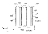
本実施の形態の複数のプラグコンタクト200は、4列のプラグコンタクト列を構成しており、プラグコンタクト列の夫々を構成するプラグコンタクト200は、ピッチ方向に並んでいる。プラグコンタクト200により構成されるプラグコンタクト列は、プラグコンタクト支持部151に夫々対応している。プラグコンタクト列の夫々は、対応するプラグコンタクト支持部151の+X側に位置している。開口部152は、所定方向において隣り合う2列のプラグコンタクト列の間に夫々位置している。プラグ側保持部156は、プラグコンタクト200と夫々対応している。
The plurality of
被固定部210は、プラグ100が回路基板(図示せず)上に搭載される際に回路基板(図示せず)に半田付けにより固定されるものである。図2及び図4に示されるように、プラグコンタクト列を構成するプラグコンタクト200のすべての被固定部210は、所定方向において、1つの開口部152に延びている。詳しくは、所定方向において隣り合う2列のプラグコンタクト列の一方のプラグコンタクト列を構成するプラグコンタクト200のすべての被固定部210は、1つの開口部152内に延びている。本実施の形態において、すべてのプラグコンタクト200の被固定部210は、+X方向に延びている。プラグコンタクト200の被固定部210は、第1主面159上に露出している。
The
図3及び図16より理解されるように、接触部212は、第1連結部211の+Z側端から+Z方向に延びている。
As understood from FIGS. 3 and 16, the
次に、キャリア切断用治具500を、プラグ100の開口部152に対して+Z側から上下方向に沿って挿入し、キャリア250と被固定部210との接続箇所252に対してキャリア切断用治具500の−Z側端部を押圧することにより、キャリア250をプラグコンタクト200から切り離す。これにより、プラグ100は図1に示される状態となる。このように、プラグ100においては、キャリア250に連結した複数のプラグコンタクト200をプラグハウジング150に組み込んだ後において、プラグコンタクト200からキャリア250を切り離す際に、開口部152からキャリア切断用治具500を挿入することにより複数のプラグコンタクト200から同時にキャリア250を分離することができる。さらに、一つのプラグコンタクト支持部151のプラグ側保持部156にプラグコンタクト200を取り付けた後、+X側に隣接するプラグコンタクト支持部151のプラグ側保持部156に対して同様にキャリア250に連結されたプラグコンタクト200を圧入することにより、順次プラグコンタクト200をプラグハウジング150に取り付ける。この際、被固定部210の向きが揃っていることから、既に圧入されたプラグコンタクト200の被固定部210とキャリア250とが接触することなく、この取付作業を行うことができる。これにより、プラグコンタクト200の破損を避けることができる。
Next, the
図12に示されるように、レセプタクルハウジング350に取り付けられる前の複数のレセプタクルコンタクト400は、キャリア490に接続された状態となっている。レセプタクルコンタクト400をレセプタクルハウジング350のレセプタクル側保持部354に対応させた状態で、第2連結部415を治具(図示せず)で押圧することにより、レセプタクルハウジング350に対してレセプタクルコンタクト400を一括して組み込むことができる。詳しくは、第2連結部415が押圧されると、レセプタクルコンタクト400が、レセプタクルハウジング350のレセプタクルコンタクト支持部353のレセプタクル側保持部354に対して−Z方向に夫々圧入され、レセプタクルコンタクト400の圧入部420はレセプタクルハウジング350の被圧入部352に食い込む。このようにして、レセプタクルコンタクト400の圧入部420は、レセプタクルハウジング350の被圧入部352に保持される。このとき、図6乃至図8及び図12から理解されるように、レセプタクル300を−Z側から上下方向に沿って見た場合、複数のレセプタクルコンタクト400の被固定部410は、レセプタクルハウジング350のレセプタクル側凹部357及び開口部351を通して視認できるようになっている。 As shown in FIG. 12, the plurality of receptacle contacts 400 before being attached to the receptacle housing 350 are connected to the carrier 490. In a state where the receptacle contact 400 corresponds to the receptacle-side holding portion 354 of the receptacle housing 350, the second connecting portion 415 is pressed with a jig (not shown), whereby the receptacle contacts 400 are collectively attached to the receptacle housing 350. Can be incorporated. Specifically, when the second connecting portion 415 is pressed, the receptacle contact 400 is press-fitted in the −Z direction with respect to the receptacle-side holding portion 354 of the receptacle contact support portion 353 of the receptacle housing 350, and the receptacle contact 400 is press-fitted. The portion 420 bites into the press-fit portion 352 of the receptacle housing 350. In this manner, the press-fit portion 420 of the receptacle contact 400 is held by the press-fit portion 352 of the receptacle housing 350. At this time, as can be understood from FIGS. 6 to 8 and FIG. 12, when the receptacle 300 is viewed from the −Z side along the vertical direction, the fixed portions 410 of the plurality of receptacle contacts 400 are arranged on the receptacle housing 350. It is visible through the receptacle-side recess 357 and the opening 351.
上述したプラグ100(図2参照)とレセプタクル300(図8参照)とを備えるコネクタ組立体10の接続は、以下に説明するように行われる。まず図13を参照して、上下方向において、プラグ100のプラグコンタクト200の被固定部210が露出している面、即ち第1主面159を−Z側に向けると共にレセプタクル300のレセプタクルコンタクト400の被固定部410が露出している面、即ち第2主面359を+Z側に向けたうえで、両者を上下方向において近づける。
Connection of the connector assembly 10 including the plug 100 (see FIG. 2 ) and the receptacle 300 (see FIG. 8 ) described above is performed as described below. First, referring to FIG. 13, in the vertical direction, the surface of the
Claims (2)
前記コネクタは、レセプタクルであり、
前記コンタクトは、弾性変形可能なバネ部と、前記バネ部に支持された接点とを更に有しており、
前記ハウジングは、2つ以上のレセプタクルコンタクト支持部と、2つ以上の島状部と、1つ以上のレセプタクル側凹部と、2つ以上の受容部とを更に有しており、
前記レセプタクルコンタクト支持部及び前記島状部は、前記コンタクト列に夫々対応しており、
前記レセプタクルコンタクト支持部は、前記ピッチ方向に長手を有しており、
前記島状部の夫々は、対応する前記コンタクト列の前記コンタクトの前記バネ部を部分的に収容しており、
前記島状部は、前記ピッチ方向に長手を有しており、
前記受容部は、前記所定方向において、前記2列以上の前記コンタクト列のうちの一つの前記コンタクト列に対応する前記レセプタクルコンタクト支持部と前記島状部との間に位置しており、
前記レセプタクル側凹部は、前記所定方向において、前記2列以上の前記コンタクト列のうちの一つの前記コンタクト列に対応する前記レセプタクルコンタクト支持部と前記2列以上の前記コンタクト列のうちの他の前記コンタクト列に対応する前記島状部との間に位置しており、
前記開口部は、前記レセプタクル側凹部内に位置している
コネクタ。 The connector according to any one of claims 1 to 5,
The connector is a receptacle;
The contact further includes an elastically deformable spring part and a contact point supported by the spring part,
The housing further includes two or more receptacle contact support portions, two or more island-shaped portions, one or more receptacle-side recesses, and two or more receiving portions,
The receptacle contact support portion and the island-shaped portion respectively correspond to the contact rows,
The receptacle contact support portion has a length in the pitch direction,
Each of the island-shaped portions partially accommodates the spring portion of the contact of the corresponding contact row,
The island-shaped portion has a longitudinal direction in the pitch direction,
The receiving portion is located between the receptacle contact support portion and the island-shaped portion corresponding to the one contact row of the two or more contact rows in the predetermined direction;
The receptacle-side recess includes, in the predetermined direction, the receptacle contact support portion corresponding to the one contact row of the two or more contact rows and the other of the two or more contact rows. Located between the islands corresponding to the contact rows,
The opening, <br/> connector that is located in the receptacle recess.
前記コンタクトは、被保持部と、湾曲部とを更に有しており、
前記湾曲部は、前記ピッチ方向及び前記所定方向の双方と直交する上下方向において前記被保持部と前記対向バネ部とから上方に延びると共に前記被保持部と前記対向バネ部とを連結しており、
前記湾曲部は、前記ピッチ方向と直交する面内において前記バネ部と比較して薄い厚みを有している
コネクタ。 The connector according to claim 8, wherein
The contact further includes a held portion and a curved portion,
The curved portion extends upward from the held portion and the opposed spring portion in a vertical direction perpendicular to both the pitch direction and the predetermined direction, and connects the held portion and the opposed spring portion. ,
The curved portion is a connector having a thickness smaller than that of the spring portion in a plane orthogonal to the pitch direction.
Priority Applications (3)
| Application Number | Priority Date | Filing Date | Title |
|---|---|---|---|
| JP2015214798A JP6635583B2 (en) | 2015-10-30 | 2015-10-30 | Connectors and connector assemblies |
| US15/221,004 US9728873B2 (en) | 2015-10-30 | 2016-07-27 | Connector mountable on a circuit board and connectable with a mating connector having a housing and rows of contacts with fixed portions extending into an opening of a housing |
| CN201610836536.6A CN106921056B (en) | 2015-10-30 | 2016-09-21 | Connector and connector assembly |
Applications Claiming Priority (1)
| Application Number | Priority Date | Filing Date | Title |
|---|---|---|---|
| JP2015214798A JP6635583B2 (en) | 2015-10-30 | 2015-10-30 | Connectors and connector assemblies |
Publications (3)
| Publication Number | Publication Date |
|---|---|
| JP2017084736A JP2017084736A (en) | 2017-05-18 |
| JP2017084736A5 true JP2017084736A5 (en) | 2018-08-02 |
| JP6635583B2 JP6635583B2 (en) | 2020-01-29 |
Family
ID=58635181
Family Applications (1)
| Application Number | Title | Priority Date | Filing Date |
|---|---|---|---|
| JP2015214798A Active JP6635583B2 (en) | 2015-10-30 | 2015-10-30 | Connectors and connector assemblies |
Country Status (3)
| Country | Link |
|---|---|
| US (1) | US9728873B2 (en) |
| JP (1) | JP6635583B2 (en) |
| CN (1) | CN106921056B (en) |
Families Citing this family (11)
| Publication number | Priority date | Publication date | Assignee | Title |
|---|---|---|---|---|
| KR20240017970A (en) * | 2018-07-06 | 2024-02-08 | 샘텍, 인코포레이티드 | Connector with top- and bottom-stitched contacts |
| JP7178893B2 (en) * | 2018-12-18 | 2022-11-28 | 日本航空電子工業株式会社 | CONNECTOR ASSEMBLY, CONNECTOR PAIR OF CONNECTOR ASSEMBLY, AND CONNECTOR ASSEMBLY MANUFACTURING METHOD |
| JP7178894B2 (en) * | 2018-12-18 | 2022-11-28 | 日本航空電子工業株式会社 | CONNECTOR ASSEMBLY, CONNECTOR PAIR OF CONNECTOR ASSEMBLY, AND CONNECTOR ASSEMBLY MANUFACTURING METHOD |
| CN209822934U (en) * | 2019-03-28 | 2019-12-20 | 东莞富强电子有限公司 | Spring plate |
| JP7366653B2 (en) * | 2019-09-06 | 2023-10-23 | 日本航空電子工業株式会社 | Connectors and connector manufacturing methods |
| JP7210415B2 (en) * | 2019-10-11 | 2023-01-23 | ヒロセ電機株式会社 | electrical connector |
| USD949798S1 (en) | 2019-12-06 | 2022-04-26 | Samtec, Inc. | Connector |
| TWM614957U (en) * | 2019-12-06 | 2021-08-01 | 美商山姆科技公司 | Electrical connector |
| CN113013650A (en) * | 2019-12-20 | 2021-06-22 | 中兴通讯股份有限公司 | Board-to-board connector and method of forming the same |
| USD958092S1 (en) | 2020-11-20 | 2022-07-19 | Samtec, Inc. | Contact |
| JP2022184291A (en) | 2021-06-01 | 2022-12-13 | 日本航空電子工業株式会社 | connector assembly |
Family Cites Families (14)
| Publication number | Priority date | Publication date | Assignee | Title |
|---|---|---|---|---|
| US5915976A (en) * | 1997-02-06 | 1999-06-29 | Hon Hai Precision Ind. Co., Ltd. | High speed connector |
| JPH10326651A (en) | 1997-05-27 | 1998-12-08 | Sumitomo Wiring Syst Ltd | Connector for board |
| JP3682649B2 (en) | 2001-11-27 | 2005-08-10 | 日本航空電子工業株式会社 | Connector device |
| KR20040072799A (en) * | 2003-02-11 | 2004-08-19 | 엘지전선 주식회사 | Structure of board to board connector |
| JP2006164594A (en) | 2004-12-03 | 2006-06-22 | Molex Inc | Substrate-to-substrate connector |
| JP4969838B2 (en) | 2005-11-28 | 2012-07-04 | モレックス インコーポレイテド | Floating type connector |
| JP2008270085A (en) * | 2007-04-24 | 2008-11-06 | Matsushita Electric Works Ltd | Connector |
| JP2009076337A (en) * | 2007-09-21 | 2009-04-09 | Jst Mfg Co Ltd | Card connector and connector base |
| JP2012099276A (en) | 2010-10-29 | 2012-05-24 | Jst Mfg Co Ltd | Contact and connector |
| JP5369125B2 (en) * | 2011-02-01 | 2013-12-18 | ヒロセ電機株式会社 | Electrical connector |
| JP5748334B2 (en) | 2011-05-31 | 2015-07-15 | 日本航空電子工業株式会社 | Connectors and connector units |
| JP5757794B2 (en) | 2011-06-14 | 2015-07-29 | モレックス インコーポレイテドMolex Incorporated | Multi-pole connector |
| JP5845029B2 (en) * | 2011-09-16 | 2016-01-20 | 日本航空電子工業株式会社 | Housingless connector |
| JP6148952B2 (en) * | 2013-03-14 | 2017-06-14 | 日本航空電子工業株式会社 | connector |
-
2015
- 2015-10-30 JP JP2015214798A patent/JP6635583B2/en active Active
-
2016
- 2016-07-27 US US15/221,004 patent/US9728873B2/en active Active
- 2016-09-21 CN CN201610836536.6A patent/CN106921056B/en active Active
Similar Documents
| Publication | Publication Date | Title |
|---|---|---|
| JP2017084736A5 (en) | ||
| JP6635583B2 (en) | Connectors and connector assemblies | |
| US9331410B2 (en) | Electrical connector | |
| US8109783B2 (en) | Insulation displacement connector (IDC) | |
| US9735484B2 (en) | Electrical connector system including electrical cable connector assembly | |
| US8758068B2 (en) | Contact spring for plug connector socket | |
| US20150311610A1 (en) | Board to board connector assembly having improved terminal arrangement | |
| EP3392984B1 (en) | Press-fit circuit board connector | |
| US20110294351A1 (en) | Board to board connector with low profile | |
| JP5737361B2 (en) | Connector terminal | |
| US8398422B2 (en) | Card edge connector | |
| JP2021089816A5 (en) | ||
| US8899997B2 (en) | Electrical connector with solder ball positioned in an insulative housing accurately | |
| US20120015564A1 (en) | Electrical connector with improved board lock and method of assembling the same | |
| US7938652B2 (en) | Low profile electrical connector | |
| JP5157784B2 (en) | Connection terminal structure, connector, and connector assembling method | |
| JP6076953B2 (en) | Board terminal | |
| US9136619B2 (en) | Electrical connector assembly | |
| JP7072857B2 (en) | Electrical connector | |
| US7581993B1 (en) | Socket connector | |
| JP4000865B2 (en) | Electrical connector | |
| EP2947719A1 (en) | Wire lug connector | |
| CN108336522B (en) | Connector assembly and method of manufacturing the same | |
| US6974355B1 (en) | Connector | |
| JP2016195061A (en) | connector |