JP2017070765A - Game machine - Google Patents
Game machine Download PDFInfo
- Publication number
- JP2017070765A JP2017070765A JP2016226238A JP2016226238A JP2017070765A JP 2017070765 A JP2017070765 A JP 2017070765A JP 2016226238 A JP2016226238 A JP 2016226238A JP 2016226238 A JP2016226238 A JP 2016226238A JP 2017070765 A JP2017070765 A JP 2017070765A
- Authority
- JP
- Japan
- Prior art keywords
- control unit
- effect
- game
- command
- winning
- Prior art date
- Legal status (The legal status is an assumption and is not a legal conclusion. Google has not performed a legal analysis and makes no representation as to the accuracy of the status listed.)
- Pending
Links
Images


Landscapes
- Pinball Game Machines (AREA)
Abstract
Description
本発明は、遊技球の入賞によって大当たりの抽選を行うパチンコ遊技機や遊技媒体の投
入の際の抽選結果を複数リールの停止時に図柄の組み合わせで表示するスロットマシン等
の遊技機に関するものである。
The present invention relates to a gaming machine such as a slot machine that displays a lottery result when a plurality of reels are stopped in a combination of symbols when a pachinko gaming machine that wins a jackpot by winning a game ball or a game medium is inserted.
パチンコ遊技機等の遊技機では、遊技球が始動口等の役物に入賞することにより大当た
りの抽選が行われる。そして、大当たりに当選した場合には、遊技機は、大入賞口が開放
されて、多くの賞球を獲得し得る大当たり遊技状態となる。また、遊技機では、遊技者に
よる遊技球の遊技に伴って、可動役物の動きや画像表示部での表示、各種のランプの点灯
、スピーカによる音響等の各種の演出が行われる。
演出に用いられる役物の構成として、従来から種々のものが提案されている(例えば、
特許文献1参照)。特許文献1は、可動役物装置は、第1可動役物を往復移動させる役物
駆動機構と、第1可動役物の移動範囲のうちの特定移動範囲における往復移動に連動して
第2可動役物を往復回動させる役物連動機構と、第1可動役物の往復移動方向のうちの一
方の移動方向へ第1可動役物を付勢するバネ部材を有するアシストバネ機構とを備える遊
技機を開示する。
In a gaming machine such as a pachinko machine, a big hit lottery is performed when a game ball wins a prize such as a start opening. When the jackpot is won, the gaming machine is put into a jackpot gaming state in which the jackpot is opened and many winning balls can be obtained. In the gaming machine, various effects such as the movement of the movable accessory, the display on the image display unit, the lighting of various lamps, the sound by the speaker, and the like are performed in accordance with the game of the game ball by the player.
As a composition of an accessory used for production, various things have been conventionally proposed (for example,
Patent Document 1).
ここで、可動物が所定位置に移動する動きを行う場合、そのような動きを繰り返すと所
定位置に対する位置精度が低下するおそれがあり、演出として好ましくないことが想定さ
れる。
本発明は、可動物の所定位置に対する位置精度の低下を防止することが可能な遊技機を
提供することを目的とする。
Here, when the movement of the movable object moves to a predetermined position, if such a movement is repeated, the position accuracy with respect to the predetermined position may be lowered, and it is assumed that it is not preferable as an effect.
An object of this invention is to provide the game machine which can prevent the fall of the positional accuracy with respect to the predetermined position of a movable object.
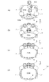
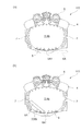
本発明が適用される遊技機は、動き演出を行う可動物(例えば上アゴ演出体4)を備え
る遊技機(例えばパチンコ遊技機100)であって、前記可動物(例えば上アゴ演出体4
)を係合部(例えば爪部46a6)との係合により所定位置(例えば原点位置)に保持す
る保持機構部(例えば左側機構46)を備え、前記保持機構部(例えば左側機構46)は
、変形可能な前記可動物(例えば上アゴ演出体4)を変形させるための機構(例えば引っ
掛け部材46d)を含んで構成されることを特徴とするものである。
A gaming machine to which the present invention is applied is a gaming machine (for example, pachinko gaming machine 100) including a movable object (for example, upper jaw effector 4) that performs a motion effect, and the movable object (for example, upper jaw effector 4).
) Is held at a predetermined position (for example, the origin position) by engaging with an engaging portion (for example, the claw portion 46a6), and the holding mechanism (for example, the left side mechanism 46) It is characterized by including a mechanism (for example, a hooking
なお、本欄における上記符号は、本発明の説明に際して例示的に付したものであり、こ
の符号により本発明が減縮されるものではない。
In addition, the said code | symbol in this column is attached | subjected illustratively in the description of this invention, and this invention is not reduced by this code | symbol.
本発明によれば、可動物の所定位置に対する位置精度の低下を防止することが可能にな
る。
ADVANTAGE OF THE INVENTION According to this invention, it becomes possible to prevent the fall of the position accuracy with respect to the predetermined position of a movable object.
以下、添付図面を参照して、本発明の実施の形態について詳細に説明する。
〔遊技機の基本構成〕
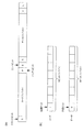
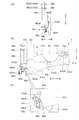
図1は、本実施の形態に係るパチンコ遊技機100の概略正面図である。
図1に示す遊技機の一例としてのパチンコ遊技機100は、遊技者の指示操作により打
ち出された遊技球が入賞すると賞球を払い出すように構成されたものである。このパチン
コ遊技機100は、遊技球が打ち出される遊技盤110と、遊技盤110を囲む枠部材1
50とを備えている。遊技盤110は、枠部材150に着脱自在に取り付けられている。
Embodiments of the present invention will be described below in detail with reference to the accompanying drawings.
[Basic configuration of gaming machine]
FIG. 1 is a schematic front view of a
A
50. The
遊技盤110は、前面に、遊技球により遊技を行うための遊技領域111と、下方から
発射された遊技球が上昇して遊技領域111の上部位置へ向かう通路を形成するレール部
材112と、遊技領域111の右側に遊技球を案内する案内部材113とを備えている。
本実施の形態では、遊技者により視認され易い遊技領域111の位置に、演出のための
各種の画像を表示する画像表示部114が配設されている。この画像表示部114は、液
晶ディスプレイ等による表示画面を備え、遊技者によるゲームの進行に伴い、例えば、特
別図柄抽選の判定結果を遊技者に報知するための装飾図柄を表示したり、キャラクタの登
場やアイテムの出現による演出画像や後述の保留表示を用いた演出画像を表示したりする
。
また、遊技盤110の前面に、各種の演出に用いられる可動役物115および盤ランプ
116を備えている。可動役物115は、遊技盤110上で動作することにより各種の演
出を行い、また、盤ランプ116は、発光することで各種の演出を行う。
The
In the present embodiment, an
In addition, a
遊技領域111には、遊技球が落下する方向に変化を与えるための図示しない遊技くぎ
および風車等が配設されている。また、遊技領域111には、入賞や抽選に関する種々の
役物が所定の位置に配設されている。また、遊技領域111には、遊技領域111に打ち
出された遊技球のうち入賞口に入賞しなかったものを遊技領域111の外に排出する排出
口117が配設されている。
The
本実施の形態では、入賞や抽選に関する種々の役物として、遊技球が入賞すると特別図
柄抽選(大当たり抽選)が始動する第1始動口121および第2始動口122と、遊技球
が通過すると普通図柄抽選(開閉抽選)が始動する始動ゲート(以下、単にゲートと呼ぶ
)124と、が遊技盤110に配設されている。なお、図1において、ゲート124は、
遊技領域111の左右にそれぞれ設けられており、左側のゲート124は124Lと記載
し、右側のゲート124は124Rと記載している。また、ここにいう第1始動口121
および第2始動口122とは、予め定められた1の特別図柄表示器の作動契機となる入賞
口をいう。具体的には、第1始動口121および第2始動口122には、入賞の際に遊技
球の通過を検知するスイッチ(後述の第1始動口スイッチ211および第2始動口スイッ
チ212)が設けられている。そして、第1始動口121または第2始動口122に遊技
球が入賞した際にこのスイッチが遊技球の通過を検知することが、特別図柄表示器を作動
させる契機となる。
In the present embodiment, as various functions related to winning and lottery, a special symbol lottery (a jackpot lottery) is started when a game ball wins, and when a game ball passes, it is normal. A start gate (hereinafter simply referred to as a gate) 124 for starting a symbol lottery (open / close lottery) is disposed on the
The
And the 2nd starting port 122 means the winning opening used as the operation opportunity of 1 special symbol display defined beforehand. Specifically, the
第2始動口122は、チューリップの花の形をした一対の羽根が電動ソレノイドにより
開閉作動すると共に点灯する普通電動役物としての電動チューリップ(開閉部材)123
を備えている。電動チューリップ123は、羽根が閉じていると、遊技球が第2始動口1
22へ入り難い一方で、羽根が開くと第2始動口122の入口が拡大して遊技球が第2始
動口122へ入り易くなるように構成されている。そして、電動チューリップ123は、
普通図柄抽選に当選すると、点灯ないし点滅しながら羽根が規定時間(例えば0.15秒
ないし1.8秒間)および規定回数(例えば1回ないし3回)だけ開く。
The second start port 122 is an electric tulip (opening / closing member) 123 as a normal electric accessory that is turned on and off when a pair of blades in the shape of tulip is opened and closed by an electric solenoid.
It has. When the electric tulip 123 is closed, the game ball moves to the
On the other hand, when the blade is opened, the entrance of the second start port 122 is expanded so that the game ball can easily enter the second start port 122. And the electric tulip 123
When the normal symbol lottery is won, the blades open for a specified time (for example, 0.15 to 1.8 seconds) and for a specified number of times (for example, 1 to 3 times) while lighting or flashing.
パチンコ遊技機100は、遊技状態として、特別図柄抽選の当選確率に基づき、当選確
率の低い低確率状態と、低確率状態よりも当選確率の高い高確率状態とを有している。そ
して、所定の条件に基づいて低確率状態と高確率状態とのいずれかの状態に制御される。
なお、上記の低確率状態と高確率状態の他に、特別図柄抽選の当選確率が低確率状態より
も高く高確率状態よりも低い中確率状態を設定することも可能である。この場合、パチン
コ遊技機100は、所定の条件に基づいて低確率状態、中確率状態および高確率状態のい
ずれかの状態に制御される。
また、パチンコ遊技機100は、第2始動口122への入賞機会が少ない時短無状態と
、時短無状態よりも第2始動口122への入賞機会が多い時短状態とを有している。そし
て、所定の条件に基づいて時短無状態と時短状態とのいずれかの状態に制御される。時短
状態とは、例えば、電動チューリップ123が開閉作動する際の開時間を延長すること、
普通図柄抽選の当たり当選確率を高確率にすること、あるいは普通図柄変動時間を短縮す
ること、のいずれか1つまたは複数の組合せによって制御される遊技状態である。なお、
時短状態では、特別図柄の特別図柄変動時間が短縮されていても良い。
The
In addition to the low probability state and the high probability state, it is possible to set a medium probability state in which the winning probability of the special symbol lottery is higher than the low probability state and lower than the high probability state. In this case, the
Further, the
This is a gaming state controlled by any one or a combination of increasing the probability of winning the normal symbol lottery or reducing the normal symbol variation time. In addition,
In the short time state, the special symbol variation time of the special symbol may be shortened.
また、本実施の形態では、入賞や抽選に関するその他の役物として、特別図柄抽選の結
果に応じて開放する特別電動役物としての大入賞口125と、遊技球が入賞しても抽選を
行わない普通入賞口126と、が遊技盤110に配設されている。
本実施の形態では、遊技盤110の左下の位置に、抽選結果や保留数に関する表示を行
う表示器130が配設されている。
Also, in this embodiment, as other prizes and lottery items, a lottery is performed even if a game ball wins a grand prize opening 125 as a special electric bonus that opens according to the result of the special symbol lottery. An ordinary winning
In the present embodiment, a
また、遊技盤110の裏面には、特別図柄抽選の判定等を含む遊技制御を行う遊技制御
基板、演出を統括的に制御する演出制御基板、画像および音による演出を制御する画像制
御基板、各種のランプおよび可動役物115による演出を制御するランプ制御基板などの
図示しない各種の基板等が取り付けられる。また、遊技盤110の裏面には、供給された
24VのAC電源をDC電源に変換して各種の基板等に出力するスイッチング電源(不図
示)が配設されている。
Also, on the back side of the
枠部材150は、遊技者がハンドル151に触れてレバー152を時計方向に回転させ
る操作を行うとその操作角度に応じた打球力にて遊技球を所定の時間間隔(例えば1分間
に100個)で電動発射する発射装置(不図示)を備えている。また、枠部材150は、
遊技者のレバー152による操作と連動したタイミングで発射装置に遊技球を1つずつ順
に供給する供給装置(不図示)と、供給装置が発射装置に供給する遊技球を一時的に溜め
ておく皿153と、を備えている。この皿153には、例えば払い出しユニットによる払
出球が払い出される。
なお、本実施の形態では、皿153を上下皿一体で構成しているが、上皿と下皿とを分
離する構成例も考えられる。また、発射装置のハンドル151を所定条件下で発光させた
り、振動させたりする構成例も考えられる。
When the player touches the
A supply device (not shown) for sequentially supplying game balls to the launching device one by one at a timing interlocked with the operation of the player's
In the present embodiment, the
また、枠部材150は、発射装置のハンドル151に遊技者が触れている状態であって
も遊技球の発射を一時的に停止させるための停止ボタン154と、皿153に溜まってい
る遊技球を箱(不図示)に落下させて取り出すための取り出しボタン155と、を備えて
いる。
また、枠部材150は、パチンコ遊技機100の遊技状態や状況を告知したり各種の演
出を行ったりするスピーカ156および枠ランプ157を備えている。スピーカ156は
、楽曲や音声、効果音により、告知や各種の演出を行う。枠ランプ157は、LED等の
発光体で構成され、点灯・点滅によるパターンや発光色の違い等で光による各種の演出を
行う。なお、枠ランプ157については、光の照射方向を変更する演出を行うことを可能
にする構成例が考えられる。
また、枠部材150には、開閉自在の前面枠(不図示)が設けられており、この前面枠
は、遊技盤110を遊技者と隔てるための透明板(不図示)を備えている。
Further, the
Further, the
The
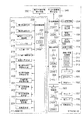
図2は、本実施の形態に係るパチンコ遊技機100を説明する図であり、図2(a)は
、遊技盤110の右下に配設された表示器130の一例を示す拡大図であり、図2(b)
は、パチンコ遊技機100の部分平面図である。
パチンコ遊技機100の表示器130は、図2(a)に示すように、第1始動口121
の入賞に対応して作動する第1特別図柄表示器221と、第2始動口122の入賞に対応
して作動する第2特別図柄表示器222と、ゲート124の通過に対応して作動する普通
図柄表示器223と、を備えている。第1特別図柄表示器221は、第1始動口121の
入賞に基づき、特別図柄を変動表示した後に停止表示させて抽選結果を表示する。第2特
別図柄表示器222は、第2始動口122の入賞に基づき、特別図柄を変動表示した後に
停止表示させて抽選結果を表示する。普通図柄表示器223は、遊技球がゲート124を
通過したことに基づき、普通図柄を変動表示した後に停止表示させて抽選結果を表示する
。本実施の形態では、第1特別図柄表示器221、第2特別図柄表示器222は、各々L
EDを配列した表示装置で構成され、その点灯態様によって特別図柄抽選の抽選結果が表
示される。同様に、普通図柄表示器223も、LEDを配列した表示装置で構成され、そ
の点灯態様によって普通図柄抽選の抽選結果が表示される。
FIG. 2 is a view for explaining the
These are partial plan views of the
As shown in FIG. 2A, the
The first
A lottery result of a special symbol lottery is displayed depending on the lighting mode. Similarly, the
また、表示器130は、第1特別図柄表示器221での保留に対応して作動する第1特
別図柄保留表示器218と、第2特別図柄表示器222での保留に対応して作動する第2
特別図柄保留表示器219と、普通図柄表示器223での保留に対応して作動する普通図
柄保留表示器220と、を備えている。本実施の形態では、第1特別図柄保留表示器21
8、第2特別図柄保留表示器219および普通図柄保留表示器220は、各々LEDを配
列した表示装置で構成され、その点灯態様によって保留数が表示される。
In addition, the
A special
8. The second special
ここで、保留について説明する。特別図柄の変動表示動作中(入賞1回分の変動表示が
行なわれている間)にさらに第1始動口121または第2始動口122に遊技球が入賞し
た場合、特別図柄が変動中であるために、後の入賞に基づく特別図柄の変動表示動作を開
始することができない。そのため、後の入賞は規定個数(例えば4個)を限度に記憶され
、その入賞した遊技球に対する特別図柄を始動させるための権利が、先に入賞した遊技球
に対する変動表示動作が終了するまで、保留される。なお、普通図柄に関しても、特別図
柄と同様の処理を行う。このような保留がなされていることおよびその保留の数(未変動
数)が、第1特別図柄保留表示器218、第2特別図柄保留表示器219および普通図柄
保留表示器220に表示される。
Here, the hold will be described. If a game ball wins in the
さらに、表示器130は、パチンコ遊技機100の状態を表示する状態表示器224を
備えている。本実施の形態では、状態表示器224は、3個のLEDを配列した表示装置
で構成されている。3個のLEDのうち1つは、パチンコ遊技機100の状態が、特別図
柄抽選の当選確率が高確率である高確率状態となっているか否かを点灯により報知するも
のである。他の1つは、パチンコ遊技機100の状態が、第2始動口122に入賞しやす
い時短状態となっているか否かを点灯により報知するものである。さらに他の1つは、右
打ちすることによって(遊技球の打球力を変更することによって)遊技者に有利な状態と
なっているか否かを点灯により報知するものである。なお、状態表示器224には、さら
にLEDを設け、他の遊技状態に関する情報を報知するようにしても良い。
Furthermore, the
また、表示器130は、特別図柄抽選の抽選結果に応じて行われる大当たり遊技におい
て大入賞口125が作動される際のラウンド数を表示するラウンド数表示器225を備え
ている。大当たり遊技については後述する。ラウンド数表示器225は、LEDを配列し
た表示装置で構成され、その点灯態様によって大当たり遊技における大入賞口125の作
動ラウンド数が表示される。
In addition, the
パチンコ遊技機100の枠部材150は、遊技者が演出に対する入力を行うための入力
装置を備えている。図2(b)に示すように、本実施の形態では、入力装置の一例として
、演出ボタン161と、演出ボタン161に隣接し、略十字に配列された複数のキーから
なる演出キー162と、が枠部材150に配設されている。例えば、演出において複数の
画像の中から1つの画像を選択する操作を受け付ける場合を考える。この場合、例えば、
遊技者は、十字に配列された4つのキーからなる演出キー162を操作することにより、
画像表示部114に表示されている複数の画像のいずれかを指示し、演出ボタン161を
操作することにより、指示した画像を選択するような演出を採用することができる。また
、入力装置の形態としては、図示した演出ボタン161および演出キー162の他、レバ
ーやダイヤル等、演出の内容等に応じて様々な入力形態を採用することができる。
The
The player operates an
By directing one of the plurality of images displayed on the
〔制御ユニットの構成〕
次に、パチンコ遊技機100での動作制御や信号処理を行う制御ユニットについて説明
する。
図3は、制御ユニットの内部構成を示すブロック図である。図3に示すように、制御ユ
ニットは、メイン制御手段として、特別図柄の当選の判定等を行う遊技制御部200を備
えている。また、サブ制御手段として、演出を統括的に制御する演出制御部300と、画
像および音響を用いた演出を制御する画像/音響制御部310と、各種のランプおよび可
動役物115を用いた演出を制御するランプ制御部320と、払出球の払い出し制御を行
う払出制御部330と、を備えている。
[Configuration of control unit]
Next, a control unit that performs operation control and signal processing in the
FIG. 3 is a block diagram showing an internal configuration of the control unit. As shown in FIG. 3, the control unit includes a
メイン制御手段である遊技制御部200は、メイン基板としての図示しない遊技制御基
板により構成されている。また、サブ制御手段である演出制御部300、画像/音響制御
部310、ランプ制御部320および払出制御部330の各々は、サブ基板としての図示
しない演出制御基板、画像制御基板、ランプ制御基板、および払出制御基板により個別に
構成されている。
The
〔遊技制御部の構成・機能〕
遊技制御部200は、特別図柄抽選の抽選結果の判定等を行う際の演算処理を行うCP
U201と、CPU201にて実行されるプログラムや各種データ等が記憶されたROM
202と、CPU201の作業用メモリ等として用いられるRAM203と、を備えてい
る。
[Configuration and function of game control unit]
The
U201 and ROM storing programs executed by
202 and a
遊技制御部200は、パチンコ遊技機100の遊技状態を、高確率状態または低確率状
態のいずれか、時短無状態または時短状態のいずれかで制御する。これにより、パチンコ
遊技機100の遊技状態は、高確率状態および時短状態である高確率時短遊技状態、低確
率状態および時短状態である低確率時短遊技状態、高確率状態および時短無状態である高
確率時短無遊技状態、低確率状態および時短無状態である低確率時短無遊技状態のいずれ
かとなる。そして、遊技制御部200は、所定の条件に基づき、高確率状態と低確率状態
とを切り替え、時短無状態と時短状態とを切り替える。また、遊技制御部200は、時短
状態において、時短無状態よりも普通図柄抽選の当たり当選確率を高確率にする、普通図
柄変動時間を短縮する、電動チューリップ123の開時間を延長する等の制御を行う。
The
遊技制御部200は、第1始動口121または第2始動口122に遊技球が入賞したこ
とを契機として特別図柄抽選を行う。そして、特別図柄抽選の判定結果に応じて大当たり
遊技等の特別遊技を行う。特別遊技において、遊技制御部200は、特別電動役物である
大入賞口125が所定条件(例えば29.5秒経過または遊技球10個の入賞)を満たす
まで開状態を維持するラウンドを所定回数だけ繰り返すように制御する。そして、遊技制
御部200は、大当たり大入賞口125が開く際の開閉動作間隔を制御する。
The
また、遊技制御部200は、ゲート124を遊技球が通過したことを契機として普通図
柄抽選を行う。そして、普通図柄抽選の判定結果に応じて電動チューリップの作動を制御
する。
また、遊技制御部200は、特別図柄変動中に遊技球が第1始動口121または第2始
動口122へ入賞したことにより発生する保留や、普通図柄変動中に遊技球がゲート12
4を通過したことにより発生する保留の設定を行う。
さらに、遊技制御部200は、特別図柄抽選および普通図柄抽選の判定結果、高確率状
態と低確率状態の変更情報、時短無状態と時短状態の変更情報、保留の設定情報等の遊技
制御に伴う情報を演出制御部300に送る。
In addition, the
In addition, the
Set the hold generated by passing 4.
Further, the
さらに、遊技制御部200は、第1始動口121、第2始動口122、大入賞口125
および普通入賞口126に遊技球が入賞すると、遊技球が入賞した場所に応じて1つの遊
技球当たり所定数の賞球を払い出すように、払出制御部330に対する指示を行う。例え
ば、第1始動口121に遊技球が入賞すると3個の賞球、第2始動口122に遊技球が入
賞すると4個の賞球、大入賞口125に遊技球が入賞すると13個の賞球、普通入賞口1
26に遊技球が入賞すると10個の賞球をそれぞれ払い出すように、払出制御部330に
指示命令(コマンド)を送る。なお、ゲート124を遊技球が通過したことを検出しても
、それに連動した賞球の払い出しは払出制御部330に指示しない。
払出制御部330が遊技制御部200の指示に従って賞球の払い出しを行った場合には
、遊技制御部200は、払い出した賞球の個数に関する情報を払出制御部330から取得
する。それにより、払い出した賞球の個数を管理する。
Furthermore, the
When a game ball wins the
When a game ball wins in 26, an instruction command (command) is sent to the
When the
遊技制御部200には、検知手段として、図3に示すように、第1始動口121への遊
技球の入賞を検出する第1始動口検出部(第1始動口スイッチ(SW))211と、第2
始動口122への遊技球の入賞を検出する第2始動口検出部(第2始動口スイッチ(SW
))212と、電動チューリップ123を開閉する電動チューリップ開閉部213と、ゲ
ート124への遊技球の通過を検出するゲート検出部(ゲートスイッチ(SW))214
と、が接続されている。
さらに、遊技制御部200には、大入賞口125への遊技球の入賞を検出する大入賞口
検出部(大入賞口スイッチ(SW))215と、大入賞口125を閉状態と突出傾斜した
開状態とに設定する大入賞口開閉部216と、普通入賞口126への遊技球の入賞を検出
する普通入賞口検出部(普通入賞口スイッチ(SW))217と、が接続されている。
As shown in FIG. 3, the
A second start port detector (second start port switch (SW
)) 212; an electric tulip opening /
And are connected.
Further, the
また、遊技制御部200には、特別図柄の変動中に第1始動口121へ入賞した未変動
分の保留個数を表示する第1特別図柄保留表示器218と、特別図柄の変動中に第2始動
口122へ入賞した未変動分の保留個数を表示する第2特別図柄保留表示器219と、普
通図柄の変動中にゲート124を通過した未変動分の保留個数を表示する普通図柄保留表
示器220と、が接続されている。
さらに、遊技制御部200には、第1始動口121への遊技球の入賞により行われる特
別図柄の変動表示および特別図柄抽選の結果を表示する第1特別図柄表示器221と、第
2始動口122への遊技球の入賞により行われる特別図柄の変動表示および特別図柄抽選
の結果を表示する第2特別図柄表示器222と、普通図柄の変動表示および普通図柄抽選
の結果を表示する普通図柄表示器223と、パチンコ遊技機100の状態を表示する状態
表示器224と、が接続されている。
In addition, the
Further, the
そして、第1始動口スイッチ211、第2始動口スイッチ212、ゲートスイッチ21
4、大入賞口スイッチ215および普通入賞口スイッチ217にて検出された検出信号が
、遊技制御部200に送られる。また、遊技制御部200からの制御信号が、電動チュー
リップ開閉部213、大入賞口開閉部216、第1特別図柄保留表示器218、第2特別
図柄保留表示器219、普通図柄保留表示器220、第1特別図柄表示器221、第2特
別図柄表示器222、普通図柄表示器223および状態表示器224に送られる。それに
より、遊技制御部200は、上記した払い出し賞球数に関連する各種制御を行う。
The first
4. The detection signals detected by the big
さらに、遊技制御部200には、ホールに設置されたホストコンピュータ(不図示)に
対して各種の情報を送信する盤用外部情報端子基板350が接続されている。そして、遊
技制御部200は、払出制御部330から取得した、払い出した賞球数に関する情報や遊
技制御部200の状態等を示す情報を、盤用外部情報端子基板350を介してホストコン
ピュータに送信する。
Further, a board external
〔演出制御部の構成・機能〕
演出制御部300は、演出を制御する際の演算処理を行うCPU301と、CPU30
1にて実行されるプログラムや各種データ等が記憶されたROM302と、CPU301
の作業用メモリ等として用いられるRAM303と、日時を計測するリアルタイムクロッ
ク(RTC)304と、を備えている。
演出制御部300は、例えば遊技制御部200から送られる特別図柄抽選での当選か否
かの判定結果および変動パターンに基づいて、演出内容を設定する。その際、演出ボタン
161または演出キー162を用いたユーザからの操作入力を受けて、操作入力に応じた
演出内容を設定する場合もある。この場合、例えば演出ボタン161等のコントローラ(
不図示)から操作に応じた信号(操作信号)を受け付け、この操作信号により識別される
操作内容を演出の設定に反映させる。
また、演出制御部300は、遊技が所定期間中断された場合には、演出の1つとして客
待ち用の画面表示の設定を指示する。
さらには、演出制御部300は、遊技制御部200より受信した高確率状態と低確率状
態の変更情報、時短無状態と時短状態の変更情報に基づいて演出内容を設定する。
また、演出制御部300は、設定した演出内容の実行を指示するコマンドを画像/音響
制御部310およびランプ制御部320に送る。
[Configuration and function of production control unit]
The
A
The
A signal (operation signal) corresponding to the operation is received from (not shown), and the operation content identified by this operation signal is reflected in the setting of the effect.
In addition, when the game is interrupted for a predetermined period, the
Furthermore, the
In addition, the
〔画像/音響制御部の構成・機能〕
画像/音響制御部310は、演出内容を表現する画像および音響を制御する際の演算処
理を行うCPU311と、CPU311にて実行されるプログラムや各種データ等が記憶
されたROM312と、CPU311の作業用メモリ等として用いられるRAM313と
、を備えている。
そして、画像/音響制御部310は、演出制御部300から送られたコマンドに基づい
て、画像表示部114に表示する画像およびスピーカ156から出力する音響を制御する
。
具体的には、画像/音響制御部310のROM312には、画像表示部114において
遊技中に表示する図柄画像や背景画像、遊技者に抽選結果を報知するための装飾図柄、遊
技者に予告演出を表示するためのキャラクタやアイテム等といった画像データが記憶され
ている。
ROM312には、さらに、画像データと同期させて、または画像データとは独立にス
ピーカ156から出力させる楽曲や音声、さらにはジングル等の効果音等といった各種音
響データが記憶されている。CPU311は、ROM312に記憶された画像データや音
響データの中から、演出制御部300から送られたコマンドに対応したものを選択して読
み出す。さらには、読み出した画像データを用いて背景画像表示、図柄画像表示、図柄画
像変動、およびキャラクタ/アイテム表示等のための画像処理と、読み出した音響データ
を用いた音声処理とを行う。
そして、画像/音響制御部310は、画像処理された画像データにより画像表示部11
4での画面表示を制御する。また、音声処理された音響データによりスピーカ156から
出力される音響を制御する。
[Configuration / Function of Image / Sound Control Unit]
The image /
Then, the image /
Specifically, in the
The
Then, the image /
4 controls the screen display. Further, the sound output from the
〔ランプ制御部の構成・機能〕
ランプ制御部320は、盤ランプ116や枠ランプ157の発光、および可動役物11
5の動作を制御する際の演算処理を行うCPU321と、CPU321にて実行されるプ
ログラムや各種データ等が記憶されたROM322と、CPU321の作業用メモリ等と
して用いられるRAM323と、を備えている。
そして、ランプ制御部320は、演出制御部300から送られたコマンドに基づいて、
盤ランプ116や枠ランプ157の点灯/点滅や発光色等を制御する。また、可動役物1
15の動作を制御する。
具体的には、ランプ制御部320のROM322には、演出制御部300にて設定され
る演出内容に応じた盤ランプ116や枠ランプ157での点灯/点滅パターンデータおよ
び発光色パターンデータ(発光パターンデータ)が記憶されている。CPU321は、R
OM322に記憶された発光パターンデータの中から、演出制御部300から送られたコ
マンドに対応したものを選択して読み出す。そして、ランプ制御部320は、読み出した
発光パターンデータにより盤ランプ116や枠ランプ157の発光を制御する。
また、ランプ制御部320のROM322には、演出制御部300にて設定される演出
内容に応じた可動役物115の動作パターンデータが記憶されている。CPU321は、
可動役物115に対しては、読み出した動作パターンデータによりその動作を制御する。
[Configuration and function of lamp control unit]
The
5, a
And the
The lighting / flashing of the
15 operations are controlled.
Specifically, the
From the light emission pattern data stored in the
The
The operation of the
〔払出制御部の構成・機能〕
払出制御部330は、払出球の払い出しを制御する際の演算処理を行うCPU331と
、CPU331にて実行されるプログラムや各種データ等が記憶されたROM332と、
CPU331の作業用メモリ等として用いられるRAM333と、を備えている。
そして、払出制御部330は、遊技制御部200から送られたコマンドに基づいて、払
出球の払い出しを制御する。
具体的には、払出制御部330は、遊技制御部200から、遊技球が入賞した場所(第
1始動口121等)に応じた所定数の賞球を払い出すコマンドを取得する。そして、コマ
ンドに指定された数だけの賞球を払い出すように払出駆動部334を制御する。ここでの
払出駆動部334は、遊技球の貯留部から遊技球を送り出す駆動モータで構成される。
[Configuration and function of payout control unit]
The
And a
The
Specifically, the
また、払出制御部330には、払出駆動部334により遊技球の貯留部から実際に払い
出された賞球の数を検出する払出球検出部335と、貯留部(不図示)での遊技球の貯留
の有無を検出する球有り検出部336と、遊技者が遊技する際に使用する遊技球や払い出
された賞球が保持される皿153が満タン状態に有るか否かを検出する満タン検出部33
7と、が接続されている。そして、払出制御部330は、払出球検出部335、球有り検
出部336および満タン検出部337にて検出された検出信号を受け取り、これらの検出
信号に応じた所定の処理を行う。
さらに、払出制御部330には、ホールに設置されたホストコンピュータに対して各種
の情報を送信する枠用外部情報端子基板340が接続されている。そして、払出制御部3
30は、例えば払出駆動部334に対して払い出すように指示した賞球数に関する情報や
払出球検出部335にて検出された実際に払い出された賞球数に関する情報等を枠用外部
情報端子基板340を介してホストコンピュータに送信する。また、遊技制御部200に
対しても、同様の情報を送信する。
The
7 are connected. The
Further, the
30 indicates, for example, information on the number of prize balls instructed to be paid out to the
〔遊技制御部の機能構成〕
続いて、遊技制御部200の機能構成を説明する。
図4は、遊技制御部200の機能構成を示すブロック図である。図4に示すように、遊
技制御部200は、各種抽選処理を実行する機能部として、乱数取得部231と、普通図
柄判定部232と、特別図柄変動制御部233と、特別図柄判定部234と、普通図柄変
動制御部236と、を備えている。
また、遊技制御部200は、特別図柄変動に伴う処理を実行する機能部として、変動パ
ターン選択部235を備えている。
さらに、遊技制御部200は、各種役物の動作制御や賞球等に関するデータ処理を実行
する機能部として、大入賞口動作制御部237と、電動チューリップ動作制御部238と
、賞球処理部239と、出力制御部240と、乱数制御部241と、を備えている。
[Functional configuration of game control unit]
Next, the functional configuration of the
FIG. 4 is a block diagram showing a functional configuration of the
In addition, the
In addition, the
乱数取得部231は、特別図柄抽選に用いられる乱数値と、普通図柄抽選に用いられる
乱数値とを取得する。特別図柄抽選に用いられる乱数値の場合、具体的には、第1始動口
121や第2始動口122に遊技球が入賞したことを条件として、乱数の種類ごとに、所
定の範囲の数値の中から1つの数値(乱数値)が選択(取得)される。取得された乱数値
は、特別図柄判定部234による判定に用いられる。詳しくは後述するが、特別図柄抽選
に用いられる乱数としては、大当たりか否かを示す大当たり乱数、大当たりの種類を示す
図柄乱数、変動パターン乱数、リーチ乱数等が有る。
また、普通図柄抽選に用いられる乱数値の場合、具体的には、ゲート124を遊技球が
通過したことを条件として、所定の範囲の数値の中から1つの数値(乱数値)が選択(取
得)される。取得された乱数値は、普通図柄判定部232による判定に用いられる。なお
、普通図柄抽選に用いられる乱数としては、当たりか否かを示す当たり乱数の他、当たり
の種類を示す図柄乱数や変動パターン乱数等が設定される場合もある。
特別図柄変動制御部233は、特別図柄抽選が行われた場合に、抽選結果に応じて、第
1特別図柄表示器221または第2特別図柄表示器222における特別図柄の変動を制御
する。
The random
Further, in the case of a random number value used in the normal symbol lottery, specifically, one numerical value (random number value) is selected (obtained) from a predetermined range of values on the condition that the game ball has passed through the gate 124. ) The acquired random number value is used for determination by the normal
When the special symbol lottery is performed, the special symbol
特別図柄判定部234は、特別図柄の変動開始時に、後述する図17に示すような乱数
テーブルを用いて、特別図柄抽選の抽選結果が「大当たりか否か」、「大当たりに当選し
た場合の大当たりの種類」、「大当たりに当選していない場合での小当たりかはずれか」
等を判定する。すなわち、特別図柄判定部234は、乱数取得部231により取得された
特別図柄抽選用の乱数値に基づいて、遊技者にとって有利な特別遊技(大当たり遊技等)
を行うか否かを判定する。なお、特別図柄抽選は、乱数取得部231および特別図柄判定
部234により行われる処理である。
The special
Etc. are determined. In other words, the special
It is determined whether or not to perform. The special symbol lottery is a process performed by the random
ここで、「大当たり」は、大当たり遊技の終了後に発生する遊技状態に応じて複数の種
類に分けられる。具体的には、時短無状態か時短状態か、および高確率状態か低確率状態
かの組み合わせによって大当たりの種類が決まる。すなわち、大当たり遊技の終了後に発
生する遊技状態に基づく大当たりの種類としては、大当たり遊技の終了後に、高確率時短
遊技状態となる大当たり(以下、高確率時短遊技状態の大当たり)、低確率時短遊技状態
となる大当たり(以下、低確率時短遊技状態の大当たり)、高確率時短無遊技状態となる
大当たり(以下、高確率時短無遊技状態の大当たり)、低確率時短無遊技状態となる大当
たり(以下、低確率時短無遊技状態の大当たり)が有り得る。これらの大当たりは、各々
個別の特別図柄に対応付けられており、特別図柄抽選において当選した特別図柄の種類に
応じて大当たりの種類が確定する。
Here, the “hit” is divided into a plurality of types according to the gaming state that occurs after the end of the jackpot game. Specifically, the type of jackpot is determined depending on the combination of the short-time state or the short-time state and the high-probability state or the low-probability state. That is, the types of jackpots based on the gaming state that occurs after the end of the jackpot game are the jackpots that become the short game state with a high probability after the jackpot game ends (hereinafter, the jackpot of the short game state with a high probability), the short game state with a low probability Jackpot to become a jackpot (hereinafter referred to as a jackpot of a low probability short game state), a jackpot to be a high probability short gameless state (hereinafter a jackpot of a high probability short gameless state), a jackpot to become a low probability short gameless state (hereinafter low) There is a possibility of a jackpot of probable short gameless state). Each of these jackpots is associated with an individual special symbol, and the type of jackpot is determined according to the type of special symbol won in the special symbol lottery.
また、「大当たり」は、大当たり遊技の時間が長く多量の遊技球の払い出しが期待でき
る大当たりと、大当たり遊技の時間が短く遊技球の払出がほとんど期待できない大当たり
とに分けられる場合がある。前者は「長当たり」と呼ばれ、後者は「短当たり」と呼ばれ
る。例えば、「長当たり」では、大入賞口125の開状態が所定条件(例えば29.5秒
経過または10個の遊技球の入賞)を満たすまで維持されるラウンドが所定回数(例えば
15回)繰り返される。また、「短当たり」では、一定時間(例えば0.1秒)だけ大入
賞口125が開状態となるラウンドが所定回数(例えば15回)繰り返される。
In addition, the “hit” may be divided into a jackpot that can be expected to pay out a large amount of game balls for a long time, and a jackpot that can hardly be expected to be paid out. The former is called “long hit” and the latter is called “short hit”. For example, in the case of “long win”, a round that is maintained until the open state of the big winning
また、大当たりに当選していない場合の「小当たり」は、例えば0.1秒だけ大入賞口
125が開状態となる態様が所定回数(例えば15回)行われる小当たり遊技が行われる
。なお、小当たり当選時には、小当たり遊技が終了した後においても小当たり当選前の遊
技状態を継続する。すなわち、小当たり当選時の遊技状態が高確率時短遊技状態である場
合には、小当たり遊技の終了後においても高確率時短遊技状態が継続され、遊技状態は移
行しない。同様に、小当たりの当選時の遊技状態が低確率時短無遊技状態である場合には
、小当たり遊技の終了後においても低確率時短無遊技状態が継続され、遊技状態は移行し
ない。
また、「小当たり」は、「はずれ」の一種であり、遊技者に有利となる上記の遊技状態
のいずれも設定されない。
In addition, in the case of “small winning” when the big winning is not won, for example, a small winning game is performed in which the big winning
Further, “small hit” is a kind of “out of game”, and none of the above gaming states that are advantageous to the player is set.
変動パターン選択部235は、第1特別図柄表示器221や第2特別図柄表示器222
にて表示する特別図柄の変動パターン(変動時間)を選択する。具体的には、変動パター
ン選択部235は、大当たり遊技を行うか否かの判定結果およびリーチを行うか否かの判
定結果等に基づいて、変動パターンを決定する。そして、変動パターン選択部235によ
り選択された変動パターンに基づいて、特別図柄変動制御部233が特別図柄の変動を制
御する。変動パターン選択部235および特別図柄変動制御部233の動作の詳細につい
ては後述する。
ここで、「リーチ」とは、後述する装飾図柄において遊技者に大当たりを期待させるた
めの演出である。
The variation
Select the variation pattern (variation time) of the special symbol displayed at. Specifically, the variation
Here, “reach” is an effect for causing a player to expect a big hit in a decorative pattern to be described later.
普通図柄判定部232は、普通図柄の変動開始時に、後述する図17(d)に示すよう
な乱数テーブルを用いて、普通図柄の抽選結果が「当たりか否か」を判定する。すなわち
、普通図柄判定部232は、乱数取得部231により取得された普通図柄抽選用の乱数値
に基づいて、電動チューリップ123を開閉作動させる補助遊技を行うか否かを判定する
。また、普通図柄抽選において複数の種類の当たりが設定される場合は、普通図柄判定部
232は、判定結果が当たりであった場合の「当たりの種類」を判定する。なお、普通図
柄抽選は、乱数取得部231および普通図柄判定部232により行われる処理である。
普通図柄変動制御部236は、普通図柄抽選が行われた場合に、抽選結果に応じて、普
通図柄表示器223による普通図柄の変動を制御する。
電動チューリップ動作制御部238は、普通図柄判定部232により普通図柄抽選にお
いて「当たり」と判定された場合に、電動チューリップ123を規定時間および規定回数
だけ開放し、第2始動口122に遊技球が入賞容易となる状態を発生させる。また、「は
ずれ」と判定された場合には、電動チューリップ123のこのような開放状態を発生させ
ない。
The normal
When the normal symbol lottery is performed, the normal symbol
The electric tulip
大入賞口動作制御部237は、特別図柄判定部234により特別図柄抽選において「大
当たり」と判定された場合に、大当たり遊技として、当選した大当たりの種類に基づいて
特定される作動パターンで大入賞口125の開放動作を制御する。また、大入賞口動作制
御部237は、特別図柄判定部234により特別図柄抽選において「小当たり」と判定さ
れた場合に、小当たり遊技として、規定時間および規定回数だけ大入賞口125を開放す
る。
賞球処理部239は、入賞や抽選に関する種々の役物への入賞個数の管理および入賞に
応じた賞球の払い出しの制御用コマンドをセットする。
出力制御部240は、遊技制御部200から演出制御部300および払出制御部330
への制御用コマンドの出力を制御する。
乱数制御部241は、乱数取得部231が所定のタイミングで取得する各種の乱数値を
更新する。
When the special
The prize
The
Controls the output of control commands to.
The random
なお、本実施の形態の大入賞口125は、内部に、図示しない特別入賞口を有している
。すなわち、大入賞口125に入球した遊技球は、内部に設けられる特別入賞口にも入球
可能に構成されている。また、特別入賞口は、遊技制御部200によって、開閉が制御さ
れる。本実施の形態では、特別入賞口は、大当たり遊技が行われる際に、予め定められた
開閉パターンに基づいて開閉する。
そして、特別入賞口に遊技球が入球した場合、大当たり遊技の終了後に、パチンコ遊技
機100の状態が所定の遊技状態に移行する。本実施の形態では、特別入賞口に遊技球が
入球した場合に、高確率状態に移行するように設定している。ここで、特別入賞口に入賞
した場合に、大当たり遊技の終了後に移行させる所定の遊技状態としては、高確率状態に
限らず、例えば時短状態や中確率状態などに移行するように設定しても良い。
なお、大入賞口125と特別入賞口とは一体に構成されることに限定されない。例えば
、大入賞口125とは別に第2大入賞口を設け、この第2大入賞口が上述した特別入賞口
として機能するように構成しても構わない。
Note that the
Then, when a game ball enters the special winning opening, the state of the
It should be noted that the
〔遊技機の基本動作〕
次に、パチンコ遊技機100の基本動作を説明する。
パチンコ遊技機100の遊技制御部200は、電源が投入されると、起動時の基本処理
として、各種装置の初期化や初期設定を行う。そして、基本処理を行った後、遊技制御部
200は、遊技の進行に関する一連の処理である主制御処理を繰り返し実行する。また、
電源を遮断する際には、遊技制御部200は、一連の電源遮断時処理を実行する。
[Basic operation of gaming machine]
Next, the basic operation of the
When the power is turned on, the
When the power is shut off, the
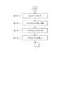
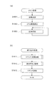
図5−1は、遊技制御部200による基本処理の動作を示すフローチャートである。
遊技制御部200は、パチンコ遊技機100の電源が投入されると、まず、RAM20
3(図3参照)へのアクセスを許可する(ステップ(以下、ステップを「S」と記載する
)101)。そして、遊技制御部200は、RAM203をクリアするためのRAMクリ
アスイッチがONとなっているか否かを判断する(S102)。
RAMクリアスイッチがOFFである場合(S102でNo)、次に、遊技制御部20
0は、電源遮断時の動作に関するバックアップフラグがONとなっているか否かを判断す
る(S103)。
バックアップフラグがONである場合(S103でYes)、次に、遊技制御部200
は、電源遮断時に作成されたチェックサムが正常か否かを判断する(S104)。
チェックサムが正常である場合(S104でYes)、次に、遊技制御部200は、復
帰処理を実行する(S105)。この復帰処理において、遊技制御部200は、電源が遮
断された状態からの復旧に伴う、演出制御部300等のサブ制御手段の設定を行う。具体
的には、遊技制御部200は、電源が遮断される際におけるパチンコ遊技機100の内部
状態(大当たり遊技中か否か、高確率状態と低確率状態のいずれか、時短状態と時短無状
態のいずれか)を反映させるように、サブ制御手段を設定するためのコマンドを演出制御
部300へ出力する。また、この復帰処理において、遊技制御部200は、バックアップ
フラグをOFFにする。
FIG. 5A is a flowchart illustrating an operation of basic processing by the
When the power of the
3 (see FIG. 3) is permitted (step (hereinafter, step is referred to as “S”) 101). Then, the
When the RAM clear switch is OFF (No in S102), next, the
In 0, it is determined whether or not the backup flag relating to the operation at the time of power-off is ON (S103).
If the backup flag is ON (Yes in S103), then the
Determines whether the checksum created at the time of power-off is normal (S104).
If the checksum is normal (Yes in S104), the
一方、RAMクリアスイッチがON(S102でYes)、バックアップフラグがOF
F(S103でNo)、チェックサムが異常(S104でNo)のいずれかに該当する場
合、次に遊技制御部200は、初期化処理として、RAM203の記憶内容をクリアし(
S106)、RAM203の作業領域を設定する(S107)。そして、遊技制御部20
0は、サブ制御手段を設定(初期化)するためのコマンドを演出制御部300へ出力し、
サブ基板(サブ制御手段)の設定を行う(S108)。サブ基板の設定には、各サブ基板
に搭載されているRAM303、313、323をクリアすること等が含まれる。
On the other hand, the RAM clear switch is ON (Yes in S102) and the backup flag is OF
F (No in S103), if the checksum is abnormal (No in S104), the
S106), the work area of the
0 outputs a command for setting (initializing) the sub-control means to the
The sub board (sub control means) is set (S108). The setting of the sub board includes clearing the
復帰処理(S105参照)が終了した後、またはサブ基板の設定(S108参照)が終
了した後、遊技制御部200は、遊技制御に用いられる各種のカウンタおよびタイマーを
設定する(S109)。そして、遊技制御部200は、割り込み許可(S110)、割り
込み禁止(S111)、図柄乱数制御処理(S112)、初期値乱数更新処理(S113
)、電源遮断フラグがONとなっているか否かの判断(S114)をループ処理として繰
り返し実行する。
ここで、割り込み許可(S110)および割り込み禁止(S111)は、このループ処
理(S110〜S114)の実行中に割り込み処理の実行を可能とするために設けられて
いる。本実施の形態では、この割り込み処理により、遊技制御における主制御処理が実行
される。主制御処理の詳細については後述する。
図柄乱数制御処理(S112)において、遊技制御部200は、特別図柄抽選で用いら
れる変動パターン乱数の更新を行う。
初期値乱数更新処理(S113)において、遊技制御部200は、遊技制御において用
いられる各種の乱数値の初期値を更新する。
電源遮断フラグの判断において、電源遮断フラグがOFFである場合(S114でNo
)、パチンコ遊技機100の電源は遮断されず、遊技制御部200は、ループ処理(S1
10〜S114)と共に割り込みによる主制御処理が繰り返し実行する。一方、電源遮断
フラグがONである場合(S114でYes)、遊技制御部200は、パチンコ遊技機1
00の電源を遮断するための処理(電源遮断時処理)を開始する。
After the return process (see S105) is completed or after the setting of the sub-board (see S108) is completed, the
), It is repeatedly executed as a loop process to determine whether or not the power shutoff flag is ON (S114).
Here, interrupt permission (S110) and interrupt prohibition (S111) are provided to enable execution of interrupt processing during execution of the loop processing (S110 to S114). In the present embodiment, main control processing in game control is executed by this interrupt processing. Details of the main control process will be described later.
In the symbol random number control process (S112), the
In the initial value random number update process (S113), the
In the determination of the power shutdown flag, if the power shutdown flag is OFF (No in S114)
), The power of the
10 to S114), the main control process by interruption is repeatedly executed. On the other hand, when the power-off flag is ON (Yes in S114), the
The process for shutting off the power of 00 (process when power is shut off) is started.
図5−2は、遊技制御部200による電源遮断時処理の動作を示すフローチャートであ
る。
電源遮断時処理において、遊技制御部200は、まず、各種の出力を行うための出力ポ
ートの設定をクリアする(S115)。次に、遊技制御部200は、チェックサムを作成
し、RAM203に格納する(S116)。次に、遊技制御部200は、バックアップフ
ラグをONにし(S117)、RAM203へのアクセスを禁止して(S118)、無限
ループに移行する。
FIG. 5B is a flowchart illustrating the operation of power-off processing by the
In the power-off process, the
〔遊技機の主制御処理〕
次に、パチンコ遊技機100の主制御処理を説明する。
遊技制御部200は、主制御処理において、パチンコ遊技機100における遊技を制御
すると共に、サブ制御手段である演出制御部300に対して演出の制御を指示し、払出制
御部330に対して賞球の払い出しの制御を指示する。
[Main control processing of gaming machines]
Next, main control processing of the
In the main control process, the
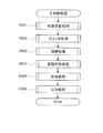
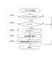
図5−3は、遊技制御部200の主制御処理の動作を示すフローチャートである。
主制御処理は、遊技制御における一連の処理からなり、予め設定された一定時間(例え
ば4ミリ秒)ごとに繰り返し実行される。本実施の形態において、遊技制御部200は、
予め設定された一定時間ごとに割り込みを発生させ、図5−1に示すループ処理の中で割
り込みが許可(S110参照)されると、割り込み処理として主制御処理を実行する。図
5−3に示すように、主制御処理では、乱数更新処理、スイッチ処理、図柄処理、電動役
物処理、賞球処理、出力処理が順次実行される(S501〜S506)。
FIG. 5-3 is a flowchart illustrating the operation of the main control process of the
The main control process includes a series of processes in game control, and is repeatedly executed at predetermined time intervals (for example, 4 milliseconds). In the present embodiment, the
When an interrupt is generated at predetermined time intervals and the interrupt is permitted in the loop process shown in FIG. 5A (see S110), the main control process is executed as the interrupt process. As shown in FIG. 5-3, in the main control process, a random number update process, a switch process, a symbol process, an electric accessory process, a prize ball process, and an output process are sequentially executed (S501 to S506).
乱数更新処理(S501)では、遊技制御部200は、乱数制御部241の機能(サブ
ルーチン)を呼び出し、遊技制御部200による遊技制御で用いられる各種の乱数の値を
更新する。乱数の設定および乱数値の更新の詳細については後述する。
In the random number update process (S501), the
スイッチ処理(S502)としては、始動口スイッチ処理、ゲートスイッチ処理が行わ
れる。
始動口スイッチ処理では、遊技制御部200は、乱数取得部231の機能(サブルーチ
ン)を呼び出し、図3の第1始動口スイッチ211および第2始動口スイッチ212の状
態を監視し、スイッチがONとなった場合に、特別図柄抽選のための処理を実行する。
ゲートスイッチ処理では、遊技制御部200は、乱数取得部231の機能(サブルーチ
ン)を呼び出し、図3のゲートスイッチ214の状態を監視し、スイッチがONとなった
場合に、普通図柄抽選のための処理を実行する。
これらのスイッチ処理の詳細な内容については後述する。
As the switch process (S502), a start port switch process and a gate switch process are performed.
In the start port switch process, the
In the gate switch process, the
Details of these switch processes will be described later.
図柄処理(S503)としては、特別図柄処理、普通図柄処理が行われる。
特別図柄処理では、遊技制御部200は、特別図柄変動制御部233、特別図柄判定部
234、変動パターン選択部235の各機能(サブルーチン)を呼び出し、特別図柄変動
およびこの図柄変動に伴う処理を実行する。
普通図柄処理では、遊技制御部200は、普通図柄変動制御部236および普通図柄判
定部232の機能(サブルーチン)を呼び出し、普通図柄変動およびこの図柄変動に伴う
処理を実行する。
これらの図柄処理の詳細な内容については後述する。
As the symbol processing (S503), special symbol processing and normal symbol processing are performed.
In the special symbol process, the
In the normal symbol process, the
The detailed contents of these symbol processes will be described later.
電動役物処理(S504)としては、大入賞口処理および電動チューリップ処理が行わ
れる。
大入賞口処理では、遊技制御部200は、大入賞口動作制御部237の機能(サブルー
チン)を呼び出し、所定の条件に基づいて特別電動役物である大入賞口125の開放動作
を制御する。
電動チューリップ処理では、遊技制御部200は、電動チューリップ動作制御部238
の機能(サブルーチン)を呼び出し、所定の条件に基づいて普通電動役物である電動チュ
ーリップ123の開放動作を制御する。
これらの電動役物処理の詳細な内容については後述する。
As the electric accessory process (S504), a big prize opening process and an electric tulip process are performed.
In the special prize opening process, the
In the electric tulip process, the
The function (subroutine) is called, and the opening operation of the electric tulip 123, which is a normal electric accessory, is controlled based on a predetermined condition.
The detailed contents of these electric accessory processing will be described later.
賞球処理(S505)では、遊技制御部200は、賞球処理部239の機能(サブルー
チン)を呼び出し、入賞個数の管理および入賞に応じた賞球の払い出しの制御用コマンド
をセットする。
In the prize ball processing (S505), the
出力処理(S506)では、遊技制御部200は、出力制御部240の機能(サブルー
チン)を呼び出し、演出制御用のコマンドを演出制御部300へ出力し、払い出し制御用
のコマンドを払出制御部330へ出力する。演出制御用コマンドは、S502からS50
4までの各処理において生成され、RAM203に設けられた制御用コマンドの格納領域
に格納(セット)される。払い出し制御用コマンドは、S505の処理において生成され
、RAM203に設けられた制御用コマンドの格納領域に格納(セット)される。RAM
203には、制御用コマンドの種類ごとに格納領域が設定されている。
In the output process (S506), the
4 is generated in each process up to 4, and is stored (set) in the storage area of the control command provided in the
In 203, a storage area is set for each type of control command.
出力制御部240は、出力処理(S506)においてRAM203の各制御用コマンド
の格納領域を順に調べ、個々の格納領域に制御用コマンドが格納されていれば(すなわち
、S502〜S505の処理で制御用コマンドが生成されていれば)、その制御用コマン
ドを読み出し、出力先(演出制御部300または払出制御部330)へ出力する。
The
本実施の形態では、図5−3に示したように、一連の主制御処理の最後に出力処理を行
う。すなわち、第1の処理手段としての上記各機能によるS502〜S505の各処理に
おいて生成されたコマンドを、その各処理においてはRAM203の対応する格納領域に
格納しておく。そして、これらの一連の処理の後に、第2の処理手段としての出力制御部
240が、RAM203の格納領域に蓄積された、各処理で生成されたコマンドをまとめ
て出力する。言い換えれば、本実施の形態では、主制御処理を1サイクル実行すると、そ
の1サイクルの実行において生成されたコマンドが、その1サイクルの実行における最後
のコマンド生成が行われた後に、出力される。
In the present embodiment, as shown in FIG. 5C, output processing is performed at the end of a series of main control processing. That is, the command generated in each process of S502 to S505 by the above functions as the first processing means is stored in a corresponding storage area of the
〔遊技制御部のRAMの構成例〕
特に図示しないが、RAM203には、上記の主制御処理で生成されたコマンドを、コ
マンドの種類ごとに格納するコマンド格納領域が設けられる。
また、詳しくは後述するが、遊技制御部200から演出制御部300へ送られるコマン
ドは、例えば、コマンドの種類を示すコードと、コマンドの内容を示すデータとを含む2
バイトの情報であり、主に1バイトでコードを記述し、他の1バイトでデータを記述して
いる。コードは、例えば、特別図柄抽選や普通図柄抽選に関する停止図柄、変動パターン
、保留、事前判定、大入賞口125や電動チューリップ123の作動指示、パチンコ遊技
機100の動作に関わるエラーの報知等の情報の種類を特定する。データは、コードによ
り特定された情報の具体的な内容を特定する。例えば、特別図柄抽選における停止図柄の
種類、選択された変動パターン、保留数等の情報や、大入賞口125の作動の具体的内容
(開放または閉鎖)、エラー報知の開始または終了の指示等が記述される。
[Configuration example of RAM of game control unit]
Although not particularly illustrated, the
As will be described in detail later, the command sent from the
This is byte information, in which a code is mainly described by 1 byte and data is described by another 1 byte. The code is, for example, information such as a special symbol lottery or a stop symbol related to a normal symbol lottery, a variation pattern, a hold, a preliminary determination, an operation instruction for the
上述したRAM203の各コマンド格納領域には、1つのコマンド格納領域に対して一
種類または複数種類のコマンドが対応付けられている。そして、図5−3に示した主制御
処理において、遊技制御部200は、生成したコマンドを、そのコマンドに対応付けられ
ているコマンド格納領域に格納していく。
ここで、主制御処理では、1サイクルの処理が実行される度に、必ずしも全てのコマン
ドが生成される訳ではない。例えば、第1始動口121や第2始動口122への入賞がな
いときは、特別図柄抽選の停止図柄や変動パターンに関するコマンドは生成されない。ま
た、大入賞口125や電動チューリップ123の作動指示のコマンドは、これらの電動役
物を作動させるべきタイミングでなければ生成されない。また、エラーを報知するコマン
ドは、そもそもエラーが発生していなければ生成されない。
したがって、主制御処理の出力処理(図5−3のS506参照)が行われる際には、通
常、RAM203に設けられたコマンド格納領域のうち、いくつかのコマンド格納領域に
はコマンドが格納されており、他のコマンド格納領域にはコマンドが格納されていない状
態となる。
Each command storage area of the
Here, in the main control process, not every command is necessarily generated every time one cycle of the process is executed. For example, when there is no winning at the
Therefore, when the output process of the main control process (see S506 in FIG. 5-3) is performed, commands are usually stored in some command storage areas of the command storage area provided in the
〔出力制御部による出力処理〕
次に、出力制御部240による出力処理(図5−3のS506)について説明する。
遊技制御部200の出力制御部240は、まず、RAM203に設けられたコマンド格
納領域の1つに着目し、着目したコマンド格納領域にコマンドが格納されているか否かを
調べる。そして、コマンドが格納されているならば、出力制御部240は、格納されてい
るコマンドを読み出して演出制御部300へ出力する。
[Output processing by output controller]
Next, output processing (S506 in FIG. 5-3) by the
First, the
着目したコマンド格納領域にコマンドが格納されていなかった場合、コマンド格納領域
に格納されていたコマンドを出力した後、出力制御部240は、未処理のコマンド格納領
域が有るか否かを調べる。未処理のコマンド格納領域が有る場合、出力制御部240は、
未処理のコマンド格納領域の1つに着目し、着目したコマンド格納領域に対するコマンド
の有無の確認、出力を繰り返す。
そして、全てのコマンド格納領域に対して処理を行ったならば、出力処理を終了する。
If no command is stored in the focused command storage area, the
Focusing on one of the unprocessed command storage areas, the confirmation and output of the presence / absence of a command in the focused command storage area are repeated.
Then, when processing has been performed for all command storage areas, the output processing is terminated.
以上のように、本実施の形態では、主制御処理を1サイクル実行した際に、その際のパ
チンコ遊技機100の状況に応じてコマンドが生成され、生成されたコマンドはRAM2
03のコマンド格納領域に格納される。そして、1サイクルの主制御処理の最後に、その
1サイクルの実行で生成されたコマンドをまとめてRAM203のコマンド格納領域から
読み出し、出力する。
As described above, in this embodiment, when one cycle of the main control process is executed, a command is generated according to the situation of the
03 is stored in the command storage area. At the end of one cycle of the main control process, the commands generated by the execution of the one cycle are collectively read from the command storage area of the
このような構成としたことにより、主制御処理においては、生成したコマンドを出力す
るためには、出力制御部240の機能を1回呼び出すだけで良い。すなわち、コマンドを
生成する度に、生成したコマンドを出力する機能(サブルーチン)を用意する必要がない
ため、制御命令の数を削減し、出力処理に関するプログラムのサイズの増大を抑制するこ
とができる。また、コマンドを生成する度に、生成したコマンドを出力する機能を呼び出
す必要がないため、出力処理全体に要する時間を短縮することができる。
With this configuration, in the main control process, in order to output the generated command, it is only necessary to call the function of the
〔遊技機の基本動作の変形例〕
なお、図5−1乃至図5−3を参照して説明した動作例では、基本処理におけるループ
処理の部分で割り込みを許可し、割り込み処理として一連の処理からなる主制御処理を実
行した。しかしながら、主制御処理は、一定時間ごとに繰り返し実行されるように構成さ
れていれば良く、具体的な実現手段(実行手順)は、図5−1乃至図5−3に示した例に
は限定されない。例えば、基本処理の一連の動作の中に主制御処理を組み入れておき、所
定のタイミングで経過時間を計測し、一定時間(例えば4ミリ秒)ごとに主制御処理へ戻
る構成としても良い。また、基本処理の一連の動作の中に主制御処理を組み入れる一方で
、図5−1乃至図5−3を参照して説明した動作と同様に、一定時間ごとに割り込みを発
生させ、割り込みが発生したならば基本処理中に組み入れられた主制御処理へ戻る構成と
しても良い。
[Modified example of basic operation of gaming machine]
In the operation example described with reference to FIGS. 5A to 5C, the interrupt is permitted in the loop process portion of the basic process, and the main control process including a series of processes is executed as the interrupt process. However, the main control process only needs to be configured to be repeatedly executed at regular intervals, and specific implementation means (execution procedure) is not limited to the examples shown in FIGS. It is not limited. For example, the main control process may be incorporated in a series of operations of the basic process, the elapsed time may be measured at a predetermined timing, and the process may return to the main control process every predetermined time (for example, 4 milliseconds). In addition, while incorporating the main control process in the series of operations of the basic process, as in the operation described with reference to FIG. 5A to FIG. If it occurs, it may be configured to return to the main control process incorporated in the basic process.
また、基本処理で生成されたコマンドを出力する場合は、原則として、コマンドを生成
する度に、RAM203のコマンド格納領域に格納し、主制御処理における第2の処理手
段である出力制御部240の機能を呼び出して出力する。基本処理は、電源投入時に行わ
れる初期動作等の特別処理であり、電源投入時のパチンコ遊技機100の状態等の条件に
基づく分岐により処理手順が変動する場合があるため、出力処理に漏れが無いように、生
成したコマンドを速やかに出力するためである。なお、関連する複数の処理により連続的
にコマンドが生成される場合等、具体的な処理の要請に応じて、複数のコマンドをRAM
203のコマンド格納領域に格納し、まとめて出力する処理手順を採っても良い。
When a command generated in the basic process is output, in principle, every time a command is generated, the command is stored in the command storage area of the
A processing procedure in which the command is stored in the
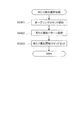
〔遊技制御部による乱数更新処理〕
特別図柄抽選等の遊技制御における各種の抽選に用いられる判定情報としての乱数値は
、カウンタによって計数され、所定の初期値から始まって、図5−3に示す主制御処理の
乱数更新処理(S501)が行われるたびに1ずつ加算される。そして、各抽選が行われ
た時点の値が始動口スイッチ処理(図6)およびゲートスイッチ処理(図7)で取得され
、特別図柄処理(図8)や普通図柄処理(図13)で使用される。この乱数値のカウンタ
は無限ループカウンタであり、計数された乱数値が、設定されている乱数の最大値(例え
ば、後述する図17(a)に示した大当たり乱数では299)に達した後は、再び初期値
に戻る。また、乱数更新処理は一定時間ごとに行われるため、各乱数の初期値が特定され
てしまうと、更新間隔や初期値の情報に基づいて当選値が推定される恐れがある。そこで
、主制御処理から図5−1に示す基本処理に戻った後、S113の初期値乱数更新処理に
おいて、各乱数の初期値をランダムに変更する。
[Random number update processing by game control unit]
A random number value as determination information used for various lotteries in game control such as special symbol lottery is counted by a counter and starts from a predetermined initial value, and is updated by a random number update process (S501) of the main control process shown in FIG. ) Is incremented by one each time. Then, the values at the time each lottery is performed are acquired by the start opening switch process (FIG. 6) and the gate switch process (FIG. 7), and used in the special symbol process (FIG. 8) and the normal symbol process (FIG. 13). The This random number counter is an infinite loop counter, and after the counted random number value reaches the set random number maximum value (for example, 299 for the jackpot random number shown in FIG. 17A to be described later) Return to the initial value again. In addition, since the random number update process is performed at regular intervals, if the initial value of each random number is specified, the winning value may be estimated based on the update interval and the initial value information. Therefore, after returning from the main control process to the basic process shown in FIG. 5A, the initial value of each random number is randomly changed in the initial value random number update process of S113.
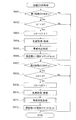
〔遊技制御部による始動口スイッチ処理〕
図6は、図5−3のS502に示したスイッチ処理のうちの始動口スイッチ処理の内容
を示すフローチャートである。
この始動口スイッチ処理は、第1始動口121における入賞に対する処理と、第2始動
口122における入賞に対する処理とが順次行われる。図6を参照すると、遊技制御部2
00は、まず、第1始動口121に遊技球が入賞して第1始動口スイッチ211がONと
なったか否かを判断する(S601)。第1始動口スイッチ211がONとなったならば
、次に遊技制御部200は、第1始動口121の入賞における未変動分の保留数U1が上
限値未満か否かを判断する(S602)。図6に示す例では、上限値を4個としている。
保留数U1が上限値に達している場合は(S602でNo)、それ以上未変動分の入賞を
保留することができないので、第1始動口121における入賞に対する処理を終了する。
[Start-up switch processing by game control unit]
FIG. 6 is a flowchart showing the contents of the start port switch process in the switch process shown in S502 of FIG. 5-3.
In the start port switch process, a process for winning at the
In 00, first, it is determined whether or not a game ball is won at the
If the number of holds U1 has reached the upper limit (No in S602), it is not possible to hold any more unchanging winnings, so the process for winning at the
一方、保留数U1が上限値未満である場合(S602でYes)、次に遊技制御部20
0は、保留数U1の値を1加算する(S603)。そして、遊技制御部200の乱数取得
部231は、今回の入賞による抽選のための乱数値を取得し、RAM203に設定された
所定の格納領域に格納する(S604)。ここでは、第1始動口121の入賞なので、特
別図柄抽選のための乱数値が取得される。このとき取得される乱数値は、先行するS50
1の乱数更新処理で更新された値である。そして、この乱数値により、後の特別図柄処理
において特別図柄抽選の結果が確定される。ここにいう乱数値としては、大当たり、小当
たりまたははずれを決定する大当たり乱数値、大当たりの種類(大当たり遊技の終了後に
おける時短状態か時短無状態、高確率状態と低確率状態、長当たり、短当たり)を決定す
る図柄乱数値(大当たり図柄乱数値)、図柄変動における変動パターンを特定するための
変動パターン乱数値、はずれのときにリーチ有り演出をするか否かを決定するリーチ乱数
値、等が含まれる。
On the other hand, when the holding number U1 is less than the upper limit value (Yes in S602), next, the
0 adds 1 to the value of the holding number U1 (S603). Then, the random
1 is a value updated by random number update processing of 1. Then, the result of the special symbol lottery is determined in the later special symbol processing by this random number value. Random numbers here include jackpot random numbers that determine jackpot, jackpot or loss, jackpot type (short or short state after the end of jackpot game, short or short state, high probability state and low probability state, long hit, short Symbol random number value that determines the winning pattern, jackpot symbol random number value, fluctuation pattern random number value for specifying the variation pattern in symbol variation, reach random number value that determines whether or not to perform with reach in the event of a loss, etc. Is included.
次に、遊技制御部200は、特別図柄の変動表示動作が保留されている(すなわち未抽
選の)入賞球(保留球)に対して、抽選結果の予告演出を行うための事前判定処理を行う
(S605)。この事前判定処理は、抽選結果の判定を図柄変動開始時ではなく始動口入
賞時に(すなわちS605において)行うものである。なお、事前判定に基づく予告演出
を行わない遊技機においては、この事前判定処理を省略する場合がある。
この後、遊技制御部200は、S603による保留数U1の増加を演出制御部300に
通知するための保留数増加コマンドをRAM203に設定された制御コマンド用の所定の
格納領域にセットし(S606)、第1始動口121における入賞に対する処理を終了す
る。S605の事前判定処理が行われた場合は、保留数増加コマンドには、S605で得
られた事前判定の判定結果の情報が含まれる。
Next, the
Thereafter, the
次に、第2始動口122における入賞に対する処理が行われる。図6を参照すると、次
に遊技制御部200は、第2始動口122に遊技球が入賞して第2始動口スイッチ212
がONとなったか否かを判断する(S607)。第2始動口スイッチ212がONとなっ
たならば、次に遊技制御部200は、第2始動口122の入賞における未変動分の保留数
U2が上限値未満か否かを判断する(S608)。図6に示す例では、上限値を4個とし
ている。保留数U2が上限値に達している場合は(S608でNo)、それ以上未変動分
の入賞を保留することができないので、第2始動口122における入賞に対する処理を終
了する。
Next, a process for winning in the second start port 122 is performed. Referring to FIG. 6, the
It is determined whether or not is turned on (S607). If the second
一方、保留数U2が上限値未満である場合(S608でYes)、次に遊技制御部20
0は、保留数U2の値を1加算する(S609)。そして、遊技制御部200の乱数取得
部231は、今回の入賞による抽選のための乱数値を取得し、RAM203に設定された
所定の格納領域に格納する(S610)。ここでは、第2始動口122の入賞なので、上
記のS604と同様に、特別図柄抽選のための乱数値(大当たり乱数値、大当たり図柄乱
数値)、リーチ乱数値、変動パターン乱数値など)が取得される。このとき取得される乱
数値は、S501の乱数更新処理で更新された値である。そして、この乱数値により後の
特別図柄処理において特別図柄抽選の結果が確定される。
On the other hand, when the holding number U2 is less than the upper limit value (Yes in S608), next, the
0 adds 1 to the value of the holding number U2 (S609). Then, the random
次に、遊技制御部200は、特別図柄の変動表示動作が保留されている(すなわち未抽
選の)入賞球(保留球)に対して、抽選結果の予告演出を行うための事前判定処理を行う
(S611)。この事前判定処理の内容は、上記のS605と同様である。この事前判定
処理も、事前判定に基づく予告演出を行わない遊技機においては、この事前判定処理を省
略する場合がある。
この後、遊技制御部200は、S609による保留数U2の増加を演出制御部300に
通知するための保留数増加コマンドをRAM203に設定された制御コマンド用の所定の
格納領域にセットし(S612)、第2始動口122における入賞に対する処理を終了す
る。S611の事前判定処理が行われた場合は、保留数増加コマンドには、S611で得
られた事前判定の判定結果の情報が含まれる。
Next, the
Thereafter, the
〔遊技制御部によるゲートスイッチ処理〕
図7は、ゲート124を遊技球が通過した場合のゲートスイッチ処理の内容を示すフロ
ーチャートである。
このゲートスイッチ処理において、遊技制御部200は、まず、ゲート124を遊技球
が通過してゲートスイッチ214がONとなったか否かを判断する(S701)。ゲート
スイッチ214がONとなったならば、次に遊技制御部200は、未変動分の保留数Gが
上限値未満か否かを判断する(S702)。図7に示す例では、上限値を4個としている
。保留数Gが上限値に達している場合は(S702でNo)、それ以上未変動分の入賞を
保留することができないので、ゲートスイッチ処理を終了する。
[Gate switch processing by game control unit]
FIG. 7 is a flowchart showing the contents of the gate switch process when a game ball passes through the
In this gate switch process, the
一方、保留数Gが上限値未満である場合(S702でYes)、次に遊技制御部200
は、保留数Gの値を1加算する(S703)。そして、遊技制御部200の乱数取得部2
31は、今回の入賞による抽選のための乱数値を取得し、RAM203に設定された所定
の格納領域に格納する(S704)。ここでは、ゲート124の入賞なので、普通図柄抽
選のための乱数値(当たり乱数値など)が取得される。
On the other hand, when the number G of holding is less than the upper limit value (Yes in S702), next, the
Adds 1 to the value of the holding number G (S703). And the random
31 obtains a random number value for the lottery by the current winning and stores it in a predetermined storage area set in the RAM 203 (S704). Here, since the
S704で乱数値が取得された後、遊技制御部200は、S703による保留数Gの増
加を演出制御部300に通知するための保留数G増加コマンドをRAM203に設定され
た制御コマンド用の所定の格納領域にセットし(S705)、ゲート124における入賞
に対する処理を終了する。
After the random number value is acquired in S704, the
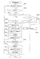
〔遊技制御部による特別図柄処理〕
図8は、図5−3のS503に示した図柄処理のうちの特別図柄処理の内容を示すフロ
ーチャートである。
この特別図柄処理において、遊技制御部200の特別図柄変動制御部233は、まず、
RAM203においてセットされるフラグの設定(以下、フラグ設定)において当たり遊
技フラグがONになっているか否かを調べる(S801)。ここで、当たり遊技フラグは
、パチンコ遊技機100が大当たり遊技中であることを識別するためにセットされるフラ
グである。実行中の大当たり遊技の種類に応じて、長当たり遊技フラグ、短当たり遊技フ
ラグのいずれかがセットされる。本実施の形態では、これらを総称して当たり遊技フラグ
と呼ぶ。
[Special symbol processing by game control unit]
FIG. 8 is a flowchart showing the contents of the special symbol processing in the symbol processing shown in S503 of FIG. 5-3.
In this special symbol processing, the special symbol
In the setting of the flag set in the RAM 203 (hereinafter, flag setting), it is checked whether or not the winning game flag is ON (S801). Here, the winning game flag is a flag that is set to identify that the
当たり遊技フラグがONである場合、既にパチンコ遊技機100は大当たり遊技中であ
るので、特別図柄変動を開始することなく特別図柄処理を終了する(S801でYes)
。一方、当たり遊技フラグがOFFである場合(S801でNo)、次に特別図柄変動制
御部233は、パチンコ遊技機100の現在の状態が特別図柄変動中か否かを判断する(
S802)。特別図柄変動中でない場合(S802でNo)、次に特別図柄変動制御部2
33は、特別図柄の未変動分の保留数U1、U2(図6参照)に関する処理を行う(S8
03〜S806)。本実施の形態では、第1始動口121の入賞に係る保留数U1と第2
始動口122の入賞に係る保留数U2とを区別しているので、この処理も対応する始動口
ごとに個別に行う。
When the winning game flag is ON, since the
. On the other hand, if the winning game flag is OFF (No in S801), then the special symbol
S802). If the special symbol is not changing (No in S802), then the special symbol
33 performs a process related to the number of holdings U1 and U2 (see FIG. 6) for the unchanging special symbol (S8).
03-S806). In the present embodiment, the holding number U1 and the second number related to winning of the
Since the number of holds U2 related to winning at the start port 122 is distinguished, this processing is also performed for each corresponding start port.
具体的には、特別図柄変動制御部233は、まず第2始動口122の入賞に係る保留数
U2が1以上か判断する(S803)。保留数U2が1以上である場合(S803でYe
s)、特別図柄変動制御部233は、保留数U2の値を1減算する(S804)。一方、
保留数U2=0である場合は(S803でNo)、特別図柄変動制御部233は、次に第
1始動口121の入賞に係る保留数U1が1以上か判断する(S805)。保留数U1が
1以上である場合(S805でYes)、特別図柄変動制御部233は、保留数U1の値
を1減算する(S806)。一方、保留数U1=0である場合は(S805でNo)、特
別図柄の抽選を始動するための入賞が無いことを意味するため、特別図柄変動を開始せず
、別ルーチンの客待ち設定処理を実行して処理を終了する(S816)。
なお、本実施の形態では、第2始動口122の入賞に係る保留数U2に関する処理を優
先させて行った。すなわち、保留数U2が1以上である場合は保留数U2に関する処理を
行い、保留数U2=0である場合に保留数U1に関する処理を行っている(S803〜S
806参照)。これに対し、第1始動口121と第2始動口122のどちらの入賞かに関
わらず、例えば入賞した順に保留数U1、U2を減算していくような制御とすることも可
能である。
Specifically, the special symbol
s), the special symbol
When the number of holdings U2 = 0 (No in S803), the special symbol
In the present embodiment, priority is given to the processing related to the holding number U2 related to winning in the second start port 122. That is, when the number of holds U2 is 1 or more, the process related to the number of holds U2 is performed, and when the number of holds U2 = 0, the process related to the number of holds U1 is performed (S803 to S3).
806). On the other hand, regardless of which of the
S804またはS806で保留数U1または保留数U2を減算した後、特別図柄変動制
御部233は、RAM203のフラグ設定においてセットされた客待ちフラグをOFFと
する(S807)。客待ちフラグは、パチンコ遊技機100が客待ち状態であることを識
別するためのフラグであり、客待ち設定処理(S816、図12参照)においてセットさ
れる。
After subtracting the reserved number U1 or the reserved number U2 in S804 or S806, the special symbol
次に、特別図柄変動制御部233は、別ルーチンによる大当たり判定処理および変動パ
ターン選択処理を実行する(S808、S809)。詳しくは後述するが、この大当たり
判定処理および変動パターン選択処理によって、第1特別図柄表示器221、第2特別図
柄表示器222に変動表示される特別図柄の変動用の設定情報(大当たり図柄、遊技状態
、変動パターン等)が決定される。なお、これらの情報は演出制御部300に送られる変
動開始コマンドに含まれる。
Next, the special symbol
この後、特別図柄変動制御部233は、大当たり判定処理および変動パターン選択処理
で決定された設定内容に基づき、図2に示す第1特別図柄表示器221、第2特別図柄表
示器222により表示される特別図柄の変動を開始する(S810)。そして、この設定
内容を示す設定情報(大当たり図柄、遊技状態、変動パターン等)を含んだ変動開始コマ
ンドを生成し、RAM203に設定された制御コマンド用の所定の格納領域にセットする
(S811)。S811でセットされた変動開始コマンドは、図5−3のS506に示し
た出力処理で演出制御部300へ送信される。
Thereafter, the special symbol
S802で特別図柄変動中と判断された場合(S802でYes)、またはS811で
変動開始コマンドがセットされた後、特別図柄変動制御部233は、変動時間を経過した
か否かを判断する(S812)。すなわち、S810で特別図柄の変動を開始してからの
経過時間がS809の変動パターン選択処理で設定された変動時間に達したか否かが判断
される。変動時間を経過していなければ(S812でNo)、特別図柄変動が継続される
ので、そのまま特別図柄処理が終了する。
When it is determined in S802 that the special symbol is changing (Yes in S802), or after the change start command is set in S811, the special symbol
一方、変動時間を経過した場合(S812でYes)、特別図柄変動制御部233は、
まず、第1特別図柄表示器221、第2特別図柄表示器222における特別図柄の変動を
S808の大当たり判定処理で決定された図柄で停止する(S813)。後述する装飾図
柄を停止させるための変動停止コマンドをRAM203に設定された制御コマンド用の所
定の格納領域にセットする(S814)。そして、別ルーチンの停止中処理を実行する(
S815)。停止中処理の内容については後述する。S814でセットされた変動停止コ
マンドは、図5−3のS506に示した出力処理で演出制御部300へ送信される。
On the other hand, when the variation time has elapsed (Yes in S812), the special symbol
First, the variation of the special symbols in the first
S815). The contents of the stop process will be described later. The change stop command set in S814 is transmitted to the
〔遊技制御部による大当たり判定処理〕
図9は、大当たり判定処理(図8のS808)の内容を示すフローチャートである。
この大当たり判定処理において、遊技制御部200の特別図柄判定部234は、まず、
今回の特別図柄抽選における大当たり乱数値の判定を行い(S901)、大当たりまたは
小当たりしたか否かを判断する(S902、S905)。大当たりまたは小当たりしたか
否かは、図6のS604またはS610で取得した大当たり乱数の値が、大当たりの当選
値として設定された値または小当たりの当選値として設定された値と一致したか否かを判
断することによって決定される(図17(a)参照)。
[Big hit judgment processing by game control unit]
FIG. 9 is a flowchart showing the contents of the jackpot determination process (S808 in FIG. 8).
In this jackpot determination process, the special
In this special symbol lottery, the jackpot random number is determined (S901), and it is determined whether the jackpot or the jackpot has been won (S902, S905). Whether or not the jackpot or the jackpot is determined is whether or not the value of the jackpot random number acquired in S604 or S610 in FIG. 6 matches the value set as the jackpot winning value or the value set as the jackpot winning value It is determined by judging whether or not (see FIG. 17A).
S901の乱数判定の結果が大当たりだった場合(S902でYes)、次に特別図柄
判定部234は、大当たり図柄乱数値の判定を行う(S903)。この判定の結果に応じ
て、大当たりの種類(高確率状態か低確率状態、時短状態か時短無状態、長当たり、短当
たり)が決定される。いずれの大当たりとなるかは、図6のS604またはS610で取
得した大当たり図柄乱数の値が、大当たりの種類ごとに予め設定された値のうちのいずれ
と一致したかによって決定される(図17(b)参照)。
If the result of the random number determination in S901 is a big hit (Yes in S902), then the special
以上の判定の後、特別図柄判定部234は、大当たり図柄乱数の判定により決定された
大当たりの種類を表す図柄(大当たり図柄)を設定情報としてRAM203に設定された
所定の格納領域にセットする(S904)。
After the above determination, the special
S901の乱数判定の結果が小当たりだった場合(S902でNo、S905でYes
)、次に特別図柄判定部234は、小当たりであることを表す図柄(以下、小当たり図柄
)を設定情報としてRAM203に設定された所定の格納領域にセットする(S906)
。
When the result of random number determination in S901 is a small hit (No in S902, Yes in S905)
Then, the special
.
S901の乱数判定の結果が大当たりでも小当たりでもない場合(S902、S905
でNo)、次に特別図柄判定部234は、抽選にはずれたことを表す図柄(以下、はずれ
図柄)を設定情報としてRAM203に設定された所定の格納領域にセットする(S90
7)。
When the result of the random number determination in S901 is neither big win nor small win (S902, S905)
Next, the special
7).
〔遊技制御部による変動パターン選択処理〕
図10は、変動パターン選択処理(図8のS809)の内容を示すフローチャートであ
る。
この変動パターン選択処理において、遊技制御部200の変動パターン選択部235は
、まず、大当たり判定処理(図9)のS902の判断結果を用いて今回の特別図柄抽選で
大当たりしたか否かを判断する(S1001)。そして、大当たりだった場合(S100
1でYes)、変動パターン選択部235は、大当たり用の変動パターンテーブルをRO
M202から読み出してRAM203に設定された所定の格納領域にセットする(S10
02)。
[Change pattern selection process by game control unit]
FIG. 10 is a flowchart showing the contents of the variation pattern selection process (S809 in FIG. 8).
In this variation pattern selection process, the variation
1), the fluctuation
The data is read from M202 and set in a predetermined storage area set in the RAM 203 (S10).
02).
一方、大当たりしなかった場合(S1001でNo)、次に変動パターン選択部235
は、遊技者に大当たりを期待させるためのいわゆるリーチ演出を行うか否かを決定するた
めの乱数値の判定を行う(S1003)。リーチ演出を行うか否かは、図6のS604ま
たはS610で取得したリーチ乱数の値が予め設定された値と一致したか否かを判断する
ことによって決定される(図17(c)参照)。
乱数値を用いた判定の結果、リーチ演出を行う場合(S1004でYes)、変動パタ
ーン選択部235は、リーチ用の変動パターンテーブルをROM202から読み出してR
AM203に設定された所定の格納領域にセットする(S1005)。また、リーチ演出
を行わない場合(S1004でNo)、変動パターン選択部235は、はずれ用の変動パ
ターンテーブルをROM202から読み出してRAM203に設定された所定の格納領域
にセットする(S1006)。
ここで、変動パターンテーブルとは、予め用意されている複数の変動パターン(変動時
間10秒、30秒、60秒、90秒など)と変動パターン乱数の値とを対応付けたテーブ
ルである(図18参照)。
On the other hand, if it is not a big hit (No in S1001), then the variation
Determines a random number value to determine whether or not to perform a so-called reach effect for causing the player to expect a big hit (S1003). Whether or not the reach effect is performed is determined by determining whether or not the reach random number value acquired in S604 or S610 in FIG. 6 matches a preset value (see FIG. 17C). .
As a result of the determination using the random number value, when the reach effect is performed (Yes in S1004), the variation
The predetermined storage area set in the
Here, the variation pattern table is a table in which a plurality of variation patterns (variation times of 10 seconds, 30 seconds, 60 seconds, 90 seconds, etc.) prepared in advance are associated with values of variation pattern random numbers (see FIG. 18).
次に、変動パターン選択部235は、図6のS604またはS610で取得した変動パ
ターン乱数値およびS1002、S1005、S1006でセットされた変動パターンテ
ーブルを用いて、変動パターン乱数値の判定を行う(S1007)。すなわち、変動パタ
ーン選択部235は、RAM203にセットされた変動パターンテーブルを参照し、変動
パターン乱数の乱数値に応じた変動パターンを選択する。したがって、同じ乱数値が取得
された場合でも、特別図柄抽選の結果が、大当たりしたか否か、大当たりしていない場合
はリーチ演出を行うか否か、といった状態の違いに応じて参照される変動パターンテーブ
ルが異なるので、決定される変動パターンが異なる。
Next, the variation
この後、変動パターン選択部235は、S1007で選択した変動パターンを設定情報
としてRAM203に設定された所定の格納領域にセットする(S1008)。S100
8でセットされた変動パターンの設定情報は、図8のS811でセットされる変動開始コ
マンドに含まれ、図5−3のS506に示した出力処理で演出制御部300へ送信される
。本実施の形態で選択される変動パターンおよびその設定の詳細については後述する。
Thereafter, the fluctuation
The variation pattern setting information set in 8 is included in the variation start command set in S811 of FIG. 8, and is transmitted to the
〔遊技制御部による停止中処理〕
図11は、停止中処理(図8のS815)の内容を示すフローチャートである。
この停止中処理において、遊技制御部200は、まず、RAM203のフラグ設定にお
いて時短状態であることを示すフラグ(以下、時短フラグ)がONになっているか否かを
調べる(S1101)。時短フラグがONである場合(S1101でYes)、遊技制御
部200は、時短状態での抽選回数(変動回数)Jの値を1減算し(S1102)、抽選
回数Jが0になったか否かを調べる(S1103)。そして、抽選回数J=0であれば(
S1103でYes)、時短フラグをOFFにする(S1104)。なお、時短フラグを
ONにする操作と、抽選回数Jの初期値の設定は、後述の大入賞口処理(図14)におけ
る遊技状態設定処理(図15)で行われる。
[Processing during stop by game control unit]
FIG. 11 is a flowchart showing the contents of the suspension process (S815 in FIG. 8).
In the stop process, the
If YES in S1103), the time reduction flag is turned OFF (S1104). It should be noted that the operation for turning on the hourly flag and the setting of the initial value of the lottery number J are performed in a game state setting process (FIG. 15) in a special winning opening process (FIG. 14) described later.
時短フラグがOFFであった場合(S1101でNo)またはS1104で時短フラグ
をOFFにした後、あるいはS1102で減算した後の抽選回数Jの値が0でない場合(
S1103でNo)、次に遊技制御部200は、RAM203のフラグ設定において高確
率状態であることを示すフラグ(以下、確変フラグ)がONになっているか否かを調べる
(S1105)。なお、この確変フラグと先の時短フラグが共にONである場合は、高確
率時短遊技状態であり、確変フラグがONであり時短フラグがOFFである場合は、高確
率時短無遊技状態である。
When the time reduction flag is OFF (No in S1101), or after the time reduction flag is turned OFF in S1104, or when the value of the number of lotteries J after subtraction in S1102 is not 0 (
Next, the
確変フラグがONである場合(S1105でYes)、遊技制御部200は、高確率状
態での抽選回数(変動回数)Xの値を1減算し(S1106)、抽選回数Xが0になった
か否かを調べる(S1107)。そして、抽選回数X=0であれば(S1107でYes
)、確変フラグをOFFにする(S1108)。なお、確変フラグをONにする操作と、
抽選回数Xの初期値の設定は、後述の大入賞口処理(図14)における遊技状態設定処理
(図15)で行われる。
When the probability variation flag is ON (Yes in S1105), the
), The probability variation flag is turned OFF (S1108). An operation to turn on the probability variation flag,
The initial value of the lottery number X is set in a game state setting process (FIG. 15) in a special prize opening process (FIG. 14) described later.
確変フラグがOFFであった場合(S1105でNo)またはS1108で確変フラグ
をOFFにした後、あるいはS1106で減算した後の抽選回数Xの値が0でない場合(
S1107でNo)、次に遊技制御部200は、今回の特別図柄抽選で大当たりしたか否
かを判断する(S1109)。そして、大当たりだった場合(S1109でYes)、次
に遊技制御部200は、大当たりの種類が長当たりか否かを判断する(S1110)。
When the probability variation flag is OFF (No in S1105), or after the probability variation flag is turned OFF in S1108, or when the value of the lottery count X after subtraction in S1106 is not 0 (
Next, in step S1107, the
ここで、大当たりか否かの判断は、大当たり判定処理(図9)の判定結果に基づいて判
断することができる。例えば、後述する図17(b)の図表に示す図柄のいずれかがセッ
トされているならば、S1109でYesである。大当たり判定処理によりRAM203
に、はずれ図柄または小当たり図柄がセットされているならば、S1109でNoである
。
Here, the determination of whether or not the jackpot is possible can be made based on the determination result of the jackpot determination process (FIG. 9). For example, if any of the symbols shown in the diagram of FIG.
In addition, if the off symbol or the small hit symbol is set, No in S1109.
大当たりの種類が長当たりであった場合(S1110でYes)、遊技制御部200は
、長当たり遊技フラグをONにする(S1111)。これにより、RAM203の遊技状
態の設定が、大当たりの種類が長当たりである大当たり遊技状態(長当たり遊技状態)と
なる。なお、ここでは長当たりにおいて、高確率状態か低確率状態かを区別していない。
高確率状態となるか低確率状態となるかは、後述の大入賞口処理(図14)における遊技
状態設定処理(図15)で該当するフラグをONにすることによって特定される。
When the jackpot type is a long hit (Yes in S1110), the
Whether the state is a high probability state or a low probability state is specified by turning on a corresponding flag in a game state setting process (FIG. 15) in a special prize opening process (FIG. 14) described later.
大当たりの種類が長当たりでなかった場合(S1110でNo)、遊技制御部200は
、短当たり遊技フラグをONにする(S1112)。これにより、RAM203の遊技状
態の設定が、大当たりの種類が短当たりである大当たり遊技状態(短当たり遊技状態)と
なる。長当たりの場合と同様、短当たりの場合も高確率状態か低確率状態かを区別してい
ない。
If the jackpot type is not long hit (No in S1110), the
S1111またはS1112で当たり遊技フラグをONにした後、遊技制御部200は
、抽選回数J、Xの値を初期化する(S1113)。また、S1101において時短フラ
グがONであって、S1103において抽選回数Jが0でなかった場合、遊技制御部20
0は、時短フラグをOFFにする(S1114)。同様に、S1105において確変フラ
グがONであって、S1107において抽選回数Xが0でなかった場合、遊技制御部20
0は、確変フラグをOFFにする(S1114)。
After turning on the winning game flag in S1111 or S1112, the
0 turns off the time flag (S1114). Similarly, if the probability variation flag is ON in S1105 and the lottery count X is not 0 in S1107, the
0 turns off the probability variation flag (S1114).
S1113で抽選回数J、Xの値を初期化した後、遊技制御部200は、オープニング
動作を開始する(S1117)。ここで、オープニング動作の内容は、S1111、S1
112のいずれで当たり遊技フラグがONとなったかに応じて異なる。すなわち、当たり
遊技フラグの状態に応じて、長当たり遊技、短当たり遊技の各遊技状態において設定され
たオープニング動作のいずれかが行われることとなる。
この後、遊技制御部200は、演出制御部300において当たり遊技フラグに応じたオ
ープニング動作における演出を行うためのオープニングコマンドをRAM203に設定さ
れた制御コマンド用の所定の格納領域にセットして(S1118)、停止中処理を終了す
る。このオープニングコマンドは、図5−3のS506に示した出力処理で演出制御部3
00へ送信される。
After initializing the values of the lottery times J and X in S1113, the
It differs depending on which of 112 the winning game flag is turned on. That is, according to the state of the winning game flag, one of the opening operations set in each gaming state of the long winning game and the short winning game is performed.
Thereafter, the
To 00.
これに対し、今回の特別図柄抽選の結果が大当たりでなかった場合(S1109でNo
)、次に遊技制御部200は、今回の特別図柄抽選の結果が小当たりであったか否かを判
断する(S1115)。小当たりでなかった場合は(S1115でNo)、停止中処理を
終了する。
一方、小当たりであった場合(S1115でYes)、遊技制御部200は、小当たり
遊技を開始して、停止中処理を終了する(S1116)。これにより、RAM203の遊
技状態の設定が小当たり遊技状態となる。なお、小当たり遊技では、前述したように、大
入賞口125を所定回数開閉し、所定時間経過後に終了する。
On the other hand, if the result of this special symbol lottery is not a big hit (No in S1109)
Next, the
On the other hand, if it is a small hit (Yes in S1115), the
〔遊技制御部による客待ち設定処理〕
図12は、客待ち設定処理(図8のS816)の内容を示すフローチャートである。
この客待ち設定処理において、遊技制御部200は、まず、RAM203のフラグ設定
において客待ちフラグがONになっているか否かを調べる(S1201)。ここで、客待
ちフラグは、パチンコ遊技機100が客待ち状態であることを識別するためにセットされ
るフラグである。
[Customer waiting setting process by game control unit]
FIG. 12 is a flowchart showing the contents of the customer waiting setting process (S816 in FIG. 8).
In this customer waiting setting process, the
客待ちフラグがONである場合、パチンコ遊技機100は客待ち状態であるので、その
まま処理を終了する(S1201でYes)。一方、客待ちフラグがOFFである場合、
遊技制御部200は、客待ちコマンドを生成してRAM203に設定された制御コマンド
用の所定の格納領域にセットし(S1202)、客待ちフラグをONにする(S1203
)。S1202でセットされた客待ちコマンドは、図5−3のS506に示した出力処理
で演出制御部300へ送信される。なお、客待ちフラグは、特別図柄の変動が停止して、
保留が無い状態でセットされるフラグである(図8参照)。
If the customer waiting flag is ON, the
The
). The customer waiting command set in S1202 is transmitted to the
This flag is set when there is no hold (see FIG. 8).
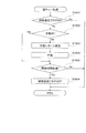
〔遊技制御部による普通図柄処理〕
図13は、図5−3のS503に示した図柄処理のうちの普通図柄処理の内容を示すフ
ローチャートである。
この普通図柄処理において、遊技制御部200の普通図柄変動制御部236は、まず、
RAM203のフラグ設定において補助遊技フラグがONになっているか否かを調べる(
S1301)。ここで、補助遊技フラグは、普通図柄抽選で当選した場合にセットされる
フラグである。補助遊技フラグが設定されている状態は、電動チューリップ123が後述
の電動チューリップ処理(図16)にしたがって開放され、第2始動口122に入賞し易
くなっている状態である(補助遊技状態)。
[Normal symbol processing by game control unit]
FIG. 13 is a flowchart showing the contents of the normal symbol processing in the symbol processing shown in S503 of FIG. 5-3.
In this normal symbol processing, the normal symbol
It is checked whether or not the auxiliary game flag is ON in the flag setting of the RAM 203 (
S1301). Here, the auxiliary game flag is a flag that is set when a normal symbol lottery is won. The state in which the auxiliary game flag is set is a state in which the electric tulip 123 is opened in accordance with the electric tulip process (FIG. 16) described later, and it is easy to win the second start port 122 (auxiliary game state).
補助遊技フラグがONである場合、既に補助遊技状態となっており、普通図柄が停止し
ている状態なので、普通図柄変動を開始することなく普通図柄処理を終了する(S130
1でYes)。一方、補助遊技フラグがOFFである場合(S1301でNo)、次に普
通図柄変動制御部236は、パチンコ遊技機100の現在の状態が普通図柄変動中か否か
を判断する(S1302)。普通図柄変動中でない場合(S1302でNo)、次に普通
図柄変動制御部236は、普通図柄の未変動分の保留数G(図7参照)が1以上か判断す
る(S1303)。保留数G=0である場合は(S1303でNo)、普通図柄の抽選を
始動するための入賞が無いことを意味するため、普通図柄変動を開始せずに処理を終了す
る。
When the auxiliary game flag is ON, since the auxiliary game state has already been reached and the normal symbol is stopped, the normal symbol processing is terminated without starting the normal symbol variation (S130).
1 is Yes). On the other hand, if the auxiliary game flag is OFF (No in S1301), then the normal symbol
これに対し、保留数Gが1以上である場合(S1303でYes)、普通図柄変動制御
部236は、保留数Gの値を1減算する(S1304)。そして、普通図柄判定部232
が、今回の普通図柄抽選における当たり乱数値の判定を行って、普通図柄抽選に当選した
か否かを判断する(S1305)。当選したか否かは、図7のS704で取得した当たり
乱数の値が、後述する図17(d)に示すテーブル等において当選値として設定された値
と一致したか否かを判断することによって決定される。なお、普通図柄抽選において複数
の種類の当たりが設定される場合、普通図柄判定部232は、例えば、S1304で当た
りと判定すると、次に当たりの種類に関する乱数値(当たり図柄乱数値)の判定を行って
当たりの種類を特定する。
On the other hand, when the reserved number G is 1 or more (Yes in S1303), the normal symbol
However, it is determined whether or not the normal symbol lottery is won by determining the winning random number value in the current normal symbol lottery (S1305). Whether or not the winner has been won is determined by determining whether or not the value of the winning random number acquired in S704 of FIG. 7 matches the value set as the winning value in the table shown in FIG. It is determined. When a plurality of types of hits are set in the normal symbol lottery, for example, if the normal
次に、普通図柄変動制御部236は、普通図柄抽選の結果に応じて普通図柄の設定を行
う(S1306)。すなわち、普通図柄抽選に当選した場合は、当選したことを表す図柄
(以下、当たり図柄)を設定情報としてRAM203に設定された所定の格納領域にセッ
トする。一方、普通図柄抽選に当選しなかった場合は、抽選にはずれたことを表す図柄(
以下、はずれ図柄)を設定情報としてRAM203に設定された所定の格納領域にセット
する。
Next, the normal symbol
In the following, the off symbol) is set as setting information in a predetermined storage area set in the
次に、普通図柄変動制御部236は、普通図柄の変動時間の設定を行う(S1307)
。この変動時間は、図11におけるS1104、S1114、後述の図15におけるS1
504、S1507等の処理で設定される時短フラグに基づいて設定される。すなわち、
S1307による設定の際に時短フラグがONである場合は、短時間(例えば1.5秒)
に設定され、時短フラグがOFFである場合は、長時間(例えば4.0秒)に設定される
。この設定の後、普通図柄変動制御部236は、S1307の設定内容に基づき、図2(
a)および図3に示す普通図柄表示器223における普通図柄の変動を開始する(S13
08)。なお、普通図柄の変動パターンを抽選により決定することもできる。この場合、
例えば、遊技球がゲート124を通過した際に、乱数取得部231が普通図柄の変動パタ
ーン乱数値を取得し、S1307において、普通図柄変動制御部236が普通図柄の変動
パターン乱数値を判定することにより、変動時間が設定される。
Next, the normal symbol
. This variation time is determined by S1104 and S1114 in FIG. 11 and S1 in FIG.
504, S1507, etc. are set based on the time reduction flag set in the process. That is,
If the hour / short flag is ON at the time of setting in S1307, a short time (eg, 1.5 seconds)
When the time reduction flag is OFF, it is set to a long time (for example, 4.0 seconds). After this setting, the normal symbol
The normal symbol change in the
08). In addition, the fluctuation pattern of a normal symbol can also be determined by lottery. in this case,
For example, when the game ball passes through the
S1308で普通図柄の変動を開始した後、またはS1302で普通図柄変動中と判断
された場合(S1302でYes)、普通図柄変動制御部236は、変動時間を経過した
か否かを判断する(S1309)。すなわち、S1308で普通図柄の変動を開始してか
らの経過時間がS1307で設定された変動時間に達したか否かが判断される。変動時間
を経過していなければ(S1309でNo)、普通図柄変動が継続されるので、そのまま
普通図柄処理が終了する。
After starting the change of the normal symbol in S1308 or when it is determined that the normal symbol is changing in S1302 (Yes in S1302), the normal symbol
一方、変動時間が終了した場合(S1309でYes)、普通図柄変動制御部236は
、普通図柄表示器223における普通図柄の変動を停止する(S1310)。そして、普
通図柄変動制御部236は、S1305の判定結果が当選であったか否かを判断する(S
1311)。当選であったならば(S1311でYes)、補助遊技フラグをONにする
(S1312)。一方、はずれであったならば(S1311でNo)、補助遊技フラグを
ONにすること無く普通図柄処理を終了する。
On the other hand, when the fluctuation time is over (Yes in S1309), the normal symbol
1311). If it is a win (Yes in S1311), the auxiliary game flag is turned ON (S1312). On the other hand, if it is off (No in S1311), the normal symbol process is terminated without turning on the auxiliary game flag.
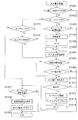
〔遊技制御部による大入賞口処理〕
図14は、図5−3のS504に示した電動役物処理のうちの大入賞口処理の内容を示
すフローチャートである。
この大入賞口処理において、遊技制御部200の大入賞口動作制御部237は、まず、
RAM203のフラグ設定において当たり遊技フラグがONになっているか否かを調べる
(S1401)。当たり遊技フラグがOFFである場合、大入賞口125への入賞はない
ので、大入賞口処理を終了する(S1401でNo)。一方、当たり遊技フラグがONで
ある場合(S1401でYes)、次に大入賞口動作制御部237は、パチンコ遊技機1
00が停止中処理(図11)で開始された大当たり時の動作制御におけるオープニング動
作の最中か否かを判断する(S1402)。
[Large winning mouth processing by game control unit]
FIG. 14 is a flowchart showing the contents of the big prize opening process in the electric accessory process shown in S504 of FIG. 5-3.
In this special winning opening process, the special winning opening
It is checked whether or not the winning game flag is ON in the flag setting of the RAM 203 (S1401). If the winning game flag is OFF, there is no prize winning in the
It is determined whether 00 is in the middle of the opening operation in the operation control at the big hit time started in the stop process (FIG. 11) (S1402).
パチンコ遊技機100がオープニング中である場合(S1402でYes)、次に大入
賞口動作制御部237は、予め設定されたオープニング動作が行われるべき時間(オープ
ニング時間)を経過したか否かを判断する(S1403)。オープニング時間を経過して
いないならば、大入賞口125でのオープニング動作が継続されるので、大入賞口処理を
終了する(S1403でNo)。一方、オープニング時間を経過したならば(S1403
でYes)、次に大入賞口動作制御部237は、大入賞口125の作動設定を行い(S1
404)、入賞個数Cを初期化(C=0)し(S1405)、大入賞口125の作動のラ
ウンド数Rの値を現在の値から1加算して(S1406)、大入賞口125を作動開始(
開放)する(S1407)。
When the
Next, the special prize opening
404), the winning number C is initialized (C = 0) (S1405), and the value of the number R of rounds of operation of the
Open) (S1407).
S1404の作動設定では、大入賞口125の作動パターンと、その作動パターンで作
動させるラウンド数(作動ラウンド数)とが設定される。大入賞口125が作動する場合
としては、特別図柄抽選で、長当たりまたは短当たりの大当たりであった場合と、小当た
りであった場合がある。作動パターンおよびラウンド数は、これらの当たりの種類に応じ
て様々に設定される。なお、大当たり遊技においては、大入賞口125の作動を複数回(
複数ラウンド)連続して行うことが規定されている。一例としては、長当たりの場合、例
えば、15ラウンド(15R)作動させ、1ラウンドでは29.5秒の開放を1回行う。
短当たりの場合、例えば、15ラウンド(15R)作動させ、1ラウンドでは0.1秒の
開放を1回行う。小当たりの場合、例えば、1ラウンド(1R)作動させ、この1ラウン
ドで0.1秒の開放を15回行う。ここで、短当たりでの作動と小当たりでの作動を上記
の例で比較すると、共に0.1秒の開放が15回行われることとなる。すなわち、遊技者
から見える大入賞口125の動作は、短当たりの場合と小当たりの場合とで同じであり、
遊技盤110上の大入賞口125の動作のみから短当たりと小当たりとを区別することは
できない。
In the operation setting of S1404, the operation pattern of the special winning
Multiple rounds) are specified to be performed continuously. As an example, in the case of a long hit, for example, 15 rounds (15R) are operated, and 29.5 seconds are released once in one round.
In the case of a short hit, for example, 15 rounds (15R) are operated, and one round is performed once for 0.1 seconds. In the case of a small hit, for example, one round (1R) is operated, and 0.1 second is released 15 times in this round. Here, when the operation with short hits and the operation with small hits are compared in the above examples, both 0.1 seconds of opening is performed 15 times. In other words, the action of the
It is not possible to distinguish between short wins and small hits only from the operation of the big winning
また、別の例としては、長当たりでは、15ラウンド(15R)作動させ、1ラウンド
では29.5秒の開放を1回行い、短当たりでは、2ラウンド(2R)作動させ、1ラウ
ンドでは0.9秒の開放を2回行い、小当たりでは、1ラウンド(1R)作動させ、この
1ラウンドで0.9秒の開放を2回行う。この場合も、短当たりでの作動と小当たりでの
作動を比較すると、共に0.9秒の開放が2回行われることとなり、遊技者から見える大
入賞口125の動作は、短当たりの場合と小当たりの場合とで同様となる。
As another example, 15 rounds (15R) are activated per long, 29.5 seconds are released once per round, 2 rounds (2R) are activated per short, and 0 are rounded per round. .9 seconds are opened twice, and with a small hit, one round (1R) is operated, and 0.9 seconds is opened twice in this round. In this case as well, when the operation with short hits and the operation with small hits are compared, both 0.9 seconds are released twice, and the action of the
なお、小当たりの際には、大入賞口125の開放累積時間が1.8秒以内に設定されな
ければならないことが法令により定められている。一方で、大当たり(長当たりまたは短
当たり)の際には、大入賞口125を複数回連続開放させなければならない。そこで、上
記のように小当たりでの作動と短当たりでの作動を外見上区別し難くしようとする場合、
小当たりでは、1作動での開放累積時間が1.8秒以内を満たす範囲で、大入賞口125
が2回以上開放する作動形態が設定され、短当たりでは、小当たりの開放回数と同数のラ
ウンド数が設定される。
The law stipulates that the cumulative opening time of the special winning
For small wins, the winning prize opening 125 is within the range that the accumulated opening time in one operation is within 1.8 seconds.
Is set to open twice or more, and in the short win, the same number of rounds as the number of small hits is set.
次に、大入賞口動作制御部237は、S1404で設定された作動パターンにおける開
放時間を経過したか否かを判断する(S1408)。大入賞口125での開放状態が開放
時間を経過していない場合(S1408でNo)、次に大入賞口動作制御部237は、大
入賞口125への入賞個数Cが規定の個数(例えば9個)以上か否かを判断する(S14
09)。開放時間を経過しておらず、かつ入賞個数Cが規定個数未満である場合は、大入
賞口125の作動状態(開放状態)が継続されるので、大入賞口処理を終了する(S14
09でNo)。一方、開放時間を経過したか(S1408でYes)、または入賞個数C
が規定個数に達した場合(S1409でYes)、大入賞口動作制御部237は、大入賞
口125を作動終了(閉口)する(S1410)。
Next, the special prize opening
09). If the opening time has not elapsed and the number C of winning prizes is less than the specified number, the operating state (open state) of the big winning
09, No). On the other hand, whether the opening time has elapsed (Yes in S1408), or the number of winning prizes C
When the predetermined number is reached (Yes in S1409), the special prize opening
次に、大入賞口動作制御部237は、大入賞口125の作動のラウンド数RがS140
4で設定された最大値に達したか否かを判断する(S1411)。そして、最大値に達し
ていないならば、残りの作動が行われるため、大入賞口処理を終了する(S1411でN
o)。
Next, the prize winning opening
It is determined whether or not the maximum value set in 4 has been reached (S1411). If the maximum value has not been reached, the remaining operations are performed, so that the big prize opening process is terminated (N in S1411).
o).
大入賞口125の作動のラウンド数Rが最大値に達したならば(S1411でYes)
、次に大入賞口動作制御部237は、エンディング動作を開始する(S1412)。ここ
で、エンディング動作の内容は、長当たり遊技、短当たり遊技の各遊技において設定され
たエンディング動作のうち、当たり遊技フラグの状態に対応するものとなる。
この後、大入賞口動作制御部237は、演出制御部300において当たり遊技フラグに
応じたエンディング動作における演出を行うためのエンディングコマンドをRAM203
に設定された制御コマンド用の所定の格納領域にセットする(S1413)。このエンデ
ィングコマンドは、図5−3のS506に示した出力処理で演出制御部300へ送信され
る。
If the number R of rounds of operation of the
Next, the special winning opening
Thereafter, the special winning opening
Is set in a predetermined storage area for the control command set in (S1413). This ending command is transmitted to the
次に、大入賞口動作制御部237は、大入賞口125の作動のラウンド数Rを0にリセ
ットした後(S1414)、エンディング動作の開始からの経過時間が予め設定されたエ
ンディング動作が行われるべき時間(エンディング時間)を経過したか否かを判断する(
S1417)。エンディング時間を経過していないならば、エンディング動作が継続され
るので、大入賞口処理を終了する(S1417でNo)。一方、エンディング時間を経過
したならば(S1417でYes)、次に大入賞口動作制御部237は、遊技制御部20
0による遊技状態設定処理を経た後(S1418)、当たり遊技フラグをOFFにして、
大入賞口処理を終了する(S1419)。遊技状態設定処理の内容については後述する。
Next, the special winning opening
S1417). If the ending time has not elapsed, the ending operation is continued, and thus the big prize opening process is terminated (No in S1417). On the other hand, if the ending time has elapsed (Yes in S1417), the special winning opening
After the game state setting process by 0 (S1418), the winning game flag is turned OFF,
The big prize opening process is terminated (S1419). The contents of the game state setting process will be described later.
S1402で、パチンコ遊技機100がオープニング中ではないと判断した場合(S1
402でNo)、次に大入賞口動作制御部237は、エンディング中か否かを判断する(
S1415)。そして、エンディング中であるならば(S1415でYes)、上記S1
417以降の動作を実行する。
When it is determined in S1402 that the
Next, the special winning opening
S1415). If it is ending (Yes in S1415), the above S1
The operation after 417 is executed.
一方、パチンコ遊技機100がエンディング中でもないならば(S1415でNo)、
次に大入賞口動作制御部237は、大入賞口125が作動(開放)中か否かを判断する(
S1416)。そして、作動中でないならば(S1416でNo)、上記S1405以降
の動作を実行し、作動中であるならば(S1416でYes)、上記S1408以降の動
作を実行する。
なお、前述した小当たり遊技で行われる演出は、短当たり遊技で行われる演出と同様で
あり、演出から短当たりと小当たりとを区別することはできない。
On the other hand, if the
Next, the special prize opening
S1416). If it is not in operation (No in S1416), the operation after S1405 is executed. If it is in operation (Yes in S1416), the operation after S1408 is executed.
The effect performed in the small hit game described above is the same as the effect performed in the short hit game, and it is not possible to distinguish short hit and small hit from the effect.
〔遊技状態設定処理〕
エンディング時間が経過した場合(S1417でYes)に実行される、遊技制御部2
00による遊技状態設定処理(S1418)の内容を図15に示す。
遊技状態設定処理が行われる場合、前提として、図14のS1401で当たり遊技フラ
グがONとなっている。そこで、図15に示すように、遊技制御部200は、まず、その
当たりの種類を判断する(S1501、S1502、S1503、S1506)。これら
の判断は、例えば大当たり判定処理(図9)でRAM203に設定情報としてセットされ
た図柄の種類に基づいて判断することができる。なお、これらの判断は大当たり判定処理
(図9)のS902、S903、S905と概ね同様であるので、S902、S903、
S905の判断結果を用いても良い。
[Game state setting process]
The
FIG. 15 shows the contents of the game state setting process (S1418) based on 00.
When the game state setting process is performed, as a premise, the winning game flag is set to ON in S1401 of FIG. Therefore, as shown in FIG. 15, the
The determination result of S905 may be used.
小当たりである場合(S1501でYes)、遊技状態(パチンコ遊技機100の内部
状態)は変更しないので、遊技状態設定処理を終了する。
当たりの種類が低確率時短遊技状態の大当たりである場合(S1501でNo、S15
02、S1503でYes)、遊技制御部200は、時短フラグをONにする(S150
4)。これにより、RAM203の遊技状態の設定が低確率時短遊技状態となる。また、
遊技制御部200は、抽選回数Jの初期値を設定し(S1505)、遊技状態設定処理を
終了する。抽選回数Jの初期値は、図示の例では100回である。したがって、低確率時
短遊技状態における抽選が100回行われたならば、低確率時短遊技状態が終了し、低確
率時短無遊技状態となる。
If it is a small hit (Yes in S1501), the gaming state (internal state of the pachinko gaming machine 100) is not changed, so the gaming state setting process is terminated.
When the hit type is a jackpot of the low-probability short game state (No in S1501, S15
02, Yes in S1503), the
4). Thereby, the setting of the gaming state in the
The
一方、当たりの種類が低確率時短無遊技状態の大当たりである場合(S1501でNo
、1502でYes、S1503でNo)、遊技制御部200は、時短フラグ、確変フラ
グともONにせずに処理を終了する。したがって、この大当たりの後の遊技に対するRA
M203の遊技状態の設定は、低確率時短無遊技状態となる。
On the other hand, when the hit type is a jackpot in the low probability short-time non-game state (No in S1501)
, 1502 is Yes, and S1503 is No), the
The game state setting of M203 is a low probability and short no-game state.
当たりの種類が高確率時短遊技状態の大当たりである場合(S1501、S1502で
No、S1506でYes)、遊技制御部200は、時短フラグをONにし(S1507
)、抽選回数Jの初期値を設定する(S1508)。この場合の抽選回数Jの初期値は、
図示の例では10000回である。また、遊技制御部200は、確変フラグをONにし(
S1509)、抽選回数Xの初期値を設定する(S1510)。抽選回数Xの初期値は、
図示の例では10000回である。これにより、RAM203の遊技状態の設定が高確率
時短遊技状態となる。そして、この高確率時短遊技状態における抽選が10000回行わ
れたならば、高確率時短遊技状態が終了し、低確率時短無遊技状態となる。
When the winning type is a big hit in the high probability short-time gaming state (No in S1501, S1502, Yes in S1506), the
), The initial value of the number of times of lottery J is set (S1508). In this case, the initial value of the lottery number J is
In the example shown, it is 10,000 times. In addition, the
(S1509), an initial value of the number of times of lottery X is set (S1510). The initial value of the lottery number X is
In the example shown, it is 10,000 times. As a result, the setting of the gaming state in the
一方、当たりの種類が高確率時短無遊技状態の大当たりである場合(S1501、S1
502、S1506でNo)、遊技制御部200は、確変フラグのみをONにし(S15
09)、抽選回数Xの初期値(10000回)を設定する(S1510)。これにより、
RAM203の遊技状態の設定が高確率時短無遊技状態となる。そして、この高確率時短
無遊技状態における抽選が10000回行われたならば、高確率時短無遊技状態が終了し
、低確率時短無遊技状態となる。
On the other hand, when the hit type is a jackpot of the high probability short-time non-game state (S1501, S1
502, No in S1506), the
09), an initial value (10000 times) of the lottery number X is set (S1510). This
The setting of the game state in the
〔遊技制御部による電動チューリップ処理〕
図16は、図5−3のS504に示した電動役物処理のうちの電動チューリップ処理の
内容を示すフローチャートである。
電動チューリップ処理において、遊技制御部200の電動チューリップ動作制御部23
8は、まず、RAM203のフラグ設定において補助遊技フラグがONになっているか否
かを調べる(S1601)。補助遊技フラグがOFFである場合、電動チューリップ12
3は開放しないため、電動チューリップ処理を終了する(S1601でNo)。一方、補
助遊技フラグがONである場合(S1601でYes)、次に電動チューリップ動作制御
部238は、電動チューリップ123が作動中か否かを判断する(S1602)。
[Electric tulip processing by game control unit]
FIG. 16 is a flowchart showing the contents of the electric tulip process in the electric accessory process shown in S504 of FIG. 5-3.
In the electric tulip process, the electric tulip operation control unit 23 of the
8. First, it is checked whether or not the auxiliary game flag is ON in the flag setting of the RAM 203 (S1601). When the auxiliary game flag is OFF, the
Since 3 does not open, the electric tulip process is terminated (No in S1601). On the other hand, if the auxiliary game flag is ON (Yes in S1601), the electric tulip
電動チューリップ123が作動中でない場合(S1602でNo)、電動チューリップ
動作制御部238は、電動チューリップ123の作動パターンの設定を行い(S1603
)、設定した作動パターンで電動チューリップ123を作動させる(S1604)。ここ
で、作動パターンは、図11におけるS1104、S1114、図15におけるS150
4、S1507等の処理で設定される時短フラグに基づいて設定される。例えば、S16
03による設定の際に時短フラグがOFFである場合は、0.15秒の開放時間で1回開
放する作動パターンが設定され、時短フラグがONである場合は、1.80秒の開放時間
で3回開放する作動パターンが設定される。このように、通常、時短フラグがONである
とき(時短状態のとき)は、電動チューリップ123が長時間、複数回開放され、第2始
動口122に入賞し易くなる入賞サポート(電チューサポート)が行われる。なお、時短
フラグがONの場合またはOFFの場合における電動チューリップ123の作動パターン
(補助遊技の種類)を複数用意し、普通図柄処理(図13参照)で判定される当たりの種
類に応じて、作動パターンを設定するように構成しても良い。
If the electric tulip 123 is not in operation (No in S1602), the electric tulip
) The electric tulip 123 is operated with the set operation pattern (S1604). Here, the operation patterns are S1104 and S1114 in FIG. 11, and S150 in FIG.
4. Set based on the time reduction flag set in the processing such as S1507. For example, S16
When the time reduction flag is OFF when setting by 03, an operation pattern is set to open once with an opening time of 0.15 seconds, and when the time reduction flag is ON, an opening time of 1.80 seconds is set. An operating pattern that opens three times is set. Thus, normally, when the time reduction flag is ON (when it is in the time reduction state), the electric tulip 123 is opened a plurality of times for a long time, and the winning support that makes it easy to win the second start port 122 (electricity chewing support). Is done. A plurality of operation patterns (types of auxiliary games) of the electric tulip 123 when the time flag is ON or OFF are prepared, and the operation is performed according to the type determined in the normal symbol processing (see FIG. 13). You may comprise so that a pattern may be set.
S1602で電動チューリップ123が作動中と判断された場合(S1602でYes
)、またはS1604で電動チューリップ123を作動させた後、電動チューリップ動作
制御部238は、設定されている作動パターンにおける開放時間が経過したか否かを判断
する(S1605)。開放時間を経過していなければ、電動チューリップ123の作動状
態(開放状態)が継続されるので、電動チューリップ処理を終了する(S1605でNo
)。一方、開放時間を経過したならば(S1605でYes)、電動チューリップ動作制
御部238は、補助遊技フラグをOFFとして、電動チューリップ処理を終了する(S1
606)。
When it is determined in S1602 that the electric tulip 123 is operating (Yes in S1602)
) Or after operating the electric tulip 123 in S1604, the electric tulip
). On the other hand, if the opening time has elapsed (Yes in S1605), the electric tulip
606).
〔乱数による判定の手法〕
ここで、大当たり判定処理(図9)、変動パターン選択処理(図10)、普通図柄処理
(図13)等で行われる、乱数による判定の手法について詳細に説明する。
図17は、本実施の形態において特別図柄抽選および普通図柄抽選で用いられる乱数(
判定テーブル)の構成例を示す図である。
図17(a)には特別図柄抽選で用いられる大当たり乱数の構成例、図17(b)には
特別図柄抽選で用いられる大当たり図柄乱数の構成例、図17(c)には特別図柄抽選で
用いられるリーチ乱数の構成例、図17(d)には普通図柄抽選で用いられる当たり乱数
の構成例が、それぞれ示されている。
[Random number judgment method]
Here, a determination method using random numbers performed in the jackpot determination process (FIG. 9), the variation pattern selection process (FIG. 10), the normal symbol process (FIG. 13), and the like will be described in detail.
FIG. 17 shows a random number used in the special symbol lottery and the normal symbol lottery in this embodiment (
It is a figure which shows the structural example of a determination table.
FIG. 17A shows a configuration example of a jackpot random number used in the special symbol lottery, FIG. 17B shows a configuration example of the jackpot random number used in the special symbol lottery, and FIG. 17C shows a special symbol lottery. A configuration example of reach random numbers used, and FIG. 17 (d) each show a configuration example of hit random numbers used in normal symbol lottery.
図17(a)を参照すると、大当たり乱数の判定値として、大当たり遊技後のパチンコ
遊技機100の遊技状態が低確率状態となる大当たり(以下、低確率状態の大当たり)と
大当たり遊技後の遊技状態が高確率状態となる大当たり(以下、高確率状態の大当たり)
の2種類と、小当たりとが設定されている。乱数(大当たり乱数)の値の範囲は、いずれ
も0〜299の300個である。低確率状態の特別図柄抽選(大当たり抽選)の場合、当
選値は1つだけが設定され、当選確率は1/300である。また高確率状態の特別図柄抽
選の場合、当選値は10個設定され、当選確率は10/300(=1/30)である。す
なわち図示の例では、高確率状態で始動口121、122に入賞し特別図柄抽選が行われ
ると、低確率状態で特別図柄抽選が行われる場合に比べて、当選確率が10倍となる。ま
た、小当たりの当選値は、低確率状態か高確率状態かに関わらず3個設定され、当選確率
は3/300(=1/100)である。
Referring to FIG. 17 (a), as the determination value of the jackpot random number, the jackpot in which the gaming state of the
2 types and small hits are set. The range of values of random numbers (big hit random numbers) is 300 from 0 to 299 in all cases. In the case of a special symbol lottery in a low probability state (a jackpot lottery), only one winning value is set, and the winning probability is 1/300. In the case of a special symbol lottery in a high probability state, 10 winning values are set, and the winning probability is 10/300 (= 1/30). That is, in the example shown in the figure, if the winning
図17(b)を参照すると、大当たり図柄には、低確率図柄A、低確率図柄B、高確率
図柄A、高確率図柄B、潜確図柄の5種類が用意されている。ここで、低確率図柄Aおよ
び低確率図柄Bは、低確率状態の大当たりであることを表す図柄であり、このうち低確率
図柄Aは長当たり(低確率時短遊技状態の大当たり)、低確率図柄Bは短当たり(低確率
時短無遊技状態の大当たり)をそれぞれ表す。高確率図柄Aおよび高確率図柄Bは、高確
率状態の大当たりであることを表す図柄であり、このうち高確率図柄Aは長当たり(高確
率時短遊技状態の大当たり)、高確率図柄Bは短当たり(高確率時短無遊技状態の大当た
り)をそれぞれ表す。潜確図柄は、高確率時短無遊技状態の大当たりであることを表す図
柄である。したがって、高確率図柄Bと潜確図柄とは大当たり遊技後の遊技状態が同じで
あるが、潜確図柄は、高確率状態であることを遊技者に明確に報知しない潜伏演出を行う
条件とするために高確率図柄Bとは分けて設けられている。乱数(大当たり図柄乱数)の
値の範囲は0〜249の250個である。また、大当たり図柄乱数では、特別図柄抽選が
行われる契機となる第1始動口121と第2始動口122の各々について当選値が設定さ
れる。
Referring to FIG. 17 (b), five types of jackpot symbols are prepared: low probability symbol A, low probability symbol B, high probability symbol A, high probability symbol B, and latent symbol symbol. Here, the low-probability symbol A and the low-probability symbol B are symbols representing a jackpot in a low-probability state, and among these, the low-probability symbol A is a long-spot (a jackpot in a low-probability gaming state) and a low-probability symbol. B represents a short win (a big hit in a low no-game state with a low probability). The high-probability symbol A and the high-probability symbol B are symbols that represent a jackpot of a high-probability state. Among these symbols, the high-probability symbol A is a long-spot (a jackpot for a high-probability short-time gaming state), and the high-probability symbol B is a short-spot Each win (a big hit with a high probability short and no game state) is represented. The latent symbol is a symbol representing that it is a big hit in a high probability short-time no-game state. Therefore, the high probability symbol B and the latent probability symbol have the same gaming state after the jackpot game, but the latent probability symbol is a condition for performing a latent effect that does not clearly notify the player that the probability state is high. Therefore, it is provided separately from the high probability symbol B. The range of values of random numbers (big hit symbol random numbers) is 250 from 0 to 249. In addition, in the jackpot symbol random number, winning values are set for each of the
低確率図柄Aでは、第1始動口121および第2始動口122ともに、当選値として3
5個の値が割り当てられている。したがって、大当たりに当選した場合に低確率図柄Aで
の当選となる確率は、35/250(=7/50)である。
低確率図柄Bでは、第1始動口121および第2始動口122ともに、当選値として1
5個の値が割り当てられている。したがって、大当たりに当選した場合に低確率図柄Bで
の当選となる確率は、15/250(=3/50)である。
In the low probability pattern A, the
Five values are assigned. Therefore, the probability of winning with the low probability symbol A when winning a jackpot is 35/250 (= 7/50).
In the low probability pattern B, both the
Five values are assigned. Therefore, when winning the jackpot, the probability of winning with the low probability symbol B is 15/250 (= 3/50).
高確率図柄Aでは、第1始動口121に入賞した場合の当選値として25個の値が割り
当てられている。したがって、第1始動口121に入賞したことによって開始された特別
図柄抽選において大当たりに当選した場合に高確率図柄Aでの当選となる確率は、25/
250(=1/10)である。
一方、第2始動口122に入賞した場合の当選値として175個の値が割り当てられて
いる。したがって、第2始動口122に入賞したことによって開始された特別図柄抽選に
おいて大当たりに当選した場合に高確率図柄Aでの当選となる確率は、175/250(
=7/10)である。
In the high probability symbol A, 25 values are assigned as winning values when winning in the
250 (= 1/10).
On the other hand, 175 values are assigned as winning values when winning at the second start port 122. Therefore, when winning a jackpot in the special symbol lottery started by winning the second starting port 122, the probability of winning with the high probability symbol A is 175/250 (
= 7/10).
高確率図柄Bでは、第1始動口121に入賞した場合の当選値として75個の値が割り
当てられている。したがって、第1始動口121に入賞したことによって開始された特別
図柄抽選において大当たりに当選した場合に高確率図柄Bでの当選となる確率は、75/
250(=3/10)である。
一方、第2始動口122に入賞した場合の当選値として25個の値が割り当てられてい
る。したがって、第2始動口122に入賞したことによって開始された特別図柄抽選にお
いて大当たりに当選した場合に高確率図柄Bでの当選となる確率は、25/250(=1
/10)である。
In the high-probability symbol B, 75 values are assigned as winning values when winning in the
250 (= 3/10).
On the other hand, 25 values are assigned as winning values when winning at the second start port 122. Therefore, the probability of winning with the high-probability symbol B when winning a jackpot in the special symbol lottery started by winning the second starting port 122 is 25/250 (= 1
/ 10).
潜確図柄では、第1始動口121に入賞した場合の当選値として100個の値が割り当
てられている。したがって、第1始動口121に入賞したことによって開始された特別図
柄抽選において大当たりに当選した場合に潜確図柄での当選となる確率は、100/25
0(=2/5)である。
一方、第2始動口122には潜確図柄での当選値が割り当てられておらず、第2始動口
122に入賞した場合に潜確図柄での当選となることはない。
In the latent symbol, 100 values are assigned as winning values when winning at the
0 (= 2/5).
On the other hand, the winning value in the latent symbol is not assigned to the second starting port 122, and when winning in the second starting port 122, it is not won in the latent symbol.
以上のように、図17(b)に示す例では、第1始動口121に入賞した場合の大当た
りは、高確率時短無遊技状態の大当たり(高確率図柄B、潜確図柄)となる確率が高く、
第2始動口122に入賞した場合の大当たりは、高確率時短遊技状態の大当たり(高確率
図柄A)となる確率が高い。このように、第1始動口121に入賞した場合と第2始動口
122に入賞した場合における大当たりの種類の当選確率を相違させることにより、様々
な遊技性を持たせることができる。また、遊技盤110における第1始動口121と第2
始動口122の配置を工夫し、特定の状態(モード)では第1始動口121と第2始動口
122のいずれか一方を狙い易くなるように構成することによって、遊技者にさらに積極
的な遊技への参加を促すことも可能である。
As described above, in the example shown in FIG. 17B, the jackpot when winning the
The jackpot when winning at the second start port 122 has a high probability of being a jackpot (high probability symbol A) in the high probability short-time gaming state. In this way, by making the winning probabilities of the jackpot types different when winning at the
A game that is more aggressive to the player by devising the arrangement of the start port 122 so that it is easy to aim at either the
次に、リーチ乱数の判定について説明する。
図17(c)を参照すると、乱数の値の範囲は0〜249の250個であり、リーチ演
出を行う抽選結果(リーチ有)に22個の乱数値が割り当てられ、リーチ演出を行わない
抽選結果(リーチ無)に228個の乱数値が割り当てられている。すなわち図示の例では
、特別図柄抽選で大当たりしなかった場合に、22/250(=11/125)の確率で
リーチ演出が行われる。ここで、リーチ演出は、特別図柄変動時に画像表示部114にお
いて行われる演出である。以下、リーチ演出を行わない特別図柄変動時の演出をリーチ無
し演出と呼び、これに対応してリーチ演出をリーチ有り演出とも呼ぶ。
Next, the determination of reach random numbers will be described.
Referring to FIG. 17 (c), the range of random number values is 250 from 0 to 249, and 22 random numbers are assigned to the lottery result (with reach) for performing the reach effect, and the reach effect is not performed. 228 random numbers are assigned to the result (no reach). In other words, in the illustrated example, when a special symbol lottery is not won, a reach effect is performed with a probability of 22/250 (= 11/125). Here, the reach effect is an effect performed in the
多くの場合、特別図柄変動時には、第1特別図柄表示器221および第2特別図柄表示
器222(以下、これらを区別しない場合は特別図柄表示器221、222と記載)の表
示制御に連動させて、画像表示部114において装飾図柄を用いた演出が行われる。装飾
図柄は、例えば、1〜9の数字が縦方向に連続して記された数列からなる図柄が三列表示
されて構成される。そして、特別図柄表示器221、222における特別図柄の変動表示
が開始されるのと同時に、画像表示部114に表示された装飾図柄がスクロールを開始す
る。また、特別図柄が停止表示されるのと同時に、装飾図柄も停止する。一般に、特別図
柄抽選の判定結果が大当たりである場合、装飾図柄の停止表示では、横または斜めにわた
る一直線上に同一の数字が三つ揃って並ぶ。この特別図柄の変動表示に伴って行われる装
飾図柄を用いた演出を変動演出と呼ぶ。
In many cases, when the special symbol changes, the first
リーチ有り演出においては、変動演出として、装飾図柄に関して次のような固有の動作
が行われる。まず、装飾図柄のスクロールが停止して各図柄を停止表示する際に、まず、
いずれか2つの図柄(数列)が先に停止する。このとき、横または斜めにわたる一直線上
に同一の数字が停止表示される。次に、最後の一列がスクロール速度を徐々に遅くして、
一直線上に同一の数字が三つ揃うのではないかという期待感を遊技者に与える。このよう
なリーチ有り演出では、最後の1列のスクロールが停止する前に、さまざまなキャラクタ
が登場したり、ストーリーが展開したりするいわゆるスーパーリーチ演出が行われる場合
がある。また、リーチ有り演出と共に行われる上記の変動演出をリーチ時変動演出とも呼
ぶ。
一方、リーチ無し演出においては、リーチ有り演出のような遊技者に期待感を与える演
出がなされることなく、横または斜めにわたる一直線上に同一の数字が揃わない状態で図
柄が停止表示する。
In the production with reach, the following unique operation is performed with respect to the decorative design as a variation production. First, when scrolling of decorative symbols stops and each symbol is stopped and displayed,
Any two symbols (sequence) stop first. At this time, the same number is stopped and displayed on a straight line extending horizontally or diagonally. Next, the last row gradually slows down the scrolling speed,
Gives players a sense of expectation that three identical numbers will be on a straight line. In such an effect with reach, there may be a so-called super reach effect in which various characters appear or a story develops before the last one column of scrolling stops. In addition, the above-described variation effect performed together with the reach effect is also referred to as a reach variation effect.
On the other hand, in the non-reach effect, the design is stopped and displayed in a state where the same numbers are not aligned on a straight line extending horizontally or diagonally without producing an effect that gives the player a sense of expectation like the effect with reach.
このように、リーチ乱数は、大当たり乱数の判定の結果がはずれであった場合に、画像
表示部114においてリーチ有り演出を行うか、リーチ無し演出を行うかを決定するため
のもので、所定の確率でリーチ有り演出が出現するようにして、遊技者に対して適度に期
待感を与えるようにしている。
付言すると、大当たりに当選した場合には、リーチ有り演出が必ず行われ、最終的に横
または斜めにわたる一直線上に、同一の数字が揃った状態で装飾図柄が停止表示する。こ
れに対して、小当たりに当選した場合やはずれの場合のリーチ有り演出は、上記一直線上
に、同一の数字が揃わない状態で装飾図柄が停止表示する。
As described above, the reach random number is used to determine whether to perform the effect with reach or the effect without reach in the
In addition, when a big win is won, a reachable effect is always performed, and finally the decorative symbols are stopped and displayed in a state where the same numbers are aligned on a straight line extending horizontally or diagonally. On the other hand, in the case of winning with a small win or a loss effect, the decorative symbols are stopped and displayed in a state where the same numbers are not aligned on the straight line.
次に、普通図柄抽選に用いられる当たり乱数の判定について説明する。
図17(d)を参照すると、乱数の値の範囲は0〜9の10個であり、時短フラグOF
Fのときの当選値として1個の値が割り当てられ、時短フラグONのときの当選値として
9個の値が割り当てられている。したがって、時短無状態のときにゲート124を遊技球
が通過して普通図柄抽選が行われると、1/10の確率で当選する。これに対し、時短状
態のときにゲート124を遊技球が通過して普通図柄抽選が行われると、9/10の確率
で当選する。
また、特に図示していないが、普通図柄抽選で当たりと判定された場合に行われる補助
遊技の内容(電動チューリップ123の開放パターン)が異なる複数の当たりを設定する
ことができる。この場合、例えば、特別図柄抽選における大当たりの種類を特定する大当
たり図柄乱数(図17(b)参照)と同様に、普通図柄抽選における当たりの種類を特定
するための当たり図柄乱数が設定される。そして、遊技制御部200は、乱数取得部23
1により、ゲートスイッチ処理(図7参照)で当たり乱数の乱数値と共に、当たり図柄乱
数の乱数値を取得し、普通図柄判定部232により、取得された乱数値に基づいて当たり
の種類を特定する。
なお、図17の各乱数の構成例に示した乱数の範囲、当選値の割合、当選値の各値は例
示に過ぎず、図示の値に限定されるものではない。
Next, the determination of the winning random number used for the normal symbol lottery will be described.
Referring to FIG. 17 (d), the range of the random number value is 10 from 0 to 9, and the time reduction flag OF.
One value is assigned as the winning value at F, and nine values are assigned as the winning values at the time flag ON. Therefore, when the game ball passes through the
In addition, although not particularly illustrated, it is possible to set a plurality of hits with different contents of the auxiliary game (open pattern of the electric tulips 123) performed when it is determined that the normal symbol lottery is won. In this case, for example, the winning symbol random number for specifying the winning type in the normal symbol lottery is set in the same manner as the jackpot symbol random number for specifying the winning symbol type in the special symbol lottery (see FIG. 17B). And
1, the random number value of the winning symbol random number is obtained together with the random number value of the winning random number in the gate switch process (see FIG. 7), and the normal
Note that the random number range, winning value ratio, and winning value shown in the configuration example of each random number in FIG. 17 are merely examples, and are not limited to the illustrated values.
〔変動パターンの設定例〕
次に、図10に示した変動パターン選択処理において用いられる変動パターンの設定例
について説明する。
図18は、図10に示した変動パターン選択処理において用いられる変動パターンの設
定例を示す図である。
図18に示す例では、特別図柄抽選の判定結果が大当たりであった場合(図10のS1
001でYesの場合)の変動パターンとして、3種類の変動パターンA〜Cが設定され
ている。また、特別図柄抽選の判定結果がはずれ(図10のS1001でNoの場合)で
あった場合の変動パターンとして、6種類の変動パターンD〜Iが設定されている。変動
時間は、変動パターンAが90秒、変動パターンBが60秒、変動パターンCが30秒、
変動パターンDが60秒、変動パターンEが30秒、変動パターンFが15秒、変動パタ
ーンGが13秒、変動パターンHが7秒、変動パターンIが3秒にそれぞれ設定されてい
る。すなわち、特別図柄の変動パターンは、特別図柄抽選における判定結果および特別図
柄の変動時間を定める。
[Setting example of fluctuation pattern]
Next, an example of setting a variation pattern used in the variation pattern selection process shown in FIG. 10 will be described.
FIG. 18 is a diagram illustrating a setting example of a variation pattern used in the variation pattern selection process illustrated in FIG.
In the example shown in FIG. 18, when the determination result of the special symbol lottery is a big hit (S1 in FIG. 10).
Three types of variation patterns A to C are set as variation patterns (in the case of Yes in 001). In addition, six types of variation patterns D to I are set as variation patterns when the determination result of the special symbol lottery is out of place (in the case of No in S1001 in FIG. 10). The fluctuation time is 90 seconds for fluctuation pattern A, 60 seconds for fluctuation pattern B, 30 seconds for fluctuation pattern C,
The fluctuation pattern D is set to 60 seconds, the fluctuation pattern E is set to 30 seconds, the fluctuation pattern F is set to 15 seconds, the fluctuation pattern G is set to 13 seconds, the fluctuation pattern H is set to 7 seconds, and the fluctuation pattern I is set to 3 seconds. That is, the special symbol variation pattern determines the determination result in the special symbol lottery and the special symbol variation time.
また、変動パターンD〜Fは、リーチ演出が行われる場合(図10のS1004でYe
sの場合)に選択される変動パターンであり、変動パターンG〜Iは、リーチ演出が行わ
れない場合(図10のS1004でNoの場合)に選択される変動パターンとして設定さ
れている。変動パターンD〜Fのようにリーチ演出を伴う変動パターンによる特別図柄変
動をリーチ変動とも呼ぶ。なお、特別図柄抽選の判定結果が大当たりのときには必ずリー
チ演出を行うように構成しているため、変動パターンA〜Cが選択される場合においてリ
ーチ演出の有無は参照されない。
Further, the variation patterns D to F are displayed when a reach effect is performed (S1004 in FIG. 10 shows Yes).
The variation patterns G to I are set as variation patterns to be selected when the reach effect is not performed (No in S1004 in FIG. 10). Special symbol variations due to variation patterns with reach effects such as variation patterns D to F are also referred to as reach variations. Since the reach effect is always performed when the determination result of the special symbol lottery is a big hit, the presence or absence of the reach effect is not referred to when the variation patterns A to C are selected.
さらに、変動パターンG〜Iのうち、変動パターンGは保留数が0個であるとき、変動
パターンHは保留数が1個または2個であるとき、変動パターンIは保留数が3個または
4個であるときにそれぞれ選択される変動パターンとして設定されている。すなわち、特
別図柄抽選における判定の保留数が多いほど、特別図柄変動の平均時間が短くなるように
設定されている。
Further, among the variation patterns G to I, when the variation pattern G has a holding number of 0, when the variation pattern H has one or two holding numbers, the variation pattern I has a holding number of three or four. It is set as a variation pattern that is selected for each of the individual patterns. That is, the average time of the special symbol variation is set to be shorter as the number of pending determinations in the special symbol lottery is larger.
遊技制御部200は、遊技球が始動口121、122に入賞した際に取得した変動パタ
ーン乱数値(図6のS604、S610参照)と、図18の設定例に示す判定結果、リー
チ演出の有無、保留数等の条件とに基づいて特別図柄の変動パターンを決定する。そして
、決定された特別図柄の変動パターンの情報は、変動開始コマンドに含まれて、遊技制御
部200から演出制御部300へ送られる。演出制御部300では、後述するように、特
別図柄変動時の演出として、変動開始コマンドに含まれる変動パターンの情報に基づいて
特定される変動時間に対応する(その変動時間で実行可能な)演出が選択されて実行され
る。
The
なお、図示はしていないが、特別図柄抽選の判定結果が大当たりであった場合に選択さ
れる変動パターンA〜Cのうち、最も高い割合で変動パターンAが選択され、次に高い割
合で変動パターンBが選択され、最も低い割合で変動パターンCが選択されるように設定
することができる。
また、図18に示した例では、遊技球が第1始動口121に入賞した場合と第2始動口
122に入賞した場合とを区別していないが、第1始動口121と第2始動口122のい
ずれに入賞したかに応じて変動パターンの設定を異ならせることもできる。
Although not shown, the variation pattern A is selected at the highest rate among the variation patterns A to C selected when the determination result of the special symbol lottery is a big hit, and the variation at the next highest rate. It can be set so that the pattern B is selected and the variation pattern C is selected at the lowest rate.
In the example shown in FIG. 18, there is no distinction between the case where the game ball wins the
〔制御コマンドの構成および伝送方式〕
ここで、遊技制御部200から演出制御部300へ出力されるコマンド(演出制御用コ
マンドおよび設定用コマンド)の構成および伝送方式について説明する。
図19−1は、コマンドの構成を示す図である。図19−1(a)はコマンドのデータ
構造を示し、図19−1(b)はコマンドのビット列としての構造を示す。
[Control command configuration and transmission method]
Here, the configuration and transmission method of commands (effect control commands and setting commands) output from the
FIG. 19A is a diagram illustrating a command configuration. 19A shows the data structure of the command, and FIG. 19A shows the structure of the command as a bit string.
図19−1(a)に示すように、遊技制御部200から演出制御部300へ出力される
コマンドは、1コマンドが2バイトで構成される。このコマンドは、第1データ部として
の1バイトの「コード部」と、第2データ部としての1バイトの「データ部」で構成され
ている。「コード部」には、コマンドの種類を示すコードが記述され、「データ部」には
、コマンドの値を示すデータが記述される。このコマンドは、1本のシリアル信号により
調歩同期を用いて、遊技制御部200から演出制御部300へ送信される。なお、より一
般的には、第1データ部である「コード」は、aビット(aは2以上の整数)のサイズで
、先頭の1ビットの値が1または0の何れか一方に特定され、第2データ部である「デー
タ」は、n×aビット(nは1以上の整数)のサイズで、先頭の1ビットの値が前記第1
データ部の先頭の1ビットの値とは異なる値に特定されている。
As shown in FIG. 19A, a command output from the
The value is specified to be different from the value of the first bit of the data portion.
調歩同期を用いるため、コマンドを構成する「コード部」および「データ部」の各々の
先頭には1ビットのスタートビット(図中、「S」と記載されたビット)が設けられ、最
後尾には1ビットのエンドビット(図中、「E」と記載されたビット)が設けられる。ま
た、コマンドを構成する「コード部」および「データ部」の各々には1ビットのパリティ
ビット(図中、「P」と記載されたビット)が設けられる。
Since start-stop synchronization is used, a 1-bit start bit (indicated by “S” in the figure) is provided at the head of each of the “code part” and “data part” that constitutes the command, and is added at the end. Is provided with one end bit (indicated by “E” in the figure). Each of the “code part” and “data part” constituting the command is provided with one parity bit (bit indicated as “P” in the figure).
図19−1(a)に示したように、コマンドを構成する「コード部」と「データ部」と
は、どちらも1バイト(8ビット)のデータサイズを有する。そして、伝送される際、「
コード部」および「データ部」には、それぞれ、スタートビット、エンドビットおよびパ
リティビットが設けられる。そのため、コマンドを受信する演出制御部300において、
受信したデータ列がコマンドの「コード部」であるのか「データ部」であるのかを、デー
タ列の外形から識別することは容易ではない。そこで、本実施の形態では、「コード部」
と「データ部」とを識別するためのフラグを設定する。具体的には、「コード部」を構成
する8ビット値の特定箇所の値と、「データ部」を構成する8ビット値のうち「コード部
」の特定箇所に対応する箇所の値とが異なるようにする。
As shown in FIG. 19A, both the “code part” and “data part” constituting the command have a data size of 1 byte (8 bits). And when it is transmitted,
The “code portion” and the “data portion” are each provided with a start bit, an end bit, and a parity bit. Therefore, in the
It is not easy to identify whether the received data string is the “code part” or “data part” of the command from the outline of the data string. Therefore, in this embodiment, the “code part”
And a flag for identifying the “data part”. Specifically, the value of the specific portion of the 8-bit value constituting the “code portion” is different from the value of the portion corresponding to the specific portion of the “code portion” among the 8-bit values constituting the “data portion”. Like that.
図19−1(b)に示す例では、「コード部」および「データ部」のそれぞれの先頭の
1ビットをフラグとして用いている。すなわち、「コード部」を構成する8ビット値にお
いては、先頭の1ビットの値を「1」とし、「データ部」を構成する8ビット値において
は、先頭の1ビットの値を「0」とする。これにより、演出制御部300は、受信したデ
ータ列のスタートビットに続く先頭の1ビットの値を調べることにより、そのデータ列が
「コード部」か「データ部」かを識別することができる。なお、フラグの具体的な値は例
示に過ぎず、「コード部」と「データ部」とを識別可能であれば、上記に示す値とは異な
る値を用いても良い。また、本実施の形態では、「コード部」および「データ部」を各々
8ビットのデータ列としているが、他のデータサイズ(aビット(aは2以上の整数))
であっても、同様の手法により「コード部」と「データ部」とを識別することが可能であ
る。
In the example shown in FIG. 19B, the first 1 bit of each “code part” and “data part” is used as a flag. That is, in the 8-bit value constituting the “code part”, the first 1-bit value is “1”, and in the 8-bit value constituting the “data part”, the first 1-bit value is “0”. And Thereby, the
Even so, the “code part” and the “data part” can be identified by the same method.
ここで、「コード部」は先頭の1ビットの値が「1」に特定されているので、「コード
部」が取り得る値の範囲は、10000000B(=80H)から11111111B(
=FFH)までの128個である。なお、各値に付された文字「B」は2進数表記である
ことを示し、文字「H」は16進数表記であることを示す。また、「データ部」は先頭の
1ビットの値が「0」に特定されているので、「データ部」が取り得る値の範囲は、00
000000B(=00H)から01111111B(=7FH)までの128個である
。すなわち、図19−1(a)、(b)に示す構成によれば、各々128種類の値を取り
得る、128種類のコマンドを設定することができる。そして、各コードの値と、遊技制
御部200のRAM203(図3参照)の各コマンド格納領域とを対応付けておくことに
より、生成されたコマンドは、そのコマンドが対応付けられたコマンド格納領域に格納さ
れることとなる。
Here, since the value of the first 1 bit of the “code part” is specified as “1”, the range of values that the “code part” can take is 10000000B (= 80H) to 11111111B (
= FFH). Note that the letter “B” attached to each value indicates binary notation, and the letter “H” indicates hexadecimal notation. In addition, since the value of the first 1 bit of the “data part” is specified as “0”, the range of values that the “data part” can take is 00
There are 128 from 000000B (= 00H) to 01111111B (= 7FH). That is, according to the configuration shown in FIGS. 19A and 19B, 128 types of commands that can take 128 types of values can be set. Then, by associating the value of each code with each command storage area of the RAM 203 (see FIG. 3) of the
ところで、パチンコ遊技機100では、遊技状態や特別図柄抽選の判定結果等に応じて
多くの種類の演出が実行される。そのため、演出制御用のコマンドも多くのコマンド数が
用意される。特に、コマンドの具体的な内容を示す値である「データ部」は、上記の12
8個では不足することもあり得る(例えば、特別図柄の変動パターンを特定するコマンド
等)。一方、コマンドの種類を示す「コード部」は、通常、上記の128個よりも小さい
数で足りる。そこで、「コード部」のビット列の一部を、「データ部」の値を記述するた
めに用いることが考えられる。
By the way, in the
Eight may be insufficient (for example, a command specifying a variation pattern of a special symbol). On the other hand, the “code part” indicating the type of command is usually smaller than the above 128. Therefore, it is conceivable to use a part of the bit string of “code part” to describe the value of “data part”.
例えば、「コード部」の最後尾の1ビットを「データ部」の値の記述に用いる場合を考
える。以下、「コード部」および「データ部」を構成する8ビットのビット列における各
ビットを、第1ビット〜第8ビットと呼ぶ。また、「コード部」を構成するビット列とは
別に、実際にコマンドの種類を示すコードの値を「コード値」と呼び、「データ部」を構
成するビット列とは別に、実際にコマンドの値を示すデータの値を「データ値」と呼ぶ。
すると、コード値は、「コード部」のビット列のうち、第1ビットから第7ビットまでを
用いて記述され、データ値は、「データ部」のビット列の全て(第1ビットから第8ビッ
トまで)と、「コード部」の第8ビットとを用いて記述される。
For example, consider the case where the last 1 bit of the “code part” is used to describe the value of the “data part”. Hereinafter, each bit in the 8-bit bit string constituting the “code portion” and the “data portion” is referred to as a first bit to an eighth bit. Separately from the bit string that constitutes the “code part”, the code value that actually indicates the type of command is called the “code value”, and separately from the bit string that constitutes the “data part”, the actual command value is The indicated data value is referred to as a “data value”.
Then, the code value is described using the first bit to the seventh bit in the bit string of the “code part”, and the data value is all of the bit string of the “data part” (from the first bit to the eighth bit). ) And the 8th bit of the “code part”.
このように構成すれば、コード値の取り得る範囲は、第1ビットの値が「1」に特定さ
れており、全体で7ビットのサイズであるので、1000000B(=40H)から11
11111B(=7FH)までの64個である。また、データ値の取り得る範囲は、第1
ビットの値が「0」に特定された「データ部」の8ビットで表現される128個と「コー
ド部」の第8ビットの値「0」、「1」とを合わせて、256個である。したがって、デ
ータ値として256種類の値を持つコマンドを設定することが可能となる。データ値の具
体的な範囲は、「データ部」の第1ビットの値が「0」に特定されているので、0000
00000B(=000H)〜001111111B(=07FH)、10000000
0B(=100H)〜101111111B(=17FH)となる。
With this configuration, the possible range of the code value is that the value of the first bit is specified as “1”, and the total size is 7 bits.
It is 64 up to 11111B (= 7FH). Also, the possible range of data values is the first
The 128 bits represented by the 8 bits of the “data part” whose bit value is specified as “0” and the 8th bit values “0” and “1” of the “code part” are combined into 256 pieces. is there. Therefore, it is possible to set a command having 256 kinds of values as data values. The specific range of the data value is 0000 because the value of the first bit of the “data portion” is specified as “0”.
00000B (= 000H) to 001111111B (= 07FH), 10000000
0B (= 100H) to 1011111111B (= 17FH).
別の見方によれば、上記の「コード部」の一部を用いてデータ値を記述する手法は、「
コード部」における第8ビットの値のみが異なる2種類のコードを有するコマンドを、同
一の種類のコマンドとして扱うことを意味する。例えば、変動パターンを特定するコマン
ドのコードの値を11011000B(=D8H)とした例において、上記の「コード部
」の一部を用いてデータ値を記述する手法を用いると、「コード部」の値1101100
0B(=D8H)の第8ビットの値が「1」となった値11011001B(=D9H)
を「コード部」の値とするコマンドも、変動パターンを特定するコマンドとして用いられ
ることとなる。
According to another view, the method of describing a data value using a part of the above "code part" is "
This means that commands having two types of codes that differ only in the value of the eighth bit in the “code portion” are handled as the same type of command. For example, in the example in which the code value of the command for specifying the variation pattern is 11011000B (= D8H), if a method of describing a data value using a part of the “code part” is used, Value 1101100
Value 11011001B (= D9H) in which the value of the eighth bit of 0B (= D8H) becomes “1”
A command having “code part” as a value is also used as a command for specifying a variation pattern.
なお、「コード部」の一部を用いてデータ値を記述する場合における上記の構成は例示
に過ぎず、具体的なビット数や値は上記の構成例には限定されない。例えば、「コード部
」の第7ビットおよび第8ビットを用いてデータ値を記述するように構成しても良い。よ
り一般的には、「コード部」を構成する所定のビットと「データ部」を構成するビットと
を用いてデータ値が記述され、「コード部」の残りの部分を構成するビットを用いてコー
ド値が記述される。また、「コード部」および「データ部」のサイズをaビット、「コー
ド部」においてデータ値の記述に用いられるデータのサイズをbビット(bはa−1より
も小さく、1以上の整数)とすると、データ値のサイズは、(a+b)ビットとなる。
Note that the above configuration in the case where a data value is described using a part of the “code portion” is merely an example, and the specific number of bits and value are not limited to the above configuration example. For example, the data value may be described using the seventh bit and the eighth bit of the “code portion”. More generally, a data value is described using predetermined bits constituting the “code part” and bits constituting the “data part”, and using bits constituting the remaining part of the “code part”. A code value is described. The size of the “code part” and “data part” is a bit, and the size of data used to describe the data value in the “code part” is b bits (b is smaller than a-1 and is an integer of 1 or more). Then, the size of the data value is (a + b) bits.
また、扱うことができるデータ値の数を増やす手段としては、データ値を記述する「デ
ータ部」のビット列を増やすことも考えられる。例えば、データ値を記述するビット列と
して、「データ部1」と「データ部2」とを用意することが考えられる。この場合、各ビ
ット列を8ビットとすれば、合計で16ビットのビット列によりデータ値を記述すること
が可能となる。「データ部1」と「データ部2」とを識別するために、8ビットのビット
列のうち第2ビットをフラグとして用いることにすると、例えば、「データ部1」の第1
ビットおよび第2ビットを「00B」とし、「データ部2」の第1ビットおよび第2ビッ
トを「01B」とすることができる。なお、第1ビットは、「コード部」と識別するため
のフラグとして値「0」となっている。すなわち、このようなデータ構成とする場合、「
データ部1」と「データ部2」とを合わせた「データ部」に記述されるデータ値は、16
ビットのビット列の1番目のビットおよび9番目のビットの値が、「データ部」であるこ
とを表す値「0」となる。より一般的には、同じサイズの複数の「データ部」によりデー
タ値が記述される場合、個々の「データ部」のサイズがaビットであれば、先頭からaビ
ットごとに、「データ部」であることを表す値が記述される。
Further, as a means for increasing the number of data values that can be handled, it is conceivable to increase the bit string of the “data part” describing the data value. For example, it is conceivable to prepare “
The bit and the second bit can be set to “00B”, and the first bit and the second bit of the “
The data value described in the “data part” including the “
The values of the first bit and the ninth bit of the bit string of bits are a value “0” representing the “data portion”. More generally, when a data value is described by a plurality of “data parts” of the same size, if the size of each “data part” is a bit, “data part” A value representing that is described.
このように構成すると、「データ部1」の取り得る値の範囲は、00000000B(
=00H)から00111111B(=3FH)までの64個であり、「データ部2」の
取り得る値の範囲は、01000000B(=40H)から01111111B(=7F
H)までの64個であるので、合計で4096(=64×64)個となる。なお、ここで
は、「コード部」と「データ部」(「データ部1」および「データ部2」)とを識別する
ためのフラグとして第1ビットを用い、「データ部1」と「データ部2」とを識別するた
めのフラグとして第2ビットを用いることとしたが、第1、第2ビットを用いて4種類の
ビット列を識別するためのフラグを設定しても良い。例えば、「コード部」は第1、第2
ビットの値を「11B」とし、「データ部」は第1、第2ビットの値を「00B」、「0
1B」、「10B」のいずれかとすることが考えられる。
With this configuration, the range of values that the “
= 00H) to 00111111B (= 3FH), and the range of values that can be taken by the “
H) up to 64, so the total is 4096 (= 64 × 64). Here, the first bit is used as a flag for distinguishing between “code part” and “data part” (“
The value of the bit is “11B”, the “data part” is the value of the first and second bits “00B”, “0
One of “1B” and “10B” can be considered.
〔演出制御部の動作〕
次に、演出制御部300の動作を説明する。
図19−2は、演出制御部300の動作を示すフローチャートである。
演出制御部300の動作は、図19−2(a)に示すメイン処理と、図19−2(b)
に示す割り込み処理とからなる。図19−2(a)を参照すると、演出制御部300は、
まず起動時に初期設定を行い(S1901)、CTC(Counter/Timer Circuit)の周期
設定を行った後(S1902)、設定された周期にしたがって、演出制御において用いら
れる各種の乱数値を更新しながら(S1903)、割り込み処理を受け付ける。
[Operation of production control unit]
Next, the operation of the
FIG. 19-2 is a flowchart showing the operation of the
The operation of the
The interrupt processing shown in Referring to FIG. 19-2 (a), the
First, initial setting is performed at startup (S1901), CTC (Counter / Timer Circuit) period is set (S1902), and various random numbers used in effect control are updated in accordance with the set period ( S1903), interrupt processing is accepted.
割り込み処理は、S1902で設定された周期にしたがって定期的に行われる。図19
−2(b)を参照すると、この割り込み処理において、演出制御部300は、遊技制御部
200からのコマンドを受信してコマンド受信処理を行う(S1911)。このコマンド
受信処理において、演出内容(演出パターン)が選択される。また、演出制御部300は
、遊技者による演出ボタン161等の操作を受け付けるための演出ボタン処理を行う(S
1912)。この後、演出制御部300は、選択した演出パターンの情報を含むコマンド
を画像/音響制御部310およびランプ制御部320に送信するコマンド送信処理を行う
(S1913)。これにより、画像表示部114への画像表示や音響出力、可動役物11
5の動作、盤ランプ116や枠ランプ157の発光等による演出が行われる。
The interrupt process is periodically performed according to the cycle set in S1902. FIG.
Referring to -2 (b), in this interruption process, the
1912). Thereafter, the
No. 5 is performed, and effects such as light emission from the
〔演出制御部によるコマンド受信処理〕
図20は、コマンド受信処理(図19−2(b)のS1911)の内容を示すフローチ
ャートである。
このコマンド受信処理において、演出制御部300は、まず、受信したコマンドが保留
数を増加するためのコマンド(保留数増加コマンド)か否かを判断する(S2001)。
この保留数増加コマンドは、遊技制御部200において、図6に示した始動口スイッチ処
理においてセットされ(S606、S612)、図5−3に示した出力処理(S506)
で演出制御部300へ送信されたコマンドである。
受信したコマンドが保留数増加コマンドであった場合(S2001でYes)、演出制
御部300は、RAM303に保持されている保留数の値を1加算し(S2002)、加
算後の保留数の値を示す保留数コマンドをRAM303にセットする(S2003)。
[Command reception processing by the production control unit]
FIG. 20 is a flowchart showing the contents of the command reception process (S1911 in FIG. 19-2 (b)).
In this command reception process, the
This pending number increase command is set in the start port switch process shown in FIG. 6 in the game control unit 200 (S606, S612), and the output process (S506) shown in FIG. 5-3.
The command transmitted to the
If the received command is a command for increasing the number of holds (Yes in S2001), the
受信したコマンドが保留数増加コマンドでない場合(S2001でNo)、またはS2
003の保留数増加コマンドのセット後にコマンドを受信した場合、演出制御部300は
、受信したコマンドが変動開始コマンドか否かを判断する(S2004)。この変動開始
コマンドは、遊技制御部200において、図8に示した特別図柄処理においてセットされ
(S811)、図5−3に示した出力処理(S506)で演出制御部300へ送信された
コマンドである。
受信したコマンドが変動開始コマンドであった場合(S2004でYes)、演出制御
部300は、演出選択処理を実行する(S2005)。また、変動開始コマンドを受信し
た際は、演出選択処理において用いられる演出制御用の乱数値が取得される。この乱数値
は、図19−2(a)に示すメイン処理のS1903で定期的に更新される乱数値である
。演出選択処理の詳細については後述する。
If the received command is not a pending number increase command (No in S2001), or S2
When the command is received after the 003 hold number increase command is set, the
When the received command is a change start command (Yes in S2004), the
受信したコマンドが変動開始コマンドでない場合(S2001およびS2004でNo
)、またはS2005の演出選択処理の実行後にコマンドを受信した場合、演出制御部3
00は、受信したコマンドが変動停止コマンドか否かを判断する(S2006)。この変
動停止コマンドは、遊技制御部200において、図8に示した特別図柄処理においてセッ
トされ(S814)、図5−3に示した出力処理(S506)で演出制御部300へ送信
されたコマンドである。
受信したコマンドが変動停止コマンドであった場合(S2006でYes)、演出制御
部300は、変動演出終了中処理を実行する(S2007)。変動演出終了中処理の詳細
については後述する。
When the received command is not a change start command (No in S2001 and S2004)
), Or when the command is received after the performance selection process of S2005, the
In 00, it is determined whether or not the received command is a fluctuation stop command (S2006). This variation stop command is a command that is set in the special symbol process shown in FIG. 8 in the game control unit 200 (S814) and transmitted to the
When the received command is a change stop command (Yes in S2006), the
受信したコマンドが変動開始コマンドおよび変動停止コマンドでない場合(S2001
、S2004およびS2006でNo)、またはS2007の変動演出終了中処理の実行
後にコマンドを受信した場合、演出制御部300は、受信したコマンドが大当たり演出に
おけるオープニングを開始するためのオープニングコマンドか否かを判断する(S200
8)。このオープニングコマンドは、図11に示した停止中処理においてセットされ(S
1118)、図5−3に示した出力処理(S506)で演出制御部300へ送信されたコ
マンドである。
受信したコマンドがオープニングコマンドであった場合(S2008でYes)、演出
制御部300は、当たり演出選択処理を実行する(S2009)。また、オープニングコ
マンドを受信した際は、当たり演出選択処理において用いられる演出制御用の乱数値が取
得されるようにしても良い。この乱数値は、図19−2(a)に示すメイン処理のS19
03で定期的に更新される乱数値である。当たり演出選択処理の詳細については後述する
。
When the received command is not a change start command or a change stop command (S2001)
, S2004 and S2006, No), or when the command is received after the execution of the variable effect end process of S2007, the
8). This opening command is set in the stop process shown in FIG.
1118), and the command transmitted to the
When the received command is an opening command (Yes in S2008), the
This is a random value that is periodically updated in 03. Details of the winning effect selection process will be described later.
受信したコマンドが変動開始コマンド、変動停止コマンドおよびオープニングコマンド
でない場合(S2001、S2004、S2006およびS2008でNo)、またはS
2009の当たり演出選択処理の実行後にコマンドを受信した場合、演出制御部300は
、受信したコマンドが大当たり演出におけるエンディングを開始するためのエンディング
コマンドか否かを判断する(S2010)。このエンディングコマンドは、図14に示し
た大入賞口処理においてセットされ(S1413)、図5−3に示した出力処理(S50
6)で演出制御部300へ送信されたコマンドである。
受信したコマンドがエンディングコマンドであった場合(S2010でYes)、演出
制御部300は、エンディング演出選択処理を実行する(S2011)。また、エンディ
ングコマンドを受信した際は、エンディング演出選択処理において用いられる演出制御用
の乱数値が取得されるようにしても良い。この乱数値は、図19−2(a)に示すメイン
処理のS1903で定期的に更新される乱数値である。エンディング演出選択処理の詳細
については後述する。
When the received command is not a fluctuation start command, a fluctuation stop command, or an opening command (No in S2001, S2004, S2006, and S2008), or S
When the command is received after the execution of the winning effect selection process in 2009, the
The command transmitted to the
When the received command is an ending command (Yes in S2010), the
受信したコマンドが変動開始コマンド、変動停止コマンド、オープニングコマンドおよ
びエンディングコマンドでない場合(S2001、S2004、S2006、S2008
およびS2010でNo)、またはS2011のエンディング演出選択処理の終了後にコ
マンドを受信した場合、次に演出制御部300は、受信したコマンドが客待ち状態に移行
するための客待ちコマンド受信処理を実行する(S2012)。客待ちコマンド受信処理
の詳細については後述する。
When the received command is not a fluctuation start command, a fluctuation stop command, an opening command, or an ending command (S2001, S2004, S2006, S2008)
If the command is received after the end of the ending effect selection process in S2011, the
図21は、モードフラグの設定例を示す図である。
演出制御部300により演出が行われる場合、設定される演出モードに基づき、種々の
演出パターンが選択されて実行される。この演出モードは、RAM303にセットされる
モードフラグによって決定される。ここで、モードフラグは、0〜4の値のいずれかが設
定されており、それぞれAモードからEモードまでの5種類の演出モードが割り当てられ
ている。なお、モードフラグは、特別図柄抽選の抽選結果または特別図柄抽選の抽選回数
に応じて設定される。
FIG. 21 is a diagram illustrating a setting example of the mode flag.
When an effect is performed by the
高確率図柄Aの大当たりにはモードフラグ1が、低確率図柄Aの大当たりにはモードフ
ラグ2が、高確率図柄Bおよび低確率図柄Bの大当たりにはモードフラグ3が、潜確図柄
の大当たりおよび小当たりにはモードフラグ4が、それぞれ割り当てられている。ここで
、これらの図柄の種類は、図17(b)に示したものと同様である。いずれの当たりにも
モードフラグ0は割り当てられていない。なお、モードフラグ1〜4において、特別図柄
抽選を所定回数実行することでモードフラグ0が設定される。
さらに、図21に示す例では、変動演出終了中処理で用いられるパラメータM(M値)
が、Aモードを除く各モードに対して個別に設定されている。後述するように、パラメー
タMの値は、特別図柄変動が行われ、停止する度に1ずつ減算される。
Furthermore, in the example shown in FIG. 21, the parameter M (M value) used in the process during the end of the changing effect.
Are set individually for each mode except the A mode. As will be described later, the value of the parameter M undergoes special symbol variation, and is decremented by 1 each time it stops.
図22は、図20の演出選択処理(S2005)の内容を示すフローチャートである。
この演出選択処理において、演出制御部300は、まず受信した変動開始コマンドを解
析する(S2201)。また、演出制御部300は、RAM303の設定からパチンコ遊
技機100の現在のモードフラグを参照し(S2202)、RAM303に保持されてい
る保留数の値を1減算する(S2203)。そして、演出制御部300は、変動開始コマ
ンドの解析結果から得られる各種の設定情報(大当たりの種類、大当たり遊技後の遊技状
態、変動パターン等の情報)およびモードフラグにより決定される演出モードに基づき、
その演出モードで画像表示部114に表示する画像による図柄変動の演出パターン(変動
演出パターン)を選択する(S2204)。最後に、演出制御部300は、選択した演出
パターンによる演出に用いられる画像データや音響データをROM302から読み出し、
これらのデータと共に、選択した演出の実行開始を指示する変動演出開始コマンドをRA
M303にセットして、演出選択処理を終了する(S2205)。
FIG. 22 is a flowchart showing the contents of the effect selection process (S2005) of FIG.
In this effect selection process, the
In the effect mode, an effect pattern (fluctuation effect pattern) of symbol variation by an image displayed on the
Along with these data, a change production start command for instructing the start of execution of the selected production is RA
Set to M303 and finish the effect selection process (S2205).
S2204における図柄変動の演出パターンの選択処理では、演出モードと変動パター
ンと演出乱数(図19−2のS1903において更新されている乱数の1つであり、変動
開始コマンド受信時に演出乱数値を取得している)とに基づいて演出パターンが決定され
る。ここで決定された演出パターンに基づいて、装飾図柄の変動表示、実行する背景演出
および予告演出が決定される。なお、装飾図柄の変動表示とは、第1特別図柄表示器22
1または第2特別図柄表示器222で行われる特別図柄の変動表示に伴い、画像表示部1
14にて行われる演出表示である。この装飾図柄の変動表示において、リーチ演出等が実
行される。
In the design variation effect pattern selection process in S2204, the effect mode, the variation pattern, and the effect random number (one of the random numbers updated in S1903 in FIG. 19-2, the effect random number value is acquired when the variation start command is received. The production pattern is determined based on the above. Based on the effect pattern determined here, the decorative display variable display, the background effect to be executed, and the notice effect are determined. The variation display of the decorative symbol is the first
Along with the special symbol change display performed by the first or second
14 is an effect display performed at 14. In this variable display of decorative symbols, a reach effect or the like is executed.
図23は、図20の変動演出終了中処理(S2007)の内容を示すフローチャートで
ある。
この変動演出終了中処理において、演出制御部300は、まず受信した変動停止コマン
ドを解析する(S2301)。また、演出制御部300は、RAM303の設定からパチ
ンコ遊技機100の現在のモードフラグを参照する(S2302)。そして、演出制御部
300は、変動停止コマンドの解析の結果から得られる特別図柄変動が停止した際の図柄
の種類を示す情報に基づいて特別図柄抽選の抽選結果が当たり(大当たりまたは小当たり
)か否かを判断する(S2303)。何らかの当たりである場合は(S2303でYes
)、その当たりの種類に応じて、図21に示した設定例に基づきRAM303にセットさ
れているモードフラグを変更する(S2304)。
FIG. 23 is a flowchart showing the contents of the changing effect end process (S2007) of FIG.
In this variation effect end process, the
), The mode flag set in the
一方、特別図柄抽選の抽選結果が当たりでない場合(S2303でNo)、次に演出制
御部300は、モードフラグの値が0か否かを調べる(S2305)。モードフラグが0
でない場合(S2305でNo)、演出制御部300は、パラメータMを1減算し(S2
306)、Mの値が0になったか否かを調べる(S2307)。すなわち、パラメータM
の値は、変動停止コマンドを受信した際に0となっていない限り、変動停止コマンドを受
信する度に(すなわち特別図柄変動が停止する度に)1ずつ減算される。Mの値が0にな
ったならば(S2307でYes)、演出制御部300は、モードフラグを0に設定する
(S2308)。
On the other hand, if the lottery result of the special symbol lottery is not successful (No in S2303), the
If not (No in S2305), the
306), it is checked whether or not the value of M has become 0 (S2307). That is, parameter M
The value of is subtracted by 1 each time a change stop command is received (that is, every time special symbol change stops), unless it is 0 when the change stop command is received. If the value of M becomes 0 (Yes in S2307), the
S2305でモードフラグが0であった場合(S2305でYes)、S2307でパ
ラメータMの値が0にならなかった場合(S2307でNo)、またはS2308でモー
ドフラグを0に設定した後、あるいはS2304でモードフラグを変更した後、演出制御
部300は、図柄変動の演出の終了を指示するための変動演出終了コマンドをRAM30
3にセットして、変動演出終了中処理を終了する(S2309)。ここで、図21を参照
すると、S2304でモードフラグを変更した場合は、変動演出終了後の演出モードは当
たりの種類に応じた演出モードとなる。また、S2305でモードフラグが0であった場
合およびS2308でモードフラグを0に設定した場合は、変動演出終了後の演出モード
はAモードとなる。また、S2307でパラメータMの値が0にならなかった場合は、こ
れまでの演出モードが継続される。
If the mode flag is 0 in S2305 (Yes in S2305), if the value of the parameter M is not 0 in S2307 (No in S2307), or after setting the mode flag to 0 in S2308, or in S2304 After changing the mode flag, the
3 is set, and the process during the end of the variation effect is ended (S2309). Here, referring to FIG. 21, when the mode flag is changed in S2304, the effect mode after the end of the change effect is an effect mode corresponding to the winning type. When the mode flag is 0 in S2305 and when the mode flag is set to 0 in S2308, the effect mode after the end of the change effect is the A mode. If the value of the parameter M has not become 0 in S2307, the previous production mode is continued.
図24は、図20の当たり演出選択処理(S2009)の内容を示すフローチャートで
ある。
この当たり演出選択処理において、演出制御部300は、まず受信したオープニングコ
マンドを解析し(S2401)、モードフラグに基づく演出モードの内容に応じて演出の
パターン(当たり演出パターン)を選択する(S2402)。そして、演出制御部300
は、選択した演出パターンによる演出に用いられる画像データや音響データをROM30
2から読み出し、これらのデータと共に、選択した演出を指示する当たり演出開始コマン
ドをRAM303にセットして、当たり演出選択処理を終了する(S2403)。これに
より、大当たり中の演出が決定される。なお、当たり演出パターンの選択(S2402)
において、コマンド受信時に取得される乱数値に基づく判定を行っても良い。
FIG. 24 is a flowchart showing the contents of the hit effect selection process (S2009) of FIG.
In this winning effect selection process, the
The
The winning effect start command for designating the selected effect is set in the
The determination based on the random value acquired when the command is received may be performed.
図25は、図20のエンディング演出選択処理(S2011)の内容を示すフローチャ
ートである。
このエンディング演出選択処理において、演出制御部300は、まず受信したエンディ
ングコマンドを解析し(S2501)、モードフラグに基づく演出モードの内容に応じて
演出のパターン(エンディング演出パターン)を選択する(S2502)。そして、演出
制御部300は、選択した演出パターンによる演出に用いられる画像データや音響データ
をROM302から読み出し、これらのデータと共に、選択した演出を指示するエンディ
ング演出開始コマンドをRAM303にセットして、エンディング演出選択処理を終了す
る(S2503)。なお、エンディング演出パターンの選択(S2502)において、コ
マンド受信時に取得される乱数値に基づく判定を行っても良い。
FIG. 25 is a flowchart showing the contents of the ending effect selection process (S2011) of FIG.
In this ending effect selection process, the
図26は、図20の客待ちコマンド受信処理(S2012)の内容を示すフローチャー
トである。
演出制御部300は、客待ち状態に移行するための客待ちコマンドを受信したか否かを
判断する(S2601)。客待ちコマンドを受信した場合(S2601でYes)、演出
制御部300は、経過時間の計測を開始し(S2602)、RAM303に保持されてい
る計測フラグをONにする(S2603)。一方、受信したコマンドが客待ちコマンドで
なかった場合(S2601でNo)、演出制御部300は、RAM303に保持されてい
る計測フラグがONになっているか否かを判断する(S2604)。計測フラグがOFF
であれば(S2604でNo)、客待ちコマンド受信処理を終了する。
FIG. 26 is a flowchart showing the contents of the customer waiting command reception process (S2012) of FIG.
The
If so (No in S2604), the customer waiting command reception process is terminated.
計測フラグがONである場合(S2604でYesまたはS2603でONにした後)
、次に演出制御部300は、計測時間があらかじめ定められたタイムアップ時間に達した
か否かを判断する(S2605)。タイムアップしていない場合(S2605でNo)、
客待ちコマンド受信処理を終了する。一方、タイムアップした場合(S2605でYes
)、演出制御部300は、RAM303に保持されている計測フラグをOFFにし(S2
606)、客待ち演出を行うための客待ち演出コマンドをRAM303にセットして客待
ちコマンド受信処理を終了する(S2607)。
If the measurement flag is ON (Yes in S2604 or after ON in S2603)
Next, the
The customer waiting command reception process is terminated. On the other hand, if the time is up (Yes in S2605)
The
606), a customer waiting effect command for performing the customer waiting effect is set in the
以上のようにしてコマンド受信処理が完了すると、RAM303には、変動演出開始コ
マンド、変動演出終了コマンド、当たり演出開始コマンド、エンディング演出開始コマン
ド、客待ち演出コマンドのいずれかがセットされている。
When the command reception process is completed as described above, the
図27は、演出ボタン処理(図19−2(b)のS1912)の内容を示すフローチャ
ートである。
この演出ボタン処理において、演出制御部300は、まず遊技者による演出ボタン16
1等の操作手段が操作されたか否かを判断する(S2701)。ここで、操作手段の操作
とは、演出ボタン161が押下されてONとなること、演出キー162の中央キーや周囲
キーが押下されてONとなることを含む。また、タッチパネル等、演出ボタン161およ
び演出キー162以外の操作用デバイスがパチンコ遊技機100に設けられている場合は
、そのデバイスの操作を検知したことを含む。演出制御部300は、これらのデバイスの
コントローラから操作信号を受け付けて、操作が行われたことを検知する。
FIG. 27 is a flowchart showing the contents of the effect button process (S1912 in FIG. 19-2 (b)).
In this effect button process, the
It is determined whether or not the first operating means has been operated (S2701). Here, the operation of the operation means includes turning on the
演出ボタン161等の操作手段が操作されたならば(S2701でYes)、演出制御
部300は、操作手段の操作内容を示す情報を含む演出ボタンコマンドをRAM303に
セットして演出ボタン処理を終了する(S2702)。
If the operation means such as the
この後、演出制御部300は、図19−2(b)のコマンド送信処理(S1913)を
行って、上記のコマンド受信処理および演出ボタン処理でRAM303にセットされたコ
マンドを画像/音響制御部310およびランプ制御部320に送信する。そして、画像/
音響制御部310およびランプ制御部320が、受信したコマンドに基づき、画像表示部
114への画像表示、音響出力、可動役物115の動作、盤ランプ116や枠ランプ15
7の発光等を制御して、設定された演出を実行する。
After that, the
Based on the received commands, the
7 is controlled to execute the set effect.
〔事前判定に基づく予告演出〕
次に、本実施の形態による事前判定に基づく予告演出について説明する。
本実施の形態では、図6を参照して説明したように、第1始動口121(図1参照)に
遊技球が入賞して第1始動口スイッチ211(図3参照)がONとなった場合、および第
2始動口122(図1参照)に遊技球が入賞して第2始動口スイッチ212(図3参照)
がONとなった場合に、図柄変動時の特別図柄判定部234および変動パターン選択部2
35による判定(図8のS808、S809参照)に先立って、特別図柄抽選の抽選結果
の事前判定(先読み)を行う(図6のS605、S611参照)。
[Advance notice based on prior judgment]
Next, a notice effect based on prior determination according to the present embodiment will be described.
In the present embodiment, as described with reference to FIG. 6, the game ball is won at the first start port 121 (see FIG. 1) and the first start port switch 211 (see FIG. 3) is turned on. And a second starting port switch 212 (see FIG. 3) when a game ball wins the second starting port 122 (see FIG. 1).
Is turned ON, the special
Prior to determination by S35 (see S808 and S809 in FIG. 8), a preliminary determination (prefetching) of the lottery result of the special symbol lottery is performed (see S605 and S611 in FIG. 6).
また、本実施の形態では、上記の事前判定の結果に基づいて、判定結果を遊技者に示唆
する予告演出(示唆演出)を行う。この予告演出は、事前判定が行われた入賞球(保留球
)に対する図柄変動よりも先に行われる他の入賞球に対する図柄変動の際に実行される。
本実施の形態では、保留球は、1つの始動口(第1始動口121または第2始動口122
)につき4個を上限としている(図6参照)。また、第2始動口122の保留球の消化を
優先するものとする。この場合、例えば、第2始動口122のある保留球について事前判
定を行った場合、その保留球についての図柄変動が行われる前に、現在変動中の変動(当
該変動と呼ぶ)を含め、最大で4個の入賞球についての図柄変動が行われることとなる。
事前判定が行われた保留球に係る予告演出において、その保留球についての図柄変動が行
われる前に複数回の図柄変動が行われる場合、その複数回の図柄変動にまたがる予告演出
を行っても良い。
Further, in the present embodiment, based on the result of the above prior determination, a notice effect (suggest effect) for indicating the determination result to the player is performed. This notice effect is executed at the time of a symbol change for another winning ball that is performed prior to a symbol change for the winning ball (holding ball) for which a prior determination has been made.
In the present embodiment, the holding ball has one start port (the
) Is the upper limit (see FIG. 6). In addition, priority is given to the digestion of the reserved balls in the second start port 122. In this case, for example, when a preliminary determination is made for the reserved ball with the second start port 122, the maximum variation including the current variation (referred to as the variation) is included before the symbol variation for the reserved ball is performed. Thus, the symbol variation for the four winning balls is performed.
In a notice effect related to a reserved ball for which a prior determination has been made, if multiple symbol changes are made before the symbol change for the reserved ball, even if a notice effect that spans the multiple symbol changes is performed good.
〔可動役物115について〕
次に、上述した可動役物115(図1参照)について説明する。
この可動役物115は、パチンコ遊技機100(図1参照)が行う演出のうち、動きの
演出(動き演出)を担い、かつ必要に応じて光による演出(光演出)を担うように構成さ
れている。
図28は、可動役物115の構成を説明する図である。同図の(a)は概略平面図、(
b)は概略正面図であり、これらは、正確性よりも理解し易いように図示されたものであ
る。
図28の(a)に示すように、可動役物115は、パチンコ遊技機100の平面視で画
像表示部114の表示面114aよりも前側に位置する。また、可動役物115は、遊技
盤110の一部を構成する遊技盤本体110Aの盤面Baよりも後ろ側に位置する。この
ように、可動役物115は、画像表示部114の表示面114aと遊技盤本体110Aの
盤面Baとの間に位置する。
なお、ここにいう遊技盤本体110Aの盤面Baには、遊技くぎや風車等が配設される
遊技領域111(図1参照)が形成される。また、ここにいう画像表示部114の表示面
114aは、画像の表示が可能な例えば液晶の画面であり、正面視で矩形形状であり、よ
り具体的には、横長の四角形状である。
本実施の形態では、可動役物115が盤面Baよりも後方に位置する構成を採用するが
、可動役物115の一部が盤面Baよりも前方に位置するように構成する例も考えられる
。
[About movable accessory 115]
Next, the above-described movable accessory 115 (see FIG. 1) will be described.
The
FIG. 28 is a diagram for explaining the configuration of the
b) is a schematic front view, which is illustrated for easier understanding than accuracy.
As shown in FIG. 28 (a), the
Note that a game area 111 (see FIG. 1) in which game nails, windmills, and the like are disposed is formed on the board surface Ba of the game board
In the present embodiment, a configuration in which the
本実施の形態に係る遊技盤110の遊技盤本体110Aは、ベニヤ(合板、木)製では
なく、光を透過する樹脂製(非木材製)の板状部材であり、いわゆる透明遊技板である。
このため、遊技盤本体110Aの後ろにある可動役物115の部分も、遊技者が視認可能
である。
付言すると、遊技盤本体110Aは、凹凸形状や切欠き形状を成形により一体形成され
るポリカーボネート(PC)製である。また、遊技盤本体110Aを、素材としてのアク
リル製の板材を切削加工により凹凸形状や切欠き形状を形成する場合に適用することも考
えられる。
なお、遊技盤本体110Aの表面ないし裏面にシール等を貼り付けることで、遊技盤本
体110Aの後ろ側を隠すことが考えられる。かかる場合には、遊技盤本体110Aの後
ろで待機する可動役物115が遊技者により視認困難になり、可動役物115が登場する
動き演出に対する強い印象を遊技者に与えることが可能になる。
The game board
Therefore, the player can also visually recognize the portion of the
In other words, the game board
Note that it is conceivable to hide the back side of the game board
〔可動役物115の構成〕
図28の(b)に示すように、可動役物115は、左右方向(横方向)に延びる長手形
状の上アゴ演出体4と、上アゴ演出体4よりも横方向の長さが短い目玉演出体5と、横方
向に延びる下アゴ演出体6と、上下方向(縦方向)に延びる長尺状の頬演出体7と、を含
んで構成されている。
なお、本実施の形態では、可動役物115を複数の可動物(各種演出体4〜7)で構成
しているが、他の構成すなわち一つの可動物で構成することも考えられる。
[Composition of movable accessory 115]
As shown in (b) of FIG. 28, the
In the present embodiment, the
可動役物115は、あるテーマないしモチーフを基に構成されている。本実施の形態に
係る可動役物115は、人の顔をモチーフにして構成されている。すなわち、可動役物1
15の演出体4〜7の各々は、パーツを表すものであり、全体で顔を表すように配設され
ている。
より具体的には、上アゴ演出体4は顔の上アゴを表すものであり、目玉演出体5は顔の
両目を表すものであり、下アゴ演出体6は顔の下アゴを表すものであり、頬演出体7は顔
の頬を表すものである。これらは、顔の表情を変えるように動くことが可能である。この
ため、可動役物115の演出体4〜7を、顔の表情を表すための可動物ということができ
る。
このように、顔の表情を持つ可動役物115の場合、無意識に認識作用が働く顔を遊技
盤110に配置することになり、遊技を開始する前の段階で他の機種との差別化を図るこ
とが可能になる。
The
Each of the 15
More specifically, the upper
In this way, in the case of the
なお、本実施の形態では、人の顔をモチーフにし、顔のパーツとして上アゴ等を表す可
動物を採用しているが、顔の他のパーツ例えば、額や眉毛、鼻、耳等を表す可動物を採用
することも考えられる。また、顔に設けられている他のパーツ例えば舌や頭髪、額、各種
のひげ、しわ等の容易に視認可能なパーツを可動物として採用することが考えられる。ま
た、顔の輪郭を表すためのアゴ等を可動物として採用することも考えられる。
また、可動役物115を動物の顔ないし姿をモチーフにする例や、所定のキャラクタを
モチーフにする例が考えられる。また、乗り物ないし建築物等の人工的なものをモチーフ
にする例や、風景ないし植物等の自然的なもの(天然物)をモチーフにする例のほか、こ
れらを模式的に示す記号ないし公知周知な図形をモチーフにする例が考えられる。また、
画面を持つテレビ等の家電や携帯電話等の携帯情報端末等をモチーフにする例も考えられ
る。
In this embodiment, a human face is used as a motif, and a movable object that represents the upper jaw or the like is adopted as a facial part. It is also possible to adopt movable objects. In addition, other parts provided on the face, such as tongues, head hair, forehead, various beards, wrinkles, and other easily visible parts may be employed as the movable object. It is also conceivable to employ a jaw or the like for representing the contour of the face as a movable object.
In addition, an example in which the
An example using a home appliance such as a television with a screen or a portable information terminal such as a mobile phone as a motif is also conceivable.
可動役物115を構成するこれらの各種演出体4〜7はいずれも可動物であり、動き演
出を行うタイミングで動くことが可能である。
付言すると、ここにいう動き演出は、遊技中における所定条件を満たすことで実行する
演出制御例が考えられる。変動演出におけるリーチ演出後の発展演出への移行の際または
発展演出の際に、各種演出体4〜7の一部が動いたりその全部が動いたりするものである
。
また、大当たり遊技中の場合とそれ以外の場合とで動きの態様を異ならしめたり、時短
中の場合とそれ以外の場合とで動きの態様を異ならしめたりすることが考えられる。
また、高確率状態であることを遊技者に明確に報知しない潜伏演出において、演出抽選
の結果に応じて可動役物115の動き態様が異なる場合や、事前判定の結果に応じて可動
役物115の動き態様が異なる場合も考えられる。
また、大当たり終了後の図柄変動の回数が所定数に達すると高確率状態から低確率状態
に移行する所謂ST機において、高確率状態の残り変動回数に応じて可動役物115の動
き態様が異なる場合が考えられる。例えば、大当たり終了直後と所定数に近くなったとき
とで可動役物115の動き態様が異なる場合等である。
また、払い出し球の数に応じて可動役物115の動き態様が異なる場合が考えられる。
These
In other words, an example of the effect control that is executed by satisfying a predetermined condition during the game can be considered as the motion effect here. At the time of transition to the development effect after the reach effect in the change effect or at the time of the development effect, some or all of the
Further, it is conceivable that the mode of movement is different between the case where the game is a jackpot game and the case other than that, or the mode of movement is different between the case where the time is short and the case other than that.
Further, in the latent production that does not clearly notify the player that the state is a high probability state, the
In addition, in a so-called ST machine that shifts from a high probability state to a low probability state when the number of symbol variations after the jackpot ends reaches a predetermined number, the movement mode of the
Moreover, the case where the movement aspect of the
〔待機状態における各種演出体4〜7の位置関係〕
図28の(b)に示す可動役物115は、待機状態の場合を示す。すなわち、図28の
(b)は、可動役物115の各種演出体4〜7が待機状態にある場合の相対的な位置関係
を示している。
待機状態の上アゴ演出体4を基準に他の演出体5〜7の位置関係を説明すると、上アゴ
演出体4の上側に目玉演出体5が位置し、上アゴ演出体4に対して目玉演出体5とは反対
の側に下アゴ演出体6が位置する。そして、縦方向に延びる頬演出体7は、上アゴ演出体
4と下アゴ演出体6との間に位置する。
[Positional relationship of
The
The positional relationship between the
言い換えると、可動役物115の各種演出体4〜7は、待機状態の場合、遊技盤本体1
10Aの略中央部に大きく形成された開口部の周りに位置する。このように、各種演出体
4〜7は、遊技盤本体110Aの開口部の周縁部に沿って位置する。
より詳細には、待機状態の場合には、上アゴ演出体4および目玉演出体5は、遊技盤本
体110Aの開口部上側に位置する。そして、開口部の上縁部に沿うように上アゴ演出体
4が配設され、開口部の下縁部に沿うように下アゴ演出体6が配設され、開口部の左縁部
および右縁部に沿うように頬演出体7が配設されている。
なお、上述したように、可動役物115は、遊技盤本体110Aと離間して後方に位置
し、かつ、可動役物115の外形寸法が遊技盤本体110Aの開口部よりも大きい場合に
は、各種演出体4〜7は正面視で部分的に遊技盤本体110Aに隠されることになる。し
たがって、上述した各種演出体4〜7と開口部との位置関係は厳密なものでなくてもよい
といえる。
In other words, the
It is located around an opening that is formed largely in the approximate center of 10A. Thus, the
More specifically, in the standby state, the
As described above, the
〔待機状態における各種演出体4〜7の画像表示部114に対する位置関係〕
待機状態の各種演出体4〜7が正面視で画像表示部114との関係においていかなる位
置にあるのかを図28の(b)により説明する。なお、可動役物115の各種演出体4〜
7は、上述したように可動物であり、待機状態以外の状態の一つである演出状態では様々
な動き演出を行う。
遊技盤本体110Aの開口部を通じて視認可能な画像表示部114が遊技盤110の正
面視略中央に位置し、待機状態では、かかる画像表示部114との相対的な関係において
各種演出体4〜7が位置しているということができる。
すなわち、画像表示部114の表示面114a(図28の(a)参照)における正面視
略中央に対する上寄りの位置に上アゴ演出体4が待機し、下寄りには下アゴ演出体6が位
置する。なお、目玉演出体5は、上アゴ演出体4の画像表示部114とは反対の側(上側
)に位置する。
また、画像表示部114の中央に対する右寄りの位置および左寄りには、それぞれ頬演
出体7が位置する。
[Positional relationship of the
28 (b) will be used to explain the positions of the
7 is a movable object as described above, and performs various motion effects in an effect state that is one of states other than the standby state.
The
That is, the
Further, the
言い換えると、可動物である上アゴ演出体4、目玉演出体5、下アゴ演出体6および頬
演出体7が、表示面114aにおける所定領域114bを囲むように配置されている。す
なわち、上アゴ演出体4、目玉演出体5、下アゴ演出体6および頬演出体7により画像表
示部114の所定領域114bが取り囲まれており、遊技盤本体110Aの略中央位置の
広い範囲に顔パーツを配置している。
言い換えると、所定領域114bのほぼ全周にわたり、動作することで顔の表情変化を
表すための上アゴ演出体4等が配置されている。これにより、無意識に認識作用が働く顔
の表情を変化させる演出が可能になる。
In other words, the upper
In other words, the upper
また、本実施の形態では、画像表示部114の上寄りの位置に上アゴ演出体4を配置し
、画像表示部114の下寄りの位置に下アゴ演出体6を配置する構成であることから、こ
れを見た遊技者は、口を大きく開いている状態であることを容易に認識し得る。したがっ
て、遊技者が可動役物115を見たときのインパクトを高めることが可能になる。
このようなインパクトを高める作用は、遊技中はもちろん、遊技を開始する前にパチン
コ遊技機100を見たときにも奏するものである。
Further, in the present embodiment, the
Such an effect of increasing the impact is exhibited not only during the game but also when the
〔画像表示部114の所定領域114bについて〕
次に、画像表示部114の表示面114aに設定される所定領域114bについて種々
の変形例も含めて説明する。
図28の(b)に示すように、所定領域114bは、表示面114aの一部の領域に設
定されるものである(表示面114aの一部領域の設定)。すなわち、各種演出体4〜7
の全部または一部が正面視で画像表示部114の表示面114aと重なるように配設され
ており、各種演出体4〜7により囲まれる表示面114aの領域が所定領域114bとし
て設定される。
このように、本実施の形態では、各種演出体4〜7の全部または一部は、表示面114
aを部分的に隠すように表示面114aの前に位置する。
[Regarding the
Next, the
As shown in FIG. 28B, the
Are arranged so as to overlap the
Thus, in the present embodiment, all or part of the
It is located in front of the
所定領域114bを表示面114aの一部の領域とする場合には限られず、表示面11
4aの全領域が所定領域114bとして設定される例も考えられる(表示面114aの全
領域設定)。かかる例では、各種演出体4〜7が正面視で画像表示部114をほぼ囲んで
配設されることになり、例えば各種演出体4〜7のすべてが画像表示部114の表示面1
14aと重ならないようになる。
The
An example in which the entire area 4a is set as the
It will not overlap with 14a.
また、本実施の形態では、可動物に取り囲まれる所定領域114bを画像表示部114
の表示面114aの正面視略中央としているが、これに限定されるものではない。すなわ
ち、所定領域114bを表示面114aの任意の領域とするものである。したがって、所
定領域114bを、正面視略中央以外の表示面114aの領域とする例が考えられる。例
えば、表示面114aの4辺のうちいずれかの辺における縁部の一部領域としたり、表示
面114aの縁に沿って複数の辺、例えば2辺や4辺にわたって延びる周縁領域としたり
、表示面114aの四隅のいずれか一つの領域としたりする例である。
In the present embodiment, the
However, the present invention is not limited to this. That is, the
また、本実施の形態では、可動物に取り囲まれる所定領域114bを一つとしているが
、複数とすることも考えられる(例えば図29の(c)に図示の所定領域114cを参照
)。すなわち、所定領域114bを互いに異なる位置になるように複数設ける例である。
In the present embodiment, one
上述した本実施の形態ないし変形例では、所定領域114bを取り囲むものは固定物で
はなく、可動物である。したがって、可動物が動くことによって所定領域114bが変化
することが考えられる。すなわち、可動物の動きの種類に応じて、可動物に取り囲まれる
所定領域114bが待機状態と演出状態とで、所定領域114bの面積が変わったり、所
定領域114bの形状が変わったり、表示面114aに対する所定領域114bの位置が
異なったりする場合がある(所定領域114bが変化する場合)。
また、可動物の動きの種類によっては、逆に、待機状態と演出状態とで所定領域114
bの面積、大きさおよび位置が変わらない例も考えられる。例えば、可動役物115とし
ての可動物が円環状ないしリング状のものであり、かつ、可動物の動きが遊技盤本体11
0Aの盤面Baと略平行な面内で回転中心の位置をほぼ変えずに回転する場合には、所定
領域114bの変化が実質的にない(所定領域114bが変化しない場合)。
In this embodiment or modification described above, what surrounds the
In addition, depending on the type of movement of the movable object, conversely, the
An example where the area, size and position of b do not change is also conceivable. For example, the movable object as the
When rotating without changing the position of the rotation center in a plane substantially parallel to the 0A board surface Ba, there is substantially no change in the
付言すると、上述した本実施の形態では、所定領域114bを取り囲む可動物を複数の
演出体4〜7で構成しているが、単一すなわち一つの演出体で構成することも考えられる
。例えば、所定形状の貫通穴を介して画像表示部114の所定領域114bを視認可能な
フレーム状の枠部材(不図示)が画像表示部114に対して移動可能である例である。
かかる例では、枠部材が画像表示部114の表示面114aに沿って上方向や下方向、
左方向、右方向に移動することが考えられる(平行移動)。枠部材が平行移動する場合に
は、移動する枠部材の貫通穴に対応する表示面114aの領域が所定領域114bとなり
、所定領域114bには、枠部材の貫通穴を介して遊技者に見せるための画像が表示され
る。
このように、平行移動の場合には、枠部材の動きと所定領域114bの位置とが連動し
て演出が実行される演出制御例が考えられる。
In addition, in the present embodiment described above, the movable object that surrounds the
In such an example, the frame member moves upward or downward along the
It is conceivable to move leftward and rightward (parallel movement). When the frame member moves in parallel, the area of the
Thus, in the case of parallel movement, an effect control example in which an effect is executed in conjunction with the movement of the frame member and the position of the
また、複数の部材で一つの演出体を構成する例が考えられる。例えば、複数の円弧形状
部材を互いに連結して円形が形成されるリング状の環状部材が、画像表示部114に対し
て回転可能である例もある。かかる例では、環状部材が画像表示部114の表示面114
aに平行な回転面を有し、環状部材の半径方向内側に設定される回転中心の周りにぐるぐ
る回ることが考えられる(環状部材の回転)。
また、環状部材の動きとして、上述した回転運動のほかに、円形から他の形状例えば星
形に変形する動きが考えられる(環状部材の変形)。
Moreover, the example which comprises one production body with several members can be considered. For example, there is an example in which a ring-shaped annular member in which a plurality of arc-shaped members are connected to each other to form a circle is rotatable with respect to the
It is conceivable to have a rotation surface parallel to a and rotate around a rotation center set radially inside the annular member (rotation of the annular member).
Further, as the movement of the annular member, in addition to the rotational movement described above, a movement from a circular shape to another shape, for example, a star shape (deformation of the annular member) is conceivable.
また、所定領域114bを取り囲む可動物を複数の演出体で構成する場合、複数の演出
体の一部または全部が互いに異なる種類の動きを行う構成が考えられ、また、複数の演出
体の一部または全部が同じ動きを行う構成も考えられる。
なお、所定領域114bについて説明したが、後述する所定領域114c(図29の(
c)参照)についても略同じであることから、説明を省略することがある。
In addition, when the movable object surrounding the
Although the
Since c) is substantially the same, the description may be omitted.
〔演出体4〜7の画像表示部114に対する位置関係の意義〕
ここで、従来から提案されている遊技機での可動体配置では、遊技中のみならず遊技開
始前の段階で遊技に対する集中力を十分に高めることが困難であった。
そこで、遊技の興趣性を更に高めることが可能にするために、以下の構成を採用する。
◆すなわち、本実施の形態に係る遊技機は、演出を行う遊技機(例えばパチンコ遊技機1
00)であって、所定領域(例えば所定領域114b,114c)にて画像表示の演出を
行う画像表示部(例えば画像表示部114)と、前記画像表示部(例えば画像表示部11
4)の前記所定領域(例えば所定領域114b,114c)を取り囲むように位置し、動
きの演出を行う可動物(例えば可動役物115の上アゴ演出体4、目玉演出体5、下アゴ
演出体6、頬演出体7)と、を備えることを特徴とするものである。
[Significance of positional relationship of the
Here, with the conventionally proposed movable body arrangement in a gaming machine, it is difficult to sufficiently increase the concentration of the game not only during the game but also before the game starts.
Therefore, in order to further enhance the interest of the game, the following configuration is adopted.
In other words, the gaming machine according to the present embodiment is a gaming machine that produces an effect (for example,
00) and an image display section (for example, the image display section 114) that produces an image display effect in a predetermined area (for example, the
4) a movable object (such as the
〔各種演出体4〜7の動きについて〕
可動役物115を構成する上アゴ演出体4、目玉演出体5、下アゴ演出体6および頬演
出体7の各々は、種々の動きを行うように構成されている。人の顔をモチーフとする本実
施の形態においては、顔の表情が変化するように行われる動きがある。すなわち、顔の表
情が変わるように、各種演出体4〜7が動く。なお、各種演出体4〜7は、顔の表情変化
とは関係のない動きを行う場合がある。
[About the movement of various directors 4-7]
Each of the
〔上アゴ演出体4および目玉演出体5が昇降する動き〕
上アゴ演出体4および目玉演出体5が昇降する動きについて説明する。
図29は、可動役物115の上アゴ演出体4および目玉演出体5の昇降動作を説明する
正面図である。同図の(a)は、上アゴ演出体4が目玉演出体5と共に待機している場合
、(b)は上アゴ演出体4が目玉演出体5と共に上下方向に移動している場合、(c)は
上アゴ演出体4が目玉演出体5と離れて単独で上下方向に移動している場合を示す。なお
、同図の(a)〜(c)はいずれも、下アゴ演出体6および頬演出体7を破線で図示する
。
上アゴ演出体4が下降する場合は、図29の(a)、(b)および(c)の順に下方向
に移動し、また、上アゴ演出体4が上昇する場合は、同図の(c)、(b)および(a)
の順に上方向に移動する。
上アゴ演出体4は、上述したように、横方向(正面視左右方向)に延びる長手形状であ
る。そして、横方向に延びる状態のまま、上下方向に移動する。さらに説明すると、上下
移動の際に、上アゴ演出体4の姿勢が維持される場合のほか、上アゴ演出体4の姿勢が変
わる場合も考えられる。
[A movement in which the upper
The movement in which the
FIG. 29 is a front view for explaining the ascending / descending operation of the
When the
Move upward in this order.
As described above, the upper
より具体的に説明すると、上アゴ演出体4および目玉演出体5は一体で、図29の(a
)に示す位置から同図の(b)に示す位置に姿勢を維持したまま移動可能である。
また、上アゴ演出体4は、同図の(b)に示す位置から同図の(c)に示す位置に移動
可能である。その一方で、目玉演出体5は、同図の(b)に示す位置までは下降するもの
の、上アゴ演出体4が同図の(c)に示す位置までは下降しない。すなわち、上アゴ演出
体4と目玉演出体5とは、上下方向の移動可能距離が互いに異なる。
このため、目玉演出体5は下降動作の途中までは、上アゴ演出体4に随伴するが、下降
端に達すると、上アゴ演出体4と分離する。
More specifically, the upper
) From the position indicated by () to the position indicated by (b) in FIG.
Moreover, the upper jaw production |
For this reason, the
言い換えると、上アゴ演出体4は、目玉演出体5と共に下降する場合のほか、上アゴ演
出体4単独で下降する場合がある。したがって、上アゴ演出体4の上下方向の移動区間K
には、上アゴ演出体4が目玉演出体5と共に下降する区間K1と、上アゴ演出体4が単独
で下降する区間K2と、が含まれる。
In other words, the
Includes a section K1 in which the
画像表示部114の表示面114aにおける所定領域114bについて説明する。ここ
にいう所定領域114bを、上アゴ演出体4と下アゴ演出体6と頬演出体7とで囲まれる
領域を指すとすると、上アゴ演出体4の下方向への移動に伴い、所定領域114bの面積
は狭まっていく。
そして、上アゴ演出体4が単独で下降し始めると、上アゴ演出体4と目玉演出体5と頬
演出体7とで囲まれる所定領域114cが新たに画定される。かかる所定領域114cは
、上アゴ演出体4により所定領域114bと区分けされている。このように区分けされた
所定領域114bと所定領域114cとで、互いに異なる内容の画像演出を行うことが考
えられる。例えば、所定領域114bに演出ボタン161(図2の(b)参照)を押し下
げる操作を指示する画像(操作指示画像)を表示し、かつ、所定領域114cには、特別
図柄判定の結果を報知するための装飾図柄が変動する画像(図柄変動画像)を表示する画
像演出例が考えられる。
なお、上アゴ演出体4により区分けされている所定領域114bおよび所定領域114
cに、区分けとは関係なく一つの画像演出を行うことが考えられる。所定領域114bお
よび所定領域114cを用いて例えば、所定キャラクタが動き回る画像(キャラクタの動
き画像)を表示する画像演出例が考えられる。
The
When the upper
It should be noted that the
In c, it is conceivable to perform one image effect regardless of the division. For example, an image effect example in which an image (character motion image) of a predetermined character is displayed using the
〔上アゴ演出体4の昇降機構についての概要〕
上アゴ演出体4は、不図示の昇降機構に接続されており、かかる昇降機構の作用により
昇降する。ここにいう昇降機構は、周知慣用の技術を用いて構成することが可能である。
昇降機構の構成として、例えば上下に設けられた一対のプーリーに巻き掛けられるベルト
に上アゴ演出体4を取り付け、プーリーを駆動回転させることにより上アゴ演出体4を昇
降させる例が考えられる。また、昇降機構の他の構成として、例えば上アゴ演出体4が駆
動源を備え、駆動源の駆動力で上下方向に延びるシャフトに沿って上アゴ演出体4が昇降
する例が考えられる。
[Outline of the lifting mechanism of the upper jaw directing body 4]
The upper
As a configuration of the lifting mechanism, for example, an example in which the
かかる上アゴ演出体4の昇降機構を、上アゴ演出体4の左端部および右端部の各々に配
設する構成を採用することができる。かかる場合、左端部の昇降機構と右端部の昇降機構
の両方に駆動源からの駆動力が伝達されるように構成することが考えられ、また、いずれ
か一方のみに駆動源からの駆動力が伝達され、他方には駆動源からの駆動力が伝達されな
いように構成することが考えられる。
また、上アゴ演出体4の左端部と右端部のいずれか一方に昇降機構を配設する構成を採
用することも考えられる(片持ち構造)。
A structure in which the lifting mechanism of the
It is also conceivable to employ a configuration in which an elevating mechanism is disposed on either the left end portion or the right end portion of the upper jaw production body 4 (cantilever structure).
〔目玉演出体5の昇降機構についての概要〕
ここで、目玉演出体5は、不図示の昇降機構に接続されており、かかる昇降機構の作用
により昇降する。ここにいう昇降機構は、周知慣用の技術を用いて構成することが可能で
ある。
なお、駆動源の駆動力が目玉演出体5の昇降機構に伝達されることで目玉演出体5が昇
降する例が考えられる。また、目玉演出体5の昇降機構には駆動力が伝達されず、上アゴ
演出体4の昇降動作に伴い目玉演出体5が昇降する例が考えられる。前者の場合には、目
玉演出体5を上アゴ演出体4の昇降とは独立して昇降させることが可能である一方で、昇
降機構が複雑化するおそれがある。また、後者の場合には、昇降機構を簡略化することが
可能である一方で、目玉演出体5を単独で昇降させることができず、動きの演出が制約さ
れるおそれがある。
[Overview of the lifting mechanism of the eyeball director 5]
Here, the
An example in which the
〔上アゴ演出体4および目玉演出体5が変形する動き〕
次に、上アゴ演出体4および目玉演出体5が変形する動きについて説明する。上アゴ演
出体4の変形動作を図30で説明し、目玉演出体5の変形動作を図31で説明した後に、
上アゴ演出体4および目玉演出体5が協働して行う変形動作を図33で説明する。また、
目玉演出体5単体で行う他の動作について図32を用いて説明する。
[Movement in which
Next, the movement in which the
Deformation operation performed by the
The other operations performed by the
〔上アゴ演出体4の構成〕
図30は、可動役物115の上アゴ演出体4の変形動作を説明する正面図であり、(a
)は変形していない状態(変形前)を示し、(b)は変形している状態(変形後)を示す
。なお、同図の(b)では、変形前後の比較のために変形前の上アゴ演出体4を破線で部
分的に図示している。
図30の(a)および(b)に示すように、上アゴ演出体4は、上アゴ演出体4の横方
向略中央に位置する中央位置部41aと、中央位置部41aの左側に位置する左位置部4
1bと、中央位置部41aの右側に位置する右位置部41cと、を含んで構成されている
。
そして、中央位置部41aは、連結部41dにより左位置部41bと回転自在に連結さ
れている。また、中央位置部41aは、連結部41eにより右位置部41cと回転自在に
連結されている。
[Configuration of upper jaw directing body 4]
FIG. 30 is a front view for explaining the deformation operation of the
) Shows a non-deformed state (before deformation), and (b) shows a deformed state (after deformation). In FIG. 5B, the upper
As shown in FIGS. 30 (a) and 30 (b), the
1b and the
The
上アゴ演出体4は、下面に複数の上歯を持つ。すなわち、中央位置部41aの下面に前
歯(中切歯)41a1が設けられ、左位置部41bの下面に左奥歯41b1が複数設けら
れ、右位置部41cの下面に右奥歯41c1が複数設けられている。
このような前歯41a1、左奥歯41b1および右奥歯41c1は、透光部材で構成さ
れ、後方に位置する発光源が発光することで発光演出が実行されるように構成されている
。
The upper
Such
また、上アゴ演出体4は、上アゴ演出体4の上側に位置する目玉演出体5を受ける受け
部を持つ。すなわち、左位置部41bの上面に凹形状の左受け部41b2が形成され、右
位置部41cの上面に凹形状の右受け部41c2が形成されている。左受け部41b2お
よび右受け部41c2は、目玉演出体5の下部形状に対応する凹形状に形成されている。
なお、左受け部41b2および右受け部41c2の上面に、目玉演出体5の受け入れに
伴う衝撃を緩和するためのゴム等の緩衝部材を貼り付ける例が考えられる。
Further, the upper
In addition, the example which affixes buffer members, such as rubber | gum, for relieving the impact accompanying reception of the
また、上アゴ演出体4の左位置部41bには、後方からの光を透過する透過部41b3
,41b4が形成されている。また、右位置部41cには、後方からの光を透過する透過
部41c3,41c4が形成されている。
左位置部41bの透過部41b3は、左受け部41b2の位置から下方に稲妻状に延び
、また、右位置部41cの透過部41c3は、右受け部41c2の位置から下方に稲妻状
に延びている。左位置部41bの透過部41b4は右端に位置し、また、右位置部41c
の透過部41c4は左端に位置する。
そして、左位置部41bにおいて透過部41b3,41b4以外の部分は、光を透過し
ないように形成され、また、右位置部41cにおいて透過部41c3,41c4以外の部
分は、光を透過しないように形成されている。これにより、透過部41b3,41b4,
41c3,41c4は、後方に位置する発光源が発光することで、その光で光演出を行う
。
上述した連結部41d,41eは透光部材で構成され、透過部41b3,41b4,4
1c3,41c4と同じく、発光演出が可能である。
Further, the
, 41b4 are formed. The
The transmission portion 41b3 of the
The transmission part 41c4 is located at the left end.
In the
41c3 and 41c4 perform a light effect by the light emitted from the light source located behind.
The connecting
As with 1c3 and 41c4, a light emission effect is possible.
〔上アゴ演出体4の変形動作〕
このように構成される上アゴ演出体4は、図30の(a)に示すように、変形前は、左
位置部41bの透過部41b4が中央位置部41aの左端と接するようであり、右位置部
41cの透過部41c4が中央位置部41aの右端と接するようである。すなわち、中央
位置部41aと左位置部41bとが連続するように見えると共に、中央位置部41aと右
位置部41cとが連続するように見える。
言い換えると、変形前は中央位置部41aの下面と左位置部41bの下面とが互いに連
続し、また、中央位置部41aの下面と右位置部41cの下面とが互いに連続している。
すなわち、正面視で左位置部41bの下面、中央位置部41aの下面および右位置部41
cの下面がなだらかな曲線状になっている。
このため、変形前は、一見すると、上アゴ演出体4は一体的な構造物であると認識し得
るものであり、中央位置部41a、左位置部41bおよび右位置部41cの3つに分割さ
れるとは認識し難い。
[Deformation of upper jaw production 4]
As shown in FIG. 30 (a), the upper
In other words, before the deformation, the lower surface of the
That is, the lower surface of the
The lower surface of c has a gentle curve.
For this reason, before deformation, at first glance, the upper
そして、変形後では、図30の(b)に示すように、上アゴ演出体4の左位置部41b
が連結部41d周りを回転することで中央位置部41aに対して変位する。こうして、中
央位置部41aと左位置部41bとが分割される。すなわち、左位置部41bの透過部4
1b4が中央位置部41aの左端と離れ、連結部41dの下側に比較的大きくて目立つ空
間41fが形成されている。
また、右位置部41cが連結部41e周りを回転して中央位置部41aに対し変位する
ことで、中央位置部41aと右位置部41cとが分割される。すなわち、右位置部41c
の透過部41c4が中央位置部41aの右端と離れ、連結部41eの下側に比較的大きく
て目立つ空間41gが形成されている。
言い換えると、変形後は、正面視で中央位置部41aの下面と左位置部41bの下面と
が互いに分断され、また、中央位置部41aの下面と右位置部41cの下面とが互いに分
断されている。
And after a deformation | transformation, as shown to (b) of FIG. 30, the
Is displaced with respect to the
1b4 is separated from the left end of the
Further, the
The transmission part 41c4 is separated from the right end of the
In other words, after deformation, the lower surface of the
このように、図30の(a)に示す変形前では、左位置部41bおよび右位置部41c
が中央位置部41aに対して斜め下方に延びており(上に凸形状)、同図の(b)に示す
変形後の状態では、中央位置部41aに対し左位置部41bおよび右位置部41cが斜め
上方に延びるようになる(下に凸形状)。
Thus, before the deformation shown in FIG. 30A, the
Extends obliquely downward with respect to the
〔上アゴ演出体4の変形タイミング〕
上アゴ演出体4において行われる上述の変形は、任意のタイミングで行われるように構
成することが考えられる。任意のタイミングとしては、上アゴ演出体4の一連の動きの中
で予め定められたものであるとすることが考えられ、また、上アゴ演出体4の演出中にお
いて演出ボタン161が遊技者により操作されたときにすることも考えられる。
また、上アゴ演出体4が昇降する際、上アゴ演出体4が上下方向における所定の位置に
あると変形する例も考えられる。かかる例での変形する所定の位置は、1箇所であっても
複数箇所であってもよい。例えば、上アゴ演出体4が目玉演出体5と共に待機している位
置(図29の(a)参照)で行う場合や、上アゴ演出体4が目玉演出体5と共に上下方向
に移動する区間K1(同図の(b)参照)内で行う場合、上アゴ演出体4が目玉演出体5
と離れて単独で上下方向に移動する区間K2(同図の(c)参照)内で行う場合等が考え
られる。また、これら複数の場合のうち任意の組み合わせで行う場合も考えられる。
[Deformation timing of upper jaw production 4]
It can be considered that the above-described deformation performed in the upper
Moreover, when the upper jaw production |
It is conceivable that the operation is performed within a section K2 (see (c) in the figure) that moves up and down independently. Moreover, the case where it carries out by arbitrary combinations among these several cases is also considered.
本実施の形態では、上アゴ演出体4において、中央位置部41aと左位置部41bとが
分割すると共に中央位置部41aと右位置部41cとが分割するように構成されている。
すなわち、左位置部41bの連結部41d周りの回転と右位置部41cの連結部41e周
りの回転とが同時にないしほぼ同時に行われるように構成されている(左右同時の変形)
。
しかしながら、これに限られず、左位置部41bの連結部41d周りの回転と右位置部
41cの連結部41e周りの回転とが、別個独立にも行われるように構成することも考え
られる。すなわち、中央位置部41aと左位置部41bとの分割が行われる一方で中央位
置部41aと右位置部41cとの分割が行われない例や、逆に、中央位置部41aと右位
置部41cとの分割が行われる一方で中央位置部41aと左位置部41bとの分割が行わ
れない例である(左右別々の変形)。
In the present embodiment, the upper
That is, the rotation of the
.
However, the present invention is not limited to this, and it is also conceivable that the rotation of the
〔上アゴ演出体4の変形機構〕
このような上アゴ演出体4を変形させるための機構としては、周知慣用の技術を用いて
構成することが考えられる。
例えば、左位置部41bおよび/または右位置部41cの中央位置部41aに対する回
転を、モータの駆動力が所定機構に伝達されることで実現する構成例が考えられる(モー
タによる変形動作)。
[Deformation mechanism of upper jaw directing body 4]
As a mechanism for deforming the upper
For example, a configuration example in which the rotation of the
また、別の構成例としては、例えば、上アゴ演出体4の昇降動作に伴い、移動側の左位
置部41bおよび/または右位置部41cが上下方向に関して位置固定の別部材と係合す
ることにより、左位置部41bの連結部41d周りの回転および/または右位置部41c
の連結部41e周りの回転が行われるものが考えられる(昇降に伴う係合による変形動作
)。ここにいう別部材と係合することで変形前の状態から変形後の状態に移行し、係合し
なくなると、変形後の状態から変形前の状態に戻る。
As another configuration example, for example, as the
It is conceivable that rotation around the connecting
ここにいう別部材は、上アゴ演出体4の変形を行わずに上アゴ演出体4を昇降させると
きに妨げとならないように、出没可能なものであることが考えられる。すなわち、上アゴ
演出体4の変形を行うときに突出し、変形を行わないときには退避するように構成される
。
当然ながら、ここにいう別部材は、上アゴ演出体4の昇降の移動端(上端ないし下端)
に位置するときには、出没可能なものである必要はなく、固定物で構成することが可能で
ある。
It is conceivable that the other member mentioned here can appear and disappear so as not to be an obstacle when the upper
Of course, the other member here is the moving end (upper end or lower end) of the up-and-down direction of the
It is not necessary to be able to appear and disappear, and it can be configured with a fixed object.
さらに説明すると、ここにいう別部材として、左位置部41bと係合するもの及び右位
置部41cと係合するものという2つ用いる例が考えられる。また、ここにいう別部材と
して、左位置部41bと係合するものまたは右位置部41cと係合するもののいずれか1
つを用いる例も考えられる。
後者の例では、例えば左位置部41bと係合する1つの別部材のみを用いることになる
。より詳細には、1つの別部材が左位置部41bと係合することで左位置部41bが連結
部41d周りを回転する場合、かかる左位置部41bの回転に連動して右位置部41cが
連結部41e周りを回転するように構成する。かかる構成は、左位置部41bが中央位置
部41aに対して回転すると右位置部41cも中央位置部41aに対して回転する機構(
連動機構)を上アゴ演出体4が備えることになる。
かかる連動機構は、左位置部41bと別部材との係合が解除され、変形時に回転する方
向とは逆の方向に左位置部41bが回転することで変形前の状態に戻ると、右位置部41
cも変形前の状態に戻るように構成される。言い換えると、連動機構は、別部材と係合し
ない右位置部41cの回転が、左位置部41bの回転に追従するように構成される。
To explain further, examples of using two members, one engaging with the
An example using two is also conceivable.
In the latter example, for example, only one separate member that engages with the
The upper
When the
c is also configured to return to the state before deformation. In other words, the interlocking mechanism is configured such that the rotation of the
〔目玉演出体5の構成〕
図31は、可動役物115の目玉演出体5の変形動作を説明する正面図であり、(a)
は変形していない状態(変形前)を示し、(b)は変形している状態(変形後)を示す。
なお、同図の(b)では、変形前後の比較のために変形前の目玉演出体5を破線で部分的
に図示している。
図31の(a)および(b)に示すように、目玉演出体5は、目玉演出体5の横方向略
中央に位置する中央位置部51aと、中央位置部51aの左側に位置する左位置部51b
と、中央位置部51aの右側に位置する右位置部51cと、を含んで構成されている。
そして、中央位置部51aは、連結部51dにより左位置部51bと回転自在に連結さ
れている。また、中央位置部51aは、連結部51eにより右位置部51cと回転自在に
連結されている。
また、目玉演出体5の中央位置部51aは、回転軸51fを有する。この回転軸51f
は、目玉演出体5が遊技盤本体110Aないし画像表示部114(図28参照)に対して
回転する際の回転中心となるものである。
[Configuration of the eyeball director 5]
FIG. 31 is a front view for explaining the deformation operation of the
Indicates a state of not deforming (before deformation), and (b) indicates a state of deformation (after deformation).
In addition, in (b) of the figure, the
As shown in (a) and (b) of FIG. 31, the
And a
The
Further, the
Is the center of rotation when the
ここで、目玉演出体5の左位置部51bは、人の眼球を模した眼球部51b1と、人の
上まぶたを模した上まぶた部51b2と、人の下まぶたを模した下まぶた部51b3と、
人のまつげを模したまつげ部51b4と、を持つ。また、右位置部51cは、人の眼球を
模した眼球部51c1と、人の上まぶたを模した上まぶた部51c2と、人の下まぶたを
模した下まぶた部51c3と、人のまつげを模したまつげ部51c4と、を持つ。
Here, the
And eyelash part 51b4 imitating human eyelashes. Further, the
本実施の形態では、眼球部51b1,51c1およびまつげ部51b4,51c4は、
上まぶた部51b2,51c2および下まぶた部51b3,51c3とは異なり、動くこ
とが可能ではなく、左位置部51b、右位置部51cの各本体に固定されている。しかし
ながら、眼球部51b1,51c1とまつげ部51b4,51c4のいずれか一方または
両方を、左位置部51b、右位置部51cの各本体に対して動くことが可能なように構成
することも考えられる。
逆に、本実施の形態では、可動の上まぶた部51b2,51c2および下まぶた部51
b3,51c3を、いずれか一方または両方を左位置部51b、右位置部51cの本体に
固定する例も考えられる。
In the present embodiment, the eyeball parts 51b1 and 51c1 and the eyelash parts 51b4 and 51c4 are
Unlike the upper eyelid portions 51b2 and 51c2 and the lower eyelid portions 51b3 and 51c3, the upper eyelid portions 51b2 and 51c3 are not movable and are fixed to the main bodies of the
Conversely, in the present embodiment, the movable upper eyelid parts 51b2 and 51c2 and the lower eyelid part 51 are movable.
An example in which one or both of b3 and 51c3 are fixed to the main body of the
〔目玉演出体5の変形動作〕
このように構成される目玉演出体5は、図31の(a)に示すように、変形前は、左位
置部51bの眼球部51b1および右位置部51cの眼球部51c1は、その中心部が回
転軸51fの上下方向位置と略同じである。
[Deformation operation of eyeball director 5]
As shown in FIG. 31A, the
そして、変形後では、同図の(b)に示すように、目玉演出体5の左位置部51bが連
結部51dを中心とする回転をし、また、右位置部51cが連結部51eを中心とする回
転をすることによって中央位置部51aに対して変位する。すなわち、左位置部51bの
眼球部51b1および右位置部51cの眼球部51c1の中心部は、回転軸51fに対す
る相対的な位置が変わり、回転軸51fの上下方向位置よりも上方になっている。
After the deformation, as shown in FIG. 5B, the
さらに説明すると、左位置部51bおよび右位置部51cの回転により、左位置部51
bの上まぶた部51b2および右位置部51cの上まぶた部51c2の各々の向きが、変
形の前後で変わる。すなわち、眼球部51b1,51c1を横切る上まぶた部51b2,
51c2の下端は、変形前には略水平だったものの、変形後では中央位置部51aの方向
に傾いている。
言い換えると、左位置部51bの上まぶた部51b2では、上まぶた部51b2の左側
が上がって右側が下がっている。右位置部51cの上まぶた部51c2では、上まぶた部
51c2の右側が上がって左側が下がっている。
なお、別の言い方をすると、変形により、左位置部51bの眼球部51b1と右位置部
51cの眼球部51c1とが互いに近接する方向に移動する。
More specifically, the
The orientations of the upper eyelid part 51b2 of b and the upper eyelid part 51c2 of the
The lower end of 51c2 is substantially horizontal before the deformation, but is inclined in the direction of the
In other words, in the upper eyelid portion 51b2 of the
In other words, due to the deformation, the eyeball part 51b1 of the
このような目玉演出体5の変形動作によって目の表情を変えることが可能になり、人の
顔をモチーフとする可動役物115により表される顔の表情が変わる。すなわち、変形後
には、変形前に比べて眼球部51b1,51c1の位置が高くなり、かつ、目尻が上がる
ことで目がつり上がったように感じられる。このような吊り目は、顔の表情がきつくなり
、怒った顔というように認識され得る。
さらに説明すると、目玉演出体5は、変形前には目頭と目尻が同じ高さであるものの、
変形後には目尻が目頭よりも高くなっている。すなわち、上まぶた部51b2,51c2
の横方向に延びる下端の線は、変形前には略水平であったものの、変形後には傾いて目尻
側が上がっている。このような上まぶた部51b2,51c2の姿勢の変化は、上まぶた
部51b2,51c2が上に上がっている状態(目を見開いた状態)に比べ、上述した吊
り目をより強く認識させることが可能になる。
It is possible to change the expression of the eyes by such a deformation operation of the
To explain further, the
After deformation, the corners of the eyes are higher than the eyes. That is, the upper eyelid portions 51b2 and 51c2
Although the lower end line extending in the horizontal direction was substantially horizontal before the deformation, it is inclined after the deformation and the outer corner of the eye is raised. Such a change in the posture of the upper eyelid parts 51b2 and 51c2 can make the above-described hanging eye more strongly recognized than in a state where the upper eyelid parts 51b2 and 51c2 are raised upward (a state where the eyes are wide open). become.
なお、本実施の形態では備えていないが、吊り目をさらに強く意識させるために、眉間
にしわを寄せているとの印象を持つような構造とすることも考えられる。
また、本実施の形態では、目玉演出体5の変形によって吊り目を認識するような変形を
採用するが、目の他の表情、例えば垂れ目を認識させるような変形も考えられる。
また、本実施の形態では、目玉演出体5の右目および左目を同じように変形動作させる
例を説明するが、いずれか一方の目のみを変形動作させ他方は変形動作させないという変
形も考えられる。
Although not provided in the present embodiment, it may be considered to have a structure having an impression that wrinkles are brought between the eyebrows in order to make the hanging eyes more conscious.
Further, in the present embodiment, a deformation that recognizes the hanging eye by the deformation of the
In the present embodiment, an example in which the right eye and the left eye of the
〔目玉演出体5の他の動作〕
本実施の形態では、目玉演出体5の左位置部51bにおいて、上まぶた部51b2およ
び下まぶた部51b3は、人がまばたきをするように、眼球部51b1に対して動くこと
が可能である。同じく、右位置部51cにおいて、上まぶた部51c2および下まぶた部
51c3は、人がまばたきをするように、眼球部51c1に対して動くことが可能である
。
上まぶた部51b2,51c2および下まぶた部51b3,51c3が眼球部51b1
,51c1に対して動くことにより、目の開き度合いを大きく変えることが可能になり、
眼球部51b1,51c1の露出面積をより大きく変化させることが可能である。
[Other movements of eyeball director 5]
In the present embodiment, in the
The upper eyelid parts 51b2 and 51c2 and the lower eyelid parts 51b3 and 51c3 are the eyeball parts 51b1.
, 51c1 makes it possible to greatly change the degree of eye opening,
It is possible to change the exposed areas of the eyeball portions 51b1 and 51c1 more greatly.
このように、上まぶた部51b2,51c2のみならず、下まぶた部51b3,51c
3も可動である。そして、後述するように、目を見開いた状態(図32の(a)参照)や
目を閉じた状態(同図の(b)参照)に移行する際、上まぶた部51b2,51c2の移
動量ないし回転量を少なくすることが可能になり、まぶたを動かすための機構を簡素化す
ることが可能になる。
Thus, not only the upper eyelid portions 51b2 and 51c2, but also the lower eyelid portions 51b3 and 51c.
3 is also movable. Then, as will be described later, when moving to a state where the eyes are opened (see (a) in FIG. 32) or a state where the eyes are closed (see (b) in the same figure), the amount of movement of the upper eyelid portions 51b2 and 51c2 In addition, the amount of rotation can be reduced, and the mechanism for moving the eyelid can be simplified.
上まぶた部51b2,51c2および下まぶた部51b3,51c3の動きについて、
より具体的に説明する。
図32は、目玉演出体5の他の動作を説明する正面図である。同図の(a)は、眼球部
51b1,51c1が上まぶた部51b2,51c2および下まぶた部51b3,51c
3により隠されずに露出している状態を示す。また、同図の(b)は、上まぶた部51b
2,51c2および下まぶた部51b3,51c3により眼球部51b1,51c1が隠
されている状態を示す。
目玉演出体5の左位置部51bにおいて、上まぶた部51b2および下まぶた部51b
3が後方に退避することで眼球部51b1の露出量が増えると、図32の(a)に示すよ
うに、左目が大きく見開いた状態になる。同じく、右位置部51cにおいて、上まぶた部
51c2および下まぶた部51c3が後方に退避することで眼球部51c1の露出量が増
えると、右目が大きく見開いた状態になる。
Regarding the movement of the upper eyelid parts 51b2 and 51c2 and the lower eyelid parts 51b3 and 51c3,
This will be described more specifically.
FIG. 32 is a front view for explaining another operation of the
3 shows a state of being exposed without being hidden. Also, (b) in the figure shows the
2, 51c2 and the lower eyelid portions 51b3 and 51c3 show the state where the eyeball portions 51b1 and 51c1 are hidden.
In the
When the amount of exposure of the eyeball portion 51b1 is increased by retracting 3 backward, as shown in FIG. 32A, the left eye is widened. Similarly, in the
また、目玉演出体5の左位置部51bおよび右位置部51cにおいて、上まぶた部51
b2,51c2および下まぶた部51b3,51c3が眼球部51b1,51c1を隠す
ように移動ないし回転すると、図32の(b)に示すように、左目および右目が閉じた状
態になる。
Further, in the
When b2 and 51c2 and the lower eyelid portions 51b3 and 51c3 move or rotate so as to hide the eyeball portions 51b1 and 51c1, the left eye and the right eye are closed as shown in FIG.
このように、半目の状態(図31の(a)参照)から、図32の(a)に示すように目
を大きく見開いた状態に移行したり同図の(b)に示すように目を閉じた状態に移行した
りすると、吊り目の場合(図31の(b)参照)とは異なる顔の表情の変化を遊技者に認
識させることが可能になる。
このような半目の状態(図31の(a)参照)、吊り目の状態(同図の(b)参照)の
ほか、図32の(a)に図示の目を見開いた状態および同図の(b)に図示の目を閉じた
状態の中のいずれかから他の状態に移行させることで、様々な目の表情変化を実現するこ
とが可能になる。
In this way, the state of the half eye (see (a) of FIG. 31) shifts to a state where the eyes are wide open as shown in (a) of FIG. 32, or the eye is changed as shown in (b) of FIG. When shifting to the closed state, it becomes possible for the player to recognize a change in facial expression that is different from the case of the hanging eye (see FIG. 31B).
In addition to the state of the half eye (see (a) of FIG. 31) and the state of the suspended eye (see (b) of the same figure), the state shown in FIG. By shifting the state shown in (b) from one of the closed eyes to another state, various facial expression changes can be realized.
なお、目玉演出体5の演出として、動きの演出以外の演出が考えられる。例えば、目の
明るさを変える演出である。例えば、図32の(a)に図示の目を大きく見開いた状態は
、半目の状態(図31の(a)参照)よりも眼球部51b1,51c1が明るく光るよう
な演出である。
このような目の明るさが異なる演出について付言すると、眼球部51b1,51c1の
後方に位置する光源の発光量が変化するように制御する例が考えられる。また、光源の発
光量を変化させずに一定であるものの、上まぶた部51b2,51c2および下まぶた部
51b3,51c3の開度を変えることにより、目の明るさが変わるようにする例も考え
られる。
In addition, as an effect of the
If it adds about the production | presentation from which the brightness of such eyes differs, the example controlled so that the light emission amount of the light source located behind the eyeball parts 51b1 and 51c1 may change can be considered. In addition, although the light emission amount of the light source is constant without being changed, an example in which the brightness of the eyes is changed by changing the opening degree of the upper eyelid portions 51b2 and 51c2 and the lower eyelid portions 51b3 and 51c3 is also conceivable. .
なお、顔の表情としては考え難い目の表情とすることも考えられる。例えば、目を見開
いて吊り目になる場合や、閉じて吊り目になる場合等である。また、左目と右目とで明る
さが変わるように制御する場合も考えられる。
また、図32では、両目が互いに同じ開き具合である場合を示しているが、左目と右目
で開き具合を互いに異ならしめる例も考えられる。例えば、片目だけをまばたきさせるウ
ィンク動作を行う場合である。
In addition, it is also conceivable that the expression of the face is difficult to consider as a facial expression. For example, it may be a case where the eyes are opened to become a suspended eye, or a case where the eyes are closed to become a suspended eye. Further, a case where the brightness is controlled to change between the left eye and the right eye is also conceivable.
FIG. 32 shows a case where both eyes have the same degree of opening, but an example in which the degree of opening is different between the left eye and the right eye is also conceivable. For example, it is a case where a wink operation for blinking only one eye is performed.
〔目玉演出体5の変形動作を実現する機構について〕
ここで、目玉演出体5の左位置部51bが連結部51dを中心として回転をし、右位置
部51cが連結部51eを中心として回転をするための機構としては、種々のものが考え
られる。例えば、左位置部51bおよび/または右位置部51cの中央位置部51aに対
する回転を、モータ駆動力が所定機構に伝達されることで実現する構成例である。
[Mechanism for realizing the deformation operation of the eyeball director 5]
Here, various mechanisms are conceivable for the
また、上アゴ演出体4の変形動作を利用して目玉演出体5の変形動作を実現する構成例
も考えられる。以下、具体的に説明する。なお、上アゴ演出体4の構成および変形動作を
既に説明し(図30参照)、また、目玉演出体5の構成および変形動作も既に説明してい
るので(図31参照)、重複する説明を省略することがある。
Further, a configuration example in which the deformation operation of the
図33は、上アゴ演出体4による目玉演出体5の変形動作を説明する正面図であり、(
a)は変形していない状態(変形前)を示し、(b)は変形している状態(変形後)を示
す。
図33の(a)に示すように、目玉演出体5の左位置部51bが上アゴ演出体4におけ
る左位置部41bの左受け部41b2に受け入れられ、かつ、右位置部51cが右位置部
41cの左受け部41c2に受け入れられている。
そして、上アゴ演出体4の左位置部41bが連結部41d周りに回転すると、図33の
(b)に示すように、左受け部41b2に受け入れられている目玉演出体5の左位置部5
1bは、連結部51d(図31参照)周りに回転する。同じく、上アゴ演出体4の右位置
部41cが連結部41e周りに回転すると、右受け部41c2に受け入れられている目玉
演出体5の右位置部51cは、連結部51e(図31参照)周りに回転する。
これにより、目玉演出体5の両目が吊り目になり、顔の表情が変わる。
FIG. 33 is a front view for explaining the deformation operation of the
a) shows an undeformed state (before deformation), and (b) shows a deformed state (after deformation).
As shown in FIG. 33A, the
And if the
1b rotates around the connecting
As a result, both eyes of the
このように、可動物としての上アゴ演出体4および目玉演出体5が互いに隣接し、両者
が協働して顔の表情を変える動き演出を行っている。すなわち、上アゴ演出体4に載置さ
れている目玉演出体5の変形動作は、上アゴ演出体4の変形動作に伴って行われる。この
ため、目玉演出体5の回転動作を実現する機構を簡素化することが可能になる。
なお、上アゴ演出体4および目玉演出体5は、後述するように、互いに離間した状態で
いずれか一方または両方が単独で動きの演出を行う。
As described above, the
In addition, as described later, either one or both of the upper
なお、目玉演出体5の変形動作は、目の表情を表す上まぶた部51b2,51c2およ
び下まぶた部51b3,51c3の動作とは別に実行させることが可能である。したがっ
て、図33の(b)に示す半目の状態での目玉演出体5の変形動作のほか、目を見開いた
状態(図32の(a)参照)での目玉演出体5の変形動作や目を閉じた状態(同図の(b
)参照)での目玉演出体5の変形動作を行うことが可能である。
Note that the deformation operation of the
It is possible to perform the deformation | transformation operation | movement of the eyeball production |
〔可動役物115による動き演出について〕
次に、可動役物115により行われる動き演出について説明する。かかる動き演出は、
可動物である上アゴ演出体4、目玉演出体5、下アゴ演出体6および頬演出体7の動きに
より実現される。なお、上アゴ演出体4および目玉演出体5については上述しているが、
下アゴ演出体6および頬演出体7はまだ説明していない。これら下アゴ演出体6および頬
演出体7の各々は長尺形状であり、曲線状に変形可能である。下アゴ演出体6および頬演
出体7についての詳細な構成や動きについては後述する。
[About the direction of movement by the movable accessory 115]
Next, the motion effect performed by the
This is realized by the movement of the upper
The lower
図34、図35および図36は、可動役物115の動き演出を説明する図であり、各図
の(a)、(b)、(c)および(d)は時系列で示している。また、図34の(d)の
次に図35の(a)に移行し、同図の(d)の次に図36の(a)に移行する。
以下説明する可動役物115の一連の動き演出は、その一例を示すものであり、その一
部のみを実行する演出例も考えられ、また、途中の動き演出を部分的に省略する演出例も
考えられる。
なお、図34〜図36において待機状態を示すもの(図28の(b)および図29の(
a)参照)は、開始時を示す図34の(a)と終了時を示す図36の(d)である。また
、図34〜図36において可動役物115の位置が待機状態と同じものとしては、図34
の(c)および図35の(c)である。すなわち、図34の(a)、同図の(c)、図3
5の(c)および図36の(d)における上アゴ演出体4、目玉演出体5、下アゴ演出体
6および頬演出体7の相対的な位置関係は、互いに同じものである。
FIG. 34, FIG. 35 and FIG. 36 are diagrams for explaining the motion effect of the
A series of motion effects of the
34 to 36 show the standby state ((b) of FIG. 28 and (
FIG. 34 (a) showing the start time and FIG. 36 (d) showing the end time. 34 to 36, the position of the
(C) of FIG. 35 and (c) of FIG. 34 (a), FIG. 34 (c), FIG.
The relative positional relationship among the
図34の(a)に示す待機状態では、上述したように、上アゴ演出体4の上側に目玉演
出体5が位置し、上アゴ演出体4の下方に下アゴ演出体6が位置する。そして、上アゴ演
出体4と下アゴ演出体6との間には、縦方向に延びる頬演出体7が位置する。そして、こ
れら上アゴ演出体4、目玉演出体5、下アゴ演出体6および頬演出体7が画像表示部11
4の表示面114aを囲んでいる。囲まれた表示面114aが所定領域114bとされ、
所定領域114bに画像を表示して画像演出を行うようになっている。
In the standby state shown in FIG. 34A, as described above, the
4
An image is produced by displaying an image in the
図34の(a)に示す待機状態では、目玉演出体5の眼球部51b1,51c1が半目
の状態であり、動き演出が開始されると、同図の(b)に示すように、まず眼球部51b
1,51c1が大きく見開いた状態に移行する。この際、目玉演出体5の眼球部51b1
,51c1は、待機状態よりも明るくなる。なお、同図の(b)に示す場合は、目玉演出
体5だけが動作して動き演出を行っており、上アゴ演出体4、下アゴ演出体6および頬演
出体7はいずれも動作しておらず、待機状態のままである。
その後、目玉演出体5は、図34の(c)に示すように元に戻る。
In the standby state shown in FIG. 34 (a), the eyeball portions 51b1 and 51c1 of the
1, 51c1 shifts to a wide open state. At this time, the eyeball portion 51b1 of the
, 51c1 becomes brighter than in the standby state. Note that in the case shown in (b) of the figure, only the
Thereafter, the
次に、図34の(d)に示すように、上アゴ演出体4では、左位置部41bおよび右位
置部41cが上方向に移動し、空間41f,41gが形成される。そして、上アゴ演出体
4のかかる移動に伴い、目玉演出体5では、左位置部51bおよび右位置部51cが中央
方向に傾くように上方向に移動する。これにより、目玉演出体5の左目および右目が吊り
目になったような印象を与える。このように、上アゴ演出体4および目玉演出体5が協働
し、吊り目に変える動き演出を行う。
なお、同図の(d)に示す場合は、上アゴ演出体4および目玉演出体5が動作して動き
演出を行っており、下アゴ演出体6および頬演出体7は未動作である。
Next, as shown in FIG. 34 (d), in the upper
In the case shown in (d) of the figure, the
その後、図35の(a)に示すように、上アゴ演出体4と目玉演出体5との協働による
吊り目への変化を維持したまま、下アゴ演出体6が動作し、動き演出に加わる。
下アゴ演出体6の姿勢は、横方向に延びる状態と画像表示部114の表示面114a略
中央に向かって凸状の状態とのいずれかが選択される。下アゴ演出体6の姿勢が凸状の状
態では、口角が下がるように見え、顔の表情が怒っているような印象を与える。
下アゴ演出体6が凸状の状態になると、所定領域114bの面積が減り、下アゴ演出体
6により画定される領域114dが形成される。
なお、領域114dが形成された場合、所定領域114bに表示される画像(例えば図
柄変動画像)とは別の内容の画像(操作指示画像)を領域114dに表示する演出制御例
や、領域114dおよび所定領域114bで同じ内容の画像(キャラクタの動き画像)を
表示する演出制御例が考えられる。付言すると、領域114dが形成される際に所定領域
114cもまた形成される場合には、上述した区分けされた領域(所定領域114b,1
14c、領域114dのうちの任意の組み合わせ)がある場合、領域ごとに異なる内容の
画像を表示したり区分けされた領域をまたがって同じ内容の画像を表示したりする演出制
御例も考えられる。
Thereafter, as shown in FIG. 35 (a), the
As the posture of the
When the
In addition, when the
14c and any combination of the
さらに、下アゴ演出体6の動作に続き、図35の(b)に示すように、左右一対の頬演
出体7の各々が動作し、動き演出に加わる。
頬演出体7の姿勢は、縦方向に延びる状態と画像表示部114の表示面114a略中央
に向かって移動した状態とのいずれかが選択される。
頬演出体7が移動した状態になると、所定領域114bの面積が減る。そして、左側の
頬演出体7により画定される領域114eが形成され、また、右側の頬演出体7により画
定される領域114fが形成される。
なお、領域114eおよび/または領域114fが形成された場合、所定領域114b
に表示される画像(例えば図柄変動画像)とは別の内容の画像(操作指示画像)を表示す
る演出制御例や、同じ内容の画像(キャラクタの動き画像)を表示する演出制御例が考え
られる。付言すると、領域114e,114fが形成される際に所定領域114cもまた
形成される場合には、上述した区分けされた領域(所定領域114b,114c、領域1
14e,114fのうちの任意の組み合わせ)がある場合、領域ごとに異なる内容の画像
を表示したり区分けされた領域をまたがって同じ内容の画像を表示したりする演出制御例
も考えられる。このような演出制御例は、領域114dを含む任意の組み合わせに対して
行う例も考えられる。
Further, following the operation of the
As the posture of the
When the
When the
An effect control example that displays an image (operation instruction image) having a different content from an image (for example, a symbol variation image) displayed on the screen or an effect control example that displays an image (character motion image) having the same content is conceivable. . In addition, when the
14e and 114f), there may be an effect control example in which an image having different contents is displayed for each area or an image having the same contents is displayed across the divided areas. An example of such an effect control example that is performed on an arbitrary combination including the
図35の(b)に示す可動役物115による顔は、怒り顔であるような印象を与える。
このように、上アゴ演出体4と目玉演出体5との協働による吊り目への変化(図34の(
d)参照)、下アゴ演出体6の変化および左右一対の頬演出体7の変化を通じて、顔の表
情変化を遊技者が感じることが可能になる。
なお、本実施の形態では、下アゴ演出体6の動作に続いて頬演出体7が動作する場合に
ついて説明するが、下アゴ演出体6および頬演出体7が同時に作動する例や、頬演出体7
の動作に続いて下アゴ演出体6が動作する例が考えられる。
その後、上アゴ演出体4、目玉演出体5、下アゴ演出体6および頬演出体7のいずれも
、図35の(c)に示すように元に戻る。
The face formed by the
In this way, the change to the suspended eye by the cooperation of the upper
d), the player can feel the facial expression change through the change of the
In the present embodiment, the case where the
An example in which the
Thereafter, all of the
次に、昇降可能な上アゴ演出体4は、目玉演出体5と共に下降した後、図35の(d)
に示すように、途中で目玉演出体5と分離してさらに下降する。目玉演出体5は、下降移
動端に達すると下降動作を停止する。すなわち、上アゴ演出体4の移動下端は、目玉演出
体5の移動下端よりも下側に位置する。このため、上アゴ演出体4は、途中まで目玉演出
体5と共に下降するが、目玉演出体5の移動下端を過ぎると、単独で下降を続ける。
上アゴ演出体4は、下端移動端にて空間41f,41gが形成されるように変形する。
すなわち、上アゴ演出体4において、左位置部41bおよび右位置部41cが中央位置部
41aに対して上方に移動し、下に凸状となるように変形する。言い換えると、上アゴ演
出体4は、中央位置部41aが下アゴ演出体6に近接するように変形している。
別の表現をすると、所定領域114bとは別の所定領域114cがより広い面積となる
ように、上アゴ演出体4が変形する。所定領域114bは、より狭い面積となるように上
アゴ演出体4が変形する。
Next, after the
As shown in FIG. 2, the
The upper
That is, in the upper
In other words, the upper
なお、図35の(d)に示す上アゴ演出体4における空間41f,41gは、同図の(
a)に示す場合よりも大きくなっている。すなわち、左位置部41bおよび右位置部41
cの中央位置部41aに対する移動量を比べると、図35の(d)の場合の方が同図の(
a)に示す場合よりも多い。
In addition, the
It is larger than the case shown in a). That is, the
Comparing the movement amount of c with respect to the
More than shown in a).
そして、図36の(a)に示すように、目玉演出体5は、回転軸51fを中心として回
転する。目玉演出体5の回転領域は、所定領域114c内に部分的に位置する。
かかる目玉演出体5の回転時には、上述したように、上アゴ演出体4の中央位置部41
aが下方に移動しており、下アゴ演出体6に近接して位置する。すなわち、上アゴ演出体
4は、中央位置部41aが目玉演出体5の回転領域から遠ざかるように変形する。このた
め、目玉演出体5が上アゴ演出体4と干渉することがより確実に回避される。
なお、目玉演出体5が一方向に回転する場合と双方向に回転する場合とが考えられる。
And as shown to (a) of FIG. 36, the eyeball production |
When the
a moves downward and is located close to the
In addition, the case where the
ここで、上アゴ演出体4および目玉演出体5は、例えば図35の(b)に示すように、
両者が協働して動き演出を行う場合(第1の動き演出の一例)のほか、例えば図36の(
a)に示すように、互いに離間して各々が単独で動き演出を行う場合(第2の動き演出の
一例)がある。そして、協働する動き演出と単独での動き演出の切り替えは、演出制御部
300のCPU301(制御手段の一例)により実行される。
なお、図35の(d)に示すように、上アゴ演出体4と目玉演出体5とが離間した後に
、上アゴ演出体4が単独で動き演出を行う一方で、目玉演出体5が単独での動き演出を行
わないという制御例もある。また、当然ながら、目玉演出体5が単独で動き演出を行う一
方で、上アゴ演出体4が単独での動き演出を行わないという制御例もある。
Here, the
In addition to the case where both perform a motion effect (an example of a first motion effect), for example, (
As shown in a), there is a case (one example of a second motion effect) in which a motion effect is performed separately from each other. Switching between the collaborative motion effect and the independent motion effect is executed by the CPU 301 (an example of a control unit) of the
As shown in FIG. 35D, after the
一連の動き演出の説明に戻る。図36の(a)に示す場合の後、同図の(b)に示すよ
うに、目玉演出体5が元の姿勢に戻ると、上アゴ演出体4が元の姿勢に戻って上昇し、上
アゴ演出体4が目玉演出体5に接近していく。さらなる上アゴ演出体4の上昇動作により
、同図の(c)に示すように、上アゴ演出体4が目玉演出体5と接続した後に、同図の(
d)に示すように、上アゴ演出体4および目玉演出体5は待機位置に戻る。
これにより、可動役物115の一連の動き演出は終了する。
Return to the explanation of the series of motion effects. After the case shown in FIG. 36 (a), as shown in FIG. 36 (b), when the
As shown in d), the
Thereby, a series of motion effects of the
なお、図34〜図36に示す可動役物115の一連の動き演出を部分的ないし全体的に
実行して顔のパーツを動かすと、可動役物115による演出に幅を持たせることが可能に
なる。例えば、特別図柄判定の結果を報知する演出に顔の表情を変える動き演出を行うこ
とで、遊技者が遊技する際に遊技の興趣性を更に高めることが可能になる。
34 to 36, if the facial parts are moved by partially or totally executing the series of motion effects of the
ここで、可動役物115の上アゴ演出体4、目玉演出体5および下アゴ演出体6の相対
的な位置関係について説明する。
可動役物115の上アゴ演出体4(移動体の一例)は、目玉演出体5に近い位置にある
例えば図34の(b)に示す状態(第1の状態の一例)と、下アゴ演出体6に近い位置に
ある図35の(d)または図36の(a)に示す状態(第2の状態の一例)という2つの
状態を持つ。すなわち、例えば図34の(b)に示す状態は、上アゴ演出体4が目玉演出
体5に近く下アゴ演出体6から遠い位置にあり、図35の(d)または図36の(a)に
示す状態は、上アゴ演出体4が下アゴ演出体6に近く目玉演出体5から遠い位置にある。
このような2つの状態の切り替えは、演出制御部300のCPU301(制御手段の一
例)により実行される。
Here, the relative positional relationship between the
The upper jaw production body 4 (an example of the moving body) of the
Such switching between the two states is executed by the CPU 301 (an example of a control unit) of the
〔変形例〕
次に、可動役物115についての変形例を説明する。
図37は、可動役物の変形例を説明する図であり、同図の(a)は待機状態を示し、(
b)は演出状態を示す。
変形例に係る可動役物115は、図37の(a)、(b)に示すように、可動物として
上アゴ演出体4、目玉演出体5、下アゴ演出体6および頬演出体7を備えるほか、可動物
である回転演出体6Aを備えている。この回転演出体6Aは長尺形状であり、その一端部
6A1が回転可能に保持されている。
[Modification]
Next, a modified example of the
FIG. 37 is a view for explaining a modification of the movable accessory, in which FIG.
b) shows the production state.
As shown in FIGS. 37A and 37B, the
可動役物115の回転演出体6Aは、図37の(a)に示すように、他の可動物の後ろ
に収容されて待機している。より具体的には、回転演出体6Aは、下アゴ演出体6の背後
に位置し、遊技者の視認が困難なように隠れている。
そして、回転演出体6Aは、動き演出を行うタイミングで、一端部6A1を中心に回転
し、図37の(b)に示すように出現する。
このように、回転演出体6A(移動体の一例)は、同図の(a)に示す待機状態(第1
の状態の一例)と同図の(b)に示す演出状態(第2の状態の一例)という2つの状態を
持ち、待機状態では、正面視右側の頬演出体7に近い位置にあり、演出状態では、正面視
左側の頬演出体7に近い位置にある。そして、2つの状態の切り替えは、演出制御部30
0のCPU301(制御手段の一例)により実行される。
As shown in FIG. 37A, the
Then, the
Thus, the
And in the standby state, it is in a position close to the
0 CPU 301 (an example of control means).
〔可動役物115の動き演出についての意義〕
ここで、従来から提案されている遊技機での可動体演出では、遊技者の集中力等の維持
を十分に図ることが困難であった。
そこで、遊技者が遊技する際に遊技の興趣性を更に高めることを可能にするために、以
下の構成を採用する。
◆すなわち、本実施の形態に係る遊技機は、動き演出を行う遊技機(例えばパチンコ遊技
機100)であって、第1の可動物(例えば可動役物115の上アゴ演出体4)および第
2の可動物(例えば可動役物115の目玉演出体5)と、隣接する前記第1の可動物(例
えば可動役物115の上アゴ演出体4)および前記第2の可動物(例えば可動役物115
の目玉演出体5)が協働して行う第1の動き演出と、互いに離間する当該第1の可動物(
例えば可動役物115の上アゴ演出体4)および当該第2の可動物(例えば可動役物11
5の目玉演出体5)のいずれか一方または両方が単独で行う第2の動き演出と、を制御す
る制御手段(例えば演出制御部300のCPU301)と、を備えることを特徴とするも
のである。
[Significance about the direction of movement of the movable accessory 115]
Here, it has been difficult to sufficiently maintain the player's concentration and the like in the movable body effect in the gaming machine proposed heretofore.
Therefore, the following configuration is adopted in order to further enhance the interest of the game when the player plays.
That is, the gaming machine according to the present embodiment is a gaming machine (for example, a pachinko gaming machine 100) that performs a motion effect, and includes a first movable object (for example, the
The first movement effect performed by the eyeball effector 5) and the first movable object (separated from each other)
For example, the upper jaw directing body 4) of the
And a control means (for example,
◆また、本実施の形態に係る遊技機は、演出を行う遊技機(例えばパチンコ遊技機100
)であって、互いに離間して位置する第1の演出体(例えば可動役物115の目玉演出体
5、右側の頬演出体7)および第2の演出体(例えば可動役物115の下アゴ演出体6、
左側の頬演出体7)と、前記第1の演出体(例えば可動役物115の目玉演出体5、右側
の頬演出体7)と前記第2の演出体(例えば可動役物115の下アゴ演出体6、左側の頬
演出体7)との間での移動が可能に構成される移動体(例えば可動役物115の上アゴ演
出体4、回転演出体6A)と、前記移動体(例えば可動役物115の上アゴ演出体4、回
転演出体6A)が前記第1の演出体(例えば可動役物115の目玉演出体5、右側の頬演
出体7)に近い位置にある第1の状態および当該移動体(例えば可動役物115の上アゴ
演出体4、回転演出体6A)が前記第2の演出体(例えば可動役物115の下アゴ演出体
6、左側の頬演出体7)に近い位置にある第2の状態を含む複数の状態のいずれかに移行
する制御を行う制御手段(例えば演出制御部300のCPU301)と、を備えることを
特徴とするものである。
In addition, the gaming machine according to the present embodiment is a gaming machine that performs a production (for example,
) And the first effect body (for example, the
Left cheek effector 7), the first effector (eg,
〔上アゴ演出体4および目玉演出体5に関する機構〕
次に、上アゴ演出体4および目玉演出体5が上述した動き演出を実現するための各種の
機構についての一例を説明する。ここにいう各種の機構としては、例えば昇降機構および
変形機構がある。より具体的には、上アゴ演出体4が昇降する機構や目玉演出体5が昇降
する機構であり、また、上アゴ演出体4が変形する機構や目玉演出体5が変形する機構で
ある。
また、ここにいう各種の機構としては、目玉演出体5の上まぶた部51b2,51c2
および下まぶた部51b3,51c3を開閉する機構もある。
[Mechanism about upper
Next, an example of various mechanisms for realizing the above-described motion effect by the
Further, as various mechanisms mentioned here, the upper eyelid portions 51b2 and 51c2 of the
There is also a mechanism for opening and closing the lower eyelid portions 51b3 and 51c3.
そこで、各種の機構について説明する。なお、目玉演出体5を昇降させるための機構は
、上アゴ演出体4の昇降に伴って、上下方向に延びるレールに沿って昇降するもので足り
、駆動源を備えなくても済むことから、その説明を省略する。
以下、上アゴ演出体4を昇降させるための機構の一例(上アゴ演出体4の昇降機構例)
、上アゴ演出体4を変形させるための機構の一例(上アゴ演出体4の変形機構例)、およ
び目玉演出体5を変形させるための機構の一例(目玉演出体5の変形機構例)を説明する
。また、目玉演出体5において上まぶた部51b2,51c2および下まぶた部51b3
,51c3を開閉するための機構の一例(まぶた開閉機構例)を説明する。
Thus, various mechanisms will be described. In addition, since the mechanism for raising and lowering the
Hereinafter, an example of a mechanism for raising and lowering the upper jaw producing body 4 (an example of raising and lowering mechanism of the upper jaw producing body 4)
An example of a mechanism for deforming the upper jaw effector 4 (an example of a deformation mechanism of the upper jaw effector 4) and an example of a mechanism for deforming the eyeball effector 5 (an example of deformation mechanism of the eyeball effector 5) explain. Further, in the
, 51c3, an example of the mechanism (eyelid opening and closing mechanism example) will be described.
〔上アゴ演出体4の概略構成〕
かかる機構を説明する前に、上アゴ演出体4の概略構成を説明する。
図38は、上アゴ演出体4の構成を説明する図である。同図の(a)は、目玉演出体5
と共に示す上アゴ演出体4の正面図であり、(b)は上アゴ演出体4の斜視図である。な
お、図38の(a)は上述した図1に対応するものである。
図38の(a)、(b)に示すように、上アゴ演出体4は、上述の中央位置部41a、
左位置部41bおよび右位置部41c(例えば図30も参照)を少なくとも備える演出部
41と、演出部41の背後に位置する昇降桁42と、昇降桁42を昇降する昇降機構43
と、を含んで構成されている。ここにいう昇降機構43は、上アゴ演出体4の昇降機構の
一例(上アゴ演出体4の昇降機構例)である。
[Schematic structure of the upper jaw production 4]
Before describing this mechanism, the schematic configuration of the
FIG. 38 is a diagram illustrating the configuration of the upper
It is a front view of the upper jaw production |
As shown in (a) and (b) of FIG. 38, the upper
An
And. The raising / lowering
また、上アゴ演出体4は、上アゴ演出体4の土台や基礎、ベースともいえるフレーム部
FLを含んで構成されている。フレーム部FLは固定の構造物であり、可動ではない。
詳細には、フレーム部FLは、図38の(b)に示すように、上アゴ演出体4の上部に
て左右方向に延びる梁部FLaと、上下方向に延びて梁部FLaを上部で保持する左柱部
FLbおよび右柱部FLcと、を有する。
Further, the upper
Specifically, as shown in FIG. 38 (b), the frame portion FL has a beam portion FLa extending in the left-right direction at the upper portion of the
また、図38に示すように、フレーム部FLの左柱部FLbの前面側には、固定の装飾
部FLb1が取り付けられている。また、右柱部FLcの前面側には、固定の装飾部FL
c1が取り付けられている。かかる装飾部FLb1,FLc1は、可動役物115による
顔の表情の一部をなすように形成された外形形状を持つ。
また、装飾部FLb1,FLc1の内部には、LEDを実装した電飾基板が搭載されて
いる。そして、装飾部FLb1および装飾部FLc1の各々は、必要に応じたLEDの発
光によって光演出を行う。
As shown in FIG. 38, a fixed decorative portion FLb1 is attached to the front side of the left column portion FLb of the frame portion FL. Further, on the front side of the right column portion FLc, there is a fixed decorative portion FL.
c1 is attached. The decorative portions FLb1 and FLc1 have an outer shape formed so as to form part of the facial expression of the
In addition, an electrical decoration board on which LEDs are mounted is mounted inside the decorative portions FLb1 and FLc1. And each of decoration part FLb1 and decoration part FLc1 performs a light effect by light emission of LED as needed.
また、図38に示すように、左柱部FLbにおいて、装飾部FLb1の前側に位置する
左長部材FLb2が取り付けられている。左長部材FLb2は、正面視で装飾部FLb1
と部分的に重なるように配設されている。このように取り付けられた左長部材FLb2は
、装飾部FLb1と一定距離だけ離れている(図47の(a)も参照)。
また、図38に示すように、右柱部FLcでは、装飾部FLc1の前側に位置し、正面
視で装飾部FLc1と部分的に重なるように配設される右長部材FLc2が取り付けられ
ている。このように取り付けられた右長部材FLc2は、装飾部FLc1と一定距離だけ
離れている(図47の(c)も参照)。
左長部材FLb2および右長部材FLc2は、上下方向に長く延びている。
As shown in FIG. 38, a left elongated member FLb2 located on the front side of the decorative portion FLb1 is attached to the left column portion FLb. The left long member FLb2 is a decorative portion FLb1 in front view.
Are arranged so as to partially overlap. The left elongated member FLb2 attached in this manner is separated from the decorative portion FLb1 by a certain distance (see also FIG. 47A).
As shown in FIG. 38, the right column member FLc is attached with a right long member FLc2 that is located on the front side of the decorative portion FLc1 and is disposed so as to partially overlap the decorative portion FLc1 when viewed from the front. . The right elongated member FLc2 attached in this way is separated from the decorative portion FLc1 by a certain distance (see also (c) of FIG. 47).
The left long member FLb2 and the right long member FLc2 extend long in the vertical direction.
付言すると、上アゴ演出体4において、平面視で演出部41の後ろにフレーム部FLの
梁部FLaが位置し、かつ、演出部41と梁部FLaとの間に昇降桁42が位置する。言
い換えると、演出部41、昇降桁42および梁部FLaの順で、前から後方に配置されて
いる。
In other words, in the upper
上述したように、演出部41および昇降桁42は可動であり、一緒に昇降するように構
成されている。その一方で、梁部FLaは固定である。
なお、演出部41は、中央位置部41aを介して昇降桁42に取り付けられている。す
なわち、演出部41の中央位置部41aが昇降桁42に固着されており、そして、演出部
41の左位置部41bおよび右位置部41cは、中央位置部41aに対して変形可能に構
成されている。このように、演出部41の左位置部41bおよび右位置部41cは、昇降
桁42に直接取り付けられているのではなく、中央位置部41aを介して昇降桁42に取
り付けられている。
As described above, the
In addition, the production |
さらに説明すると、図38に示すように、フレーム部FLの内部には、上アゴ演出体4
の昇降機構43が配設されている。すなわち、昇降機構43は、フレーム部FLの左柱部
FLbおよび右柱部FLcに内設されている。また、昇降機構43の駆動源となるモータ
M1は、フレーム部FLの梁部FLaに取り付けられている。モータM1は、正面視で梁
部FLaの左寄りに位置する。なお、モータM1は、ランプ制御部420のCPU321
(図3参照)によりモータドライバ(不図示)を介して制御される。
More specifically, as shown in FIG. 38, the upper
An elevating
It is controlled by a motor driver (not shown) by (see FIG. 3).
また、図38の(a)に示すように、フレーム部FLの左柱部FLbおよび右柱部FL
cには、同図の(a)に示す原点位置に昇降桁42を位置決めするための左側機構46お
よび右側機構45が配設されている。
すなわち、左柱部FLbに配設される左側機構46は、昇降桁42の左端部と係合して
原点位置に保持する機能を有する。また、右柱部FLcに配設される右側機構45は、昇
降桁42の右端部(後述のハウジング43k)と係合して原点位置に保持する機能を有す
る。かかる左側機構46および右側機構45の詳細については、後述する。
Further, as shown in FIG. 38A, the left column portion FLb and the right column portion FL of the frame portion FL.
In c, a
That is, the
また、昇降桁42の前面には、図38の(b)に示すように、凹形状に形成された受け
部42b,42cが形成されている。受け部42bは正面視で左側に位置し、受け部42
cは正面視で左側に位置する。
上アゴ演出体4の受け部42b,42cは、目玉演出体5を受けるためのものであり、
目玉演出体5の下部形状に対応するように形成されている。受け部42bの位置は演出部
41の左受け部41b2に対応し、また、受け部42cの位置は右受け部41c2の位置
に対応する。
このため、昇降桁42の受け部42b,42cは、演出部41の左受け部41b2およ
び右受け部41c2と共に目玉演出体5を受け得る。すなわち、昇降桁42の受け部42
b,42cは目玉演出体5の後方部分を受け、また、演出部41の左受け部41b2およ
び右受け部41c2は目玉演出体5の前方部分を受ける。
Further, as shown in FIG. 38B, receiving
c is located on the left side when viewed from the front.
The receiving
It is formed so as to correspond to the lower shape of the
For this reason, the receiving
b and 42c receive the rear part of the
〔上アゴ演出体4の昇降機構43〕
次に、上アゴ演出体4の昇降機構43について、図39、図40、図41、図42、図
43および図44を用いて説明する。なお、昇降機構43は、上アゴ演出体4を昇降させ
るための機構の一例を示すものである。
図39、図40および図41は、上アゴ演出体4の昇降機構43を説明する斜視図であ
り、昇降機構43を上アゴ演出体4の背後から見た状態を示す。言い換えると、図39〜
図41はいずれも、図38の(a)における後ろ側から前側を見た状態を示す。
図39の(a)は昇降機構43の主要部の分解斜視図で、(b)は単体での組み立て状
態を示す斜視図である。同図の(b)では、同図の(a)で図示する後述のモータM1お
よび取り付け部材43hを図示省略している。また、図40は、昇降機構43の主要部と
フレーム部FLの左柱部FLbとの位置関係を示す斜視図である。同図では、理解が容易
になるように、後述の取り付け部材43h単体を左柱部FLbから抜き出した状態を示し
ている。また、図41は、昇降機構43の主要部とフレーム部FLとの位置関係を示す斜
視図である。同図は、図40と同じ位置から見た場合の斜視図であるが、理解が容易にな
るように、後述のベルト43e(図39または図40参照)を図示省略している。
[Elevating
Next, the raising / lowering
39, 40 and 41 are perspective views for explaining the
FIG. 41 shows a state where the front side is viewed from the rear side in FIG.
39A is an exploded perspective view of the main part of the
図39の(a)に示すように、上アゴ演出体4の昇降機構43は、モータM1の出力軸
にねじ部材で一体に取りつけられる接続部材43aと、接続部材43aに一体に取り付け
ら、接続部材43aを介してモータM1の駆動力が伝達される小歯車43bと、小歯車4
3bと噛合する二段歯車43cと、二段歯車43cと噛合する駆動歯車43dと、を含ん
で構成されている。したがって、モータM1の駆動力は、小歯車43bおよび二段歯車4
3cを介して駆動歯車43dに伝達される。
さらに説明すると、駆動歯車43dは、環状のベルト43eの内周面と係合するボス部
43d1を持つ。このボス部43d1は、外周面に凹凸面が形成されている。これにより
、ベルト43eにモータM1の駆動力が効率良く伝達される。
As shown in FIG. 39 (a), the
It includes a two-
It is transmitted to the
More specifically, the
環状のベルト43eは、上下方向に長く伸びるように配設されている。そして、ベルト
43eに所定の張力を付与するために、昇降機構43は、ベルト43eの内周面と係合す
る外周面に凹凸面が形成されているボス部43f1を持つ従動歯車43fと、ベルト43
eの外周面を押圧する押圧部材43gと、を含んで構成されている。
より具体的には、ベルト43eの上端位置には、上述の駆動歯車43dが配設されると
共に、ベルト43eの下端位置には、駆動歯車43dから離間する方向に付勢される従動
歯車43fが配設され、さらに、ベルト43eが駆動歯車43dに巻き掛けられる角度が
大きくなるようにベルト43eの外周面を押圧するように、駆動歯車43dの近傍位置に
押圧部材43gが配設されている。
The
and a
More specifically, the
なお、昇降機構43は、二段歯車43c、駆動歯車43d、ベルト43e、従動歯車4
3fおよび押圧部材43gが取り付けられる取り付け部材43hを含んで構成されている
。
より詳細には、二段歯車43c、駆動歯車43d、従動歯車43fおよび押圧部材43
gは、ベルト43eに所定の張力を付与する状態で、取り付け部材43hに取り付けられ
る。
The
3f and the attaching
More specifically, the two-
g is attached to the
ここで、二段歯車43c、駆動歯車43dおよび押圧部材43gは、シャフトを介して
取り付け部材43hに取り付けられる。
さらに説明すると、取り付け部材43hは、二段歯車43cのシャフトを取り付けるた
めの取り付け穴43h1と、駆動歯車43dのシャフトを取り付けるための取り付け穴4
3h2と、押圧部材43gのシャフトを取り付けるための取り付け穴43h3と、を有す
る。そして、かかる取り付け穴43h1〜43h3の各々にシャフトが取り付けられるこ
とで、二段歯車43c、駆動歯車43dおよび押圧部材43gが取り付け部材43hに取
り付けられる。
Here, the two-
More specifically, the
3h2 and an attachment hole 43h3 for attaching the shaft of the
また、従動歯車43fは、図40に示すホルダ43f2を介して取り付け部材43hに
取り付けられる。
さらに説明すると、取り付け部材43hは、ホルダ43f2を保持するための長穴形状
の取り付け穴43h4を有する。すなわち、ホルダ43f2は、取り付け穴43h4に対
して上下方向に移動可能に取り付け部材43hに取り付けられる。そして、図40に示す
ように、2つの引っ張りコイルバネ43f3の各々は、一端(上側の端部)がホルダ43
f2に取り付けられ(図52の(a)も参照)、他端(下側の端部)が取り付け部材43
hに取り付けられる。
このような取り付けによって、ホルダ43f2は、2つの引っ張りコイルバネ43f3
の付勢力により、駆動歯車43dから遠ざかる方向(下方向)に引っ張られる。そのため
、2つの引っ張りコイルバネ43f3は、ベルト43eの下端位置と上端位置との長さが
長くなるように作用し、ベルト43eに所定の張力が付与される。
付言すると、取り付け部材43hに二段歯車43c、駆動歯車43d、従動歯車43f
および押圧部材43gが取り付けられると、いわゆるサブアッセンブリになる。
The driven
More specifically, the
It is attached to f2 (see also (a) of FIG. 52), and the other end (lower end) is the
h.
By such attachment, the holder 43f2 is moved to the two tension coil springs 43f3.
Due to the urging force, it is pulled in the direction away from the
In addition, the two-
When the
このようにして所定の張力で張られている昇降機構43のベルト43eに、モータM1
の駆動力が伝達されることになる。そして、モータM1の正回転によりベルト43eが一
方向に回転し、また、モータM1の逆回転によりベルト43eが他方向に回転する。
Thus, the motor M1 is attached to the
The driving force is transmitted. The
このような両方向に回転可能なベルト43eには、昇降桁42(例えば図38参照)が
取り付けられるハウジング43iが固着される。より具体的には、ベルト43eをハウジ
ング43iと取り付け板43jとで挟み込むように互いにねじ止めすることで、ハウジン
グ43iがベルト43eに一体に装着される。このため、ベルト43eが回転すると、こ
れに従って上方向または下方向に移動する。
A
図40を参照すると、昇降機構43のベルト43eは、フレーム部FLの左柱部FLb
のほぼ全長にわたって延びるように配設されている。言い換えると、上アゴ演出体4の昇
降桁42は、昇降機構43によって長い距離を昇降可能である。
昇降桁42および演出部41の必要な移動区間に応じて、ベルト43eの上端位置や下
端位置を設定することが可能である。
Referring to FIG. 40, the
Are arranged so as to extend over substantially the entire length of the. In other words, the elevating
It is possible to set the upper end position and the lower end position of the
図41を参照すると、フレーム部FLの左柱部FLbに、上下方向に延びる長手形状の
レール43mが配設されている。このレール43mは、同図で図示省略するベルト43e
に対して前側に位置する。言い換えると、レール43mは、ベルト43eと左柱部FLb
の装飾部FLb1との間に位置する。
また、フレーム部FLの右柱部FLcには、上下方向に延びる長手形状のレール43n
が配設されている。
これらレール43m,43nは、横断面が一方向に開口するコ字状に形成されている。
そして、レール43m,43nの横断面の形状は、長手方向において一様である。すなわ
ち、レール43m,43nは、素材としてのレール部材を所定長さに切断することで構成
されている。レール43m,43nの横断面の形状については後述する。
レール43m,43nにおける開口の部分はいずれも、後方側、すなわち前後方向にお
ける装飾部FLb1,FLc1とは反対の側にある。
Referring to FIG. 41, a
Located on the front side. In other words, the
It is located between the decorative part FLb1.
Further, the right column portion FLc of the frame portion FL has a
Is arranged.
These
And the shape of the cross section of
The opening portions of the
付言すると、上アゴ演出体4の昇降桁42は、図41に示すように、本体をなす板状で
長手形状の板金部材421と、板金部材421の前側で正面視左側に位置し、受け部42
b(図38の(b)参照)を有する左渡し部材422と、板金部材421の前側で正面視
右側に位置し、受け部42cを有する右渡し部材423と、を含んで構成されている。
なお、図41とは異なり図40では、板金部材421を図示省略した昇降桁42を示し
ており、昇降桁42の左渡し部材422が図示されている。
In other words, as shown in FIG. 41, the elevating
b (see FIG. 38 (b)) and a
Note that, unlike FIG. 41, FIG. 40 shows an elevating
図42は、昇降桁42における昇降機構43を説明する斜視図である。
同図に示すように、長手形状の昇降桁42の正面視左端には、上述のハウジング43i
が取り付けられ、また、その反対側の端部である正面視右端には、ハウジング43kが取
り付けられている。
より詳細には、ハウジング43iは、昇降桁42にねじで固定されており、昇降桁42
に対する相対移動はしない。その一方で、ハウジング43kは、昇降桁42に移動可能に
取り付けられている。すなわち、ハウジング43kは、昇降桁42に対して昇降桁42の
長手方向すなわち正面視左右方向に移動可能であり、正面視左右方向におけるレール43
mとレール43nとの間の長さを調整する。ハウジング43kの昇降桁42に対する横移
動構造については後述する。
なお、ハウジング43iには、ハウジング43iの前側下端付近を覆うカバー43Pが
取り付けられる。
FIG. 42 is a perspective view for explaining the elevating
As shown in the figure, at the left end of the longitudinal lifting / lowering
Is attached, and a
In more detail, the
There is no relative movement to. On the other hand, the
The length between m and the
The
昇降桁42のハウジング43i,43kの各々は、複数のローラを備えている。すなわ
ち、正面視左端のハウジング43iには、レール43mに案内されるローラ43i1,4
3i2,43i3,43i4,43i5が回転可能に取り付けられている。また、正面視
右端のハウジング43kには、レール43nに案内されるローラ43k1,43k2が回
転可能に取り付けられている。
なお、レール43m、43nの各々の下端には、ハウジング43i,43kが移動端ま
で下降するときにハウジング43i,43kに加わる衝撃力を緩和するための緩衝器(不
図示)が配設されている。かかる衝撃力を緩和するための構造として、例えば圧縮コイル
バネ等を用いることが考えられる。
Each of the
3i2, 43i3, 43i4, 43i5 are rotatably attached. Further, rollers 43k1 and 43k2 guided by
It should be noted that a shock absorber (not shown) is provided at the lower end of each of the
さらに説明すると、ハウジング43iのローラ43i1〜43i4は、レール43mが
延びる上下方向に沿って配設されている。ハウジング43iのローラ43i5は、ローラ
43i1〜43i4とは別の位置に配設されている(図40または図41参照)。なお、
ハウジング43iを図示する図39では、ローラ43i1〜43i5の図示を省略してい
る。
また、ハウジング43kのローラ43k1〜43k2は、レール43nが延びる上下方
向に沿って配設されている。
このように、左端のハウジング43iと右端のハウジング43kとは、互いに異なる数
のローラを備えている。
More specifically, the rollers 43i1 to 43i4 of the
In FIG. 39 illustrating the
The rollers 43k1 to 43k2 of the
Thus, the
ハウジング43iのローラ43i1〜43i5がレール43mに案内される場合の位置
関係について説明する。なお、かかる位置関係は、ハウジング43kのローラ43k1〜
43k2がレール43nに案内される場合の位置関係と共通するものがあることから、説
明を省略する。
図43は、フレーム部FLの左柱部FLbにおけるローラ43i1〜43i5とレール
43mとの位置関係を説明する図であり、同図の(a)は、ハウジング43iの一部を破
断して示す背面図であり、(b)は(a)の線b−bによる概略の拡大部分横断面図であ
る。
図43の(a)に示すように、上下方向に沿って配設されるローラ43i1〜43i4
は、列状に配置されており、一見すると上下方向に一列に配置されているようであるが、
左右方向にずれるように位置する。すなわち、ローラ43i1〜43i4は、隣り合うロ
ーラと左右方向にずれている。より詳細には、ハウジング43iの後面視で、ローラ43
i1とローラ43i2とは互いに左右方向にずれている。また、ローラ43i2とローラ
43i3とは互いに左右方向にずれ、ローラ43i3とローラ43i4とは互いに左右方
向にずれている。
The positional relationship when the rollers 43i1 to 43i5 of the
Since there is something in common with the positional relationship when 43k2 is guided to the
FIG. 43 is a view for explaining the positional relationship between the rollers 43i1 to 43i5 and the
As shown in FIG. 43 (a), rollers 43i1 to 43i4 arranged along the vertical direction.
Are arranged in rows and seem to be arranged in a row in the vertical direction at first glance,
It is located so as to shift in the left-right direction. That is, the rollers 43i1 to 43i4 are shifted in the left-right direction from the adjacent rollers. More specifically, in the rear view of the
i1 and the roller 43i2 are mutually displaced in the left-right direction. Further, the roller 43i2 and the roller 43i3 are displaced from each other in the left-right direction, and the roller 43i3 and the roller 43i4 are displaced from each other in the left-right direction.
さらに説明すると、ローラ43i1の回転中心点とローラ43i3の回転中心点は、左
右方向において同じ位置で、また、ローラ43i2の回転中心点とローラ43i4の回転
中心点は、左右方向において同じ位置であり、ローラ43i1〜43i4をいわゆる千鳥
配置している。言い換えると、ローラ43i1およびローラ43i3の各回転中心点とロ
ーラ43i2およびローラ43i4の各回転中心点とは、距離aだけずれるように、ハウ
ジング43iに取り付け保持されている。ここにいう距離aとしては、例えば0.5mm
程度とすることが考えられる。
More specifically, the rotation center point of the roller 43i1 and the rotation center point of the roller 43i3 are the same position in the left-right direction, and the rotation center point of the roller 43i2 and the rotation center point of the roller 43i4 are the same position in the left-right direction. The rollers 43i1 to 43i4 are arranged in a so-called staggered manner. In other words, the rotation center points of the rollers 43i1 and 43i3 and the rotation center points of the rollers 43i2 and 43i4 are attached to and held by the
It is conceivable to make the degree.
また、ローラ43i1〜43i4とローラ43i5は、上下方向に関して異なる位置に
ある。より詳細には、ローラ43i1が最も上方に位置し、ローラ43i5が最も下方に
位置する。ローラ43i5は、ローラ43i4よりも下方に位置する。
Further, the rollers 43i1 to 43i4 and the roller 43i5 are at different positions in the vertical direction. More specifically, the roller 43i1 is positioned at the uppermost position, and the roller 43i5 is positioned at the lowermost position. The roller 43i5 is located below the roller 43i4.
後面視で、ローラ43i5とローラ43i1〜43i4とは、レール43mに関して異
なる位置にある。
より具体的には、図43の(b)に示すように、ローラ43i1〜43i4は、レール
43mの内面に位置し、ローラ43i5は、レール43mの外面に位置する。
すなわち、ローラ43i1〜43i4は、レール43mの内面の左右いずれか一方の面
に接する。ローラ43i4は、同図の(b)を参照すると、左側に位置するレール43m
の内面に接する。そして、ローラ43i5は、右側に位置するレール43mの外面に接す
る。
In the rear view, the roller 43i5 and the rollers 43i1 to 43i4 are in different positions with respect to the
More specifically, as shown in FIG. 43 (b), the rollers 43i1 to 43i4 are located on the inner surface of the
That is, the rollers 43i1 to 43i4 are in contact with either the left or right surface of the inner surface of the
It touches the inner surface. The roller 43i5 is in contact with the outer surface of the
また、図43の(b)に示すように、レール43mの横断面は、前後方向の途中位置で
絞り部43m1,43m2が形成されるような形状である。そして、レール43mにおけ
る絞り部43m1,43m2の前側と後ろ側の双方にローラ43i1〜43i4の各々の
凹部ないし縮径部が係合する。このため、ローラ43i1〜43i4は、レール43mに
より左右方向の規正作用を受けると共に、前後方向における規正作用をも受ける。これに
より、横断面におけるハウジング43iの2方向の動きがレール43mにより制約され、
ハウジング43iの昇降動作がより円滑になる。
Further, as shown in FIG. 43 (b), the cross section of the
The raising / lowering operation of the
また、ローラ43i1〜43i5をレール43mに対して上述した位置関係になるよう
に配置していることから(千鳥配置)、遊び量を減らすことが可能になり、また、ハウジ
ング43iは、レール43mの左右両方の内面との接触状態を確保することが可能になる
。このため、簡易な構成で、ハウジング43iがレール43mに沿って上下方向に移動す
る際のガタツキを防止することができ、ハウジング43iの動きを円滑にすることが可能
になる。
Further, since the rollers 43i1 to 43i5 are arranged so as to have the above-described positional relationship with respect to the
なお、フレーム部FLの右柱部FLcにおけるローラ43k1〜43k2(図42参照
)とレール43n(図41参照)との位置関係は、上述したローラ43i1〜43i4(
図42参照)とレール43m(図41参照)との位置関係とほぼ同じであり、図43に対
応する図示を省略する。
より詳細には、ハウジング43kのローラ43k1〜43k2(図42参照)は、上述
したハウジング43iのローラ43i1〜43i4の場合の千鳥配置とは異なり、上下方
向に延びる一列に配置されている。すなわち、ローラ43k1〜43k2を左右方向に積
極的にずれさせるような構成を採用していない。
The positional relationship between the rollers 43k1 to 43k2 (see FIG. 42) and the
The positional relationship between the
More specifically, the rollers 43k1 to 43k2 (see FIG. 42) of the
〔昇降機構43の意義〕
ここで、上述したように、本実施の形態に係る昇降機構43は、駆動力により駆動され
るベルト43eすなわち駆動ベルトを左柱部FLbおよび右柱部FLcの両方に配設する
構成を採用せず、左柱部FLbのみに配設する一方で右柱部FLcには配設しない構成を
採用する。すなわち、昇降桁42の正面視左側が駆動側であり、正面視右側は非駆動側で
ある。
このように、駆動ベルトを左右いずれかの側だけに配設する構成を採用することで、昇
降機構43の構成を簡略化することが可能になる。
[Significance of lifting mechanism 43]
Here, as described above, the
As described above, the configuration of the
その一方で、ハウジング43iが千鳥配置のローラ43i1〜43i4およびローラ4
3i5を備えるという案内構造を、ハウジング43kにも適用することが考えられる。し
かしながら、昇降桁42が円滑な昇降動作を行うためには、駆動側に位置するハウジング
43iのレール43mに対するガタツキを防止すれば足り、あえて非駆動側のハウジング
43kに適用する必要性が低い。また、駆動側のハウジング43iの構成を非駆動側のハ
ウジング43kに適用する場合、昇降桁42の左端と右端との高さ方向位置のずれが生じ
ると、非駆動側においてハウジング43kとレール43nとのカジリが発生し易くなるこ
とが予想され、かえって昇降桁42の円滑な昇降動作が妨げられるおそれがある。
そこで、本実施の形態では、非駆動側の案内構造を駆動側の案内構造とは異なるものと
し、駆動側(正面視左側)では、モータM1の駆動力が昇降桁42に確実に伝達される構
造とする一方で、非駆動側(正面視右側)では、モータM1の駆動力による昇降桁42の
動きに従い易いように(追随性)、言い換えると妨害しないような構造としている。
On the other hand, the rollers 43i1 to 43i4 and the
It is conceivable to apply the guide structure including 3i5 to the
Therefore, in the present embodiment, the non-drive side guide structure is different from the drive side guide structure, and the drive force of the motor M1 is reliably transmitted to the elevating
言い換えると、このようなハウジング43i,43kの異なる構造は、モータM1の駆
動力により駆動されるベルト43eが上アゴ演出体4の昇降桁42の正面視左側にのみ配
設されているという構造によるものである。
なお、左柱部FLbおよび右柱部FLcにベルト43eを配設する構成を採用するとい
う変形例が考えられる。
In other words, the different structures of the
In addition, the modification which employ | adopts the structure which arrange | positions the
〔ハウジング43kに関する構造〕
上述したように、昇降桁42の正面視右端部にはハウジング43kが位置する(例えば
図42参照)。かかるハウジング43kに関する構造を次に説明する。
すなわち、本実施の形態では、ハウジング43kが昇降桁42の板金部材421(図4
1または図42参照)に対して左右方向に移動可能な取り付け構造を有する。また、ハウ
ジング43kが昇降桁42の板金部材421に対して所定方向に付勢される付勢構造を持
つ。また、昇降桁42の移動下端でのハウジング43kに入力する衝撃力を緩和するため
の緩衝構造を持つ。
以下、このようなハウジング43kの取り付け構造、付勢構造および緩衝構造を説明す
る。
[Structure related to
As described above, the
That is, in this embodiment, the
1 or FIG. 42). Further, the
Hereinafter, the mounting structure, biasing structure, and buffer structure of the
〔ハウジング43kの取り付け構造〕
図44は、ハウジング43kに関する構造を説明する分解斜視図である。
同図に示すように、昇降桁42の板金部材421は、左右方向に延びる複数の長孔42
1aを持つ。より具体的には、板金部材421の右端部に、上下二段になるように2つの
長孔421aが形成されている。2つの長孔421aは、大きさが同じであり、また、左
右方向における位置も同じである。
[Mounting structure of
FIG. 44 is an exploded perspective view illustrating a structure related to the
As shown in the figure, the
Has 1a. More specifically, two
図44に示すように、板金部材421の右端部において、ハウジング43kは、板金部
材421の後ろ側に位置する。そして、板金部材421の前側に取り付け板44aが位置
し、また、板金部材421の後ろ側には、板金部材421の長孔421aの形状に対応す
るリブを持つ規制板44bが位置する。
より詳細には、前側から後ろ側に向かって、取り付け板44a、板金部材421、規制
板44bおよびハウジング43kの順に位置する。そして、規制板44bは、リブが板金
部材421の長孔421a内に位置する形で、板金部材421とハウジング43kとの間
に挟まれている。
As shown in FIG. 44, the
More specifically, the mounting
取り付け板44aは、板金部材421の上側の長孔421aに対応する領域に形成され
た取り付け穴44a1,44a3を持ち、また、取り付け穴44a1と取り付け穴44a
3との間に形成された係合穴44a2を持つ。取り付け板44aは、板金部材421の下
側の長孔421aに対応する領域にも、同じく取り付け穴44a1,44a3および係合
穴44a2を持つ。
そして、ハウジング43kは、取り付け板44aの取り付け穴44a1,44a3に対
応する位置のボスに形成されたネジ穴44c1,44c3を持ち、また、取り付け板44
aの係合穴44a2に対応する位置に形成された係合ピン44c2を持つ。
また、規制板44bは、取り付け板44aの取り付け穴44a1および係合穴44a2
に対応する領域に形成された小長孔44b1を持ち、また、取り付け板44aの取り付け
穴44a3に対応する領域に形成された小長孔44b2を持つ。
The mounting
3 has an engagement hole 44a2 formed between the two. The
The
It has an engagement pin 44c2 formed at a position corresponding to the engagement hole 44a2.
The restricting
And a small long hole 44b2 formed in the region corresponding to the mounting hole 44a3 of the mounting
そして、取り付けネジが、取り付け板44aの取り付け穴44a1、板金部材421の
長孔421a、規制板44bの小長孔44b1を通ってハウジング43kのネジ穴44c
1にねじ締めされる。また、取り付けネジが、取り付け板44aの取り付け穴44a3、
板金部材421の長孔421a、規制板44bの小長孔44b2を通ってハウジング43
kのネジ穴44c3にねじ締めされる。かかるねじ締めにより、ハウジング43kの係合
ピン44c2は、規制板44bの小長孔44b1、板金部材421の長孔421aを通っ
て取り付け板44aの係合穴44a2に挿入される。
Then, the mounting screw passes through the mounting hole 44a1 of the mounting
1 screwed. Further, the mounting screws are mounting holes 44a3 of the mounting
The
Screwed into the k screw hole 44c3. By such screw tightening, the engagement pin 44c2 of the
このようなねじ締めによって、取り付け板44aとハウジング43kとが一体で移動可
能である。すなわち、ハウジング43kは、取り付け板44aと共に、板金部材421お
よび規制板44bに対して左右方向に所定距離の移動可能になる。これにより、ハウジン
グ43kは、左右方向に関してローラ43k1,43k2がレール43nに追随して移動
することが可能になる。
なお、規制板44bは、規制板44bのリブによって板金部材421に対して移動しな
いようになっている。
By such screw tightening, the mounting
The restricting
〔ハウジング43kの付勢構造〕
次に、ハウジング43kをレール43n(図41参照)の方向に付勢する付勢構造につ
いて説明する。
昇降桁42の板金部材421は、後ろ側に固定された複数のボス421bを備えている
。より具体的には、板金部材421は、左右方向右向きに延びる2つのボス421bを備
えている。2つのボス421bは、上下方向に関して異なる位置にある。
そして、2つのボス421bの各々に、圧縮コイルバネ44dが装着される。かかる圧
縮コイルバネ44dは、板金部材421とハウジング43kの正面視左端面との間に位置
し、ハウジング43kを右方向に付勢する。かかる付勢により、ローラ43k1,43k
2がレール43nの右側内面に押圧される状態が維持され、ローラ43k1,43k2を
介するハウジング43kの追随性を向上させることが可能になる。
なお、本実施の形態では付勢構造を備えているが、付勢構造を備えない例も考えられる
。
[Biasing structure of
Next, a biasing structure that biases the
The
A
2 is kept pressed against the right inner surface of the
Although the urging structure is provided in the present embodiment, an example in which the urging structure is not provided is also conceivable.
〔ハウジング43kの緩衝構造〕
次に、ハウジング43kが下降する場合の下方移動限での衝撃を緩和するための緩衝構
造について図44を用いて説明する。
図44に示すように、ハウジング43kの前側には取り付け板44eが取り付けられて
いる。この取り付け板44eは、取り付け板44eをハウジング43kに取り付けるため
の取り付け穴44e1,44e2を持つ。そして、ハウジング43kは、取り付け穴44
e1に対応する位置にネジ穴44c4を持ち、また、取り付け穴44e2に対応する位置
にネジ穴44c5を持つ。
付言すると、取り付け板44eがハウジング43kに取り付けられる際に、係合ピンお
よび係合穴との係合によって取り付け板44eがハウジング43kに対して位置決めされ
る。
[Buffer structure of
Next, a buffer structure for reducing the impact at the lower movement limit when the
As shown in FIG. 44, a mounting
A screw hole 44c4 is provided at a position corresponding to e1, and a screw hole 44c5 is provided at a position corresponding to the attachment hole 44e2.
In other words, when the
また、ハウジング43kは、ネジ穴44c5の近傍に形成され、前側に開口する窪み形
状部44c6を備えている。このようなハウジング43kの窪み形状部44c6には、緩
衝部材44fおよび圧縮コイルバネ44gが取り付けられる。
なお、ハウジング43kの窪み形状部44c6は前側に開口しているが、取り付け板4
4eがハウジング43kに取り付けられると、窪み形状部44c6が閉じられ、これによ
り、緩衝部材44fおよび圧縮コイルバネ44gが窪み形状部44c6から脱落するのが
防止される。
Moreover, the
The hollow portion 44c6 of the
When 4e is attached to the
緩衝部材44fおよび圧縮コイルバネ44gとの関係について、より詳細に説明すると
、緩衝部材44fは、上方に突出する突出部44f1を備えている。突出部44f1によ
って、緩衝部材44fの上側に圧縮コイルバネ44gが保持されることになる。窪み形状
部44c6内において、圧縮コイルバネ44gにより緩衝部材44fが下方に付勢される
(図45の例えば(b)参照)。
The relationship between the
また、取り付け板44eには、上下方向に延びる貫通穴44e3が形成されている。こ
の貫通穴44e3は、取り付け穴44e2の近傍に位置する。そして、緩衝部材44fは
、取り付け板44eの貫通穴44e3に対応する形状の凸部44f2を備えている。すな
わち、緩衝部材44fの凸部44f2が取り付け板44eの貫通穴44e3に位置するこ
とで、ハウジング43kに対して緩衝部材44fが移動する場合の移動方向および移動量
が規制される。
The mounting
このようなハウジング43kの緩衝構造は、下降する昇降桁42が下方移動限にて停止
する際のハウジング43kが受ける衝撃を緩和するものである。より詳細に説明すると、
図44に示すように、ハウジング43kの下方には、フレーム部FLの右柱部FLc内に
位置する受け部材44hが位置する。かかる右柱部FLcの受け部材44hは、緩衝部材
44fを受け入れる受け部44h1を持つ。
下降する昇降桁42の下方移動限は、受け部材44hの受け部44h1により規定され
る。このため、昇降桁42が下降する場合、緩衝部材44fが受け部44h1内に進入し
、緩衝部材44fの底面部44f3が、受け部44h1に当たる。この際、緩衝部材44
fは、圧縮コイルバネ44gにより下方に付勢されていることから、緩衝部材44fが受
け部44h1に当たるときの衝撃で圧縮コイルバネ44gが縮み、ハウジング43kが受
ける衝撃が緩和され、また、衝撃音の発生を防止することが可能になる。
また、昇降桁42のハウジング43kは、緩衝部材44fが右柱部FLc側の受け部4
4h1により受け入れられることにより、昇降桁42の下方移動限の位置にて昇降桁42
の右柱部FLcに対する位置決めが行われる。
Such a cushioning structure of the
As shown in FIG. 44, a receiving
The lower movement limit of the descending lifting / lowering
Since f is urged downward by the
Further, in the
By being received by 4h1, the elevating
Is positioned with respect to the right column portion FLc.
〔ハウジング43kに関する構造の意義〕
ここで、より興趣性の高い動きを可動物が行うようにする場合、その動きを実現する機
構が複雑化してしまう。
そこで、可動物を動かす機構を簡易に構成することを可能にするために、以下の構成を
採用する。
◆すなわち、本実施の形態に係る遊技機は、演出を行う可動物(例えば上アゴ演出体4)
を備える遊技機(例えばパチンコ遊技機100)であって、前記可動物(例えば上アゴ演
出体4)を移動するための移動機構部(例えば昇降機構43)は、前記可動物(例えば上
アゴ演出体4)が移動する方向(例えば上下方向)に延びる案内部(例えばレール43n
)と、前記可動部(例えば上アゴ演出体4)の移動に伴って前記案内部(例えばレール4
3n)によって案内される被案内部(例えばローラ43k1,43k2)と、前記可動物
(例えば上アゴ演出体4)と前記被案内部(例えばローラ43k1,43k2)との間に
位置し、前記案内部(例えばレール43n)の前記方向(例えば上下方向)と交差する方
向(例えば左右方向)に調整可能に構成される調整部(例えばハウジング43k)と、を
備えることを特徴とするものである。
[Significance of structure for
Here, when the movable object performs a more interesting movement, the mechanism for realizing the movement becomes complicated.
Therefore, the following configuration is adopted in order to easily configure a mechanism for moving the movable object.
In other words, the gaming machine according to the present embodiment is a movable object that produces an effect (for example, the upper jaw effector 4).
A moving mechanism (for example, an elevating mechanism 43) for moving the movable object (for example, the upper jaw effector 4), the movable mechanism (for example, the upper jaw effector 4). Guide portion (eg,
) And the movable portion (for example, upper jaw effect body 4), the guide portion (for example, rail 4)
3n) is located between the guided portion (for example, rollers 43k1, 43k2), the movable object (for example, upper jaw effect body 4), and the guided portion (for example, rollers 43k1, 43k2), and the guide An adjustment portion (for example, a
〔右側機構45について〕
次に、フレーム部FLの右柱部FLc(図38の(a)参照)に配設される右側機構4
5について、図45および図46を用いて説明する。右側機構45は、昇降桁42の右端
部であるハウジング43kを所定位置に保持する機能を有し、また、昇降桁42の右端部
を所定位置に持ち上げる機能を有する。
[About the right side mechanism 45]
Next, the
5 will be described with reference to FIGS. 45 and 46. FIG. The
図45および図46は、右柱部FLcの右側機構45を説明する図である。すなわち、
図45は、右側機構45の正面図であり、同図の(a)〜(d)は、右側機構45の機能
を説明するために昇降桁42のハウジング43kとの位置関係を時系列で示したものであ
る。また、図46は、右側機構45が備える後述の回転シャフト45eを説明する図であ
る。すなわち、同図は、回転シャフト45eを正面図および平面図でそれぞれ示すと共に
、回転シャフト45eを平面図に図示する互いに視点が異なる(a)〜(d)から見た場
合のそれぞれの斜視図を示す。同図の(a)と(d)は、互いに逆方向から見た場合の斜
視図であり、また、(b)と(c)は、互いに逆方向から見た場合の斜視図である。
45 and 46 are diagrams illustrating the
FIG. 45 is a front view of the
図45の例えば(a)に示すように、右側機構45は、右側機構45の駆動源となるモ
ータM2の出力軸に取り付けられる接続部材45aと、接続部材45aを介してモータM
2の駆動力が伝達される小歯車45bと、小歯車45bと噛合する中間歯車45cと、中
間歯車45cと噛合する駆動歯車45dと、を含んで構成されている。このような小歯車
45b、中間歯車45cおよび駆動歯車45dは、モータM2の駆動力を伝達するための
歯車列を構成する。そして、このような歯車列を含んで、モータM2から回転シャフト4
5eへの駆動伝達系が構成されている。
なお、モータM2は、ランプ制御部420のCPU321(図3参照)によりモータド
ライバ(不図示)を介して制御される。付言すると、モータM2は、図45の(a)に図
示されるほか、図38の(b)や図41にも図示されている。
For example, as shown in FIG. 45A, the
2 includes a
A drive transmission system to 5e is configured.
The motor M2 is controlled by the CPU 321 (see FIG. 3) of the lamp control unit 420 via a motor driver (not shown). In addition, the motor M2 is illustrated in (a) of FIG. 45 and also illustrated in (b) of FIG. 38 and FIG. 41.
また、図45の(a)に示すように、右側機構45は、駆動歯車45dに連結され、上
下方向に延びる回転軸周りに回転可能な回転シャフト45eと、回転シャフト45eの円
周方向における位置を光により検知するフォトセンサ45fと、を含んで構成されている
。
すなわち、歯車列の下流端に位置する駆動歯車45dは、回転自在に保持される回転シ
ャフト45eに取り付けられている。回転シャフト45eは駆動歯車45dと一体に組み
立てられており、駆動歯車45dが回転すると、駆動歯車45dと同じ方向に同じ速度で
回転する。
なお、図45の(a)〜(d)を参照すると、本実施の形態では、回転シャフト45e
が一方向(平面視で反時計方向)で回転するように、モータM2が制御される。付言する
と、正回転および逆回転の双方に回転するようにモータM2を制御する例も考えられる。
As shown in FIG. 45 (a), the
That is, the
Referring to FIGS. 45A to 45D, in the present embodiment, the
Is controlled so as to rotate in one direction (counterclockwise in plan view). In addition, an example in which the motor M2 is controlled to rotate in both the forward rotation and the reverse rotation is also conceivable.
ここにいう右側機構45の回転シャフト45eは、図46に示すように、上下方向に延
びる円柱形状の本体45e1と、本体45e1の上部に形成される上部フランジ45e2
と、上部フランジ45e2の上面に位置する取り付け軸部45e3と、を含んで構成され
ている。
また、回転シャフト45eは、本体45e1の上下方向中間位置に形成される中間フラ
ンジ45e4を含んで構成されている。中間フランジ45e4には、フォトセンサ45f
が検出する1つの切欠き45e5が形成されている。すなわち、フォトセンサ45fは、
中間フランジ45e4の切欠き45e5を検出すると、所定信号をランプ制御部420の
CPU321(図3参照)に出力する。これにより、回転シャフト45eが円周方向の所
定位置にあるか否かを検知する。
As shown in FIG. 46, the
And a mounting shaft portion 45e3 located on the upper surface of the upper flange 45e2.
The
One notch 45e5 to be detected is formed. That is, the
When the notch 45e5 of the intermediate flange 45e4 is detected, a predetermined signal is output to the CPU 321 (see FIG. 3) of the lamp control unit 420. Thereby, it is detected whether the
また、図46に示すように、回転シャフト45eは、中間フランジ45e4に対して上
部フランジ45e2とは反対の側、すなわち中間フランジ45e4の下側に螺旋状に形成
された螺旋形状部45e6を含んで構成されている。この螺旋形状部45e6は、本体4
5e1の外周面から半径方向に突出するように形成されている。
As shown in FIG. 46, the
It is formed so as to protrude in the radial direction from the outer peripheral surface of 5e1.
さらに説明すると、図46に示すように、螺旋形状部45e6は、回転シャフト45e
における円周方向の一方向に進んでいくと回転シャフト45eの回転軸方向に関する位置
が変わる斜面部45e61と、円周方向の一方向に進んでも回転軸方向に関する位置が変
わらない平たん部45e62と、を持つ。
また、平面視において、螺旋形状部45e6の斜面部45e61および平たん部45e
62の位置と、中間フランジ45e4の切欠き45e5の位置とを互いに関連付けている
。すなわち、ランプ制御部420のCPU321(図3参照)は、モータM2の制御の際
に必要となる斜面部45e61および平たん部45e62の位置を切欠き45e5の位置
に関連付けるためのデータを所有する。かかるデータは、図46に示す平面図に示すよう
な切欠き45e5に対する斜面部45e61および平たん部45e62の相対的な位置を
特定する情報を含む。
More specifically, as shown in FIG. 46, the spiral-shaped portion 45e6 has a
The slope 45e61 changes its position with respect to the rotational axis direction of the
Further, in plan view, the slope 45e61 and the
The position 62 is associated with the position of the notch 45e5 of the intermediate flange 45e4. That is, the CPU 321 (see FIG. 3) of the lamp control unit 420 owns data for associating the positions of the inclined surface part 45e61 and the flat part 45e62 necessary for controlling the motor M2 with the position of the notch 45e5. Such data includes information for specifying the relative positions of the slope 45e61 and the flat part 45e62 with respect to the notch 45e5 as shown in the plan view of FIG.
また、螺旋形状部45e6は、図46に示す平面図から明らかなように、回転シャフト
45eの全周にわたって形成されているものではなく、また、円周方向の1周以上にわた
って形成されているものではない。すなわち、螺旋形状部45e6は、円周方向の一周未
満となるように、回転シャフト45eの外周面に形成されている。
本実施の形態では、螺旋形状部45e6は、平面視でおよそ180度にわたって形成さ
れている。言い換えると、平面視でおよそ180度にわたって、螺旋形状部45e6が形
成されていない。
そして、螺旋形状部45e6における斜面部45e61は、平面視でおよそ90度であ
り、また、平たん部45e62は、平面視でおよそ90度である。
Further, as is apparent from the plan view shown in FIG. 46, the spiral-shaped portion 45e6 is not formed over the entire circumference of the
In the present embodiment, the spiral-shaped portion 45e6 is formed over approximately 180 degrees in plan view. In other words, the spiral-shaped portion 45e6 is not formed over approximately 180 degrees in plan view.
And the slope part 45e61 in the spiral-shaped part 45e6 is about 90 degree | times by planar view, and the flat part 45e62 is about 90 degree | times by planar view.
〔右側機構45の作用〕
次に、右側機構45が奏する作用について説明する。
図45の(a)に示す場合は、右側機構45の回転シャフト45eが上アゴ演出体4の
昇降桁42と係合していない状態である(非係合の状態)。すなわち、回転シャフト45
eの螺旋形状部45e6は、本体45e1の後ろ寄りに位置している。言い換えると、螺
旋形状部45e6は昇降桁42のハウジング43kが昇降する際に通過する領域(ハウジ
ング43kの通過領域)に位置しないことから(退避位置、ないし非係合位置)、昇降桁
42のハウジング43kを保持していない。
これにより、昇降桁42の下降動作が許容される。言い換えると、上アゴ演出体4の昇
降桁42が原点位置になく原点よりも下側に位置する状態である(例えば図35の(d)
参照)。
[Operation of the right side mechanism 45]
Next, the operation performed by the
45 (a), the
The spiral-shaped part 45e6 of e is located behind the main body 45e1. In other words, the spiral-shaped portion 45e6 is not located in a region (passing region of the
Thereby, the descent | fall operation | movement of the raising / lowering
reference).
図45の(b)に示す場合は、上アゴ演出体4の昇降桁42が原点位置に戻るべく、上
昇した状態である。すなわち、回転シャフト45eは、上昇している昇降桁42のハウジ
ング43kが螺旋形状部45e6の下端位置を過ぎると、モータM2の駆動力により回転
軸周りに回転し、螺旋形状部45e6がハウジング43kの通過領域に進入する。
すなわち、ハウジング43kが持つ被支持部45gが螺旋形状部45e6の下端位置よ
りも上側に位置するときに、回転シャフト45eは、同図の(a)に示す非係合位置から
同図の(b)に示す位置(斜面係合位置、原点近傍位置)に回転する。これにより、ハウ
ジング43kの被支持部45gは、螺旋形状部45e6の斜面部45e61に当たって、
回転シャフト45eによりハウジング43kが保持される。
In the case shown in (b) of FIG. 45, the up-and-down
That is, when the supported
The
図45の(b)に示す斜面係合位置で回転シャフト45eがさらに回転すると、ハウジ
ング43kの被支持部45gは、螺旋形状部45e6の斜面部45e61を上っていき、
やがて、同図の(c)に示す位置(平たん係合位置、原点位置)に達する。
ハウジング43kの被支持部45gが螺旋形状部45e6の斜面部45e61に保持さ
れているときは、昇降桁42の右端部は、まだ原点位置に戻っておらず、ハウジング43
kの被支持部45gが螺旋形状部45e6の平たん部45e62に保持されるときに、昇
降桁42の右端部が原点位置に戻る。
When the
Soon, the position (flat engagement position, origin position) shown in FIG.
When the supported
When the k supported
このように、螺旋形状部45e6の斜面部45e61で保持され原点位置にないハウジ
ング43kの被支持部45gは、右側機構45の回転シャフト45eが一方向(平面視で
反時計方向)に回転することで、原点位置まで持ち上げられる。
そして、ハウジング43kの被支持部45gが平たん部45e62で保持されていると
きに回転シャフト45eの一方向への回転を停止すれば、昇降桁42の右端部は原点位置
で保持されることになる(原点保持)。すなわち、平たん係合位置では、昇降桁42の右
端部が原点位置にあることから、その状態を維持することで、昇降桁42の右端部は、左
端部と同じ高さに保持されることになる。
As described above, the supported
If the rotation of the
図45の(c)に示す平たん係合位置にある昇降桁42を下降させるタイミングが到来
すると、回転シャフト45eを回転させるモータM2を、ベルト43eを回転させるモー
タM1と同期して作動させることで、同図の(d)に示すように、昇降桁42は、下降し
始める。
すなわち、回転シャフト45eの螺旋形状部45e6は、一方向への回転によって平た
ん係合位置から非係合位置に変わると、ハウジング43kの被支持部45gは回転シャフ
ト45eにより保持されなくなり、昇降桁42の下降動作が許容される。
さらに説明すると、螺旋形状部45e6は、平たん係合位置から斜面係合位置を介して
非係合位置に変わるものではなく、平たん係合位置からから直ちに非係合位置に変わる。
このような斜面係合位置を介さないことで、モータM2を高出力のものを用いなくても、
速やかに昇降桁42の下降動作が許容される。
しかも、回転シャフト45eを一方向(平面視で反時計方向)に回転する制御だけで足
りることから、モータM2の駆動制御が容易になる。
なお、上アゴ演出体4の演出内容によっては、平たん係合位置または斜面係合位置から
非係合位置に変わる場合に、斜面係合位置から平たん係合位置に変える場合のモータM2
の回転方向とは逆の方向にモータM2を回転させる制御例も考えられる。
When the timing for lowering the elevating
That is, when the spiral-shaped portion 45e6 of the
More specifically, the spiral-shaped portion 45e6 does not change from the flat engagement position to the non-engagement position via the inclined surface engagement position, but immediately changes from the flat engagement position to the non-engagement position.
By not using such a slope engaging position, even if the motor M2 does not use a high output one,
The descending operation of the elevating
In addition, since it is sufficient to control the
Depending on the contents of the
A control example in which the motor M2 is rotated in the direction opposite to the rotation direction is also conceivable.
なお、右側機構45の構成は、上述した本実施の形態には限られない。すなわち、回転
シャフト45eが回転軸周りに回転する動きのみならず、正面視上下方向および/または
正面視左右方向に移動する動きを行うことが可能なように構成することも考えられる。す
なわち、回転シャフト45eの螺旋形状部45e6が回転するほか、上下方向への移動に
より昇降桁42の右端であるハウジング43kを原点位置まで上方向に動かす構成例であ
る。
また、回転する動きの代わりに、回転シャフト45eが正面視上下方向および/または
正面視左右方向に移動する動きを行うように構成して、原点復帰への移動および原点位置
での保持を行うことも考えられる。
The configuration of the
Further, instead of the rotating movement, the
〔右側機構45の意義〕
上述したように、昇降桁42を昇降させるための昇降機構43は、昇降桁42の正面視
左側が駆動側であり、正面視右側は非駆動側である(例えば、図38の(a)参照)。す
なわち、昇降桁42の正面視左端部では、ハウジング43iが昇降機構43のベルト43
eに緊締され(図39の(b)参照)、かつ、千鳥配置のローラ43i1〜43i4およ
びローラ43i5を介してレール43mに案内される(図43の(a)参照)。このため
、昇降桁42の正面視左端部は、上下方向の位置(高さ位置)を精度良く制御することが
可能であり、位置の再現性を確保することが可能である。
その一方で、昇降桁42の正面視右端部では、ハウジング43kがローラ43k1〜4
3k2を介してレール43nに案内されるだけであることから、正面視左端部に比べて位
置の再現性を確保することが困難である。
したがって、昇降桁42の正面視左端部では上下方向に関する原点位置にあるものの、
正面視右端部では原点位置にないという状態も発生するおそれがある。上述したように、
本実施の形態では、上アゴ演出体4は、顔の一部を表現するものであり、昇降桁42の正
面視右端部が正面視左端部よりも下がった状態のままであれば、無意識に認識作用が働く
顔の表情に違和感を覚え、遊技に集中することが困難になるおそれがある。
また、昇降桁42の右側部分(非駆動側)を原点位置に保持する機構として、後述する
左側機構46を採用する場合には、昇降桁42の右側部分が原点位置に戻らないと、原点
位置での保持をすることができないという問題点がある。
[Significance of right side mechanism 45]
As described above, the elevating
e (see FIG. 39B) and guided to the
On the other hand, the
Since it is only guided to the
Therefore, although it is at the origin position with respect to the vertical direction at the left end of the
There is also a possibility that a state where the origin is not located at the right end of the front view may occur. As mentioned above,
In the present embodiment, the upper
Further, when a
このように、可動物が所定位置に移動する動きを行う場合、そのような動きを繰り返す
と所定位置に対する位置精度が低下するおそれがあり、演出として好ましくないことが想
定される。
そこで、可動物の所定位置に対する位置精度の低下を防止することを可能にするために
、以下の構成を採用する。
◆すなわち、本実施の形態に係る遊技機は、演出を行う可動物(例えば上アゴ演出体4)
を備える遊技機(例えばパチンコ遊技機100)であって、前記可動物(例えば上アゴ演
出体4)を移動するための移動機構部(例えば昇降機構43)と、前記可動物(例えば上
アゴ演出体4)を第1の位置(例えば平たん係合位置、原点位置)で保持する機能を有す
ると共に、前記移動機構部(例えば昇降機構43)により当該可動物(例えば上アゴ演出
体4)が移動する所定区間(例えば移動区間K)内に設定される第2の位置(例えば斜面
係合位置)から当該第1の位置(例えば平たん係合位置、原点位置)に当該可動物(例え
ば上アゴ演出体4)を変位させる機能を有するように構成される変位保持機構部(例えば
右側機構45)と、を備えることを特徴とするものである。
As described above, when the movable object moves to a predetermined position, if such a movement is repeated, the position accuracy with respect to the predetermined position may be lowered, which is not preferable as an effect.
Therefore, the following configuration is adopted to make it possible to prevent a decrease in positional accuracy of the movable object with respect to a predetermined position.
In other words, the gaming machine according to the present embodiment is a movable object that produces an effect (for example, the upper jaw effector 4).
A moving mechanism (for example, an elevating mechanism 43) for moving the movable object (for example, upper jaw effector 4) and the movable object (for example, upper jaw effect). The body 4) has a function of holding the body 4) at a first position (for example, flat engagement position, origin position), and the movable object (for example, the upper jaw effect body 4) is moved by the moving mechanism unit (for example, the lifting mechanism 43). The movable object (for example, the upper position) is moved from the second position (for example, the slope engaging position) set within the predetermined section (for example, the moving section K) to the first position (for example, the flat engagement position, the origin position). A displacement holding mechanism (for example, a right side mechanism 45) configured to have a function of displacing the jaw production body 4).
〔演出部41両端の案内構造について〕
次に、左側機構46の説明を行う前に、演出部41の両端部を上下方向に案内する構造
(演出部41両端の案内構造)について説明する。なお、上アゴ演出体4において、演出
部41は昇降桁42の昇降に随伴して昇降する(図38の(b)参照)。また、上アゴ演
出体4の演出部41は、中央位置部41a、左位置部41bおよび右位置部41cを含ん
で構成されるものであり、かつ、かかる左位置部41bおよび右位置部41cは、中央位
置部41aに対して可動である(例えば図30も参照)。
[About the guide structure at both ends of the production section 41]
Next, before explaining the
図47は、演出部41両端の案内構造を説明する図であり、(a)および(b)は、演
出部41の左位置部41bの左端を案内する構造を説明する図であり、(c)および(d
)は、演出部41の右位置部41cの右端を案内する構造を説明する図である。なお、(
a)および(c)は、演出部41の前側から見下ろした場合の斜視図であり、(b)およ
び(d)はその横断面図である。
図47の(a)に示すように、左位置部41bは、左位置部41bの左端に位置し、正
面視左方向に突出する板状の突出片41b5を備えている。また、同図の(b)に示すよ
うに、右位置部41cは、右位置部41cの右端に位置し、正面視右方向に突出する板状
の突出片41c5を備えている。
FIG. 47 is a diagram for explaining the guide structure at both ends of the
) Is a diagram illustrating a structure for guiding the right end of the
(a) And (c) is a perspective view at the time of looking down from the front side of the production |
As shown in FIG. 47A, the
本実施の形態では、左位置部41bの突出片41b5と右位置部41cの突出片41c
5とが互いに異なる外形形状である。かかる理由は、左位置部41bの突出片41b5は
、右位置部41cの突出片41c5が果たす機能とは別の機能を果たすためによるもので
ある。より具体的には、左位置部41bの突出片41b5は、正面視で比較的小形であり
、右位置部41cの突出片41c5は、正面視で比較的大形である。また、突出片41b
5は、突出片41c5に比べて複雑な外形形状である。
なお、左位置部41bの突出片41b5が果たす機能と右位置部41cの突出片41c
5が果たす機能とが互いに同じである場合には、突出片41b5と突出片41c5とが互
いに同じ外形形状とする例も考えられる。
In the present embodiment, the protruding piece 41b5 at the
5 is an external shape different from each other. The reason is that the protruding piece 41b5 of the
The function performed by the protruding piece 41b5 of the
In the case where the functions performed by 5 are the same, an example in which the protruding piece 41b5 and the protruding piece 41c5 have the same outer shape is also conceivable.
図47の(a)および(b)を参照すると、左位置部41bの突出片41b5は、前方
向および後方向の位置が規制されている。より具体的に説明する。
左柱部FLbの装飾部FLb1は、前方に突出する前方突出部FLb11を持つ。そし
て、左長部材FLb2は、スペーサFLb6により装飾部FLb1と離間する。また、左
長部材FLb2は、後方に突出する後方突出部FLb21を持つ。左柱部FLbにおいて
、このような前方突出部FLb11および後方突出部FLb21により、左位置部41b
の突出片41b5を上下方向に案内するための案内空間が画定される。
これにより、演出部41における左位置部41bの前後方向に関する挙動が制限される
。
Referring to FIGS. 47A and 47B, the protruding piece 41b5 of the
The decorative portion FLb1 of the left column portion FLb has a front protruding portion FLb11 protruding forward. The left long member FLb2 is separated from the decorative portion FLb1 by the spacer FLb6. The left long member FLb2 has a rear protrusion FLb21 that protrudes rearward. In the left column part FLb, the
A guide space for guiding the protruding piece 41b5 in the vertical direction is defined.
Thereby, the behavior regarding the front-rear direction of the
また、図47の(c)および(d)を参照すると、右位置部41cの突出片41c5は
、前方向および後方向の位置が規制されている。すなわち、右柱部FLcにおいて、装飾
部FLc1が持つ前方突出部FLc11と、スペーサFLc6により装飾部FLc1に対
して離間する左長部材FLc2が持つ後方突出部FLc21と、によって、右位置部41
cの突出片41c5を上下方向に案内するための案内空間が画定される。
これにより、右位置部41cの前後方向に関する挙動が制限される。
47 (c) and 47 (d), the forward and rearward positions of the protruding piece 41c5 of the
A guide space for guiding the protruding piece 41c5 of c in the vertical direction is defined.
This restricts the behavior of the
〔左側機構46について〕
次に、フレーム部FLの左柱部FLb(図38の(a)参照)に配設される左側機構4
6について、図48および図49を用いて説明する。左側機構46は、昇降桁42の左端
部であるハウジング43iを所定位置に保持する機能を有し、また、演出部41(図38
の(b)参照)の変形を実行する機能を有する。
[Left side mechanism 46]
Next, the
6 will be described with reference to FIGS. 48 and 49. FIG. The
(See (b)).
図48および図49は、左柱部FLbの左側機構46を説明する図である。すなわち、
図48は、左側機構46により昇降桁42のハウジング43iが原点に保持されている状
態を示しており、同図の(a)はその概略左側面図、(b)は概略正面図、(c)は部分
斜視図である。また、図49は、左側機構46により昇降桁42のハウジング43iが原
点に保持されていない状態を示しており、同図の(a)および(b)は演出部41の左位
置部41bが変形する状態、(c)および(d)は演出部41および昇降桁42が下方に
位置する状態を示す。同図の(a)および(c)はその概略左側面図、(b)および(d
)は概略正面図である。なお、同図の(b)には、図48の(c)に対応する部分斜視図
も図示する。
付言すると、図48は、上述した図34の(a)に示す待機状態であり、図49の(a
)および(b)は、例えば上述した図34の(d)に示す動き演出の状態であり、図49
の(c)および(d)は、例えば上述した図35の(d)に示す動き演出の状態である。
48 and 49 are diagrams illustrating the
FIGS. 48A and 48B show a state in which the
) Is a schematic front view. Incidentally, (b) of the same figure also shows a partial perspective view corresponding to (c) of FIG.
In other words, FIG. 48 shows the standby state shown in FIG. 34 (a) described above, and FIG.
) And (b) are, for example, the state of the motion effect shown in FIG.
(C) and (d) are the state of the motion effect shown in FIG. 35 (d) described above, for example.
図48に示すように、左側機構46は、上下方向に延びる回転軸周りに回転可能な回転
シャフト46aと、回転シャフト46aの円周方向における位置を光により検知する2つ
のフォトセンサ46b,46cと、を含んで構成されている。フォトセンサ46b,46
cは、平面視で互いに同じ位置にある。
As shown in FIG. 48, the
c are in the same position in plan view.
左側機構46の回転シャフト46aは、モータM3(図38、図40または図41参照
)の駆動力により回転する。なお、モータM3から回転シャフト46aへの駆動伝達系は
、上述した右側機構45の駆動伝達系と同じものを用いることが考えられる。
さらに説明すると、回転シャフト46aは、上下方向に延びる円柱形状の本体46a1
と、本体46a1の上下方向中間位置に形成される2つの中間フランジ46a2,46a
3と、を含んで構成されている。中間フランジ46a2,46a3は、回転軸方向に関し
て互いに異なる位置に配設されており、具体的には、中間フランジ46a2は、中間フラ
ンジ46a3よりも正面視上方に位置する。
The
More specifically, the
And two intermediate flanges 46a2 and 46a formed at an intermediate position in the vertical direction of the main body 46a1.
3. The intermediate flanges 46a2 and 46a3 are disposed at different positions with respect to the rotation axis direction, and specifically, the intermediate flange 46a2 is positioned above the intermediate flange 46a3 in front view.
そして、回転シャフト46aの中間フランジ46a2には、フォトセンサ46bが検出
する1つの切欠き46a4が形成され、また、別の中間フランジ46a3には、フォトセ
ンサ46cが検出する1つの切欠き46a5が形成されている。これらの切欠き46a4
,46a5は、上述した右側機構45における切欠き45e5(図46参照)と同じもの
である。
さらに説明すると、切欠き46a4,46a5は、回転軸の円周方向における互いに同
じ位置にはない。すなわち、切欠き46a4,46a5は、回転軸の円周方向における互
いに異なる位置にあり、本実施の形態では、約90度の角度でずれている。
フォトセンサ46bにより切欠き46a4が検出されたりフォトセンサ46cにより切
欠き46a5が検出されたりすると、所定信号がランプ制御部420のCPU321(図
3参照)に出力される。これにより、回転シャフト46aが円周方向の所定位置にあるか
否かが検知される。
One notch 46a4 detected by the
46a5 are the same as the notches 45e5 (see FIG. 46) in the
More specifically, the notches 46a4 and 46a5 are not located at the same position in the circumferential direction of the rotating shaft. That is, the notches 46a4 and 46a5 are located at different positions in the circumferential direction of the rotating shaft, and are shifted by an angle of about 90 degrees in the present embodiment.
When the notch 46a4 is detected by the
また、回転シャフト46aは、本体46a1を横断する方向に延びる横断面と略平行に
なるように本体部46a1の外周面から半径方向外側に突出して延びる爪部46a6を含
んで構成されている。
回転シャフト46aの爪部46a6は、回転シャフト46aが回転軸周りを回転するこ
とで、昇降桁42のハウジング43iに近い位置になったり遠い位置になったりする。ま
た、回転シャフト46aが回転軸周りを回転した場合、爪部46a6は、本体部46a1
の回転半径よりも大きい回転半径になる。
なお、平面視における爪部46a6の位置は、切欠き46a5と同じ位置であり、切欠
き46a4とは異なる位置である。
The
The claw portion 46a6 of the
The turning radius is larger than the turning radius.
Note that the position of the claw portion 46a6 in plan view is the same position as the notch 46a5 and is different from the notch 46a4.
ここで、図48を参照すると、回転シャフト46aの爪部46a6は、同図の(b)に
示す正面図には現れており、同図の(a)に示す左側面図には現れていない。その一方で
、図49を参照すると、爪部46a6は、同図の(a)に示す左側面図に現れ、同図の(
b)に示す正面図に現れない。
すなわち、図48に図示する状態における回転シャフト46aの位置(ロック位置)と
、図49の(a)および(b)に図示する状態における回転シャフト46aの位置(上ア
ゴ形状変更位置)とでは、約90度ずれている。そして、回転シャフト46aの位置が図
48に図示する状態であるか否かは、フォトセンサ46bにより検出され、また、回転シ
ャフト46aの位置が図49の(a)および(b)に図示する状態であるか否かは、フォ
トセンサ46cにより検出される。
なお、本実施の形態では、図49の(c)および(d)に図示する回転シャフト46a
は、上述の図48の場合や図49の(a)および(b)の場合とは異なる位置(通過する
ときの位置)にあるが(回転シャフト46aの3ポジション)、これに限らず、図48に
図示する場合と同じにする制御例(回転シャフト46aの2ポジション)も考えられる。
48, the claw portion 46a6 of the
It does not appear in the front view shown in b).
That is, the position (lock position) of the
In the present embodiment, the
48 is at a position (position when passing) different from the case of FIG. 48 described above and the cases of FIGS. A control example (two positions of the
〔昇降桁42左端での所定位置保持機能について〕
回転シャフト46aの爪部46a6は、昇降桁42が昇降する際に通過する領域(昇降
桁42の通過領域)に進入したり退出したりする。すなわち、図48の(b)に示すよう
に、爪部46a6が昇降桁42の通過領域に位置する場合、爪部46a6により昇降桁4
2の昇降が妨げられる。言い換えると、爪部46a6の上側に位置する昇降桁42が爪部
46a6により保持可能である。このように、上アゴ演出体4の昇降桁42は、図48の
(c)に示すように、回転シャフト46aの爪部46a6により原点位置に保持される(
原点保持機能)。
その一方で、図49に示すように、爪部46a6が昇降桁42の通過領域に位置しない
場合、爪部46a6は昇降桁42の昇降を妨げず、昇降桁42の昇降が可能である。
[Regarding the function of holding a predetermined position at the left end of the lifting girder 42]
The claw portion 46a6 of the
2 is hindered. In other words, the elevating
Origin holding function).
On the other hand, as shown in FIG. 49, when the claw portion 46a6 is not located in the passage region of the lifting / lowering
なお、回転シャフト46aの爪部46a6により保持されている昇降桁42が原点位置
から下降する場合の制御として、モータM1を作動して昇降桁42を原点位置からさらに
上昇させ、次に、モータM3を作動して回転シャフト46aを回転させる例が考えられる
。すなわち、昇降桁42がわずかに上昇することで爪部46a6と離れたときに回転シャ
フト46aを回転する例である。これにより、昇降桁42と爪部46a6とを非接触の状
態にすることで回転シャフト46aの回転をより確実に行うことが可能になる。
付言すると、このような昇降桁42の原点位置からの上昇動作を省略して、回転シャフ
ト46aの回転を行う例も考えられる。
なお、本実施の形態では、このような原点保持機能を備えることで、輸送中のがたつき
を防止することが可能になる。
In addition, as control when the raising / lowering
In addition, an example in which the ascending operation from the origin position of the elevating
In the present embodiment, it is possible to prevent rattling during transportation by providing such an origin maintaining function.
なお、かかる原点保持機能を実現するための構成は、上述した本実施の形態には限られ
ない。例えば、回転シャフト46aが回転軸周りを回転する動きのみならず、正面視上下
方向および/または正面視左右方向に移動する動きを行うことが可能なように構成するこ
とも考えられる。また、回転する動きの代わりに、回転シャフト46aが正面視上下方向
および/または正面視左右方向に移動する動きを行うように構成することも考えられる。
すなわち、回転シャフト46aの爪部46a6が回転ではなく、正面視左右方向へのスラ
イドによって昇降桁42の通過領域に進入したり退出したりする構成例である。
さらには、回転シャフト46aの爪部46a6が、ハウジング43iの下面である係合
面48dと係合する構成(ハウジング43iを下面で支える構成)を採用するが、爪部4
6a6が入り込むための凹形状部(不図示)をハウジング43iに形成しておく例も考え
られる。すなわち、回転シャフト46aの爪部46a6がハウジング43iに引っ掛かる
ことで、原点保持機能を実現することも考えられる。
Note that the configuration for realizing the origin holding function is not limited to the above-described embodiment. For example, it is also conceivable that the
That is, this is a configuration example in which the claw portion 46a6 of the
Further, a configuration in which the claw portion 46a6 of the
An example in which a concave portion (not shown) for entering 6a6 is formed in the
〔演出部41の変形機能について〕
また、図48に示すように、左側機構46は、正面視左右方向に延びる軸部46d1を
下端部に持つ引っ掛け部材46dと、引っ掛け部材46dの軸部46d1に取り付けられ
るねじりバネ46eと、を含んで構成されている。
引っ掛け部材46dは、軸部46d1を中心として回転自在にフレーム部FLの左柱部
FLbに保持される。
[About the deformation function of the production unit 41]
As shown in FIG. 48, the
The
また、引っ掛け部材46dは、下端部に位置する上述の軸部46d1と、軸部46d1
から遠い位置にある上端部に位置し、左位置部41bの突出片41b5の下降(昇降)を
阻止するための阻止部46d2と、を含んで構成されている。より詳細には、阻止部46
d2は、引っ掛け部材46dが軸部46d1を中心に回転することで、左位置部41bの
突出片41b5が昇降する際に通過する領域(突出片41b5の通過領域)内に進入した
り退出したりする。そして、阻止部46d2は、突出片41b5の通過領域内に侵入する
ことで突出片41b5の移動を阻止する。なお、阻止部46d2は、突出片41b5の通
過領域内に侵入しないと突出片41b5の移動を阻止しない。
さらに説明すると、引っ掛け部材46dは、上述のねじりバネ46eの作用によって突
出片41b5の通過領域から退出する方向に付勢されている。そして、引っ掛け部材46
dは、図49の(a)に示すように、回転シャフト46aの爪部46a6に押されること
で、ねじりバネ46eの付勢力に抗して突出片41b5の通過領域に進入する方向に回転
する。
The hooking
And a blocking portion 46d2 for blocking the lowering (lifting) of the protruding piece 41b5 of the
d2 enters or exits a region (a region through which the protruding piece 41b5 passes) when the protruding member 41b5 of the
More specifically, the hooking
As shown in FIG. 49 (a), d is pushed by the claw portion 46a6 of the
このため、図49の(a)および(b)に示すように、回転シャフト46aの爪部46
a6が引っ掛け部材46dと係合している場合、引っ掛け部材46dの阻止部46d2は
、突出片41b5の通過領域に位置する。このため、昇降桁42が下降する動作を行う場
合、左位置部41bの突出片41b5が引っ掛け部材46dの阻止部46d2に下降を阻
止される。これにより、演出部41の左位置部41bが中央位置部41aに対して回転し
、左位置部41bの変形動作が行われる。
その一方で、図49の(c)および(d)に示すように、爪部46a6が引っ掛け部材
46dと係合していない場合、引っ掛け部材46dの阻止部46d2は、突出片41b5
の通過領域に位置しない。このため、同図の(a)および(b)のような演出部41の変
形動作は行われない。
For this reason, as shown in FIGS. 49 (a) and 49 (b), the
When a6 is engaged with the hooking
On the other hand, as shown in FIGS. 49C and 49D, when the claw portion 46a6 is not engaged with the hooking
Not located in the passing area. For this reason, the deformation | transformation operation | movement of the production |
ここで、図49の(a)および(b)に示す左位置部41bの突出片41b5と引っ掛
け部材46dの阻止部46d2との係合状態の変化について説明する。
引っ掛け部材46dの阻止部46d2は、まず突出片41b5の先端(左端)で接触し
た後、昇降桁42のさらなる下降に伴って、演出部41の左位置部41bが連結部41d
を中心として回転する。すると、阻止部46d2は、突出片41b5の下端を右方向に沿
ってすべる。
なお、阻止部46d2が突出片41b5の下端をすべる際に、突出片41b5は前方向
に動く場合がある。このような場合に対応すべく、左柱部FLbの左長部材FLc2が持
つ後方突出部FLc21には、切欠き部FLb22(図47の(a)参照)が形成されて
いる。
Here, changes in the engagement state between the protruding piece 41b5 of the
The blocking portion 46d2 of the
Rotate around. Then, the blocking portion 46d2 slides the lower end of the protruding piece 41b5 along the right direction.
When the blocking portion 46d2 slides on the lower end of the protruding piece 41b5, the protruding piece 41b5 may move forward. In order to cope with such a case, a notch portion FLb22 (see FIG. 47A) is formed in the rearward projecting portion FLc21 of the left elongated member FLc2 of the left column portion FLb.
付言すると、左位置部41bが図49の(a)および(b)に示す状態から、図48に
示す状態に戻る場合の制御としては、昇降桁42を上昇させて突出片41b5が阻止部4
6d2と係合しないようにした後に、引っ掛け部材46dの阻止部46d2が突出片41
b5の通過領域から退出するように回転シャフト46aを回転させる例が考えられる。ま
た、昇降桁42を上昇させることなく、引っ掛け部材46dの阻止部46d2が突出片4
1b5の通過領域から退出するように回転シャフト46aを回転させる例も考えられる。
In addition, as control when the
After preventing the engagement with 6d2, the blocking portion 46d2 of the hooking
An example in which the
An example in which the
なお、本実施の形態では、昇降桁42を保持する機能および演出部41を変形する機能
を併有する左側機構46をフレーム部FLの左柱部FLbに配設する一方で、フレーム部
FLの右柱部FLcに配設しない構成を採用する。しかしながら、フレーム部FLの左柱
部FLbのみならず右柱部FLcにも配設する変形例も考えられる。その場合、右柱部F
Lcには、昇降桁42を保持する機能を持つ右側機構45が配設されていることから、演
出部41を変形する機能が右柱部FLcに追加される。当然ながら、フレーム部FLの右
柱部FLcに、右側機構45の代わりに左側機構46を配設する変形例も考えられる。
In the present embodiment, the
Since a
〔左側機構46の意義〕
ここで、可動物が所定位置に移動する動きを行う場合、そのような動きを繰り返すと所
定位置に対する位置精度が低下するおそれがあり、演出として好ましくないことが想定さ
れる。
そこで、可動物の所定位置に対する位置精度の低下を防止することを可能にするために
、以下の構成を採用する。
◆すなわち、本実施の形態に係る遊技機は、動き演出を行う可動物(例えば上アゴ演出体
4)を備える遊技機(例えばパチンコ遊技機100)であって、前記可動物(例えば上ア
ゴ演出体4)を係合部(例えば爪部46a6)との係合により所定位置(例えば原点位置
)に保持する保持機構部(例えば左側機構46)を備え、前記保持機構部(例えば左側機
構46)は、変形可能な前記可動物(例えば上アゴ演出体4)を変形させるための機構(
例えば引っ掛け部材46d)を含んで構成されることを特徴とするものである。
[Significance of left side mechanism 46]
Here, when the movement of the movable object moves to a predetermined position, if such a movement is repeated, the position accuracy with respect to the predetermined position may be lowered, and it is assumed that it is not preferable as an effect.
Therefore, the following configuration is adopted to make it possible to prevent a decrease in positional accuracy of the movable object with respect to a predetermined position.
That is, the gaming machine according to the present embodiment is a gaming machine (for example, pachinko gaming machine 100) including a movable object (for example, upper jaw effector 4) that performs a motion effect, and the movable object (for example, upper jaw effect). The body 4) is provided with a holding mechanism portion (for example, the left side mechanism 46) that holds the body 4) at a predetermined position (for example, the origin position) by engaging with the engaging portion (for example, the claw portion 46a6), and the holding mechanism portion (for example, the left side mechanism 46). Is a mechanism for deforming the deformable movable object (for example, the upper jaw directing body 4) (
For example, the
〔上アゴ演出体4の変形機構例〕
次に、上アゴ演出体4の変形機構について説明する。ここにいう上アゴ演出体4の変形
機構は、上述した左側機構46が備える演出部41の変形機能(図48および図49参照
)がその一部を構成するものである。
そして、上述した演出部41の変形機能は、左側機構46が備えるものであり、右側機
構45が備えていない。そのため、本実施の形態では、左側機構46により演出部41の
左位置部41bが中央位置部41aに対して回転する場合に、演出部41の右位置部41
cが中央位置部41aに対して回転するための構成を備えている。
かかる構成として、本実施の形態では、左位置部41bが中央位置部41aに対して回
転する力が右位置部41cに伝達されて中央位置部41aに対して回転する機構である連
動機構47を備えている。すなわち、この連動機構47は、右位置部41cの回転を、左
位置部41bが回転する力を利用して実行するものである。かかる連動機構47の採用に
より、左位置部41bまたは右位置部41cのいずれか一方を動かすための機構を配設す
れば、両方を動かすことが可能になり、省スペース化を図ることが可能になる。
[Example of deformation mechanism of upper jaw production 4]
Next, a deformation mechanism of the upper
And the deformation | transformation function of the production |
c has a configuration for rotating with respect to the
As such a configuration, in the present embodiment, the interlocking
なお、このような連動機構の代わりに、右位置部41cの変形動作を行うための別のモ
ータを追加して配設する構成例を採用することも考えられる。かかる構成例では、別のモ
ータの駆動力により、右位置部41cが中央位置部41aに対して回転する。すなわち、
左位置部41bの回転開始を検知するセンサを配設し、かかるセンサが左位置部41bの
回転開始を検知すると、別のモータが作動して右位置部41cを回転させる制御を行うも
のである。
付言すると、左側機構46が備える演出部41の変形機能の代わりに、左位置部41b
の変形動作を行うための別のモータを追加して配設する変形例が考えられる。また、1つ
のモータで左位置部41bおよび右位置部41cの変形動作を実行する変形例も考えられ
る。
It is also conceivable to employ a configuration example in which another motor for performing the deformation operation of the
A sensor that detects the start of rotation of the
In addition, instead of the deforming function of the
A modification in which another motor for performing the deformation operation is additionally provided can be considered. A modification in which the deformation operation of the
〔連動機構47について〕
上アゴ演出体4が備える連動機構47について説明する。この連動機構47は、左位置
部41bと右位置部41cのいずれか一方が中央位置部41aに対して移動すると、他方
も中央位置部41aに対して移動するという動作を実現するためのものである。
なお、本実施の形態では、左位置部41bが駆動側で、右位置部41cが非駆動側であ
り、かつ、左位置部41bが中央位置部41aに対して回転すると、右位置部41cが中
央位置部41aに対して回転するというものであるが、他の構成の場合にも連動機構47
を適用することが考えられる。例えば非駆動側が回転すると駆動側も回転するという適用
例や、左位置部41bおよび右位置部41cのいずれも駆動側である場合に適用する例が
考えられる。
[About interlocking mechanism 47]
The interlocking
In the present embodiment, when the
Can be applied. For example, an application example in which the driving side rotates when the non-driving side rotates, and an example in which both the
図50は、連動機構47を説明する図であり、演出部41の中央位置部41a周りの内
部機構を図示する背面図である。同図の(a)は変形動作前の状態を示し、(b)は変形
動作中の状態を示し、(c)は変形動作後の状態を示す。
図50の例えば(a)に示すように、連動機構47は、中央位置部41aに配設される
中央歯車47aと、中央位置部41aと左位置部41bとを互いに連結する連結部41e
と同軸に配設される歯車47bと、中央位置部41aと右位置部41cとを互いに連結す
る連結部41dと同軸に配設される歯車47cと、を含んで構成されている。
50 is a diagram illustrating the interlocking
For example, as shown in FIG. 50A, the
And a
中央歯車47aは、歯車47bと歯車47cとの間に位置し、歯車47bおよび歯車4
7cの双方と常時噛合する。このため、中央歯車47aは、歯車47bと歯車47cのい
ずれか一方が回転すると回転し、他方を回転させる。例えば、歯車47bが回転すると、
その回転力が中央歯車47aに伝達されて回転し、これによって、他方の歯車47cが回
転する。また、歯車47cが回転すると、その回転力が中央歯車47aを介して他方の歯
車47cに伝達され、歯車47bが回転する。
さらに説明すると、歯車47bの回転方向と歯車47cの回転方向とは互いに逆になる
。例えば、歯車47bが背面視時計方向に回転すると、他方の歯車47cは背面視反時計
方向に回転する。また、歯車47bが背面視反時計方向に回転すると、他方の歯車47c
は背面視時計方向に回転する。言い換えると、かかる逆回転によって、左位置部41bと
右位置部41cは、上下方向に関して同じ方向に移動することになる。
The
7c always meshes with both. Therefore, the
The rotational force is transmitted to the
More specifically, the rotation direction of the
Rotates clockwise in rear view. In other words, by the reverse rotation, the
このような連動機構47による演出部41の変形動作について説明する。
図50の(a)に示す変形動作前の状態から、上述した演出部41の変形機能(図49
の(b)参照)によって、左位置部41bが中央位置部41aに対して上方に回転すると
、図50の(b)に示すように、歯車47bが左位置部41bに追従して背面視時計方向
に回転する。これによって、中央歯車47aを介して歯車47cが背面視反時計方向に回
転し、左位置部41bが中央位置部41aに対して上方に回転する。
なお、同図の(b)では、中央位置部41aと左位置部41bとの間に空間41fが形
成され、また、中央位置部41aと右位置部41cとの間に空間41gが形成されている
。
The deformation | transformation operation | movement of the production |
From the state before the deformation operation shown in (a) of FIG. 50, the deformation function of the
(B)), when the
In FIG. 6B, a
そして、左位置部41bがさらに中央位置部41aに対して上方に回転し、回転限度に
達すると、図50の(c)に示すように、空間41g,41fが最大になり、変形動作が
終了する。
なお、同図の(c)に示す変形動作後の状態から同図の(a)に示す変形動作前の状態
に戻るのは、不図示のバネの付勢力による。
When the
In addition, it returns to the state before the deformation | transformation operation | movement shown to (a) of the figure from the state after the deformation | transformation operation | movement shown to (c) of the figure by the biasing force of the spring not shown.
〔目玉演出体5の変形機構例〕
ここで、連動機構47は、図50の(a)に示すように、中央位置部41aに配設され
る圧縮コイルバネ47dを含んで構成されている。かかる圧縮コイルバネ47dは、中央
歯車47aの下方に位置し、中央歯車47aを上方に付勢する。これにより、中央歯車4
7aと歯車47b,47cとの間に存在する隙間(バックラッシ)による問題に対応して
いる。すなわち、かかるバックラッシは、歯車同士の円滑な回転運動のためには必要であ
るものの、正回転と逆回転との間の反転により歯車の円滑な回転を妨げてしまう。本実施
の形態では、バックラッシを減少させる方向に中央歯車47aを圧縮コイルバネ47dで
付勢し、歯車47b,歯車47c同士の円滑な連動が妨げられるのを防いでいる。
[Example of deformation mechanism of eyeball effect body 5]
Here, as shown in FIG. 50A, the interlocking
This corresponds to a problem caused by a gap (backlash) existing between 7a and the
このような上アゴ演出体4の変形動作は、上アゴ演出体4の上側に位置する目玉演出体
5の変形動作を行うためのものである。すなわち、上アゴ演出体4の左位置部41bおよ
び右位置部41cが上方に向けて回転することに伴って、目玉演出体5の左位置部51b
および右位置部51cが上方に向けて回転する。目玉演出体5は、左位置部51bが上ア
ゴ演出体4の左受け部41b2に受け入れられると共に右位置部51cが上アゴ演出体4
の右受け部41c2に載置されることで、上アゴ演出体4の上部に位置する。
このため、上アゴ演出体4の変形動作が行われても、目玉演出体5が上アゴ演出体4か
ら離間するように上方に移動してしまい、変形動作しないという事態も想定される。そこ
で、本実施の形態では、上アゴ演出体4と目玉演出体5とを接続する接続機構47eを備
えている。すなわち、かかる接続機構47eは、連動機構47による目玉演出体5の変形
動作を確実に行うためのものである。以下、接続機構47eについて説明する。
Such a deformation operation of the
The
It is located in the upper part of the upper jaw production |
For this reason, even if a deformation | transformation operation | movement of the upper jaw production |
図51は、接続機構47eを説明する図であり、(a)は、上アゴ演出体4と目玉演出
体5とが離れている状態を示す概略背面図であり、(b)は、上アゴ演出体4と目玉演出
体5とを互いに接続している状態を示す概略背面図である。
図51の(a)に示すように、接続機構47eは、上アゴ演出体4の中央位置部41a
に配設される係合部47e1と、目玉演出体5の中央位置部51aに配設される被係合部
47e2と、を含んで構成されている。
51A and 51B are diagrams for explaining the
As shown in (a) of FIG. 51, the
And the engaged portion 47e2 disposed in the
上アゴ演出体4の係合部47e1は、互いに対向するように配置される一対の押圧部材
47e11,47e12と、押圧部材47e11を押圧部材47e12の方向に付勢する
ための圧縮コイルバネ47e13と、押圧部材47e12を押圧部材47e11の方向に
付勢するための圧縮コイルバネ47e14と、を備えている。押圧部材47e11と押圧
部材47e12とは直線状に並べられている。そして、通常は、図51の(a)に示すよ
うに、押圧部材47e11と押圧部材47e12との間の間隔は、圧縮コイルバネ47e
13,47e14の付勢力によってわずかである。
また、図51の(a)に示すように、目玉演出体5の被係合部47e2は、上下方向に
延びるように配設され、その下端47e21が他の部分よりも太くなるように形成されて
いる。
The engaging portion 47e1 of the upper
It is slight due to the urging force of 13,47e14.
Further, as shown in FIG. 51A, the engaged portion 47e2 of the
そして、目玉演出体5が上アゴ演出体4に載置されている状態では、図51の(b)に
示すように、目玉演出体5の被係合部47e2が上アゴ演出体4の押圧部材47e11と
押圧部材47e12との間に位置する。すなわち、圧縮コイルバネ47e13により付勢
される押圧部材47e11と圧縮コイルバネ47e14により付勢される押圧部材47e
12との間に被係合部47e2が挟まれている。
より詳細には、被係合部47e2の下端47e21が、圧縮コイルバネ47e13に付
勢される押圧部材47e11と圧縮コイルバネ47e14に付勢される押圧部材47e1
2との間を押しのけて押圧部材47e11,47e12よりも下側に位置する。被係合部
47e2の下端47e21の押しのけ作用は、上アゴ演出体4の昇降機構43による上昇
力および/または目玉演出体5の自重により生ずる。
In the state where the
The engaged portion 47e2 is sandwiched between
More specifically, the lower end 47e21 of the engaged portion 47e2 has a pressing member 47e11 biased by the compression coil spring 47e13 and a pressing member 47e1 biased by the compression coil spring 47e14.
2 and is positioned below the pressing members 47e11 and 47e12. The pushing action of the lower end 47e21 of the engaged portion 47e2 is caused by the ascending force of the elevating
このように、目玉演出体5は、被係合部47e2により上アゴ演出体4と接続される。
したがって、目玉演出体5が上アゴ演出体4と接続している場合、上アゴ演出体4が変形
動作しても目玉演出体5は上アゴ演出体4から離れることなく変形動作を行うこと(例え
ば図34の(d)参照)が可能である。
その一方で、目玉演出体5と接続機構47eで接続する上アゴ演出体4が昇降機構43
により下降動作を行う場合、上アゴ演出体4は、目玉演出体5の下降端までは目玉演出体
5と共に下降動作を行うものの(例えば図29の(b)参照)、目玉演出体5の下降端を
超えて下降動作を行うと、上アゴ演出体4は、目玉演出体5と離間する。すなわち、上ア
ゴ演出体4の昇降機構43による下降力により、被係合部47e2の下端47e21が上
アゴ演出体4の押圧部材47e11,47e12との間から抜ける。これにより、上アゴ
演出体4の継続する下降動作を実現することが可能になる(例えば図29の(c)参照)
。
Thus, the
Therefore, when the
On the other hand, the upper
When the lowering action is performed, the
.
〔連動機構47の意義〕
ここで、より興趣性の高い動きを可動物が行うようにする場合、その動きを実現する機
構を小形化することが困難になり、遊技機の内部空間を有効利用することが困難になる。
そこで、可動物を動かす機構を小型に構成することを可能にするために、以下の構成を
採用する。
◆すなわち、本実施の形態に係る遊技機は、演出を行う可動物(例えば上アゴ演出体4)
を備える遊技機(例えばパチンコ遊技機100)であって、前記可動物(例えば上アゴ演
出体4)は、本体部(例えば中央位置部41a)と、前記本体部(例えば中央位置部41
a)に対して可動な第1の可動部(例えば左位置部41b)および第2の可動部(例えば
右位置部41c)と、前記第1の可動部(例えば左位置部41b)と前記第2の可動部(
例えば右位置部41c)のうち一方が前記本体部(例えば中央位置部41a)に対して動
くことに伴い他方を当該本体部(例えば中央位置部41a)に対して動かす連動機構(例
えば連動機構47)と、を備えることを特徴とするものである。
[Significance of interlocking mechanism 47]
Here, when a movable object performs a more interesting movement, it becomes difficult to downsize a mechanism that realizes the movement, and it becomes difficult to effectively use the internal space of the gaming machine.
Therefore, in order to make it possible to make the mechanism for moving the movable object compact, the following configuration is adopted.
In other words, the gaming machine according to the present embodiment is a movable object that produces an effect (for example, the upper jaw effector 4).
The movable object (for example, the upper jaw directing body 4) includes a main body (for example, the
a) a first movable part (for example, the
For example, when one of the
〔配線構造48について〕
次に、固定物のフレーム部FLとフレーム部FLに対して可動の上アゴ演出体4との間
で給電および/または通信を行うためのケーブル(配線材)を配線するための構造である
配線構造48について、図52および図53を用いて説明する。
図52および図53は、配線構造48を説明する図であり、フレーム部FLの左柱部F
Lbを上アゴ演出体4における正面視左側の部分と共に示す正面図である。図52の(a
)は、上アゴ演出体4の昇降桁42が爪部46a6により原点位置に保持されている状態
を示し、(b)は、アゴ演出体4の昇降桁42が下降端に位置する状態を示す。また、図
53の(a)、(b)および(c)は、上アゴ演出体4の昇降桁42が原点位置から下降
している状態を時系列で順に示す。
[About wiring structure 48]
Next, the wiring is a structure for wiring a cable (wiring material) for performing power feeding and / or communication between the frame portion FL of the fixed object and the movable upper
52 and 53 are diagrams illustrating the wiring structure 48, and the left column portion F of the frame portion FL.
It is a front view which shows Lb with the part of the front view left side in the upper jaw production |
) Shows a state in which the elevating
図52の例えば(a)に示すように、配線構造48は、フレーム部FLの左柱部FLb
における下端寄りに配設され、上下方向に延びる長孔48a1を持つ板状の案内部材48
aと、案内部材48aと係合し、案内部材48aの長孔48a1に沿って移動可能なスラ
イダーないし被案内部材48bと、を含んで構成されている。
For example, as shown in FIG. 52A, the wiring structure 48 includes the left pillar portion FLb of the frame portion FL.
A plate-shaped guide member 48 having a long hole 48a1 disposed near the lower end and extending in the vertical direction.
a and a slider or guided
被案内部材48bは、ある程度の重さを持ち、何らかの手段で保持されないと自重で案
内部材48aの長孔48a1に沿って下へと移動する。
また、被案内部材48bには、上アゴ演出体4の昇降桁42から下方に垂れ下がる破線
で図示のケーブルCBが掛けられている。すなわち、ケーブルCBは、上アゴ演出体4の
昇降桁42から延びて左柱部FLbの基板(不図示)へと延びており、ケーブルCBの中
間部分が被案内部材48bの下側を通っている。
このため、被案内部材48bは、自重によりケーブルCBの中間部分に張力を付与する
。すなわち、被案内部材48bは、ケーブルCBの挙動を整える機構の一部を構成する。
こうして、ケーブルCBには被案内部材48bによって張力が付与されることから、図5
2の(a)に示すように、上アゴ演出体4の昇降桁42が原点位置にあるときのケーブル
CBの中間部分が左柱部FLb内に位置し、左柱部FLbの正面視右側に飛び出ないよう
になる。また、図52の(b)に示すように、上アゴ演出体4の昇降桁42が下降端に位
置するときのケーブルCBもまた、左柱部FLbの正面視右側に飛び出ないようになる。
すなわち、被案内部材48bによって、ケーブルCBのはみ出し量を抑制している。
したがって、ケーブルCBが上アゴ演出体4の昇降領域内に位置することで上アゴ演出
体4の昇降動作を妨げたり上アゴ演出体4に絡んだりしてケーブルCBが破損する事態を
防止することが可能になる。
The guided
In addition, the illustrated cable CB is hung on the guided
For this reason, the guided
Thus, the tension is applied to the cable CB by the guided
2 (a), the middle portion of the cable CB when the elevating
That is, the protruding amount of the cable CB is suppressed by the guided
Therefore, the situation where the cable CB is located in the ascending / descending region of the
図52の(b)に示すように、昇降桁42が下降端に位置するときには、被案内部材4
8bは、ケーブルCBに張力を付与しないようにケーブルCBから離間する。すなわち、
ケーブルCBがたわんでいないときには張力を付与しないことで、ケーブルCBを保護し
ている。
As shown in FIG. 52B, when the elevating
8b is separated from the cable CB so as not to apply tension to the cable CB. That is,
The cable CB is protected by not applying tension when the cable CB is not bent.
さらに説明すると、図52の(a)に示すように、配線構造48は、ハウジング43i
に形成され、昇降桁42から下方に垂れ下がるケーブルCBを導くための湾曲部48cを
含んで構成されている。かかるハウジング43iの湾曲部48cは、被案内部材48bの
重さが加わるケーブルCBの破損を防止するためのものである。すなわち、ケーブルCB
は、下方に引っ張られることから、ハウジング43iから飛び出ている部分が折れ曲がり
易くなる。ハウジング43iから飛び出ているケーブルCBの部分が折れ曲がると、長期
の使用に伴って破損するおそれがあり、好ましくない。そこで、本実施の形態では、被案
内部材48bの重さという外力が常時付加されるケーブルCBの折れ曲がりを防止するた
めに、ケーブルCBの端部が位置するハウジング43iの部分に湾曲部48cを配設して
いる。
なお、ハウジング43iは、昇降桁42の原点位置で回転シャフト46a(図48参照
)の爪部46a6と係合する係合面48dを持つ。かかる係合面48dは、上述の左側機
構46の一部を構成するものであると共に、配線構造48の一部を構成するものである。
More specifically, as shown in FIG. 52 (a), the wiring structure 48 has a
And includes a
Since it is pulled downward, the portion protruding from the
The
さらに、配線構造48について説明する。図53の(a)に示すように、配線構造48
は、左柱部FLbの被案内部材48bに形成され、被案内部材48bから正面視右方向に
突出する係合突出部48b1を含んで構成されている。配線構造48の係合突出部48b
1は、昇降桁42のハウジング43iが持つ係合面48dと係合可能な位置にある。
付言すると、被案内部材48bの係合突出部48b1は、原点位置から下降する係合面
48dと係合可能である(図52の(a)参照)。なお、係合面48dは、昇降桁42の
原点位置で回転シャフト46aの爪部46a6と係合するものである。
Further, the wiring structure 48 will be described. As shown in FIG. 53A, the wiring structure 48
Is formed on the guided
In other words, the engagement protrusion 48b1 of the guided
図53の(a)に示すように、昇降桁42が原点位置から下降したときに、被案内部材
48bが案内部材48aと引っ掛かり、下降しないこと(異常な状態)も想定される。こ
のような場合には、被案内部材48bがケーブルCBから離れてしまうことから、ケーブ
ルCBに張力が付与されず、ケーブルCBの中間部分が左柱部FLb内に位置しないこと
もあり得る。
かかる事態に対応すべく、配線構造48は、ハウジング43iの係合面48dと係合可
能な係合突出部48b1を含んで構成されている。すなわち、昇降桁42が下降しても被
案内部材48bが案内部材48aと引っ掛かってしまって下降しない場合、図53の(b
)に示すように、さらに昇降桁42がモータM1(例えば図39の(a)参照)の駆動力
により下降すると、ハウジング43iの係合面48dが係合突出部48b1と接触する。
これにより、図53の(c)に示すように、被案内部材48bが案内部材48aの長孔
48a1に沿って落下し、ケーブルCBに張力を付与し、異常な状態から通常の状態に戻
る。
このような異常な状態の発生は頻繁には発生しないと考えられるが、いったん発生する
と、ケーブルCBの破損等が起こり得る。かかる点で、配線構造48が係合突出部48b
1を備える意義を有する。
As shown in FIG. 53 (a), it is assumed that when the elevating
In order to cope with such a situation, the wiring structure 48 includes an engagement protrusion 48b1 that can be engaged with the
), When the elevating
As a result, as shown in FIG. 53C, the guided
It is considered that such an abnormal state does not occur frequently, but once it occurs, the cable CB may be damaged. In this respect, the wiring structure 48 is connected to the engaging
Significance of having one.
なお、ケーブルCBの整え構造ないし捌き構造について説明したが、各種の変形例が考
えられる。例えば、ケーブルCBの保護のために、ケーブルCBが巻き掛けられる被案内
部材48bの面をなめらかな曲線形状とすることが考えられる。また、被案内部材48b
の下側を上側よりも曲率半径が大きくなるように大きな外形で構成する例も考えられる。
また、被案内部材48bの下側に、緩衝用のクッションを貼付する例や、低摩擦材の部材
を貼付する例も考えられる。
In addition, although the preparation structure thru | or the structure of the cable CB was demonstrated, various modifications can be considered. For example, in order to protect the cable CB, it is conceivable that the surface of the guided
An example is also possible in which the lower side is configured with a large outer shape so that the radius of curvature is larger than the upper side.
Further, an example in which a cushion for cushioning is affixed to the lower side of the guided
〔配線構造48の意義〕
ここで、可動物が有線により外部と電気的に接続されている場合、機種開発時にケーブ
ルの配線によって可動物の動きを制約してしまったり、繰り返しの演出を実行する際の可
動物の動きによりケーブルの性能維持が困難になったりするおそれがある。
そこで、可動物から延びるケーブルが可動物に与える影響を低減することを可能にする
ために、以下の構成を採用する。
◆すなわち、本実施の形態に係る遊技機は、演出を行う遊技機(例えばパチンコ遊技機1
00)であって、ケーブル(例えばケーブルCB)を介して給電および/または通信を行
う演出用の可動物(例えば上アゴ演出体4)と、前記可動物(例えば上アゴ演出体4)を
移動するための移動部(例えば昇降機構43)と、前記移動部(例えば昇降機構43)に
よる前記可動物(例えば上アゴ演出体4)の移動に伴って動く前記ケーブル(例えばケー
ブルCB)に自重で張力を付与する付与部(例えば被案内部材48b)と、を備えること
を特徴とするものである。
[Significance of wiring structure 48]
Here, if the movable object is electrically connected to the outside by wire, the movement of the movable object may be restricted by cable wiring during model development, or the movement of the movable object when performing repetitive performances. It may be difficult to maintain the cable performance.
Therefore, in order to make it possible to reduce the influence of the cable extending from the movable object on the movable object, the following configuration is adopted.
In other words, the gaming machine according to the present embodiment is a gaming machine that produces an effect (for example,
00) and moving a movable object (for example, upper jaw effector 4) for feeding and / or communicating via a cable (for example, cable CB) and the movable object (for example, upper jaw effector 4). And the cable (for example, the cable CB) that moves with the movement of the movable object (for example, the upper jaw effect body 4) by the moving unit (for example, the lifting mechanism 43). And an applying portion (for example, a guided
〔目玉演出体5のまぶた開閉機構52について〕
次に、目玉演出体5において上まぶた部51b2,51c2および下まぶた部51b3
,51c3を開閉するためのまぶた開閉機構52について、図54、図55および図56
を用いて説明する。
図54は、まぶた開閉機構52を説明する斜視図であり、まぶた開閉機構52を後方か
ら見下ろした状態を示す。また、図55および図56は、まぶた開閉機構52による左位
置部51bの動きを説明する図である。すなわち、図55および図56の各々の(a)お
よび(b)は、上まぶた部51b2および下まぶた部51b3が通常の状態を示す。そし
て、図55の(c)および(d)は、上まぶた部51b2および下まぶた部51b3が閉
じている状態を示し、図56の(c)および(d)は、上まぶた部51b2および下まぶ
た部51b3が半分開いている状態(半目の状態)を示す。説明の便宜上、図55の(a
)および(b)と図56の(a)および(b)は、互いに同じものを図示している。なお
、各図の(a)および(c)は背面図であり、各図の(b)および(d)は正面図である
。
また、まぶた開閉機構52による右位置部51cの動きは、後述するまぶた開閉機構5
2による左位置部51bの動きと同じものであることから、その説明および図示を省略す
る。
[About the eyelid opening /
Next, in the
, 51c3 for the eyelid opening and
Will be described.
FIG. 54 is a perspective view for explaining the eyelid opening /
) And (b) and (a) and (b) of FIG. 56 show the same thing. In each figure, (a) and (c) are rear views, and (b) and (d) in each figure are front views.
The movement of the
Since this is the same as the movement of the
図54に示すように、まぶた開閉機構52は、眼球部51b1の前に位置する上まぶた
部51b2の正面視右端部に位置する保持軸52a1と、上まぶた部51b2の正面視左
端部に位置する保持軸52a2と、を含んで構成されている。また、まぶた開閉機構52
は、眼球部51b1の前に位置する下まぶた部51b3の正面視右端部に位置する保持軸
52b1と、下まぶた部51b3の正面視左端部に位置する保持軸52b2と、を含んで
構成されている。
As shown in FIG. 54, the eyelid opening /
Is configured to include a holding shaft 52b1 positioned at the right end of the lower eyelid portion 51b3 located in front of the eyeball portion 51b1 and a holding shaft 52b2 positioned at the left end of the lower eyelid portion 51b3 when viewed from the front. Yes.
また、まぶた開閉機構52は、上まぶた部51b2の保持軸52a1および下まぶた部
51b3の保持軸52b1を連結する連結部材52cと、上まぶた部51b2の保持軸5
2a2に取り付けられる小歯車52dと、下まぶた部51b3の保持軸52b2に取り付
けられる小歯車52eと、を含んで構成されている。
連結部材52cは、上まぶた部51b2の保持軸52a1を受け入れる穴部52c1と
、下まぶた部51b3の保持軸52b1を受け入れる穴部52c2と、を持つ。また、小
歯車52d,52eは、所定の歯形52d1,52e1と、歯形52d1,52e1に隣
接する停止部52d2,52e2と、を持つ。また、小歯車52dの歯形52d1と小歯
車52eの歯形52e1とは、互いに噛合する。そして、小歯車52d,52eの回転範
囲は、停止部52d2,52e2の相対的な位置関係により規定される。
さらに説明すると、下まぶた部51b3の保持軸52b1には、斜め方向に延びる穴部
52b11が形成され、また、保持軸52b2には、斜め方向に延びる穴部52b21が
形成されている。なお、詳細は後述するが、かかる穴部52b11,52b21は、下ま
ぶた部51b3を後述の揺動部材52gと連結するためのものである。
The eyelid opening /
The
The connecting
More specifically, the holding shaft 52b1 of the lower eyelid 51b3 is formed with a hole 52b11 extending in an oblique direction, and the holding shaft 52b2 is formed with a hole 52b21 extending in an oblique direction. Although details will be described later, the holes 52b11 and 52b21 are for connecting the lower eyelid 51b3 to a
また、まぶた開閉機構52は、プランジャ52f1を持つ駆動源としてのソレノイド5
2fと、ソレノイド52fのプランジャ52f1の先端に形成されているヘッド部52f
2を受け入れる揺動部材52gを含んで構成されている。
この揺動部材52gは、クランク形状に形成されている。そして、揺動部材52gは、
その一端部(正面視右端部)に下まぶた部51b3の穴部52b11に受け入れられる軸
部52g2を持ち、他端部(正面視左端部)に下まぶた部51b3の穴部52b21に受
け入れられる軸部52g3を持つ。
The eyelid opening /
2f and the
2 is configured to include a swinging
The
One end portion (right end portion in front view) has a shaft portion 52g2 that is received in the hole portion 52b11 of the lower eyelid portion 51b3, and the other end portion (left end portion in front view) has a shaft portion that is received in the hole portion 52b21 in the lower eyelid portion 51b3. It has 52g3.
さらには、まぶた開閉機構52は、中央位置部51a(例えば図31も参照)の一部を
構成し、後方に延びる係合ピン部52h1を持つ部材52hと、左位置部51bに回動自
在に保持される回転部材52iと、を含んで構成されている。
Further, the eyelid opening /
ここにいう回転部材52iは、部材52hの係合ピン部52h1と受け入れ可能なU字
状のU字溝部52i1と、ボスに形成され、シャフト52jを受け入れるボス穴52i2
と、ボス穴52i2に対してU字溝部52i1とは反対の側に位置する押し部52i3と
、を持つ。
回転部材52iの押し部52i3は、下まぶた部51b3の保持軸52b1に形成され
ている受け部52b12と係合可能である。
また、回転部材52iは、ねじりバネ52kの一端部を受け入れる受け入れ部52i4
を持つ。
The rotating
And a pushing part 52i3 located on the opposite side of the U-shaped groove part 52i1 with respect to the boss hole 52i2.
The pressing portion 52i3 of the rotating
Further, the rotating
have.
〔まぶた開閉機構52による左位置部51bの動きについて〕
このように構成されたまぶた開閉機構52において、駆動源としてのソレノイド52f
のON/OFF切り替えにより、下まぶた部51b3が眼球部51b1に対して回転する
。かかる下まぶた部51b3の回転に連動して、上まぶた部51b2が眼球部51b1に
対して回転する。すなわち、ソレノイド52fがOFFではまぶたが通常の開き具合であ
る一方で、ソレノイド52fがONになると、まぶたが全開になる。詳細は後述する。
[About the movement of the
In the thus configured eyelid opening /
By switching ON / OFF, the lower eyelid part 51b3 rotates with respect to the eyeball part 51b1. In conjunction with the rotation of the lower eyelid part 51b3, the upper eyelid part 51b2 rotates with respect to the eyeball part 51b1. That is, when the
また、まぶた開閉機構52において、ソレノイド52fがOFFの状態で左位置部51
bが中央位置部51aに対して上方に回転移動することで、回転部材52iがシャフト5
2jを中心として回転する。かかる回転部材52iの回転により、下まぶた部51b3が
眼球部51b1に対して回転し、これに連動して、上まぶた部51b2が眼球部51b1
に対して回転する。すなわち、ソレノイド52fの駆動力ではなく、左位置部51bの中
央位置部51aに対する回転の力によって、まぶたの開き具合が変わる。すなわち、左位
置部51bの回転により、それまで通常の開き具合であったものが、まぶたが少し閉じた
状態(半目の状態)になる。詳細は後述する。
Further, in the eyelid opening /
b is rotated upward with respect to the
Rotate around 2j. Due to the rotation of the rotating
Rotate against. That is, the degree of eyelid opening changes not by the driving force of the
図55の(a)および(b)は、ソレノイド52fがOFFのときで、かつ、左位置部
51bが中央位置部51aに対して回転していない場合(通常の状態)であり、ソレノイ
ド52fがONに切り替わると、同図の(c)および(d)に示すように、ソレノイド5
2fのプランジャ52f1が突出する。
すると、同図の(c)に示すように、プランジャ52f1のヘッド部52f2を介して
接続している揺動部材52gが揺動し、これにより下まぶた部51b3が回転する。これ
に伴い、小歯車52eおよび小歯車52dが回転して、上まぶた部51b2が下まぶた部
51b3に連動して回転する。こうして、同図の(d)に示すように、眼球部51b1が
上まぶた部51b2および下まぶた部51b3により覆われ、目が閉じられたように変化
する。
なお、ソレノイド52fをONからOFFに切り替わると、上述した説明の逆向きの回
転により、上まぶた部51b2および下まぶた部51b3は、同図の(b)に示すように
、目が開けられたように変化する。
FIGS. 55A and 55B show the case where the
The 2f plunger 52f1 protrudes.
Then, as shown in (c) of the figure, the swinging
When the
また、図56の(a)および(b)に示す状態から、ソレノイド52fがOFFのまま
で左位置部51bが中央位置部51aに対して回転する場合、同図の(c)および(d)
に示すように、まぶた開閉機構52が動く。
より詳細に説明すると、ソレノイド52fがOFFのままであることから、図56に示
すまぶた開閉機構52の動きは、図55に示すまぶた開閉機構52の動きとは異なる。す
なわち、左位置部51bの回転に伴って回転部材52iが回転し、回転部材52iは、中
央位置部51aに対して変位する。付言すると、中央位置部51aにおける部材52h(
図54参照)の係合ピン部52h1が回転部材52iのU字溝部52i1内を進む。
そして、回転部材52iの回転により、回転部材52iの押し部52i3が下まぶた部
51b3の受け部52b12(図54または図56の(a)参照)を押す。このよう回転
部材52iによる下まぶた部51b3の押しによって、下まぶた部51b3が回転する。
Also, from the state shown in FIGS. 56A and 56B, when the
The eyelid opening /
More specifically, since the
The engaging pin portion 52h1 of FIG. 54) advances in the U-shaped groove portion 52i1 of the rotating
Then, by the rotation of the rotating
これ以降の図56におけるまぶた開閉機構52の動き説明は、図55の場合と同じであ
る。すなわち、下まぶた部51b3の回転に伴い、小歯車52eおよび小歯車52dが回
転して、上まぶた部51b2が下まぶた部51b3に連動して回転する。
こうして、ソレノイド52fの駆動力ではなく、左位置部51bが中央位置部51aに
対して回転する動きを利用して、図56の(d)に示すように、半目の状態になり、怒り
顔になる(図31の(b)参照)。
The subsequent movement of the eyelid opening /
In this way, using the movement of the
〔目玉演出体5が備える基板53について〕
目玉演出体5は、上述したように、ソレノイド52fのON/OFF切り替えを行って
まぶた開閉機構52を作動させて目の開き具合を変える動き演出を行う(例えば図55参
照)。また、目玉演出体5は、中央位置部51a、左位置部51bおよび右位置部51c
が備える発光部、例えばLED(Light Emitting Diode)による発光演出を行う。このよう
な目玉演出体5による動き演出や発光演出を行うために中央位置部51aが備える基板5
3の回路構造例について、図57を用いて説明する。
[About the substrate 53 provided in the centerpiece director 5]
As described above, the
A light emitting effect is provided by a light emitting unit, for example, an LED (Light Emitting Diode). The
3 will be described with reference to FIG.
図57は、目玉演出体5の中央位置部51aが備える基板53の回路構成を説明する図
であり、回路の一部を図示省略している。
同図に示すように、基板53には、LEDドライバ53aからの電流ないし信号を左位
置部51bの基板(不図示)および右位置部51cの基板(不図示)に送るためのコネク
タ53b,53cが実装されている。すなわち、左位置部51bの基板(不図示)には複
数のLEDが搭載されており、そのための信号がコネクタ53bを通じて送られる。また
、右位置部51cの基板(不図示)にも複数のLEDが搭載されており、そのための信号
がコネクタ53cを通じて送られる。
なお、基板53には、ロジックICや複数のLED(不図示)が実装されている。
FIG. 57 is a diagram illustrating the circuit configuration of the substrate 53 provided in the
As shown in the figure, the board 53 has
Note that a logic IC and a plurality of LEDs (not shown) are mounted on the substrate 53.
また、図57に示すように、基板53において、LEDドライバ53aからの電流がソ
レノイド52f(例えば図54参照)へ送られる。すなわち、LEDドライバ53aの端
子(OUTG2)からの電流がコネクタ53dを介して左位置部51bのソレノイド52
fに送られる(LSOL)。なお、ダイオードD5は、ソレノイド52fへの電流をオフ
にしたときにソレノイド52fに発生する逆起電力を逃がすためのものである。
また、LEDドライバ53aの端子(OUTB2)からの電流は、不図示のコネクタを
介して右位置部51cのソレノイド52fに送られる(RSOL)。なお、端子(OUT
B2)から不図示のコネクタまでの回路(RSOL以降の回路部分)は、LEDドライバ
53aの端子(OUTG2)からコネクタ53dまでの回路(LSOL以降の回路部分)
と共通するものゆえ、その図示および説明を省略する。
このように、本実施の形態では、LEDドライバ53aの空き端子を利用してソレノイ
ドの駆動制御を行っている。
Also, as shown in FIG. 57, in the substrate 53, the current from the
sent to f (LSOL). The diode D5 is for releasing the counter electromotive force generated in the
Further, the current from the terminal (OUTB2) of the
B2) to the connector (not shown) (the circuit portion after RSOL) is the circuit from the terminal (OUTG2) of the
Therefore, the illustration and description thereof will be omitted.
As described above, in the present embodiment, the drive control of the solenoid is performed using the empty terminal of the
また、基板53は、ソレノイド保持回路53eを持つ。このソレノイド保持回路53e
は、ソレノイド52fの駆動力により目の開度を変える演出を行う場合に、通電時間が長
くなることに伴う不都合を防ぐためのものである。
すなわち、ソレノイド保持回路53eにより、ソレノイド52fに対する初動ポートの
ほかに保持ポートが設定される。
The substrate 53 has a
This is to prevent inconvenience associated with a long energization time when performing an effect of changing the opening of the eyes by the driving force of the
That is, the holding port is set by the
〔ソレノイド52fの制御〕
次に、LEDドライバ53aによるソレノイド初動ポートおよびソレノイド保持ポート
の通電について、図58を用いて説明する。
図58は、ソレノイド52fの駆動制御を示すタイムチャートである。なお、同図では
、ソレノイド52fが動作していないときにHiとし、動作させるときに接地になるため
Loとしている。
LEDドライバ53aは、ランプ制御部420のCPU321(図3参照)からの制御
信号に応じた電流がソレノイド52fに出力されるように制御する。具体的には、図58
に示すように、時間t1にてLEDドライバ53aをONにした場合、まずソレノイド初
動ポートで導通させる。そして、時間t2になると、ソレノイド初動ポートがOFFにな
り、次に、ソレノイド保持ポートで導通させる。したがって、時間差Δt(=t2−t1
)だけソレノイド初動ポートに導通させた後にソレノイド保持ポートに切り替える。
ここにいう時間差Δtは、ソレノイド初動ポートをOFFにした場合に時定数による遅
延が発生して保持をすぐに切れない等の理由から、例えば2秒間とすることが考えられる
。なお、時間差Δtは、回路の抵抗やコンデンサの乗数に依存するものであることから、
これには限られない。
[Control of
Next, energization of the solenoid initial operation port and the solenoid holding port by the
FIG. 58 is a time chart showing drive control of the
The
When the
) Switch to the solenoid holding port after conducting to the solenoid initial operation port only.
The time difference Δt mentioned here may be set to 2 seconds, for example, because a delay due to a time constant occurs when the solenoid initial operation port is turned off and the holding cannot be immediately stopped. The time difference Δt depends on the resistance of the circuit and the multiplier of the capacitor.
This is not a limitation.
そして、ソレノイド動作を終了する時間t3が到来すると、LEDドライバ53aをO
FFにし、ソレノイド保持ポートがOFFになる。
このようなソレノイド保持ポートに切り替えによって、時間t1から時間t3までとい
う比較的長い間ソレノイド52fを弱励磁で作動させることが可能になる。付言すると、
ソレノイド保持ポートの導通により、保持に必要な力を発生させる程度の励磁が行われる
。
When the time t3 for ending the solenoid operation arrives, the
Set to FF and the solenoid holding port turns OFF.
By switching to such a solenoid holding port, the
Excitation that generates a force necessary for holding is performed by the conduction of the solenoid holding port.
より具体的に説明する。本実施の形態のように、ソレノイド52fを長い間駆動させて
おくと、例えばDUTY(通電率)100%を数秒から数十秒の間、ソレノイド52fへ
通電しっぱなしになり、ソレノイド52fの製品寿命の観点から好ましくない。
そこで、長時間通電する場合には、ハード的に自動で弱電流ポートでの動作にすること
で、長時間通電してもソレノイド52fの製品寿命が短くなることが防止される。すなわ
ち、電力供給開始後所定時間が経過すると、上まぶた部51b2および下まぶた部51b
3に与えられる駆動力が開始当初よりも弱くなるようにソレノイド52fに供給される電
気を制御することで、可動物を駆動する駆動源への負荷が抑制される。
なお、本実施の形態では、モータの一種であるソレノイド52fに対する電流制御で出
力される駆動力を調整しているが、他のモータの場合に電圧制御や周波数制御とすること
も考えられる。
This will be described more specifically. If the
Thus, when energizing for a long time, the operation of the weak current port is automatically performed by hardware, so that the product life of the
By controlling the electricity supplied to the
In the present embodiment, the driving force output by the current control for the
〔ソレノイド52fの制御の意義〕
ここで、可動物を電気で駆動する場合、可動物の動きによっては駆動源に過大な負荷が
かかり、駆動源の製品寿命に影響してしまうおそれがある。
そこで、可動物を駆動する駆動源への負荷を抑制することを可能にするために、以下の
構成を採用する。
◆すなわち、本実施の形態に係る遊技機は、演出を行う可動物(例えば上まぶた部51b
2,51c2、下まぶた部51b3,51c3)を備える遊技機(例えばパチンコ遊技機
100)であって、前記可動物(例えば上まぶた部51b2,51c2、下まぶた部51
b3,51c3)に与える駆動力を、供給される電気に応じて出力する駆動源(例えばソ
レノイド52f)と、電気供給開始後所定時間が経過すると前記駆動源(例えばソレノイ
ド52f)により前記可動物(例えば上まぶた部51b2,51c2、下まぶた部51b
3,51c3)に与えられる駆動力が当該開始の時よりも弱くなるように当該駆動源(例
えばソレノイド52f)に供給する電気を制御する制御手段(例えばCPU321、基板
53)と、を備えることを特徴とするものである。
[Significance of control of
Here, when the movable object is driven by electricity, an excessive load is applied to the drive source depending on the movement of the movable object, which may affect the product life of the drive source.
Therefore, in order to make it possible to suppress the load on the drive source that drives the movable object, the following configuration is adopted.
In other words, the gaming machine according to the present embodiment has a movable object (for example, the
2, 51
b3, 51c3) a driving source (for example,
3 and 51c3), and control means (for example,
〔可動役物115の変形例〕
図59は、可動役物115の変形例を説明するための図である。さらに説明をすると、
図59は、上アゴ演出体4、目玉演出体5、下アゴ演出体6および頬演出体7が設けられ
たスロットマシン900の概略側面図である。
さて、上記の説明においては、上アゴ演出体4、目玉演出体5、下アゴ演出体6および
頬演出体7がパチンコ遊技機100に設けられることを詳細に説明したが、パチンコ遊技
機100以外の遊技機に設けられてもよい。
[Modified example of movable accessory 115]
FIG. 59 is a view for explaining a modification of the
FIG. 59 is a schematic side view of the
In the above description, it has been described in detail that the upper
例えば、図59に示すように、スロットマシン900に上アゴ演出体4、目玉演出体5
、下アゴ演出体6および頬演出体7が設けられてもよい。
さらに説明をすると、図59に示すスロットマシン900は、回転しながら複数種類の
図柄を例えば上から下へと循環させるように表示するリール901と、メダルが投入され
るメダル投入口903と、リール901の回転を開始させるために操作される操作レバー
905と、リール901の回転を停止させるために操作されるストップボタン907と、
メダルが払い出されるメダル払出口909と、遊技に応じて表示による演出や情報表示を
行う液晶ディスプレイ911と、液晶ディスプレイ911の前面を覆う透明板913とを
備える。
For example, as shown in FIG. 59, the
The
More specifically, in the
A
また、このスロットマシン900は、液晶ディスプレイ911と透明板913との間の
前後方向における空間に上アゴ演出体4、目玉演出体5、下アゴ演出体6および頬演出体
7を備える。そして、これらの上アゴ演出体4、目玉演出体5、下アゴ演出体6および頬
演出体7は、上記のように、湾曲の向きを切り替える演出等を実行する。
Further, the
以上、本書にて可動役物115における種々の構造や制御等について説明したが、説明
した内容の全部または一部を他の構造や制御等に応用ないし組み合わせることは、本書に
言及がない場合であっても可能である。また、種々の変形例についても言及したが、かか
る変形例の内容を他の構造や制御等に応用ないし組み合わせることは、本書に言及がない
場合であっても可能である。
As described above, various structures and controls of the
なお、本実施の形態では、遊技制御部200の主制御処理において、主制御処理の各処
理で生成されたコマンドを最後にまとめて演出制御部300へ出力する動作について説明
した(図5−3参照)。
また、本実施の形態では、電源復帰時に、遊技制御部200により初期的に実行される
基本処理において、設定の初期化を指示するコマンド等を演出制御部300へ出力するた
めに、主制御処理で用いられる出力制御部240の機能(サブルーチン)を呼び出して実
行することについて説明した(図5−1参照)。
また、本実施の形態では、遊技制御部200から演出制御部300へ出力されるコマン
ドを「コード部」と「データ部」とで構成し、各々の先頭ビットに識別用のフラグを設け
ることについて説明した(図19−1参照)。
また、本実施の形態では、遊技制御部200から演出制御部300へ出力されるコマン
ドの「コード部」の一部を、データ値を記述するために用いる構成について説明した。
In the present embodiment, in the main control process of the
In the present embodiment, in the basic process that is initially executed by the
In this embodiment, the command output from the
Further, in the present embodiment, a configuration has been described in which a part of a “code part” of a command output from the
〔本実施の形態の技術的特徴〕
◆上記のように、本実施の形態では、遊技制御手段の動作を制御する制御命令の増加を削
減するため、遊技制御部200により所定の時間間隔で繰り返し実行される主制御処理に
おいて、1サイクルの主制御処理の最後に、その1サイクルの実行で生成されたコマンド
をまとめて、演出制御部300へ出力することとした。すなわち、上記の目的を達成する
遊技機は、
遊技の進行に応じて演出を行う遊技機(例えば、パチンコ遊技機100)であって、
遊技の進行に関する一連の処理である主制御処理を所定の条件にしたがって繰り返し実
行し、当該主制御処理を実行して得られた遊技に関する情報を含むデータを生成する遊技
制御手段(例えば、遊技制御部200)と、
一連の前記主制御処理を1サイクル実行する度に、当該1サイクルの実行により生成さ
れた前記データを、当該1サイクルの実行における最後のデータの生成が行われた後に出
力する出力手段(例えば、出力制御部240)と、
前記出力手段(例えば、出力制御部240)から出力されたデータを受け付け、受け付
けたデータに基づき演出を行う演出制御手段(例えば、演出制御部300)と、
を備える。
このようにすれば、生成されたデータごとに出力処理を行う必要がないため、出力処理
を行うための制御命令を削減し、プログラムサイズの増大を抑制することができる。また
、データが生成される度に出力処理を行う必要がないため、出力処理全体に要する時間を
短縮することができる。
また、より詳細には、上記の遊技機において、
前記主制御処理で生成されたデータを、データごとに設定された記憶領域(例えば、コ
マンド格納領域)に記憶する記憶手段(例えば、RAM203)をさらに備え、
前記遊技制御手段(例えば、遊技制御部200)は、前記主制御処理において生成した
前記データを、生成したデータに対応付けられた前記記憶領域(例えば、コマンド格納領
域)に記憶させ、
前記出力手段(例えば、出力制御部240)は、前記記憶手段(例えば、RAM203
)の各記憶領域に対してデータが記憶されているか否かを調べ、データが記憶されている
記憶領域からデータを読み出して出力する。
このようにすれば、出力処理を行う度に、各記憶領域を確認して、記憶されているデー
タを出力するので、データ出力の漏れを防止することができる。
[Technical features of the present embodiment]
As described above, in this embodiment, in the main control process repeatedly executed at predetermined time intervals by the
A gaming machine (for example, a pachinko gaming machine 100) that produces an effect according to the progress of the game,
A game control means (for example, game control) that repeatedly executes a main control process, which is a series of processes related to the progress of a game, according to a predetermined condition and generates data including information related to the game obtained by executing the main control process. Part 200),
Each time the series of main control processes are executed in one cycle, output means for outputting the data generated by the execution of the one cycle after the last data is generated in the execution of the one cycle (for example, Output controller 240);
Production control means (for example, production control unit 300) that receives data output from the output means (for example, output control unit 240), and produces production based on the received data;
Is provided.
In this way, since it is not necessary to perform output processing for each generated data, control instructions for performing output processing can be reduced, and an increase in program size can be suppressed. In addition, since it is not necessary to perform output processing every time data is generated, the time required for the entire output processing can be shortened.
In more detail, in the above gaming machine,
Storage means (for example, RAM 203) for storing the data generated by the main control processing in a storage area (for example, command storage area) set for each data;
The game control means (for example, the game control unit 200) stores the data generated in the main control process in the storage area (for example, command storage area) associated with the generated data,
The output means (for example, the output control unit 240) is connected to the storage means (for example, the RAM 203).
) Is read out from each storage area, and the data is read out from the storage area where the data is stored and output.
In this way, each time the output process is performed, each storage area is checked and the stored data is output, so that leakage of data output can be prevented.
◆また、上記の目的を達成する他の遊技機は、
遊技の進行に応じて演出を行う遊技機(例えば、パチンコ遊技機100)であって、
遊技の進行に関する一連の処理である主制御処理を所定の条件にしたがって繰り返し実
行し、当該主制御処理とは異なる条件にしたがって当該主制御処理とは異なる特別処理を
実行する遊技制御手段(例えば、遊技制御部200)と、
前記遊技制御手段(例えば、遊技制御部200)から出力されたデータを受け付け、前
記データに基づき演出に関わる処理を行う演出制御手段(例えば、演出制御部300)と
、を備え、
前記主制御処理において前記遊技制御手段(例えば、遊技制御部200)による処理は
、
遊技の進行に基づく処理を行うと共に、当該処理を実行して得られた情報を含むデータ
を生成する1または複数の第1の処理手段(例えば、遊技制御部200)を呼び出して実
行する部分と、
前記第1の処理手段(例えば、遊技制御部200)の実行により生成されたデータを前
記演出制御手段(例えば、演出制御部300)へ出力する第2の処理手段(例えば、出力
制御部240)を呼び出して実行する部分と、を含み、
前記特別処理において前記遊技制御手段(例えば、遊技制御部200)による処理は、
遊技機(例えば、パチンコ遊技機100)の設定を行う設定処理を実行する部分と、
前記設定処理において生成されたデータを、前記主制御処理における前記第2の処理手
段(例えば、出力制御部240)を呼び出して、前記演出制御手段(例えば、演出制御部
300)へ出力する部分と、を含む、構成とすることができる。
このようにすれば、特別処理で生成されたデータの出力処理を行うために個別の制御命
令を用意する必要がないため、出力処理を行うための制御命令を削減し、プログラムサイ
ズの増大を抑制することができる。
また、より詳細には、上記の遊技機において、
前記主制御処理で生成されたデータを、データごとに設定された記憶領域に記憶する記
憶手段(例えば、RAM203)をさらに備え、
前記主制御処理における前記第1の処理手段(例えば、遊技制御部200)は、処理の
実行により生成した前記データを、生成したデータに対応付けられた前記記憶領域(例え
ば、コマンド格納領域)に順次記憶させ、
前記主制御処理における前記第2の処理手段(例えば、出力制御部240)は、前記記
憶手段(例えば、RAM203)の各記憶領域に対してデータが記憶されているか否かを
調べ、データが記憶されている記憶領域からデータを読み出して出力し、
前記特別処理における前記設定処理では、前記設定処理において生成されたデータを、
前記記憶手段(例えば、RAM203)における所定の前記記憶領域に記憶させる。
このようにすれば、出力処理を行う度に、各記憶領域を確認して、記憶されているデー
タを出力するので、データ出力の漏れを防止することができる。
◆ Other gaming machines that achieve the above objectives
A gaming machine (for example, a pachinko gaming machine 100) that produces an effect according to the progress of the game,
A game control means (for example, a special control different from the main control process according to a condition different from the main control process) Game control unit 200),
Production control means (for example, production control unit 300) that receives data output from the game control means (for example, game control unit 200) and performs processing related to production based on the data,
In the main control process, the process by the game control means (for example, the game control unit 200)
A portion that performs processing based on the progress of the game and calls and executes one or more first processing means (for example, the game control unit 200) that generates data including information obtained by executing the processing; ,
Second processing means (for example, output control unit 240) that outputs data generated by execution of the first processing means (for example, game control unit 200) to the effect control means (for example, effect control unit 300). And a part to call and execute
In the special process, the process by the game control means (for example, the game control unit 200)
A part for executing a setting process for setting a gaming machine (for example, pachinko gaming machine 100);
A part for calling the second processing means (for example, the output control unit 240) in the main control process and outputting the data generated in the setting process to the effect control means (for example, the effect control unit 300); , Including.
In this way, there is no need to prepare individual control instructions for the output processing of data generated by special processing, so control instructions for output processing are reduced and the increase in program size is suppressed. can do.
In more detail, in the above gaming machine,
Storage means (for example, RAM 203) for storing the data generated in the main control process in a storage area set for each data;
The first processing means (for example, the game control unit 200) in the main control process transfers the data generated by executing the process to the storage area (for example, command storage area) associated with the generated data. Memorize sequentially,
The second processing means (for example, the output control unit 240) in the main control process checks whether data is stored in each storage area of the storage means (for example, the RAM 203), and stores the data. Read and output data from the storage area
In the setting process in the special process, the data generated in the setting process is
The data is stored in a predetermined storage area in the storage means (for example, the RAM 203).
In this way, each time the output process is performed, each storage area is checked and the stored data is output, so that leakage of data output can be prevented.
◆また、本実施の形態では、遊技制御手段から演出制御手段へのデータ伝送の精度を向上
させるため、第1データ部である「コード」の所定のビットと、第2データ部である「デ
ータ」の所定のビットを、「コード」と「データ」とを識別するためのフラグとして用い
た。すなわち、上記の目的を達成する遊技機は、
遊技の進行に応じて演出を行う遊技機(例えば、パチンコ遊技機100)であって、
遊技の進行に関する主制御処理を実行し、当該主制御処理を実行して得られた遊技に関
する情報を含むデータを生成して出力する遊技制御手段(例えば、遊技制御部200)と
、
前記遊技制御手段(例えば、遊技制御部200)から出力されたデータを受け付け、受
け付けたデータに基づき演出に関わる処理を行う演出制御手段(例えば、演出制御部30
0)と、を備え、
前記遊技制御手段(例えば、遊技制御部200)により生成される前記データは、
aビット(aは2以上の整数)のサイズで、先頭の1ビットの値が1または0の何れか
一方に特定されている第1データ部(例えば、「コード」)と、
n×aビット(nは1以上の整数)のサイズで、先頭の1ビットの値が前記第1データ
部(例えば、「コード」)の先頭の1ビットの値とは異なる値に特定されている第2デー
タ部(例えば、「データ」)と、を含む、構成とすることができる。
このようにすれば、先頭の1ビットの値を認識することにより、第1データ部と第2デ
ータ部とを明確に区別することができるため、遊技制御手段から演出制御手段へのデータ
伝送の精度を向上させることができることができる。
また、より好ましくは、上記の遊技機において、
前記遊技制御手段(例えば、遊技制御部200)により生成される前記データの前記第
2データ部(例えば、「データ」)は、先頭からaビットごとに、先頭の1ビットの値と
同じ値が設定される。
このようにすれば、第2データ部のサイズが大きい場合でも、特定のサイズごとに切り
分けて、各々が第2データ部であることを識別することが容易となる。
Also, in this embodiment, in order to improve the accuracy of data transmission from the game control means to the effect control means, a predetermined bit of “code” as the first data portion and “data” as the second data portion A predetermined bit of “is used as a flag for identifying“ code ”and“ data ”. That is, a gaming machine that achieves the above-mentioned purpose is
A gaming machine (for example, a pachinko gaming machine 100) that produces an effect according to the progress of the game,
Game control means (for example, game control unit 200) that executes main control processing related to the progress of the game, generates and outputs data including information related to the game obtained by executing the main control processing;
Production control means (for example, production control unit 30) that receives data output from the game control means (for example, game control unit 200) and performs processing related to production based on the received data.
0), and
The data generated by the game control means (for example, the game control unit 200) is
a first data part (for example, “code”) having a size of a bit (a is an integer of 2 or more) and the value of the first 1 bit specified as either 1 or 0;
The size of n × a bits (n is an integer equal to or greater than 1), and the value of the first 1 bit is specified to be different from the value of the first 1 bit of the first data portion (for example, “code”) And a second data portion (eg, “data”).
In this way, since the first data portion and the second data portion can be clearly distinguished by recognizing the value of the leading 1 bit, data transmission from the game control means to the effect control means The accuracy can be improved.
More preferably, in the above gaming machine,
The second data portion (for example, “data”) of the data generated by the game control means (for example, the game control portion 200) has the same value as the value of the first 1 bit for every a bits from the beginning. Is set.
In this way, even when the size of the second data portion is large, it is easy to identify each of the second data portions by dividing each specific size.
◆また、本実施の形態では、実行対象の変動パターンを特定するコマンドを送信する場合
のように、大きなサイズのデータを送る必要がある場合にも、遊技制御手段から演出制御
手段へ送られるデータ全体のサイズの増大を抑制するため、第1データ部である「コード
」の所定のビットをデータ値を記述するために用い、「コード」の一部と第2データ部で
ある「データ」とでデータ値を記述する手法を提案した。すなわち、上記の目的を達成す
る遊技機は、
遊技の進行に応じて演出を行う遊技機(例えば、パチンコ遊技機100)であって、
遊技の進行に関する主制御処理を実行し、当該主制御処理を実行して得られた遊技に関
する情報を含むデータを生成して出力する遊技制御手段(例えば、遊技制御部200)と
、
前記遊技制御手段(例えば、遊技制御部200)から出力されたデータを受け付け、当
該データに基づき演出に関わる処理を行う演出制御手段(例えば、演出制御部300)と
、を備え、
前記遊技制御手段(例えば、遊技制御部200)により生成される前記データは、
aビット(aは3以上の整数)のサイズで、先頭の1ビットの値が1または0の何れか
一方に特定されている第1データ部(例えば、「コード」)と、
n×aビット(nは1以上の整数)のサイズで、先頭の1ビットの値が前記第1データ
部(例えば、「コード」)の先頭の1ビットの値とは異なる値に特定されている第2デー
タ部(例えば、「データ」)と、を含み、
前記第1データ部(例えば、「コード」)を構成する所定のビットと、前記第2データ
部(例えば、「データ」)を構成するビットとを用いて、所定の種類のデータが記録され
、当該第1データ部(例えば、「コード」)における当該所定のビットを除く残りのビッ
トを用いて、当該所定の種類のデータとは異なる他の種類のデータが記録される構成とす
ることができる。
また、上記の目的を達成する他の本発明による遊技機は、
遊技の進行に応じて演出を行う遊技機(例えば、パチンコ遊技機100)であって、
遊技の進行に関する主制御処理を実行し、当該主制御処理を実行して得られた遊技に関
する情報を含むデータを生成して出力する遊技制御手段(例えば、遊技制御部200)と
、
前記遊技制御手段(例えば、遊技制御部200)から出力されたデータを受け付け、当
該データに基づき演出に関わる処理を行う演出制御手段(例えば、演出制御部300)と
、を備え、
前記遊技制御手段(例えば、遊技制御部200)により生成される前記データは、
aビット(aは3以上の整数)のサイズで、先頭の1ビットの値が1または0の何れか
一方に特定されている第1データ部(例えば、「コード」)と、
aビットのサイズで、先頭の1ビットの値が前記第1データ部(例えば、「コード」)
の先頭の1ビットの値とは異なる値に特定されている第2データ部(例えば、「データ」
)と、を含み、
前記第1データ部(例えば、「コード」)を構成するbビット(bはa−1よりも小さ
く、1以上の整数)と、前記第2データ部(例えば、「データ」)を構成するaビットと
を用いて、(a+b)ビットのサイズのデータが記録される構成とすることができる。
上記のような構成とすれば、第1データ部および第2データ部の合計サイズを変えるこ
となく、第2データ部に記録されるべきデータのサイズを、より大きくすることが可能と
なるため、遊技制御手段から演出制御手段へ大きなサイズのデータを送る場合に、伝送さ
れるデータ全体のサイズの増大を抑制することができる。
In the present embodiment, the data sent from the game control means to the effect control means even when it is necessary to send large-size data, such as when a command specifying a variation pattern to be executed is sent. In order to suppress an increase in the overall size, a predetermined bit of “code” that is the first data portion is used to describe the data value, and a part of “code” and “data” that is the second data portion In this paper, we proposed a method for describing data values. That is, a gaming machine that achieves the above-mentioned purpose is
A gaming machine (for example, a pachinko gaming machine 100) that produces an effect according to the progress of the game,
Game control means (for example, game control unit 200) that executes main control processing related to the progress of the game, generates and outputs data including information related to the game obtained by executing the main control processing;
Production control means (for example, production control unit 300) that receives data output from the game control means (for example, game control unit 200) and performs processing related to production based on the data,
The data generated by the game control means (for example, the game control unit 200) is
a first data part (for example, “code”) having a size of a bit (a is an integer of 3 or more) and the value of the first 1 bit specified as either 1 or 0;
The size of n × a bits (n is an integer equal to or greater than 1), and the value of the first 1 bit is specified to be different from the value of the first 1 bit of the first data portion (for example, “code”) A second data portion (e.g., "data"),
A predetermined type of data is recorded using a predetermined bit constituting the first data part (eg “code”) and a bit constituting the second data part (eg “data”), Another type of data different from the predetermined type of data can be recorded using the remaining bits excluding the predetermined bit in the first data portion (for example, “code”). .
In addition, another gaming machine according to the present invention that achieves the above object is as follows:
A gaming machine (for example, a pachinko gaming machine 100) that produces an effect according to the progress of the game,
Game control means (for example, game control unit 200) that executes main control processing related to the progress of the game, generates and outputs data including information related to the game obtained by executing the main control processing;
Production control means (for example, production control unit 300) that receives data output from the game control means (for example, game control unit 200) and performs processing related to production based on the data,
The data generated by the game control means (for example, the game control unit 200) is
a first data part (for example, “code”) having a size of a bit (a is an integer of 3 or more) and the value of the first 1 bit specified as either 1 or 0;
The first bit value is the first data part (for example, “code”) with a bit size.
The second data part (for example, “data” specified as a value different from the value of the first 1 bit of
), And
B bits (b is smaller than a-1 and an integer of 1 or more) constituting the first data portion (for example, “code”), and a constituting the second data portion (for example, “data”) Bits can be used to record data having a size of (a + b) bits.
With the above configuration, the size of data to be recorded in the second data portion can be increased without changing the total size of the first data portion and the second data portion. When large data is sent from the game control means to the effect control means, an increase in the size of the entire transmitted data can be suppressed.
4…上アゴ演出体(可動物の一例)
46…左側機構(保持機構部の一例)
46a6…爪部(係合部の一例)
46d…引っ掛け部材(変形させるための機構の一例)
100…パチンコ遊技機(遊技機の一例)
4 ... Upper jaw production (an example of a movable object)
46: Left side mechanism (an example of a holding mechanism)
46a6 ... Claw part (an example of an engaging part)
46d ... Hook member (an example of a mechanism for deforming)
100 ... Pachinko machine (an example of a game machine)
Claims (1)
前記可動物を係合部との係合により所定位置に保持する保持機構部を備え、
前記保持機構部は、変形可能な前記可動物を変形させるための機構を含んで構成される
ことを特徴とする遊技機。 A gaming machine equipped with a movable object for performing a motion effect,
A holding mechanism that holds the movable object in a predetermined position by engagement with the engaging portion;
The gaming machine is characterized in that the holding mechanism section includes a mechanism for deforming the deformable movable object.
Priority Applications (1)
| Application Number | Priority Date | Filing Date | Title |
|---|---|---|---|
| JP2016226238A JP2017070765A (en) | 2016-11-21 | 2016-11-21 | Game machine |
Applications Claiming Priority (1)
| Application Number | Priority Date | Filing Date | Title |
|---|---|---|---|
| JP2016226238A JP2017070765A (en) | 2016-11-21 | 2016-11-21 | Game machine |
Related Parent Applications (1)
| Application Number | Title | Priority Date | Filing Date |
|---|---|---|---|
| JP2014266729A Division JP6131242B2 (en) | 2014-12-26 | 2014-12-26 | Game machine |
Publications (2)
| Publication Number | Publication Date |
|---|---|
| JP2017070765A true JP2017070765A (en) | 2017-04-13 |
| JP2017070765A5 JP2017070765A5 (en) | 2017-12-28 |
Family
ID=58537967
Family Applications (1)
| Application Number | Title | Priority Date | Filing Date |
|---|---|---|---|
| JP2016226238A Pending JP2017070765A (en) | 2016-11-21 | 2016-11-21 | Game machine |
Country Status (1)
| Country | Link |
|---|---|
| JP (1) | JP2017070765A (en) |
Cited By (1)
| Publication number | Priority date | Publication date | Assignee | Title |
|---|---|---|---|---|
| JP2019110950A (en) * | 2017-12-20 | 2019-07-11 | 株式会社ユニバーサルエンターテインメント | Game machine |
Citations (2)
| Publication number | Priority date | Publication date | Assignee | Title |
|---|---|---|---|---|
| JP2005111014A (en) * | 2003-10-09 | 2005-04-28 | Newgin Corp | Movable body for game machine |
| JP2012245258A (en) * | 2011-05-30 | 2012-12-13 | Kyoraku Sangyo Kk | Game machine |
-
2016
- 2016-11-21 JP JP2016226238A patent/JP2017070765A/en active Pending
Patent Citations (2)
| Publication number | Priority date | Publication date | Assignee | Title |
|---|---|---|---|---|
| JP2005111014A (en) * | 2003-10-09 | 2005-04-28 | Newgin Corp | Movable body for game machine |
| JP2012245258A (en) * | 2011-05-30 | 2012-12-13 | Kyoraku Sangyo Kk | Game machine |
Cited By (2)
| Publication number | Priority date | Publication date | Assignee | Title |
|---|---|---|---|---|
| JP2019110950A (en) * | 2017-12-20 | 2019-07-11 | 株式会社ユニバーサルエンターテインメント | Game machine |
| JP7060952B2 (en) | 2017-12-20 | 2022-04-27 | 株式会社ユニバーサルエンターテインメント | Pachinko machine |
Similar Documents
| Publication | Publication Date | Title |
|---|---|---|
| JP2016129732A (en) | Game machine | |
| JP2016097134A (en) | Game machine | |
| JP5931170B1 (en) | Game machine | |
| JP2017070765A (en) | Game machine | |
| JP2017051653A (en) | Game machine | |
| JP2016123647A (en) | Game machine | |
| JP6131242B2 (en) | Game machine | |
| JP2017023866A (en) | Game machine | |
| JP2017023867A (en) | Game machine | |
| JP2016135338A (en) | Game machine | |
| JP2016123648A (en) | Game machine | |
| JP2016123650A (en) | Game machine | |
| JP2016123646A (en) | Game machine | |
| JP6490647B2 (en) | Game machine | |
| JP6559635B2 (en) | Game machine | |
| JP6559636B2 (en) | Game machine | |
| JP6122829B2 (en) | Game machine | |
| JP6122828B2 (en) | Game machine | |
| JP6121388B2 (en) | Game machine | |
| JP6121389B2 (en) | Game machine | |
| JP2016123625A (en) | Game machine | |
| JP2016221397A (en) | Game machine | |
| JP2016221393A (en) | Game machine | |
| JP2016221395A (en) | Game machine | |
| JP5997248B2 (en) | Game machine |
Legal Events
| Date | Code | Title | Description |
|---|---|---|---|
| A621 | Written request for application examination |
Free format text: JAPANESE INTERMEDIATE CODE: A621 Effective date: 20170627 |
|
| A521 | Request for written amendment filed |
Free format text: JAPANESE INTERMEDIATE CODE: A523 Effective date: 20171120 |
|
| A131 | Notification of reasons for refusal |
Free format text: JAPANESE INTERMEDIATE CODE: A131 Effective date: 20180320 |
|
| A977 | Report on retrieval |
Free format text: JAPANESE INTERMEDIATE CODE: A971007 Effective date: 20180323 |
|
| A02 | Decision of refusal |
Free format text: JAPANESE INTERMEDIATE CODE: A02 Effective date: 20181002 |