JP2017069867A5 - - Google Patents
Download PDFInfo
- Publication number
- JP2017069867A5 JP2017069867A5 JP2015196021A JP2015196021A JP2017069867A5 JP 2017069867 A5 JP2017069867 A5 JP 2017069867A5 JP 2015196021 A JP2015196021 A JP 2015196021A JP 2015196021 A JP2015196021 A JP 2015196021A JP 2017069867 A5 JP2017069867 A5 JP 2017069867A5
- Authority
- JP
- Japan
- Prior art keywords
- pen
- housing
- insertion piece
- engagement hole
- input surface
- Prior art date
- Legal status (The legal status is an assumption and is not a legal conclusion. Google has not performed a legal analysis and makes no representation as to the accuracy of the status listed.)
- Granted
Links
- 238000003780 insertion Methods 0.000 claims description 28
- 230000002093 peripheral Effects 0.000 claims description 18
- 229920003002 synthetic resin Polymers 0.000 claims description 7
- 239000000057 synthetic resin Substances 0.000 claims description 7
Images

Description
本発明の一実施形態の電子機器は、筐体とペンとアンテナとを備える。筐体は、入力面と、この入力面の周囲に位置された外周縁と、前記入力面に沿う方向に前記外周縁に開口された係合孔と、を有している。ペンは、前記筐体の前記外周縁に沿って配置された状態で、前記係合孔に着脱自在に嵌合する合成樹脂製の挿入片を有し、前記入力面に対する入力操作に使用される。アンテナは、前記筐体の前記外周縁の内側に配置され、前記入力面を横切る方向に沿う前記挿入片の寸法よりも小さい距離で前記挿入片に隣接する。
前記挿入片は、胴部および先端部を有する。前記胴部は、前記ペンの胴部に取り付けられた保持具の基部から前記ペンの径方向に延びるとともに、前記筐体の前記外周縁に沿う方向の寸法が前記係合孔の開口寸法よりも小さい。前記先端部は、前記胴部に連続するとともに、前記入力面を横切る方向に沿う寸法が前記係合孔の開口寸法より大きい。
An electronic device according to an embodiment of the present invention includes a housing, a pen, and an antenna. The housing has an input surface, and an outer peripheral edge which is located around the input surface, and a engaging hole that is opened in the outer circumferential edge in a direction along the input surface. Pen, the state in which disposed along the outer periphery of the housing, an insertion piece of a synthetic resin to be fitted detachably to the engaging hole, is used for input operation on the input surface . Antenna, the disposed inside of the outer periphery of the housing, adjacent the insert at a distance less than the dimension of the insertion piece along a direction transverse to the input surface.
The insertion piece has a body portion and a tip portion. The body portion extends in a radial direction of the pen from a base portion of a holder attached to the body portion of the pen, and a dimension along the outer peripheral edge of the housing is larger than an opening dimension of the engagement hole. small. The distal end portion is continuous with the body portion, and a dimension along a direction crossing the input surface is larger than an opening dimension of the engagement hole.
本発明の一実施形態のペンは、入力装置を筐体に内蔵した電子機器に入力操作を行うためのペンであって、前記筐体の外周縁に前記入力装置の入力面に沿う方向に開口された係合孔に着脱自在に嵌合する合成樹脂製の挿入片を備えている。前記挿入片が前記係合孔に挿入された状態では、前記係合孔の近傍で前記筐体の内部に配置されたアンテナに隣接して前記入力面を横切る方向に沿う前記挿入片の寸法よりも小さい位置に前記挿入片が配置される。
前記挿入片は、胴部および先端部を有する。前記胴部は、前記ペンの胴部に取り付けられた保持具の基部から前記ペンの径方向に延びるとともに、前記筐体の前記外周縁に沿う方向の寸法が前記係合孔の開口寸法よりも小さい。前記先端部は、前記胴部に連続するとともに、前記入力面を横切る方向に沿う寸法が前記係合孔の開口寸法より大きい。
A pen according to an embodiment of the present invention is a pen for performing an input operation on an electronic device in which an input device is built in a housing, and is opened in a direction along an input surface of the input device on an outer peripheral edge of the housing. And a synthetic resin insertion piece that is detachably fitted into the engagement hole . In a state where the insertion piece is inserted into the engagement hole, the dimension of the insertion piece along the direction crossing the input surface adjacent to the antenna disposed in the housing in the vicinity of the engagement hole The insertion piece is arranged at a smaller position .
The insertion piece has a body portion and a tip portion. The body portion extends in a radial direction of the pen from a base portion of a holder attached to the body portion of the pen, and a dimension along the outer peripheral edge of the housing is larger than an opening dimension of the engagement hole. small. The distal end portion is continuous with the body portion, and a dimension along a direction crossing the input surface is larger than an opening dimension of the engagement hole.
本発明の一実施形態のペンの保持方法は、入力装置およびアンテナを筐体に内蔵した電子機器に入力操作を行うペンを前記筐体に取り付けておくためのペンの保持方法である。
前記筐体は、前記入力装置の入力面の周囲に位置された外周縁と、前記入力面に沿う方向に前記外周縁に開口された係合孔と、を有し、前記ペンは、前記係合孔に着脱自在に嵌合する合成樹脂製の挿入片を側部に有するとともに、前記挿入片は、前記係合孔に対し前記入力面を横切る方向に弾性変形して嵌合する先端部を有する。
前記挿入片の前記先端部が前記挿入片の厚みよりも小さい距離で前記アンテナに接近する位置まで前記挿入片を前記入力面に沿って前記係合孔に差し込むことで、前記ペンを前記筐体の外周縁に沿うように前記筐体に固定する。
One pen holding method embodiments of the present invention is a pen holding method for permanently installing pen for inputting operation input device and an antenna in an electronic device with a built-in housing to the housing.
Wherein the housing has a peripheral edge which is located around the input surface of the input device, and a engaging hole that is opened on the outer peripheral edge in a direction along the input surface, the pen, the engagement A synthetic resin insertion piece that fits detachably in the joint hole is provided on the side portion, and the insertion piece has a distal end portion that is elastically deformed in a direction crossing the input surface with respect to the engagement hole. Have.
By plugging into said engaging hole along the insert to the input face tip to a position closer to the antenna at a distance less than the thickness of the insertion piece of the insert, the casing of the pen It fixes to the said housing | casing along the outer periphery .
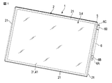
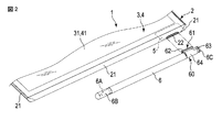
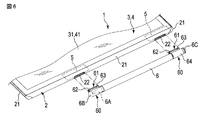
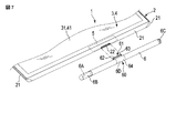
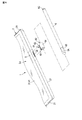
以上のように、入力装置4としてタッチパネルを筐体2に内蔵した電子機器1の入力面41に対する入力操作をするためのペン6を使用しない場合には、ペン6を筐体2に取り付けておく。本実施形態では、アンテナ5が内蔵された筐体2の外周縁21に、入力面41に沿う方向へ外周縁21に開口した係合孔22を設け、この係合孔22に着脱自在に嵌合する合成樹脂製の挿入片61をペン6の側部に設ける。挿入片61は、ペン6の軸方向に沿う係合孔22よりも小さく、入力面41を横切る方向に係合孔22に対して弾性変形して嵌合する厚みを有している。そして、挿入片61の厚みよりも小さい距離にアンテナ5に接近する位置まで入力面41に沿って外周縁21を横切る方向へ挿入片61を係合孔22に差し込むことで、ペン6を筐体2に着脱可能に固定する。
As described above, when the
Claims (5)
前記筐体の前記外周縁に沿って配置された状態で、前記係合孔に着脱自在に嵌合する合成樹脂製の挿入片を有し、前記入力面に対する入力操作に使用されるペンと、
前記筐体の前記外周縁の内側に配置され、前記入力面を横切る方向に沿う前記挿入片の寸法よりも小さい距離で前記挿入片に隣接するアンテナと、
を備え、
前記挿入片は、
前記ペンの胴部に取り付けられた保持具の基部から前記ペンの径方向に延びるとともに、前記筐体の前記外周縁に沿う方向の寸法が前記係合孔の開口寸法よりも小さい胴部と、
前記胴部に連続するとともに、前記入力面を横切る方向に沿う寸法が前記係合孔の開口寸法より大きい先端部と、
を有する電子機器。 A housing having an input surface, an outer peripheral edge positioned around the input surface, and an engagement hole opened in the outer peripheral edge in a direction along the input surface ;
Wherein in a state in which the outer is peripheral arranged along the housing has the engagement hole to be fitted detachably synthetic resin insert strip, and a pen that is used to input operation to the input surface,
An antenna disposed inside the outer periphery of the housing and adjacent to the insertion piece at a distance smaller than the dimension of the insertion piece along the direction across the input surface;
Equipped with a,
The insertion piece is
A body part extending in a radial direction of the pen from a base part of a holder attached to the body part of the pen and having a dimension in a direction along the outer peripheral edge of the housing smaller than an opening dimension of the engagement hole;
A tip portion that is continuous with the body portion and that has a dimension along the direction crossing the input surface is larger than the opening size of the engagement hole;
Electronic equipment having
前記筐体の外周縁に前記入力装置の入力面に沿う方向に開口された係合孔に着脱自在に嵌合する合成樹脂製の挿入片を備え、前記挿入片が前記係合孔に挿入された状態では、前記係合孔の近傍で前記筐体の内部に配置されたアンテナに隣接して前記入力面を横切る方向に沿う前記挿入片の寸法よりも小さい位置に前記挿入片が配置され、
前記挿入片は、
前記ペンの胴部に取り付けられた保持具の基部から前記ペンの径方向に延びるとともに、前記筐体の前記外周縁に沿う方向の寸法が前記係合孔の開口寸法よりも小さい胴部と、
前記胴部に連続するとともに、前記入力面を横切る方向に沿う寸法が前記係合孔の開口寸法より大きい先端部と、
を有するペン。 A pen for performing an input operation on an electronic device with a built-in input device,
A synthetic resin insertion piece is provided in the outer peripheral edge of the housing so as to be detachably fitted in an engagement hole opened in a direction along the input surface of the input device, and the insertion piece is inserted into the engagement hole. In the state, the insertion piece is arranged at a position smaller than the dimension of the insertion piece along the direction crossing the input surface adjacent to the antenna arranged inside the housing in the vicinity of the engagement hole,
The insertion piece is
A body part extending in a radial direction of the pen from a base part of a holder attached to the body part of the pen and having a dimension in a direction along the outer peripheral edge of the housing smaller than an opening dimension of the engagement hole;
A tip portion that is continuous with the body portion and that has a dimension along the direction crossing the input surface is larger than the opening size of the engagement hole;
With pen.
前記筐体は、前記入力装置の入力面の周囲に位置された外周縁と、前記入力面に沿う方向に前記外周縁に開口された係合孔と、を有し、
前記ペンは、前記係合孔に着脱自在に嵌合する合成樹脂製の挿入片を側部に有するとともに、前記挿入片は、前記係合孔に対し前記入力面を横切る方向に弾性変形して嵌合する先端部を有し、
前記挿入片の前記先端部が前記挿入片の厚みよりも小さい距離で前記アンテナに接近する位置まで前記挿入片を前記入力面に沿って前記係合孔に差し込むことで、前記ペンを前記筐体の外周縁に沿うように前記筐体に固定するようにしたペンの保持方法。 A holding method of attaching an input device and a pen for performing an input operation to an electronic device having an antenna built in the housing to the housing,
The housing has an outer peripheral edge located around the input surface of the input device, and an engagement hole opened in the outer peripheral edge in a direction along the input surface,
The pen has a synthetic resin insertion piece detachably fitted in the engagement hole at a side portion, and the insertion piece is elastically deformed in a direction crossing the input surface with respect to the engagement hole. Having a tip to fit,
By inserting the insertion piece into the engagement hole along the input surface until the tip of the insertion piece approaches the antenna at a distance smaller than the thickness of the insertion piece, the pen is moved to the housing. A method of holding a pen that is fixed to the casing along the outer peripheral edge of the pen.
Priority Applications (2)
| Application Number | Priority Date | Filing Date | Title |
|---|---|---|---|
| JP2015196021A JP6586341B2 (en) | 2015-10-01 | 2015-10-01 | Electronic device, pen, and pen holding method |
| US15/279,206 US10198090B2 (en) | 2015-10-01 | 2016-09-28 | Electronic apparatus with touch screen, pen for touch screen and pen retention method |
Applications Claiming Priority (1)
| Application Number | Priority Date | Filing Date | Title |
|---|---|---|---|
| JP2015196021A JP6586341B2 (en) | 2015-10-01 | 2015-10-01 | Electronic device, pen, and pen holding method |
Publications (3)
| Publication Number | Publication Date |
|---|---|
| JP2017069867A JP2017069867A (en) | 2017-04-06 |
| JP2017069867A5 true JP2017069867A5 (en) | 2018-10-25 |
| JP6586341B2 JP6586341B2 (en) | 2019-10-02 |
Family
ID=58447848
Family Applications (1)
| Application Number | Title | Priority Date | Filing Date |
|---|---|---|---|
| JP2015196021A Active JP6586341B2 (en) | 2015-10-01 | 2015-10-01 | Electronic device, pen, and pen holding method |
Country Status (2)
| Country | Link |
|---|---|
| US (1) | US10198090B2 (en) |
| JP (1) | JP6586341B2 (en) |
Families Citing this family (39)
| Publication number | Priority date | Publication date | Assignee | Title |
|---|---|---|---|---|
| JP6586341B2 (en) * | 2015-10-01 | 2019-10-02 | Dynabook株式会社 | Electronic device, pen, and pen holding method |
| AU2016100745B4 (en) | 2016-05-24 | 2019-02-21 | Stm Management Pty Ltd | A case for a tablet shaped device and a method for making a case for a tablet shaped device. |
| WO2018017118A1 (en) * | 2016-07-22 | 2018-01-25 | Hewlett-Packard Development Company, L.P. | Pen holding devices |
| USD811409S1 (en) * | 2016-11-09 | 2018-02-27 | Getac Technology Corporation | Pen loop for mobile computer |
| USD897346S1 (en) * | 2018-05-30 | 2020-09-29 | Google Llc | Stylus loop assembly including a stylus loop, stylus, and computer |
| USD887415S1 (en) | 2018-05-30 | 2020-06-16 | Google Llc | Adjustable folio |
| USD878376S1 (en) | 2018-05-30 | 2020-03-17 | Google Llc | Convertible laptop computer |
| US11392171B2 (en) | 2018-08-21 | 2022-07-19 | Speculative Product Design, Llc | Holder for mobile electronic device |
| JP1651053S (en) * | 2019-02-25 | 2020-01-27 | ||
| WO2020222729A1 (en) * | 2019-04-29 | 2020-11-05 | Hewlett-Packard Development Company, L.P. | Device accessories with attachment slots |
| USD916708S1 (en) * | 2019-07-24 | 2021-04-20 | Huazhe Ke | Case for a tablet computer |
| US11714501B2 (en) | 2019-07-25 | 2023-08-01 | Hewlett-Packard Development Company, L.P. | Digital pen holder |
| USD900113S1 (en) * | 2019-07-30 | 2020-10-27 | Songshan PAN | Tablet case |
| USD928166S1 (en) * | 2019-08-19 | 2021-08-17 | Liangwu Hu | Tablet case |
| CN110727365B (en) * | 2019-09-17 | 2023-10-10 | 苏州佳世达电通有限公司 | Tool insertion structure and electronic device |
| USD906336S1 (en) * | 2019-12-12 | 2020-12-29 | Shenzhen Baishanchuan Technology Co., Ltd | Tablet case |
| USD886109S1 (en) * | 2019-12-18 | 2020-06-02 | Dongguan Gangyuan Technology Co., Ltd. | Protective case for tablet |
| USD906337S1 (en) * | 2019-12-26 | 2020-12-29 | Ganhua Cheng | Tablet case |
| US11275455B2 (en) * | 2020-02-12 | 2022-03-15 | Apple Inc. | Mountable tool computer input |
| CN113381163B (en) * | 2020-02-25 | 2023-11-10 | 华为技术有限公司 | terminal |
| USD898035S1 (en) * | 2020-04-15 | 2020-10-06 | Ying Xu | Tablet case |
| KR20210142894A (en) * | 2020-05-19 | 2021-11-26 | 삼성전자주식회사 | Electronic device inlcuding pen input device |
| USD918924S1 (en) * | 2020-06-15 | 2021-05-11 | Ying Xu | Tablet case |
| USD943590S1 (en) * | 2020-06-26 | 2022-02-15 | Speculative Product Design, Llc | Electronic case with handle |
| USD931288S1 (en) * | 2020-07-23 | 2021-09-21 | Jiao Li | Protective cover for tablet |
| USD917493S1 (en) * | 2020-09-10 | 2021-04-27 | Hualin Zhang | Protective case for tablet PC with stand |
| JP2022074796A (en) * | 2020-11-05 | 2022-05-18 | レノボ・シンガポール・プライベート・リミテッド | Electronic device and information device system |
| WO2022103062A1 (en) * | 2020-11-10 | 2022-05-19 | 삼성전자 주식회사 | Electronic device comprising antenna and stylus pen |
| US11962711B2 (en) | 2020-11-10 | 2024-04-16 | Samsung Electronics Co., Ltd. | Electronic device including antenna and stylus pen |
| USD946578S1 (en) * | 2021-04-26 | 2022-03-22 | Ganhua Cheng | Tablet case |
| USD972574S1 (en) * | 2021-05-06 | 2022-12-13 | Dongguan Gangyuan Technology Co., Ltd. | Protective case for tablet |
| USD950566S1 (en) * | 2021-06-28 | 2022-05-03 | Huizhen Chen | Tablet cover |
| USD962949S1 (en) * | 2021-07-30 | 2022-09-06 | Zhaohong Xu | Portable electronic device case |
| USD956766S1 (en) * | 2021-08-06 | 2022-07-05 | Shenzhen Laudtec Electronics Co., Ltd. | Protective case for tablet computer |
| USD1023011S1 (en) * | 2021-08-11 | 2024-04-16 | Hai Wu | Mobile device case |
| US11324294B1 (en) * | 2021-10-29 | 2022-05-10 | Pioneer Square Brands, Inc. | Case for portable electronic computing device |
| USD1033439S1 (en) * | 2022-08-24 | 2024-07-02 | Shaogang Cheng | Tablet case |
| USD1002622S1 (en) * | 2023-03-09 | 2023-10-24 | Shenzhen Zhexin Technology Co., Ltd. | Stylus for touch screens |
| USD995534S1 (en) * | 2023-04-24 | 2023-08-15 | Shilin Yu | Tablet computer case |
Family Cites Families (16)
| Publication number | Priority date | Publication date | Assignee | Title |
|---|---|---|---|---|
| JPH10187327A (en) | 1996-12-19 | 1998-07-14 | Seiko Instr Inc | Housing mechanism for input pen |
| JP2972702B2 (en) * | 1998-03-17 | 1999-11-08 | 静岡日本電気株式会社 | Pen input type portable information terminal |
| JP2001022509A (en) * | 1999-07-12 | 2001-01-26 | Sharp Corp | Input pen holding structure and information terminal device |
| JP2001142625A (en) * | 1999-11-16 | 2001-05-25 | Kenwood Corp | Electronic equipment |
| JP2002323952A (en) * | 2001-04-24 | 2002-11-08 | Kyocera Corp | Portable terminal equipment |
| TW537454U (en) * | 2002-05-14 | 2003-06-11 | High Tech Comp Corp | Stylus-accommodating structure for wireless communication apparatus |
| JP4462011B2 (en) * | 2004-11-01 | 2010-05-12 | 日本電気株式会社 | Mobile terminal device with TV function and TV antenna / input pen |
| KR100830218B1 (en) * | 2006-12-15 | 2008-05-16 | 세원텔레텍 주식회사 | Antenna with a stylus-pen |
| CN201509213U (en) * | 2009-08-11 | 2010-06-16 | 中兴通讯股份有限公司 | Mobile communication terminal and mobile communication terminal housing provided with antennae |
| KR101787750B1 (en) * | 2010-12-01 | 2017-10-19 | 삼성전자주식회사 | Capacitive stylus pen |
| US9268379B2 (en) * | 2012-07-27 | 2016-02-23 | Hewlett-Packard Development Company, L.P. | Stylus and holder device associated therewith |
| KR101940565B1 (en) * | 2012-08-02 | 2019-01-21 | 삼성전자주식회사 | Stylus pen and electronic device having the same |
| US9596914B2 (en) * | 2013-04-19 | 2017-03-21 | Joseph A. Zaloom | Tablet transformer |
| US10222879B2 (en) * | 2015-03-31 | 2019-03-05 | Microsoft Technology Licensing, Llc | Interlocking integrated battery structure for an electronic stylus |
| KR20170033633A (en) * | 2015-09-17 | 2017-03-27 | 삼성전자주식회사 | Pen and electronic device therewith |
| JP6586341B2 (en) * | 2015-10-01 | 2019-10-02 | Dynabook株式会社 | Electronic device, pen, and pen holding method |
-
2015
- 2015-10-01 JP JP2015196021A patent/JP6586341B2/en active Active
-
2016
- 2016-09-28 US US15/279,206 patent/US10198090B2/en active Active
Similar Documents
| Publication | Publication Date | Title |
|---|---|---|
| JP2017069867A5 (en) | ||
| USD723792S1 (en) | Ear tip assembly kit | |
| JP6586341B2 (en) | Electronic device, pen, and pen holding method | |
| USD716783S1 (en) | Slim case | |
| USD772239S1 (en) | Portable electronic device with graphical user interface | |
| USD697905S1 (en) | Case for electronic device | |
| IL279898A (en) | Coupling a pen device to a companion device based on pen proximity | |
| USD714665S1 (en) | Electronic data device | |
| USD704693S1 (en) | Case for electronic device | |
| GB2558692A8 (en) | Connector assembly for an electronic device | |
| USD759246S1 (en) | Biopsy device | |
| USD791936S1 (en) | Surgical shield device | |
| USD759050S1 (en) | Display screen or portion thereof with graphical user interface | |
| USD717342S1 (en) | Electronic device | |
| JP2015511836A5 (en) | ||
| USD717836S1 (en) | One-piece centralizer with an axial seam and end-collar tabs | |
| USD717837S1 (en) | One-piece centralizer with an axial seam | |
| USD747720S1 (en) | Input pen for electronic device | |
| USD751199S1 (en) | Biopsy device | |
| USD716511S1 (en) | High temperature tool pad | |
| JP2015149176A5 (en) | ||
| JP2016137122A5 (en) | ||
| MX352561B (en) | Fastener. | |
| EP2985120A3 (en) | Tool pen with detachable function | |
| USD858758S1 (en) | Electronic device case with stethoscope |