JP2017062016A - Damper device - Google Patents
Damper device Download PDFInfo
- Publication number
- JP2017062016A JP2017062016A JP2015188704A JP2015188704A JP2017062016A JP 2017062016 A JP2017062016 A JP 2017062016A JP 2015188704 A JP2015188704 A JP 2015188704A JP 2015188704 A JP2015188704 A JP 2015188704A JP 2017062016 A JP2017062016 A JP 2017062016A
- Authority
- JP
- Japan
- Prior art keywords
- damper device
- shaft
- damper
- opening
- force
- Prior art date
- Legal status (The legal status is an assumption and is not a legal conclusion. Google has not performed a legal analysis and makes no representation as to the accuracy of the status listed.)
- Granted
Links
Images


Landscapes
- Pivots And Pivotal Connections (AREA)
Abstract
【課題】本発明は、開放部を開放する際の製品本体の傾斜角度に合わせてダンパー力を適切に制御するダンパー装置を提供する。
【解決手段】固定筐体と、固定筐体の一端にシャフトにより回動可能に軸支され固定筐体に対して開閉自在に開閉する可動筐体とを有する開閉機構に搭載されるダンパー装置であって、可動筐体の開放力に対する減衰力開始位置が、開閉機構の傾斜角度によって変化する。
【選択図】図4The present invention provides a damper device that appropriately controls a damper force in accordance with an inclination angle of a product body when an opening portion is opened.
A damper device mounted on an opening / closing mechanism having a fixed casing and a movable casing pivotally supported by a shaft at one end of the fixed casing so as to be opened and closed with respect to the fixed casing. Thus, the damping force start position with respect to the opening force of the movable casing changes depending on the inclination angle of the opening / closing mechanism.
[Selection] Figure 4
Description
本発明は、携帯用の製品の開閉機構に搭載されるダンパー装置に関する。 The present invention relates to a damper device mounted on a portable product opening / closing mechanism.
従来から、固定筐体(以下、基部とも云う)と可動筐体(以下、開放部とも云う)を備える製品においては、開放部を開閉させる開閉機構が備えられている。そうした開閉機構には、開放部の開放動作をならしめる弾性体と、弾性体による開放力(付勢力)を減衰させるダンパー装置とが具備されている。 2. Description of the Related Art Conventionally, products including a fixed housing (hereinafter also referred to as a base) and a movable housing (hereinafter also referred to as an opening) have been provided with an opening / closing mechanism that opens and closes the opening. Such an opening / closing mechanism includes an elastic body that smoothes the opening operation of the opening and a damper device that attenuates the opening force (biasing force) by the elastic body.
そうしたダンパー装置として、例えば、円筒状の固定ケース内に配置された可動軸(シャフト)に、複数の固定板と、可動軸と嵌合するカム部を有する複数の可動板と、コイルばねが挿通されて成る構成が知られている。複数の固定板と可動板とは互い違いに配置され両者はコイルばねにより弾接されている。複数の可動板は可動軸と嵌合するカム部の配置角度がそれぞれずらされて配置されている。開放部が閉状態から開状態へ移動するにしたがって、可動軸に嵌合される可動板が増えていくことで、ダンパー力を段階的に増加させる構成とされている(例えば、特許文献1参照)。 As such a damper device, for example, a movable shaft (shaft) disposed in a cylindrical fixed case is inserted with a plurality of fixed plates, a plurality of movable plates having cam portions fitted to the movable shaft, and coil springs. The structure which is made is known. The plurality of fixed plates and movable plates are alternately arranged, and both are elastically contacted by a coil spring. The plurality of movable plates are arranged such that the arrangement angles of the cam portions fitted to the movable shaft are shifted. As the opening portion moves from the closed state to the open state, the number of movable plates fitted to the movable shaft increases, so that the damper force is increased stepwise (see, for example, Patent Document 1). ).
上記の技術は、開放部に作用するダンパー力を、開放部が開放されていくに従って段階的に増加させて穏やかな開操作を実現できると記載されている。また、段階的に増加されるダンパー力は、可動軸に嵌合される可動板の枚数によって一義的に決定されている。更に、ダンパー力が作用する開始位置は、最初の可動板と可動軸との嵌合位置であり、上記特許文献1では開放部が閉状態から50°に開いた(回転した)位置である。
It is described that the above technique can realize a gentle opening operation by gradually increasing the damper force acting on the opening as the opening is opened. Further, the damper force that is gradually increased is uniquely determined by the number of movable plates fitted to the movable shaft. Furthermore, the starting position where the damper force acts is the first fitting position between the movable plate and the movable shaft. In
ところで、開放部の開く力は、開放部を開放する際の製品本体(開閉機構を含む)の状態(傾斜角度)によって異なる。特に利用者が携帯するような製品においては、開放時における製品本体の傾斜角度は利用者の状況によって様々に変化する。そのため、傾斜角度によっては必要なダンパー力を得られない場合がある。 By the way, the opening force of the opening portion varies depending on the state (inclination angle) of the product main body (including the opening / closing mechanism) when the opening portion is opened. Particularly in a product that is carried by a user, the inclination angle of the product body at the time of opening varies depending on the situation of the user. Therefore, the required damper force may not be obtained depending on the inclination angle.
例えば、ロック付きの開放部(蓋部)を有する携帯用の飲料用容器に上記のダンパー装置を適用した場合を例に取って説明する。 For example, the case where the above-described damper device is applied to a portable beverage container having an open portion (lid portion) with a lock will be described as an example.
利用者が製品本体を垂直状態から開放部の開放方向側に傾斜させた状態で開放部のロックを解除すると、弾性体の開放力(付勢力)と重力とが相まって、開放部は勢いよく開放する。その際、開放部などに付着した液体が飛び散る虞がある。特許文献1では、開放0°から50°まではダンパー力が作用しないため、開放部の開く力は相当に強くなる。
When the user releases the lock of the opening part while tilting the product body from the vertical state to the opening direction side of the opening part, the opening part is released vigorously due to the release force (biasing force) of the elastic body and gravity. To do. At that time, there is a possibility that the liquid adhering to the open part or the like may be scattered. In
また、ファンデーションなどの収容物を収納するロック付きの携帯用のコンパクトケースに上記ダンパー装置を適用した場合、開放部の開放方向側に傾斜させた状態でロック解除すると、やはり開放部が勢いよく開放してしまう。その際、収容物が飛び出たり、製品本体が利用者の手から離れたりする虞がある。 In addition, when the above damper device is applied to a portable compact case with a lock for storing things such as foundations, if the lock is released while tilted toward the opening direction of the opening, the opening will still open. Resulting in. At that time, there is a risk that the contents may jump out or the product body may be separated from the user's hand.
端的に云うと、従来のダンパー装置は、ダンパー力を一義的に制御するものであり、開放部を開放する際の製品本体(開閉機構を含む)の傾斜角度に合わせてダンパー力を適切に制御する構成ではなかった。そのため、充分なダンパー力が得られないなどの不具合が生じてしまうという課題があった。 In short, the conventional damper device uniquely controls the damper force, and appropriately controls the damper force according to the inclination angle of the product body (including the opening / closing mechanism) when opening the opening. It was not the composition to do. For this reason, there is a problem in that a problem such as a failure to obtain a sufficient damper force occurs.
本発明の一つの実施形態の目的は、上記課題点を鑑みてなされたものであり、開放部を開放する際の製品本体の傾斜角度に合わせてダンパー力を適切に制御するダンパー装置を提供することにある。 An object of one embodiment of the present invention is made in view of the above-described problems, and provides a damper device that appropriately controls a damper force according to an inclination angle of a product main body when an opening portion is opened. There is.
上記の課題は、
固定筐体と、前記固定筐体の一端にシャフトにより回動可能に軸支され前記固定筐体に対して開閉自在に開閉する可動筐体とを有する開閉機構に搭載されるダンパー装置であって、
前記ダンパー装置は、
前記可動筐体の開放力に対する減衰力開始位置が、前記開閉機構の傾斜角度によって変化することを特徴とするダンパー装置により解決できる。
The above issues
A damper device mounted on an opening / closing mechanism having a fixed casing and a movable casing that is pivotally supported by a shaft at one end of the fixed casing and that opens and closes with respect to the fixed casing. ,
The damper device is
This can be solved by a damper device in which the damping force start position with respect to the opening force of the movable casing changes depending on the inclination angle of the opening / closing mechanism.
本発明の一形態によれば、開放部を開放する際の製品本体(開閉機構を含む)の傾斜角度に合わせてダンパー力を適切に制御して、充分なダンパー力が得られないなどの不具合を解消するダンパー装置を提供できる。 According to one aspect of the present invention, the damper force is appropriately controlled according to the inclination angle of the product main body (including the opening / closing mechanism) when the opening portion is opened, so that a sufficient damper force cannot be obtained. Can be provided.
次に、本発明に係るダンパー装置の実施形態を説明する。各図面中、同一又は相当する部分には同一の符号を付しており、その重複説明は適宜簡略化ないし省略する。図面は、部材もしくは部品間の相対比を示すことを目的としない。したがって、具体的な寸法は、以下の限定的でない実施形態に照らし、当業者により決定することができる。以下、本発明に係るダンパー装置を、開閉機構を備えた携帯用のロック付き飲料用容器に適用した例を示すが、この限りではなく、蓋体などの開放部を開閉させる開閉機構が備えられた製品全般に適用可能である。特には、携帯用の製品に適用されることが好ましい。 Next, an embodiment of a damper device according to the present invention will be described. In the drawings, the same or corresponding parts are denoted by the same reference numerals, and redundant description thereof will be simplified or omitted as appropriate. The drawings are not intended to show the relative ratio between members or parts. Accordingly, specific dimensions can be determined by one skilled in the art in light of the following non-limiting embodiments. Hereinafter, an example in which the damper device according to the present invention is applied to a portable beverage container with a lock provided with an opening / closing mechanism is shown. However, the present invention is not limited thereto, and an opening / closing mechanism for opening / closing an opening part such as a lid is provided. Applicable to all products. In particular, it is preferably applied to portable products.
[第1の実施形態]
以下、図面に基づいて第1の実施形態に係るダンパー装置が適用されたロック付き飲料用容器の栓体の構成を簡単に説明する。
[First Embodiment]
Hereinafter, a configuration of a stopper for a beverage container with a lock to which the damper device according to the first embodiment is applied will be briefly described with reference to the drawings.
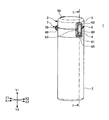
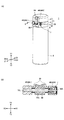
図1は、ダンパー装置が適用されたロック付き飲料用容器の一例を示す全体斜視図である。図2は、ダンパー装置が適用されたロック付き飲料用容器の一例を示す断面図である。更に云うと、図1のI−I矢視断面図である。図3Aは、ダンパー装置が適用されたロック付き飲料用容器の一例を示す背面図である。図3Bは、図3AのII−II矢視断面図である。 FIG. 1 is an overall perspective view showing an example of a beverage container with a lock to which a damper device is applied. FIG. 2 is a cross-sectional view illustrating an example of a beverage container with a lock to which the damper device is applied. Further, it is a cross-sectional view taken along the line II in FIG. FIG. 3A is a rear view illustrating an example of a beverage container with a lock to which the damper device is applied. 3B is a cross-sectional view taken along the line II-II in FIG. 3A.
<全体構成>
先ず、ロック付き飲料用容器1(以下、単に飲料用容器1と云う)の全体構成を説明する。
<Overall configuration>
First, the overall configuration of a
携帯型の飲料用容器1は、片手で持てる大きさの金属製の容器本体2と、該容器本体2の上部開口部である開口端部2Aに被着される合成樹脂製の栓体3とを備えている。容器本体2は、断熱二重構造で、上部外周には、栓体3を螺着するための雄螺子(不図示)が形成されている。栓体3は、以下に説明する開閉機構を有している。
A
栓体3は、容器本体2の開口端部2Aに着脱可能に装着される栓本体4(固定筐体に相当)と、栓本体4の一端(矢印Z1側)に本実施形態に係るダンパー装置7を構成するシャフト70により軸支され、栓本体4の上部開口部を開閉自在に開閉する蓋体5(可動筐体に相当)と、栓本体4の他端(矢印Z2側)で蓋体5を閉状態に保持するロック機構6を有している。
The
栓本体4は、一側(矢印Z1側)箇所においてシャフト70を介して蓋体5が回動自在に結合されている。即ち、栓本体4の一側(矢印Z1側)に設けられた左右一対の取付部40(40R、40L)と、蓋体5の一側(矢印Z1側)に設けられた取付部50とがシャフト70を介して回動自在に結合されている。左右一対の取付部40は、シャフト70を挿通可能な中空部をそれぞれ有している。当該中空部は水平方向に(矢印X1−X2方向)延在している。
The
取付部50は蓋体5の上下方向(矢印Y1−Y2方向)に延在し、下端は栓本体4の左右一対の取付部40の間に配置され、取付部40との組み合わせがT字形状となる構成とされている。取付部50の下方側(矢印Y2側)にはシャフト70を挿通可能な中空部を有している。
The
シャフト70は連結ピンであり、左右一対の取付部40(40R、40L)と取付部50に共通して設けられた水平方向(矢印X1−X2方向)の中空部内にシャフト70が挿通されて、蓋体5の開閉動作が可能になる。
The
前記シャフト70には、左右の取付部40(40R、40L)と取付部50との間にねじりばね30(トーションバネ)が連結されており、ねじりばね30により蓋体5が常に開方向に付勢される。勿論、ねじりばね30ではなく、他の弾性体を用いても良い。
A torsion spring 30 (torsion spring) is connected to the
前記した左右一対の取付部40(40R、40L)のうち、いずれか一方の取付部40の中空部には、本実施形態に係るダンパー装置7を搭載している。図3では矢印X1側(右側)の取付部40Rの中空部にダンパー装置7を搭載している。ダンパー装置7については後述する。図示例の取付部40Rの中空部は、矢印X2側(左側)の取付部40Lより大きな径を有しているが、この限りではない。
The
栓本体4と蓋体5の内部には、図示することは省略したが飲み口部材などが配置されて良い。
Although not shown in the figure, a mouthpiece member or the like may be disposed inside the
栓体3のシャフト70と径方向に対向する位置である他端側(矢印Z2側)には、蓋体5を係合して閉状態に保持するロック機構6が設けられている。
On the other end side (arrow Z2 side) that is a position facing the
ロック機構6は、開閉ボタン60と、開閉ボタン60の外周縁に配置されるフレーム部61、62を有している。
The lock mechanism 6 includes an open /
フレーム部61は、栓本体4の他端側(矢印Z2側)に設けられ、フレーム部62は蓋体5の他端側(矢印Z2側)に設けられている。蓋体5の閉鎖時において、フレーム部61とフレーム部62は開閉ボタン60の外周縁を囲む枠体を形成する。
The
フレーム部61の上部には、シャフト70と平行に配置される接合軸63を挿通させる貫通孔が設けられている。
A through-hole through which a joining
開閉ボタン60は、略中央位置に設けられた貫通孔(不図示)に挿通される接合軸63に軸支され、上下端部が可動するシーソー式であり、栓本体4の内外方向(矢印Z1−Z2方向)に進退可能に取り付けられ、上部に蓋体5に設けられた係合片51と着脱可能に係合する係合部64を有している(図2参照)。
The open /
開閉ボタン60の下方位置には、略円形のボタン操作部65が設けられている。ボタン操作部65の裏面側(矢印Z1側)には、復帰用弾性体であるスプリング材66が収納されている。このスプリング材66により係合部64が常時蓋体5のロック状態方向に付勢される。したがって、利用者が開閉ボタン60のボタン操作部65を押圧すると、下端部が矢印Z1方向へ押し込まれ、シーソーの原理で上端部の係合部64が矢印Z2方向に移動することで蓋体5の係合片51との係合が解除され、蓋体5が開く(開放される)。
A substantially circular
上記構成の飲料用容器1は、開閉ボタン60のボタン操作部65が押圧操作されると、ロックが解除され、シャフト70に設けられたねじりばね30の開方向への付勢力により蓋体5が自動的に開放されるものである。その際、ねじりばね30による開方向への力が強すぎると、蓋体5に付着した液体などが飛び散る虞があるため、開放力を適切に減衰させる必要がある。蓋体5の開く力は、蓋体5を開放する際の飲料用容器1(開閉機構を含む)の傾斜角度によって異なる。
When the
以下、蓋体5を開放する際の飲料用容器1の傾斜角度に合わせてダンパー力(減衰力)を適切に制御するダンパー装置7の構成について具体的に説明する。
Hereinafter, the configuration of the
(ダンパー装置)
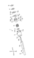
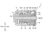
本実施形態に係るダンパー装置7の構成を図4〜図6に基づいて説明する。図4は、ダンパー装置7を一側から見た分解斜視図である。正確には図3Aの矢印Z1側から見た分解斜視図である。図5は、ダンパー装置7を他側から見た分解斜視図である。正確には図3Aの矢印Z2側から見た分解斜視図であり、且つ図4のダンパー装置7を90°右回転(時計回り)させた状態の分解斜視図である。図6は、ダンパー装置7の断面図である。
(Damper device)
A configuration of the
ダンパー装置7を構成する部材は、円筒状の収納体71内に収納される構成である。
ダンパー装置7を構成するシャフト70は、取付部50の中空部に配置される中心軸部70Sと、矢印X1側(右側)に延在し収納体71内に配置されるダンパー軸部70Rと、矢印X2側(左側)に延在し、取付部40Lの中空部に配置される支持軸部70Lを有している。勿論、収納体71が配置されるのはダンパー軸部70Rの限りではなく、支持軸部70L側であって良い。中心軸部70Sは、取付部50へ挿通可能な切欠き平坦面を有し、当該切欠き平坦面の一側(矢印X1方向)端部に抜け止め防止用の段部が設けられて良い。
The members configuring the
The
ダンパー軸部70Rは、収納体71の底部に設けられた貫通孔71Aへ回転可能に挿入され、収納体71内を貫通する。
The
ダンパー装置7は、収納体71の底部から矢印X1方向に、摺動体72、弾性部73、被係止部74、係止部75、固定板76、摺動体77、リベットプレート78を有している。摺動体72、弾性部73、固定板76、リベットプレート78は金属製が好ましく、被係止部74、係止部75、摺動体77は、樹脂製が好ましい。
The
摺動体72、被係止部74、リベットプレート78は、ダンパー軸部70Rに軸回転可能に支持(軸支)されている。また、弾性部73、係止部75、固定板76、摺動体77は、被係止部74の胴体部741に軸支される構成である。
The sliding
固定板76の外周には外方へ突出する突起部76Aが設けられ、この突起部76Aが収納体71のスリット71B内に挿入されて、固定板76がシャフト70の回転と同期せず、且つ収納体71内の軸方向(矢印X1−X2方向)へ移動可能に収納される。
A protruding
摺動体72と摺動体77は、表面が平滑な金属製又は樹脂などの部材で、部材間の摩擦を防止する緩衝板としての機能を発揮する。
The sliding
次に、ダンパー力(減衰力)を発生させる構成を説明する。ダンパー力は、特に被係止部74、係止部75により発生される。
Next, a configuration for generating a damper force (damping force) will be described. The damper force is generated particularly by the locked
被係止部74は、中空部を有する筒形形状の胴体部741と、当該胴体部741の外周面の略中央位置に設けられるフランジ部742を有している。
The locked
被係止部74は、胴体部741の中空部内にダンパー軸部70Rが挿通されて、ダンパー軸部70Rの回転と同期する構成とされている。胴体部741の外方側(矢印X1側)(以下、胴体部741Aという)は、係止部75、固定板76、摺動体77を軸支する。胴体部741の内方側(矢印X2側)(以下、胴体741Bという)は、コイルばねなどの弾性部73を軸支する。したがって、被係止部74は、弾性部73によりダンパー軸部70Rの軸方向(矢印X1−X2方向)に移動可能である。
The locked
被係止部74のフランジ部742の外方側(矢印X1側)には、カム受部743が設けられている。カム受部743は、シャフト70の回転方向に対して傾斜する傾斜面743Aを有している。
A
係止部75は、被係止部74の胴体部741Aの外周に回転自在に設けられる略環状部材である。係止部75は、胴体部741Aを挿通する中空部を有するリング部751と、リング部751の外周縁の一部に設けられたカム部752を有している。係止部75の重心(質量中心)は、中心をずらした位置に設けられており、本実施形態ではカム部752の位置が重心となる。したがって、回動自在な係止部75のカム部752は、重力方向に対して常に下方位置に位置する。因みに係止部75の重心は、カム部752ではなく、カム部752の近傍であって良く、カム部752が重力方向の下方位置に来るように偏っていればよい。
The locking
カム部752は、ダンパー軸部70Rの回転方向に対して傾斜する傾斜面752Aを有しており、カム受部743の傾斜面743Aと接触して干渉し合う構成である(図7B参照)。図示例の傾斜面743Aと、傾斜面752Aとは同じ角度に傾斜する様態を示したが、この限りではない。またカム部752は傾斜面を有さず、単に突起部であっても実施可能である。
The
上記したダンパー装置7の各部材の取付け構造としては、収納体71内に挿通されたダンパー軸部70Rに、矢印X1方向に摺動体72、弾性部73を胴体部741Bに取付けた被係止部74を挿通する。次に被係止部74の胴体部741Aに係止部75、固定板76、摺動体77を挿通させる。固定板76は突起部76Aを収納体71のスリット71Bに差し入れられる。最後に摺動体77から突出したダンパー軸部70Rへリベットプレート78を挿入し、かしめることでダンパー装置7をシャフト70(ダンパー軸部70R)へ取付けることができる。その後、ダンパー装置7を取付けたシャフト70を、蓋体5の取付部50と栓本体4の取付部40R、40Lの各中空部内へ挿通されて、飲料用容器1へ搭載される。
As a mounting structure of each member of the
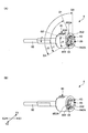
(ダンパー動作)
上記構成のダンパー装置7の係止部75と被係止部74によるダンパー力発生の基本動作を図7により説明する。図7は、係止部75と被係止部74との関係を示す一部透過斜視図であり、重力方向下方位置(矢印Y2側)から見た底面図である。Aは蓋体5の開放前の係止部75と被係止部74との関係を示している。Bは蓋体5を開放後の係止部75と被係止部74が干渉し合っている状態を示している。Aは特に云うと、飲料用容器1が垂直に起立している状態における係止部75と被係止部74との関係を示している。また、図7は説明の関係上、収納体71を省略しており、リベットプレート78も省略している。
(Damper operation)
A basic operation of generating a damper force by the locking
上記したように本実施形態のダンパー装置7は、カム受部743を有する被係止部74がシャフト70(ダンパー軸部70R)の回転と同期し、カム部752を有する係止部75がシャフト70及び被係止部74の回転と同期せず常に重力方向の下方位置にカム部752を位置させる構成を特長としている。
As described above, in the
したがって、垂直状態に起立する飲料用容器1の蓋体5の開放前は、図7Aに示すように、重力方向の下方位置に存在する係止部75のカム部752と、被係止部74のカム受部743とが干渉しない状態にある。
Therefore, before the
利用者がロック機構6の開閉ボタン60のボタン操作部65を押圧すると、ロックが解除されて、ねじりばね30によりシャフト70が反時計回りに回転して蓋体5が開方向へ回動する。シャフト70が反時計回りに回転すると、シャフト70と同期する被係止部74も反時計回りに回転する。すると、図7Bに示すように、被係止部74のカム受部743の傾斜面743Aと、係止部75のカム部752の傾斜面752Aとが接触して干渉し合う。傾斜面743Aと傾斜面752A同士が干渉し合うと、被係止部74は、弾性体73により矢印X1−X2方向へスライドしてダンパー力を制御し(図6参照)、シャフト70の開方向への力(開放力)を徐々に減衰させることができる。したがって、傾斜面743Aと傾斜面752A同士が干渉し合う位置(角度)が、減衰力開始位置(角度)となる。
When the user presses the
本実施形態のダンパー装置7は、係止部75がシャフト70及び被係止部74の回転と同期せず常に重力方向の下方位置にカム部752を位置させるため、蓋体5を開放する際の飲料用容器1の傾斜角度に合わせてダンパー力を適切に制御できる効果を奏する。
In the
以下にその点を、図8〜図10から説明する。
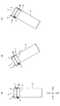
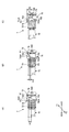
図8A〜図8Cは、蓋体5を開放する際の飲料用容器1の異なる状態(傾斜角度)を説明する側面図である。図9A〜図9Cは、蓋体5を開放する際の飲料用容器1の異なる状態(傾斜角度)における係止部と被係止部との位置関係を説明する一部透過斜視図である。10A〜図10Cは、蓋体5を開放する際の飲料用容器1の異なる状態(傾斜角度)における係止部と被係止部との位置関係を説明する一部透過底面図である。図10は重力方向下方位置(矢印Y2側)から見た図である。
This point will be described below with reference to FIGS.
8A to 8C are side views illustrating different states (inclination angles) of the
図8〜図10において各A〜Cはすべて対応した動作状態として示した。Aは飲料用容器1が垂直状態に起立している場合(傾斜角度0°)を示し、Bは飲料用容器1が起立状態から蓋体5の開放方向側(矢印Z1側)に傾斜した場合を示し、Cは飲料用容器1が起立状態から蓋体5の開放方向と逆側(矢印Z2側)に傾斜した場合を示した。また、図9、図10は説明の関係上、収納体71を省略しており、図9はリベットプレート78も省略している。
8 to 10, all of A to C are shown as corresponding operating states. A shows the case where the
因みに、飲料用容器1が図8Bに示す状態から蓋体5を開放する際には、ねじりばね30の開放力(付勢力)と重力とが相まって開放力が最も強くなる。したがって、開放直後に係止部75と被係止部74とが干渉し合ってダンパー力を発生させる必要がある。
Incidentally, when the
一方、飲料用容器1が図8Cに示す状態から蓋体5を開放する際には、ねじりばね30の開放力(付勢力)が重力と蓋体5の重量により弱まる。そのため、ダンパー力の発生を図8Aの場合(垂直状態)よりも遅くすることで蓋体5の開放をスムーズにならしめることができる。以下、飲料用容器1の状態(傾斜角度)ごとにダンパー力の開始(減衰力開始位置(角度))が制御される点を説明する。
On the other hand, when the
(垂直状態に起立している場合)
蓋体5が開放される際の飲料用容器1が、図8Aに示す垂直状態に起立している場合(傾斜角度0°)において、係止部75と被係止部74は図9A、図10Aに示す位置にある。図9Aに示すように係止部75の傾斜面752Aの傾斜開始線P1と、被係止部74の傾斜面743Aの傾斜開始線P2は、ダンパー軸部70Rに対して放射方向(半径方向)に延びており、傾斜開始線P1と傾斜開始線P2とは角度K1を有している。図10においては、傾斜開始線P1と傾斜開始線P2とは距離H1を有している。
(When standing upright)
When the
角度K1と距離H1は、蓋体5が開放されてダンパー力(係止部75と被係止部74との干渉)が開始されるまでの間隔を示す。角度K1、距離H1が大きいほどダンパー力の開始が遅く、ダンパー力が抑制されることを意味する。
The angle K1 and the distance H1 indicate an interval until the
因みに角度K1、距離H1は、ねじりばね30の弾性力や、蓋体5の大きさや重量など全体のバランスを鑑みて適切に設定される。
Incidentally, the angle K1 and the distance H1 are appropriately set in consideration of the overall balance such as the elastic force of the
(蓋体の開放方向側に傾斜した場合)
蓋体5が開放される直前の飲料用容器1が、起立状態から図8Bに示す蓋体5の開放側(矢印Z1側)に傾斜している場合において、係止部75と被係止部74は図9B、図10Bに示す位置にある。図9Bに示すように係止部75の傾斜面752Aの傾斜開始線P1と、被係止部74の傾斜面743Aの傾斜開始線P3は、ダンパー軸部70Rに対して放射方向(半径方向)に延びており、ダンパー開始線P1とダンパー開始線P3とは角度K2を有している。図10Bにおいては、ダンパー開始線P1とダンパー開始線P3とは距離H2を有している。図9A、図10Aと比較して明らかなように、角度K2と距離H2は、角度K1と距離H1に比して非常に小さく「角度K2<角度K1、距離H2<距離H1」となっている。
(When tilted toward the opening direction of the lid)
When the
したがって、ダンパー装置の係止部75と被係止部74とが、図9B、図10Bの状態で蓋体5が開放されると、開放直後に係止部75の傾斜面752Aと被係止部74の傾斜面743Aとが干渉し合いダンパー力が発生される。これは、直立状態から開放された場合(各部(A))に比してダンパー力の開始がはるかに速いことを意味する。
Therefore, when the
上記のように本実施形態のダンパー装置7は、飲料用容器1が起立状態から蓋体5の開放側に傾斜している場合、蓋体5の開放直後にダンパー力が働くため、蓋体5が勢いよく開放して蓋体5などに付着した液体が飛び散るなどの問題を防止できる。
As described above, when the
(蓋体の開放方向と逆側に傾斜した場合)
蓋体5が開放される直前の飲料用容器1が、起立状態から図8Cに示す蓋体5の開放方向と逆側(矢印Z2側)に傾斜している場合において、係止部75と被係止部74は図9C、図10Cに示す位置にある。図9Cに示すように係止部75の傾斜面752Aの傾斜開始線P1と、被係止部74の傾斜面743Aの傾斜開始線P4は、ダンパー軸部70Rに対して放射方向(半径方向)に延びており、ダンパー開始線P1とダンパー開始線P4とは角度K3を有している。図10Cにおいては、ダンパー開始線P1とダンパー開始線P4とは距離H3を有している。図9A、図10Aと比較して明らかなように、角度K3と距離H3は、角度K1と距離H1に比して大きく「角度K3>角度K1、距離H3>距離H1」となっている。
(When tilted in the direction opposite to the opening direction of the lid)
When the
したがって、ダンパー装置の係止部75と被係止部74とが、図9C、図10Cの状態で蓋体5が開放されると、各図(A)の場合よりも遅くに、係止部75の傾斜面752Aと被係止部74の傾斜面743Aとが干渉し合いダンパー力が発生される。これは、直立状態から開放された場合(各図(A))に比してダンパー力の発生がはるかに遅いことを意味する。
Therefore, when the
上記のように本実施形態のダンパー装置7は、飲料用容器1が起立状態から蓋体5の開放方向と反対側に傾斜している場合、蓋体5の開放後から十分遅くにダンパー力が働く。
As described above, in the
具体的には例えば、蓋体5が重力方向の上方位置(矢印Y1側)まで開放した後に、ダンパー力が発生されることになる。したがって、蓋体5(又はねじりばね30)の開放力が、重力と蓋体5の重量により最も弱まっている開放初期(直後)にはダンパー力が作用せず、開放力が大きくなる開放後期にはダンパー力が増加するので、蓋体5の開放がスムーズになる。
Specifically, for example, the damper force is generated after the
上記のように本実施形態のダンパー装置7は、カム受部743を有する被係止部74がシャフト70の回転と同期し、カム部752を有する係止部75がシャフト70及び被係止部74の回転と同期せず常に重力方向の下方位置にカム部752を位置させる構成とした。したがって、蓋体5が開放される際の飲料用容器1(開閉機構を含む)の状態(傾斜角度)に合わせて、適切なダンパー力に制御することができ、ダンパー力不足による不具合を防止できる。また、蓋体5の開放力を過度に減衰させること防止して、スムーズな蓋体5の開放動作に寄与できる。
As described above, in the
[第2の実施形態]
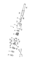
次に、第2の実施形態に係るダンパー装置8を図11から説明する。図11は、第2の実施形態に係るダンパー装置8を一側から見た分解斜視図であり、重力方向下方位置(矢印Y2側)から見た図である。
[Second Embodiment]
Next, the
本実施形態のダンパー装置8は、基本的に第1の実施形態で説明したダンパー装置7と同じ技術的思想を有しており、重複する説明は省略する。本実施形態のダンパー装置8も飲料用容器1に適用される。また、ダンパー装置8の搭載箇所やシャフトにより軸回転可能に支持される点なども第1の実施形態と同じである。図11は図3の矢印Z1側から見た分解斜視図であり、重力方向下方位置(矢印Y2側)から見た底面図である。
The
以下に、第1の実施形態との相違点について説明する。
第1の実施形態との相違点は、端的に云えば、係止部と被係止部の構成が異なる。しかし、係止部のカム部が重力方向に対して常に下方位置に配置され、シャフトの回転に伴って回転した被係止部のカム受部と干渉し合う点は同じである。
Hereinafter, differences from the first embodiment will be described.
In short, the difference from the first embodiment is the configuration of the locking portion and the locked portion. However, it is the same in that the cam portion of the locking portion is always arranged at a lower position with respect to the direction of gravity and interferes with the cam receiving portion of the locked portion that has rotated as the shaft rotates.
本実施形態のダンパー装置8を構成する部材は、円筒状の収納体81内に収納される構成である。ダンパー装置8を構成するシャフト80は、取付部50の中空部に配置される中心軸部80Sと、矢印X1側(右側)に延在し収納体81内に配置されるダンパー軸部80Rと、矢印X2側(左側)に延在し、取付部40Lの中空部に配置される支持軸部80Lを有している。中心軸部80Sは、取付部50へ挿通可能な切欠き平坦面を有し、当該切欠き平坦面の一側(矢印X1方向)端部に抜け止め防止用の段部が設けられて良い。ダンパー軸部80Rと中心軸部80Sは略同径に形成され、支持軸部80Lは小径に形成されて良い。
The members constituting the
シャフト80は、収納体81の開口部から底部に設けられた貫通孔81Aに向かって回転可能に挿入され、ダンパー軸部80Rは収納体81を貫通状態に軸支する。またダンパー軸部80Rと中心軸部80Sとの境界部には、収納体81の矢印X2方向への移動を規制する(又は取付部40Rからの抜けを防止する)止めリング86を嵌合する溝80Mが設けられている。
The
要するにダンパー装置8は、シャフト80においてダンパー軸部80Rの矢印X1側の端部から溝80Mまでの間に配置される。
In short, the
ダンパー装置8は、収納体81の底部から矢印X1方向に、弾性部82、ガイド部83、係止部84、被係止部85を有している。ガイド部83、係止部84は樹脂製が好ましい。被係止部85は金属製であることが好ましい。
The
ガイド部83は、筒形形状の胴体部831と、胴体部831の矢印X1側の端部に設けられるフランジ部832を有している。胴体部831の外周にはコイルばねなどの弾性部82が装着されている。フランジ部832は、上面に係止部84のシャフト80の回転方向の移動をガイドするガイド溝833が設けられ、側面には外方へ突起する突起部834が設けられている。この突起部834が収納体81の溝部81B内に挿入されて、ガイド部83がシャフト80の回転と同期せず、且つ収納体81内の軸方向(矢印X1−X2方向)へ移動可能に収納される。ガイド溝833は、シャフト80の回転方向に沿って形成されており、完全な円弧形状ではなく行止り端部833Aが設けられ、係止部84の移動を規制する構成である。
The
ガイド部83、被係止部85は、ダンパー軸部80Rに軸回転可能に支持されている。また、係止部84はガイド部83のフランジ部832のガイド溝833内に支持される構成である。
The
次に、ダンパー力(減衰力)を発生させる構成を説明する。ダンパー力は、特に被係止部85、係止部84により発生される。
Next, a configuration for generating a damper force (damping force) will be described. The damper force is generated particularly by the locked
被係止部85は、底部を有する筒形形状の胴体部851と、当該胴体部851の外周面に外方へ突出するカム受部852を有している。カム受部852は、矢印X2側の側面にシャフト80の回転方向に対して傾斜する傾斜面852Aを有している。係止部85は、ダンパー軸部80Rの端部(矢印X1側)とかしめによる締結がなされて、ダンパー軸部80Rの回転と同期する構成とされている。勿論、被係止部85とダンパー軸部80Rとは一体形成されて良い。
The locked
係止部84は、シャフト80の軸方向に延在する基部841と、基部841の一側端部(矢印X1側端部)にカム部842を有している。基部841は、ガイド部83のガイド溝833内に挿入され、ガイド溝833に沿って移動可能に支持される。カム部842は、矢印X1側の側面にシャフト80の回転方向に対して傾斜する傾斜面842Aを有している。係止部84の基部841は、ガイド溝833内に沿って移動可能なフリーな状態で挿入されているため、係止部84は重力方向に対して常に下方位置に配置されることになる。これは、カム部842が重力方向に対して常に下方位置に存在できることを意味する。
The locking
前記したカム部842の傾斜面842Aは、カム受部852の傾斜面852Aと接触して干渉し合う構成である。傾斜面842Aと、傾斜面852Aとは同じ角度に傾斜する様態で実施して良い。またカム受部852は傾斜面を有さず、単に突起部であっても実施可能である。
The
上記したダンパー装置8の各部材の取付け構造としては、ダンパー軸部80Rの矢印X1側端部に被係止部85がかしめ締結される。そしてダンパー軸部80Rに、弾性部82を胴体部831に取付け、ガイド溝833に係止部84の基部841を挿入したガイド部83と、収納体81を挿入する。最後に止めリング86をシャフト80の溝80Mへ装着することで、ダンパー装置8をダンパー軸部80Rへ取付けることができる。
As a mounting structure of each member of the
(ダンパー動作)
上記構成のダンパー装置8の係止部84と被係止部85によるダンパー力発生の基本動作を図12により説明する。図12は、係止部84と被係止部85との関係を示す斜視図であり、重力方向下方位置(矢印Y2側)から見た図である。Aは蓋体5の開放前の係止部84と被係止部85との関係を示している。Bは蓋体5を開放後の係止部84と被係止部85が干渉し合っている状態を示している。Aは特に云うと、飲料用容器1が垂直に起立している状態における係止部84と被係止部85との関係を示している。
(Damper operation)
A basic operation of generating a damper force by the locking
本実施形態のダンパー装置8も第1の実施形態のダンパー装置7と同様に、カム受部852を有する被係止部85がシャフト80(ダンパー軸部80R)の回転と同期し、カム部842を有する係止部84がシャフト80の回転と同期せず常に重力方向の下方位置にカム部842を位置させる構成を特長としている。
Similarly to the
したがって、垂直状態に起立する飲料用容器1の蓋体5の開放前は、図12Aに示すように、ガイド部83のガイド溝833内において重力方向の下方位置に存在する係止部84のカム部842と、被係止部85のカム受部852とが干渉しない状態にある。
Therefore, before the
利用者がロック機構6の開閉ボタン60のボタン操作部65を押圧すると、ロックが解除されてねじりばね30によりシャフト80が反時計回りに回転して蓋体5が開方向へ回動する。シャフト80が反時計回りに回転すると、シャフト80と同期する被係止部85も反時計回りに回転する。すると、図12Bに示すように、被係止部85のカム受部852の傾斜面852Aと、係止部84のカム部842の傾斜面842Aとが接触して干渉し合い、両者がガイド溝833の範囲内を移動して開放力を減衰させる。傾斜面852Aと傾斜面842A同士が干渉し合うと、ガイド部83は、弾性体82により矢印X1−X2方向へスライドしてダンパー力を制御し、シャフト80の開方向への力(開放力)を徐々に減衰させることができる。したがって、傾斜面852Aと傾斜面842A同士が干渉し合う位置(角度)が、減衰力開始位置(角度)である。
When the user presses the
本実施形態のダンパー装置8は、第1の実施形態と同様に係止部84がシャフト80の回転と同期せず常に重力方向の下方位置にカム部842を位置させるため、蓋体5を開放する際の飲料用容器1の傾斜角度に合わせてダンパー力を適切に制御できる効果を奏する。この点は図8〜図10において説明した通りであり、図示して詳細に説明することは省略する。
As in the first embodiment, the
端的に図12Aから説明する。位置Q1は、飲料用容器1が垂直状態に起立した場合(図8A参照)の被係止部85の位置である。角度J1は位置Q1に位置する被係止部85と係止部84との距離である。
Briefly, FIG. 12A will be described. The position Q1 is the position of the locked
また位置Q2は、飲料用容器1が起立状態から蓋体5の開放方向側(矢印Z1側)に傾斜した場合(図8B参照)の被係止部85の位置である。角度J2は位置Q2に位置する被係止部85と係止部84との距離である。
Further, the position Q2 is a position of the locked
位置Q3は、飲料用容器1が起立状態から蓋体5の開放方向と逆側(矢印Z2側)に傾斜した場合(図8C参照)の被係止部85の位置である。角度J3は位置Q3に位置する被係止部85と係止部84との距離である。位置Q4は係止部84(カム部842)の位置であり、係止部84は常に重力方向の下方位置に存在するため、位置Q4は変化しない。
The position Q3 is the position of the locked
図示から明らかなように角度J2は、角度J1に比して角度が小さい。つまり被係止部85と係止部84は近接位置に存在している。したがって、蓋体5の開放直後に係止部84の傾斜面842Aと被係止部85の傾斜面852Aとが干渉し合いダンパー力が発生される。これは、直立状態から開放された場合(位置Q1)に比してダンパー力の発生がはるかに速いことを意味する。
As is apparent from the drawing, the angle J2 is smaller than the angle J1. That is, the locked
上記のように本実施形態のダンパー装置8は、飲料用容器1が起立状態から蓋体5の開放側に傾斜している場合、蓋体5の開放直後にダンパー力が働くため、蓋体5が勢いよく開放して蓋体5などに付着した液体が飛び散るなどの問題を防止できる。
As described above, when the
また図示から明らかなように、角度J3は、角度J1に比して角度が大きい。つまり被係止部85と係止部84とは相当に離れている。したがって、蓋体5が開放されると、位置Q1の場合よりも遅くに、係止部84の傾斜面842Aと被係止部85の傾斜面852Aとが干渉し合いダンパー力が発生される。これは、直立状態から開放された場合(位置Q1)に比してダンパー力の発生がはるかに遅いことを意味する。
As is clear from the drawing, the angle J3 is larger than the angle J1. That is, the locked
上記のように本実施形態のダンパー装置8は、飲料用容器1が起立状態から蓋体5の開放方向と反対側に傾斜している場合、蓋体5の開放後から十分遅くにダンパー力が働く。
As described above, when the
具体的には例えば、蓋体5が重力方向の上方位置(矢印Y1側)まで開放した後に、ダンパー力が発生されることになる(図8C参照)。したがって、蓋体5(又はねじりばね30)の開放力が、重力と蓋体5の重量により最も弱まっている開放初期(直後)にはダンパー力が作用せず、開放力が大きくなる開放後期にはダンパー力が増加するので、蓋体5の開放がスムーズになる。
Specifically, for example, the damper force is generated after the
(変形例1)
第1の実施形態において、弾性部73はコイルバネであり、被係止部74の胴体部741Bの外周に装着される構成を示した。しかし、弾性部は胴体部741Bに設けられても良い。即ち、胴体部741Bに複数のスリットなどを設けて弾性力を発生させても良い。
(Modification 1)
In the first embodiment, the
(変形例2)
第2の実施形態において、弾性部82はコイルバネであり、ガイド部83の胴体部831の外周に装着される構成を示した。しかし、弾性部は胴体部831に設けられても良い。即ち、胴体部831に複数のスリットなどを設けて弾性力を発生させても良い。
(Modification 2)
In the second embodiment, the
(変形例3)
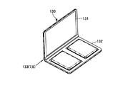
上記した実施形態では、本発明に係るダンパー装置7、8を飲料用容器1に適用した例を示したがこの限りではない。例えば図13に示すように、ファンデーションなどの収容物を収納するロック付きの携帯用のコンパクトケース130にダンパー装置7、8を適用しても良い。その際ダンパー装置7、8は、コンパクトケース130の、可動筐体131を開閉可能に固定筐体132と連結するヒンジ部133に搭載される。
(Modification 3)
In the above-described embodiment, the example in which the
(変形例4)
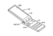
また、本発明に係るダンパー装置7、8は、図14に示す携帯電話140においても適用可能である。特に、上面に複数のキーが配列された操作部141Aなどが形成された固定筐体141と、表面にLCD等の表示部142Aなどが形成された可動筐体142を有し、可動筐体142がヒンジ部143を介して回動する開閉可能な携帯電話に適用される。その際ダンパー装置7、8は、携帯電話140のヒンジ部143に搭載される。
(Modification 4)
The
以上、本発明の好ましい実施形態について詳述したが、本発明は上記した特定の実施形態に限定されるものではなく、特許請求の範囲に記載された本発明の要旨の範囲内において、種々の変形・変更が可能なものである。 The preferred embodiments of the present invention have been described in detail above. However, the present invention is not limited to the specific embodiments described above, and various modifications are possible within the scope of the gist of the present invention described in the claims. It can be modified and changed.
1 ロック付き飲料用容器
2 容器本体
2A 開口端部
3 栓体
30 ねじりばね
4 栓本体(固定筐体)
40R、40L 取付部
5 蓋体(可動筐体)
50 取付部
51 係合片
6 ロック機構
60 開閉ボタン
61、62フレーム部
63 接合軸
64 係合部
65 ボタン操作部
66 スプリング材
7 ダンパー装置
70 シャフト
70R ダンパー軸部
70S 中心軸部
70L 支持軸部
71 収納体
71A 貫通孔
71B スリット
72 摺動体
73 弾性部
74 被係止部
741 胴体部
741A 胴体部(外方側)
741B 胴体部(内方側)
742 フランジ部
743 カム受部
743A 傾斜面
75 係止部
751 リング部
752 カム部
752A 傾斜面
76 固定板
76A 突起部
77 摺動体(緩衝体)
78 リベットプレート
8 ダンパー装置
80 シャフト
80R ダンパー軸部
80S 中心軸部
80L 支持軸部
80M 溝
81 収納体
81A 貫通孔
81B 溝部
82 弾性部
83 ガイド部
831 胴体部
832 フランジ部
833 ガイド溝
833A 行止り端部
834 突起部
84 係止部
841 基部
842 カム部
842A 傾斜面
85 被係止部
851 胴体部
852 カム受部
852A 傾斜面
86 止めリング
130 コンパクトケース
131 可動筐体
132 固定筐体
133 ヒンジ部
140 携帯電話
141 固定筐体
141A 操作部
142 可動筐体
142A 表示部
133 ヒンジ部
1 Beverage container with
40R,
50 Attaching
741B fuselage (inward side)
742
78
Claims (10)
前記可動筐体の開放力に対する減衰力開始位置が、前記開閉機構の傾斜角度によって変化することを特徴とするダンパー装置。 A damper device mounted on an opening / closing mechanism having a fixed casing and a movable casing that is pivotally supported by a shaft at one end of the fixed casing and that opens and closes with respect to the fixed casing. ,
A damper device, wherein a damping force start position with respect to an opening force of the movable casing changes depending on an inclination angle of the opening / closing mechanism.
円筒状の収納体と、
前記収納体内に回転可能に挿入された前記シャフトと、
カム部を有する係止部と、
前記シャフトの回転と同期し、前記カム部と干渉し合うカム受部を有する被係止部と、
を有し、
前記係止部の前記カム部は、重力方向に対して常に下方位置に配置され、前記シャフトの回転に伴って回転した前記被係止部の前記カム受部と干渉し合うことにより、前記可動筐体の開放力に対する減衰力を発生することを特徴とする請求項1に記載のダンパー装置。 The damper device is
A cylindrical storage body;
The shaft rotatably inserted into the storage body;
A locking portion having a cam portion;
A locked portion having a cam receiving portion that synchronizes with the rotation of the shaft and interferes with the cam portion;
Have
The cam portion of the locking portion is always disposed at a lower position with respect to the direction of gravity, and interferes with the cam receiving portion of the locked portion rotated with the rotation of the shaft, thereby moving the movable portion. The damper device according to claim 1, wherein a damping force with respect to an opening force of the housing is generated.
前記係止部は、前記シャフトの軸方向に延在する基部と、前記カム部とを有し、
前記基部は、前記ガイド溝内に配置され、当該ガイド溝に沿って移動して、前記カム部を重力方向に対して常に下方位置に配置させることを特徴とする請求項2に記載のダンパー装置。 A guide portion fixed to the housing body and having a guide groove for guiding the movement of the locking portion;
The locking portion has a base portion extending in the axial direction of the shaft, and the cam portion,
The damper device according to claim 2, wherein the base portion is disposed in the guide groove and moves along the guide groove so that the cam portion is always disposed at a lower position with respect to the direction of gravity. .
前記シャフトの回転方向に沿って形成されていることを特徴とする請求項6に記載のダンパー装置。 The guide groove is
The damper device according to claim 6, wherein the damper device is formed along a rotation direction of the shaft.
Priority Applications (1)
| Application Number | Priority Date | Filing Date | Title |
|---|---|---|---|
| JP2015188704A JP6637707B2 (en) | 2015-09-25 | 2015-09-25 | Damper device |
Applications Claiming Priority (1)
| Application Number | Priority Date | Filing Date | Title |
|---|---|---|---|
| JP2015188704A JP6637707B2 (en) | 2015-09-25 | 2015-09-25 | Damper device |
Publications (2)
| Publication Number | Publication Date |
|---|---|
| JP2017062016A true JP2017062016A (en) | 2017-03-30 |
| JP6637707B2 JP6637707B2 (en) | 2020-01-29 |
Family
ID=58430012
Family Applications (1)
| Application Number | Title | Priority Date | Filing Date |
|---|---|---|---|
| JP2015188704A Active JP6637707B2 (en) | 2015-09-25 | 2015-09-25 | Damper device |
Country Status (1)
| Country | Link |
|---|---|
| JP (1) | JP6637707B2 (en) |
Cited By (1)
| Publication number | Priority date | Publication date | Assignee | Title |
|---|---|---|---|---|
| US20210231696A1 (en) * | 2020-01-29 | 2021-07-29 | Jvckenwood Corporation | Detection apparatus and damper structure |
Citations (2)
| Publication number | Priority date | Publication date | Assignee | Title |
|---|---|---|---|---|
| JP2004259808A (en) * | 2003-02-25 | 2004-09-16 | Kenwood Corp | Panel tipping mechanism of electronic apparatus |
| JP2010019300A (en) * | 2008-07-09 | 2010-01-28 | Panasonic Corp | Damper device |
-
2015
- 2015-09-25 JP JP2015188704A patent/JP6637707B2/en active Active
Patent Citations (2)
| Publication number | Priority date | Publication date | Assignee | Title |
|---|---|---|---|---|
| JP2004259808A (en) * | 2003-02-25 | 2004-09-16 | Kenwood Corp | Panel tipping mechanism of electronic apparatus |
| JP2010019300A (en) * | 2008-07-09 | 2010-01-28 | Panasonic Corp | Damper device |
Cited By (2)
| Publication number | Priority date | Publication date | Assignee | Title |
|---|---|---|---|---|
| US20210231696A1 (en) * | 2020-01-29 | 2021-07-29 | Jvckenwood Corporation | Detection apparatus and damper structure |
| US11927599B2 (en) * | 2020-01-29 | 2024-03-12 | Jvckenwood Corporation | Detection apparatus and damper structure |
Also Published As
| Publication number | Publication date |
|---|---|
| JP6637707B2 (en) | 2020-01-29 |
Similar Documents
| Publication | Publication Date | Title |
|---|---|---|
| CN101043219B (en) | Hinge device for portable terminal | |
| JP6893688B2 (en) | Switchgear switchgear and various switchgear equipped with this switchgear switchgear | |
| US8485585B2 (en) | Push-up device | |
| JP5805419B2 (en) | Hinge device, opening / closing device, and portable device | |
| KR101338777B1 (en) | Opening-closing device of manuscript pressing plate and office machine | |
| WO2011132754A1 (en) | Cup holder | |
| KR101725720B1 (en) | Cup holder | |
| JP2020175703A (en) | Rotary holder device | |
| US7484266B1 (en) | Hinge apparatus | |
| KR101207295B1 (en) | a reading desk | |
| JP2017062016A (en) | Damper device | |
| JP2019048550A (en) | Double door storage device | |
| JP6957318B2 (en) | Stand automatic switchgear and terminal equipment using this switchgear | |
| JP6228957B2 (en) | Beverage container closure with lock | |
| JP2003120651A (en) | Hinge device and cellular phone using this hinge device | |
| JP3194179U (en) | Game toys | |
| JP2003269038A (en) | Gravity hinged door hinges | |
| CN106019877A (en) | Opening and closing support device | |
| JP2010164076A (en) | Hinge device and cellular phone using the hinge device | |
| JP2018053928A (en) | Hinge | |
| JP2016035134A (en) | Door operation assisting device | |
| JP2015068118A (en) | Door check device | |
| JP2020059458A (en) | Cup holder | |
| JP3834328B2 (en) | Mobile phone | |
| JP2005279145A (en) | Compact container |
Legal Events
| Date | Code | Title | Description |
|---|---|---|---|
| A621 | Written request for application examination |
Free format text: JAPANESE INTERMEDIATE CODE: A621 Effective date: 20180918 |
|
| A977 | Report on retrieval |
Free format text: JAPANESE INTERMEDIATE CODE: A971007 Effective date: 20190709 |
|
| A131 | Notification of reasons for refusal |
Free format text: JAPANESE INTERMEDIATE CODE: A131 Effective date: 20190716 |
|
| A521 | Request for written amendment filed |
Free format text: JAPANESE INTERMEDIATE CODE: A523 Effective date: 20190912 |
|
| TRDD | Decision of grant or rejection written | ||
| A01 | Written decision to grant a patent or to grant a registration (utility model) |
Free format text: JAPANESE INTERMEDIATE CODE: A01 Effective date: 20191217 |
|
| A61 | First payment of annual fees (during grant procedure) |
Free format text: JAPANESE INTERMEDIATE CODE: A61 Effective date: 20191223 |
|
| R150 | Certificate of patent or registration of utility model |
Ref document number: 6637707 Country of ref document: JP Free format text: JAPANESE INTERMEDIATE CODE: R150 |
|
| R250 | Receipt of annual fees |
Free format text: JAPANESE INTERMEDIATE CODE: R250 |
|
| R250 | Receipt of annual fees |
Free format text: JAPANESE INTERMEDIATE CODE: R250 |
|
| R250 | Receipt of annual fees |
Free format text: JAPANESE INTERMEDIATE CODE: R250 |
|
| R250 | Receipt of annual fees |
Free format text: JAPANESE INTERMEDIATE CODE: R250 |