JP2017043475A - Sheet processing device and image formation apparatus including the same - Google Patents

Sheet processing device and image formation apparatus including the same Download PDF

Info

Publication number
JP2017043475A
JP2017043475A JP2015168395A JP2015168395A JP2017043475A JP 2017043475 A JP2017043475 A JP 2017043475A JP 2015168395 A JP2015168395 A JP 2015168395A JP 2015168395 A JP2015168395 A JP 2015168395A JP 2017043475 A JP2017043475 A JP 2017043475A
Authority
JP
Japan
Prior art keywords
sheet
conveyance
tray
roller
path
Prior art date
Legal status (The legal status is an assumption and is not a legal conclusion. Google has not performed a legal analysis and makes no representation as to the accuracy of the status listed.)
Pending
Application number
JP2015168395A
Other languages
Japanese (ja)
Other versions
JP2017043475A5 (en
Inventor
貴博 中野
Takahiro Nakano
貴博 中野
斉藤 隆
Takashi Saito
隆 斉藤
功 近藤
Isao Kondo
功 近藤
Current Assignee (The listed assignees may be inaccurate. Google has not performed a legal analysis and makes no representation or warranty as to the accuracy of the list.)
Canon Finetech Nisca Inc
Original Assignee
Nisca Corp
Priority date (The priority date is an assumption and is not a legal conclusion. Google has not performed a legal analysis and makes no representation as to the accuracy of the date listed.)
Filing date
Publication date
Application filed by Nisca Corp filed Critical Nisca Corp
Priority to JP2015168395A priority Critical patent/JP2017043475A/en
Priority to US15/245,419 priority patent/US9919890B2/en
Priority to CN201610736722.2A priority patent/CN106477375B/en
Priority to CN202110597041.3A priority patent/CN113511544A/en
Priority to CN202010240317.8A priority patent/CN111392483B/en
Publication of JP2017043475A publication Critical patent/JP2017043475A/en
Priority to US15/883,990 priority patent/US10259673B2/en
Publication of JP2017043475A5 publication Critical patent/JP2017043475A5/ja
Pending legal-status Critical Current

Links

Images

Abstract

PROBLEM TO BE SOLVED: To perform stable sheet conveyance by suppressing flapping of a sheet and bend of the sheet due to the flapping when the sheet conveyed by switch back is the relatively-long sheet.SOLUTION: A sheet processing device includes: a conveyance path 42 to a first processing tray 54; a branch path 70 which branches from the conveyance path 42 and conveys the sheet to a stacker 84; a conveyance roller 44 which can convey the sheet to the first processing tray 54 or the branch path 70; a branch roller 72 of the branch path 70 which can convey the sheet to the stacker 84 or the conveyance path 42; and a control part which recognizes the conveyance length of the sheet and controls the rollers, and performs the stand-by conveyance of conveying the sheet together with the following sheet to the first processing tray 54 by switch back conveyance for stand-by in the branch path 70, and the second tray conveyance of conveying the sheet via the branch path 70 to the stacker 84 by the switch back conveyance. When the conveyed sheet length is longer than a standard, the switch back conveyance speed is made slower in comparison to the case where the sheet length is shorter than the standard.SELECTED DRAWING: Figure 2

Description

本発明は、複写機、プリンタなどの画像形成装置から搬出されたシートを処理する処理装置に係わり、特に異なるトレイにシートを搬送する際に安定したシート搬送を可能としたシート処理装置の改良に関する。   The present invention relates to a processing apparatus that processes a sheet conveyed from an image forming apparatus such as a copying machine or a printer, and more particularly to an improvement of a sheet processing apparatus that enables stable sheet conveyance when conveying sheets to different trays. .

一般に、画像形成装置から搬出されるシートを部揃えして綴じを行う処理装置は広く知られている。また、シートを異なる位置のトレイに受け入れてシートの端面を綴じる端面綴じやシート搬送方向の略中央を綴じる中綴じ処理をする装置も知られ、またこの処理の際になるべく後続シートの搬送を停止することなく装置中に先行するシートを待機、滞留させて後続シートとともにトレイに搬送することも示されている。   Generally, processing apparatuses that perform binding by aligning sheets conveyed from an image forming apparatus are widely known. Also known are end-face binding that accepts sheets in different positions and binds the end faces of sheets, and saddle-stitching processing that binds the approximate center in the sheet transport direction, and stops transporting subsequent sheets as much as possible. It is also shown that the preceding sheet in the apparatus waits and stays in the apparatus without being carried and is conveyed to the tray together with the subsequent sheet.

例えば特許文献1には、画像形成装置から送られたシートを第1トレイに案内する直進経路と、この経路から分岐して第2トレイに案内する分岐経路が示されている。この第1トレイにはシートの端面に綴じを行う端面綴じユニットが、第2トレイにはシートの搬送方向中程を綴じる中綴じユニットが配設されている。   For example, Patent Document 1 shows a straight path that guides a sheet sent from an image forming apparatus to a first tray, and a branch path that branches from this path and guides it to a second tray. The first tray is provided with an end face binding unit that binds to the end face of the sheet, and the second tray is provided with a saddle stitching unit that binds the middle in the sheet conveying direction.

そして、同文献には、第1トレイでの綴じ処理等の時間を確保するため後続シートを上記分岐経路に一旦スイッチバック搬送して待機させて、引き続くシートとともに搬送する、所謂待機搬送を行うことが示さている。また、第2トレイのシート受け入れは、一旦第1トレイ側にシートを搬送しその後上記分岐経路にスイッチバック搬送して、この分岐経路を介して搬送している。このように、搬送経路から分岐する分岐経路を待機経路として、あるいは第2トレイへの搬入経路路として兼用することで、経路がコンパクトになるとともに後続シートを停止することなく処理できる。 In this document, so-called standby conveyance is performed, in which the subsequent sheet is temporarily switched back to the branch path to wait for securing the time for the first tray to be bound, and then conveyed together with the subsequent sheet. Is shown. In order to receive the sheet in the second tray, the sheet is once transported to the first tray side, then switched back to the branch path, and transported through the branch path. Thus, by using the branch path branched from the transport path as the standby path or as the carry-in path path to the second tray, the path becomes compact and the subsequent sheet can be processed without stopping.

特許第5248785号公報Japanese Patent No. 5248785

上述の様に、第1トレイと第2トレイを異なる位置に配置し、受け入れたシートに夫々端面綴じと中綴じを施すことになるが、一般に端面綴じはシートの端部の面を綴じるために比較的長さの短いシート、例えばB5、A4、レターサイズに多用され、また高速に処理することが求められている。一方、シートの搬送方向中程を綴じる中綴じは、比較的長さが長いシート、例えばB4、リーガル、A3サイズに多用され、長いシートのため処理に要する時間は比較的穏やかな傾向にある。   As described above, the first tray and the second tray are arranged at different positions, and the received sheet is subjected to end-face binding and saddle-stitching, respectively. In general, end-face binding is used to bind the end face of the sheet. It is frequently used for relatively short sheets such as B5, A4, and letter sizes, and is required to be processed at high speed. On the other hand, saddle stitching for binding the middle of the sheet conveyance direction is frequently used for sheets having a relatively long length, for example, B4, legal, and A3 sizes, and the time required for processing tends to be relatively gentle because of the long sheet.

この為、特許文献1に示す装置にあっては、第1トレイに収納して端面綴じを行うシートをスイッチバックして分岐経路に一旦待機する場合に、短いシートにあってはスイッチバックの距離がそれほど長くないので高速で搬送しても、スイッチバック搬送時のシートの曲がりやブレはあまり生ずることなくこれによる整列性の悪化やシートジャム等も多くない。一方、これと同じ速度で第2トレイに収納して中綴じを行うシートをスイッチバックする際に処理すると、比較的長い距離をスイッチバックするので、シートの曲がりやバタつきが生じ、集積する際に整列性が悪化したりシートジャムが発生したりする恐れがあった。   For this reason, in the apparatus shown in Patent Document 1, when a sheet to be stored in the first tray and subjected to end-face binding is switched back and temporarily waited in the branch path, the distance of the switchback is set for a short sheet. Therefore, even if the sheet is conveyed at a high speed, the sheet is not bent or shaken at the time of the switchback conveyance so that the alignment is not deteriorated and the sheet jam is not often caused. On the other hand, if the sheet that is stored in the second tray at the same speed and that is saddle-stitched is switched back, a relatively long distance is switched back, so that the sheet is bent and fluttered and stacked. There is a risk that the alignment may deteriorate and sheet jam may occur.

この発明は、異なるトレイにスイッチバック搬送して搬入する際に、比較的長いシートを搬送する際にもシートの曲がりやバタ付くことを少なくし、ひいては整列性の悪化を防ぎシートジャムの発生の少ない装置の提供をその課題としている。   This invention reduces the occurrence of sheet jamming by preventing the sheet from being bent or fluttered even when a relatively long sheet is conveyed when switched back and conveyed to a different tray. The issue is to provide a few devices.

本発明は、上記課題を解決するために以下の構成を採用する。
シートを受け入れて第1トレイにシートを搬送する搬送経路と、この搬送経路から分岐してシートを第2トレイに搬送する分岐経路と、上記搬送経路と分岐経路との分岐位置よりも下流側の搬送経路に位置し、シートを第1トレイまたは分岐経路の何れの方向にも搬送可能な第1搬送ローラと、上記分岐経路上に位置しシートを第2トレイまたは搬送経路の何れの方向にも搬送可能な第2搬送ローラと、上記第1搬送ローラ及び第2搬送ローラによって搬送するシートの搬送長を認識するとともに第1搬送ローラ及び第2搬送ローラを制御する制御部とを備え、
上記制御部は、搬送経路を搬送されるシートが上記分岐位置を通過後にスイッチバック搬送して上記分岐経路に一旦待機させ後続シートと合わせて上記第1トレイに搬送する待機搬送と、上記搬送経路を搬送されるシートが上記分岐位置を通過後にスイッチバック搬送して上記分岐経路を経由して第2トレイに搬送する第2トレイ搬送を行い、上記スイッチバック搬送の搬送速度をシート搬送長さによって異ならせるシート処理装置である。
The present invention adopts the following configuration in order to solve the above problems.
A transport path for receiving the sheet and transporting the sheet to the first tray; a branch path for branching from the transport path to transport the sheet to the second tray; and a downstream side of the branch position between the transport path and the branch path. A first conveying roller positioned on the conveying path and capable of conveying a sheet in either direction of the first tray or the branch path; and a sheet positioned on the branch path in any direction of the second tray or the conveying path. A second conveyance roller capable of conveyance, and a controller for recognizing the conveyance length of the sheet conveyed by the first conveyance roller and the second conveyance roller and controlling the first conveyance roller and the second conveyance roller,
The control unit includes a standby conveyance in which a sheet conveyed on the conveyance path passes through the branch position, is switched back and temporarily waits on the branch path, and is conveyed to the first tray together with a subsequent sheet, and the conveyance path After the sheet conveyed through the branch position, switchback conveyance is performed, and the second tray is conveyed to the second tray via the branch path. The conveyance speed of the switchback conveyance is determined by the sheet conveyance length. This is a sheet processing apparatus to be different.

本発明によれば、異なるトレイにスイッチバック搬送して搬入する際に、比較的長いシートを搬送する際にもシートの曲がりやバタ付くことを少なくし、ひいては整列性の悪化を防ぎシートジャムの発生の少ない装置が提供できる。 According to the present invention, when switchback transporting to different trays and carrying it in, it is possible to reduce bending and fluttering of the sheet even when transporting a relatively long sheet, thereby preventing deterioration in alignment and preventing sheet jamming. A device with less generation can be provided.

本発明に係わる画像形成装置とシート処理装置を組み合わせた全体構成を示した説明図。1 is an explanatory diagram showing an overall configuration in which an image forming apparatus and a sheet processing apparatus according to the present invention are combined. 本発明に係わる端面綴じユニットと中綴じユニットを備えたシート処理装置の全体説明図。1 is an overall explanatory view of a sheet processing apparatus including an end face binding unit and a saddle stitching unit according to the present invention. FIG. 端面綴じ部周辺の拡大側面説明図。Explanatory side surface explanatory drawing of an end surface binding part periphery. 搬送ローラ、出口ローラ及び分岐ローラの駆動説明図。Drive explanatory drawing of a conveyance roller, an exit roller, and a branch roller. 第1排紙トレイ(排紙トレイ)の昇降機構及び同トレイの停止位置の説明図。Explanatory drawing of the raising / lowering mechanism of a 1st discharge tray (discharge tray) and the stop position of the tray. 第1排紙トレイ上で伸縮するシートの補助ガイドの説明図で、図6(a)は補助ガイド駆動説明図である。図6(b)は補助ガイドの部分拡大斜視図。FIG. 6A is an explanatory diagram of auxiliary guide driving for a sheet that expands and contracts on the first paper discharge tray, and FIG. FIG. 6B is a partially enlarged perspective view of the auxiliary guide. 第1処理トレイ(第1トレイ)へ収納するためシートの待機搬送動作と補助ガイド位置の説明図で、図7(a)は搬送経路でスイッチバックを開始する説明図。図7(b)は引き続き、搬送経路から分岐経路に搬送している状態説明図。FIG. 7A is an explanatory diagram of a standby conveyance operation of sheets and an auxiliary guide position for storing them in a first processing tray (first tray), and FIG. 7A is an explanatory diagram of starting switchback in the conveyance path. FIG. 7B is an explanatory diagram illustrating a state in which the transfer route is continuously transferred from the transfer route. 図7に続く待機搬送の動作説明図で、図8(a)は先行シートを分岐経路に待機させ、次シートが搬入している説明図。図8(b)は引き続き次シートと待機した先行シートを合わせて搬送を開始する説明図。FIG. 8A is an explanatory diagram of the standby conveyance operation following FIG. 7, and FIG. 8A is an explanatory diagram in which the preceding sheet is made to wait on the branch path and the next sheet is carried in. FIG. 8B is an explanatory diagram in which the conveyance of the next sheet and the waiting preceding sheet is continuously started. 図8に続く待機搬送の動作説明図で、図9(a)は先行シートと次シートを合わせ第1処理トレイに収納した状態の説明図。図9(b)は引き続き3枚目シートを搬入している状態説明図。FIG. 9A is an explanatory diagram of the standby conveyance operation following FIG. 8, and FIG. 9A is an explanatory diagram of a state in which the preceding sheet and the next sheet are combined and stored in the first processing tray. FIG. 9B is an explanatory diagram of a state where the third sheet is continuously carried in. 中綴じ処理のためスタッカ(第2トレイ)にシートを収納するための第2トレイ搬送と補助ガイド位置の説明図で、図10(a)は搬送経路でスイッチバックを開始する説明図。図10(b)は引き続き、搬送経路から分岐経路に低速でスイッチバック搬送をしている状態説明図。FIG. 10A is an explanatory diagram of the second tray conveyance and auxiliary guide position for storing sheets in the stacker (second tray) for saddle stitching processing, and FIG. 10A is an explanatory diagram for starting switchback in the conveyance path. FIG. 10B is an explanatory diagram illustrating a state where the switchback conveyance is continuously performed from the conveyance route to the branch route at a low speed. 図10に続く第2トレイ搬送動作説明図で、図11(a)は先行シートが分岐経路を搬送し、次シートを受け入れてすれ違い搬送を行っている説明図。図11(b)は先行シートがスタッカ(第2処理トレイ)収納され、次シートを搬送している説明図。FIG. 11A is an explanatory diagram of the second tray conveying operation following FIG. 10, and FIG. 11A is an explanatory diagram in which the preceding sheet conveys the branch path and accepts the next sheet to perform the passing conveyance. FIG. 11B is an explanatory diagram in which the preceding sheet is stored in a stacker (second processing tray) and the next sheet is conveyed. 図7に示した第1処理トレイへ収納するためシートの待機搬送動作と補助ガイド位置の変形例の説明図で、図12(a)は搬送経路でスイッチバックを開始する説明図。図12(b)は引き続き、搬送経路から分岐経路に搬送している状態説明図。FIG. 12A is an explanatory diagram of a modified example of the standby conveyance operation of sheets and the auxiliary guide position for storing them in the first processing tray shown in FIG. 7, and FIG. 12A is an explanatory diagram for starting switchback in the conveyance path. FIG. 12B is an explanatory diagram of a state in which the conveyance route is continuously conveyed from the conveyance route. 図10に示した中綴じ処理のためスタッカ(第2トレイ)にシートを収納ための第2トレイ搬送、補助ガイド位置及び第1排紙トレイ(排紙トレイ)位置を追加した変形例の説明図で、図13(a)は搬送経路でスイッチバックを開始する説明図。図13(b)は引き続き、搬送経路から分岐経路に搬送している状態説明図。Explanatory drawing of the modification which added the 2nd tray conveyance for storing a sheet | seat in a stacker (2nd tray) for the saddle stitching process shown in FIG. 10, an auxiliary guide position, and the 1st discharge tray (discharge tray) position. FIG. 13A is an explanatory diagram for starting switchback in the transport path. FIG. 13B is a diagram illustrating a state in which the conveyance route is continuously conveyed from the conveyance route. 端面綴じユニットによる端面綴じと中綴じユニットよる中綴じによってスイッチバック搬送時の搬送速度を変更するフロー説明図。Explanatory drawing which changes the conveyance speed at the time of switchback conveyance by the end surface binding by an end surface binding unit, and the saddle stitching by a saddle stitching unit. 第14にさらに搬送長さに応じてスイッチバック搬送時の搬送速度を変更するフロー説明図。FIG. 14 is a flow explanatory diagram for changing the transport speed during switchback transport according to the transport length. 図1の全体構成における制御構成の説明図。Explanatory drawing of the control structure in the whole structure of FIG.

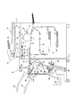
以下図示の本発明の好適な実施の態様に基づいて本発明を詳述する。図1は本発明に係わる画像形成装置Aとシート処理装置Bを備えた画像形成システムを示す全体構成図であり、図2はシート処理装置Bの詳細構成の説明図である。   The present invention will be described in detail below based on the preferred embodiments of the present invention shown in the drawings. FIG. 1 is an overall configuration diagram showing an image forming system including an image forming apparatus A and a sheet processing apparatus B according to the present invention, and FIG. 2 is an explanatory diagram of a detailed configuration of the sheet processing apparatus B.

[画像形成システムの構成]
図1に示す画像形成システムは画像形成装置Aとシート処理装置Bとから構成されている。そして画像形成装置Aの本体排出口3にシート処理装置Bの搬入口30が連結され、画像形成装置Aで画像形成されたシートをシート処理装置Bでステープル綴じして第1排紙トレイ24または第2排紙トレイ26に収納するように構成されている。また、第1排紙トレイ24の上方には綴じ処理を行わず直接シート収納するエスケープトレイ22が配設されている。
[Configuration of image forming system]
The image forming system shown in FIG. 1 includes an image forming apparatus A and a sheet processing apparatus B. Then, a carry-in port 30 of the sheet processing apparatus B is connected to the main body discharge port 3 of the image forming apparatus A, and the sheets formed with the image by the image forming apparatus A are stapled by the sheet processing apparatus B and the first discharge tray 24 or It is configured to be stored in the second paper discharge tray 26. Further, an escape tray 22 that directly stores sheets without performing binding processing is disposed above the first paper discharge tray 24.

[画像形成装置の構成]
画像形成装置Aについて図1に従って説明する。この画像形成装置Aは、給紙部1からシートを画像形成部2に送り、画像形成部2でシートに印刷した後、本体排出口3から排出するように構成されている。給紙部1は複数サイズのシートが給紙カセット1a、1bに収納してあり、指定されたシートを1枚ずつ分離して画像形成部2に給送する。
[Configuration of Image Forming Apparatus]
The image forming apparatus A will be described with reference to FIG. The image forming apparatus A is configured to send a sheet from the paper supply unit 1 to the image forming unit 2, print the sheet on the image forming unit 2, and then discharge the sheet from the main body discharge port 3. The sheet feeding unit 1 stores sheets of a plurality of sizes in sheet feeding cassettes 1 a and 1 b, and separates specified sheets one by one and feeds them to the image forming unit 2.

画像形成部2には例えば静電ドラム4と、その周囲に配置された印字ヘッド(レーザ発光器)5と現像器6と、転写チャージャ7と定着器8が配置されている。画像形成部2は、静電ドラム4上にレーザ発光器5で静電潜像を形成し、これに現像器6でトナーを付着し、転写チャージャ7でシート上に画像を転写し、定着器8で加熱定着し画像形成する。このようにして画像形成されたシートは本体排出口3から順次搬出される。図示9は循環経路であり、定着器8から表面側に印刷したシートを、スイッチバック経路10を介して表裏反転した後、再び画像形成部2に給送してシートの裏面側に印刷する両面印刷の経路である。このように両面印刷されたシートはスイッチバック経路10で表裏反転された後、本体排出口3から搬出される。 In the image forming unit 2, for example, an electrostatic drum 4, a print head (laser light emitter) 5, a developing device 6, a transfer charger 7, and a fixing device 8 are arranged around the electrostatic drum 4. The image forming unit 2 forms an electrostatic latent image on the electrostatic drum 4 by the laser light emitter 5, attaches toner to the developer drum 6, transfers the image onto the sheet by the transfer charger 7, and fixes the image on the sheet. In step 8, the image is formed by heating and fixing. The sheets on which images are formed in this way are sequentially carried out from the main body discharge port 3. 9 is a circulation path. A sheet printed on the front side from the fixing device 8 is reversed on the front and back via the switchback path 10 and then fed again to the image forming unit 2 to print on the back side of the sheet. This is the print path. The sheet printed on both sides in this way is turned upside down by the switchback path 10 and then carried out from the main body discharge port 3.

図示11は画像読取装置であり、プラテン12上にセットした原稿シートをスキャンユニット13で走査し、図示しない光電変換素子で電気的に読み取る。この画像データは画像処理部で例えばデジタル処理された後、データ記憶部14に転送され、前記レーザ発光器5に画像信号を送る。また、図示15は原稿送り装置であり、原稿スタッカ16に収容した原稿シートをプラテン12に給送する。   11 is an image reading apparatus, which scans a document sheet set on a platen 12 with a scanning unit 13 and electrically reads it with a photoelectric conversion element (not shown). The image data is digitally processed by an image processing unit, for example, and then transferred to the data storage unit 14 to send an image signal to the laser emitter 5. 15 is a document feeder, which feeds document sheets stored in the document stacker 16 to the platen 12.

上記構成の画像形成装置Aには図12に示す画像形成制御部200が設けられ、コントロールパネル18から入力部203を介して、画像形成条件、例えばシートサイズ指定、カラー・モノクロ印刷指定、プリント部数指定、片面・両面印刷指定、拡大・縮小印刷指定などの印刷条件が設定される。また、画像形成装置Aには上記スキャンユニット13で読み取った画像データ或いは外部のネットワークから転送された画像データがデータ貯蔵部17に蓄積される。このデータ貯蔵部17から画像データはバッファメモリ19に転送され、このバッファメモリ19から順次にレーザ発光器5にデータ信号が移送されるように構成されている。   The image forming apparatus A configured as described above is provided with an image forming control unit 200 shown in FIG. 12, and image forming conditions such as sheet size designation, color / monochrome printing designation, and number of copies to be printed from the control panel 18 via the input unit 203. Printing conditions such as designation, single-sided / double-sided printing designation, and enlargement / reduction printing designation are set. In the image forming apparatus A, image data read by the scan unit 13 or image data transferred from an external network is accumulated in the data storage unit 17. The image data is transferred from the data storage unit 17 to the buffer memory 19, and the data signal is transferred from the buffer memory 19 to the laser emitter 5 sequentially.

上記コントロールパネル18からは上述の片面/両面印刷、拡大/縮小印刷、モノクロ/カラー印刷などの画像形成条件と同時にシート処理条件も入力指定される。このシート処理条件は、例えば「プリントアウトモード」「端面綴じモード」「中綴じモード」等が設定される。なお、これらの処理条件については後述する。   From the control panel 18, sheet processing conditions are also input and specified simultaneously with the image forming conditions such as single-sided / double-sided printing, enlargement / reduction printing, and monochrome / color printing described above. As the sheet processing condition, for example, “print-out mode”, “end face binding mode”, “saddle stitching mode”, or the like is set. These processing conditions will be described later.

[シート処理装置Bの構成]
シート処理装置Bは図1及び図2に示す様に、装置フレーム20に一方に設けられたシートの搬入口30と、これと反対の外側に設けられた1枚シートや比較的厚いシートを集積するエスケープトレイ22が配置されている。このエスケープトレイ22の下方には、端面綴じ処理したシートや比較的量が多いシートを集積する昇降可能な排紙トレイとしての第1排紙トレイ24が位置している。さらにこの第1排紙トレイ24の下方には、中綴じあるいは折り処理されたシートを集積する第2排紙トレイ26が設けられている。なお、この発明で端面とは、シートの端部周辺の面、すなわちシート縁部の表裏面を示している。
[Configuration of Sheet Processing Apparatus B]
As shown in FIG. 1 and FIG. 2, the sheet processing apparatus B accumulates a sheet carry-in port 30 provided on one side of the apparatus frame 20 and a single sheet or a relatively thick sheet provided on the opposite side. An escape tray 22 is disposed. Below the escape tray 22 is positioned a first paper discharge tray 24 as a paper discharge tray that can be moved up and down to collect sheets that have undergone end-face stitching and a relatively large amount of sheets. Further, below the first paper discharge tray 24, there is provided a second paper discharge tray 26 for collecting the saddle stitched or folded sheets. In the present invention, the end surface indicates the surface around the end of the sheet, that is, the front and back surfaces of the sheet edge.

[シート搬送経路]
このシート処理装置Bの上記搬入口30からは搬入経路32から第1処理トレイ出口50まで略直線的に延びる搬送経路42が配置されている。搬入経路32にはパンチユニット31が設けられ、シートの端面や必要に応じて搬送方向の中程にパンチ処理する。このパンチユニット31の搬入経路32を挟んだ下方にはパンチ処理時に発生するパンチ屑を集積するパンチ屑ボックス31bが装置フレーム20に着脱自在に設けられている。
[Sheet transport path]
A conveyance path 42 extending substantially linearly from the carry-in path 32 to the first processing tray outlet 50 is disposed from the carry-in entrance 30 of the sheet processing apparatus B. A punch unit 31 is provided in the carry-in path 32, and performs punching in the middle of the sheet end face and, if necessary, in the transport direction. A punch waste box 31b for accumulating punch waste generated during the punching process is detachably provided in the apparatus frame 20 below the carry-in path 32 of the punch unit 31.

上記パンチユニット31の下流側にはシートを搬送する搬入ローラ34が配置されシートを高速で搬送する。この搬入ローラ34の下流側の搬送経路42には、シートを第1トレイである第1処理トレイ54やその下流側の第1排紙トレイ24に導く正逆転可能な搬送ローラ44が設けられている。この搬送ローラ44の後方はシートを搬送経路出口46となっている。   A carry-in roller 34 that conveys the sheet is disposed downstream of the punch unit 31 and conveys the sheet at high speed. A conveyance path 42 downstream of the carry-in roller 34 is provided with a conveyance roller 44 capable of rotating forward and backward to guide the sheet to the first processing tray 54 as a first tray and the first paper discharge tray 24 on the downstream side. Yes. Behind the conveyance roller 44 is a sheet conveyance path outlet 46.

この搬送経路出口46の下流側には、正逆転可能な出口ローラ48が設けられている。この出口ローラ48は、シートをスイッチバックして第1処理トレイ54にシートを搬送したり、第1排紙トレイ24にストレートで排出したり、あるいは第1処理トレイ54に集積されて端面綴じ処理されたシートの束を第1排紙トレイ24に排出する。 On the downstream side of the conveyance path outlet 46, an outlet roller 48 capable of forward and reverse rotation is provided. The exit roller 48 switches back the sheet and conveys the sheet to the first processing tray 54, discharges the sheet straight to the first discharge tray 24, or is stacked on the first processing tray 54 and end-face binding processing. The bundle of sheets thus discharged is discharged to the first discharge tray 24.

[エスケープ経路、分岐経路]
また、搬送経路42は、シートをエスケープトレイ22に案内するエスケープ経路38と、比較的長いシートを中綴じ処理や折り処理するために第2トレイとなるスタッカ84(第2処理トレイでもある)案内する分岐経路70に分岐位置36で分岐されている。この分岐位置36にはシートを搬送経路42にそのまま搬送するか、エスケープ経路38に搬送するか、搬送経路42上でスイッチバックさせて分岐経路70に案内するかを選択するための経路の切り替えゲート37が設けられている。
なお、エスケープ経路38には、シートを搬送するエスケープローラ39とエスケープトレイ22にシートを排出するエスケープ出口ローラ40が設けられている
[Escape route, branch route]
Further, the conveyance path 42 includes an escape path 38 for guiding sheets to the escape tray 22 and a stacker 84 (also a second processing tray) serving as a second tray for performing saddle stitching processing and folding processing of relatively long sheets. The branch path 70 is branched at the branch position 36. At this branch position 36, a path switching gate for selecting whether the sheet is transported to the transport path 42 as it is, transported to the escape path 38, or switched back on the transport path 42 and guided to the branch path 70. 37 is provided.
The escape path 38 is provided with an escape roller 39 for conveying the sheet and an escape outlet roller 40 for discharging the sheet to the escape tray 22.

[端面綴じ部60]
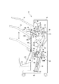
ところで、搬送経路42の搬送経路出口46の下方には第1トレイとしての第1処理トレイ54が設けられその下端側には、この第1処理トレイ54上に一時集積したシートの端面を綴じる端面綴じ部60が位置している。この端面綴じ部60については、追って図3により説明する。
[中綴じ部80]
一方、比較的長いシートを上記の搬送経路42を第1処理トレイ54方向に一旦搬送し、切り替えゲート37の下流側に搬送後、今度はスイッチバック搬送して分岐経路70に搬送して分岐出口76から第2トレイとしてのスタッカ84(第2処理トレイ)に集積する。図2に示す様に分岐出口76には、分岐出口ローラ74からスタッカ84にシートが搬入される毎にシートを図示左側に付勢して先行シート後端と次シート先端の衝突を防止する変更フラッパ78が設けられている。上記のスタッカ84にはシートの搬送方向の中程を綴じる中綴じ部80が位置している。
[End face binding portion 60]
By the way, a first processing tray 54 as a first tray is provided below the conveyance path outlet 46 of the conveyance path 42, and an end surface for binding an end surface of the sheets temporarily accumulated on the first processing tray 54 at the lower end side thereof. The binding part 60 is located. The end face binding portion 60 will be described later with reference to FIG.
[Saddle Stitcher 80]
On the other hand, a relatively long sheet is once transported along the transport path 42 toward the first processing tray 54 and transported to the downstream side of the switching gate 37, and then switched back and transported to the branch path 70 for branch exit. The stacker 76 accumulates in a stacker 84 (second processing tray) as a second tray. As shown in FIG. 2, at the branch outlet 76, every time a sheet is loaded from the branch outlet roller 74 to the stacker 84, the sheet is urged to the left side in the drawing to prevent collision between the trailing edge of the preceding sheet and the leading edge of the next sheet. A flapper 78 is provided. The stacker 84 is provided with a saddle stitching portion 80 for binding the middle in the sheet conveyance direction.

[スタッカ(第2トレイ/第2処理トレイ)と周辺]
スタッカ84にはシートの搬入位置を規定するストッパ85が位置している。このストッパ85は、スタッカ84の側方で上プーリ86と下プーリ87に張設された移動ベルトをストッパ移動モータ85Mで駆動することにより図示矢印方向に移動する。ストッパ85の位置は、シートがスタッカ84に搬入の際にシートの後端が上記の変更フラッパ78で変更できる位置、シートの搬送方向の略中央を中綴じユニット82で中綴じを行う位置、及び中綴じされた位置を折りローラ92対に往復動する折りブレード94で押し込んでシートの束を二つ折りする位置に夫々停止する。
また、折りローラ92の上下には、シートのスタッカ84の搬入の都度シート幅方向からシートの両側縁を押圧して揃え動作を行う中綴じ整合板81が設けられている。
[Stacker (second tray / second processing tray) and surrounding area]
The stacker 84 is provided with a stopper 85 that defines a sheet carry-in position. The stopper 85 moves in the direction of the arrow shown in the figure by driving a moving belt stretched around the upper pulley 86 and the lower pulley 87 by a stopper moving motor 85M on the side of the stacker 84. The position of the stopper 85 includes a position where the trailing edge of the sheet can be changed by the change flapper 78 when the sheet is carried into the stacker 84, a position where the saddle stitching unit 82 performs saddle stitching at a substantially center in the sheet conveyance direction, and The saddle-stitched position is pushed by a folding blade 94 that reciprocates to the pair of folding rollers 92 and stopped at a position where the sheet bundle is folded in half.
In addition, a saddle stitch aligning plate 81 is provided above and below the folding roller 92 to perform an aligning operation by pressing both side edges of the sheet from the sheet width direction every time the sheet stacker 84 is loaded.

[中綴じユニット82]
中綴じ部80には、シートの束を、例えばステープル針を中綴じユニット82内のドライバによって打ち込み、これに対向する位置に設けられステープル針の脚部を折り曲げるアンビル83が設けられている。この中綴じユニット82は既に広く知られているので、ここでの説明を省略するが、綴じ手段としてはステープル針をシート束に貫通して綴じるのみではなく、シートの搬送方向中央に接着剤を塗布して、シートを貼り合せて束とする機構であってもよい。
[Saddle stitching unit 82]
The saddle stitching portion 80 is provided with an anvil 83 which is provided at a position opposite to a staple of a bundle of sheets, for example, driven by a driver in the saddle stitching unit 82 and bends a leg portion of the staple needle. Since the saddle stitching unit 82 is already widely known, a description thereof will be omitted. However, as a binding means, not only the staple needle is passed through the sheet bundle, but also an adhesive is provided at the center in the sheet conveying direction. It may be a mechanism that coats and pastes the sheets into a bundle.

[第2排紙トレイ26周辺]
上記の中綴じユニット82で綴じられたシート束は、折りローラ92とこれにシート束を押し込む折りブレード94によって、二つ折りにされながらのこの折りローラ92とその下流側に位置する束排出ローラ96によって、第2排紙トレイ26に排出される。この第2排紙トレイ26には、折り処理されその背側を先端側として排出される折りシート束を第2排紙トレイ26に落下させる先端に回転自在のコロを設け揺動自在の押えローラ102と、集積した折りシート束が広がらないように上から押える押えレバー104が取り付けられている。この押えローラ102と押えレバー104により折りシート束が開いてしまい集積性の低下を低減している。
[Around the second paper output tray 26]
The sheet bundle bound by the
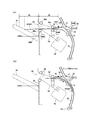
 saddle stitching unit 82 is folded in half by a folding roller 92 and a folding blade 94 that pushes the sheet bundle into the folding roller 92 and a bundle discharge roller 96 positioned downstream thereof. As a result, the sheet is discharged to the second discharge tray 26. The second discharge tray 26 is provided with a rotatable roller at the front end for dropping a folded sheet bundle that is folded and discharged with the back side as the front end side to the second discharge tray 26, and is a swingable press roller. 102, and a presser lever 104 that is pressed from above so that the bundle of folded folded sheets does not spread. The folded sheet bundle is opened by the presser roller 102 and the presser lever 104, and the deterioration of the accumulation property is reduced.

[分岐位置36、端面綴じ部60の詳細]
ここで、図3により分岐位置36や端面綴じ部60について、さらに説明を付加する。既に説明したようにここでは、搬入口30から搬入ローラ34が配置された搬入経路32、これから第1処理トレイ54方向に直線的に延びる搬送経路42、この搬送経路42から図示上方に延びるエスケープ経路38と下方に湾曲して伸びるシートをスタッカ84に案内する分岐経路70が示されている。分岐位置36には搬入経路32のシートをエスケープ経路38か搬送経路42経路か、または搬送経路42をスイッチバック搬送してくるシートを分岐経路70に選択的に位置して案内する変更フラッパ78が配置されている。
[Details of branch position 36 and end face binding portion 60]
Here, the branch position 36 and the end surface binding portion 60 will be further described with reference to FIG. As described above, here, the carry-in path 32 in which the carry-in roller 34 is arranged from the carry-in entrance 30, the conveyance path 42 extending linearly from the conveyance path 42 toward the first processing tray 54, and the escape path extending from the conveyance path 42 upward in the figure. 38 and a branch path 70 for guiding a sheet extending downward and curved to the stacker 84 is shown. At the branch position 36, there is a change flapper 78 for selectively guiding the sheet on the carry-in path 32 to the escape path 38, the transport path 42, or the switch path transporting the transport path 42 in the branch path 70. Has been placed.

この実施の形態にあっては、例えば図3に示すように、実線位置でエスケープ経路38を塞いで、シートを搬入経路32から搬送経路42に案内するようになっており、破線位置では搬入経路32から搬送されるシートはエスケープ経路38へ、搬送経路42をスイッチバック搬送されるシートは分岐経路70に案内することを示している。 In this embodiment, for example, as shown in FIG. 3, the escape path 38 is closed at the solid line position, and the sheet is guided from the carry-in path 32 to the transport path 42. It is shown that the sheet conveyed from 32 is guided to the escape path 38, and the sheet that is switched back along the conveyance path 42 is guided to the branch path 70.

上述した搬送経路42には、最終端である搬送経路出口46直前には、正逆転するとともに相互に離接する搬送ローラ44が配置される。すなわち、この搬送ローラ44が圧接状態での一方向回転で第1処理トレイ54側にシートを搬送し、他方回転で反対方向にスイッチバック搬送可能になっている。   In the transport path 42 described above, a transport roller 44 that rotates in the forward and reverse directions and is in contact with and away from each other is disposed immediately before the transport path exit 46 that is the final end. That is, the conveyance roller 44 can convey the sheet to the first processing tray 54 side by one-way rotation with the pressure contact state, and switchback conveyance in the opposite direction by the other rotation.

[スイッチバック搬送]
このスイッチバック搬送は、搬送経路42の切り替えゲート37の直後に配置されたシートセンサ42Sがシート後端の通過を検出した後、搬送ローラ44を他方回転させることよっておこなわれる。この他方回転のときは、切り替えゲート37が搬入経路32を塞ぐ位置(図3破線位置)に移動しており、これによりシートは分岐経路70に搬送され、分岐ローラ72によって引き継ぎ搬送される、シート後端が所定位置到達するとこの分岐ローラ72を停止して、分岐経路70でシートを待機状態とする。
[Switchback transport]
This switchback conveyance is performed by rotating the conveyance roller 44 in the other direction after the sheet sensor 42S disposed immediately after the switching gate 37 of the conveyance path 42 detects the passage of the trailing edge of the sheet. At the time of the other rotation, the switching gate 37 is moved to a position (broken line position in FIG. 3) that closes the carry-in path 32, whereby the sheet is conveyed to the branch path 70 and taken over by the branch roller 72. When the trailing end reaches a predetermined position, the branch roller 72 is stopped, and the sheet is placed in a standby state on the branch path 70.

ところで、搬送ローラ44の下流側であり第1処理トレイ出口50(第1処理トレイ54の出口)には、正逆転するとともに相互に離接する出口ローラ48が配置されている。この出口ローラ48は、出口上ローラ48aと出口下ローラ48bとからなり、これらが相互に圧接状態での一方向回転で、上記の搬送ローラ44と協働して第1排紙トレイ24にシートを搬送し、他方回転で分岐経路70にシートを搬送する。また、出口ローラ48は、第1処理トレイ54に集積して束としたシートを第1排紙トレイ24に後述する基準面57の移動と協働して排出する際も使用される。   By the way, on the downstream side of the transport roller 44 and at the first processing tray outlet 50 (the outlet of the first processing tray 54), there are disposed outlet rollers 48 that are forwardly and reversely rotated and separated from each other. The exit roller 48 includes an exit upper roller 48 a and an exit lower roller 48 b, which rotate in one direction while being pressed against each other, and cooperate with the transport roller 44 to form a sheet on the first discharge tray 24. The sheet is conveyed to the branch path 70 by the other rotation. Further, the exit roller 48 is also used when the sheets stacked on the first processing tray 54 to be bundled are discharged to the first paper discharge tray 24 in cooperation with the movement of a reference surface 57 described later.

[第1処理トレイ54への集積]
ここで、第1処理トレイ54へのシートの集積について説明する。この第1処理トレイ54への集積は、搬送ローラ44から放出したシートを下流側に位置する出口ローラ48の他方回転で第1処理トレイ54の傾斜面を図3右側に搬送する。この搬送されたシートを突起付ベルト146が巻回されたかき込みコロ56を図示反時計方向に回転して移送する。この移送によりシートの搬送方向先端は他面の綴じ基準となる基準面57に当接して停止する。このとき上記かき込みコロ56はシート上を滑り、シート先端が基準面に当接後に座屈することを防いでいる。
[Accumulation on the first processing tray 54]
Here, the accumulation of sheets on the first processing tray 54 will be described. In the accumulation on the first processing tray 54, the sheet discharged from the conveying roller 44 is conveyed to the right side in FIG. 3 by the other rotation of the outlet roller 48 positioned on the downstream side. The transported sheet 56 is transported by rotating the scraping roller 56 around which the belt 146 with protrusions is wound counterclockwise. By this transfer, the front end of the sheet in the conveyance direction comes into contact with the reference surface 57 serving as a binding reference for the other surface and stops. At this time, the scraping roller 56 slides on the sheet and prevents the sheet tip from buckling after contacting the reference surface.

[端面綴じユニット62の移動と綴じ処理]
シートが搬送ローラ44から放出されることに出口ローラ48とかき込みコロの回転によりシートを基準面57に送り第1処理トレイ54上に積み重ねていく。また、この積み重ね動作に合わせて、整合板58をシート幅方向の両側から当接させてシートを第1処理トレイ54の幅方向中央に整合する。このような積み重ねと整合を束とする指定の枚数になるまで繰り返す。指定枚数になると、今度は移動台63の上をシートの端面をシート幅方向に移動する端面綴じユニット62を所望の綴じ位置に移動する。この移動は、移動台63にシート幅方向に設けられた図示の溝レールに端面綴じユニット62の移動ピン62bが勘合して案内されてなされる。
[Movement and binding processing of end face binding unit 62]
When the sheet is discharged from the conveying roller 44, the sheet is sent to the reference surface 57 and stacked on the first processing tray 54 by the rotation of the exit roller 48 and the scooping roller. In accordance with this stacking operation, the aligning plate 58 is brought into contact with both sides in the sheet width direction to align the sheet with the center in the width direction of the first processing tray 54. This process is repeated until the designated number of stacks and alignments are bundled. When the designated number is reached, the end face binding unit 62 that moves the end face of the sheet in the sheet width direction on the moving table 63 is moved to a desired binding position. This movement is made by guiding the moving pin 62b of the end face binding unit 62 into the illustrated groove rail provided on the moving base 63 in the sheet width direction.

端面綴じユニット62の綴じ処理は既に公知なので説明を省略するが、端面綴じユニット62が指定した綴じ位置で停止すると、端面綴じモータ62Mが回転駆動して、図示していないドライバを移動してステープル針をシートの束に打ち込み、打ち込まれたステープル針をアンビルによって折り曲げて綴じ処理する。この綴じ処理はシートの角の端面や幅方向の端面の複数位置に行う。 Since the binding processing of the end surface binding unit 62 is already known, the description thereof will be omitted. However, when the end surface binding unit 62 stops at the specified binding position, the end surface binding motor 62M is driven to rotate, and a driver (not shown) is moved to move the staple. The staples are driven into a bundle of sheets, and the staple needles that have been driven are folded by an anvil and bound. This binding process is performed at a plurality of positions on the end face of the sheet corner and the end face in the width direction.

[端面綴じシートの排出]
端面綴じユニット62で綴じ処理されたシート束は、第1処理トレイ54下の右プーリ65と左プーリ66に架け渡された基準面移動ベルト64の図示反時計方向の移動により、この基準面移動ベルト64に連結された基準面57が図示左方向に移動することにより、シート束の綴じ端面側を第1排紙トレイ24に向けて押し出す。この押し出しとともに第1処理トレイ54の出口に配置された出口ローラ48で綴じられたシート束を表裏から押圧し、時計方向の回転により第1排紙トレイ24に綴じられたシート束を排出する。
[Ejecting edge-bound sheets]
The sheet bundle that has been subjected to the binding process by the end surface binding unit 62 is moved by the reference plane moving belt 64 in the counterclockwise direction of the reference plane moving belt 64 spanned between the right pulley 65 and the left pulley 66 below the first processing tray 54. The reference surface 57 connected to the belt 64 moves in the left direction in the figure, thereby pushing out the binding end surface side of the sheet bundle toward the first paper discharge tray 24. Along with this extrusion, the sheet bundle bound by the outlet roller 48 disposed at the outlet of the first processing tray 54 is pressed from the front and back, and the sheet bundle bound to the first paper discharge tray 24 is discharged by the clockwise rotation.

[第1排紙トレイ24の昇降]
シート束を集積する第1排紙トレイ24について説明する。図3に示す様にこの第1排紙トレイ24は第1処理トレイ54と傾斜角度を略同様にして配置され、第1処理トレイ54から排出される綴じシート束や搬送経路42から搬送ローラ44、出口ローラ48によって排出される1枚毎のシートも集積する。
この第1排紙トレイ24の底面側には、第1排紙トレイ24を昇降する昇降モータ24Mが設けられ、この駆動は昇降ピニオン109に伝達される。昇降ピニオン109は、装置フレーム20の立ち面28の両側に上下に固定して設けられた昇降ラック107に係合している。また、特に図示していないが、第1排紙トレイ24の立ち面28に設けられた昇降レールで上下を案内している。
[Raising and lowering the first discharge tray 24]
The first paper discharge tray 24 for collecting the sheet bundle will be described. As shown in FIG. 3, the first paper discharge tray 24 is disposed at substantially the same inclination angle as the first processing tray 54, and the binding sheet bundle discharged from the first processing tray 54 and the transport roller 42 through the transport path 42. The sheets discharged by the exit roller 48 are also collected.
On the bottom surface side of the first paper discharge tray 24, a lift motor 24M that lifts and lowers the first paper discharge tray 24 is provided, and this drive is transmitted to the lift pinion 109. The elevating pinion 109 is engaged with an elevating rack 107 that is fixed up and down on both sides of the standing surface 28 of the apparatus frame 20. Although not specifically shown, the elevator rail is guided up and down by an elevating rail provided on the standing surface 28 of the first paper discharge tray 24.

なお、図3に示してあるように、第1処理トレイ54下方から第1排紙トレイ24上面に延長して、第1処理トレイ54から搬送されるシートの下面をガイドする補助ガイド110が設けられている。この補助ガイド110の構成等については、図6を用いて後述する。 As shown in FIG. 3, an auxiliary guide 110 is provided that extends from below the first processing tray 54 to the upper surface of the first paper discharge tray 24 and guides the lower surface of the sheet conveyed from the first processing tray 54. It has been. The configuration of the auxiliary guide 110 will be described later with reference to FIG.

ところで、第1排紙トレイ24の位置またはこの第1排紙トレイ24に集積されたシートの位置は、立ち面側に設けた紙面センサ24Sによって検出する。そして、この紙面センサ24Sが検出すると昇降モータ24Mを駆動して、昇降ピニオン109を回転して下降するようになっている。図3の状態は、第1排紙トレイ24の上面を紙面センサ24Sで検出している状態で、ここから多少下降してシート束を受け入れることになる。従って、第1処理トレイ54からの出口位置の上面と、第1排紙トレイ24の上面は段差を持って位置している。 Incidentally, the position of the first paper discharge tray 24 or the position of the sheets stacked on the first paper discharge tray 24 is detected by a paper surface sensor 24S provided on the standing surface side. And when this paper surface sensor 24S detects, the raising / lowering motor 24M will be driven and the raising / lowering pinion 109 will rotate and it will descend | fall. In the state of FIG. 3, the upper surface of the first paper discharge tray 24 is detected by the paper surface sensor 24S, and the sheet bundle is lowered slightly from here to accept the sheet bundle. Accordingly, the upper surface of the exit position from the first processing tray 54 and the upper surface of the first paper discharge tray 24 are positioned with a step.

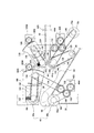
次に、図4により搬送ローラ44と出口ローラ48の回転駆動及び離接の構成について説明する。
[搬送上ローラ44aの回転駆動]
まず搬送上ローラ44aと搬送下ローラ44bからなる搬送ローラ44の駆動は、搬送ローラモータ44Mで行われる。この搬送ローラモータ44Mはハイブリッド型のステッピングモータから構成され、モータ軸の回転速度を検出する速度検出センサ44Sが配置されている。この搬送ローラモータ44Mの駆動は、伝達ギア120、122、伝達ベルト124を介してアームギア126に伝達される。このアームギア126から駆動は、搬送ローラ支持アーム136に支持された搬送上ローラ44aの上ローラ軸44ujに伝達ベルト128で伝達される。
Next, the configuration of rotational driving and separation / contact of the conveying roller 44 and the outlet roller 48 will be described with reference to FIG.
[Rotation drive of transport upper roller 44a]
First, driving of the transport roller 44 including the transport upper roller 44a and the transport lower roller 44b is performed by a transport roller motor 44M. The transport roller motor 44M is composed of a hybrid type stepping motor, and a speed detection sensor 44S for detecting the rotational speed of the motor shaft is disposed. The driving of the conveying roller motor 44M is transmitted to the arm gear 126 via the transmission gears 120 and 122 and the transmission belt 124. The drive from the arm gear 126 is transmitted by the transmission belt 128 to the upper roller shaft 44 uj of the transport upper roller 44 a supported by the transport roller support arm 136.

[搬送上ローラ44aの離接]
また、搬送上ローラ44aは固定された搬送下ローラ44bに対して離接するためアームギア126の軸を中心に回動されるように取り付けられている。この離接は、アームギア126の軸に取り付けられた後方扇形ギアを有し、先端側の移動アーム先に搬送上ローラ44aを付勢するバネ134が取り付けられた搬送ローラ移動アーム130によって行われる。すなわち、上記の後方扇形ギアに係合する搬送ローラ移動アームモータ130Mを正逆転駆動することにより、一方向回転により矢印Oの解放方向に、他方回転により矢印Cの搬送下ローラ44bに圧接する矢印Cの圧接方向に移動する。なお、搬送ローラ移動アームモータ130Mもステッピングモータで構成されるとともに、搬送ローラ移動アーム130の位置を搬送ローラ移動アームセンサ130Sで検出するようになっている。
[Separation of transport upper roller 44a]
Further, the transport upper roller 44a is attached so as to be rotated about the axis of the arm gear 126 so as to be separated from and in contact with the fixed transport lower roller 44b. This separation / contact is performed by a conveyance roller moving arm 130 having a rear sector gear attached to the shaft of the arm gear 126 and having a spring 134 attached to the tip of the movement arm on the front end side for urging the conveyance upper roller 44a. That is, by driving the transport roller moving arm motor 130M engaged with the rear fan gear forward and backward, the arrow that presses the transport lower roller 44b indicated by the arrow C in the release direction of the arrow O by one rotation and the arrow C by the other rotation. Move in the direction of pressure contact of C. The transport roller moving arm motor 130M is also constituted by a stepping motor, and the position of the transport roller moving arm 130 is detected by the transport roller moving arm sensor 130S.

[搬送下ローラ44bなどの回転駆動]
搬送下ローラ44bの回転駆動は、搬送ローラモータ44Mの駆動を、伝達ギア120、伝達ベルト138を介して搬送下ローラ軸44sjに個設された受けギア142伝達して行われる。
また、この受けギア142からの駆動は、ワンウェイクラッチ付ギア144、伝達ベルトの役割もする突起付ベルト146をかき込みコロ56を回転する。このかき込みコロ56は、ワンウェイクラッチ付ギア144を介して伝達されているので、既に説明したように受けギア142が正逆回転しても図4の実線矢印方向のみにしか回転せず、第1処理トレイ54の基準面57の方向のみに移送する。
また、搬送ローラモータ44Mの駆動は、伝達ギア120、伝達ベルト148を介して、分岐経路70中でシートを搬送する分岐ローラ72の分岐下ローラ72bの分岐下ローラ軸72sjにも伝達される。
[Rotation drive of lower conveying roller 44b, etc.]
The rotation of the lower conveying roller 44b is performed by transmitting the driving of the conveying roller motor 44M via the transmission gear 120 and the transmission belt 138 to the receiving gear 142 provided on the lower conveying roller shaft 44sj.
Further, the driving from the receiving gear 142 rotates the roller 56 by driving the gear 144 with a one-way clutch and the belt 146 with a projection that also functions as a transmission belt. Since the scraping roller 56 is transmitted via the one-way clutch-equipped gear 144, as described above, even if the receiving gear 142 rotates forward and backward, it rotates only in the direction indicated by the solid line in FIG. It is transferred only in the direction of the reference surface 57 of the processing tray 54.
The driving of the conveyance roller motor 44M is also transmitted to the lower branch roller shaft 72sj of the lower branch roller 72b of the branch roller 72 that conveys the sheet in the branch path 70 via the transmission gear 120 and the transmission belt 148.

[搬送ローラモータ44Mの速度設定]
以上の構成により、搬送ローラモータ44Mの正逆回転に従い、搬送ローラ44、分岐ローラ72は図示実線矢印方向の一方向と破線矢印方向の他方向(スイッチバック方向)に、かき込みローラは実線矢印方向の基準面57方向に回転する。また、この搬送ローラモータ44Mは、シートを第1処理トレイ54側に搬送する際には約1100mm/sで、分岐経路70側へのスイッチバック搬送の際は約1100mm/sまたはこれより低速の約600mm/sの速度でシート搬送ができるよう任意に設定可能となっている。この速度は起動から回転設定速度であり、平均速度はこの設定値より低くなるが、何れにしてもシートの搬送方向やシート長さあるいは待機搬送か第2トレイ搬送かの搬送モード等で搬送速度が可変となるようになっている。この速度設定については後述する。
[Speed setting of transport roller motor 44M]
With the above configuration, according to the forward / reverse rotation of the transport roller motor 44M, the transport roller 44 and the branching roller 72 are in one direction indicated by the solid line arrow in the figure and the other direction (switchback direction) in the direction indicated by the broken line arrow, Rotate in the direction of the reference plane 57. Further, the transport roller motor 44M is about 1100 mm / s when transporting the sheet to the first processing tray 54 side, and about 1100 mm / s or lower when performing switchback transport to the branch path 70 side. It can be arbitrarily set so that the sheet can be conveyed at a speed of about 600 mm / s. This speed is the rotation set speed from the start, and the average speed is lower than this set value, but in any case, the transport speed in the transport direction of the sheet, the sheet length, the transport mode of standby transport or second tray transport, etc. Is designed to be variable. This speed setting will be described later.

[出口上ローラ48aの回転駆動]
出口上ローラ48aと出口下ローラ48bからなる出口ローラ48の駆動は、出口ローラモータ48Mで行われる。この出口ローラモータ48Mもハイブリッド型のステッピングモータから構成され、モータ軸の回転速度を検出する速度検出センサ48Sも同様に配置されている。この出口ローラモータ48Mの駆動は、伝達ギア150、152、伝達ベルト154を介して出口アームギア156に伝達される。出口アームギア156から駆動は、出口ローラ支持アーム166に支持された出口上ローラ48aの出口上ローラ軸に伝達ベルト158で伝達される。
[Rotation drive of outlet upper roller 48a]
The exit roller 48 comprising the exit upper roller 48a and the exit lower roller 48b is driven by the exit roller motor 48M. The exit roller motor 48M is also composed of a hybrid stepping motor, and a speed detection sensor 48S for detecting the rotational speed of the motor shaft is similarly arranged. The drive of the exit roller motor 48M is transmitted to the exit arm gear 156 via the transmission gears 150 and 152 and the transmission belt 154. Drive from the exit arm gear 156 is transmitted by the transmission belt 158 to the exit upper roller shaft of the exit upper roller 48a supported by the exit roller support arm 166.

[出口上ローラ48aの離接など]
出口上ローラ48aは固定された出口下ローラ48bに対して離接するため出口アームギア156の軸を中心に回動されるように取り付けられている。この離接は、出口アームギア156の軸に取り付けられた後方扇形ギアを有し、先端側の移動アーム先に出口上ローラ48aを付勢するバネ164が取り付けられた出口ローラ移動アーム160によって行われる。上記の後方扇形ギアに係合する出口ローラ移動アームモータ160Mを正逆転駆動することにより、一方向回転により矢印Oの解放方向に、他方回転により矢印Cの出口下ローラ48bに圧接する矢印Cの圧接方向に移動する。なお、出口ローラ移動アームモータ160Mもステッピングモータで構成されるとともに、出口ローラ移動アーム160の位置を出口ローラ移動アームセンサ160Sで検出するようになっている。
また、出口下ローラ48bの回転駆動は、出口ローラモータ48Mの駆動を、伝達ギア150、伝達ベルト168を介して出口下ローラ軸48sjに個設された受けギア169に伝達して行われる。
[Separation of roller 48a on exit, etc.]
The outlet upper roller 48a is attached so as to be rotated around the axis of the outlet arm gear 156 so as to be in contact with and away from the fixed lower outlet roller 48b. This separation / contact is performed by an exit roller moving arm 160 having a rear sector gear attached to the shaft of the exit arm gear 156 and having a spring 164 for biasing the exit upper roller 48a attached to the distal end side of the moving arm. . By driving the outlet roller moving arm motor 160M engaged with the rear fan gear in the forward and reverse directions, the release direction of the arrow O is rotated in one direction, and the arrow C is pressed against the outlet lower roller 48b in the arrow C by the other rotation. Move in the pressure direction. The exit roller moving arm motor 160M is also constituted by a stepping motor, and the position of the exit roller moving arm 160 is detected by the exit roller moving arm sensor 160S.
Further, the rotation of the outlet lower roller 48b is performed by transmitting the driving of the outlet roller motor 48M to the receiving gear 169 provided on the outlet lower roller shaft 48sj via the transmission gear 150 and the transmission belt 168.

[出口ローラモータ48Mの速度設定]
以上の構成により、出口ローラモータ48Mの正逆回転に従い、出口ローラ48は図示実線矢印方向の一方向と破線矢印方向の他方向(シートが搬送ローラ44から放出されてから第1処理トレイ54上で基準面57へのスイッチバック方向)に回転する。また、この出口ローラモータ48Mは、搬送ローラ44から引き継ぎ搬送する場合は約1100mm/sで、引き継ぎ基準面方向へのスイッチバック搬送の場合は約600mm/sで、第1処理トレイ54のシート束を基準面57の移動と協働して第1排紙トレイ24に排出する場合は約300mm/sの速度でシート搬送ができるよう設定可能となっている。すなわちこの出口ローラモータ48Mは約1100mm/sから約300mm/sの範囲での速度設定が可能としている。
なお、この実施の態様においては、待機搬送する場合のスイッチバック搬送時など搬送ローラ44でシート搬送を行っている場合は、駆動モータが分かれていて連動が難しいので、この出口上ローラ48aは出口下ローラ48bから解放された離間位置に位置している。
[Speed setting of outlet roller motor 48M]
With the above configuration, the outlet roller 48 moves in one direction in the direction indicated by the solid line arrow and in the other direction in the direction indicated by the broken line arrow (on the first processing tray 54 after the sheet is discharged from the conveying roller 44). In the switchback direction to the reference plane 57). The exit roller motor 48M is approximately 1100 mm / s when handed over from the transport roller 44, and is approximately 600 mm / s when switched back toward the takeover reference surface. Is discharged to the first paper discharge tray 24 in cooperation with the movement of the reference surface 57, it can be set so that the sheet can be conveyed at a speed of about 300 mm / s. That is, the outlet roller motor 48M can set a speed in the range of about 1100 mm / s to about 300 mm / s.
In this embodiment, when the sheet is being conveyed by the conveyance roller 44 such as during switchback conveyance during standby conveyance, the drive motor is separated and interlocking is difficult. It is located at a separated position released from the lower roller 48b.

[第1排紙トレイ24の紙面センサ24S]
既に、第1排紙トレイ24の昇降の機構は、図3で説明したが、図5により昇降位置の設定について述べる。昇降位置の設定は、紙面センサ24Sの紙面または第1排紙トレイ24上面の検出よって行われるが、この紙面センサ24Sは一端が回動自在に軸支されたセンサフラグ24fを検出することによって行われる。また、第1排紙トレイ24載置面には、シートが載置しているか否かを検出するエンプティセンサ25が設けられている。したがって、このエンプティセンサ25がONしている場合は、紙面センサ24Sはシート上面を検出していることになり、OFFの場合は、シートが載置されていない載置面の高さを検出していることになる。
[Paper surface sensor 24S of first discharge tray 24]
The mechanism for raising and lowering the first discharge tray 24 has already been described with reference to FIG. 3, but the setting of the raising and lowering position will be described with reference to FIG. The raising / lowering position is set by detecting the paper surface of the paper surface sensor 24S or the upper surface of the first paper discharge tray 24. This paper surface sensor 24S is set by detecting a sensor flag 24f pivotally supported at one end. Is called. Further, an empty sensor 25 for detecting whether or not a sheet is placed is provided on the surface on which the first paper discharge tray 24 is placed. Accordingly, when the empty sensor 25 is ON, the paper surface sensor 24S detects the upper surface of the sheet, and when OFF, the height of the mounting surface on which the sheet is not mounted is detected. Will be.

[第1排紙トレイ24の昇降位置設定]
ところで、第1排紙トレイ24の昇降位置は、第1処理トレイ54からシート束が排出されるときは、図5示されたL1+L2距離の24sh位置に載置面あるいは紙面が位置するように設定してある。また、シートが1枚ずつ排紙される場合には、シートの落下範囲を短くするL1距離の24Sh位置に載置面あるいは紙面が位置するように上昇設定する。また、搬送ローラ44でスイッチバク搬送するシートが短い場合や端面綴じのため分岐経路70に待機させるためのスイッチバック搬送である場合には、スイッチバックするシートの先端が第1排紙トレイ24に載置しているシートや載置台に触れないようにL1+L2+L3距離の24SL位置に下降設定する。
さらに、搬送ローラ44でスイッチバック搬送するシートが長い場合や中綴じのため分岐経路に搬送するためのスイッチバック搬送である場合には、スイッチバック搬送するシート先端の曲がりやバタつきを抑えるようにシートを案内するため段差範囲を短くするL1距離の24Sh位置に載置面あるいは紙面を近付ける上昇設定も行う。
[Raising / lowering position setting of first discharge tray 24]
Meanwhile, when the sheet bundle is discharged from the first processing tray 54, the raising / lowering position of the first discharge tray 24 is set so that the placement surface or the paper surface is positioned at the 24sh position of the L1 + L2 distance shown in FIG. It is. Further, when the sheets are discharged one by one, the setting is set so that the placement surface or the paper surface is positioned at the 24Sh position of the L1 distance that shortens the fall range of the sheet. In addition, when the sheet to be switched back by the transport roller 44 is short, or when the switchback transport is to make the branch path 70 wait for end-face binding, the leading edge of the sheet to be switched back to the first discharge tray 24. The position is lowered to the 24SL position of L1 + L2 + L3 distance so as not to touch the placed sheet or the placing table.
Further, when the sheet to be switched back by the transport roller 44 is long or when the switchback transport is performed to transport to the branch path for saddle stitching, the bending and fluttering of the leading edge of the sheet to be switched back are suppressed. In order to guide the sheet, an ascending setting is also made to bring the placement surface or the paper surface closer to the 24 Sh position of the L1 distance that shortens the step range.

[補助ガイド110について]
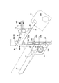
ここで、図3において多少触れたが、図6により第1処理トレイ54の下方の収納位置から第1排紙トレイ24の上方の案内位置に延設して、第1処理トレイ54から搬出されるシート下面を案内する補助ガイドについて説明する。 図6(a)は、図3における補助ガイド110の機構を示し、図6(b)は、補助ガイド110の部分拡大斜視図である。
図6(a)及び図6(b)に示す様に、補助ガイド110は、第1処理トレイ54下方の収納位置から第1排紙トレイ24またはこの第1排紙トレイ24に載置されたシート上方の案内位置に進出可能になっている。この補助ガイド110は、第1処理トレイ出口50の幅方向に配置された出口下ローラ48bに隣接して配置されている。本実施例にあっては、幅方向に2本の補助ガイド110が配置され、この補助ガイド110はその側部側部115が支持レール111に摺動可能に支持されている。また、補助ガイド110は図示の様になだらかな湾曲形状のレバーからなり、その裏面側にはガイドラック112がその移動方向全域に形成されている。
[About the auxiliary guide 110]
Here, although somewhat touched in FIG. 3, it extends from the storage position below the first processing tray 54 to the guide position above the first paper discharge tray 24 and is carried out of the first processing tray 54 according to FIG. An auxiliary guide for guiding the lower surface of the sheet will be described. 6A shows the mechanism of the auxiliary guide 110 in FIG. 3, and FIG. 6B is a partially enlarged perspective view of the auxiliary guide 110.
As shown in FIGS. 6A and 6B, the auxiliary guide 110 is placed on the first paper discharge tray 24 or the first paper discharge tray 24 from the storage position below the first processing tray 54. It is possible to advance to the guide position above the seat. The auxiliary guide 110 is disposed adjacent to the outlet lower roller 48 b disposed in the width direction of the first processing tray outlet 50. In this embodiment, two auxiliary guides 110 are arranged in the width direction, and the side portions 115 of the auxiliary guides 110 are slidably supported by the support rails 111. Further, the auxiliary guide 110 is formed of a gently curved lever as shown in the figure, and a guide rack 112 is formed on the entire back surface of the auxiliary guide 110 in the moving direction.

図6(b)にあるように、このガイドラック112は、出口下ローラ48bの出口下ローラ軸48sjと同軸に回転可能に設けられた移動ピニオン117が係合している。この移動ピニオン117には、トルクリミッタ118を介して補助ガイドモータ110Mからの駆動が、プーリ121、伝達ベルト119によって伝達されている。
したがって、補助ガイドモータ110Mを駆動することによって、移動ピニオン117も回転し、これに歯合しているガイドラック112もこの回転方向にしたがって移動して、補助ガイド110を移動する。例えば、図6(a)に示すように、移動ピニオン117の実線方向の回転で補助ガイド110は第1排紙トレイ24の上方の案内位置に延設され、破線方向の回転で第1処理トレイ54の下に退避して収納位置に収納される方向に移動する。図6(b)にも移動ピニオン117の回転と補助ガイド110の移動方向が矢印で示されている。
As shown in FIG. 6B, the guide rack 112 is engaged with a movable pinion 117 that is provided coaxially with the outlet lower roller shaft 48sj of the outlet lower roller 48b. Driven from the auxiliary guide motor 110M is transmitted to the moving pinion 117 by a pulley 121 and a transmission belt 119 via a torque limiter 118.
Therefore, by driving the auxiliary guide motor 110M, the moving pinion 117 is also rotated, and the guide rack 112 meshed with the moving pinion 117 is also moved in accordance with this rotation direction, thereby moving the auxiliary guide 110. For example, as shown in FIG. 6A, the auxiliary guide 110 extends to the guide position above the first paper discharge tray 24 by the rotation of the moving pinion 117 in the solid line direction, and the first processing tray by the rotation in the broken line direction. Retract below 54 and move in a direction to be stored in the storage position. Also in FIG. 6B, the rotation of the moving pinion 117 and the moving direction of the auxiliary guide 110 are indicated by arrows.

この補助ガイド110の伸縮位置の認識は、支持レール111の後端側に設けられた補助ガイドセンサ110Sが補助ガイド110の後端114を検出して行われる。また、この補助ガイド110は、トルクリミッタ118を介して補助ガイドモータ110Mからの駆動が伝達されているので、第1排紙トレイ24の載置面またはこれに載置されたシートに、補助ガイド110の先端113の先端当接部116が当接したとしても、このトルクリミッタ118で駆動が空転して、補助ガイド110を破損することがない。 The extension position of the auxiliary guide 110 is recognized by the auxiliary guide sensor 110S provided on the rear end side of the support rail 111 detecting the rear end 114 of the auxiliary guide 110. Further, since the auxiliary guide 110 is driven by the auxiliary guide motor 110M via the torque limiter 118, the auxiliary guide 110 is placed on the mounting surface of the first paper discharge tray 24 or on the sheet mounted thereon. Even if the tip contact portion 116 of the tip 113 of the 110 comes into contact, the drive does not run idle by the torque limiter 118 and the auxiliary guide 110 is not damaged.

これにより第1排紙トレイ24の載置面またはこれに載置されたシート上面をより第1処理トレイ出口50に近付けた位置であるガイド位置24Shに位置させると、補助ガイド110の先端当接部116が載置面または載置されたシート上面に密着して段差をなくして、シートの搬送のガイドとしてより好適となる(図6(a)の第1排紙トレイ24の載置面または載置されたシートの一点鎖線位置)。
以上の様に、構成された補助ガイド110は、本願のスタッカ84にシートを搬送するための第2トレイ搬送に於いて、案内位置でスイッチバック搬送のシートガイドとしての役目をする。この点は、この後のシートの流れ図で触れる。
Accordingly, when the placement surface of the first discharge tray 24 or the upper surface of the sheet placed thereon is positioned at the guide position 24Sh that is a position closer to the first processing tray outlet 50, the tip end of the auxiliary guide 110 is brought into contact. The portion 116 is closely attached to the placement surface or the top surface of the placed sheet and eliminates a step, and is more suitable as a guide for transporting the sheet (the placement surface of the first discharge tray 24 in FIG. Dash-dot line position of the placed sheet).
As described above, the configured auxiliary guide 110 serves as a sheet guide for switchback conveyance at the guide position in the second tray conveyance for conveying the sheet to the stacker 84 of the present application. This point will be described in the following flowchart of the sheet.

ここで、上述した端面綴じのためにスイッチバック搬送して分岐経路70に待機する待機搬送について述べる。第1処理トレイ54で端面綴じユニット62で綴じ処理する場合に、画像形成装置Aの画像形成したシートの搬入する速度が速く、またシート間隔が短いために、先行するシート束の端面綴じ処理が完了しないのに次のシートが搬入されることを防ぐ必要がある。この為、搬入経路32を経て搬送経路42に搬送されたシートの1枚目または2枚目までを一旦搬送経路42上でスイッチバック搬送し、このスイッチバック搬送したシートを分岐経路70に留め置いて待機させることが行われている。そして次の2枚目あるいは3枚目のシートと重ね合わせて送るように分岐経路70に待機したシートを繰り出す様にしてシート束間の間隔時間を確保する。(ここまでは、引用文献1とした特許5248785号の図10に開示されている。) Here, the standby conveyance for switching back conveyance and waiting on the branch path 70 for the end face binding described above will be described. When the edge processing unit 62 performs the binding process on the first processing tray 54, the speed at which the image-formed sheet is carried in by the image forming apparatus A is high and the sheet interval is short. It is necessary to prevent the next sheet from being carried in even if it is not completed. For this reason, the first or second sheet of the sheet conveyed to the conveyance path 42 via the carry-in path 32 is temporarily switched back on the conveyance path 42, and the switchback conveyed sheet is retained on the branch path 70. It is done to wait. Then, an interval time between the sheet bundles is secured by feeding out the waiting sheet on the branch path 70 so as to be overlapped with the next second or third sheet. (So far, it is disclosed in FIG. 10 of Japanese Patent No. 5248785, which is cited as reference 1.)

[待機搬送]
この発明では、この搬送経路42から分岐経路70にスイッチバック搬送し、この分岐経路70にシートを1枚以上留め置いて待機させ、この待機したシートの次のシート共に繰り出し搬送することを「待機搬送」と定義する。この待機搬送を行う端面綴じ用のシートは搬送方向長さが比較的短いシート、例えばA4、B5、レターの各サイズシートが多い。従って、これらのシートは待機搬送のためにスイッチバック搬送は、第1処理トレイ54の下流側に大きくはみ出ることなく行われ、この搬送時に曲がることは少ない。たとえ、多少曲がっても、第1処理トレイ54迄の距離は比較的短いので、整合板58の整合動作で曲がりが矯正されやすい。
なお、上記の端面綴じ処理の完了は、シート束を第1処理トレイ54から第1排紙トレイ24に排出動作が完了するのみではなく、第1処理トレイ54上の整合板58の初期設定動作や基準面移動ベルト64の初期位置復帰あるいはその他次シートを受け入れるために各機構を初期位置設定することを含む。
[Standby transport]
In the present invention, switchback conveyance is performed from the conveyance path 42 to the branch path 70, and one or more sheets are held on the branch path 70 to stand by, and the next sheet after the standby sheet is fed out and conveyed. It is defined as “transport”. The end-face binding sheets that perform this standby conveyance are many sheets that are relatively short in the conveyance direction, for example, A4, B5, and letter size sheets. Therefore, these sheets are transported in a standby state, so that the switchback transport is not carried out greatly on the downstream side of the first processing tray 54, and is hardly bent during the transport. Even if it is bent slightly, the distance to the first processing tray 54 is relatively short, so that the bending is easily corrected by the alignment operation of the alignment plate 58.
The completion of the above-described end-face binding processing not only completes the discharge operation of the sheet bundle from the first processing tray 54 to the first discharge tray 24, but also the initial setting operation of the alignment plate 58 on the first processing tray 54. And initial position return of the reference plane moving belt 64 or other initial position setting for receiving the next sheet.

[第2トレイ搬送]
次に、中綴じユニット82で中綴じを行い、このシートを折りローラ92と折りブレード94で折り処理して折りシート束とするため第2処理トレイであるスタッカ84に搬送する場合について述べる。このスタッカ84への搬送は、搬入経路32を経て搬送経路42に搬送されたシートを一旦搬送経路42上でスイッチバック搬送し、このスイッチバック搬送したシートを分岐経路70からスタッカ84に搬送することになる。
[Second tray transport]
Next, a case will be described in which saddle stitching is performed by the saddle stitching unit 82, and the sheet is folded by the folding roller 92 and the folding blade 94 and conveyed to the stacker 84 as the second processing tray in order to form a folded sheet bundle. In the conveyance to the stacker 84, the sheet conveyed to the conveyance path 42 via the carry-in path 32 is once switched back on the conveyance path 42, and the switchback conveyed sheet is conveyed from the branch path 70 to the stacker 84. become.

このスイッチバック搬送したシート分岐経路70を介してスタッカ84に搬送することを、ここでは「第2トレイ搬送」と定義する。この第2トレイ搬送を行う中面綴じ用のシートは、二つ折とするため搬送方向長さが比較的長いシート、例えばA3、B4、リーガルの各サイズシートが多い。従って、これらのシートは第2トレイ搬送のためにスイッチバック搬送は、第1処理トレイ54の下流側に大きくはみ出ることになり、スイッチバック搬送時に曲がったりあるいはばたついたりすることが発生する。また、この第2トレイ搬送はスタッカ84迄の搬送距離が比較的長いので、曲がりが増幅してしまい、中綴じ整合板81で整合しても曲がりが矯正しきれないことがある。 Conveying to the stacker 84 via the switch-branched sheet branch path 70 is herein defined as “second tray conveyance”. Since the sheet for center-side binding for carrying the second tray is folded in two, there are many sheets having a relatively long length in the carrying direction, for example, A3, B4, and legal size sheets. Accordingly, since these sheets are conveyed in the second tray, the switchback conveyance greatly protrudes to the downstream side of the first processing tray 54, and the sheet may be bent or fluttered during the switchback conveyance. Further, since the transport distance to the stacker 84 is relatively long in the second tray transport, the bend is amplified, and the bend may not be corrected even if it is aligned by the saddle stitch aligning plate 81.

近年、画像形成装置Aの高速化に従いかなり高速でシートを搬送し、特に端面綴じではかなりの生産性が求められているので、この速度を上記の第2トレイ搬送に適用するとシートの曲がりやバタつきが大きくなる。従ってこの発明では、第2トレイ搬送のスイッチバック搬送の速度を待機搬送のスイッチバック搬送の速度より遅くして、第2トレイ搬送時のシートの曲がりやバタつきを押えたものである。 In recent years, as the speed of the image forming apparatus A is increased, the sheet is conveyed at a considerably high speed, and particularly in the case of edge binding, a considerable productivity is demanded. Increases the date. Therefore, in the present invention, the switchback conveyance speed of the second tray conveyance is made slower than the switchback conveyance speed of the standby conveyance to suppress sheet bending or fluttering during the second tray conveyance.

以上の点を図7から図11のシート流れ図及び図14のフローチャート図により説明図する。
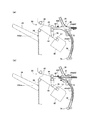
[端面綴じのための待機搬送]
まず、図7から図9により第1処理トレイ54に集積してシート束に端面綴じするために搬送ローラ44を逆転して分岐経路70に待機し、その後再び第1処理トレイ54側に搬送する「待機搬送」について説明する。
図7から図9では端面綴じに比較的良く使用されるA4ヨコの場合を例にし、SLは搬送経路42のシートセンサ42Sから出口ローラ48の出口位置(第1処理トレイ出口50)迄の距離を示している。この実施態様にあっては、SLは120ミリから130ミリとしている。したがって、シートはこのSLの倍弱の長さであり、図6(a)の様に約半分弱が機外にはみ出る状状態となる。
The above points will be described with reference to the flow charts of FIGS. 7 to 11 and the flowchart of FIG.
[Standby transport for end face binding]
First, the conveying roller 44 is reversely rotated to wait on the branch path 70 in order to be stacked on the first processing tray 54 and bound to the sheet bundle in accordance with FIGS. 7 to 9, and then conveyed again to the first processing tray 54 side. “Standby conveyance” will be described.
7 to 9 exemplify the case of A4 horizontal that is used comparatively well for end face binding, and SL is the distance from the sheet sensor 42S of the conveyance path 42 to the outlet position of the outlet roller 48 (first processing tray outlet 50). Is shown. In this embodiment, SL is 120 mm to 130 mm. Accordingly, the sheet has a length slightly less than twice that of SL, and as shown in FIG.

まず、図7(a)は、端面綴じするための1枚目シート(sheet1)が搬送経路上を約1100mm/sで搬送され、そのシート後端がシートセンサ42Sに検出されると、搬送ローラ44は一旦停止し、今度はシートを逆送してスイッチバック搬送するように搬送ローラモータ44Mを逆転に切り替える。このときシートの先端側は上述したように半分弱程度が機外にはみ出している状態となっている。 First, FIG. 7A shows a case where the first sheet (sheet 1) for end-face binding is conveyed at about 1100 mm / s on the conveyance path, and the conveyance roller is detected when the sheet sensor 42S detects the trailing edge of the sheet. 44 temporarily stops, and this time, the conveyance roller motor 44M is switched to reverse rotation so as to reversely feed the sheet and carry it back in switchback. At this time, the front end side of the sheet is in a state where a little less than half protrudes outside the apparatus as described above.

次に、図7(b)に示す様に、搬送ローラモータ44Mの逆転に先立ち、先立ち切り替えゲート37を図示実線位置に移動する。搬送ローラ44によりシートは分岐経路70側に搬送され、搬送ローラモータ44Mによって回転する
分岐ローラ72によって分岐経路70下流側に向かって搬送する。この際の搬送ローラモータ44Mの搬送速度もシートを1100mm/sによって搬送するように高速に設定されている。もちろん、搬送ローラモータ44Mは正転から逆転の際に一旦停止するので、この1100mm/sを搬送目標速度して設定されており、平均速度はもう少し遅くなるが、画像形成装置画からのシート搬入に間に合うように高速搬送している。
Next, as shown in FIG. 7B, prior to the reverse rotation of the transport roller motor 44M, the switching gate 37 is moved to the position indicated by the solid line. The sheet is conveyed to the branch path 70 side by the conveyance roller 44 and conveyed toward the downstream side of the branch path 70 by the branch roller 72 rotated by the conveyance roller motor 44M. The conveyance speed of the conveyance roller motor 44M at this time is also set to a high speed so as to convey the sheet at 1100 mm / s. Of course, since the conveyance roller motor 44M temporarily stops at the time of forward rotation from the normal rotation, this 1100 mm / s is set as the conveyance target speed, and the average speed is a little slower, but the sheet is carried in from the image forming apparatus image. It is transported at high speed in time.

図8(a)は、スイッチバック搬送した先のシート(sheet1)の後端が分岐位置36で次シート(sheet2)の搬入の妨げのならない位置に達すると搬送ローラモータ44Mを停止する。これにより分岐ローラ72も停止、先のシートは分岐経路70で待機次シートの搬入を待つ。次シート(sheet2)は、搬入ローラモータ34Mにより、1100mm/sで搬入経路32から搬送経路42に向かって搬送される。   In FIG. 8A, the transport roller motor 44M is stopped when the rear end of the previous sheet (sheet 1) that has been switched back reaches the position at which the next sheet (sheet 2) is not hindered at the branch position 36. As a result, the branch roller 72 is also stopped, and the preceding sheet waits for the standby next sheet to be carried in the branch path 70. The next sheet (sheet 2) is transported from the transport path 32 toward the transport path 42 at 1100 mm / s by the transport roller motor 34M.

引き続き、図8(b)で、次のシートの搬送経路42への到達に先立ち、切り替えゲート37を図示の様にエスケープ経路を塞ぐ位置に移動して置く。これにより次のシート(sheet2)は搬送経路42に搬送される。これと合わせて分岐経路70に待機しておいた先のシート(sheet1)と重ねて搬送できるように搬送する。この際、図示の様に、次のシート(sheet2)の先端に対して、多少後方側にずらして先のシート(sheet1)を搬送するようにしている。次に示す様に、第1処理トレイ54に搬入した際に最も上のシート(かき込みコロ56に近いシート)が基準面57から遠く位置することにより、かき込みコロ56の回転で精度よく複数のシートが基準面57で揃うことになる。
なお、この2枚を重ね合わせる際には、搬入ローラモータ34M及び搬送ローラモータ44Mとも1100mm/sを搬送到達速度として同速でシートを搬送するように設定されている。
Subsequently, in FIG. 8B, prior to the arrival of the next sheet on the conveyance path 42, the switching gate 37 is moved to a position for closing the escape path as shown. As a result, the next sheet (sheet 2) is conveyed to the conveyance path 42. At the same time, the sheet is conveyed so that it can be conveyed in an overlapped manner with the previous sheet (sheet 1) waiting on the branch path 70. At this time, as shown in the drawing, the preceding sheet (sheet 1) is conveyed with a slight shift to the rear side with respect to the leading end of the next sheet (sheet 2). As shown below, when the uppermost sheet (sheet close to the biting roller 56) is positioned far from the reference surface 57 when it is carried into the first processing tray 54, a plurality of sheets are accurately obtained by the rotation of the biting roller 56. Are aligned on the reference plane 57.
When the two sheets are overlapped, both the carry-in roller motor 34M and the carry roller motor 44M are set to carry the sheet at the same speed with a carry arrival speed of 1100 mm / s.

次に、図9(a)の状態に進み、重なった2枚のシートが搬送ローラ44から放出される前に、出口ローラ48の出口上ローラ48aが出口ローラ48bに向かって下降してシートをニップする。このとき出口ローラ48は搬送ローラ44と同速で搬送し、シートが搬送ローラ44から放出されると、一旦停止する。この停止後、今度は出口ローラ48を第1処理トレイ54の基準面57側に回転駆動する。これにより2枚のシート(sheet1と2)は、基準面57側に第1処理トレイ54の載置面上を搬送され引き続き、搬送ローラモータ44Mにワンウェイクラッチ付ギア144を介して駆動されるかき込みコロ56によって引き続き搬送される。なお、出口ローラ48の基準面57側への搬送は1100mm/sの回転から600mm/s程度に減速して搬送すると整合がしやすい。   Next, the process proceeds to the state shown in FIG. 9A, and before the two overlapped sheets are discharged from the conveying roller 44, the outlet upper roller 48a of the outlet roller 48 descends toward the outlet roller 48b to remove the sheet. Nip. At this time, the exit roller 48 transports at the same speed as the transport roller 44, and once the sheet is discharged from the transport roller 44, it stops. After this stop, this time, the exit roller 48 is rotationally driven to the reference surface 57 side of the first processing tray 54. As a result, the two sheets (sheets 1 and 2) are conveyed on the mounting surface of the first processing tray 54 to the reference surface 57 side, and are continuously driven by the conveying roller motor 44M via the one-way clutch gear 144. It is continuously conveyed by the roller 56. In addition, the conveyance to the reference surface 57 side of the exit roller 48 is easy to be aligned if the conveyance is decelerated from the rotation of 1100 mm / s to about 600 mm / s.

図9(b)は、3枚目のシート(sheet3)が、第1処理トレイ54に搬入される状態を示している。この場合も、上記同様に3枚目のシートが搬送ローラ44から放出される前に、出口上ローラ48aを下降して搬送ローラ44と同じ方向に回転し、シートが放出後に今度は回転方向を逆にして、かき込みコロ56とともに基準面57側に移送する。これを指定した枚数になるまで繰り返して、1つの束として生成し、端面綴じユニット62で綴じ処理後に第1排紙トレイ24は束排紙する。
以上の様に、図6から図8の端面綴じのための待機搬送では搬送ローラ44のスイッチバック搬送速度は1100mm/sをその設定速度として高速搬送を行っている。
FIG. 9B shows a state where the third sheet (sheet 3) is carried into the first processing tray 54. In this case as well, before the third sheet is ejected from the transport roller 44, the upper exit roller 48a is lowered and rotated in the same direction as the transport roller 44. On the contrary, it is transferred to the reference surface 57 side together with the scraping roller 56. This is repeated until the designated number of sheets is reached, and is generated as one bundle. After the binding process by the end face binding unit 62, the first discharge tray 24 discharges the bundle.
As described above, in the standby conveyance for end face binding in FIGS. 6 to 8, the switchback conveyance speed of the conveyance roller 44 is high-speed conveyance with the set speed being 1100 mm / s.

また、補助ガイド110は図7から図9にあるように、第1処理トレイ54下の収納位置に位置している。加えて、第1排紙トレイ24の載置面またはこれに載置されたシート上面を図5、図6に示すシート受け位置24Smより下降した離間位置24Slに位置させると、待機搬送をするスイッチバックシートの先端が第1排紙トレイ24の載置面またはこれに載置されたシート上面から離間して当接することがなくシート先端の座屈を回避できる。 Further, as shown in FIGS. 7 to 9, the
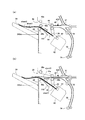
 auxiliary guide 110 is located at the storage position below the first processing tray 54. In addition, when the placement surface of the first discharge tray 24 or the upper surface of the sheet placed thereon is positioned at the separation position 24S1 that is lowered from the sheet receiving position 24Sm shown in FIGS. The back end of the back sheet does not come into contact with and separate from the mounting surface of the first paper discharge tray 24 or the upper surface of the sheet mounted thereon, so that buckling of the front end of the sheet can be avoided.

[中綴じための第2トレイ搬送]
次に、図10、図11により第2トレイ(第2処理トレイ)としてのスタッカ84にシートを集積してシート束のシート搬送方向中程に中綴じするために、搬送ローラ44を逆転し、シートをスイッチバック搬送して分岐経路70を介してスタッカに送る「第2トレイ搬送」について説明する。
図10、図11では中綴じで比較的良く使用されるA3シートの場合を例にし、先の端面綴じ同様にSLは搬送経路42のシートセンサ42Sから出口ローラ48の出口位置(第1処理トレイ出口50)迄の距離を示している。この実施態様にあっては、SLは120ミリから130ミリなので、中綴じ用のシートはこのSLの3倍半程度の長さであり、図10(a)の様に約3分の2以上が機外にはみ出る状状態となる。
[2nd tray transport for saddle stitching]
Next, in order to stack sheets in the stacker 84 as a second tray (second processing tray) according to FIGS. 10 and 11 and to perform saddle stitching in the middle of the sheet conveying direction of the sheet bundle, the conveying roller 44 is reversed, The “second tray conveyance” in which the sheet is conveyed back to the stacker via the branch path 70 will be described.
10 and 11 exemplify the case of an A3 sheet that is used comparatively well in saddle stitching, and SL is similar to the above-described end face binding, and SL is positioned from the sheet sensor 42S of the conveyance path 42 to the exit position of the exit roller 48 (first processing tray). The distance to the exit 50) is shown. In this embodiment, since SL is 120 mm to 130 mm, the sheet for saddle stitching is about three and a half times as long as this SL. As shown in FIG. Will be out of the plane.

まず、図10(a)は、中綴じをするためスタッカ84に分岐経路70を介して第2トレイ搬送を行うことを示し、1枚目シート(sheet1)が搬送経路42上を約1100mm/sで搬送され、そのシート後端がシートセンサ42Sに検出されると、搬送ローラ44は一旦停止し、今度はシートを逆送するように搬送ローラモータ44Mを逆転に切り替える。このときシートの先端側は上述したように3分の2以上が機外にはみ出している状態となっている。 First, FIG. 10A shows that the second tray is conveyed to the stacker 84 via the branch path 70 for saddle stitching, and the first sheet (sheet 1) is about 1100 mm / s on the conveyance path 42. When the trailing edge of the sheet is detected by the sheet sensor 42S, the conveyance roller 44 is temporarily stopped, and this time, the conveyance roller motor 44M is switched to reverse rotation so as to reversely feed the sheet. At this time, as described above, two-thirds or more of the leading end side of the sheet protrudes outside the apparatus.

また、補助ガイド110が上記スイッチバック搬送するシートをガイドするように、図3または図6に示した補助ガイドモータ110Mを、1枚目シートが第1処理トレイ出口50から搬送される(はみ出す)前に図示矢印方向に駆動する。したがって、補助ガイド110は、第1排紙トレイ24の載置面またはこの載置面にシートが載置されている場合はこのシート上面の上方の案内位置に位置する。これにより、第1処理トレイ出口50に於ける第1排紙トレイ24載置面またはこれに載置されたシート上面との立ち面28の段差が少なくでき、この補助ガイド110にスイッチバックするシートがガイドされてバタつきや曲がりが抑えられる。 Further, the first sheet is conveyed from the first processing tray outlet 50 by the auxiliary guide motor 110M shown in FIG. 3 or 6 so that the auxiliary guide 110 guides the sheet to be conveyed by the switchback. Drive in the direction of the arrow in the figure before. Therefore, the auxiliary guide 110 is positioned at the guide surface above the upper surface of the sheet when the sheet is placed on the placement surface of the first discharge tray 24 or the placement surface. As a result, the level difference between the first discharge tray 24 placement surface at the first processing tray outlet 50 and the standing surface 28 with respect to the upper surface of the sheet placed thereon can be reduced, and the sheet to be switched back to the auxiliary guide 110. Is guided to prevent fluttering and bending.

次に、図10(b)に示す様に、搬送ローラモータ44Mの逆転に先立ち、先立ち切り替えゲート37を図示の位置に移動する。搬送ローラ44によりシートは分岐経路70側に搬送され、搬送ローラモータ44Mによって回転する分岐ローラ72によって分岐経路70下流側に向かって搬送する。この際の搬送ローラモータ44Mの搬送速度もシートを600mm/s減速して搬送するように低速に変更するように設定されている。
そして、この1枚目のシート(sheet1)が同速度の600mm/sで回転している分岐ローラ72にニップされると、切り替えゲート37を、搬送経路42を解放する位置(エスケープ経路を塞ぐ位置)に移動する。これとともに搬送ローラ44の搬送上ローラ44aを搬送下ローラ44bから離間して次のシート(sheet2)の搬入を待つ。また、補助ガイド110は、第1排紙トレイ24の載置面または載置シート上面の上方の案内位置でスイッチバックするシートを案内ガイドしている。
Next, as shown in FIG. 10B, prior to the reverse rotation of the transport roller motor 44M, the switching gate 37 is moved to the illustrated position. The sheet is conveyed to the branch path 70 side by the conveyance roller 44 and conveyed toward the downstream side of the branch path 70 by the branch roller 72 rotated by the conveyance roller motor 44M. The conveyance speed of the conveyance roller motor 44M at this time is also set to be changed to a low speed so as to convey the sheet by decelerating it by 600 mm / s.
When the first sheet (sheet 1) is nipped by the branch roller 72 rotating at the same speed of 600 mm / s, the switching gate 37 is moved to a position for releasing the conveyance path 42 (position for closing the escape path). ) At the same time, the upper conveying roller 44a of the conveying roller 44 is separated from the lower conveying roller 44b and waits for the next sheet (sheet 2) to be carried. The auxiliary guide 110 guides the sheet to be switched back at the guide position above the placement surface of the first discharge tray 24 or the top surface of the placement sheet.

なお、搬送ローラモータ44Mは正転から逆転の際に一旦停止するので、上記の600mm/sを搬送目標速度して設定されており、平均速度はもう少し遅くなるが、この速度を設定値として減速している。また、スイッチバック搬送時に1100mm/sから600mm/sに減速しているは、シートの戻り搬送であるスイッチバック搬送時に、特にシートのバタつきが多く、比較的長い距離を搬送するので特に戻り時に減速しているが、処理速度が特に高速でなければ、上記紙シートが機外に排出される往復搬送において、1100mm/sから600mm/sに減速してもよい。 Note that the conveyance roller motor 44M temporarily stops at the time of forward rotation to reverse rotation, so the above-mentioned 600 mm / s is set as the conveyance target speed, and the average speed is a little slower. doing. Further, the speed is reduced from 1100 mm / s to 600 mm / s during the switchback conveyance. When the switchback conveyance is the sheet return conveyance, the sheet is particularly fluttered and is conveyed over a relatively long distance. Although the speed is reduced, if the processing speed is not particularly high, the paper sheet may be decelerated from 1100 mm / s to 600 mm / s in the reciprocating conveyance in which the paper sheet is discharged out of the apparatus.

次に、図11(a)では、次のシート(sheet2)が搬入ローラ34によって搬送経路42に搬送される。この場合、搬送ローラ44は図示の様に離間状態となっているので、先の1枚目シート(sheet1)は、分岐ローラ72と分岐出口ローラ74により600mm/sでスタッカ84に搬送され、次の2枚目シート(sheet2)は、搬送経路42を搬入ローラ34により第1処理トレイ54側に向かって1100mm/sで搬送される。この場合、2枚のシートは夫々反対方向にすれ違いながら搬送(すれ違い搬送)される。
このすれ違い搬送は、先のシートを減速して搬送するため、次シートの待機時間をなくしたり、あるいは少なくしたりするために行われる。また、第1排紙トレイ24の載置面または載置シート上面には補助ガイド110が案内位置に延設されていて、立ち面28における段差を少なくしスイッチバックするシートを案内ガイドしている。
Next, in FIG. 11A, the next sheet (sheet 2) is conveyed to the conveyance path 42 by the carry-in roller 34. In this case, since the conveying roller 44 is in a separated state as shown in the drawing, the first sheet (sheet 1) is conveyed to the stacker 84 by the branch roller 72 and the branch outlet roller 74 at 600 mm / s, and next The second sheet (sheet 2) is conveyed at 1100 mm / s along the conveyance path 42 toward the first processing tray 54 side by the carry-in roller 34. In this case, the two sheets are conveyed while being passed in opposite directions (passed conveyance).
This passing conveyance is performed in order to eliminate or reduce the waiting time of the next sheet in order to decelerate and convey the previous sheet. Further, an auxiliary guide 110 is extended to the guide position on the placement surface or the top surface of the placement sheet of the first discharge tray 24, and guides and guides the sheet to be switched back by reducing the level difference on the standing surface 28. .

そして、図11(b)では、先のシートが分岐ローラ72から離脱してスタッカ84に収納状態となるので、搬送上ローラ44aを下降し搬送ローラ44をニップ状態として第1排紙トレイ24側にシートを1100mm/sの速度で搬送する。この後、引き続き図10(a)の状態でシートを搬送し、これを指定した枚数になるまで繰り返して、スタッカ84に1つの束として生成する。そして、このシート束を図2に示したストッパ85により、中綴じユニット82の綴じ位置に移動して中綴じ処理を行う。
以上の様に、図10、図11の中綴じのための第2トレイ搬送では搬送ローラ44のスイッチバック搬送速度は600mm/sをその設定速度として減速搬送を行う。また、第1排紙トレイ24の載置面または載置シート上面の上方に補助ガイド110を延設させ、スイッチバックするシートを案内ガイドしシートのスイッチバック搬送時のバタつきや曲がりを少なくしている。
In FIG. 11B, since the preceding sheet is detached from the branch roller 72 and stored in the stacker 84, the upper conveying roller 44a is lowered to bring the conveying roller 44 into the nip state, and the first discharge tray 24 side. The sheet is conveyed at a speed of 1100 mm / s. Thereafter, the sheet is continuously conveyed in the state of FIG. 10A, and this is repeated until the designated number of sheets is reached, and is generated as one bundle in the stacker 84. Then, the sheet bundle is moved to the binding position of the saddle stitching unit 82 by the stopper 85 shown in FIG.
As described above, in the second tray conveyance for saddle stitching in FIGS. 10 and 11, the switchback conveyance speed of the conveyance roller 44 is decelerated and conveyed at a set speed of 600 mm / s. In addition, the auxiliary guide 110 is extended above the placement surface of the first discharge tray 24 or the upper surface of the placement sheet to guide and guide the sheet to be switched back, thereby reducing flutter and bending at the time of sheet switchback conveyance. ing.

(待機搬送の変形例…待機搬送時の補助ガイド延設)
ここで、図7から図9における端面綴じの際の待機搬送の別の実施態様(変形例)を図12により説明する。図12は図7と同じく待機搬送を行うために搬送ローラ44によりスイッチバック搬送を開始することを示し、図12(a)は搬送経路でスイッチバックを開始する説明図。図12(b)は引き続き、搬送経路から分岐経路に搬送している状態を示している。この場合、図7にあっては、補助ガイド110が第1処理トレイ54下方に収納された収納位置に位置されているが、この図12の変形例にあっては、第1排紙トレイ24の載置面または載置面のシート上面に補助ガイド110を延設してある。この待機搬送を行うシートは、機外に露出する搬送長さが比較的短いので、第2トレイ搬送時の比較的長いシートほどのバタや曲がりは発生しないが、ここでも第1処理トレイ出口からの立ち面28の段差が少なくなるので、よりスムーズなスイッチバック搬送が期待できる。
以上の様に、この変形例にあっては、比較的短いシートを使用する待機搬送の際も補助ガイド110を案内位置に延設してシートを安定的に搬送するようにしている。
(Variation of standby transport: Auxiliary guide extension during standby transport)
Here, another embodiment (variation example) of standby conveyance at the time of end-face binding in FIGS. 7 to 9 will be described with reference to FIG. FIG. 12 shows that switchback conveyance is started by the conveyance roller 44 in order to perform standby conveyance as in FIG. 7, and FIG. 12A is an explanatory diagram for starting switchback in the conveyance path. FIG. 12B shows a state in which the transfer route is continuously transferred from the transfer route. In this case, in FIG. 7, the auxiliary guide 110 is positioned at the storage position stored below the first processing tray 54, but in the modified example of FIG. 12, the first paper discharge tray 24. The auxiliary guide 110 is extended on the mounting surface or the sheet upper surface of the mounting surface. Since the sheet to be transported in the standby mode has a relatively short conveyance length exposed to the outside of the apparatus, it does not generate a flutter or bend as much as a relatively long sheet during the second tray conveyance. Therefore, smoother switchback conveyance can be expected.
As described above, in this modification, the auxiliary guide 110 is extended to the guide position so that the sheet can be stably conveyed even during standby conveyance using a relatively short sheet.

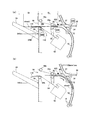
(第2トレイ搬送の変形例…第1排紙トレイ24の上昇)
図13は、図10に示した中綴じ処理のためスタッカ84(第2トレイ)にシートを収納するための第2トレイ搬送の際に第1排紙トレイ(排紙トレイ)を上昇させた変形例の説明図である。図13(a)は搬送経路でスイッチバックを開始し、図13(b)は引き続き、搬送経路から分岐経路に搬送している状態を示している。
この第2トレイ搬送の際に、補助ガイド110を第1排紙トレイ24の載置面または載置面に載置されたシート上方の案内位置に延設することは図10及び図11と同様であるが、これにさらに図12に図示の様に第1排紙トレイ24の載置面または載置面上のシートを排出するシートを受け入れるシート受け位置24Sm(二点鎖線位置)からガイド位置24Sh側に上昇した上昇位置(実線位置)に移動させてある。この上昇位置へは、図3及び図5の第1排紙トレイ24を昇降する昇降モータ24Mを、1枚目シートが第1処理トレイ出口50から搬送される(はみ出す)前に、第1処理トレイ出口50に最も近づく方向に上昇駆動して行う。この上昇により、上方にある補助ガイド110の先端当接部116との間の隙間がなくなり、スイッチバック搬送されるシートは、第1排紙トレイ24載置面あるいは載置面に積載されたシート及び補助ガイド110と、この位置での段差を解消して、よりシートのスイッチバック搬送をバタつきなくスムーズに行うことがでる。
(Modification of Second Tray Transport: Raising First Paper Discharge Tray 24)
FIG. 13 shows a modification in which the first discharge tray (discharge tray) is raised during the second tray conveyance for storing sheets in the stacker 84 (second tray) for the saddle stitching process shown in FIG. It is explanatory drawing of an example. FIG. 13A shows a state in which switchback is started on the transfer route, and FIG. 13B shows a state where transfer is continued from the transfer route to the branch route.
As in FIGS. 10 and 11, the auxiliary guide 110 is extended to the placement surface of the first discharge tray 24 or the guide position above the sheet placed on the placement surface during the second tray conveyance. However, as shown in FIG. 12, the guide position from the sheet receiving position 24Sm (two-dot chain line position) for receiving the sheet for discharging the sheet on the mounting surface of the first sheet discharge tray 24 or the sheet on the mounting surface. It has been moved to the raised position (solid line position) raised to the 24Sh side. To this raised position, the lifting / lowering motor 24M that lifts and lowers the first discharge tray 24 of FIGS. 3 and 5 performs the first process before the first sheet is conveyed (extruded) from the first processing tray outlet 50. This is done by driving up in the direction closest to the tray outlet 50. As a result of this rise, there is no gap between the upper end guide portion 116 of the auxiliary guide 110 and the sheet to be conveyed in the switchback is the sheet placed on the first discharge tray 24 placement surface or the placement surface. In addition, the auxiliary guide 110 and the step at this position are eliminated, and the switchback conveyance of the sheet can be performed smoothly without fluttering.

ここで、これまで説明した図7から図9の待機搬送及び図10と図11についての搬送速度切り替えについて、図14の流れ図により確認する。また、これと異なるシートサイズを考慮した他の実施態様を図15により説明する。
[端面綴じか中綴じによるスイッチバック速度の減速]
まず、図14に示す様に、画像形成部2のコントロールパネル18から「スル端面綴じモード」「中綴じモード」が設定されると、これを確認する(Step10)。これが端面綴じである場合は、比較的長さの短いシートが多用されるので、スイッチバック搬送の速度を1100mm/sのまま行う(Step20)。これにより、例えば、1枚から3枚でまで一旦スイッチバック搬送して分岐経路70に待機(分岐経路待機)させ、後続シートと合わせて再び第1処理トレイ54側にスイッチバック搬送する。この際、補助ガイド110は第1処理トレイ54下の収納位置に収納されている。この待機搬送が完了すると終了し次の工程に移行する。
Here, the standby conveyance in FIGS. 7 to 9 described above and the conveyance speed switching in FIGS. 10 and 11 are confirmed with reference to the flowchart in FIG. Another embodiment in consideration of a different sheet size will be described with reference to FIG.
[Deceleration of switchback speed by edge binding or saddle stitching]
First, as shown in FIG. 14, when “through end surface binding mode” and “saddle binding mode” are set from the control panel 18 of the image forming unit 2, this is confirmed (Step 10). If this is end-face stitching, a sheet with a relatively short length is frequently used, so the switchback conveyance speed is kept at 1100 mm / s (Step 20). As a result, for example, one to three sheets are once switched back and conveyed to wait on the branch path 70 (branch path standby), and are then switched back and conveyed to the first processing tray 54 side together with the subsequent sheets. At this time, the auxiliary guide 110 is stored in the storage position below the first processing tray 54. When this standby conveyance is completed, the process ends and the process proceeds to the next step.

次に、中綴じが確認(Step10)されると、比較的長さの長いシートが多用されるとして、搬送ローラ44によるスイッチバック搬送速度を図9で説明したように、1100mm/sから600mm/sに速度を減速してスイッチバック搬送を行う(Step40)。スタッカ84に搬入して束とする後続シートの有無を確認する(Step50)。完了せず、束とすべき後続シートがある場合には、図10(b)に示すすれ違い搬送実行する。この際、補助ガイド110は、第1排紙トレイ24の載置面またこれに載置されたシート上方の案内位置に延設されては搬送されるスイッチバックシートのバタつきを抑えスムーズに案内する。以後、束とする後続シートがない場合は、第2トレイ搬送の処理が完了したとして、中綴じなど次の工程に移行する。   Next, when saddle stitching is confirmed (Step 10), it is assumed that a relatively long sheet is frequently used, and the switchback conveyance speed by the conveyance roller 44 is 1100 mm / s to 600 mm / s as described in FIG. The speed is reduced to s and the switchback conveyance is performed (Step 40). The presence / absence of a subsequent sheet that is carried into the stacker 84 to be bundled is confirmed (Step 50). If there is a succeeding sheet to be bundled without being completed, the passing conveyance shown in FIG. 10B is executed. At this time, the auxiliary guide 110 guides smoothly by suppressing the fluttering of the switchback sheet conveyed by extending to the guide surface above the placement surface of the first discharge tray 24 or the sheet placed thereon. To do. Thereafter, when there is no subsequent sheet to be bundled, it is determined that the second tray conveyance process is completed, and the process proceeds to the next process such as saddle stitching.

[変形例…端面綴じと中綴じにおけるシートサイズでの速度変更]
次に、図15の流れ図により図14で説明した実施態様の変形例にについて説明する。
これまで図14迄の実施の態様にあっては、綴じモードが第1処理トレイ54上のシート束の端面を綴じる端面綴じか、スタッカ84に集積されたシート束を綴じる中綴じかにより、一律スイッチバック搬送の速度を1100mm/sのまま行うか、1100mm/sから600mm/sに減速して行うか選択していた。これでもおおよその処理はカバーできるが、端面綴じであっても搬送距離間の長いシートがあり、一方中綴じであっても比較的短いシートを処理することが発生する。
図15のフローを採用することによって、端面綴じ時の比較的長いシート、または中綴じ時の比較的短いシートも安定して送るようにしたものである。
[Variation: Speed change by sheet size in end face binding and saddle stitching]
Next, a modification of the embodiment described with reference to FIG. 14 will be described with reference to the flowchart of FIG.
Until now, in the embodiment up to FIG. 14, whether the binding mode is end-face binding for binding the end face of the sheet bundle on the first processing tray 54 or saddle-stitching for binding the sheet bundle accumulated in the stacker 84 is uniform. It has been selected whether the switchback conveyance speed is kept at 1100 mm / s or is reduced from 1100 mm / s to 600 mm / s. Even in this case, the rough processing can be covered, but there is a long sheet between the conveyance distances even in the case of end-face stitching, whereas a relatively short sheet occurs even in the case of saddle stitching.
By adopting the flow of FIG. 15, a relatively long sheet at the time of end binding or a relatively short sheet at the time of saddle stitching is stably fed.

[端面綴じ時のシートサイズによる速度変更]
すなわち、画像形成部2のコントロールパネル18から「端面綴じモード」「中綴じモード」が設定されると、これを確認する(Step100)。これが端面綴じである場合には、図示左側に進み、端面綴じを行うシートの長さが所定長さより長いか否かを確認する(Step110)。この変形にあっては、シートサイズがB5、A4ヨコ、レターの場合は短いと設定し、これを越える例えば、A3、B4、リーガル及びA4タテの長さを長いと設定している。そして、短い場合には、スイッチバック搬送の速度を1100mm/sのまま行う(Step120)。これにより、例えば1枚から3枚でまで一旦スイッチバック搬送して分岐経路70に待機(分岐経路待機)させ、再び第1処理トレイ54側にスイッチバック搬送する。この際、補助ガイド110は第1処理トレイ54下の収納位置に収納されている。この待機搬送が完了すると終了し、次の工程に移行する。
なお、この変形例におけるシートサイズ(シート長さ)の認識は画像形成制御部200からサイズ情報を得て設定する。あるいはシート処理装置Bの搬入口30付近にサイズ検出のセンサを配置して検出して良い。このシートサイズの認識はシートセンサがシートの存在する時間を検出したり、シートカセット1aで指定したりするなど、広く知られているでここでの説明を省略する。
[Change speed depending on sheet size when binding edge]
That is, when “end face stitching mode” and “saddle stitching mode” are set from the control panel 18 of the image forming unit 2, this is confirmed (Step 100). If this is end face binding, the process proceeds to the left side in the figure, and it is confirmed whether or not the length of the sheet to be subjected to end face binding is longer than a predetermined length (Step 110). In this modification, when the sheet size is B5, A4 width and letter, the length is set to be short, and for example, the lengths of A3, B4, legal and A4 lengths exceeding this are set to be long. If it is short, the switchback conveyance speed is kept at 1100 mm / s (Step 120). As a result, for example, one to three sheets are temporarily switched back and transferred to the branch path 70 (standby for the branch path), and then switched back to the first processing tray 54 side again. At this time, the auxiliary guide 110 is stored in the storage position below the first processing tray 54. When this standby conveyance is completed, the process ends and the process proceeds to the next step.
Note that the recognition of the sheet size (sheet length) in this modification is set by obtaining size information from the image formation control unit 200. Alternatively, a size detection sensor may be disposed near the carry-in entrance 30 of the sheet processing apparatus B for detection. The recognition of the sheet size is widely known, for example, when the sheet sensor detects the time when the sheet exists or is designated by the sheet cassette 1a, and the description thereof is omitted here.

一方、上記でシート長さが長いとされると、搬送ローラ44によるスイッチバック搬送速度を1100mm/sから600mm/sに速度を減速してスイッチバック搬送を行う(Step140)。この場合、この待機搬送を後続シートとの間で行うときには、先行シートが分岐ローラ72にニップされたことを確認して次のシートとの間ですれ違い搬送を実施する(Step160)。この際、補助ガイド110は、第1排紙トレイ24の載置面またこれに載置されたシート上方の案内位置に延設して、スイッチバック搬送されシートを案内する。
この待機搬送が完了すると終了し、次の工程に移行する。
On the other hand, if the sheet length is long as described above, the switchback conveyance speed by the conveyance roller 44 is reduced from 1100 mm / s to 600 mm / s, and the switchback conveyance is performed (Step 140). In this case, when this standby conveyance is performed with the succeeding sheet, it is confirmed that the preceding sheet has been nipped by the branching roller 72, and the conveyance with the next sheet is performed (Step 160). At this time, the auxiliary guide 110 extends to the placement surface of the first discharge tray 24 or a guide position above the sheet placed on the first discharge tray 24 and guides the sheet by being switched back.
When this standby conveyance is completed, the process ends and the process proceeds to the next step.

[中綴じ時でのシートサイズによる速度変更]
「端面綴じモード」「中綴じモード」が設定され、中綴じである場合には、図示右側に進み、中綴じを行うシートの長さが所定長さより長いか否かを確認する(Step170)。この変形にあっては、シートサイズがA4タテの場合は短いと設定し、これを例えば、A3、B4、リーガルは長いと設定している。ここで端面綴じでは長いとしていたA4タテを、この中綴じではあえて短いとして設定している。これは、中綴じおけるA4タテサイズは中綴じを行うシート長さにあっては短いシートの方に分類され、比較的高速処理が求められ易く、また分岐ローラ72が正逆転のために停止することなく回転するので整合性もそれほど悪化しないため、端面綴じと判断基準を変えている。
[Speed change due to sheet size during saddle stitching]
If “end stitching mode” and “saddle stitching mode” are set and the saddle stitching mode is set, the process proceeds to the right side in the figure to check whether the length of the sheet to be saddle stitched is longer than a predetermined length (Step 170). In this modification, when the sheet size is A4 vertical, it is set as short, and for example, A3, B4, and legal are set as long. Here, the A4 length that is long in the end face binding is set to be short in the saddle stitching. This is because the A4 vertical size for saddle stitching is classified as a shorter sheet in the sheet length for saddle stitching, and relatively high speed processing is required, and the branch roller 72 stops due to forward and reverse rotation. Since it rotates without any problem, the consistency does not deteriorate so much.

この中綴じシートのシート長さが短い、本変形例では、A4タテの場合にはスイッチバック搬送の速度を1100mm/sのまま行う(Step180)。これにより中綴じシートがスタッカ84に搬入が完了したと判断する(Step190)、この第2トレイ搬送が完了したとして、次の工程に移行する。この際、補助ガイド110は第1処理トレイ54下の収納位置に収納されている。
上記でシート長さが長いとされると、搬送ローラ44によるスイッチバック搬送速度を1100mm/sから600mm/sに速度を減速してスイッチバック搬送を行う(Step200)。この場合、第2トレイ搬送を後続シートとの間で行うことを確認(Step210)し、先行シートが分岐ローラ72にニップされた後に次のシートとの間ですれ違い搬送を実施する(Step220)。
この際、補助ガイド110は、第1排紙トレイ24の載置面またこれに載置されたシート上方の案内位置に延設されて、スイッチバック搬送のシートを案内する。以後、束とする後続シートがない場合は、第2トレイ搬送の処理が完了したとして、中綴じなど次の工程に移行する。
In this modification in which the sheet length of the saddle stitching sheet is short, in the case of A4 length, the switchback conveyance speed is kept at 1100 mm / s (Step 180). As a result, it is determined that the saddle stitched sheet has been carried into the stacker 84 (Step 190). If the second tray conveyance is completed, the process proceeds to the next step. At this time, the auxiliary guide 110 is stored in the storage position below the first processing tray 54.
If the sheet length is long as described above, the switchback conveyance speed by the conveyance roller 44 is reduced from 1100 mm / s to 600 mm / s to perform switchback conveyance (Step 200). In this case, it is confirmed that the second tray is conveyed with the succeeding sheet (Step 210), and after the preceding sheet is nipped by the branch roller 72, the sheet is conveyed with the next sheet (Step 220).
At this time, the auxiliary guide 110 is extended to the placement surface of the first discharge tray 24 or a guide position above the sheet placed thereon to guide the switchback transport sheet. Thereafter, when there is no subsequent sheet to be bundled, it is determined that the second tray conveyance process is completed, and the process proceeds to the next process such as saddle stitching.

以上の様に、上記の変形例にあっては、端面綴じかまたは中綴じかによって、搬送ローラ44によるスイッチバック搬送の速度を変えるのではなく、端面綴じまたは中綴じの何れにおいてもシート長さを確認して上記のスイッチバック速度を変えたものである。さらに、例えば端面綴じのA4タテと中綴じのA4タテの同じ長さであっても最も適したスイッチバック速度を設定してするとともに、第1排紙トレイ24の載置面または載置されたシート上方に補助ガイド110を案内位置に延設しスイッチバックシートをガイドして安定搬送と高速化を両立させている。   As described above, in the above modified example, the sheet length is not changed in the end face binding or the saddle stitching, but the speed of the switchback conveyance by the transport roller 44 is not changed depending on the end face binding or the saddle stitching. The above switchback speed was changed after confirming the above. Further, for example, the most suitable switchback speed is set even when the A4 length of the end face binding and the A4 length of the saddle stitching are the same length, and the placement surface or the placement surface of the first discharge tray 24 is placed. The auxiliary guide 110 is extended to the guide position above the sheet and the switchback sheet is guided to achieve both stable conveyance and high speed.

[制御構成の説明]
上述した画像形成装置のシステム制御構成を図12のブロック図に従って説明する。図1に示す画像形成装置のシステムは画像形成装置Aの画像形成制御部200とシート処理装置Bのシート処理制御部204(制御CPU)を備えている。画像形成制御部200は、給紙制御部202と入力部203を備えている。そしてこの入力部203に設けられたコントロールパネル18から「プリントモード」「シート処理モード」の設定を行うことは既に述べた通りである。
[Description of control configuration]
The system control configuration of the image forming apparatus described above will be described with reference to the block diagram of FIG. The system of the image forming apparatus shown in FIG. 1 includes an image forming control unit 200 of the image forming apparatus A and a sheet processing control unit 204 (control CPU) of the sheet processing apparatus B. The image formation control unit 200 includes a paper feed control unit 202 and an input unit 203. As described above, the “print mode” and the “sheet processing mode” are set from the control panel 18 provided in the input unit 203.

シート処理制御部204は、前述の指定されたシート処理モードに応じてシート処理装置Bを動作させる制御CPUである。このシート処理制御部204は、動作プログラムを記憶したROM206と、制御データを記憶するRAM208とを備えている。また、このシート処理制御部204には、搬入経路32のシートを検出する搬入センサ30S、搬送経路42のシートを検出するシートセンサ42S、分岐経路70のシートを検出する分岐センサ70S、第1排紙トレイ24上の紙面検出する紙面センサ24Sあるいは第1排紙トレイ24上に延設される補助ガイド110の位置を検出する補助ガイドセンサ110Sなどの各種センサ入力部208からの信号が入力される。また、本実施の態様にあっては画像形成制御部からシートサイズ(シート長さ)情報を取得するようにしてあるが、上記の各種センサ入力部208が取得しても良い。   The sheet processing control unit 204 is a control CPU that operates the sheet processing apparatus B in accordance with the specified sheet processing mode. The sheet processing control unit 204 includes a ROM 206 that stores an operation program and a RAM 208 that stores control data. The sheet processing control unit 204 includes a carry-in sensor 30S that detects a sheet in the carry-in path 32, a sheet sensor 42S that detects a sheet in the conveyance path 42, a branch sensor 70S that detects a sheet in the branch path 70, and a first discharge. Signals from various sensor input sections 208 such as a paper surface sensor 24S for detecting the paper surface on the paper tray 24 or an auxiliary guide sensor 110S for detecting the position of the auxiliary guide 110 extended on the first paper discharge tray 24 are input. . In this embodiment, sheet size (sheet length) information is acquired from the image formation control unit. However, the various sensor input units 208 described above may acquire the information.

このシート処理制御部204は、シートの搬入経路32の搬入ローラモータ34M、搬送経路42と分岐経路の搬送ローラモータ44M、第1処理トレイ54出口の出口ローラモータ48M及び第1排紙トレイ24上に補助ガイド110を第1処理トレイ54下から進退する補助ガイドモータ110Mを制御するシート搬送制御部210を備えている。また、このシート処理制御部204は、パンチユニット31でシートに穿孔処理を行うパンチモータ31Mを制御するパンチ駆動制御部211と、処理トレイ29でシートの集積動作を行う整合板58などを制御する処理トレイ(第1処理トレイ54)制御部212を備えている。また、第1処理トレイ54上のシート束に端面綴じを行う端面綴じユニット62の端面綴じモータ62Mを制御する端面綴じ制御部213と、端面綴じしたシート束や第1排紙トレイ24上へのシートスイッチバックに応じて昇降する昇降モータ24Mを制御して第1トレイ(第1排紙トレイ24)をガイド位置24Sh、シート受け位置Sm、離間位置24Slへの昇降制御部214も備えている。     The sheet processing control unit 204 includes a carry-in roller motor 34M for the sheet carry-in path 32, a carry roller motor 44M for the carry path 42 and the branch path, an exit roller motor 48M at the exit of the first process tray 54, and the first discharge tray 24. In addition, a sheet conveyance control unit 210 that controls an auxiliary guide motor 110M that moves the auxiliary guide 110 forward and backward from the first processing tray 54 is provided. Further, the sheet processing control unit 204 controls a punch drive control unit 211 that controls a punch motor 31M that performs punching processing on a sheet by the punch unit 31, an alignment plate 58 that performs sheet stacking operation by the processing tray 29, and the like. A processing tray (first processing tray 54) control unit 212 is provided. Further, an end surface binding control unit 213 that controls the end surface binding motor 62M of the end surface binding unit 62 that performs end surface binding to the sheet bundle on the first processing tray 54, and the end surface binding sheet bundle and the first sheet discharge tray 24 onto the first sheet discharge tray 24 A lifting control unit 214 for controlling the lifting motor 24M that moves up and down according to the sheet switchback to move the first tray (first discharge tray 24) to the guide position 24Sh, the sheet receiving position Sm, and the separation position 24S1 is also provided.

また、シート処理制御部204は、中綴じ処理するために第2処理トレイであるスタッカ84に集積するシートの中綴じ整合板81やシート先端を規制するストッパ85のストッパ移動モータ85Mを制御するスタッカ制御部216と、シート束の搬送方向中程を綴じる中綴じモータ82Mを制御する中綴じ制御部217を有している。
さらに、シート処理制御部204は、中綴じしたシート束を二つ折りにして第2排紙トレイ26に排出する折りローラ・折りブレード・排出モータ92Mを制御するなか折り・排出制御部218も備えている。
上記の各制御部と搬送されるシート長さを検出する各センサと各駆動モータとのつながり等は既に各動作の態様においても述べた通りである。
Further, the sheet processing control unit 204 controls the stacker binding plate 81 for stacking sheets in the stacker 84 as the second processing tray for the saddle stitching process, and the stacker for controlling the stopper moving motor 85M of the stopper 85 for regulating the leading end of the sheet. The control unit 216 includes a saddle stitching control unit 217 that controls a saddle stitching motor 82M that binds the middle of the sheet bundle in the conveyance direction.
Further, the sheet processing control unit 204 includes a folding / discharging control unit 218 that controls a folding roller, a folding blade, and a discharging motor 92M that folds the saddle-stitched sheet bundle into two and discharges it to the second sheet discharging tray 26. Yes.
The connection between each control unit and each sensor for detecting the length of the conveyed sheet and each drive motor is the same as described in each operation mode.

[シート処理モードの説明]
上述のように構成された本実施態様のシート処理制御部204はシート処理装置Bに、例えば「プリントアウトモード」「端面綴じモード」「中綴じモード」等に実行させる。以下、この処理モードについて述べる。
(1)「プリントアウトモード」
画像形成装置Aの本体排出口3から画像形成されたシートを受け入れ、このシートを搬送ローラ44や出口ローラ48で第1排紙トレイ24に収容する。
(2)「端面綴じモード」
本体排出口3から画像形成されたシートを第1処理トレイ54に受け入れシートを束状に部揃えして端面綴じユニット62で綴じ処理した後、第1排紙トレイ24に収納する。なお、この端面綴じ処理にあっては、本体排出口3からの後続シートの排出を停止しないように、先行シートをスイッチバック搬送して分岐経路70に一時待機する「待機搬送」を行うことがある。
(3)「中綴じモード」
画像形成装置Aの本体排出口3から画像形成されたシートをスタッカ84に受け入れ、シートを束状に部揃えし中綴じユニット82でシートの受け入れ搬送方向の略中央を綴じ、冊子状に折り畳んで第2排紙トレイ26に収納する。
なお、この中綴じ処理にあたっては、本体排出口3からのシートを第1排紙トレイ24上に一旦排出し、その後分岐経路70にスイッチバック搬送してスタッカ84に搬送する「第2トレイ搬送」を行っている。
[Description of sheet processing mode]
The sheet processing control unit 204 of the present embodiment configured as described above causes the sheet processing apparatus B to execute, for example, “print-out mode”, “end face binding mode”, “saddle stitching mode”, and the like. Hereinafter, this processing mode will be described.
(1) “Printout mode”
An image-formed sheet is received from the main body discharge port 3 of the image forming apparatus A, and the sheet is accommodated in the first discharge tray 24 by the conveyance roller 44 and the exit roller 48.
(2) "End binding mode"
A sheet on which an image is formed from the main body discharge port 3 is received in the first processing tray 54, and the sheets are aligned in a bundle and bound by the end face binding unit 62, and then stored in the first discharge tray 24. In this end face binding process, “standby conveyance” in which the preceding sheet is switched back and temporarily waited on the branch path 70 may be performed so as not to stop discharging the subsequent sheet from the main body discharge port 3. is there.
(3) “Saddle stitching mode”
A sheet on which an image is formed from the main body discharge port 3 of the image forming apparatus A is received by the stacker 84, the sheets are aligned in a bundle, and the saddle stitching unit 82 binds the approximate center in the sheet receiving and conveying direction, and folds it into a booklet. It is stored in the second paper discharge tray 26.
In this saddle stitching process, the sheet from the main body discharge port 3 is once discharged onto the first discharge tray 24, and then switched back to the branch path 70 and transferred to the stacker 84. It is carried out.

以上のように、この発明を実施するための形態によれば、下記のような効果を奏する。
1.シートを受け入れて第1トレイ(第1処理トレイ54)にシートを搬送する搬送経路42と、この搬送経路42から分岐してシートを第2トレイ(スタッカ84)に搬送する分岐経路70と、上記搬送経路42と分岐経路70との分岐位置36よりも下流側の搬送経路42に位置し、シートを第1トレイ(第1処理トレイ54)または分岐経路70の何れの方向にも搬送可能な第1搬送ローラ(搬送ローラ44)と、上記分岐経路70に位置しシートを第2トレイ(スタッカ84)または搬送経路42の何れの方向にも搬送可能な第2搬送ローラ(分岐ローラ72)と、上記第1搬送ローラ(搬送ローラ44)及び第2搬送ローラ(分岐ローラ72)によって搬送するシートの搬送長を認識するとともに第1搬送ローラ(搬送ローラ44)及び第2搬送ローラ(分岐ローラ72)を制御する制御部(シート処理制御部204)とを備え、
上記制御部は、搬送経路42を搬送されるシートが上記分岐位置36を通過後にこのシートをスイッチバック搬送して上記分岐経路70に一旦待機させ、後続シートと合わせて上記第1トレイ(第1処理トレイ54)に搬送する待機搬送と、上記搬送経路42を搬送されるシートが上記分岐位置36を通過後にシートをスイッチバック搬送して上記分岐経路70を経由して第2トレイ(スタッカ84)に搬送する第2トレイ搬送を行い、上記スイッチバック搬送の搬送速度をシート搬送長さによって異ならせるシート処理装置である。
これによれば、異なるトレイにスイッチバック搬送して搬入する際に、比較的長いシートを搬送する際にもシートの曲がりやバタ付くことを少なくし、ひいては整列性の悪化を防ぎシートジャムの発生の少ない装置が提供できる。
As described above, according to the embodiment for carrying out the present invention, the following effects can be obtained.
1. A transport path 42 for receiving the sheet and transporting the sheet to the first tray (first processing tray 54); a branch path 70 for branching from the transport path 42 and transporting the sheet to the second tray (stacker 84); A sheet that is located in the conveyance path 42 downstream of the branch position 36 between the conveyance path 42 and the branch path 70 and that can convey a sheet in either the first tray (first processing tray 54) or the branch path 70. A first conveying roller (conveying roller 44), a second conveying roller (branching roller 72) positioned in the branch path 70 and capable of conveying a sheet in any direction of the second tray (stacker 84) or the conveying path 42; Recognizing the conveyance length of the sheet conveyed by the first conveyance roller (conveyance roller 44) and the second conveyance roller (branching roller 72), the first conveyance roller (conveyance roller 44) and A control unit (sheet processing control unit 204) for controlling the second conveying roller (branching roller 72),
The control unit switches back the sheet after the sheet conveyed on the conveyance path 42 passes through the branch position 36 and temporarily waits on the branch path 70, and combines the first tray (the first tray) with the subsequent sheet. A standby transport for transporting to the processing tray 54) and a sheet transported on the transport path 42 after passing through the branch position 36, the sheet is switched back and transported to the second tray (stacker 84) via the branch path 70. The sheet processing apparatus performs the second tray conveyance to convey the switchback and varies the conveyance speed of the switchback conveyance depending on the sheet conveyance length.
According to this, when switchback transporting to different trays and carrying it in, it is possible to reduce sheet bending and fluttering even when transporting relatively long sheets, thereby preventing deterioration of alignment and occurrence of sheet jam. Can be provided.

2.上記制御部は、スイッチバック搬送するシート長さが所定規準よりも長い場合には短いシート場合よりもスイッチバック搬送の速度を遅くすることを特徴とする上記1.に記載のシート処理装置である。
これによれば、スイッチバック搬送するシートが所定規準より長いシートを搬送する際にはスイッチバック速度を短い場合より低速とするので、長いシートのスイッチバック搬送時のバタつきや曲がりを抑えることができる。
2. 2. The sheet processing apparatus according to 1 above, wherein the control unit slows down the switchback conveyance speed when the length of the sheet to be conveyed in the switchback is longer than a predetermined standard as compared with the case of a short sheet. .
According to this, since the switchback speed is lower than when the switchback sheet is transported for a sheet longer than the predetermined standard, the fluttering and bending at the time of switchback transport of a long sheet can be suppressed. it can.

3.上記搬送経路42の下流端に配置された第1トレイ(第1処理トレイ54)の下流側にシートを集積する排紙トレイ(第1排紙トレイ24)が配置されるとともに、前記第1トレイ(第1処理トレイ54)にはシート束の端面を綴じる端面綴じユニット62を、上記第2トレイ(スタッカ84)にはシート搬送方向の略中央を綴じる中綴じユニット82を夫々配設している上記2.に記載のシート処理装置である。
これによれば、比較的高速処理が求められる端面綴じと、比較的長いシートを綴じる中綴じが適切に行うことができる。
3. A sheet discharge tray (first sheet discharge tray 24) for collecting sheets is disposed on the downstream side of the first tray (first processing tray 54) disposed at the downstream end of the conveyance path 42, and the first tray One tray (first processing tray 54) is provided with an end face binding unit 62 for binding the end faces of the sheet bundle, and the second tray (stacker 84) is provided with a saddle stitching unit 82 for binding substantially the center in the sheet conveying direction. The sheet processing apparatus according to 2 above.
According to this, end face binding that requires relatively high-speed processing and saddle stitching that binds a relatively long sheet can be appropriately performed.

4.上記制御部は、上記待機搬送の場合と第2トレイ搬送の場合とでスイッチバック搬送を遅くするシート長さの基準が異なることを特徴とする請求項2に記載のシート処理装置。
これによれば、待機搬送と第2トレイ搬送でシート搬送速度を遅くする基準を変えたので、より適した処理効率が期待できる。
4. The sheet processing apparatus according to claim 2, wherein the control unit has different sheet length standards for delaying switchback conveyance between the standby conveyance and the second tray conveyance.
According to this, since the reference for slowing down the sheet conveyance speed is changed between standby conveyance and second tray conveyance, more suitable processing efficiency can be expected.

(所定長さより長いスイッチバックシートは第1搬送ローラ離間)
5.上記第1搬送ローラ(搬送ローラ44の搬送上ローラ44a)はさらに搬送するシートをニップする圧接位置とシートのニップを解放する離間位置とに移動可能に構成され、上記制御部は、前記スイッチバック搬送するシート長さが所定規準よりも長い場合には第2搬送ローラ(分岐ローラ72)にニップされた後は、第1搬送ローラ(搬送ローラ44の搬送上ローラ44a)を離間位置に移動して次シートを受け入れ可能とする上記2.に記載のシート処理装置である。
これによれば、これによれば、スイッチバック搬送を減速して行う長いシートの場合に、搬送上ローラ44aを解放位置に移動して先行シートと次シートのすれ違い搬送を可能としたので、シートの安定搬送ができるとともに生産性をあまり落とすことがなく処理できる。
(Switchback sheets longer than the specified length are separated from the first transport roller)
5. The first conveyance roller (the conveyance upper roller 44a of the conveyance roller 44) is further configured to be movable between a pressure contact position for nipping a sheet to be conveyed and a separation position for releasing the nip of the sheet, When the length of the sheet to be transported by the switchback is longer than a predetermined standard, after nipping the second transport roller (branch roller 72), the first transport roller (the transport upper roller 44a of the transport roller 44) is moved to the separation position. 1. Move to accept the next sheet The sheet processing apparatus according to claim 1.
According to this, in the case of a long sheet that is decelerated by the switchback conveyance, the conveyance upper roller 44a is moved to the release position so that the preceding sheet and the next sheet can be conveyed. Can be handled with little loss of productivity.

6.装置フレーム20と、シートを受け入れてシートを搬送する搬送経路42と、この搬送経路42の下流側に位置しシートの端面を綴じる端面綴じユニット62が配設された第1トレイ(第1処理トレイ54)と、この第1トレイ(第1処理トレイ54)から排出されるシートを集積する第1トレイ下流側の装置フレーム外側に位置する排紙トレイ(第1排紙トレイ24)と、上記搬送経路42の第1トレイ上流側の分岐位置36で分岐する分岐経路70と、この分岐経路70の下流側に位置し、シートの搬送方向中程を綴じる中綴じユニット82が配設された第2トレイ(スタッカ84)と、上記搬送経路42と分岐経路70との分岐位置36よりも下流側の搬送経路42に位置し、シートを第1トレイ方向及びこの方向と反対の分岐経路方向の何れの方向にも搬送可能な第1搬送ローラ(搬送ローラ44)と、上記分岐経路上に位置しシートを第2トレイ方向とこの方向と反対側の搬送経路方向の何れの方向にも搬送可能な第2搬送ローラ(分岐ローラ72)と、上記第1搬送ローラ(搬送ローラ44)及び第2搬送ローラ(分岐ローラ72)によって搬送するシートの搬送長を認識するとともに第1搬送ローラ及び第2搬送ローラを制御する制御部(シート処理制御部204)とを備え、
上記制御部は、搬送経路42を搬送されるシートが上記分岐位置36を通過後にスイッチバック搬送して上記分岐経路70に一旦待機させ後続シートと合わせて第1トレイ(第1処理トレイ54)に搬送する待機搬送と、搬送経路42を搬送されるシートが分岐位置36を通過後にスイッチバック搬送して分岐経路70を経由して第2トレイ(スタッカ84)に搬送する第2トレイ搬送を行うとともに、上記スイッチバック搬送の搬送速度をスイッチバック搬送するシート長さが所定規準よりも長い場合には短いシート場合よりもスイッチバック搬送の速度を遅くするシート処理装置である。
これによれば、端面綴じの際の待機搬送と中綴じの際の第2トレイ搬送の何れのスイッチバック搬送にあってもシート長さが長い場合には短いシート搬送速度より、長いシート搬送の搬送速度を低速としたので、長いシートのバタつきや曲がりが少なくなり安定走行され、ひいては整列性の良い綴じシートが提供できる。
6). A first tray (first processing tray) in which an apparatus frame 20, a conveyance path 42 that receives a sheet and conveys the sheet, and an end surface binding unit 62 that is located downstream of the conveyance path 42 and binds the end surface of the sheet are disposed. 54), a discharge tray (first discharge tray 24) positioned outside the apparatus frame on the downstream side of the first tray for collecting sheets discharged from the first tray (first processing tray 54), and the above-mentioned conveyance A second branch path 70 that branches at a branch position 36 on the upstream side of the first tray of the path 42 and a saddle stitching unit 82 that is located downstream of the branch path 70 and binds in the middle in the sheet conveying direction are disposed. The tray (stacker 84) is located in the conveyance path 42 on the downstream side of the branch position 36 between the conveyance path 42 and the branch path 70, and the sheet is fed in the first tray direction and the branch path direction opposite to this direction. The first conveying roller (conveying roller 44) that can be conveyed in any of the above-mentioned directions, and the sheet that is located on the above-mentioned branch path conveys the sheet in any direction of the second tray direction and the conveying path direction opposite to this direction. The second conveyance roller (branching roller 72), the first conveyance roller (conveying roller 44) and the second conveyance roller (branching roller 72) can recognize the conveyance length of the sheet conveyed, and the first conveyance roller and the first conveyance roller 2 a control unit (sheet processing control unit 204) for controlling the conveying rollers,
The control unit switches back and conveys the sheet conveyed on the conveyance path 42 after passing through the branch position 36 and temporarily waits on the branch path 70 together with the subsequent sheet to the first tray (first processing tray 54). In addition to the standby conveyance for conveyance, the second tray conveyance is performed in which the sheet conveyed on the conveyance path 42 passes through the branch position 36 and is then switched back and conveyed to the second tray (stacker 84) via the branch path 70. When the sheet length for switchback conveyance is longer than a predetermined standard, the switchback conveyance speed is slower than that for a short sheet.
According to this, when the sheet length is long in any of the switchback conveyance of the standby conveyance during the end face binding and the second tray conveyance during the saddle stitching, the sheet conveyance speed is longer than the short sheet conveyance speed. Since the conveyance speed is set to a low speed, a long sheet can be prevented from being fluttered or bent, and can be stably traveled.

7.上記第1搬送ローラ(搬送ローラ44の搬送上ローラ44a)はさらに搬送するシートをニップする圧接位置とシートのニップを解放する離間位置とに移動可能に構成され、前記制御部は、前記スイッチバック搬送するシート長さが所定規準よりも長い場合には第2搬送ローラ(分岐ローラ72)にスイッチバック搬送されたシートがニップされた後は、第1搬送ローラ(搬送ローラ44の搬送上ローラ44a)を離間位置に移動して次シートを受け入れ可能とする上記6.に記載のシート処理装置。 7). The first conveyance roller (the conveyance upper roller 44a of the conveyance roller 44) is further configured to be movable between a pressure contact position for nipping the sheet to be conveyed and a separation position for releasing the sheet nip, and the control unit is configured to switch the switchback. When the length of the sheet to be conveyed is longer than a predetermined standard, the sheet conveyed back-switched to the second conveyance roller (branch roller 72) is nipped and then the first conveyance roller (the conveyance upper roller 44a of the conveyance roller 44). ) Is moved to the separated position so that the next sheet can be received. The sheet processing apparatus according to 1.

8.順次シート上に画像形成する画像形成部2と、この画像形成部からのシートに所定の処理を施すシート処理装置Bとから構成され、このシート処理装置Bは上記1.ないし上記7.の何れかに記載の構成を備えている画像形成装置である。
これによれば、上記1.ないし7.の効果を奏する画像形成装置が提供できる。
8. An image forming unit 2 that sequentially forms an image on a sheet and a sheet processing device B that performs a predetermined process on the sheet from the image forming unit. Or 7. An image forming apparatus having the configuration described in any of the above.
According to this, it is possible to provide an image forming apparatus having the effects 1 to 7 described above.

なお、前記の実施の形態における効果の説明では、本実施の形態の各部について、特許請求の範囲における各構成要素の対応する部材をかっこ書きで示すか、あるいは参照符号を付して両者の関係を明確にした。   In the description of the effects in the above-described embodiment, for each part of the present embodiment, the corresponding members of each component in the claims are indicated in parentheses, or a reference numeral is attached and the relationship between them is shown. Was clarified.

さらに、本発明は前述した実施の形態に限定されず、本発明を逸脱しない範囲で種々の変形が可能であり、特許請求の範囲に記載された技術思想に含まれる技術的事項のすべてが本発明の対象となる。これまでの実施の形態は、好適な例を示したものであるが、当業者ならば、本明細書に開示の内容から、各種の代替例、修正例、変形例あるいは改良例を実現することができ、これらは添付の特許請求の範囲に記載された技術的範囲に含まれる。   Further, the present invention is not limited to the above-described embodiments, and various modifications can be made without departing from the present invention, and all technical matters included in the technical idea described in the claims are described in the present invention. The subject of the invention. The embodiments described so far show preferred examples, but those skilled in the art will realize various alternatives, modifications, variations, and improvements from the contents disclosed in this specification. These are included in the technical scope described in the appended claims.

A 画像形成装置
B シート処理装置
2 画像形成部
20 装置フレーム
24 第1排紙トレイ(排紙トレイ)
24M 昇降モータ
24S 紙面センサ
24Sh ガイド位置
24Sm シート受け位置
24Sl 離間位置
26 第2排紙トレイ
30 搬入口
32 搬入経路
36 分岐位置
37 切り替えゲート
42 搬送経路
44 搬送ローラ
48 出口ローラ
54 第1処理トレイ(第1トレイ)
57 基準面
58 整合板
60 端面綴じ部
62 端面綴じユニット
70 分岐経路
72 分岐ローラ
80 中綴じ部
81 中綴じ整合板
82 中綴じユニット
84 スタッカ(第2処理トレイ/第2トレイ)
110 補助ガイド
110M 補助ガイドモータ
204 シート処理制御部
210 シート搬送制御部
A image forming apparatus B sheet processing apparatus 2 image forming unit 20 apparatus frame 24 first discharge tray (discharge tray)
24M Lifting motor 24S Paper surface sensor 24Sh Guide position 24Sm Sheet receiving position 24Sl Separation position 26 Second paper discharge tray 30 Carry-in port 32 Carry-in route 36 Branching position 37 Switching gate 42 Carriage route 44 Carrying roller 48 Exit roller 54 First processing tray 1 tray)
57 Reference surface 58 Alignment plate 60 End surface binding portion 62 End surface binding unit 70 Branch path 72 Branch roller 80 Saddle binding portion 81 Saddle binding alignment plate 82 Saddle binding unit 84 Stacker (second processing tray / second tray)
110 Auxiliary guide 110M Auxiliary guide motor 204 Sheet processing control unit 210 Sheet conveyance control unit

Claims (8)

シートを受け入れて第1トレイにシートを搬送する搬送経路と、
この搬送経路から分岐してシートを第2トレイに搬送する分岐経路と、
上記搬送経路と分岐経路との分岐位置よりも下流側の搬送経路に位置し、シートを第1トレイまたは分岐経路の何れの方向にも搬送可能な第1搬送ローラと、
上記分岐経路上に位置しシートを第2トレイまたは搬送経路の何れの方向にも搬送可能な第2搬送ローラと、
上記第1搬送ローラ及び第2搬送ローラによって搬送するシートの搬送長を認識するとともに上記第1搬送ローラ及び第2搬送ローラを制御する制御部とを備え、
上記制御部は、上記搬送経路を搬送されるシートが上記分岐位置を通過後にこのシートをスイッチバック搬送して上記分岐経路に一旦待機させ、後続シートと合わせて上記第1トレイに搬送する待機搬送と、上記搬送経路を搬送されるシートが上記分岐位置を通過後にシートをスイッチバック搬送して上記分岐経路を経由して第2トレイに搬送する第2トレイ搬送を行い、上記スイッチバック搬送の搬送速度をシート搬送長さによって異ならせることを特徴とするシート処理装置。
A transport path for receiving the sheet and transporting the sheet to the first tray;
A branch path that branches from the transport path and transports the sheet to the second tray;
A first conveyance roller that is located on a conveyance path downstream of the branch position between the conveyance path and the branch path and that can convey the sheet in any direction of the first tray or the branch path;
A second conveying roller located on the branch path and capable of conveying the sheet in any direction of the second tray or the conveying path;
A controller for recognizing a conveyance length of a sheet conveyed by the first conveyance roller and the second conveyance roller and controlling the first conveyance roller and the second conveyance roller;
The control unit performs switchback conveyance after the sheet conveyed on the conveyance path passes the branch position, temporarily waits on the branch path, and conveys the sheet to the first tray together with the subsequent sheet. Then, after the sheet conveyed on the conveyance path passes through the branch position, the sheet is switched back and conveyed to the second tray via the branch path, and the switchback conveyance is performed. A sheet processing apparatus characterized in that the speed varies depending on the sheet conveyance length.
上記制御部は、上記スイッチバック搬送するシート長さが所定規準よりも長い場合には短いシート場合よりも前記スイッチバック搬送の速度を遅くすることを特徴とする請求項1に記載のシート処理装置。 2. The sheet processing apparatus according to claim 1, wherein when the length of the sheet to be conveyed by the switchback is longer than a predetermined standard, the control unit makes the speed of the switchback conveyance slower than the case of a short sheet. . 上記搬送経路の下流端に配置された上記第1トレイの下流側にシートを集積する排紙トレイが配置されるとともに、前記第1トレイにはシート束の端面を綴じる端面綴じユニットを、上記第2トレイにはシート搬送方向の略中央を綴じる中綴じユニットを夫々配設していることを特徴とする請求項2に記載のシート処理装置。 A sheet discharge tray for stacking sheets is disposed on the downstream side of the first tray disposed at the downstream end of the conveyance path, and an end surface binding unit for binding the end surface of the sheet bundle is disposed on the first tray. The sheet processing apparatus according to claim 2, wherein a saddle stitching unit that binds substantially the center in the sheet conveyance direction is disposed in each of the two trays. 上記制御部は、上記待機搬送の場合と第2トレイ搬送の場合とで上記スイッチバック搬送を遅くするシート長さの基準が異なることを特徴とする請求項2に記載のシート処理装置。   3. The sheet processing apparatus according to claim 2, wherein the control unit has a different sheet length reference for delaying the switchback conveyance between the standby conveyance and the second tray conveyance. 4. 前記第1搬送ローラはさらに搬送するシートをニップする圧接位置とシートのニップを解放する離間位置とに移動可能に構成され、前記制御部は、前記スイッチバック搬送するシート長さが所定規準よりも長い場合には第2搬送ローラにニップされた後は、前記第1搬送ローラを離間位置に移動して次シートを受け入れ可能とすることを特徴とする請求項2に記載のシート処理装置。 The first conveying roller is further configured to be movable between a pressure contact position for nipping the sheet to be conveyed and a separation position for releasing the sheet nip, and the control unit is configured so that the length of the sheet to be conveyed by the switchback is less than a predetermined standard. 3. The sheet processing apparatus according to claim 2, wherein, after being nipped by the second conveyance roller, the first conveyance roller is moved to a separation position so that a next sheet can be received when the length is long. 装置フレームと、
シートを受け入れてシートを搬送する搬送経路と、
この搬送経路の下流側に位置しシートの端面を綴じる端面綴じユニットが配設された第1トレイと、
この第1トレイから排出されるシートを集積する第1トレイ下流側の装置フレーム外側に位置する排紙トレイと、
上記搬送経路の第1トレイ上流側の分岐位置で分岐する分岐経路と、
上記分岐経路の下流側に位置し、シートの搬送方向中程を綴じる中綴じユニットが配設された第2トレイと、
上記分岐位置よりも下流側の上記搬送経路に位置し、シートを第1トレイ方向及びこの方向と反対の分岐経路方向の何れの方向にも搬送可能な第1搬送ローラと、
上記分岐経路上に位置しシートを第2トレイ方向とこの方向と反対側の搬送経路方向の何れの方向にも搬送可能な第2搬送ローラと、
上記第1搬送ローラ及び第2搬送ローラによって搬送するシートの搬送長を認識するとともに前記第1搬送ローラ及び第2搬送ローラを制御する制御部とを備え、
上記制御部は、上記搬送経路を搬送されるシートが上記分岐位置を通過後にこのシートをスイッチバック搬送して上記分岐経路に一旦待機させ、後続シートと合わせて第1トレイに搬送する待機搬送と、上記搬送経路を搬送されるシートが分岐位置を通過後にシートをスイッチバック搬送して上記分岐経路を経由して上記第2トレイに搬送する第2トレイ搬送を行うとともに、
上記スイッチバック搬送の搬送速度をスイッチバック搬送するシート長さが所定規準よりも長い場合には短いシート場合よりも前記スイッチバック搬送の速度を遅くすることを特徴とするシート処理装置。
A device frame;
A conveying path for receiving the sheet and conveying the sheet;
A first tray on the downstream side of the transport path and provided with an end surface binding unit that binds the end surface of the sheet;
A paper discharge tray positioned outside the apparatus frame on the downstream side of the first tray for collecting sheets discharged from the first tray;
A branch path that branches at a branch position upstream of the first tray of the transport path;
A second tray disposed on the downstream side of the branch path and provided with a saddle stitching unit for binding the middle in the sheet conveying direction;
A first conveying roller located in the conveying path downstream from the branching position and capable of conveying the sheet in any direction of the first tray direction and the branching path direction opposite to this direction;
A second conveying roller located on the branch path and capable of conveying the sheet in any direction of the second tray direction and the conveying path direction opposite to this direction;
A controller for recognizing a conveyance length of a sheet conveyed by the first conveyance roller and the second conveyance roller and controlling the first conveyance roller and the second conveyance roller;
The control unit is configured to perform a standby conveyance in which a sheet conveyed on the conveyance path passes through the branch position and is then switched back and temporarily held on the branch path, and then conveyed to the first tray together with the subsequent sheet. In addition, the sheet conveyed through the conveyance path is switched back after the sheet passes through the branch position, and the second tray is conveyed to the second tray via the branch path.
The sheet processing apparatus according to claim 1, wherein when the sheet length for switchback conveyance is longer than a predetermined standard, the switchback conveyance speed is made slower than that for a short sheet.
上記第1搬送ローラはさらに搬送するシートをニップする圧接位置とシートのニップを解放する離間位置とに移動可能に構成され、前記制御部は、前記スイッチバック搬送するシート長さが所定規準よりも長い場合には上記第2搬送ローラにスイッチバック搬送したシートがニップされた後は、前記第1搬送ローラを離間位置に移動して次シートを受け入れ可能とすることを特徴とする請求項6に記載のシート処理装置。 The first conveying roller is configured to be movable between a pressure contact position for nipping the sheet to be conveyed and a separation position for releasing the sheet nip, and the control unit is configured so that the length of the sheet to be conveyed by the switchback is less than a predetermined standard. 7. The sheet according to claim 6, wherein when the sheet is long, the first transport roller is moved to the separation position after the sheet transported back to the second transport roller is nipped so that the next sheet can be received. The sheet processing apparatus according to the description. 順次シート上に画像形成する画像形成部と、
この画像形成部からのシートに所定の処理を施すシート処理装置とから構成され、前記シート処理装置は請求項1乃至7の何れかの項に記載の構成を備えていることを特徴とする画像形成装置。
An image forming unit that sequentially forms an image on a sheet;
An image comprising: a sheet processing apparatus that performs a predetermined process on a sheet from the image forming unit, wherein the sheet processing apparatus has the configuration according to any one of claims 1 to 7. Forming equipment.
JP2015168395A 2015-08-28 2015-08-28 Sheet processing device and image formation apparatus including the same Pending JP2017043475A (en)

Priority Applications (6)

Application Number Priority Date Filing Date Title
JP2015168395A JP2017043475A (en) 2015-08-28 2015-08-28 Sheet processing device and image formation apparatus including the same
US15/245,419 US9919890B2 (en) 2015-08-28 2016-08-24 Apparatus for processing sheets and apparatus for forming images provided with the same
CN201610736722.2A CN106477375B (en) 2015-08-28 2016-08-26 Sheet processing apparatus and image forming apparatus including the same
CN202110597041.3A CN113511544A (en) 2015-08-28 2016-08-26 Sheet processing apparatus and image forming apparatus including the same
CN202010240317.8A CN111392483B (en) 2015-08-28 2016-08-26 Sheet processing apparatus and image forming apparatus including the same
US15/883,990 US10259673B2 (en) 2015-08-28 2018-01-30 Apparatus for processing sheets and apparatus for forming images provided with the same

Applications Claiming Priority (1)

Application Number Priority Date Filing Date Title
JP2015168395A JP2017043475A (en) 2015-08-28 2015-08-28 Sheet processing device and image formation apparatus including the same

Publications (2)

Publication Number Publication Date
JP2017043475A true JP2017043475A (en) 2017-03-02
JP2017043475A5 JP2017043475A5 (en) 2018-10-11

Family

ID=58211106

Family Applications (1)

Application Number Title Priority Date Filing Date
JP2015168395A Pending JP2017043475A (en) 2015-08-28 2015-08-28 Sheet processing device and image formation apparatus including the same

Country Status (1)

Country Link
JP (1) JP2017043475A (en)

Similar Documents

Publication Publication Date Title
CN111392483B (en) Sheet processing apparatus and image forming apparatus including the same
JP2009263033A (en) Sheet post-processing device
CN107840180B (en) Sheet processing apparatus, image forming apparatus including the same, and sheet discharging method
JP2017043476A (en) Sheet processing device and image formation apparatus having the same
JP2009292639A (en) Sheet post-processing device, and image forming device having the same
JP6914019B2 (en) A sheet processing device, an image forming device equipped with the sheet processing device, and a sheet discharging method.
CN107976880B (en) Sheet processing apparatus and image forming apparatus having the same
JP6353011B2 (en) Sheet stacking apparatus and image forming system
JP6726943B2 (en) Sheet processing apparatus and image forming apparatus including the same
US11249432B2 (en) Sheet processing apparatus and image forming system having the same
JP4652089B2 (en) Sheet processing device
JP2013205589A (en) Sheet post-processing device
JP6552339B2 (en) Sheet processing apparatus and image forming apparatus having the same
JP2017043475A (en) Sheet processing device and image formation apparatus including the same
JP2018065668A (en) Sheet processing device and image formation apparatus having the same
JP2012096917A (en) Sheet post-processing device
JP7300829B2 (en) sheet processing equipment
JP6914631B2 (en) A sheet processing device, an image forming device equipped with the sheet processing device, and a sheet discharging method.
JP2023121495A (en) Sheet loading device and image formation system provided with sheet loading device
JP6971556B2 (en) Sheet processing device and image forming device equipped with this
JP2018047965A (en) Sheet processing device, image formation apparatus having the same and sheet conveyance method
JP2021098558A (en) Sheet loading device
JP2022071337A (en) Sheet conveying device and image forming system equipped with image forming device and sheet conveying device
JP2016102009A (en) Sheet processing device and image formation apparatus having the same
JP2018047964A5 (en)

Legal Events

Date Code Title Description
A711 Notification of change in applicant

Free format text: JAPANESE INTERMEDIATE CODE: A711

Effective date: 20170724

A711 Notification of change in applicant

Free format text: JAPANESE INTERMEDIATE CODE: A712

Effective date: 20170724

RD02 Notification of acceptance of power of attorney

Free format text: JAPANESE INTERMEDIATE CODE: A7422

Effective date: 20180802

A521 Written amendment

Free format text: JAPANESE INTERMEDIATE CODE: A523

Effective date: 20180827

A621 Written request for application examination

Free format text: JAPANESE INTERMEDIATE CODE: A621

Effective date: 20180827

A977 Report on retrieval

Free format text: JAPANESE INTERMEDIATE CODE: A971007

Effective date: 20190607

A131 Notification of reasons for refusal

Free format text: JAPANESE INTERMEDIATE CODE: A131

Effective date: 20190618

A521 Written amendment

Free format text: JAPANESE INTERMEDIATE CODE: A523

Effective date: 20190809

A131 Notification of reasons for refusal

Free format text: JAPANESE INTERMEDIATE CODE: A131

Effective date: 20191002

A521 Written amendment

Free format text: JAPANESE INTERMEDIATE CODE: A523

Effective date: 20191202

A02 Decision of refusal

Free format text: JAPANESE INTERMEDIATE CODE: A02

Effective date: 20200602