JP2017017639A - Radio transmission system and signal transmission method - Google Patents
Radio transmission system and signal transmission method Download PDFInfo
- Publication number
- JP2017017639A JP2017017639A JP2015135167A JP2015135167A JP2017017639A JP 2017017639 A JP2017017639 A JP 2017017639A JP 2015135167 A JP2015135167 A JP 2015135167A JP 2015135167 A JP2015135167 A JP 2015135167A JP 2017017639 A JP2017017639 A JP 2017017639A
- Authority
- JP
- Japan
- Prior art keywords
- attenuation
- unit
- signal
- output
- input
- Prior art date
- Legal status (The legal status is an assumption and is not a legal conclusion. Google has not performed a legal analysis and makes no representation as to the accuracy of the status listed.)
- Pending
Links
Images


Classifications
-
- H—ELECTRICITY
- H04—ELECTRIC COMMUNICATION TECHNIQUE
- H04B—TRANSMISSION
- H04B1/00—Details of transmission systems, not covered by a single one of groups H04B3/00 - H04B13/00; Details of transmission systems not characterised by the medium used for transmission
- H04B1/02—Transmitters
- H04B1/04—Circuits
- H04B1/0475—Circuits with means for limiting noise, interference or distortion
-
- H—ELECTRICITY
- H03—ELECTRONIC CIRCUITRY
- H03F—AMPLIFIERS
- H03F1/00—Details of amplifiers with only discharge tubes, only semiconductor devices or only unspecified devices as amplifying elements
- H03F1/32—Modifications of amplifiers to reduce non-linear distortion
- H03F1/3241—Modifications of amplifiers to reduce non-linear distortion using predistortion circuits
- H03F1/3247—Modifications of amplifiers to reduce non-linear distortion using predistortion circuits using feedback acting on predistortion circuits
-
- H—ELECTRICITY
- H03—ELECTRONIC CIRCUITRY
- H03F—AMPLIFIERS
- H03F3/00—Amplifiers with only discharge tubes or only semiconductor devices as amplifying elements
- H03F3/20—Power amplifiers, e.g. Class B amplifiers, Class C amplifiers
- H03F3/24—Power amplifiers, e.g. Class B amplifiers, Class C amplifiers of transmitter output stages
-
- H—ELECTRICITY
- H04—ELECTRIC COMMUNICATION TECHNIQUE
- H04B—TRANSMISSION
- H04B10/00—Transmission systems employing electromagnetic waves other than radio-waves, e.g. infrared, visible or ultraviolet light, or employing corpuscular radiation, e.g. quantum communication
- H04B10/25—Arrangements specific to fibre transmission
- H04B10/2575—Radio-over-fibre, e.g. radio frequency signal modulated onto an optical carrier
-
- H—ELECTRICITY
- H04—ELECTRIC COMMUNICATION TECHNIQUE
- H04L—TRANSMISSION OF DIGITAL INFORMATION, e.g. TELEGRAPHIC COMMUNICATION
- H04L12/00—Data switching networks
- H04L12/64—Hybrid switching systems
- H04L12/6418—Hybrid transport
-
- H—ELECTRICITY
- H04—ELECTRIC COMMUNICATION TECHNIQUE
- H04L—TRANSMISSION OF DIGITAL INFORMATION, e.g. TELEGRAPHIC COMMUNICATION
- H04L12/00—Data switching networks
- H04L12/64—Hybrid switching systems
- H04L12/6418—Hybrid transport
- H04L2012/6421—Medium of transmission, e.g. fibre, cable, radio, satellite
-
- H—ELECTRICITY
- H04—ELECTRIC COMMUNICATION TECHNIQUE
- H04W—WIRELESS COMMUNICATION NETWORKS
- H04W52/00—Power management, e.g. TPC [Transmission Power Control], power saving or power classes
- H04W52/04—TPC
- H04W52/18—TPC being performed according to specific parameters
- H04W52/24—TPC being performed according to specific parameters using SIR [Signal to Interference Ratio] or other wireless path parameters
- H04W52/243—TPC being performed according to specific parameters using SIR [Signal to Interference Ratio] or other wireless path parameters taking into account interferences
-
- H—ELECTRICITY
- H04—ELECTRIC COMMUNICATION TECHNIQUE
- H04W—WIRELESS COMMUNICATION NETWORKS
- H04W88/00—Devices specially adapted for wireless communication networks, e.g. terminals, base stations or access point devices
- H04W88/08—Access point devices
- H04W88/085—Access point devices with remote components
-
- H—ELECTRICITY
- H04—ELECTRIC COMMUNICATION TECHNIQUE
- H04W—WIRELESS COMMUNICATION NETWORKS
- H04W88/00—Devices specially adapted for wireless communication networks, e.g. terminals, base stations or access point devices
- H04W88/12—Access point controller devices
Abstract
Description
本発明は、無線送信システム及び信号伝送方法に関する。 The present invention relates to a wireless transmission system and a signal transmission method.
近年、例えばRoF(Radio on Fiber)などと呼ばれる技術を用いて、基地局装置と無線装置とを光ファイバで接続することが検討されている。RoFにおいては、無線送信信号が基地局装置によって光変調され、光ファイバによって遠隔地の無線装置まで伝送された後、無線装置によって増幅されて無線送信される。このため、例えば1つの基地局装置に複数の無線装置を接続し、信号に対する処理を基地局装置において一括して実行した上で、各無線装置から信号を無線送信することなどが可能となる。結果として、無線通信システムの全体のコストを低減することができる。 In recent years, for example, using a technique called RoF (Radio on Fiber) has been studied to connect a base station apparatus and a radio apparatus with an optical fiber. In RoF, a radio transmission signal is optically modulated by a base station apparatus, transmitted to a remote radio apparatus via an optical fiber, and then amplified and radio-transmitted by the radio apparatus. For this reason, for example, it is possible to connect a plurality of wireless devices to one base station device, perform processing on the signals collectively in the base station device, and then wirelessly transmit signals from each wireless device. As a result, the overall cost of the wireless communication system can be reduced.
一般に、RoFにおいて光ファイバで信号が伝送される際には、信号の周波数に応じた相互変調歪みが発生する。すなわち、例えば電気信号を光信号に変換する変換器は、線形性を維持したまま信号を変換可能な電力範囲が比較的小さく、この電力範囲外の電気信号が光信号に変換されると、相互変調歪みが発生して信号の線形性が崩れる。そこで、光ファイバによって伝送される信号の電力が所望の範囲に調整された後、電力が調整された電気信号が光信号に変換され、この光信号が光ファイバによって伝送されることがある。これにより、光ファイバによる伝送の過程で信号に発生する相互変調歪みを低減することができ、結果として、信号とスプリアスのレベル差に相当するスプリアスフリー・ダイナミックレンジ(SFDR:Spurious Free Dynamic Range)を改善することができる。 Generally, when a signal is transmitted through an optical fiber in RoF, intermodulation distortion corresponding to the frequency of the signal is generated. That is, for example, a converter that converts an electrical signal into an optical signal has a relatively small power range in which the signal can be converted while maintaining linearity. If an electrical signal outside this power range is converted into an optical signal, Modulation distortion occurs and the linearity of the signal is lost. Therefore, after the power of the signal transmitted by the optical fiber is adjusted to a desired range, the electric signal whose power is adjusted is converted into an optical signal, and this optical signal may be transmitted by the optical fiber. As a result, the intermodulation distortion generated in the signal in the process of transmission through the optical fiber can be reduced. As a result, a spurious free dynamic range (SFDR) corresponding to the level difference between the signal and the spurious can be obtained. Can be improved.
しかしながら、光ファイバによる伝送時に信号に発生する雑音は相互変調歪みによるものだけではないため、相互変調歪み以外の雑音により、良好な信号対雑音比(SNR:Signal to Noise Ratio)が得られないという問題がある。具体的には、光ファイバによる信号伝送においては、例えば熱雑音、フォトダイオードにおけるショット雑音、及び光源における相対強度雑音(Relative Intensity Noise:RIN)などの雑音が伴う。そして、これらの雑音は、信号の周波数に応じた特定の周波数帯域に発生する相互変調歪みとは異なり、広い周波数帯域にわたって付加され、SNR低下の原因となる。 However, since noise generated in a signal during transmission using an optical fiber is not only due to intermodulation distortion, a good signal-to-noise ratio (SNR) cannot be obtained due to noise other than intermodulation distortion. There's a problem. Specifically, signal transmission using an optical fiber is accompanied by noise such as thermal noise, shot noise in a photodiode, and relative intensity noise (RIN) in a light source. These noises are added over a wide frequency band and cause a decrease in SNR, unlike intermodulation distortion generated in a specific frequency band corresponding to the frequency of the signal.
このようなSNRの低下により、光ファイバによって基地局装置と無線装置を接続する無線通信システムにおいては、例えば基地局装置から無線装置へ伝送される送信信号の品質劣化が生じることがある。 Due to such a decrease in SNR, in a wireless communication system in which a base station device and a wireless device are connected by an optical fiber, for example, quality degradation of a transmission signal transmitted from the base station device to the wireless device may occur.
開示の技術は、かかる点に鑑みてなされたものであって、光ファイバによる信号の伝送を伴う場合でも信号の品質劣化を抑制することができる無線送信システム及び信号伝送方法を提供することを目的とする。 The disclosed technology has been made in view of the above points, and an object thereof is to provide a radio transmission system and a signal transmission method capable of suppressing deterioration in signal quality even when signal transmission is performed using an optical fiber. And
本願が開示する無線送信システムは、1つの態様において、光伝送路で接続された第1装置と第2装置とを有する無線送信システムであって、前記第1装置は、送信信号を生成する生成部と、前記生成部によって生成された送信信号を減衰し、前記光伝送路へ入力する第1減衰部とを有し、前記第2装置は、前記光伝送路から出力される送信信号を減衰する第2減衰部と、前記第2減衰部によって減衰された送信信号を増幅する増幅部と、前記増幅部による増幅後の送信信号を無線送信する送信部とを有し、前記第1装置又は前記第2装置は、前記第1減衰部及び前記第2減衰部における減衰量を制御する制御部をさらに有する。 In one aspect, a wireless transmission system disclosed in the present application is a wireless transmission system having a first device and a second device connected by an optical transmission line, wherein the first device generates a transmission signal. And a first attenuation unit for attenuating the transmission signal generated by the generation unit and inputting it to the optical transmission line, wherein the second device attenuates the transmission signal output from the optical transmission line A second attenuating unit, an amplifying unit for amplifying the transmission signal attenuated by the second attenuating unit, and a transmitting unit for wirelessly transmitting the transmission signal amplified by the amplifying unit, the first device or The second device further includes a control unit that controls an attenuation amount in the first attenuation unit and the second attenuation unit.
本願が開示する無線送信システム及び信号伝送方法の1つの態様によれば、光ファイバによる信号の伝送を伴う場合でも信号の品質劣化を抑制することができるという効果を奏する。 According to one aspect of the wireless transmission system and the signal transmission method disclosed in the present application, there is an effect that it is possible to suppress signal quality deterioration even when transmission of a signal through an optical fiber is involved.
以下、本願が開示する無線送信システム及び信号伝送方法の実施の形態について、図面を参照して詳細に説明する。なお、この実施の形態により本発明が限定されるものではない。 Hereinafter, embodiments of a wireless transmission system and a signal transmission method disclosed in the present application will be described in detail with reference to the drawings. In addition, this invention is not limited by this embodiment.
(実施の形態1)
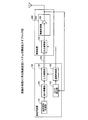
図1は、実施の形態1に係る無線送信システムの構成を示すブロック図である。この無線送信システムは、基地局装置100と無線装置200が光伝送路300によって接続された構成を採る。なお、図1においては、1つの無線装置200が基地局装置100に接続されているが、複数の無線装置200が基地局装置100に接続されても良い。
(Embodiment 1)
FIG. 1 is a block diagram showing a configuration of a wireless transmission system according to
基地局装置100は、送信信号を生成し、生成された送信信号を歪み補償した上で、光伝送路300を介して無線装置200へ送信する。このとき、基地局装置100は、歪み補償後の送信信号を減衰し、減衰後の送信信号を光伝送路300へ入力する。具体的には、基地局装置100は、送信信号生成部110、歪み補償部120、入力減衰部130、ACLR(Adjacent Channel Leakage power Ratio:隣接チャネル漏洩電力比)算出部140及び減衰制御部150を有する。
The
送信信号生成部110は、データの符号化及び変調などを実行し、送信信号を生成する。送信信号生成部110が生成する送信信号は、電気信号である。
The transmission
歪み補償部120は、送信信号生成部110によって生成された送信信号を歪み補償する。具体的には、歪み補償部120は、無線装置200に設けられる増幅器において発生する相互変調歪みの逆特性の歪みを送信信号に付与する。このとき、歪み補償部120は、例えば多項式を用いて送信信号に歪みを付与しても良く、送信信号の電力に応じた歪みをルックアップテーブルから読み出して送信信号に付与しても良い。
The
入力減衰部130は、光伝送路300の入力部分に設けられ、歪み補償後の送信信号の電力を減衰して光伝送路300へ入力する。このとき、入力減衰部130は、減衰制御部150によって指示される入力時減衰量だけ送信信号の電力を減衰する。後述するように、減衰量の調整期間においては、入力時減衰量は順次変更されるが、通常稼働期間においては、光伝送路300において発生する各種雑音を抑圧する入力時減衰量が入力減衰部130に設定される。
The
ACLR算出部140は、無線装置200において増幅された後の送信信号をフィードバックさせ、フィードバック信号に基づいてACLRを算出する。すなわち、ACLR算出部140は、無線装置200から無線送信される信号において、所定の送信帯域の帯域外へ漏洩している電力の比を算出する。ACLRは、隣接チャネルへの漏洩電力の比であるため、小さくするのが好ましい。
The
減衰制御部150は、所定の周期で減衰量の調整期間を設け、調整期間中に、光伝送路300へ入力される信号の最適な減衰量と光伝送路300から出力される信号の最適な減衰量とをACLRに基づいて決定する。すなわち、減衰制御部150は、調整期間中に、ACLRを最も小さくする入力時減衰量と出力時減衰量とを決定する。そして、減衰制御部150は、通常稼働期間においては、決定された最適な入力時減衰量及び出力時減衰量をそれぞれ入力減衰部130及び無線装置200の出力減衰部210に設定する。なお、減衰制御部150の詳細な構成及び動作については、後に詳述する。
The
なお、送信信号生成部110、歪み補償部120、ACLR算出部140及び減衰制御部150は、例えばCPU(Central Processing Unit)、FPGA(Field Programmable Gate Array)又はDSP(Digital Signal Processor)などのプロセッサと、RAM(Random Access Memory)又はROM(Read Only Memory)などのメモリとを用いて構成することができる。また、入力減衰部130は、減衰器を用いて構成することができる。
The transmission
無線装置200は、光伝送路300によって伝送された送信信号を減衰し、減衰後の送信信号を増幅して無線送信する。具体的には、無線装置200は、出力減衰部210及び無線処理部220を有する。
The
出力減衰部210は、光伝送路300からの出力部分に設けられ、光伝送路300から出力された送信信号の電力を減衰して無線処理部220へ出力する。このとき、出力減衰部210は、減衰制御部150によって指示される出力時減衰量だけ送信信号の電力を減衰する。後述するように、減衰量の調整期間においては、出力時減衰量は順次変更されるが、通常稼働期間においては、光伝送路300において発生する各種雑音を抑圧する出力時減衰量が出力減衰部210に設定される。なお、出力減衰部210は、減衰器を用いて構成することができる。
The
無線処理部220は、増幅器230を有し、出力減衰部210から出力される送信信号に対して所定の無線送信処理を実行する。具体的には、無線処理部220は、例えばD/A(Digital/Analogue)変換及びアップコンバートなどの無線送信処理を実行する。そして、無線処理部220は、無線送信処理後の信号を増幅器230によって増幅し、アンテナを介して無線送信する。
The
光伝送路300は、光ファイバを有し、入力減衰部130から入力される送信信号を光変調して光信号に変換し、得られた光信号を光ファイバによって無線装置200へ伝送する。そして、光伝送路300は、無線装置200へ伝送された光信号を光復調して電気信号に変換し、得られた電気信号を出力減衰部210へ出力する。光伝送路300によって伝送される過程で、送信信号には相互変調歪みや雑音が発生するが、本実施の形態では、入力減衰部130及び出力減衰部210による減衰によって相互変調歪や雑音が抑制され、良好なSFDR及びSNRを得ることができる。
The
次に、減衰制御部150の構成について、図2を参照しながら説明する。図2は、減衰制御部150の構成を示すブロック図である。図2に示す減衰制御部150は、ACLR比較部151、バッファ部152、アドレス設定部153、入力用ルックアップテーブル(以下「入力用LUT」と略記する)154及び出力用ルックアップテーブル(以下「出力用LUT」と略記する)155を有する。
Next, the configuration of the
ACLR比較部151は、最適な減衰量を決定するための調整期間において、入力時減衰量及び出力時減衰量を変更した場合のACLRを比較する。具体的には、ACLR比較部151は、ある入力時減衰量及び出力時減衰量が設定された状態でACLR算出部140によって算出されたACLRをバッファ部152に記憶させる。そして、ACLR比較部151は、入力時減衰量及び出力時減衰量が変更されると、これらの減衰量が変更された後にACLR算出部140によって算出されたACLRとバッファ部152に記憶されたACLRとを比較する。さらに、ACLR比較部151は、比較の結果小さい方のACLRをバッファ部152に記憶させる。
The
すなわち、ACLR比較部151は、入力時減衰量及び出力時減衰量が順次変更される際に、今回の変更前のACLRの最小値と今回の変更後のACLRとを比較し、必要に応じてバッファ部152に記憶させるACLRの最小値を変更する。そして、ACLR比較部151は、比較の結果をアドレス設定部153へ通知する。
That is, when the input attenuation amount and the output attenuation amount are sequentially changed, the
バッファ部152は、調整期間において入力時減衰量及び出力時減衰量が順次変更される場合に、ACLR比較部151による比較の結果に基づいて、今回の変更までにおけるACLRの最小値を記憶する。
When the input attenuation amount and the output attenuation amount are sequentially changed during the adjustment period, the
アドレス設定部153は、最適な減衰量を決定するための調整期間において、ACLR比較部151によるACLRの比較が完了するたびに、入力用LUT154及び出力用LUT155のアドレスを指定する。すなわち、アドレス設定部153は、ACLRの比較が完了するたびに、入力用LUT154及び出力用LUT155の未指定のアドレスを指定することにより、入力時減衰量及び出力時減衰量を変更する。また、アドレス設定部153は、入力用LUT154及び出力用LUT155のすべてのアドレスの指定が完了すると、ACLRの最小値に対応するアドレスを入力用LUT154及び出力用LUT155に設定する。すなわち、アドレス設定部153は、調整期間が終了して通常稼働期間になると、ACLRを最小にする入力時減衰量及び出力時減衰量が入力用LUT154及び出力用LUT155から出力されるように、それぞれのルックアップテーブルにアドレスを設定する。
The
入力用LUT154は、複数のアドレスそれぞれに対応付けて異なる入力時減衰量を保持する。また、出力用LUT155は、複数のアドレスそれぞれに対応付けて異なる出力時減衰量を保持する。ここで、入力用LUT154及び出力用LUT155の互いに対応するアドレスに対応付けて保持された減衰量の合計は一定値である。すなわち、アドレス設定部153から指定されるアドレスに保持された入力時減衰量と出力時減衰量との合計値は固定されている。したがって、例えば入力用LUT154及び出力用LUT155は、互いに等しい複数のアドレスを有しており、同じアドレスに保持された入力時減衰量と出力時減衰量との合計は一定値に等しくなっている。この一定値は、歪み補償部120から出力可能な送信信号の電力と増幅器230に入力可能な送信信号の電力とに基づいて定まる値である。
The
次いで、上記のように構成された減衰制御部150による減衰量決定処理について、図3に示すフロー図を参照しながら説明する。以下の減衰量決定処理は、所定の周期で到来する調整期間に実行され、通常稼働期間中は、減衰量決定処理によって決定された減衰量が入力減衰部130及び出力減衰部210に設定される。
Next, the attenuation determination process by the
調整期間が到来すると、アドレス設定部153によって、入力用LUT154及び出力用LUT155の初期アドレスが指定される。そして、入力用LUT154によって、初期アドレスに対応する入力時減衰量が入力減衰部130に設定され、出力用LUT155によって、初期アドレスに対応する出力時減衰量が出力減衰部210に設定される(ステップS101)。なお、初期アドレスに対応する入力時減衰量及び出力時減衰量の合計は、上述した一定値に等しい。
When the adjustment period arrives, the
初期アドレスに対応する入力時減衰量及び出力時減衰量がそれぞれ入力減衰部130及び出力減衰部210に設定されると、送信信号生成部110によって生成される送信信号は、歪み補償部120による歪み補償を経て、入力減衰部130によって減衰される。すなわち、初期アドレスに対応する入力時減衰量だけ送信信号の電力が減衰する。そして、減衰後の送信信号は光伝送路300へ入力され、光信号として無線装置200へ伝送され、電気信号に戻された後に出力減衰部210へ出力される。
When the input attenuation and output attenuation corresponding to the initial address are set in the
出力減衰部210には初期アドレスに対応する出力時減衰量が設定されているため、この出力減衰量だけ送信信号の電力が減衰する。そして、送信信号は、無線処理部220によって無線処理が施された後に増幅器230によって増幅される。増幅された送信信号は、アンテナから無線送信されるとともに、基地局装置100へフィードバックされ、フィードバック信号がACLR算出部140に入力される。そして、ACLR算出部140によって、初期アドレスに対応する入力時減衰量及び出力時減衰量が設定された状態におけるACLR0がフィードバック信号から算出される(ステップS102)。
Since the output attenuation amount corresponding to the initial address is set in the
算出されたACLR0は、減衰制御部150へ出力され、減衰制御部150のACLR比較部151によって、ACLRの最小値Lminとしてバッファ部152に格納される(ステップS103)。すなわち、初期状態のACLR0が暫定的にACLRの最小値Lminとしてバッファ部152に記憶される。
The calculated ACLR 0 is output to the
最小値Lminがバッファ部152に記憶されると、アドレス設定部153によって、指定アドレスが変更される。すなわち、アドレス設定部153によって、入力用LUT154及び出力用LUT155の初期アドレス以外の未指定のアドレスが指定される。そして、入力用LUT154によって、指定されたアドレスに対応する入力時減衰量が入力減衰部130に設定され、出力用LUT155によって、指定されたアドレスに対応する出力時減衰量が出力減衰部210に設定される(ステップS104)。なお、ここで指定されたアドレスに対応する入力時減衰量及び出力時減衰量の合計も、上述した一定値に等しい。
When the minimum value L min is stored in the
そして、初期アドレスに対応する入力時減衰量及び出力時減衰量が設定された場合と同様に、送信信号が光伝送路300の入力時及び出力時にそれぞれ減衰され、増幅器230によって増幅され、アンテナから無線送信される。また、増幅器230から出力される信号は、基地局装置100のACLR算出部140へフィードバックされ、ACLRが算出される(ステップS105)。
As in the case where the input attenuation and output attenuation corresponding to the initial address are set, the transmission signal is attenuated at the input and output of the
算出されたACLRは、減衰制御部150へ出力され、減衰制御部150のACLR比較部151によって、バッファ部152に保持されたACLRの最小値Lminと比較される(ステップS106)。すなわち、ここでは、バッファ部152に保持された初期状態のACLR0と今回算出されたACLRとの大小が比較される。
The calculated ACLR is output to the
この比較の結果、今回算出されたACLRの方が小さい場合には(ステップS106Yes)、このACLRが最小値Lminとしてバッファ部152に格納される(ステップS107)。すなわち、今回の減衰量の変更までの暫定的なACLRの最小値Lminがバッファ部152に記憶される。一方、バッファ部152に保持された最小値Lminが今回算出されたACLR以下である場合には(ステップS106No)、バッファ部152に保持された最小値Lminは更新されない。
As a result of this comparison, when the ACLR calculated this time is smaller (Yes in step S106), this ACLR is stored in the
ACLR比較部151による比較が完了すると、アドレス設定部153によって、入力用LUT154及び出力用LUT155のすべてのアドレスの指定が終了した否かが判定される(ステップS108)。この判定の結果、未指定のアドレスがある場合には(ステップS108No)、引き続き未指定のアドレスが指定されて入力時減衰量及び出力時減衰量が変更され、ACLRの最小値Lminの更新が繰り返される(ステップS104〜S107)。
When the comparison by the
また、入力用LUT154及び出力用LUT155のすべてのアドレスの指定が終了した場合には(ステップS108Yes)、バッファ部152に保持された最小値Lminが減衰量を変更した場合のACLRの最小値であることになる。そこで、アドレス設定部153によって、バッファ部152に保持された最小値Lminに対応するアドレスが入力用LUT154及び出力用LUT155へ通知され、通知されたアドレスに対応する減衰量がそれぞれ入力減衰部130及び出力減衰部210に設定される(ステップS109)。これにより、ACLRを最小にする入力時減衰量及び出力時減衰量が設定され、調整期間が終了して通常稼働期間に切り替わる。
In addition, when all the addresses of the
通常稼働期間においては、ACLRを最小にする入力時減衰量及び出力時減衰量がそれぞれ入力減衰部130及び出力減衰部210に設定されているため、送信信号の帯域外の電力が小さい。これは、光伝送路300による伝送によって送信信号の帯域外に付与される相互変調歪みや雑音が小さいことを意味しており、送信信号のSFDR及びSNRの劣化が最小限に抑制されることを意味している。より具体的には、入力減衰部130によって送信信号が減衰される結果、送信信号の電力は、光伝送路300における光変調時に線形性を維持可能な電力となり、特定の周波数帯域に発生する相互変調歪みが抑圧される。また、出力減衰部210によって送信信号が減衰される結果、送信信号の周波数によらず広い周波数帯域にわたって発生する熱雑音、ショット雑音及び相対強度雑音(RIN)が抑圧される。
During the normal operation period, the input attenuation and the output attenuation that minimize the ACLR are set in the
このように、送信信号の帯域外へ漏洩する電力を最小にする入力時減衰量及び出力時減衰量を決定し、光伝送路300の入力時及び出力時に送信信号を減衰することにより、送信信号の品質劣化を抑制することができる。特に、光伝送路300からの出力時にも送信信号を減衰するため、送信信号の周波数とは無関係に広帯域にわたって発生する雑音を抑圧することができる。このため、送信信号のSFDRのみではなく、SNRを改善することができる。
In this way, the attenuation amount at the time of input and the attenuation amount at the time of output that minimize the power leaking out of the band of the transmission signal is determined, and the transmission signal is attenuated at the time of input and output of the
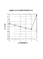
図4は、出力時減衰量とACLRの対応関係の具体例を示す図である。図4に示すように、出力時減衰量が変化するとACLRも変化しており、出力時減衰量が4dBのときにACLRが最小となっている。すなわち、光伝送路300から出力される送信信号を減衰しない場合には、ACLRが−53dBc程度であるのに対し、光伝送路300から出力される送信信号を4dB減衰する場合には、ACLRが−57dBc程度となっている。これは、出力減衰部210によって、光伝送路300において発生する熱雑音、ショット雑音及びRINが抑圧された結果、送信信号の帯域外の漏洩電力が減少したためと考えられる。そして、送信信号の帯域外の漏洩電力が減少することにより、送信信号のSNRが改善される。
FIG. 4 is a diagram illustrating a specific example of the correspondence relationship between the output attenuation amount and the ACLR. As shown in FIG. 4, when the output attenuation changes, the ACLR also changes. When the output attenuation is 4 dB, the ACLR is minimum. That is, when the transmission signal output from the
以上のように、本実施の形態によれば、光伝送路の入力部分及び出力部分に送信信号を減衰する減衰部を設け、ACLRを最小にする入力時減衰量と出力時減衰量とを調整期間中に決定する。そして、決定された入力時減衰量と出力時減衰量とをそれぞれの減衰部に設定し、送信信号を減衰する。このため、光伝送路における相互変調歪みの発生を抑制すると同時に、光伝送路において発生する熱雑音、ショット雑音及びRINを抑圧し、光ファイバによる信号の伝送を伴う場合でも信号の品質劣化を抑制することができる。 As described above, according to the present embodiment, the attenuation part for attenuating the transmission signal is provided in the input part and the output part of the optical transmission line, and the input attenuation and the output attenuation that minimize ACLR are adjusted. Decide during the period. Then, the determined input attenuation and output attenuation are set in the respective attenuation units, and the transmission signal is attenuated. For this reason, the generation of intermodulation distortion in the optical transmission line is suppressed, and at the same time, thermal noise, shot noise and RIN generated in the optical transmission line are suppressed, and signal quality deterioration is suppressed even when signal transmission through an optical fiber is involved. can do.
(実施の形態2)
実施の形態2の特徴は、送信信号の平均電力に応じた入力時減衰量及び出力時減衰量を決定し、送信信号を減衰する点である。
(Embodiment 2)
The feature of the second embodiment is that the attenuation amount at the time of input and the attenuation amount at the time of output corresponding to the average power of the transmission signal is determined and the transmission signal is attenuated.
図5は、実施の形態2に係る無線送信システムの構成を示すブロック図である。図5において、図1と同じ部分には同じ符号を付し、その説明を省略する。図5に示す無線送信システムは、図1に示す無線送信システムのACLR算出部140及び減衰制御部150に代えて、減衰制御部190を有する。
FIG. 5 is a block diagram showing a configuration of the wireless transmission system according to the second embodiment. 5, the same parts as those in FIG. 1 are denoted by the same reference numerals, and the description thereof is omitted. The wireless transmission system illustrated in FIG. 5 includes an
減衰制御部190は、送信信号の信号電力から平均電力を算出し、平均電力に応じた入力時減衰量及び出力時減衰量をそれぞれ入力減衰部130及び無線装置200の出力減衰部210に設定する。増幅器230の出力におけるACLRは、送信信号の信号電力によってほぼ決まっている。このため、ACLRを最小にする入力時減衰量及び出力時減衰量を、あらかじめ送信信号の信号電力ごとに記憶しておくことができる。そして、減衰制御部190は、送信信号の平均電力に対応して記憶された最適な入力時減衰量及び出力時減衰量を決定することができる。
The
図6は、減衰制御部190の構成を示すブロック図である。図6において、図2と同じ部分には同じ符号を付し、その説明を省略する。図6に示す減衰制御部190は、図2に示す減衰制御部150のACLR比較部151、バッファ部152及びアドレス設定部153に代えて、平均電力算出部191及びアドレス設定部192を有する。
FIG. 6 is a block diagram illustrating a configuration of the
平均電力算出部191は、送信信号生成部110によって生成された送信信号の信号電力を取得し、所定期間の信号電力の平均電力を算出する。
The average
アドレス設定部192は、平均電力算出部191によって算出された平均電力に対応する入力時減衰量及び出力時減衰量が入力用LUT154及び出力用LUT155から出力されるように、それぞれのルックアップテーブルにアドレスを設定する。
The
実施の形態2においては、送信信号の平均電力から最適な入力時減衰量及び出力時減衰量が決定されるため、減衰量の調整期間を設けて最適な入力時減衰量及び出力時減衰量を決定する必要がない。すなわち、減衰量を順次変更しながらフィードバック信号に基づいてACLRを算出したり比較したりする必要がない。このため、簡易な回路構成かつ容易な処理で減衰量を決定することができる。 In the second embodiment, since the optimal input attenuation and output attenuation are determined from the average power of the transmission signal, the optimal input attenuation and output attenuation are set by providing an attenuation adjustment period. There is no need to decide. That is, it is not necessary to calculate or compare the ACLR based on the feedback signal while sequentially changing the attenuation. Therefore, the attenuation can be determined with a simple circuit configuration and easy processing.
以上のように、本実施の形態によれば、光伝送路の入力部分及び出力部分に送信信号を減衰する減衰部を設け、送信信号の平均電力に応じてあらかじめ記憶された入力時減衰量と出力時減衰量とをそれぞれの減衰部に設定し、送信信号を減衰する。このため、簡易な回路構成かつ容易な処理で、光ファイバによる信号の伝送を伴う場合でも信号の品質劣化を抑制することができる。 As described above, according to the present embodiment, the attenuation part for attenuating the transmission signal is provided in the input part and the output part of the optical transmission line, and the input attenuation amount stored in advance according to the average power of the transmission signal The attenuation amount at the time of output is set in each attenuation section, and the transmission signal is attenuated. For this reason, signal quality deterioration can be suppressed with simple circuit configuration and easy processing even when signal transmission is performed by an optical fiber.
(実施の形態3)
実施の形態3の特徴は、歪み補償のために光伝送路を介してフィードバックされるフィードバック信号を光伝送路の入力部分及び出力部分で減衰する点である。
(Embodiment 3)
A feature of the third embodiment is that a feedback signal fed back through an optical transmission line for distortion compensation is attenuated at an input part and an output part of the optical transmission line.
図7は、実施の形態3に係る無線送信システムの構成を示すブロック図である。図7において、図1と同じ部分には同じ符号を付し、その説明を省略する。図7に示す無線送信システムにおいて、基地局装置100と無線装置200は、光伝送路600によって接続される。そして、基地局装置100は、送信信号生成部110、歪み補償部120及び出力減衰部410を有する。また、無線装置200は、無線処理部220、ACLR算出部510、減衰制御部520及び入力減衰部530を有する。
FIG. 7 is a block diagram showing a configuration of the wireless transmission system according to the third embodiment. 7, the same parts as those in FIG. 1 are denoted by the same reference numerals, and the description thereof is omitted. In the wireless transmission system shown in FIG. 7,
出力減衰部410は、光伝送路600からの出力部分に設けられ、光伝送路600から出力されたフィードバック信号の電力を減衰して歪み補償部120へ出力する。このとき、出力減衰部410は、減衰制御部520によって指示される出力時減衰量だけフィードバック信号の電力を減衰する。減衰量の調整期間においては、出力時減衰量は順次変更されるが、通常稼働期間においては、光伝送路600において発生する各種雑音を抑圧する出力時減衰量が出力減衰部410に設定される。
The
ACLR算出部510は、増幅器230によって増幅された後の送信信号をフィードバックさせ、フィードバック信号に基づいてACLRを算出する。すなわち、ACLR算出部510は、無線装置200から無線送信される信号において、所定の送信帯域の帯域外へ漏洩している電力の比を算出する。
The
減衰制御部520は、所定の周期で減衰量の調整期間を設け、調整期間中に、光伝送路600へ入力される信号の最適な減衰量と光伝送路600から出力される信号の最適な減衰量とをACLRに基づいて決定する。すなわち、減衰制御部520は、調整期間中に、ACLRを最も小さくする入力時減衰量と出力時減衰量とを決定する。そして、減衰制御部520は、通常稼働期間においては、決定された最適な入力時減衰量及び出力時減衰量をそれぞれ入力減衰部530及び基地局装置100の出力減衰部410に設定する。なお、減衰制御部520の内部構成は、実施の形態1に係る減衰制御部150(図2)と同様である。
The
入力減衰部530は、光伝送路600の入力部分に設けられ、フィードバック信号の電力を減衰して光伝送路600へ入力する。このとき、入力減衰部530は、減衰制御部520によって指示される入力時減衰量だけフィードバック信号の電力を減衰する。減衰量の調整期間においては、入力時減衰量は順次変更されるが、通常稼働期間においては、光伝送路600において発生する各種雑音を抑圧する入力時減衰量が入力減衰部530に設定される。
The
光伝送路600は、光ファイバを有し、入力減衰部530から入力されるフィードバック信号を光変調して光信号に変換し、得られた光信号を光ファイバによって基地局装置100へ伝送する。そして、光伝送路600は、基地局装置100へ伝送された光信号を光復調して電気信号に変換し、得られた電気信号を出力減衰部410へ出力する。光伝送路600によって伝送される過程で、フィードバック信号には相互変調歪みや雑音が発生するが、本実施の形態では、入力減衰部530及び出力減衰部410による減衰によって相互変調歪や雑音が抑制され、良好なSFDR及びSNRを得ることができる。
The
本実施の形態においては、実施の形態1と同様に、減衰量の調整期間において、ACLRを最小にする減衰量が決定される。すなわち、減衰制御部520によって入力時減衰量及び出力時減衰量が順次変更されながら、ACLR算出部510によって算出されるACLRを最小にする入力時減衰量及び出力時減衰量が決定される。具体的な減衰量決定処理は、実施の形態1と同様である。
In the present embodiment, similarly to the first embodiment, the attenuation amount that minimizes the ACLR is determined in the attenuation adjustment period. That is, while the
通常稼働期間においては、無線装置200から基地局装置100へのフィードバック信号が光伝送路600によって伝送される。このとき、調整期間において決定された入力時減衰量及び出力時減衰量がそれぞれ入力減衰部530及び出力減衰部410に設定され、光伝送路600の入力時及び出力時にフィードバック信号が減衰される。減衰後のフィードバック信号は、歪み補償部120へ入力される。
During the normal operation period, a feedback signal from the
歪み補償部120は、フィードバック信号を用いることにより、例えば歪み補償のための多項式の係数を更新したり、ルックアップテーブルを更新したりする。このとき、入力減衰部530及び出力減衰部410における減衰により、フィードバック信号の相互変調歪みや雑音が抑圧されているため、歪み補償部120へ入力されるフィードバック信号のSFDR及びSNRは良好である。この結果、歪み補償部120による係数やルックアップテーブルの更新の精度が向上し、歪み補償の精度も向上する。
The
図8は、入力時減衰量とACLRの対応関係の具体例を示す図である。図8に示すように、入力時減衰量が変化するとACLRも変化しており、入力時減衰量が23dBのときにACLRが最小となっている。このように、フィードバック信号が光伝送路600を介してフィードバックされる場合にも、ACLRを最小にする最適な減衰量が存在する。このため、本実施の形態では、調整期間中に、増幅器230の出力におけるACLRを最小にする最適な減衰量が決定され、通常稼働期間においては、光伝送路600の入力時及び出力時にフィードバック信号が減衰される。これにより、通常稼働期間において、送信信号のACLRが最小となり、SFDR及びSNRを改善することができる。
FIG. 8 is a diagram illustrating a specific example of the correspondence relationship between the input attenuation amount and the ACLR. As shown in FIG. 8, when the input attenuation amount changes, the ACLR also changes. When the input attenuation amount is 23 dB, the ACLR is minimum. As described above, even when the feedback signal is fed back through the
以上のように、本実施の形態によれば、光伝送路の入力部分及び出力部分にフィードバック信号を減衰する減衰部を設け、ACLRを最小にする入力時減衰量と出力時減衰量とを調整期間中に決定する。そして、決定された入力時減衰量と出力時減衰量とをそれぞれの減衰部に設定し、フィードバック信号を減衰する。このため、光伝送路における相互変調歪みの発生を抑制すると同時に、光伝送路において発生する熱雑音、ショット雑音及びRINを抑圧し、光ファイバによる信号の伝送を伴う場合でも信号の品質劣化を抑制することができる。また、フィードバック信号の品質劣化が抑制される結果、歪み補償の精度が向上し、送信信号の品質を向上することができる。 As described above, according to the present embodiment, the attenuation unit for attenuating the feedback signal is provided in the input part and the output part of the optical transmission line, and the input attenuation and the output attenuation that minimize ACLR are adjusted. Decide during the period. Then, the determined input attenuation and output attenuation are set in the respective attenuation units to attenuate the feedback signal. For this reason, the generation of intermodulation distortion in the optical transmission line is suppressed, and at the same time, thermal noise, shot noise and RIN generated in the optical transmission line are suppressed, and signal quality deterioration is suppressed even when signal transmission through an optical fiber is involved. can do. In addition, as a result of suppressing the quality deterioration of the feedback signal, the accuracy of distortion compensation is improved, and the quality of the transmission signal can be improved.
なお、上記各実施の形態においては、減衰量を決定する減衰制御部を基地局装置100及び無線装置200のどちらに設けても良い。すなわち、例えば実施の形態1、2において、減衰制御部150、190を無線装置200に設けても良く、実施の形態3において、減衰制御部520を基地局装置100に設けても良い。また、上記実施の形態3においては、ACLRを最小にする入力時減衰量と出力時減衰量とを調整期間中に決定してフィードバック信号を減衰するものとしたが、減衰量の決定は、実施の形態2と同様に行われても良い。すなわち、フィードバック信号の平均電力が算出され、フィードバック信号の平均電力に応じてあらかじめ記憶された入力時減衰量と出力時減衰量とがそれぞれの減衰部に設定され、フィードバック信号が減衰されるようにしても良い。
In each of the above embodiments, an attenuation control unit that determines an attenuation amount may be provided in either
また、上記各実施の形態は、適宜組み合わせて実施することが可能である。すなわち、例えば基地局装置100と無線装置200を光伝送路300及び光伝送路600によって接続し、送信信号及びフィードバック信号の双方が光ファイバを介して伝送されるようにしても良い。この場合、2つの光伝送路300及び光伝送路600の入力部分及び出力部分にそれぞれ減衰部が設けられ、送信信号及びフィードバック信号が減衰される。各減衰部の減衰量を決定する減衰制御部は、基地局装置100又は無線装置200に統合して設けられても良く、基地局装置100及び無線装置200に分離して設けられても良い。また、減衰制御部による減衰量の決定は、上記実施の形態1及び実施の形態3と同様に、調整期間中にACLRを最小にする減衰量を決定しても良く、送信信号の平均電力に応じた最適な減衰量をあらかじめ記憶するルックアップテーブルから決定しても良い。
The above embodiments can be implemented in combination as appropriate. That is, for example, the
さらに、上記各実施の形態において説明した減衰量決定処理をコンピュータが実行可能なプログラムとして記述することも可能である。この場合、このプログラムをコンピュータが読み取り可能な記録媒体に格納し、コンピュータに導入することも可能である。コンピュータが読み取り可能な記録媒体としては、例えばCD−ROM、DVDディスク、USBメモリなどの可搬型記録媒体や、例えばフラッシュメモリなどの半導体メモリが挙げられる。 Furthermore, the attenuation determination process described in each of the above embodiments can be described as a program executable by a computer. In this case, this program can be stored in a computer-readable recording medium and introduced into the computer. Examples of the computer-readable recording medium include a portable recording medium such as a CD-ROM, a DVD disk, and a USB memory, and a semiconductor memory such as a flash memory.
110 送信信号生成部
120 歪み補償部
130、530 入力減衰部
140、510 ACLR算出部
150、190、520 減衰制御部
151 ACLR比較部
152 バッファ部
153、192 アドレス設定部
154 入力用LUT
155 出力用LUT
191 平均電力算出部
210、410 出力減衰部
220 無線処理部
230 増幅器
300、600 光伝送路
DESCRIPTION OF
155 Output LUT
191 Average
Claims (9)
前記第1装置は、
送信信号を生成する生成部と、
前記生成部によって生成された送信信号を減衰し、前記光伝送路へ入力する第1減衰部とを有し、
前記第2装置は、
前記光伝送路から出力される送信信号を減衰する第2減衰部と、
前記第2減衰部によって減衰された送信信号を増幅する増幅部と、
前記増幅部による増幅後の送信信号を無線送信する送信部とを有し、
前記第1装置又は前記第2装置は、
前記第1減衰部及び前記第2減衰部における減衰量を制御する制御部をさらに有する
ことを特徴とする無線送信システム。 A wireless transmission system having a first device and a second device connected by an optical transmission line,
The first device includes:
A generator for generating a transmission signal;
A first attenuation unit that attenuates the transmission signal generated by the generation unit and inputs the transmission signal to the optical transmission line;
The second device includes:
A second attenuation unit for attenuating a transmission signal output from the optical transmission line;
An amplification unit for amplifying the transmission signal attenuated by the second attenuation unit;
A transmission unit that wirelessly transmits a transmission signal amplified by the amplification unit,
The first device or the second device is
The wireless transmission system further comprising: a control unit that controls an attenuation amount in the first attenuation unit and the second attenuation unit.
前記増幅部による増幅後の送信信号から所定の送信周波数帯域外の漏洩電力を算出する算出部を有し、
前記算出部によって算出される漏洩電力を最小にする前記第1減衰部及び前記第2減衰部それぞれの減衰量を決定し、決定した減衰量を前記第1減衰部及び前記第2減衰部に設定することを特徴とする請求項1記載の無線送信システム。 The controller is
A calculation unit that calculates leakage power outside a predetermined transmission frequency band from a transmission signal amplified by the amplification unit;
Attenuation amounts of the first attenuation unit and the second attenuation unit that minimize leakage power calculated by the calculation unit are determined, and the determined attenuation amounts are set in the first attenuation unit and the second attenuation unit. The wireless transmission system according to claim 1, wherein:
合計が所定値に等しい前記第1減衰部及び前記第2減衰部それぞれの減衰量の組み合わせのうち、前記算出部によって算出される漏洩電力を最小にする減衰量の組み合わせを決定することを特徴とする請求項2記載の無線送信システム。 The controller is
A combination of attenuation amounts that minimizes leakage power calculated by the calculation unit is determined from among the combinations of attenuation amounts of the first attenuation unit and the second attenuation unit whose total is equal to a predetermined value. The wireless transmission system according to claim 2.
前記生成部によって生成された送信信号の平均電力を算出する算出部を有し、
前記算出部によって算出される平均電力に対応付けて記憶部にあらかじめ記憶される前記第1減衰部及び前記第2減衰部それぞれの減衰量を取得し、取得した減衰量を前記第1減衰部及び前記第2減衰部に設定することを特徴とする請求項1記載の無線送信システム。 The controller is
A calculation unit that calculates an average power of the transmission signal generated by the generation unit;
The attenuation amounts of the first attenuation unit and the second attenuation unit, which are stored in advance in the storage unit in association with the average power calculated by the calculation unit, are acquired, and the acquired attenuation amounts are acquired in the first attenuation unit and The wireless transmission system according to claim 1, wherein the wireless transmission system is set in the second attenuation unit.
前記増幅部からフィードバックされるフィードバック信号を減衰し、前記光伝送路へ入力する第3減衰部をさらに有し、
前記第1装置は、
前記光伝送路から出力されるフィードバック信号を減衰する第4減衰部をさらに有し、
前記制御部は、
前記第3減衰部及び前記第4減衰部における減衰量をさらに制御する
ことを特徴とする請求項1記載の無線送信システム。 The second device includes:
A third attenuating unit for attenuating a feedback signal fed back from the amplifying unit and inputting it to the optical transmission line;
The first device includes:
A fourth attenuation unit for attenuating the feedback signal output from the optical transmission line;
The controller is
The wireless transmission system according to claim 1, further comprising controlling the amount of attenuation in the third attenuation unit and the fourth attenuation unit.
前記増幅部による増幅後の送信信号から所定の送信周波数帯域外の漏洩電力を算出する算出部を有し、
前記算出部によって算出される漏洩電力を最小にする前記第3減衰部及び前記第4減衰部それぞれの減衰量を決定し、決定した減衰量を前記第3減衰部及び前記第4減衰部に設定することを特徴とする請求項5記載の無線送信システム。 The controller is
A calculation unit that calculates leakage power outside a predetermined transmission frequency band from a transmission signal amplified by the amplification unit;
Attenuation amounts of the third attenuation unit and the fourth attenuation unit that minimize the leakage power calculated by the calculation unit are determined, and the determined attenuation amounts are set in the third attenuation unit and the fourth attenuation unit. The wireless transmission system according to claim 5, wherein:
合計が所定値に等しい前記第3減衰部及び前記第4減衰部それぞれの減衰量の組み合わせのうち、前記算出部によって算出される漏洩電力を最小にする減衰量の組み合わせを決定することを特徴とする請求項6記載の無線送信システム。 The controller is
A combination of attenuation amounts that minimizes leakage power calculated by the calculation unit is determined from among the combinations of attenuation amounts of the third attenuation unit and the fourth attenuation unit, the total of which is equal to a predetermined value. The wireless transmission system according to claim 6.
前記増幅部からフィードバックされるフィードバック信号の平均電力を算出する算出部を有し、
前記算出部によって算出される平均電力に対応付けて記憶部にあらかじめ記憶される前記第3減衰部及び前記第4減衰部それぞれの減衰量を取得し、取得した減衰量を前記第3減衰部及び前記第4減衰部に設定することを特徴とする請求項5記載の無線送信システム。 The controller is
A calculation unit that calculates an average power of a feedback signal fed back from the amplification unit;
The respective attenuation amounts of the third attenuation unit and the fourth attenuation unit, which are stored in advance in the storage unit in association with the average power calculated by the calculation unit, are acquired, and the acquired attenuation amounts are acquired by the third attenuation unit and The wireless transmission system according to claim 5, wherein the wireless transmission system is set in the fourth attenuation unit.
前記光伝送路の入力部及び出力部における減衰量を設定し、
前記装置間を伝送される信号を取得し、
取得された信号を前記入力部において減衰して前記光伝送路へ入力し、
前記光伝送路によって伝送され出力される信号を前記出力部において減衰する
処理を有することを特徴とする信号伝送方法。 A signal transmission method between devices connected by an optical transmission line,
Set attenuation at the input and output of the optical transmission line,
Obtaining a signal transmitted between the devices;
The acquired signal is attenuated at the input unit and input to the optical transmission line,
A signal transmission method comprising: a process of attenuating a signal transmitted and output by the optical transmission path at the output unit.
Priority Applications (2)
| Application Number | Priority Date | Filing Date | Title |
|---|---|---|---|
| JP2015135167A JP2017017639A (en) | 2015-07-06 | 2015-07-06 | Radio transmission system and signal transmission method |
| US15/157,609 US9692463B2 (en) | 2015-07-06 | 2016-05-18 | Wireless transmission system and signal transmission method |
Applications Claiming Priority (1)
| Application Number | Priority Date | Filing Date | Title |
|---|---|---|---|
| JP2015135167A JP2017017639A (en) | 2015-07-06 | 2015-07-06 | Radio transmission system and signal transmission method |
Publications (1)
| Publication Number | Publication Date |
|---|---|
| JP2017017639A true JP2017017639A (en) | 2017-01-19 |
Family
ID=57731455
Family Applications (1)
| Application Number | Title | Priority Date | Filing Date |
|---|---|---|---|
| JP2015135167A Pending JP2017017639A (en) | 2015-07-06 | 2015-07-06 | Radio transmission system and signal transmission method |
Country Status (2)
| Country | Link |
|---|---|
| US (1) | US9692463B2 (en) |
| JP (1) | JP2017017639A (en) |
Families Citing this family (2)
| Publication number | Priority date | Publication date | Assignee | Title |
|---|---|---|---|---|
| EP3716501B1 (en) * | 2019-03-28 | 2021-10-13 | Nokia Technologies Oy | Adapting guard band between adjacent channels |
| CN112013505B (en) * | 2019-05-31 | 2021-11-02 | 青岛海尔空调电子有限公司 | Method and device for controlling communication compensation and air conditioner |
Family Cites Families (4)
| Publication number | Priority date | Publication date | Assignee | Title |
|---|---|---|---|---|
| JP4397239B2 (en) * | 2004-01-15 | 2010-01-13 | 富士通株式会社 | Optical transmission system |
| CN102474304B (en) * | 2009-07-16 | 2014-11-12 | 索尼公司 | Communications system using adaptive frequency notching |
| JP2014103571A (en) | 2012-11-21 | 2014-06-05 | Ntt Docomo Inc | Transmission system |
| JP6248551B2 (en) * | 2013-11-05 | 2017-12-20 | 富士通株式会社 | Optical transmission system and optical transmission device |
-
2015
- 2015-07-06 JP JP2015135167A patent/JP2017017639A/en active Pending
-
2016
- 2016-05-18 US US15/157,609 patent/US9692463B2/en not_active Expired - Fee Related
Also Published As
| Publication number | Publication date |
|---|---|
| US9692463B2 (en) | 2017-06-27 |
| US20170012654A1 (en) | 2017-01-12 |
Similar Documents
| Publication | Publication Date | Title |
|---|---|---|
| KR101067099B1 (en) | Distortion compensation apparatus and method | |
| US8558616B2 (en) | Amplifying apparatus | |
| JP2009273110A (en) | Polar-modulation transmitting apparatus and method | |
| US9190959B2 (en) | Circuit, transceiver and mobile communication device | |
| US8385857B2 (en) | Wireless communication apparatus | |
| CA2921898C (en) | Amplifying stage working point determination | |
| JP5124655B2 (en) | Distortion compensation amplifier | |
| JP2010011062A (en) | Transmitting device and supply voltage setting method | |
| JP2015026968A (en) | Distortion compensation device and distortion compensation method | |
| US9363130B2 (en) | Dynamic digital predistortion for a microwave radio system | |
| JP2005151119A (en) | Distortion compensating apparatus | |
| JP2017017639A (en) | Radio transmission system and signal transmission method | |
| US20190222250A1 (en) | Handling of unwanted emissions from a radio communications device | |
| JP4841115B2 (en) | Extended predistortion method and apparatus | |
| JP6448022B2 (en) | Wireless communication apparatus, communication control method, and communication control program | |
| JP2013005354A (en) | Power amplifier and amplification control method | |
| JP2003078360A (en) | Distortion compensating equipment | |
| JP2012199716A (en) | Amplifier, transmission apparatus and gate voltage decision method | |
| JP2014011748A (en) | Distortion compensation device and distortion compensation method | |
| KR101134072B1 (en) | Method and High Power Amplifier for Transmitting Optimized Power through Digital Pre-Distortion or Analog Pre-Distortion of High Power Amplifier for Mobile Communication Repeater and Base Station | |
| JP2011250164A (en) | Amplifier circuit, and radio communication equipment using this | |
| JP5486613B2 (en) | Signal generating apparatus and signal generating method | |
| JP2017050694A (en) | Radio communication device and burst distortion correction method | |
| JP2011193156A (en) | Radio apparatus, distortion correction device, and distortion correction method | |
| JP2013115594A (en) | Power amplifier and amplification control method |