JP2017016071A - Image display device - Google Patents
Image display device Download PDFInfo
- Publication number
- JP2017016071A JP2017016071A JP2015135754A JP2015135754A JP2017016071A JP 2017016071 A JP2017016071 A JP 2017016071A JP 2015135754 A JP2015135754 A JP 2015135754A JP 2015135754 A JP2015135754 A JP 2015135754A JP 2017016071 A JP2017016071 A JP 2017016071A
- Authority
- JP
- Japan
- Prior art keywords
- communication data
- pwm signal
- image display
- backlight
- display device
- Prior art date
- Legal status (The legal status is an assumption and is not a legal conclusion. Google has not performed a legal analysis and makes no representation as to the accuracy of the status listed.)
- Pending
Links
Images

Abstract
Description
本発明は、バックライトを用いて輝度調整が行われる画像表示装置に関する。 The present invention relates to an image display apparatus in which brightness adjustment is performed using a backlight.
従来から、画像表示器に入力される信号の異常または画像表示器の作動の異常を検出したときに、画像表示器に含まれるバックライトの輝度を変化させることにより、文字等の複雑な画像の描画機能を有していない場合であっても画面表示を利用して異常の通知を行うことができる構成が知られている(例えば、特許文献1参照。)。また、この画像表示器の表示画面全体が異常の種類に応じた態様で点滅することにより、ユーザは、異常の発生および異常の内容を知ることができる。 Conventionally, when an abnormality in a signal input to the image display or an abnormality in the operation of the image display is detected, the brightness of a backlight included in the image display is changed, so that a complicated image such as a character is displayed. There is known a configuration capable of notifying abnormality using a screen display even when the drawing function is not provided (see, for example, Patent Document 1). Further, the entire display screen of the image display blinks in a manner corresponding to the type of abnormality, so that the user can know the occurrence of abnormality and the content of the abnormality.
ところで、上述した特許文献1に開示された画像表示器では、バックライトの輝度を変化させることにより、異常の有無やその内容をユーザに通知しているため、異常通知と並行して通常の画面表示を行う場合には、輝度が大きく変化することにより通常の画面表示の表示品質(視認性)が低下するという問題があった。また、特許文献1に開示された画像表示器は、異常発生を輝度変化によりユーザに伝えるためのものであるため、異常が発生していない画像表示器の内部動作等をデバッグしてその結果をユーザに伝えたり、表示内容とは別の情報をユーザに伝える用途に使うことができないという問題があった。 By the way, in the image display device disclosed in Patent Document 1 described above, the brightness of the backlight is changed to notify the user of the presence / absence of the abnormality and the contents thereof, so that the normal screen is displayed in parallel with the abnormality notification. When performing display, there is a problem that display quality (visibility) of normal screen display is deteriorated due to a large change in luminance. In addition, the image display disclosed in Patent Document 1 is for reporting the occurrence of an abnormality to the user by a change in luminance. Therefore, the internal operation or the like of the image display in which no abnormality has occurred is debugged and the result is displayed. There has been a problem that it cannot be used to convey information to the user or to convey information different from the displayed content to the user.
本発明は、このような点に鑑みて創作されたものであり、その目的は、内部状態等を外部に伝える際に、画面の輝度変化を抑えて画面表示の表示品質が低下することを防止することができる画像表示装置を提供することにある。また、本発明の他の目的は、異常発生の有無に関係なく画像表示器の内部動作等をデバッグしてその結果をユーザに伝えたり、表示内容とは別の情報をユーザに伝える用途に使うことができる画像表示装置を提供することにある。 The present invention was created in view of these points, and its purpose is to prevent the display quality of the screen display from deteriorating by suppressing the change in screen brightness when the internal state or the like is transmitted to the outside. An object of the present invention is to provide an image display device capable of performing the above. Another object of the present invention is to debug the internal operation of the image display regardless of whether or not an abnormality has occurred and to inform the user of the result, or to use it for transmitting information other than the display content to the user. An object of the present invention is to provide an image display device capable of performing the above.
上述した課題を解決するために、本発明の画像表示装置は、表示パネルと、表示パネルを背面から照明するバックライトと、外部に対する出力対象となる通信データを作成する通信データ作成手段と、バックライトの輝度をPWM制御によって調整するためのPWM信号であって、通信データ作成手段によって作成された通信データが重畳されたPWM信号を生成するPWM信号生成手段と、PWM信号生成手段によって生成されたPWM信号に基づいてバックライトを駆動するバックライト駆動手段とを備えている。また、上述したPWM信号生成手段は、PWM信号における点灯期間に対応して前記通信データを重畳することが望ましい。さらに、上述した表示パネルは、液晶表示パネルであることが望ましい。 In order to solve the above-described problems, an image display device of the present invention includes a display panel, a backlight that illuminates the display panel from the back, communication data generation means that generates communication data to be output to the outside, and a backlight. A PWM signal for adjusting the brightness of the light by PWM control, which is generated by the PWM signal generation unit, and a PWM signal generation unit that generates a PWM signal on which the communication data generated by the communication data generation unit is superimposed. Backlight driving means for driving the backlight based on the PWM signal. In addition, it is desirable that the PWM signal generation unit described above superimposes the communication data corresponding to the lighting period in the PWM signal. Furthermore, the display panel described above is preferably a liquid crystal display panel.
表示パネルと組み合わされるバックライトの輝度をPWM制御によって設定するために用いられるPWM信号に通信データを重畳しているため、内部状態等を外部に伝える際に、視覚的に確認できる程度に画面の輝度が大きく変化することがなく、画面表示の表示品質が低下することを防止することができる。 Since the communication data is superimposed on the PWM signal used to set the brightness of the backlight combined with the display panel by PWM control, when transmitting the internal state etc. to the outside, the screen can be visually confirmed. It is possible to prevent the display quality of the screen display from being deteriorated without greatly changing the luminance.
また、上述したPWM信号に重畳された通信データによるデューティ変化分を調整して通信データが重畳される前のPWM信号と同じデューティに補正するデューティ補正手段をさらに備えることが望ましい。これにより、バックライトの輝度を一定に維持することが可能となる。 In addition, it is preferable to further include a duty correction unit that adjusts the duty change due to the communication data superimposed on the PWM signal and corrects the duty change to the same as the PWM signal before the communication data is superimposed. Thereby, it becomes possible to maintain the brightness | luminance of a backlight constant.
また、上述したPWM信号生成手段は、PWM信号における点灯期間に対応して通信データを重畳し、デューティ補正手段は、PWM信号において点灯期間に対応して重畳された通信データによるデューティ減少分だけ消灯期間が短くなるように補正を行うことが望ましい。これにより、通信データを重畳することによるバックライトの輝度低下分を補正して一定の輝度を確保することが可能となる。 Further, the PWM signal generation means described above superimposes communication data corresponding to the lighting period in the PWM signal, and the duty correction means turns off by the duty reduction due to the communication data superimposed corresponding to the lighting period in the PWM signal. It is desirable to perform correction so as to shorten the period. As a result, it is possible to secure a certain luminance by correcting a decrease in luminance of the backlight caused by superimposing communication data.
また、上述した画像表示装置に含まれる各部の異常を検出する異常検出手段をさらに備え、通信データ作成手段は、異常検出手段によって検出された異常の有無、内容、異常発生箇所の少なくとも1つを含む通信データを作成することが望ましい。これにより、画像表示装置に含まれるいずれかの部位に異常が発生したときに、その時点における表示内容に影響を与えることなく、異常に関する情報を外部に伝えることが可能となる。 Further, the apparatus further includes abnormality detection means for detecting an abnormality of each part included in the image display device described above, and the communication data creation means determines at least one of the presence / absence, content, and abnormality occurrence location of the abnormality detected by the abnormality detection means. It is desirable to create communication data including. Accordingly, when an abnormality occurs in any part included in the image display device, it is possible to convey information regarding the abnormality to the outside without affecting the display content at that time.
また、上述した画像表示装置に含まれる各部の動作をデバッグするデバッグ手段をさらに備え、通信データ作成手段は、デバッグ手段によるデバッグによって得られた情報を含む通信データを作成することが望ましい。これにより、画像表示装置に含まれるいずれかの部位をデバッグした結果を、その時点における表示内容に影響を与えることなく、外部に伝えることが可能となる。 In addition, it is preferable that debugging means for debugging the operation of each unit included in the image display device described above is further provided, and the communication data creation means creates communication data including information obtained by debugging by the debugging means. As a result, the result of debugging any part included in the image display device can be transmitted to the outside without affecting the display contents at that time.
また、車両に搭載されており、表示パネルには、車両の走行に関する情報が表示され、通信データ作成手段は、この走行に関する情報を含む通信データを作成することが望ましい。これにより、表示パネルが故障して表示が困難になった場合であっても、車両の走行に関する情報(例えば、速度情報)を外部に伝えることができ、その内容を運転者等の利用者が確認することが可能となる。 Further, it is mounted on the vehicle, and the display panel displays information related to the traveling of the vehicle, and the communication data creating means desirably creates communication data including the information related to the traveling. As a result, even when the display panel is broken and display becomes difficult, it is possible to convey information related to vehicle travel (for example, speed information) to the outside, and the user such as the driver can communicate the contents. It becomes possible to confirm.
以下、本発明を適用した一実施形態の画像表示装置について、図面を参照しながら説明する。 Hereinafter, an image display apparatus according to an embodiment to which the present invention is applied will be described with reference to the drawings.
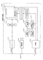
図1は、一実施形態の画像表示装置の構成を示す図である。図1に示す画像表示装置100は、例えば、車両に搭載されたヘッドユニットに組み込まれるものであって、ヘッドユニット本体(図示せず)から出力される映像信号に基づく画像表示を行うとともに、タッチパネルによって検出される利用者の指先等の位置をヘッドユニット本体に出力する。
FIG. 1 is a diagram illustrating a configuration of an image display apparatus according to an embodiment. An
画像表示装置100は、トランシーバ110、表示ドライバ112、表示パネル114、バックライト116、タッチパネル118、通信データ作成部120、PWM信号生成部122、デューティ補正部124、バックライトドライバ126、異常検出部130、デバッグ処理部132、電源回路140、制御部150を含んで構成されている。
The
トランシーバ110は、映像入力端子を介してヘッドユニット本体から入力されるLVDS(Low Voltage Differential Signaling)形式の映像信号をRGB形式の映像信号に変換する。表示ドライバ112は、このRGB形式の映像信号に基づいて表示パネル114を駆動し、この映像信号によって示される画像を表示する。表示パネル114は、例えばカラー液晶パネルであって、背面から照明するバックライト116と対向させた状態で組み付けられる。バックライト116は、例えばLEDによって形成されているが、それ以外の光源を用いるようにしてもよい。
The
また、タッチパネル118は、表示パネル114の表面に重ねて配置されており、利用者の指等が接触した画面上の位置を検出する。このタッチパネル118としては、例えば静電容量式のタッチパネルが用いられるが、その他の方式(抵抗膜方式等)のタッチパネルを用いるようにしてもよい。
The
通信データ作成部120は、画像表示装置100の外部への出力対象となる通信データを作成する。この通信データの具体例については後述する。PWM信号生成部122は、バックライト116の輝度をPWM(Pulse Width Modulation:パルス幅変調)制御によって調整するためのPWM信号であって、通信データ作成部120によって作成された通信データが重畳されたPWM信号を生成する。
The communication
デューティ補正部124は、PWM信号に重畳された通信データによるデューティ変化分を調整して、通信データが重畳される前のPWM信号と同じデューティに補正する。例えば、本実施形態では、PWM信号における点灯期間(オン期間)に対応して通信データが重畳される場合を想定しており、デューティ補正部124は、PWM信号において点灯期間に対応して重畳された通信データによるデューティ減少分だけ消灯期間が短くなるように補正を行う。上述したPWM信号生成部122では、このデューティ補正部124によって補正結果を加味したPWM信号が生成される。バックライトドライバ126は、PWM信号生成部122によって生成されたPWM信号に基づいてPWM制御を行ってバックライト116を駆動する。
The
異常検出部130は、画像表示装置100に含まれる各部の異常を検出する。上述した通信データ作成部120は、異常検出部130によって検出された異常の有無、異常の内容、異常発生箇所の少なくとも1つを含む通信データを作成する。
The
デバッグ処理部132は、画像表示装置100に含まれる各部の動作をデバッグする。例えば、このデバッグ処理部132は、デバッグ対象となる構成(例えば制御部150)から入出力される信号を監視しており、この監視結果を示す情報を作成する。上述した通信データ作成部120は、デバッグ処理部132によるデバッグによって得られた情報を含む通信データを作成する。
The
電源回路140は、バッテリ端子BATTを介してバッテリ(図示せず)に接続されており、画像表示装置100の各部に動作電力を供給する。
The
制御部150は、画像表示装置100全体を制御する。この制御部150は、通信端子Cを介してヘッドユニット本体に接続されており、例えばCAN(Controller Area Network)プロトコルにしたがった通信によってヘッドユニット本体との間で各種データの送受信を行う。例えば、利用者が表示画面の明るさの変更をヘッドユニット本体の操作部(図示せず)を用いて指示したときに、その指示が通信端子Cを介して制御部150に送られる。制御部150は、この指示に応じたバックライト116の輝度となるように、PWM信号のデューティを変更する。また、制御部150は、タッチパネル118を用いて利用者の指等の接触の有無を監視しており、指等が接触したときのその位置を検出し、この検出した位置を示す情報を通信端子Cを介してヘッドユニット本体に送信する。
The
上述した通信データ作成部120が通信データ作成手段に、PWM信号生成部122がPWM信号生成手段に、バックライトドライバ126がバックライト駆動手段に、デューティ補正部124がデューティ補正手段に、異常検出部130が異常検出手段に、デバッグ処理部132がデバッグ手段にそれぞれ対応する。
The communication
本実施形態の画像表示装置100はこのような構成を有しており、次に、通常の画像表示動作と並行して、通信データを外部に伝える動作について説明する。
The
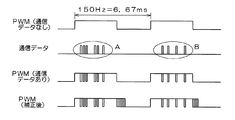
図2は、バックライト116をPWM制御する際のPWM信号波形を示す図である。図2において、「PWM(通信データなし)」は、通信データ作成部120によって作成された通信データが点灯期間(オン期間)に重畳される前のPWM信号の波形を示している。例えば、150HzのPWM信号を用いてバックライト116のPWM制御が行われるものとする。このPWM信号のデューティを変化させることにより、バックライト116の輝度調整が行われる。
FIG. 2 is a diagram showing a PWM signal waveform when the
「通信データ」は、通信データ作成部120によって作成される通信データの具体例を示している。例えば、9600〜4Mbps程度の通信速度を確保するものとすると、最小パルス幅が20μs〜50ns程度になり、PWM信号の点灯期間に通信データの複数ビットを割り当てることが可能となる。なお、図2に示す例では、A群に含まれる通信データとB群に含まれる通信データとが分かれて図示されているが、通信データ作成部120ではこれらA群とB群の一連の通信データが作成され、PWM信号生成部122によってPWM信号の点灯期間に重畳する際に、この点灯期間の長さに応じて割り当て可能なデータ量が決定されて、A群とB群に分けられる。
“Communication data” indicates a specific example of communication data created by the communication
「PWM(通信データあり)」は、「PWM(通信データなし)」で示されたPWM信号に、「通信データ」で示されたA群およびB群のそれぞれの通信データが重畳された後のPWM信号の波形を示している。 “PWM (with communication data)” is obtained by superimposing the communication data of the A group and B group indicated by “communication data” on the PWM signal indicated by “PWM (no communication data)”. The waveform of the PWM signal is shown.
「PWM(補正後)」は、「PWM信号(通信データあり)」で示されたPWM信号に対して、PWM信号において点灯期間に対応して重畳された通信データによるデューティ減少分だけ消灯期間が短くなるように補正を行った後のPWM信号の波形を示している。 “PWM (after correction)” has an extinguishing period corresponding to the duty reduction due to communication data superimposed on the PWM signal corresponding to the lighting period in the PWM signal indicated by “PWM signal (with communication data)”. The waveform of the PWM signal after correcting so as to be shorter is shown.
本実施形態では、図2の「PWM(補正後)」で示されるPWM信号を用いてバックライト116をPWM制御することにより、バックライト116を用いた照明に通信データを重畳させることができる。
In the present embodiment, by performing PWM control of the
図3は、バックライト116を用いた照明に重畳された通信データを画像表示装置100の外部で読み取る通信データ読取装置の一例を示す図である。図3に示す通信データ読取装置200は、受光部210、通信データ抽出部212、データ内容判定部214、表示処理部216、表示装置218を備えている。
FIG. 3 is a diagram illustrating an example of a communication data reading device that reads communication data superimposed on illumination using the
受光部210は、画像表示装置100の表示パネル114を通して出力されるバックライト116の照明光を受光して検出する。この検出された光には、表示パネル114を通すことで付加されるRGB情報も含まれる。通信データ抽出部212は、受光部210によって検出された光に含まれる通信データを抽出する。図2を用いて示したように、抽出対象となる通信データは、PWM信号の周波数よりも高い周波数を有しているため、例えば検出光の高域成分を分離することにより、通信データのみを抽出することが可能となる。データ内容判定部214は、通信データ抽出部212によって抽出された通信データの内容を判定する。上述したように、通信データには異常の有無、異常の内容、異常発生箇所やデバッグによって得られた情報(各部から入出力される信号)などが含まれており、データ内容判定部214は、これらを分離するとともにそれぞれによって示される異常の有無等を判定する。表示処理部216は、データ内容判定部214によって判定された内容を表示装置218に表示する。
The
ところで、上述した通信データ読取装置200は、専用のハードウエアによって実現することもできるが、スマートホン等の携帯端末装置を用いて実現するようにしてもよい。例えば、携帯端末装置に備わったカメラを受光部210として用い、携帯端末装置に備わった表示装置に通信データの内容を表示するようにしてもよい。また、バックライト116の照射光が赤外線領域の成分を含む場合には、IrDA規格にしたがった受光部を有する端末装置を用いてIrDA信号としての通信データを抽出するようにしてもよい。
By the way, the communication
このように、本実施形態の画像表示装置100では、表示パネル114と組み合わされるバックライト116の輝度をPWM制御によって設定するために用いられるPWM信号に通信データを重畳しているため、内部状態等を画像表示装置100の外部に伝える際に、画面の輝度が視認性に影響を与えるほど大きく変化することがなく、表示画面が輝度変化に伴ってちらつくこともなく、画面表示の表示品質が低下することを防止することができる。
As described above, in the
また、PWM信号における点灯期間に対応して通信データを重畳するとともに、PWM信号において点灯期間に対応して重畳された通信データによるデューティ減少分だけ消灯期間が短くなるように補正を行うことにより、通信データを重畳することによるバックライト126の輝度低下分を補正して一定の輝度を確保することが可能となる。
Further, by superimposing communication data corresponding to the lighting period in the PWM signal, and correcting so that the extinguishing period is shortened by the duty reduction due to the communication data superimposed corresponding to the lighting period in the PWM signal, It is possible to secure a certain luminance by correcting the luminance reduction of the
また、画像表示装置100に含まれる各部の異常を検出し、この検出された異常の有無、内容、異常発生箇所の少なくとも1つを含む通信データを作成することにより、画像表示装置100に含まれるいずれかの部位に異常が発生したときに、その時点における表示内容に影響を与えることなく、異常に関する情報を外部に伝えることが可能となる。
In addition, by detecting an abnormality of each unit included in the
また、デバッグによって得られた情報を含む通信データを作成することにより、画像表示装置100に含まれるいずれかの部位をデバッグした結果を、その時点における表示内容に影響を与えることなく、外部に伝えることが可能となる。
Further, by creating communication data including information obtained by debugging, the result of debugging any part included in the
なお、本発明は上記実施形態に限定されるものではなく、本発明の要旨の範囲内において種々の変形実施が可能である。例えば、上述した実施形態では、異常検出部130とデバッグ処理部132の両方を備え、異常発生とデバッグの両方に関する情報を含む通信データを作成したが、異常検出部130とデバッグ処理部132の一方を備え、異常発生とデバッグの一方に対応する情報を含む通信データを作成するようにしてもよい。
In addition, this invention is not limited to the said embodiment, A various deformation | transformation implementation is possible within the range of the summary of this invention. For example, in the above-described embodiment, both the
あるいは、その他の情報が含まれる通信データを作成するようにしてもよい。例えば、車両の走行に関する情報が表示パネル114に表示される場合に、通信データ作成部120は、この走行に関する情報を含む通信データを作成するようにしてもよい。運転席前方に取り付けられた画像表示装置100によって、車両の走行に関する情報として車速、エンジン回転数、各種警告灯の点灯の有無が表示される場合に、これらの内容を示すデータが制御部150に入力される場合を考えると、このデータを含む通信データを作成することにより、表示パネル114が故障して車速等の表示ができなくなった場合であっても、車速やエンジン回転数などを通信データ読取装置200の表示装置218に表示することができる。これにより、表示パネル114が故障して表示が困難になった場合であっても、速度等を運転者等が確認することが可能となる。なお、このようにして車両の走行に関する情報を通信データに含ませる場合に、上述した異常発生とデバッグの少なくとも一方の情報も併せて通信データに含ませるようにしてもよい(あるいは、含ませなくてもよい)。
Alternatively, communication data including other information may be created. For example, when information related to traveling of the vehicle is displayed on the
また、上述した実施形態では、デューティ補正部124を用いて、PWM信号に重畳された通信データによるデューティ変化分を調整して、通信データが重畳される前のPWM信号と同じデューティに補正するようにしたが、このデューティ補正部124による補正を行わないPWM信号(図2に示す「PWM(通信データあり)」)を用いるようにしてもよい。この場合には、通信データの内容に応じて輝度が減少するが、同じ効果(画面表示の表示品質低下防止)を得ることができる。
In the above-described embodiment, the
また、上述した実施形態では、PWM信号における点灯期間(オン期間)に対応して通信データが重畳される場合を考えたが、PWM信号の点灯期間および消灯期間の全体に対応して通信データを重畳するようにしてもよい。この場合にも、デューティ補正部124によってPWM信号のデューティを補正することにより、バックライト116の輝度を一定に維持することが可能となる。
In the above-described embodiment, the case where communication data is superimposed corresponding to the lighting period (ON period) in the PWM signal has been considered. However, the communication data is corresponding to the entire lighting period and extinguishing period of the PWM signal. You may make it superimpose. Also in this case, the luminance of the
上述したように、本発明によれば、表示パネルと組み合わされるバックライトの輝度をPWM制御によって設定するために用いられるPWM信号に通信データを重畳しているため、内部状態等を外部に伝える際に、視覚的に確認できる程度に画面の輝度が大きく変化することがなく、画面表示の表示品質が低下することを防止することができる。 As described above, according to the present invention, the communication data is superimposed on the PWM signal used for setting the luminance of the backlight combined with the display panel by the PWM control. In addition, the brightness of the screen does not change so much as can be visually confirmed, and the display quality of the screen display can be prevented from deteriorating.
100 画像表示装置
110 トランシーバ
112 表示ドライバ
114 表示パネル
116 バックライト
118 タッチパネル
120 通信データ作成部
122 PWM信号生成部
124 デューティ補正部
126 バックライトドライバ
130 異常検出部
132 デバッグ処理部
140 電源回路
150 制御部
DESCRIPTION OF
Claims (8)
前記表示パネルを背面から照明するバックライトと、
外部に対する出力対象となる通信データを作成する通信データ作成手段と、
前記バックライトの輝度をPWM制御によって調整するためのPWM信号であって、前記通信データ作成手段によって作成された通信データが重畳されたPWM信号を生成するPWM信号生成手段と、
前記PWM信号生成手段によって生成されたPWM信号に基づいて前記バックライトを駆動するバックライト駆動手段と、
を備えることを特徴とする画像表示装置。 A display panel;
A backlight for illuminating the display panel from the back;
Communication data creation means for creating communication data to be output to the outside;
PWM signal generating means for generating a PWM signal for adjusting the brightness of the backlight by PWM control, wherein the communication data generated by the communication data generating means is superimposed;
Backlight driving means for driving the backlight based on the PWM signal generated by the PWM signal generating means;
An image display device comprising:
前記PWM信号に重畳された前記通信データによるデューティ変化分を調整して前記通信データが重畳される前の前記PWM信号と同じデューティに補正するデューティ補正手段をさらに備えることを特徴とする画像表示装置。 In claim 1,
An image display apparatus, further comprising: a duty correction unit that adjusts a duty change due to the communication data superimposed on the PWM signal and corrects the duty change to be the same as that of the PWM signal before the communication data is superimposed. .
前記PWM信号生成手段は、前記PWM信号における点灯期間に対応して前記通信データを重畳することを特徴とする画像表示装置。 In claim 1 or 2,
The PWM signal generation unit superimposes the communication data corresponding to a lighting period in the PWM signal.
前記PWM信号生成手段は、前記PWM信号における点灯期間に対応して前記通信データを重畳し、
前記デューティ補正手段は、前記PWM信号において前記点灯期間に対応して重畳された前記通信データによるデューティ減少分だけ消灯期間が短くなるように補正を行うことを特徴とする画像表示装置。 In claim 2,
The PWM signal generating means superimposes the communication data corresponding to a lighting period in the PWM signal,
The image display apparatus according to claim 1, wherein the duty correction unit performs correction so that a light extinction period is shortened by a duty reduction by the communication data superimposed corresponding to the lighting period in the PWM signal.
前記画像表示装置に含まれる各部の異常を検出する異常検出手段をさらに備え、
前記通信データ作成手段は、前記異常検出手段によって検出された異常の有無、内容、異常発生箇所の少なくとも1つを含む前記通信データを作成することを特徴とする画像表示装置。 In any one of Claims 1-4,
Further comprising an abnormality detection means for detecting an abnormality of each part included in the image display device
The image display apparatus, wherein the communication data creation means creates the communication data including at least one of the presence / absence of an abnormality detected by the abnormality detection means, contents, and an abnormality occurrence location.
前記画像表示装置に含まれる各部の動作をデバッグするデバッグ手段をさらに備え、
前記通信データ作成手段は、前記デバッグ手段によるデバッグによって得られた情報を含む前記通信データを作成することを特徴とする画像表示装置。 In any one of Claims 1-5,
A debugging means for debugging the operation of each unit included in the image display device;
The image display device, wherein the communication data creating means creates the communication data including information obtained by debugging by the debugging means.
車両に搭載されており、
前記表示パネルには、車両の走行に関する情報が表示され、
前記通信データ作成手段は、この走行に関する情報を含む前記通信データを作成することを特徴とする画像表示装置。 In any one of Claims 1-6,
Mounted on the vehicle,
The display panel displays information related to vehicle travel,
The image display device, wherein the communication data creating means creates the communication data including information relating to the traveling.
前記表示パネルは、液晶表示パネルであることを特徴とする画像表示装置。 In any one of Claims 1-7,
The image display device, wherein the display panel is a liquid crystal display panel.
Priority Applications (1)
| Application Number | Priority Date | Filing Date | Title |
|---|---|---|---|
| JP2015135754A JP2017016071A (en) | 2015-07-07 | 2015-07-07 | Image display device |
Applications Claiming Priority (1)
| Application Number | Priority Date | Filing Date | Title |
|---|---|---|---|
| JP2015135754A JP2017016071A (en) | 2015-07-07 | 2015-07-07 | Image display device |
Publications (1)
| Publication Number | Publication Date |
|---|---|
| JP2017016071A true JP2017016071A (en) | 2017-01-19 |
Family
ID=57830607
Family Applications (1)
| Application Number | Title | Priority Date | Filing Date |
|---|---|---|---|
| JP2015135754A Pending JP2017016071A (en) | 2015-07-07 | 2015-07-07 | Image display device |
Country Status (1)
| Country | Link |
|---|---|
| JP (1) | JP2017016071A (en) |
Cited By (1)
| Publication number | Priority date | Publication date | Assignee | Title |
|---|---|---|---|---|
| WO2019097882A1 (en) * | 2017-11-14 | 2019-05-23 | パナソニックIpマネジメント株式会社 | Display device and display method |
Citations (9)
| Publication number | Priority date | Publication date | Assignee | Title |
|---|---|---|---|---|
| JP2007043706A (en) * | 2005-08-01 | 2007-02-15 | Avago Technologies Ecbu Ip (Singapore) Pte Ltd | Method and apparatus for communication using pulse-width-modulated visible light |
| WO2007060781A1 (en) * | 2005-11-25 | 2007-05-31 | Sharp Kabushiki Kaisha | Display device |
| JP2008269947A (en) * | 2007-04-20 | 2008-11-06 | Hitachi Displays Ltd | Liquid crystal display device |
| JP2011110942A (en) * | 2009-11-23 | 2011-06-09 | Nippon Seiki Co Ltd | On-vehicle display device |
| JP2011150135A (en) * | 2010-01-21 | 2011-08-04 | Denso Corp | Image display element |
| JP2012010269A (en) * | 2010-06-28 | 2012-01-12 | Outstanding Technology:Kk | Visual light communication transmitter |
| JP2013023081A (en) * | 2011-07-21 | 2013-02-04 | Nippon Seiki Co Ltd | Display system |
| JP2014151880A (en) * | 2013-02-13 | 2014-08-25 | Fuji Heavy Ind Ltd | Vehicular display system |
| WO2015059852A1 (en) * | 2013-10-25 | 2015-04-30 | パナソニック株式会社 | Display apparatus and control method therefor |
-
2015
- 2015-07-07 JP JP2015135754A patent/JP2017016071A/en active Pending
Patent Citations (9)
| Publication number | Priority date | Publication date | Assignee | Title |
|---|---|---|---|---|
| JP2007043706A (en) * | 2005-08-01 | 2007-02-15 | Avago Technologies Ecbu Ip (Singapore) Pte Ltd | Method and apparatus for communication using pulse-width-modulated visible light |
| WO2007060781A1 (en) * | 2005-11-25 | 2007-05-31 | Sharp Kabushiki Kaisha | Display device |
| JP2008269947A (en) * | 2007-04-20 | 2008-11-06 | Hitachi Displays Ltd | Liquid crystal display device |
| JP2011110942A (en) * | 2009-11-23 | 2011-06-09 | Nippon Seiki Co Ltd | On-vehicle display device |
| JP2011150135A (en) * | 2010-01-21 | 2011-08-04 | Denso Corp | Image display element |
| JP2012010269A (en) * | 2010-06-28 | 2012-01-12 | Outstanding Technology:Kk | Visual light communication transmitter |
| JP2013023081A (en) * | 2011-07-21 | 2013-02-04 | Nippon Seiki Co Ltd | Display system |
| JP2014151880A (en) * | 2013-02-13 | 2014-08-25 | Fuji Heavy Ind Ltd | Vehicular display system |
| WO2015059852A1 (en) * | 2013-10-25 | 2015-04-30 | パナソニック株式会社 | Display apparatus and control method therefor |
Cited By (3)
| Publication number | Priority date | Publication date | Assignee | Title |
|---|---|---|---|---|
| WO2019097882A1 (en) * | 2017-11-14 | 2019-05-23 | パナソニックIpマネジメント株式会社 | Display device and display method |
| JPWO2019097882A1 (en) * | 2017-11-14 | 2020-12-17 | パナソニックIpマネジメント株式会社 | Display device and display method |
| JP7209195B2 (en) | 2017-11-14 | 2023-01-20 | パナソニックIpマネジメント株式会社 | Display device and display method |
Similar Documents
| Publication | Publication Date | Title |
|---|---|---|
| EP3076384A1 (en) | Display device | |
| JP3610958B2 (en) | Luminance control device and monitor device | |
| JP6282601B2 (en) | Display device | |
| JP2007241286A (en) | Method and circuit for synchronous operation of display backlighting | |
| US20170174137A1 (en) | Mirror device with display function and display switching method | |
| JP2010032732A (en) | Liquid crystal display device | |
| US11442806B2 (en) | Vehicle display apparatus | |
| JP4180003B2 (en) | Projection-type image display device | |
| KR102178346B1 (en) | Display device, method for driving the same and image display system including the same | |
| JP2011216998A (en) | Image display device, image display system, image presenting method, and computer program | |
| JP2009276662A (en) | Liquid crystal display device and control method of liquid crystal display device | |
| US20090021467A1 (en) | Display Device | |
| JP2017174091A (en) | Awakening keeping device and awakening keeping method | |
| JP2017016071A (en) | Image display device | |
| JP2011150135A (en) | Image display element | |
| WO2020235683A1 (en) | Head-up display device | |
| KR101385264B1 (en) | Power saving control system and method for led electronic sign | |
| US9952492B2 (en) | Projection-type display device and light source control method therefor | |
| JP2021096391A (en) | Image display device | |
| JP6628659B2 (en) | Object approach detection device and object approach detection method | |
| JP2010271439A (en) | Display device for vehicle | |
| JP2016048298A (en) | Light emission control device, light emission control method and display device | |
| JP2008203768A (en) | Display device | |
| JP5266812B2 (en) | In-vehicle video presentation device and video presentation method | |
| JP2021162686A (en) | Video display device |
Legal Events
| Date | Code | Title | Description |
|---|---|---|---|
| A621 | Written request for application examination |
Free format text: JAPANESE INTERMEDIATE CODE: A621 Effective date: 20180308 |
|
| A977 | Report on retrieval |
Free format text: JAPANESE INTERMEDIATE CODE: A971007 Effective date: 20181031 |
|
| A131 | Notification of reasons for refusal |
Free format text: JAPANESE INTERMEDIATE CODE: A131 Effective date: 20181120 |
|
| A521 | Request for written amendment filed |
Free format text: JAPANESE INTERMEDIATE CODE: A523 Effective date: 20190109 |
|
| A02 | Decision of refusal |
Free format text: JAPANESE INTERMEDIATE CODE: A02 Effective date: 20190604 |